JP2011112312A - Heat cycle system of moving body - Google Patents
Heat cycle system of moving bodyDownload PDFInfo
- Publication number
- JP2011112312A JP2011112312AJP2009270979AJP2009270979AJP2011112312AJP 2011112312 AJP2011112312 AJP 2011112312AJP 2009270979 AJP2009270979 AJP 2009270979AJP 2009270979 AJP2009270979 AJP 2009270979AJP 2011112312 AJP2011112312 AJP 2011112312A
- Authority
- JP
- Japan
- Prior art keywords
- heat
- heat medium
- medium
- heat transfer
- cooling
- Prior art date
- Legal status (The legal status is an assumption and is not a legal conclusion. Google has not performed a legal analysis and makes no representation as to the accuracy of the status listed.)
- Pending
Links
Images


Classifications
- F—MECHANICAL ENGINEERING; LIGHTING; HEATING; WEAPONS; BLASTING
- F25—REFRIGERATION OR COOLING; COMBINED HEATING AND REFRIGERATION SYSTEMS; HEAT PUMP SYSTEMS; MANUFACTURE OR STORAGE OF ICE; LIQUEFACTION SOLIDIFICATION OF GASES
- F25B—REFRIGERATION MACHINES, PLANTS OR SYSTEMS; COMBINED HEATING AND REFRIGERATION SYSTEMS; HEAT PUMP SYSTEMS
- F25B5/00—Compression machines, plants or systems, with several evaporator circuits, e.g. for varying refrigerating capacity
- F25B5/02—Compression machines, plants or systems, with several evaporator circuits, e.g. for varying refrigerating capacity arranged in parallel
- B—PERFORMING OPERATIONS; TRANSPORTING
- B60—VEHICLES IN GENERAL
- B60H—ARRANGEMENTS OF HEATING, COOLING, VENTILATING OR OTHER AIR-TREATING DEVICES SPECIALLY ADAPTED FOR PASSENGER OR GOODS SPACES OF VEHICLES
- B60H1/00—Heating, cooling or ventilating [HVAC] devices
- B60H1/00357—Air-conditioning arrangements specially adapted for particular vehicles
- B60H1/00385—Air-conditioning arrangements specially adapted for particular vehicles for vehicles having an electrical drive, e.g. hybrid or fuel cell
- B60H1/00392—Air-conditioning arrangements specially adapted for particular vehicles for vehicles having an electrical drive, e.g. hybrid or fuel cell for electric vehicles having only electric drive means
- B—PERFORMING OPERATIONS; TRANSPORTING
- B60—VEHICLES IN GENERAL
- B60H—ARRANGEMENTS OF HEATING, COOLING, VENTILATING OR OTHER AIR-TREATING DEVICES SPECIALLY ADAPTED FOR PASSENGER OR GOODS SPACES OF VEHICLES
- B60H1/00—Heating, cooling or ventilating [HVAC] devices
- B60H1/00642—Control systems or circuits; Control members or indication devices for heating, cooling or ventilating devices
- B60H1/00814—Control systems or circuits characterised by their output, for controlling particular components of the heating, cooling or ventilating installation
- B60H1/00878—Control systems or circuits characterised by their output, for controlling particular components of the heating, cooling or ventilating installation the components being temperature regulating devices
- B60H1/00899—Controlling the flow of liquid in a heat pump system
- B60H1/00907—Controlling the flow of liquid in a heat pump system where the flow direction of the refrigerant changes and an evaporator becomes condenser
- B—PERFORMING OPERATIONS; TRANSPORTING
- B60—VEHICLES IN GENERAL
- B60H—ARRANGEMENTS OF HEATING, COOLING, VENTILATING OR OTHER AIR-TREATING DEVICES SPECIALLY ADAPTED FOR PASSENGER OR GOODS SPACES OF VEHICLES
- B60H1/00—Heating, cooling or ventilating [HVAC] devices
- B60H1/32—Cooling devices
- B60H1/3204—Cooling devices using compression
- B60H1/3228—Cooling devices using compression characterised by refrigerant circuit configurations
- B60H1/32284—Cooling devices using compression characterised by refrigerant circuit configurations comprising two or more secondary circuits, e.g. at evaporator and condenser side
- B—PERFORMING OPERATIONS; TRANSPORTING
- B60—VEHICLES IN GENERAL
- B60H—ARRANGEMENTS OF HEATING, COOLING, VENTILATING OR OTHER AIR-TREATING DEVICES SPECIALLY ADAPTED FOR PASSENGER OR GOODS SPACES OF VEHICLES
- B60H1/00—Heating, cooling or ventilating [HVAC] devices
- B60H1/00642—Control systems or circuits; Control members or indication devices for heating, cooling or ventilating devices
- B60H1/00814—Control systems or circuits characterised by their output, for controlling particular components of the heating, cooling or ventilating installation
- B60H1/00878—Control systems or circuits characterised by their output, for controlling particular components of the heating, cooling or ventilating installation the components being temperature regulating devices
- B60H2001/00928—Control systems or circuits characterised by their output, for controlling particular components of the heating, cooling or ventilating installation the components being temperature regulating devices comprising a secondary circuit
- B—PERFORMING OPERATIONS; TRANSPORTING
- B60—VEHICLES IN GENERAL
- B60H—ARRANGEMENTS OF HEATING, COOLING, VENTILATING OR OTHER AIR-TREATING DEVICES SPECIALLY ADAPTED FOR PASSENGER OR GOODS SPACES OF VEHICLES
- B60H1/00—Heating, cooling or ventilating [HVAC] devices
- B60H1/00642—Control systems or circuits; Control members or indication devices for heating, cooling or ventilating devices
- B60H1/00814—Control systems or circuits characterised by their output, for controlling particular components of the heating, cooling or ventilating installation
- B60H1/00878—Control systems or circuits characterised by their output, for controlling particular components of the heating, cooling or ventilating installation the components being temperature regulating devices
- B60H2001/00935—Control systems or circuits characterised by their output, for controlling particular components of the heating, cooling or ventilating installation the components being temperature regulating devices comprising four way valves for controlling the fluid direction
- F—MECHANICAL ENGINEERING; LIGHTING; HEATING; WEAPONS; BLASTING
- F25—REFRIGERATION OR COOLING; COMBINED HEATING AND REFRIGERATION SYSTEMS; HEAT PUMP SYSTEMS; MANUFACTURE OR STORAGE OF ICE; LIQUEFACTION SOLIDIFICATION OF GASES
- F25B—REFRIGERATION MACHINES, PLANTS OR SYSTEMS; COMBINED HEATING AND REFRIGERATION SYSTEMS; HEAT PUMP SYSTEMS
- F25B25/00—Machines, plants or systems, using a combination of modes of operation covered by two or more of the groups F25B1/00 - F25B23/00
- F25B25/005—Machines, plants or systems, using a combination of modes of operation covered by two or more of the groups F25B1/00 - F25B23/00 using primary and secondary systems
Landscapes
- Engineering & Computer Science (AREA)
- Physics & Mathematics (AREA)
- Mechanical Engineering (AREA)
- Thermal Sciences (AREA)
- General Engineering & Computer Science (AREA)
- Life Sciences & Earth Sciences (AREA)
- Sustainable Development (AREA)
- Sustainable Energy (AREA)
- Electric Propulsion And Braking For Vehicles (AREA)
Abstract
Translated fromJapaneseDescription
Translated fromJapanese本発明は、移動体に搭載された熱サイクルシステムに関する。 The present invention relates to a thermal cycle system mounted on a moving body.
移動体に搭載された熱サイクルシステムとしては、例えば特許文献1に開示されたものが知られている。特許文献1に開示された熱サイクルシステムは、電池及びDC/DCコンバータなどの発熱体を冷却する冷却システムと、室内の空気状態を調整する空調システムとを統合したものであり、空調用熱交換器及び発熱体に供給される熱媒体が循環する熱媒体循環サイクルと冷凍サイクルとを熱交換器によって熱的に接続し、冷凍サイクルの冷媒と熱媒体循環サイクルの熱媒体とを熱交換することにより、車室内の空調及び発熱体の冷却が行われるように構成されている。 As a thermal cycle system mounted on a moving body, for example, the one disclosed in
背景技術のように、冷却システムと空調システムとの統合を図った熱サイクルシステムを移動体に搭載するにあたっては、流路を構成する配管や構成部品が狭い設置スペース内において複雑に入り組むことが考えられる。熱サイクルシステムのメインテナンス性や小型化及び低コスト化の必要性などを考慮すると、熱サイクルシステムを移動体に搭載するにあたっては、構成部品の小型化や削減,共用化などによるシステム構成の簡素化が好ましい。 As in the background art, when a thermal cycle system that integrates a cooling system and an air conditioning system is mounted on a moving body, the piping and components that make up the flow path can be complicated in a small installation space. Conceivable. Considering the maintenance of the thermal cycle system and the need for downsizing and cost reduction, when mounting the thermal cycle system on a moving body, the system configuration is simplified by downsizing, reducing, and sharing components. Is preferred.
また、熱サイクルシステムを搭載した移動体において、発熱体の更なる小型及び高出力化が要求された場合、その要求に応えるためには、発熱体の冷却性能を更に向上させる必要がある。この場合、熱交換器の増設或いは大容量化によって発熱体の冷却性能を更に向上させることが考えられるが、熱サイクルシステムの小型化及び低コスト化の必要性などを考慮すると、熱交換器の増設或いは大容量化を伴うことなく対応できることが好ましい。 Further, in a moving body equipped with a heat cycle system, when further miniaturization and higher output of the heating element are required, it is necessary to further improve the cooling performance of the heating element in order to meet the demand. In this case, it is conceivable to further improve the cooling performance of the heating element by increasing the heat exchanger or increasing the capacity, but considering the necessity of downsizing and cost reduction of the heat cycle system, It is preferable that it is possible to cope without an expansion or an increase in capacity.
代表的な本発明の一つは、システム構成の簡素化を図ることができる熱サイクルシステムを提供する。 One of the representative aspects of the present invention provides a thermal cycle system capable of simplifying the system configuration.
ここに、代表的な本発明の一つは、冷媒が循環する冷凍サイクルシステムに第1中間熱交換器を介して熱的に接続された、発熱体の温度を調整するための熱媒体が循環する第1熱移動システムと、冷媒が循環する冷凍サイクルシステムに第2中間熱交換器を介して熱的に接続された、室内の空気状態を調整するための熱媒体が循環する第2熱移動システムとに対して、第1及び第2熱移動システムの循環路内の圧力を調整するためのリザーバタンクを共通に設けることを特徴とする。 Here, one of the representative aspects of the present invention circulates a heat medium for adjusting the temperature of the heating element, which is thermally connected to the refrigeration cycle system in which the refrigerant circulates via the first intermediate heat exchanger. First heat transfer system, and a second heat transfer in which a heat medium for adjusting the indoor air condition is thermally connected to the refrigeration cycle system in which the refrigerant circulates via a second intermediate heat exchanger A reservoir tank for adjusting the pressure in the circulation path of the first and second heat transfer systems is provided in common with the system.
また、代表的な本発明の一つは、第1熱移動システム及び第2熱移動システムの循環路を流通する熱媒体を外部に排出するためのドレイン排出機構を第1及び第2熱移動システムに対して共通に設けることを特徴とする。 One of the representative aspects of the present invention is that the first and second heat transfer systems have drain discharge mechanisms for discharging the heat medium flowing through the circulation paths of the first heat transfer system and the second heat transfer system to the outside. Is provided in common.
また、代表的な本発明の他の一つは、発熱体の温調性能を向上させることができる熱サイクルシステムを提供する。 Another representative aspect of the present invention provides a thermal cycle system capable of improving the temperature control performance of a heating element.
ここに、代表的な本発明の他の一つは、冷媒が循環する冷凍サイクルシステムに第1中間熱交換器を介して熱的に接続された、発熱体の温度を調整するための熱媒体が循環する第1熱移動システムの循環路と、冷媒が循環する冷凍サイクルシステムに第2中間熱交換器を介して熱的に接続された、室内の空気状態を調整するための熱媒体が循環する第2熱移動システムの循環路とを直列に接続できるように循環路接続制御部を設け、発熱体に供給される熱媒体の冷媒との熱交換量を、一つの中間熱交換器において冷媒と熱交換させるときよりも大きくしたいとき、発熱体に供給される熱媒体が第1中間熱交換器及び第2中間熱交換器を直列に流通するように、第1及び第2熱移動システムの循環路の接続を循環路接続制御部によって制御することを特徴とする。 Here, another representative aspect of the present invention is a heat medium for adjusting the temperature of the heating element, which is thermally connected to the refrigeration cycle system in which the refrigerant circulates via the first intermediate heat exchanger. A heat medium for adjusting the air condition in the room, which is thermally connected to the circulation path of the first heat transfer system through which the refrigerant circulates and the refrigeration cycle system through which the refrigerant circulates through the second intermediate heat exchanger, circulates. A circulation path connection control unit is provided so that the circulation path of the second heat transfer system can be connected in series, and the amount of heat exchange with the refrigerant of the heat medium supplied to the heating element is reduced in one intermediate heat exchanger. Of the first and second heat transfer systems so that the heat medium supplied to the heating element flows in series through the first intermediate heat exchanger and the second intermediate heat exchanger. The circuit connection is controlled by the circuit connection controller. And wherein the door.
また、代表的な本発明の他の一つは、冷媒が循環する冷凍サイクルシステムに第1中間熱交換器を介して熱的に接続され、少なくとも二つの発熱体の温度を調整するための熱媒体が循環する第1熱移動システムの循環路を発熱体の一つに、冷凍サイクルシステムに第2中間熱交換器を介して熱的に接続された、室内の空気状態を調整するための熱媒体が循環する第2熱移動システムの循環路を発熱体のもう一つに、それぞれ接続できるように循環路接続切替部を設け、少なくとも二つの発熱体と熱媒体との間の熱交換量を、少なくとも二つの発熱体と第1熱移動システムの熱媒体との間の熱交換量よりも大きくしたいとき、第1熱移動システムの熱媒体が発熱体の一つに、第2熱移動システムの熱媒体が発熱体のもう一つに、それぞれ供給されるように、第1及び第2熱移動システムの循環路の接続を循環路接続切替部によって切り替えることを特徴とする。 Further, another representative aspect of the present invention is a heat which is thermally connected to a refrigeration cycle system in which a refrigerant circulates via a first intermediate heat exchanger to adjust the temperatures of at least two heating elements. Heat for adjusting the air condition in the room, which is thermally connected to the refrigeration cycle system through the second intermediate heat exchanger with the circulation path of the first heat transfer system through which the medium circulates as one of the heating elements. A circulation path connection switching unit is provided so that the circulation path of the second heat transfer system in which the medium circulates can be connected to another heating element, and the amount of heat exchange between at least two heating elements and the heating medium can be reduced. When the heat exchange amount between at least two heat generating elements and the heat medium of the first heat transfer system is desired to be larger than the heat medium of the first heat transfer system, Each heating medium is supplied to another heating element. So that the, and switches the connection of the circulation path of the first and second heat transfer system by a circulation path connection switching unit.
代表的な本発明の一つによれば、第1及び第2熱移動システムにおいて構成部品の共用化を図ることができるので、熱サイクルシステムの簡素化を図ることができる。従って、代表的な本発明の一つによれば、移動体に搭載された熱サイクルシステムのメインテナンス性を向上させることができると共に、熱サイクルシステムの小型化及び低コスト化に貢献することができる。 According to one of the representative aspects of the present invention, the components can be shared in the first and second heat transfer systems, so that the heat cycle system can be simplified. Therefore, according to one of the representative aspects of the present invention, it is possible to improve the maintenance performance of the thermal cycle system mounted on the moving body, and to contribute to downsizing and cost reduction of the thermal cycle system. .
また、代表的な本発明の他の一つによれば、発熱体と熱媒体との熱交換量を大きくできるので、発熱体の温調性能を向上させることができる。従って、代表的な本発明の他の一つによれば、発熱体の更なる小型及び高出力化が要求された場合、その要求に応えることができる。しかも、熱サイクルシステムの大型化を伴うことなく、対応することができる。 Moreover, according to another one of the typical present invention, since the heat exchange amount between the heating element and the heat medium can be increased, the temperature control performance of the heating element can be improved. Therefore, according to another one of the representative aspects of the present invention, when further miniaturization and higher output of the heating element are required, the request can be met. And it can respond, without enlarging a thermal cycle system.
以下、本発明の実施例を説明する。 Examples of the present invention will be described below.
以下に説明する実施例では、本発明を、電動機を車両の唯一の駆動源とする純粋な電気自動車の熱サイクルシステムに適用した場合を例に挙げて説明する。 In the embodiments described below, the present invention will be described by taking as an example a case where the present invention is applied to a heat cycle system of a pure electric vehicle using an electric motor as the sole drive source of the vehicle.
以下に説明する実施例の構成は、内燃機関であるエンジンと電動機とを車両の駆動源とする電動車両、例えばハイブリッド自動車(乗用車),ハイブリッドトラックなどの貨物自動車,ハイブリッドバスなどの乗合自動車などの熱サイクルシステムに適用しても構わない。 The configuration of the embodiment described below is an electric vehicle having an internal combustion engine and an electric motor as a driving source of the vehicle, such as a hybrid vehicle (passenger vehicle), a freight vehicle such as a hybrid truck, and a shared vehicle such as a hybrid bus. You may apply to a heat cycle system.
まず、図3を用いて、本発明の熱サイクルシステムが適用される純粋な電気自動車(以下、単に「EV」と記述する)の電動機駆動システムについて説明する。 First, a motor drive system of a pure electric vehicle (hereinafter simply referred to as “EV”) to which the heat cycle system of the present invention is applied will be described with reference to FIG.
図3は、EV1000の駆動系の構成及びその一部を構成する電動機駆動システムの各コンポーネントの電気的な接続構成を示す。 FIG. 3 shows the configuration of the drive system of the
尚、図3において、太い実線は強電系を示し、細い実線は弱電系を示す。 In FIG. 3, a thick solid line indicates a strong electric system, and a thin solid line indicates a weak electric system.
図示省略した車体のフロント部或いはリア部には車軸820が回転可能に軸支されている。車軸820の両端には一対の駆動輪800が設けられている。図示省略したが、車体のリア部或いはフロント部には、両端に一対の従動輪が設けられた車軸が回転可能に軸支されている。図3に示すEV1000では、駆動輪800を前輪とし、従動輪を後輪とした前輪駆動方式を示しているが、駆動輪800を後輪とし、従動輪を前輪とした後輪駆動方式もある。 An
車軸820の中央部にはデファレンシャルギア(以下、「DEF」と記述する)830が設けられている。車軸820はDEF830の出力側に機械的に接続されている。DEF830の入力側には変速機810の出力軸が機械的に接続されている。DEF830は、変速機810によって変速されて伝達された回転駆動力を左右の車軸820に分配する差動式動力分配機構である。変速機810の入力側にはモータジェネレータ200の出力側が機械的に接続されている。 A differential gear (hereinafter referred to as “DEF”) 830 is provided at the center of the
モータジェネレータ200は、電機子巻線211を備えた電機子(図3に示すEV1000では固定子が相当)210と、電機子210に空隙を介して対向配置されると共に、永久磁石221を備えた界磁(図3に示すEV1000では回転子が相当)220とを有する回転電機であり、EV1000の力行時にはモータとして機能し、回生時にはジェネレータとして機能する。 The
モータジェネレータ200がモータとして機能する場合には、バッテリ100に蓄積された電気エネルギーがインバータ装置300を介して電機子巻線211に供給される。これにより、モータジェネレータ200は電機子210と界磁220との間の磁気的作用により回転動力(機械エネルギー)を発生する。モータジェネレータ200から出力された回転動力は、変速機810及びDEF830を介して車軸820に伝達され、駆動輪800を駆動する。 When
モータジェネレータ200がジェネレータとして機能する場合には、駆動輪800から伝達された機械エネルギー(回転動力)がモータジェネレータ200に伝達され、モータジェネレータ200を駆動する。このように、モータジェネレータ200が駆動されると、電機子巻線211には界磁220の磁束が鎖交して電圧が誘起される。これにより、モータジェネレータ200は電力を発生する。モータジェネレータ200から出力された電力はインバータ装置300を介してバッテリ100に供給される。これにより、バッテリ100は充電される。 When
モータジェネレータ200、特に電機子210は、後述する熱サイクルシステムによってその温度が許容温度範囲内になるように調節されている。電機子210は発熱部品であるので冷却が必要であると共に、周囲温度が低温の時には所定の電気特性が得られるように、暖気が必要になる場合もある。 The
モータジェネレータ200は、電機子210とバッテリ100との間の電力がインバータ装置300によって制御されることにより駆動する。すなわちインバータ装置300はモータジェネレータ200の制御装置である。インバータ装置300は、スイッチング半導体素子のスイッチング動作によって電力を直流から交流に、交流から直流に変換する電力変換装置であり、パワーモジュール310,パワーモジュール310に実装されたスイッチング半導体素子を駆動する駆動回路330,パワーモジュール310の直流側に電気的に並列に接続され、直流電圧を平滑する電解コンデンサ320、及びパワーモジュール310のスイッチング半導体素子のスイッチング指令を生成し、このスイッチング指令に対応する信号を駆動回路330に出力するモータ制御装置340を備えている。 The
パワーモジュール310は、二つの(上アーム及び下アームの)スイッチング半導体素子を電気的に直列に接続し直列回路(一相分のアーム)が三相分,電気的に並列に接続(三相ブリッジ接続)されて電力変換回路が構成されるように、六つのスイッチング半導体素子を基板上に実装し、アルミワイヤなどの接続導体によって電気的に接続した構造体である。 In the
スイッチング半導体素子としては金属酸化膜半導体型電界効果トランジスタ(MOSFET)或いは絶縁ゲート型バイポーラトランジスタ(IGBT)を用いている。ここで、電力変換回路をMOSFETによって構成する場合、ドレイン電極とソース電極との間には寄生ダイオードが存在するので、別途、それらの間にダイオード素子を実装する必要がない。一方、電力変換回路をIGBTによって構成する場合、コレクタ電極とエミッタ電極との間にはダイオード素子が存在していないので、別途、それらの間にダイオード素子を電気的に逆並列に接続する必要がある。 As the switching semiconductor element, a metal oxide semiconductor field effect transistor (MOSFET) or an insulated gate bipolar transistor (IGBT) is used. Here, when the power conversion circuit is configured by a MOSFET, a parasitic diode exists between the drain electrode and the source electrode, so that it is not necessary to separately mount a diode element between them. On the other hand, when the power conversion circuit is constituted by an IGBT, there is no diode element between the collector electrode and the emitter electrode. Therefore, it is necessary to separately connect the diode element electrically in antiparallel between them. is there.
各上アームの下アーム接続側とは反対側(IGBTの場合、コレクタ電極側)はパワーモジュール310の直流側から外部に導出され、バッテリ100の正極側に電気的に接続されている。各下アームの上アーム接続側とは反対側(IGBTの場合、エミッタ電極側)はパワーモジュール310の直流側から外部に導出され、バッテリ100の負極側に電気的に接続されている。各アームの中点、すなわち上アームの下アーム接続側(IGBTの場合、上アームのエミッタ電極側)と下アームの上アーム接続側(IGBTの場合、下アームのコレクタ電極側)との接続点はパワーモジュール310の交流側から外部に導出され、電機子巻線211の対応する相の巻線に電気的に接続されている。 The side opposite to the lower arm connection side of each upper arm (collector electrode side in the case of IGBT) is led out from the DC side of the
電解コンデンサ320は、スイッチング半導体素子の高速スイッチング動作及び電力変換回路に寄生するインダクタンスに起因して生じる電圧変動を抑制するために、すなわち直流成分に含まれる交流成分を除去する平滑コンデンサである。平滑コンデンサとしては電解コンデンサ320の代わりにフィルムコンデンサを用いることもできる。 The
モータ制御装置340は、車両全体の制御を司る車両制御装置840から出力されたトルク指令信号を受けて、六つのスイッチング半導体素子に対するスイッチング指令信号(例えばPWM(パルス幅変調)信号)を生成し、駆動回路330に出力する電子回路装置である。 The
駆動回路330は、モータ制御装置340から出力されたスイッチング指令信号を受けて、六つのスイッチング半導体素子に対する駆動信号を生成し、六つのスイッチング半導体素子のゲート電極に出力する電子回路装置である。 The
インバータ装置300、特にパワーモジュール310及び電解コンデンサ320は、後述する熱サイクルシステムによってその温度が許容温度範囲内になるように調節されている。パワーモジュール310及び電解コンデンサ320は発熱部品であるので冷却が必要であると共に、周囲温度が低温の時には所定の動作特性や電気特性が得られるように、暖気が必要になる場合もある。 The
車両制御装置840は、運転者からのトルク要求(アクセルペダルの踏み込み量或いはスロットルの開度),車両の速度など、車両の運転状態を示す複数の状態パラメータに基づいて、モータ制御装置340に対するモータトルク指令信号を生成し、そのモータトルク指令信号をモータ制御装置340に出力する。 The
バッテリ100は、モータジェネレータ200の駆動用電源を構成する、公称出力電圧200ボルト以上の高電圧であり、ジャンクションボックス400を介してインバータ装置300及び充電器500に電気的に接続されている。バッテリ100としてはリチウムイオンバッテリを用いている。 The
尚、バッテリ100としては、鉛電池,ニッケル水素電池,電気二重層キャパシタ,ハイブリッドキャパシタなど、他の蓄電器を用いることもできる。 As the
バッテリ100は、インバータ装置300及び充電器500によって充放電される蓄電装置であり、主要部として電池部110及び制御部を備えている。 The
電池部110は電気エネルギーの貯蔵庫であり、電気エネルギーの蓄積及び放出(直流電力の充放電)が可能な複数のリチウムイオン電池が電気的に直列に接続されたものから構成され、インバータ装置300及び充電器500に電気的に接続されている。 The
制御部は、複数の電子回路部品から構成された電子制御装置であり、電池部110の状態を管理及び制御すると共に、インバータ装置300及び充電器500に許容充放電量を提供して、電池部110における電気エネルギーの出入りを制御する。 The control unit is an electronic control device composed of a plurality of electronic circuit components. The control unit manages and controls the state of the
電子制御装置は、機能上、2つの階層に分かれて構成されており、バッテリ100内において上位(親)に相当するバッテリ制御装置130と、バッテリ制御装置130に対して下位(子)に相当するセル制御装置120とを備えている。 The electronic control device is functionally divided into two layers, and corresponds to the upper (parent)
セル制御装置120は、バッテリ制御装置130から出力された指令信号に基づいてバッテリ制御装置130の手足となって動作し、複数のリチウムイオン電池のそれぞれの状態を管理及び制御する複数の電池管理手段を備えている。複数の電池管理手段はそれぞれ集積回路(IC)によって構成されている。複数の集積回路は、電気的に直列に接続された複数のリチウムイオン電池をいくつかのグループに分けたとき、そのグループのそれぞれに対応して設けられ、対応するグループが有する複数のリチウムイオン電池のそれぞれの電圧及び過充放電異常を検出すると共に、対応するグループが有する複数のリチウムイオン電池間に充電状態のバラツキがある場合には、所定の充電状態よりも大きなリチウムイオン電池を放電して、対応するグループが有する複数のリチウムイオン電池間の充電状態が揃うように、対応するグループが有する複数のリチウムイオン電池のそれぞれの状態を管理及び制御する。 The
バッテリ制御装置130は、電池部110の状態を管理及び制御すると共に、車両制御装置840又はモータ制御装置340に許容充放電量を通知して、電池部110における電気エネルギーの出入りを制御する電子制御装置であり、状態検知手段を備えている。状態検知手段は、マイクロコンピュータやディジタルシグナルプロセッサなどの演算処理装置である。 The
バッテリ制御装置130の状態検知手段1には、電池部110の充放電電流を計測するための電流計測手段,電池部110の充放電電圧を計測するための電圧計測手段及び電池部110及びいくつかのリチウムイオン電池の温度を計測するための温度計測手段から出力された計測信号,セル制御装置120から出力された、複数のリチウムイオン電池の端子間電圧に関する検出信号,セル制御装置120から出力された異常信号,イグニションキースイッチの動作に基づくオンオフ信号、及び上位制御装置である車両制御装置840又はモータ制御装置340から出力された信号を含む複数の信号が入力されている。 The
バッテリ制御装置130の状態検知手段は、それらの入力信号から得られた情報、予め設定された、リチウムイオン電池の特性情報及び演算に必要な演算情報を含む複数の情報に基づいて、電池部110の充電状態(SOC:State of charge)及び劣化状態(SOH:State of health)などを検知するための演算,複数のリチウムイオン電池の充電状態をバランスさせるための演算、及び電池部110の充放電量を制御するための演算を含む複数の演算を実行する。そして、バッテリ制御装置130の状態検知手段は、それらの演算結果に基づいて、セル制御装置120に対する指令信号,電池部110の充放電量を制御するための許容充放電量に関する信号,電池部110のSOCに関する信号、及び電池部110のSOHに関する信号を含む複数の信号を生成して出力する。 The state detection means of the
また、バッテリ制御装置130の状態検知手段は、セル制御装置120から出力された異常信号に基づいて、第1正極及び負極リレー410,420を遮断するための指令信号、及び異常状態を通知するための信号を含む複数の信号を生成して出力する。 Further, the state detection means of the
バッテリ制御装置130及びセル制御装置120は、信号伝送路によってお互いに信号の授受ができるようになっているが、電気的には絶縁されている。これは、お互いの動作電源が異なり、お互いに基準電位が異なるためである。このため、バッテリ制御装置130及びセル制御装置120の間を結ぶ信号伝送路上にはフォトカプラ,容量性結合素子,変圧器などの絶縁140が設けられている。これにより、バッテリ制御装置130及びセル制御装置120は、お互いに基準電位の異なる信号を用いて信号伝送ができる。 The
バッテリ100は、特に電池部110は、後述する熱サイクルシステムによってその温度が許容温度範囲内になるように調節されている。電池部110は発熱部品であるので冷却が必要であると共に、周囲温度が低温の時には所定の入出力特性が得られるように、暖気が必要になる場合もある。 The
バッテリ100に蓄積された電気エネルギーは、EV1000を走行させる電動機駆動システムの駆動用電力として使用される。バッテリ100への電気エネルギーの蓄積は、電動機駆動システムの回生動作により生成された回生電力、或いは家庭向け商用電源から取り込んだ電力、若しくは電気スタンドから購入した電力により行われる。 The electric energy stored in the
家庭の商用電源600或いは電気スタンドの給電装置からバッテリ100を充電する場合、充電器500の外部電源接続端子に電気的に接続された電源ケーブルの先端の電源プラグ550を商用電源600側のコンセント700に差し込み或いは電気スタンドの給電装置から延びる電源ケーブルを充電器500の外部電源接続端子に接続し、充電器500と商用電源600或いは電気スタンドの給電装置とを電気的に接続する。これにより、交流電力が商用電源600或いは電気スタンドの給電装置から充電器500に供給される。充電器500は、供給された交流電力を直流電力に変換し、かつバッテリ100の充電電圧に調整した後、バッテリ100に供給する。これにより、バッテリ100は充電される。 When charging the
尚、電気スタンドの給電装置からの充電も基本的には家庭の商用電源600からの充電と同じように行われる。但し、家庭の商用電源600からの充電と電気スタンドの給電装置からの充電とでは、充電器500に供給される電流容量及び充電時間が異なり、電気スタンドの給電装置からの充電の方が、家庭の商用電源600からの充電よりも電流容量が大きく、かつ充電時間が速い、すなわち急速充電ができる。 Note that charging from the power supply device of the desk lamp is basically performed in the same manner as charging from the
電器500は、家庭の商用電源600から供給された交流電力或いは電気スタンドの給電装置から供給された交流電力を直流電力に変換すると共に、この変換された直流電力をバッテリ100の充電電圧に昇圧してバッテリ100に供給する電力変換装置であり、交直変換回路510,昇圧回路520,駆動回路530及び充電制御装置540を主な構成機器として備えている。
交直変換回路510は、外部電源から供給された交流電力を直流電力に変換して出力する電力変換回路であり、例えば複数のダイオード素子のブリッジ接続により構成され、外部電源から供給された交流電力を直流電力に整流するために設けられた整流回路、及び整流回路の直流側に電気的に接続され、整流回路の出力の力率を改善するために設けられた力率改善回路を備えている。交流電力を直流電力に変換する回路としては、ダイオード素子が逆並列に接続された複数のスイッチング半導体素子のブリッジ接続により構成された回路を用いても構わない。 The AC /
昇圧回路520は、交直変換回路510(力率改善回路)から出力された直流電力をバッテリ100の充電電圧まで昇圧するための電力変換回路であり、例えば絶縁型のDC−DCコンバータにより構成されている。絶縁型のDC−DCコンバータは、変圧器,変圧器の一次側巻線に電気的に接続されると共に、複数のスイッチング半導体素子のブリッジ接続により構成され、交直変換回路510から出力された直流電力を交流電力に変換して変圧器の一次側巻線に入力する変換回路,変圧器の二次側巻線に電気的に接続されると共に、複数のダイオード素子のブリッジ接続により構成され、変圧器の二次側巻線に発生した交流電力を直流電力に整流する整流回路,整流回路の出力側(直流側)の正極側に電気的に直列に接続された平滑リアクトル,整流回路の出力側(直流側)の正負極間に電気的に並列に接続された平滑コンデンサから構成されている。 The step-up
充電制御装置540は、充電器500によるバッテリ100の充電終始や、充電時に充電器500からバッテリ100に供給される電力,電圧,電流などを制御するために、車両制御装置840から出力された信号や、バッテリ100の制御装置から出力された信号を受けて、昇圧回路520の複数のスイッチング半導体素子に対するスイッチング指令信号(例えばPWM(パルス幅変調)信号)を生成し、駆動回路530に出力する電子回路装置であり、マイクロコンピュータなどの演算処理装置を含む複数の電子部品が回路基板に実装されることにより構成されている。 The charging
車両制御装置840は、例えば充電器500の入力側の電圧を監視し、充電器500と外部電源の両者が電気的に接続されて充電器500の入力側に電圧が印加され、充電開始状態になったと判断した場合には、充電を開始するための指令信号を、バッテリ100の制御装置から出力されたバッテリ状態信号に基づいてバッテリ100が満充電状態になったと判断した場合には、充電を終了するための指令信号を、それぞれ充電制御装置540に出力する。このような動作は、モータ制御装置340或いはバッテリ100の制御装置が行ってもよいし、バッテリ100の制御装置と協調して充電制御装置540が自ら行ってもよい。 For example, the
バッテリ100の制御装置は、充電器500からバッテリ100に対する充電が制御されるように、バッテリ100の状態を検知してバッテリ100の許容充電量を演算し、この演算結果に関する信号を充電器500に出力する。 The control device of the
駆動回路530は、充電制御装置540から出力された指令信号を受けて、昇圧回路520の複数のスイッチング半導体素子に対する駆動信号を発生し、複数のスイッチング半導体素子のゲート電極に出力する電子回路装置であり、スイッチング半導体素子や増幅器などの複数の電子部品が回路基板に実装されることにより構成されている。 The
尚、交直変換回路510がスイッチング半導体素子によって構成されている場合には、充電制御装置540から、交直変換回路510のスイッチング半導体素子に対するスイッチング指令信号が駆動回路530に出力され、駆動回路530から、交直変換回路510のスイッチング半導体素子に対する駆動信号が交直変換回路510のスイッチング半導体素子のゲート電極に出力され、交直変換回路510のスイッチング半導体素子のスイッチングが制御される。 When the AC /
ジャンクションボックス410の内部には第1及び第2正極側リレー410,430及び第1及び第2負極側リレー420,440が収納されている。 Inside the
第1正極側リレー410はインバータ装置300(パワーモジュール310)の直流正極側とバッテリ100の正極側との間の電気的な接続を制御するためのスイッチである。第1負極側リレー420はインバータ装置300(パワーモジュール310)の直流負極側とバッテリ100の負極側との間の電気的な接続を制御するためのスイッチである。第2正極側リレー430は充電器500(昇圧回路520)の直流正極側とバッテリ100の正極側との間の電気的な接続を制御するためのスイッチである。第2負極側リレー440は充電器500(昇圧回路500)の直流負極側とバッテリ100の負極側との間の電気的な接続を制御するためのスイッチである。 The first
第1正極側リレー410及び第1負極側リレー420は、モータジェネレータ200の回転動力が必要な運転モードにある場合及びモータジェネレータ200の発電が必要な運転モードにある場合に投入され、車両が停止モードにある場合(イグニションキースイッチが開放された場合)、電動駆動装置或いは車両に異常が発生した場合及び充電器500によってバッテリ100を充電する場合に開放される。一方、第2正極側リレー430及び第2負極側リレー440は、充電器500によってバッテリ100を充電する場合に投入され、充電器500によるバッテリ100の充電が終了した場合及び充電器500或いはバッテリ100に異常が発生した場合に開放される。 The first
第1正極側リレー410及び第1負極側リレー420の開閉は、車両制御装置840から出力される開閉指令信号によって制御される。第1正極側リレー410及び第1負極側リレー420の開閉は、他の制御装置、例えばモータ制御装置340或いはバッテリ100の制御装置から出力される開閉指令信号によって制御しても構わない。第2正極側リレー430及び第2負極側リレー440の開閉は、充電制御装置540から出力される開閉指令信号によって制御される。第2正極側リレー430及び第2負極側リレー440の開閉は、他の制御装置、例えば車両制御装置840或いはバッテリ100の制御装置から出力される開閉指令信号によって制御しても構わない。 Opening / closing of the first positive
以上のように、EV1000では、バッテリ100とインバータ装置300と充電器500との間に第1正極側リレー410,第1負極側リレー420,第2正極側リレー430及び第2負極側リレー440を設けて、それらの間の電気的な接続を制御するようにしているので、高電圧である電動駆動装置に対する高い安全性を確保できる。 As described above, in the
次に、EV1000に搭載される熱サイクルシステムについて説明する。 Next, a thermal cycle system mounted on the
EV1000は、熱サイクルシステムとして、室内の空気状態を調整する空調システムと、バッテリ100,モータジェネレータ200及びインバータ装置300などの発熱体の温度を調整する温調システムとを備えている。 The
空調システム及び温調システムを作動させるためにはエネルギー源が必要になる。このため、EV1000では、モータジェネレータ200の駆動電源であるバッテリ100をそれらのエネルギー源として用いている。ここで、空調システム及び温調システムがバッテリ100から消費する電気的エネルギーは他の電気負荷よりも比較的高い。 An energy source is required to operate the air conditioning system and the temperature control system. For this reason, the
EV1000は、地球環境に与える影響がハイブリッド自動車(以下、「HEV」と記述する)よりも小さいことから(ゼロであることから)注目を集めている。 The
しかし、EV1000は、バッテリ100の一充電あたりの走行距離が短く、さらには充電ステーションなどのインフラ設備の整備も遅れていることから、その普及率がHEVよりも低い。また、EV1000は、要求される航続距離の走行にHEVよりも多くの電気エネルギーが必要であることから、バッテリ100の容量がHEVよりも大きくなる。このため、EV1000は、バッテリ100のコストがHEVよりも高く、車両価格がHEVよりも高くなることから、その普及率がHEVより低い。 However, the
EV1000の普及率を高くするためには、バッテリ100の一充電あたりのEVの走行距離を延ばすことが必要である。バッテリ100の一充電あたりのEVの走行距離を延ばすためには、バッテリ100に蓄積された電気エネルギーのモータジェネレータ200駆動以外での消費を抑える必要がある。 In order to increase the penetration rate of the
バッテリ100,モータジェネレータ200及びインバータ装置300などの発熱体は温調システムによりその温度が許容温度範囲に調整される。また、発熱体は、EV1000の負荷変動によって瞬時的に出力が変化し、これに伴って発熱量が変化する。発熱体を高効率に作動させるためには、発熱体の発熱量(温度)の変化に応じて発熱体の温調能力を変化させ、発熱体の温度を常に適温にすることが好ましい。 The temperature of the heating elements such as the
一方、EV1000の普及率を高くするためには、バッテリ100,モータジェネレータ200及びインバータ装置300などの発熱体の低コスト化を図り、EV1000の車両価格をHEVと同等の車両価格まで低下させる必要がある。発熱体の低コスト化を図るためには発熱体の小型高出力化を図る必要がある。ところが、発熱体を小型高出力化すると、発熱体の発熱量(温度)が大きくなるので、発熱体の温調能力を大きくする必要がある。 On the other hand, in order to increase the penetration rate of EV1000, it is necessary to reduce the cost of heating elements such as
そこで、以下に説明する実施例では、EV1000の熱サイクルシステム内において熱エネルギーを有効利用して室内空調及び発熱体の温調が行えるように、温調システムと空調システムとの統合した熱サイクルシステムを構築している。 Therefore, in the embodiment described below, a heat cycle system in which the temperature control system and the air conditioning system are integrated so that the temperature of the indoor air conditioner and the heating element can be controlled by effectively using the heat energy in the heat cycle system of the EV1000. Is building.
具体的には、熱サイクルを、室外側と熱交換を行う1次側熱サイクルと、室内側及び発熱体側と熱交換を行う2次側熱サイクルとに分けて、1次側熱サイクルを冷凍サイクルシステムにより、2次側熱サイクル回路を、熱媒体が独立して流通する2つの熱移動システムにより、それぞれ構成し、冷凍サイクルシステムの冷媒と2つの熱移動システムのそれぞれの熱媒体とが熱交換できるように、冷凍サイクルシステムと2つの熱移動システムのそれぞれとの間に中間熱交換器を設けると共に、発熱体側と熱交換を行う熱移動システムの熱媒体と、室内に取り込まれる空気とが熱交換できるように、発熱体側と熱交換を行う熱移動システムに室内熱交換器を設けている。 Specifically, the primary side thermal cycle is frozen by dividing the thermal cycle into a primary side thermal cycle that exchanges heat with the outdoor side and a secondary side thermal cycle that exchanges heat with the indoor side and the heating element side. The secondary heat cycle circuit is configured by the cycle system by two heat transfer systems in which the heat medium flows independently, and the refrigerant of the refrigeration cycle system and each heat medium of the two heat transfer systems are heated. An intermediate heat exchanger is provided between each of the refrigeration cycle system and each of the two heat transfer systems so that they can be exchanged, and the heat medium of the heat transfer system that exchanges heat with the heating element side and the air taken into the room An indoor heat exchanger is provided in the heat transfer system that exchanges heat with the heating element side so that heat can be exchanged.
以下に説明する実施例によれば、発熱体の温度調整によって得られる熱エネルギーを室内空調に利用して、室内空調に必要なエネルギーの最小化を図ることができるので、室内空調の省エネ化を図ることができる。しかも、以下に説明する実施例によれば、発熱体の温度調整によって得られる熱エネルギーを直接、室内空調に利用するので、室内空調の省エネ効果を高めることができる。従って、以下に説明する実施例によれば、空調システムが発熱体のエネルギー源から持ち出すエネルギーを抑えることができる。 According to the embodiment described below, heat energy obtained by adjusting the temperature of the heating element can be used for indoor air conditioning, so that the energy required for indoor air conditioning can be minimized. Can be planned. And according to the Example demonstrated below, since the heat energy obtained by the temperature adjustment of a heat generating body is directly utilized for indoor air conditioning, the energy-saving effect of indoor air conditioning can be heightened. Therefore, according to the Example described below, the energy which an air-conditioning system takes out from the energy source of a heat generating body can be suppressed.
以上のような熱サイクルシステムは、バッテリ100の一充電あたりのEV1000の走行距離を延ばす場合に好適である。また、以上のような熱サイクルシステムは、バッテリ100の一充電あたりの走行距離がこれまでと同様であるときには、バッテリ100の容量を小さくする場合に好適である。バッテリ100の容量を小さくできると、EV1000の低コスト化,EV1000の普及促進,EV1000の軽量化に繋げることができる。 The heat cycle system as described above is suitable for extending the travel distance of
また、以下に説明する実施例によれば、室内空調に用いられる熱エネルギーを発熱体の温度調整に利用して、発熱体の温度を調整するための熱媒体の温度を幅広く調整できるので、周囲の環境状態に影響されずに、発熱体の温度を可変できる。従って、以下に説明する実施例によれば、発熱体の温度を、発熱体が高効率に作動できる適温に調整でき、発熱体を高効率に作動させることができる。 In addition, according to the embodiment described below, the temperature of the heat medium for adjusting the temperature of the heating element can be adjusted widely by using the heat energy used for indoor air conditioning for temperature adjustment of the heating element. The temperature of the heating element can be varied without being affected by the environmental conditions. Therefore, according to the embodiment described below, the temperature of the heating element can be adjusted to an appropriate temperature at which the heating element can operate with high efficiency, and the heating element can be operated with high efficiency.
以上のような熱サイクルシステムはEV1000の低コスト化を図る上で好適である。EV1000を低コスト化できればEV1000の普及の拡大を図ることができる。 The above heat cycle system is suitable for reducing the cost of the EV1000. If the cost of the
また、上述のように、温調システムと空調システムとの統合を図った熱サイクルシステムをEV1000に搭載するにあたっては、流路を構成する配管や構成部品が狭い設置スペース内において複雑に入り組むことが考えられる。熱サイクルシステムのメインテナンス性や小型化及び低コスト化の必要性などを考慮すると、熱サイクルシステムをEV1000に搭載するにあたっては、構成部品の小型化や削減,共用化などによるシステム構成の簡素化が好ましい。 In addition, as described above, when mounting a thermal cycle system that integrates a temperature control system and an air conditioning system on the EV1000, the piping and components constituting the flow path are complicated in a small installation space. Can be considered. Considering the maintenance of the thermal cycle system and the need for downsizing and cost reduction, when the thermal cycle system is mounted on the EV1000, the system configuration can be simplified by downsizing, reducing, or sharing components. preferable.
そこで、以下に説明する実施例では、冷媒が循環する冷凍サイクルシステムに第1中間熱交換器を介して熱的に接続された、発熱体の温度を調整するための熱媒体が循環する第1熱移動システムと、冷媒が循環する冷凍サイクルシステムに第2中間熱交換器を介して熱的に接続された、室内の空気状態を調整するための熱媒体が循環する第2熱移動システムとの循環路を連通させていると共に、第1及び第2熱移動システムの循環路内の圧力を調整するためのリザーバタンクを第1及び第2熱移動システムに対して共通に設けている。 Therefore, in the embodiment described below, a heat medium for adjusting the temperature of the heating element, which is thermally connected to the refrigeration cycle system in which the refrigerant circulates via the first intermediate heat exchanger, circulates. A heat transfer system and a second heat transfer system that is thermally connected to the refrigeration cycle system in which the refrigerant circulates via a second intermediate heat exchanger and in which a heat medium for adjusting the indoor air condition circulates. The circulation path is connected, and a reservoir tank for adjusting the pressure in the circulation path of the first and second heat transfer systems is provided in common with the first and second heat transfer systems.
以下に説明する実施例によれば、第1及び第2熱移動システムにおいて構成部品の共用化を図ることができるので、熱サイクルシステムの簡素化を図ることができる。熱サイクルシステムの構成の簡素化は、EV1000に搭載された熱サイクルシステムのメインテナンス性を向上させることができると共に、熱サイクルシステムの小型化及び低コスト化に貢献することができる。 According to the embodiment described below, since the components can be shared in the first and second heat transfer systems, the heat cycle system can be simplified. The simplification of the configuration of the thermal cycle system can improve the maintainability of the thermal cycle system mounted on the
また、以下に説明する実施例では、第1熱移動システム及び第2熱移動システムの循環路を流通する熱媒体を外部に排出するためのドレイン排出機構を第1及び第2熱移動システムに対して共通に設けている。 Moreover, in the Example described below, the drain discharge mechanism for discharging | emitting the heat medium which distribute | circulates the circulation path of a 1st heat transfer system and a 2nd heat transfer system outside is provided with respect to a 1st and 2nd heat transfer system. Provided in common.
以下に説明する実施例によれば、第1及び第2熱移動システムにおいて構成部品の更なる共用化を図り、熱サイクルシステムの更なる簡素化を図ることができるので、EV1000に搭載された熱サイクルシステムのメインテナンス性を更に向上させることができると共に、熱サイクルシステムの小型化及び低コスト化に更に貢献することができる。 According to the embodiment described below, since the components can be further shared in the first and second heat transfer systems and the heat cycle system can be further simplified, the heat mounted on the
また、熱サイクルシステムを搭載したEV1000において、発熱体の更なる小型及び高出力化が要求された場合、その要求に応えるためには、発熱体の冷却性能を更に向上させる必要がある。この場合、熱交換器の増設或いは大容量化によって発熱体の冷却性能を更に向上させることが考えられるが、熱サイクルシステムの小型化及び低コスト化の必要性などを考慮すると、熱交換器の増設或いは大容量化を伴うことなく対応できることが好ましい。 Further, in EV1000 equipped with a thermal cycle system, when further miniaturization and higher output of the heating element are required, it is necessary to further improve the cooling performance of the heating element in order to meet the demand. In this case, it is conceivable to further improve the cooling performance of the heating element by increasing the heat exchanger or increasing the capacity, but considering the necessity of downsizing and cost reduction of the heat cycle system, It is preferable that it is possible to cope without an expansion or an increase in capacity.
そこで、以下に説明する実施例では、冷媒が循環する冷凍サイクルシステムに第1中間熱交換器を介して熱的に接続された、発熱体の温度を調整するための熱媒体が循環する第1熱移動システムの循環路と、冷媒が循環する冷凍サイクルシステムに第2中間熱交換器を介して熱的に接続された、室内の空気状態を調整するための熱媒体が循環する第2熱移動システムの循環路とを直列に接続できるように循環路接続制御部を設け、発熱体に供給される熱媒体の冷媒との熱交換量を、一つの中間熱交換器において冷媒と熱交換させるときよりも大きくしたいとき、発熱体に供給される熱媒体が第1中間熱交換器及び第2中間熱交換器を直列に流通するように、第1及び第2熱移動システムの循環路の接続を循環路接続制御部によって制御している。 Therefore, in the embodiment described below, a heat medium for adjusting the temperature of the heating element, which is thermally connected to the refrigeration cycle system in which the refrigerant circulates via the first intermediate heat exchanger, circulates. The second heat transfer in which the heat medium for adjusting the air condition in the room is thermally connected to the circulation path of the heat transfer system and the refrigeration cycle system in which the refrigerant circulates via the second intermediate heat exchanger. When a circulation path connection control unit is provided so that the circulation path of the system can be connected in series, and the heat exchange amount with the refrigerant of the heat medium supplied to the heating element is exchanged with the refrigerant in one intermediate heat exchanger The circulation path of the first and second heat transfer systems is connected so that the heat medium supplied to the heating element flows in series through the first intermediate heat exchanger and the second intermediate heat exchanger. Controlled by the circuit connection control unit .
また、以下に説明する実施例では、冷媒が循環する冷凍サイクルシステムに第1中間熱交換器を介して熱的に接続され、少なくとも二つの発熱体の温度を調整するための熱媒体が循環する第1熱移動システムの循環路を発熱体の一つに、冷凍サイクルシステムに第2中間熱交換器を介して熱的に接続された、室内の空気状態を調整するための熱媒体が循環する第2熱移動システムの循環路を発熱体のもう一つに、それぞれ接続できるように循環路接続切替部を設け、少なくとも二つの発熱体と熱媒体との間の熱交換量を、少なくとも二つの発熱体と第1熱移動システムの熱媒体との間の熱交換量よりも大きくしたいとき、第1熱移動システムの熱媒体が発熱体の一つに、第2熱移動システムの熱媒体が発熱体のもう一つに、それぞれ供給されるように、第1及び第2熱移動システムの循環路の接続を循環路接続切替部によって切り替えている。 In the embodiment described below, a heat medium for adjusting the temperature of at least two heating elements is circulated through a first refrigerating cycle system in which refrigerant circulates via a first intermediate heat exchanger. A heat medium for adjusting the air condition in the room, which is thermally connected to the refrigeration cycle system through the second intermediate heat exchanger, circulates in the circulation path of the first heat transfer system as one of the heating elements. A circulation path connection switching unit is provided so that the circulation path of the second heat transfer system can be connected to another heating element, and the amount of heat exchange between the at least two heating elements and the heat medium is set to at least two. When it is desired to increase the amount of heat exchange between the heating element and the heat transfer medium of the first heat transfer system, the heat transfer medium of the first heat transfer system becomes one of the heating elements, and the heat transfer medium of the second heat transfer system generates heat. Supplied to each of the other body As it is switched by a circulation path connection switching unit to connect the circulation paths of the first and second heat transfer system.
以下に説明する実施例によれば、発熱体と熱媒体との熱交換量を大きくできるので、発熱体の温調性能を向上させることができる。このように、発熱体の温調性能を向上させることができると、発熱体の更なる小型及び高出力化が要求された場合、その要求に応えることができる。しかも、熱サイクルシステムの大型化を伴うことなく対応することができる。 According to the embodiment described below, the heat exchange amount between the heating element and the heat medium can be increased, so that the temperature control performance of the heating element can be improved. Thus, if the temperature control performance of the heating element can be improved, it is possible to meet the demand when further miniaturization and higher output of the heating element are required. And it can respond, without enlarging a thermal cycle system.
尚、図3に示したEV1000では、モータジェネレータ200とインバータ装置300とを別体にした場合を例に挙げて説明したが、モータジェネレータ200とインバータ装置300とを一体、例えばモータジェネレータ200の筐体上にインバータ装置300の筐体を固定して一体にしても構わない。モータジェネレータ200とインバータ装置300とを一体にした場合、温度調整用の熱媒体を循環させるための配管の這い回しなどが容易になり、熱サイクルシステムをより簡単に構成することができる。 In the
この他にも解決すべき課題及びそれを解決するための構成或いは方法があるが、それらについてはこれ以降の実施例の中で説明する。 There are other problems to be solved and configurations or methods for solving them, which will be described in the following embodiments.
以下、図面を用いて、EV1000に搭載される熱サイクルシステムの第1実施例乃至第5実施例を詳述する。 Hereinafter, the first to fifth embodiments of the thermal cycle system mounted on the
EV1000に搭載される熱サイクルシステム1の第1実施例を図1及び図2に基づいて説明する。 A first embodiment of a
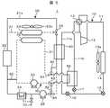
熱サイクルシステム1は、冷媒、例えばHFC−134aを循環して冷媒を圧縮,凝縮,膨張及び蒸発させるように冷媒循環路(一次循環路)11が形成されたヒートポンプ方式の冷凍サイクルシステム10と、冷凍サイクルシステム10に冷却用中間熱交換器路40を介して熱的に接続され、冷却用熱媒体、例えば水又は不凍液を循環してEV1000の発熱体22と熱交換するように冷却用熱媒体循環路(二次循環路)21が形成された冷却用熱移動システム20と、冷凍サイクルシステム10に空調用中間熱交換器路50を介して熱的に接続され、空調用熱媒体、例えば水又は不凍液を循環して車室内に導入される空気と熱交換するように空調用熱媒体循環路(二次循環路)31が形成された空調用熱移動システム30とを備えている。 The
冷凍サイクルシステム10は、圧縮機12,四方弁13,室外熱交換器14,膨張弁15,16,17,冷却用中間熱交換器40及び空調用中間熱交換器50が冷媒循環路11によって機械的に接続されることにより構成されている。 The
四方弁13の第1接続口には圧縮機12の吸入側が接続されている。四方弁13の第2接続口には圧縮機12の突出側が接続されている。四方弁13の第3接続口には室外熱交換器14の圧縮機12側が接続されている。室外熱交換器14の四方弁13側とは反対側には膨張弁15が接続されている。膨張弁15の室外熱交換器14側とは反対側の冷媒循環路11はその先において冷却用経路11aと空調用経路11bとに分岐されている。このため、膨張弁15の室外熱交換器14側とは反対側には冷却用経路11a用の膨張弁16及び空調用経路11b用の膨張弁17がそれぞれ接続されている。膨張弁16の膨張弁15側とは反対側には冷却用中間熱交換器40の圧縮機12側とは反対側が接続されている。膨張弁17の膨張弁15側とは反対側には空調用中間熱交換器50の四方弁13側とは反対側が接続されている。冷却用中間熱交換器40の膨張弁16側と反対側は圧縮機12の吸入側に接続されている。空調用中間熱交換器50の膨張弁17側とは反対側は四方弁13の第4接続口に接続されている。室外熱交換器14には、室外熱交換器14に外気を取り込むための電動式送風機である室外ファン14aが取り付けられている。 The suction side of the
このような接続構成によれば、圧縮機12,四方弁13,室外熱交換器14,膨張弁15,膨張弁16,冷却用中間熱交換器40,圧縮機12の順に環状に接続された第1の閉回路と、圧縮機12,四方弁13,室外熱交換器14,膨張弁15,膨張弁17,空調用中間熱交換器50,四方弁13,圧縮機12の順に環状に接続された第2の閉回路とが形成される。 According to such a connection configuration, the
圧縮機12は、圧縮によって冷媒を高温及び高圧のガス状媒体とする電動式流体機器である。四方弁2は、圧縮機12に吸入されて吐出される冷媒の流れ方向を切り替えるための切替器であり、冷媒の流れを、圧縮機12に冷媒を冷却用中間熱交換器40及び空調用中間熱交換器50側から吸入して室外熱交換器14側に吐出する方向と、圧縮機12に冷媒を室外熱交換器4及び冷却用中間熱交換器40側から吸入して空調用中間熱交換器50側に吐出する方向とに切り替える。室外熱交換器14は、室外ファン14aによって送風される空気(外気)と冷媒との間において高温側媒体から低温側媒体に熱移動させるための熱移動機器である。膨張弁15,16,17は、弁体の開度調整によって冷媒を減圧させて膨張させることにより冷媒の圧力を調整すると共に、冷媒の流量を調整する調整弁である。冷却用中間熱交換器40は、冷凍サイクルシステム10の冷媒と冷却用熱移動システム20の冷却用熱媒体との間において高温側媒体から低温側媒体に熱移動させるための熱移動機器である。空調用中間熱交換器50は、冷凍サイクルシステム10の冷媒と空調用熱移動システム30の空調用熱媒体との間において高温側媒体から低温側媒体に熱移動させるための熱移動機器である。 The
冷却用熱移動システム20は、冷却用室内熱交換器23,発熱体22,リザーバタンク24,循環ポンプ25,冷却用中間熱交換器40及び三方弁26が冷却用熱媒体循環路21によって機械的に接続されることにより構成されている。 The cooling
冷却用中間熱交換器40の一方側(冷却用熱媒体の流出側)には三方弁26の第1接続口が接続されている。三方弁26の第2接続口には冷却用室内熱交換器23の発熱体22側とは反対側(冷却用熱媒体の流入側)が接続されている。冷却用室内熱交換器23の三方弁26側とは反対側(冷却用熱媒体の流出側)には発熱体22が接続されている。発熱体22の冷却用室内熱交換器23側とは反対側には循環ポンプ25の吸込側が接続されている。循環ポンプ25の発熱体22側とは反対側(吐出側)には冷却用中間熱交換器40の他方側(冷却用熱媒体の流入側)が接続されている。冷却用室内熱交換器23と発熱体22との間と三方弁26の第3接続口との間には、冷却用室内熱交換器23をバイパスして冷却用熱媒体を流通させるためのバイパス路21aが接続されている。冷却用室内熱交換器23には、車室内に導入される空気、すなわち室内の空気(内気)或いは外から取り込んだ空気(外気)を取り込むための電動式送風機である室内ファン23aが取り付けられている。発熱体22と循環ポンプ25との間にはリザーバタンク24が接続されている。 The first connection port of the three-
このような接続構成によれば、循環ポンプ25,冷却用中間熱交換器40,三方弁26,冷却用室内熱交換器23,発熱体22,循環ポンプ25の順に環状に接続された第1の閉回路と、循環ポンプ25,冷却用中間熱交換器40,三方弁26,バイパス路21a,発熱体22,循環ポンプ25の順に環状に接続された第2の閉回路とが形成される。 According to such a connection configuration, the
冷却用室内熱交換器23は、冷却用熱媒体循環路21を循環する冷却用熱媒体と、室内ファン23aによって取り込んだ内気或いは外気との間において高温側媒体から低温側媒体に熱移動させるための熱移動機器である。循環ポンプ25は冷却用熱媒体循環路21の冷却用熱媒体を循環させるための電動式流体機器である。三方弁26は、弁体の切り替えによって冷却用熱媒体の流通経路を切り替える切替器であり、冷却用中間熱交換器40から流出した冷却用熱媒体の冷却用室内熱交換器23側への流通と、バイパス路21a側への流通とを切り替える。 The cooling
リザーバタンク24は、冷却用熱媒体の温度変化に伴う冷却用熱媒体循環路21内の圧力を調整するためのものであり、冷却用熱媒体の温度が高くなり冷却用熱媒体循環路21内の圧力が上昇した場合には、余分な冷却用熱媒体を貯める。冷却用熱媒体の温度が低くなり冷却用熱媒体循環路21内の圧力が降下した場合には、貯めてあった冷却用熱媒体は冷却用熱媒体循環路21に引き戻される。このような作用により、冷却用熱媒体循環路21内の圧力は常に規定値に保たれる。 The
発熱体22は、EV1000の電動機駆動システムのコンポーネントを示し、例えばバッテリ100,モータジェネレータ200及びインバータ装置300が冷却用熱媒体による温調対象になる。発熱体22としては、インバータ装置300以外の電力変換装置、例えば充電器500などに搭載されるDC/DCコンバータや、変速機構のギヤボックスなどを温調対象としても構わない。 The
ここで、発熱体22は、冷却用室内熱交換器23と循環ポンプ25との間に、冷却用熱媒体の上流(温度が低い状態)側から熱許容温度の低い順或いは熱時定数の小さい順に直列に配置することが好ましく、例えばバッテリ100,インバータ装置300及びモータジェネレータ200の順番に配置する。発熱体22の配置としては、冷却用室内熱交換器23と循環ポンプ25との間に、バッテリ100,インバータ装置300及びモータジェネレータ200を並列に配置しても構わない。 Here, the
また、発熱体22は、冷却用室内熱交換器23と循環ポンプ25との間に配置したが、冷却用中間熱交換器50と三方弁26との間に配置しても構わない。 Further, although the
空調用熱移動システム30は、空調用室内熱交換器32,循環ポンプ33及び空調用中間熱交換器50が空調用熱媒体循環路31によって機械的に接続されることにより構成されている。 The air conditioning
空調用中間熱交換器50の一方側(空調用熱媒体の流出側)には空調用室内熱交換器32の循環ポンプ33側とは反対側(空調用熱媒体の流入側)が接続されている。空調用室内熱交換器32の空調用中間熱交換器50側とは反対側(空調用熱媒体の流出側)には循環ポンプ33の吸込側が接続されている。循環ポンプ33の空調用室内熱交換器32側とは反対側(吐出側)には空調用中間熱交換器50の他方側(空調用熱媒体の流入側)が接続されている。 One side of the air conditioning intermediate heat exchanger 50 (the outflow side of the air conditioning heat medium) is connected to the side opposite to the
このような接続構成によれば、循環ポンプ33,空調用中間熱交換器50,空調用室内熱交換器32,循環ポンプ25の順に環状に接続された一つの閉回路が形成される。 According to such a connection configuration, one closed circuit is formed in which the
空調用室内熱交換器32は、空調用熱媒体循環路31を循環する空調用熱媒体と、室内ファン23aによって取り込んだ内気或いは外気との間において高温側媒体から低温側媒体に熱移動させるための熱移動機器である。循環ポンプ33は空調用熱媒体循環路31の空調用熱媒体を循環させるための電動式流体機器である。 The air conditioning
冷却用室内熱交換器23及び空調用室内熱交換器32は内気或いは外気の流れ方向の上流側から下流側に向かって空調用室内熱交換器32,冷却用室内熱交換器23の順に配置されている。室内ファン23aは冷却用室内熱交換器23及び空調用室内熱交換器32に対して共通に設けられており、内気或いは外気の流れ方向に対して冷却用室内熱交換器23及び空調用室内熱交換器32の配列よりも下流側に配置されている。 The
冷却用熱媒体循環路21と空調用熱媒体循環路31との間には連通路60が設けられている。連通路60は、空調用熱媒体の温度変化に伴う空調用熱媒体循環路31内の圧力調整を、冷却用熱媒体循環路21に接続されたリザーバタンク24を用いて行うために設けられたものである。すなわち冷却用熱移動システム20と空調用熱移動システム30とにおいてリザーバタンク24を共用化している。空調用熱媒体の温度が高くなり空調用熱媒体循環路31内の圧力が上昇した場合には、空調用熱媒体循環路31から連通路60を介して余分な空調用熱媒体が冷却用熱媒体循環路21に排出され、リザーバタンク24に貯められる。ここで、空調用熱媒体と冷却用熱媒体は同じものであり、水又は不凍液が用いられている。空調用熱媒体の温度が低くなり空調用熱媒体循環路31内の圧力が降下した場合には、貯めてあった空調用熱媒体がリザーバタンク24から冷却用熱媒体循環路21及び連通路60を介して空調用熱媒体循環路31に引き戻される。このような作用により、空調用熱媒体循環路31内の圧力は常に規定値に保たれる。 A
このように、本実施例では、冷却用熱移動システム20と空調用熱移動システム30とにおいてリザーバタンク24を共用化しているので、熱サイクルシステム1の部品点数を削減することができ、熱サイクルシステム1の構成を簡素化することができる。熱サイクルシステム1の構成の簡素化は、流路を構成する配管や構成部品が狭い設置スペース内において複雑に入り組むことが考えられる熱サイクルシステム1のメインテナンス性を向上させることができると共に、熱サイクルシステム1の小型化及び低コスト化に寄与することができる。 Thus, in this embodiment, since the
尚、リザーバタンク24は空調用熱媒体循環路31に設けられていてもよい。また、リザーバタンク24は発熱体22と循環ポンプ25との間の循環路とは異なる循環路上に設けられていてもよい。 The
また、本実施例では、冷却用熱媒体循環路21を循環する冷却用熱媒体と空調用熱媒体循環路31を循環する空調用熱媒体とを外部に排出するためのドレイン排出機構を、冷却用熱媒体循環路21の高さが最も低い部位に設けている。本実施例では、ドレイン排出機構を、冷却用熱媒体循環路21のリザーバタンク24と循環ポンプ25との間の循環路上に設けている。ドレイン排出機構は、冷却用熱媒体循環路21のリザーバタンク24と循環ポンプ25との間の循環路に接続されたドレイン排出路70、及びドレイン排出路70上に設けられたドレイン排出開閉弁71から構成されている。ドレイン排出開閉弁71は、冷却用熱媒体循環路21を循環する冷却用熱媒体と空調用熱媒体循環路31を循環する空調用熱媒体を交換するときに開かれ、通常は閉じられている。空調用熱媒体循環路31を循環する空調用熱媒体は連通路60を介して冷却用熱媒体循環路21に排出された後、ドレイン排出機構によって外部に排出される。このため、連通路60は、冷却用熱媒体循環路21及び空調用熱媒体循環路31の高さが最も低い部位において冷却用熱媒体循環路21及び空調用熱媒体循環路31を連通している。 Further, in this embodiment, the drain discharge mechanism for discharging the cooling heat medium circulating in the cooling heat
以上のような構成によれば、熱サイクルシステム1の部品点数をさらに削減して、熱サイクルシステム1の構成をさらに簡素化することができ、熱サイクルシステム1のメインテナンス性をさらに向上させることができると共に、熱サイクルシステム1の小型化及び低コスト化にさらに寄与することができる。 According to the above configuration, the number of parts of the
次に、熱サイクルシステム1の運転動作について、各運転モード毎に説明する。 Next, the operation of the
(冷房運転)
冷房運転とは、室外熱交換器14を凝縮器、空調用中間熱交換器50及び冷却用中間熱交換器40を蒸発器として用いて、空調用熱移動システム30により車室内の冷房を行うと共に、冷却用熱移動システム20により発熱体22の冷却を行う運転モードである。冷房運転の場合、図1に示すように、冷凍サイクルシステム10に設けられた四方弁13によって圧縮機12の吐出側が室外熱交換器14に接続され、圧縮機12の吸込側が空調用中間熱交換器50に接続される。また、圧縮機12の吸込側には冷却用中間熱交換器50が接続される。また、三方弁26によって冷却用熱媒体はバイパス路21aを流通する。(Cooling operation)
In the cooling operation, the
圧縮機12で圧縮され、高温及び高圧のガス状になった冷媒は、室外熱交換器14における外気との熱交換(放熱)によって液化された後、全開状態の膨張弁15を通過し、空調用中間熱交換器50へ流れる冷媒と冷却用中間熱交換器40へ流れる冷媒とに分岐される。空調用中間熱交換器50に流れる冷媒は、膨張弁17によって減圧されることにより低温・低圧の冷媒となり、空調用中間熱交換器50において空調用熱媒体循環路31の空調用熱媒体から吸熱することによって蒸発し、四方弁13を通って圧縮機12へ戻る。一方、冷却用中間熱交換器40へ流れる冷媒は、膨張弁16によって減圧されることにより低温・低圧の冷媒となり、冷却用中間熱交換器40において冷却用熱媒体循環路21の冷却用熱媒体から吸熱することによって蒸発し、圧縮機12へと戻る。 The refrigerant compressed in the
空調用熱媒体循環路31に設けられた循環ポンプ33を駆動すると、空調用中間熱交換器50において熱交換されて冷却された空調用熱媒体は空調用室内熱交換器32に供給される。そして、空調用熱媒体は、室内ファン23aの駆動によって室内に導入される空気と空調用室内熱交換器32において熱交換(空気の熱が空調用熱媒体に放熱)される。これにより、車室内には、冷却された空気が導入され、冷房される。 When the
また、冷却用熱媒体循環路21に設けられた循環ポンプ25を駆動すると、冷却用中間熱交換器40において熱交換されて冷却された冷却用熱媒体は三方弁26,バイパス路21aを介して発熱体22に供給される。そして、冷却用熱媒体は、発熱体22と熱交換(発熱体22の熱が冷却用熱媒体に放熱)される。これにより、発熱体22は冷却される。 Further, when the
このように、本実施例では、空調用中間熱交換器50及び冷却用中間熱交換器40の両方を蒸発器として利用できるので、車室内の冷房と発熱体22の冷却とを同時に実現することができる。さらに、空調用中間熱交換器50と冷却用中間熱交換器40とを圧縮機12の吸込側に対して並列に接続し、冷却用経路11a及び空調用経路11bのそれぞれに膨張弁16,17を設けているので、空調用中間熱交換器50及び冷却用中間熱交換器40へ流れる冷媒流量を、それぞれ任意に変えることができる。その結果、冷却用熱媒体の温度と空調用熱媒体の温度とを、それぞれ任意の所望の温度に制御することができる。従って、冷房を行うために空調用熱媒体の温度を十分下げた場合であっても、冷却用中間熱交換器40へ流れる冷媒流量を抑制することで、発熱体22が接続された冷却用熱媒体の温度を高く保つことができる。 Thus, in this embodiment, since both the air conditioning
ところで、発熱体22の表面温度が外気温度よりも低くなると、外気から発熱体22へ熱が入ってくることになる。従って、この入熱量分だけ冷凍サイクルシステム10に要求される冷却能力が増加することになり、消費電力が増加すると考えられる。これは、バッテリ100の使用量が増加することになるので、航続距離が低下に繋がると考えられる。また、外気の露点温度よりも低い場合には、結露を生じる恐れがあるので、結露に起因する不具合への対策が必要になる。このような課題は、配管経路においても同様であるため、冷却用熱媒体の温度を外気温度よりも高く保つことが望ましい。 By the way, when the surface temperature of the
尚、冷却用熱媒体の温度を制御するためには、膨張弁16の開度を制御すれば良く、簡易的には冷却用熱媒体の温度が高い場合に開度を開き、温度が低い場合には開度を絞るように制御すれば良い。 In order to control the temperature of the cooling heat medium, it is only necessary to control the opening degree of the
また、冷凍サイクルシステム10の能力を調整するためには、圧縮機12の回転数を制御すればよく、空調用熱媒体の温度が所望の温度となるように制御する。冷房負荷が大きいと判断した場合には、空調用熱媒体の制御目標温度を低くし、冷房負荷が小さいと判断した場合には、空調用熱媒体の制御目標温度を高くすることによって、負荷に応じた空調能力の制御が可能となっている。 Further, in order to adjust the capacity of the
尚、冷房負荷がなく、発熱体22の冷却のみが必要な場合には、循環ポンプ33及び室内ファン23aを停止するとともに、膨張弁17を閉じ、膨張弁16の開度を調整することによって、冷却用中間熱交換器40のみを蒸発器として利用すれば良い。これにより、冷却用熱媒体の冷却が可能となるので、発熱体22の冷却ができる。この場合、圧縮機12の回転数を冷却用熱媒体の温度が目標温度となるように制御する。このときの目標温度は、外気温度よりも高い温度に設定される。また、循環ポンプ25の回転数を制御することで、熱交換量を変化させても良い。 When there is no cooling load and only the cooling of the
(冷房除湿運転)
冷房除湿運転では、図1の状態から三方弁26によって、温度の高い冷却用熱媒体を冷却用室内熱交換器23側に流すようにする。このように、温度の高い冷却用熱媒体を冷却用室内熱交換器23に導入すると、空調用室内熱交換器32において冷却・除湿された空気が、冷却用室内熱交換器23によって加熱されてから車室内へ吹き出される、いわゆる再熱除湿運転が可能となる。車室内へ供給される空気は相対湿度が低くなるため、室内空間の快適性を向上できる。(Cooling dehumidification operation)
In the cooling and dehumidifying operation, a cooling heat medium having a high temperature is caused to flow toward the cooling
尚、再熱器として利用される冷却用室内熱交換器23の熱源は、発熱体22から発生するいわゆる排熱である。そのため、再熱用にヒータなどを用いる場合とは異なり、新たにエネルギーを投入する必要がないので、消費電力を増大させることなく車室内の快適性を向上させることが可能になる。 The heat source of the cooling
再熱量は、冷却用室内熱交換器23側に流れる冷却用熱媒体の温度と流量によって変化するので、冷却用中間熱交換器40の交換熱量や、冷却用室内熱交換器23側に流れる冷却用熱媒体の流量を変えることによって、再熱量を制御することができる。冷却用中間熱交換器40の交換熱量を可変とするためには、膨張弁16の開度を制御して、冷却用中間熱交換器40へ流れる冷媒流量を制御すれば良く、冷却が不要な場合には膨張弁16の開度を全閉とすれば良い。 Since the amount of reheat varies depending on the temperature and flow rate of the cooling heat medium flowing to the cooling
また、冷却用室内熱交換器23側への冷却用熱媒体の流量を可変とするためには、三方弁26の開閉状態を制御すれば良い。 In order to change the flow rate of the cooling heat medium toward the cooling
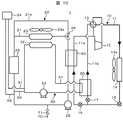
(暖房運転)
次に、図2を用いて、暖房運転時の動作を説明する。(Heating operation)
Next, the operation | movement at the time of heating operation is demonstrated using FIG.
暖房運転時には、暖房負荷に応じた2つの運転モードがある。 During the heating operation, there are two operation modes depending on the heating load.
暖房運転の一つ目の運転モードは、暖房負荷が小さい時の放熱運転モードであり、発熱体22からの排熱を暖房に利用することで、冷凍サイクルシステム10は暖房に利用しない。放熱運転モードでは、循環ポンプ25と室内ファン23aを起動し、かつ三方弁26によって冷却用室内熱交換器23側に冷却用熱媒体を流す。冷却用熱媒体は発熱体22によって加熱されているので、冷却用室内熱交換器23において室内吹出し空気へ放熱することによって、冷却用熱媒体は冷却され、室内吹出し空気が加熱される。このように発熱体22からの排熱を暖房に利用することで、エネルギー消費を抑えて空調を行うことができる。 The first operation mode of the heating operation is a heat radiation operation mode when the heating load is small, and the
暖房運転の二つ目の運転モードは、発熱体22の排熱だけでは暖房負荷に満たない場合の運転モードであって、発熱体22の排熱に加えて冷凍サイクルシステム10を併用する暖房放熱運転モードである。この場合、冷凍サイクルシステム10に設けられた四方弁13の切り替えによって、圧縮機12の吐出側を空調用中間熱交換器50に接続するとともに、吸込側を室外熱交換器14に接続する。すなわち空調用熱交換器41Aを凝縮器、室外熱交換器14を蒸発器とするサイクルが形成される。 The second operation mode of the heating operation is an operation mode when the exhaust heat of the
圧縮機12で圧縮された冷媒は、空調用中間熱交換器50において空調用熱媒体と熱交換して放熱することにより凝縮液化する。その後、膨張弁15により減圧された後、室外熱交換器14において室外空気との熱交換によって蒸発・ガス化して圧縮機12へと戻る。この時、膨張弁17は全開、膨張弁16は全閉となっており、冷却用中間熱交換器40は利用しない。 The refrigerant compressed by the
循環ポンプ33を起動することにより、空調用中間熱交換器50において冷媒の凝縮熱をもらって昇温された空調用熱媒体は空調用室内熱交換器32へ流入し、空調用室内熱交換器32において室内吹出し空気へ放熱する。空調用室内熱交換器32において加熱された空気は、空気の流れの下流側に配置された冷却用室内熱交換器23において、発熱体22によって加熱された冷却用熱媒体から熱をもらい、さらに昇温されてから室内空間へ吹き出される。 By starting the
このように、室内吹出し空気は、冷凍サイクルシステム10によって加熱された後に、発熱体22の排熱でさらに加熱される構成となっている。このため、空調用室内熱交換器32からの吹出し空気温度を、冷却用室内熱交換器23からの室内吹出し空気温度に対して低く保つことができる。すなわち発熱体22からの排熱を暖房に利用することによって、エネルギー消費の少ない空調装置を構成することができる。 As described above, the indoor blown air is heated by the
また、冷凍サイクルシステム10の暖房能力を制御することにより、発熱体22の発熱に応じて冷却用熱媒体の温度を制御することができる。発熱体22からの発熱量が増大した場合には、冷却用熱媒体の温度が上昇するので、冷凍サイクルシステム10の暖房能力を抑制する。これにより空調用室内熱交換器32からの放熱量が抑制され、冷却用室内熱交換器23へ流入する空気の温度が低くなるので、冷却用熱媒体からの放熱量が増大し、冷却用熱媒体の温度上昇が抑制される。 Further, by controlling the heating capacity of the
逆に、発熱体22からの発熱量が減少した場合には、冷却用熱媒体の温度が低下するので、冷凍サイクルシステム10の暖房能力を増大させ、冷却用室内熱交換器23に流入する空気の温度を上げることで、冷却用熱媒体の温度低下を抑制する。 Conversely, when the amount of heat generated from the
尚、冷凍サイクルシステム10の能力を制御するための具体例としては、圧縮機12の回転数を制御すれば良い。 In addition, what is necessary is just to control the rotation speed of the
また、冷却用熱媒体の温度を所定の温度域に保つ制御は、発熱体22の温度が使用可能な温度域から外れるなどの不具合を回避するうえでも有効である。 Control for keeping the temperature of the cooling heat medium in a predetermined temperature range is also effective in avoiding problems such as the temperature of the
(暖房冷却運転)
暖房負荷が大きな場合には、上述したように冷却用熱媒体の目標温度を高く設定すれば良いが、発熱体22の仕様等により温度を上げることが困難な場合には、暖房能力を増大させることができなくなる。このような場合には、以下に説明する暖房冷却運転を行い、冷却用熱媒体の冷却と空調用熱媒体の加熱を同時に実現する。(Heating / cooling operation)
When the heating load is large, the target temperature of the cooling heat medium may be set high as described above. However, when it is difficult to increase the temperature due to the specifications of the
暖房冷却運転では、暖房放熱併用運転と同様に、空調用中間熱交換器50を凝縮器、室外熱交換器14を蒸発器とするサイクルを構成し、さらに膨張弁16を開けて、冷却用中間熱交換器40を蒸発器として利用する。空調用中間熱交換器50において凝縮・液化した冷媒は、膨張弁17を通過した後、分岐し、一方が膨張弁23で減圧された後、室外熱交換器14で蒸発して圧縮機1へ戻る。他方は膨張弁16で減圧され、冷却用中間熱交換器40で冷却用熱媒体を冷却することによって蒸発・ガス化し、三方弁21を介して圧縮機1へと戻る。 In the heating / cooling operation, similarly to the heating / heat radiation combined use operation, a cycle in which the air-conditioning
暖房冷却運転では、発熱体22からの排熱は、冷却用中間熱交換器40において冷凍サイクルシステム10の熱源として回収され、空調用中間熱交換器50を介して空調用室内熱交換器32から車室内へ放熱される。このように、発熱体22の温度を抑制しながら発熱体22の排熱を回収して暖房に利用することが可能となっている。さらに、室外熱交換器14を用いて外気から吸熱することが可能となっているので、暖房能力を増大させることができる。 In the heating / cooling operation, the exhaust heat from the
また、膨張弁16と膨張弁23の開度をそれぞれ制御することによって、冷却用熱媒体からの吸熱量と外気からの吸熱量を個別に制御することが可能である。 Further, by controlling the opening degree of the
尚、冷却用熱媒体の温度が、空調用熱媒体の温度よりも低くなると、空調用室内熱交換器32において加熱した空気を、冷却用室内熱交換器23において冷却してしまうので、このような場合には、冷却用熱媒体循環路21において三方弁26を操作して、バイパス路21aを利用することで、冷却用中間熱交換器40において冷却された冷却用熱媒体によって、室内吹出し空気が冷却されることを防止できる。 If the temperature of the cooling heat medium becomes lower than the temperature of the air conditioning heat medium, the air heated in the air conditioning
暖房冷却運転から暖房負荷が下がり、暖房放熱併用運転に移行する場合に、冷却用熱媒体の温度が低いと吹出し温度が低いなどの不具合が生じる可能性があるので、移行する前に冷却用熱媒体の温度を上げておくことが望ましい。冷却用熱媒体の温度は冷却用中間熱交換器40の熱交換量を可変とすることで制御することができるので、膨張弁16の開度を制御すれば良い。 When the heating load is lowered from the heating / cooling operation and the operation is shifted to the combined heating / heat radiation operation, there is a possibility that problems such as a low blow-out temperature may occur if the temperature of the cooling heat medium is low. It is desirable to raise the temperature of the medium. Since the temperature of the cooling heat medium can be controlled by making the heat exchange amount of the cooling
尚、暖房冷却運転中も機器冷却媒体の温度を高く保ち、空調用熱媒体の温度が冷却用熱媒体の温度よりも下がったことを検知した場合には、暖房負荷が下がったと判断することができるので、暖房冷却運転から暖房放熱併用運転へ移行することができる。 In addition, during the heating / cooling operation, the temperature of the equipment cooling medium is kept high, and when it is detected that the temperature of the air conditioning heat medium is lower than the temperature of the cooling heat medium, it may be determined that the heating load has decreased. Therefore, it is possible to shift from the heating / cooling operation to the heating / radiation combined operation.
(加熱運転)
外気温度の低い冬季の始動時などでは、冷却用熱媒体の温度が低く運転開始直後は暖房に供することができず、発熱体22からの排熱による温度上昇を待つ必要がある。このような場合には、膨張弁16を閉とし、空調用室内熱交換器32による暖房運転を行う。また、三方弁26を操作し、冷却用室内熱交換器23において温度の低い冷却用熱媒体と室内へ吹き出す風とが熱交換することのないようにサイクルを構成する。(Heating operation)
At the time of start-up in winter when the outside air temperature is low, the temperature of the cooling heat medium is low and cannot be used for heating immediately after the start of operation, and it is necessary to wait for a temperature rise due to exhaust heat from the
また、発熱体22の温度が低温側の許容温度よりも低い場合には、冷却用中間熱交換機40において冷却用熱媒体を暖め、この暖められた冷却用熱媒体を三方弁26及びバイパス路21aを介して発熱体22に供給し、発熱体22をEV1000の始動開始直前に予め暖気しておく。この場合、始動時間設定システムに始動開始時間を予め設定しておき、その設定時間の所定時間前に、熱サイクルシステム1を作動させ、上記加熱運転を行う。このようにすれば、発熱体22をEV1000の始動時から効率良く作動させることができ、要求トルクに対応したトルクをモータジェネレータ200から供給して、EV1000を走行させることができる。 When the temperature of the
EV1000に搭載される熱サイクルシステム1の第2実施例を図4及び図5に基づいて説明する。 A second embodiment of the
第2実施例は第1実施例の改良例であり、冷却用熱媒体循環路21の一部に対して空調用熱媒体循環路31の一部を直列に接続できるように循環路接続制御部を設け、冷却用熱媒体循環路21を流通する熱媒体が、空調用中間熱交換器50と冷却用中間熱交換器40とを直列に流通できるようにしている。 The second embodiment is an improved example of the first embodiment, and a circulation path connection control unit so that a part of the air conditioning heat
尚、第1実施例と同様の構成には第1実施例と同様の符号を付し、その説明を省略する。 In addition, the same code | symbol as 1st Example is attached | subjected to the structure similar to 1st Example, and the description is abbreviate | omitted.
循環路接続制御部は、循環ポンプ25と冷却用中間熱交換器40との間の循環路上に設けられた三方弁84,循環ポンプ33と空調用中間熱交換器50との間の循環路上に設けられた三方弁83,空調用中間熱交換器50と空調用室内熱交換器32との間の循環路上に設けられた三方弁81,三方弁84と三方弁83との間を接続する接続路82、及び三方弁84と冷却用中間熱交換器40との間の循環路と三方弁83との間を接続する接続路80から構成されている。 The circulation path connection control unit is provided on the circulation path between the three-
三方弁81の第1接続口には空調用中間熱交換器50の一方側(空調用熱媒体の流出側)が接続されている。三方弁81の第2接続口には空調用室内熱交換器32の空調用中間熱交換器50側(空調用熱媒体の流入側)が接続されている。三方弁81の第3接続口には接続路80が接続されている。三方弁83の第1接続口には循環ポンプ33の吐出側が接続されている。三方弁83の第2接続口には空調用中間熱交換器50の他方側(空調用熱媒体の流入側)が接続されている。三方弁83の第3接続口には接続路82が接続されている。三方弁84の第1接続口には循環ポンプ25の吐出側が接続されている。三方弁84の第2接続口には冷却用中間熱交換器40の一方側(冷却用熱媒体の流入側)が接続されている。三方弁84の第3接続口には接続路82が接続されている。 One side of the air conditioning intermediate heat exchanger 50 (the outflow side of the air conditioning heat medium) is connected to the first connection port of the three-
三方弁81,83,84は、発熱体22に供給される冷却用熱媒体の冷媒との熱交換量を、冷却用中間熱交換器40のみにおいて冷媒と熱交換するときよりも大きくし、発熱体22の温調(冷却)能力を大きくしたいときに、流体の流れ方向を切り替えるための機構が駆動され、冷却用熱媒体の流通方向を切り替える。 The three-
ここで、第1実施例における各運転モードにある場合(図4の場合)には、三方弁81,83,84は、接続路80,82に冷却用熱媒体が流通しないような状態、すなわちそれぞれ第1接続口から第2接続口の方向に冷却用熱媒体を流通させる状態になっている。 Here, in each operation mode in the first embodiment (in the case of FIG. 4), the three-
発熱体22に供給される冷却用熱媒体の冷媒との熱交換量が、冷却用中間熱交換器40のみにおいて冷媒と熱交換するときよりも大きくなり、発熱体22の温調(冷却)能力が大きくなるように、三方弁81,83,84の切替機構が駆動されると、すなわち三方弁81は第1接続口から第3接続口の方向に、三方弁83は第3接続口から第2接続口の方向に、三方弁84は第1接続口から第3接続口の方向に、それぞれ冷却用媒体が流れるように切り替わると(図5の場合)、循環ポンプ25によって送圧された冷却用熱媒体は、三方弁84,接続路82,三方弁83を介して空調用中間熱交換器50に供給されて冷媒と熱交換され、この後、三方弁81,接続路80を介して冷却用中間熱交換器40に供給されて冷媒と熱交換される。 The amount of heat exchange with the refrigerant of the cooling heat medium supplied to the
尚、図5では、冷却用熱媒体が流れる流路は実線にて、熱媒体が流れない流路は破線にてそれぞれ示している。 In FIG. 5, the flow path through which the cooling heat medium flows is indicated by a solid line, and the flow path through which the heat medium does not flow is indicated by a broken line.
第2実施例によれば、空調用中間熱交換器50,冷却用中間熱交換器40の順に直列に冷却用熱媒体を流通させることにより、冷却用熱媒体と冷媒との熱交換量(冷却用熱媒体の冷却量)を第1実施例よりも大きくでき、発熱体22の冷却能力を第1実施例よりも大きくできる。 According to the second embodiment, the amount of heat exchange between the cooling heat medium and the refrigerant (cooling) is made by circulating the cooling heat medium in series in the order of the air conditioning
この場合、車室内の冷房は不可能となるが、車室内の冷房と両立させたい場合には、三方弁26に代えて流量調節弁を2個設置し、すなわちバイパス路21a上と冷却用室内熱交換器23側に至る循環路上にそれぞれ流量調整弁を設置し、冷却用室内熱交換器23側に流れる冷却用熱媒体及びバイパス路21aを流れる冷却用熱媒体の流量を調節すればよい。 In this case, the cooling of the passenger compartment becomes impossible, but when it is desired to achieve both the cooling of the passenger compartment, two flow control valves are installed instead of the three-
EV1000に搭載される熱サイクルシステム1の第3実施例を図6及び図7に基づいて説明する。 A third embodiment of the
第3実施例は第1実施例の改良例であり、冷却用熱媒体循環路21を発熱体22、例えばバッテリ100及びインバータ装置300に、空調用熱媒体循環路31を、発熱体22のグループから外した発熱体27、例えばモータジェネレータ200に、それぞれ接続できるように循環路接続切替部を設け、冷却用熱媒体循環路21を循環する冷却用熱媒体を発熱体22に、空調用熱媒体循環路31を循環する空調用熱媒体を発熱体27に、それぞれ流通できるようにしている。 The third embodiment is an improved example of the first embodiment, in which the cooling heat
尚、第1実施例と同様の構成には第1実施例と同様の符号を付し、その説明を省略する。 In addition, the same code | symbol as 1st Example is attached | subjected to the structure similar to 1st Example, and the description is abbreviate | omitted.
循環路接続切替部は、空調用中間熱交換器50と空調用室内熱交換器32との間の循環路上に設けられた三方弁94,空調用室内熱交換器32と循環ポンプ33との間の循環路上に設けられた三方弁91,発熱体27と循環ポンプ25との間の循環路上に設けられた三方弁92,リザーバタンク24と発熱体27との循環路上に設けられた四方弁95,三方弁91と三方弁92との間を接続する接続路90,三方弁94と四方弁95との間を接続する接続路93、及び三方弁92と循環ポンプ25との間の循環路と四方弁95との間を接続する接続路96から構成されている。 The circulation path connection switching unit is provided between the three-
三方弁94の第1接続口には空調用中間熱交換器50の一方側(空調用熱媒体の流出側)が接続されている。三方弁94の第2接続口には空調用室内熱交換器32の空調用中間熱交換器50側(空調用熱媒体の流入側)が接続されている。三方弁94の第3接続口には接続路93が接続されている。三方弁91の第1接続口には空調用室内熱交換器32の一方側(空調用熱媒体の流出側)が接続されている。三方弁91の第2接続口には循環ポンプ33の吸込側が接続されている。三方弁91の第3接続口には接続路90が接続されている。三方弁92の第1接続口には発熱体27の循環ポンプ25側が接続されている。三方弁92の第2接続口には循環ポンプ25の吸込側が接続されている。三方弁92の第3接続口には接続路90が接続されている。四方弁95の第1接続口はリザーバタンク24の発熱体22側とは反対側が接続されている。四方弁95の第2接続口には発熱体27の三方弁92側とは反対側が接続されている。四方弁95の第3接続口には接続路93が接続されている。四方弁95の第4接続口には接続路96が接続されている。 One side of the air conditioning intermediate heat exchanger 50 (outflow side of the air conditioning heat medium) is connected to the first connection port of the three-
三方弁91,92,94及び四方弁95は、発熱体22,27と熱媒体との間の熱交換量を、発熱体22,27と冷却用熱媒体との間の熱交換量よりも大きくし、発熱体22,27の温調(冷却)能力を大きくしたいときに、流体の流れ方向を切り替えるための機構が駆動され、発熱体22,27のそれぞれに供給される熱媒体を変える。 The three-
ここで、第1実施例における各運転モードにある場合(図6の場合)には、三方弁91,92,94及び四方弁95は、接続路90,93,96に熱媒体が流通しないような状態、すなわちそれぞれ第1接続口から第2接続口の方向に冷却用熱媒体を流通させる状態になっている。 Here, in each operation mode in the first embodiment (in the case of FIG. 6), the three-
発熱体22,27と熱媒体との熱交換量が、発熱体22,27と冷却用熱媒体との間の熱交換量よりも大きくなり、発熱体22,27の温調(冷却)能力が大きくなるように、三方弁91,92,94及び四方弁95の切替機構が駆動されると、すなわち三方弁91は第1接続口から第3接続口の方向に、三方弁92は第1接続口から第3接続口の方向に、三方弁91は第3接続口から第2接続口の方向に、四方弁95は第1接続口から第4接続口の方向と第3接続口から第2接続口の方法に、それぞれ熱媒体が流れるように切り替わると(図7の場合)、循環ポンプ25によって送圧された冷却用熱媒体は、冷却用中間熱交換器40に供給されて冷媒と熱交換され、この後、三方弁26,バイパス路21aを介して発熱体22に供給されて発熱体22と熱交換され、この後、リザーバタンク24,四方弁95,接続路96を介して循環ポンプ25に循環される。一方、循環ポンプ33によって送圧された空調用熱媒体は、空調用中間熱交換器50に供給されて冷媒と熱交換され、この後、三方弁94,接続路93,四方弁95を解して発熱体27に供給されて発熱体27と熱交換され、この後、三方弁92,接続路90,三方弁91を介して循環ポンプ33に循環される。 The amount of heat exchange between the
尚、図7では、熱媒体が流れる流路は実線にて、熱媒体が流れない流路は破線にてそれぞれ示している。 In FIG. 7, the flow path through which the heat medium flows is indicated by a solid line, and the flow path through which the heat medium does not flow is indicated by a broken line.
第3実施例によれば、冷却用熱媒体を発熱体22に、空調用熱媒体を発熱体27に、それぞれ流通させることにより、熱媒体と発熱体との熱交換量(熱媒体の冷却量)を第1実施例よりも大きくでき、発熱体22,27の冷却能力を第1実施例よりも大きくできる。 According to the third embodiment, the amount of heat exchange between the heat medium and the heat generator (the amount of cooling of the heat medium) is made by circulating the heat medium for cooling to the
この場合、車室内の冷房は不可能となるが、車室内の冷房と両立させたい場合には、三方弁94に代えて流量調整弁を2個設置すると共に、三方弁91に代えて流量調整弁を2個設置し、すなわち空調用室内熱交換器32側に至る循環路上と、接続路93と、接続路90と、空調用室内熱交換32から循環ポンプ33に至る循環路上の接続路90よりも上流側にそれぞれ流量調整弁を設置し、空調用室内熱交換器23側に流れる空調用熱媒体及び接続路93側に流れる空調用熱媒体の流量を調節すればよい。また、冷房能力が不足することを考慮して、三方弁26に代えて流量調節弁を2個設置し、すなわちバイパス路21a上と冷却用室内熱交換器23側に至る循環路上にそれぞれ流量調整弁を設置し、冷却用室内熱交換器23側に流れる冷却用熱媒体及びバイパス路21aを流れる冷却用熱媒体の流量を調節するようにしてもよい。 In this case, the cooling of the passenger compartment becomes impossible, but when it is desired to achieve both the cooling of the passenger compartment, two flow control valves are installed in place of the three-
尚、第3実施例ではリザーバタンク24を発熱体22と四方弁95との間の循環路上に設けたが、それとは異なる循環路上に設けてもよい。 In the third embodiment, the
EV1000に搭載される熱サイクルシステム1の第4実施例を図8に基づいて説明する。 A fourth embodiment of the
第4実施例は第1実施例の変形例であり、冷房運転と冷房除湿運転のみ可能としたシステム構成になっている。すなわち第1実施例では、四方弁13にて冷媒の流れ方向を冷房と暖房で切り換えていたが、本実施例では、圧縮機12の吐出側が室外熱交換器14側に接続され、吸入側が冷却用中間熱交換器40及び空調用中間熱交換器50側に接続されており、切り換え不可能な、固定された接続構成になっている。このような構成は、暖房を必要としない地域向けのEV1000として、熱サイクルシステム1の簡素化に適している。 The fourth embodiment is a modification of the first embodiment, and has a system configuration in which only a cooling operation and a cooling and dehumidifying operation are possible. That is, in the first embodiment, the refrigerant flow direction is switched between cooling and heating in the four-
尚、第1実施例と同様の構成には第1実施例と同様の符号を付し、その説明を省略する。 In addition, the same code | symbol as 1st Example is attached | subjected to the structure similar to 1st Example, and the description is abbreviate | omitted.
EV1000に搭載される熱サイクルシステム1の第5実施例を図9に基づいて説明する。 A fifth embodiment of the
第5実施例は第4実施例の改良例であり、冷却用熱媒体循環路21のリザーバタンク24と循環ポンプ25との間に、室外熱交換器28及び室外ファン28aを備えた熱交換ユニットを設置している。このようにすれば、冷凍サイクルシステム10に不具合があった場合、その熱交換ユニットによって冷却用熱媒体を冷却し、その冷却用熱媒体による発熱体22の冷却を継続できるので、発熱体22の作動によるEV1000の運転を継続できる。 The fifth embodiment is an improvement of the fourth embodiment, and includes a heat exchange unit including an
尚、第4実施例と同様の構成には第4実施例と同様の符号を付し、その説明を省略する。 In addition, the same code | symbol as 4th Example is attached | subjected to the structure similar to 4th Example, and the description is abbreviate | omitted.
また、第5実施例の構成は、他の実施例にも適用できる。 Further, the configuration of the fifth embodiment can be applied to other embodiments.
EV1000に搭載される熱サイクルシステム1の第6実施例を図10に基づいて説明する。 A sixth embodiment of the
第6実施例は第1実施例の変形例であり、リザーバタンク24を冷却用熱媒体循環路21及び空調用熱媒体循環路31の高さが最も高い部位よりも高い位置に設置すると共に、リザーバタンク24と冷却用熱媒体循環路21とを接続路61により接続し、リザーバタンク24と空調用熱媒体循環路31とを接続路62により接続している。このような構成によれば第1実施例と同様の機能を達成することができる。従って、第6実施例においても第1実施例と同様の効果を奏することができる。 The sixth embodiment is a modification of the first embodiment, and the
尚、第1実施例と同様の構成には第1実施例と同様の符号を付し、その説明を省略する。 In addition, the same code | symbol as 1st Example is attached | subjected to the structure similar to 1st Example, and the description is abbreviate | omitted.
また、第6実施例の構成は、他の実施例にも適用できる。 Further, the configuration of the sixth embodiment can be applied to other embodiments.
Claims (12)
Translated fromJapanese発熱体の温度を調整する熱媒体が流通する第1熱移動システムと、
室内の空気状態を調整する熱媒体が流通する第2熱移動システムと、
前記冷凍サイクルシステムと前記第1熱移動媒体システムとの間に設けられ、前記冷媒と前記熱媒体とを熱交換する第1中間熱交換器と、
前記冷凍サイクルシステムと前記第2熱移動媒体システムとの間に設けられ、前記冷媒と前記熱媒体とを熱交換する第2中間熱交換器と、
前記第1熱移動システムに設けられ、室内に取り込まれる空気と前記熱媒体とを熱交換する第1室内熱交換器と、
前記第2熱移動システムに設けられ、室内に取り込まれる空気と前記熱媒体とを熱交換する第2室内熱交換器と、
前記第1熱移動システム及び前記第2移動システムの熱媒体が流れる流路内の圧力を調整するためのリザーバタンクと、有し、
前記リザーバタンクは、前記第1熱移動システム及び前記第2移動システムに対して共通に設けられている、
ことを特徴とする移動体熱サイクルシステム。A refrigeration cycle system through which refrigerant flows;
A first heat transfer system in which a heat medium for adjusting the temperature of the heating element circulates;
A second heat transfer system in which a heat medium for adjusting the indoor air condition flows;
A first intermediate heat exchanger provided between the refrigeration cycle system and the first heat transfer medium system for exchanging heat between the refrigerant and the heat medium;
A second intermediate heat exchanger provided between the refrigeration cycle system and the second heat transfer medium system for exchanging heat between the refrigerant and the heat medium;
A first indoor heat exchanger provided in the first heat transfer system for exchanging heat between the air taken into the room and the heat medium;
A second indoor heat exchanger provided in the second heat transfer system for exchanging heat between the air taken into the room and the heat medium;
A reservoir tank for adjusting a pressure in a flow path through which a heat medium of the first heat transfer system and the second heat transfer system flows,
The reservoir tank is provided in common for the first heat transfer system and the second transfer system.
A moving body thermal cycle system characterized by that.
前記リザーバタンクは、前記第1熱移動システムの熱媒体流路及び前記第2移動システムの熱媒体流路のそれぞれに接続されている、
ことを特徴とする移動体熱サイクルシステム。The moving body thermal cycle system according to claim 1,
The reservoir tank is connected to each of the heat medium flow path of the first heat transfer system and the heat medium flow path of the second transfer system,
A moving body thermal cycle system characterized by that.
前記リザーバタンクは、前記第1熱移動システムの熱媒体流路或いは前記第2移動システムの熱媒体流路のいずれか一方に設けられており、
前記第1熱移動システムの熱媒体流路及び前記第2移動システムの熱媒体流路は連通路によって連通されている、
ことを特徴とする移動体熱サイクルシステム。The moving body thermal cycle system according to claim 1,
The reservoir tank is provided in either the heat medium flow path of the first heat transfer system or the heat medium flow path of the second transfer system,
The heat medium flow path of the first heat transfer system and the heat medium flow path of the second transfer system are communicated by a communication path.
A moving body thermal cycle system characterized by that.
前記第1熱移動システムの熱媒体流路及び前記第2移動システムの熱媒体流路から熱媒体を外部に排出するためのドレイン機構を有し、
前記ドレイン機構は、前記第1熱移動システム及び前記第2移動システムに対して共通に設けられている、
ことを特徴とする移動体熱サイクルシステム。The moving body thermal cycle system according to any one of claims 1 to 3,
A drain mechanism for discharging the heat medium from the heat medium flow path of the first heat transfer system and the heat medium flow path of the second movement system;
The drain mechanism is provided in common for the first heat transfer system and the second transfer system.
A moving body thermal cycle system characterized by that.
前記熱媒体と外気とを熱交換するための室外熱交換器を前記第1熱移動システムに設けた、
ことを特徴とする移動体熱サイクルシステム。The moving body thermal cycle system according to any one of claims 1 to 4,
An outdoor heat exchanger for exchanging heat between the heat medium and outside air is provided in the first heat transfer system,
A moving body thermal cycle system characterized by that.
発熱体の温度を調整する熱媒体が流通する第1熱移動システムと、
室内の空気状態を調整する熱媒体が流通する第2熱移動システムと、
前記冷凍サイクルシステムと前記第1熱移動媒体システムとの間に設けられ、前記冷媒と前記熱媒体とを熱交換する第1中間熱交換器と、
前記冷凍サイクルシステムと前記第2熱移動媒体システムとの間に設けられ、前記冷媒と前記熱媒体とを熱交換する第2中間熱交換器と、
前記第1熱移動システムに設けられ、室内に取り込まれる空気と前記熱媒体とを熱交換する第1室内熱交換器と、
前記第2熱移動システムに設けられ、室内に取り込まれる空気と前記熱媒体とを熱交換する第2室内熱交換器と、
前記発熱体に供給される熱媒体を前記第1及び前記第2中間熱交換器に直列に流通させるように、前記第1熱移動体システムの流路と前記第2熱移動体システムの流路との接続を制御するための流路接続制御部と、を有する、
ことを特徴とする移動体熱サイクルシステム。A refrigeration cycle system through which refrigerant flows;
A first heat transfer system in which a heat medium for adjusting the temperature of the heating element circulates;
A second heat transfer system in which a heat medium for adjusting the indoor air condition flows;
A first intermediate heat exchanger provided between the refrigeration cycle system and the first heat transfer medium system for exchanging heat between the refrigerant and the heat medium;
A second intermediate heat exchanger provided between the refrigeration cycle system and the second heat transfer medium system for exchanging heat between the refrigerant and the heat medium;
A first indoor heat exchanger provided in the first heat transfer system for exchanging heat between the air taken into the room and the heat medium;
A second indoor heat exchanger provided in the second heat transfer system for exchanging heat between the air taken into the room and the heat medium;
The flow path of the first heat transfer body system and the flow path of the second heat transfer body system so that the heat medium supplied to the heating element flows in series to the first and second intermediate heat exchangers. A flow path connection control unit for controlling connection with
A moving body thermal cycle system characterized by that.
前記発熱体に供給される熱媒体と前記冷媒との熱交換量を、前記第1中間熱交換において前記発熱体に供給される熱媒体と前記冷媒とを熱交換させるときよりも大きくしたいとき、前記流路接続制御部により、前記第1熱移動体システムの流路と前記第2熱移動体システムの流路との接続を制御する、
ことを特徴とする移動体熱サイクルシステム。The thermal cycle system according to claim 6, wherein
When it is desired to increase the amount of heat exchange between the heat medium supplied to the heating element and the refrigerant, compared to when heat exchange is performed between the heat medium supplied to the heating element and the refrigerant in the first intermediate heat exchange, The flow path connection control unit controls connection between the flow path of the first heat transfer body system and the flow path of the second heat transfer body system.
A moving body thermal cycle system characterized by that.
少なくとも二つの発熱体の温度を調整する熱媒体が流通する第1熱移動システムと、
室内の空気状態を調整する熱媒体が流通する第2熱移動システムと、
前記冷凍サイクルシステムと前記第1熱移動媒体システムとの間に設けられ、前記冷媒と前記熱媒体とを熱交換する第1中間熱交換器と、
前記冷凍サイクルシステムと前記第2熱移動媒体システムとの間に設けられ、前記冷媒と前記熱媒体とを熱交換する第2中間熱交換器と、
前記第1熱移動システムに設けられ、室内に取り込まれる空気と前記熱媒体とを熱交換する第1室内熱交換器と、
前記第2熱移動システムに設けられ、室内に取り込まれる空気と前記熱媒体とを熱交換する第2室内熱交換器と、
前記少なくとも二つの発熱体の一方に前記第1熱移動システムを流れる熱媒体を流通させ、前記少なくとも二つの発熱体の他方に前記第2熱移動システムを流れる熱媒体を流通させるように、前記少なくとも二つの発熱体と前記第1及び第2熱移動体システムの流路との接続を切り替えるための流路接続切替部と、を有する、
ことを特徴とする移動体熱サイクルシステム。A refrigeration cycle system through which refrigerant flows;
A first heat transfer system in which a heat medium for adjusting the temperature of at least two heating elements flows;
A second heat transfer system in which a heat medium for adjusting the indoor air condition flows;
A first intermediate heat exchanger provided between the refrigeration cycle system and the first heat transfer medium system for exchanging heat between the refrigerant and the heat medium;
A second intermediate heat exchanger provided between the refrigeration cycle system and the second heat transfer medium system for exchanging heat between the refrigerant and the heat medium;
A first indoor heat exchanger provided in the first heat transfer system for exchanging heat between the air taken into the room and the heat medium;
A second indoor heat exchanger provided in the second heat transfer system for exchanging heat between the air taken into the room and the heat medium;
At least one of the at least two heating elements is circulated through the first heat transfer system and the other of the at least two heating elements is circulated through the second heat transfer system. A flow path connection switching unit for switching the connection between the two heating elements and the flow paths of the first and second heat transfer body systems,
A moving body thermal cycle system characterized by that.
前記少なくとも二つの発熱体に供給される熱媒体と前記前記少なくとも二つの発熱体との間の熱交換量を、前記少なくとも二つの発熱体と前記第1熱移動システムの熱媒体との間の熱交換量よりも大きくしたいとき、前記流路接続切替部により、前記少なくとも二つの発熱体と前記第1及び第2熱移動体システムの流路との接続を切り替える、
ことを特徴とする移動体熱サイクルシステム。The mobile thermal cycle system according to claim 8,
The amount of heat exchange between the heat medium supplied to the at least two heat generating elements and the at least two heat generating elements is the heat exchange between the at least two heat generating elements and the heat medium of the first heat transfer system. When it is desired to make it larger than the exchange amount, the flow path connection switching unit switches the connection between the at least two heating elements and the flow paths of the first and second heat transfer body systems.
A moving body thermal cycle system characterized by that.
前記第1熱移動システム及び前記第2移動システムの熱媒体が流れる流路内の圧力を調整するためのリザーバタンクと、有し、
前記リザーバタンクは、前記第1熱移動システム及び前記第2移動システムに対して共通に設けられている、
ことを特徴とする移動体熱サイクルシステム。The moving body thermal cycle system according to any one of claims 6 to 9,
A reservoir tank for adjusting a pressure in a flow path through which a heat medium of the first heat transfer system and the second heat transfer system flows,
The reservoir tank is provided in common for the first heat transfer system and the second transfer system.
A moving body thermal cycle system characterized by that.
前記第1熱移動システムの熱媒体流路及び前記第2移動システムの熱媒体流路から熱媒体を外部に排出するためのドレイン機構を有し、
前記ドレイン機構は、前記第1熱移動システム及び前記第2移動システムに対して共通に設けられている、
ことを特徴とする移動体熱サイクルシステム。The moving body thermal cycle system according to any one of claims 6 to 10,
A drain mechanism for discharging the heat medium from the heat medium flow path of the first heat transfer system and the heat medium flow path of the second movement system;
The drain mechanism is provided in common for the first heat transfer system and the second transfer system.
A moving body thermal cycle system characterized by that.
前記熱媒体と外気とを熱交換するための室外熱交換器を前記第1熱移動システムに設けた、
ことを特徴とする移動体熱サイクルシステム。The moving body thermal cycle system according to any one of claims 6 to 11,
An outdoor heat exchanger for exchanging heat between the heat medium and outside air is provided in the first heat transfer system,
A moving body thermal cycle system characterized by that.
Priority Applications (4)
| Application Number | Priority Date | Filing Date | Title |
|---|---|---|---|
| JP2009270979AJP2011112312A (en) | 2009-11-30 | 2009-11-30 | Heat cycle system of moving body |
| CN2010800348236ACN102472531A (en) | 2009-11-30 | 2010-08-25 | Thermal cycle system for mobile object |
| US13/388,707US20120222441A1 (en) | 2009-11-30 | 2010-08-25 | Heat Cycle System for Mobile Object |
| PCT/JP2010/064390WO2011065075A1 (en) | 2009-11-30 | 2010-08-25 | Thermal cycle system for mobile object |
Applications Claiming Priority (1)
| Application Number | Priority Date | Filing Date | Title |
|---|---|---|---|
| JP2009270979AJP2011112312A (en) | 2009-11-30 | 2009-11-30 | Heat cycle system of moving body |
Publications (1)
| Publication Number | Publication Date |
|---|---|
| JP2011112312Atrue JP2011112312A (en) | 2011-06-09 |
Family
ID=44066178
Family Applications (1)
| Application Number | Title | Priority Date | Filing Date |
|---|---|---|---|
| JP2009270979APendingJP2011112312A (en) | 2009-11-30 | 2009-11-30 | Heat cycle system of moving body |
Country Status (4)
| Country | Link |
|---|---|
| US (1) | US20120222441A1 (en) |
| JP (1) | JP2011112312A (en) |
| CN (1) | CN102472531A (en) |
| WO (1) | WO2011065075A1 (en) |
Cited By (14)
| Publication number | Priority date | Publication date | Assignee | Title |
|---|---|---|---|---|
| WO2013077133A1 (en)* | 2011-11-21 | 2013-05-30 | 日立オートモティブシステムズ株式会社 | Cooling device |
| WO2013084465A1 (en)* | 2011-12-05 | 2013-06-13 | 株式会社デンソー | Heat exchange system |
| JP2013154805A (en)* | 2012-01-31 | 2013-08-15 | Denso Corp | Vehicle air conditioning system |
| JP2013199237A (en)* | 2012-03-26 | 2013-10-03 | Panasonic Corp | Air conditioning device for vehicle |
| WO2014016865A1 (en)* | 2012-07-24 | 2014-01-30 | 三菱電機株式会社 | Air-conditioning device |
| WO2014034062A1 (en)* | 2012-08-28 | 2014-03-06 | 株式会社デンソー | Vehicle heat management system |
| JP2014098106A (en)* | 2012-11-15 | 2014-05-29 | Asahi Glass Co Ltd | Secondary cooling medium for secondary circulation cooling system, and secondary circulation cooling system |
| WO2014196186A1 (en)* | 2013-06-06 | 2014-12-11 | 株式会社デンソー | Air conditioning device for vehicle |
| US8973387B2 (en) | 2010-08-11 | 2015-03-10 | Hitachi, Ltd. | Vehicular air conditioning system |
| US9309982B2 (en) | 2011-08-17 | 2016-04-12 | Hitachi, Ltd. | Vehicle device temperature adjustment system |
| US9573437B2 (en) | 2011-02-21 | 2017-02-21 | Hitachi, Ltd. | Vehicular air conditioning system |
| WO2020175261A1 (en)* | 2019-02-28 | 2020-09-03 | 株式会社デンソー | Refrigeration cycle device |
| WO2022250020A1 (en)* | 2021-05-24 | 2022-12-01 | サンデン・アドバンストテクノロジー株式会社 | Vehicle heat management system |
| WO2023203942A1 (en)* | 2022-04-22 | 2023-10-26 | サンデン株式会社 | Heat medium circuit |
Families Citing this family (37)
| Publication number | Priority date | Publication date | Assignee | Title |
|---|---|---|---|---|
| FR2948898B1 (en)* | 2009-08-07 | 2012-04-06 | Renault Sa | GLOBAL THERMAL CONTROL SYSTEM FOR MOTOR VEHICLE WITH ELECTRIC PROPULSION. |
| US9010133B2 (en)* | 2012-06-20 | 2015-04-21 | Whirlpool Corporation | On-line energy consumption optimization adaptive to environmental condition |
| DE102013105747B4 (en)* | 2012-07-18 | 2022-06-09 | Hanon Systems | Devices for distributing heat in a motor vehicle |
| US9562708B2 (en) | 2012-12-03 | 2017-02-07 | Waterfurnace International, Inc. | Conduit module coupled with heating or cooling module |
| CN105358919A (en) | 2013-03-15 | 2016-02-24 | 特灵国际有限公司 | Apparatuses, systems, and methods of variable frequency drive operation and control |
| US10131205B2 (en)* | 2013-08-26 | 2018-11-20 | Ford Global Technologies, Llc | Climate control system |
| TWI543888B (en)* | 2013-11-06 | 2016-08-01 | Automotive Res & Testing Ct | Electric car thermal management system |
| JP6233009B2 (en)* | 2013-12-26 | 2017-11-22 | 株式会社デンソー | Air conditioner for vehicles |
| EP3098540B1 (en)* | 2014-01-23 | 2020-10-07 | Mitsubishi Electric Corporation | Heat pump apparatus |
| CN110205099A (en)* | 2014-08-12 | 2019-09-06 | Agc株式会社 | Heat circulating system |
| US10375901B2 (en) | 2014-12-09 | 2019-08-13 | Mtd Products Inc | Blower/vacuum |
| US10634394B2 (en)* | 2015-12-18 | 2020-04-28 | Samsung Electronics Co., Ltd. | Air conditioner outdoor unit including heat exchange apparatus |
| JP2017116122A (en)* | 2015-12-18 | 2017-06-29 | 三星電子株式会社Samsung Electronics Co.,Ltd. | Heat exchange device |
| CN105922842B (en)* | 2016-05-18 | 2018-08-07 | 东南(福建)汽车工业有限公司 | A kind of electric vehicle heating system energy-saving equipment and its power-economizing method |
| US9932817B1 (en)* | 2017-02-10 | 2018-04-03 | Vierko Enterprises, LLC | Tool and method for actively cooling downhole electronics |
| US10295238B2 (en)* | 2017-02-14 | 2019-05-21 | Heatcraft Refrigeration Products Llc | Cooling system |
| CN108571834B (en)* | 2017-03-08 | 2021-09-28 | 杭州三花研究院有限公司 | Thermal management system |
| DE102017109309A1 (en)* | 2017-05-02 | 2018-11-08 | Hanon Systems | Air conditioning system of a motor vehicle and method for operating the air conditioning system |
| EP3666565B1 (en)* | 2017-08-08 | 2022-08-10 | Hangzhou Sanhua Research Institute Co., Ltd. | Automotive air conditioning system |
| CN107525762B (en)* | 2017-10-17 | 2023-06-13 | 华能国际电力股份有限公司 | A test device and method for testing the adhesion of thermally grown oxide films on metal surfaces |
| US10710741B2 (en) | 2018-07-02 | 2020-07-14 | Joby Aero, Inc. | System and method for airspeed determination |
| JP7144839B2 (en)* | 2018-08-09 | 2022-09-30 | 伸和コントロールズ株式会社 | Chiller equipment |
| EP3853736A4 (en) | 2018-09-17 | 2022-11-16 | Joby Aero, Inc. | AIRCRAFT CONTROL SYSTEM |
| WO2020180373A2 (en) | 2018-12-07 | 2020-09-10 | Joby Aero, Inc. | Aircraft control system and method |
| JP6886960B2 (en)* | 2018-12-21 | 2021-06-16 | 本田技研工業株式会社 | Temperature control circuit and its control method |
| CN111354998B (en)* | 2018-12-21 | 2022-03-18 | 比亚迪股份有限公司 | Vehicle and temperature control device thereof |
| JP7176405B2 (en)* | 2018-12-26 | 2022-11-22 | 株式会社デンソー | temperature controller |
| CN116646641B (en) | 2019-04-23 | 2024-09-13 | 杰欧比飞行有限公司 | Battery thermal management system and method |
| US11230384B2 (en)* | 2019-04-23 | 2022-01-25 | Joby Aero, Inc. | Vehicle cabin thermal management system and method |
| KR102703181B1 (en)* | 2019-08-19 | 2024-09-04 | 현대자동차 주식회사 | Heat pump system for vehicle |
| CN112406494B (en) | 2019-08-23 | 2022-08-09 | 华为技术有限公司 | Thermal management system for automobile and thermal management method based on system |
| JP7132897B2 (en)* | 2019-09-04 | 2022-09-07 | 本田技研工業株式会社 | vehicle |
| JP7111082B2 (en)* | 2019-09-30 | 2022-08-02 | トヨタ自動車株式会社 | cooling system |
| JP6789587B1 (en)* | 2020-06-05 | 2020-11-25 | 株式会社シンカ・アウトフィットNq | Air conditioner and air conditioning management method |
| CN112976999B (en)* | 2021-04-12 | 2022-07-22 | 吉林大学 | Integrated thermal management system for multi-heat-source direct-current energy storage device and control method |
| CN114151850A (en)* | 2021-11-19 | 2022-03-08 | 北京航天石化技术装备工程有限公司 | A heat medium system and debugging method that can be debugged separately |
| KR20230086319A (en)* | 2021-12-08 | 2023-06-15 | 현대자동차주식회사 | Heat pump system for vehicle |
Citations (10)
| Publication number | Priority date | Publication date | Assignee | Title |
|---|---|---|---|---|
| JPH10266856A (en)* | 1997-03-21 | 1998-10-06 | Toyota Motor Corp | Power cooling system for hybrid vehicles |
| JPH10297262A (en)* | 1997-04-30 | 1998-11-10 | Honda Motor Co Ltd | Vehicle heating system |
| JPH10297261A (en)* | 1997-04-30 | 1998-11-10 | Honda Motor Co Ltd | Heat exchange equipment for electric vehicles |
| JPH11286211A (en)* | 1998-04-02 | 1999-10-19 | Matsushita Electric Ind Co Ltd | Vehicle air conditioner |
| JP2001059420A (en)* | 1999-08-20 | 2001-03-06 | Denso Corp | Heat exchanger |
| JP2004053069A (en)* | 2002-07-17 | 2004-02-19 | Fuji Electric Retail Systems Co Ltd | Cooling medium circuit and vending machine using it |
| JP2005144437A (en)* | 2003-10-20 | 2005-06-09 | Nissan Motor Co Ltd | Reservoir tank |
| JP2007009752A (en)* | 2005-06-29 | 2007-01-18 | Toyota Motor Corp | Reserve tank |
| JP2007120361A (en)* | 2005-10-26 | 2007-05-17 | Toyota Motor Corp | Liquid circulation device |
| JP2009525914A (en)* | 2006-02-09 | 2009-07-16 | ソシエテ ドゥ ヴェイキュル エレキトリック(エスアーエス) | Electric or hybrid vehicle with thermal conditioning system to improve low level resources |
Family Cites Families (2)
| Publication number | Priority date | Publication date | Assignee | Title |
|---|---|---|---|---|
| JPH10267494A (en)* | 1997-03-25 | 1998-10-09 | Mitsubishi Electric Corp | Cooling system |
| US5971290A (en)* | 1997-04-30 | 1999-10-26 | Honda Giken Kogyo Kabushiki Kaisha | Heat exchange system for electric vehicle |
- 2009
- 2009-11-30JPJP2009270979Apatent/JP2011112312A/enactivePending
- 2010
- 2010-08-25WOPCT/JP2010/064390patent/WO2011065075A1/enactiveApplication Filing
- 2010-08-25USUS13/388,707patent/US20120222441A1/ennot_activeAbandoned
- 2010-08-25CNCN2010800348236Apatent/CN102472531A/enactivePending
Patent Citations (10)
| Publication number | Priority date | Publication date | Assignee | Title |
|---|---|---|---|---|
| JPH10266856A (en)* | 1997-03-21 | 1998-10-06 | Toyota Motor Corp | Power cooling system for hybrid vehicles |
| JPH10297262A (en)* | 1997-04-30 | 1998-11-10 | Honda Motor Co Ltd | Vehicle heating system |
| JPH10297261A (en)* | 1997-04-30 | 1998-11-10 | Honda Motor Co Ltd | Heat exchange equipment for electric vehicles |
| JPH11286211A (en)* | 1998-04-02 | 1999-10-19 | Matsushita Electric Ind Co Ltd | Vehicle air conditioner |
| JP2001059420A (en)* | 1999-08-20 | 2001-03-06 | Denso Corp | Heat exchanger |
| JP2004053069A (en)* | 2002-07-17 | 2004-02-19 | Fuji Electric Retail Systems Co Ltd | Cooling medium circuit and vending machine using it |
| JP2005144437A (en)* | 2003-10-20 | 2005-06-09 | Nissan Motor Co Ltd | Reservoir tank |
| JP2007009752A (en)* | 2005-06-29 | 2007-01-18 | Toyota Motor Corp | Reserve tank |
| JP2007120361A (en)* | 2005-10-26 | 2007-05-17 | Toyota Motor Corp | Liquid circulation device |
| JP2009525914A (en)* | 2006-02-09 | 2009-07-16 | ソシエテ ドゥ ヴェイキュル エレキトリック(エスアーエス) | Electric or hybrid vehicle with thermal conditioning system to improve low level resources |
Cited By (23)
| Publication number | Priority date | Publication date | Assignee | Title |
|---|---|---|---|---|
| US8973387B2 (en) | 2010-08-11 | 2015-03-10 | Hitachi, Ltd. | Vehicular air conditioning system |
| US9573437B2 (en) | 2011-02-21 | 2017-02-21 | Hitachi, Ltd. | Vehicular air conditioning system |
| US9309982B2 (en) | 2011-08-17 | 2016-04-12 | Hitachi, Ltd. | Vehicle device temperature adjustment system |
| WO2013077133A1 (en)* | 2011-11-21 | 2013-05-30 | 日立オートモティブシステムズ株式会社 | Cooling device |
| WO2013084465A1 (en)* | 2011-12-05 | 2013-06-13 | 株式会社デンソー | Heat exchange system |
| JP2013154805A (en)* | 2012-01-31 | 2013-08-15 | Denso Corp | Vehicle air conditioning system |
| JP2013199237A (en)* | 2012-03-26 | 2013-10-03 | Panasonic Corp | Air conditioning device for vehicle |
| WO2014016865A1 (en)* | 2012-07-24 | 2014-01-30 | 三菱電機株式会社 | Air-conditioning device |
| CN104364590B (en)* | 2012-07-24 | 2016-08-17 | 三菱电机株式会社 | Conditioner |
| JPWO2014016865A1 (en)* | 2012-07-24 | 2016-07-07 | 三菱電機株式会社 | Air conditioner |
| CN104364590A (en)* | 2012-07-24 | 2015-02-18 | 三菱电机株式会社 | Air-conditioning device |
| WO2014034062A1 (en)* | 2012-08-28 | 2014-03-06 | 株式会社デンソー | Vehicle heat management system |
| US9878594B2 (en) | 2012-08-28 | 2018-01-30 | Denso Corporation | Thermal management system for vehicle |
| JP2014098106A (en)* | 2012-11-15 | 2014-05-29 | Asahi Glass Co Ltd | Secondary cooling medium for secondary circulation cooling system, and secondary circulation cooling system |
| JP2015013639A (en)* | 2013-06-06 | 2015-01-22 | 株式会社デンソー | Vehicular air-conditioner |
| WO2014196186A1 (en)* | 2013-06-06 | 2014-12-11 | 株式会社デンソー | Air conditioning device for vehicle |
| US10371419B2 (en) | 2013-06-06 | 2019-08-06 | Denso Corporation | Vehicle air conditioner with programmed flow controller |
| WO2020175261A1 (en)* | 2019-02-28 | 2020-09-03 | 株式会社デンソー | Refrigeration cycle device |
| JP2020139686A (en)* | 2019-02-28 | 2020-09-03 | 株式会社デンソー | Refrigeration cycle equipment |
| JP7059966B2 (en) | 2019-02-28 | 2022-04-26 | 株式会社デンソー | Refrigeration cycle device |
| WO2022250020A1 (en)* | 2021-05-24 | 2022-12-01 | サンデン・アドバンストテクノロジー株式会社 | Vehicle heat management system |
| JP2022180136A (en)* | 2021-05-24 | 2022-12-06 | サンデン株式会社 | vehicle thermal management system |
| WO2023203942A1 (en)* | 2022-04-22 | 2023-10-26 | サンデン株式会社 | Heat medium circuit |
Also Published As
| Publication number | Publication date |
|---|---|
| CN102472531A (en) | 2012-05-23 |
| WO2011065075A1 (en) | 2011-06-03 |
| US20120222441A1 (en) | 2012-09-06 |
Similar Documents
| Publication | Publication Date | Title |
|---|---|---|
| WO2011065075A1 (en) | Thermal cycle system for mobile object | |
| JP5433387B2 (en) | Vehicle equipment cooling and heating system | |
| JP7660220B2 (en) | Integrated thermal management system, vehicle and thermal management control method | |
| JP2011073536A (en) | Thermodynamic cycle system for moving vehicle | |
| US11807068B2 (en) | Vehicle and temperature control device thereof | |
| JP5331666B2 (en) | Electric vehicle cooling system | |
| KR101195077B1 (en) | Thermal management system with dual mode coolant loops | |
| JP5497716B2 (en) | Vehicle charging device | |
| WO2013132756A1 (en) | Temperature adjustment device | |
| WO2023185268A1 (en) | Integrated thermal management system and vehicle | |
| CN105284001A (en) | Cooling system for cooling an energy accumulator and a charge controller for a vehicle with an electric drive | |
| CN114312484A (en) | Heat management device, heat management system and new energy automobile | |
| WO2023208175A1 (en) | Vehicle air conditioning system, heat management system and control method therefor, and vehicle | |
| JP2013147152A (en) | Cooling device for vehicle | |
| CN113942366B (en) | Cold-hot circulating system of front-and-back double-motor electric automobile and control method | |
| CN116923043B (en) | Integrated thermal management system and vehicle | |
| CN115179708B (en) | Thermal management system and method for electric vehicle | |
| WO2024204540A1 (en) | Electric drive device for vehicle | |
| WO2019188651A1 (en) | Air temperature regulation system for vehicle |
Legal Events
| Date | Code | Title | Description |
|---|---|---|---|
| A621 | Written request for application examination | Free format text:JAPANESE INTERMEDIATE CODE: A621 Effective date:20111117 | |
| A131 | Notification of reasons for refusal | Free format text:JAPANESE INTERMEDIATE CODE: A131 Effective date:20130219 | |
| A521 | Written amendment | Free format text:JAPANESE INTERMEDIATE CODE: A523 Effective date:20130422 | |
| A131 | Notification of reasons for refusal | Free format text:JAPANESE INTERMEDIATE CODE: A131 Effective date:20131029 | |
| A521 | Written amendment | Free format text:JAPANESE INTERMEDIATE CODE: A523 Effective date:20131225 | |
| A02 | Decision of refusal | Free format text:JAPANESE INTERMEDIATE CODE: A02 Effective date:20140527 |