JP2011108283A - Information processor, external information processor, information processing method, and control program therefor - Google Patents
Information processor, external information processor, information processing method, and control program thereforDownload PDFInfo
- Publication number
- JP2011108283A JP2011108283AJP2011045568AJP2011045568AJP2011108283AJP 2011108283 AJP2011108283 AJP 2011108283AJP 2011045568 AJP2011045568 AJP 2011045568AJP 2011045568 AJP2011045568 AJP 2011045568AJP 2011108283 AJP2011108283 AJP 2011108283A
- Authority
- JP
- Japan
- Prior art keywords
- product
- data
- damaged
- information processing
- product code
- Prior art date
- Legal status (The legal status is an assumption and is not a legal conclusion. Google has not performed a legal analysis and makes no representation as to the accuracy of the status listed.)
- Granted
Links
Images


Landscapes
- Management, Administration, Business Operations System, And Electronic Commerce (AREA)
Abstract
Description
Translated fromJapanese本発明は、商品の発注・納品等の商品管理業務に使用される情報処理装置、外部情報処理装置、情報処理方法及び制御プログラムに関する。 The present invention relates to an information processing apparatus, an external information processing apparatus, an information processing method, and a control program used for product management work such as ordering / delivery of products.
従来、コンビニエンスストア等の店舗では、商品管理装置である店舗コンピュータから発注商品についての発注データ(発注商品の商品コードを含む)を統括部の商品管理装置である上位コンピュータに送信する。統括部は、上位コンピュータが受信した発注データに基づき発注先に発注を行う。発注を受けた発注先は、店舗に商品を納入する。また、発注先から店舗への納品に先立ち、統括部の上位コンピュータからは、店舗に納入される商品についての納品データ(納入商品の商品コードを含む)が店舗の店舗コンピュータに送信される。店舗は、店舗コンピュータが受信した納品データに基づき、納入される商品についての情報を得ることができる。そして、発注先から商品が納入されたならば、店舗では、納入商品についての検品及び品出し業務が行われる。 Conventionally, in a store such as a convenience store, order data (including a product code of an ordered product) about an ordered product is transmitted from a store computer that is a product management device to a host computer that is a product management device of a general department. The supervising unit places an order with the ordering party based on the ordering data received by the host computer. The supplier who has received the order delivers the product to the store. Prior to delivery from the supplier to the store, delivery data (including the product code of the delivered product) about the product delivered to the store is transmitted from the host computer of the supervision department to the store computer of the store. The store can obtain information about the delivered product based on the delivery data received by the store computer. Then, if the product is delivered from the supplier, the store performs inspection and delivery operations for the delivered product.
納入される商品の中には、箱がつぶれ易い菓子等の破損し易い商品がある。破損してしまった商品は、返品の対象であり、誤って販売してしまった場合には顧客から苦情を受けるので店舗にとって不利益である。そのため、品出し業務に際しては取扱に注意が必要である。 Among the products to be delivered, there are products that are easily damaged, such as confectionery that tends to collapse the box. Damaged products are subject to return and are disadvantageous to the store as they receive complaints from customers if sold incorrectly. For this reason, care must be taken when handling products.
しかしながら、破損し易い商品であるか否かの判断は、勤務経験の浅いアルバイト店員等には困難な場合もある。そのため、破損し易い納入商品については、あらかじめ取り扱いに注意すべき警告がなされることが望ましい。 However, it may be difficult for a part-time worker who has little work experience to determine whether the product is easily damaged. For this reason, it is desirable that warnings that should be handled with care should be given to products that are easily damaged.
特許文献1には、商品破損等についてのデータが店舗から統括部(支社)のパーソナルコンピュータに送信されてファイルサーバにデータ蓄積される技術が記載されている。しかし、店舗に対して、破損し易い納入商品について取り扱いに注意すべき警告がなされるようにしたものではない。
本発明の情報処理装置は、発注された商品の商品コード及び発注数を通信ネットワークを介して外部情報処理装置から受信する手段と、前記通信ネットワークを介して前記外部情報処理装置から、破損した商品である破損商品の商品コード及び破損状況を示したデータを含む破損データを受信する手段と、前記受信した破損データを破損データファイルに蓄積する手段と、店舗に対して納品すべき商品の商品コード及び納品数を含む納品データを生成する手段と前記生成した納品データに含まれる商品の商品コードが前記破損データファイルに含まれるか否かを判別し、含まれる場合に警告データを生成する手段と、を備える。 An information processing apparatus according to the present invention includes a unit that receives a product code and the number of orders of an ordered product from an external information processing device via a communication network, and a damaged product from the external information processing device via the communication network. Means for receiving damaged data including the product code of the damaged product and data indicating the damage status, means for storing the received damaged data in a damaged data file, and the product code of the product to be delivered to the store And means for generating delivery data including the number of deliveries, means for determining whether or not a product code of a product included in the generated delivery data is included in the damaged data file, and generating warning data if included .
本発明によれば、納入予定商品の中に破損し易い商品が含まれる場合には、その商品が破損し易い商品である旨の警告データが生成されるため、破損し易い納入商品について取り扱いに注意すべき警告がなされるようになる。 According to the present invention, when a product that is easily damaged is included in the scheduled delivery product, warning data that the product is a product that is easily damaged is generated. A noticeable warning will be given.
本発明の実施の一形態を図1ないし図17に基づいて説明する。本実施の形態は、商品管理システム101への適用例である。 An embodiment of the present invention will be described with reference to FIGS. The present embodiment is an application example to the
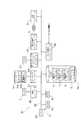
図1は、商品管理システム101を示すシステム構成図である。本実施の形態の商品管理システム101は、統括部102に設置された上位コンピュータ201と、コンビニエンスストア103に設置されて店舗業務を統括管理する店舗コンピュータ301とを有する。上位コンピュータ201と店舗コンピュータ301とは、通信ネットワーク111によって互いにデータ通信可能に接続されている。 FIG. 1 is a system configuration diagram showing a
店舗コンピュータ301には、LANケーブル131を介して複数台のPOS端末401がデータ通信可能に接続されている。POS端末401は、コンビニエンスストア103のレジ(図示せず)に配置されて、商品販売データ処理を実行する。また、コンビニエンスストア103には、統括部102に対して発注を行うための発注端末501と納入された商品を検品するための検品端末601とが備えられている。発注端末501及び検品端末601は、無線中継器121とLANケーブル131とを介して店舗コンピュータ301とデータ通信可能となっている。 A plurality of
店舗コンピュータ301は、キーボード312及びポインティングデバイスであるマウス313を備える。また、ユーザである店員に対する情報報知機能を有するユーザインターフェースとしてのLCD311を備える。 The
発注端末501は、厚みを有する平板状のハウジング501aを有する。ハウジング501aの一面側には、タッチパネル511付きのLCD512と、LCD512の側方に配置されたキーボード513とが設けられている。ハウジング501aには、肩掛け紐(図示せず)が取り付けられている。コンビニエンスストア103の店員は、この肩掛け紐を肩にかけて発注端末501を使用する。 The
検品端末601は、持ち手部分を形成するハウジング601aを有する。ハウジング601aの持ち手部分に相当する部分には、キーボード612が設けられている。ハウジング601aの先端側には、検品端末ユーザインターフェースとしてのLCD611が設けられている。また、ハウジング601aのLCD611と反対側の部分には、商品にコードシンボルの形態で付された商品コードを読み取るバーコードスキャナ614(図8参照)が設けられている。 The
図2は、上位コンピュータ201のハードウェア構成を示すブロック図である。上位コンピュータ201は、各部を駆動制御するマイクロコンピュータ251を備える。マイクロコンピュータ251は、各部を集中的に制御するCPU252に、バスライン255を介して、制御プログラム等の固定的データを予め記憶するROM253と、各種データを書き換え自在に記憶してワークエリア等として機能するRAM254とが接続されて構成されている。したがって、マイクロコンピュータ251は、情報処理を実行する第1の情報処理部を構成する。 FIG. 2 is a block diagram illustrating a hardware configuration of the
マイクロコンピュータ251には、バスライン255を介して、表示コントローラ256、キーボードコントローラ257、HDD258、及び、通信インターフェース259が接続されている。表示コントローラ256は、画像データに基づいてLCD211を駆動制御し、画像データに応じた画像をLCD211に表示させる。キーボードコントローラ257は、キーボード212からの入力信号をマイクロコンピュータ251に取り込む。通信インターフェース259は、通信ネットワーク111と接続されている。つまり、通信ネットワーク111を介して複数の店舗コンピュータ301とのデータ通信を可能とする。HDD258には、商品を特定する商品コードに対応付けて商品名、単価、分類名等を記憶する商品マスタファイルF1、店舗コンピュータ301から送信される後述する発注データに含まれる商品コード、発注数を記憶する発注マスタファイルF2、及び、後述する破損データファイルF3が格納されている。 A
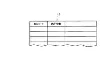
図3は、破損データファイルF3のデータ構成を示す模式図である。破損データファイルF3は、商品コードに対応付けて、商品名、分類名、破損状況を記憶するデータ構成を有する。後述するように、上位コンピュータ201のマイクロコンピュータ251は、商品コード、商品名、分類名、破損状況を含む破損データを店舗コンピュータ301から取得する。上位コンピュータ201のマイクロコンピュータ251は、取得した破損データに含まれる品コード、商品名、分類名、破損状況を破損データファイルF3に記憶させる。 FIG. 3 is a schematic diagram showing the data structure of the damaged data file F3. The damaged data file F3 has a data configuration that stores a product name, a classification name, and a damage status in association with the product code. As will be described later, the
図4は、店舗コンピュータ301のハードウェア構成を示すブロック図である。店舗コンピュータ301は、各部を駆動制御するマイクロコンピュータ351を備える。マイクロコンピュータ351は、各部を集中的に制御するCPU352に、バスライン355を介して、制御プログラム等の固定的データを予め記憶するROM353と、各種データを書き換え自在に記憶してワークエリア等として機能するRAM354とが接続されて構成されている。したがって、マイクロコンピュータ351は、情報処理を実行する第2の情報処理部を構成する。 FIG. 4 is a block diagram illustrating a hardware configuration of the
マイクロコンピュータ351には、バスライン355を介して、表示コントローラ356、キーボードコントローラ357、ポインティングデバイスコントローラ358、HDD359、第1の通信インターフェース360、及び第2の通信インターフェース361が接続されている。表示コントローラ356は、画像データに基づいてLCD311を駆動制御し、画像データに応じた画像をLCD311に表示させる。キーボードコントローラ357は、テンキー312a及び「Enter」と表示された登録キー312bを含むキーボード312からの入力信号をマイクロコンピュータ351に取り込む。ポインティングデバイスコントローラ358は、ポインティングデバイスであるマウス313からの入力信号をマイクロコンピュータ351に取り込む。第1の通信インターフェース360は、LANケーブル131を介して他の機器、つまり、POS端末401及び無線中継器121との間でのデータ通信を可能とする。第2の通信インターフェース361は、通信ネットワーク111と接続されている。つまり、通信ネットワーク111を介して上位コンピュータ201とのデータ通信を可能とする。HDD359には、商品コードに対応付けて商品名、単価、分類名等を記憶する商品データファイルF4が格納され、さらに、発注データファイルF5及び納品データファイルF6が格納されている。 A
図5は、発注データファイルF5のデータ構成を示す模式図である。発注データファイルF5は、商品コードに対応付けて発注数を記憶するデータ構成を有する。発注データファイルF5は、さらに、商品コードに対応付けて、受注先、日付等を記憶するデータ構成を有していても良い。そして、発注データファイルF5は、商品コードに対応付けて破損フラグが記憶されるデータ構成を有する。後述するように、商品コードによって特定される商品が破損し易い商品である場合には、破損フラグには、「1」が記憶される。つまり、「1」が記憶されることにより破損フラグには、壊れ易い商品である旨が記憶される。 FIG. 5 is a schematic diagram showing the data structure of the order data file F5. The order data file F5 has a data structure for storing the number of orders in association with the product code. The order data file F5 may further have a data structure for storing an order recipient, a date, etc. in association with the product code. The order data file F5 has a data structure in which a damage flag is stored in association with the product code. As will be described later, when the product specified by the product code is easily damaged, “1” is stored in the damage flag. That is, by storing “1”, the damage flag stores information indicating that the product is easily broken.
図6は、納品データファイルF6のデータ構成を示す模式図である。納品データファイルF6は、商品コードに対応付けて納品予定数を記憶するデータ構成を有する。納品データファイルF6は、さらに、商品コードに対応付けて、納品予定時等を記憶するデータ構成を有していてもよい。 FIG. 6 is a schematic diagram showing the data structure of the delivery data file F6. The delivery data file F6 has a data structure for storing the scheduled delivery number in association with the product code. The delivery data file F6 may further have a data structure for storing the scheduled delivery date in association with the product code.
図7は、発注端末501のハードウェア構成を示すブロック図である。発注端末501は、各部を駆動制御するマイクロコンピュータ551を備える。マイクロコンピュータ551は、各部を集中的に制御するCPU552に、バスライン555を介して、制御プログラム等の固定的データを予め記憶するROM553と、各種データを書き換え自在に記憶してワークエリア等として機能するRAM554とが接続されて構成されている。したがって、マイクロコンピュータ551は、情報処理を実行する情報処理部を構成する。 FIG. 7 is a block diagram illustrating a hardware configuration of the ordering
マイクロコンピュータ551には、バスライン555を介して、タッチパネルコントローラ556、表示コントローラ557、キーボードコントローラ558、無線通信インターフェース559、及び不揮発性のフラッシュメモリ562が接続されている。タッチパネルコントローラ556は、タッチパネル511からの入力信号をマイクロコンピュータ551に取り込む。表示コントローラ557は、画像データに基づいてLCD512を駆動制御し、画像データに応じた画像をLCD512に表示させる。キーボードコントローラ558は、テンキー513a及び「Enter」と表示された登録キー513bを含むキーボード513からの入力信号をマイクロコンピュータ551に取り込む。無線通信インターフェース559は、無線部560を駆動制御する。無線部560は、アンテナ561を介して無線中継器121との間で無線通信を実行する。発注端末501に入力された発注データ等の各種データは、無線部560から無線中継器121に送信される。この場合、発信されるデータは宛先を店舗コンピュータ301としている。したがって、発注端末501から発信されたデータは、店舗コンピュータ301に向けて送信される。 A
図8は、検品端末601のハードウェア構成を示すブロック図である。検品端末601は、各部を駆動制御するマイクロコンピュータ651を備える。マイクロコンピュータ651は、各部を集中的に制御するCPU652に、バスライン655を介して、制御プログラム等の固定的データを予め記憶するROM653と、各種データを書き換え自在に記憶してワークエリア等として機能するRAM654とが接続されて構成されている。したがって、マイクロコンピュータ651は、情報処理を実行する第3の情報処理部を構成する。 FIG. 8 is a block diagram illustrating a hardware configuration of the
マイクロコンピュータ651には、バスライン655を介して、表示コントローラ656、キーボードコントローラ658、スキャナコントローラ659、無線通信インターフェース660、及び不揮発性のフラッシュメモリ663が接続されている。表示コントローラ656は、画像データに基づいてLCD611を駆動制御し、画像データに応じた画像をLCD611に表示させる。キーボードコントローラ658は、キーボード612からの入力信号をマイクロコンピュータ651に取り込む。スキャナコントローラ659は、バーコードスキャナ614を駆動制御して、バーコードスキャナ614が読み取った商品コードをマイクロコンピュータ651に取り込む。無線通信インターフェース660は、無線部661を駆動制御する。無線部661は、アンテナ662を介して無線中継器121との間で無線通信を実行する。検品端末601に入力された各種データは、無線部661から無線中継器121に送信される。この場合、発信されるデータは宛先を店舗コンピュータ301としている。したがって、検品端末601から発信されたデータは、店舗コンピュータ301に向けて送信される。 A
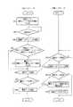
図9は、商品を発注する発注処理の流れを示すフローチャートである。商品の発注は、コンビニエンスストア103の店員が発注端末501を携帯し、商品棚(図示せず)の在庫等を確認しながら行う。まず、発注端末501のマイクロコンピュータ551は、LCD512に発注入力画面571を表示させる(ステップS101)。 FIG. 9 is a flowchart showing the flow of the ordering process for placing an order for products. Orders for merchandise are made by a store clerk at the
図10は、発注入力画面571の一例を示す模式図である。発注入力画面571は、発注商品リスト574を主体に構成されて、さらに、発注ボタン572とキャンセルボタン573とを含む。発注商品リスト574は、発注対象の商品名が表示される商品名エリア574aと、数字が入力されて発注数として表示される発注数エリア574bと、発注先名称や前回発注数等の発注参考情報が表示される発注参考情報エリア574cとから構成されている。発注端末501のマイクロコンピュータ551は、店舗コンピュータ301のHDD359に格納されている商品データファイルF4に記憶されている各商品の発注条件情報を参照して、時計部(図示せず)にて計時されている現在日時において発注が必要な商品を抽出して、その商品名と発注参考情報とを発注商品リスト574に表示する。 FIG. 10 is a schematic diagram showing an example of the
図9のフローチャートの説明に戻る。次に、発注端末501のマイクロコンピュータ551は、発注数の入力を待機する(ステップS102)。つまり、発注数エリア574bの1つがタッチ操作により選択されて、キーボード513のテンキー513aの押下操作により発注数が入力され、登録キー513bが押下されたならば(ステップS102のY)、発注端末501のマイクロコンピュータ551は、入力された発注数をRAM554に記憶させる(ステップS103)。発注数の入力は、発注ボタン572がタッチ操作されるまで(ステップS104)、行うことができる。発注ボタン572がタッチ操作されたならば(ステップS104のY)、発注端末501のマイクロコンピュータ551は、発注数が入力されてRAM554に記憶された全ての商品の商品コードとその発注数とを含む発注データを生成し、生成した発注データを店舗コンピュータ301に無線中継器121を経由して送信する(ステップS105)。店舗コンピュータ301のマイクロコンピュータ351は、発注端末501から発注データを受信したならば(ステップS106のY)、受信した発注データを、通信ネットワーク111を介して統括部102の上位コンピュータ201に送信するとともに、受信した発注データに含まれる商品コード及び発注数を発注データファイルF5に記憶させる(ステップS107)。上位コンピュータ201のマイクロコンピュータ251は、店舗コンピュータ301から受信した発注データに含まれる商品コード及び発注数を発注マスタファイルF2に記憶させる。 Returning to the flowchart of FIG. Next, the
図11は、破損商品を報告する処理の流れを示すフローチャートである。破損した商品である破損商品の報告は、コンビニエンスストア103の店員が、店舗コンピュータ301に入力して行われる。まず、キーボード312又はマウス313での所定の操作に応じて、店舗コンピュータ301のマイクロコンピュータ351は、LCD311に破損商品入力画面371を表示させる(ステップS201)。 FIG. 11 is a flowchart showing a flow of processing for reporting a damaged product. Report of a damaged product, which is a damaged product, is performed by the store clerk of the
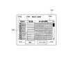
図12は、破損商品入力画面371の一例を示す模式図である。破損商品入力画面371は、商品リスト374を主体に構成されて、さらに、送信ボタン372とキャンセルボタン373とを含む。商品リスト374は、破損商品の商品コードが入力される商品コードエリア374aと、商品コードエリア374aに入力された商品コードに対応する商品名及び分類名が表示される商品名エリア374b及び分類名エリア374cと、その商品についての破損状況が入力される破損状況エリア374dとから構成されている。 FIG. 12 is a schematic diagram illustrating an example of a damaged
図11のフローチャートの説明に戻る。次に、店舗コンピュータ301のマイクロコンピュータ351は、破損商品についての商品コードの入力を待機する(ステップS202)。商品コードの入力は、例えば、キーボード312のテンキー312aによって入力される。破損商品についての商品コードが入力されてキーボード312の登録キー312bが押下されたならば(ステップS202のY)、店舗コンピュータ301のマイクロコンピュータ351は、商品データファイルF4から入力された商品コードに対応する商品名及び分類名を取得して、商品名エリア374b及び分類名エリア374cに表示させる。
そして、商品コード、商品名、分類名をRAM354に記憶させる(ステップS203)。次に、店舗コンピュータ301のマイクロコンピュータ351は、破損状況エリア374dの入力を許容する(ステップS204)。破損状況エリア374dへの入力は、キーボード312によって行われる。破損状況としては、例えば、「箱のカドがつぶれた」等の文字列が入力される。破損状況が入力されて登録キー312bが押下されたならば(ステップS204のY)、入力された破損状況をRAM354に記憶させる(ステップS205)。商品コードの入力及び破損状況の入力は、送信ボタン372がマウス313によってクリックされるまで(ステップS206)、行うことができる。送信ボタン372がクリックされたならば(ステップS206のY)、店舗コンピュータ301のマイクロコンピュータ351は、RAM354に記憶された商品コード、商品名、分類名、破損状況を含む破損データを生成し、通信ネットワーク111を介して統括部102の上位コンピュータ201に送信する(ステップS207)。上位コンピュータ201のマイクロコンピュータ251は、店舗コンピュータ301から破損データを受信したならば(ステップS208のY)、受信した破損データに含まれる商品コード、商品名、分類名、破損状況を破損データファイルF3に記憶させる(ステップS209)。つまり、ステップS209では、破損商品の商品コードを破損データファイルF3に記憶させる破損記憶処理が実行される。Returning to the flowchart of FIG. Next, the
Then, the product code, product name, and classification name are stored in the RAM 354 (step S203). Next, the
ところで、店舗コンピュータ301のマイクロコンピュータ351は、キーボード312又はマウス313での所定の操作により、破損データファイルF3の閲覧を要求する閲覧要求のデータを、通信ネットワーク111を介して上位コンピュータ201に送信する。上位コンピュータ201のマイクロコンピュータ251は、店舗コンピュータ301からの閲覧要求に応じて、破損データファイルF3の閲覧を許容する。つまり、店舗コンピュータ301のLCD311によって、上位コンピュータ201のHDD258のデータ内容が閲覧可能となる。店舗コンピュータ301のマイクロコンピュータ351は、マウス313でのクリック操作により、上位コンピュータ201のHDD258に格納されている破損データファイルF3をHDD359に格納されているアプリケーションソフトウェアASによって開く。店舗コンピュータ301のマイクロコンピュータ351は、アプリケーションソフトウェアASによって開かれた破損データファイルF3のデータ内容を閲覧画面381(図13参照)としてLCD311に表示させる。 By the way, the
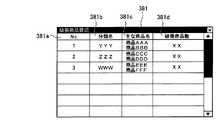
図13は、閲覧画面381の一例を示す模式図である。閲覧画面381は、破損データファイルF3のデータ内容に基づく情報を表示する。つまり、店舗コンピュータ301のマイクロコンピュータ351は、破損データファイルF3のデータ内容を分類名毎の数量をカウントして、昇順にソートして一覧表示させる。つまり、閲覧画面381は、昇順に番号を表示する昇順番号表示エリア381a、分類名を表示する分類名表示エリア381b、分類名表示エリア381bに表示された分類名の分類に含まれる主な商品名を表示する商品名表示エリア381c、及び、分類名毎の数量を表示する破損商品数表示エリア381dを含んでいる。これによれば、店舗コンピュータ301が設置されたコンビニエンスストア103の店員は、コンビニエンスストア103に居ながらにして、破損し易い商品の傾向を知ることができる。 FIG. 13 is a schematic diagram illustrating an example of the
図14は、店舗への納品前に実行される処理の流れを示すフローチャートである。まず、上位コンピュータ201のマイクロコンピュータ251は、店舗への納入が予定されている商品を特定する商品コードとその納品予定数を含む納品データを生成して、RAM254に一時記憶させる(ステップS301)。商品コード及び納品予定数は、キーボード212によってマイクロコンピュータ251に入力される。次に、上位コンピュータ201のマイクロコンピュータ251は、キーボード212等によって所定の送信指示操作がなされたならば(ステップS302のY)、HDD258に格納されている破損データファイルF3を検索し(ステップS303)、生成してRAM254に一時記憶した納品データに含まれる商品コードが破損データファイルF3に記憶されている商品コードを含むか否かを判定する(ステップS304)。含まない場合には(ステップS304のN)、通信ネットワーク111を介して納品データをコンビニエンスストア103の店舗コンピュータ301に向けて送信する(ステップS306)。一方で、含む場合には(ステップS304のY)、該当する商品コードとこの商品コードによって特定される商品が破損し易い商品である旨の警告メッセージ画面391(図15参照)のデータとを含む警告データを生成する(ステップS305)。ステップS305では、上位コンピュータ201のマイクロコンピュータ251は、該当する商品コードに対応する商品名と分類名とを商品マスタファイルF1から取得して生成する警告メッセージ画面391に表示させる。そして、納品データを店舗コンピュータ301に向けて送信し(ステップS306)、さらに、警告データを、納品データの送信先である店舗コンピュータ301に向けて送信する(ステップS307のY、ステップS308)。 FIG. 14 is a flowchart showing a flow of processing executed before delivery to the store. First, the
店舗コンピュータ301のマイクロコンピュータ351は、上位コンピュータ201から納品データを受信したならば(ステップS309のY)、受信した納品データに含まれる商品コードと納品予定数とを納品データファイルF6に記憶させる(ステップS310)。さらに、店舗コンピュータ301のマイクロコンピュータ351は、上位コンピュータ201から警告データを受信したならば(ステップS311のY)、受信した警告データに含まれる警告メッセージ画面のデータに基づいてLCD311に警告メッセージ画面391を表示させる(ステップS312)。つまり、ステップS312では、ユーザインターフェースであるLCD311に警告メッセージを報知させる警告処理が実行される。
そして、店舗コンピュータ301のマイクロコンピュータ351は、受信した警告データに含まれる商品コードと一致する商品コードに対応する発注データファイルF5の破損フラグに「1」を記憶させる(ステップS313)。このようにして、受信した警告データに含まれる商品コードによって特定される商品が壊れ易い商品である旨が、発注データファイルF5に商品コードに対応付けて記憶される。When the
Then, the
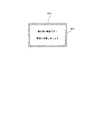
図15は、警告メッセージ画面391の一例を示す模式図である。警告メッセージ画面391は、文字列が表示されたメッセージエリア392と、「はい」と表示された了承ボタン393とを含む。メッセージエリア392には、「破損の多い商品を持つ分類が送られてきます」及び「取扱に注意しましょう」という文字列が表示されている。また、メッセージエリア392には、納入される商品であって上位コンピュータ201の破損データファイルF3に記憶されている商品の商品名及び分類名が表示されている。警告メッセージ画面391は、了承ボタン393のクリック操作に応じて店舗コンピュータ301のマイクロコンピュータ351が消去する。つまり、了承ボタン393のクリック操作があるまで警告メッセージ画面391は、LCD311に表示され続ける。 FIG. 15 is a schematic diagram illustrating an example of the
このような警告メッセージ画面391が店舗コンピュータ301のLCD311に表示されることにより、コンビニエンスストア103の店員は、破損し易い納入商品についての情報を得ることができる。こうして、納入商品の中に壊れ易い商品があることを予め知ることで商品の品出しに際してもその商品を注意して取り扱うことができる。 By displaying such a
図16は、検品処理の流れを示すフローチャートである。発注先104からコンビニエンスストア103に納品されたならば、コンビニエンスストア103の店員は、商品の検品を行う。検品は、店員が検品端末601を携帯し、納入された商品にバーコードの形態で付されている商品コードの読み取りを行うことになる。 FIG. 16 is a flowchart showing the flow of inspection processing. When the customer is delivered from the
ところで、検品端末601のマイクロコンピュータ651は、無線中継器121とLANケーブル131とを介して定期的に店舗コンピュータ301にアクセスして、店舗コンピュータ301のHDD359に格納された発注データファイルF5のデータを取得して発注データファイルF5をフラッシュメモリ663にコピーする(ステップS401)。 By the way, the
そして、検品端末601のマイクロコンピュータ651は、バーコードスキャナ614による商品コードの読み取りを待機している(ステップS402)。バーコードスキャナ614が商品コードを読み取ったならば(ステップS402のY)、発注データファイルF5を検索し、読み取った商品コードに対応する発注数を取得して、取得した発注数に基づく発注数表示(図示せず)をLCD611に表示させる(ステップS403)。そして、検品端末601のマイクロコンピュータ651は、読み取った商品コードに対応する破損フラグに「1」が記憶されているか否かを判定する(ステップS404)。破損フラグに「1」が記憶されていたならば(ステップS404のY)、検品端末601のマイクロコンピュータ651は、検品警告画面671(図17参照)を生成してLCD611に表示させる(ステップS405)。つまり、ステップS405では、読み取られた商品コードによって特定される商品が破損し易い旨をLCD611に報知させる検品警告処理が実行される。 Then, the
図17は、検品警告画面671の一例を示す模式図である。LCD611に表示された検品警告画面671は、「壊れ易い商品です! 取扱に注意しましょう」という文字列を含んでいる。このような検品警告画面671が検品端末601のLCD611に表示されることにより、検品して品出しをする店員に対しても壊れ易い商品についての取扱注意の警告をすることができる。 FIG. 17 is a schematic diagram illustrating an example of an
111…通信ネットワーク、201…上位コンピュータ(情報処理装置)、251…マイクロコンピュータ、301…店舗コンピュータ(外部情報処理装置)、311…LCD(ユーザインターフェース)、351…マイクロコンピュータ、391…警告メッセージ画面(警告メッセージ)、601…検品端末、611…LCD(表示装置)、614…バーコードスキャナ、651…マイクロコンピュータ、F3…破損データファイル、F5…発注データファイル DESCRIPTION OF
Claims (6)
Translated fromJapanese前記通信ネットワークを介して前記外部情報処理装置から、破損した商品である破損商品の商品コード及び破損状況を示したデータを含む破損データを受信する手段と、
前記受信した破損データを破損データファイルに蓄積する手段と、
店舗に対して納品すべき商品の商品コード及び納品数を含む納品データを生成する手段と、
前記生成した納品データに含まれる商品の商品コードが前記破損データファイルに含まれるか否かを判別し、含まれる場合に警告データを生成する手段と、
を備えた情報処理装置。Means for receiving the product code of the ordered product and the number of orders from the external information processing apparatus via the communication network;
Means for receiving, from the external information processing apparatus via the communication network, damaged data including data indicating a product code and a damage status of a damaged product which is a damaged product;
Means for storing the received corrupted data in a corrupted data file;
Means for generating delivery data including the product code of the product to be delivered to the store and the number of deliveries;
Means for determining whether or not a product code of a product included in the generated delivery data is included in the damaged data file, and generating warning data if included;
An information processing apparatus comprising:
前記警告データを受信すると、前記発注に対応する発注データファイルの破損警告フラグを設定する外部情報処理装置。An external information processing apparatus capable of communicating with the information processing apparatus according to claim 1 via the communication network,
An external information processing apparatus that sets a damage warning flag of an order data file corresponding to the order when the warning data is received.
請求項2記載の外部情報処理装置。A warning screen is displayed based on the warning data, and the warning screen continues to be displayed until an approval operation is performed.
The external information processing apparatus according to claim 2.
商品コードを読み取り可能なスキャナと、
各種情報を表示する表示装置と、を備え、
前記スキャナにより読み取った商品コードに対応する破損警告フラグが設定されている場合に、前記表示装置に警告画面を表示する、
外部情報処理装置。An external information processing apparatus capable of communicating with the information processing apparatus according to claim 1 via a communication network,
A scanner that can read the product code;
A display device for displaying various information,
When a damage warning flag corresponding to the product code read by the scanner is set, a warning screen is displayed on the display device.
External information processing device.
破損した商品である破損商品の商品コード及び破損状況を示したデータを含む破損データを受信する過程と、
前記受信した破損データを破損データファイルに蓄積する過程と、
店舗に対して納品すべき商品の商品コード及び納品数を含む納品データを生成する過程と、
前記生成した納品データに含まれる商品の商品コードが前記破損データファイルに含まれるか否かを判別し、含まれる場合に警告データを生成する過程と、
前記警告データに基づいて表示された警告画面について、了承操作がなされるまで表示を継続する過程と、
を備えた情報処理方法。Receiving the product code of the ordered product and the number of orders;
Receiving damaged data including the product code of the damaged product, which is a damaged product, and data indicating the damage status;
Storing the received corrupted data in a corrupted data file;
A process of generating delivery data including a product code and a delivery number of a product to be delivered to the store;
Determining whether or not a product code of a product included in the generated delivery data is included in the damaged data file, and generating warning data if included;
The process of continuing to display the warning screen displayed based on the warning data until an approval operation is performed,
An information processing method comprising:
前記コンピュータを、
発注された商品の商品コード及び発注数を通信ネットワークを介して外部情報処理装置から受信する手段と、
前記通信ネットワークを介して前記外部情報処理装置から、破損した商品である破損商品の商品コード及び破損状況を示したデータを含む破損データを受信する手段と、
前記受信した破損データを破損データファイルに蓄積する手段と、
店舗に対して納品すべき商品の商品コード及び納品数を含む納品データを生成する手段と、
前記生成した納品データに含まれる商品の商品コードが前記破損データファイルに含まれるか否かを判別し、含まれる場合に警告データを生成する手段と、
して機能させる制御プログラム。A control program for controlling an information processing apparatus capable of communicating with an external information processing apparatus via a communication network by a computer,
The computer,
Means for receiving the product code of the ordered product and the number of orders from the external information processing apparatus via the communication network;
Means for receiving, from the external information processing apparatus via the communication network, damaged data including data indicating a product code and a damage status of a damaged product which is a damaged product;
Means for storing the received corrupted data in a corrupted data file;
Means for generating delivery data including the product code of the product to be delivered to the store and the number of deliveries;
Means for determining whether or not a product code of a product included in the generated delivery data is included in the damaged data file, and generating warning data if included;
Control program to function.
Priority Applications (1)
| Application Number | Priority Date | Filing Date | Title |
|---|---|---|---|
| JP2011045568AJP5139548B2 (en) | 2011-03-02 | 2011-03-02 | Host computer, store computer, information processing method and control program |
Applications Claiming Priority (1)
| Application Number | Priority Date | Filing Date | Title |
|---|---|---|---|
| JP2011045568AJP5139548B2 (en) | 2011-03-02 | 2011-03-02 | Host computer, store computer, information processing method and control program |
Related Parent Applications (1)
| Application Number | Title | Priority Date | Filing Date |
|---|---|---|---|
| JP2007178538ADivisionJP4700032B2 (en) | 2007-07-06 | 2007-07-06 | Product management system |
Publications (2)
| Publication Number | Publication Date |
|---|---|
| JP2011108283Atrue JP2011108283A (en) | 2011-06-02 |
| JP5139548B2 JP5139548B2 (en) | 2013-02-06 |
Family
ID=44231587
Family Applications (1)
| Application Number | Title | Priority Date | Filing Date |
|---|---|---|---|
| JP2011045568AExpired - Fee RelatedJP5139548B2 (en) | 2011-03-02 | 2011-03-02 | Host computer, store computer, information processing method and control program |
Country Status (1)
| Country | Link |
|---|---|
| JP (1) | JP5139548B2 (en) |
Cited By (1)
| Publication number | Priority date | Publication date | Assignee | Title |
|---|---|---|---|---|
| JP2017146988A (en)* | 2017-04-25 | 2017-08-24 | 東芝テック株式会社 | Information processing apparatus and program |
Citations (4)
| Publication number | Priority date | Publication date | Assignee | Title |
|---|---|---|---|---|
| JPH11296581A (en)* | 1998-04-08 | 1999-10-29 | Hitachi Ltd | Cargo information management method and cargo management system using electronic tags |
| JP2002123762A (en)* | 2000-10-16 | 2002-04-26 | Sanyo Electric Logistics Co Ltd | Method for delivering commodity for mass sales store |
| JP2004302795A (en)* | 2003-03-31 | 2004-10-28 | Seiko Epson Corp | Business time management system, business time management device, business time management method, and program |
| JP2009015699A (en)* | 2007-07-06 | 2009-01-22 | Toshiba Tec Corp | Product management device |
- 2011
- 2011-03-02JPJP2011045568Apatent/JP5139548B2/ennot_activeExpired - Fee Related
Patent Citations (4)
| Publication number | Priority date | Publication date | Assignee | Title |
|---|---|---|---|---|
| JPH11296581A (en)* | 1998-04-08 | 1999-10-29 | Hitachi Ltd | Cargo information management method and cargo management system using electronic tags |
| JP2002123762A (en)* | 2000-10-16 | 2002-04-26 | Sanyo Electric Logistics Co Ltd | Method for delivering commodity for mass sales store |
| JP2004302795A (en)* | 2003-03-31 | 2004-10-28 | Seiko Epson Corp | Business time management system, business time management device, business time management method, and program |
| JP2009015699A (en)* | 2007-07-06 | 2009-01-22 | Toshiba Tec Corp | Product management device |
Cited By (1)
| Publication number | Priority date | Publication date | Assignee | Title |
|---|---|---|---|---|
| JP2017146988A (en)* | 2017-04-25 | 2017-08-24 | 東芝テック株式会社 | Information processing apparatus and program |
Also Published As
| Publication number | Publication date |
|---|---|
| JP5139548B2 (en) | 2013-02-06 |
Similar Documents
| Publication | Publication Date | Title |
|---|---|---|
| JP2023068022A (en) | Information processor, information processing method, and program | |
| JP2004265196A (en) | Method for coordinating electronic bin tag to article, electronic bin tag system and information acquiring system | |
| CN105405225B (en) | Printing control device and printing control method | |
| CN106558158B (en) | Work management device and work management method | |
| JP5623600B1 (en) | Expiration date management device and expiration date management program | |
| JP5139548B2 (en) | Host computer, store computer, information processing method and control program | |
| JP4961608B2 (en) | Warranty system | |
| JP4700032B2 (en) | Product management system | |
| JP2006285971A (en) | Self-order system, order input terminal, and order processing method | |
| JP2006178718A (en) | Information processing apparatus with work instruction function and program | |
| JP7035326B2 (en) | Server equipment, asset management systems, control methods, and programs | |
| JP5450539B2 (en) | Mobile terminal and program | |
| JP6470021B2 (en) | Input support apparatus and program | |
| US9361644B2 (en) | Systems, methods, and apparatus for wireless thermal printing for order fulfillment | |
| JP6953901B2 (en) | Sales data processing equipment, communication systems, communication methods, and programs | |
| JP2009203024A (en) | Picking system | |
| CN106548312B (en) | Terminal device, management device, and management system | |
| JP7294473B2 (en) | SERVER DEVICE, ASSET MANAGEMENT SYSTEM, CONTROL METHOD, AND PROGRAM | |
| JP7713409B2 (en) | Ordering device, ordering system, and program | |
| JP6265707B2 (en) | Server and program | |
| CN106406773B (en) | Job management device, job management system, and job management method | |
| JP6673380B2 (en) | Work management device and program | |
| JP2016033747A (en) | Information processing device for it environment-independent inspection, inspection method and inspection program in information processing device | |
| JP5654919B2 (en) | Label master management server and label master management program | |
| JP2007052605A (en) | Price presenting apparatus and price presenting program |
Legal Events
| Date | Code | Title | Description |
|---|---|---|---|
| A621 | Written request for application examination | Free format text:JAPANESE INTERMEDIATE CODE: A621 Effective date:20110302 | |
| A977 | Report on retrieval | Free format text:JAPANESE INTERMEDIATE CODE: A971007 Effective date:20120813 | |
| A131 | Notification of reasons for refusal | Free format text:JAPANESE INTERMEDIATE CODE: A131 Effective date:20120821 | |
| A521 | Request for written amendment filed | Free format text:JAPANESE INTERMEDIATE CODE: A523 Effective date:20121018 | |
| TRDD | Decision of grant or rejection written | ||
| A01 | Written decision to grant a patent or to grant a registration (utility model) | Free format text:JAPANESE INTERMEDIATE CODE: A01 Effective date:20121113 | |
| A01 | Written decision to grant a patent or to grant a registration (utility model) | Free format text:JAPANESE INTERMEDIATE CODE: A01 | |
| A61 | First payment of annual fees (during grant procedure) | Free format text:JAPANESE INTERMEDIATE CODE: A61 Effective date:20121115 | |
| R150 | Certificate of patent or registration of utility model | Free format text:JAPANESE INTERMEDIATE CODE: R150 | |
| FPAY | Renewal fee payment (event date is renewal date of database) | Free format text:PAYMENT UNTIL: 20151122 Year of fee payment:3 | |
| LAPS | Cancellation because of no payment of annual fees |