JP2011103552A - Information processor, and signal processing method - Google Patents
Information processor, and signal processing methodDownload PDFInfo
- Publication number
- JP2011103552A JP2011103552AJP2009257350AJP2009257350AJP2011103552AJP 2011103552 AJP2011103552 AJP 2011103552AJP 2009257350 AJP2009257350 AJP 2009257350AJP 2009257350 AJP2009257350 AJP 2009257350AJP 2011103552 AJP2011103552 AJP 2011103552A
- Authority
- JP
- Japan
- Prior art keywords
- signal
- symbol
- unit
- value
- amplitude
- Prior art date
- Legal status (The legal status is an assumption and is not a legal conclusion. Google has not performed a legal analysis and makes no representation as to the accuracy of the status listed.)
- Withdrawn
Links
- 238000003672processing methodMethods0.000titleclaimsabstractdescription8
- 230000005540biological transmissionEffects0.000claimsabstractdescription182
- 230000001934delayEffects0.000claimsabstractdescription5
- 230000001360synchronised effectEffects0.000claimsabstractdescription3
- 238000000034methodMethods0.000claimsdescription183
- 238000001514detection methodMethods0.000claimsdescription35
- 230000007274generation of a signal involved in cell-cell signalingEffects0.000claimsdescription32
- 230000010365information processingEffects0.000claimsdescription27
- 230000008054signal transmissionEffects0.000claimsdescription24
- 238000012545processingMethods0.000claimsdescription18
- 230000003111delayed effectEffects0.000claimsdescription16
- 230000008859changeEffects0.000claimsdescription9
- 230000008569processEffects0.000claimsdescription6
- 238000006243chemical reactionMethods0.000description62
- 238000001228spectrumMethods0.000description25
- 239000004973liquid crystal related substanceSubstances0.000description11
- 238000011084recoveryMethods0.000description11
- 238000010586diagramMethods0.000description10
- 230000004048modificationEffects0.000description6
- 238000012986modificationMethods0.000description6
- 230000015572biosynthetic processEffects0.000description5
- 238000003786synthesis reactionMethods0.000description5
- 230000014509gene expressionEffects0.000description4
- 230000004044responseEffects0.000description4
- 230000006866deteriorationEffects0.000description3
- 239000000284extractSubstances0.000description2
- 230000009467reductionEffects0.000description2
- 230000008901benefitEffects0.000description1
- 238000004891communicationMethods0.000description1
- 238000013461designMethods0.000description1
- 230000000694effectsEffects0.000description1
- 238000005516engineering processMethods0.000description1
- 230000008520organizationEffects0.000description1
- 230000001172regenerating effectEffects0.000description1
- 230000000630rising effectEffects0.000description1
- 230000003595spectral effectEffects0.000description1
Images


Classifications
- H—ELECTRICITY
- H03—ELECTRONIC CIRCUITRY
- H03M—CODING; DECODING; CODE CONVERSION IN GENERAL
- H03M5/00—Conversion of the form of the representation of individual digits
- H03M5/02—Conversion to or from representation by pulses
- H03M5/04—Conversion to or from representation by pulses the pulses having two levels
- H03M5/14—Code representation, e.g. transition, for a given bit cell depending on the information in one or more adjacent bit cells, e.g. delay modulation code, double density code
- H03M5/145—Conversion to or from block codes or representations thereof
- H—ELECTRICITY
- H03—ELECTRONIC CIRCUITRY
- H03M—CODING; DECODING; CODE CONVERSION IN GENERAL
- H03M5/00—Conversion of the form of the representation of individual digits
- H03M5/02—Conversion to or from representation by pulses
- H03M5/20—Conversion to or from representation by pulses the pulses having more than three levels
Landscapes
- Engineering & Computer Science (AREA)
- Theoretical Computer Science (AREA)
- Dc Digital Transmission (AREA)
Abstract
Description
Translated fromJapanese本発明は、情報処理装置、及び信号処理方法に関する。 The present invention relates to an information processing apparatus and a signal processing method.
携帯電話やノート型のパーソナルコンピュータ(以下、ノートPC)等の情報処理装置は、ユーザが操作する本体部分と、情報が表示される表示部分とを接続するヒンジ部分に可動部材が用いられていることが多い。ところが、ヒンジ部分には多数の信号線や電力線が配線されており、配線の信頼性を維持する工夫が求められる。まず、考えられるのが、ヒンジ部分を通る信号線の数を減らすことである。そこで、本体部分と表示部分との間においては、パラレル伝送方式ではなく、シリアル伝送方式でデータの伝送処理が行われるようにする。このようにシリアル伝送方式を用いると信号線の本数が低減される。 In an information processing apparatus such as a mobile phone or a notebook personal computer (hereinafter referred to as a notebook PC), a movable member is used at a hinge portion that connects a main body portion operated by a user and a display portion on which information is displayed. There are many cases. However, since many signal lines and power lines are wired in the hinge portion, a device for maintaining the reliability of the wiring is required. First, it is conceivable to reduce the number of signal lines passing through the hinge portion. Therefore, data transmission processing is performed between the main body portion and the display portion not by the parallel transmission method but by the serial transmission method. When the serial transmission method is used in this way, the number of signal lines is reduced.
さて、シリアル伝送方式の場合、データは符号化されてから伝送される。その際、符号化方式としては、例えば、NRZ(Non Return to Zero)符号方式やマンチェスター符号方式、或いは、AMI(Alternate Mark Inversion)符号方式等が用いられる。例えば、下記の特許文献1には、バイポーラ符号の代表例であるAMI符号を利用してデータ伝送する技術が開示されている。また、同文献には、データクロックを信号レベルの中間値で表現して伝送し、受信側で信号レベルに基づいてデータクロックを再生する技術が開示されている。 In the case of a serial transmission method, data is encoded and then transmitted. In this case, for example, an NRZ (Non Return to Zero) code system, a Manchester code system, an AMI (Alternate Mark Inversion) code system, or the like is used as the encoding system. For example,
しかしながら、ノートPCのような情報処理装置においては、上記の符号を用いるシリアル伝送方式を用いても、依然としてヒンジ部分に配線される信号線の本数が多い。例えば、ノートPCの場合、表示部分に伝送されるビデオ信号の他、LCDを照明するためのLEDバックライトに関する配線が存在し、これらの信号線を含めると数十本程度の信号線がヒンジ部に配線されることになる。但し、LCDは、Liquid Crystal Displayの略である。また、LEDは、Light Emitting Diodeの略である。 However, in an information processing apparatus such as a notebook PC, even if the serial transmission method using the above-described code is used, the number of signal lines wired to the hinge portion is still large. For example, in the case of a notebook PC, there is a wiring related to an LED backlight for illuminating the LCD in addition to a video signal transmitted to the display portion. When these signal lines are included, about several tens of signal lines are connected to the hinge portion. Will be wired. However, LCD is an abbreviation for Liquid Crystal Display. LED is an abbreviation for Light Emitting Diode.
上記のような理由から、直流成分を含まず、かつ、受信信号からクロック成分を容易に抽出することが可能な符号化方式(以下、新方式)が開発された。この新方式に基づいて生成された伝送信号は直流成分を含まないため、直流電源に重畳して伝送することができる。さらに、この伝送信号から極性反転周期を検出することにより、受信側でPLLを用いずにクロックを再生することが可能になる。そのため、複数の信号線を纏めることが可能になり、信号線の本数を減らすことができると共に、消費電力及び回路規模の低減が実現される。但し、PLLは、Phase Locked Loopの略である。 For the above reasons, an encoding method (hereinafter referred to as a new method) has been developed that does not include a DC component and that can easily extract a clock component from a received signal. Since the transmission signal generated based on this new system does not contain a DC component, it can be transmitted superimposed on a DC power source. Furthermore, by detecting the polarity inversion period from this transmission signal, it is possible to reproduce the clock without using a PLL on the receiving side. Therefore, a plurality of signal lines can be collected, the number of signal lines can be reduced, and power consumption and circuit scale can be reduced. However, PLL is an abbreviation for Phase Locked Loop.
さて、最近では、アプリケーションの多様化に伴い、LCDの解像度が大きく向上している。そのため、上記のような消費電力の低減と共に、伝送速度の高速化が1つの大きな課題となっている。伝送速度の高速化は、単純にクロックを高速化することにより実現できる。しかし、シリアル伝送路においてクロックを高速化すると、伝送信号の周波数スペクトラムが広帯域化して携帯電話等に対する電磁妨害(EMI)が発生してしまう。また、クロックの高速化は消費電力の増加をもたらす。但し、EMIは、Electro Magnetic Interferenceの略である。 Now, with the diversification of applications, the resolution of LCDs has greatly improved. Therefore, along with the reduction in power consumption as described above, increasing the transmission speed is one major issue. The transmission speed can be increased by simply increasing the clock speed. However, when the clock speed is increased in the serial transmission path, the frequency spectrum of the transmission signal becomes wider, and electromagnetic interference (EMI) occurs with respect to a mobile phone or the like. In addition, an increase in clock speed leads to an increase in power consumption. However, EMI is an abbreviation for Electro Magnetic Interface.
そこで、より多くのデータを、クロック周波数を上げることなく伝送することが可能な符号化方法が求められている。また、上記のように直流電源に伝送信号を重畳して伝送する場合、DC遮断特性を持つ伝送路を通じて信号が伝送されるため、伝送信号のDCバランスを良好な状態に調整することが可能な符号化方法が望ましい。こうした理由から、本発明は、上記問題に鑑みてなされたものであり、本発明の目的とするところは、データ伝送に利用する帯域を低く抑えつつ、データの伝送速度を高速化することが可能な、新規かつ改良された情報処理装置、及び信号処理方法を提供することを目的とする。 Thus, there is a need for an encoding method that can transmit more data without increasing the clock frequency. In addition, when transmitting a transmission signal superimposed on a DC power source as described above, the signal is transmitted through a transmission path having a DC cutoff characteristic, so that the DC balance of the transmission signal can be adjusted to a good state. An encoding method is desirable. For these reasons, the present invention has been made in view of the above problems, and an object of the present invention is to increase the data transmission speed while keeping the bandwidth used for data transmission low. Another object of the present invention is to provide a new and improved information processing apparatus and signal processing method.
上記課題を解決するために、本発明のある観点によれば、入力データをMビット単位で分配してMビットのビット列をN組生成する分配器と、前記分配器により分配されたN組のビット列をそれぞれKシンボルの2値シンボル列に変換してN組の2値シンボル列を生成する符号化部と、所定のシンボルクロックに同期し、かつ、前記N組の2値シンボル列に含まれる各シンボル値を振幅値とするN個の送信信号Sj(j=1〜N)を生成する信号生成部と、j=1〜Nの各々に関し、前記信号生成部により生成された送信信号Sjを(j−1)/Nシンボル時間だけ遅延させて遅延信号Rjを生成する信号遅延部と、前記信号遅延部により生成された遅延信号Rj(j=1〜N)を加算して加算信号を生成する信号加算部と、前記信号加算部により生成された加算信号を送信する信号送信部と、を備える、情報処理装置が提供される。 In order to solve the above problems, according to an aspect of the present invention, a distributor that distributes input data in units of M bits to generate N sets of M-bit bit strings, and N sets of N sets that are distributed by the distributor. An encoding unit that converts each bit string into a binary symbol string of K symbols to generate N sets of binary symbol strings, and is included in the N sets of binary symbol strings in synchronization with a predetermined symbol clock. A signal generation unit that generates N transmission signals Sj (j = 1 to N) having each symbol value as an amplitude value, and for each of j = 1 to N, the transmission signal Sj generated by the signal generation unit A signal delay unit that generates a delay signal Rj with a delay of (j-1) / N symbol time and a delay signal Rj (j = 1 to N) generated by the signal delay unit are added to generate an addition signal Signal adding unit and the signal adding unit And a signal transmission unit that transmits more generated sum signal, the information processing apparatus is provided.
また、上記の情報処理装置は、前記信号送信部により送信された加算信号を受信する信号受信部と、前記加算信号の振幅値を1/Nシンボル時間単位で順次検出する振幅検出部と、前記振幅検出部により検出された前記加算信号の振幅値に基づいて前記N組の2値シンボル列に含まれる各シンボル値を算出するシンボル値算出部と、前記シンボル値算出部により算出された各シンボル値を含む前記N組の2値シンボル列をそれぞれ前記Mビットのビット列に変換して前記N組のビット列を復号する復号部と、前記復号部により復号されたN組のビット列を結合して前記入力データを復元するデータ復元部と、をさらに備えていてもよい。 The information processing apparatus includes a signal receiving unit that receives the addition signal transmitted by the signal transmission unit, an amplitude detection unit that sequentially detects the amplitude value of the addition signal in units of 1 / N symbol time, A symbol value calculation unit that calculates each symbol value included in the N sets of binary symbol sequences based on the amplitude value of the addition signal detected by the amplitude detection unit, and each symbol calculated by the symbol value calculation unit A decoding unit that converts the N sets of binary symbol sequences including values into the M-bit bit sequence and decodes the N sets of bit sequences, and combines the N sets of bit sequences decoded by the decoding unit, And a data restoring unit that restores the input data.
また、前記2値シンボル列の先頭に位置するシンボル値は、前記N組の2値シンボル列のいずれも同じ所定値に設定されており、前記シンボル値算出部は、前記振幅検出部により検出された前記加算信号の振幅値の変化を検出し、変化がある場合には同じ2値シンボル列に含まれる前のシンボル値を反転したシンボル値を現シンボル値に設定し、変化がない場合には同じ2値シンボル列に含まれる前のシンボル値と同じシンボル値を現シンボル値に設定する処理を順次繰り返すことにより、前記N組の2値シンボル列に含まれる各シンボル値を算出するように構成されていてもよい。 The symbol value located at the head of the binary symbol sequence is set to the same predetermined value in all of the N sets of binary symbol sequences, and the symbol value calculation unit is detected by the amplitude detection unit. The change of the amplitude value of the added signal is detected, and if there is a change, the symbol value obtained by inverting the previous symbol value included in the same binary symbol string is set as the current symbol value. Each symbol value included in the N sets of binary symbol sequences is calculated by sequentially repeating the process of setting the same symbol value as the previous symbol value included in the same binary symbol sequence as the current symbol value. May be.
また、前記符号化部は、前記Mビットのビット列を直流成分が抑圧された前記Kシンボルの2値シンボル列に変換するように構成されていてもよい。 The encoding unit may be configured to convert the M-bit bit string into a binary symbol string of the K symbols in which a DC component is suppressed.
また、前記2値シンボル列の先頭に位置するシンボル値は、前記N組の2値シンボル列のいずれも同じ所定値に設定されており、前記信号送信部は、前記加算信号の前段に同期信号を付加して送信し、前記シンボル値算出部は、前記同期信号の後段で、前記振幅検出部により1番目に検出された振幅値X(1)に基づいて前記送信信号S1の1番目のシンボル時間における振幅値A(1,1)を算出し、前記振幅検出部によりL番目(2≦L≦N)に検出された振幅値X(L)、前記振幅値A(p,1)(p=1〜L−1)に基づいて前記送信信号SLの1番目のシンボル時間における振幅値A((p+1),1)を算出し、前記振幅検出部によりQ*N+1番目(1≦Q≦K−1)に検出された振幅値X(Q*N+1)、前記振幅値A(p,q)(p=1〜N、q=1〜Q)に基づいて前記送信信号S1の(Q+1)番目のシンボル時間における振幅値A(1,(Q+1))を算出し、前記振幅検出部によりQ*N+L’番目(2≦L’≦N)に検出された振幅値X(Q*N+L’)、前記振幅値A(p,q)(p=1〜N、q=1〜Q)、A(p’,(Q+1))(p’=1〜L’−1)に基づいて前記送信信号SL’の(Q+1)番目のシンボル時間における振幅値A(L’,(Q+1))を算出するように構成されていてもよい。 Further, the symbol value located at the head of the binary symbol sequence is set to the same predetermined value in all of the N sets of binary symbol sequences, and the signal transmission unit is configured to generate a synchronization signal before the addition signal. And the symbol value calculation unit transmits the first symbol of the transmission signal S1 based on the amplitude value X (1) detected first by the amplitude detection unit after the synchronization signal. An amplitude value A (1,1) in time is calculated, and the amplitude value X (L) detected by the amplitude detection unit Lth (2 ≦ L ≦ N), the amplitude value A (p, 1) (p = 1 to L−1), the amplitude value A ((p + 1), 1) in the first symbol time of the transmission signal SL is calculated, and the amplitude detection unit performs Q * N + 1th (1 ≦ Q ≦ K). -1) detected amplitude value X (Q * N + 1), the amplitude value A (p q) Based on (p = 1 to N, q = 1 to Q), the amplitude value A (1, (Q + 1)) in the (Q + 1) -th symbol time of the transmission signal S1 is calculated, and the amplitude detector Q * N + L ′ (2 ≦ L ′ ≦ N) detected amplitude value X (Q * N + L ′), the amplitude value A (p, q) (p = 1 to N, q = 1 to Q), Based on A (p ′, (Q + 1)) (p ′ = 1 to L′−1), the amplitude value A (L ′, (Q + 1)) in the (Q + 1) -th symbol time of the transmission signal SL ′ is calculated. It may be configured to.
また、上記の情報処理装置は、映像データを出力する演算処理部と、前記映像データを表示する表示部と、をさらに備えていてもよく、前記入力データは、前記演算処理部により出力された映像データであり、前記表示部は、前記データ復元部により復元された映像データを表示するように構成されていてもよい。 The information processing apparatus may further include an arithmetic processing unit that outputs video data and a display unit that displays the video data, and the input data is output by the arithmetic processing unit. It is video data, and the display unit may be configured to display the video data restored by the data restoration unit.
また、上記課題を解決するために、本発明の別の観点によれば、入力データをMビット単位で分配してMビットのビット列をN組生成する分配ステップと、前記分配ステップで分配されたN組のビット列をそれぞれKシンボルの2値シンボル列に変換してN組の2値シンボル列を生成する符号化ステップと、所定のシンボルクロックに同期し、かつ、前記N組の2値シンボル列に含まれる各シンボル値を振幅値とするN個の送信信号Sj(j=1〜N)を生成する信号生成ステップと、j=1〜Nの各々に関し、前記信号生成ステップで生成された送信信号Sjを(j−1)/Nシンボル時間だけ遅延させて遅延信号Rjを生成する信号遅延ステップと、前記信号遅延ステップで生成された遅延信号Rj(j=1〜N)を加算して加算信号を生成する信号加算ステップと、を含む、信号処理方法が提供される。 In order to solve the above problem, according to another aspect of the present invention, a distribution step of distributing input data in M-bit units to generate N sets of M-bit bit strings, and the distribution step distributes the input data. An encoding step for converting N sets of bit sequences into binary symbols of K symbols to generate N sets of binary symbols, and N sets of binary symbols in synchronization with a predetermined symbol clock. A signal generation step for generating N transmission signals Sj (j = 1 to N) having amplitude values as symbol values included in the transmission, and the transmission generated in the signal generation step for each of j = 1 to N A signal delay step for delaying the signal Sj by (j−1) / N symbol time to generate a delay signal Rj and the delay signal Rj (j = 1 to N) generated in the signal delay step are added and added. Signal Comprising a signal summing step of forming, a signal processing method is provided.
また、上記課題を解決するために、本発明の別の観点によれば、入力データをMビット単位で分配してMビットのビット列を2組生成する分配器と、前記分配器により分配された2組のビット列をそれぞれKシンボルの2値シンボル列に変換して第1及び第2の2値シンボル列を生成する符号化部と、前記第1の2値シンボル列に含まれる各シンボル値を振幅値とする第1の送信信号と、前記第2の2値シンボル列に含まれる各シンボル値を振幅値とする第2の送信信号と、を生成する信号生成部と、前記信号生成部により生成された第1の送信信号が有する振幅値を1/K(Kは自然数)に調整する振幅調整部と、前記振幅調整部により振幅値が調整された第1の送信信号と、前記信号生成部により生成された第2の送信信号と、を同期加算して加算信号を生成する信号加算部と、前記信号加算部により生成された加算信号を送信する信号送信部と、を備える、情報処理装置が提供される。 In order to solve the above problem, according to another aspect of the present invention, a distributor that distributes input data in units of M bits to generate two sets of M-bit bit strings and the distributor distributes the data. An encoding unit for converting the two sets of bit sequences into binary symbol sequences of K symbols to generate first and second binary symbol sequences, and symbol values included in the first binary symbol sequence, A signal generation unit that generates a first transmission signal having an amplitude value and a second transmission signal having each symbol value included in the second binary symbol string as an amplitude value; and An amplitude adjustment unit that adjusts an amplitude value of the generated first transmission signal to 1 / K (K is a natural number), a first transmission signal whose amplitude value is adjusted by the amplitude adjustment unit, and the signal generation And the second transmission signal generated by the unit A signal adder for generating a sum signal and, and a signal transmitting unit for transmitting the added signal generated by the signal adding unit, the information processing apparatus is provided.
また、上記の情報処理装置は、前記信号送信部により送信された加算信号を受信する信号受信部と、前記振幅調整部により調整された第1の送信信号の振幅値がA又はーAであり、前記第2の送信信号の振幅値がB又は−B(A=B/K)である場合に、第1の振幅値(B+A)、第2の振幅値(B−A)、第3の振幅値(−B+A)、及び第4の振幅値(−B−A)を判別するための複数の閾値を用いて、前記信号受信部により受信された加算信号の振幅値を判別する振幅判別部と、前記振幅判別部による判別結果に基づいて前記第1及び第2の送信信号の振幅値を検出し、前記第1及び第2の2値シンボル列を復元するシンボル列復元部と、前記シンボル列復元部により復元された第1及び第2の2値シンボル列を前記2組のビット列に変換する復号部と、前記復号部により変換された2組のビット列を結合して前記入力データを復元するデータ復元部と、をさらに備えていてもよい。 In the above information processing apparatus, the amplitude value of the signal transmission unit that receives the addition signal transmitted from the signal transmission unit and the first transmission signal adjusted by the amplitude adjustment unit is A or −A. , When the amplitude value of the second transmission signal is B or −B (A = B / K), the first amplitude value (B + A), the second amplitude value (B−A), the third An amplitude discriminating unit that discriminates the amplitude value of the added signal received by the signal receiving unit using a plurality of threshold values for discriminating the amplitude value (−B + A) and the fourth amplitude value (−B−A). A symbol sequence restoring unit that detects amplitude values of the first and second transmission signals based on a discrimination result by the amplitude discriminating unit and restores the first and second binary symbol sequences; and the symbol The first and second binary symbol sequences restored by the sequence restoration unit are converted into the two sets of bit sequences. A decoding unit for conversion, and a data recovery unit for combining the two sets of bit string converted by the decoder to restore the input data may further include a.
また、前記符号化部は、前記Mビットのビット列を直流成分が抑圧された前記Kシンボルの2値シンボル列に変換するように構成されていてもよい。 The encoding unit may be configured to convert the M-bit bit string into a binary symbol string of the K symbols in which a DC component is suppressed.
また、上記の情報処理装置は、映像データを出力する演算処理部と、前記映像データを表示する表示部と、をさらに備えていてもよく、前記入力データは、前記演算処理部により出力された映像データであり、前記表示部は、前記データ復元部により復元された映像データを表示するように構成されていてもよい。 The information processing apparatus may further include an arithmetic processing unit that outputs video data and a display unit that displays the video data, and the input data is output by the arithmetic processing unit. It is video data, and the display unit may be configured to display the video data restored by the data restoration unit.
また、上記課題を解決するために、本発明の別の観点によれば、入力データをMビット単位で分配してMビットのビット列を2組生成する分配ステップと、前記分配ステップで分配された2組のビット列をそれぞれKシンボルの2値シンボル列に変換して第1及び第2の2値シンボル列を生成する符号化ステップと、前記第1の2値シンボル列に含まれる各シンボル値を振幅値とする第1の送信信号と、前記第2の2値シンボル列に含まれる各シンボル値を振幅値とする第2の送信信号と、を生成する信号生成ステップと、前記信号生成ステップで生成された第1の送信信号が有する振幅値を1/K(Kは自然数)に調整する振幅調整ステップと、前記振幅調整ステップで振幅値が調整された第1の送信信号と、前記信号生成ステップで生成された第2の送信信号と、を同期加算して加算信号を生成する信号加算ステップと、を含む、信号処理方法が提供される。 In order to solve the above-described problem, according to another aspect of the present invention, a distribution step of distributing input data in units of M bits to generate two sets of M-bit bit strings, and the distribution step distributes the input data. An encoding step of converting the two sets of bit sequences into binary symbol sequences of K symbols to generate first and second binary symbol sequences, and symbol values included in the first binary symbol sequence A signal generation step of generating a first transmission signal having an amplitude value and a second transmission signal having an amplitude value of each symbol value included in the second binary symbol sequence; and An amplitude adjustment step for adjusting the amplitude value of the generated first transmission signal to 1 / K (K is a natural number), a first transmission signal whose amplitude value is adjusted in the amplitude adjustment step, and the signal generation Generate by step The includes a second transmission signal, and the signal adding step of generating a sum signal by adding synchronization and a signal processing method is provided.
以上説明したように本発明によれば、データ伝送に利用する帯域を低く抑えつつ、データの伝送速度を高速化することが可能になる。 As described above, according to the present invention, it is possible to increase the data transmission speed while keeping the bandwidth used for data transmission low.
以下に添付図面を参照しながら、本発明の好適な実施の形態について詳細に説明する。なお、本明細書及び図面において、実質的に同一の機能構成を有する構成要素については、同一の符号を付することにより重複説明を省略する。 Exemplary embodiments of the present invention will be described below in detail with reference to the accompanying drawings. In addition, in this specification and drawing, about the component which has the substantially same function structure, duplication description is abbreviate | omitted by attaching | subjecting the same code | symbol.
[説明の流れについて]
ここで、以下に記載する本発明の実施形態に関する説明の流れについて簡単に述べる。まず、図1を参照しながら、シリアル伝送方式を採用した携帯端末10の装置構成について説明する。次いで、図2を参照しながら、AMI符号の信号波形及びその特性について説明する。次いで、図3を参照しながら、新方式に係る携帯端末10の機能構成について説明する。次いで、図4、図5を参照しながら、新方式に係る符号化方法、及び当該符号化方法により得られる伝送信号の周波数スペクトラムについて説明する。次いで、図6〜図7Cを参照しながら、8B6T変換方式に基づく符号化方法について説明する。[About the flow of explanation]
Here, the flow of explanation regarding the embodiment of the present invention described below will be briefly described. First, the device configuration of the
次いで、図8〜図11Bを参照しながら、本発明の第1実施形態に係る符号化方法、及びその符号化方法を実現することが可能な送信側の構成について説明する。次いで、図9、図12、図13を参照しながら、同実施形態に係る復号方法、及びその復号方法を実現することが可能な受信側の構成について説明する。次いで、図14〜図16Bを参照しながら、本発明の第2実施形態に係る符号化方法、及びその符号化方法を実現することが可能な送信側の構成について説明する。次いで、図17〜図19を参照しながら、同実施形態に係る復号方法、及びその復号方法を実現することが可能な受信側の構成について説明する。 Next, the encoding method according to the first embodiment of the present invention and the configuration on the transmission side capable of realizing the encoding method will be described with reference to FIGS. 8 to 11B. Next, the decoding method according to the embodiment and the configuration on the receiving side capable of realizing the decoding method will be described with reference to FIGS. 9, 12, and 13. Next, an encoding method according to the second embodiment of the present invention and a configuration on the transmission side capable of realizing the encoding method will be described with reference to FIGS. 14 to 16B. Next, the decoding method according to the embodiment and the configuration on the receiving side capable of realizing the decoding method will be described with reference to FIGS.
次いで、図20、図21を参照しながら、本発明の第1及び第2実施形態に係る符号化方法のポイントについて纏める。最後に、表現を整理して同実施形態の技術的思想について纏め、当該技術的思想から得られる作用効果について簡単に説明する。 Next, the points of the encoding method according to the first and second embodiments of the present invention will be summarized with reference to FIGS. Finally, the expressions are organized and the technical ideas of the embodiment are summarized, and the effects obtained from the technical ideas are briefly described.
(説明項目)
1:はじめに
1−1:シリアル伝送方式について
1−2:新方式(多値伝送方式)について
1−3:8B6T変換方式について
2:第1実施形態
2−1:符号化方法
2−2:復号方法
3:第2実施形態
3−1:符号化方法
3−2:復号方法
3−3:変形例
4:まとめ
4−1:ポイントの整理
4−2:表現の整理(Description item)
1: Introduction 1-1: Serial transmission system 1-2: New system (multi-value transmission system) 1-3: 8B6T conversion system 2: First embodiment 2-1: Coding method 2-2: Decoding Method 3: Second Embodiment 3-1: Coding Method 3-2: Decoding Method 3-3: Modified Example 4: Summary 4-1: Arrangement of Points 4-2: Arrangement of Expressions
<1:はじめに>
以下で本発明の一実施形態に係る技術について詳細な説明を行うが、これに先立ち、本実施形態の技術を適用可能なシリアル伝送方式、及び上記の新方式について説明する。<1: Introduction>
Hereinafter, a technique according to an embodiment of the present invention will be described in detail. Prior to this, a serial transmission scheme to which the technique of the present embodiment can be applied and the above-described new scheme will be described.
[1−1:シリアル伝送方式について]
まず、図1を参照しながら、シリアル伝送方式を採用した携帯端末10の装置構成について簡単に説明する。図1は、シリアル伝送方式を採用した携帯端末10の装置構成の一例を示す説明図である。[1-1: Serial transmission method]
First, the device configuration of the
図1には、携帯端末10の一例として携帯電話が模式的に描画されている。しかし、以下で説明する技術の適用範囲は携帯電話に限定されない。例えば、ノートPC等の情報処理装置や各種の携帯型電子機器にも適用可能である。また、以下の説明においては、一例として画像データが伝送されるケースについて述べるが、伝送される信号の種類はこれに限定されない。例えば、制御データや音声データ等の信号が伝送されてもよい。 In FIG. 1, a mobile phone is schematically drawn as an example of the
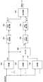
図1に示すように、携帯端末10は、主に、操作部12と、ヒンジ部14と、表示部16と、を有する。操作部12は、ベースバンドプロセッサ22(BBP)と、パラレル信号ライン24と、シリアライザ26とを有する。ヒンジ部14には、シリアル信号ライン28が配線されている。また、表示部16は、主に、デシリアライザ30と、パラレル信号ライン32と、液晶部34(LCD)と、を有する。但し、LCDは、Liquid Crystal Displayの略である。 As shown in FIG. 1, the
液晶部34は、表示部16に設けられている。液晶部34は、画像データを表示する表示手段の一例である。ここでは一例としてLCDを示したが、表示部16に設けられる表示手段の種類はこれに限定されない。例えば、表示部16に設けられる表示手段は、OELD(Organic Electro−Luminescent Display)やPDP(Plasma Display Panel)等であってもよい。 The
また、ヒンジ部14は、表示部16と操作部12とを接続する部材(以下、接続部材)により形成される。この接続部材は、例えば、表示部16をZ−Y平面内で180度回転できるようにしたり、或いは、X−Z平面内で表示部16を回転できるようにしたりする可動構造を有している。また、この接続部材は、自由な方向に表示部16を配置できるような可動構造を有していてもよい。 Further, the
また、ベースバンドプロセッサ22は、携帯端末10の通信制御やアプリケーションの実行機能を提供する演算処理部の一例である。ベースバンドプロセッサ22は、制御データや画像データ等をパラレル信号の形で出力する。例えば、画像データのパラレル信号は、表示部16に伝送され、液晶部34における画面表示に用いられる。このようなパラレル信号をそのまま伝送するには、多数の信号線が必要になる。例えば、一般的な携帯電話の画面表示に用いられるパラレル信号線の本数は約50本である。 The
そのため、パラレル伝送方式を採用する一般的な折り畳み式携帯電話の場合、ヒンジ部分に約50本のパラレル信号線が配線されている。そのため、ヒンジ部分の可動範囲は、多くの場合、一方向に限られている。仮に、図1に示した携帯端末10のように、Z−Y平面内で180度回転できるようにすると、ヒンジ部分に配線された約50本のパラレル信号線に捻れや引っ張りの力が加わり、その力が強いとパラレル信号線が断線してしまう。そのため、パラレル伝送方式を採用する一般的な折り畳み式携帯電話の場合、ヒンジ部分の可動範囲が限られていた。 Therefore, in the case of a general foldable mobile phone adopting a parallel transmission system, about 50 parallel signal lines are wired in the hinge portion. Therefore, the movable range of the hinge portion is often limited to one direction. If the
しかし、デザイン性やユーザの利便性を向上させるために、断線の危険を回避しつつ、ヒンジ部分の可動範囲を広げる工夫が求められている。こうした要求を受けて、図1に示すようなシリアル伝送方式の携帯端末10が考案されたのである。携帯端末10は、操作部12から表示部16に信号を伝送する際、パラレル信号を一旦シリアル信号に変換してから伝送する。そのため、携帯端末10のヒンジ部14に配線される信号線の本数は、パラレル伝送方式を採用する一般的な携帯電話に比べて格段に少ない。以下、携帯端末10の構成について、より詳細に説明する。 However, in order to improve the design and the convenience of the user, there is a demand for a device that expands the movable range of the hinge part while avoiding the risk of disconnection. In response to such a request, a serial transmission type
携帯端末10は、ヒンジ部14に配線されたシリアル信号ライン28を通じ、シリアル伝送方式に基づいて画像データ等のデータを伝送する。そのため、操作部12には、シリアライザ26が設けられている。シリアライザ26は、ベースバンドプロセッサ22から出力されたパラレル信号をシリアル化するものである。一方、表示部16には、デシリアライザ30が設けられている。デシリアライザ30は、シリアル信号ライン28を通じて伝送されるシリアル信号をパラレル化するものである。 The
ベースバンドプロセッサ22から出力されたパラレル信号は、パラレル信号ライン24を介してシリアライザ26に入力される。パラレル信号が入力されると、シリアライザ26は、入力されたパラレル信号をシリアル化してシリアル信号を生成する。シリアライザ26により生成されたシリアル信号は、シリアル信号ライン28を通じてデシリアライザ30に入力される。シリアル信号が入力されると、デシリアライザ30は、入力されたシリアル信号をパラレル化してパラレル信号を生成する。デシリアライザ30により生成されたパラレル信号は、パラレル信号ライン32を通じて液晶部34に入力される。 The parallel signal output from the
上記の通り、シリアル信号ライン28は、データ信号の伝送に利用される。但し、シリアル信号ライン28は、データ信号とクロックとを共に伝送するために利用されてもよい。シリアル信号ライン28の配線数kは、一般的な携帯電話のヒンジ部分に配線されるパラレル信号ラインの配線数nよりも大幅に少ない(1≦k≪n)。また、シリアル信号ライン28の配線数kは、電源ラインにデータ信号及びクロックを重畳して伝送する方式(例えば、上記の新方式等)を利用した場合、1程度にまで低減される。 As described above, the
このように、シリアル伝送方式を採用すると、一般的な携帯電話で用いられるパラレル伝送方式を採用した場合に比べ、ヒンジ部14に配線される信号線の数を大幅に低減させることができる。ヒンジ部14に配線される信号線の本数が減ることにより、信号線の信頼性を維持しつつ、ヒンジ部14の可動範囲を大きくすることができる。例えば、信号線の本数を1本程度に減らすと、ヒンジ部14の変形に伴う信号線のねじれや引っ張り等が生じ難くなるため、信号線が断線する危険性は大幅に低くなる。 As described above, when the serial transmission method is employed, the number of signal lines wired to the
以上、携帯端末10の装置構成について簡単に説明した。シリアル伝送方式を採用した携帯端末10の装置構成は概ね上記の通りである。上記のように、シリアル伝送方式を採用することにより、ヒンジ部14に配線される信号線の本数を減らすことができる。但し、信号線の本数は、シリアル信号ライン28に流れる信号の特性や伝送方法に依存する。例えば、直流成分を含まないデータ信号を電源ラインに重畳して伝送する伝送方式の場合、データラインと電源ラインとを1〜2本程度に纏めることができるようになる。 The apparatus configuration of the
ところで、多くの場合、シリアル信号ライン28に流れるデータ信号は符号化されている。つまり、データを送信する際、携帯端末10は、データを符号化して符号化データに変換し、符号化データに基づいて生成されたデータ信号をシリアル信号ライン28で伝送する。また、携帯端末10は、シリアル信号ライン28で伝送されたデータ信号の振幅値をコンパレータを用いて検出し、符号化データを復元する。さらに、携帯端末10は、符号化データを復号して元のデータを復元する。 By the way, in many cases, the data signal flowing in the
符号化データの復号処理は、符号化データの生成時に用いたクロックが利用される。このクロックは、通常、PLLを用いてデータ信号から再生される。しかし、最近、PLLを用いずにデータ信号からクロックを再生することが可能な符号化方法(新方式)が考案された。この符号化方法を用いると、データ信号の受信側(例えば、表示部16)にPLLを設けずに済むようになり、消費電力を低減することができる。また、PLLを設けない分だけ回路規模を縮小することができる。携帯端末10のような小型の電子機器においては、省電力化が強く求められており、新方式の符号化方法を用いることが望まれる。 The decoding process of the encoded data uses the clock used when generating the encoded data. This clock is usually recovered from the data signal using a PLL. Recently, however, an encoding method (new method) has been devised that can recover a clock from a data signal without using a PLL. When this encoding method is used, it is not necessary to provide a PLL on the data signal receiving side (for example, the display unit 16), and power consumption can be reduced. Further, the circuit scale can be reduced by the amount that the PLL is not provided. In a small electronic device such as the
[1−2:新方式(多値伝送方式)について]
ここで、図2〜図4を参照しながら、新方式の符号化方法について簡単に説明する。なお、以下では、AMI符号をベースとする新方式の符号化方法に関して具体的な説明を試みるが、新方式の符号化方法に適用可能な符号の種類はAMI符号に限定されない。例えば、パーシャル・レスポンス符号、マンチェスター符号、CMI符号、その他のバイポーラ符号やバイフェーズ符号等も適用対象に含まれる。[1-2: New method (multilevel transmission method)]
Here, a new encoding method will be briefly described with reference to FIGS. In the following, a specific description will be made regarding the new encoding method based on the AMI code, but the type of code applicable to the new encoding method is not limited to the AMI code. For example, partial response codes, Manchester codes, CMI codes, other bipolar codes, biphase codes, and the like are also included in the application target.
(AMI符号の信号波形について)
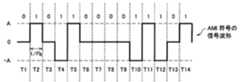
まず、AMI符号について簡単に説明する。図2を参照しながら、AMI符号の信号波形、及びAMI符号の特性について簡単に説明する。図2は、AMI符号の信号波形の一例を示す説明図である。AMI符号は、データ0を電位0で表現し、データ1を電位A又は−A(Aは任意の正数)で表現することで得られる。但し、電位Aと電位−Aとは交互に繰り返される。つまり、電位Aでデータ1が表現された後、再びデータ1が現れた場合、そのデータ1は電位−Aで表現される。このように極性反転を繰り返してデータが表現されるため、AMI符号は、ほとんど直流成分を含まない符号となる。(Signal waveform of AMI code)
First, the AMI code will be briefly described. The signal waveform of the AMI code and the characteristics of the AMI code will be briefly described with reference to FIG. FIG. 2 is an explanatory diagram illustrating an example of a signal waveform of the AMI code. The AMI code is obtained by expressing
AMI符号と同様の特性を持つ符号としては、例えば、PR(1,−1)、PR(1,0,−1)、PR(1,0,…,−1)等で表現されるパーシャル・レスポンス符号が挙げられる。このように極性反転を利用してデータを表現する伝送符号のことをバイポーラ符号と呼ぶ。なお、後述する新方式の符号化方法には、ダイコード符号やバイフェーズ符号等を利用することも可能である。但し、以下の説明においては、デューティ100%のAMI符号をベースとする符号化方法について述べる。 As a code having the same characteristics as the AMI code, for example, a partial code represented by PR (1, -1), PR (1, 0, -1), PR (1, 0, ..., -1), etc. A response code is mentioned. A transmission code that expresses data using polarity inversion in this way is called a bipolar code. In addition, a dicode code, a biphase code, etc. can also be utilized for the encoding method of the new system mentioned later. However, in the following description, an encoding method based on an AMI code with a duty of 100% will be described.
図2には、期間T1〜T14のAMI符号が模式的に記載されている。図中において、データ1は、タイミングT2、T4、T5、T10、T11、T12、T14に現れている。タイミングT2において電位Aである場合、タイミングT4では電位−Aとなる。また、タイミングT5では電位Aとなる。このように、データ1に対応する振幅は、プラスとマイナスとが交互に反転する。なお、プラス・マイナスが交互に反転する特性を極性反転と呼ぶことにする。一方、データ0に関しては全て電位0で表現される。 FIG. 2 schematically shows the AMI codes in the periods T1 to T14. In the figure,
こうした表現によりAMI符号は直流成分をほとんど含まない符号となる。但し、タイミングT6、…、T9に見られるようにデータの組み合わせによっては電位0が連続する区間が現れてしまう。このように電位0が連続すると、PLLを用いずに信号波形からクロック成分を取り出すことが難しくなる。つまり、受信側にPLLを設けることが必要になる。このような問題に鑑み、AMI符号(又は同等の特性を有する符号)にクロックを重畳して伝送する方法(新方式の符号化方法)が考案された。 With such an expression, the AMI code becomes a code that hardly contains a DC component. However, as seen at timings T6,..., T9, depending on the combination of data, a section where the
(携帯端末10の機能構成)
以下、図3を参照しながら、新方式に係る携帯端末10の機能構成について説明する。図3は、新方式に係る携帯端末10の機能構成の一例を示す説明図である。但し、図3は、シリアライザ26、及びデシリアライザ30の機能構成を中心に描画した説明図であり、他の構成要素に関する記載を省略している。(Functional configuration of mobile terminal 10)
Hereinafter, the functional configuration of the
(シリアライザ26)
まず、シリアライザ26について説明する。図3に示すように、シリアライザ26は、P/S変換部102と、エンコーダ104と、ドライバ106と、PLL部108と、タイミング制御部110と、により構成される。(Serializer 26)
First, the
図3に示すように、シリアライザ26には、ベースバンドプロセッサ22から、パラレル信号(P−DATA)と、パラレル信号用クロック(P−CLK)とが入力される。シリアライザ26に入力されたパラレル信号は、P/S変換部102によりシリアル信号に変換される。P/S変換部102により変換されたシリアル信号は、エンコーダ104に入力される。エンコーダ104は、シリアル信号にヘッダ等を付加して送信フレームを生成する。さらに、エンコーダ104は、生成した送信フレームを後述する新方式の符号化方法により符号化して伝送信号を生成する。 As shown in FIG. 3, the parallel signal (P-DATA) and the parallel signal clock (P-CLK) are input to the
ここで、図4を参照しながら、エンコーダ104における符号化信号の生成方法について説明する。図4は、新方式に係る符号化方法の一例を示す説明図である。なお、図4には、AMI符号をベースとする符号化方法が記載されている。しかし、新方式の符号化方法に用いることが可能な符号の種類はこれに限定されず、AMI符号と同等の特性を有する他の符号を同様に用いることができる。例えば、新方式の符号化方法は、バイポーラ符号やパーシャル・レスポンス符号等に応用することもできる。 Here, a method of generating an encoded signal in the
図4(C)の符号波形は、新方式の符号化方法により生成されたものである。この符号波形は、データ1を複数の電位A1(−1、−3、1、3)で表現し、データ0を電位A1とは異なる複数の電位A2(−2、2)で表現することにより得られたものである。この符号波形の特徴は、クロックの半周期毎に極性反転する点、及び連続して同じ電位とならない点にある。例えば、タイミングT6、…、T9においてデータ0が続く区間を参照すると、電位が−2、2、−2、2となっている。そのため、同じデータ値が連続して現れても、振幅の立ち上がり、立ち下がりの両エッジを検出することにより、PLLを用いずにクロック成分を検出することが可能になる。 The code waveform in FIG. 4C is generated by a new encoding method. In this code waveform,
このような符号波形は、例えば、図4(A)に示すようなAMI符号の符号波形に、図4(B)に示すようなクロックを同期加算する方法により得られる。この方法を実現するため、エンコーダ104は加算器ADDを備えている。まず、エンコーダ104は、入力されたシリアル信号をAMI符号に符号化し、図4(A)に示すようなAMI符号の符号波形を生成する。次いで、エンコーダ104は、生成したAMI符号の符号波形を加算器ADDに入力する。さらに、エンコーダ104は、図4(B)に示すようなクロックを発生させて加算器ADDに入力する。 Such a code waveform is obtained, for example, by a method of synchronously adding a clock as shown in FIG. 4B to a code waveform of an AMI code as shown in FIG. In order to implement this method, the
但し、クロックは、図4(B)に示すように、AMI符号の伝送速度Fbの半分の周波数(Fb/2)を有する。さらに、このクロックは、AMI符号の振幅に比べてN倍(N>1;図4の例ではN=2)の大きさの振幅を有する。このように、AMI符号と、そのAMI符号が持つ振幅よりも大きな振幅を有するクロックとを加算することにより、図4(C)に示すように、クロックの半周期毎に振幅がゼロクロスする符号波形が得られる。このとき、AMI符号の符号波形とクロックとはエッジを揃えて同期加算される。このようにしてエンコーダ104により新方式の符号波形(伝送信号)が生成される。 However, the clock has a frequency (Fb / 2) that is half the transmission rate Fb of the AMI code, as shown in FIG. Further, this clock has an amplitude that is N times (N> 1; N = 2 in the example of FIG. 4) as compared with the amplitude of the AMI code. In this way, by adding the AMI code and a clock having an amplitude larger than that of the AMI code, as shown in FIG. 4C, a code waveform in which the amplitude crosses zero every half cycle of the clock. Is obtained. At this time, the code waveform of the AMI code and the clock are synchronously added with the edges aligned. In this way, the
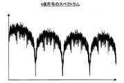
なお、新方式の符号波形は1つのデータに対して複数の振幅レベルを有する。例えば、図4(C)に例示した新方式の符号波形は、振幅レベルとして3、2、1、−1、−2、−3の6値を取り得るものである。そのうち、2、−2はデータ0に対応し、3、1、−1、−3はデータ1に対応する。つまり、新方式の符号は多値符号(図4の例では6値符号)である。また、新方式の符号波形が持つ周波数スペクトラムは、図5に示すような形状になる。上記の通り、新方式の符号にはクロック成分が含まれているため、周波数スペクトラムにも、クロック周波数Fb/2の位置に線スペクトルが現れている。 The code waveform of the new method has a plurality of amplitude levels for one data. For example, the code waveform of the new method illustrated in FIG. 4C can take six values of 3, 2, 1, -1, -2, and -3 as amplitude levels. Among them, 2 and -2 correspond to
以上、エンコーダ104による符号化方法、及びエンコーダ104により生成される符号波形の特徴について説明した。なお、ここでは説明を簡単にするためにAMI符号とクロックとを同期加算して新方式の符号波形を生成する方法について述べたが、所定の符号則に基づいてデータを新方式の符号波形に直接エンコードする方法もある。例えば、図4の例では、所定の符号則に基づいてデータ列0、1、0、1、1、0、…、1から振幅レベル2、−1、2、−3、3、−2、…、−1を決定することで、その決定結果に基づいて新方式の符号波形が生成される。 The encoding method by the
再び図3を参照する。上記のようにしてエンコーダ104により符号化されたシリアル信号は、ドライバ106に入力される。ドライバ106は、入力されたシリアル信号をLVDSによる差動伝送方式でデシリアライザ30に伝送する。一方、シリアライザ26に入力されたパラレル信号用クロックは、PLL部108に入力される。 Refer to FIG. 3 again. The serial signal encoded by the
PLL部108は、パラレル信号用クロックからシリアル信号用クロックを生成し、P/S変換部102、及びタイミング制御部110に入力する。タイミング制御部110は、入力されるシリアル信号用クロックに基づいてエンコーダ104によるシリアル信号の送信タイミングを制御する。このようにしてシリアライザ26からデシリアライザ30にシリアル信号が伝送される。 The
(デシリアライザ30)
次に、デシリアライザ30について説明する。図3に示すように、デシリアライザ30は、主に、レシーバ112と、デコーダ114と、S/P変換部116と、タイミング制御部120と、クロック検出部118と、により構成される。なお、クロック検出部118は、PLLを持たない。(Deserializer 30)
Next, the
さて、デシリアライザ30には、LVDSによる差動伝送方式でシリアライザ26からシリアル信号が伝送される。このシリアル信号は、レシーバ112により受信される。レシーバ112により受信されたシリアル信号は、デコーダ114、及びクロック検出部118に入力される。デコーダ114は、入力されたシリアル信号のヘッダを参照してデータの先頭部分を検出し、エンコーダ104により符号化されたシリアル信号を復号する。 Now, a serial signal is transmitted from the
ここで、再び図4を参照しながら、デコーダ114による復号方法について説明する。上記の通り、シリアル信号は、エンコーダ104により6値の振幅レベルを持つ符号波形に符号化されている。そこで、デコーダ114は、複数の閾値レベルを基準にして閾値判定を行い、各振幅レベルをコンパレートする。そして、デコーダ114は、閾値判定により得られた各振幅レベルを元のデータに変換することで、エンコーダ104により符号化されたシリアル信号を復号する。 Here, the decoding method by the
例えば、図4(C)に示す4つの閾値(L1、L2、L3、L4)を用いることにより、データ1に対応する振幅レベルA1(−1、−3、1、3)と、データ0に対応する振幅レベルA2(−2、2)とが判別される。まず、デコーダ114は、入力された信号の振幅レベルと上記の4つの閾値レベルとを比較し、振幅レベルがA1であるか、A2であるかを判定する。次いで、デコーダ114は、振幅レベルがA1と判定されたタイミングでデータ1を出力し、振幅レベルがA2と判定されたタイミングでデータ0を出力することにより、エンコーダ104により符号化されたシリアル信号を復号する。 For example, by using the four threshold values (L1, L2, L3, L4) shown in FIG. 4C, the amplitude level A1 (-1, -3, 1, 3) corresponding to the
再び図3を参照する。このようにしてデコーダ114により復元されたシリアル信号はS/P変換部116に入力される。S/P変換部116は、入力されたシリアル信号をパラレル信号(P−DATA)に変換する。S/P変換部116で変換されたパラレル信号は、液晶部34に入力される。パラレル信号が映像信号である場合、液晶部34により映像信号に基づいて映像が表示される。 Refer to FIG. 3 again. The serial signal restored by the
さて、上記の復号処理を実行するにはクロックが必要になる。このクロックは、クロック検出部118により供給される。クロック検出部118は、レシーバ112により受信した信号からクロック成分を検出する。そして、クロック検出部118は、検出したクロック成分を用いて元のクロックを再生する。先に述べた通り、新方式の符号波形は、AMI符号にクロックを同期加算して得られるものである。そして、この符号波形は、クロックの半周期毎に極性が反転する。そのため、クロック成分は、受信信号の振幅レベルがゼロクロスするタイミングを検出することで得られる。つまり、クロック検出部118は、PLLを用いずにクロックを再生することができる。そして、PLLを設けずに済む分だけ、デシリアライザ30の消費電力及び回路規模を低減させることが可能になる。 Now, a clock is required to execute the above decoding process. This clock is supplied by the
クロック検出部118は、受信信号から検出したクロック成分を用いて元のクロックを再生する。そして、クロック検出部118により再生されたクロックは、デコーダ114、及びタイミング制御部120に入力される。デコーダ114に入力されたクロックは、デコーダ114における復号処理に用いられる。また、タイミング制御部120は、クロック検出部118から入力されたクロックに基づいて受信タイミングを制御する。また、タイミング制御部120に入力されたクロックは、パラレル信号用クロック(P−CLK)に変換され、液晶部104に向けて出力される。 The
なお、デコーダ114、及びクロック検出部118で実施される閾値判定処理は、各閾値に対応するコンパレータを用いて実行される。例えば、クロック検出部118は、閾値L0を持つコンパレータの出力結果に基づいてクロック成分を抽出する。また、デコーダ114は、6値の振幅レベル3、2、1、−1、−2、−3を判定するために、4つの閾値L1(2.5)、L2(1.5)、L3(−1.5)、L4(−2.5)を持つコンパレータを利用する。そして、これらコンパレータの出力結果に基づいて振幅レベルが判定される。さらに、その判定結果に基づいて元のNRZデータが復元される。 Note that threshold determination processing performed by the
このように、直流成分を含まず、極性反転周期からクロック成分を検出することが可能な新方式の符号を利用することで、デシリアライザ30にて実行されるクロックの検出にPLLを用いずに済み、携帯端末10の消費電力が大きく低減する。なお、上記の例ではLVDSによる差動伝送方式が例示されていたが、直流電源から供給される電力信号に新方式の符号波形を重畳して伝送することも可能である。このような構成にすることで、ヒンジ部14の可動範囲をさらに拡大することが可能になる。 In this way, by using a new code that does not include a DC component and can detect a clock component from the polarity inversion period, it is not necessary to use a PLL for clock detection executed by the
(課題の整理)
上記の通り、新方式の符号化方法により生成される伝送信号は多値信号である。また、AMI符号に符号化する際に2値のデータ(NRZデータ)を3値のデータに変換しているため、1つのビット値を複数の振幅レベルで表現することになり、冗長度が増えてしまっている。このような形で冗長度が増えても伝送速度は増加しない。そこで、本件発明者は、多値信号の冗長度を生かし、より伝送速度を向上させる方法を考案した。(Organization of issues)
As described above, the transmission signal generated by the new encoding method is a multilevel signal. In addition, since binary data (NRZ data) is converted into ternary data when encoded into an AMI code, one bit value is expressed by a plurality of amplitude levels, increasing redundancy. It has been. Even if the redundancy increases in this way, the transmission rate does not increase. Therefore, the present inventor has devised a method for further improving the transmission speed by taking advantage of the redundancy of the multilevel signal.
[1−3:8B6T変換方式について]
多値信号を利用して伝送速度を向上させる方法としては、例えば、IEEE802.3uにおいて規定されている8B6T変換方式が知られている。8B6T変換方式は、8ビットのデータを3値の6シンボルで表現し、8ビットのデータを6シンボル期間で伝送するものである。従って、8B6T変換方式を用いると、クロック周波数を増加させずに伝送速度を4/3=1.33倍に向上させることができる。8B6T変換方式の符号化に用いる8B6T変換(入力データ→送信符号)は、図6に示すように、8B6T変換テーブル130を用いて実現される。[1-3: 8B6T conversion method]
As a method for improving the transmission speed using a multilevel signal, for example, an 8B6T conversion method defined in IEEE 802.3u is known. In the 8B6T conversion method, 8-bit data is represented by ternary 6 symbols, and 8-bit data is transmitted in 6 symbol periods. Therefore, when the 8B6T conversion method is used, the transmission rate can be improved to 4/3 = 1.33 times without increasing the clock frequency. The 8B6T conversion (input data → transmission code) used for the encoding of the 8B6T conversion method is realized using an 8B6T conversion table 130 as shown in FIG.
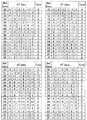
まず、図7A〜図7Dを参照しながら、IEEE802.3uにおいて規定されている8B6T変換について説明する。Ethernet(登録商標)の規格の中に100BASE−T4というカテゴリが存在し、IEEE802.3uとして標準化されている。IEEE802.3uにおいて仕様が規定されている符号は8B6T(以下、8B6T符号)と呼ばれるものである。8B6T符号は、IEEE802.3uにて規定された変換テーブル(図7A〜図7Dを参照)に基づいて8ビットの2値データを3値の6シンボルに変換することにより得られる。 First, the 8B6T conversion defined in IEEE802.3u will be described with reference to FIGS. 7A to 7D. There is a category of 100BASE-T4 in the Ethernet (registered trademark) standard, which is standardized as IEEE 802.3u. A code whose specification is defined in IEEE802.3u is called 8B6T (hereinafter, 8B6T code). The 8B6T code is obtained by converting 8-bit binary data into ternary 6 symbols based on a conversion table defined in IEEE 802.3u (see FIGS. 7A to 7D).
例えば、8ビットの2進データ10001110(8Eh)は、この変換テーブルを用いると、0,+1,0,−1,0,0に変換される。この場合、6シンボルのDCバランス(=0+1+0−1+0+0)は0となる。同様に、2進データ01011100(5Ch)は、この変換テーブルを用いると、+1,+1,0,−1,−1,+1に変換される。この場合、6シンボルのDCバランス(=1+1+0−1−1+1)は+1となる。この変換テーブルの中にはDCバランスが0となる組み合わせが134個存在し、残り122個の組み合わせは全てDCバランスが+1となる。 For example, 8-bit binary data 100001110 (8Eh) is converted into 0, +1, 0, -1, 0, 0 using this conversion table. In this case, the DC balance of 6 symbols (= 0 + 1 + 0-1 + 0 + 0) is 0. Similarly, binary data 01011100 (5Ch) is converted into +1, +1, 0, -1, -1, +1 using this conversion table. In this case, the DC balance of 6 symbols (= 1 + 1 + 0-1-1 + 1) is +1. In this conversion table, there are 134 combinations with a DC balance of 0, and the remaining 122 combinations all have a DC balance of +1.
そのため、8B6T変換テーブルを使用すると、符号化すべきデータ列に含まれる2進データのパターンによっては、DCバランスが+1の組み合わせが続いてしまい、8B6T符号列のDCバランスが正の方向に大きく崩れてしまう。このようなDCバランスの崩れが生じると、低域遮断の伝送路において著しい波形の劣化が生じてしまう。その結果、受信側で各振幅レベルを判定する際に判定誤りが増加し、伝送品質が大きく低下してしまう。また、図7A〜図7Dに示すように、8B6T変換テーブルに含まれる8Bデータ列と6Tシンボル列との組み合わせ数は非常に多い。そのため、このような8B6T変換テーブルを機器内に保持させると、その回路規模が非常に大きくなってしまう。 Therefore, when the 8B6T conversion table is used, depending on the binary data pattern included in the data sequence to be encoded, a combination of DC balance of +1 is continued, and the DC balance of the 8B6T code sequence is greatly collapsed in the positive direction. End up. When such a DC balance collapse occurs, a significant waveform deterioration occurs in the low-frequency cutoff transmission path. As a result, determination errors increase when determining each amplitude level on the receiving side, and transmission quality is greatly reduced. As shown in FIGS. 7A to 7D, the number of combinations of 8B data strings and 6T symbol strings included in the 8B6T conversion table is very large. Therefore, if such an 8B6T conversion table is held in the device, the circuit scale becomes very large.
上記のような問題点を解決するために、本件発明者は、サイズの小さな変換テーブルを用いて、クロックを高速化せずに伝送速度が向上し、かつ、DCバランスの良好な多値信号を生成することが可能な符号化方法を考案した。以下、この符号化方法に係る第1及び第2実施形態について順次説明する。 In order to solve the above-described problems, the present inventor uses a conversion table with a small size to improve the transmission speed without increasing the clock speed and to generate a multi-value signal with a good DC balance. An encoding method that can be generated has been devised. Hereinafter, the first and second embodiments according to the encoding method will be sequentially described.
<2:第1実施形態>
以下、本発明の第1実施形態について説明する。本実施形態の技術は、例えば、上記の携帯端末10におけるシリアル信号ライン28を通じたデータ伝送に適用可能である。<2: First Embodiment>
The first embodiment of the present invention will be described below. The technique of the present embodiment is applicable to data transmission through the
先に述べた通り、伝送速度を向上させるためには単純にクロックを高速化すればよい。しかし、クロックが高速化すると、シリアル信号線路を流れる伝送信号の周波数スペクトルが広帯域化し、EMIによる影響が増加してしまう。そこで、本実施形態においては、サイズの小さな変換テーブルを利用して、伝送信号の周波数スペクトルを広帯域化させずに伝送速度を向上させることが可能な符号化方法を提案する。また、DC遮断特性の伝送路における信号伝送が想定されているため、本実施形態の技術は、さらに、このような伝送路において伝送品質の劣化を招かず、かつ、周波数スペクトルの広帯域化を回避しつつ、伝送速度を向上させることを目的とする。 As described above, in order to improve the transmission speed, the clock may be simply increased. However, when the clock speed increases, the frequency spectrum of the transmission signal flowing through the serial signal line becomes wider and the influence of EMI increases. Therefore, in the present embodiment, an encoding method is proposed that can improve the transmission rate without using a small-size conversion table without widening the frequency spectrum of the transmission signal. In addition, since signal transmission is assumed in the transmission path with DC cutoff characteristics, the technique of the present embodiment further prevents deterioration of transmission quality in such a transmission path and avoids widening of the frequency spectrum. However, it aims at improving the transmission rate.
[2−1:符号化方法]
まず、本実施形態に係る符号化方法について説明する。本実施形態に係る符号化方法は、入力されたビット列をN系統(N≧2)に分配して符号化するものである。また、本実施形態に係る符号化方法は、各系統のシンボル列に含まれるシンボル値を系統毎に調整する処理ステップを含む。この処理ステップによりシンボル値が調整された各系統のシンボル列に基づいて各系統の伝送信号が生成されると、N系統の伝送信号が加算され、例えば、シリアル信号ライン28を通じて伝送される。なお、系統毎にシンボル値が調整されているため、N系統の伝送信号を加算したとしても、各系統のシンボル列を容易に復元することができる。このように、N系統を加算して伝送することにより、1シンボル期間に伝送されるシンボル数をN倍にすることができる。以下、具体例を挙げて説明する。[2-1: Encoding method]
First, the encoding method according to the present embodiment will be described. In the encoding method according to the present embodiment, an input bit string is distributed and encoded into N systems (N ≧ 2). In addition, the encoding method according to the present embodiment includes a processing step of adjusting the symbol value included in the symbol string of each system for each system. When the transmission signal of each system is generated based on the symbol string of each system whose symbol value is adjusted by this processing step, the N system transmission signals are added and transmitted through, for example, the
(送信側の構成)
ここで、図8を参照しながら、本実施形態に係る符号化方法、及び信号伝送方法を実現することが可能な送信側の構成について、具体例を挙げて説明する。図8は、本実施形態に係る符号化方法、及び信号伝送方法を実現することが可能な送信側の構成例を示す説明図である。例えば、この構成は、携帯端末10のシリアライザ26に適用可能である。(Sender configuration)
Here, with reference to FIG. 8, a configuration on the transmission side capable of realizing the encoding method and the signal transmission method according to the present embodiment will be described with a specific example. FIG. 8 is an explanatory diagram showing a configuration example on the transmission side capable of realizing the encoding method and the signal transmission method according to the present embodiment. For example, this configuration is applicable to the
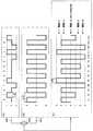
図8に示すように、送信側の構成には、分配器202と、3B4B符号化器204、210、ラッチ回路206、212、222と、P/S変換部208、214と、アッテネータ216と、加算器218、220、224、226と、が含まれる。 As shown in FIG. 8, the transmission side configuration includes a
なお、以下の説明では、3ビットのビット列を4シンボルの2値シンボル列に変換する3B4B変換をベースとする符号化方法を例に挙げるが、本実施形態に係る技術の適用範囲はこれに限定されない。例えば、5ビットのビット列を6シンボルの2値シンボル列に変換する5B6B変換等を利用することも可能である。 In the following description, an encoding method based on 3B4B conversion that converts a 3-bit bit string into a 4-symbol binary symbol string is taken as an example, but the scope of application of the technique according to the present embodiment is limited to this. Not. For example, 5B6B conversion that converts a 5-bit bit string into a 6-symbol binary symbol string can also be used.
また、ここでは入力データを2系統に分配する構成を例示するが、N系統(N≧3)に分配する構成へと拡張することも可能である。但し、このような拡張を行う場合、系統毎に異なる割合でシンボル値を調整する必要がある点に注意されたい。ここでは2系統に分配する構成を例示する。 In addition, here, the configuration in which the input data is distributed to the two systems is illustrated, but the configuration can be extended to a configuration in which the input data is distributed to the N systems (N ≧ 3). However, it should be noted that when performing such an extension, it is necessary to adjust the symbol value at a different rate for each system. Here, a configuration for distributing to two systems is illustrated.
まず、入力データは、分配器202により2系統に分配される。例えば、分配器202は、入力データを3ビット単位で取り込み、取り込んだ3ビットのビット列を交互に3B4B符号化器204、210に入力する。分配器202により分配された3ビットのビット列が入力されると、3B4B符号化器204、210は、3ビットのビット列を3B4B変換して4シンボルの2値シンボル列を生成する。 First, input data is distributed by the
このとき、3B4B符号化器204、210は、図9に示す3B4B変換用の変換テーブルを参照する。例えば、10進数の「3」に対応する3ビットのビット列が入力された場合、3B4B符号化器204、210は、図9の変換テーブルを参照し、4シンボルの2値シンボル列{−1,−1,+1,+1}を出力する。但し、後述する極性反転信号が入力された場合、3B4B符号化器204、210は、極性反転信号の入力値に応じて4シンボルの2値シンボル列の極性を反転した上で出力する。 At this time, the
このようにして3B4B符号化器204、210により出力された4シンボルの2値シンボル列は、それぞれラッチ回路206、212に入力され、タイミングを揃えて出力される。ラッチ回路206、212から出力された2値シンボル列は、それぞれP/S変換部208、214に入力される。P/S変換部208、214に入力された2値シンボル列は、パラレルデータからシリアルデータに変換される。P/S変換部208によりシリアルデータに変換された2値シンボル列(以下、2値シンボル列BS1)は、加算器218に入力される。また、P/S変換部214によりシリアルデータに変換された2値シンボル列は、アッテネータ216に入力される。 The 4-symbol binary symbol sequences output by the
アッテネータ216は、入力された2値シンボル列に含まれる各シンボル値を1/K(図8の例ではK=2)に低減させる。アッテネータ216によりシンボル値が1/Kに低減された2値シンボル列(以下、2値シンボル列BS2)は、加算器218に入力される。上記の通り、加算器218には、2値シンボル列BS1と、シンボル値が1/Kに変換された2値シンボル列BS2とが入力される。これら2値シンボル列BS1、BS2が入力されると、加算器218は、2値シンボル列BS1、BS2を同期加算して加算信号を生成する。例えば、図10(A)に示す2値シンボル列BS1と、図10(B)に示す2値シンボル列BS2とが入力されると、加算器218は、図10(C)に示す4値の加算信号を生成する。 The
加算器218により生成された加算信号は、出力信号として受信側に伝送される。また、この加算信号は、加算器220に入力される。加算器220は、加算器218から出力される加算信号を積算する。また、加算器220により積算された信号は、ラッチ回路222に入力される。ラッチ回路222は、入力された信号を1ワードの境界でラッチし、極性反転信号として3B4B符号化器204に入力する。3B4B符号化器204は、極性反転信号が正値の場合に2値シンボル列をそのまま出力し、極性反転信号が負値の場合に2値シンボル列の極性を反転して出力する。 The addition signal generated by the
また、極性反転信号は、加算器226に入力される。また、加算器226には、極性反転信号と共に加算器224の出力信号が入力される。加算器226は、極性反転信号と、加算器224の出力信号とを加算し、その加算値を3B4B符号化器210に入力する。加算器224には、3B4B符号化器204の出力信号が入力される。そして、加算器224は、3B4B符号化器204の出力信号を1ワード分だけ積算する。この積算値が加算器226に入力されて極性反転信号(前ワードに対するもの)に加算されるため、その加算値を用いると、現ワードに対応する3B4B符号化器204の出力を考慮した3B4B符号化器210の極性反転制御を行うことができる。 The polarity inversion signal is input to the
以上、本実施形態に係る符号化方法、及び信号伝送方法を実現することが可能な送信側の構成について説明した。上記の方法を用いることで、6ビット(3ビット+3ビット)のビット列を4シンボル期間で伝送することができるようになり、AMI符号に基づく伝送信号をそのまま伝送する場合に比べ、6/4=1.5倍の伝送速度が得られる。また、極性反転信号による2値シンボル列の極性反転制御が行われることにより、受信側に伝送される加算信号のDCバランスを良好に保つことが可能になる。 The configuration on the transmission side that can realize the encoding method and the signal transmission method according to the present embodiment has been described above. By using the above method, a bit string of 6 bits (3 bits + 3 bits) can be transmitted in a 4-symbol period. Compared to a case where a transmission signal based on an AMI code is transmitted as it is, 6/4 = A transmission rate of 1.5 times can be obtained. Further, by performing polarity inversion control of the binary symbol sequence by the polarity inversion signal, it is possible to maintain a good DC balance of the addition signal transmitted to the reception side.
さらに、図9の例からも分かる通り、8B6T変換の変換テーブルに比べ、変換テーブルのサイズが格段に小さい。このように変換テーブルのサイズを小さくすることで、回路規模が縮小され、コストの低減に繋がる。なお、図8の例では3B4B符号化に係る構成要素を2つずつ設けているが、2系統のデータを時分割処理することにより、3B4B符号化に係る構成要素を1つに纏めることもできる。 Further, as can be seen from the example of FIG. 9, the size of the conversion table is much smaller than that of the 8B6T conversion table. By reducing the size of the conversion table in this way, the circuit scale is reduced, leading to cost reduction. In addition, in the example of FIG. 8, two components related to 3B4B encoding are provided, but it is also possible to combine the components related to 3B4B encoding into one by performing time-sharing processing on two systems of data. .
(スペクトルの比較)
ここで、図11A、図11Bを参照しながら、本実施形態に係る符号化方法により得られる4値信号(上記の加算信号)の周波数スペクトラムと、AMI符号に基づく伝送信号の周波数スペクトラムとを比較する。図11Aは、AMI符号に基づく伝送信号の周波数スペクトラムである。一方、図11Bは、本実施形態に係る符号化方法により得られた4値信号の周波数スペクトラムである。AMI符号はDC成分を含まない符号である。そのため、図11Aに示すように周波数スペクトラムは、DC成分が十分に抑圧されたものとなる。また、本実施形態に係る4値信号は。上記の通り、極性反転信号によるDCバランスの調整が行われている。そのため、図11Bに示すように、周波数スペクトラムは、AMI符号の場合と同様に、DC成分が十分に抑圧されたものとなる。(Spectral comparison)
Here, referring to FIGS. 11A and 11B, the frequency spectrum of the quaternary signal (the above addition signal) obtained by the encoding method according to the present embodiment is compared with the frequency spectrum of the transmission signal based on the AMI code. To do. FIG. 11A shows a frequency spectrum of a transmission signal based on the AMI code. On the other hand, FIG. 11B is a frequency spectrum of a quaternary signal obtained by the encoding method according to the present embodiment. The AMI code is a code that does not include a DC component. Therefore, as shown in FIG. 11A, the frequency spectrum has a DC component sufficiently suppressed. Also, the quaternary signal according to the present embodiment. As described above, the DC balance is adjusted by the polarity inversion signal. Therefore, as shown in FIG. 11B, the DC spectrum is sufficiently suppressed as in the case of the AMI code in the frequency spectrum.
以上、本実施形態に係る符号化方法について説明した。 The encoding method according to this embodiment has been described above.
[2−2:復号方法]
次に、本実施形態に係る復号方法について説明する。上記の通り、本実施形態に係る符号化方法により生成された加算信号は、図10(C)に示すような4値信号である。また、加算信号が取り得る各振幅値は、2値シンボル列BS1、BS2に含まれるシンボル値の組み合わせに対応する。[2-2: Decoding method]
Next, the decoding method according to this embodiment will be described. As described above, the addition signal generated by the encoding method according to the present embodiment is a quaternary signal as illustrated in FIG. Each amplitude value that can be taken by the addition signal corresponds to a combination of symbol values included in the binary symbol strings BS1 and BS2.
2値シンボル列BS1に含まれるシンボル値が−1又は+1を取る場合、2値シンボル列BS2に含まれるシンボル値は、−0.5又は+0.5を取る。そのため、2値シンボル列BSと2値シンボル列BS2とを加算した加算信号の振幅値は、−1.5、−0.5、+0.5、+1.5のいずれかとなる。そして、加算信号の振幅値−1.5は(−1.0,−0.5)の組み合わせに対応する。同様に、加算信号の振幅値−0.5、+0.5、+1.5は、それぞれ(−1.0,+0.5)、(+1.0,−0.5)、(+1.0,+0.5)の組み合わせに対応する。従って、図13に示すように、3つの閾値+1、0、−1を用いて閾値判定を行うことにより、加算信号から2値シンボル列BS1(上位)、BS2(下位)を復元することができる。 When the symbol value included in the binary symbol sequence BS1 takes −1 or +1, the symbol value included in the binary symbol sequence BS2 takes −0.5 or +0.5. Therefore, the amplitude value of the addition signal obtained by adding the binary symbol sequence BS and the binary symbol sequence BS2 is any one of −1.5, −0.5, +0.5, and +1.5. The amplitude value −1.5 of the addition signal corresponds to the combination (−1.0, −0.5). Similarly, the amplitude values −0.5, +0.5, +1.5 of the added signal are (−1.0, +0.5), (+1.0, −0.5), (+1.0, +0.5). Therefore, as shown in FIG. 13, by performing threshold determination using three thresholds +1, 0, and −1, the binary symbol sequence BS1 (upper) and BS2 (lower) can be restored from the added signal. .
(受信側の構成)
ここで、図12を参照しながら、本実施形態に係る復号方法を実現することが可能な受信側の構成について、具体例を挙げて説明する。図12は、本実施形態に係る復号方法を実現することが可能な受信側の構成例を示す説明図である。例えば、この構成は、携帯端末10のデシリアライザ30に適用可能である。(Receiver configuration)
Here, with reference to FIG. 12, a configuration on the receiving side capable of realizing the decoding method according to the present embodiment will be described with a specific example. FIG. 12 is an explanatory diagram illustrating a configuration example on the reception side capable of realizing the decoding method according to the present embodiment. For example, this configuration can be applied to the
図12に示すように、受信側の構成には、比較器232、238、240と、S/P変換部234、246と、3B4B復号器236、248と、セレクタ242と、合成回路250と、が含まれる。 As shown in FIG. 12, the configuration on the receiving side includes
送信側から伝送された加算信号(受信信号)は、比較器232、238、240に入力される。加算信号が入力されると、比較器232は、加算信号の振幅値を閾値0と比較する。加算信号の振幅値が閾値0よりも大きい場合、比較器232は、判定結果1を出力する。一方、加算信号の振幅値が閾値0よりも小さい場合、比較器232は、判定結果−1を出力する。図13に示すように、加算信号の振幅値が閾値0より大きい場合、2値シンボル列BS1のシンボル値(上位)は1となる。逆に、加算信号の振幅値が閾値0より小さい場合、2値シンボル列BS1のシンボル値(上位)は0となる。つまり、比較器232による判定結果は、そのまま2値シンボル列BS1の復元値となる。 The addition signal (reception signal) transmitted from the transmission side is input to the
比較器232の判定結果は、S/P変換部234、及びセレクタ242に入力される。判定結果(復元値)が入力されると、S/P変換部234は、シリアルデータを4シンボル単位のパラレルデータに変換する。そして、S/P変換部234は、パラレルデータに変換した復元値を3B4B復号器236に入力する。復元値が入力されると、3B4B復号器236は、図9に示した変換テーブルを参照し、4シンボルの復元値を3ビットのビット列に変換する。そして、3B4B復号器236は、3ビットのビット列を合成回路250に入力する。 The determination result of the
一方、比較器238は、加算信号の振幅値を閾値+1と比較する。そして、比較器238による比較の結果は、セレクタ242に入力される。同様に、比較器240は、加算信号の振幅値を閾値−1と比較する。そして、比較器240による比較の結果は、セレクタ242に入力される。上記の通り、セレクタ242には、比較器232、238、240による比較の結果が入力される。セレクタ242は、これら比較の結果から2値シンボル列BS2のシンボル値を復元する。但し、セレクタ242は、1/Kに低減されていたシンボル値を元に戻した状態の2値シンボル列(以下、2値シンボル列BS2’)を復元する。セレクタ242は、加算信号の振幅値が+1.5、−0.5である場合に復元値1を出力し、加算信号の振幅値が+0.5、−1.5である場合に復元値−1を出力する。 On the other hand, the
セレクタ242により出力された復元値は、S/P変換部246に入力される。復元値が入力されると、S/P変換部246は、シリアルデータを4シンボル単位のパラレルデータに変換する。そして、S/P変換部246は、パラレルデータに変換した復元値を3B4B復号器248に入力する。復元値が入力されると、3B4B復号器248は、図9に示した変換テーブルを参照し、4シンボルの復元値を3ビットのビット列に変換する。そして、3B4B復号器248は、3ビットのビット列を合成回路250に入力する。そして、合成回路250は、3B4B復号器236から入力されたビット列と、3B4B復号器248から入力されたビット列とを交互に出力する。その結果、入力データが復元される。 The restored value output by the
以上、本実施形態に係る復号方法を実現することが可能な受信側の構成について説明した。上記の方法を用いることで、加算信号から入力データを復元することができる。 The configuration on the receiving side that can realize the decoding method according to the present embodiment has been described above. By using the above method, input data can be restored from the addition signal.
以上、本発明の第1実施形態について説明した。本実施形態の構成を適用することにより、AMI符号に基づく伝送信号をそのまま伝送する場合に比べ、1.5倍の伝送速度が得られる。また、2値シンボル列の極性反転制御が行われることにより、受信側に伝送される加算信号のDCバランスを良好に保つことが可能になる。その結果、直流遮断の伝送路においても伝送品質を良好に保つことが可能になる。 The first embodiment of the present invention has been described above. By applying the configuration of the present embodiment, a transmission rate 1.5 times higher than that in the case where the transmission signal based on the AMI code is transmitted as it is can be obtained. Further, by performing polarity inversion control of the binary symbol sequence, it is possible to maintain a good DC balance of the addition signal transmitted to the reception side. As a result, it is possible to maintain good transmission quality even in a DC cutoff transmission line.
<3:第2実施形態>
次に、本発明の第2実施形態について説明する。本実施形態の技術は、例えば、上記の携帯端末10におけるシリアル信号ライン28を通じたデータ伝送に適用可能である。上記第1実施形態と同様、本実施形態においては、サイズの小さな変換テーブルを利用して、伝送信号の周波数スペクトルを広帯域化させずに伝送速度を向上させることが可能な符号化方法を提案する。また、DC遮断特性の伝送路における信号伝送が想定されているため、本実施形態の技術は、さらに、このような伝送路において伝送品質の劣化を招かず、周波数スペクトルの広帯域化を回避しつつ、伝送速度を向上させることを目的とする。<3: Second Embodiment>
Next, a second embodiment of the present invention will be described. The technique of the present embodiment is applicable to data transmission through the
[3−1:符号化方法]
まず、本実施形態に係る符号化方法について説明する。本実施形態に係る符号化方法は、入力されたビット列をN系統(N≧2)に分配して符号化するものである。また、本実施形態に係る符号化方法は、各系統のシンボル列を1/Nシンボル期間ずつ異なるタイミングに調整するステップを含む。このステップでタイミング調整が行われたN系統のシンボル列に基づく伝送信号は、加算されて、例えば、シリアル信号ライン28を通じて伝送される。なお、系統毎にシンボル列のタイミングが1/Nシンボル期間ずつ異なっているため、N系統の伝送信号を加算したとしても、各系統のシンボル列を容易に復元することができる。このように、N系統を加算して伝送することにより、1シンボル期間に伝送されるシンボル数をN倍にすることができる。以下、具体例を挙げて説明する。[3-1: Encoding method]
First, the encoding method according to the present embodiment will be described. In the encoding method according to the present embodiment, an input bit string is distributed and encoded into N systems (N ≧ 2). In addition, the encoding method according to the present embodiment includes a step of adjusting the symbol strings of each system at different timings by 1 / N symbol periods. The transmission signals based on the N-system symbol strings whose timings have been adjusted in this step are added and transmitted through, for example, the
(送信側の構成)
まず、図14を参照しながら、本実施形態に係る符号化方法、及び信号伝送方法を実現することが可能な送信側の構成について、具体例を挙げて説明する。図14は、本実施形態に係る符号化方法、及び信号伝送方法を実現することが可能な送信側の構成例を示す説明図である。例えば、この構成は、携帯端末10のシリアライザ26に適用可能である。(Sender configuration)
First, with reference to FIG. 14, a configuration on the transmission side capable of realizing the encoding method and the signal transmission method according to the present embodiment will be described with a specific example. FIG. 14 is an explanatory diagram illustrating a configuration example on the transmission side capable of realizing the encoding method and the signal transmission method according to the present embodiment. For example, this configuration is applicable to the
図14に示すように、送信側の構成には、分配器302と、3B4B符号化器304、306と、遅延回路308と、加算器310と、同期信号発生回路312と、選択回路314と、が含まれる。 As shown in FIG. 14, the configuration on the transmission side includes a
なお、以下の説明では、3ビットのビット列を4シンボルの2値シンボル列に変換する3B4B変換をベースとする符号化方法を例に挙げるが、本実施形態に係る技術の適用範囲はこれに限定されない。例えば、5ビットのビット列を6シンボルの2値シンボル列に変換する5B6B変換等を利用することも可能である。 In the following description, an encoding method based on 3B4B conversion that converts a 3-bit bit string into a 4-symbol binary symbol string is taken as an example, but the scope of application of the technique according to the present embodiment is limited to this. Not. For example, 5B6B conversion that converts a 5-bit bit string into a 6-symbol binary symbol string can also be used.
また、ここでは入力データを2系統に分配する構成を例示するが、N系統(N≧3)に分配する構成へと拡張することも可能である。但し、このような拡張を行う場合、系統毎に1/Nシンボル期間ずつ異なるタイミングとなるよう、タイミングを調整する必要がある点に注意されたい。ここでは2系統に分配する構成を例示する。 In addition, here, the configuration in which the input data is distributed to the two systems is illustrated, but the configuration can be extended to a configuration in which the input data is distributed to the N systems (N ≧ 3). However, it should be noted that when such an extension is performed, it is necessary to adjust the timing so that the 1 / N symbol period differs for each system. Here, a configuration for distributing to two systems is illustrated.
まず、入力データは、分配器302により2系統に分配される。例えば、分配器302は、入力データを3ビット単位で取り込み、取り込んだ3ビットのビット列を交互に3B4B符号化器304、306に入力する。分配器302により分配された3ビットのビット列が入力されると、3B4B符号化器304、306は、3ビットのビット列を3B4B変換して4シンボルの2値シンボル列を生成する。このとき、3B4B符号化器304、306は、図9に示す3B4B変換用の変換テーブルを参照する。例えば、10進数の「3」に対応する3ビットのビット列が入力された場合、3B4B符号化器304、306は、図9の変換テーブルを参照し、4シンボルの2値シンボル列{−1,−1,+1,+1}を出力する。 First, input data is distributed to two systems by a
3B4B符号化器304により出力された2値シンボル列BS1は、加算器310に入力される。また、3B4B符号化器304により出力された2値シンボル列BS2は、遅延回路308に入力される。2値シンボル列BS2が入力されると、遅延回路308は、2値シンボル列BS2を1/2シンボル期間だけ遅延させる。そして、遅延回路308は、1/2シンボル期間だけ遅延させた2値シンボル列BS2を加算器310に入力する。2値シンボル列BS1、BS2が入力されると、加算器310は、これら2値シンボル列BS1、BS2を加算して加算信号を生成する。そして、加算器310は、生成した加算信号を選択回路314に入力する。 The binary symbol sequence BS1 output by the
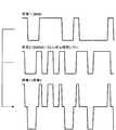
ここで、図15を参照しながら、加算器310から出力される加算信号の特性について説明を補足する。図15には、3B4B符号化器304から出力された2値シンボル列BS1に相当するデータ列Aの信号波形と、遅延回路308から出力された2値シンボル列BS2に相当するデータ列Bの信号波形とが例示されている。さらに、図15には、データ列Aの信号波形とデータ列Bの信号波形とを加算した加算信号(データ列A+データ列B)の信号波形が示されている。なお、図15に示した波線の1つの間隔は、1/2シンボル期間を表している。 Here, the characteristic of the added signal output from the
図15の例からも分かるように、加算器310から出力される加算信号は、3値の信号となる。例えば、2値シンボル列BS1、BS2のシンボル値を+1、−1とすると、加算信号の振幅値は+2、0、−2のいずれかとなる。また、加算信号の周波数スペクトラムは、図16Bのようになる。図16Aに示した2値符号(3B4B符号)の周波数スペクトラムと比較しても、加算信号の周波数スペクトラムには周波数帯域の広がりも見られず、DC成分も十分に抑制されていることが分かる。 As can be seen from the example of FIG. 15, the addition signal output from the
再び図14を参照する。同期信号発生回路312は、データの送信時に同期信号を発生させる。そして、同期信号発生回路312は、発生した同期信号を選択回路314に入力する。選択回路314は、同期信号発生回路312により入力された同期信号を出力した後、加算器310から入力された加算信号を出力する。選択回路314から出力された信号は、例えば、シリアル伝送ライン28を通じて受信側に伝送される。 Refer to FIG. 14 again. The synchronization
以上、本実施形態に係る符号化方法、及び信号伝送方法を実現することが可能な送信側の構成について説明した。上記の方法を用いることで、6ビット(3ビット+3ビット)のビット列を4シンボル期間で伝送することができるようになり、AMI符号に基づく伝送信号をそのまま伝送する場合に比べ、6/4=1.5倍の伝送速度が得られる。また、図16Bに示すように、加算信号のDCバランスを良好に保つことが可能になる。 The configuration on the transmission side that can realize the encoding method and the signal transmission method according to the present embodiment has been described above. By using the above method, a bit string of 6 bits (3 bits + 3 bits) can be transmitted in a 4-symbol period. Compared to a case where a transmission signal based on an AMI code is transmitted as it is, 6/4 = A transmission rate of 1.5 times can be obtained. In addition, as shown in FIG. 16B, the DC balance of the addition signal can be kept good.
[3−2:復号方法]
次に、本実施形態に係る復号方法について説明する。上記の通り、本実施形態に係る符号化方法により生成された加算信号は、図15(データ列A+データ列B)に示すような3値信号である。2値シンボル列BS1、BS2のシンボル値は、1/2シンボル期間毎に検出される加算信号の振幅値から算出することができる。[3-2: Decoding method]
Next, the decoding method according to this embodiment will be described. As described above, the addition signal generated by the encoding method according to the present embodiment is a ternary signal as shown in FIG. 15 (data string A + data string B). The symbol values of the binary symbol strings BS1 and BS2 can be calculated from the amplitude value of the addition signal detected every ½ symbol period.
例えば、2値シンボル列BS1の各シンボル値をA11、A12、…、A1Lと表現し、2値シンボル列BS2のシンボル値をA21、A22、…、A2Lと表現する。また、1/2シンボル期間を単位として加算信号の振幅値をX(1)、X(2)、…、X(2*L)と表現する。上記の通り、2値シンボル列BS2は、1/2シンボル期間だけ遅延されている。そのため、X(1)=A11+α、X(2)=A11+A21、X(3)=A21+A12、…となる。但し、αは初期値である。 For example, the symbol values of the binary symbol sequence BS1 are expressed as A11, A12,..., A1L, and the symbol values of the binary symbol sequence BS2 are expressed as A21, A22,. Further, the amplitude value of the addition signal is expressed as X (1), X (2),..., X (2 * L) in units of ½ symbol period. As described above, the binary symbol sequence BS2 is delayed by a 1/2 symbol period. Therefore, X (1) = A11 + α, X (2) = A11 + A21, X (3) = A21 + A12,. Here, α is an initial value.
まず、(ステップS1)加算信号の振幅値X(1)から2値シンボル列BS1のシンボル値A11が決まる。次いで、(ステップS2)加算信号の振幅値X(2)及びステップS1で決まった2値シンボル列BS1のシンボル値A11から2値シンボル列BS2のシンボル値A21が決まる。次いで、(ステップS3)加算信号の振幅値X(3)及びステップS2で決まった2値シンボル列BS2のシンボル値A21から2値シンボル列BS1のシンボル値A12が決まる。このような処理を順次繰り返すことにより、加算信号の振幅値から交互に2値シンボル列BS1、BS2のシンボル値を算出することができる。 First, (step S1) The symbol value A11 of the binary symbol string BS1 is determined from the amplitude value X (1) of the added signal. Next, (step S2) the symbol value A21 of the binary symbol sequence BS2 is determined from the amplitude value X (2) of the added signal and the symbol value A11 of the binary symbol sequence BS1 determined in step S1. Next, (step S3) the symbol value A12 of the binary symbol sequence BS1 is determined from the amplitude value X (3) of the added signal and the symbol value A21 of the binary symbol sequence BS2 determined in step S2. By sequentially repeating such processing, the symbol values of the binary symbol strings BS1 and BS2 can be calculated alternately from the amplitude value of the added signal.
しかしながら、この方法はやや複雑である。そこで、本件発明者は、本実施形態では2値シンボル列を扱っていることに注目し、加算信号の振幅変化から順次2値シンボル列を復元する方法を考案した。この方法では、2値シンボル列BS1、BS2に含まれる第1番目のシンボル値A11、A21に初期値を設定しておく必要がある。しかし、初期値が設定されていれば、加算信号の振幅値が変化したか否かを判断することにより、第2番目のシンボル値A12、A22が決まる。同様に、第3番目以降のシンボル値も決まる。 However, this method is somewhat complicated. In view of this, the present inventors paid attention to the fact that the present embodiment deals with binary symbol sequences, and devised a method for sequentially restoring binary symbol sequences from the amplitude change of the added signal. In this method, it is necessary to set initial values for the first symbol values A11 and A21 included in the binary symbol strings BS1 and BS2. However, if the initial value is set, the second symbol values A12 and A22 are determined by determining whether or not the amplitude value of the added signal has changed. Similarly, the third and subsequent symbol values are also determined.
例えば、初期値A11=A21=1とし、X(1)=A11+A21、X(2)=A12+A21、X(3)=A12+A22、X(4)=A13+A22、…とすると、X(1)→X(2)が変化した場合、A12=−1に決まる。X(2)→X(3)が変化した場合、A22=−1に決まる。このように、加算信号の振幅変化を順次検出することにより、2値シンボル列BS1、BS2を復元することができる(図18を参照)。 For example, assuming that the initial value A11 = A21 = 1, and X (1) = A11 + A21, X (2) = A12 + A21, X (3) = A12 + A22, X (4) = A13 + A22,. When 2) changes, A12 = −1. When X (2) → X (3) changes, A22 = −1. Thus, the binary symbol strings BS1 and BS2 can be restored by sequentially detecting the amplitude change of the added signal (see FIG. 18).
(受信側の構成)
ここで、図17を参照しながら、本実施形態に係る復号方法を実現することが可能な受信側の構成について、具体例を挙げて説明する。図17は、本実施形態に係る復号方法を実現することが可能な受信側の構成例を示す説明図である。例えば、この構成は、携帯端末10のデシリアライザ30に適用可能である。(Receiver configuration)
Here, with reference to FIG. 17, a configuration on the receiving side capable of realizing the decoding method according to the present embodiment will be described with a specific example. FIG. 17 is an explanatory diagram illustrating a configuration example on the reception side capable of realizing the decoding method according to the present embodiment. For example, this configuration can be applied to the
図17に示すように、受信側の構成には、同期信号検出回路322と、減算器324と、遅延回路326と、絶対値回路328と、クロック再生部330と、2分周回路332と、トグル回路334、338と、3B4B復号器336、340と、セレクタ342と、が含まれる。 As shown in FIG. 17, the configuration on the receiving side includes a synchronization
送信側から伝送された同期信号及び加算信号(受信信号)は、同期信号検出回路322、減算器324、遅延回路326、及びクロック再生部330に入力される。まず、受信信号が入力されると、同期信号検出回路322は、受信信号から同期信号を検出する。そして、同期信号検出回路322は、同期信号を検出すると、トグル回路334、338をセットする。また、受信信号が入力されると、クロック再生部330は、受信信号からシンボルクロックを再生する。但し、ここで再生されるシンボルクロックの1周期は、2値シンボル列BS1、BS2の1シンボル期間に相当する。 The synchronization signal and the addition signal (reception signal) transmitted from the transmission side are input to the synchronization
クロック再生部330は、再生したシンボルクロックを遅延回路326、2分周回路332、及びトグル回路334、338に入力する。但し、トグル回路334、338には、反転されたシンボルクロックが入力される。受信信号及びシンボルクロックが入力されると、遅延回路326は、シンボルクロックの半周期分だけ受信信号を遅延させる。そして、遅延回路326は、遅延した受信信号を減算器324に入力する。非遅延の受信信号、及び遅延回路326により遅延された受信信号が入力されると、減算器324は、非遅延の受信信号から遅延された受信信号を減算する。そして、減算器324は、減算結果(以下、減算値)を絶対値回路328に入力する。 The
絶対値回路328は、減算器324により入力された減算値の絶対値を算出し、トグル回路334、338に入力する。また、2分周回路332は、クロック再生部330により再生されたシンボルクロックに基づいてシンボル毎に反転する信号を生成し、トグル回路334、338のイネーブル端子(EN)に入力する。但し、ここでトグル回路338に入力される信号は、反転されてから入力される。トグル回路334、338は、ENが1の場合に動作し、Tが1の場合に反転する動作を行う。そのため、トグル回路334、338は、2分周回路332の出力に応じて交互に動作する。また、トグル回路334、338は、絶対値回路328の出力が1の場合に反転し、0の場合に反転しない動作を行う。そして、トグル回路334、338の出力は、それぞれ3B4B復号器336、340に入力される。 The
3B4B復号器336、340は、図9に示した変換テーブルを参照し、それぞれ4シンボルの2値シンボル列BS1、BS2を3ビットのビット列に変換する。そして、3B4B復号器336、340は、それぞれ3ビットのビット列をセレクタ342に入力する。ビット列が入力されると、セレクタ342は、3B4B復号器336から入力されたビット列と、3B4B復号器340から入力されたビット列とを交互に出力する。その結果、入力データ(受信データ)が復元される。 The 3B4B decoders 336 and 340 refer to the conversion table shown in FIG. 9 and convert the 4-symbol binary symbol sequences BS1 and BS2 to 3-bit bit sequences, respectively. Each of the
ここで、図18を参照しながら、本実施形態に係る復号方法について説明を補足する。図18には、加算信号の波形、加算信号から復元される2値シンボル列BS1、BS2(データ列A、B)、及び加算信号に基づいて再生されるシンボルクロックの波形が示されている。なお、図18の例では、データ列A、Bの初期値が1に設定されている。 Here, the description of the decoding method according to the present embodiment will be supplemented with reference to FIG. FIG. 18 shows the waveform of the addition signal, binary symbol sequences BS1 and BS2 (data sequences A and B) restored from the addition signal, and the waveform of the symbol clock reproduced based on the addition signal. In the example of FIG. 18, the initial values of the data strings A and B are set to 1.
但し、初期値は、必ずしも1に設定されている必要はなく、例えば、−1に設定されていてもよい。つまり、データ列A、Bに共通の所定値が設定されていればよい。仮に、初期値の組み合わせを(+1,−1)にすると、加算信号の振幅値は0となる。この場合、初期値が(+1,−1)であるか、(−1,+1)であるかが不定になる。 However, the initial value is not necessarily set to 1 and may be set to −1, for example. That is, a predetermined value common to the data strings A and B may be set. If the combination of the initial values is (+1, −1), the amplitude value of the added signal is 0. In this case, it is undefined whether the initial value is (+1, -1) or (-1, +1).
上記の通り、同期信号が検出されると、トグル回路334、338がセットされる。このとき、トグル回路334、338の初期値が1に設定される。このようにして初期値を設定した上で、1シンボル毎に受信信号の変化を調べることにより、データ列A、Bの値が交互に得られる。例えば、図18の例では、第1番目のタイミングで受信信号が1から0に変化している。そのため、データ列Aが1から−1に変化したことが分かる。次に、第2番目のタイミングを参照すると、このタイミングで受信信号が0から−1に変化している。そのため、データ列Bが1から−1に変化したことが分かる。順次、このような処理ステップを繰り替えることにより、データ列A、Bが復元される。 As described above, when the synchronization signal is detected, the
以上、本実施形態に係る復号方法、及びその復号方法を実現することが可能な受信側の構成について説明した。 The decoding method according to the present embodiment and the configuration on the receiving side that can implement the decoding method have been described above.
[3−3:変形例]
次に、図19を参照しながら、本実施形態の一変形例に係る受信側の構成について説明する。図19は、本実施形態の一変形例に係る受信側の構成例を示す説明図である。この変形例は、入力データを3以上の系統に分配した場合への拡張構成に関する。なお、入力データを3以上の系統に分配する場合、送信側の構成は、図14に示した構成のうち、3B4B符号化器306及び遅延回路308で構成される処理ブロックと同等の機能ブロックを増加した系統数分だけ追加すればよい。但し、j番目の系統に設定される遅延時間は、(j−1)/Nシンボル時間(j=1〜N;Nは系統数)となる。[3-3: Modification]
Next, a configuration on the receiving side according to a modification of the present embodiment will be described with reference to FIG. FIG. 19 is an explanatory diagram illustrating a configuration example on the reception side according to a modification of the present embodiment. This modification relates to an extended configuration in the case where input data is distributed to three or more systems. Note that when the input data is distributed to three or more systems, the transmission side configuration includes functional blocks equivalent to the processing blocks configured by the
一方、受信側の構成は、図19のようになる。図19に示すように、受信側の構成には、同期信号検出回路352と、クロック再生部354と、タイミング生成回路356と、反転回路358、360、362と、加算器364と、判定回路366と、レジスタ368、372、376と、復号器370、374、378と、セレクタ380と、が含まれる。 On the other hand, the configuration on the receiving side is as shown in FIG. As shown in FIG. 19, the configuration on the receiving side includes a synchronization
受信信号は、同期信号検出回路352、加算器364、及びクロック再生部354に入力される。クロック再生部354は、受信信号に同期したシンボルクロックを再生する。そして、クロック再生部354は、再生したシンボルクロックをタイミング生成回路356に入力する。シンボルクロックが入力されると、タイミング生成回路356は、シンボルクロックに基づいて個々の回路の動作に用いるタイミング信号を生成する。そして、タイミング生成回路356は、生成したタイミング信号を反転回路358、360、362、レジスタ368、372、376に入力する。 The received signal is input to the synchronization
また、同期検出回路352は、受信信号から同期信号を検出する。同期信号を検出すると、同期検出回路352は、検出した同期信号をレジスタ368、372、376に入力する。同期信号が入力されると、レジスタ368、372、376は初期化される。また、反転回路358、360、362は、タイミング生成回路356により入力されるタイミング信号がイネーブルの場合に、レジスタ368、372、376の出力を反転して出力する。一方、タイミング信号がディセーブルの場合には0が出力される。 Further, the
また、加算器364は、受信信号と、反転回路358、360、362の出力信号とを加算し、判定回路366に入力する。判定回路366は、入力信号の符号(+/−)を判定し、その判定結果をレジスタ368、372、376に入力する。そして、レジスタ368、372、376のうち、タイミング生成回路356からタイミング信号を用いて指定されたレジスタが、判定回路366により入力された判定結果を取り込む。例えば、レジスタ368が判定回路366により入力された判定結果を取り込む。 The
レジスタ368が判定回路366により入力された判定結果を取り込んだ場合、レジスタ368の出力は、復号器370、及び反転回路362に入力される。また、レジスタ372が判定回路366により入力された判定結果を取り込んだ場合、レジスタ372の出力は、復号器374、及び反転回路360に入力される。さらに、レジスタ376が判定回路366により入力された判定結果を取り込んだ場合、レジスタ376の出力は、復号器378、及び反転回路358に入力される。 When the
復号器370、374、378は、それぞれタイミング生成回路356によりタイミング信号を用いて指定されたタイミングで復号処理を実行する。そして、復号器370、374、378は、復号結果をセレクタ380に入力する。セレクタ380は、タイミング生成回路356によりタイミング信号を用いて指定されたタイミング(順番)で復号器370、374、378から入力された復号結果を出力する。その結果、受信信号から元の入力データが復元される。 Each of the
上記構成の場合、符号化された複数の2値シンボル列が時間的にシフトされて加算される。ある特定系統の2値シンボル列に注目すると、他系統の2値シンボル列が既知であり、それら2系統の2値シンボル列を加算した信号から他系列の2値シンボル列を減じることが出来れば、特定系統の2値シンボル列が抽出される。従って、同期信号により各系統のデータを格納するレジスタを初期化した後、判定する符号以外のレジスタ値を受信信号から減じることで、判定回路により特定系統の2値シンボル列のみを判定することが可能になる。つまり、+、−の2値判定を行うだけで済む。加算器364に入力される反転回路358、360、362の出力データは、判定を行う特定系統について0とされる。そのため、これまでの判定結果に基づいて他の系統のデータが除去される。そして、判定結果は、特定のレジスタのみに格納される。 In the case of the above configuration, a plurality of encoded binary symbol sequences are shifted in time and added. If attention is paid to a binary symbol string of a specific system, if a binary symbol string of another system is known and the binary symbol string of another system can be subtracted from a signal obtained by adding these two system binary symbol strings. A binary symbol string of a specific system is extracted. Therefore, after initializing a register for storing data of each system using a synchronization signal, a determination circuit can determine only a binary symbol string of a specific system by subtracting a register value other than a determination code from the received signal. It becomes possible. That is, it is only necessary to perform binary determination of + and −. The output data of the inverting
以上、本実施形態の一変形例について説明した。このように、本実施形態に係る符号化方法、復号方法は、3以上の系統に入力データを分配して伝送する方法に拡張することができる。 Heretofore, a modification of the present embodiment has been described. As described above, the encoding method and decoding method according to the present embodiment can be extended to a method of distributing input data to three or more systems and transmitting them.
以上、本発明の第2実施形態について説明した。本実施形態の構成を適用することにより、AMI符号に基づく伝送信号をそのまま伝送する場合に比べ、1.5倍の伝送速度が得られる。また、加算信号のDCバランスを良好に保つことが可能になり、直流遮断の伝送路においても伝送品質を良好に保つことが可能になる。 The second embodiment of the present invention has been described above. By applying the configuration of the present embodiment, a transmission rate 1.5 times higher than that in the case where the transmission signal based on the AMI code is transmitted as it is can be obtained. In addition, it is possible to maintain a good DC balance of the addition signal, and it is possible to maintain a good transmission quality even in a DC cutoff transmission path.
<4:まとめ>
最後に、上記の第1及び第2実施形態に含まれる技術的思想について纏める。<4: Summary>
Finally, the technical ideas included in the first and second embodiments will be summarized.
[4−1:ポイントの整理]
まず、上記の第1及び第2実施形態に係る技術のポイントについて整理する。[4-1: Organize points]
First, the technical points according to the first and second embodiments will be summarized.
(第1実施形態のポイント)
上記の第1実施形態は、図21に示すように、入力データを2系統の符号列(符号1、符号2)に分け、その一方(符号2)を1/2の振幅に調整し、他方(符号1)と加算して伝送する信号伝送方法に関する。図21に示すように、符号1+符号2は、4値の符号になる。しかし、1シンボル期間に2倍の符号を伝送することが可能になるため、シンボルクロックを高速化せずに伝送速度を向上させることができる。例えば、3B4B符号を用いた場合、AMI符号を用いる場合に比べて1.5倍の伝送速度が得られる。(Points of the first embodiment)
In the first embodiment, as shown in FIG. 21, the input data is divided into two systems of code strings (
(第2実施形態のポイント)
上記の第2実施形態は、図20に示すように、入力データを2系統の符号列(符号1、符号2)に分け、その一方(符号2)を1/2シンボル時間だけシフトし、他方(符号1)と加算して伝送する信号伝送方法に関する。図20に示すように、符号1+符号2は、3値の符号になる。しかし、1シンボル期間に2倍の符号を伝送することが可能になるため、シンボルクロックを高速化せずに伝送速度を向上させることができる。例えば、3B4B符号を用いた場合、AMI符号を用いる場合に比べて1.5倍の伝送速度が得られる。(Points of the second embodiment)
In the second embodiment, as shown in FIG. 20, the input data is divided into two systems of code strings (
[4−2:表現の整理]
次に、本発明の実施形態に係る技術内容について簡単に纏める。ここで述べる技術内容は、例えば、PC、携帯電話、携帯ゲーム機、携帯情報端末、情報家電、カーナビゲーションシステム等、種々の情報処理装置に対して適用することができる。[4-2: Organizing expressions]
Next, the technical contents according to the embodiment of the present invention will be briefly summarized. The technical contents described here can be applied to various information processing apparatuses such as PCs, mobile phones, portable game machines, portable information terminals, information appliances, car navigation systems, and the like.
(第2実施形態に相当)
上記の情報処理装置の機能構成は次のように表現することができる。当該情報処理装置は、当該情報処理装置は、次のような分配器、符号化部、信号生成部、信号遅延部、信号加算部、及び信号送信部を有する。上記の分配器は、入力データをMビット単位で分配してMビットのビット列をN組生成する。また、上記の符号化部は、前記分配器により分配されたN組のビット列をそれぞれKシンボルの2値シンボル列に変換してN組の2値シンボル列を生成する。このとき、上記の符号化部は、良好なDCバランスを実現可能な符号化方法を利用して、Kシンボルの2値シンボル列が直流成分を含まないように、Mビットのビット列をKシンボルの2値シンボル列に変換する。例えば、上記の3B4B変換や8B10B変換等、様々な符号化方法を適用することが可能である。(Equivalent to the second embodiment)
The functional configuration of the information processing apparatus described above can be expressed as follows. The information processing apparatus includes the following distributor, encoding unit, signal generation unit, signal delay unit, signal addition unit, and signal transmission unit. The distributor distributes input data in units of M bits and generates N sets of M-bit bit strings. The encoding unit converts N sets of bit sequences distributed by the distributor into binary symbol sequences of K symbols to generate N sets of binary symbol sequences. At this time, the encoding unit uses an encoding method capable of realizing a good DC balance, and converts the M-bit bit string of the K symbol so that the binary symbol string of the K symbol does not include a DC component. Convert to binary symbol sequence. For example, various encoding methods such as the 3B4B conversion and the 8B10B conversion described above can be applied.
上記の通り、符号化部によりN組の2値シンボル列が生成される。このN組の2値シンボル列は、上記の信号生成部に入力される。そして、上記の信号生成部は、所定のシンボルクロックに同期し、かつ、前記N組の2値シンボル列に含まれる各シンボル値を振幅値とするN個の送信信号Sj(j=1〜N)を生成する。つまり、上記の信号生成部により、N組の2値シンボル列に相当する信号波形が得られる。そして、上記の信号遅延部は、j=1〜Nの各々に関し、前記信号生成部により生成された送信信号Sjを(j−1)/Nシンボル時間だけ遅延させて遅延信号Rjを生成する。 As described above, N sets of binary symbol sequences are generated by the encoding unit. The N sets of binary symbol sequences are input to the signal generation unit. Then, the signal generation unit synchronizes with a predetermined symbol clock and uses N transmission signals Sj (j = 1 to N) whose amplitude values are the symbol values included in the N sets of binary symbol sequences. ) Is generated. That is, a signal waveform corresponding to N sets of binary symbol sequences is obtained by the signal generation unit. Then, for each of j = 1 to N, the signal delay unit delays the transmission signal Sj generated by the signal generation unit by (j−1) / N symbol time to generate a delay signal Rj.
上記の信号遅延部により生成された遅延信号Rjは、上記の信号加算部に入力される。そして、上記の信号加算部は、前記信号遅延部により生成された遅延信号Rj(j=1〜N)を加算して加算信号を生成する。さらに、上記の信号送信部は、前記信号加算部により生成された加算信号を送信する。このように、本実施形態に係る情報処理装置は、入力データをN個の2値シンボル列に分け、各2値シンボル列のタイミングを1/Nシンボル時間ずつ順にずらし、互いにタイミングのずれたN個の2値シンボル列を加算して送信する構成を有する。 The delayed signal Rj generated by the signal delay unit is input to the signal adder. The signal adding unit adds the delay signals Rj (j = 1 to N) generated by the signal delay unit to generate an addition signal. Further, the signal transmission unit transmits the addition signal generated by the signal addition unit. As described above, the information processing apparatus according to the present embodiment divides input data into N binary symbol sequences, sequentially shifts the timing of each binary symbol sequence by 1 / N symbol time, and shifts N timings that are shifted in timing from each other. The binary symbol sequence is added and transmitted.
ここで、N=2の場合について具体的に考えてみよう。N=2の場合、上記の信号遅延部は、遅延信号R1、R2を生成する。遅延信号R1は無遅延(0シンボル時間の遅延)である。また、遅延信号R2は、遅延信号R1に比べて1/2シンボル時間だけ遅延している。いま、q番目(q=1〜K)のシンボル時間における遅延信号R1の振幅値をA(1,q)、遅延信号R2の振幅値をA(2,q)と表記する。また、1/2シンボル時間毎にサンプリングした加算信号の振幅値(但し、L番目にサンプリングされた振幅値;1≦L≦2*K+1)をX(L)と表記する。 Here, let us specifically consider the case of N = 2. When N = 2, the signal delay unit generates the delay signals R1 and R2. The delay signal R1 is non-delayed (0 symbol time delay). The delayed signal R2 is delayed by ½ symbol time compared to the delayed signal R1. Now, the amplitude value of the delay signal R1 in the q-th (q = 1 to K) symbol time is expressed as A (1, q), and the amplitude value of the delay signal R2 is expressed as A (2, q). Further, the amplitude value of the added signal sampled every 1/2 symbol time (where the Lth sampled amplitude value; 1 ≦ L ≦ 2 * K + 1) is expressed as X (L).
このとき、X(1)=A(1,1)、X(2)=A(1,1)+A(2,1)、X(3)=A(2,1)+A(1,2)、X(4)=A(1,2)+A(2,2)、…、X(2*K)=A(2,K−1)+A(1,K)、X(2*K+1)=A(2,K)となる。但し、X(1)、X(2*K+1)の構成は、初期値の設定方法や回路構成等に応じて適宜変形される。ここでは説明を簡単化するために上記のような構成を例示している。この例の場合、X(1)からA(1,1)を決めることができる。次に、A(1,1)を用いてX(2)からA(2,1)を算出することができる。次に、A(2,1)を用いてX(3)からA(1,2)を算出することができる。同様にしてA(1,q)、A(2,q)(q=1〜K)を算出することができる。つまり、加算信号の振幅値Xに基づいて逐次演算を行うことにより、遅延信号R1、R2を算出することができる。 At this time, X (1) = A (1,1), X (2) = A (1,1) + A (2,1), X (3) = A (2,1) + A (1,2) , X (4) = A (1,2) + A (2,2),..., X (2 * K) = A (2, K-1) + A (1, K), X (2 * K + 1) = A (2, K). However, the configurations of X (1) and X (2 * K + 1) are appropriately modified according to the initial value setting method, circuit configuration, and the like. Here, in order to simplify the description, the above configuration is illustrated. In this example, A (1,1) can be determined from X (1). Next, A (2,1) can be calculated from X (2) using A (1,1). Next, A (1,2) can be calculated from X (3) using A (2,1). Similarly, A (1, q) and A (2, q) (q = 1 to K) can be calculated. That is, the delay signals R1 and R2 can be calculated by performing sequential calculation based on the amplitude value X of the addition signal.
やや複雑になるが、N≧3の場合についても同様にして加算信号の振幅値から遅延信号Rjを算出可能である。N≧3の場合も含めて一般化すると、原理的には、加算信号の振幅値X(L)から遅延信号Rjの振幅値A(p,q)を得る方法は次のようになる。 Although somewhat complicated, the delay signal Rj can be calculated from the amplitude value of the addition signal in the same manner when N ≧ 3. In general, including the case of N ≧ 3, in principle, the method of obtaining the amplitude value A (p, q) of the delayed signal Rj from the amplitude value X (L) of the added signal is as follows.
まず、振幅値X(1)に基づいて振幅値A(1,1)を算出し、
各L(2≦L≦N)に対し、振幅値X(L)、振幅値A(p,1)(p=1〜L−1)に基づいて振幅値A((p+1),1)を算出し、
各Q(1≦Q≦K−1)に対し、振幅値X(Q*N+1)、振幅値A(p,q)(p=1〜N、q=1〜Q)に基づいて振幅値A(1,(Q+1))を算出し、
各L’(2≦L’≦N)に対し、振幅値X(Q*N+L’)、振幅値A(p,q)(p=1〜N、q=1〜Q)、A(p’,(Q+1))(p’=1〜L’−1)に基づいて振幅値A(L’,(Q+1))を算出する。この方法により遅延信号Rjが得られる。First, the amplitude value A (1, 1) is calculated based on the amplitude value X (1),
For each L (2 ≦ L ≦ N), the amplitude value A ((p + 1), 1) is calculated based on the amplitude value X (L) and the amplitude value A (p, 1) (p = 1 to L−1). Calculate
For each Q (1 ≦ Q ≦ K−1), the amplitude value A based on the amplitude value X (Q * N + 1) and the amplitude value A (p, q) (p = 1 to N, q = 1 to Q). (1, (Q + 1))
For each L ′ (2 ≦ L ′ ≦ N), amplitude value X (Q * N + L ′), amplitude value A (p, q) (p = 1 to N, q = 1 to Q), A (p ′ , (Q + 1)) (p ′ = 1 to L′−1), the amplitude value A (L ′, (Q + 1)) is calculated. By this method, the delay signal Rj is obtained.
また、このような複雑な復号方法を用いずとも、加算信号の振幅値Xの変化を検出し、その検出結果に応じて前のタイミングで検出されたシンボル値の反転を制御することにより、2値シンボル列を復元することができる。 Further, even if such a complicated decoding method is not used, a change in the amplitude value X of the added signal is detected, and inversion of the symbol value detected at the previous timing is controlled according to the detection result. The value symbol sequence can be restored.
上記の通り、本実施形態の技術は、入力データをN個のデータストリームに分け、各データストリームを伝送路で多重することにより複数のデータストリームを略並列に伝送する方法に関する。このような方法を適用することにより、各データストリームの伝送に利用する帯域を低く抑えつつ、高いデータレートを実現することができる。 As described above, the technique of the present embodiment relates to a method of transmitting a plurality of data streams substantially in parallel by dividing input data into N data streams and multiplexing each data stream on a transmission path. By applying such a method, it is possible to realize a high data rate while keeping the bandwidth used for transmission of each data stream low.
(第1実施形態に相当)
上記のように、入力データを複数のデータストリームに分けて略並列に伝送する構成として、例えば、上記の情報処理装置の構成を次のように変更することも可能である。当該情報処理装置は、以下に示すような分配器、符号化部、信号生成部、振幅調整部、信号加算部、信号送信部を有する。上記の分配器は、入力データをMビット単位で分配してMビットのビット列を2組生成する。また、上記の符号化部は、前記分配器により分配された2組のビット列をそれぞれKシンボルの2値シンボル列に変換して第1及び第2の2値シンボル列を生成する。そして、上記の信号生成部は、前記第1の2値シンボル列に含まれる各シンボル値を振幅値とする第1の送信信号と、前記第2の2値シンボル列に含まれる各シンボル値を振幅値とする第2の送信信号と、を生成する。(Equivalent to the first embodiment)
As described above, as a configuration in which input data is divided into a plurality of data streams and transmitted substantially in parallel, for example, the configuration of the information processing apparatus can be changed as follows. The information processing apparatus includes a distributor, an encoding unit, a signal generation unit, an amplitude adjustment unit, a signal addition unit, and a signal transmission unit as described below. The distributor distributes input data in units of M bits and generates two sets of M bit strings. Further, the encoding unit converts the two sets of bit sequences distributed by the distributor into binary symbol sequences of K symbols, and generates first and second binary symbol sequences. Then, the signal generation unit converts the first transmission signal having each symbol value included in the first binary symbol sequence as an amplitude value, and each symbol value included in the second binary symbol sequence. And a second transmission signal having an amplitude value.
このように、上記の分配器、符号化部、信号生成部により、入力データから2組の2値シンボル列が生成され、各2値シンボル列に対応する送信信号(第1及び第2の送信信号)が得られる。そして、上記の振幅調整部は、前記信号生成部により生成された第1の送信信号が有する振幅値を1/K(Kは自然数)に調整する。例えば、第2の送信信号の振幅値をA2と表記すると、第1の送信信号の振幅値A1は、振幅調整部によりA1=A2/Kに調整される。そして、振幅値A1(A1=A2/K)を有する第1の送信信号と、振幅値A2を有する第2の送信信号とは、信号加算部に入力される。 As described above, the above-described distributor, encoding unit, and signal generation unit generate two sets of binary symbol sequences from the input data, and transmit signals (first and second transmissions) corresponding to the respective binary symbol sequences. Signal). The amplitude adjustment unit adjusts the amplitude value of the first transmission signal generated by the signal generation unit to 1 / K (K is a natural number). For example, when the amplitude value of the second transmission signal is expressed as A2, the amplitude value A1 of the first transmission signal is adjusted to A1 = A2 / K by the amplitude adjustment unit. Then, the first transmission signal having the amplitude value A1 (A1 = A2 / K) and the second transmission signal having the amplitude value A2 are input to the signal adding unit.
上記の信号加算部は、前記振幅調整部により振幅値が調整された第1の送信信号と、前記信号生成部により生成された第2の送信信号と、を同期加算して加算信号を生成する。そして、上記の信号送信部は、前記信号加算部により生成された加算信号を送信する。 The signal addition unit generates an addition signal by synchronously adding the first transmission signal whose amplitude value is adjusted by the amplitude adjustment unit and the second transmission signal generated by the signal generation unit. . And said signal transmission part transmits the addition signal produced | generated by the said signal addition part.
例えば、第2の送信信号の振幅値A2がA又は−Aであるとすると、加算信号の振幅値は、第1の振幅値(1+1/K)*A、第2の振幅値(1−1/K)*A、第3の振幅値(−1+1/K)*A、第4の振幅値(−1−1/K)*Aのいずれかをとる。第1〜第4の振幅値は互いに異なる値であるから、加算信号の振幅値が第1〜第4の振幅値のいずれであるかを判別し、その判別結果に応じて第1及び第2の送信信号の振幅値を検出することが可能である。そして、その検出結果から2組の2値シンボル列を復元することができる。つまり、2つのデータストリームを同時に伝送することが可能になる。 For example, if the amplitude value A2 of the second transmission signal is A or -A, the amplitude value of the added signal is the first amplitude value (1 + 1 / K) * A, the second amplitude value (1-1 / K) * A, the third amplitude value (−1 + 1 / K) * A, or the fourth amplitude value (−1−1 / K) * A. Since the first to fourth amplitude values are different from each other, it is determined whether the amplitude value of the added signal is the first to fourth amplitude values, and the first and second amplitude values are determined according to the determination result. It is possible to detect the amplitude value of the transmission signal. Then, two sets of binary symbol sequences can be restored from the detection result. That is, two data streams can be transmitted simultaneously.
この方法を適用することにより、上記の第1構成と同様に、各データストリームの伝送に利用する帯域を低く抑えつつ、高いデータレートを実現することができる。 By applying this method, it is possible to realize a high data rate while keeping the bandwidth used for transmission of each data stream low as in the first configuration.
(備考)
上記の3B4B符号化器304、306は、符号化部、信号生成部の一例である。上記の遅延回路308は、信号遅延部の一例である。上記の加算器310は、信号加算部の一例である。上記の選択回路314は、信号送信部の一例である。上記の遅延回路326、減算器324、絶対値回路328、トグル回路334、338は、振幅検出部、シンボル値算出部の一例である。上記の3B4B復号器336、340は、復号部の一例である。セレクタ342は、データ復元部の一例である。上記のベースバンドプロセッサ22は、演算処理部の一例である。(Remarks)
The 3B4B encoders 304 and 306 are examples of an encoding unit and a signal generation unit. The
上記の3B4B符号化器204、210は、符号化部の一例である。上記の3B4B符号化器204、210、P/S変換部208、214は、信号生成部の一例である。上記のアッテネータ216は、振幅調整部の一例である。上記の加算器218は、信号加算部、信号送信部の一例である。上記の比較器232、238、240は、振幅判別部の一例である。上記の比較器232、セレクタ242、S/P変換部234、246は、シンボル列復元部の一例である。上記の3B4B復号器236、248は、復号部の一例である。上記の合成回路250は、データ復元部の一例である。 Said 3B4B encoder 204,210 is an example of an encoding part. The 3B4B encoders 204 and 210 and the P /
以上、添付図面を参照しながら本発明の好適な実施形態について説明したが、本発明は係る例に限定されないことは言うまでもない。当業者であれば、特許請求の範囲に記載された範疇内において、各種の変更例または修正例に想到し得ることは明らかであり、それらについても当然に本発明の技術的範囲に属するものと了解される。 As mentioned above, although preferred embodiment of this invention was described referring an accompanying drawing, it cannot be overemphasized that this invention is not limited to the example which concerns. It will be apparent to those skilled in the art that various changes and modifications can be made within the scope of the claims, and these are naturally within the technical scope of the present invention. Understood.
例えば、上記実施形態の説明においては3B4B符号を例に挙げたが、DCバランスがよい(DC成分が十分抑圧されている)2値の符号であれば、3B4B符号以外の符号を用いることも可能である。また、加算される2つの符号は必ずしも同じ符号でなくともよい。例えば、3B4B符号と8B10B符号とが加算されるように構成されていてもよい。また、上記の第2実施形態においては、2つの符号のうち1つを2分の1シンボル遅延させて足し合わせているが、3つの符号を用い、3分の1シンボル、3分の2シンボル遅延させて足し合わせることで、3系統に拡張することができる。同様に、4以上の系統に拡張することもできる。 For example, in the description of the above embodiment, the 3B4B code is taken as an example, but a code other than the 3B4B code can be used as long as the binary code has a good DC balance (a DC component is sufficiently suppressed). It is. Further, the two codes to be added need not necessarily be the same code. For example, a 3B4B code and an 8B10B code may be added. In the second embodiment, one of the two codes is added with a delay of 1/2 symbol. However, the three codes are used, and one-third symbol and two-third symbol are used. It can be expanded to three systems by adding them with delay. Similarly, it can be expanded to four or more systems.
10 携帯端末
12 操作部
14 ヒンジ部
16 表示部
22 ベースバンドプロセッサ
24、32 パラレル信号ライン
26 シリアライザ
28 シリアル信号ライン
30 デシリアライザ
34 液晶部
102 P/S変換部
104 エンコーダ
106 ドライバ
108 PLL部
110 タイミング制御部
112 レシーバ
114 デコーダ
116 S/P変換部
118 クロック検出部
120 タイミング制御部
202 分配器
204、210 3B4B符号化器
206、212、222 ラッチ回路
208、214 P/S変換部
216 アッテネータ
218、220、224、226 加算器
232、238、240 比較器
234、246 S/P変換部
236、248 3B4B復号器
242 セレクタ
250 合成回路
302 分配器
304、306 3B4B符号化器
308 遅延回路
310 加算器
312 同期信号発生回路
314 選択回路
322 同期信号検出回路
324 減算器
326 遅延回路
328 絶対値回路
330 クロック再生部
332 2分周回路
334、338 トグル回路
336、340 3B4B復号器
342 セレクタ
352 同期信号検出回路
354 クロック再生部
356 タイミング生成回路
358、360、362 反転回路
364 加算器
366 判定回路
368、372、376 レジスタ
370、374、378 復号器
380 セレクタDESCRIPTION OF
Claims (12)
Translated fromJapanese前記分配器により分配されたN組のビット列をそれぞれKシンボルの2値シンボル列に変換してN組の2値シンボル列を生成する符号化部と、
所定のシンボルクロックに同期し、かつ、前記N組の2値シンボル列に含まれる各シンボル値を振幅値とするN個の送信信号Sj(j=1〜N)を生成する信号生成部と、
j=1〜Nの各々に関し、前記信号生成部により生成された送信信号Sjを(j−1)/Nシンボル時間だけ遅延させて遅延信号Rjを生成する信号遅延部と、
前記信号遅延部により生成された遅延信号Rj(j=1〜N)を加算して加算信号を生成する信号加算部と、
前記信号加算部により生成された加算信号を送信する信号送信部と、
を備える、情報処理装置。A distributor that distributes input data in units of M bits and generates N sets of M bit strings;
An encoding unit that converts N sets of bit sequences distributed by the distributor into binary symbol sequences of K symbols to generate N sets of binary symbol sequences;
A signal generator that generates N transmission signals Sj (j = 1 to N) that are synchronized with a predetermined symbol clock and that have each symbol value included in the N sets of binary symbol sequences as an amplitude value;
For each of j = 1 to N, a signal delay unit that delays the transmission signal Sj generated by the signal generation unit by (j−1) / N symbol time to generate a delayed signal Rj;
A signal adder that adds the delayed signals Rj (j = 1 to N) generated by the signal delay unit to generate an added signal;
A signal transmission unit for transmitting the addition signal generated by the signal addition unit;
An information processing apparatus comprising:
前記加算信号の振幅値を1/Nシンボル時間単位で順次検出する振幅検出部と、
前記振幅検出部により検出された前記加算信号の振幅値に基づいて前記N組の2値シンボル列に含まれる各シンボル値を算出するシンボル値算出部と、
前記シンボル値算出部により算出された各シンボル値を含む前記N組の2値シンボル列をそれぞれ前記Mビットのビット列に変換して前記N組のビット列を復号する復号部と、
前記復号部により復号されたN組のビット列を結合して前記入力データを復元するデータ復元部と、
をさらに備える、請求項1に記載の情報処理装置。A signal receiver for receiving the addition signal transmitted by the signal transmitter; and
An amplitude detector that sequentially detects the amplitude value of the added signal in units of 1 / N symbol time;
A symbol value calculation unit that calculates each symbol value included in the N sets of binary symbol sequences based on the amplitude value of the addition signal detected by the amplitude detection unit;
A decoding unit that converts the N sets of binary symbol sequences including the symbol values calculated by the symbol value calculation unit into the M-bit bit sequences, respectively, and decodes the N sets of bit sequences;
A data restoration unit for restoring the input data by combining N sets of bit strings decoded by the decoding unit;
The information processing apparatus according to claim 1, further comprising:
前記シンボル値算出部は、前記振幅検出部により検出された前記加算信号の振幅値の変化を検出し、変化がある場合には同じ2値シンボル列に含まれる前のシンボル値を反転したシンボル値を現シンボル値に設定し、変化がない場合には同じ2値シンボル列に含まれる前のシンボル値と同じシンボル値を現シンボル値に設定する処理を順次繰り返すことにより、前記N組の2値シンボル列に含まれる各シンボル値を算出する、請求項2に記載の情報処理装置。The symbol value located at the head of the binary symbol sequence is set to the same predetermined value in all of the N sets of binary symbol sequences,
The symbol value calculation unit detects a change in the amplitude value of the addition signal detected by the amplitude detection unit, and if there is a change, a symbol value obtained by inverting the previous symbol value included in the same binary symbol string Is set to the current symbol value, and if there is no change, the process of setting the same symbol value as the previous symbol value included in the same binary symbol string to the current symbol value is sequentially repeated, thereby repeating the N sets of binary values. The information processing apparatus according to claim 2, wherein each symbol value included in the symbol string is calculated.
前記信号送信部は、前記加算信号の前段に同期信号を付加して送信し、
前記シンボル値算出部は、前記同期信号の後段で、
前記振幅検出部により1番目に検出された振幅値X(1)に基づいて前記送信信号S1の1番目のシンボル時間における振幅値A(1,1)を算出し、
前記振幅検出部によりL番目(2≦L≦N)に検出された振幅値X(L)、前記振幅値A(p,1)(p=1〜L−1)に基づいて前記送信信号SLの1番目のシンボル時間における振幅値A((p+1),1)を算出し、
前記振幅検出部によりQ*N+1番目(1≦Q≦K−1)に検出された振幅値X(Q*N+1)、前記振幅値A(p,q)(p=1〜N、q=1〜Q)に基づいて前記送信信号S1の(Q+1)番目のシンボル時間における振幅値A(1,(Q+1))を算出し、
前記振幅検出部によりQ*N+L’番目(2≦L’≦N)に検出された振幅値X(Q*N+L’)、前記振幅値A(p,q)(p=1〜N、q=1〜Q)、A(p’,(Q+1))(p’=1〜L’−1)に基づいて前記送信信号SL’の(Q+1)番目のシンボル時間における振幅値A(L’,(Q+1))を算出する、請求項2に記載の情報処理装置。The symbol value located at the head of the binary symbol sequence is set to the same predetermined value in all of the N sets of binary symbol sequences,
The signal transmission unit adds and transmits a synchronization signal before the addition signal,
The symbol value calculation unit is a subsequent stage of the synchronization signal,
Based on the amplitude value X (1) detected first by the amplitude detector, the amplitude value A (1, 1) in the first symbol time of the transmission signal S1 is calculated,
The transmission signal SL based on the amplitude value X (L) and the amplitude value A (p, 1) (p = 1 to L−1) detected Lth (2 ≦ L ≦ N) by the amplitude detector. And calculates an amplitude value A ((p + 1), 1) in the first symbol time of
Amplitude value X (Q * N + 1) detected by Q * N + 1th (1 ≦ Q ≦ K−1) by the amplitude detector, and the amplitude value A (p, q) (p = 1 to N, q = 1) ~ Q) to calculate an amplitude value A (1, (Q + 1)) in the (Q + 1) -th symbol time of the transmission signal S1,
The amplitude value X (Q * N + L ′) detected by the amplitude detection unit Q * N + L ′ (2 ≦ L ′ ≦ N), the amplitude value A (p, q) (p = 1 to N, q = 1 to Q) and A (p ′, (Q + 1)) (p ′ = 1 to L′−1), the amplitude value A (L ′, ( The information processing apparatus according to claim 2, wherein Q + 1)) is calculated.
前記映像データを表示する表示部と、
をさらに備え、
前記入力データは、前記演算処理部により出力された映像データであり、
前記表示部は、前記データ復元部により復元された映像データを表示する、請求項2に記載の情報処理装置。An arithmetic processing unit for outputting video data;
A display unit for displaying the video data;
Further comprising
The input data is video data output by the arithmetic processing unit,
The information processing apparatus according to claim 2, wherein the display unit displays the video data restored by the data restoration unit.
前記分配ステップで分配されたN組のビット列をそれぞれKシンボルの2値シンボル列に変換してN組の2値シンボル列を生成する符号化ステップと、
所定のシンボルクロックに同期し、かつ、前記N組の2値シンボル列に含まれる各シンボル値を振幅値とするN個の送信信号Sj(j=1〜N)を生成する信号生成ステップと、
j=1〜Nの各々に関し、前記信号生成ステップで生成された送信信号Sjを(j−1)/Nシンボル時間だけ遅延させて遅延信号Rjを生成する信号遅延ステップと、
前記信号遅延ステップで生成された遅延信号Rj(j=1〜N)を加算して加算信号を生成する信号加算ステップと、
を含む、信号処理方法。A distribution step of distributing input data in units of M bits to generate N sets of M bit strings;
An encoding step of converting N sets of bit sequences distributed in the distribution step into binary symbol sequences of K symbols to generate N sets of binary symbol sequences;
A signal generation step of generating N transmission signals Sj (j = 1 to N) in synchronization with a predetermined symbol clock and having each symbol value included in the N sets of binary symbol sequences as an amplitude value;
For each of j = 1 to N, a signal delay step of delaying the transmission signal Sj generated in the signal generation step by (j−1) / N symbol time to generate a delayed signal Rj;
A signal addition step of adding the delay signals Rj (j = 1 to N) generated in the signal delay step to generate an addition signal;
Including a signal processing method.
前記分配器により分配された2組のビット列をそれぞれKシンボルの2値シンボル列に変換して第1及び第2の2値シンボル列を生成する符号化部と、
前記第1の2値シンボル列に含まれる各シンボル値を振幅値とする第1の送信信号と、前記第2の2値シンボル列に含まれる各シンボル値を振幅値とする第2の送信信号と、を生成する信号生成部と、
前記信号生成部により生成された第1の送信信号が有する振幅値を1/K(Kは自然数)に調整する振幅調整部と、
前記振幅調整部により振幅値が調整された第1の送信信号と、前記信号生成部により生成された第2の送信信号と、を同期加算して加算信号を生成する信号加算部と、
前記信号加算部により生成された加算信号を送信する信号送信部と、
を備える、情報処理装置。A distributor that distributes input data in units of M bits and generates two sets of M bit strings;
An encoding unit that converts the two sets of bit sequences distributed by the distributor into binary symbol sequences of K symbols to generate first and second binary symbol sequences;
A first transmission signal having each symbol value included in the first binary symbol string as an amplitude value, and a second transmission signal having each symbol value included in the second binary symbol string as an amplitude value And a signal generator for generating
An amplitude adjustment unit that adjusts the amplitude value of the first transmission signal generated by the signal generation unit to 1 / K (K is a natural number);
A signal addition unit that generates a sum signal by synchronously adding the first transmission signal whose amplitude value is adjusted by the amplitude adjustment unit and the second transmission signal generated by the signal generation unit;
A signal transmission unit for transmitting the addition signal generated by the signal addition unit;
An information processing apparatus comprising:
前記振幅調整部により調整された第1の送信信号の振幅値がA又はーAであり、前記第2の送信信号の振幅値がB又は−B(A=B/K)である場合に、第1の振幅値(B+A)、第2の振幅値(B−A)、第3の振幅値(ーB+A)、及び第4の振幅値(−BーA)を判別するための複数の閾値を用いて、前記信号受信部により受信された加算信号の振幅値を判別する振幅判別部と、
前記振幅判別部による判別結果に基づいて前記第1及び第2の送信信号の振幅値を検出し、前記第1及び第2の2値シンボル列を復元するシンボル列復元部と、
前記シンボル列復元部により復元された第1及び第2の2値シンボル列を前記2組のビット列に変換する復号部と、
前記復号部により変換された2組のビット列を結合して前記入力データを復元するデータ復元部と、
をさらに備える、請求項8に記載の情報処理装置。A signal receiver for receiving the addition signal transmitted by the signal transmitter; and
When the amplitude value of the first transmission signal adjusted by the amplitude adjustment unit is A or −A, and the amplitude value of the second transmission signal is B or −B (A = B / K), A plurality of threshold values for discriminating the first amplitude value (B + A), the second amplitude value (BA), the third amplitude value (-B + A), and the fourth amplitude value (-BA). An amplitude discriminating unit for discriminating the amplitude value of the added signal received by the signal receiving unit,
A symbol sequence restoration unit that detects amplitude values of the first and second transmission signals based on a discrimination result by the amplitude discrimination unit, and restores the first and second binary symbol sequences;
A decoding unit that converts the first and second binary symbol sequences restored by the symbol sequence restoration unit into the two sets of bit sequences;
A data restoration unit for restoring the input data by combining two sets of bit strings converted by the decoding unit;
The information processing apparatus according to claim 8, further comprising:
前記映像データを表示する表示部と、
をさらに備え、
前記入力データは、前記演算処理部により出力された映像データであり、
前記表示部は、前記データ復元部により復元された映像データを表示する、請求項10に記載の情報処理装置。An arithmetic processing unit for outputting video data;
A display unit for displaying the video data;
Further comprising
The input data is video data output by the arithmetic processing unit,
The information processing apparatus according to claim 10, wherein the display unit displays the video data restored by the data restoration unit.
前記分配ステップで分配された2組のビット列をそれぞれKシンボルの2値シンボル列に変換して第1及び第2の2値シンボル列を生成する符号化ステップと、
前記第1の2値シンボル列に含まれる各シンボル値を振幅値とする第1の送信信号と、前記第2の2値シンボル列に含まれる各シンボル値を振幅値とする第2の送信信号と、を生成する信号生成ステップと、
前記信号生成ステップで生成された第1の送信信号が有する振幅値を1/K(Kは自然数)に調整する振幅調整ステップと、
前記振幅調整ステップで振幅値が調整された第1の送信信号と、前記信号生成ステップで生成された第2の送信信号と、を同期加算して加算信号を生成する信号加算ステップと、
を含む、信号処理方法。A distribution step of distributing input data in units of M bits to generate two sets of M bit strings;
An encoding step of converting the two sets of bit sequences distributed in the distribution step into binary symbol sequences of K symbols to generate first and second binary symbol sequences;
A first transmission signal having each symbol value included in the first binary symbol string as an amplitude value, and a second transmission signal having each symbol value included in the second binary symbol string as an amplitude value And a signal generation step for generating
An amplitude adjustment step of adjusting the amplitude value of the first transmission signal generated in the signal generation step to 1 / K (K is a natural number);
A signal addition step of generating a sum signal by synchronously adding the first transmission signal whose amplitude value is adjusted in the amplitude adjustment step and the second transmission signal generated in the signal generation step;
Including a signal processing method.
Priority Applications (2)
| Application Number | Priority Date | Filing Date | Title |
|---|---|---|---|
| JP2009257350AJP2011103552A (en) | 2009-11-10 | 2009-11-10 | Information processor, and signal processing method |
| US12/938,606US8223041B2 (en) | 2009-11-10 | 2010-11-03 | Information processing apparatus, and signal processing method |
Applications Claiming Priority (1)
| Application Number | Priority Date | Filing Date | Title |
|---|---|---|---|
| JP2009257350AJP2011103552A (en) | 2009-11-10 | 2009-11-10 | Information processor, and signal processing method |
Publications (1)
| Publication Number | Publication Date |
|---|---|
| JP2011103552Atrue JP2011103552A (en) | 2011-05-26 |
Family
ID=43973768
Family Applications (1)
| Application Number | Title | Priority Date | Filing Date |
|---|---|---|---|
| JP2009257350AWithdrawnJP2011103552A (en) | 2009-11-10 | 2009-11-10 | Information processor, and signal processing method |
Country Status (2)
| Country | Link |
|---|---|
| US (1) | US8223041B2 (en) |
| JP (1) | JP2011103552A (en) |
Families Citing this family (5)
| Publication number | Priority date | Publication date | Assignee | Title |
|---|---|---|---|---|
| JP2011041142A (en)* | 2009-08-17 | 2011-02-24 | Sony Corp | Information processing apparatus, and signal transmission method |
| DE102014225084A1 (en)* | 2014-12-08 | 2016-06-09 | Dr. Johannes Heidenhain Gmbh | Method and device for reading in a serial data stream |
| KR101899247B1 (en)* | 2017-05-31 | 2018-09-14 | 한양대학교 산학협력단 | Transmitter for removing simultaneous switching noise and method of transmitting data in the same |
| CN113039761B (en)* | 2019-07-14 | 2024-06-18 | 瓦伦斯半导体有限责任公司 | 8B10b PAM4 coding |
| US10992449B1 (en)* | 2020-07-27 | 2021-04-27 | Cadence Design Systems, Inc. | Encoding and striping technique for DC balancing in single-ended signaling |
Family Cites Families (5)
| Publication number | Priority date | Publication date | Assignee | Title |
|---|---|---|---|---|
| US4486739A (en)* | 1982-06-30 | 1984-12-04 | International Business Machines Corporation | Byte oriented DC balanced (0,4) 8B/10B partitioned block transmission code |
| JPH0310984A (en) | 1989-06-06 | 1991-01-18 | Mitsubishi Heavy Ind Ltd | Corrosion prevention device for floating warehouse |
| US5387911A (en)* | 1992-02-21 | 1995-02-07 | Gleichert; Marc C. | Method and apparatus for transmitting and receiving both 8B/10B code and 10B/12B code in a switchable 8B/10B transmitter and receiver |
| US6653957B1 (en)* | 2002-10-08 | 2003-11-25 | Agilent Technologies, Inc. | SERDES cooperates with the boundary scan test technique |
| JP3769753B2 (en)* | 2003-03-24 | 2006-04-26 | ソニー株式会社 | Encoding apparatus, encoding method, recording medium, and program |
- 2009
- 2009-11-10JPJP2009257350Apatent/JP2011103552A/ennot_activeWithdrawn
- 2010
- 2010-11-03USUS12/938,606patent/US8223041B2/ennot_activeExpired - Fee Related
Also Published As
| Publication number | Publication date |
|---|---|
| US8223041B2 (en) | 2012-07-17 |
| US20110109484A1 (en) | 2011-05-12 |
Similar Documents
| Publication | Publication Date | Title |
|---|---|---|
| CN101997551B (en) | Encoding apparatus, information processing apparatus, encoding method, and data transmission method | |
| US8625706B2 (en) | Signal processing apparatus, information processing apparatus, multilevel coding method, and data transmission method | |
| TWI634535B (en) | Data transmission system for a display device | |
| US7340655B2 (en) | Skew adjustment circuit, skew adjustment method, data synchronization circuit, and data synchronization method | |
| JP4877312B2 (en) | Information processing apparatus and full-duplex transmission method | |
| JP5564896B2 (en) | Encoding apparatus, encoding method, and program | |
| US7986745B2 (en) | Encoder apparatus and decoder apparatus | |
| JPH11506289A (en) | Block coding for digital video transmission | |
| KR20100124659A (en) | Information processing apparatus, encoding method and frame synchronization method | |
| JP2000507755A (en) | Transition controlled balanced encoding system | |
| CN101667851B (en) | Information processing apparatus and signal determining method | |
| JP2010147943A (en) | Information processing apparatus and signal transmission method | |
| JP4586912B2 (en) | Information processing apparatus, encoding method, and signal transmission method | |
| US8520765B2 (en) | Information processing apparatus, signal transmission method and decoding method | |
| JP2011103552A (en) | Information processor, and signal processing method | |
| KR20180065119A (en) | Receiver for data communication | |
| JP4569689B2 (en) | Information processing apparatus, decoding processing method, and signal transmission method | |
| JP2011101308A (en) | Signal processor, signal transmission method, and data restoration method | |
| JP2010268385A (en) | Apparatus and method for processing signal, and circuit and method for synchronizing timing | |
| JP2010263495A (en) | Information processing device and method for generating multi-level coded data | |
| JP2011147087A (en) | Transmission apparatus, and error correction data adding method |
Legal Events
| Date | Code | Title | Description |
|---|---|---|---|
| A300 | Application deemed to be withdrawn because no request for examination was validly filed | Free format text:JAPANESE INTERMEDIATE CODE: A300 Effective date:20130205 |