JP2011101318A - Microphone and audio signal processing apparatus - Google Patents
Microphone and audio signal processing apparatusDownload PDFInfo
- Publication number
- JP2011101318A JP2011101318AJP2009256450AJP2009256450AJP2011101318AJP 2011101318 AJP2011101318 AJP 2011101318AJP 2009256450 AJP2009256450 AJP 2009256450AJP 2009256450 AJP2009256450 AJP 2009256450AJP 2011101318 AJP2011101318 AJP 2011101318A
- Authority
- JP
- Japan
- Prior art keywords
- microphone
- unit
- data signal
- switching unit
- connector
- Prior art date
- Legal status (The legal status is an assumption and is not a legal conclusion. Google has not performed a legal analysis and makes no representation as to the accuracy of the status listed.)
- Pending
Links
- 238000012545processingMethods0.000titleclaimsabstractdescription21
- 230000005236sound signalEffects0.000titleclaimsabstractdescription17
- 238000000034methodMethods0.000description20
- 238000010586diagramMethods0.000description13
- 238000001514detection methodMethods0.000description7
- 230000005540biological transmissionEffects0.000description5
- 238000012546transferMethods0.000description4
- 239000003990capacitorSubstances0.000description3
- 239000004973liquid crystal related substanceSubstances0.000description3
- 230000007175bidirectional communicationEffects0.000description2
- 230000008878couplingEffects0.000description2
- 238000010168coupling processMethods0.000description2
- 238000005859coupling reactionMethods0.000description2
- 230000006378damageEffects0.000description2
- 238000012986modificationMethods0.000description1
- 230000004048modificationEffects0.000description1
- 230000002093peripheral effectEffects0.000description1
- 230000004044responseEffects0.000description1
Images


Landscapes
- Details Of Audible-Bandwidth Transducers (AREA)
- Circuit For Audible Band Transducer (AREA)
Abstract
Description
Translated fromJapanese本発明は、マイクロフォン及びオーディオ信号処理装置に関する。より詳細には、業務用マイクロフォンに接続される信号処理装置の、マイクロフォン入力回路系統の自動設定に関する。 The present invention relates to a microphone and an audio signal processing device. More specifically, the present invention relates to automatic setting of a microphone input circuit system of a signal processing apparatus connected to a business microphone.
舞台、ライブ会場、レコーディング現場、或は放送業界等の、業務用途のオーディオ製品は、ケーブルを長く引き回すことが多く、またノイズに対する要求が厳しい。このため、業務用途のオーディオ製品の信号入出力には、平衡回路を接続するためにXLRタイプコネクタが業界標準として普及している。特に、マイクロフォンではホット側ピン(2番ピン)とコールド側ピン(3番ピン)に+48Vの直流電圧を印加して、コンデンサマイクユニットのバイアス電圧源及びプリアンプの電源に利用する、ファンタム電源を用いた接続方法が一般的である。 Audio products for business use, such as on stage, live venues, recording sites, or the broadcasting industry, often route cables for long periods of time and are demanding for noise. For this reason, XLR type connectors are widely used as an industry standard for connecting balanced circuits to signal input / output of audio products for business use. In particular, the microphone uses a phantom power supply that applies a + 48V DC voltage to the hot-side pin (pin 2) and cold-side pin (pin 3) and is used as the bias voltage source for the condenser microphone unit and the power supply for the preamplifier. The connection method that was used is common.
ところで、業務用放送業界では、持ち運びに便利な携帯型フィールドレコーダが普及している。例えば、出願人は非特許文献1にあるような、フラッシュメモリを記録媒体に用いたデジタルオーディオレコーダを製造、販売している。
非特許文献1に示すデジタルオーディオレコーダは、アダプタを併用することで、XLRタイプコネクタを使用するマイクロフォンを接続して利用できる。By the way, in the commercial broadcasting industry, portable field recorders that are convenient to carry are widespread. For example, the applicant manufactures and sells a digital audio recorder using a flash memory as a recording medium as described in Non-Patent Document 1.
The digital audio recorder shown in Non-Patent Document 1 can be used by connecting a microphone using an XLR type connector by using an adapter together.
周知のように、マイクロフォンには低インピーダンスで比較的高出力、そしてファンタム電源が不要なダイナミック型と、高インピーダンスでプリアンプが必要、そしてファンタム電源が必須のコンデンサ型が存在する。また、コンデンサ型マイクロフォンに用いられるマイクユニットには、安価なエレクトレットコンデンサマイクと、エレクトレットを用いないコンデンサマイクが存在する。コンデンサ型マイクロフォンは、マイクユニットの種別のみならず、インピーダンスを変換して信号を増幅するプリアンプの特性によっても様々な種類が存在する。
このような、様々なマイクロフォンが接続されるフィールドレコーダを始めとする機器は、マイクロフォンの種別や特性に応じて、ファンタム電源のオン・オフ、最適な入力インピーダンスの選択、最適なマイクアンプのゲイン調整が必要になる。
業務用途の機器は、頻繁に様々な種別のマイクロフォンが接続されるので、マイクロフォンを取り替える度にこれら調整を手動で実施することは煩雑であると共に、設定ミスに起因する機器の破損の危険性もある。As is well known, there are two types of microphones: a dynamic type that has a low impedance and a relatively high output and does not require a phantom power supply, and a condenser type that requires a preamplifier with a high impedance and requires a phantom power supply. Moreover, the microphone unit used for the condenser microphone includes an inexpensive electret condenser microphone and a condenser microphone that does not use the electret. There are various types of condenser microphones depending not only on the type of microphone unit but also on the characteristics of a preamplifier that amplifies a signal by converting impedance.
For devices such as field recorders to which various microphones are connected, phantom power is turned on / off, the optimum input impedance is selected, and the microphone gain is adjusted according to the type and characteristics of the microphone. Is required.
Since various types of microphones are frequently connected for business use, it is cumbersome to manually perform these adjustments every time the microphone is replaced, and there is a risk of damage to the device due to a setting error. is there.
本発明はかかる点に鑑みてなされたものであり、接続するだけでマイクロフォンの諸設定を自動で実施する、簡便且つ事故が生じ難いマイクロフォン及びオーディオ信号処理装置を提供することを目的とする。 The present invention has been made in view of the above points, and an object of the present invention is to provide a microphone and an audio signal processing apparatus that can easily perform various settings of a microphone simply by connecting and are less likely to cause an accident.
上記課題を解決するために、本発明のマイクロフォンは、マイクユニットと、マイクユニットの信号を出力するコネクタと、機器に接続されたことを検出すると、入力インピーダンス値及び入力ゲイン値に関する情報をデータ信号として生成するデータ信号出力部とを具備する。 In order to solve the above-described problems, the microphone of the present invention detects a connection to a microphone unit, a connector that outputs a signal of the microphone unit, and a device, and transmits information about an input impedance value and an input gain value as a data signal. And a data signal output unit to be generated.
また、上記課題を解決するために、本発明のオーディオ信号処理装置は、マイクロフォンの信号が入力される、ホット側ラインとコールド側ラインを備える平衡型コネクタと、マイクロフォンの信号を増幅するマイクアンプと、所定の制御信号を受けて、平衡型コネクタのホット側ラインとコールド側ラインにファンタム電源電圧を供給するファンタム電源切替部と、平衡型コネクタのホット側ラインとコールド側ラインとマイクアンプに接続され、所定の制御信号を受けて、マイクアンプの入力インピーダンスを切り替えるインピーダンス切替部と、マイクアンプに接続され、所定の制御信号を受けて、マイクアンプのゲインを切り替えるゲイン切替部と、ファンタム電源の有無、入力インピーダンス値及び入力ゲイン値に関する情報が含まれるデータ信号を受信するデータ受信部と、データ受信部から得られるデータ信号に基づいて、ファンタム電源切替部、インピーダンス切替部及びゲイン切替部に制御信号を供給する制御部とを具備する。 In order to solve the above problems, an audio signal processing device according to the present invention includes a balanced connector having a hot side line and a cold side line to which a microphone signal is input, a microphone amplifier that amplifies the microphone signal, and In response to a predetermined control signal, it is connected to the phantom power switching section that supplies the phantom power voltage to the hot side line and cold side line of the balanced connector, and to the hot side line, cold side line, and microphone amplifier of the balanced connector An impedance switching unit that receives a predetermined control signal and switches the input impedance of the microphone amplifier; a gain switching unit that is connected to the microphone amplifier and receives the predetermined control signal and switches the gain of the microphone amplifier; and whether or not a phantom power is present Information on input impedance values and input gain values. A data receiver for receiving data signals, based on the data signal obtained from the data reception unit comprises phantom power switching unit, and a control unit for supplying a control signal to the impedance switching unit and the gain switching unit.
マイクロフォンには、設定されるべき設定値を記憶したROMと、このROMの内容を信号として伝送するデータ信号出力部を設ける。
オーディオ信号処理装置には、マイクロフォンのデータ信号出力部が送信したデータ信号を受信するデータ受信部と、データ信号に基づいてマイクアンプの設定を実行する制御部を設ける。The microphone is provided with a ROM that stores setting values to be set and a data signal output unit that transmits the contents of the ROM as a signal.
The audio signal processing apparatus includes a data receiving unit that receives a data signal transmitted from the data signal output unit of the microphone, and a control unit that performs setting of the microphone amplifier based on the data signal.
本発明により、接続するだけでマイクロフォンの諸設定を自動で実施する、簡便且つ事故が生じ難いマイクロフォン及びオーディオ信号処理装置を提供できる。 According to the present invention, it is possible to provide a microphone and an audio signal processing apparatus that can easily and variously perform various settings of the microphone simply by connecting them and are less likely to cause an accident.
[第一の実施形態:信号線とは別の経路でデータ伝送を実施する実施形態]
図1は、本発明の第一の実施形態に係るフィールドレコーダの外観斜視図である。
フィールドレコーダ101はフラッシュメモリを記録媒体として用いるデジタルオーディオレコーダである。このフィールドレコーダ101には、アダプタ102が接続される。アダプタ102は2個のXLRレセプタクルを備え、XLRケーブルコネクタ103が接続される。[First embodiment: an embodiment in which data transmission is performed by a route different from the signal line]
FIG. 1 is an external perspective view of the field recorder according to the first embodiment of the present invention.
The
アダプタ102は乾電池を複数個収容する電池ボックスを内蔵しており、乾電池からファンタム電源を生成して、XLRレセプタクルを通じて接続されるマイクロフォンにファンタム電源を供給する。
アダプタ102には表示部ともいえる液晶ディスプレイ104と操作部ともいえる操作ボタン105が設けられている。液晶ディスプレイ104は現在接続されているマイクロフォンの設定内容を表示する。また、接続されているマイクロフォンが本実施形態に係る自動設定対応型マイクロフォンである場合は、自動設定である旨を示す「AUTO」の文字列を表示する。
操作ボタン105は、現在接続されているマイクロフォンが本実施形態に係る自動設定対応型マイクロフォンでない場合に、手動設定にて種々の設定を行うために設けられている。The
The
The
図2は、本実施形態に係るマイクロフォン及びフィールドレコーダ101のブロック図である。
マイクロフォン201には、マイクユニット202が内蔵されている。マイクユニット202が生成する音声信号は、平衡アンプ203で増幅される。平衡アンプ203は周知の平衡信号を出力する増幅器であり、二本の出力ラインはグランドに対して互いに位相が逆の信号を出力する。
平衡アンプ203で増幅された信号はカップリングコンデンサC204及びC205を介し、XLRケーブル206を通じて外部の機器へ出力される。XLRケーブル206のホット側ライン207とコールド側ライン208にはアダプタ102から+48Vの電圧が印加されているので、この電力を抵抗R209及びR210を通じて平衡アンプ203に供給する。FIG. 2 is a block diagram of the microphone and the
A
The signal amplified by the
一方、XLRケーブル206の信号経路とは独立して、データ信号出力部211が設けられている。データ信号出力部211はROM212を内蔵しており、データ信号出力コネクタ213から電源供給を受けると、ROM212の内容をデータ信号出力コネクタ213を通じて外部の機器へ出力する。
ROM212の内容は、マイクロフォン201が接続される機器に設定される必要のある、「ファンタム電源の有無」、「マイクアンプの入力インピーダンスの設定」、「マイクアンプのゲインの設定」の、三つの設定内容である。On the other hand, a data
The contents of the
以上に示したROM212の内容を接続される機器に送信するために、データ信号出力部211はROM212の内容であるデジタルデータに基づいて、所定の変調を施した信号を出力する。変調方式は、FSK(Frequency Shift Keying)やOFDM(Orthogonal frequency division multiplex)等の種々の変調方式が利用可能である。
マイクロフォン201と機器を接続する、データ信号出力コネクタ213を含む接続手段には、周知のミニプラグ等が利用できる。
或は、周知のUSBを用いることもできる。USBを使用する場合は、USBの規格に沿ってデータ転送を実施することが望ましい。
上述に限らず、信号経路を長く引き回してもよいシリアルインターフェースであれば、変調方式やコネクタ形状等は特に問わない。In order to transmit the contents of the
A well-known mini plug or the like can be used as the connection means including the data
Alternatively, a well-known USB can be used. When using USB, it is desirable to perform data transfer according to the USB standard.
The modulation system and the connector shape are not particularly limited as long as the serial interface is not limited to the above and may be routed long.
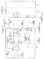
図3は、本実施形態に係るフィールドレコーダ101及びアダプタ102のブロック図である。
XLRレセプタクル215の2番ピン(ホット側ライン207)と3番ピン(コールド側ライン208)は、インピーダンス切替部301を通じてマイクアンプ302が接続される。また、ホット側ライン207とコールド側ライン208にはファンタム電源切替部303が接続されている。マイクアンプ302にはゲイン切替部304が設けられている。
一方、データ信号入力コネクタ214にはデータ受信部305が接続されており、データ受信部305には周知のマイコンよりなる制御部306が接続されている。FIG. 3 is a block diagram of the
The
On the other hand, a
制御部306は、XLRレセプタクル215に設けられている接続検出部307から接続検出信号を受けると、マイクロフォン201のデータ信号出力部211から送信されるマイク設定情報をデータ受信部305から受けて、ファンタム電源切替部303、インピーダンス切替部301及びゲイン切替部304を制御する。
また、制御部306は自動設定に非対応のマイクロフォン201の接続を受け入れて手動の設定を行うために、タイマ308と、操作部309と、表示部310が接続されている。
マイクアンプ302の出力信号は、フィールドレコーダ101内部のA/D変換器311を通じて記録部312に送られる。なお、モニタ等の信号経路は割愛する。When the
In addition, a
The output signal of the
図4は、ファンタム電源切替部303、インピーダンス切替部301及びゲイン切替部304の詳細を示す図である。
ファンタム電源切替部303は、ファンタム電源を供給する電圧源のラインに接続される電源供給スイッチ401と、電源供給スイッチ401とホット側ライン207とコールド側ライン208にそれぞれ接続される抵抗R402及びR403よりなる。制御部306が電源供給スイッチ401をオン・オフ制御することで、ファンタム電源電圧の、ホット側ライン207とコールド側ライン208への供給が制御される。FIG. 4 is a diagram illustrating details of the phantom
The phantom
インピーダンス切替部301は、ホット側ライン207に接続される抵抗R404及びR405と、この抵抗R404及びR405をオペアンプであるマイクアンプ302のプラス側入力端子に選択的に接続する切替スイッチ406と、コールド側ライン208に接続される抵抗R407及びR408と、この抵抗R407及びR408をマイクアンプ302のマイナス側入力端子に選択的に接続する切替スイッチ409よりなる。 The
切替スイッチ406及び切替スイッチ409は、制御部306によって連動して切替制御される。切替スイッチ406及び切替スイッチ409で抵抗R404及びR405と、抵抗R407及びR408を切り替えることで、マイクアンプ302の入力インピーダンスを変更する。 The
ゲイン切替部304は、マイクアンプ302のマイナス側入力端子に接続される抵抗R410及びR411と、この抵抗R410及びR411をマイクアンプ302の出力端子に選択的に接続する切替スイッチ412よりなる。切替スイッチ412で抵抗R410及びR411を切り替えることで、マイクアンプ302の帰還抵抗の値が切り替わり、ゲインが変更される。 The
図5は、アダプタ102に設けられているXLRレセプタクル215と接続検出部307の詳細を示す図である。
XLRレセプタクル215a及び215bには周縁の筒501a及び501bに切
り欠き502a、502b、502c及び502dが設けられており、この切り欠きを通過するように、発光ダイオード503と、反射板504と、フォトトランジスタ505a及び505bが設けられている。
XLRレセプタクル215aにXLRコネクタを差し込むと、切り欠き502a及び502bを通過している光がXLRコネクタによって遮られる。フォトトランジスタ505aは光が遮られたことでXLRコネクタの接続を検出する。
このXLRレセプタクル215は、特許文献1に開示されている。FIG. 5 is a diagram illustrating details of the
The
When the XLR connector is inserted into the XLR receptacle 215a, the light passing through the
This
図6は、制御部306が実行する、マイクロフォン201の自動設定の手順を示すフローチャートである。
フィールドレコーダ101が起動すると(S601)、制御部306は接続検出部307を確認して、XLRレセプタクル215にXLRコネクタが差し込まれたか、つまりマイクロフォン201が接続されたか否かを確認する(S602)。
マイクロフォン201の接続を確認したら(S602のYES)、制御部306は次にデータ受信部305を通じてデータの受信を開始すると共に、タイマ308を起動する(S603)。FIG. 6 is a flowchart showing a procedure for automatic setting of the microphone 201 executed by the
When the
When the connection of the microphone 201 is confirmed (YES in S602), the
これ以降はループ処理である。
制御部306は、先ずデータ受信部305がマイクロフォン201から送られた設定情報のデータを受信できたか否か、確認する(S604)。もし、受信できたのであれば(S604のYES)、後述する設定処理を実行して(S605)、その設定内容を表示部310に表示して(S606)、処理を終了する(S607)。Subsequent processing is loop processing.
First, the
ステップS604で設定情報のデータを受信できなかった場合は(S604のNO)、制御部306はタイマ308の値を確認して、予め定めた規定の時間に達したか、つまりタイムアウトになったか否かを確認する(S608)。タイムアウトの時間は例えば10秒である。タイムアウトになった場合(S608のYES)、制御部306は表示部310にエラーメッセージを表示して(S609)、予め定めた規定値を仮に設定した上で、操作部309による手動設定を可能にして(S610)、処理を終了する(S607)。 If the setting information data could not be received in step S604 (NO in S604), the
ステップS608でタイムアウトに至っていなければ(S608のNO)、制御部306は操作部309を確認して、使用者が割り込み操作を行っているか否かを確認する(S611)。これは、タイムアウトの10秒を待たずに手動設定を行いたい時に、操作部309の特定のキーを操作することで、即座に手動設定を実行するためである。割り込み操作が行われていれば(S611のYES)、操作部309による手動設定を可能にして(S610)、処理を終了する(S607)。割り込み操作が行われていなければ(S611のNO)、再度ステップS604に戻り、処理を継続する。 If the time-out has not been reached in step S608 (NO in S608), the
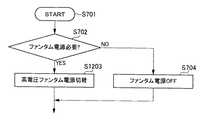
図7は、制御部306が実行する、設定処理の手順を示すフローチャートである。図6のステップS605の詳細である。
処理を開始すると(S701)、制御部306はデータ受信部305が受信したデータに基づいて、ファンタム電源が必要であるか否かを確認する(S702)。ファンタム電源が必要であれば(S702のYES)、制御部306はファンタム電源切替部303のスイッチをオン制御してファンタム電源をXLRケーブル206のホット側ライン207及びコールド側ライン208に印加する(S703)。ファンタム電源が不要であれば(S702のNO)、制御部306はファンタム電源切替部303のスイッチをオフ制御する(S704)。FIG. 7 is a flowchart illustrating the procedure of setting processing executed by the
When the process is started (S701), the
次に、制御部306はデータ受信部305が受信したデータに基づいて、マイクロフォン201のインピーダンスの値を確認する(S705)。本実施形態では簡略化のため、入力インピーダンスを低インピーダンスと高インピーダンスとに区別し、区別のための閾値として、例えば1kΩという値を予め定めているとする。
データ受信部305が受信したデータにはマイクロフォン201のインピーダンスが記述されており、制御部306はこのインピーダンス値を閾値と比較する。もし、インピーダンス値が閾値以上である場合なら(S705のYES)、制御部306は高いインピーダンスである第一インピーダンス値に、切替スイッチを切り替える(S706)。インピーダンス値が閾値未満である場合なら(S705のNO)、制御部306は低いインピーダンスである第二インピーダンス値に、切替スイッチを切り替える(S707)。Next, the
The data received by the
次に、制御部306はデータ受信部305が受信したデータに基づいて、マイクアンプ302のゲインの値を確認する(S708)。本実施形態では簡略化のため、ゲインを低ゲインと高ゲインとに区別し、区別のための閾値として、例えばマイクロフォン201の出力クリッピングレベルに−10dBVという値を予め定めているとする。
データ受信部305が受信したデータにはマイクロフォン201の出力クリッピングレベルが記述されており、制御部306はこの出力クリッピングレベルを閾値と比較する。もし、出力クリッピングレベルが閾値以上である場合なら(S708のYES)、制御部306は低いゲインである第一ゲイン値に、切替スイッチを切り替える(S709)。出力クリッピングレベルが閾値未満である場合なら(S708のNO)、制御部306は高いゲインである第二インピーダンス値に、切替スイッチを切り替える(S710)。
以上のステップを経て、制御部306は一連の処理を終了する(S711)。Next, the
The data received by the
Through the above steps, the
ステップS702、S703及びS704は、ファンタム電源のオン・オフの選択なので、基本的にこれ以上の選択はないが、ステップS705、S706及びS707に示すインピーダンスの設定と、ステップS708、S709及びS710に示すゲインの設定は、切替スイッチのタップ数及び抵抗の数を増やして、閾値を複数設定することで、3種類以上の値を選択することができる。 Steps S702, S703, and S704 are phantom power on / off selections, so there is basically no further selection, but impedance settings shown in steps S705, S706, and S707 and steps S708, S709, and S710 are shown. For the gain setting, three or more types of values can be selected by increasing the number of taps and the number of resistors of the changeover switch and setting a plurality of threshold values.
以上に説明した第一の実施形態に係るマイクロフォン201では、フィールドレコーダ101に接続されるアダプタ102に、周知の放送関連機器と同様にXLRケーブル206で接続する。それと共に、アダプタ102に設けられているデータ信号入力コネクタ214とマイクロフォン201に設けられているデータ信号出力コネクタ213とを専用のデータ転送ケーブル217で接続する。
データ信号出力部211は、アダプタ102内部のデータ受信部214との接続を検出すると、内蔵するROM212に書き込まれているマイクロフォン201のための設定情報をデータ信号に変換して、データ転送ケーブル217を通じてアダプタ102に送信する。
制御部306は、データ受信部214が受信したデータ信号の内容に基づいて、インピーダンス切替部301、ファンタム電源切替部303及びゲイン切替部304に適切な設定制御を実行する。すなわち、マイクロフォン201に適した自動設定が完遂する。In the microphone 201 according to the first embodiment described above, the
When the data
The
[第二の実施形態:信号線にデータ伝送を重畳する実施形態]
第一の実施形態では、マイクロフォン201の設定情報をフィールドレコーダ101等の機器に送信するために、専用のデータ伝送経路をマイクロフォン201とフィールドレコーダ101に設けた。これに対し、専用のデータ伝送経路を設けず、既存のXLRケーブル206をデータ伝送にも兼用することが考えられる。
図8は、本発明の第二の実施形態に係るコンデンサマイクロフォンのブロック図である。
図9は、本発明の第二の実施形態に係るフィールドレコーダ及びアダプタのブロック図である。
図8のコンデンサマイクロフォン801は、図9のフィールドレコーダ101にXLRケーブル206だけで接続される。[Second embodiment: Embodiment in which data transmission is superimposed on a signal line]
In the first embodiment, a dedicated data transmission path is provided in the microphone 201 and the
FIG. 8 is a block diagram of a condenser microphone according to the second embodiment of the present invention.
FIG. 9 is a block diagram of a field recorder and an adapter according to the second embodiment of the present invention.
The condenser microphone 801 in FIG. 8 is connected to the
図8の、コンデンサマイクロフォン801のブロック図について説明する。
XLRレセプタクル216に接続されるホット側ライン207とコールド側ライン208には、ファンタム電源を取り出すための抵抗R209及びR210が接続されている。この抵抗R209及びR210を通じてファンタム電源電圧が平衡アンプ203とコンデンサマイクユニット802に印加される。A block diagram of the condenser microphone 801 in FIG. 8 will be described.
Resistors R209 and R210 for extracting phantom power are connected to the
一方、ファンタム電源電圧は接続判定部ともいえる電圧判定部803にも供給される。電圧判定部803はファンタム電源電圧が規定の+48Vであるか、それとも低電圧(例えば+5V)であるか、判定する。もし、低電圧であった場合は、データ信号出力部211にデータ信号を出力させるべく制御する。 On the other hand, the phantom power supply voltage is also supplied to a
データ信号出力部211は、内蔵するROM212に格納されているデータに基づいて、所定の変調方式で変調した信号を生成する。この信号は平衡アンプ203の入力端子に印加されるので、平衡アンプ203を通じてXLRケーブル206を伝わり、接続される機器(本実施形態であれば図9に示すフィールドレコーダ101)に送信される。 The data signal
図9の、フィールドレコーダとアダプタのブロック図について説明する。但し、図3の、第一の実施形態のフィールドレコーダ101と同一のブロックについては説明を省略する。
図9のフィールドレコーダ901とアダプタ902の、図3のフィールドレコーダ101とアダプタ102との最大の相違点は、データ受信部305がマイクアンプ302の出力端子に接続されていることと、A/D変換器311に制御部306からミュートのための制御信号が供給されていることである。これ以外は、実質的な相違点はない。A block diagram of the field recorder and adapter in FIG. 9 will be described. However, the description of the same blocks as those of the
The greatest difference between the field recorder 901 and the adapter 902 in FIG. 9 between the
図10は、ファンタム電源切替部、インピーダンス切替部及びゲイン切替部の詳細を示す図である。但し、図4の、第一の実施形態のファンタム電源切替部903、インピーダンス切替部301及びゲイン切替部304と同一のブロックについては説明を省略する。
図10と図4の最大の相違点は、ファンタム電源切替部903が+48Vと0Vの他に+5Vを供給できるように、低電圧源ラインが追加され、電源供給スイッチ401が電源切替スイッチ1003になっている点である。これ以外の、インピーダンス切替部301及びゲイン切替部304は、図4のインピーダンス切替部301及びゲイン切替部304と相違点はない。FIG. 10 is a diagram illustrating details of the phantom power supply switching unit, the impedance switching unit, and the gain switching unit. However, the description of the same blocks as the phantom
The biggest difference between FIG. 10 and FIG. 4 is that a low voltage source line is added so that the phantom
図11は、制御部306が実行する、マイクロフォン201の自動設定の手順を示すフローチャートの一部である。図6に示したフローチャートのうち、異なる部分だけを抜粋して示している。すなわち、第二の実施形態のフィールドレコーダ101の制御部306は、図6のステップS603に代えて、図11に示すステップS1103を実行する。
フィールドレコーダ101が起動すると(S601)、制御部306は接続検出部307を確認して、XLRレセプタクル215にXLRコネクタが差し込まれたか、つまりマイクロフォン201が接続されたか否かを確認する(S602)。
マイクロフォン201の接続を確認したら(S602のYES)、制御部306は次にファンタム電源切替部303を制御して、低電圧(本実施形態では+5V)をホット側ライン207及びコールド側ライン208に印加して、データ受信部305を通じてデータの受信を開始すると共に、タイマ308を起動する(S1103)。FIG. 11 is a part of a flowchart showing a procedure for automatic setting of the microphone 201 executed by the
When the
When the connection of the microphone 201 is confirmed (YES in S602), the
図12は、制御部306が実行する、設定処理の手順を示すフローチャートの一部である。図7に示したフローチャートのうち、異なる部分だけを抜粋して示している。すなわち、第二の実施形態のフィールドレコーダ101の制御部306は、図7のステップS703に代えて、図12に示すステップS1103を実行する。 FIG. 12 is a part of a flowchart showing the procedure of setting processing executed by the
XLRケーブル206をデータ転送に兼用するには、マイクロフォン201の側でも機器との接続を検出する必要がある。そこで、本実施形態では機器側(フィールドレコーダ101)に二種類の異なる電圧のファンタム電源を供給可能に構成し、マイクロフォン201側はこの+5Vという低電圧が印加されたことを以って、自動設定対応機器が接続されたことを認識する。 In order to use the
本実施形態は以下の応用例が考えられる。
(1)第二の実施形態ではファンタム電源の電圧を二種類用意し、規定の電圧よりも低い電圧をマイクロフォン201に与えることで、マイクロフォン201側に自動設定対応機器である旨を伝えることを実現している。
自動設定対応機器である旨を伝える、ということは、マイクロフォン201と機器との間に双方向通信が実現されればよい、と考えることができる。そこで、ファンタム電源の電圧を変化させる代わりに、XLRケーブル206にモデムを接続して、双方向通信にてマイクロフォン201のデータを機器に送信することもできる。この場合、図11のステップS1103は、低電圧ファンタム電源を供給する代わりに、マイクロフォン201側に搭載されたモデムとのネゴシエーションのための信号を送信することとなる。また、アダプタ902ではモデムはホット側ライン207及びコールド側ライン208に接続することとなる。The following application examples can be considered for this embodiment.
(1) In the second embodiment, two types of phantom power supply voltages are prepared, and a voltage lower than a specified voltage is applied to the microphone 201, thereby realizing that the microphone 201 is informed of the automatic setting compatible device. is doing.
It can be considered that the fact that the device is an automatic setting compatible device only needs to realize bidirectional communication between the microphone 201 and the device. Therefore, instead of changing the voltage of the phantom power supply, a modem can be connected to the
(2)第一及び第二の実施形態では、フィールドレコーダを開示したが、本発明が適用される機器はこれに限られない。例えばオーディオミキサーにも適用できる。また、レコーディングスタジオやライブ会場等の施設の壁面等に設置される、ミキシングコンソールに接続されるXLRレセプタクルに、第一及び第二の実施形態に開示したアダプタを組み込むこともできる。 (2) In the first and second embodiments, the field recorder is disclosed, but the device to which the present invention is applied is not limited to this. For example, it can be applied to an audio mixer. Moreover, the adapter disclosed in the first and second embodiments can be incorporated into an XLR receptacle connected to a mixing console installed on a wall surface of a facility such as a recording studio or a live venue.
本実施形態ではマイクロフォン201及びオーディオ信号処理装置を開示した。
ファンタム電源のオン・オフ、最適な入力インピーダンスの選択、最適なマイクアンプ302のゲイン調整という、従来では煩雑なマイクロフォン201に関わる諸条件の設定作業が、第一の実施形態では専用のケーブルをマイクロフォン201とオーディオ信号処理装置との間に接続するだけで、第二の実施形態では従来と同様にXLRケーブル206をマイクロフォン201とオーディオ信号処理装置との間に接続するだけで、自動設定が完遂される。本実施形態により簡便且つ迅速に設定が完遂されるだけでなく、設定操作の誤りに起因する機器の破壊を防ぐこともできる。In the present embodiment, the microphone 201 and the audio signal processing device have been disclosed.
Setting of various conditions related to the conventional microphone 201 such as phantom power on / off, selection of optimum input impedance, and optimum gain adjustment of the
以上、本発明の実施形態例について説明したが、本発明は上記実施形態例に限定されるものではなく、特許請求の範囲に記載した本発明の要旨を逸脱しない限りにおいて、他の変形例、応用例を含む。 The embodiment of the present invention has been described above. However, the present invention is not limited to the above-described embodiment, and other modifications may be made without departing from the gist of the present invention described in the claims. Includes application examples.
101…フィールドレコーダ、102…アダプタ、103…XLRケーブルコネクタ、104…液晶ディスプレイ、105…操作ボタン、201…マイクロフォン、202…マイクユニット、203…平衡アンプ、206…XLRケーブル、207…ホット側ライン、208…コールド側ライン、211…データ信号出力部、212…ROM、213…データ信号出力コネクタ、214…データ信号入力コネクタ、215…XLRレセプタクル、215a…XLRレセプタクル、216…XLRレセプタクル、301…インピーダンス切替部、302…マイクアンプ、303…ファンタム電源切替部、304…ゲイン切替部、305…データ受信部、306…制御部、307…接続検出部、308…タイマ、309…操作部、310…表示部、311…A/D変換器、312…記録部、401…電源供給スイッチ、406…切替スイッチ、409…切替スイッチ、412…切替スイッチ、501a…筒、503…発光ダイオード、504…反射板、505a…フォトトランジスタ、801…コンデンサマイクロフォン、802…コンデンサマイクユニット、803…電圧判定部、901…フィールドレコーダ、902…アダプタ、903…ファンタム電源切替部、1003…電源切替スイッチ、C204…カップリングコンデンサ、R209…抵抗、R402…抵抗、R404…抵抗、R407…抵抗、R410…抵抗 DESCRIPTION OF
Claims (10)
Translated fromJapanese前記マイクユニットの信号を出力するコネクタと、
機器に接続されたことを検出すると、入力インピーダンス値及び入力ゲイン値に関する情報をデータ信号として生成するデータ信号出力部と
を具備するマイクロフォン。A microphone unit,
A connector for outputting a signal of the microphone unit;
A microphone including a data signal output unit that generates information about an input impedance value and an input gain value as a data signal when it is detected that the device is connected to the device.
前記データ信号出力部はファンタム電源の有無も検出する、
請求項1記載のマイクロフォン。The connector is balanced;
The data signal output unit also detects the presence or absence of phantom power,
The microphone according to claim 1.
前記データ信号を出力するデータ信号出力コネクタと
を具備する、請求項2記載のマイクロフォン。Furthermore,
The microphone according to claim 2, further comprising a data signal output connector that outputs the data signal.
前記平衡型コネクタに外部機器が接続されたことを検出する接続判定部と
を備え、
前記データ信号出力部は前記データ信号を前記平衡型コネクタを通じて前記外部機器に出力する、請求項2記載のマイクロフォン。Furthermore,
A connection determination unit that detects that an external device is connected to the balanced connector;
The microphone according to claim 2, wherein the data signal output unit outputs the data signal to the external device through the balanced connector.
前記マイクロフォンの信号を増幅するマイクアンプと、
所定の制御信号を受けて、前記平衡型コネクタの前記ホット側ラインと前記コールド側ラインにファンタム電源電圧を供給するファンタム電源切替部と、
前記平衡型コネクタの前記ホット側ラインと前記コールド側ラインと前記マイクアンプに接続され、所定の制御信号を受けて、前記マイクアンプの入力インピーダンスを切り替えるインピーダンス切替部と、
前記マイクアンプに接続され、所定の制御信号を受けて、前記マイクアンプのゲインを切り替えるゲイン切替部と、
ファンタム電源の有無、入力インピーダンス値及び入力ゲイン値に関する情報が含まれるデータ信号を受信するデータ受信部と、
前記データ受信部から得られる前記データ信号に基づいて、前記ファンタム電源切替部、前記インピーダンス切替部及び前記ゲイン切替部に制御信号を供給する制御部と
を具備するオーディオ信号処理装置。A balanced connector having a hot side line and a cold side line to which a microphone signal is input;
A microphone amplifier for amplifying the microphone signal;
A phantom power switching unit that receives a predetermined control signal and supplies a phantom power voltage to the hot-side line and the cold-side line of the balanced connector;
An impedance switching unit that is connected to the hot-side line, the cold-side line, and the microphone amplifier of the balanced connector, receives a predetermined control signal, and switches an input impedance of the microphone amplifier;
A gain switching unit that is connected to the microphone amplifier, receives a predetermined control signal, and switches the gain of the microphone amplifier;
A data receiver that receives a data signal including information on the presence or absence of a phantom power supply, an input impedance value, and an input gain value;
An audio signal processing apparatus comprising: a control unit that supplies a control signal to the phantom power switching unit, the impedance switching unit, and the gain switching unit based on the data signal obtained from the data receiving unit.
前記制御部に接続され、時間の経過を通知するタイマと、
前記制御部に接続され、前記ファンタム電源切替部、前記インピーダンス切替部及び前記ゲイン切替部に対する設定の内容を表示する表示部と、
前記制御部に接続され、前記制御部が前記タイマによって自動設定の待ち時間を経過したことを受けて、前記ファンタム電源切替部、前記インピーダンス切替部及び前記ゲイン切替部に対して手動にて設定を実行するための操作部と
を具備する、請求項7記載のオーディオ信号処理装置。Furthermore,
A timer connected to the control unit to notify the passage of time;
A display unit that is connected to the control unit and displays setting contents for the phantom power switching unit, the impedance switching unit, and the gain switching unit;
Connected to the control unit, and when the control unit has passed the automatic setting waiting time by the timer, the phantom power switching unit, the impedance switching unit, and the gain switching unit are manually set. The audio signal processing apparatus according to claim 7, further comprising an operation unit for executing the audio signal processing apparatus.
前記データ受信部が接続されて前記データ信号が入力されるデータ信号入力コネクタと
を具備する、請求項8記載のオーディオ信号処理装置。Furthermore,
The audio signal processing apparatus according to claim 8, further comprising a data signal input connector to which the data signal is input by being connected to the data receiving unit.
Priority Applications (1)
| Application Number | Priority Date | Filing Date | Title |
|---|---|---|---|
| JP2009256450AJP2011101318A (en) | 2009-11-09 | 2009-11-09 | Microphone and audio signal processing apparatus |
Applications Claiming Priority (1)
| Application Number | Priority Date | Filing Date | Title |
|---|---|---|---|
| JP2009256450AJP2011101318A (en) | 2009-11-09 | 2009-11-09 | Microphone and audio signal processing apparatus |
Publications (1)
| Publication Number | Publication Date |
|---|---|
| JP2011101318Atrue JP2011101318A (en) | 2011-05-19 |
Family
ID=44192113
Family Applications (1)
| Application Number | Title | Priority Date | Filing Date |
|---|---|---|---|
| JP2009256450APendingJP2011101318A (en) | 2009-11-09 | 2009-11-09 | Microphone and audio signal processing apparatus |
Country Status (1)
| Country | Link |
|---|---|
| JP (1) | JP2011101318A (en) |
Cited By (2)
| Publication number | Priority date | Publication date | Assignee | Title |
|---|---|---|---|---|
| JP2013034052A (en)* | 2011-08-01 | 2013-02-14 | Olympus Imaging Corp | Voice recording and reproducing system |
| EP3062533A1 (en)* | 2015-02-26 | 2016-08-31 | Kabushiki Kaisha Audio-Technica | Microphone connecting device |
- 2009
- 2009-11-09JPJP2009256450Apatent/JP2011101318A/enactivePending
Cited By (4)
| Publication number | Priority date | Publication date | Assignee | Title |
|---|---|---|---|---|
| JP2013034052A (en)* | 2011-08-01 | 2013-02-14 | Olympus Imaging Corp | Voice recording and reproducing system |
| US9131291B2 (en) | 2011-08-01 | 2015-09-08 | Olympus Corporation | Audio recording and playback device, and power feed method for audio recording and playback device |
| EP3062533A1 (en)* | 2015-02-26 | 2016-08-31 | Kabushiki Kaisha Audio-Technica | Microphone connecting device |
| US9774969B2 (en) | 2015-02-26 | 2017-09-26 | Kabushiki Kaisha Audio-Technica | Microphone connecting device |
Similar Documents
| Publication | Publication Date | Title |
|---|---|---|
| US7031476B1 (en) | Method and apparatus for intelligent speaker | |
| US8103009B2 (en) | Wired, wireless, infrared, and powerline audio entertainment systems | |
| US7346332B2 (en) | Wired, wireless, infrared, and powerline audio entertainment systems | |
| US7853341B2 (en) | Wired, wireless, infrared, and powerline audio entertainment systems | |
| US8811908B2 (en) | Method and apparatus for expanding wireless rear speaker in home theater system | |
| JP2010056684A (en) | Audio signal processing device, speaker device, video display device, and control method | |
| CA2320451A1 (en) | Transmission of power and/or signalling between an audio distribution unit and a plurality of remote audio transducers | |
| US8830040B2 (en) | Apparatus, systems and methods for power line carrier data communication to DC powered electronic device | |
| JP5036075B2 (en) | Wireless microphone transceiver | |
| JP2011101318A (en) | Microphone and audio signal processing apparatus | |
| CN102098472A (en) | Method for controlling audio output and digital device using the same | |
| US7236600B1 (en) | Transmission of power and/or signalling between an audio distribution unit and a plurality of remote audio transducers | |
| US8503890B2 (en) | Signal processing device and method, and infrared multi-channel receiver | |
| CN1855706B (en) | Music reproduction device for portable device | |
| EP1861934A1 (en) | Communication apparatus and communication method | |
| US20080101623A1 (en) | Device for Receiving Audio Signals Transmitted in a Wireless Manner | |
| KR100195114B1 (en) | Apparatus for controlling line attenuation of data | |
| JP2010252155A (en) | High-frequency apparatus and community reception system provided with the same | |
| JP5266968B2 (en) | Audio signal processing device, speaker device, video display device, communication device, and audio system | |
| JP2009111471A (en) | Coupler, and communication coupling method | |
| KR970004631B1 (en) | Car stereo system control apparatus for compact disk player | |
| JP6512958B2 (en) | Communication system, communication apparatus, and communication method | |
| KR101148188B1 (en) | Surveillance system | |
| KR20150041828A (en) | Power Line Communication Speaker System | |
| JP2008258889A (en) | Content communication apparatus |