JP2011097431A - Arm-mounted electronic apparatus - Google Patents
Arm-mounted electronic apparatusDownload PDFInfo
- Publication number
- JP2011097431A JP2011097431AJP2009250631AJP2009250631AJP2011097431AJP 2011097431 AJP2011097431 AJP 2011097431AJP 2009250631 AJP2009250631 AJP 2009250631AJP 2009250631 AJP2009250631 AJP 2009250631AJP 2011097431 AJP2011097431 AJP 2011097431A
- Authority
- JP
- Japan
- Prior art keywords
- antenna
- electronic device
- dial
- back cover
- arm
- Prior art date
- Legal status (The legal status is an assumption and is not a legal conclusion. Google has not performed a legal analysis and makes no representation as to the accuracy of the status listed.)
- Pending
Links
- 238000000034methodMethods0.000claimsabstractdescription9
- 230000008569processEffects0.000claimsabstractdescription8
- 239000000758substrateSubstances0.000claimsdescription32
- 230000002093peripheral effectEffects0.000claimsdescription18
- 239000000463materialSubstances0.000description17
- 239000006059cover glassSubstances0.000description16
- 239000004973liquid crystal related substanceSubstances0.000description16
- 229910052751metalInorganic materials0.000description14
- 239000002184metalSubstances0.000description14
- 230000008878couplingEffects0.000description12
- 238000010168coupling processMethods0.000description12
- 238000005859coupling reactionMethods0.000description12
- 230000000694effectsEffects0.000description9
- 239000012811non-conductive materialSubstances0.000description5
- 229920003002synthetic resinPolymers0.000description5
- 239000000057synthetic resinSubstances0.000description5
- 239000000919ceramicSubstances0.000description4
- 238000004891communicationMethods0.000description4
- 210000004247handAnatomy0.000description4
- 230000007246mechanismEffects0.000description3
- 238000004904shorteningMethods0.000description3
- 239000010935stainless steelSubstances0.000description3
- 229910001220stainless steelInorganic materials0.000description3
- RYGMFSIKBFXOCR-UHFFFAOYSA-NCopperChemical compound[Cu]RYGMFSIKBFXOCR-UHFFFAOYSA-N0.000description2
- 230000000903blocking effectEffects0.000description2
- 230000008859changeEffects0.000description2
- 229910052802copperInorganic materials0.000description2
- 239000010949copperSubstances0.000description2
- 238000010586diagramMethods0.000description2
- 239000007769metal materialSubstances0.000description2
- 230000004048modificationEffects0.000description2
- 238000012986modificationMethods0.000description2
- 230000005855radiationEffects0.000description2
- 229910052709silverInorganic materials0.000description2
- 239000004332silverSubstances0.000description2
- 238000004088simulationMethods0.000description2
- 210000000707wristAnatomy0.000description2
- 229910001369BrassInorganic materials0.000description1
- 229910001069Ti alloyInorganic materials0.000description1
- 239000000853adhesiveSubstances0.000description1
- 230000001070adhesive effectEffects0.000description1
- 239000002390adhesive tapeSubstances0.000description1
- PNEYBMLMFCGWSK-UHFFFAOYSA-Naluminium oxideInorganic materials[O-2].[O-2].[O-2].[Al+3].[Al+3]PNEYBMLMFCGWSK-UHFFFAOYSA-N0.000description1
- 239000010951brassSubstances0.000description1
- 230000009194climbingEffects0.000description1
- 230000006866deteriorationEffects0.000description1
- 229910003460diamondInorganic materials0.000description1
- 239000010432diamondSubstances0.000description1
- 239000003989dielectric materialSubstances0.000description1
- 239000000284extractSubstances0.000description1
- 239000011521glassSubstances0.000description1
- WABPQHHGFIMREM-UHFFFAOYSA-Nlead(0)Chemical compound[Pb]WABPQHHGFIMREM-UHFFFAOYSA-N0.000description1
- 239000010445micaSubstances0.000description1
- 229910052618mica groupInorganic materials0.000description1
- 230000010355oscillationEffects0.000description1
- 239000003973paintSubstances0.000description1
- 238000007747platingMethods0.000description1
- 230000003068static effectEffects0.000description1
- 230000000007visual effectEffects0.000description1
Images


Classifications
- H—ELECTRICITY
- H01—ELECTRIC ELEMENTS
- H01Q—ANTENNAS, i.e. RADIO AERIALS
- H01Q1/00—Details of, or arrangements associated with, antennas
- H01Q1/27—Adaptation for use in or on movable bodies
- H01Q1/273—Adaptation for carrying or wearing by persons or animals
- G—PHYSICS
- G04—HOROLOGY
- G04G—ELECTRONIC TIME-PIECES
- G04G5/00—Setting, i.e. correcting or changing, the time-indication
- G04G5/002—Setting, i.e. correcting or changing, the time-indication brought into action by radio
- G—PHYSICS
- G04—HOROLOGY
- G04R—RADIO-CONTROLLED TIME-PIECES
- G04R60/00—Constructional details
- G04R60/06—Antennas attached to or integrated in clock or watch bodies
- G04R60/10—Antennas attached to or integrated in clock or watch bodies inside cases
- H—ELECTRICITY
- H01—ELECTRIC ELEMENTS
- H01Q—ANTENNAS, i.e. RADIO AERIALS
- H01Q1/00—Details of, or arrangements associated with, antennas
- H01Q1/40—Radiating elements coated with or embedded in protective material
- H—ELECTRICITY
- H01—ELECTRIC ELEMENTS
- H01Q—ANTENNAS, i.e. RADIO AERIALS
- H01Q7/00—Loop antennas with a substantially uniform current distribution around the loop and having a directional radiation pattern in a plane perpendicular to the plane of the loop
Landscapes
- Physics & Mathematics (AREA)
- General Physics & Mathematics (AREA)
- Electric Clocks (AREA)
- Support Of Aerials (AREA)
- Aerials With Secondary Devices (AREA)
- Details Of Aerials (AREA)
Abstract
Translated fromJapaneseDescription
Translated fromJapanese本発明は、外部から送信される時刻情報等を含む無線電波を受信可能なアンテナを内蔵する腕装着型電子機器に関する。 The present invention relates to an arm-mounted electronic device including an antenna capable of receiving radio waves including time information transmitted from the outside.
近年、無線通信機能を備えた電子時計が開発されている。このような無線通信機能としては、例えばGPS(Global Positioning System)等、位置情報衛星からの電波を受けて現在時刻を取得する機能が利用される。
このような無線機能付きの電子時計として、例えば腕時計に無線機能を付与する場合、限られたスペースで良好な機能を確保できるアンテナが要求される(例えば、特許文献1,2参照)。In recent years, electronic watches having a wireless communication function have been developed. As such a wireless communication function, for example, a function of acquiring the current time by receiving radio waves from a position information satellite such as GPS (Global Positioning System) is used.
As such an electronic timepiece with a wireless function, for example, when a wireless function is given to a wristwatch, an antenna that can ensure a good function in a limited space is required (for example, see Patent Documents 1 and 2).
特許文献1では、表示部の周囲に誘電体基板を伴うC型ループアンテナを配置するとともに、腕時計の金属製本体ベースをグランド板として利用している。
特許文献2では、不平衡給電されるアンテナを腕時計のカバーガラスとムーブメントとの間に配置された文字板の外周に沿って配置するとともに、文字板をグランド板の一部として利用している。In Patent Document 1, a C-type loop antenna with a dielectric substrate is arranged around a display unit, and a metal main body base of a wristwatch is used as a ground plate.
In
しかしながら、前述した特許文献1および特許文献2の構成は、十分なアンテナ性能を確保できないという問題がある。すなわち、特許文献1,2では、アンテナとグランド板(金属製本体ベースや文字板)との距離が近く、グランド板による無線電波の良好な反射が得られにくく、十分なアンテナ性能が得られないという問題がある。 However, the configurations of Patent Document 1 and
本発明の主な目的は、良好な受信性能を確保できる腕装着型電子機器を提供することである。 A main object of the present invention is to provide an arm-mounted electronic device that can ensure good reception performance.
本発明の腕装着型電子機器は、外部から送信される無線電波を受信するアンテナと、少なくとも一部が非導電性部材にて形成されたケースと、このケース内に収納され、非導電性部材にて板状に形成された情報表示部と、前記ケースに取り付けられ、導電性部材にて形成される裏蓋と、前記ケース内の前記情報表示部および前記裏蓋間に位置して収納され、前記アンテナで受信した無線電波に基づく受信信号を処理する受信部と、を備え、前記アンテナは、前記情報表示部の周囲に沿って配置されて線状に形成されたアンテナ電極を有し、前記裏蓋は、前記受信部のグランド電位に接続されて前記無線電波を反射する反射板として機能することを特徴とする。 An arm-mounted electronic device according to the present invention includes an antenna that receives radio waves transmitted from the outside, a case that is at least partially formed of a non-conductive member, and a non-conductive member that is housed in the case. And an information display unit formed in a plate shape, a back cover attached to the case and formed of a conductive member, and positioned between the information display unit and the back cover in the case. A reception unit that processes a reception signal based on a radio wave received by the antenna, and the antenna has an antenna electrode that is arranged along the periphery of the information display unit and formed in a linear shape, The back cover is connected to a ground potential of the receiving unit and functions as a reflecting plate that reflects the radio wave.
ここで、前記アンテナ電極とは、周方向で連続する環状のアンテナ電極の他、周方向で不連続となる環状の一部が欠けた例えばC字形状のアンテナ電極をも含むものである。
また、腕装着型とは、手首に装着する場合のみならず、例えば上腕に装着するなど、腕のいずれの位置に装着するものも対象とすることができる。
本発明では、アンテナで受信した無線電波に基づく受信信号を処理する受信部を情報表示部および裏蓋間に配置させ、情報表示部の周囲に沿って線状のアンテナ電極を配置させるとともに、裏蓋を導電性部材にて形成して無線電波を反射する反射板として機能させている。このことにより、情報表示部と裏蓋とは、間に受信部が介在するためにある程度の距離で離間する。このため、情報表示部の周囲に沿って配置されたアンテナ電極と裏蓋(反射板)もある程度の距離で離間する状態となり、アンテナに近接する文字板等を反射板とした場合に比べて、アンテナでの受信性能を向上できる。さらに、裏蓋が反射板として機能するので、腕時計として利用してもアンテナ同調周波数の変化を防止でき、アンテナの特性を向上でき、良好な受信特性が得られる。特に、裏蓋は、比較的に外形寸法を大きく設計しやすいため、無線電波の反射効率の向上が容易で、アンテナの特性を容易に向上できる。Here, the antenna electrode includes, for example, a C-shaped antenna electrode lacking a part of an annular shape that is discontinuous in the circumferential direction, in addition to an annular antenna electrode that is continuous in the circumferential direction.
In addition, the arm-mounted type can be applied not only to the case of wearing on the wrist, but also to the type of wearing on any position of the arm such as wearing on the upper arm.
In the present invention, a receiving unit that processes a received signal based on radio waves received by an antenna is disposed between the information display unit and the back cover, and a linear antenna electrode is disposed along the periphery of the information display unit. The lid is formed of a conductive member and functions as a reflector that reflects radio waves. Thus, the information display unit and the back cover are separated by a certain distance because the receiving unit is interposed therebetween. For this reason, the antenna electrode and the back cover (reflecting plate) arranged along the periphery of the information display unit are also separated by a certain distance, compared to a case where a dial plate close to the antenna is used as a reflecting plate, The reception performance with the antenna can be improved. Furthermore, since the back cover functions as a reflecting plate, even if it is used as a wristwatch, a change in the antenna tuning frequency can be prevented, the antenna characteristics can be improved, and good reception characteristics can be obtained. In particular, since the back cover can be designed with a relatively large outer dimension, it is easy to improve the reflection efficiency of radio waves, and the characteristics of the antenna can be easily improved.
本発明の腕装着型電子機器において、前記裏蓋は、前記アンテナ電極の外形寸法より大きい外形寸法に形成されていることが好ましい。 In the arm-mounted electronic device according to the aspect of the invention, it is preferable that the back cover is formed with an outer dimension larger than the outer dimension of the antenna electrode.
この発明では、アンテナ電極の外形寸法より大きい裏蓋にて無線電波をより効率よく反射してアンテナ電極に入る受信強度を向上できる。 According to the present invention, it is possible to improve the reception intensity entering the antenna electrode by reflecting the radio wave more efficiently with the back cover larger than the outer dimension of the antenna electrode.
本発明の腕装着型電子機器において、前記情報表示部の周囲に沿って配置され、非導電性部材にて環状に形成されたダイヤルリングと、このダイヤルリングの外周側に配置され、非導電性部材にて環状に形成されたベゼルとを備え、前記アンテナは、前記ダイヤルリングと前記ベゼルとの間に覆われて配置されていることが好ましい。 In the wrist-worn electronic device of the present invention, a dial ring that is disposed along the periphery of the information display unit and formed in a ring shape with a non-conductive member, and is disposed on the outer peripheral side of the dial ring, and is non-conductive It is preferable that a bezel formed in an annular shape by a member is provided, and the antenna is disposed so as to be covered between the dial ring and the bezel.
このように、本発明では、非導電性部材にて環状に形成されたダイヤルリングとベゼルとの間にアンテナを配置しているため、無線電波が遮断されることなく、良好な受信性能が得られるとともに、アンテナがダイヤルリングおよびベゼルで覆われて外部に露出することがないため、外観が損なわれることも防止できる。 As described above, in the present invention, since the antenna is disposed between the dial ring and the bezel formed in a ring shape by the non-conductive member, the radio wave is not blocked and good reception performance is obtained. In addition, since the antenna is covered with the dial ring and the bezel and is not exposed to the outside, the appearance can be prevented from being damaged.
本発明の腕装着型電子機器において、前記アンテナは、前記アンテナ電極が設けられる環状の誘電体基材を有し、前記アンテナ電極は、前記誘電体基材により波長短縮された前記無線電波の波長に対して略1波長分の周囲長に形成されていることが好ましい。 In the arm-mounted electronic device of the present invention, the antenna has an annular dielectric substrate on which the antenna electrode is provided, and the antenna electrode has a wavelength of the radio wave shortened by the dielectric substrate. On the other hand, it is preferably formed to have a peripheral length of approximately one wavelength.
ここで、環状の誘電体基材としては、周方向で連続する形状、例えば平面円形や平面矩形状のものに限らず、周方向の一部が欠けた周方向で不連続の例えば平面C字形状の誘電体基材をも含むものである。
本発明では、アンテナとして、誘電体基材に設けるアンテナ電極の周囲長を、誘電体基材により波長短縮された無線電波の波長に対して略1波長としているので、アンテナの受信性能を最適にできる。
なお、周囲長が波長短縮された波長に対して略1波長とは、例えば、0.9波長〜1.3波長の範囲、特に1.1波長が好適である。Here, the annular dielectric base material is not limited to a shape that is continuous in the circumferential direction, for example, a planar circular shape or a planar rectangular shape, but is, for example, a planar C shape that is discontinuous in the circumferential direction with a part of the circumferential direction missing. It also includes a shaped dielectric substrate.
In the present invention, as the antenna, the perimeter of the antenna electrode provided on the dielectric substrate is set to approximately one wavelength with respect to the wavelength of the radio wave shortened by the dielectric substrate, so that the antenna reception performance is optimized. it can.
For example, approximately one wavelength with respect to the wavelength whose peripheral length is shortened is preferably in the range of 0.9 wavelength to 1.3 wavelength, particularly 1.1 wavelength.
本発明の腕装着型電子機器において、前記アンテナは、前記アンテナ電極が設けられる環状の誘電体基材を有し、前記アンテナ電極は、前記誘電性基材における前記裏蓋に対向する下面とは反対側の上面に配置される環状のアンテナ本体部と、このアンテナ本体部の一部に設けられる少なくとも1つ以上の分岐点から分岐され、前記誘電性基材に設けられる給電部と、を有し、前記ケース内に収納され、前記給電部に接触するとともに前記受信信号を前記受信部に伝達する接続部材を備えていることが好ましい。 In the arm-mounted electronic device according to the aspect of the invention, the antenna includes an annular dielectric substrate on which the antenna electrode is provided, and the antenna electrode is a lower surface facing the back cover of the dielectric substrate. A ring-shaped antenna main body disposed on the upper surface on the opposite side; and a power feeding unit that is branched from at least one branch point provided in a part of the antenna main body and is provided on the dielectric substrate. In addition, it is preferable to include a connection member that is housed in the case, contacts the power feeding unit, and transmits the received signal to the receiving unit.
ここで、環状の誘電体基材やアンテナ本体部としては、周方向で連続する形状、例えば平面円形や平面矩形状のものに限らず、周方向の一部が欠けた周方向で不連続の例えば平面C字形状の誘電体基材やアンテナ本体部をも含むものである。また、誘電体基材やアンテナ本体部は、両方とも周方向で連続する形状の場合と、両方とも周方向で不連続の形状の場合と、一方が周方向で連続する形状であり、他方が周方向で不連続の形状である場合のいずれでもよい。
この発明では、誘電体基材の上面側に配置されたアンテナ本体部で受信した電波の受信信号は、アンテナ本体部から分岐された給電部から接続部材を介して受信部に伝達される。このことから、例えば接続部材が他の導電性の部位と接触しないように接続部材を貫通させる貫通部を設けるなどの簡単な構成で、受信した電波に基づく受信信号が適切に受信部へ伝達される。Here, the annular dielectric substrate and the antenna main body are not limited to a shape that is continuous in the circumferential direction, for example, a planar circular shape or a planar rectangular shape, but are discontinuous in the circumferential direction in which a part of the circumferential direction is missing. For example, it includes a planar C-shaped dielectric substrate and an antenna main body. In addition, the dielectric base material and the antenna main body are both continuous in the circumferential direction, both discontinuous in the circumferential direction, and one continuous in the circumferential direction. Any of the shapes discontinuous in the circumferential direction may be used.
In this invention, the received signal of the radio wave received by the antenna main body disposed on the upper surface side of the dielectric base material is transmitted from the power feeding unit branched from the antenna main body to the receiving unit via the connecting member. For this reason, for example, a reception signal based on the received radio wave is appropriately transmitted to the reception unit with a simple configuration such as providing a through portion that penetrates the connection member so that the connection member does not come into contact with other conductive parts. The
本発明の腕装着型電子機器において、前記情報表示部は、文字板または表示パネルであることが好ましい。 In the wrist-worn electronic device of the present invention, it is preferable that the information display unit is a dial or a display panel.
本発明では、非導電性部材で形成された情報表示部として、文字板または表示パネルを用いる。ここで、非導電性部材にて形成される文字板とは、文字板の周囲に沿ってアンテナ電極を配置した際に、所定の受信特性を確保できるものであればよく、例えば、プラスチックやセラミックスなどの非導電性部材で形成された文字板が利用できる。また、非導電性部材にて形成される表示パネルとは、表示パネルの周囲に沿ってアンテナ電極を配置した際に、所定の受信特性を確保できるものであればよく、液晶パネルや有機EL(Electro Luminescence)パネル、電気泳動型表示パネルなど、一部に導電性の部品を備えていても、アンテナでの受信特性上は非導電性部材と見なせる表示パネルが利用できる。
このような非導電性部材で形成された文字板や表示パネルの周囲に沿ってアンテナ電極を配置すれば、受信特性の劣化がなく、良好な受信特性が得られる。In the present invention, a dial or a display panel is used as the information display unit formed of a non-conductive member. Here, the dial plate formed of a non-conductive member may be any plate that can ensure predetermined reception characteristics when the antenna electrode is disposed along the periphery of the dial plate. A dial plate formed of a non-conductive member such as can be used. In addition, the display panel formed of a non-conductive member may be any display panel that can ensure predetermined reception characteristics when an antenna electrode is disposed along the periphery of the display panel. A display panel that can be regarded as a non-conductive member in terms of reception characteristics of the antenna can be used even if a part of the electro-luminescent display panel or the electrophoretic display panel is provided with conductive parts.
If the antenna electrodes are arranged along the periphery of the dial plate or display panel formed of such a non-conductive member, the reception characteristics are not deteriorated and good reception characteristics can be obtained.
[第1実施形態]
以下、本発明に係る第1実施形態を図面に基づいて説明する。[First Embodiment]
DESCRIPTION OF EXEMPLARY EMBODIMENTS Hereinafter, a first embodiment according to the invention will be described with reference to the drawings.
図1に示すように、電子機器1は、腕に装着されるもので、情報表示部としての文字板2及び指針3を備えた時刻表示用の時刻表示部を備える腕装着型の電子時計である。
文字板2は、非導電性部材、例えば合成樹脂やより高級な質感が得られるセラミックスなどにて円板状に形成されている。そして、文字板2の一部には開口が形成され、情報表示部としてのLCD(Liquid Crystal Display)パネル等からなるディスプレイ4が組み込まれている。
指針3は、秒針、分針、時針等を備えて構成され、後述するステップモーター及び歯車列を含む駆動機構を介して駆動される。なお、指針3は面積が小さいことから、金属製であっても無線電波の受信に支障ないが、非導電性材料であれば無線電波が遮断される影響を回避できて好ましい。
ディスプレイ4はLCDパネル等で構成され、緯度、経度や都市名等の位置情報を表示する他、メッセージ情報を表示する。As shown in FIG. 1, an electronic device 1 is worn on an arm, and is an arm-mounted electronic timepiece having a time display unit for time display including a
The
The
The display 4 is composed of an LCD panel and the like, and displays message information as well as position information such as latitude, longitude, and city name.
そして、電子機器1は、地球の上空を所定の軌道で周回している複数のGPS衛星5a,5b,5c,5dなどからの衛星信号を受信して衛星時刻情報を取得し、内部時刻情報を修正できるように構成されている。
なお、図1に示すGPS衛星5a,5b,5c,5dは、本発明における位置情報衛星の一例であり、地球の上空に複数存在している。現在は約30個のGPS衛星5a,5b,5c,5dが周回している。
また、電子機器1には、外部操作用のリュウズ6、ボタン7,8が設けられている。The electronic device 1 receives satellite signals from a plurality of
Note that the
Further, the electronic device 1 is provided with a
<電子機器1の内部構成>
次に、電子機器1の内部構成について説明する。
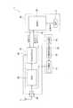
図2及び図3に示すように、電子機器1は、指針3を駆動するモジュール110と、モジュール110を収容する本体ケース10とを備えている。<Internal configuration of electronic device 1>
Next, the internal configuration of the electronic device 1 will be described.
As shown in FIGS. 2 and 3, the electronic device 1 includes a
本体ケース10は、円筒状の外装ケース101を備えている。この外装ケース101の一方の開口(図2下側)には、開口を塞ぐ円板状の裏蓋102が設けられている。
外装ケース101は、非導電性部材である各種合成樹脂で形成されている。この外装ケース101により、本発明のケースが構成されている。The
The
また、裏蓋102には、BS(真鍮)、SUS(ステンレス鋼)、チタン合金などの導電性部材の金属材料が利用される。そして、裏蓋102は、後述するモジュール110の接地端子105に接続している。接地端子105は、モジュール110の受信部18のグランド電位に接続している。このため、裏蓋102は、接地端子105を介して受信部18のグランド電位に電気的に接続しており、カバーガラス130側から入射する電波をGPSアンテナ11に向かって反射させる、いわゆるグランド板(反射板)として機能する。
裏蓋102は外装ケース101の一方の開口(図2下側)に対してねじ構造により接続される。これにより、本体ケース10内には、外装ケース101の他方の開口(図2上側)に開口面103を有するキャビティー104が形成され、このキャビティー104にモジュール110が収容される。The
The
さらに、外装ケース101の開口面103が形成される端面には、文字板2が配設されている。
そして、文字板2の外周縁の一部、具体的には、電子機器1の9時位置近傍には、カバーガラス130側の空間とモジュール110側の空間を連通する切欠部121が形成されている。Further, the
A
モジュール110は、前述した指針3による時刻表示を行うとともに、図1に示すGPS衛星5a,5b,5c,5dからの信号受信を行うためのものである。そして、モジュール110は、時刻表示及びGPS機能を処理する回路素子(ICなど)が実装された回路基板25(図4参照)、指針3を駆動するステップモーター及び歯車列を含む図示しない駆動機構、これらに電力を供給する二次電池91(図5参照)などを備えている。
なお、回路基板25に実装された回路素子としては、GPS衛星5a,5b,5c,5dから受信した信号を処理する受信部18(図4参照)や、駆動機構の制御を行う制御部20(図4参照)などが含まれている。そして、回路素子のうち、受信部18は、ノイズの影響を避けるために、GPSアンテナ11、LCDパネルに対して回路基板25の反対側(裏蓋102側)で、かつ回路基板25の中央部に設けられる。The
The circuit elements mounted on the
電子機器1は、図2及び図3に示すように、文字板2の外周に沿って配置されたリング状のGPSアンテナ11を備えている。
GPSアンテナ11は、前述したGPS衛星5a,5b,5c,5dからの信号を受信するものであり、文字板2の表面側に配置され、文字板2の外周縁と、GPSアンテナ11の外周縁とが略一致する状態に形成されている。そして、GPSアンテナ11の最大寸法である外径寸法(外形寸法)は、裏蓋102の外径寸法(外形寸法)より小さい寸法に形成されている。すなわち、裏蓋102の外径の方が、GPSアンテナ11より大きく形成されている。なお、このGPSアンテナ11の詳細については後述する。As shown in FIGS. 2 and 3, the electronic device 1 includes a ring-shaped
The
電子機器1は、GPSアンテナ11を収容するダイヤルリング140を備えている。
ダイヤルリング140は、非導電性部材である合成樹脂にて円環状に形成され、外周にGPSアンテナ11を収容する凹みを有する。ダイヤルリング140は、文字板2の表面側(電子機器1の厚さ方向におけるカバーガラス130側)で、文字板2の周囲に沿って配置され、内周が文字板2へと向かう傾斜面(円錐面)とされ、この傾斜面には60分割で指示目盛が印刷されている。The electronic device 1 includes a
ダイヤルリング140の外周にはベゼル150が配置され、ベゼル150の内側には、文字板2の表面側及び指針3を覆うカバーガラス130が配置されている。
ベゼル150は、外周が外装ケース101の外周に連続する円環状に形成され、互いの対向面に形成された凹凸による嵌め合わせ構造あるいは両面粘着テープや接着剤等の手段により本体ケース10の外装ケース101に接続されている。ベゼル150は、カバーガラス130を保持するとともに、ダイヤルリング140を文字板2側へ押しつけて保持している。
そして、ダイヤルリング140の凹みに配置されたGPSアンテナ11は、ダイヤルリング140とベゼル150とで覆われる状態に配置されている。
以上により、カバーガラス130がモジュール110の表面側を覆うように配置され、カバーガラス130とモジュール110との間に文字板2が配置され、この文字板2とカバーガラス130との間に指針3及びGPSアンテナ11が配置されている。A
The
The
Thus, the
電子機器1において、本体ケース10の裏蓋102は、質感の優れた導電性部材である金属材料で形成されている。
外装ケース101、文字板2、ダイヤルリング140及びベゼル150は、非導電性材料で形成され、カバーガラス130も非導電性のガラス質材料で形成されている。これらの各要素は質感を考慮した表面仕上げが施されている。なお、ベゼル150を構成する非導電性材料としては、例えば合成樹脂を用いることも可能であるが、より硬度が高くて傷が付きにくく、より高級な質感が得られるセラミックスにより形成されることが好ましい。
このような材質とすることで、文字板2から表面側(図2上側)にあるダイヤルリング140,ベゼル150、カバーガラス130は全て非導電性材料となり、これらがGPSアンテナ11に対して電磁気的な遮蔽物として影響することはない。In the electronic device 1, the
The
By using such a material, the
<GPSアンテナの詳細>
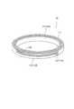
GPSアンテナ11は、図4に示すように、矩形断面形状を有するリング状の誘電体基材111を備え、その表面にアンテナ電極112が形成されている。このGPSアンテナ11が本発明のアンテナを構成し、アンテナ電極112が本発明のアンテナ部を構成している。<Details of GPS antenna>
As shown in FIG. 4, the
誘電体基材111は、電波の波長を短縮させる機能を有する。すなわち、GPS衛星5a,5b,5c,5dから送信される衛星信号は、周波数が1.575GHz、波長が19cmである円偏波である。このような衛星信号の電波をループアンテナで受信するためには、バランを必要としない不平衡給電されるループアンテナとグランド板(反射板)との距離を、0.10波長〜0.25波長程度に設定することが好ましい。この距離より狭くなると、イメージアンテナの影響により、受信特性が劣化する可能性がある。
この周波数が1.575GHzの衛星信号の電波を、誘電体を用いずに受信させるためには、ループアンテナとグランド板との間隔を3〜4.8cmとする必要があり、腕時計としては適用できない寸法となる。これに対して、誘電体基材111上にアンテナ電極112を設置することで、誘電体基材111により衛星信号の電波の波長を短縮させ、短縮させた波長をアンテナ電極112で受信させることが可能となる。ここで、比誘電率εrの誘電体基材111では、電波の波長短縮率は1/(εr)1/2となる。このため、比誘電率εrの値を大きくすれば、より波長短縮されることとなる。
一方、比誘電率εrの高い誘電体を用いると周波数帯域幅が狭くなり急峻な特性となり周波数調整が困難となったり、腕に装着した場合に周波数ズレで特性が劣化してしまうおそれがある。
したがって、実際に利用できる誘電体としては、比誘電率εrが20以下、好ましくは4〜10に設定された誘電体基材111である。このような誘電体基材111としては、例えばアルミナ(εr=8.5)を主成分としたセラミックや、マイカを成分としたセラミックである、いわゆるマイカレックス(εr=6.5〜9.5)、ガラス(εr=5.4〜9.9)、ダイヤモンド(εr=5.68)などを用いることができる。
このような誘電体基材111を用いることで、波長19cmの衛星信号の電波を、例えば直径約3cm(周囲長約9.4cm)(比誘電率εrが5の場合)のループアンテナ型のアンテナ電極112にて受信させることができ、一般的な時計ケース内にGPSアンテナ11を配置できる。
また、誘電体基材111を用いることで、ループアンテナとグランド板との適切な間隔は0.8〜2.0cm程度となる。一般的な腕時計の厚さ寸法は、0.8〜1.6cmであることから、誘電体基材111を用いることで、ループアンテナとグランド板とを適切な間隔に設定しても、十分に腕時計として適用できる。The
In order to receive a satellite signal radio wave having a frequency of 1.575 GHz without using a dielectric, the distance between the loop antenna and the ground plate needs to be 3 to 4.8 cm, which is not applicable as a wristwatch. It becomes a dimension. On the other hand, by installing the
On the other hand, the ratio may become With dielectric constant epsilonr of high dielectric difficult frequency adjustment becomes steep characteristic frequency bandwidth is narrowed, there is a possibility that the characteristics in the frequency deviation deteriorates when worn on the wrist .
Therefore, a dielectric material that can be actually used is the
By using such a
In addition, by using the
アンテナ電極112は、誘電体基材111の表面に、銅や銀などの導電性の金属素子を印刷したり、銀や銅などの導電性の金属板を誘電体基材111の表面に貼り付けたりすることで、誘電体基材111に線状に一体的に形成される。なお、誘電体基材111の表面にパターン形成してもよい。
このアンテナ電極112は、アンテナ本体部113と、結合部114と、給電部115と、を備えている。
アンテナ本体部113は、誘電体基材111の裏蓋102に対向する下面とは反対側の上面側にリング状に形成される線状部分であり、カバーガラス130側から進入した電波、または裏蓋102により反射された電波を受信する。このアンテナ本体部113は、周囲長が受信する電波を誘電体基材111により波長短縮された波長に対する略1波長(0.9波長〜1.3波長)の長さに形成されている。特に、アンテナ本体部113の周囲長は、1.1波長の長さが最適である。具体的には、誘電体基材111の比誘電率εrが20である場合には、アンテナ本体部113の直径は約3cmとなる。
そして、このアンテナ本体部113の内周縁の一部には、分岐点116が形成され、この分岐点116から誘電体基材111の内周側面に延出して結合部114が形成される。この結合部114は、誘電体基材111の内周側面に沿って周方向に形成される。そして、結合部114の分岐点116とは反対側の端部は、誘電体基材111の下面側に向かって延出し、誘電体基材111の下面側において、結合部114に連続する給電部115が形成される。この給電部115は、図2及び図3に示すように、電子機器1の9時方向で、文字板2の切欠部121に対向する位置に形成され、切欠部121を挿通する接続ピン61の先端部が給電部115の一点(給電点117)に接触する。ここで、分岐点116から結合部114を通り給電点117に至るまでの長さ寸法は、GPSアンテナ11で受信する電波の約1/4波長の長さ寸法である。The
The
The antenna
A
給電部115の給電点117に接する接続部材としての接続ピン61は、電子機器1の9時方向に立設される接続基部62に出没自在に保持されている。このように、接続ピン61を9時方向に設けることで、3時方向に設けられる外部操作用のリュウズ6や、2時、4時方向に設けられるボタン7,8等との構造的な干渉を避けることができる。また、接続ピン61および接続基部62は、電気的に接続されており、接続基部62は、回路基板25の受信部18に接続される。そして、この接続基部62は、略円筒状に形成されるとともに、その筒内部に例えばコイルばねなどの付勢部材が設けられており、接続ピン61を給電部115側に付勢している。これにより、接続ピン61は、給電点117に押圧され、例えば電子機器1に衝撃が加わった際でも、接続ピン61と給電点117との接続状態が維持される。
また、接続基部62は、図4に示すように、リード線251により回路基板25の中央部の接続点251Aに接続され、この接続点251Aにおいて、回路基板25の裏蓋102側に設けられる受信部18に接続されている。ここで、本実施形態のような1波長ループアンテナのGPSアンテナ11により効率的な円偏波受信のために、接続点251Aは、回路基板25の中央部に位置することが好ましい。一方で、接続点251Aを回路基板25の中央部に設ける場合、配線が長くなるため、信号損失が増大するという問題がある。このような問題を改善するために、GPSアンテナ11および受信部18の間、より具体的には、GPSアンテナ11と、1.5GHzの衛星信号を抜き出す図示しないバンドパスフィルターとの間に、後述するLNA(ローノイズアンプ)28(図5参照)を設け、信号損失を補う構成としてもよい。
なお、接続基部62と受信部18との接続方法としては、上記に限られず、例えば接続基部62が回路基板25上のプリント配線に接続され、プリント配線を介して受信部18に接続される構成などとしてもよい。
また、本発明のGPSアンテナ11としては、合成樹脂製のダイヤルリング140の上側表面に金属メッキを施してアンテナ電極112を形成するなどして、ダイヤルリング140に一体化されたGPSアンテナ11を用いてもよい。この場合も、アンテナ電極112が形成されるダイヤルリング140の上側表面をベゼル150で被覆することで、アンテナ電極112が外部に露出せず、外観を向上できる。A
Further, as shown in FIG. 4, the
The connection method between the
Further, as the
本実施形態において、導電性部材製の裏蓋102はグランド板を兼ねるものであり、GPSアンテナ11のグランド板としての機能を有する。この裏蓋102は、外径がGPSアンテナ11の外径より大きく形成されている。そして、GPSアンテナ11は、アンテナ電極112が平面的、すなわち電子機器1の厚さ方向で裏蓋102に重なる状態となっている。 In this embodiment, the
さらに、裏蓋102が金属製なので、グランド板として機能する他に、装着するユーザーの腕によるGPSアンテナ11への影響を回避できる。
ここで、図6は、GPSアンテナ11の放射パターンのシミュレーション結果を示す特性図である。図6に示すように、GPSアンテナ11のカバーガラス130側となる天頂方向をZ軸とし、このZ軸に対する傾きを角度θとする。なお、GPSアンテナ11の裏蓋102側は、角度θが180°である。
この図6に示すように、裏蓋102がプラスチックケースだと、グランド板がない状態となり、裏蓋102側である腕側からも電波を受信できる状態となる。このため、近傍にある腕の影響を受けて装着時と非装着時でアンテナの共振周波数が変動し、性能差が出て好ましくない。一方、本実施形態では、裏蓋102が金属製なので、裏蓋102がグランド板(反射板)として機能して、電子機器1の上方向である角度θが0°近傍でのアンテナゲインが向上している。さらに、裏蓋102が金属製なので、そのシールド効果により下方側である角度θが180°近傍でのアンテナゲインが小さい。このことから、上述した腕の影響を回避でき、本実施形態では装着時と非装着時とのアンテナ特性差が殆どなく、安定した受信性能が得られる。Furthermore, since the
Here, FIG. 6 is a characteristic diagram showing a simulation result of the radiation pattern of the
As shown in FIG. 6, when the
[電子機器1の回路構成]
次に、電子機器1の回路構成に関して説明する。
図5は、電子機器1の主なハードウエア構成等を示す概略図である。
図5に示すように、電子機器1は、GPSアンテナ11、信号増幅手段であるLNA(ローノイズアンプ)28、受信部18、時刻表示装置80及び電源供給装置90を含んで構成されている。[Circuit Configuration of Electronic Device 1]
Next, the circuit configuration of the electronic device 1 will be described.
FIG. 5 is a schematic diagram illustrating a main hardware configuration and the like of the electronic device 1.
As shown in FIG. 5, the electronic device 1 includes a
GPSアンテナ11は、複数のGPS衛星5a,5b,5c,5dからの衛星信号を受信するループアンテナである。
このGPSアンテナ11の出力は、LNA28に接続されている。The
The output of the
LNA28は、GPSアンテナ11で受信した衛星信号が入力される。また、LNA28の出力は、受信部18に接続されている。 The satellite signal received by the
受信部18は、主にRF(Radio Frequency:無線周波数)部50と、GPS信号処理部60を含んで構成されている。RF部50とGPS信号処理部60とは、1.5GHz帯の衛星信号から航法メッセージに含まれる軌道情報やGPS時刻情報等の衛星情報を取得する処理を行う。
なお、本実施形態の受信部18は、例えば8個の衛星信号を同時に捕捉、受信できるように8チャンネルの受信回路を備えている。The receiving
Note that the receiving
RF部50は、高周波信号を中間周波数帯の信号に変換するダウンコンバーターや、その中間周波数帯のアナログ信号をデジタル信号に変換するA/Dコンバーターなどを備えたGPS受信機における一般的なものである。 The
GPS信号処理部60は、図示を略すがDSP(Digital Signal Processor)、CPU(Central Processing Unit)、SRAM(Static Random Access Memory)、RTC(リアルタイムクロック)等を含んで構成され、RF部50から出力されるデジタル信号(中間周波数帯の信号)からベースバンド信号を復調する処理を行う。 Although not shown, the GPS
また、GPS信号処理部60は、衛星信号検索結果に基づいて前記LNA28の図示しない制御信号入力端子に制御信号を出力してLNA28の作動を制御する。
具体的には、捕捉した衛星信号の信号強度が予め設定された閾値未満の場合、LNA28を作動状態に制御する。
一方、捕捉した衛星信号の信号強度が予め設定された閾値以上の場合、LNA28を停止状態に制御する。
さらに、GPS信号処理部60は、受信モードに応じて、受信部18の動作を制御する。Further, the GPS
Specifically, when the signal strength of the captured satellite signal is less than a preset threshold value, the
On the other hand, when the signal strength of the captured satellite signal is equal to or higher than a preset threshold value, the
Furthermore, the GPS
時刻表示装置80は、制御部20と、指針3を備えて構成されている。
制御部20は、受信部18を制御する。すなわち、制御部20は、ボタン7,8が押し続けられて強制受信操作が行われた場合や、予め受信時刻が設定されておりその時刻になった場合に、制御信号を受信部18に送り、受信部18の受信動作を制御する。また、制御部20内の図示しない駆動回路を介して指針3の駆動を制御する。The
The
また、制御部20には、内部時刻情報が記憶されている。内部時刻情報は、電子機器1の内部で計時される時刻の情報である。内部時刻情報は、発振回路などによって生成される基準クロック信号によって更新される。したがって、受信部18への電力供給が停止されていても、内部時刻情報を更新して指針3の運針を継続することができるようになっている。
さらに、制御部20は、測時モードに設定されると、受信部18の動作を制御してGPS時刻情報を取得し、そのGPS時刻情報に基づいて内部時刻情報を修正して記憶する。より具体的には、内部時刻情報は、取得したGPS時刻情報に1980年1月6日以降挿入されたうるう秒の累積(現在は15秒)を減算することで求められるUTC(協定世界時)に修正される。さらに、時差データが記憶されている場合には、その時差データも加算して現在地の時刻情報に修正して記憶する。
また、制御部20は、測位モードに設定されると、受信部18の動作を制御してGPS時刻情報と測位データを取得し、そのGPS時刻情報とうるう秒の累積及び現在地から求められる時差データに基づいて、内部時刻情報を修正して記憶する。なお、測位データと時差データとの対応関係を表すデータは、予め記憶されている。The
Further, when the timekeeping mode is set, the
When the positioning unit is set to the positioning mode, the
電源供給装置90は、二次電池91、充電制御回路92および充電器93を含んで構成されている。
二次電池91は、LNA28、受信部18及び時刻表示装置80等に駆動電力を供給する。
充電器93は、例えば外装ケース101内に回転自在に配置された図示しない回転錘と、この回転錘の回転により発電する発電機とを備えている。なお、充電器93としては、発電機を備えた内部構成に限らず、例えば電子機器1とは別体構成で、外装ケース101内に配置した外部端子にて電力を供給する構成としてもよい。そして、外部端子としては、接触型もしくは非接触型のいずれの構成としてもよい。
充電制御回路92は、充電器93から供給される電力を二次電池に供給して充電させる。The
The
The
The
[受信処理]
次に、受信処理について説明する。
GPSアンテナ11で複数のGPS衛星5a,5b,5c,5dからの衛星信号を受信し、LNA28へ受信した衛星信号を出力する。
LNA28は、GPS信号処理部60からの制御信号に基づいて、受信した衛星信号を適宜増幅して受信部18へ出力する。具体的には、LNA28では、GPS信号処理部60から、オン信号(例えばハイレベル信号)が入力されると衛星信号をオペアンプなどで増幅して受信部18へ出力し、オフ信号(例えばローレベル信号)が入力されると、入力された衛星信号は増幅されずに受信部18へ出力する。[Receive processing]
Next, the reception process will be described.
The
The
受信部18のRF部50は、LNA28から出力された高周波の衛星信号を中間周波数帯の信号に変換するとともに、アナログ信号をデジタル信号に変換する。
受信部18のGPS信号処理部60は、各C/Aコードと同一のパターンのローカルコードを発生し、ベースバンド信号に含まれる各C/Aコードとローカルコードの相関をとる処理を行う。そして、GPS信号処理部60は、各ローカルコードに対する相関値がピークになるようにローカルコードの発生タイミングを調整し、相関値が閾値以上となる場合にはそのローカルコードのGPS衛星5a,5b,5c,5dに同期(すなわち、GPS衛星5a,5b,5c,5dを捕捉)したものと判断する。
ここで、GPSシステムでは、すべてのGPS衛星5a,5b,5c,5dが異なるC/Aコードを用いて同一周波数の衛星信号を送信するCDMA(Code Division Multiple Access)方式を採用している。従って、受信した衛星信号に含まれるC/Aコードを判別することで、捕捉可能なGPS衛星5a,5b,5c,5dを検索することができる。
また、GPS信号処理部60は、捕捉したGPS衛星5a,5b,5c,5dのC/Aコードと同一のパターンのローカルコードとベースバンド信号をミキシングして航法メッセージを復調し、航法メッセージに含まれる軌道情報やGPS時刻情報等の衛星情報を取得する。
そして、GPS信号処理部60は、取得した時刻データ、測位データを時刻表示装置80の制御部20に出力する。
そして、時刻表示装置80の制御部20は、GPS信号処理部60からの時刻データ、測位データに基づいて、内部時刻情報を修正して記憶し、適宜指針3を運針して表示時刻を修正する。The
The GPS
Here, the GPS system employs a CDMA (Code Division Multiple Access) system in which all
Further, the GPS
Then, the GPS
Then, the
[第1実施形態の作用効果]
上述したように、上記第1実施形態の電子機器1によれば、以下の効果がある。
(1)本実施形態では、裏蓋102として無線電波を反射させる導電性部材にて形成し、文字板2の周囲に沿って、GPSアンテナ11の線状のアンテナ電極112を配置している。
このことにより、GPSアンテナ11と裏蓋102とを、良好な受信性能が得られる距離に離間する状態が得られ、GPSアンテナ11での受信性能を向上できる。
さらに、裏蓋102が反射板として機能し、かつ腕時計として利用してもアンテナ同調周波数の変化を防止でき、GPSアンテナ11の特性を向上でき、良好な受信特性が得られる。
特に、電子機器1の厚さ寸法の方向において、文字板2よりカバーガラス130側の上方であり、文字板2より裏蓋102から遠くなる位置に配置されるダイヤルリング140およびベゼル150間にGPSアンテナ11を配置している。
このため、腕時計として利用しても、電子機器1の厚みを厚くすることなく、GPSアンテナ11と裏蓋102とを適切に離間させることができ、良好な受信性能が得られる。[Effects of First Embodiment]
As described above, the electronic device 1 according to the first embodiment has the following effects.
(1) In this embodiment, the
As a result, a state in which the
Furthermore, even if the
In particular, in the direction of the thickness dimension of the electronic device 1, the GPS is positioned between the
For this reason, even when used as a wristwatch, the
(2)GPSアンテナ11の外形寸法より導電性部材の裏蓋102を大きく形成している。
このため、裏蓋102の無線電波の反射効率が向上し、受信性能を向上できる。
特に、裏蓋102は、文字板2に比べて外形寸法を大きく設計できるため、無線電波の反射効率の向上が容易で、GPSアンテナ11の特性を容易に向上できる。(2) The
For this reason, the radio wave reflection efficiency of the
In particular, since the
(3)非導電性部材にて環状に形成されたダイヤルリング140とベゼル150との間にGPSアンテナ11を配置し、GPSアンテナ11をダイヤルリング140およびベゼル150で覆っている。
このため、無線電波が遮断されることがなく、良好な受信性能が得られる。
さらに、GPSアンテナ11が外部に露出することがなく、外観が損なわれることも防止できる。また、文字板2の周囲に配置されるダイヤルリング140とベゼル150との間にGPSアンテナ11を配置していることから、文字板2の表示視認を妨げることを防止できる。(3) The
For this reason, the radio wave is not blocked and good reception performance can be obtained.
Further, the
(4)GPSアンテナ11として、誘電体基材111に設けるループアンテナのアンテナ電極112の周囲長を、誘電体基材111により波長短縮された無線電波の波長に対して略1波長としているので、アンテナ性能を最適にできる。(4) As the
(5)非導電性部材にて形成させる情報表示部として文字板2を用いている。
例えば、導電性の文字板2を用いた場合では、文字板2がグランド板として機能し、GPSアンテナ11とグラウンド板となる文字板2とが隣接する状態となり、受信特性の劣化を生じるおそれがある。
本実施形態では、文字板2を非導電性部材にて構成しているので、文字板2はグラウンド板として機能することはなく、適性に離間する金属製の裏蓋102をグランド板として機能させることができ、無線電波を良好に受信できる。(5) The
For example, when the
In the present embodiment, since the
(6)GPSアンテナ11のアンテナ電極112は、リング状の誘電体基材111の上面に配置されるリング状のアンテナ本体部113と、アンテナ本体部113の内周縁の一点である分岐点から誘電体基材111の周面に沿う結合部114と、結合部114の分岐点116とは反対側の他端に連続し、誘電体基材111の下面側に形成される給電部115とにより形成される。そして、文字板2は、この給電部115に対向する位置に切欠部121が設けられ、この切欠部121を挿通して、モジュール110側から給電点117に向かって付勢される接続ピン61が設けられている。
このため、給電部115と文字板2との接触、接続ピン61と文字板2との接触を防止することができ、かつ接続ピン61によりアンテナ電極112と回路基板25の受信部18とを確実に電気的に接続することができる。また、接続ピン61が給電点117側に付勢されているため、例えば時計に衝撃が加わった場合でも接続ピン61と給電点117との接続が良好に維持することができる。(6) The
For this reason, the contact between the
[第2実施形態]
次に、本発明の第2実施形態を図面に基づいて説明する。
この第2実施形態は、第1実施形態における文字板2を用いて時刻表示する構成に代え、液晶表示により時刻表示するものである。
図7は、本発明の第2実施形態に係る電子機器1の概略断面図である。なお、以下の実施形態における図の説明にあたって、上記第1実施形態と同一構成要素については、同一符号を付し、その説明を省略する。[Second Embodiment]
Next, 2nd Embodiment of this invention is described based on drawing.
In the second embodiment, the time is displayed using a liquid crystal display instead of the time display using the
FIG. 7 is a schematic cross-sectional view of the electronic apparatus 1 according to the second embodiment of the present invention. In the description of the drawings in the following embodiments, the same components as those in the first embodiment are denoted by the same reference numerals, and the description thereof is omitted.
第2実施形態での本体ケース10は、非導電性部材製の円筒状の外装ケース101と、この外装ケース101の一方の開口(図7下側)を閉塞する導電性部材製の裏蓋102とを備えている。
外装ケース101には、板状の時刻表示用の情報表示部としての表示パネルである液晶パネル17を備え、液晶パネル17を制御するモジュール110が収容されている。なお、外装ケース101は、第1実施形態のダイヤルリング140およびベゼル150を備えていない。
モジュール110は、液晶パネル17の表示面17Aをカバーガラス130に向けて保持する液晶保持部110Aと、液晶パネル17と電気的に接続させる接続コネクター110Bとを備えている。
ここで、液晶パネル17は、微視的に透明電極などの導電性部材を有しているが、全体からの比率としては極めて少ないので、無線電波を遮断してしまう不都合はなく、実質的に非導電性部材として扱える。
そして、GPSアンテナ11は、モジュール110の外周に沿って液晶保持部110Aの外側に配設されている。すなわち、液晶パネル17の外周側に配置されている。A
The
The
Here, the
The
この図7に示す第2実施形態によれば、情報表示する構成として液晶パネル17を用いる点で、文字板2を用いる第1実施形態と異なるものの、前記第1実施形態の効果(1)〜(4),(6)を奏する他、以下の効果を奏する。 According to the second embodiment shown in FIG. 7, although the
(7)非導電性部材にて形成させる情報表示部として液晶パネル17を用いている。
このため、液晶パネル17にて無線電波が遮断されずにグランド板として機能する裏蓋102で反射させることができ、無線電波の反射効率を向上させ、GPSアンテナ11で無線電波を良好に受信できる。(7) The
Therefore, the radio wave can be reflected by the
(8)液晶パネル17の外周側に位置してGPSアンテナ11を配置している。
このため、電子機器1の厚さ寸法が厚くなることを防止できるとともに、GPSアンテナ11の径寸法を大きく設定できることから、受信性能を向上できる。(8) The
For this reason, while being able to prevent the thickness dimension of the electronic device 1 from becoming thick, since the diameter dimension of the
[第3実施形態]
次に、本発明の第3実施形態を図面に基づいて説明する。
この第3実施形態は、第1実施形態の非導電性部材製の外装ケース101に代えて、導電性部材製のカバー体101Aを用いたものである。
図8は、本発明の第3実施形態に係る電子機器1の概略分解斜視図である。[Third Embodiment]
Next, 3rd Embodiment of this invention is described based on drawing.
In the third embodiment, a
FIG. 8 is a schematic exploded perspective view of the electronic apparatus 1 according to the third embodiment of the present invention.
第3実施形態での本体ケース10は、一部が非導電性部材製の外装ケース101を備えている。この外装ケース101は、導電性部材製(ステンレスなどの金属製)のカバー体101Aと、このカバー体101Aの内周側に配置された非導電性部材製のケース体(胴)101Bと、を備えている。ケース体101Bの表面は、金属調の塗装を施すことで、金属製のカバー体101Aと質感を合わせている。 The
外装ケース101の一方の開口、具体的にはケース体101Bの軸方向の一端側(図8下側)には、導電性部材製の裏蓋102が設けられている。外装ケース101の表面側となる他方の開口、具体的にはカバー体101Aの開口(図8上側)には、カバーガラス130及びGPSアンテナ11を内蔵するベゼル部15が配置されている。このベゼル部15は、例えば第1実施形態におけるダイヤルリング140およびベゼル150にて構成されている。
なお、ベゼル部15は、ケース体101Bの軸方向の一端側(図8上側)に載置される状態に配置されている。すなわち、第1実施形態ではモジュール110の外周縁にGPSアンテナ11の外周縁が略一致する構成としているが、第3実施形態ではGPSアンテナ11の外径をモジュール110の外径より大きく形成している。A
In addition, the
また、カバー体101Aには、外部操作用のボタン7,8に対応して、ボタン用切欠部108が設けられている。さらに、カバー体101Aには、バンド106を取り付けるかん107の間のかんまた107Aの裏蓋102側縁が切り欠かれた切欠部109が設けられている。そして、カバー体101Aと裏蓋102とは、非接触状態であり、導通していないので、カバー体101Aがグランド板(反射板)として機能することはない。 The
この図8に示す第3実施形態によれば、導電性部材製のカバー体101Aおよび非導電性部材製のケース体101Bを備えた外装ケース101を用いる点で、上述した第1実施形態の非導電性部材の外装ケース101を用いる点と異なるものの、第1実施形態の効果(1)〜(6)を奏する他、以下の効果を奏する。 According to the third embodiment shown in FIG. 8, the
(9)外装ケース101として、金属製のカバー体101Aを備えているので、外装ケース101の外観の質感を向上できる。
さらに、カバー体101Aに、ボタン用切欠部108および切欠部109を設けている。このため、金属製のカバー体101Aが設けられていても、ボタン用切欠部108および切欠部109を介して無線電波を受信できるので、無線電波の受信性能の低下を最小限に抑えることができる。(9) Since the
Further, a
[実施形態の変形例]
なお、本発明は前述の実施形態に限定されるものではなく、本発明の目的を達成できる範囲での変形、改良等は本発明に含まれるものである。[Modification of Embodiment]
It should be noted that the present invention is not limited to the above-described embodiments, and modifications, improvements, and the like within the scope that can achieve the object of the present invention are included in the present invention.
前記実施形態では、GPSアンテナ11として、アンテナ本体部113の分岐点116から誘電体基材111の内周面に沿って結合部114が形成される例を示したが、これに限定されない。
例えば、図9に示すGPSアンテナ11のように、アンテナ本体部113の外周側に分岐点116が設けられ、この分岐点116から誘電体基材111の外周側面に延出し、外周側面の周方向に沿って結合部114が形成される構成などとしてもよい。In the said embodiment, although the example which forms the coupling |
For example, like the
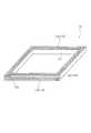
さらに、上記各実施形態において、円筒状のGPSアンテナ11を用いて説明したが、円筒形状に限られるものではない。
例えば、デジタル表示式の時計などにおいて、平面略方形状の外形形状を有する時計の場合には、図10に示すような、時計形状に合わせて正方形や長方形などの方形状のGPSアンテナ11を用いることもできる。
このような方形状のGPSアンテナ11では、平面方形状の時計にリング状のGPSアンテナ11を組み込む場合に比べて、アンテナ電極112の周囲長をより長く形成することができるため、よりアンテナ特性を良好にすることができる。また、平面方形状の時計では、方形状のGPSアンテナ11を用いることで、その内部空間を有効に活用でき、例えばデジタル表示用のディスプレイを大きく形成することができる。Furthermore, in each said embodiment, although demonstrated using the
For example, in a digital display timepiece or the like, in the case of a timepiece having a substantially rectangular external shape, a
In such a
また、GPSアンテナ11として、リング状のアンテナ本体部113を有する、いわゆるループアンテナを例示したが、これに限定されず、例えば図11に示すように、アンテナ本体部113はC字状形状に形成されるなどしてもよい。
この図11に示すGPSアンテナ11Aの場合でも、C字状のアンテナ本体部113Aの一端部から、1/4波長となる位置に結合部114に接続される分岐点116を形成することで、円偏波の電波が受信可能となる。Further, as the
Even in the case of the
また、上記各実施形態において、単一の給電部115が形成されるGPSアンテナ11を例示したが、複数の給電部115が形成されるGPSアンテナ11としてもよい。複数の給電部115を有するGPSアンテナ11として、いわゆる直交2点給電、つまり2箇所の給電部115を位相差が90度となる位置にそれぞれ配置するとよい。このようなGPSアンテナ11では、2つの給電部115に対して接続ピン61も2つ設けられ、これらの2つの接続ピン61から衛星信号が回路基板25に伝達される。また、回路基板25は、これら2つの経路の位相調整を実施して、受信部18に信号を伝達することで、円偏波の受信処理を実施する。
さらに、誘電体基材111の側面に結合部114を設ける構成に限らず、例えば誘電体基材111に軸方向に沿って貫通する穴を通してアンテナ本体部113と給電部115とを接続する構成としてもよい。Moreover, in each said embodiment, although the
Furthermore, not only the structure which provides the coupling |
また、給電部115に接触する接続部材として、接続ピン61を例示したが、このようなピン部材に限定されない。例えば、接続部材として、板ばね状に形成される接続板を用いてもよく、このような構成でも、板ばねの付勢力により接続板が給電点117に所定の接触圧で接続させることができる。 Moreover, although the
また、上述の第1ないし第3実施形態は、位置情報衛星の例としてGPS衛星5a,5b,5c,5dについて説明したが、本発明の位置情報衛星としては、GPS衛星5a,5b,5c,5dだけではなく、ガリレオ(EU)、GLONASS(ロシア)、北斗(中国)などの他の全地球的航法衛星システム(GNSS)や、SBASなどの静止衛星や準天頂衛星などの時刻情報を含む衛星信号を発信する位置情報衛星でもよい。
そして、本発明の腕装着型電子機器では、このような位置情報衛星から衛星信号を電波受信する構成に限られるものではなく、例えば900MHz帯を用いる円偏波の無線タグの近距離無線受信装置(900MHz帯のRF-ID機能)として適用することもできる。
さらには、本発明の腕装着型電子機器は、円偏波を受信する構成に限らず、直線偏波の電波を受信するものとしても用いることができる。
その他、無線電波としては、2.4GHz帯の無線通信を行うBluetooth(登録商標)、無線LANなども対象とすることができる。In the first to third embodiments described above, the
The wrist-worn electronic device according to the present invention is not limited to such a configuration that receives a satellite signal from a position information satellite. For example, a short-range wireless receiving device for a circularly polarized wireless tag using a 900 MHz band It can also be applied as (900 MHz band RF-ID function).
Furthermore, the wrist-worn electronic device of the present invention is not limited to a configuration that receives circularly polarized waves, but can also be used for receiving linearly polarized radio waves.
In addition, as the radio wave, Bluetooth (registered trademark) that performs radio communication in the 2.4 GHz band, a wireless LAN, and the like can be targeted.
また、本発明の腕装着型電子機器としては、腕時計に限らず、無線電波を受信または送信あるいは送受信する腕装着型の各種電子機器を対象とすることができる。
例えば、無線通信回線を利用する腕装着型の携帯電話機、現在位置から目的地まで案内誘導するナビゲーション装置、ランニング用や登山用など、移動距離や移動時間、通過場所や通過時間などを記録、表示する情報装置、通行証や入場証などのICカード機能およびICカード機能における利用状況の履歴等の情報を表示させる機能を備えた各種携帯情報端末などが例示できる。In addition, the wrist-worn electronic device of the present invention is not limited to a wristwatch, and can be a variety of arm-worn electronic devices that receive, transmit, or transmit / receive radio waves.
For example, record and display the travel distance, travel time, passing location, transit time, etc., such as wrist-mounted mobile phone using wireless communication line, navigation device that guides and guides from the current position to the destination, for running and climbing Examples of such information devices and various portable information terminals having a function of displaying information such as an IC card function such as a pass and entrance card and a history of usage status in the IC card function.
前述した第1および第3実施形態では、GPSアンテナ11を覆うリング部材としてダイヤルリング140を設けたが、これに限らず、リング部材は目盛のない部材であってもよく、内側面が傾斜面ではなく文字板2に対して垂直な面あるいは他の形状であるとしてもよい。また、リング部材は本発明に必須ではなく、例えばベゼル150の内周が内側に張り出してGPSアンテナ11を覆い隠せるようであれば、別体のリング部材は省略することができる。
さらに、GPSアンテナ11を文字板2や液晶パネル17等の表示パネルの下面側(裏蓋102側)に配置し、GPSアンテナ11を情報表示部で被覆してもよい。すなわち、本発明では、GPSアンテナ11のアンテナ電極112は、文字板2や表示パネル等の情報表示部の周囲に沿って配置されていればよい。従って、第1実施形態のように、情報表示部の上面側にアンテナ電極112が配置されていてもよいし、第2実施形態のように、情報表示部の外側にアンテナ電極112が配置されていてもよいし、情報表示部の下面側にアンテナ電極112が配置されていてもよい。In the first and third embodiments described above, the
Further, the
1…電子機器(腕装着型電子機器)、2…文字板(情報表示部)、11…GPSアンテナ(アンテナとしてのループアンテナ)、11A…GPSアンテナ(アンテナ)、17…液晶パネル(情報表示部としての表示パネル)、18…受信部、61…接続ピン(接続部材)101…外装ケース(ケース)、102…裏蓋、112…アンテナ電極、113…アンテナ本体部、115…給電部、116…分岐点、140…ダイヤルリング、150…ベゼル DESCRIPTION OF SYMBOLS 1 ... Electronic device (arm mounting type electronic device), 2 ... Dial (information display part), 11 ... GPS antenna (loop antenna as an antenna), 11A ... GPS antenna (antenna), 17 ... Liquid crystal panel (information display part) As a display panel), 18: receiving unit, 61: connecting pin (connecting member) 101 ... exterior case (case), 102 ... back cover, 112 ... antenna electrode, 113 ... antenna body, 115 ... feeding unit, 116 ... Branch point, 140 ... Dial ring, 150 ... Bezel
Claims (6)
Translated fromJapanese少なくとも一部が非導電性部材にて形成されたケースと、
このケース内に収納され、非導電性部材にて板状に形成された情報表示部と、
前記ケースに取り付けられ、導電性部材にて形成される裏蓋と、
前記ケース内の前記情報表示部および前記裏蓋間に位置して収納され、前記アンテナで受信した無線電波に基づく受信信号を処理する受信部と、を備え、
前記アンテナは、前記情報表示部の周囲に沿って配置されて線状に形成されたアンテナ電極を有し、
前記裏蓋は、前記受信部のグランド電位に接続されて前記無線電波を反射する反射板として機能する
ことを特徴とする腕装着型電子機器。An antenna for receiving radio waves transmitted from the outside;
A case in which at least a part is formed of a non-conductive member;
An information display unit housed in this case and formed in a plate shape with a non-conductive member,
A back cover attached to the case and formed of a conductive member;
A reception unit that is housed between the information display unit and the back cover in the case and that processes a reception signal based on a radio wave received by the antenna;
The antenna has an antenna electrode that is arranged along the periphery of the information display unit and formed in a linear shape,
The back cover functions as a reflector that is connected to the ground potential of the receiver and reflects the radio wave. The wrist-worn electronic device.
前記裏蓋は、前記アンテナ電極の外形寸法より大きい外形寸法に形成されている
ことを特徴とする腕装着型電子機器。The arm-mounted electronic device according to claim 1,
The back cover is formed in an outer dimension larger than the outer dimension of the antenna electrode.
前記情報表示部の周囲に沿って配置され、非導電性部材にて環状に形成されたダイヤルリングと、
このダイヤルリングの外周側に配置され、非導電性部材にて環状に形成されたベゼルとを備え、
前記アンテナは、前記ダイヤルリングと前記ベゼルとの間に覆われて配置されている
ことを特徴とする腕装着型電子機器。The arm-mounted electronic device according to claim 1 or 2,
A dial ring that is arranged along the periphery of the information display unit and formed in a ring shape with a non-conductive member;
It is arranged on the outer peripheral side of this dial ring, and comprises a bezel formed in a ring shape with a non-conductive member,
The arm-mounted electronic device, wherein the antenna is covered and disposed between the dial ring and the bezel.
前記アンテナは、前記アンテナ電極が設けられる環状の誘電体基材を有し、
前記アンテナ電極は、前記誘電体基材により波長短縮された前記無線電波の波長に対して略1波長分の周囲長に形成されている
ことを特徴とする腕装着型電子機器。In the arm mounting type electronic device according to any one of claims 1 to 3,
The antenna has an annular dielectric substrate on which the antenna electrode is provided,
The arm-mounted electronic device, wherein the antenna electrode is formed with a peripheral length of approximately one wavelength with respect to the wavelength of the radio wave shortened by the dielectric substrate.
前記アンテナは、前記アンテナ電極が設けられる環状の誘電体基材を有し、
前記アンテナ電極は、前記誘電性基材における前記裏蓋に対向する下面とは反対側の上面に配置される環状のアンテナ本体部と、このアンテナ本体部の一部に設けられる少なくとも1つ以上の分岐点から分岐され、前記誘電性基材に設けられる給電部と、を有し、
前記ケース内に収納され、前記給電部に接触するとともに前記受信信号を前記受信部に伝達する接続部材を備えている
ことを特徴とする腕装着型電子機器。The arm-mounted electronic device according to any one of claims 1 to 4,
The antenna has an annular dielectric substrate on which the antenna electrode is provided,
The antenna electrode includes an annular antenna main body disposed on an upper surface of the dielectric substrate opposite to the lower surface facing the back cover, and at least one or more provided on a part of the antenna main body. A power supply part that is branched from a branch point and is provided on the dielectric substrate,
An arm-mounted electronic device comprising: a connecting member that is housed in the case and that contacts the power feeding unit and transmits the received signal to the receiving unit.
前記情報表示部は、文字板または表示パネルである
ことを特徴とする腕装着型電子機器。The arm-mounted electronic device according to any one of claims 1 to 5,
The information display unit is a dial or a display panel.
Priority Applications (5)
| Application Number | Priority Date | Filing Date | Title |
|---|---|---|---|
| JP2009250631AJP2011097431A (en) | 2009-10-30 | 2009-10-30 | Arm-mounted electronic apparatus |
| US12/913,548US9130272B2 (en) | 2009-10-30 | 2010-10-27 | Electronic device that is worn on the wrist |
| CN2010105255808ACN102081347B (en) | 2009-10-30 | 2010-10-27 | arm-worn electronics |
| CN201310238346.0ACN103324081B (en) | 2009-10-30 | 2010-10-27 | Arm wears formula electronic equipment |
| EP10189202.4AEP2317602B1 (en) | 2009-10-30 | 2010-10-28 | Electronic device that is worn on the wrist |
Applications Claiming Priority (1)
| Application Number | Priority Date | Filing Date | Title |
|---|---|---|---|
| JP2009250631AJP2011097431A (en) | 2009-10-30 | 2009-10-30 | Arm-mounted electronic apparatus |
Related Child Applications (1)
| Application Number | Title | Priority Date | Filing Date |
|---|---|---|---|
| JP2014167583ADivisionJP5796670B2 (en) | 2014-08-20 | 2014-08-20 | Arm-mounted electronic device |
Publications (1)
| Publication Number | Publication Date |
|---|---|
| JP2011097431Atrue JP2011097431A (en) | 2011-05-12 |
Family
ID=43486206
Family Applications (1)
| Application Number | Title | Priority Date | Filing Date |
|---|---|---|---|
| JP2009250631APendingJP2011097431A (en) | 2009-10-30 | 2009-10-30 | Arm-mounted electronic apparatus |
Country Status (4)
| Country | Link |
|---|---|
| US (1) | US9130272B2 (en) |
| EP (1) | EP2317602B1 (en) |
| JP (1) | JP2011097431A (en) |
| CN (2) | CN102081347B (en) |
Cited By (18)
| Publication number | Priority date | Publication date | Assignee | Title |
|---|---|---|---|---|
| EP2565737A2 (en) | 2011-08-30 | 2013-03-06 | Seiko Epson Corporation | Electronic timepiece with internal antenna |
| JP2013050360A (en)* | 2011-08-30 | 2013-03-14 | Seiko Epson Corp | Electronic timepiece with built-in antenna |
| JP2013050370A (en)* | 2011-08-31 | 2013-03-14 | Seiko Epson Corp | Electronic timepiece with built-in antenna |
| JP2013050339A (en)* | 2011-08-30 | 2013-03-14 | Seiko Epson Corp | Electronic timepiece with built-in antenna |
| JP2013181918A (en)* | 2012-03-02 | 2013-09-12 | Seiko Epson Corp | Antenna built-in type electronic timepiece |
| JP2014062866A (en)* | 2012-09-24 | 2014-04-10 | Seiko Epson Corp | Built-in antenna electronic clock |
| JP2014062851A (en)* | 2012-09-24 | 2014-04-10 | Seiko Epson Corp | Antenna built-in type electronic timepiece |
| JP2014062848A (en)* | 2012-09-24 | 2014-04-10 | Seiko Epson Corp | Antenna built-in type electronic timepiece |
| US8964511B2 (en) | 2011-01-05 | 2015-02-24 | Seiko Epson Corporation | Timepiece with a wireless function |
| CN105487373A (en)* | 2016-01-14 | 2016-04-13 | 昆山联滔电子有限公司 | Intelligent wristwatch |
| JP2016128838A (en)* | 2011-08-30 | 2016-07-14 | セイコーエプソン株式会社 | Antenna built-in type electronic timepiece |
| US9483031B2 (en) | 2012-09-24 | 2016-11-01 | Seiko Epson Corporation | Electronic timepiece with internal antenna |
| US9568892B2 (en) | 2014-10-09 | 2017-02-14 | Seiko Epson Corporation | Electronic timepiece |
| JP2018063150A (en)* | 2016-10-12 | 2018-04-19 | シチズン時計株式会社 | Portable radio clock |
| JP2018080991A (en)* | 2016-11-16 | 2018-05-24 | シチズン時計株式会社 | Portable atomic watch |
| JP2019060897A (en)* | 2018-12-18 | 2019-04-18 | シチズン時計株式会社 | Electric wave wrist watch |
| JP2023090633A (en)* | 2021-12-17 | 2023-06-29 | ウーテーアー・エス・アー・マニファクチュール・オロロジェール・スイス | Wrist watch with flange with touch control circuit |
| JP2023090634A (en)* | 2021-12-17 | 2023-06-29 | ウーテーアー・エス・アー・マニファクチュール・オロロジェール・スイス | electronic watch |
Families Citing this family (48)
| Publication number | Priority date | Publication date | Assignee | Title |
|---|---|---|---|---|
| WO2013109947A1 (en)* | 2012-01-19 | 2013-07-25 | Nike International Ltd. | Wearable device assembly having solder mask |
| EP2821863B1 (en)* | 2012-02-29 | 2019-09-25 | Seiko Epson Corporation | Integral-antenna-type electronic clock |
| WO2013133931A1 (en)* | 2012-03-05 | 2013-09-12 | Xw Llc Dba Xtendwave | Multi-antenna receiver in a radio controlled clock |
| JP5866231B2 (en)* | 2012-03-05 | 2016-02-17 | 日本アンテナ株式会社 | Ring antenna |
| US8988296B2 (en) | 2012-04-04 | 2015-03-24 | Pulse Finland Oy | Compact polarized antenna and methods |
| US9785124B2 (en)* | 2012-09-24 | 2017-10-10 | Seiko Epson Corporation | Electronic timepiece with internal antenna |
| JP2014071851A (en)* | 2012-10-02 | 2014-04-21 | Fuji Xerox Co Ltd | Authentication device and program |
| KR20140082438A (en)* | 2012-12-24 | 2014-07-02 | 삼성전자주식회사 | Antenna, electronic apparatus use thereof and method for manufacturing of antenna |
| JP6179123B2 (en)* | 2013-02-21 | 2017-08-16 | セイコーエプソン株式会社 | Electronic clock with built-in antenna |
| US10594025B2 (en) | 2013-03-11 | 2020-03-17 | Suunto Oy | Coupled antenna structure and methods |
| US10079428B2 (en) | 2013-03-11 | 2018-09-18 | Pulse Finland Oy | Coupled antenna structure and methods |
| US9450297B2 (en)* | 2013-03-11 | 2016-09-20 | Suunto Oy | Antenna for device having conducting casing |
| US11059550B2 (en) | 2013-03-11 | 2021-07-13 | Suunto Oy | Diving computer with coupled antenna and water contact assembly |
| US10734731B2 (en) | 2013-03-11 | 2020-08-04 | Suunto Oy | Antenna assembly for customizable devices |
| US11050142B2 (en) | 2013-03-11 | 2021-06-29 | Suunto Oy | Coupled antenna structure |
| US9647338B2 (en)* | 2013-03-11 | 2017-05-09 | Pulse Finland Oy | Coupled antenna structure and methods |
| JP2015070587A (en)* | 2013-10-01 | 2015-04-13 | セイコーエプソン株式会社 | Antenna and electronic device |
| US9197270B2 (en)* | 2013-11-27 | 2015-11-24 | Sony Corporation | Double ring antenna with integrated non-cellular antennas |
| CN104749948B (en)* | 2013-12-30 | 2017-09-22 | 深圳富泰宏精密工业有限公司 | Wearable electronic installation |
| US10693218B2 (en)* | 2014-07-01 | 2020-06-23 | Microsoft Technology Licensing, Llc | Structural tank integrated into an electronic device case |
| JP2016040884A (en)* | 2014-08-13 | 2016-03-24 | セイコーエプソン株式会社 | Electronic apparatus |
| CN104536288A (en)* | 2015-01-26 | 2015-04-22 | 成都天奥电子股份有限公司 | Satellite time service watch using novel antenna |
| TWM507000U (en)* | 2015-06-10 | 2015-08-11 | 廣達電腦股份有限公司 | Wearable electronic device |
| JP6808914B2 (en)* | 2015-08-05 | 2021-01-06 | カシオ計算機株式会社 | Electronic clock and antenna device |
| CN106684554B (en)* | 2015-11-11 | 2021-12-07 | 深圳富泰宏精密工业有限公司 | Wearable electronic device |
| WO2017088164A1 (en)* | 2015-11-27 | 2017-06-01 | 华为技术有限公司 | Antenna of wearable device and wearable device |
| TWI580107B (en)* | 2016-01-25 | 2017-04-21 | 廣達電腦股份有限公司 | Wearable device |
| CN105789822A (en)* | 2016-03-14 | 2016-07-20 | 成都天奥电子股份有限公司 | Intelligent watch antenna and intelligent watch composed of same |
| CN105870580A (en)* | 2016-04-06 | 2016-08-17 | 成都天奥电子股份有限公司 | Watch antenna and watch equipped with same |
| TWI629832B (en)* | 2016-06-30 | 2018-07-11 | 和碩聯合科技股份有限公司 | Wearable electronic device |
| JP6959232B2 (en)* | 2016-07-20 | 2021-11-02 | シチズン時計株式会社 | Portable radio clock |
| TWI633706B (en)* | 2016-09-01 | 2018-08-21 | 和碩聯合科技股份有限公司 | Wearable electronic device |
| JP2019032221A (en)* | 2017-08-08 | 2019-02-28 | セイコーエプソン株式会社 | Portable electronic apparatus |
| TWI798344B (en) | 2018-02-08 | 2023-04-11 | 芬蘭商順妥公司 | Slot mode antennas |
| TWI790344B (en) | 2018-02-08 | 2023-01-21 | 芬蘭商順妥公司 | Slot mode antennas |
| JP7055038B2 (en)* | 2018-03-07 | 2022-04-15 | セイコーインスツル株式会社 | clock |
| US11036188B2 (en)* | 2018-05-29 | 2021-06-15 | Timex Group Usa, Inc. | Wearable device with RF transmitter |
| JP7054741B2 (en)* | 2018-07-31 | 2022-04-14 | ソニーグループ株式会社 | Antenna frame for millimeter wave antenna |
| JP7151266B2 (en)* | 2018-08-20 | 2022-10-12 | セイコーエプソン株式会社 | electronic clock |
| JP7230408B2 (en)* | 2018-10-02 | 2023-03-01 | カシオ計算機株式会社 | Antenna device and wristwatch type electronic device |
| JP7240592B2 (en)* | 2019-01-17 | 2023-03-16 | カシオ計算機株式会社 | clock |
| US10539700B1 (en) | 2019-03-14 | 2020-01-21 | Suunto Oy | Diving computer with coupled antenna and water contact assembly |
| CN110824895B (en)* | 2019-10-28 | 2025-02-07 | 深圳市飞亚达精密科技有限公司 | A watch ceramic bezel and its production process and method |
| CN111352559B (en)* | 2020-02-27 | 2021-07-13 | 维沃移动通信有限公司 | An electronic device and control method |
| US12078969B2 (en)* | 2020-03-25 | 2024-09-03 | Casio Computer Co., Ltd. | Electronic device and wrist device |
| JP7528822B2 (en)* | 2021-03-05 | 2024-08-06 | カシオ計算機株式会社 | Electronic device, antenna characteristic adjustment method, and electronic device assembly method |
| JP2023043373A (en)* | 2021-09-16 | 2023-03-29 | セイコーエプソン株式会社 | Timepiece |
| US11962074B2 (en)* | 2022-03-04 | 2024-04-16 | Meta Platforms Technologies, Llc | Multi-band antenna architectures for a wearable device and related devices and methods |
Citations (3)
| Publication number | Priority date | Publication date | Assignee | Title |
|---|---|---|---|---|
| JP2000286761A (en)* | 1998-12-31 | 2000-10-13 | Casio Comput Co Ltd | Data communication device, list type electronic device and authentication system |
| JP2007028150A (en)* | 2005-07-15 | 2007-02-01 | Morioka Seiko Instruments Inc | Space antenna, and communication device using it |
| JP2009168656A (en)* | 2008-01-17 | 2009-07-30 | Seiko Epson Corp | Wristwatch with wireless function |
Family Cites Families (19)
| Publication number | Priority date | Publication date | Assignee | Title |
|---|---|---|---|---|
| SE9002493L (en) | 1990-07-24 | 1991-09-02 | Staffan Gunnarsson | VEHICLE DEVICE MAINTAINS POSITIONING BY AUTOMATIC FUELING |
| JPH09307329A (en)* | 1996-05-14 | 1997-11-28 | Casio Comput Co Ltd | Antenna, manufacturing method thereof, and electronic device or electronic timepiece equipped with the antenna |
| JP3523043B2 (en)* | 1998-01-20 | 2004-04-26 | 株式会社エヌ・ティ・ティ・ドコモ | Wristwatch-type communication device and its antenna |
| US5926144A (en)* | 1998-03-23 | 1999-07-20 | Motorola, Inc. | Wearable electronic device and antenna therefor |
| JP3982918B2 (en) | 1998-08-07 | 2007-09-26 | 日本アンテナ株式会社 | Small receiver |
| JP2003050983A (en)* | 2001-08-03 | 2003-02-21 | Seiko Epson Corp | Wearable electronic device having non-contact data communication function and non-contact data communication system |
| EP1424611A4 (en)* | 2001-09-07 | 2006-08-30 | Seiko Epson Corp | ELECTRONIC CLOCK WITH CONTACTLESS DATA COMMUNICATION FUNCTION AND CONTACTLESS DATA COMMUNICATION SYSTEM |
| EP1378805B1 (en)* | 2002-07-02 | 2007-01-17 | CSEM Centre Suisse d'Electronique et de Microtechnique SA Recherche et Développement | Timepiece fitted with an antenna |
| US20060126438A1 (en)* | 2002-12-27 | 2006-06-15 | Shizue Itou | Radio-controlled clock/watch |
| EP1489471A1 (en)* | 2003-06-18 | 2004-12-22 | Asulab S.A. | Ground connection of a printed circuit board placed in a wristwatch-type electronic device |
| EP1513032A1 (en)* | 2003-09-02 | 2005-03-09 | The Swatch Group Management Services AG | Object with a metallic case comprising an electronic module suitable for the memorization of information, and electronic module compatible with such an object |
| EP1513220B1 (en)* | 2003-09-03 | 2018-10-31 | The Swatch Group Research and Development Ltd | Patch antenna integrated in a wrist-watch |
| JP4297840B2 (en) | 2004-06-24 | 2009-07-15 | 古野電気株式会社 | Circularly polarized loop antenna |
| JP4157575B2 (en) | 2006-08-31 | 2008-10-01 | シャープ株式会社 | Wear levelable file system |
| US7215600B1 (en)* | 2006-09-12 | 2007-05-08 | Timex Group B.V. | Antenna arrangement for an electronic device and an electronic device including same |
| US7782261B2 (en)* | 2006-12-20 | 2010-08-24 | Nokia Corporation | Antenna arrangement |
| US7764236B2 (en)* | 2007-01-04 | 2010-07-27 | Apple Inc. | Broadband antenna for handheld devices |
| JP2009065388A (en)* | 2007-09-05 | 2009-03-26 | Toshiba Corp | Wireless device and antenna device |
| JP5493527B2 (en) | 2009-07-14 | 2014-05-14 | セイコーエプソン株式会社 | Clock with wireless function |
- 2009
- 2009-10-30JPJP2009250631Apatent/JP2011097431A/enactivePending
- 2010
- 2010-10-27CNCN2010105255808Apatent/CN102081347B/ennot_activeExpired - Fee Related
- 2010-10-27CNCN201310238346.0Apatent/CN103324081B/ennot_activeExpired - Fee Related
- 2010-10-27USUS12/913,548patent/US9130272B2/enactiveActive
- 2010-10-28EPEP10189202.4Apatent/EP2317602B1/ennot_activeNot-in-force
Patent Citations (3)
| Publication number | Priority date | Publication date | Assignee | Title |
|---|---|---|---|---|
| JP2000286761A (en)* | 1998-12-31 | 2000-10-13 | Casio Comput Co Ltd | Data communication device, list type electronic device and authentication system |
| JP2007028150A (en)* | 2005-07-15 | 2007-02-01 | Morioka Seiko Instruments Inc | Space antenna, and communication device using it |
| JP2009168656A (en)* | 2008-01-17 | 2009-07-30 | Seiko Epson Corp | Wristwatch with wireless function |
Cited By (25)
| Publication number | Priority date | Publication date | Assignee | Title |
|---|---|---|---|---|
| US8964511B2 (en) | 2011-01-05 | 2015-02-24 | Seiko Epson Corporation | Timepiece with a wireless function |
| US8804465B2 (en) | 2011-08-30 | 2014-08-12 | Seiko Epson Corporation | Electronic timepiece with internal antenna |
| CN102968054A (en)* | 2011-08-30 | 2013-03-13 | 精工爱普生株式会社 | Electronic timepiece with internal antenna |
| JP2013050360A (en)* | 2011-08-30 | 2013-03-14 | Seiko Epson Corp | Electronic timepiece with built-in antenna |
| JP2013050339A (en)* | 2011-08-30 | 2013-03-14 | Seiko Epson Corp | Electronic timepiece with built-in antenna |
| JP2013064723A (en)* | 2011-08-30 | 2013-04-11 | Seiko Epson Corp | Electronic timepiece with built-in antenna |
| EP2565737A2 (en) | 2011-08-30 | 2013-03-06 | Seiko Epson Corporation | Electronic timepiece with internal antenna |
| JP2016128838A (en)* | 2011-08-30 | 2016-07-14 | セイコーエプソン株式会社 | Antenna built-in type electronic timepiece |
| US8897099B2 (en) | 2011-08-30 | 2014-11-25 | Seiko Epson Corporation | Electronic timepiece with internal antenna |
| JP2013050370A (en)* | 2011-08-31 | 2013-03-14 | Seiko Epson Corp | Electronic timepiece with built-in antenna |
| JP2013181918A (en)* | 2012-03-02 | 2013-09-12 | Seiko Epson Corp | Antenna built-in type electronic timepiece |
| JP2014062848A (en)* | 2012-09-24 | 2014-04-10 | Seiko Epson Corp | Antenna built-in type electronic timepiece |
| JP2014062851A (en)* | 2012-09-24 | 2014-04-10 | Seiko Epson Corp | Antenna built-in type electronic timepiece |
| JP2014062866A (en)* | 2012-09-24 | 2014-04-10 | Seiko Epson Corp | Built-in antenna electronic clock |
| US9483031B2 (en) | 2012-09-24 | 2016-11-01 | Seiko Epson Corporation | Electronic timepiece with internal antenna |
| US9568892B2 (en) | 2014-10-09 | 2017-02-14 | Seiko Epson Corporation | Electronic timepiece |
| CN105487373A (en)* | 2016-01-14 | 2016-04-13 | 昆山联滔电子有限公司 | Intelligent wristwatch |
| JP2018063150A (en)* | 2016-10-12 | 2018-04-19 | シチズン時計株式会社 | Portable radio clock |
| JP2018080991A (en)* | 2016-11-16 | 2018-05-24 | シチズン時計株式会社 | Portable atomic watch |
| JP2019060897A (en)* | 2018-12-18 | 2019-04-18 | シチズン時計株式会社 | Electric wave wrist watch |
| JP2023090633A (en)* | 2021-12-17 | 2023-06-29 | ウーテーアー・エス・アー・マニファクチュール・オロロジェール・スイス | Wrist watch with flange with touch control circuit |
| JP2023090634A (en)* | 2021-12-17 | 2023-06-29 | ウーテーアー・エス・アー・マニファクチュール・オロロジェール・スイス | electronic watch |
| JP7454028B2 (en) | 2021-12-17 | 2024-03-21 | ウーテーアー・エス・アー・マニファクチュール・オロロジェール・スイス | electronic portable watch |
| JP7499820B2 (en) | 2021-12-17 | 2024-06-14 | ウーテーアー・エス・アー・マニファクチュール・オロロジェール・スイス | Portable watch having a flange with a touch control circuit |
| US12429831B2 (en) | 2021-12-17 | 2025-09-30 | Eta Sa Manufacture Horlogere Suisse | Electronic watch |
Also Published As
| Publication number | Publication date |
|---|---|
| CN103324081A (en) | 2013-09-25 |
| CN102081347A (en) | 2011-06-01 |
| CN103324081B (en) | 2016-01-20 |
| EP2317602A1 (en) | 2011-05-04 |
| CN102081347B (en) | 2013-07-17 |
| EP2317602B1 (en) | 2017-07-05 |
| US20110102274A1 (en) | 2011-05-05 |
| US9130272B2 (en) | 2015-09-08 |
Similar Documents
| Publication | Publication Date | Title |
|---|---|---|
| US9130272B2 (en) | Electronic device that is worn on the wrist | |
| US8456959B2 (en) | Timepiece with wireless communication function | |
| JP5866860B2 (en) | Clock with wireless function | |
| JP5082870B2 (en) | Wristwatch with wireless function | |
| US8897099B2 (en) | Electronic timepiece with internal antenna | |
| JP6331430B2 (en) | Electronic clock | |
| JP5994522B2 (en) | Electronic clock with built-in antenna | |
| JP2014163666A (en) | Electronic clock with built-in antenna | |
| JP5796670B2 (en) | Arm-mounted electronic device | |
| JP5741734B2 (en) | Clock with wireless function | |
| JP5344072B2 (en) | Wristwatch with wireless function | |
| JP2023091617A (en) | Electronic watch |
Legal Events
| Date | Code | Title | Description |
|---|---|---|---|
| A621 | Written request for application examination | Free format text:JAPANESE INTERMEDIATE CODE: A621 Effective date:20121017 | |
| A977 | Report on retrieval | Free format text:JAPANESE INTERMEDIATE CODE: A971007 Effective date:20131011 | |
| A131 | Notification of reasons for refusal | Free format text:JAPANESE INTERMEDIATE CODE: A131 Effective date:20131203 | |
| A02 | Decision of refusal | Free format text:JAPANESE INTERMEDIATE CODE: A02 Effective date:20140520 |