JP2011092720A - System and method for monitoring ablation size - Google Patents
System and method for monitoring ablation sizeDownload PDFInfo
- Publication number
- JP2011092720A JP2011092720AJP2010241818AJP2010241818AJP2011092720AJP 2011092720 AJP2011092720 AJP 2011092720AJP 2010241818 AJP2010241818 AJP 2010241818AJP 2010241818 AJP2010241818 AJP 2010241818AJP 2011092720 AJP2011092720 AJP 2011092720A
- Authority
- JP
- Japan
- Prior art keywords
- microwave antenna
- ablation zone
- power source
- resonator
- radiation detection
- Prior art date
- Legal status (The legal status is an assumption and is not a legal conclusion. Google has not performed a legal analysis and makes no representation as to the accuracy of the status listed.)
- Granted
Links
- 238000002679ablationMethods0.000titleclaimsabstractdescription102
- 238000012544monitoring processMethods0.000titleclaimsabstractdescription15
- 238000000034methodMethods0.000titleclaimsdescription28
- 230000005855radiationEffects0.000claimsabstractdescription45
- 238000001514detection methodMethods0.000claimsabstractdescription42
- 238000004891communicationMethods0.000claimsabstractdescription27
- 239000012809cooling fluidSubstances0.000claimsdescription15
- 230000005672electromagnetic fieldEffects0.000claimsdescription14
- RYGMFSIKBFXOCR-UHFFFAOYSA-NCopperChemical compound[Cu]RYGMFSIKBFXOCR-UHFFFAOYSA-N0.000claimsdescription10
- 229910052802copperInorganic materials0.000claimsdescription10
- 239000010949copperSubstances0.000claimsdescription10
- 239000012530fluidSubstances0.000claimsdescription10
- 239000002184metalSubstances0.000claimsdescription10
- 229910052751metalInorganic materials0.000claimsdescription10
- 229910052709silverInorganic materials0.000claimsdescription9
- 239000004332silverSubstances0.000claimsdescription9
- PCHJSUWPFVWCPO-UHFFFAOYSA-NgoldChemical compound[Au]PCHJSUWPFVWCPO-UHFFFAOYSA-N0.000claimsdescription8
- 229910052737goldInorganic materials0.000claimsdescription8
- 239000010931goldSubstances0.000claimsdescription8
- BQCADISMDOOEFD-UHFFFAOYSA-NSilverChemical compound[Ag]BQCADISMDOOEFD-UHFFFAOYSA-N0.000claimsdescription7
- 239000011248coating agentSubstances0.000claimsdescription6
- 238000000576coating methodMethods0.000claimsdescription6
- 230000006378damageEffects0.000claimsdescription6
- 238000001816coolingMethods0.000claimsdescription4
- 229910001220stainless steelInorganic materials0.000claimsdescription4
- 239000010935stainless steelSubstances0.000claimsdescription4
- 229910001369BrassInorganic materials0.000claimsdescription3
- VYZAMTAEIAYCRO-UHFFFAOYSA-NChromiumChemical compound[Cr]VYZAMTAEIAYCRO-UHFFFAOYSA-N0.000claimsdescription3
- 239000010951brassSubstances0.000claimsdescription3
- 238000012546transferMethods0.000claimsdescription3
- 229910052804chromiumInorganic materials0.000claims1
- 239000011651chromiumSubstances0.000claims1
- 235000020083shōchūNutrition0.000claims1
- 210000001519tissueAnatomy0.000description36
- 230000000875corresponding effectEffects0.000description13
- 230000005670electromagnetic radiationEffects0.000description10
- 239000004020conductorSubstances0.000description7
- 238000011282treatmentMethods0.000description6
- 239000000463materialSubstances0.000description5
- 238000010586diagramMethods0.000description4
- 150000002739metalsChemical class0.000description4
- 206010028980NeoplasmDiseases0.000description3
- 238000010438heat treatmentMethods0.000description3
- -1but not limited toSubstances0.000description2
- 201000011510cancerDiseases0.000description2
- 230000002596correlated effectEffects0.000description2
- 239000003989dielectric materialSubstances0.000description2
- 239000011810insulating materialSubstances0.000description2
- 238000005259measurementMethods0.000description2
- 238000012986modificationMethods0.000description2
- 230000004048modificationEffects0.000description2
- 206010020843HyperthermiaDiseases0.000description1
- 239000012267brineSubstances0.000description1
- 230000008859changeEffects0.000description1
- 238000006243chemical reactionMethods0.000description1
- 239000002131composite materialSubstances0.000description1
- 230000001276controlling effectEffects0.000description1
- 239000002826coolantSubstances0.000description1
- 201000010099diseaseDiseases0.000description1
- 208000037265diseases, disorders, signs and symptomsDiseases0.000description1
- 230000005684electric fieldEffects0.000description1
- 239000000945fillerSubstances0.000description1
- 210000002216heartAnatomy0.000description1
- 230000036031hyperthermiaEffects0.000description1
- 230000001939inductive effectEffects0.000description1
- 230000002427irreversible effectEffects0.000description1
- 210000004185liverAnatomy0.000description1
- 238000002844meltingMethods0.000description1
- 230000008018meltingEffects0.000description1
- 208000007106menorrhagiaDiseases0.000description1
- 230000017074necrotic cell deathEffects0.000description1
- 210000000056organAnatomy0.000description1
- 230000037368penetrate the skinEffects0.000description1
- 230000000737periodic effectEffects0.000description1
- 230000002093peripheral effectEffects0.000description1
- 230000008569processEffects0.000description1
- 238000012545processingMethods0.000description1
- 210000002307prostateAnatomy0.000description1
- 230000002285radioactive effectEffects0.000description1
- 238000001959radiotherapyMethods0.000description1
- HPALAKNZSZLMCH-UHFFFAOYSA-Msodium;chloride;hydrateChemical compoundO.[Na+].[Cl-]HPALAKNZSZLMCH-UHFFFAOYSA-M0.000description1
- 229910000679solderInorganic materials0.000description1
- 238000002560therapeutic procedureMethods0.000description1
- 229920001169thermoplasticPolymers0.000description1
- 239000004416thermosoftening plasticSubstances0.000description1
- 230000019432tissue deathEffects0.000description1
- XLYOFNOQVPJJNP-UHFFFAOYSA-NwaterSubstancesOXLYOFNOQVPJJNP-UHFFFAOYSA-N0.000description1
Images


Classifications
- A—HUMAN NECESSITIES
- A61—MEDICAL OR VETERINARY SCIENCE; HYGIENE
- A61B—DIAGNOSIS; SURGERY; IDENTIFICATION
- A61B18/00—Surgical instruments, devices or methods for transferring non-mechanical forms of energy to or from the body
- A61B18/18—Surgical instruments, devices or methods for transferring non-mechanical forms of energy to or from the body by applying electromagnetic radiation, e.g. microwaves
- A61B18/1815—Surgical instruments, devices or methods for transferring non-mechanical forms of energy to or from the body by applying electromagnetic radiation, e.g. microwaves using microwaves
- A—HUMAN NECESSITIES
- A61—MEDICAL OR VETERINARY SCIENCE; HYGIENE
- A61B—DIAGNOSIS; SURGERY; IDENTIFICATION
- A61B18/00—Surgical instruments, devices or methods for transferring non-mechanical forms of energy to or from the body
- A61B18/18—Surgical instruments, devices or methods for transferring non-mechanical forms of energy to or from the body by applying electromagnetic radiation, e.g. microwaves
- A—HUMAN NECESSITIES
- A61—MEDICAL OR VETERINARY SCIENCE; HYGIENE
- A61B—DIAGNOSIS; SURGERY; IDENTIFICATION
- A61B18/00—Surgical instruments, devices or methods for transferring non-mechanical forms of energy to or from the body
- A61B2018/00005—Cooling or heating of the probe or tissue immediately surrounding the probe
- A61B2018/00011—Cooling or heating of the probe or tissue immediately surrounding the probe with fluids
- A61B2018/00023—Cooling or heating of the probe or tissue immediately surrounding the probe with fluids closed, i.e. without wound contact by the fluid
- A—HUMAN NECESSITIES
- A61—MEDICAL OR VETERINARY SCIENCE; HYGIENE
- A61B—DIAGNOSIS; SURGERY; IDENTIFICATION
- A61B18/00—Surgical instruments, devices or methods for transferring non-mechanical forms of energy to or from the body
- A61B2018/00571—Surgical instruments, devices or methods for transferring non-mechanical forms of energy to or from the body for achieving a particular surgical effect
- A61B2018/00577—Ablation
- A—HUMAN NECESSITIES
- A61—MEDICAL OR VETERINARY SCIENCE; HYGIENE
- A61B—DIAGNOSIS; SURGERY; IDENTIFICATION
- A61B18/00—Surgical instruments, devices or methods for transferring non-mechanical forms of energy to or from the body
- A61B2018/00636—Sensing and controlling the application of energy
- A61B2018/00642—Sensing and controlling the application of energy with feedback, i.e. closed loop control
- A—HUMAN NECESSITIES
- A61—MEDICAL OR VETERINARY SCIENCE; HYGIENE
- A61B—DIAGNOSIS; SURGERY; IDENTIFICATION
- A61B18/00—Surgical instruments, devices or methods for transferring non-mechanical forms of energy to or from the body
- A61B2018/00636—Sensing and controlling the application of energy
- A61B2018/00666—Sensing and controlling the application of energy using a threshold value
- A—HUMAN NECESSITIES
- A61—MEDICAL OR VETERINARY SCIENCE; HYGIENE
- A61B—DIAGNOSIS; SURGERY; IDENTIFICATION
- A61B18/00—Surgical instruments, devices or methods for transferring non-mechanical forms of energy to or from the body
- A61B2018/00636—Sensing and controlling the application of energy
- A61B2018/00684—Sensing and controlling the application of energy using lookup tables
- A—HUMAN NECESSITIES
- A61—MEDICAL OR VETERINARY SCIENCE; HYGIENE
- A61B—DIAGNOSIS; SURGERY; IDENTIFICATION
- A61B18/00—Surgical instruments, devices or methods for transferring non-mechanical forms of energy to or from the body
- A61B2018/00636—Sensing and controlling the application of energy
- A61B2018/00696—Controlled or regulated parameters
- A61B2018/00702—Power or energy
- A—HUMAN NECESSITIES
- A61—MEDICAL OR VETERINARY SCIENCE; HYGIENE
- A61B—DIAGNOSIS; SURGERY; IDENTIFICATION
- A61B18/00—Surgical instruments, devices or methods for transferring non-mechanical forms of energy to or from the body
- A61B2018/00636—Sensing and controlling the application of energy
- A61B2018/00773—Sensed parameters
- A61B2018/00779—Power or energy
- A—HUMAN NECESSITIES
- A61—MEDICAL OR VETERINARY SCIENCE; HYGIENE
- A61B—DIAGNOSIS; SURGERY; IDENTIFICATION
- A61B18/00—Surgical instruments, devices or methods for transferring non-mechanical forms of energy to or from the body
- A61B2018/00636—Sensing and controlling the application of energy
- A61B2018/00773—Sensed parameters
- A61B2018/00892—Voltage
- A—HUMAN NECESSITIES
- A61—MEDICAL OR VETERINARY SCIENCE; HYGIENE
- A61B—DIAGNOSIS; SURGERY; IDENTIFICATION
- A61B18/00—Surgical instruments, devices or methods for transferring non-mechanical forms of energy to or from the body
- A61B18/18—Surgical instruments, devices or methods for transferring non-mechanical forms of energy to or from the body by applying electromagnetic radiation, e.g. microwaves
- A61B18/1815—Surgical instruments, devices or methods for transferring non-mechanical forms of energy to or from the body by applying electromagnetic radiation, e.g. microwaves using microwaves
- A61B2018/1861—Surgical instruments, devices or methods for transferring non-mechanical forms of energy to or from the body by applying electromagnetic radiation, e.g. microwaves using microwaves with an instrument inserted into a body lumen or cavity, e.g. a catheter
- A—HUMAN NECESSITIES
- A61—MEDICAL OR VETERINARY SCIENCE; HYGIENE
- A61B—DIAGNOSIS; SURGERY; IDENTIFICATION
- A61B18/00—Surgical instruments, devices or methods for transferring non-mechanical forms of energy to or from the body
- A61B18/18—Surgical instruments, devices or methods for transferring non-mechanical forms of energy to or from the body by applying electromagnetic radiation, e.g. microwaves
- A61B18/1815—Surgical instruments, devices or methods for transferring non-mechanical forms of energy to or from the body by applying electromagnetic radiation, e.g. microwaves using microwaves
- A61B2018/1892—Details of electrical isolations of the antenna
Landscapes
- Health & Medical Sciences (AREA)
- Surgery (AREA)
- Life Sciences & Earth Sciences (AREA)
- Biomedical Technology (AREA)
- Medical Informatics (AREA)
- Nuclear Medicine, Radiotherapy & Molecular Imaging (AREA)
- Electromagnetism (AREA)
- Engineering & Computer Science (AREA)
- Physics & Mathematics (AREA)
- Heart & Thoracic Surgery (AREA)
- Otolaryngology (AREA)
- Molecular Biology (AREA)
- Animal Behavior & Ethology (AREA)
- General Health & Medical Sciences (AREA)
- Public Health (AREA)
- Veterinary Medicine (AREA)
- Surgical Instruments (AREA)
- Radiation-Therapy Devices (AREA)
Abstract
Description
Translated fromJapanese本開示は、組織の焼灼処置で用いることができるシステムおよび方法に関する。より具体的には、本開示は、実時間における組織の焼灼処置の最中に焼灼規模を監視するためのシステムおよび方法に関する。 The present disclosure relates to systems and methods that can be used in tissue ablation procedures. More specifically, the present disclosure relates to systems and methods for monitoring ablation scale during real-time tissue ablation procedures.
癌等の疾患の治療において、特定の種類の癌細胞が昇温(健常細胞に通常は有害な温度よりわずかに低い温度)で変性することが分かっている。一般に温熱治療として知られるこうした種類の治療は、罹患細胞を41℃超過の温度に加熱するために電磁放射を典型的に利用し、一方で、不可逆的な細胞破壊が起こることのない、より低い温度に隣接する健常細胞を維持する。組織を加熱するために電磁放射を利用する処置としては、組織の焼灼を挙げることができる。 In the treatment of diseases such as cancer, it has been found that certain types of cancer cells denature at elevated temperatures (temperatures that are slightly lower than those normally harmful to healthy cells). This type of treatment, commonly known as hyperthermia, typically utilizes electromagnetic radiation to heat diseased cells to temperatures in excess of 41 ° C., while lower without irreversible cell destruction. Maintain healthy cells adjacent to temperature. Treatments that utilize electromagnetic radiation to heat the tissue include tissue ablation.
マイクロ波焼灼処置、例えば、月経過多症に対して実施されるもの等の処置は、標的組織を焼灼し、その組織を変性または死滅させるために典型的に行われる。電磁放射療法を利用する多くの処置および多種の機器が、当該技術分野で知られている。このようなマイクロ波療法は、前立腺、心臓、および肝臓等の組織および器官の治療で典型的に用いられる。 Microwave ablation procedures, such as those performed on menorrhagia, are typically performed to cauterize the target tissue and denature or kill the tissue. Many treatments and a variety of devices that utilize electromagnetic radiation therapy are known in the art. Such microwave therapy is typically used in the treatment of tissues and organs such as the prostate, heart, and liver.
1つの非侵襲的処置は一般的に、マイクロ波エネルギーの使用を通じて、皮膚の下にある組織(例えば、腫瘍)の治療を伴う。マイクロ波エネルギーは、皮膚に非侵襲的に浸透し、その下にある組織に達することができる。しかしながら、この非侵襲的処置は、健常組織の不要な加熱をもたらし得る。従って、当該マイクロ波エネルギーの非侵襲的使用は、多大な制御が要求される。 One non-invasive procedure generally involves treatment of tissue (eg, a tumor) under the skin through the use of microwave energy. Microwave energy can penetrate the skin non-invasively and reach the underlying tissue. However, this non-invasive procedure can result in unnecessary heating of healthy tissue. Therefore, the non-invasive use of the microwave energy requires a great deal of control.
現在、焼灼域の規模を監視するための何種かのシステムおよび方法がある。場合によっては、1種以上のセンサ(または他の適切な機器)が、マイクロ波焼灼機器と操作可能に関連付けられる。例えば、単極アンテナ構成を含むマイクロ波焼灼機器において、細長いマイクロ波導体が、マイクロ波導体の端で露出したセンサと操作的に連通し得る。この種類のセンサは時々、誘電性の軸鞘により包囲される。 Currently, there are several systems and methods for monitoring the size of the ablation zone. In some cases, one or more sensors (or other suitable devices) are operably associated with the microwave ablation device. For example, in a microwave ablation device that includes a single pole antenna configuration, an elongated microwave conductor may be in operative communication with a sensor exposed at the end of the microwave conductor. This type of sensor is sometimes surrounded by a dielectric shaft sheath.
典型的には、前述の種類の1つまたは複数のセンサは、マイクロ波焼灼機器が作動しない、すなわち、放射していない場合に機能する(例えば、電力源の出力を制御するための制御装置に帰還を提供する)ように構成される。つまり、前述のセンサは実時間で機能しない。典型的には、センサが、電力源を制御するように構成された制御装置および/または他の1つまたは複数の機器に帰還(例えば、組織温度)を提供している時に、電力源は電力が切れる(またはパルスが止まる)。 Typically, one or more sensors of the type described above function when the microwave ablation device is not activated, i.e., is not radiating (e.g., to a controller for controlling the power source output). Provide feedback). That is, the aforementioned sensor does not function in real time. Typically, when a sensor is providing feedback (eg, tissue temperature) to a controller and / or one or more other devices configured to control the power source, the power source Is cut off (or the pulse stops).
本開示は、実時間における焼灼規模を監視するためのシステムを提供する。当該システムは、少なくとも1つの制御アルゴリズムを実行するためのマイクロプロセッサを含む電力源を含む。当該システムは、焼灼域を形成するために、電力源から組織にマイクロ波エネルギーを運搬するように構成されたマイクロ波アンテナを含む。放射検出機器は、マイクロ波アンテナ上に操作可能に配置される。放射検出機器は、焼灼域の半径に対応する電圧を生成するように構成される。放射検出機器は、電力源と関連する少なくとも1つのモジュールと操作的に連通し、所定の閾電圧値が焼灼域の半径に対応して測定される場合、少なくとも1つのモジュールが信号を引き起こす。 The present disclosure provides a system for monitoring the scale of ablation in real time. The system includes a power source that includes a microprocessor for executing at least one control algorithm. The system includes a microwave antenna configured to carry microwave energy from a power source to tissue to form an ablation zone. The radiation detection device is operably disposed on the microwave antenna. The radiation detection device is configured to generate a voltage corresponding to the radius of the ablation zone. The radiation detection device is in operative communication with at least one module associated with the power source, and when a predetermined threshold voltage value is measured corresponding to the radius of the ablation zone, at least one module causes a signal.
本開示は、焼灼処置を実施するために構成された電力源に接続するように適合されたマイクロ波アンテナを提供する。マイクロ波アンテナは、焼灼域を形成するために、電力源から組織にマイクロ波エネルギーを運搬するように構成された放射部を含む。放射検出機器は、マイクロ波アンテナ上に操作可能に配置される。放射検出機器は、焼灼域の半径に対応する電圧を生成するように構成される。放射検出機器は、電力源と関連する1つ以上のモジュールと操作的に連通し、所定の閾電圧が焼灼域の半径に対応して測定される場合、少なくとも1つのモジュールが信号を引き起こす。 The present disclosure provides a microwave antenna adapted to connect to a power source configured to perform an ablation procedure. The microwave antenna includes a radiating portion configured to carry microwave energy from a power source to tissue to form an ablation zone. The radiation detection device is operably disposed on the microwave antenna. The radiation detection device is configured to generate a voltage corresponding to the radius of the ablation zone. The radiation detection device is in operative communication with one or more modules associated with the power source, and if a predetermined threshold voltage is measured corresponding to the radius of the ablation zone, at least one module causes a signal.
1つの具体的な実施形態では、1つ以上のモジュールは、電力源と関連する記憶装置と操作的に連通する、焼灼域の制御モジュールを含む。記憶装置は、マイクロ波アンテナと関連する整流直流電圧を含む、1つ以上のデータ参照表を含む。整流直流電圧は焼灼域の半径に対応する。焼灼制御モジュールは、放射検出機器からの信号が焼灼域の制御モジュールで受信され、隣接する組織に対して最小の損傷を伴う、適切な割合の均一な焼灼域を創出する際、マイクロ波アンテナに運搬されるマイクロ波エネルギーの量を調節するように電力源に指示するように構成される。 In one specific embodiment, the one or more modules include an ablation zone control module in operative communication with a storage device associated with the power source. The storage device includes one or more data lookup tables that contain rectified DC voltages associated with the microwave antenna. The rectified DC voltage corresponds to the radius of the ablation zone. The ablation control module receives signals from the radiation detection device at the ablation zone control module and creates a suitable rate of uniform ablation zone with minimal damage to adjacent tissue. It is configured to instruct the power source to adjust the amount of microwave energy carried.
一実施形態では、放射検出機器の一部は、マイクロ波アンテナと関連する取手の遠位端に操作可能に配置され、マイクロ波アンテナと関連する心棒の内部分の内側に延在する。 In one embodiment, a portion of the radiation detection device is operably disposed at a distal end of a handle associated with the microwave antenna and extends inside an inner portion of a mandrel associated with the microwave antenna.
一実施形態では、焼灼域の制御モジュールおよび放射検出機器は、電力源が作動される場合に作動される。代替的には、焼灼域の制御モジュールおよび放射検出機器は、電力源が停止される場合に作動される。一実施形態では、放射検出機器は、心棒の全長に沿って遠位に延在する共振同軸供給装置と電気的に連通する共振器を含む。共振同軸供給装置の遠位端は、マイクロ波アンテナの放射部に隣接して配置され、電力源から組織へのマイクロ波エネルギーの運搬の最中に放射を検出し、整流直流電圧が共振器で生成され、焼灼域の制御モジュールに伝えられるように、共振器の内部に電磁場を誘起するように構成される。銅、銀、および金から成る群から選択される金属から、共振同軸供給装置を作製することができる。1つの具体的な実施形態では、共振器は、当該共振器の内部で電磁場を共振させるための、実質的に密閉した構造である。共振器は一般的に円筒形であり、銅、銀、および金から成る群から選択される金属から作製され得る。 In one embodiment, the ablation zone control module and radiation detection device are activated when the power source is activated. Alternatively, the ablation zone control module and radiation detection equipment are activated when the power source is turned off. In one embodiment, the radiation detection device includes a resonator in electrical communication with a resonant coaxial supply that extends distally along the entire length of the mandrel. The distal end of the resonant coaxial supply is located adjacent to the radiating section of the microwave antenna, detects radiation during the transfer of microwave energy from the power source to the tissue, and the rectified DC voltage is at the resonator. It is configured to induce an electromagnetic field within the resonator to be generated and communicated to the control module of the ablation zone. A resonant coaxial supply can be made from a metal selected from the group consisting of copper, silver, and gold. In one specific embodiment, the resonator is a substantially sealed structure for resonating an electromagnetic field within the resonator. The resonator is generally cylindrical and can be made from a metal selected from the group consisting of copper, silver, and gold.
一実施形態では、共振器は、互いに電気的に連通し、互いに電気的に分離された2つの伝導性部分に当該共振器を分割する、通常は周方向の間隙を含む。2つの伝導性部分は、一対の伝導鉛を介して焼灼域の制御モジュールと電気的に連通する。1つ以上のダイオードがその間隙の全体にわたって延在し、共振器の2つの伝導性部分のそれぞれと操作可能に連結する。1つ以上のダイオードは、共振器の内部の電磁場に対応する整流直流電圧を生み出すように構成される。 In one embodiment, the resonator includes a generally circumferential gap that divides the resonator into two conductive portions that are in electrical communication with each other and electrically separated from each other. The two conductive portions are in electrical communication with the ablation zone control module via a pair of conductive leads. One or more diodes extend throughout the gap and are operably coupled to each of the two conductive portions of the resonator. The one or more diodes are configured to produce a rectified DC voltage that corresponds to the electromagnetic field inside the resonator.
一実施形態では、共振同軸供給装置と心棒との間における電気的短絡を防ぐために、心棒とその共振同軸供給装置との間に誘電性被覆を配置することができる。 In one embodiment, a dielectric coating can be placed between the mandrel and its resonant coaxial supply to prevent electrical shorting between the resonant coaxial supply and the mandrel.
一実施形態では、球形である焼灼域を生み出すように、マイクロ波アンテナを構成することができる。 In one embodiment, the microwave antenna can be configured to produce an ablation zone that is spherical.
一実施形態では、楕円形である焼灼域を生み出すように、マイクロ波アンテナを構成することができる。 In one embodiment, the microwave antenna can be configured to produce an ablation zone that is elliptical.
本開示は、焼灼を受ける組織の温度を監視するための方法も提供する。当該方法は、組織の焼灼域を形成するために、電力源からマイクロ波アンテナにマイクロ波エネルギーを伝達する最初のステップを含む。当該方法の一ステップとしては、組織の焼灼域が形成する際に、マイクロ波アンテナと関連する複合交流抵抗を測定することが挙げられる。当該方法の一ステップとしては、マイクロ波アンテナで所定の整流直流電圧に達する場合、制御信号を電力源に伝えることが挙げられる。電力源からそのマイクロ波アンテナへのマイクロ波エネルギーの量を調節することは、当該方法の別のステップである。 The present disclosure also provides a method for monitoring the temperature of tissue undergoing ablation. The method includes an initial step of transmitting microwave energy from a power source to a microwave antenna to form a tissue ablation zone. One step in the method is to measure the composite AC resistance associated with the microwave antenna as the tissue ablation zone forms. One step of the method includes transmitting a control signal to a power source when a predetermined rectified DC voltage is reached with a microwave antenna. Adjusting the amount of microwave energy from the power source to its microwave antenna is another step of the method.
本開示の上述および他の態様、特徴、および利点は、以下の添付図面と併用すれば、以下の発明を実施するための形態に鑑みてより明白になるだろう。 The above and other aspects, features and advantages of the present disclosure will become more apparent in view of the following detailed description when taken in conjunction with the accompanying drawings.
ここで開示されるシステムおよび方法の実施形態は、同様の参照番号が同様または同一の要素を特定する作図を参照して詳細に記載される。本明細書で用いられるように、かつ従来のように、用語「遠位(の)」は使用者から最も遠い部分を指し、用語「近位(の)」は使用者に最も近いマイクロ波アンテナの一部を指す。加えて、「上方」、「下方」、「前方」、「後方」などのような用語は、図の位置付けまたは構成部の方向を指し、描写の便宜のためにのみ用いられる。 Embodiments of the systems and methods disclosed herein are described in detail with reference to drawings wherein like reference numbers identify like or identical elements. As used herein and conventionally, the term “distal” refers to the portion furthest from the user and the term “proximal” refers to the microwave antenna closest to the user. Refers to a part of In addition, terms such as “upper”, “lower”, “front”, “rear”, etc. refer to the positioning of the figure or the direction of the components and are used only for convenience of depiction.
ここで図1Aを参照すると、本開示の一実施形態に従う焼灼規模を監視するためのシステムが10と指定されている。システム10は、電気外科的電力源、例えば、1つ以上の制御装置300、および、場合によっては、流体供給ポンプ40を含むか操作的に連通する、RFおよび/またはマイクロ波(MW)発生器200に接続するように適合されるマイクロ波アンテナ100を含む。簡潔には、マイクロ波アンテナ100は、細長い心棒112と、細長い心棒112の内部に操作可能に配置された放射性または伝導性の部分または先端114、冷却鞘121を有する冷却組立部120、取手118、冷却流体供給装置122と冷却流体回帰装置124、および電気外科的エネルギーの接続器126を含む。接続器126は、マイクロ波アンテナ100を電気外科的電力源200、例えば、無線周波数エネルギーおよび/またはマイクロ波エネルギーの発生器または源に接続するように構成され、電気外科的エネルギーをマイクロ波アンテナ100の遠位部分に供給する。伝導性の先端114および細長い心棒112は、マイクロ波アンテナ100の近位端から延在する内部同軸ケーブル126aを介して接続器126と電気的に連通し、心棒112の内部および伝導性または放射性の先端114に隣接して操作可能に配置された放射部138に操作的に連結される、内部の伝導体先端を含む(例えば、図2Aを参照されたい)。当該技術分野で一般的であるように、内部同軸ケーブル126aは、誘電性材料、および、内部の伝導体先端および誘電性材料のそれぞれを包囲する外部の伝導体を含む。マイクロ波アンテナ100の近位端に配置された接続ハブ(図示せず)は、接続器126を内部同軸ケーブル126aに、かつ、冷却流体供給装置122と冷却流体回帰装置124を冷却組立部120に操作可能に連結する。伝導性の先端114を経由する(または、場合によって伝導性の先端114を有しない)放射部138は、無線周波数エネルギー(双極モードまたは単極モードの何れかにある)あるいはマイクロ波エネルギーを標的組織部位に運搬するように構成される。銅、金、銀、または、同様の伝導性値を有する他の伝導性金属を含むが、これらに限定されない適切な伝導性材料から、細長い心棒112および伝導性の先端114を形成することができる。代替的には、細長い心棒112および/または伝導性の先端114をステンレス鋼から構成することができ、あるいは、他の材料、例えば、金または銀等の他の伝導性材料で鍍金して、特定の特性を改善し、例えば、伝導性を改善し、エネルギー損失を減少させることなどができる。一実施形態では、伝導性の先端は、細長い心棒112から展開可能であり得る。 Referring now to FIG. 1A, a system for monitoring ablation scale according to one embodiment of the present disclosure is designated as 10. The
代替の一実施形態では、図1Aで例解されるマイクロ波アンテナ512を伴う使用のためにシステム10を構成することができる。簡潔には、マイクロ波アンテナ512は、可撓性の同軸ケーブル516を通じた制御装置300を含む発生器200に連結される。この場合、発生器200は、約500MHz〜約10GHzの操作周波数でマイクロ波エネルギーを提供するように構成される。マイクロ波アンテナ512は、供給線20(または心棒)によりケーブル516に接続することができる放射部518を含む。より具体的には、マイクロ波アンテナ512は、接続ハブ522を介してケーブル516に連結される。接続ハブ522は、鞘538と流動的に連通して接続される、出口流体ポート530(冷却流体回帰装置124のそれと同様)および入口流体ポート532(冷却流体供給装置122のそれと同様)も含む。鞘538は、放射部518および供給線520を密閉し、ポート530および532からの冷却剤流体をアンテナ組立部512の周辺に供給し循環させることを可能にする。ポート530および532は、供給ポンプ534(流体供給ポンプ40のそれと同様)にも連結される。マイクロ波アンテナ512のより詳細な記載、および当該マイクロ波アンテナと関連する操作的な構成部のために、2009年3月10日に出願された、共同所有された米国特許出願第12/401,268号に対して参照が行われる。 In an alternative embodiment, the
本開示の残りの部分のために、システム10と関連する操作的な構成部がマイクロ波アンテナ100を参照して記載される。 For the remainder of this disclosure, the operational components associated with the
図2を参照すると、放射検出機器130は、マイクロ波アンテナ100、制御装置300、および/または発生器200と操作的に連通する。放射検出機器130は、焼灼処置と関連する焼灼域「A」の半径「r」に対応する、整流直流電圧Vdcを生成するように構成される。この目的のために、放射検出機器130は、発生器200と関連する1つ以上のモジュール(例えば、焼灼域の制御モジュール「AZCM332」)と操作的に連通する。1つの具体的な実施形態では、所定の整流直流電圧、例えば、Vdc5が焼灼域「A」の半径「r」に対応して測定される場合、AZCM332は信号を引き起こす(以下により詳細に記載される)。 Referring to FIG. 2, the
引き続き図2Aを参照すると、放射検出機器130の構成部がここに記載されている。放射検出機器130は、共振同軸供給装置134と電気的に連通する共振部132を含む。図1Aおよび2Aで例解される実施形態では、共振器132は、細長い心棒112に隣接する取手118の内部分の内側に操作可能に配置される。取手118の比較的大きい容積(他の構成部、例えば、マイクロ波アンテナ100と関連する心棒112と比較した場合)により、共振器132を内部で設計するためのより大きい容積が提供される。さらに、流体冷却式の供給線122および回帰線124と関連するハブ(例えば、マイクロ波アンテナ512と関連するハブ522と同様のハブ)は、所定の操作頻度に対して共振器132の大きさを縮小するために利用することができる、有用な誘電性充填剤(例えば、塩水、水など)を提供する。 With continued reference to FIG. 2A, the components of the
本開示に従い、電磁場が共振器132の内部で誘起され、焼灼処置の最中に共振器132の内部で共振する。この目的のために、共振器132は、適切な割合の寸法を有する、実質的に密閉した構造である。より具体的には、通常は周方向の間隙「g」は、互いに電気的に連通し、互いに電気的に絶縁される、2つの相隔たる伝導性部分142および144に、(すなわち、伝導性部分142と144との間における短絡を防止するために)共振器132を本質的に分割または分離する。間隙「g」は、2つの伝導性部分142と144との間に高電位、例えば、Vdcの場所を提供する。間隙「g」は任意の適切な寸法を有し得る。特定の実施形態では、間隙「g」は共振器132を部分的に分割または分離し得る。図1Aおよび2Aで例解される実施形態は、通常は円筒形の構成を有する共振器132を集合的に画定する伝導性部分142および144を例解するものの、共振器132が任意の適切な構成、例えば、長方形、正方形などを有し得ることは本開示の範囲内である。伝導性部分142および144の一方または両方は、放射部138に操作可能に連結する。より具体的には、伝導性部分144の遠位端136は、放射部138に向かって、内部ケーブル126aを収容する内部給電管158の全長に沿って遠位に延在する、共振同軸供給装置134に操作可能に連結する(例えば、図2Aを参照されたい)。図2Aで例解される実施形態では、内部給電管158は、実質的な固定位置にある伝導性部材142と144および/または共振同軸供給装置134を支持する。代替的には、マイクロ波アンテナ100と関連する1つ以上の構成部(例えば、内壁または他の適切な構造物)は、放射検出機器130、または当該マイクロ波アンテナと関連する構成部、例えば、伝導性部分142および144の一方または両方に操作可能に連結することができる。例えば、放射検出機器130の伝導性部分142および144の一方または両方を、マイクロ波アンテナ100と関連する内枠に固定することができる。伝導性部分142および144を含む共振器132を、任意の適切な材料から作製することができる。図2Aで例解される実施形態では、伝導性部分142および144を含む共振器132は、間隙「g」の一点または全体にわたって電圧降下を与えるのに十分な時間の間電磁場が共振器132内で共振するように、共振器132の内部で電磁場を誘起するための伝導特性を有する1種以上の金属から作製される。より具体的には、伝導性部分142および144を含む共振器132は、銅、銀、金、ステンレス鋼、クロム、および真鍮から成る群から選択される金属から作製される。1つの具体的な実施形態では、伝導性部分142および144がそれぞれ銅から作製される。 In accordance with the present disclosure, an electromagnetic field is induced inside the
1つ以上の伝導鉛は、共振器132と関連する1つ以上の構成部に操作可能に連結し、制御装置300および/または発生器200の1つ以上のモジュール、例えば、AZCM332の間に電気的な連通を提供する。より具体的には、伝導性部分142および144は、それぞれの伝導鉛146および148を介してAZCM332と電気的に連通する。図2Aで例解される実施形態では、伝導鉛146は、制御装置300および/または発生器200の1つ以上のモジュール、例えば、AZCM332と関連する正極に接続する。同様に、伝導鉛148は、制御装置300および/または発生器200の1つ以上のモジュール、例えば、AZCM332と関連する負極に接続する。関連技術で知られる任意の適切な固定法、例えば、ハンダ、電気接触器または電気クリップなどを介して、それぞれの伝導性部分142および144に鉛146および148を固定することができる。鉛146および148は、図2Aで最良に見られるように、内部ケーブル126aと同じ電線供給経路を辿る場合がある。 One or more conductive leads are operably coupled to one or more components associated with the
1つ以上のダイオード150(1つのダイオード150が選択図に示される)は、間隙「g」の全体にわたって延在し、電場が共振器132の内部で誘起される際に、ダイオード150の全体にわたり電圧降下を実現することができるように、共振器132の2つの伝導性部分142および144のそれぞれに動作可能に連結する。ダイオード150は、共振器130の内部での時間「t」における共振電磁場に対応する、整流直流電圧Vdcを生み出すように構成される(例えば、図3Bを参照されたい)。一実施形態では、複数のダイオード150(明示せず)は伝導性部分142および144に動作可能に連結することができ、かつ、全波整流器または半波整流器として機能するようにこれらを構成することができる。ダイオード150は、追加の構造的支持を2つの伝導性部材142および144に与えることができる。つまり、ダイオード150は、互いに対して実質的に固定されかつ相隔たる関係に伝導性部分142および144を保持することを容易にし得る。代替的に、またはそれと組み合わせて、2つの伝導性部分142および144の間、および間隙「g」に沿った所定の場所に、1つ以上の非伝導性部材、例えば、非伝導性橋(図示せず)を設けることができる。より具体的には、非伝導性橋は、一方の伝導性部分、例えば、伝導性部分142から、他方の伝導性部分、例えば、伝導性部分144に延在し、互いに対して実質的に固定されかつ相隔たる関係に伝導性部分142および144を保持する。例えば、高融点を有する熱可塑物等の任意の適切な材料から、非伝導性橋を作製することができる。 One or more diodes 150 (one
共振同軸供給装置134は共振器132と電気的に連通する。より具体的には、共振同軸供給装置134は、伝導性部分142および144の一方または両方と電気的に連通する。図2Aで例解される実施形態では、共振同軸供給装置134が伝導性部分144と電気的に連通する(図2Aで最良に見られる通り)。上述したように、共振同軸供給装置134は、伝導性部材144の遠位端136から内部給電管158に沿って、放射部138に向かって遠位に延在する。共振同軸供給装置134の遠位端156は、マイクロ波アンテナ100の放射部138に全体的に近接して配置され、電磁場が共振器132の内部で誘起されるように、発生器200から組織へのマイクロ波エネルギーの運搬の最中に放射を検出するように構成される。放射を検出し、かつ電磁場を共振器132の内部で誘起することができる任意の適切な材料(例えば、金属)から、共振同軸供給装置134を作製することができる。1つの具体的な実施形態では、共振同軸供給装置134が銅から作製される。代替の一実施形態では、例えば、銅、金、および銀から成る群から選択される金属の組み合わせ等の金属の組み合わせから、共振同軸供給装置134を作製することができる。誘電性被覆152は、内部給電管158と共振同軸供給装置134との間に操作可能に配置され、共振同軸供給装置134と、内部給電管158、または、それらと関連する操作的な構成部、例えば、内部ケーブル126aおよび/または放射部138との間の電気的短絡を防ぐ。1つの具体的な実施形態では、マイクロ波アンテナ100と関連するカテーテル154と、冷却流体線、例えば、冷却流体供給線122および冷却流体回帰線124の一方または両方との組み合わせも、誘電性被覆152としての役割を果たすことができる。特定の実施形態では、共振同軸供給装置134と、心棒112、または、それらと関連する操作的な構成部、例えば、伝導性の先端114との間の電気的短絡を防ぐために、心棒112と共振同軸供給装置134との間に誘電性被覆152を動作可能に配置することができる。 Resonant
図4を参照すると、発生器200の略ブロック図が例解されている。発生器200は、1つ以上のモジュール(例えば、焼灼域の制御モジュール332(AZCM332)、電力供給装置237、およびマイクロ波出力段238)を有する制御装置300を含む。この場合、発生器200は、マイクロ波エネルギーの運搬に関して記載される。電力供給装置237は、マイクロ波出力段238にDC力を与え、その後、そのDC力をマイクロ波エネルギーに変換し、そのマイクロ波エネルギーをマイクロ波アンテナ100の放射部138に運搬する。制御装置300は、AZCM332により提供された感知値を処理し、マイクロプロセッサ335を介して発生器200および/または供給ポンプ40に送られる制御信号を決定するための、アナログ回路および/または論理回路を含み得る。制御装置300(または、それと操作可能に関連する構成部)は、マイクロ波アンテナ100が放射エネルギーである場合、マイクロ波アンテナ100と関連する整流直流電圧(例えば、放射検出機器の共振器132により生成された直流電圧Vdc)を示す1つ以上の測定信号を受け入れる。 Referring to FIG. 4, a schematic block diagram of the
制御装置300の1つ以上のモジュール、例えば、AZCM332は、測定された信号を分析し、対応する半径「r」、例えば、半径r5を有する焼灼域「A」に対応する、1つまたは複数の閾整流直流電圧Vdc、例えば、Vdc5が満たされているかどうかを判定する。1つまたは複数の閾整流直流電圧Vdc(例えば、Vdc5)が満たされている場合、その時、AZCM332、マイクロプロセッサ335、および/または当該制御装置は、マイクロ波出力段238および/または電力供給装置237を適宜に調節するように発生器200に指示する。加えて、制御装置300は、マイクロ波アンテナ100および/または周囲の組織に対する冷却流体の量を調節するように供給ポンプにも信号を送ることができる。制御装置300は、揮発性型記憶装置(例えば、RAM)および/または不揮発性型記憶装置(例えば、フラッシュ媒体、ディスク媒体など)であり得る記憶装置336を有するマイクロプロセッサ335を含む。例解される実施形態では、マイクロプロセッサ335は、電力供給装置237および/またはマイクロ波出力段238と操作的に連通し、マイクロプロセッサ335が開いたおよび/または閉じた制御ループ配列の何れかに従って発生器200の出力を制御することを可能にする。マイクロプロセッサ335は、AZCM332により受け取られたデータを処理するためのソフトウェア指示、および、発生器200および/または供給ポンプ40に制御信号を適宜に出力するためのソフトウェア指示を実行することができる。制御装置300により実行可能なソフトウェア指示は、記憶装置336内に保存される。 One or more modules of the
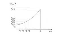
組織の焼灼規模を予測するための1つ以上の制御アルゴリズムは、制御装置300により実行される。より具体的には、特定のマイクロ波アンテナ、例えば、マイクロ波アンテナ100と関連する整流直流電圧(例えば、共振器132により生成された整流直流電圧Vdc)を、半径「r」を有する焼灼域「A」と相関させる概念を用い、組織の死滅または壊死を示すことができる。時間「t」の関数として生成された整流直流電圧Vdcの関係は、図3Bで例解される。マイクロ波焼灼の周期進行として、マイクロ波アンテナ100の「近接場」例えば、その焼灼部位に隣接する領域での電磁放射は、温度増加により引き起こされた組織の複合誘電率の変化が原因で、その焼灼周期にわたって変化する(例えば、増加する)。マイクロ波アンテナ100が所望の温度に組織を加熱している場合、対応する半径「r」(例えば、半径r1)を有する所望の焼灼域「A」が形成され、電磁放射が「近接場」で放出される。放射検出機器130の共振同軸供給装置134は、その電磁放射を検出し、対応する直流電圧、例えば、Vdc1が生成され、ACZM332に伝えられるように、共振器132の内部で電磁場を誘起する。より具体的には、ダイオード150は、共振器130の内部での時間t1〜t5における共振電磁場に対応する整流直流電圧Vdc1〜Vdc5を生み出す(例えば、図3Bを参照されたい)。 One or more control algorithms for predicting the ablation scale of the tissue are executed by the
「近接場」で放出された電磁放射の量は、与えられたマイクロ波アンテナにより変化し得るということに留意されたい。与えられたマイクロ波アンテナに対する電磁放射の特定量に寄与し得る要因としては、マイクロ波アンテナと関連する寸法(例えば、長さ、幅など)、銅、銀などのような、マイクロ波アンテナ(またはそれと関連する部分、例えば、放射部)を製作するために用いられる材料の種類、および、マイクロ波アンテナと関連する伝導性の先端の構成(例えば、鋭い、鈍い、曲がったなど)が挙げられるが、これらに限定されない。 It should be noted that the amount of electromagnetic radiation emitted in the “near field” can vary with a given microwave antenna. Factors that can contribute to the specific amount of electromagnetic radiation for a given microwave antenna include dimensions associated with the microwave antenna (eg, length, width, etc.), microwave antennas (or copper, silver, etc.) (or The type of material used to fabricate the part associated with it (eg, the radiating part) and the configuration of the conductive tip associated with the microwave antenna (eg, sharp, dull, bent, etc.) However, it is not limited to these.
例えば、球形(図3A)、半球形、楕円形(焼灼域が「A−2」と指定される図3C)などのような、任意の適切な構成を有する焼灼域「A」を創出するように、本開示のマイクロ波アンテナ100を構成することができる。1つの具体的な実施形態では、マイクロ波アンテナ100は、球形である焼灼域「A」を創出するように構成される(例えば、図3Aを参照されたい)。上述したように、マイクロ波アンテナ100が「近接場」内の組織を特定の温度に、例えば、時間t1において加熱している場合、電磁放射は「近接場」で放出され、電磁放射が共振器132の内部で誘起されるように、共振同軸供給装置134により検出され、その転換により、ACZM332に伝えられる、対応する整流直流電圧、例えば、Vdc1が生成される。マイクロ波アンテナ100と関連する整流直流電圧を焼灼された組織と相関させることにより、その焼灼域「A」の特定の規模(例えば、半径r1)および形状(例えば、球形)が示される。従って、マイクロ波アンテナ100と関連する整流直流電圧Vdc、例えば、Vdc1の測定値は、半径「r」、例えば、半径r1を有する焼灼域「A」に対応する。本開示の制御アルゴリズムは、焼灼規模を予測するために、特定の半径の特定のマイクロ波アンテナと関連する既知の整流直流電圧、Vdc1〜Vdc5を用いる。つまり、特定のマイクロ波アンテナ、例えば、マイクロ波アンテナ100と関連する閾電圧、例えば、Vdc5と、対応する半径、例えば、r5とは、1つ以上の参照表「D」内に編集され、記憶装置、例えば、記憶装置336内に記憶され、マイクロプロセッサ335および/またはAZCM332により呼び出し可能である。従って、特定のマイクロ波アンテナ、例えば、マイクロ波アンテナ100の閾整流直流電圧Vdcが、例えば、Vdc5に到達する場合、制御装置300に関連する1つ以上のモジュール、例えば、AZCM332は、マイクロ波アンテナ100に対する出力を適宜に調節するように制御装置200に命令する。この事象の組み合わせは、焼灼域「A」にr5にほぼ等しい半径を与えることになる。 Create an ablation zone “A” having any suitable configuration, such as, for example, a sphere (FIG. 3A), a hemisphere, an ellipse (FIG. 3C where the ablation zone is designated “A-2”), etc. In addition, the
例解される実施形態では、与えられたマイクロ波アンテナ、例えば、マイクロ波アンテナ100に関しては、時間t1〜t5で電圧測定が開始される。この場合、マイクロ波アンテナ100と関連する電圧、例えば、Vdc1〜Vdc5を、焼灼域「A」の中心から測定される場合、半径r1〜r5(半径rと集合的に呼ばれる)を有する複数の同心焼灼域により画定される焼灼域「A」と相関させることができる。この場合、特定の直流電圧、例えば、Vdc3が満たされる場合、制御装置300と関連する1つ以上のモジュール、例えば、AZCM332は、マイクロ波アンテナ100に対する出力を適宜に調節するように制御装置200に命令する。 In the illustrated embodiment, for a given microwave antenna, eg,
AZCM332はマイクロプロセッサ335から分離したモジュールであり得、あるいは、AZCM332をマイクロプロセッサ335とともに含めることができる。一実施形態では、AZCM332をマイクロ波アンテナ100上に操作可能に配置することができる。AZCM332は、1つ以上の制御モジュールから情報を受け取り、その情報を制御装置300および/またはマイクロプロセッサ335に提供する制御回路を含み得る。この場合、AZCM332、マイクロプロセッサ335、および/または制御装置300は参照表「D」を呼び出し、特定の焼灼域、例えば、半径r5を有する特定の焼灼域に対応する、マイクロ波組立部100と関連する閾整流直流電圧Vdc(例えば、Vdc5)が満たされていることを確認し、その後、マイクロ波アンテナに運搬されるマイクロ波エネルギーの量を調節するように発生器200に指示することができる。1つの具体的な実施形態では、マイクロ波アンテナ100と関連する記憶保存機器(図示せず)内に参照表「D」を保存することができる。より具体的には、参照表「D」を、マイクロ波アンテナ100の取手118および/または接続器126と操作的に関連する記憶保存機器内に保存することができ、マイクロプロセッサ335および/または記憶装置336内にダウンロードし、読み取り、保存し、その後、上記方法で呼び出して利用することができ、これは、特定のマイクロ波アンテナのために発生器200および/または制御装置300を再プログラムすることをなくすだろう。マイクロ波アンテナ100に関連する情報を含むように、記憶保存機器を構成することもできる。例えば、マイクロ波アンテナの種類、マイクロ波アンテナが治療するように構成される組織の種類、焼灼域の種類などのような情報を、当該マイクロ波アンテナと関連する保存機器内に保存することができる。この場合、焼灼域「A」を創出するように構成されるマイクロ波アンテナ100のそれとは異なる焼灼域、例えば、焼灼域「A−2」を創出するように構成されたマイクロ波アンテナを伴う使用のために、システム10の発生器200および/または制御装置300を適合させることができる。 The
図1Aで例解される実施形態では、発生器200は、流体供給ポンプ40に操作可能に連結されて示される。流体供給ポンプ40は、同様に、供給槽44に操作可能に連結される。実施形態では、マイクロプロセッサ335は、1つ以上の適切な種類のインターフェース、例えば、発生器200上に操作的に配置されたポート240を介して供給ポンプ40と操作的に連結し、それにより、開いたおよび/または閉じた制御ループ配列の何れかに従い、マイクロプロセッサ335が供給ポンプ40からマイクロ波アンテナ100への冷却流体42の出力を制御することが可能になる。制御装置300は、供給槽44からマイクロ波アンテナ100への冷却流体42の出力を制御するように、供給ポンプ40に信号を送ることができる。このようにして、冷却流体42は、マイクロ波アンテナ100に自動的に循環され、供給ポンプ40に戻される。特定の実施形態では、臨床医は、冷却流体42をマイクロ波アンテナ100から周囲の組織の中および/または付近に放出させるように、供給ポンプ40を手動で制御することができる。 In the embodiment illustrated in FIG. 1A,
システム10の操作がここで記載される。最初に、マイクロ波アンテナ100が発生器200に接続される。1つの具体的な実施形態では、発生器200および/または制御装置300と関連する1つ以上のモジュール、例えば、AZCM332は、マイクロ波アンテナ100と関連する保存機器からのデータ、例えば、マイクロ波アンテナの種類、治療すべき組織の種類などを読み取り、および/またはダウンロードする。その後、発生器200を作動させ、組織を焼灼することができるように、マイクロ波エネルギーをマイクロ波アンテナ100の放射部138に供給することができる。組織の焼灼の最中に、マイクロ波アンテナ100の共振器132で所定の整流直流電圧Vdc、例えば、V5に到達する(すなわち、ダイオード150の全体にわたる整流電圧が存在する)場合、AZCM332は、マイクロ波エネルギーを適宜に調節するように発生器200に指示する。前述の事象の順序では、AZCM332は実時間において機能し、適切な割合の均一な焼灼域(例えば、半径r5を有する焼灼域「A」)が隣接する組織に対して最小の損傷を伴うか、または全く損傷を伴わずに形成されるように、焼灼域に対するマイクロ波エネルギーの量を制御する。 The operation of
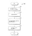
図5を参照すると、焼灼を受ける組織の温度を監視するための方法400が例解されている。ステップ402では、発生器200からのマイクロ波エネルギーが、組織の焼灼部位に隣接するマイクロ波アンテナ100に伝達される。ステップ404では、マイクロ波アンテナ100と関連する直流電圧Vdcが監視される。ステップ406では、マイクロ波アンテナ100で所定の整流直流電圧Vdcに到達する場合、検出信号が発生器200に伝えられる。ステップ408では、発生器200からマイクロ波アンテナ100へのマイクロ波エネルギーの量を調節することができる。 Referring to FIG. 5, a
前述の内容から、かつ、様々な作図を参照すると、当業者は、本開示の範囲から逸脱することなく、本開示に対して特定の修正を行うこともできることを十分理解するだろう。例えば、代替の一実施形態では、放射検出機器130(またはそれに関連する操作的な構成部)を、マイクロ波アンテナ100の放射部138に隣接する心棒112に沿って内側に(図6)、あるいは、マイクロ波アンテナ512の放射部518に隣接する供給線520に沿って内側に、操作可能に配置することができる。図6で例解される実施形態では、伝導性の部材142と144とを含む共振器130および同軸供給装置134は、一対の支持体160を介してカテーテル154に対して固定支持される。放射検出機器130の操作およびそれに関連する操作的な構成部は、取手118の内部に配置される放射検出機器130に対して上記のような方法で機能し、そのために、これをさらに詳細に記載することはない。 From the foregoing, and with reference to various drawings, one of ordinary skill in the art will appreciate that certain modifications can be made to the present disclosure without departing from the scope of the present disclosure. For example, in an alternative embodiment, the radiation detection device 130 (or its associated operational component) is moved inwardly along the
伝導性部分142および144(または、共振器132と関連する他の操作的な構成部)を、互いに、および/または、マイクロ波アンテナ100と関連する周囲の構成部から絶縁つまり電気的に分離するように構成された、絶縁性の被覆または被鞘(図示せず)で、伝導性部分142および144の一方または両方を被覆することが意図される。より具体的には、それぞれの伝導性部分144および142の近位端および遠位端は、伝導性部分142と144との間の短絡を防止するための絶縁性材料(明示せず)を含み得る。代替的に、またはその組み合わせにおいて、伝導性部分142および144の一方または両方の外側周囲面を、絶縁性材料により被覆または形成することができる。
本開示のいくつかの実施形態が図面で示され、および/または本明細書で検討されているものの、本開示は当該技術が許容するほど範囲が広範であり、かつ本明細書が同様に解釈されることを目的とするので、本開示を当該実施形態に限定することを目的としない。それ故、上の記載を制限としてではなく、単に具体的な実施形態の例示として解釈されたい。当業者は、本明細書に添付されている特許請求の範囲および趣旨の範囲内にある他の修正を構想するだろう。 Although some embodiments of the present disclosure are shown in the drawings and / or discussed herein, the present disclosure is as broad as the art allows, and the present description is similarly construed Therefore, the present disclosure is not intended to be limited to the embodiment. Therefore, the above description should not be construed as limiting, but merely as exemplifications of specific embodiments. Those skilled in the art will envision other modifications within the scope and spirit of the claims appended hereto.
Claims (19)
Translated fromJapanese少なくとも1つの制御アルゴリズムを実行するためのマイクロプロセッサを含む電力源と、
焼灼域を形成するために、前記電力源から組織にマイクロ波エネルギーを運搬するように構成されたマイクロ波アンテナと、
前記マイクロ波アンテナ上に操作可能に配置された放射検出機器であって、前記放射検出機器は前記焼灼域の半径に対応する電圧を生成するように構成された放射検出機器と、を備え、
前記放射検出機器が前記電力源と関連する少なくとも1つのモジュールと操作的に連通し、所定の閾電圧が前記焼灼域の半径に対応して測定される場合、前記少なくとも1つのモジュールが信号を引き起こす、システム。A system for monitoring the scale of shochu,
A power source including a microprocessor for executing at least one control algorithm;
A microwave antenna configured to carry microwave energy from the power source to tissue to form an ablation zone;
A radiation detection device operably disposed on the microwave antenna, the radiation detection device comprising: a radiation detection device configured to generate a voltage corresponding to a radius of the ablation zone;
If the radiation detection device is in operative communication with at least one module associated with the power source and a predetermined threshold voltage is measured corresponding to the radius of the ablation zone, the at least one module causes a signal ,system.
をさらに備える、請求項1に記載のシステム。At least one fluid pump configured to supply cooling fluid to the microwave antenna to facilitate cooling of one of the tissue adjacent to the microwave antenna and the ablation zone;
The system of claim 1, further comprising:
組織の焼灼域を形成するために、電力源からマイクロ波アンテナにマイクロ波エネルギーを伝達することと、
前記組織の焼灼域が形成する際に、前記マイクロ波アンテナに沿って組織の温度の近位伝播を監視することと、
前記マイクロ波アンテナの内部で所定の直流電圧に到達する場合、検出信号を伝えることと、
前記電力源から前記マイクロ波アンテナへのマイクロ波エネルギーの量を調節することと、
を含む、方法。A method for monitoring the temperature of tissue undergoing ablation, said method comprising:
Transmitting microwave energy from a power source to a microwave antenna to form a tissue ablation zone;
Monitoring the proximal propagation of tissue temperature along the microwave antenna as the tissue ablation zone forms;
When reaching a predetermined DC voltage inside the microwave antenna, transmitting a detection signal;
Adjusting the amount of microwave energy from the power source to the microwave antenna;
Including a method.
Applications Claiming Priority (2)
| Application Number | Priority Date | Filing Date | Title |
|---|---|---|---|
| US12/607,221 | 2009-10-28 | ||
| US12/607,221US8430871B2 (en) | 2009-10-28 | 2009-10-28 | System and method for monitoring ablation size |
Related Child Applications (1)
| Application Number | Title | Priority Date | Filing Date |
|---|---|---|---|
| JP2015028666ADivisionJP6017606B2 (en) | 2009-10-28 | 2015-02-17 | System and method for monitoring shochu scale |
Publications (2)
| Publication Number | Publication Date |
|---|---|
| JP2011092720Atrue JP2011092720A (en) | 2011-05-12 |
| JP5704559B2 JP5704559B2 (en) | 2015-04-22 |
Family
ID=43602914
Family Applications (4)
| Application Number | Title | Priority Date | Filing Date |
|---|---|---|---|
| JP2010241818AActiveJP5704559B2 (en) | 2009-10-28 | 2010-10-28 | System and method for monitoring shochu scale |
| JP2015028666AExpired - Fee RelatedJP6017606B2 (en) | 2009-10-28 | 2015-02-17 | System and method for monitoring shochu scale |
| JP2016190063AActiveJP6325621B2 (en) | 2009-10-28 | 2016-09-28 | System and method for monitoring shochu scale |
| JP2018076573APendingJP2018110928A (en) | 2009-10-28 | 2018-04-12 | System and method for monitoring ablation size |
Family Applications After (3)
| Application Number | Title | Priority Date | Filing Date |
|---|---|---|---|
| JP2015028666AExpired - Fee RelatedJP6017606B2 (en) | 2009-10-28 | 2015-02-17 | System and method for monitoring shochu scale |
| JP2016190063AActiveJP6325621B2 (en) | 2009-10-28 | 2016-09-28 | System and method for monitoring shochu scale |
| JP2018076573APendingJP2018110928A (en) | 2009-10-28 | 2018-04-12 | System and method for monitoring ablation size |
Country Status (3)
| Country | Link |
|---|---|
| US (3) | US8430871B2 (en) |
| EP (1) | EP2316370B1 (en) |
| JP (4) | JP5704559B2 (en) |
Cited By (12)
| Publication number | Priority date | Publication date | Assignee | Title |
|---|---|---|---|---|
| JP2012130695A (en)* | 2010-12-23 | 2012-07-12 | Vivant Medical Inc | Microwave field-detecting needle assembly, method for manufacturing the same, method for adjusting intra-tissue irradiation cauterization area using the same, and system including the same |
| JP2016163758A (en)* | 2011-12-21 | 2016-09-08 | ニューウェーブ メディカル, インコーポレイテッドNeuwave Medical, Inc. | Energy supply system |
| US9861440B2 (en) | 2010-05-03 | 2018-01-09 | Neuwave Medical, Inc. | Energy delivery systems and uses thereof |
| US9877783B2 (en) | 2009-07-28 | 2018-01-30 | Neuwave Medical, Inc. | Energy delivery systems and uses thereof |
| JP2018110928A (en)* | 2009-10-28 | 2018-07-19 | コビディエン エルピー | System and method for monitoring ablation size |
| US10363092B2 (en) | 2006-03-24 | 2019-07-30 | Neuwave Medical, Inc. | Transmission line with heat transfer ability |
| US10531917B2 (en) | 2016-04-15 | 2020-01-14 | Neuwave Medical, Inc. | Systems and methods for energy delivery |
| US10952792B2 (en) | 2015-10-26 | 2021-03-23 | Neuwave Medical, Inc. | Energy delivery systems and uses thereof |
| US11389235B2 (en) | 2006-07-14 | 2022-07-19 | Neuwave Medical, Inc. | Energy delivery systems and uses thereof |
| US11576723B2 (en) | 2006-07-14 | 2023-02-14 | Neuwave Medical, Inc. | Energy delivery systems and uses thereof |
| US11672596B2 (en) | 2018-02-26 | 2023-06-13 | Neuwave Medical, Inc. | Energy delivery devices with flexible and adjustable tips |
| US11832879B2 (en) | 2019-03-08 | 2023-12-05 | Neuwave Medical, Inc. | Systems and methods for energy delivery |
Families Citing this family (45)
| Publication number | Priority date | Publication date | Assignee | Title |
|---|---|---|---|---|
| US7553309B2 (en) | 2004-10-08 | 2009-06-30 | Covidien Ag | Electrosurgical system employing multiple electrodes and method thereof |
| US8323275B2 (en) | 2009-06-19 | 2012-12-04 | Vivant Medical, Inc. | Laparoscopic port with microwave rectifier |
| US9113925B2 (en)* | 2009-09-09 | 2015-08-25 | Covidien Lp | System and method for performing an ablation procedure |
| US8069553B2 (en) | 2009-09-09 | 2011-12-06 | Vivant Medical, Inc. | Method for constructing a dipole antenna |
| US9095359B2 (en) | 2009-09-18 | 2015-08-04 | Covidien Lp | Tissue ablation system with energy distribution |
| US8568398B2 (en) | 2009-09-29 | 2013-10-29 | Covidien Lp | Flow rate monitor for fluid cooled microwave ablation probe |
| US8568401B2 (en) | 2009-10-27 | 2013-10-29 | Covidien Lp | System for monitoring ablation size |
| US8382750B2 (en)* | 2009-10-28 | 2013-02-26 | Vivant Medical, Inc. | System and method for monitoring ablation size |
| US8469953B2 (en) | 2009-11-16 | 2013-06-25 | Covidien Lp | Twin sealing chamber hub |
| US8394092B2 (en)* | 2009-11-17 | 2013-03-12 | Vivant Medical, Inc. | Electromagnetic energy delivery devices including an energy applicator array and electrosurgical systems including same |
| US8764744B2 (en) | 2010-01-25 | 2014-07-01 | Covidien Lp | System for monitoring ablation size |
| US8491579B2 (en) | 2010-02-05 | 2013-07-23 | Covidien Lp | Electrosurgical devices with choke shorted to biological tissue |
| US8968288B2 (en) | 2010-02-19 | 2015-03-03 | Covidien Lp | Ablation devices with dual operating frequencies, systems including same, and methods of adjusting ablation volume using same |
| US8617153B2 (en) | 2010-02-26 | 2013-12-31 | Covidien Lp | Tunable microwave ablation probe |
| US8728067B2 (en) | 2010-03-08 | 2014-05-20 | Covidien Lp | Microwave antenna probe having a deployable ground plane |
| US8409188B2 (en) | 2010-03-26 | 2013-04-02 | Covidien Lp | Ablation devices with adjustable radiating section lengths, electrosurgical systems including same, and methods of adjusting ablation fields using same |
| US10039601B2 (en) | 2010-03-26 | 2018-08-07 | Covidien Lp | Ablation devices with adjustable radiating section lengths, electrosurgical systems including same, and methods of adjusting ablation fields using same |
| US9192436B2 (en) | 2010-05-25 | 2015-11-24 | Covidien Lp | Flow rate verification monitor for fluid-cooled microwave ablation probe |
| US8652127B2 (en) | 2010-05-26 | 2014-02-18 | Covidien Lp | System and method for chemically cooling an ablation antenna |
| US9241762B2 (en) | 2010-06-03 | 2016-01-26 | Covidien Lp | Specific absorption rate measurement and energy-delivery device characterization using image analysis |
| US8672933B2 (en) | 2010-06-30 | 2014-03-18 | Covidien Lp | Microwave antenna having a reactively-loaded loop configuration |
| US10588684B2 (en) | 2010-07-19 | 2020-03-17 | Covidien Lp | Hydraulic conductivity monitoring to initiate tissue division |
| US9770294B2 (en) | 2011-01-05 | 2017-09-26 | Covidien Lp | Energy-delivery devices with flexible fluid-cooled shaft, inflow/outflow junctions suitable for use with same, and systems including same |
| US9028476B2 (en) | 2011-02-03 | 2015-05-12 | Covidien Lp | Dual antenna microwave resection and ablation device, system and method of use |
| US8992413B2 (en) | 2011-05-31 | 2015-03-31 | Covidien Lp | Modified wet tip antenna design |
| US9901398B2 (en) | 2012-06-29 | 2018-02-27 | Covidien Lp | Microwave antenna probes |
| US9993295B2 (en) | 2012-08-07 | 2018-06-12 | Covidien Lp | Microwave ablation catheter and method of utilizing the same |
| US9993283B2 (en) | 2012-10-02 | 2018-06-12 | Covidien Lp | Selectively deformable ablation device |
| US9668802B2 (en) | 2012-10-02 | 2017-06-06 | Covidien Lp | Devices and methods for optical detection of tissue contact |
| US9901399B2 (en) | 2012-12-17 | 2018-02-27 | Covidien Lp | Ablation probe with tissue sensing configuration |
| US10195467B2 (en)* | 2013-02-21 | 2019-02-05 | Boston Scientific Scimed, Inc. | Ablation catheter system with wireless radio frequency temperature sensor |
| US9101344B2 (en) | 2013-03-15 | 2015-08-11 | Covidien Lp | Recirculating cooling system for energy delivery device |
| US9682190B2 (en) | 2013-03-15 | 2017-06-20 | Covidien Lp | Recirculating cooling system for energy delivery device |
| US9987087B2 (en) | 2013-03-29 | 2018-06-05 | Covidien Lp | Step-down coaxial microwave ablation applicators and methods for manufacturing same |
| US11227427B2 (en) | 2014-08-11 | 2022-01-18 | Covidien Lp | Treatment procedure planning system and method |
| US10624697B2 (en) | 2014-08-26 | 2020-04-21 | Covidien Lp | Microwave ablation system |
| US10813691B2 (en) | 2014-10-01 | 2020-10-27 | Covidien Lp | Miniaturized microwave ablation assembly |
| AU2015374244B2 (en) | 2014-12-31 | 2019-11-21 | Covidien Lp | System and method for treating COPD and emphysema |
| US10813692B2 (en) | 2016-02-29 | 2020-10-27 | Covidien Lp | 90-degree interlocking geometry for introducer for facilitating deployment of microwave radiating catheter |
| US20170319275A1 (en) | 2016-05-03 | 2017-11-09 | Covidien Lp | Recirculating cooling systems for use with energy delivery devices |
| US10376309B2 (en) | 2016-08-02 | 2019-08-13 | Covidien Lp | Ablation cable assemblies and a method of manufacturing the same |
| US11197715B2 (en) | 2016-08-02 | 2021-12-14 | Covidien Lp | Ablation cable assemblies and a method of manufacturing the same |
| US11065053B2 (en) | 2016-08-02 | 2021-07-20 | Covidien Lp | Ablation cable assemblies and a method of manufacturing the same |
| US11071586B2 (en) | 2017-06-05 | 2021-07-27 | Covidien Lp | Cooling systems for energy delivery devices |
| EP3443921B1 (en)* | 2017-08-17 | 2020-09-30 | Micrima Limited | A medical imaging system |
Citations (5)
| Publication number | Priority date | Publication date | Assignee | Title |
|---|---|---|---|---|
| JPH10243947A (en)* | 1997-03-04 | 1998-09-14 | Olympus Optical Co Ltd | High-frequency device |
| JP2001037775A (en)* | 1999-07-26 | 2001-02-13 | Olympus Optical Co Ltd | Treatment device |
| JP2002507924A (en)* | 1997-07-03 | 2002-03-12 | ネオサーミア コーポレイション | Method and apparatus for therapeutic ablation of a volume of biological tissue |
| JP2007532024A (en)* | 2003-07-18 | 2007-11-08 | ビバント メディカル インコーポレイテッド | Apparatus and method for cooling a microwave antenna |
| JP2009000528A (en)* | 2007-06-20 | 2009-01-08 | Vivant Medical Inc | Reflected power monitoring for microwave applications |
Family Cites Families (250)
| Publication number | Priority date | Publication date | Assignee | Title |
|---|---|---|---|---|
| DE390937C (en) | 1922-10-13 | 1924-03-03 | Adolf Erb | Device for internal heating of furnace furnaces for hardening, tempering, annealing, quenching and melting |
| DE1099658B (en) | 1959-04-29 | 1961-02-16 | Siemens Reiniger Werke Ag | Automatic switch-on device for high-frequency surgical devices |
| FR1275415A (en) | 1960-09-26 | 1961-11-10 | Device for detecting disturbances for electrical installations, in particular electrosurgery | |
| DE1139927B (en) | 1961-01-03 | 1962-11-22 | Friedrich Laber | High-frequency surgical device |
| DE1149832C2 (en) | 1961-02-25 | 1977-10-13 | Siemens AG, 1000 Berlin und 8000 München | HIGH FREQUENCY SURGICAL EQUIPMENT |
| FR1347865A (en) | 1962-11-22 | 1964-01-04 | Improvements to diathermo-coagulation devices | |
| DE1439302B2 (en) | 1963-10-26 | 1971-05-19 | Siemens AG, 1000 Berlin u 8000 München | High frequency surgical device |
| SU401367A1 (en) | 1971-10-05 | 1973-10-12 | Тернопольский государственный медицинский институт | BIAKTIVNYE ELECTRO SURGICAL INSTRUMENT |
| FR2235669A1 (en) | 1973-07-07 | 1975-01-31 | Lunacek Boris | Gynaecological sterilisation instrument - has hollow electrode protruding from the end of a curved ended tube |
| GB1480736A (en) | 1973-08-23 | 1977-07-20 | Matburn Ltd | Electrodiathermy apparatus |
| FR2251864A1 (en) | 1973-11-21 | 1975-06-13 | Termiflex Corp | Portable input and output unit for connection to a data processor - is basically a calculator with transmitter and receiver |
| DE2407559C3 (en) | 1974-02-16 | 1982-01-21 | Dornier System Gmbh, 7990 Friedrichshafen | Heat probe |
| DE2415263A1 (en) | 1974-03-29 | 1975-10-02 | Aesculap Werke Ag | Surgical H.F. coagulation probe has electrode tongs - with exposed ends of insulated conductors forming tong-jaws |
| DE2429021C2 (en) | 1974-06-18 | 1983-12-08 | Erbe Elektromedizin GmbH, 7400 Tübingen | Remote switching device for an HF surgical device |
| FR2276027A1 (en) | 1974-06-25 | 1976-01-23 | Medical Plastics Inc | Plate electrode with connector - is clamped between connector jaws held by releasable locking device |
| DE2460481A1 (en) | 1974-12-20 | 1976-06-24 | Delma Elektro Med App | Electrode grip for remote HF surgical instrument switching - has shaped insulated piece with contact ring of sterilizable (silicon) rubber |
| US4237887A (en) | 1975-01-23 | 1980-12-09 | Valleylab, Inc. | Electrosurgical device |
| DE2504280C3 (en) | 1975-02-01 | 1980-08-28 | Hans Heinrich Prof. Dr. 8035 Gauting Meinke | Device for cutting and / or coagulating human tissue with high frequency current |
| CA1064581A (en) | 1975-06-02 | 1979-10-16 | Stephen W. Andrews | Pulse control circuit and method for electrosurgical units |
| FR2315286A2 (en) | 1975-06-26 | 1977-01-21 | Lamidey Marcel | H.F. blood coagulating dissecting forceps - with adjustable stops to vary clamping space and circuit making contacts |
| DE2540968C2 (en) | 1975-09-13 | 1982-12-30 | Erbe Elektromedizin GmbH, 7400 Tübingen | Device for switching on the coagulation current of a bipolar coagulation forceps |
| FR2390968A1 (en) | 1977-05-16 | 1978-12-15 | Skovajsa Joseph | Local acupuncture treatment appts. - has oblong head with end aperture and contains laser diode unit (NL 20.11.78) |
| SU727201A2 (en) | 1977-11-02 | 1980-04-15 | Киевский Научно-Исследовательский Институт Нейрохирургии | Electric surgical apparatus |
| DE2803275C3 (en) | 1978-01-26 | 1980-09-25 | Aesculap-Werke Ag Vormals Jetter & Scheerer, 7200 Tuttlingen | Remote switching device for switching a monopolar HF surgical device |
| DE2823291A1 (en) | 1978-05-27 | 1979-11-29 | Rainer Ing Grad Koch | Coagulation instrument automatic HF switching circuit - has first lead to potentiometer and second to transistor base |
| DE2946728A1 (en) | 1979-11-20 | 1981-05-27 | Erbe Elektromedizin GmbH & Co KG, 7400 Tübingen | HF surgical appts. for use with endoscope - provides cutting or coagulation current at preset intervals and of selected duration |
| USD263020S (en) | 1980-01-22 | 1982-02-16 | Rau Iii David M | Retractable knife |
| USD266842S (en) | 1980-06-27 | 1982-11-09 | Villers Mark W | Phonograph record spacer |
| USD278306S (en) | 1980-06-30 | 1985-04-09 | Mcintosh Lois A | Microwave oven rack |
| JPS5778844A (en) | 1980-11-04 | 1982-05-17 | Kogyo Gijutsuin | Lasre knife |
| DE3045996A1 (en) | 1980-12-05 | 1982-07-08 | Medic Eschmann Handelsgesellschaft für medizinische Instrumente mbH, 2000 Hamburg | Electro-surgical scalpel instrument - has power supply remotely controlled by surgeon |
| FR2502935B1 (en) | 1981-03-31 | 1985-10-04 | Dolley Roger | METHOD AND DEVICE FOR CONTROLLING THE COAGULATION OF TISSUES USING A HIGH FREQUENCY CURRENT |
| DE3120102A1 (en) | 1981-05-20 | 1982-12-09 | F.L. Fischer GmbH & Co, 7800 Freiburg | ARRANGEMENT FOR HIGH-FREQUENCY COAGULATION OF EGG WHITE FOR SURGICAL PURPOSES |
| FR2517953A1 (en) | 1981-12-10 | 1983-06-17 | Alvar Electronic | Diaphanometer for optical examination of breast tissue structure - measures tissue transparency using two plates and optical fibre bundle cooperating with photoelectric cells |
| FR2573301B3 (en) | 1984-11-16 | 1987-04-30 | Lamidey Gilles | SURGICAL PLIERS AND ITS CONTROL AND CONTROL APPARATUS |
| DE3510586A1 (en) | 1985-03-23 | 1986-10-02 | Erbe Elektromedizin GmbH, 7400 Tübingen | Control device for a high-frequency surgical instrument |
| USD295893S (en) | 1985-09-25 | 1988-05-24 | Acme United Corporation | Disposable surgical clamp |
| USD295894S (en) | 1985-09-26 | 1988-05-24 | Acme United Corporation | Disposable surgical scissors |
| US4643186A (en)* | 1985-10-30 | 1987-02-17 | Rca Corporation | Percutaneous transluminal microwave catheter angioplasty |
| US4629847A (en)* | 1985-11-07 | 1986-12-16 | Gics Paul W | Resonator device for a microwave heat applicator |
| DE3604823C2 (en) | 1986-02-15 | 1995-06-01 | Lindenmeier Heinz | High frequency generator with automatic power control for high frequency surgery |
| JPH055106Y2 (en) | 1986-02-28 | 1993-02-09 | ||
| EP0246350A1 (en) | 1986-05-23 | 1987-11-25 | Erbe Elektromedizin GmbH. | Coagulation electrode |
| JPS62284659A (en) | 1986-05-31 | 1987-12-10 | 株式会社島津製作所 | Ultrasonic hyperthermia apparatus |
| JPH0540112Y2 (en) | 1987-03-03 | 1993-10-12 | ||
| DE3711511C1 (en) | 1987-04-04 | 1988-06-30 | Hartmann & Braun Ag | Method for determining gas concentrations in a gas mixture and sensor for measuring thermal conductivity |
| DE8712328U1 (en) | 1987-09-11 | 1988-02-18 | Jakoubek, Franz, 7201 Emmingen-Liptingen | Endoscopy forceps |
| JPH01244321A (en) | 1988-03-25 | 1989-09-28 | Hitachi Ltd | Method for measuring temperature within living body |
| US4945912A (en)* | 1988-11-25 | 1990-08-07 | Sensor Electronics, Inc. | Catheter with radiofrequency heating applicator |
| DE3904558C2 (en) | 1989-02-15 | 1997-09-18 | Lindenmeier Heinz | Automatically power-controlled high-frequency generator for high-frequency surgery |
| DE3942998C2 (en) | 1989-12-27 | 1998-11-26 | Delma Elektro Med App | High frequency electrosurgical unit |
| JP2806511B2 (en) | 1990-07-31 | 1998-09-30 | 松下電工株式会社 | Manufacturing method of sintered alloy |
| JP2951418B2 (en) | 1991-02-08 | 1999-09-20 | トキコ株式会社 | Sample liquid component analyzer |
| DE4122050C2 (en) | 1991-07-03 | 1996-05-30 | Gore W L & Ass Gmbh | Antenna arrangement with supply line for medical heat application in body cavities |
| DE4238263A1 (en) | 1991-11-15 | 1993-05-19 | Minnesota Mining & Mfg | Adhesive comprising hydrogel and crosslinked polyvinyl:lactam - is used in electrodes for biomedical application providing low impedance and good mechanical properties when water and/or moisture is absorbed from skin |
| DE4205213A1 (en) | 1992-02-20 | 1993-08-26 | Delma Elektro Med App | HIGH FREQUENCY SURGERY DEVICE |
| FR2687786B1 (en) | 1992-02-26 | 1994-05-06 | Pechiney Recherche | MEASUREMENT OF ELECTRICAL RESISTIVITY AND HIGH TEMPERATURE THERMAL CONDUCTIVITY OF REFRACTORY PRODUCTS. |
| US5369251A (en)* | 1992-09-14 | 1994-11-29 | Kdc Technology Corp. | Microwave interstitial hyperthermia probe |
| USD354218S (en) | 1992-10-01 | 1995-01-10 | Fiberslab Pty Limited | Spacer for use in concrete construction |
| DE4303882C2 (en) | 1993-02-10 | 1995-02-09 | Kernforschungsz Karlsruhe | Combination instrument for separation and coagulation for minimally invasive surgery |
| GB9309142D0 (en) | 1993-05-04 | 1993-06-16 | Gyrus Medical Ltd | Laparoscopic instrument |
| FR2711066B1 (en) | 1993-10-15 | 1995-12-01 | Sadis Bruker Spectrospin | Antenna for heating fabrics by microwave and probe comprising one or more of these antennas. |
| GB9322464D0 (en) | 1993-11-01 | 1993-12-22 | Gyrus Medical Ltd | Electrosurgical apparatus |
| DE4339049C2 (en) | 1993-11-16 | 2001-06-28 | Erbe Elektromedizin | Surgical system configuration facility |
| CN1079269C (en) | 1993-11-17 | 2002-02-20 | 刘中一 | Multi-frequency micro-wave therapeutic instrument |
| JP3063513B2 (en)* | 1994-02-10 | 2000-07-12 | 松下電器産業株式会社 | Microwave detection feed circuit |
| GB9413070D0 (en) | 1994-06-29 | 1994-08-17 | Gyrus Medical Ltd | Electrosurgical apparatus |
| US5549639A (en)* | 1994-09-16 | 1996-08-27 | Sandia Corporation | Non-invasive hyperthermia apparatus including coaxial applicator having a non-invasive radiometric receiving antenna incorporated therein and method of use thereof |
| GB9425781D0 (en) | 1994-12-21 | 1995-02-22 | Gyrus Medical Ltd | Electrosurgical instrument |
| US6575969B1 (en)* | 1995-05-04 | 2003-06-10 | Sherwood Services Ag | Cool-tip radiofrequency thermosurgery electrode system for tumor ablation |
| WO1996039086A1 (en) | 1995-06-06 | 1996-12-12 | Valleylab Inc. | Power control for an electrosurgical generator |
| JP3500228B2 (en) | 1995-06-21 | 2004-02-23 | オリンパス株式会社 | Endoscope treatment instrument insertion / extraction device |
| US6293942B1 (en) | 1995-06-23 | 2001-09-25 | Gyrus Medical Limited | Electrosurgical generator method |
| US6132425A (en)* | 1995-08-15 | 2000-10-17 | Gough; Edward J. | Cell necrosis apparatus |
| US6059780A (en)* | 1995-08-15 | 2000-05-09 | Rita Medical Systems, Inc. | Multiple antenna ablation apparatus and method with cooling element |
| US5672173A (en)* | 1995-08-15 | 1997-09-30 | Rita Medical Systems, Inc. | Multiple antenna ablation apparatus and method |
| JP3782495B2 (en) | 1995-10-27 | 2006-06-07 | アルフレッサファーマ株式会社 | Microwave surgical device |
| DE19608716C1 (en) | 1996-03-06 | 1997-04-17 | Aesculap Ag | Bipolar surgical holding instrument |
| DE29616210U1 (en) | 1996-09-18 | 1996-11-14 | Olympus Winter & Ibe Gmbh, 22045 Hamburg | Handle for surgical instruments |
| DE19643127A1 (en) | 1996-10-18 | 1998-04-23 | Berchtold Gmbh & Co Geb | High frequency surgical device and method for its operation |
| US5923475A (en) | 1996-11-27 | 1999-07-13 | Eastman Kodak Company | Laser printer using a fly's eye integrator |
| US6380815B1 (en)* | 1997-01-23 | 2002-04-30 | Vega Grieshaber Kg | Microwave pulse generator |
| DE19717411A1 (en) | 1997-04-25 | 1998-11-05 | Aesculap Ag & Co Kg | Monitoring of thermal loading of patient tissue in contact region of neutral electrode of HF treatment unit |
| DE59712260D1 (en) | 1997-06-06 | 2005-05-12 | Endress & Hauser Gmbh & Co Kg | Microwave level gauge |
| DE19751108A1 (en) | 1997-11-18 | 1999-05-20 | Beger Frank Michael Dipl Desig | Electrosurgical operation tool, especially for diathermy |
| EP0923907A1 (en) | 1997-12-19 | 1999-06-23 | Gyrus Medical Limited | An electrosurgical instrument |
| DE19801173C1 (en) | 1998-01-15 | 1999-07-15 | Kendall Med Erzeugnisse Gmbh | Clamp connector for film electrodes |
| US6222193B1 (en)* | 1998-10-06 | 2001-04-24 | Neoprobe Corporation | Radiation responsive surgical probe apparatus |
| DE19848540A1 (en) | 1998-10-21 | 2000-05-25 | Reinhard Kalfhaus | Circuit layout and method for operating a single- or multiphase current inverter connects an AC voltage output to a primary winding and current and a working resistance to a transformer's secondary winding and current. |
| USD449886S1 (en) | 1998-10-23 | 2001-10-30 | Sherwood Services Ag | Forceps with disposable electrode |
| USD424694S (en) | 1998-10-23 | 2000-05-09 | Sherwood Services Ag | Forceps |
| USD425201S (en) | 1998-10-23 | 2000-05-16 | Sherwood Services Ag | Disposable electrode assembly |
| EP2206475A3 (en) | 1998-12-18 | 2010-11-17 | Celon AG Medical Instruments | Electrode assembly for a surgical instrument for carrying out an electrothermal coagulation of tissue |
| GB9904373D0 (en) | 1999-02-25 | 1999-04-21 | Microsulis Plc | Radiation applicator |
| USD424693S (en) | 1999-04-08 | 2000-05-09 | Pruter Rick L | Needle guide for attachment to an ultrasound transducer probe |
| US6325796B1 (en)* | 1999-05-04 | 2001-12-04 | Afx, Inc. | Microwave ablation instrument with insertion probe |
| GB9911956D0 (en) | 1999-05-21 | 1999-07-21 | Gyrus Medical Ltd | Electrosurgery system and method |
| GB9911954D0 (en) | 1999-05-21 | 1999-07-21 | Gyrus Medical Ltd | Electrosurgery system and instrument |
| GB9912625D0 (en) | 1999-05-28 | 1999-07-28 | Gyrus Medical Ltd | An electrosurgical generator and system |
| GB9912627D0 (en) | 1999-05-28 | 1999-07-28 | Gyrus Medical Ltd | An electrosurgical instrument |
| GB9913652D0 (en) | 1999-06-11 | 1999-08-11 | Gyrus Medical Ltd | An electrosurgical generator |
| JP2001003776A (en) | 1999-06-22 | 2001-01-09 | Mitsubishi Electric Corp | Automatic transmission control device |
| JP2001037776A (en)* | 1999-07-26 | 2001-02-13 | Olympus Optical Co Ltd | Treatment device |
| US7300436B2 (en)* | 2000-02-22 | 2007-11-27 | Rhytec Limited | Tissue resurfacing |
| JP2001231870A (en) | 2000-02-23 | 2001-08-28 | Olympus Optical Co Ltd | Moisturizing treatment apparatus |
| JP4723156B2 (en)* | 2000-03-31 | 2011-07-13 | アンジオ ダイナミクス インコーポレイテッド | Tissue biopsy and treatment equipment |
| DE10027727C1 (en) | 2000-06-03 | 2001-12-06 | Aesculap Ag & Co Kg | Scissors-shaped or forceps-shaped surgical instrument |
| US6986764B2 (en)* | 2000-12-15 | 2006-01-17 | Laserscope | Method and system for photoselective vaporization of the prostate, and other tissue |
| US20020087079A1 (en)* | 2001-01-03 | 2002-07-04 | Leon Kaufman | Position sensitive catheter having scintillation detectors |
| US20080125775A1 (en)* | 2001-02-28 | 2008-05-29 | Morris David L | Hemostasis and/or coagulation of tissue |
| USD457958S1 (en) | 2001-04-06 | 2002-05-28 | Sherwood Services Ag | Vessel sealer and divider |
| USD457959S1 (en) | 2001-04-06 | 2002-05-28 | Sherwood Services Ag | Vessel sealer |
| US6878147B2 (en) | 2001-11-02 | 2005-04-12 | Vivant Medical, Inc. | High-strength microwave antenna assemblies |
| DE10224154A1 (en) | 2002-05-27 | 2003-12-18 | Celon Ag Medical Instruments | Application device for electrosurgical device for body tissue removal via of HF current has electrode subset selected from active electrode set in dependence on measured impedance of body tissue |
| USD487039S1 (en) | 2002-11-27 | 2004-02-24 | Robert Bosch Corporation | Spacer |
| DE10310765A1 (en) | 2003-03-12 | 2004-09-30 | Dornier Medtech Systems Gmbh | Medical thermotherapy instrument, e.g. for treatment of benign prostatic hypertrophy (BPH), has an antenna that can be set to radiate at least two different frequency microwave signals |
| WO2004086994A1 (en) | 2003-03-28 | 2004-10-14 | C.R. Bard, Inc. | Method and apparatus for electrosurgical ablation |
| USD499181S1 (en) | 2003-05-15 | 2004-11-30 | Sherwood Services Ag | Handle for a vessel sealer and divider |
| USD496997S1 (en) | 2003-05-15 | 2004-10-05 | Sherwood Services Ag | Vessel sealer and divider |
| DE10328514B3 (en) | 2003-06-20 | 2005-03-03 | Aesculap Ag & Co. Kg | Endoscopic surgical scissor instrument has internal pushrod terminating at distal end in transverse cylindrical head |
| FR2862813B1 (en) | 2003-11-20 | 2006-06-02 | Pellenc Sa | METHOD FOR BALANCED LOADING OF LITHIUM-ION OR POLYMER LITHIUM BATTERY |
| FR2864439B1 (en) | 2003-12-30 | 2010-12-03 | Image Guided Therapy | DEVICE FOR TREATING A VOLUME OF BIOLOGICAL TISSUE BY LOCALIZED HYPERTHERMIA |
| US8298532B2 (en) | 2004-01-16 | 2012-10-30 | Regeneron Pharmaceuticals, Inc. | Fusion polypeptides capable of activating receptors |
| USD541938S1 (en) | 2004-04-09 | 2007-05-01 | Sherwood Services Ag | Open vessel sealer with mechanical cutter |
| DE102004022206B4 (en) | 2004-05-04 | 2006-05-11 | Bundesrepublik Deutschland, vertr. d. d. Bundesministerium für Wirtschaft und Arbeit, dieses vertr. d. d. Präsidenten der Physikalisch-Technischen Bundesanstalt | Sensor for measuring thermal conductivity comprises a strip composed of two parallel sections, and two outer heating strips |
| US8805480B2 (en) | 2004-05-26 | 2014-08-12 | Medical Device Innovations Limited | Tissue detection and ablation apparatus and apparatus and method for actuating a tuner |
| USD533942S1 (en) | 2004-06-30 | 2006-12-19 | Sherwood Services Ag | Open vessel sealer with mechanical cutter |
| USD535027S1 (en) | 2004-10-06 | 2007-01-09 | Sherwood Services Ag | Low profile vessel sealing and cutting mechanism |
| USD541418S1 (en) | 2004-10-06 | 2007-04-24 | Sherwood Services Ag | Lung sealing device |
| USD531311S1 (en) | 2004-10-06 | 2006-10-31 | Sherwood Services Ag | Pistol grip style elongated dissecting and dividing instrument |
| USD525361S1 (en) | 2004-10-06 | 2006-07-18 | Sherwood Services Ag | Hemostat style elongated dissecting and dividing instrument |
| USD564662S1 (en) | 2004-10-13 | 2008-03-18 | Sherwood Services Ag | Hourglass-shaped knife for electrosurgical forceps |
| SE0403133D0 (en) | 2004-12-22 | 2004-12-22 | Ericsson Telefon Ab L M | A method and arrangement for providing communication group information to a client |
| USD576932S1 (en) | 2005-03-01 | 2008-09-16 | Robert Bosch Gmbh | Spacer |
| WO2007017861A2 (en)* | 2005-08-09 | 2007-02-15 | Gil Zwirn | High resolution radio frequency medical imaging and therapy system |
| DE202005015147U1 (en) | 2005-09-26 | 2006-02-09 | Health & Life Co., Ltd., Chung-Ho | Biosensor test strip with identifying function for biological measuring instruments has functioning electrode and counter electrode, identification zones with coating of electrically conductive material and reaction zone |
| US20070078453A1 (en)* | 2005-10-04 | 2007-04-05 | Johnson Kristin D | System and method for performing cardiac ablation |
| CN103222894B (en)* | 2006-06-28 | 2015-07-01 | 美敦力Af卢森堡公司 | Methods and systems for thermally-induced renal neuromodulation |
| US8068921B2 (en)* | 2006-09-29 | 2011-11-29 | Vivant Medical, Inc. | Microwave antenna assembly and method of using the same |
| GB0624584D0 (en)* | 2006-12-08 | 2007-01-17 | Medical Device Innovations Ltd | Skin treatment apparatus and method |
| GB0624658D0 (en) | 2006-12-11 | 2007-01-17 | Medical Device Innovations Ltd | Electrosurgical ablation apparatus and a method of ablating biological tissue |
| JP4618241B2 (en) | 2006-12-13 | 2011-01-26 | 株式会社村田製作所 | Coaxial probe device |
| US8211099B2 (en) | 2007-01-31 | 2012-07-03 | Tyco Healthcare Group Lp | Thermal feedback systems and methods of using the same |
| GB0702763D0 (en) | 2007-02-13 | 2007-03-21 | Skype Ltd | Messaging system and method |
| US20090005766A1 (en) | 2007-06-28 | 2009-01-01 | Joseph Brannan | Broadband microwave applicator |
| US9861424B2 (en)* | 2007-07-11 | 2018-01-09 | Covidien Lp | Measurement and control systems and methods for electrosurgical procedures |
| GB0718721D0 (en) | 2007-09-25 | 2007-11-07 | Medical Device Innovations Ltd | Surgical resection apparatus |
| US7713076B2 (en) | 2007-11-27 | 2010-05-11 | Vivant Medical, Inc. | Floating connector for microwave surgical device |
| US8292880B2 (en) | 2007-11-27 | 2012-10-23 | Vivant Medical, Inc. | Targeted cooling of deployable microwave antenna |
| US8435237B2 (en) | 2008-01-29 | 2013-05-07 | Covidien Lp | Polyp encapsulation system and method |
| US8221418B2 (en) | 2008-02-07 | 2012-07-17 | Tyco Healthcare Group Lp | Endoscopic instrument for tissue identification |
| US8059059B2 (en) | 2008-05-29 | 2011-11-15 | Vivant Medical, Inc. | Slidable choke microwave antenna |
| US8192427B2 (en) | 2008-06-09 | 2012-06-05 | Tyco Healthcare Group Lp | Surface ablation process with electrode cooling methods |
| US9271796B2 (en) | 2008-06-09 | 2016-03-01 | Covidien Lp | Ablation needle guide |
| US8343149B2 (en) | 2008-06-26 | 2013-01-01 | Vivant Medical, Inc. | Deployable microwave antenna for treating tissue |
| USD606203S1 (en) | 2008-07-04 | 2009-12-15 | Cambridge Temperature Concepts, Ltd. | Hand-held device |
| US8608739B2 (en) | 2008-07-22 | 2013-12-17 | Covidien Lp | Electrosurgical devices, systems and methods of using the same |
| US20100030206A1 (en) | 2008-07-29 | 2010-02-04 | Brannan Joseph D | Tissue Ablation System With Phase-Controlled Channels |
| US8834409B2 (en) | 2008-07-29 | 2014-09-16 | Covidien Lp | Method for ablation volume determination and geometric reconstruction |
| US9700366B2 (en) | 2008-08-01 | 2017-07-11 | Covidien Lp | Polyphase electrosurgical system and method |
| USD594736S1 (en) | 2008-08-13 | 2009-06-23 | Saint-Gobain Ceramics & Plastics, Inc. | Spacer support |
| US8182480B2 (en) | 2008-08-19 | 2012-05-22 | Tyco Healthcare Group Lp | Insulated tube for suction coagulator |
| US8211098B2 (en) | 2008-08-25 | 2012-07-03 | Vivant Medical, Inc. | Microwave antenna assembly having a dielectric body portion with radial partitions of dielectric material |
| US9173706B2 (en) | 2008-08-25 | 2015-11-03 | Covidien Lp | Dual-band dipole microwave ablation antenna |
| US20100045559A1 (en) | 2008-08-25 | 2010-02-25 | Vivant Medical, Inc. | Dual-Band Dipole Microwave Ablation Antenna |
| US8251987B2 (en) | 2008-08-28 | 2012-08-28 | Vivant Medical, Inc. | Microwave antenna |
| US8394086B2 (en) | 2008-09-03 | 2013-03-12 | Vivant Medical, Inc. | Microwave shielding apparatus |
| US20100076422A1 (en) | 2008-09-24 | 2010-03-25 | Tyco Healthcare Group Lp | Thermal Treatment of Nucleus Pulposus |
| CN102066029B (en) | 2008-09-29 | 2013-03-27 | 京瓷株式会社 | Cutting insert, cutting tool, and cutting method using cutting insert and cutting tool |
| US20100087808A1 (en) | 2008-10-03 | 2010-04-08 | Vivant Medical, Inc. | Combined Frequency Microwave Ablation System, Devices and Methods of Use |
| US9375272B2 (en) | 2008-10-13 | 2016-06-28 | Covidien Lp | Antenna assemblies for medical applications |
| US8512328B2 (en) | 2008-10-13 | 2013-08-20 | Covidien Lp | Antenna assemblies for medical applications |
| US9113624B2 (en) | 2008-10-15 | 2015-08-25 | Covidien Lp | System and method for perfusing biological organs |
| US9113924B2 (en) | 2008-10-17 | 2015-08-25 | Covidien Lp | Choked dielectric loaded tip dipole microwave antenna |
| USD594737S1 (en) | 2008-10-28 | 2009-06-23 | Mmi Management Services Lp | Rebar chair |
| DE102009015699A1 (en) | 2008-10-30 | 2010-05-06 | Rohde & Schwarz Gmbh & Co. Kg | Broadband antenna |
| US8197473B2 (en) | 2009-02-20 | 2012-06-12 | Vivant Medical, Inc. | Leaky-wave antennas for medical applications |
| US8202270B2 (en) | 2009-02-20 | 2012-06-19 | Vivant Medical, Inc. | Leaky-wave antennas for medical applications |
| US8118808B2 (en) | 2009-03-10 | 2012-02-21 | Vivant Medical, Inc. | Cooled dielectrically buffered microwave dipole antenna |
| US9277969B2 (en) | 2009-04-01 | 2016-03-08 | Covidien Lp | Microwave ablation system with user-controlled ablation size and method of use |
| US10045819B2 (en) | 2009-04-14 | 2018-08-14 | Covidien Lp | Frequency identification for microwave ablation probes |
| US8463396B2 (en) | 2009-05-06 | 2013-06-11 | Covidien LLP | Power-stage antenna integrated system with high-strength shaft |
| US8216227B2 (en) | 2009-05-06 | 2012-07-10 | Vivant Medical, Inc. | Power-stage antenna integrated system with junction member |
| US8353903B2 (en) | 2009-05-06 | 2013-01-15 | Vivant Medical, Inc. | Power-stage antenna integrated system |
| US8246615B2 (en) | 2009-05-19 | 2012-08-21 | Vivant Medical, Inc. | Tissue impedance measurement using a secondary frequency |
| US8292881B2 (en) | 2009-05-27 | 2012-10-23 | Vivant Medical, Inc. | Narrow gauge high strength choked wet tip microwave ablation antenna |
| US8834460B2 (en) | 2009-05-29 | 2014-09-16 | Covidien Lp | Microwave ablation safety pad, microwave safety pad system and method of use |
| US8235981B2 (en) | 2009-06-02 | 2012-08-07 | Vivant Medical, Inc. | Electrosurgical devices with directional radiation pattern |
| US8552915B2 (en) | 2009-06-19 | 2013-10-08 | Covidien Lp | Microwave ablation antenna radiation detector |
| US8334812B2 (en) | 2009-06-19 | 2012-12-18 | Vivant Medical, Inc. | Microwave ablation antenna radiation detector |
| US20100331834A1 (en) | 2009-06-29 | 2010-12-30 | Vivant Medical,Inc. | Ablation Probe Fixation |
| US7863984B1 (en) | 2009-07-17 | 2011-01-04 | Vivant Medical, Inc. | High efficiency microwave amplifier |
| USD634010S1 (en) | 2009-08-05 | 2011-03-08 | Vivant Medical, Inc. | Medical device indicator guide |
| US8328800B2 (en) | 2009-08-05 | 2012-12-11 | Vivant Medical, Inc. | Directive window ablation antenna with dielectric loading |
| US8328799B2 (en) | 2009-08-05 | 2012-12-11 | Vivant Medical, Inc. | Electrosurgical devices having dielectric loaded coaxial aperture with distally positioned resonant structure |
| USD613412S1 (en) | 2009-08-06 | 2010-04-06 | Vivant Medical, Inc. | Vented microwave spacer |
| US9031668B2 (en) | 2009-08-06 | 2015-05-12 | Covidien Lp | Vented positioner and spacer and method of use |
| US8328801B2 (en) | 2009-08-17 | 2012-12-11 | Vivant Medical, Inc. | Surface ablation antenna with dielectric loading |
| US10828100B2 (en) | 2009-08-25 | 2020-11-10 | Covidien Lp | Microwave ablation with tissue temperature monitoring |
| US20110054459A1 (en) | 2009-08-27 | 2011-03-03 | Vivant Medical, Inc. | Ecogenic Cooled Microwave Ablation Antenna |
| US8409187B2 (en) | 2009-09-08 | 2013-04-02 | Covidien Lp | Microwave antenna probe with high-strength ceramic coupler |
| US9113925B2 (en) | 2009-09-09 | 2015-08-25 | Covidien Lp | System and method for performing an ablation procedure |
| US8355803B2 (en) | 2009-09-16 | 2013-01-15 | Vivant Medical, Inc. | Perfused core dielectrically loaded dipole microwave antenna probe |
| US9375273B2 (en) | 2009-09-18 | 2016-06-28 | Covidien Lp | System and method for checking high power microwave ablation system status on startup |
| US9095359B2 (en) | 2009-09-18 | 2015-08-04 | Covidien Lp | Tissue ablation system with energy distribution |
| US8394087B2 (en) | 2009-09-24 | 2013-03-12 | Vivant Medical, Inc. | Optical detection of interrupted fluid flow to ablation probe |
| US8343145B2 (en) | 2009-09-28 | 2013-01-01 | Vivant Medical, Inc. | Microwave surface ablation using conical probe |
| US8282632B2 (en) | 2009-09-28 | 2012-10-09 | Vivant Medical, Inc. | Feedpoint optimization for microwave ablation dipole antenna with integrated tip |
| US8906007B2 (en) | 2009-09-28 | 2014-12-09 | Covidien Lp | Electrosurgical devices, directional reflector assemblies coupleable thereto, and electrosurgical systems including same |
| US9113926B2 (en) | 2009-09-29 | 2015-08-25 | Covidien Lp | Management of voltage standing wave ratio at skin surface during microwave ablation |
| US9024237B2 (en) | 2009-09-29 | 2015-05-05 | Covidien Lp | Material fusing apparatus, system and method of use |
| US8545493B2 (en) | 2009-09-29 | 2013-10-01 | Covidien Lp | Flow rate monitor for fluid cooled microwave ablation probe |
| US8876814B2 (en) | 2009-09-29 | 2014-11-04 | Covidien Lp | Fluid cooled choke dielectric and coaxial cable dielectric |
| US8568398B2 (en) | 2009-09-29 | 2013-10-29 | Covidien Lp | Flow rate monitor for fluid cooled microwave ablation probe |
| US8038693B2 (en) | 2009-10-21 | 2011-10-18 | Tyco Healthcare Group Ip | Methods for ultrasonic tissue sensing and feedback |
| US8568401B2 (en) | 2009-10-27 | 2013-10-29 | Covidien Lp | System for monitoring ablation size |
| US8382750B2 (en) | 2009-10-28 | 2013-02-26 | Vivant Medical, Inc. | System and method for monitoring ablation size |
| US8430871B2 (en) | 2009-10-28 | 2013-04-30 | Covidien Lp | System and method for monitoring ablation size |
| US20110118731A1 (en) | 2009-11-16 | 2011-05-19 | Tyco Healthcare Group Lp | Multi-Phase Electrode |
| US8394092B2 (en) | 2009-11-17 | 2013-03-12 | Vivant Medical, Inc. | Electromagnetic energy delivery devices including an energy applicator array and electrosurgical systems including same |
| US8491579B2 (en) | 2010-02-05 | 2013-07-23 | Covidien Lp | Electrosurgical devices with choke shorted to biological tissue |
| US8568404B2 (en) | 2010-02-19 | 2013-10-29 | Covidien Lp | Bipolar electrode probe for ablation monitoring |
| US20110213353A1 (en) | 2010-02-26 | 2011-09-01 | Lee Anthony C | Tissue Ablation System With Internal And External Radiation Sources |
| US8617153B2 (en) | 2010-02-26 | 2013-12-31 | Covidien Lp | Tunable microwave ablation probe |
| KR20120055063A (en) | 2010-11-23 | 2012-05-31 | 김상훈 | Sand sterilization method of children's sand playground |
| USD681810S1 (en) | 2012-03-05 | 2013-05-07 | Covidien Lp | Ergonomic handle for ablation device |
| US8968290B2 (en) | 2012-03-14 | 2015-03-03 | Covidien Lp | Microwave ablation generator control system |
| US9192308B2 (en) | 2012-03-27 | 2015-11-24 | Covidien Lp | Microwave-shielded tissue sensor probe |
| US8945113B2 (en) | 2012-04-05 | 2015-02-03 | Covidien Lp | Electrosurgical tissue ablation systems capable of detecting excessive bending of a probe and alerting a user |
| US9364278B2 (en) | 2012-04-30 | 2016-06-14 | Covidien Lp | Limited reuse ablation needles and ablation devices for use therewith |
| US8920410B2 (en) | 2012-05-04 | 2014-12-30 | Covidien Lp | Peripheral switching device for microwave energy platforms |
| US9168178B2 (en) | 2012-05-22 | 2015-10-27 | Covidien Lp | Energy-delivery system and method for controlling blood loss from wounds |
| US8906008B2 (en) | 2012-05-22 | 2014-12-09 | Covidien Lp | Electrosurgical instrument |
| US20130324910A1 (en) | 2012-05-31 | 2013-12-05 | Covidien Lp | Ablation device with drug delivery component and biopsy tissue-sampling component |
| US20130324911A1 (en) | 2012-05-31 | 2013-12-05 | Covidien Lp | Ablation device with drug delivery component |
| US20130345541A1 (en) | 2012-06-26 | 2013-12-26 | Covidien Lp | Electrosurgical device incorporating a photo-acoustic system for interrogating/imaging tissue |
| US9192426B2 (en) | 2012-06-26 | 2015-11-24 | Covidien Lp | Ablation device having an expandable chamber for anchoring the ablation device to tissue |
| US9332959B2 (en) | 2012-06-26 | 2016-05-10 | Covidien Lp | Methods and systems for enhancing ultrasonic visibility of energy-delivery devices within tissue |
| US20130345552A1 (en) | 2012-06-26 | 2013-12-26 | Covidien Lp | Methods and systems for enhancing ultrasonic visibility of energy-delivery devices within tissue |
| US9192439B2 (en) | 2012-06-29 | 2015-11-24 | Covidien Lp | Method of manufacturing a surgical instrument |
| US9901398B2 (en) | 2012-06-29 | 2018-02-27 | Covidien Lp | Microwave antenna probes |
| US9439712B2 (en) | 2012-07-12 | 2016-09-13 | Covidien Lp | Heat-distribution indicators, thermal zone indicators, electrosurgical systems including same and methods of directing energy to tissue using same |
| US9375196B2 (en) | 2012-07-12 | 2016-06-28 | Covidien Lp | System and method for detecting critical structures using ultrasound |
| US20140018793A1 (en) | 2012-07-12 | 2014-01-16 | Covidien Lp | Heat-distribution indicators, thermal zone indicators, electrosurgical systems including same and methods of directing energy to tissue using same |
| US9649146B2 (en) | 2012-10-02 | 2017-05-16 | Covidien Lp | Electro-thermal device |
| US9662165B2 (en) | 2012-10-02 | 2017-05-30 | Covidien Lp | Device and method for heat-sensitive agent application |
| US9370392B2 (en) | 2012-10-02 | 2016-06-21 | Covidien Lp | Heat-sensitive optical probes |
| US9668802B2 (en) | 2012-10-02 | 2017-06-06 | Covidien Lp | Devices and methods for optical detection of tissue contact |
| US9522033B2 (en) | 2012-10-02 | 2016-12-20 | Covidien Lp | Devices and methods for optical detection of tissue contact |
| US9901399B2 (en) | 2012-12-17 | 2018-02-27 | Covidien Lp | Ablation probe with tissue sensing configuration |
- 2009
- 2009-10-28USUS12/607,221patent/US8430871B2/ennot_activeExpired - Fee Related
- 2010
- 2010-10-28EPEP20100014080patent/EP2316370B1/enactiveActive
- 2010-10-28JPJP2010241818Apatent/JP5704559B2/enactiveActive
- 2013
- 2013-04-22USUS13/867,834patent/US8852180B2/enactiveActive
- 2014
- 2014-10-07USUS14/508,172patent/US10213256B2/enactiveActive
- 2015
- 2015-02-17JPJP2015028666Apatent/JP6017606B2/ennot_activeExpired - Fee Related
- 2016
- 2016-09-28JPJP2016190063Apatent/JP6325621B2/enactiveActive
- 2018
- 2018-04-12JPJP2018076573Apatent/JP2018110928A/enactivePending
Patent Citations (5)
| Publication number | Priority date | Publication date | Assignee | Title |
|---|---|---|---|---|
| JPH10243947A (en)* | 1997-03-04 | 1998-09-14 | Olympus Optical Co Ltd | High-frequency device |
| JP2002507924A (en)* | 1997-07-03 | 2002-03-12 | ネオサーミア コーポレイション | Method and apparatus for therapeutic ablation of a volume of biological tissue |
| JP2001037775A (en)* | 1999-07-26 | 2001-02-13 | Olympus Optical Co Ltd | Treatment device |
| JP2007532024A (en)* | 2003-07-18 | 2007-11-08 | ビバント メディカル インコーポレイテッド | Apparatus and method for cooling a microwave antenna |
| JP2009000528A (en)* | 2007-06-20 | 2009-01-08 | Vivant Medical Inc | Reflected power monitoring for microwave applications |
Cited By (27)
| Publication number | Priority date | Publication date | Assignee | Title |
|---|---|---|---|---|
| US10363092B2 (en) | 2006-03-24 | 2019-07-30 | Neuwave Medical, Inc. | Transmission line with heat transfer ability |
| US11944376B2 (en) | 2006-03-24 | 2024-04-02 | Neuwave Medical, Inc. | Transmission line with heat transfer ability |
| US11596474B2 (en) | 2006-07-14 | 2023-03-07 | Neuwave Medical, Inc. | Energy delivery systems and uses thereof |
| US11576722B2 (en) | 2006-07-14 | 2023-02-14 | Neuwave Medical, Inc. | Energy delivery systems and uses thereof |
| US11576723B2 (en) | 2006-07-14 | 2023-02-14 | Neuwave Medical, Inc. | Energy delivery systems and uses thereof |
| US11389235B2 (en) | 2006-07-14 | 2022-07-19 | Neuwave Medical, Inc. | Energy delivery systems and uses thereof |
| US10357312B2 (en) | 2009-07-28 | 2019-07-23 | Neuwave Medical, Inc. | Energy delivery systems and uses thereof |
| US11013557B2 (en) | 2009-07-28 | 2021-05-25 | Neuwave Medical, Inc. | Energy delivery systems and uses thereof |
| US9877783B2 (en) | 2009-07-28 | 2018-01-30 | Neuwave Medical, Inc. | Energy delivery systems and uses thereof |
| JP2018110928A (en)* | 2009-10-28 | 2018-07-19 | コビディエン エルピー | System and method for monitoring ablation size |
| US10603106B2 (en) | 2010-05-03 | 2020-03-31 | Neuwave Medical, Inc. | Energy delivery systems and uses thereof |
| US12376903B2 (en) | 2010-05-03 | 2025-08-05 | Neuwave Medical, Inc. | Energy delivery systems and uses thereof |
| US11490960B2 (en) | 2010-05-03 | 2022-11-08 | Neuwave Medical, Inc. | Energy delivery systems and uses thereof |
| US10524862B2 (en) | 2010-05-03 | 2020-01-07 | Neuwave Medical, Inc. | Energy delivery systems and uses thereof |
| US9872729B2 (en) | 2010-05-03 | 2018-01-23 | Neuwave Medical, Inc. | Energy delivery systems and uses thereof |
| US9861440B2 (en) | 2010-05-03 | 2018-01-09 | Neuwave Medical, Inc. | Energy delivery systems and uses thereof |
| JP2012130695A (en)* | 2010-12-23 | 2012-07-12 | Vivant Medical Inc | Microwave field-detecting needle assembly, method for manufacturing the same, method for adjusting intra-tissue irradiation cauterization area using the same, and system including the same |
| US10667860B2 (en) | 2011-12-21 | 2020-06-02 | Neuwave Medical, Inc. | Energy delivery systems and uses thereof |
| US11638607B2 (en) | 2011-12-21 | 2023-05-02 | Neuwave Medical, Inc. | Energy delivery systems and uses thereof |
| JP2016163758A (en)* | 2011-12-21 | 2016-09-08 | ニューウェーブ メディカル, インコーポレイテッドNeuwave Medical, Inc. | Energy supply system |
| US10952792B2 (en) | 2015-10-26 | 2021-03-23 | Neuwave Medical, Inc. | Energy delivery systems and uses thereof |
| US11678935B2 (en) | 2015-10-26 | 2023-06-20 | Neuwave Medical, Inc. | Energy delivery systems and uses thereof |
| US11395699B2 (en) | 2016-04-15 | 2022-07-26 | Neuwave Medical, Inc. | Systems and methods for energy delivery |
| US10531917B2 (en) | 2016-04-15 | 2020-01-14 | Neuwave Medical, Inc. | Systems and methods for energy delivery |
| US11672596B2 (en) | 2018-02-26 | 2023-06-13 | Neuwave Medical, Inc. | Energy delivery devices with flexible and adjustable tips |
| US12171490B2 (en) | 2018-02-26 | 2024-12-24 | Neuwave Medical, Inc. | Energy delivery devices with flexible and adjustable tips |
| US11832879B2 (en) | 2019-03-08 | 2023-12-05 | Neuwave Medical, Inc. | Systems and methods for energy delivery |
Also Published As
| Publication number | Publication date |
|---|---|
| JP2015144832A (en) | 2015-08-13 |
| JP2017018662A (en) | 2017-01-26 |
| JP5704559B2 (en) | 2015-04-22 |
| US20130237980A1 (en) | 2013-09-12 |
| JP6325621B2 (en) | 2018-05-16 |
| EP2316370A1 (en) | 2011-05-04 |
| US8430871B2 (en) | 2013-04-30 |
| JP6017606B2 (en) | 2016-11-02 |
| US20150025520A1 (en) | 2015-01-22 |
| US10213256B2 (en) | 2019-02-26 |
| JP2018110928A (en) | 2018-07-19 |
| US8852180B2 (en) | 2014-10-07 |
| EP2316370B1 (en) | 2012-12-05 |
| US20110098696A1 (en) | 2011-04-28 |
Similar Documents
| Publication | Publication Date | Title |
|---|---|---|
| JP6325621B2 (en) | System and method for monitoring shochu scale | |
| US10327845B2 (en) | System and method for monitoring ablation size | |
| JP6370959B2 (en) | System and method for monitoring shochu scale | |
| JP6272407B2 (en) | System and method for monitoring shochu scale | |
| EP2361583B1 (en) | System for monitoring ablation size |
Legal Events
| Date | Code | Title | Description |
|---|---|---|---|
| A621 | Written request for application examination | Free format text:JAPANESE INTERMEDIATE CODE: A621 Effective date:20130716 | |
| A131 | Notification of reasons for refusal | Free format text:JAPANESE INTERMEDIATE CODE: A131 Effective date:20140225 | |
| A977 | Report on retrieval | Free format text:JAPANESE INTERMEDIATE CODE: A971007 Effective date:20140228 | |
| A521 | Request for written amendment filed | Free format text:JAPANESE INTERMEDIATE CODE: A523 Effective date:20140523 | |
| A131 | Notification of reasons for refusal | Free format text:JAPANESE INTERMEDIATE CODE: A131 Effective date:20140930 | |
| A521 | Request for written amendment filed | Free format text:JAPANESE INTERMEDIATE CODE: A523 Effective date:20141218 | |
| TRDD | Decision of grant or rejection written | ||
| A01 | Written decision to grant a patent or to grant a registration (utility model) | Free format text:JAPANESE INTERMEDIATE CODE: A01 Effective date:20150120 | |
| A61 | First payment of annual fees (during grant procedure) | Free format text:JAPANESE INTERMEDIATE CODE: A61 Effective date:20150217 | |
| R150 | Certificate of patent or registration of utility model | Ref document number:5704559 Country of ref document:JP Free format text:JAPANESE INTERMEDIATE CODE: R150 | |
| S111 | Request for change of ownership or part of ownership | Free format text:JAPANESE INTERMEDIATE CODE: R313111 | |
| R360 | Written notification for declining of transfer of rights | Free format text:JAPANESE INTERMEDIATE CODE: R360 | |
| R370 | Written measure of declining of transfer procedure | Free format text:JAPANESE INTERMEDIATE CODE: R370 | |
| S111 | Request for change of ownership or part of ownership | Free format text:JAPANESE INTERMEDIATE CODE: R313111 | |
| R350 | Written notification of registration of transfer | Free format text:JAPANESE INTERMEDIATE CODE: R350 | |
| R250 | Receipt of annual fees | Free format text:JAPANESE INTERMEDIATE CODE: R250 | |
| R250 | Receipt of annual fees | Free format text:JAPANESE INTERMEDIATE CODE: R250 | |
| R250 | Receipt of annual fees | Free format text:JAPANESE INTERMEDIATE CODE: R250 | |
| R250 | Receipt of annual fees | Free format text:JAPANESE INTERMEDIATE CODE: R250 | |
| R250 | Receipt of annual fees | Free format text:JAPANESE INTERMEDIATE CODE: R250 | |
| R250 | Receipt of annual fees | Free format text:JAPANESE INTERMEDIATE CODE: R250 | |
| R250 | Receipt of annual fees | Free format text:JAPANESE INTERMEDIATE CODE: R250 |