JP2011086134A - Air conditioning system of electronic communication device room or the like - Google Patents
Air conditioning system of electronic communication device room or the likeDownload PDFInfo
- Publication number
- JP2011086134A JP2011086134AJP2009238865AJP2009238865AJP2011086134AJP 2011086134 AJP2011086134 AJP 2011086134AJP 2009238865 AJP2009238865 AJP 2009238865AJP 2009238865 AJP2009238865 AJP 2009238865AJP 2011086134 AJP2011086134 AJP 2011086134A
- Authority
- JP
- Japan
- Prior art keywords
- rack
- air
- racks
- heat exchanger
- conditioning system
- Prior art date
- Legal status (The legal status is an assumption and is not a legal conclusion. Google has not performed a legal analysis and makes no representation as to the accuracy of the status listed.)
- Granted
Links
Images


Landscapes
- Cooling Or The Like Of Electrical Apparatus (AREA)
Abstract
Translated fromJapaneseDescription
Translated fromJapanese本発明は、空調システムに関し、特に、サーバのような情報処理機本体を収容するラックが集合的に収容されたデータセンタ室に好適な空調システムに関する。 The present invention relates to an air conditioning system, and more particularly, to an air conditioning system suitable for a data center room in which racks for housing information processing device bodies such as servers are collectively accommodated.
データセンタ室には、発熱源となるサーバのような多数の情報処理機本体を収容する複数のラックが列をなして、配置されている。このような部屋の空調システムには、一般的に部屋の床下空間を利用して通風路を形成し、該通風路から床面に形成された吹出口を経て冷風を各ラック列のラックに供給することにより、各ラックに収容されたサーバを冷却している(例えば、特許文献1ないし4参照)。また、サーバの内蔵ファンよりも大型のファンをラック本体に設けることが提案されている(例えば、特許文献5参照)。 In the data center room, a plurality of racks that house a large number of information processing device bodies such as servers that serve as heat sources are arranged in rows. In such a room air-conditioning system, an air passage is generally formed by using the underfloor space of the room, and cold air is supplied from the air passage to the racks of each rack row through the air outlets formed on the floor surface. By doing so, the server accommodated in each rack is cooled (for example, refer to Patent Documents 1 to 4). Further, it has been proposed to provide a rack body with a fan larger than the built-in fan of the server (see, for example, Patent Document 5).
しかしながら、床下空間を利用した通風路を用いる前記空調システムは、床下空間に要する高さ寸法分、建物の高さが高くなり、耐震性の観点から建設費用が増大する。 However, in the air conditioning system using the ventilation path using the underfloor space, the height of the building is increased by the height dimension required for the underfloor space, and the construction cost is increased from the viewpoint of earthquake resistance.
また、各ラックの前面に設けられた空気吸入口を対向させるようにラック列を対向して配列し、空気吸入口が向き合うラック列間に床下から冷風を吹き出し、あるいはラックの底面から該ラック内に前記床下からの冷風を案内することが試みられている。これによれば、床下からの冷風を有効に各ラックに案内し、該ラックに収容された情報処理機本体を冷却することができる。しかしながら、このいずれの場合も、ラック内を経て室内を流れる空気が一方向に流れず、冷風とラック内の廃熱により暖められた温風との混合による冷却効率の低下が見られる。 Also, the rack rows are arranged facing each other so that the air inlets provided on the front of each rack face each other, and cold air is blown out from under the floor between the rack rows facing the air inlets, or from the bottom of the rack to the inside of the rack. Attempts have been made to guide the cold air from under the floor. According to this, the cool air from under the floor can be effectively guided to each rack, and the information processing device main body accommodated in the rack can be cooled. However, in either of these cases, the air flowing through the room through the rack does not flow in one direction, and cooling efficiency is reduced due to the mixing of the cold air and the warm air heated by the waste heat in the rack.
また、床吹出面積の制約から、吹出風速を上げる傾向が見られるが、この場合、ラックの上下部分間で吸入空気量の差が増大することから、ラック下部に設置されたサーバのような電子機器の冷却不足を招く。 In addition, there is a tendency to increase the blown air speed due to the restriction of the floor blowing area. In this case, the difference in the intake air amount between the upper and lower parts of the rack increases, so an electronic device such as a server installed at the lower part of the rack. Insufficient cooling of equipment.
そこで、本願発明者らは、先の特願2008−217086号で、サーバのような情報処理機本体を収容する複数のラックを効果的に冷却する空調システムを提案した。これによれば、サーバのような情報処理機本体を収容する複数のラックを効果的に冷却することができる。 In view of this, the inventors of the present application proposed an air conditioning system that effectively cools a plurality of racks that house an information processing unit main body such as a server in Japanese Patent Application No. 2008-217086. According to this, it is possible to effectively cool a plurality of racks that accommodate information processing device bodies such as servers.
しかしながら、これによればサーバの内蔵ファンよりも大型のファンをラック本体に設けることが必要になる。 However, according to this, it is necessary to provide a larger fan than the internal fan of the server in the rack body.
そこで、本発明の目的は、サーバのような情報処理機本体を収容する複数のラックに大型ファンも設けることなく該ラックを効果的に冷却する空調システムを提供することにある。 SUMMARY OF THE INVENTION An object of the present invention is to provide an air conditioning system that effectively cools a plurality of racks that house information processing equipment bodies such as servers without providing large fans.
本発明は、基本的に、ラックに熱交換器を設けると共に、前記ラックに収容される情報処理機本体の内蔵ファンすなわち情報処理機本体に内蔵される排風機を利用し、該排風機の送風機能及び熱交換器の熱交換作用によって、情報処理機本体を収納するラックが配置された部屋内に適正な空気流を形成し、これによってラックに大型ファンを設けることなく前記ラックを効果的に冷却する空調システムを提供することを特徴とする。 The present invention basically provides a heat exchanger in a rack and uses a built-in fan of an information processing device main body accommodated in the rack, that is, a blower built in the information processing device main body. The heat exchange action of the heat exchanger and the heat exchanger creates an appropriate air flow in the room where the rack for housing the information processing unit is disposed, thereby effectively preventing the rack from having a large fan in the rack. An air conditioning system for cooling is provided.
すなわち、本発明に係る空調システムは、情報処理機本体を収容するケーシングと、該ケーシングに設けられた排気口と、前記ケーシング内に設けられ、前記排気口を経て前記情報処理機本体から放出される熱量を前記ケーシング外に排出するための排風機とを有する複数の情報処理機本体を多段に整列させて収容する複数のラックであってそれぞれの前面に空気吸入口が設けられ、また後面に空気排出口が設けられ、前記情報処理機本体がそれぞれの前記排気口を対応する前記ラックの空気排出口に対向させて収納される複数のラックでラック列が構成され、その列が複数列に配置された部屋のための空調システムである。前記空調システムは、前記排風機の作動によって前記空気排出口から排出される空気を冷却すべく、前記ラックの近傍で該ラックの前記空気排出口に対向して配置された熱交換器と、前記熱交換器に冷媒を供給する冷却源機構とを含む。前記各ラック内を通って前記部屋内を流れる空気が前記排風機の作動によって一方向の流れを形成するように、ラック列毎で該ラック列の前記ラックの向きが一致しかつ互いに隣り合って間隔をおく前記ラック列の前記ラックの向きが一致するように、前記ラック列が配置され、前記熱交換器は、前記ラックからの廃熱による前記部屋内の温度上昇を防止すべく前記熱交換器を経る前記空気を冷却する。また、前記熱交換器は、前記ラックからの廃熱による前記部屋内の温度上昇を防止すべく前記熱交換器を経る前記空気を冷却し、前記排風機は前記情報処理機本体の作動の有無に拘わらず、作動される。 That is, an air conditioning system according to the present invention includes a casing for housing an information processing machine main body, an exhaust port provided in the casing, and provided in the casing, and is discharged from the information processing unit main body through the exhaust port. A plurality of racks for accommodating a plurality of information processing machine main bodies arranged in multiple stages, each having an air suction port on the front surface, and a rear surface on the rear surface. A rack row is formed by a plurality of racks that are provided with air discharge ports, and the information processor body is stored with each of the exhaust ports facing the air discharge ports of the corresponding racks. It is an air conditioning system for a room arranged. The air conditioning system includes a heat exchanger disposed in the vicinity of the rack and facing the air outlet of the rack to cool the air discharged from the air outlet by the operation of the exhaust fan, And a cooling source mechanism for supplying a refrigerant to the heat exchanger. The directions of the racks in the rack row are aligned and adjacent to each other so that the air flowing in the room through each rack forms a one-way flow by the operation of the exhaust fan. The rack rows are arranged so that the rack directions of the rack rows that are spaced apart coincide with each other, and the heat exchanger exchanges the heat to prevent temperature rise in the room due to waste heat from the racks. The air passing through the vessel is cooled. Further, the heat exchanger cools the air passing through the heat exchanger so as to prevent an increase in temperature in the room due to waste heat from the rack, and the exhaust fan has the information processor main body operated or not Regardless of whether it is activated.
本発明によれば、前記各ラックの前記空気排出口に対向して配置された前記熱交換器の熱交換作用により、その熱発生源となるラック列毎で部屋内への排熱の低減を図ることができる。しかも、前記情報処理機本体に設けられた前記排風機の作動によって、前記各ラック内を通って前記部屋内を流れる空気に、一方向の流れが形成されることから、他のラック列からの放射熱などの影響を排除して効果的に室内空気温度の均一化を図ることができるので、前記ラックに大型のファン装置を設けることなく、前記ラックを効果的に冷却することができる。 According to the present invention, the heat exchange action of the heat exchanger disposed facing the air discharge port of each rack reduces the exhaust heat into the room for each rack row serving as the heat generation source. Can be planned. In addition, the operation of the exhaust fan provided in the information processing unit main body creates a one-way flow in the air flowing through the racks through the racks. Since it is possible to effectively equalize the indoor air temperature by eliminating the influence of radiant heat and the like, the rack can be effectively cooled without providing a large fan device in the rack.
本発明は、コンピュータの仮想化技術と組み合わせられている。ここで、コンピュータの仮想化技術とは、一般的に、演算処理の負荷量に応じて稼働するコンピュータを切り換えて運用する技術であり、演算のためのソフトを各コンピュータ(サーバ)で共有させているかのように処理する技術である。 The present invention is combined with computer virtualization technology. Here, the computer virtualization technique is generally a technique for switching and operating a computer that operates in accordance with the amount of processing load, and by allowing each computer (server) to share software for computation. It is a technology to process as if it were.
この仮想化技術により、前記情報処理機本体は前記ラック列毎に作動及び非作動を切り換えられるが、前記熱交換器は、前記ラックからの廃熱による前記部屋内の温度上昇を防止すべく前記熱交換器を経る前記空気を冷却し、前記排風機は前記情報処理機本体の作動の有無に拘わらず、作動される。 With this virtualization technology, the information processing unit main body can be switched between operation and non-operation for each rack row, but the heat exchanger is configured to prevent temperature rise in the room due to waste heat from the rack. The air passing through the heat exchanger is cooled, and the exhaust fan is operated regardless of whether the information processor main body is operated.
前記情報処理機本体は、前記ラック単位で所定のローテーションで運転、非運転状態におくことができる。 The information processor main body can be operated in a predetermined rotation or non-operating state in units of racks.
前記情報処理機本体は前記ラック列毎に作動及び非作動を情報処理機の処理プログラムに従って切り換ることができ、作動状態にある前記情報処理機本体を収容するラック列に対応して設けられた前記熱交換器に前記冷却源機構からの冷媒が前記処理プログラムに従って作動される冷媒循環ポンプの作動の切り換えに従って供給することができる。 The information processor main body can be switched between operation and non-operation for each rack row in accordance with a processing program of the information processor, and is provided corresponding to the rack row that accommodates the information processor main body in the operating state. In addition, the refrigerant from the cooling source mechanism can be supplied to the heat exchanger according to the switching of the operation of the refrigerant circulation pump operated according to the processing program.
前記ラック列の各ラックの上部には、前記空気排出口から対応する前記熱交換器へ向けて排出される空気を下方へ向ける偏向手段を設けることができる。この偏向手段により、前記ラックから前記熱交換器へ向けて排出される前記空気流の上下方向での温度分布の均等化を図ることができる。 Deflection means for directing the air discharged from the air discharge port toward the corresponding heat exchanger downward can be provided at the top of each rack in the rack row. By this deflection means, it is possible to equalize the temperature distribution in the vertical direction of the air flow discharged from the rack toward the heat exchanger.
前記部屋内を互いに平行なn枚の仕切りによって、(n+1)個の区画室に区画することができ、さらに前記仕切のほぼ中央部を横切る中仕切壁により各区画室を左右の空間に分けることができる。前記中仕切壁の左右の空間のそれぞれには、前記ラック列のそれぞれが前記各仕切りの一部を構成しかつ前記左右の空間で空気流が相互に逆方向となるように、前記ラック列をn列で配列することができる。 The room can be divided into (n + 1) compartments by n partitions that are parallel to each other, and each compartment can be divided into left and right spaces by an intermediate partition wall that crosses substantially the center of the partition. it can. In each of the left and right spaces of the middle partition wall, the rack rows are arranged so that each of the rack rows constitutes a part of each partition and the air flows in the left and right spaces are opposite to each other. It can be arranged in n columns.
前記仕切及び中仕切に関連して設けられたラック列を単位ブロックとして前記部屋内に複数の前記単位ブロックを並列的に配置することができる。 A plurality of the unit blocks can be arranged in parallel in the room using a rack row provided in association with the partition and the middle partition as a unit block.
前記各ラック列の前記情報処理機本体の前記排風機は、前記ラックの上段から下段へ向けて排風機の駆動源の作動速度を漸減することができる。この作動速度の漸減により、前記ラックから前記熱交換器へ向けて排出される空気流の上下方向での温度分布の均等化を図ることができる。 The exhaust fan of the information processor main body of each rack row can gradually reduce the operating speed of the drive source of the exhaust fan from the upper stage to the lower stage of the rack. By gradually decreasing the operating speed, it is possible to equalize the temperature distribution in the vertical direction of the airflow discharged from the rack toward the heat exchanger.
本発明によれば、前記したように、仮想化技術を適用して設置された前記情報処理機本体に設けられた前記排風機の作動によって、前記各ラック内から前記熱交換器を経て前記部屋内を流れる空気に、一方向の流れが形成されることから、他のラック列からの放射熱などの影響を排除して効果的に室内空気温度の均一化を図ることができるので、前記ラックに大型のファン装置を設けることなく、前記ラックを効果的に冷却することができる。 According to the present invention, as described above, by operating the exhaust fan provided in the information processing apparatus main body installed by applying the virtualization technology, the room passes through the heat exchanger from each rack. Since a unidirectional flow is formed in the air flowing in the interior, it is possible to effectively equalize the indoor air temperature by eliminating the influence of radiant heat from other rack rows. The rack can be effectively cooled without providing a large fan unit.
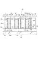
図1には、本発明に係る空調システム10が適用されたサーバ室12が示されている。図示の例では、サーバ室12は、図2に示す建物38の床面12aと天井面12bとの間の空間が、図1に示されているように、一対の縦隔壁14a、14b及び一対の横隔壁14c、14dにより、矩形に区画されて形成されている。このサーバ室12には、望ましくは温度調整された外気処理空気が空気取り入れ口12cを経て取り入れられ、またサーバ室12内の空気は排気口12dを経て排気される。図示の例では、一方の横隔壁14cに排気口12dが設けられ、一方の縦隔壁14dの側に空気取り入れ口12cが設けられている。 FIG. 1 shows a
サーバ室12内には、それぞれ隔壁14a〜14dから間隔をおいて多数のラック16が横隔壁14c、14dに沿って列(18a〜18c)をなし、また該各列が縦隔壁(14a、14b)に沿って相互に間隔をおいて行をなすように、整列して配置されている。図1に示す例では、サーバ室12内の中央部には、一対の横隔壁14c、14dから間隔をおいて一対の縦隔壁14a、14bに平行に中仕切り壁50が配置されている。ラック列18a〜18cは、中仕切り壁50を横切ってその左右に、3列に配列されている。各列は、中仕切り壁50を間に3つのラック16がそれぞれ前面16a及び後面16bの向きを一致させて配列されている。しかも、中仕切り壁50の一方の側(図1で見て中仕切り壁50の左方の側)では、各ラック16は、その後面16bを横隔壁14dに向けて整列する。他方、中仕切り壁50の他方の側(図1で見て中仕切り壁50の右方の側)では、各ラック16は、その前面16aを横隔壁14dに向けて整列する。 In the
各ラック16には、図2に示されているように、従来よく知られたサーバのような情報処理機である電子通信機器20が高さ方向に多段に収容されている。各ラック16の前面16aには、多数の空気吸入口22aが分散して配置されている。また各ラック16の後面16bには、多数の空気排出口22bが分散して配置されている。 As shown in FIG. 2, in each
各ラック16は、前記したように、ラック列毎でそれぞれのラック16の前面16aが一方向に整列するように、しかも中仕切り壁50の一方及び他方の側で相互に反対方向に向くように、配列されている。 As described above, the
各ラック列18a〜18cは、それぞれのラック列18a〜18cに関連して各ラック列を取り巻いて横隔壁14c、14dと平行に設けられる仕切り壁24と共同してサーバ室12の内部を縦方向に分割する。これにより、サーバ室12内は、中仕切り壁50の左右のそれぞれで、4つの区画室26(26a〜26d)に区画されている。すなわち、サーバ室12内は、n列のラック列18及びn列の仕切り壁24により、(n+1)個の区画室26に区画されている。 The
また、図1に示す例では、後述するように、一つのラック列から空気が排出される空間と、このラック列に間隔をおく他の一つのラック列に空気が吸い込まれる空間がサーバ室12の対応する2辺である横隔壁14c、14dでそれぞれ共有されている。この共有された一方の空間(26d)に外気処理空気の取り入れ口12cが設けられ、他方の空間(26a)に排気口12dが設けられている。したがって、図示の例では、空気流46の循環方向に沿って、総計6(n)枚の仕切りにより、第1ないし第6の、計6(n)個の区画室が形成された例と考えることができる。 In the example shown in FIG. 1, as will be described later, the
各仕切り壁24の一方の縦隔壁14aに近接する部分には、隣りあう両区画室間で該両区画室の圧力差を解消するための連通口28が設けられている。連通口28には、空気浄化のためのフィルタや網を設けることができる。また、隣り合う両区画室で圧力差を許容できる場合、相互に両区画室間への逆方向の空気流を可能とすべく回動する可動羽根を連通口28に取り付けることができる。さらに、各仕切り壁24の対応する各隔壁14a及び14bに近接する部分には、図示しないが人の通行を許す開閉扉が設けられている。 In a portion of each
各ラック列(18a〜18c)のラック16の後面16bには、ラック用冷却器30が配置されている。各冷却器30は、図2に示したように、後面16bの空気排出口22bに対向してこれから間隔をおいて配置されるラック用熱交換器30aを備える。ラック用熱交換器として、冷却コイルを有するフィンコイル熱交換器のような熱交換器を適宜採用することができる。 A
各ラック16内の電子通信機器20は、従来よく知られているように、図示しない電源スイッチのオン操作によって作動される通信機器本体(図示せず)を収容する全体に矩形のケーシング20aと、該ケーシングに設けられ、ラック16の空気排出口22bを経て熱交換器30aに対向する排気口20bと、ケーシング20a内に収容された排風機20cとを備える。各排風機20cは、それぞれの前記電源スイッチのオンオフ動作に対応してオンオフ動作させることができるが、後述する「仮想化技術」を制御するサーバ処理プログラムの変更により、サーバの演算量とは無関係にサーバファンが稼働するように、サーバ処理プログラムのロジックが修正される。もっとも、サーバ処理プログラムとは独立してサーバファンを常時稼働するようにファンモータの制御器を付設又は改造しても良い。 As is well known in the art, the
排風機20cが作動すると、各ラック16の空気吸入口22aが開放する各区画室26a〜26dからラック16内に取り入れられた空気は、該ラック内の電子通信機器20から放出される熱を連行して空気排出口22bから対応する熱交換器30aに向けられる。図2に示す例では、ラック用熱交換器30aは、上下に2分割して設置されている。これら熱交換器30aは顕熱冷却器であり、結露を生じないように制御を受ける。 When the
各冷却器30は、図1に示されているように、冷却源機構32に接続されている。冷却源機構32は、例えば冷却塔、冷却水用蓄熱槽あるいは冷凍機のような冷却水源34と、該冷却水源から冷却水の供給を受ける中間熱交換器36とを備える。中間熱交換器36は、図示の例では、各冷却器30に対応して設けられている。また、図1では、図面の簡素化のために、第1のラック列18aのための中間熱交換器36以外の中間熱交換器36が省略されている。 Each cooler 30 is connected to a
各中間熱交換器36には、図3に示すように、図1に示した冷却水源34との間で一次冷却水を循環するための一次冷却水配管40と、対応するラック用熱交換器30aとの間で二次冷却水を循環するための二次冷却水配管42とを備える。両配水管40及び42は、それぞれ往還管からなることは勿論である。各配水管40及び42には、熱媒体である各冷却水の循環のためのポンプ44が設けられている。 As shown in FIG. 3, each
この循環ポンプ44として、図示しないが、相互に並列接続される一対のポンプ44を採用することができる。この一対のポンプ44の採用により、各冷却水の循環について信頼性(冗長性)を高めることができる。ポンプ44は、例えばバレルドモータポンプである。ポンプ44は、作動状態にある電子通信機器20を収容するラック列に対応して設けられた前記熱交換器に前記冷却源機構からの冷媒が供給されるように構成する。例えば、サーバの制御プロブラムで稼働が選択されたサーバ群への運転指令がポンプ44のモータに伝達される。 As this
各中間熱交換器36は、冷却水源34から送られる一次冷却水と各ラック用熱交換器30aから送られる二次冷却水との間で、熱交換を行う。この熱交換によって、各中間熱交換器36とこれに対応するラック用熱交換器30aとを巡る二次冷却水は、該ラック用熱交換器で電子通信機器20から放出される熱を効果的に吸収する。これにより、各ラック16は、対応する冷却器30により、冷却される。 Each
各冷却器30は、対応するラック16内のすべての電子通信機器20からの廃熱を処理するに十分な冷却能力を有するように、設定することが望ましい。例えば各ラック1kWの発熱量あたり15℃の水が、15リットル/分の水量で、上下の各ラック用熱交換器30aに導入される。 Each cooler 30 is desirably set so as to have sufficient cooling capacity to handle waste heat from all the
空気吸込口22aを経て各ラック16内に取り入れられる吸入空気の温度と、該ラックから熱交換器30aを経て排出される排気空気とをほぼ等しくするために、冷却器30の出口に温度センサ(図示せず)が設けられている。前記温度センサの計測値に基づいて、電子通信機器20の排風機20cの回転速度と、各熱交換器30aに設けられた流量調整弁(図示せず)の開度とを制御することが望ましい。すなわち、前記温度センサの検出温度上昇に伴って、排風機20cの回転速度を増大し、前記流量調整弁の開度を増大することが望ましい。 In order to make the temperature of the intake air taken into each
各ラック列(18a〜18c)のラック16は、それぞれの空気吸入口22aが設けられた前面16aを空気取り入れ口12cの側に向け、また空気排出口22bが設けられた後面16bを排気口12dの側に向けて整列して配置されている。また、ラック列(18a〜18c)から下流側に排出される空気流は、ラック列(18a〜18c)毎に設けられた冷却器30の冷却作用によってその上流側の空気温度と同程度に冷却される。なお、空気取り入れ口12cからサーバ室12内に取り入れられる外気処理空気は、図示しない外調機で、例えば22℃、40RHの温湿度に調整される。 The
本発明に係る空調システム10の各冷却器30が作動すると、図1に黒矢印46で示されているように、中仕切り壁50よりも左方の側で、第1のラック列18aから第3のラック列18cへ向けて、第1の区画室26aから第4の区画室26dに向けて、ほぼ均一な温度分布の一方向の空気流46が生じる。 When each cooler 30 of the air-conditioning system 10 according to the present invention is activated, the
したがって、中仕切り壁50よりも左方の側で、各ラック列(18a〜18c)のラック16は、前記した一方向空気流によって、ラック列(18a〜18c)間でむらを生じることなく、すべてのラック16が効果的に冷却される。 Therefore, on the left side of the
第4の区画室26dに向けられた一方向空気流は、空気取り入れ口12cから取り入れられた外気処理空気共に、中仕切り壁50よりも右方の側で、第4のラック列18cから第1のラック列へむけて、第4の区画室26dから排気口12dが開放する第1の区画室26aへ向けて循環する。 The one-way air flow directed to the fourth compartment 26d is the first air flow from the
したがって、サーバ室12内には、図1で見て反時計方向への循環空気流が形成される。また、排気口12dから排出される一部の空気は、空気取り入れ口12cからの外気処理空気で補充される。 Therefore, a circulating air flow is formed in the
また、一部の空気流が、中仕切り壁50よりも右方の側で、連通口28を経て帰還するが、この空気流は、円滑な循環空気流のために、隣合う区画室26(26a〜26d)の気圧差を解消する。すなわち、排風機20cが前記温度センサの計測値に基づいて制御を受ける場合、この排風機20cの稼働状況は、対応するラック16の熱負荷で変動する。したがって、この排風機20cの稼働状況に応じて、隣合う区画室26(26a〜26d)に気圧差が生じることがある。この気圧差は、その高低差の方向によっては、前記した円滑な空気流46を妨げることがあり、滞留のような流れの妨げの原因となることがある。連通口28は、この滞留のような円滑な空気流46の妨げとなる気圧差を解消する作用をなす。 In addition, a part of the air flow returns to the right side of the
本発明に係る前記空調システム10では、前記一方向の空気流46によって各ラック列(18a〜18c)のすべてのラック16を適正に冷却することができる。したがって、床面12aと床スラブ12e(図2参照)との間の床下空間12f(図2参照)にラック冷却用空気路を形成することなく、各ラック16を冷却することができるので、ラック冷却用空気路を不要とする分、床下空間12fの高さを削減することができる。その結果、建物38の高さの増大を回避することができる。 In the air conditioning system 10 according to the present invention, all the
また、冷却源機構32の冷却水源34は、建物38の屋上又は地下室に設置することができるので、建物38のスペースを有効に利用することができ、冷却器30に対応して設けられる中間熱交換器36は、構成が単純であり安価である。さらに、中間熱交換器36は、負荷に応じて個々の熱交換器30aにそれぞれが必要とする冷熱媒体を供給することができ、発熱箇所でそれぞれの発生熱を処理できるので、無駄なく効率的な冷却が可能となる。 Further, since the cooling
さらに、各ラック16に設けられるラック用熱交換器30aには、冷却水源34からの一次冷却水が直接導かれることはなく、対応する各中間熱交換器36との間で、二次冷却水が循環されるに過ぎない。そのため、たとえ冷却水源34と中間熱交換器36との間の一次冷却水配管40に破損が生じても、多量の一次冷却水がサーバ室12内に流入することを防止することができる。また、二次冷却水配管42に破損が生じても、各二次冷却水配管42は独立かつ並列的に配管されているので、ラック16内の電子通信機器20に損傷を与えるほどの多量の冷却水がサーバ室12内に流入することはない。 Furthermore, the primary cooling water from the cooling
また、前記したように、ラック16に従来のような大型の専用ファン装置を設けることなく、各電子通信機器20に内蔵された排風機20cの作動によって、サーバ室12内に適正な循環空気流を形成することができるので、ラック16に大型ファン装置を設けることなく、比較的単純な構成で効果的にラック16を冷却することができる。 Further, as described above, an appropriate circulating air flow can be generated in the
また、図2に示すように、各ラック列(18a〜18c)の最上部に位置するラック16に、該ラックから排出される空気流を下方へ向ける偏向板のような偏向手段16cを設けることができる。各ラック16の空気排出口22bから熱交換器30aに向けて排出される空気流は、温度の高いものほど上昇流を形成する傾向を示すが、偏向手段16cは、この上昇流を下方へ向けることにより、空気流を撹拌する。この撹拌作用によって、ラック16から熱交換器30aに向けて排出される空気流の上下方向での温度分布の均等化を図ることができるので、一層効率的に熱交換器30aを機能させることができる。 Further, as shown in FIG. 2, the
また、同様に、各ラック16の上方に収納された電子通信機器20の排風機20cほどその駆動源の作動速度が漸増するように、ラック16の上段から下段へ向けて各排風機20cの作動速度を漸減することができる。これにより、熱交換器30aに向けて排出される空気流の上下方向での温度分布の均等化を図ることができる。 Similarly, the operation of each
前記したところでは、すべてのラック列18a〜18cのすべてのラック16に収容されたすべての電子通信機器20を作動させた状態について説明したが、各電子通信機器20は、また仮想化技術に従って作動を制御することができる。 In the above description, the state in which all the
本発明への「仮想化技術」の適用では、ポンプの台数制御のように、負荷が100%近いとき、すべてのサーバを稼働させる。また、演算負荷が軽減すると、稼働台数を減らし、その増減をラック列単位で行う。稼働するラック列は、軽負荷の場合、ベース列が常に運転されるというわけではなく、周期的に変更される。 In the application of the “virtualization technology” to the present invention, all servers are operated when the load is close to 100% as in the control of the number of pumps. Further, when the calculation load is reduced, the number of operating units is reduced, and the increase / decrease is performed in units of rack rows. In the case of a light load, the operating rack row is not always operated, but is changed periodically.
この仮想化技術によれば、例えば、中仕切り壁50の左方に位置するラック列18a〜18cを第1ないし第3群(52a〜52c)とし、中仕切り壁50の右方に位置するラック列18a〜18cを第4ないし第6群(52d〜52f)と仮定すると、サーバ処理プロブラムにより、群毎に電子通信機器20の作動のオンオフが制御を受ける。 According to this virtualization technology, for example, the
例えば、第1群52a及び第4群52dの電子通信機器20が作動され、順次作動される電子通信機器20が同数の群が群毎に切り換えられる。このように、仮想化技術によれば、電子通信機器20の運用が群毎に切り換えられる。 For example, the
また、各サーバのファンすなわち電子通信機器20の排風機20cをサーバの演算量とは関係無く稼働させるために、サーバ処理プログラムのロジックが修正される。あるいは、排風機20cに常時給電し、保守などの人為的な演算停止のために強制的に電子通信機器20を停止させる場合を除き、排風機20cの運転を継続するように構成する。なお、データセンタでは、サーバは24時間稼働しており、段落0029で述べたような電源スイッチのオンオフ操作は常態ではない。このような24時間稼働の状態では、電子通信機器20の排風機20cすなわちサーバファンは、排熱のみならず、前記した空気循環の機能を担うために、運転時には最大能力で運転される。また必要に応じて、中間ファンを設けることができる。 In addition, the logic of the server processing program is modified in order to operate the fans of each server, that is, the
本発明の空調システム10は、このような仮想化技術に適用させるべく、例えば、運用中の群(52a〜52f)に対応する熱交換器30aにのみ、二次冷却水が循環するように供給される。したがって、運用中の電子通信機器20に内蔵された排風機20cを作動させ、休止中の電子通信機器20に内蔵された排風機20cの作動を停止することができる。しかしながら、前記した確実な空気循環を実現する上で、運用中か休止中かに拘わらず、すべての電子通信機器20の排風機20cを例えば一定の作動速度で作動させることが望ましい。 The air-conditioning system 10 of the present invention is supplied so that the secondary cooling water circulates only to the
さらに、図示しないが、空調システム10は、各ラック列18a〜18cを一単位として、複数のラック列18a〜18cの単位をサーバ室12内に並列的に配置することができる。 Furthermore, although not illustrated, the air conditioning system 10 can arrange the units of the plurality of
本発明は、上記実施例に限定されず、その趣旨を逸脱しない限り、種々に変更することができる。例えば、仮想化技術以外にも空調システム10を適用することができる。また、各ラックに収容される電子通信機器の発熱量の増大に応じてラック列毎に冷却器の容量を選定することができ、前記電子通信機器の入れ替えに対して柔軟性及び融通性のある空調システムが提供される。また、冷媒として水を利用した空調システムを示したが、圧縮膨張作用による冷却に用いられるフロン系のような冷媒ガスを用いることができる。 The present invention is not limited to the above embodiments, and various modifications can be made without departing from the spirit of the present invention. For example, the air conditioning system 10 can be applied other than the virtualization technology. In addition, the capacity of the cooler can be selected for each rack row in accordance with the increase in the amount of heat generated by the electronic communication equipment accommodated in each rack, and the electronic communication equipment can be replaced with flexibility and flexibility. An air conditioning system is provided. Moreover, although the air-conditioning system using water as a refrigerant | coolant was shown, refrigerant gas like the Freon type | system | group used for cooling by a compression expansion effect | action can be used.
10 空調システム
12 サーバ室(部屋)
16 ラック
16a ラックの前面
16b ラックの後面
18(18a〜18c) ラック列
20 電子通信機器
20a 電子通信機器のケーシング
20b ケーシングの排気口
20c 電子通信機器の排風機
22a ラックの空気吸入口
22b ラックの空気排出口
24 仕切り壁
26(26a〜26d) 区画室
30 冷却器
30a ラック用熱交換器
32 冷却源機構
34 冷却水源
36 中間熱交換器
40 一次冷却水配管
42 二次冷却水配管
46 一方向の空気流
50 中仕切り壁10
16
Claims (7)
Translated fromJapanese前記排風機の作動によって前記空気排出口から排出される空気を冷却すべく、前記ラックの近傍で該ラックの前記空気排出口に対向して配置された熱交換器と、前記熱交換器に冷媒を供給する冷却源機構とを含み、
前記各ラック内を通って前記部屋内を流れる空気が前記排風機の作動によって一方向の流れを形成するように、ラック列毎で該ラック列の前記ラックの向きが一致しかつ互いに隣り合って間隔をおく前記ラック列の前記ラックの向きが一致するように、前記ラック列が配置され、前記熱交換器は、前記ラックからの廃熱による前記部屋内の温度上昇を防止すべく前記熱交換器を経る前記空気を冷却し、前記排風機は前記情報処理機本体の作動の有無に拘わらず、作動されている、空調システム。A casing for housing the information processing unit main body, an exhaust port provided in the casing, and provided in the casing for discharging the amount of heat released from the information processing unit main body through the exhaust port to the outside of the casing A plurality of racks for accommodating a plurality of information processing equipment main bodies arranged in multiple stages, each having an air inlet on the front surface and an air outlet on the rear surface, and the information An air conditioning system for a room in which a rack row is configured by a plurality of racks in which a main body of the processor is stored with each of the exhaust ports facing the air discharge port of the corresponding rack, and the rows are arranged in a plurality of rows Because
A heat exchanger disposed in the vicinity of the rack and facing the air outlet of the rack to cool air discharged from the air outlet by the operation of the exhaust fan, and a refrigerant in the heat exchanger A cooling source mechanism for supplying
The directions of the racks in the rack row are aligned and adjacent to each other so that the air flowing in the room through each rack forms a one-way flow by the operation of the exhaust fan. The rack rows are arranged so that the rack directions of the rack rows that are spaced apart coincide with each other, and the heat exchanger exchanges the heat to prevent temperature rise in the room due to waste heat from the racks. An air conditioning system in which the air passing through a container is cooled, and the exhaust fan is operated regardless of whether or not the information processor main body is operated.
Priority Applications (1)
| Application Number | Priority Date | Filing Date | Title |
|---|---|---|---|
| JP2009238865AJP5283602B2 (en) | 2009-10-16 | 2009-10-16 | Air conditioning system for electronic communication equipment room |
Applications Claiming Priority (1)
| Application Number | Priority Date | Filing Date | Title |
|---|---|---|---|
| JP2009238865AJP5283602B2 (en) | 2009-10-16 | 2009-10-16 | Air conditioning system for electronic communication equipment room |
Publications (2)
| Publication Number | Publication Date |
|---|---|
| JP2011086134Atrue JP2011086134A (en) | 2011-04-28 |
| JP5283602B2 JP5283602B2 (en) | 2013-09-04 |
Family
ID=44079030
Family Applications (1)
| Application Number | Title | Priority Date | Filing Date |
|---|---|---|---|
| JP2009238865AActiveJP5283602B2 (en) | 2009-10-16 | 2009-10-16 | Air conditioning system for electronic communication equipment room |
Country Status (1)
| Country | Link |
|---|---|
| JP (1) | JP5283602B2 (en) |
Cited By (3)
| Publication number | Priority date | Publication date | Assignee | Title |
|---|---|---|---|---|
| WO2013030979A1 (en)* | 2011-08-31 | 2013-03-07 | 富士通株式会社 | Air-conditioning system and heat exchanger |
| JP2013214293A (en)* | 2012-03-08 | 2013-10-17 | Hitachi Ltd | Outside air cooling type and local cooling type information processing system, and load allocation method therefor |
| JP2015114009A (en)* | 2013-12-10 | 2015-06-22 | 高砂熱学工業株式会社 | Air conditioning system for room storing information communication apparatus |
Citations (5)
| Publication number | Priority date | Publication date | Assignee | Title |
|---|---|---|---|---|
| US20050235671A1 (en)* | 2004-04-22 | 2005-10-27 | Belady Christian L | Upgradeable, modular data center cooling apparatus |
| JP2006507676A (en)* | 2002-11-25 | 2006-03-02 | インターナショナル・ビジネス・マシーンズ・コーポレーション | Method and apparatus for composite air liquid cooling of stacked electronics components |
| JP2006208000A (en)* | 2005-01-28 | 2006-08-10 | Hewlett-Packard Development Co Lp | Heat/electric power controller |
| JP2007316989A (en)* | 2006-05-26 | 2007-12-06 | Softbank Idc Corp | Apparatus storage rack and air conditioning system for apparatus storage room |
| JP2010054074A (en)* | 2008-08-26 | 2010-03-11 | Takasago Thermal Eng Co Ltd | Air conditioning system for electronic communication device room or the like |
- 2009
- 2009-10-16JPJP2009238865Apatent/JP5283602B2/enactiveActive
Patent Citations (5)
| Publication number | Priority date | Publication date | Assignee | Title |
|---|---|---|---|---|
| JP2006507676A (en)* | 2002-11-25 | 2006-03-02 | インターナショナル・ビジネス・マシーンズ・コーポレーション | Method and apparatus for composite air liquid cooling of stacked electronics components |
| US20050235671A1 (en)* | 2004-04-22 | 2005-10-27 | Belady Christian L | Upgradeable, modular data center cooling apparatus |
| JP2006208000A (en)* | 2005-01-28 | 2006-08-10 | Hewlett-Packard Development Co Lp | Heat/electric power controller |
| JP2007316989A (en)* | 2006-05-26 | 2007-12-06 | Softbank Idc Corp | Apparatus storage rack and air conditioning system for apparatus storage room |
| JP2010054074A (en)* | 2008-08-26 | 2010-03-11 | Takasago Thermal Eng Co Ltd | Air conditioning system for electronic communication device room or the like |
Cited By (3)
| Publication number | Priority date | Publication date | Assignee | Title |
|---|---|---|---|---|
| WO2013030979A1 (en)* | 2011-08-31 | 2013-03-07 | 富士通株式会社 | Air-conditioning system and heat exchanger |
| JP2013214293A (en)* | 2012-03-08 | 2013-10-17 | Hitachi Ltd | Outside air cooling type and local cooling type information processing system, and load allocation method therefor |
| JP2015114009A (en)* | 2013-12-10 | 2015-06-22 | 高砂熱学工業株式会社 | Air conditioning system for room storing information communication apparatus |
Also Published As
| Publication number | Publication date |
|---|---|
| JP5283602B2 (en) | 2013-09-04 |
Similar Documents
| Publication | Publication Date | Title |
|---|---|---|
| AU2021286252B2 (en) | Data centre cooling system | |
| JP5855895B2 (en) | Air conditioning systems for communication / information processing equipment rooms, etc. | |
| US8266921B2 (en) | Data center | |
| JP5296457B2 (en) | Air conditioning system | |
| JP5717366B2 (en) | Air conditioning system for computer room | |
| JP5524467B2 (en) | Server room air conditioning system | |
| WO2012124723A1 (en) | Outside air utilization air-conditioning system and air-conditioner thereof | |
| CN209749040U (en) | Data center cooling system | |
| JP5669348B2 (en) | Electronic communication equipment room cooling system | |
| JP5390147B2 (en) | Air conditioning system for high-density heat load room | |
| KR102847084B1 (en) | Server rack cooling unit in data center | |
| JP5283453B2 (en) | Air conditioning system for electronic communication equipment room | |
| JP5283602B2 (en) | Air conditioning system for electronic communication equipment room | |
| JP2018066503A (en) | Data center | |
| JP2009127976A (en) | Cooling system | |
| CN203757933U (en) | Hot and cold partition and evaporative cooling and precision air conditioning linkage type unit machine room air conditioning | |
| JP6038702B2 (en) | Air conditioning system | |
| GB2540139A (en) | Evaporative cooler apparatus and method | |
| JP2012122683A (en) | Air conditioner and air conditioning system | |
| JP6673968B2 (en) | Air conditioning system for rooms containing information and communication equipment | |
| JP6447941B2 (en) | Information communication equipment storage room | |
| JP6842074B2 (en) | Air conditioning system in the room that houses information and communication equipment | |
| JP4792122B2 (en) | Data center | |
| JP2024142355A (en) | Radiant air conditioning system | |
| JP2015194280A (en) | Air conditioning system for room storing information communication device |
Legal Events
| Date | Code | Title | Description |
|---|---|---|---|
| A621 | Written request for application examination | Free format text:JAPANESE INTERMEDIATE CODE: A621 Effective date:20120822 | |
| RD03 | Notification of appointment of power of attorney | Free format text:JAPANESE INTERMEDIATE CODE: A7423 Effective date:20130412 | |
| RD04 | Notification of resignation of power of attorney | Free format text:JAPANESE INTERMEDIATE CODE: A7424 Effective date:20130419 | |
| TRDD | Decision of grant or rejection written | ||
| A01 | Written decision to grant a patent or to grant a registration (utility model) | Free format text:JAPANESE INTERMEDIATE CODE: A01 Effective date:20130514 | |
| A977 | Report on retrieval | Free format text:JAPANESE INTERMEDIATE CODE: A971007 Effective date:20130515 | |
| A61 | First payment of annual fees (during grant procedure) | Free format text:JAPANESE INTERMEDIATE CODE: A61 Effective date:20130528 | |
| R150 | Certificate of patent or registration of utility model | Ref document number:5283602 Country of ref document:JP Free format text:JAPANESE INTERMEDIATE CODE: R150 |