JP2011078433A - Analyzer and method for automated diagnosis - Google Patents
Analyzer and method for automated diagnosisDownload PDFInfo
- Publication number
- JP2011078433A JP2011078433AJP2011006319AJP2011006319AJP2011078433AJP 2011078433 AJP2011078433 AJP 2011078433AJP 2011006319 AJP2011006319 AJP 2011006319AJP 2011006319 AJP2011006319 AJP 2011006319AJP 2011078433 AJP2011078433 AJP 2011078433A
- Authority
- JP
- Japan
- Prior art keywords
- mtu
- container
- pipette
- assembly
- incubator
- Prior art date
- Legal status (The legal status is an assumption and is not a legal conclusion. Google has not performed a legal analysis and makes no representation as to the accuracy of the status listed.)
- Withdrawn
Links
- 238000000034methodMethods0.000titleabstractdescription63
- 238000003745diagnosisMethods0.000title1
- 238000006243chemical reactionMethods0.000abstractdescription131
- 238000003556assayMethods0.000abstractdescription117
- 239000003153chemical reaction reagentSubstances0.000abstractdescription111
- 239000012530fluidSubstances0.000abstractdescription109
- 150000007523nucleic acidsChemical class0.000abstractdescription73
- 102000039446nucleic acidsHuman genes0.000abstractdescription67
- 108020004707nucleic acidsProteins0.000abstractdescription67
- 238000003199nucleic acid amplification methodMethods0.000abstractdescription50
- 230000003321amplificationEffects0.000abstractdescription49
- 239000000463materialSubstances0.000abstractdescription35
- 230000008569processEffects0.000abstractdescription21
- 239000000523sampleSubstances0.000description193
- 230000007723transport mechanismEffects0.000description88
- 230000003287optical effectEffects0.000description65
- 230000007246mechanismEffects0.000description53
- 239000002699waste materialSubstances0.000description49
- 238000011534incubationMethods0.000description45
- 238000004140cleaningMethods0.000description43
- 238000007885magnetic separationMethods0.000description42
- 238000012360testing methodMethods0.000description39
- 230000033001locomotionEffects0.000description37
- 238000012545processingMethods0.000description37
- 238000001816coolingMethods0.000description33
- 230000032258transportEffects0.000description33
- 238000005516engineering processMethods0.000description32
- 238000009396hybridizationMethods0.000description26
- 238000001514detection methodMethods0.000description25
- 230000002779inactivationEffects0.000description25
- 239000011534wash bufferSubstances0.000description20
- 238000002156mixingMethods0.000description18
- 238000002360preparation methodMethods0.000description16
- 108091093088AmpliconProteins0.000description14
- 239000000243solutionSubstances0.000description13
- 239000000126substanceSubstances0.000description13
- XLYOFNOQVPJJNP-UHFFFAOYSA-NwaterChemical compoundOXLYOFNOQVPJJNP-UHFFFAOYSA-N0.000description13
- 238000000137annealingMethods0.000description12
- 238000005192partitionMethods0.000description12
- RXNXLAHQOVLMIE-UHFFFAOYSA-Nphenyl 10-methylacridin-10-ium-9-carboxylateChemical compoundC12=CC=CC=C2[N+](C)=C2C=CC=CC2=C1C(=O)OC1=CC=CC=C1RXNXLAHQOVLMIE-UHFFFAOYSA-N0.000description11
- 230000036961partial effectEffects0.000description10
- 108091033319polynucleotideProteins0.000description10
- 102000040430polynucleotideHuman genes0.000description10
- 239000002157polynucleotideSubstances0.000description10
- 229910052782aluminiumInorganic materials0.000description9
- XAGFODPZIPBFFR-UHFFFAOYSA-NaluminiumChemical compound[Al]XAGFODPZIPBFFR-UHFFFAOYSA-N0.000description9
- 239000003990capacitorSubstances0.000description9
- 239000012153distilled waterSubstances0.000description9
- 238000010438heat treatmentMethods0.000description9
- 239000002245particleSubstances0.000description9
- 210000002105tongueAnatomy0.000description9
- 241000700605VirusesSpecies0.000description8
- 239000011888foilSubstances0.000description8
- 238000009413insulationMethods0.000description8
- 239000007787solidSubstances0.000description8
- 238000012546transferMethods0.000description8
- 102000004190EnzymesHuman genes0.000description7
- 108090000790EnzymesProteins0.000description7
- 230000004913activationEffects0.000description7
- 239000012491analyteSubstances0.000description7
- 238000011109contaminationMethods0.000description7
- 230000006870functionEffects0.000description7
- 230000000670limiting effectEffects0.000description7
- 239000006249magnetic particleSubstances0.000description7
- 239000000203mixtureSubstances0.000description7
- 108020004418ribosomal RNAProteins0.000description7
- 238000005406washingMethods0.000description7
- 230000008859changeEffects0.000description6
- 238000004891communicationMethods0.000description6
- 230000014759maintenance of locationEffects0.000description6
- 238000000926separation methodMethods0.000description6
- MHAJPDPJQMAIIY-UHFFFAOYSA-NHydrogen peroxideChemical compoundOOMHAJPDPJQMAIIY-UHFFFAOYSA-N0.000description5
- 239000007844bleaching agentSubstances0.000description5
- 150000001875compoundsChemical class0.000description5
- 238000009826distributionMethods0.000description5
- 238000003780insertionMethods0.000description5
- 230000037431insertionEffects0.000description5
- 239000010808liquid wasteSubstances0.000description5
- 238000012544monitoring processMethods0.000description5
- 239000002773nucleotideSubstances0.000description5
- 125000003729nucleotide groupChemical group0.000description5
- 230000002093peripheral effectEffects0.000description5
- -1polypropylenePolymers0.000description5
- 239000000725suspensionSubstances0.000description5
- 229920002799BoPETPolymers0.000description4
- 108020004414DNAProteins0.000description4
- 102000053602DNAHuman genes0.000description4
- 239000005041Mylar™Substances0.000description4
- 239000004743PolypropyleneSubstances0.000description4
- 238000013019agitationMethods0.000description4
- 210000004027cellAnatomy0.000description4
- 238000010168coupling processMethods0.000description4
- 238000013461designMethods0.000description4
- 238000002405diagnostic procedureMethods0.000description4
- 201000010099diseaseDiseases0.000description4
- 208000037265diseases, disorders, signs and symptomsDiseases0.000description4
- 230000000694effectsEffects0.000description4
- 238000011068loading methodMethods0.000description4
- 239000004033plasticSubstances0.000description4
- 229920003023plasticPolymers0.000description4
- 229920001155polypropylenePolymers0.000description4
- 230000004044responseEffects0.000description4
- 229920002477rna polymerPolymers0.000description4
- 239000002910solid wasteSubstances0.000description4
- 230000003068static effectEffects0.000description4
- 238000007514turningMethods0.000description4
- 108091028043Nucleic acid sequenceProteins0.000description3
- HEMHJVSKTPXQMS-UHFFFAOYSA-MSodium hydroxideChemical compound[OH-].[Na+]HEMHJVSKTPXQMS-UHFFFAOYSA-M0.000description3
- 239000004809TeflonSubstances0.000description3
- 229920006362Teflon®Polymers0.000description3
- 230000015572biosynthetic processEffects0.000description3
- 239000003795chemical substances by applicationSubstances0.000description3
- 230000000295complement effectEffects0.000description3
- 230000008878couplingEffects0.000description3
- 238000005859coupling reactionMethods0.000description3
- 238000012864cross contaminationMethods0.000description3
- 230000009089cytolysisEffects0.000description3
- 238000002347injectionMethods0.000description3
- 239000007924injectionSubstances0.000description3
- 238000007834ligase chain reactionMethods0.000description3
- 239000007788liquidSubstances0.000description3
- 238000003752polymerase chain reactionMethods0.000description3
- 238000011002quantificationMethods0.000description3
- 239000011541reaction mixtureSubstances0.000description3
- 230000002829reductive effectEffects0.000description3
- 230000035945sensitivityEffects0.000description3
- 229920002545silicone oilPolymers0.000description3
- 238000003756stirringMethods0.000description3
- YBJHBAHKTGYVGT-ZKWXMUAHSA-N(+)-BiotinChemical compoundN1C(=O)N[C@@H]2[C@H](CCCCC(=O)O)SC[C@@H]21YBJHBAHKTGYVGT-ZKWXMUAHSA-N0.000description2
- 241000894006BacteriaSpecies0.000description2
- OAKJQQAXSVQMHS-UHFFFAOYSA-NHydrazineChemical compoundNNOAKJQQAXSVQMHS-UHFFFAOYSA-N0.000description2
- PXHVJJICTQNCMI-UHFFFAOYSA-NNickelChemical compound[Ni]PXHVJJICTQNCMI-UHFFFAOYSA-N0.000description2
- 108091034117OligonucleotideProteins0.000description2
- 229910000639Spring steelInorganic materials0.000description2
- 229910000831SteelInorganic materials0.000description2
- 230000005856abnormalityEffects0.000description2
- 239000000443aerosolSubstances0.000description2
- 238000004458analytical methodMethods0.000description2
- 239000000427antigenSubstances0.000description2
- 102000036639antigensHuman genes0.000description2
- 108091007433antigensProteins0.000description2
- 238000013459approachMethods0.000description2
- 239000011324beadSubstances0.000description2
- 230000008901benefitEffects0.000description2
- 210000004369bloodAnatomy0.000description2
- 239000008280bloodSubstances0.000description2
- 230000001413cellular effectEffects0.000description2
- 239000004020conductorSubstances0.000description2
- 238000012790confirmationMethods0.000description2
- 230000009849deactivationEffects0.000description2
- 210000003743erythrocyteAnatomy0.000description2
- 238000005530etchingMethods0.000description2
- 230000002068genetic effectEffects0.000description2
- 229920001519homopolymerPolymers0.000description2
- WQYVRQLZKVEZGA-UHFFFAOYSA-NhypochloriteChemical compoundCl[O-]WQYVRQLZKVEZGA-UHFFFAOYSA-N0.000description2
- 208000015181infectious diseaseDiseases0.000description2
- 230000003993interactionEffects0.000description2
- 238000002372labellingMethods0.000description2
- 210000000265leukocyteAnatomy0.000description2
- 230000013011matingEffects0.000description2
- 238000005259measurementMethods0.000description2
- 108020004999messenger RNAProteins0.000description2
- BDAGIHXWWSANSR-UHFFFAOYSA-Nmethanoic acidNatural productsOC=OBDAGIHXWWSANSR-UHFFFAOYSA-N0.000description2
- 238000012986modificationMethods0.000description2
- 230000004048modificationEffects0.000description2
- 229910001172neodymium magnetInorganic materials0.000description2
- 244000052769pathogenSpecies0.000description2
- 238000011403purification operationMethods0.000description2
- 230000009467reductionEffects0.000description2
- 238000011160researchMethods0.000description2
- 239000004065semiconductorSubstances0.000description2
- 229910001220stainless steelInorganic materials0.000description2
- 239000010935stainless steelSubstances0.000description2
- 239000010959steelSubstances0.000description2
- 238000003860storageMethods0.000description2
- 238000013518transcriptionMethods0.000description2
- 230000035897transcriptionEffects0.000description2
- 238000012795verificationMethods0.000description2
- SIWNEELMSUHJGO-UHFFFAOYSA-N2-(4-bromophenyl)-4,5,6,7-tetrahydro-[1,3]oxazolo[4,5-c]pyridineChemical compoundC1=CC(Br)=CC=C1C(O1)=NC2=C1CCNC2SIWNEELMSUHJGO-UHFFFAOYSA-N0.000description1
- OSWFIVFLDKOXQC-UHFFFAOYSA-N4-(3-methoxyphenyl)anilineChemical compoundCOC1=CC=CC(C=2C=CC(N)=CC=2)=C1OSWFIVFLDKOXQC-UHFFFAOYSA-N0.000description1
- 208000032791BCR-ABL1 positive chronic myelogenous leukemiaDiseases0.000description1
- 208000010833Chronic myeloid leukaemiaDiseases0.000description1
- 206010053567CoagulopathiesDiseases0.000description1
- 229920004943Delrin®Polymers0.000description1
- 241000206602EukaryotaSpecies0.000description1
- VTLYFUHAOXGGBS-UHFFFAOYSA-NFe3+Chemical compound[Fe+3]VTLYFUHAOXGGBS-UHFFFAOYSA-N0.000description1
- 241000233866FungiSpecies0.000description1
- 230000005355Hall effectEffects0.000description1
- 208000033761Myelogenous Chronic BCR-ABL Positive LeukemiaDiseases0.000description1
- 101710163270NucleaseProteins0.000description1
- 238000012408PCR amplificationMethods0.000description1
- 101100502536Phaeodactylum tricornutum FCPC geneProteins0.000description1
- 208000032721Philadelphia ChromosomeDiseases0.000description1
- 239000004698PolyethyleneSubstances0.000description1
- 206010036790Productive coughDiseases0.000description1
- 241000220010RhodeSpecies0.000description1
- 244000191761Sida cordifoliaSpecies0.000description1
- 229920004738ULTEM®Polymers0.000description1
- QJVKUMXDEUEQLH-UHFFFAOYSA-N[B].[Fe].[Nd]Chemical compound[B].[Fe].[Nd]QJVKUMXDEUEQLH-UHFFFAOYSA-N0.000description1
- 230000002159abnormal effectEffects0.000description1
- 238000009825accumulationMethods0.000description1
- DZBUGLKDJFMEHC-UHFFFAOYSA-NacridineChemical classC1=CC=CC2=CC3=CC=CC=C3N=C21DZBUGLKDJFMEHC-UHFFFAOYSA-N0.000description1
- DZBUGLKDJFMEHC-UHFFFAOYSA-Oacridine;hydronChemical compoundC1=CC=CC2=CC3=CC=CC=C3[NH+]=C21DZBUGLKDJFMEHC-UHFFFAOYSA-O0.000description1
- 230000000712assemblyEffects0.000description1
- 238000000429assemblyMethods0.000description1
- 238000005452bendingMethods0.000description1
- 238000004166bioassayMethods0.000description1
- 239000011616biotinSubstances0.000description1
- 229960002685biotinDrugs0.000description1
- 235000020958biotinNutrition0.000description1
- 230000000903blocking effectEffects0.000description1
- 230000006037cell lysisEffects0.000description1
- 239000003638chemical reducing agentSubstances0.000description1
- 230000035602clottingEffects0.000description1
- 239000008139complexing agentSubstances0.000description1
- 239000008367deionised waterSubstances0.000description1
- 229910021641deionized waterInorganic materials0.000description1
- VAYGXNSJCAHWJZ-UHFFFAOYSA-Ndimethyl sulfateChemical compoundCOS(=O)(=O)OCVAYGXNSJCAHWJZ-UHFFFAOYSA-N0.000description1
- 238000006073displacement reactionMethods0.000description1
- 230000009977dual effectEffects0.000description1
- 229920001971elastomerPolymers0.000description1
- 230000002255enzymatic effectEffects0.000description1
- 150000002148estersChemical class0.000description1
- 238000001704evaporationMethods0.000description1
- 230000008020evaporationEffects0.000description1
- 238000000605extractionMethods0.000description1
- 229910001447ferric ionInorganic materials0.000description1
- 238000011049fillingMethods0.000description1
- 238000007667floatingMethods0.000description1
- 239000007850fluorescent dyeSubstances0.000description1
- 235000019253formic acidNutrition0.000description1
- 150000003278haemChemical class0.000description1
- 230000036541healthEffects0.000description1
- 230000017525heat dissipationEffects0.000description1
- 230000020169heat generationEffects0.000description1
- 230000007062hydrolysisEffects0.000description1
- 238000006460hydrolysis reactionMethods0.000description1
- 238000003018immunoassayMethods0.000description1
- 230000000415inactivating effectEffects0.000description1
- 239000003112inhibitorSubstances0.000description1
- 238000007689inspectionMethods0.000description1
- 238000009434installationMethods0.000description1
- 230000002452interceptive effectEffects0.000description1
- 238000002955isolationMethods0.000description1
- 238000003754machiningMethods0.000description1
- 230000005389magnetismEffects0.000description1
- 230000001404mediated effectEffects0.000description1
- 229910052751metalInorganic materials0.000description1
- 239000002184metalSubstances0.000description1
- BRABPYPSZVCCLR-UHFFFAOYSA-NmethopromazineChemical compoundC1=CC=C2N(CCCN(C)C)C3=CC(OC)=CC=C3SC2=C1BRABPYPSZVCCLR-UHFFFAOYSA-N0.000description1
- 229910052759nickelInorganic materials0.000description1
- HYIMSNHJOBLJNT-UHFFFAOYSA-NnifedipineChemical compoundCOC(=O)C1=C(C)NC(C)=C(C(=O)OC)C1C1=CC=CC=C1[N+]([O-])=OHYIMSNHJOBLJNT-UHFFFAOYSA-N0.000description1
- 238000007899nucleic acid hybridizationMethods0.000description1
- 239000007800oxidant agentSubstances0.000description1
- 244000045947parasiteSpecies0.000description1
- 230000001717pathogenic effectEffects0.000description1
- 230000000737periodic effectEffects0.000description1
- 230000002572peristaltic effectEffects0.000description1
- 210000004214philadelphia chromosomeAnatomy0.000description1
- 229920000768polyaminePolymers0.000description1
- 229920000573polyethylenePolymers0.000description1
- 229920000098polyolefinPolymers0.000description1
- 229920002635polyurethanePolymers0.000description1
- 239000004814polyurethaneSubstances0.000description1
- 239000000843powderSubstances0.000description1
- 238000003825pressingMethods0.000description1
- 230000001681protective effectEffects0.000description1
- 238000001243protein synthesisMethods0.000description1
- 102000004169proteins and genesHuman genes0.000description1
- 108090000623proteins and genesProteins0.000description1
- 238000010926purgeMethods0.000description1
- 239000011347resinSubstances0.000description1
- 229920005989resinPolymers0.000description1
- 230000000717retained effectEffects0.000description1
- 230000002441reversible effectEffects0.000description1
- 239000007779soft materialSubstances0.000description1
- 238000011895specific detectionMethods0.000description1
- 210000003802sputumAnatomy0.000description1
- 208000024794sputumDiseases0.000description1
- 239000000758substrateSubstances0.000description1
- 238000003786synthesis reactionMethods0.000description1
- 238000012549trainingMethods0.000description1
- 230000007704transitionEffects0.000description1
- 230000014616translationEffects0.000description1
- 210000002700urineAnatomy0.000description1
- 230000000007visual effectEffects0.000description1
Images


Classifications
- C—CHEMISTRY; METALLURGY
- C12—BIOCHEMISTRY; BEER; SPIRITS; WINE; VINEGAR; MICROBIOLOGY; ENZYMOLOGY; MUTATION OR GENETIC ENGINEERING
- C12Q—MEASURING OR TESTING PROCESSES INVOLVING ENZYMES, NUCLEIC ACIDS OR MICROORGANISMS; COMPOSITIONS OR TEST PAPERS THEREFOR; PROCESSES OF PREPARING SUCH COMPOSITIONS; CONDITION-RESPONSIVE CONTROL IN MICROBIOLOGICAL OR ENZYMOLOGICAL PROCESSES
- C12Q1/00—Measuring or testing processes involving enzymes, nucleic acids or microorganisms; Compositions therefor; Processes of preparing such compositions
- C12Q1/68—Measuring or testing processes involving enzymes, nucleic acids or microorganisms; Compositions therefor; Processes of preparing such compositions involving nucleic acids
- C12Q1/6813—Hybridisation assays
- C12Q1/6834—Enzymatic or biochemical coupling of nucleic acids to a solid phase
- G—PHYSICS
- G01—MEASURING; TESTING
- G01N—INVESTIGATING OR ANALYSING MATERIALS BY DETERMINING THEIR CHEMICAL OR PHYSICAL PROPERTIES
- G01N33/00—Investigating or analysing materials by specific methods not covered by groups G01N1/00 - G01N31/00
- G01N33/48—Biological material, e.g. blood, urine; Haemocytometers
- G01N33/50—Chemical analysis of biological material, e.g. blood, urine; Testing involving biospecific ligand binding methods; Immunological testing
- B—PERFORMING OPERATIONS; TRANSPORTING
- B01—PHYSICAL OR CHEMICAL PROCESSES OR APPARATUS IN GENERAL
- B01F—MIXING, e.g. DISSOLVING, EMULSIFYING OR DISPERSING
- B01F29/00—Mixers with rotating receptacles
- B01F29/10—Mixers with rotating receptacles with receptacles rotated about two different axes, e.g. receptacles having planetary motion
- B—PERFORMING OPERATIONS; TRANSPORTING
- B01—PHYSICAL OR CHEMICAL PROCESSES OR APPARATUS IN GENERAL
- B01F—MIXING, e.g. DISSOLVING, EMULSIFYING OR DISPERSING
- B01F29/00—Mixers with rotating receptacles
- B01F29/30—Mixing the contents of individual packages or containers, e.g. by rotating tins or bottles
- B01F29/32—Containers specially adapted for coupling to rotating frames or the like; Coupling means therefor
- B01F29/322—Containers specially adapted for coupling to rotating frames or the like; Coupling means therefor of two or more containers supported for simultaneous mixing, e.g. for bottles in crates
- B—PERFORMING OPERATIONS; TRANSPORTING
- B01—PHYSICAL OR CHEMICAL PROCESSES OR APPARATUS IN GENERAL
- B01F—MIXING, e.g. DISSOLVING, EMULSIFYING OR DISPERSING
- B01F29/00—Mixers with rotating receptacles
- B01F29/40—Parts or components, e.g. receptacles, feeding or discharging means
- B01F29/403—Disposition of the rotor axis
- B01F29/4035—Disposition of the rotor axis with a receptacle rotating around two or more axes
- B01F29/40354—Disposition of the rotor axis with a receptacle rotating around two or more axes arranged for planetary motion
- B—PERFORMING OPERATIONS; TRANSPORTING
- B01—PHYSICAL OR CHEMICAL PROCESSES OR APPARATUS IN GENERAL
- B01L—CHEMICAL OR PHYSICAL LABORATORY APPARATUS FOR GENERAL USE
- B01L7/00—Heating or cooling apparatus; Heat insulating devices
- B01L7/52—Heating or cooling apparatus; Heat insulating devices with provision for submitting samples to a predetermined sequence of different temperatures, e.g. for treating nucleic acid samples
- B01L7/525—Heating or cooling apparatus; Heat insulating devices with provision for submitting samples to a predetermined sequence of different temperatures, e.g. for treating nucleic acid samples with physical movement of samples between temperature zones
- B01L7/5255—Heating or cooling apparatus; Heat insulating devices with provision for submitting samples to a predetermined sequence of different temperatures, e.g. for treating nucleic acid samples with physical movement of samples between temperature zones by moving sample containers
- B—PERFORMING OPERATIONS; TRANSPORTING
- B03—SEPARATION OF SOLID MATERIALS USING LIQUIDS OR USING PNEUMATIC TABLES OR JIGS; MAGNETIC OR ELECTROSTATIC SEPARATION OF SOLID MATERIALS FROM SOLID MATERIALS OR FLUIDS; SEPARATION BY HIGH-VOLTAGE ELECTRIC FIELDS
- B03C—MAGNETIC OR ELECTROSTATIC SEPARATION OF SOLID MATERIALS FROM SOLID MATERIALS OR FLUIDS; SEPARATION BY HIGH-VOLTAGE ELECTRIC FIELDS
- B03C1/00—Magnetic separation
- B03C1/02—Magnetic separation acting directly on the substance being separated
- B03C1/28—Magnetic plugs and dipsticks
- B03C1/282—Magnetic plugs and dipsticks with associated accumulation indicator, e.g. Hall sensor
- B—PERFORMING OPERATIONS; TRANSPORTING
- B03—SEPARATION OF SOLID MATERIALS USING LIQUIDS OR USING PNEUMATIC TABLES OR JIGS; MAGNETIC OR ELECTROSTATIC SEPARATION OF SOLID MATERIALS FROM SOLID MATERIALS OR FLUIDS; SEPARATION BY HIGH-VOLTAGE ELECTRIC FIELDS
- B03C—MAGNETIC OR ELECTROSTATIC SEPARATION OF SOLID MATERIALS FROM SOLID MATERIALS OR FLUIDS; SEPARATION BY HIGH-VOLTAGE ELECTRIC FIELDS
- B03C1/00—Magnetic separation
- B03C1/02—Magnetic separation acting directly on the substance being separated
- B03C1/28—Magnetic plugs and dipsticks
- B03C1/288—Magnetic plugs and dipsticks disposed at the outer circumference of a recipient
- B—PERFORMING OPERATIONS; TRANSPORTING
- B03—SEPARATION OF SOLID MATERIALS USING LIQUIDS OR USING PNEUMATIC TABLES OR JIGS; MAGNETIC OR ELECTROSTATIC SEPARATION OF SOLID MATERIALS FROM SOLID MATERIALS OR FLUIDS; SEPARATION BY HIGH-VOLTAGE ELECTRIC FIELDS
- B03C—MAGNETIC OR ELECTROSTATIC SEPARATION OF SOLID MATERIALS FROM SOLID MATERIALS OR FLUIDS; SEPARATION BY HIGH-VOLTAGE ELECTRIC FIELDS
- B03C1/00—Magnetic separation
- B03C1/02—Magnetic separation acting directly on the substance being separated
- B03C1/30—Combinations with other devices, not otherwise provided for
- C—CHEMISTRY; METALLURGY
- C12—BIOCHEMISTRY; BEER; SPIRITS; WINE; VINEGAR; MICROBIOLOGY; ENZYMOLOGY; MUTATION OR GENETIC ENGINEERING
- C12Q—MEASURING OR TESTING PROCESSES INVOLVING ENZYMES, NUCLEIC ACIDS OR MICROORGANISMS; COMPOSITIONS OR TEST PAPERS THEREFOR; PROCESSES OF PREPARING SUCH COMPOSITIONS; CONDITION-RESPONSIVE CONTROL IN MICROBIOLOGICAL OR ENZYMOLOGICAL PROCESSES
- C12Q1/00—Measuring or testing processes involving enzymes, nucleic acids or microorganisms; Compositions therefor; Processes of preparing such compositions
- C12Q1/68—Measuring or testing processes involving enzymes, nucleic acids or microorganisms; Compositions therefor; Processes of preparing such compositions involving nucleic acids
- C12Q1/6813—Hybridisation assays
- C12Q1/6832—Enhancement of hybridisation reaction
- G—PHYSICS
- G01—MEASURING; TESTING
- G01N—INVESTIGATING OR ANALYSING MATERIALS BY DETERMINING THEIR CHEMICAL OR PHYSICAL PROPERTIES
- G01N35/00—Automatic analysis not limited to methods or materials provided for in any single one of groups G01N1/00 - G01N33/00; Handling materials therefor
- G01N35/02—Automatic analysis not limited to methods or materials provided for in any single one of groups G01N1/00 - G01N33/00; Handling materials therefor using a plurality of sample containers moved by a conveyor system past one or more treatment or analysis stations
- G01N35/025—Automatic analysis not limited to methods or materials provided for in any single one of groups G01N1/00 - G01N33/00; Handling materials therefor using a plurality of sample containers moved by a conveyor system past one or more treatment or analysis stations having a carousel or turntable for reaction cells or cuvettes
- B—PERFORMING OPERATIONS; TRANSPORTING
- B01—PHYSICAL OR CHEMICAL PROCESSES OR APPARATUS IN GENERAL
- B01L—CHEMICAL OR PHYSICAL LABORATORY APPARATUS FOR GENERAL USE
- B01L2200/00—Solutions for specific problems relating to chemical or physical laboratory apparatus
- B01L2200/14—Process control and prevention of errors
- B01L2200/143—Quality control, feedback systems
- B01L2200/147—Employing temperature sensors
- B—PERFORMING OPERATIONS; TRANSPORTING
- B01—PHYSICAL OR CHEMICAL PROCESSES OR APPARATUS IN GENERAL
- B01L—CHEMICAL OR PHYSICAL LABORATORY APPARATUS FOR GENERAL USE
- B01L2300/00—Additional constructional details
- B01L2300/18—Means for temperature control
- B01L2300/1805—Conductive heating, heat from thermostatted solids is conducted to receptacles, e.g. heating plates, blocks
- B01L2300/1822—Conductive heating, heat from thermostatted solids is conducted to receptacles, e.g. heating plates, blocks using Peltier elements
- B—PERFORMING OPERATIONS; TRANSPORTING
- B01—PHYSICAL OR CHEMICAL PROCESSES OR APPARATUS IN GENERAL
- B01L—CHEMICAL OR PHYSICAL LABORATORY APPARATUS FOR GENERAL USE
- B01L2300/00—Additional constructional details
- B01L2300/18—Means for temperature control
- B01L2300/1805—Conductive heating, heat from thermostatted solids is conducted to receptacles, e.g. heating plates, blocks
- B01L2300/1827—Conductive heating, heat from thermostatted solids is conducted to receptacles, e.g. heating plates, blocks using resistive heater
- B—PERFORMING OPERATIONS; TRANSPORTING
- B01—PHYSICAL OR CHEMICAL PROCESSES OR APPARATUS IN GENERAL
- B01L—CHEMICAL OR PHYSICAL LABORATORY APPARATUS FOR GENERAL USE
- B01L9/00—Supporting devices; Holding devices
- B01L9/06—Test-tube stands; Test-tube holders
- B—PERFORMING OPERATIONS; TRANSPORTING
- B03—SEPARATION OF SOLID MATERIALS USING LIQUIDS OR USING PNEUMATIC TABLES OR JIGS; MAGNETIC OR ELECTROSTATIC SEPARATION OF SOLID MATERIALS FROM SOLID MATERIALS OR FLUIDS; SEPARATION BY HIGH-VOLTAGE ELECTRIC FIELDS
- B03C—MAGNETIC OR ELECTROSTATIC SEPARATION OF SOLID MATERIALS FROM SOLID MATERIALS OR FLUIDS; SEPARATION BY HIGH-VOLTAGE ELECTRIC FIELDS
- B03C2201/00—Details of magnetic or electrostatic separation
- B03C2201/26—Details of magnetic or electrostatic separation for use in medical or biological applications
- C—CHEMISTRY; METALLURGY
- C12—BIOCHEMISTRY; BEER; SPIRITS; WINE; VINEGAR; MICROBIOLOGY; ENZYMOLOGY; MUTATION OR GENETIC ENGINEERING
- C12Q—MEASURING OR TESTING PROCESSES INVOLVING ENZYMES, NUCLEIC ACIDS OR MICROORGANISMS; COMPOSITIONS OR TEST PAPERS THEREFOR; PROCESSES OF PREPARING SUCH COMPOSITIONS; CONDITION-RESPONSIVE CONTROL IN MICROBIOLOGICAL OR ENZYMOLOGICAL PROCESSES
- C12Q2537/00—Reactions characterised by the reaction format or use of a specific feature
- C12Q2537/10—Reactions characterised by the reaction format or use of a specific feature the purpose or use of
- G—PHYSICS
- G01—MEASURING; TESTING
- G01N—INVESTIGATING OR ANALYSING MATERIALS BY DETERMINING THEIR CHEMICAL OR PHYSICAL PROPERTIES
- G01N35/00—Automatic analysis not limited to methods or materials provided for in any single one of groups G01N1/00 - G01N33/00; Handling materials therefor
- G01N2035/00346—Heating or cooling arrangements
- G01N2035/00356—Holding samples at elevated temperature (incubation)
- G—PHYSICS
- G01—MEASURING; TESTING
- G01N—INVESTIGATING OR ANALYSING MATERIALS BY DETERMINING THEIR CHEMICAL OR PHYSICAL PROPERTIES
- G01N35/00—Automatic analysis not limited to methods or materials provided for in any single one of groups G01N1/00 - G01N33/00; Handling materials therefor
- G01N2035/00465—Separating and mixing arrangements
- G01N2035/00524—Mixing by agitating sample carrier
- G—PHYSICS
- G01—MEASURING; TESTING
- G01N—INVESTIGATING OR ANALYSING MATERIALS BY DETERMINING THEIR CHEMICAL OR PHYSICAL PROPERTIES
- G01N35/00—Automatic analysis not limited to methods or materials provided for in any single one of groups G01N1/00 - G01N33/00; Handling materials therefor
- G01N35/02—Automatic analysis not limited to methods or materials provided for in any single one of groups G01N1/00 - G01N33/00; Handling materials therefor using a plurality of sample containers moved by a conveyor system past one or more treatment or analysis stations
- G01N35/04—Details of the conveyor system
- G01N2035/0401—Sample carriers, cuvettes or reaction vessels
- G01N2035/0437—Cleaning cuvettes or reaction vessels
- G—PHYSICS
- G01—MEASURING; TESTING
- G01N—INVESTIGATING OR ANALYSING MATERIALS BY DETERMINING THEIR CHEMICAL OR PHYSICAL PROPERTIES
- G01N35/00—Automatic analysis not limited to methods or materials provided for in any single one of groups G01N1/00 - G01N33/00; Handling materials therefor
- G01N35/02—Automatic analysis not limited to methods or materials provided for in any single one of groups G01N1/00 - G01N33/00; Handling materials therefor using a plurality of sample containers moved by a conveyor system past one or more treatment or analysis stations
- G01N35/04—Details of the conveyor system
- G01N2035/0439—Rotary sample carriers, i.e. carousels
- G01N2035/0453—Multiple carousels working in parallel
- G01N2035/0455—Coaxial carousels
- G—PHYSICS
- G01—MEASURING; TESTING
- G01N—INVESTIGATING OR ANALYSING MATERIALS BY DETERMINING THEIR CHEMICAL OR PHYSICAL PROPERTIES
- G01N35/00—Automatic analysis not limited to methods or materials provided for in any single one of groups G01N1/00 - G01N33/00; Handling materials therefor
- G01N35/10—Devices for transferring samples or any liquids to, in, or from, the analysis apparatus, e.g. suction devices, injection devices
- G01N2035/1027—General features of the devices
- G01N2035/103—General features of the devices using disposable tips
- G—PHYSICS
- G01—MEASURING; TESTING
- G01N—INVESTIGATING OR ANALYSING MATERIALS BY DETERMINING THEIR CHEMICAL OR PHYSICAL PROPERTIES
- G01N35/00—Automatic analysis not limited to methods or materials provided for in any single one of groups G01N1/00 - G01N33/00; Handling materials therefor
- G01N35/0098—Automatic analysis not limited to methods or materials provided for in any single one of groups G01N1/00 - G01N33/00; Handling materials therefor involving analyte bound to insoluble magnetic carrier, e.g. using magnetic separation
- G—PHYSICS
- G01—MEASURING; TESTING
- G01N—INVESTIGATING OR ANALYSING MATERIALS BY DETERMINING THEIR CHEMICAL OR PHYSICAL PROPERTIES
- G01N35/00—Automatic analysis not limited to methods or materials provided for in any single one of groups G01N1/00 - G01N33/00; Handling materials therefor
- G01N35/0099—Automatic analysis not limited to methods or materials provided for in any single one of groups G01N1/00 - G01N33/00; Handling materials therefor comprising robots or similar manipulators
- G—PHYSICS
- G01—MEASURING; TESTING
- G01N—INVESTIGATING OR ANALYSING MATERIALS BY DETERMINING THEIR CHEMICAL OR PHYSICAL PROPERTIES
- G01N35/00—Automatic analysis not limited to methods or materials provided for in any single one of groups G01N1/00 - G01N33/00; Handling materials therefor
- G01N35/10—Devices for transferring samples or any liquids to, in, or from, the analysis apparatus, e.g. suction devices, injection devices
- G01N35/1065—Multiple transfer devices
- Y—GENERAL TAGGING OF NEW TECHNOLOGICAL DEVELOPMENTS; GENERAL TAGGING OF CROSS-SECTIONAL TECHNOLOGIES SPANNING OVER SEVERAL SECTIONS OF THE IPC; TECHNICAL SUBJECTS COVERED BY FORMER USPC CROSS-REFERENCE ART COLLECTIONS [XRACs] AND DIGESTS
- Y10—TECHNICAL SUBJECTS COVERED BY FORMER USPC
- Y10T—TECHNICAL SUBJECTS COVERED BY FORMER US CLASSIFICATION
- Y10T156/00—Adhesive bonding and miscellaneous chemical manufacture
- Y10T156/11—Methods of delaminating, per se; i.e., separating at bonding face
- Y10T156/1105—Delaminating process responsive to feed or shape at delamination
- Y—GENERAL TAGGING OF NEW TECHNOLOGICAL DEVELOPMENTS; GENERAL TAGGING OF CROSS-SECTIONAL TECHNOLOGIES SPANNING OVER SEVERAL SECTIONS OF THE IPC; TECHNICAL SUBJECTS COVERED BY FORMER USPC CROSS-REFERENCE ART COLLECTIONS [XRACs] AND DIGESTS
- Y10—TECHNICAL SUBJECTS COVERED BY FORMER USPC
- Y10T—TECHNICAL SUBJECTS COVERED BY FORMER US CLASSIFICATION
- Y10T156/00—Adhesive bonding and miscellaneous chemical manufacture
- Y10T156/19—Delaminating means
- Y10T156/1906—Delaminating means responsive to feed or shape at delamination
- Y—GENERAL TAGGING OF NEW TECHNOLOGICAL DEVELOPMENTS; GENERAL TAGGING OF CROSS-SECTIONAL TECHNOLOGIES SPANNING OVER SEVERAL SECTIONS OF THE IPC; TECHNICAL SUBJECTS COVERED BY FORMER USPC CROSS-REFERENCE ART COLLECTIONS [XRACs] AND DIGESTS
- Y10—TECHNICAL SUBJECTS COVERED BY FORMER USPC
- Y10T—TECHNICAL SUBJECTS COVERED BY FORMER US CLASSIFICATION
- Y10T29/00—Metal working
- Y10T29/53—Means to assemble or disassemble
- Y10T29/53657—Means to assemble or disassemble to apply or remove a resilient article [e.g., tube, sleeve, etc.]
- Y—GENERAL TAGGING OF NEW TECHNOLOGICAL DEVELOPMENTS; GENERAL TAGGING OF CROSS-SECTIONAL TECHNOLOGIES SPANNING OVER SEVERAL SECTIONS OF THE IPC; TECHNICAL SUBJECTS COVERED BY FORMER USPC CROSS-REFERENCE ART COLLECTIONS [XRACs] AND DIGESTS
- Y10—TECHNICAL SUBJECTS COVERED BY FORMER USPC
- Y10T—TECHNICAL SUBJECTS COVERED BY FORMER US CLASSIFICATION
- Y10T29/00—Metal working
- Y10T29/53—Means to assemble or disassemble
- Y10T29/53683—Spreading parts apart or separating them from face to face engagement
- Y—GENERAL TAGGING OF NEW TECHNOLOGICAL DEVELOPMENTS; GENERAL TAGGING OF CROSS-SECTIONAL TECHNOLOGIES SPANNING OVER SEVERAL SECTIONS OF THE IPC; TECHNICAL SUBJECTS COVERED BY FORMER USPC CROSS-REFERENCE ART COLLECTIONS [XRACs] AND DIGESTS
- Y10—TECHNICAL SUBJECTS COVERED BY FORMER USPC
- Y10T—TECHNICAL SUBJECTS COVERED BY FORMER US CLASSIFICATION
- Y10T29/00—Metal working
- Y10T29/53—Means to assemble or disassemble
- Y10T29/53796—Puller or pusher means, contained force multiplying operator
- Y10T29/53839—Puller or pusher means, contained force multiplying operator having percussion or explosive operator
- Y10T29/53843—Tube, sleeve, or ferrule inserting or removing
- Y—GENERAL TAGGING OF NEW TECHNOLOGICAL DEVELOPMENTS; GENERAL TAGGING OF CROSS-SECTIONAL TECHNOLOGIES SPANNING OVER SEVERAL SECTIONS OF THE IPC; TECHNICAL SUBJECTS COVERED BY FORMER USPC CROSS-REFERENCE ART COLLECTIONS [XRACs] AND DIGESTS
- Y10—TECHNICAL SUBJECTS COVERED BY FORMER USPC
- Y10T—TECHNICAL SUBJECTS COVERED BY FORMER US CLASSIFICATION
- Y10T436/00—Chemistry: analytical and immunological testing
- Y10T436/11—Automated chemical analysis
- Y10T436/111666—Utilizing a centrifuge or compartmented rotor
- Y—GENERAL TAGGING OF NEW TECHNOLOGICAL DEVELOPMENTS; GENERAL TAGGING OF CROSS-SECTIONAL TECHNOLOGIES SPANNING OVER SEVERAL SECTIONS OF THE IPC; TECHNICAL SUBJECTS COVERED BY FORMER USPC CROSS-REFERENCE ART COLLECTIONS [XRACs] AND DIGESTS
- Y10—TECHNICAL SUBJECTS COVERED BY FORMER USPC
- Y10T—TECHNICAL SUBJECTS COVERED BY FORMER US CLASSIFICATION
- Y10T436/00—Chemistry: analytical and immunological testing
- Y10T436/11—Automated chemical analysis
- Y10T436/113332—Automated chemical analysis with conveyance of sample along a test line in a container or rack
- Y10T436/114998—Automated chemical analysis with conveyance of sample along a test line in a container or rack with treatment or replacement of aspirator element [e.g., cleaning, etc.]
- Y—GENERAL TAGGING OF NEW TECHNOLOGICAL DEVELOPMENTS; GENERAL TAGGING OF CROSS-SECTIONAL TECHNOLOGIES SPANNING OVER SEVERAL SECTIONS OF THE IPC; TECHNICAL SUBJECTS COVERED BY FORMER USPC CROSS-REFERENCE ART COLLECTIONS [XRACs] AND DIGESTS
- Y10—TECHNICAL SUBJECTS COVERED BY FORMER USPC
- Y10T—TECHNICAL SUBJECTS COVERED BY FORMER US CLASSIFICATION
- Y10T436/00—Chemistry: analytical and immunological testing
- Y10T436/11—Automated chemical analysis
- Y10T436/119163—Automated chemical analysis with aspirator of claimed structure
- Y—GENERAL TAGGING OF NEW TECHNOLOGICAL DEVELOPMENTS; GENERAL TAGGING OF CROSS-SECTIONAL TECHNOLOGIES SPANNING OVER SEVERAL SECTIONS OF THE IPC; TECHNICAL SUBJECTS COVERED BY FORMER USPC CROSS-REFERENCE ART COLLECTIONS [XRACs] AND DIGESTS
- Y10—TECHNICAL SUBJECTS COVERED BY FORMER USPC
- Y10T—TECHNICAL SUBJECTS COVERED BY FORMER US CLASSIFICATION
- Y10T436/00—Chemistry: analytical and immunological testing
- Y10T436/25—Chemistry: analytical and immunological testing including sample preparation
- Y10T436/2575—Volumetric liquid transfer
Landscapes
- Chemical & Material Sciences (AREA)
- Health & Medical Sciences (AREA)
- Life Sciences & Earth Sciences (AREA)
- Chemical Kinetics & Catalysis (AREA)
- General Health & Medical Sciences (AREA)
- Biochemistry (AREA)
- Organic Chemistry (AREA)
- Engineering & Computer Science (AREA)
- Molecular Biology (AREA)
- Analytical Chemistry (AREA)
- Immunology (AREA)
- Proteomics, Peptides & Aminoacids (AREA)
- Wood Science & Technology (AREA)
- Zoology (AREA)
- Physics & Mathematics (AREA)
- Microbiology (AREA)
- Biotechnology (AREA)
- Clinical Laboratory Science (AREA)
- Biophysics (AREA)
- Bioinformatics & Cheminformatics (AREA)
- General Engineering & Computer Science (AREA)
- Genetics & Genomics (AREA)
- General Physics & Mathematics (AREA)
- Pathology (AREA)
- Biomedical Technology (AREA)
- Hematology (AREA)
- Urology & Nephrology (AREA)
- Food Science & Technology (AREA)
- Medicinal Chemistry (AREA)
- Cell Biology (AREA)
- Automatic Analysis And Handling Materials Therefor (AREA)
- Apparatus Associated With Microorganisms And Enzymes (AREA)
- Measuring Or Testing Involving Enzymes Or Micro-Organisms (AREA)
- Investigating Or Analysing Materials By The Use Of Chemical Reactions (AREA)
- Mixers Of The Rotary Stirring Type (AREA)
- Saccharide Compounds (AREA)
- Investigating Or Analysing Biological Materials (AREA)
- Mixers With Rotating Receptacles And Mixers With Vibration Mechanisms (AREA)
- Spectrometry And Color Measurement (AREA)
- Ultra Sonic Daignosis Equipment (AREA)
Abstract
Description
Translated fromJapanese (1.発明の分野)
本発明は、複数診断アッセイを同時に行うための自動化分析器に関する。(1. Field of the Invention)
The present invention relates to an automated analyzer for performing multiple diagnostic assays simultaneously.
(2.発明の背景)
本明細書中に記載または参照される文献はいずれも本発明の特許請求の範囲の先行技術とはならないと認められる。(2. Background of the Invention)
None of the documents described or referred to in this specification shall be admitted to be prior art to the claims of the present invention.
診断アッセイは、医療診断および健康科学調査において広く使用され、生物的抗原、細胞異常、疾病状態、ならびに宿主生物またはサンプルに存在する寄生虫、菌類、バクテリアおよびウイルスを含む、疾病に関連する病原を検出し、あるいは存在または量を定量化する。診断アッセイが定量化を可能にする場合、医者は、感染または疾病の程度をよりよく算定し得、経時の疾病状態を決定し得る。一般に、診断アッセイは、対象の生物またはウイルスに属する、抗原(イムノアッセイ)または核酸(核酸に基づくアッセイ)の検出のいずれかに基づく。 Diagnostic assays are widely used in medical diagnostics and health science research to detect biological pathogens associated with diseases, including biological antigens, cellular abnormalities, disease states, and parasites, fungi, bacteria and viruses present in host organisms or samples. Detect or quantify presence or amount. If the diagnostic assay allows quantification, the physician can better estimate the extent of the infection or disease and determine the disease state over time. In general, diagnostic assays are based either on the detection of antigens (immunoassays) or nucleic acids (nucleic acid based assays) belonging to the organism or virus of interest.
核酸に基づくアッセイは一般に、対象の生物またはウイルスに特異的である、サンプル中の1つ以上の標的核酸配列の検出または定量化に導く、いくつかの工程を含む。この標的核酸配列は、生物またはウイルスの識別可能な群にも特異的であり得、ここでこの群は、群の全てのメンバーに共通し、アッセイされるサンプルにおいてその群に特異的である核酸の少なくとも1つの、共通する配列により規定される。核酸に基づく方法を使用した生物およびウイルスの個体および群の検出は、Kohneによる、米国特許第4,851,330号およびHogan米国特許第5,541,551号に詳しく記載される。 Nucleic acid based assays generally involve several steps that lead to the detection or quantification of one or more target nucleic acid sequences in a sample that are specific for the organism or virus of interest. The target nucleic acid sequence can also be specific to an identifiable group of organisms or viruses, where the group is common to all members of the group and is nucleic acid that is specific to that group in the sample being assayed. Defined by at least one common sequence. Detection of organisms and virus individuals and groups using nucleic acid based methods is described in detail in US Pat. No. 4,851,330 and Hogan US Pat. No. 5,541,551 by Kohne.
核酸に基づくアッセイの第一工程は、対象の生物またはウイルスに属する核酸配列に対して、ストリンジェントなハイブリダイゼーション条件のもとで、特異性を示すプローブを設計することである。核酸に基づくアッセイは、デオキシリボ核酸(DNA)またはリボ核酸(RNA)のいずれかを検出するために設計され得るが、リボソームRNA(rRNA)、または遺伝子コード化rRNA(rDNA)は、典型的にはサンプル中の原核生物または真核生物の検出のための好適な核酸である。リボソームRNA標的配列は、細胞内に比較的豊富にあるため、そしてrRNAは、近接して関連する生物の間でさえ識別し得るプローブを設計するのに利用され得る配列可変性の領域を含むため、好適である。(リボソームRNAは、リボソームの主要な構造の構成要素であり、細胞中の蛋白合成の部位である。)ウイルス(rRNAを含まない)および細胞変化はしばしば標的化DNA、RNA、または蛋白を合成するために使用される核酸媒介物である、メッセンジャーRNA(mRNA)配列により、最もよく検出される。核酸に基づくアッセイの焦点が遺伝的異常の検出であるとき、慢性骨髄性白血病に伴う異常なフィラデルフィア染色体などの、遺伝情報の識別可能な変化を検出するために、プローブは通常設計される。例えばStephensonら米国特許第4,681,840号を参照のこと。 The first step in a nucleic acid-based assay is to design a probe that exhibits specificity under stringent hybridization conditions for nucleic acid sequences belonging to the organism or virus of interest. While nucleic acid based assays can be designed to detect either deoxyribonucleic acid (DNA) or ribonucleic acid (RNA), ribosomal RNA (rRNA), or gene-encoded rRNA (rDNA), typically A suitable nucleic acid for the detection of prokaryotes or eukaryotes in a sample. Because ribosomal RNA target sequences are relatively abundant in cells, and rRNA contains sequence-variable regions that can be used to design probes that can be discriminated even between closely related organisms. Is preferable. (Ribosomal RNA is a major structural component of the ribosome and is the site of protein synthesis in the cell.) Viruses (not including rRNA) and cellular changes often synthesize targeted DNA, RNA, or protein. It is best detected by the messenger RNA (mRNA) sequence, which is the nucleic acid mediator used. When the focus of nucleic acid based assays is detection of genetic abnormalities, probes are usually designed to detect identifiable changes in genetic information, such as abnormal Philadelphia chromosomes associated with chronic myelogenous leukemia. See, for example, Stephenson et al. US Pat. No. 4,681,840.
核酸に基づくアッセイを行うとき、サンプルの調製は、サンプル中に存在し得る標的核酸を遊離し、安定化させるために必要である。サンプル調製はまた、ヌクレアーゼ活性の除去のために作用し得、そして核酸増幅(以下に記載)または標的核酸の検出の潜在的インヒビターの除去または不活性化にも作用し得る。例えば、Ryderらの米国特許第5,639,599号を参照のこと、この特許は、溶解赤血球により寄与される第二鉄イオンと錯体化し得る錯化剤の使用を含んだ、増幅のための核酸の調整のための方法を開示する。サンプル調製の方法は、変化し得、処理されるサンプル(例えば血液、尿、便、膿、痰)の性質に一部に依存する。標的核酸が、希釈されたまたは希釈されない全血サンプル中に存在する白血球集団から抽出されているとき、差示的溶解手順が一般的に続く。Ryderらの欧州特許出願第93304542.9号および欧州特許公報第0547267号を参照のこと。差示的溶解手順は、当業者には周知であり、白血球から核酸を特定的に単離するために設計され、一方で、核酸増幅または検出に干渉し得るヘムなどの赤血球産物の存在または活性を制限または除去する。 When performing nucleic acid based assays, sample preparation is necessary to release and stabilize target nucleic acids that may be present in the sample. Sample preparation can also act for removal of nuclease activity and can also act for removal or inactivation of potential inhibitors of nucleic acid amplification (described below) or detection of target nucleic acids. See, for example, Ryder et al., US Pat. No. 5,639,599, which includes the use of complexing agents that can complex with ferric ions contributed by lysed erythrocytes. Disclosed are methods for the preparation of nucleic acids. The method of sample preparation can vary and depends in part on the nature of the sample being processed (eg, blood, urine, stool, pus, sputum). A differential lysis procedure is generally followed when the target nucleic acid is being extracted from a leukocyte population present in a diluted or undiluted whole blood sample. See Ryder et al., European Patent Application No. 933044542.9 and European Patent Publication No. 0547267. Differential lysis procedures are well known to those skilled in the art and are designed to specifically isolate nucleic acids from leukocytes while the presence or activity of erythrocyte products such as heme that can interfere with nucleic acid amplification or detection. Restrict or eliminate.
抽出された核酸をプローブに晒す前または後に、標的核酸は、磁気ビーズなどの基質へ結合される「捕捉プローブ」を使用して、直接的にまたは間接的に、のいずれかで、標的捕捉手段によって固定化され得る。標的−捕捉法の例は、Rankiらによる米国特許第4,486,539号およびStabinskyによる米国特許第4,751,177号に記載される。標的捕捉プローブは、一般にストリンジェントなハイブリダイゼーション条件のもとで標的配列もまた含む核酸の配列と、ハイブリダイズし得る、核酸の短い配列(すなわちオリゴヌクレオチド)である。反応受容器に近接して磁石が使用され、磁気ビーズを受容器の側部に引き寄せ保持する。一旦、標的核酸がこのように固定化されると、ハイブリダイズされた核酸は、反応受容器から流体を吸引すること、そして必要に応じて1つ以上の洗浄工程を行うことにより、ハイブリダイズされていない核酸から、分離され得る。 Before or after exposing the extracted nucleic acid to the probe, the target nucleic acid, either directly or indirectly, using a “capture probe” that is bound to a substrate such as a magnetic bead Can be immobilized by. Examples of target-capture methods are described in US Pat. No. 4,486,539 by Ranki et al. And US Pat. No. 4,751,177 by Stabinsky. A target capture probe is a short sequence of nucleic acid (ie, an oligonucleotide) that can hybridize with a sequence of nucleic acid that also includes a target sequence, generally under stringent hybridization conditions. A magnet is used in close proximity to the reaction receptor to attract and hold the magnetic beads to the sides of the receptor. Once the target nucleic acid is so immobilized, the hybridized nucleic acid is hybridized by aspirating the fluid from the reaction receptor and optionally performing one or more washing steps. It can be separated from non-nucleic acid.
たいていの場合、当業者に周知のいくつかの核酸増幅手順のうちの任意を使用して標的配列を増幅することが望ましい。特定的には、核酸増幅は増幅される核酸配列に相補的な配列を含む、核酸アンプリコン(コピー)の酵素的合成である。この技術において実施される核酸増幅手順の例は、ポリメラーゼ連鎖反応(PCR)、鎖置換増幅(SDA)、リガーゼ連鎖反応(LCR)および転写付随増幅(TAA)を含む。核酸増幅は、サンプル中に存在する標的配列の量が非常に低いとき特に有用である。標的配列を増幅し、そして合成されるアンプリコンを検出することにより、アッセイの感度が非常に改善される。これは、対象の生物またはウイルスに属するサンプル中の核酸の検出をより確実にするために、アッセイの開始において標的配列がほとんど必要とされないからである。 In most cases, it is desirable to amplify the target sequence using any of several nucleic acid amplification procedures well known to those skilled in the art. Specifically, nucleic acid amplification is the enzymatic synthesis of a nucleic acid amplicon (copy) that contains a sequence that is complementary to the nucleic acid sequence to be amplified. Examples of nucleic acid amplification procedures performed in this technology include polymerase chain reaction (PCR), strand displacement amplification (SDA), ligase chain reaction (LCR) and transcription-associated amplification (TAA). Nucleic acid amplification is particularly useful when the amount of target sequence present in the sample is very low. By amplifying the target sequence and detecting the amplicon synthesized, the sensitivity of the assay is greatly improved. This is because very little target sequence is required at the start of the assay to more reliably detect nucleic acids in samples belonging to the organism or virus of interest.
核酸増幅の方法は、文献中に徹底して記載されている。例えば、PCR増幅は、Mullisらの米国特許第4,683,195号、4,683,202号および4,800,159号に、ならびにMethods in Enzymology、155:335−350(1987)に記載される。SDAの例は、WalkerのPCR Methods and Applications,3:25−30(1993)、WalkerらのNucleic Acids Res.,20:1691−1996(1992)およびProc.Natl.Acad.Sci.,89:392−396(1991)に見出
され得る。LCRは、米国特許第5,427,930号および第5,686,272号に記載される。種々のTAAフォーマットは、Burgらの米国特許第5,437,990号;Kacianらの米国特許第5,399,491号および5,554,516号;ならびにGingerasらの国際出願PCT/US87/01966と国際公報WO88/01302および国際出願PCT/US88/02108と国際公報WO88/10315などの発行物に提供される。Nucleic acid amplification methods are thoroughly described in the literature. For example, PCR amplification is described in US Pat. Nos. 4,683,195, 4,683,202 and 4,800,159 to Mullis et al., And Methods in Enzymology, 155: 335-350 (1987). The Examples of SDA can be found in Walker's PCR Methods and Applications, 3: 25-30 (1993), Walker et al., Nucleic Acids Res. 20: 1691-1996 (1992) and Proc. Natl. Acad. Sci. 89: 392-396 (1991). LCR is described in US Pat. Nos. 5,427,930 and 5,686,272. Various TAA formats are described in Burg et al. US Pat. No. 5,437,990; Kacian et al. US Pat. Nos. 5,399,491 and 5,554,516; and Gingeras et al. International Application PCT / US87 / 01966. And international publications WO88 / 01302 and international applications PCT / US88 / 02108 and international publications WO88 / 10315.
標的核酸配列の検出は、標的配列またはそのアンプリコンに対して実質的に相補的なヌクレオチド塩基配列を有するプローブの使用を要求する。選択されるアッセイ条件のもとで、サンプル中の標的配列の存在を医者が検出することを可能にする様式で、プローブは標的配列またはそのアンプリコンにハイブリダイズする。効果的なプローブは、標的配列の存在の検出に干渉する核酸配列との非特異的ハイブリダイゼーションを防ぐように設計される。プローブは検出を可能にする標識を含み得、この標識は、例えば、放射標識、蛍光色素、ビオチン、酵素または化学発光化合物である。化学発光化合物は、ハイブリダイゼーション保護アッセイ(HPA)において使用され、次いで照度計にて検出され得るアクリジニウムエステルを含む。化学発光化合物および化学発光化合物でのプローブ標識の方法例は、Arnoldらの米国特許第4,950,613号、第5,185,439号および第5,585,481号;およびCampbellらの米国特許第4,946,958号に見い出され得る。 Detection of a target nucleic acid sequence requires the use of a probe having a nucleotide base sequence that is substantially complementary to the target sequence or its amplicon. Under selected assay conditions, the probe hybridizes to the target sequence or its amplicon in a manner that allows the physician to detect the presence of the target sequence in the sample. Effective probes are designed to prevent non-specific hybridization with nucleic acid sequences that interfere with detection of the presence of the target sequence. The probe may include a label that allows detection, such as a radiolabel, a fluorescent dye, biotin, an enzyme, or a chemiluminescent compound. Chemiluminescent compounds include acridinium esters that can be used in hybridization protection assays (HPA) and then detected with a luminometer. Examples of chemiluminescent compounds and methods of probe labeling with chemiluminescent compounds are described in Arnold et al. US Pat. Nos. 4,950,613, 5,185,439 and 5,585,481; and Campbell et al. US It can be found in patent 4,946,958.
HPAは、標的配列またはそのアンプリコンへハイブリダイゼーションされた、アクリジニウムエステル−標識プローブの特異的な検出を可能にする差示的加水分解に基づく検出方法である。HPAは、Arnoldらによって米国特許第5,283,174号および第5,639,599号に詳細に記載される。この検出フォーマットは、溶液中でハイブリダイズされたプローブが、非ハイブリダイズプローブから識別されることを可能とし、そしてハイブリダイゼーション工程と選択工程の両方を含む。ハイブリダイゼーション工程において、アクリジニウムエステル標識プローブの余剰が、反応受容器に加えられ、標的配列またはそのアンプリコンにアニールすることが可能にされる。ハイブリダイゼーション工程に次いで、ハイブリダイズされていないプローブに伴う標識が、アルカリ性の試薬の添加による選択工程において、非化学発光的に行われる。このアルカリ試薬は、ハイブリダイズされないプローブに伴うアクリジニウムエステル標識のみを特異的に加水分解し、プローブと標的とのハイブリッドのアクリジニウムエステルを非処置および検出可能のままとする。ハイブリダイズされたプローブのアクリジニウムエステルからの化学発光は、次いで照度計を使用して測定され得、そして信号は相対光単位(RLU)で表される。 HPA is a detection method based on differential hydrolysis that allows specific detection of an acridinium ester-labeled probe hybridized to a target sequence or its amplicon. HPA is described in detail in US Pat. Nos. 5,283,174 and 5,639,599 by Arnold et al. This detection format allows probes hybridized in solution to be distinguished from non-hybridized probes and includes both a hybridization step and a selection step. In the hybridization step, a surplus of acridinium ester labeled probe is added to the reaction receptor, allowing it to anneal to the target sequence or its amplicon. Subsequent to the hybridization step, labeling with unhybridized probes is performed non-chemiluminescently in a selection step by addition of an alkaline reagent. This alkaline reagent specifically hydrolyzes only the acridinium ester label associated with the unhybridized probe, leaving the probe and target hybrid acridinium ester untreated and detectable. Chemiluminescence from the acridinium ester of the hybridized probe can then be measured using a luminometer and the signal is expressed in relative light units (RLU).
核酸に基づくアッセイが動作する後、そして続く増幅反応の可能性のある汚染を避けるため、反応混合物は、反応受容器中の核酸および関連する増幅産物を破壊する不活性化試薬で処理され得る。そのような試薬には、酸化剤、還元剤、および核酸の一次化学構造を改変する反応性化学薬品が含まれ得る。これらの試薬は、核酸がRNAであろうとDNAであろうと、その核酸を増幅反応に対して不活性にさせることにより作用する。そのような化学試薬の例には、次亜塩素酸塩(漂白剤)の溶液、過マンガン酸カルシウムの溶液、ギ酸、ヒドラジン、硫酸ジメチル、および類似の化合物が含まれ得る。不活性化プロトコルのより詳細は、Dattaguptaらの米国特許第5,612,200号に見い出され得る。 After the nucleic acid based assay is run and to avoid possible contamination of subsequent amplification reactions, the reaction mixture can be treated with an inactivation reagent that destroys the nucleic acids and associated amplification products in the reaction receptor. Such reagents can include oxidizing agents, reducing agents, and reactive chemicals that alter the primary chemical structure of the nucleic acid. These reagents, whether the nucleic acid is RNA or DNA, act by making the nucleic acid inactive to the amplification reaction. Examples of such chemical reagents may include hypochlorite (bleach) solutions, calcium permanganate solutions, formic acid, hydrazine, dimethyl sulfate, and similar compounds. More details of the inactivation protocol can be found in US Pat. No. 5,612,200 to Dattagupta et al.
手作業で行うとき、核酸に基づくアッセイに関する複雑さとかなりの数の処理工程は、医者の間違いの機会、病原への曝露、およびアッセイ中の相互汚染を導びく。手作業のフォーマットに続いて、医者は試験サンプル、試薬、廃棄コンテナ、アッセイ受容器、ピペットチップ部、吸引装置、分配装置、および標的捕捉を行うための磁気ラックを安全にそして都合よく並置しなければならず、一方ラック、試験サンプル、アッセイ受容器、および関連するチップを混同しないように特に注意し、または試験管、チップ、受容器もしくは器具をひっくり返すことがないように特に注意しなければならない。加えて、医者は、アッセイ受容器間の所望しない接触、エアロゾルの形成、または標的捕捉アッセイに使用される磁気粒子もしくは他の物質の吸引を避けるための正確な遂行が要求される態様で、携帯、非固定器具で、吸引および分配工程を注意深く実行しなければならない。さらなる用心として、手作業で行われる標的捕捉アッセイ中の磁界は、しばしばアッセイ受容器の一方側のみに適用され、アッセイ受容器の反対側に沿って挿入されたピペットチップを通して流体が吸引され得るようにされる。磁界をアッセイ受容器の一方側のみに適用することは、標的捕捉アッセイを行うためのあまり効率がよくない手段であるが、医者の不正確さの結果として、磁気粒子が不必要に吸引されることを防ぐために設計される。 When performed manually, the complexity and significant number of processing steps associated with nucleic acid-based assays lead to opportunities for physician error, exposure to pathogens, and cross-contamination during the assay. Following the manual format, the physician must safely and conveniently juxtapose test samples, reagents, waste containers, assay receivers, pipette tips, aspirators, dispensing devices, and magnetic racks for target capture. On the other hand, special care must be taken not to confuse the rack, test sample, assay receiver, and associated tips, or special care should be taken not to overturn the test tube, tip, receptor or instrument. . In addition, physicians are able to carry in a manner that requires precise performance to avoid unwanted contact between assay receptors, aerosol formation, or inhalation of magnetic particles or other materials used in target capture assays. With a non-fixed instrument, the suction and dispensing process must be performed carefully. As a further precaution, the magnetic field in a manually performed target capture assay is often applied only to one side of the assay receptor so that fluid can be aspirated through a pipette tip inserted along the opposite side of the assay receptor. To be. Applying a magnetic field to only one side of the assay receptor is a less efficient means for performing a target capture assay, but as a result of physician inaccuracy, magnetic particles are unnecessarily attracted Designed to prevent that.
核酸に基づくアッセイを行うための手作業のアプローチに関する、多くの注意が処理される自動化診断分析器の必要が存在する。特に、核酸に基づくアッセイの多様な処理工程を自動化することによって、かなりの利点が実現され得、これらの利点には、使用者の間違いのリスク、病原曝露、汚染、および流出を多いに減少させることが含まれ、一方でスループット容量のかなりの増加という利点が含まれる。核酸に基づくアッセイの工程の自動化はまた医者が必要とする訓練の量を減少させ、そして大容量手作業適用に起因する肉体的損傷の原因を実質的に除去する。 There is a need for automated diagnostic analyzers that handle a lot of attention regarding manual approaches to conducting nucleic acid based assays. In particular, significant benefits can be realized by automating the various processing steps of nucleic acid-based assays, which greatly reduce the risk of user error, pathogenic exposure, contamination, and spillage. While the advantage of a significant increase in throughput capacity. Automation of the nucleic acid based assay process also reduces the amount of training required by the physician and substantially eliminates the cause of physical damage resulting from high volume manual application.
(発明の要旨)
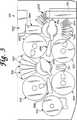
上記の必要性は、本発明の局面に従って構成されそして操作された自動臨床分析器により、表される。一般に自動化臨床分析器は、反応受容器に含まれる複数の反応混合物の1つ以上のアッセイを行う際に含まれる、多様な自動化されたステーションまたはモジュールの操作を統合または組み合わせる。この分析器は好ましくは、自給型の独立ユニットである。アッセイ標本材料および反応受容器、および種々の溶液、試薬、およびアッセイを行うのに使用される他の材料は、好ましくは分析器内に格納され、アッセイを行うときに生成される廃棄産物も同様である。(Summary of the Invention)
The above need is represented by an automated clinical analyzer constructed and operated in accordance with aspects of the present invention. In general, an automated clinical analyzer integrates or combines the operations of various automated stations or modules involved in performing one or more assays of a plurality of reaction mixtures contained in a reaction receptor. This analyzer is preferably a self-contained independent unit. Assay specimen materials and reaction receptors, and various solutions, reagents, and other materials used to perform the assay are preferably stored in the analyzer, as well as the waste products generated when performing the assay. It is.
この分析器は、分析器制御およびアッセイスケジュールソフトウェアを動作させるコンピュータコントローラを含み、このコンピュータコントローラは、分析器のステーションの操作、および分析器を通る各反応受容器の移動を調整する。 The analyzer includes a computer controller that runs analyzer control and assay schedule software, which coordinates the operation of the analyzer station and the movement of each reaction receptor through the analyzer.
反応受容器は、運搬機構により回収されるピックアップ位置にて各受容器を順次提供する入力列に充填され得、この運搬機構は自動的に分析器のステーションの間で反応受容器を移動させる。 The reaction receivers can be filled into an input train that in turn provides each receptor at a pick-up position that is retrieved by the transport mechanism, which automatically moves the reaction receptor between analyzer stations.
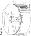
標本コンテナが第一リングアセンブリ上で運ばれ、そして使い捨てピペットチップが第二リングアセンブリ上で運ばれる。固体支持材料の懸濁液を含む標的捕捉試薬のコンテナは、内部回転可能アセンブリ上に運ばれる。この内部回転可能アセンブリは、コンテナを選択的に揺動するかまたは自動ロボットピペットシステムのプローブによりアクセスするためのコンテナを提供するために、構成されるかまたは配置される。液体標本材料および標的捕捉試薬を含む反応混合物は、各反応受容器内のピペットシステムにより調製される。 A specimen container is carried on the first ring assembly and a disposable pipette tip is carried on the second ring assembly. A container of target capture reagent containing a suspension of solid support material is carried on an internal rotatable assembly. This internal rotatable assembly is configured or arranged to provide a container for selectively rocking the container or for access by a probe of an automated robotic pipette system. A reaction mixture containing liquid specimen material and target capture reagent is prepared by a pipette system in each reaction receptor.
この分析器はさらに、そこに配置される受容器の内容物を混合するための受容器ミキサを含む。このミキサは、液体コンテナと流体連絡し得、受容器中へ1以上の流体を分配するための分配器を含み得る。1つ以上のインキュベータが温度制御チャンバ内に複数の受容器を備え、個々の容器はこのチャンバ内に自動的に配置され、そしてこのチャンバから自動的に除去され得る。磁気分離洗浄ステーションは、自動的にステーション内に配置された容器の内容物についての磁気分離洗浄手順を実施する。 The analyzer further includes a receiver mixer for mixing the contents of the receiver disposed therein. The mixer may be in fluid communication with the liquid container and may include a distributor for dispensing one or more fluids into the receiver. One or more incubators include a plurality of receptacles in the temperature control chamber, and individual containers can be automatically placed in and removed from the chamber. The magnetic separation and cleaning station automatically performs a magnetic separation and cleaning procedure on the contents of containers placed in the station.
操作の好ましい方法において、アッセイ結果は、好適な調製工程の結果において、受容器から発せられる光の量により確認され得る。従って、この分析器は、反応受容器の内容物により発せられる光の量を検出するための、および/または定量化するための照度計を含む。不活化列は、アッセイの結果においてそこに配置される反応受容器の内容物を不活化させるために提供され得る。 In a preferred method of operation, the assay result can be confirmed by the amount of light emitted from the receptor in the result of a suitable preparation step. Thus, the analyzer includes a luminometer for detecting and / or quantifying the amount of light emitted by the contents of the reaction receptor. An inactivation train can be provided to inactivate the contents of the reaction receptor located therein in the assay results.
反応受容器は、独立して運搬機構によりステーション間を移動され得、ステーションは異なる反応受容器で異なるアッセイ手順を同時に実施するために、並行して操作され得、それにより分析器の効率的な高いスループット操作を容易化する。さらに、本発明は、核酸に基づくアッセイに伴う多様なステーションを単一の、収容されるプラットフォーム上へ配置することを容易化し、それにより効率的な空間利用を達成し得る。
本発明の、操作の方法および、構造の要素に関連する機能および相互関係を含む、他の目的、特徴および特性は、次の説明および添付の特許請求の範囲を、添付の図面を参照して、考慮すれば明らかであり、これら図面の全ては本開示の一部を形成し、ここで類似の参照番号は多様な図における対応する部分を指示する。
上記に加えて、本発明は、以下を提供する:
(項目1) 複数の反応受容器の各々に含有された流体試料中に存在し得る標的分析物を単離し増幅するための自動化プロセスであって、該プロセスは、複数のステーションで実行され、該ステーション間では、各反応受容器は、1個またはそれ以上の自動化受容器運搬機構を含む自動化受容器運搬システムにより、運搬され、各該自動化受容器運搬機構は、該反応受容器の少なくとも1個を該ステーションの1つから回収するように、そして該反応受容器を該ステーションの別のものへと運搬するように、構成され配置されており、該複数の反応受容器は、最初は、該プロセスの開始前に該複数の反応受容器を保持するための保持ステーションで保持されており、該プロセスは、該反応受容器の各々で実行される、以下:
該自動化受容器運搬システムを用いて、該反応受容器の1個を該保持ステーションから回収する工程であって、ここで、該保持ステーションから回収された各該反応受容器が、固体支持材料をさらに含有する、工程;
該自動化受容器運搬システムを用いて、該反応受容器を第一インキュベーションステーションへと運搬する工程であって、該第一インキュベーションステーションは、1個またはそれ以上のインキュベータを含み、各々は、密閉した温度制御インキュベーションチャンバを規定する、工程;
該標的分析物を該固体支持材料で固定化させるのに充分な条件下にて、一定時間にわたって、該第一インキュベーションステーションの該インキュベーションチャンバ内で、該反応受容器を滞留させる工程;
該自動化受容器運搬システムを用いて、該反応受容器を該第一インキュベーションステーションから回収する工程;
該自動化受容器運搬システムを用いて、該反応受容器を分離ステーションへと運搬する工程;
該分離ステーションにて、標的分析物分離手順を実行する工程であって、ここで、該標的分析物分離手順が、該反応受容器内にある該固体支持材料を該流体試料から単離すること、および該流体試料を該反応受容器から除去することを包含する、工程;
該自動化受容器運搬システムを用いて、該固体支持材料を含有する該反応受容器を該分離ステーションから回収する工程;
該自動化受容器運搬システムを用いて、該反応受容器を第二インキュベーションステーションへと運搬する工程であって、該第二インキュベーションステーションは、1個またはそれ以上のインキュベータを含み、各々は、密閉した温度制御インキュベーションチャンバを規定し、ここで、該第一および第二インキュベーションステーションは、互いに独立しているか、または少なくとも1個のインキュベータを共有している、工程;
該反応受容器を該第二インキュベーションステーションへと運搬する前または後にて、該反応受容器に増幅試薬を分配する工程;および
該標的分析物を増幅させるのに充分な条件下にて、一定時間にわたって、該第二インキュベーションステーションの該インキュベーションチャンバ内で、該反応受容器を滞留させる工程、
を包含する、プロセス。
(項目2) 前記標的分析物分離手順がさらに、以下:
前記流体試料を前記反応受容器から除去した後、該反応受容器に洗浄バッファを分配する工程;
該反応受容器を攪拌して、該洗浄バッファおよび前記固体支持材料を混合する工程;
該反応受容器内の該固体支持材料を、該洗浄バッファから単離する工程;および
該洗浄バッファを該反応受容器から除去する工程、
を包含する、項目1に記載の方法。
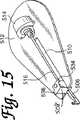
(項目3) 自動化分析器のステーション間で反応受容器を運搬するための運搬機構であって、該反応受容器は、操作構造体を含み、該運搬機構は、以下:
受容器キャリアアセンブリであって、回転軸の周りで回転可能であるように、そして該受容器キャリアアセンブリが該回転軸の周りで回転している間、反応受容器を受容して該反応受容器を運ぶように、構成され配置されている、受容器キャリアアセンブリ;
操作フック部材であって、該操作フック部材は、該受容器キャリアアセンブリと相互関係に置かれて、それに対して移動可能であるようにされており、該反応受容器の該操作構造体と噛み合い可能であるように、構成され配置されている、操作フック部材;および
フック部材駆動アセンブリであって、該フック部材駆動アセンブリは、フックモーターおよび親ネジ機構を含み、該フックモーターは、それに対して定位置で該受容器キャリアアセンブリに備えられた固定構造体を有し、そして該親ネジ機構は、該回転軸に対して略半径方向で配向されたネジ付きシャフトを含み、そして該操作フック部材に連結された末端を有し、ここで、該親ネジ機構は、該フックモーターに操作可能に連結されており、そして該フックモーターの動力運動を、該ネジ付きシャフトのいずれかの軸方向で、該フックモーターの該固定構造体に対して、該ネジ付きシャフトの運動へと変換するように、構成され配置されて、それにより、該操作フック部材により噛み合わされた反応受容器が該受容器キャリアアセンブリに対して移動できるように、該受容器キャリアアセンブリに対して、該操作フック部材の対応する運動を引き起こす、フック部材駆動アセンブリ、
を含む、機構。
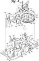
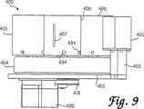
(項目4) 反応流体を含有する複数の反応受容器を受容し、該反応流体を温度制御環境で維持するためのインキュベータであって、該インキュベータは、以下:
ハウジングであって、該ハウジングは、その中に形成された受容器アクセス開口部を含み、該受容器アクセス開口部は、該受容器アクセス開口部を通って、該ハウジングの中または外へ該反応受容器を移動させるためにある、ハウジング;
コマンド応答性閉鎖機構であって、該コマンド応答性閉鎖機構は、該受容器アクセス開口部に近接した関係で、該ハウジングに接続されており、ここで、該コマンド応答性閉鎖機構は、該アクセス開口部を通しての該ハウジングへのアクセスを防止または許容するために、対応する閉鎖運動コマンドに応答して、該受容器アクセス開口部に対して、閉鎖位置と開放位置との間で移動可能であるように、構成され配置されており、
該ハウジングおよび該コマンド応答性閉鎖機構は、その中でインキュベーションチャンバを規定する囲壁を構成する、コマンド応答性閉鎖機構;
該インキュベーションチャンバと熱連絡している、熱源;
動力ファン機構であって、該動力ファン機構は、該インキュベーションチャンバ内に配置されており、そして該インキュベーションチャンバ内で空気運動を発生させて該インキュベーションチャンバの内部でのほぼ均一な温度分布を促進するように、構成され配置されている、動力ファン機構;
受容器キャリアであって、該受容器キャリアは、該インキュベーションチャンバ内に配置されており、そして複数の受容器ステーションを含み、該受容器ステーションの各々は、単一の反応受容器を運ぶように、構成され配置されており、該受容器キャリアは、該アクセス開口部に対して受容器運搬位置で、該複数の受容器ステーションのいずれかを提供するように、構成され配置されている、受容器キャリア、
を含む、インキュベータ。
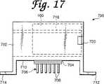
(項目5) 反応流体を含有する複数の反応受容器を受容し、該反応流体を温度制御環境で維持するためのインキュベータであって、該インキュベータは、以下:
ハウジングであって、該ハウジングは、その中に形成された受容器アクセス開口部を含み、該受容器アクセス開口部は、該受容器アクセス開口部を通って、該ハウジングの中または外へ該反応受容器を移動させるためにある、ハウジング;
コマンド応答性閉鎖機構であって、該コマンド応答性閉鎖機構は、該受容器アクセス開口部に近接した関係で、該ハウジングに接続されており、ここで、該コマンド応答性閉鎖機構は、該アクセス開口部を通しての該ハウジングへのアクセスを防止または許容するために、対応する閉鎖運動コマンドに応答して、該受容器アクセス開口部に対して、閉鎖位置と開放位置との間で移動可能であるように、構成され配置されており、
該ハウジングおよび該コマンド応答性閉鎖機構は、その中でインキュベーションチャンバを規定する囲壁を構成する、コマンド応答性閉鎖機構;
該インキュベーションチャンバと熱連絡している、熱源;
受容器キャリアであって、該受容器キャリアは、該インキュベーションチャンバ内で配置されており、そして複数の受容器ステーションを含み、該受容器ステーションの各々は、単一の反応受容器を運ぶように、構成され配置されており、該受容器キャリアは、該アクセス開口部に対して受容器運搬位置で、該複数の受容器ステーションのいずれかを提供するように、構成され配置されている、受容器キャリア;ならびに
受容器混合機構であって、該受容器混合機構は、該ハウジングに取り付けられており、そして該混合機構に対して操作可能な位置に配置された受容器ステーションで運ばれる反応受容器を攪拌して、それにより、該反応受容器に含有された該反応流体を混合するように、構成され配置されている、受容器混合機構、
を含む、インキュベータ。
(項目6) 自動化分析器のためのモジュールであって、該モジュールは、以下:
(A)該モジュールの1つから該モジュールの別のものへと反応受容器を運搬するための運搬機構であって、該反応受容器は、操作構造体を含み、該運搬機構が、以下:
(1)受容器キャリアアセンブリであって、該受容器キャリアアセンブリは、回転軸の周りで回転可能であるように、そして該受容器キャリアアセンブリが該回転軸の周りで回転している間、反応受容器を受容して該反応受容器を運ぶように、構成され配置されている、受容器キャリアアセンブリ;
(2)操作フック部材であって、該操作フック部材は、該受容器キャリアアセンブリと相互関係に置かれて、それに対して移動可能であるようにされており、該操作フック部材は、該反応受容器の該操作構造体と噛み合い可能であるように、構成され配置されている、操作フック部材;および
(3)フック部材駆動アセンブリであって、該フック部材駆動アセンブリは、フックモーターおよび親ネジ機構を含み、該フックモーターは、それに対して定位置で該受容器キャリアアセンブリに備えられた固定構造体を有し、そして該親ネジ機構は、該回転軸に対して略半径方向で配向されたネジ付きシャフトを含み、そして該操作フック部材に連結された末端を有し、ここで、該親ネジ機構は、該フックモーターに操作可能に連結されており、そして該フックモーターの動力運動を、該ネジ付きシャフトのいずれかの軸方向で、該フックモーターの該固定構造体に対して、該ネジ付きシャフトの運動へと変換するように、構成され配置されて、それにより、該操作フック部材により噛み合わされた反応受容器が該受容器キャリアアセンブリに対して移動できるように、該受容器キャリアアセンブリに対して、該操作フック部材の対応する運動を引き起こす、フック部材駆動アセンブリ、
を含む、運搬機構;ならびに
(B)反応流体を含有する複数の該反応受容器を受容し、該反応流体を温度制御環境で維持するためのインキュベータであって、該インキュベータは、以下:
(1)ハウジングであって、該ハウジングは、その中に形成された受容器アクセス開口部を含み、該受容器アクセス開口部は、該受容器アクセス開口部を通って、該ハウジングの中または外へ該反応受容器を移動させるためにある、ハウジング;
(2)コマンド応答性閉鎖機構であって、該コマンド応答性閉鎖機構は、該受容器アクセス開口部に近接した関係で、該ハウジングに接続されており、ここで、該コマンド応答性閉鎖機構は、該アクセス開口部を通しての該ハウジングへのアクセスを防止または許容するために、対応する閉鎖運動コマンドに応答して、該受容器アクセス開口部に対して、閉鎖位置と開放位置との間で移動可能であるように、構成され配置されている、コマンド応答性閉鎖機構、
ここで、該ハウジングおよび該コマンド応答性閉鎖機構は、その中でインキュベーションチャンバを規定する囲壁を構成する;
(3)該インキュベーションチャンバと熱連絡している、熱源;
(4)受容器キャリアであって、該受容器キャリアは、該インキュベーションチャンバ内に配置されており、そして複数の受容器ステーションを含み、該受容器ステーションの各々は、単一の反応受容器を運ぶように、構成され配置されており、該受容器キャリアは、該アクセス開口部に対して受容器運搬位置で、該複数の受容器ステーションのいずれかを提供するように、構成され配置されている、受容器キャリア、
を含む、インキュベータ、
を含み、
該インキュベータは、該インキュベータからの妨害なしで、該受容器キャリアアセンブリを回転させるように、該運搬機構の該受容器キャリアアセンブリにより揺り動かされる円弧の半径方向外側に配置され、そして該インキュベータは、該運搬機構の該受容器キャリアアセンブリにより揺り動かされる円弧に隣接して該アクセス開口部が配置されるよう配向され、それによって、該運搬機構が、以下:
(a)該コマンド応答性閉鎖機構が該開放位置にあるとき、該受容器キャリアアセンブリを該受容器アクセス開口部と協同して整列するように回転することにより、そして該操作フック部材を、該受容器キャリアアセンブリに対して第一方向で移動して、該反応受容器を、該受容器キャリアアセンブリから、該受容器アクセス開口部を通って、該複数の受容器ステーションの空の1個内で支持されて噛み合うように移動することにより、該運搬機構により運ばれる該反応受容器を、該アクセス開口部を通って、該空の受容器ステーションへと挿入すること、および
(b)該コマンド応答性閉鎖機構が該開放位置にあるとき、該受容器キャリアアセンブリを該受容器アクセス開口部と協同して整列するように回転することにより、そして該操作フック部材を、該第一方向で移動して、該操作フック部材の少なくとも一部を、該受容器アクセス開口部を通って挿入し、該受容器ステーションで運ばれる反応受容器の該操作構造体を噛み合わせることにより、引き続いて、該操作フック部材を、該反応受容器キャリアアセンブリに対して第二方向で移動して、該反応受容器を、該受容器ステーションから、該受容器アクセス開口部を通って、該受容器キャリアアセンブリ内で支持されて噛み合うように引き出すことにより、該受容器キャリアの該受容器ステーションから該反応受容器を取り除くこと、
を可能とする、モジュール。
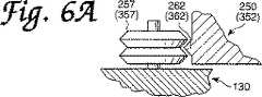
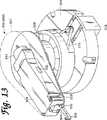
(項目7) 磁気応答性粒子を含みかつ反応受容器に含有される溶液に対して磁気分離精製操作を実行するための装置であって、該装置は、以下:
受容器キャリアユニットであって、磁気応答性粒子を含む溶液を含有する反応受容器を受容するように、そして該磁気分離精製操作を通じて該反応受容器を運ぶように、構成され配置されている、受容器キャリアユニット;
磁石移動構造体であって、磁場を発生させる少なくとも1個の磁石を含み、ここで、該磁石移動構造体は、該受容器キャリアユニットで運ばれる該反応受容器に対して、第一位置と第二位置との間で、該少なくとも1個の磁石を移動するように、構成され配置されている、磁石移動構造体、
ここで、該少なくとも1個の磁石が該第一位置にあるとき、該少なくとも1個の磁石の該磁場は、該磁気応答性粒子を、該少なくとも1個の磁石に隣接した該反応受容器の内面へと引き出し、そしてここで、該磁気応答性粒子に対する該磁場の効果は、該少なくとも1個の磁石が該第一位置にあるときよりも、該少なくとも1個の磁石が該第二位置にあるときの方が少ない;
流体運搬機構であって、該受容器キャリアユニットで運ばれる該反応受容器へと流体を選択的に分配するように、そして該反応受容器から流体を引き出すように、構成され配置されている、流体運搬機構;および
キャリア攪拌機構であって、該キャリア攪拌機構は、該受容器キャリアユニットに操作可能に連結されており、そして該受容器キャリアユニットに周期運動を与えて該受容器キャリアユニットで運ばれる該反応受容器に含有される該溶液を攪拌し混合するように、構成され配置されている、キャリア攪拌機構、
を含む、装置。
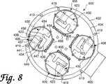
(項目8) アセンブリであって、以下:
第一リングアセンブリであって、該第一リングアセンブリは、第一回転軸の周りで回転可能であるように、構成され配置されており、該第一リングアセンブリは、内周および外周を有する環状流体コンテナキャリア部分を含み、該内周と該外周との間で、該流体コンテナキャリア部分が規定されており、該流体コンテナキャリア部分は、複数の流体コンテナを運ぶように、構成され配置されている、第一リングアセンブリ;および
第二リングアセンブリであって、該第二リングアセンブリは、該第一回転軸とほぼ平行な第二回転軸の周りで、該第一リングアセンブリとは無関係に回転可能であるように、構成され配置されており、該第二リングアセンブリは、該第二リングアセンブリの外周の少なくとも一部が該第一リングアセンブリの該流体コンテナキャリア部分の該内周に半径方向内側に配置されるように、該第一リングアセンブリに対して、位置づけられており、該第二リングアセンブリは、その上に複数のピペットチップを備えるように、構成され配置されている、第二リングアセンブリ;
を含む、アセンブリ。
(項目9) 前記第二リングアセンブリが、内周および外周を有するピペットチップキャリア部分を含み、該内周と該外周との間で、該ピペットチップキャリア部分が規定されており、ここで該アセンブリは、内部回転アセンブリをさらに含み、該内部回転アセンブリは、第一回転軸および第二回転軸に対して概して平行である第三回転軸の周りに第一リングアセンブリおよび第二リングアセンブリとは独立して回転可能であるように構成され配置されており、該内部回転アセンブリは、該第二リングアセンブリに対して配置されており、その結果、該内部回転アセンブリの外周の少なくとも一部が、該第二リングアセンブリの該ピペットチップキャリア部分の該内周に半径方向内向きに配置されており、該内部回転アセンブリがその上の複数の流体容器を運搬するために構成され配置されている、項目8に記載のアセンブリ。
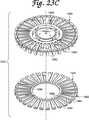
(項目10) 少なくとも1個のコンテナの流体内容物を攪拌するための装置であって、以下:
第一回転軸の周りで回転可能であるように構成され配置されている、ターンテーブル構造体;
1個またはそれ以上のコンテナホルダーであって、各々は、回転軸を有し、その中でコンテナを保持するように、構成され配置されており、該ターンテーブル構造体と共に回転可能であるように、また、各コンテナホルダーの該回転軸が該第一回転軸とほぼ平行になるように、該ターンテーブル構造体に取り付けられている、コンテナホルダー;
コンテナホルダー取付アセンブリであって、該コンテナホルダー取付アセンブリは、各1個のコンテナホルダーに付随しており、ここで、該コンテナホルダー取付アセンブリは、該付随コンテナホルダーを該ターンテーブル構造体に取り付けるように、そして該付随コンテナホルダーを、該第一回転軸および該コンテナホルダーの該回転軸の両方とほぼ平行であってそれらから間隔を置いて配置された第二回転軸の周りで、回転させるように、構成され配置されている、コンテナホルダー取付アセンブリ;および
回転運動連結要素であって、該回転運動連結要素は、該回転構造体および該コンテナホルダー取付構造体に操作可能に付随しており、そして該ターンテーブル構造体が該第一回転軸の周りで回転するにつれて、各コンテナホルダーを該第二回転軸の周りで回転させるように、構成され配置されている、回転運動連結要素、
を含む、装置。Reaction receptors can be moved between stations independently by a transport mechanism, and the stations can be operated in parallel to perform different assay procedures simultaneously on different reaction receptors, thereby allowing efficient analysis of the analyzer. Facilitates high throughput operations. Furthermore, the present invention can facilitate the placement of the various stations involved in nucleic acid based assays on a single, contained platform, thereby achieving efficient space utilization.
Other objects, features and characteristics of the present invention, including methods of operation and functions and interrelationships associated with structural elements, will be described in the following description and appended claims, with reference to the accompanying drawings. All of these figures form part of this disclosure, where like reference numerals indicate corresponding parts in the various figures.
In addition to the above, the present invention provides the following:
(Item 1) An automated process for isolating and amplifying a target analyte that may be present in a fluid sample contained in each of a plurality of reaction receptors, the process being performed at a plurality of stations, Between stations, each reaction receptor is transported by an automated receptor transport system that includes one or more automated receptor transport mechanisms, each automated receptor transport mechanism having at least one of the reaction receivers. Is recovered from one of the stations and transports the reaction receptor to another of the stations, the plurality of reaction receptors initially Held in a holding station for holding the plurality of reaction receptors prior to the start of the process, the process being carried out in each of the reaction receptors, the following:
Using the automated receiver delivery system to recover one of the reaction receivers from the holding station, wherein each of the reaction receivers recovered from the holding station receives a solid support material; Further comprising a step;
Using the automated receptor delivery system to deliver the reaction receptor to a first incubation station, the first incubation station including one or more incubators, each sealed Defining a temperature controlled incubation chamber;
Retaining the reaction receptor in the incubation chamber of the first incubation station for a period of time under conditions sufficient to immobilize the target analyte with the solid support material;
Using the automated receptor delivery system to recover the reaction receptor from the first incubation station;
Using the automated receptor delivery system to deliver the reaction receptor to a separation station;
Performing a target analyte separation procedure at the separation station, wherein the target analyte separation procedure isolates the solid support material in the reaction receiver from the fluid sample. And removing the fluid sample from the reaction receptor;
Recovering the reaction receiver containing the solid support material from the separation station using the automated receiver delivery system;
Using the automated receptor delivery system to deliver the reaction receptor to a second incubation station, the second incubation station comprising one or more incubators, each sealed Defining a temperature controlled incubation chamber, wherein the first and second incubation stations are independent of each other or share at least one incubator;
Dispensing amplification reagent to the reaction receptor before or after transporting the reaction receptor to the second incubation station; and under conditions sufficient to amplify the target analyte for a period of time And dwell the reaction receptor in the incubation chamber of the second incubation station,
Including the process.
(Item 2) The target analyte separation procedure further includes:
Dispensing a wash buffer to the reaction receiver after removing the fluid sample from the reaction receiver;
Stirring the reaction receiver to mix the wash buffer and the solid support material;
Isolating the solid support material in the reaction receiver from the wash buffer; and removing the wash buffer from the reaction receiver;
The method according to item 1, comprising:
(Item 3) A transport mechanism for transporting a reaction receptor between stations of an automated analyzer, the reaction receptor comprising an operating structure, the transport mechanism comprising:
A receiver carrier assembly for receiving a reaction receptor to be rotatable about the axis of rotation and while the receiver carrier assembly is rotating about the axis of rotation; A receiver carrier assembly configured and arranged to carry a carrier;
An operating hook member, wherein the operating hook member is interrelated with the receptor carrier assembly and adapted to move relative thereto, and engages with the operating structure of the reaction receiver An operating hook member configured and arranged to be possible; and a hook member drive assembly, the hook member drive assembly including a hook motor and a lead screw mechanism to which the hook motor is A locking structure provided on the receiver carrier assembly in a fixed position, and the lead screw mechanism includes a threaded shaft oriented generally radially with respect to the axis of rotation, and the operating hook member Wherein the lead screw mechanism is operably connected to the hook motor and provides power movement of the hook motor. Configured and arranged to translate into the movement of the threaded shaft relative to the fixed structure of the hook motor in any axial direction of the threaded shaft, thereby the operating hook A hook member drive assembly that causes a corresponding movement of the operating hook member relative to the receiver carrier assembly, such that a reaction receiver engaged by the member can move relative to the receiver carrier assembly;
Including the mechanism.
(Item 4) An incubator for receiving a plurality of reaction receptors containing a reaction fluid and maintaining the reaction fluid in a temperature controlled environment, the incubator comprising:
A housing, the housing including a receiver access opening formed therein, the receiver access opening passing through the receiver access opening and into or out of the housing. A housing for moving the receptacle;
A command responsive closure mechanism, wherein the command responsive closure mechanism is connected to the housing in proximity to the receiver access opening, wherein the command responsive closure mechanism is Movable between a closed position and an open position relative to the receiver access opening in response to a corresponding closing movement command to prevent or permit access to the housing through the opening Configured and arranged as
A command responsive closure mechanism, wherein the housing and the command responsive closure mechanism constitute an enclosure defining an incubation chamber therein;
A heat source in thermal communication with the incubation chamber;
A power fan mechanism, wherein the power fan mechanism is disposed within the incubation chamber and generates air motion within the incubation chamber to promote a substantially uniform temperature distribution within the incubation chamber. Power fan mechanism configured and arranged as such;
A receptor carrier, wherein the receptor carrier is disposed within the incubation chamber and includes a plurality of receptor stations, each of the receptor stations carrying a single reaction receptor. The receiver carrier is configured and arranged to provide any of the plurality of receiver stations in a receiver transport position relative to the access opening. Container carrier,
Including incubator.
(Item 5) An incubator for receiving a plurality of reaction receptors containing a reaction fluid and maintaining the reaction fluid in a temperature controlled environment, the incubator comprising:
A housing, the housing including a receiver access opening formed therein, the receiver access opening passing through the receiver access opening and into or out of the housing. A housing for moving the receptacle;
A command responsive closure mechanism, wherein the command responsive closure mechanism is connected to the housing in proximity to the receiver access opening, wherein the command responsive closure mechanism is Movable between a closed position and an open position relative to the receiver access opening in response to a corresponding closing movement command to prevent or permit access to the housing through the opening Configured and arranged as
A command responsive closure mechanism, wherein the housing and the command responsive closure mechanism constitute an enclosure defining an incubation chamber therein;
A heat source in thermal communication with the incubation chamber;
A receptor carrier, wherein the receptor carrier is disposed within the incubation chamber and includes a plurality of receptor stations, each of the receptor stations carrying a single reaction receptor. The receiver carrier is configured and arranged to provide any of the plurality of receiver stations in a receiver transport position relative to the access opening. A container carrier; and a receiver mixing mechanism that is attached to the housing and that is carried by a receiver station disposed at a position operable with respect to the mixing mechanism. A receiver mixing mechanism configured and arranged to agitate the vessel and thereby mix the reaction fluid contained in the reaction receiver;
Including incubator.
(Item 6) A module for an automated analyzer, the module comprising:
(A) A transport mechanism for transporting a reaction receptor from one of the modules to another of the modules, the reaction receptor including an operating structure, the transport mechanism comprising:
(1) a receptor carrier assembly, wherein the receptor carrier assembly is rotatable about a rotation axis and reacts while the receiver carrier assembly is rotated about the rotation axis; A receptor carrier assembly configured and arranged to receive the receptor and carry the reaction receptor;
(2) an operating hook member, wherein the operating hook member is positioned relative to the receiver carrier assembly so as to be movable relative to the receiver carrier assembly; An operating hook member configured and arranged to be engageable with the operating structure of the receiver; and (3) a hook member drive assembly comprising a hook motor and a lead screw The hook motor has a fixed structure provided to the receiver carrier assembly in a fixed position relative thereto, and the lead screw mechanism is oriented substantially radially with respect to the axis of rotation. Including a threaded shaft and having a distal end coupled to the operating hook member, wherein the lead screw mechanism is operably coupled to the hook motor, and And configured to translate the power movement of the hook motor into the movement of the threaded shaft relative to the fixed structure of the hook motor in any axial direction of the threaded shaft. Thereby causing a corresponding movement of the operating hook member relative to the receiver carrier assembly so that the reaction receiver engaged by the operating hook member can move relative to the receiver carrier assembly. Hook member drive assembly,
And (B) an incubator for receiving a plurality of the reaction receptors containing a reaction fluid and maintaining the reaction fluid in a temperature controlled environment, the incubator comprising:
(1) a housing, the housing including a receiver access opening formed therein, the receiver access opening passing through the receiver access opening and into or out of the housing; A housing for moving the reaction receptor to the housing;
(2) a command-responsive closure mechanism, wherein the command-responsive closure mechanism is connected to the housing in proximity to the receiver access opening, wherein the command-responsive closure mechanism is Move between a closed position and an open position relative to the receiver access opening in response to a corresponding closing motion command to prevent or permit access to the housing through the access opening A command-responsive closure mechanism, configured and arranged as possible
Wherein the housing and the command responsive closure mechanism constitute an enclosure defining an incubation chamber therein;
(3) a heat source in thermal communication with the incubation chamber;
(4) a receptor carrier, wherein the receptor carrier is disposed within the incubation chamber and includes a plurality of receptor stations, each of the receptor stations comprising a single reaction receptor; Configured and arranged to carry, wherein the receiver carrier is configured and arranged to provide any of the plurality of receiver stations in a receiver transport position relative to the access opening. The receptor carrier,
Including incubator,
Including
The incubator is disposed radially outward of an arc swung by the receiver carrier assembly of the transport mechanism to rotate the receiver carrier assembly without interference from the incubator, and the incubator is Oriented so that the access opening is positioned adjacent to an arc that is swung by the receiver carrier assembly of the transport mechanism, whereby the transport mechanism is:
(A) when the command-responsive closure mechanism is in the open position, by rotating the receiver carrier assembly in alignment with the receiver access opening, and Moving in a first direction relative to the receiver carrier assembly, the reaction receiver is moved from the receiver carrier assembly through the receiver access opening and into an empty one of the plurality of receiver stations. Inserting the reaction receptor carried by the transport mechanism through the access opening and into the empty receptor station by moving to be engaged and meshed with, and (b) the command By rotating the receiver carrier assembly in alignment with the receiver access opening when the responsive closure mechanism is in the open position and Moving the hook member in the first direction, inserting at least a portion of the operating hook member through the receiver access opening and carrying the operating structure of the reaction receiver carried in the receiver station Are subsequently moved in a second direction relative to the reaction receiver carrier assembly to move the reaction receiver from the receiver station to the receiver access opening. Removing the reaction receptor from the receptor station of the receptor carrier by pulling through the receptor carrier assembly to be supported and mated therethrough;
Enables the module.
(Item 7) An apparatus for performing a magnetic separation and purification operation on a solution containing magnetically responsive particles and contained in a reaction receptor, the apparatus comprising:
A receptor carrier unit configured and arranged to receive a reaction receptor containing a solution containing magnetically responsive particles and to carry the reaction receptor through the magnetic separation and purification operation; Receptor carrier unit;
A magnet moving structure comprising at least one magnet for generating a magnetic field, wherein the magnet moving structure is in a first position relative to the reaction receptor carried by the receptor carrier unit; A magnet moving structure configured and arranged to move the at least one magnet to and from a second position;
Here, when the at least one magnet is in the first position, the magnetic field of the at least one magnet causes the magnetically responsive particles to adjoin the at least one magnet of the reaction receptor. Pulled to the inner surface, and wherein the effect of the magnetic field on the magnetically responsive particles is such that the at least one magnet is in the second position than when the at least one magnet is in the first position. Less at some times;
A fluid carrying mechanism configured and arranged to selectively distribute fluid to and from the reaction receptor carried by the receptor carrier unit; A fluid agitation mechanism; and a carrier agitation mechanism, the carrier agitation mechanism being operably connected to the receiver carrier unit and providing periodic motion to the receiver carrier unit A carrier agitation mechanism configured and arranged to agitate and mix the solution contained in the reaction receiver being carried;
Including the device.
(Item 8) Assembly, the following:
A first ring assembly, wherein the first ring assembly is configured and arranged to be rotatable about a first rotational axis, the first ring assembly having an inner periphery and an outer periphery. A fluid container carrier portion is defined between the inner periphery and the outer periphery, the fluid container carrier portion being configured and arranged to carry a plurality of fluid containers. A first ring assembly; and a second ring assembly, wherein the second ring assembly rotates about a second rotational axis substantially parallel to the first rotational axis independent of the first ring assembly. Configured and arranged so that the second ring assembly is configured such that at least a portion of the outer periphery of the second ring assembly is the flow of the first ring assembly. Positioned relative to the first ring assembly to be radially inwardly disposed on the inner periphery of the body container carrier portion, the second ring assembly having a plurality of pipette tips thereon A second ring assembly constructed and arranged;
Including the assembly.
9. The second ring assembly includes a pipette tip carrier portion having an inner periphery and an outer periphery, wherein the pipette tip carrier portion is defined between the inner periphery and the outer periphery, wherein the assembly Further includes an internal rotation assembly that is independent of the first ring assembly and the second ring assembly about a third rotation axis that is generally parallel to the first rotation axis and the second rotation axis. The inner rotating assembly is positioned relative to the second ring assembly so that at least a portion of the outer periphery of the inner rotating assembly is Disposed radially inwardly on the inner periphery of the pipette tip carrier portion of a second ring assembly, wherein the inner rotating assembly includes a
(Item 10) An apparatus for agitating the fluid contents of at least one container, comprising:
A turntable structure configured and arranged to be rotatable about a first axis of rotation;
One or more container holders, each having a rotational axis, constructed and arranged to hold the container therein, and rotatable with the turntable structure A container holder attached to the turntable structure such that the rotation axis of each container holder is substantially parallel to the first rotation axis;
A container holder mounting assembly, wherein the container holder mounting assembly is associated with each one of the container holders, wherein the container holder mounting assembly is adapted to mount the associated container holder to the turntable structure. And rotating the associated container holder about a second rotational axis that is substantially parallel to and spaced from both the first rotational axis and the rotational axis of the container holder. A container holder mounting assembly configured and arranged; and a rotational motion coupling element operatively associated with the rotational structure and the container holder mounting structure; And each container holder as the turntable structure rotates about the first axis of rotation. A rotational motion coupling element configured and arranged to rotate the second rotational axis about the second rotational axis;
Including the device.
(好ましい実施形態の詳細な説明)
(分析器概要)
本発明に従った自動化診断分析器は、図1および2において一般に参照番号50により示される。分析器50は、好適には鋼で作製された内部フレーム構造62上に構築されたハウジング60を含む。分析器50は、好ましくは分析器を可動にさせるようにフレーム構造62に構造的に取りつけられたキャスタホイール64により支持される。Detailed Description of Preferred Embodiments
(Overview of analyzer)
An automated diagnostic analyzer according to the present invention is indicated generally by the
自動化アッセイを行うことに伴う多様なステーションおよびアッセイ標本は、ハウジング60内に収容される。加えて、多様な溶液、試薬およびその他のアッセイを行うのに使用される材料が、好ましくはハウジング60内に格納され、アッセイが分析器50を用いて行われるときに生成する廃物も同様である。 The various stations and assay specimens associated with performing automated assays are housed within the
ハウジング60は、図1に示される、試験受容器充填開口68を含み、これはハウジング60の前面に面するパネルに配置されるが、ハウジング60の他のパネルにも配置され得る。観察窓72を有するピペットドア70および観察窓76を有するカルーセルドア74が、ほぼ水平の作業表面66の上方に配置される。前面に突出するアーチ状パネル78は、以下に詳細を記載する標本カルーセルを収容する。はじき上げアーチ状標本ドア80がハウジングに旋回的に装着され、アーチ状パネル78に対して垂直に旋回するようにし、パネル78の後ろの標本カルーセルの前部へのアクセスを提供するようにする。ドアが閉められるときセンサが表示し、そして標本ドア80、カルーセルドア74およびピペットドア70が、分析操作中ロックされる。各ドアについてのロック機構は好ましくは、バネ戻りを有する(連続使用のための仕様の)DCロータリーソレノイドに装着されたフックを有する。好ましいロータリーソレノイドは、Lucas Control Systems,of Vandalia, Ohioから入手可能であり、型番L−2670−034とL−1094−34である。 The
拡張部102は、好ましくは透明または半透明材料から作成され、ハウジング60内で構成要素を動かすための垂直隙間を提供するようにする。 The
アッセイは、以下に述べる分析器50の多様なアッセイステーションの一般的な位置である、処理デッキ200上で主に行われる。例示の簡単のために、処理デッキ200は、その上にアッセイステーションが1つも取り付けられることなく図2に示される。処理デッキ200は、多様なステーションが直接にまたは間接に取り付けられるデータプレート82を備える。データプレート82は好ましくは機械加工されたアルミプレートから構成される。処理デッキ200は、また化学デッキとしてもまた公知であり、ハウジングの内部をデータプレート82の上方の化学領域または上部シャーシ、およびデータプレート82の下方に配置される格納領域または低部シャーシ1100に分離する。 The assay is performed primarily on the
多数のファンおよびルーバは好ましくはハウジング60の上部シャーシ部に提供され、上部シャーシ中へ空気循環を生成し、上部シャーシ内の過剰温度を回避する。 A number of fans and louvers are preferably provided in the upper chassis portion of the
本発明の分析器50はコンピュータ制御されるため、この分析器50はコンピュータコントローラを含み、図2のボックス1000として概略的に示され、「アッセイマネージャプログラム」として公知の高レベル分析器制御ソフトウェアを作動させる。アッセイマネージャプログラムは、化学デッキ200を通じて試験標本動作を監視しおよび制御するスケジューラルーチンを含む。 Since the
分析器50を制御するコンピュータシステム1000は、CPU、キーボード、モニタ、および必要に応じて含まれ得るプリンタ装置を含む単独型コンピュータシステムを含み得る。ポータブルカートもまた多様なコンピュータ構成要素を格納して支持するために提供され得る。あるいは、分析器制御ソフトウェアを作動させるためのコンピュータハードウェアは、分析器50のハウジング60内に一体的に収容され得る。 The computer system 1000 that controls the
分析器50の全体を通じて使用される電気モータおよびヒータの制御、およびバルク流体および廃棄流体コンテナ内の流体レベルのモニタリングなどの、低レベル分析器制御は、好ましくはMotorola 68332マイクロプロセッサを備える埋め込みコントローラにより行われる。分析器全体を通じて使用されるステッパモータもまた、E−M Technologies,Bala Cynwyd,Pennsylvaniaから入手可能な、予めプログラムされた既製のマイクロプロセッサチップにより好ましくは制御される。 Low level analyzer controls, such as control of electric motors and heaters used throughout the
処理デッキ200が図3および4に概略的に示される。図3は、処理デッキ200の一部の概略平面図を示し、そして図4は、処理デッキの概略斜視図を示す。データプレート82は、その上に全てのステーションが直接にまたは間接に装着される処理デッキ200の基礎を形成する。 A
処理デッキ200はハウジング60の前面の開口68から延びる、反応受容器入力列150を含む。複数の反応受容器が入力列150において積み重なる様式で充填される。入力列の目的は、処方された複数の反応受容器を保持し、そして順次に取り出し位置においてそれらを提供し、運搬機構により回収される(以下に述べる)。取り出し位置における反射センサにより、その位置における受容器の存在を確認する。入力列はまた、所与の時間においてその中に存在する受容器の数を数えるための装置も含む。 The
この列内の反応受容器シャトルアセンブリ(図示せず)は、受容器を、取り出し位置に向って受容器前進経路に沿って動かす。シャトルアセンブリがそのホーム位置および充分に伸張した位置にあるとき、光センサが表示する。この列は、その中に受容器を充填するために引き出し得る、引き出しを含む。しかし、引き出しが開けられる前には、ロックが解除され、そしてシャトルが受容器前進経路から外れなければならない。引き出しが再び閉められるとき、ロックされそしてシャトルは受容器と係合し、そしてそれらを取り出し位置に向って動かす。引き出しが閉められそしてシャトルが受容器と係合したとき、光センサが表示する。各受容器が運搬機構により取り出し位置から除去されるとき、受容器シャトルは、受容器を1受容器幅だけ移動させ、次の受容器が取り出し位置にくるようにする。 A reaction receptor shuttle assembly (not shown) in this row moves the receptors along the receptor advance path toward the removal position. The light sensor displays when the shuttle assembly is in its home position and fully extended position. This row includes a drawer that can be withdrawn to fill the receptacle therein. However, before the drawer can be opened, the lock must be released and the shuttle must be out of the receiver advance path. When the drawer is closed again, it is locked and the shuttle engages the receiver and moves them towards the removal position. A light sensor displays when the drawer is closed and the shuttle is engaged with the receiver. As each receptor is removed from the removal position by the transport mechanism, the receptor shuttle moves the receptor by one receptor width so that the next receptor is in the removal position.
反応受容器は、好ましくは試験管の直線状アレイを一体的に形成され、そして多試験管ユニットとしてまたはMTUとして公知である。この好ましい反応受容器(MTU)は、以下により詳細に記載される。 The reaction receptor is preferably integrally formed with a linear array of test tubes and is known as a multi-tube unit or MTU. This preferred reaction receptor (MTU) is described in more detail below.
第一リングアセンブリは、好ましい実施形態においては標本リング250を備え、データプレート82の上方の遠位にて旋回ジグプレート130上に取り付けられる。標本リング250はほぼ円状であり、好ましくはその環状流体コンテナキャリア部内で9つまでの標本トレイ300を保持する。そして各標本トレイは好ましくは20個の標本含有コンテナまたは試験管320を保持する。標本リング250は、第一の回転のほぼ垂直軸の周りに回転可能であるように構成および配置され、標本管320を、好ましくは自動化ロボットピペットシステムである、標本ピペットアセンブリ450に送達する。標本リング250の前面部はハウジング60に備わるはじき上げカルーセルドア80を通じてアクセス可能であり、試験管320のトレイ300が容易に標本リング250に充填され得、そして標本リングから容易に充填を取り出され得る。標本リング250は、モータにより駆動され、以下により詳細に記載される。 The first ring assembly includes a
第二リングアセンブリは、好ましい実施形態においてはピペットチップホイール350を備え、標本リング250の内側部に配置され、少なくともピペットチップホイール350の外側周辺の部分がリング250の内側周辺に半径方向内向きに配置されるようにする。ピペットチップホイール350は、その上に複数の市販のピペットチップのパッケージを備える。ピペットチップホイール350は、モータ駆動され、標本リング250の第一の回転軸にほぼ平行である、第二の回転軸の周りで、標本リング250と独立して回転させる。 The second ring assembly includes a
複数の流体コンテナを有するように構成および配置された内側回転可能アセンブリは、ピペットチップホイール350の内側部分に提供される。好適な実施形態においては、内側回転可能アセンブリは、ピペットチップホイール350(すなわち第二リングアセンブリ)および標本リング250(すなわち第一リングアセンブリ)内の半径方向内側に配置される、多軸ミキサ400を備える。多軸ミキサ400は、第一の回転軸および第二の回転軸にほぼ平行な第三の回転軸の周りに回転可能である、回転ターンテーブル414を含み、そしてその上に4つの独立して偏心的に回転するコンテナホルダ406が取りつけられる。コンテナホルダ406のそれぞれはコンテナを、好ましくは固定化したポリヌクレオチドおよびポリヌクレオチド捕捉プローブとともに磁性粒子のフルイドサスペンションを含む、プラスチックボトルの形態で受容する。各コンテナホルダ406は、形状がほぼ円筒状でありそして対称の軸または回転の軸を含む。多軸ミキサ400は、ホルダ406の中心に対して偏心的に各コンテナを回転させ、一方同時にターンテーブル414をその中心のまわりに回転させ、コンテナの実質的に一定な揺動を提供するようにし、流体中で磁性粒子を懸濁液に維持する。 An inner rotatable assembly configured and arranged to have a plurality of fluid containers is provided on the inner portion of
標本ピペットアセンブリ、またはロボット、450は、標本リング250およびピペットチップホイール350の上方の位置にあるフレーム構造62(図2参照)に取り付けられる。標本ピペットアセンブリ450は、ガントリーアセンブリに取りつけられた管状プローブ457を有するピペットユニット456を含み、X,Y,Z運動を提供する。特に、ピペットユニット456は、横レール454に形成されたトラック458に沿ってY方向に直線的に可動であり、そして横レール454は長手トラック452に沿ってX方向に長手に移動可能である。ピペットユニット456は、プローブ457の垂直のすなわちZ軸運動を提供する。標本ピペットアセンブリ450内の駆動メカニズムは、ピペットユニット456を分析器50内のピペット流体への正しいX,Y,Z座標へ配置させ、ピペットユニット456のプローブ457を洗浄し、ピペットユニット456のプローブ457の端部から保護チップを廃棄し、または不使用時の間(例えば「ホーム」ポジションにおいて)ピペットユニット456を収容する。標本ピペットアセンブリ450の各軸は、公知のそして通常の様式によってステッパモータにより駆動される。 A specimen pipette assembly, or robot, 450 is attached to a frame structure 62 (see FIG. 2) in a position above the
ピペットアセンブリは、好ましくは既製品である。現在好ましいのは、Cavro Inc.of Sunnyvale,Californiaから入手できるRobotic
Sample Processor、型番RSP9000である。このモデルは単一ガントリーアームを備える。The pipette assembly is preferably a ready-made product. Currently preferred is Cavro Inc. of Robotic available from Sunnyvale, California
Sample Processor, model number RSP9000. This model has a single gantry arm.
標本ピペットアセンブリ450は、好ましくはシリンジポンプ(図示されず)(the
Cavro XP 3000が使用された)およびDC駆動ダイアフラムシステム流体洗浄ポンプ(図示されず)に結合される。標本ピペットアセンブリ450のシリンジポンプは好ましくは、化学デッキ200の左手側の上方の置において、分析器50のハウジング60内の内部フレーム構造62に取りつけられ、そして好適なチュービング(図示されず)または他の導管構造によりピペットユニット456に接続される。The
Cavro XP 3000 was used) and a DC driven diaphragm system fluid wash pump (not shown). The syringe pump of the
標本調製開口252は、ジグプレート130内に提供され、標本ピペットアセンブリ450が、ジグプレート130の下方に配置される入力列150内の反応受容器160にアクセスし得るようにされる。 A
分析器50の標本ピペットアセンブリ450は、嵩上げカバープレート138の開口140、142を通じた標本リング250上に保持される標本管320に係合し、標本リング250およびピペットチップホイール350の後部の近くのピペットチップホイール350上に保持されるピペットチップに、それぞれ係合する。従って、操作者は、標本リング250および、ピペットチップホイール350の前部に、分析器の操作中にカルーセルドア開口80を通じて、ピペット手順を妨害することなくアクセスを有し得る。 The
チップ洗浄/処分ステーション340はジグプレート130上の標本リング250に隣接して配置される。ステーション340は、チップ処分チューブ342及び洗浄ステーションベイスン346を含む。標本調製の間、標本ピペットアセンブリ450のピペットユニット456は、洗浄ステーションベイスン346の上方の位置に動き得、この洗浄ステーションベイスン346において管状プローブ457が、プローブ457を通って蒸留水をポンピングすることにより、洗浄され得る。洗浄ステーションのベイスン346は好ましくは可撓性ホース(図示されず)により低部シャーシ1100中の液体廃棄コンテナに接続される。 The tip cleaning /
チップ処分チューブ342は直立管状部材を備える。標本管320からの反応受容器160への標本移動の間、細長ピペットチップは摩擦的にピペットユニット456の管状プローブ457の端部へ固定され、材料が標本管320から引かれ細長ピペットチップへ至るときまで、標本材料は、ピペットユニット456の管状プローブ457に接触しないようにされる。標本が標本管320から移された後、その標本を移すのに使用されたピペットチップが他の関係ない標本のために再び使用されないことが重要である。それゆえ、標本移動の後、ピペットユニット456をチップ処分チューブ342の上方に移動させ、そして使用された使い捨て可能ピペットチップを、チップ処分チューブ342の中に排出する。このチップ処分チューブ342は低部シャーシ1100に保有される固形廃物コンテナの1つに接続される。 The
細長ピペットチップは好ましくはまた、標的捕捉試薬を多軸ミキサ400に保持されるコンテナから、反応受容器160へ移動させるためのプローブ457に摩擦的に固定される。試薬移動に次いで、ピペットチップは廃棄される。 The elongated pipette tip is also preferably frictionally fixed to a
記載したように、標本リング250、ピペットチップホイール350、および多軸ミキサ400は、好ましくはデータプレート82の上方に支持されたヒンジ付きジグプレート130(図5および6を参照)に装着される。ジグプレート130は、その後端132においてヒンジが付けられ(図6参照)、プレートならびにそこに装着されたリング250、ホイール350およびミキサ400は、上方で旋回してジグプレートの下の化学デッキの領域へのアクセスを可能にする。 As described, the
第一の右側の運搬機構500は、入力列150とほぼ同じ平面上のジグプレート130および標本リング250の下のデータプレート82上に装着される。運搬機構500は、受容器キャリアアセンブリを規定する回転本体部504および、本体504内に装着され、そして動力フック部材駆動アセンブリにより、そこに対して伸張および後退する伸張操作フック506を備える。各反応受容器160は好ましくは、伸張操作フック506により係合され得る操作構造を含み、運搬機構500は反応受容器160に係合し得、反応受容器160を操作し得、そして、反応受容器160内でアッセイを行う間、反応受容器が1つのステーションから他のステーションへ順次に移動されるにつれ、反応受容器160を処理デッキ200上の1つの位置から他へ移動させる。 The first
第二の、または左側運搬機構502(第一分配アーム500と実質的に同じ構造)もまた処理デッキ200上に含まれる。 A second or left transport mechanism 502 (substantially the same structure as the first dispensing arm 500) is also included on the
複数の受容器定置ステーション210はまたジグプレート130の下方に配置される。定置ステーション210は、名前が意味するとおり、分析器50の処理デッキ200のアッセイ実施ステーションが反応受容器の受容を準備するまで、標本含有反応受容器を保持するための構造である。反応受容器は必要に応じて運搬機構500により、定置ステーション210から回収され、そして定置ステーション210へ挿入される。 A plurality of
右側軌道ミキサ550は、データプレート82に装着され、そして右側運搬機構500によりそこに挿入された反応受容器160を受容する。軌道ミキサが反応受容器160の内容物を混合するために提供される。混合が完結した後、右側運搬機構500は、反応受容器を右側軌道ミキサ550から除去し、そして処理デッキの他の位置に移動させる。 The
実質的に同一の構造の多数のインキュベータ600、602、604、606が提供される。インキュベータ600、602、604および606は好ましくは、ロータリーインキュベータである。実施されるべき特定のアッセイおよび所望のスループットが、必要なインキュベータの所望の数を決定するが、4つのインキュベータが分析器50に好ましくは提供される。 A number of
以下により詳細に記載するように、各インキュベータ(600、602、604、606)は、第一受容器アクセス開口を有し、そして第二受容器アクセス開口もまた有し得、そこを通して運搬機構500または502が反応受容器160をインキュベータへ挿入し得るか、またはインキュベータから反応受容器160を回収し得る。受容器がインキュベートされている間に、各インキュベータ(600、602、604、606)内には、個別の反応ステーション内に複数の反応受容器160を保持する回転受容器キャリアカルーセルがある。本発明の分析器50で好ましくは実施される、核酸に基づく診断アッセイのために、第一ロータリーインキュベータ600は標的捕捉およびアニーリングインキュベータであり、第二ロータリーインキュベータ602は、活性温度および事前読み込み冷却インキュベータ(「ATインキュベータ」としても公知である)であり、第三ロータリーインキュベータ604は増幅インキュベータであり、そして第四ロータリーインキュベータ606はハイブリダイゼーション保護アッセイインキュベータである。アッセイの全体の実施の中でのインキュベータの構造、機能、および役割は、以下により詳細に記載される。 As described in more detail below, each incubator (600, 602, 604, 606) has a first receiver access opening and may also have a second receiver access opening through which the
処理デッキ200はまた、好ましくは、複数の温度ランピング(temperature ramping)ステーション700を含む。このような2つのステーション700図3において示され、これらのステーションはインキュベータ602および604の間のデータプレート82に装着されている。追加のランピングステーションが処理デッキ200上で、運搬機構500,502のうちの1つによりアクセス可能な他の位置に配置され得る。 The
反応受容器160は、運搬機構500または502のいずれかにより、温度ランピングステーション700に配置され得、または温度ランピングステーション700から取り除かれ得る。各ランピングステーション700は、反応受容器およびその内容物の温度を、所望の温度まで上昇させるかまたは低下させるかのいずれかであり、その後受容器がインキュベータまたは他の温度感受性ステーション内に配置される。インキュベータ(600、602、604、606)のうちの1つに反応受容器を挿入する前に、反応受容器およびその内容を所望の温度に持っていくことにより、インキュベータ内の温度変動が最小化される。 The
処理デッキ200はまた磁気分離洗浄手順を実施するための、磁気分離洗浄ステーション800を含む。各磁気分離洗浄ステーション800は、一度に1つの反応受容器160で洗浄手順を収容しそして実施し得る。それゆえ、所望のスループットを達成するため、平行して作動する5つの磁気分離洗浄ステーション800が好ましい。受容器160は、左側運搬機構502により、磁気分離洗浄ステーション800に挿入されそして、磁気分離洗浄ステーション800から除去される。 The
試薬冷却ベイ900が、およそインキュベータ604および606の間のデータプレート82に装着される。試薬冷却ベイ900は、温度感受性試薬のボトルを保持するための複数のコンテナ受容器を有するカルーセル構造を備える。このカルーセルは、その中に形成されるピペットアクセス孔を備える蓋を有する冷却ハウジング構造内にある。 A
第二のまたは左側の軌道ミキサ552は、実質的に右側軌道ミキサ550に同一であり、インキュベータ606および604の間に配置される。左側軌道ミキサ552は、左側軌道ミキサ552内にある反応受容器内に流体を分配するための分配ノズル、およびラインを含む。 Second or left
試薬ピペットアセンブリ、またはロボット、470はフレーム構造62(図2参照)に装着された二重ガントリー構造を含み、そして処理デッキ200の左手側上のインキュベータ604および606のほぼ上方に配置される。特に、試薬ピペットアセンブリ470はピペットユニット480および482を含む。ピペットユニット480は、管状プローブ481を含み、そして横レール476のトラック474に沿って、ほぼX方向に、直線移動のために装着され、そしてピペットユニット482もまた、管状プローブ483を含み、横レール478のトラック484に沿って、ほぼX方向に、直線移動のために装着される。横レール476および478は、長手トラック472に沿って、ほぼY方向に並進し得る。各ピペットユニット480、482は、それぞれプローブ481、483の独立の垂直な、またはZ軸運動を提供する。アセンブリ470内の駆動機構は、ピペットユニット480、482を、分析器50内でピペット流体に対して正確なX,Y,Z座標に配置させ、各ピペットユニット480、482の管状プローブ481、483を洗浄するか、または不使用(例えば「ホーム」位置にある)の期間の間のピペットユニット480、482を収容する。ピペットアセンブリ470の各軸は、ステッパモータにより駆動される。 The reagent pipette assembly, or robot, 470 includes a dual gantry structure mounted to a frame structure 62 (see FIG. 2) and is positioned substantially above the
この試薬ピペットアセンブリ470は、好ましくは既製品である。現在好ましいユニットは、2つのガントリーアームを備えた、Cavro Robotic Sample Processor、モデルRSP9000である。 This
試薬ピペットアセンブリ470のピペットユニット480、482はそれぞれ好ましくは、各シリンジポンプ(図示されず)(Cavro XP 3000 が使用された)およびDC駆動ダイアフラムシステム流体洗浄ポンプに結合される。試薬ピペットアセンブリ470のシリンジポンプは、好ましくは化学デッキ200の左手側の上方の位置において分析器50のハウジング60内の内部フレーム構造62に装着され、そして好適な配管(図示されず)または他の導管構造により、各ピペットユニット480、482に接続される。 The
各ピペットユニット480、482は好ましくは、容量性レベル感知能力を含む。容量性レベル感知は、医療器具分野において一般に公知であり、キャパシタの誘電性がキャパシタの1つのプレートとしてのピペットユニット、および対向するプレートとしてのピペットユニットにより係合されたコンテナの周囲の構造およびハードウェア、により形成された場合のキャパシタンスの変化ならびに、ピペットユニットのプローブがコンテナ内の流体を貫入した場合に感知する空気から流体への変化を利用する。ピペットユニットの垂直方向の動きを駆動するステッパモータをモニタすることにより知られ得る、ピペットユニットのプローブの垂直位置を確認することにより、ピペットユニットにより係合されるコンテナ内の流体のレベルが決定され得る。 Each
ピペットユニット480は、試薬を、試薬冷却ベイ900から、インキュベータ606または軌道ミキサ552内に配置される反応受容器へ、移動させ、そしてピペットユニット482は試薬物質を、試薬冷却ベイ900から、増幅インキュベータ604または軌道ミキサ552内に配置される反応受容器に、移動させる。
ピペットユニット480、482は、容量性レベル感知を使用し、コンテナ内の流体レベルを確認し、そしてピペットユニットのプローブの端部のほんの小部分を、コンテナからのピペット流体へ浸す。ピペットユニット480、482は好ましくは、それぞれ管状プローブ481、483内に流体がピペットされるとき下降し、プローブの端部を一定の深さまで浸して維持する。ピペットユニット480または482の管状プローブの中に試薬を引き込んだ後、ピペットユニットは、各プローブ481または483の端部に10μlの最小移動空気ギャップを形成し、ピペットユニットが化学デッキ200の上方の他の位置へ動かされるとき、プローブの端部からの滴りが無いことを確実にする。
本発明の分析器50において実施されるアッセイの結果は、好ましくは、好適な調製工程の終了における容器162から発せられる、化学ルミネッセンスまたは光の量により確認される。特に、アッセイの結果は、アッセイの終了におけるハイブリダイズされたポリヌクレオチドプローブに関連する標識により発せられる光の量から、決定される。従って、処理デッキ200は、照度計950を含み、反応受容器の内容により発せられる光の量の検出および/または定量化をする。要するに、照度計950は、ハウジングを備え、そのハウジングを通って反応受容器が、運搬機構、光電子増倍管、および関連する電子品の影響のもとで、移動する。多様な照度計の実施形態が以下により詳細に記載される。 The results of the assay performed in the
処理デッキ200はまた、好ましくは不活化列750を含む。分析器50の中で実施されるアッセイは、少なくとも1つの対象の生物または細胞に属する核酸の単離および増幅を含む。従って、反応受容器160の内容物を不活化させることが望ましく、典型的には、漂白剤ベースの試薬を、アッセイの終了において反応受容器160に分配することにより、不活化させる。この不活化は、不活化列750内において生じる。 The
不活化に次いで、反応受容器160の不活化された内容物は低部シャーシ1100の液体廃物コンテナの1つに格納され、そして使用された反応受容器は、低部シャーシ1100内の専用固形廃棄物コンテナに廃棄される。この反応受容器は好ましくは再使用されない。 Following inactivation, the inactivated contents of the
(分析器操作)
上記に記載の、分析器50の操作、ならびにステーション、構成要素、およびモジュールの構成、協同作用、および相互作用は、分析器50を用いて実施され得る1つのタイプのアッセイの実施における単一の試験標本について、分析器50の操作を記載することにより、説明される。本明細書中に記載される1つ以上のステーション、構成要素、およびモジュールの使用を要求する他の診断アッセイもまた、分析器50を用いて実施され得る。本明細書中の特定のアッセイ手順の記載は、単に、分析器50の多様なステーション、構成要素、およびモジュールの、操作および相互作用を例示する目的のためであり、限定の意図はない。診断試験の当業者は、多様な化学的および生物的アッセイが、本発明の分析器50を使用して自動化された様式で、実施され得ることを理解する。(Analyzer operation)
The operation of the
分析器50は初期的には、バルク流体を、低部シャーシ1100のバルク流体格納ベイに充填すること、およびバルク流体コンテナを適切なホース(図示されず)に接続することにより、アッセイの実行のために構成される。 The
分析器は、好ましくは順次プロセスにおいて起動(powered up)され、最初にプロセスの初期において必要とされるステーション、またはモジュールに電源投を入れ、そして次いでプロセスの後の方まで必要とされないステーションに、電源を入れる。これはエネルギーを節約し、そしてまた全分析器の起動に伴う大きな電源サージ(そしてこれはサーキットブレーカをトリップさせ得る)を回避するのに役立つ。この分析器はまた不使用期間中の「スリープ」モードを採用する。スリープモードの間、最小量の電力が分析器に供給され、さらに、完全なシャットダウンからの分析器の起動に必要な大きなサージを避ける。 The analyzer is preferably powered up in a sequential process, initially powering the station or module needed early in the process, and then to a station not needed until later in the process, Turn on the power. This saves energy and also helps avoid large power surges (and this can trip the circuit breaker) associated with starting up the entire analyzer. The analyzer also employs a “sleep” mode during periods of non-use. During sleep mode, a minimum amount of power is supplied to the analyzer, further avoiding the large surge required to start the analyzer from a complete shutdown.
多数の反応受容器160は、好ましくはプラスチックの形態であり、多試験管ユニット(MTU)を一体的に形成し、このことは以下により詳細に述べるが、開口68を通じて、入力列150に充填される。これ以後は、反応受容器160は、MTUとし、分析器50を使用する好ましい様式と一致する。 The
入力列150内の反応受容器シャトルアセンブリ(図示されず)は、MTU160を充填開口68から列150の端部における取りだし位置へ、移動させる。右側運搬機構500はMTU160を、列150の端から取り、そしてMTUをバーコードリーダ253へ動かし、そのMTUを確認するMTU上の独自のバーコードラベルを読む。バーコードリーダ253から、MTUを、開口252の下方の利用可能な標本移動ステーション255へ移動させる。 A reaction receptor shuttle assembly (not shown) in the
(多試験管ユニット)
図58に示されるように、MTU160は、複数の、好ましくは5個の個別の容器162を備える。容器162は、好ましくは開放頂部端と閉鎖底部端を備える円筒形管の形態であり、互いに接続リブ構造164により接続される。この接続リブ構造164は、MTU160のいずれかの側に沿った長手に延びる下向きに面するショルダを規定する。(Multiple test tube unit)
As shown in FIG. 58, the
このMTU160は、好ましくは射出成型ポリプロピレンから形成される。最も好ましいポリプロピレンはWilmington,DelawareのMontell Polyolefinsにより販売され、商品番号PD701NWである。Montell材料が使用されるのは、成型しやすく、分析器50の操作の好適なモードで化学的に融和性があり、そして化学ルミネッセンスの正確な検出または定量を妨害し得る静電放電現象の数が限られるからである。 The
アーチ状シールド構造169は、MTU160の一端に提供される。運搬機構500、502の1つにより係合されるMTU操作構造166は、このシールド構造169から延びる。MTU操作構造166は、プレート168の対向端上に垂直に伸びる片167とともにシールド構造169から延びる、横伸張プレート168を備える。ガセット壁165は、シールド構造169と垂直片167との間で横プレート168から下向きに延びる。 An
図60に示されるように、シールド構造169および垂直片167は、互いに面する凸面を有する。MTU160は、運搬機構500、502およびその他の構成要素により、以下に記載されるように、係合部材を横方向に(「A」方向に)、シールド構造169と垂直片167との間の空間へ移動させることにより、係合される。シールド構造169と垂直片167の凸面は、空間へ横方向運動を経る係合部材のためのより広いエントリーのポイントを提供する。垂直片167とシールド構造169の凸面は、それぞれ隆起部分171、172を含み、その中央部分で形成される。部分171、172の目的は以下に述べる。 As shown in FIG. 60, the
平坦ラベル受容面175を有する、ラベル受容構造174は、シールド構造169およびMTU操作構造166の反対のMTU160の端部上に提供される。スキャン可能バーコードなどのラベルは、表面175上に配置され得、MTU160上の確認および指示情報を提供する。 A
MTU160は好ましくは、各それぞれの容器162の開口に隣接して、チップレット(tiplet)保持構造176を含む。各チップレット保持構造176は、接触制限チップレット170を受容する円筒状オリフィスを提供する。チップレット170の構造および機能は、以下に記載される。各保持構造176は、チップレット170を、MTU160が逆にされたときチップレット170が保持構造176から外れることを防ぐような様式で、摩擦的に受容するように構成され配置される。しかしチップレット170は、ピペットにより係合するされるとき保持構造176から除去されることを可能にする。 The
図59に示されるように、チップレット170は、周囲リムフランジ177およびチップレット170の下部179よりほぼ大きい直径の上部カラー178を有するほぼ円筒構造を備える。チップレット170は、好ましくは導電性ポリプロピレンから形成される。チップレット170が保持構造176のオリフィスに挿入されると、フランジ177は構造176の頂部に接触し、そしてカラー178はチップレット170と保持構造176との間でぴったりとした、しかし開放可能な締まり嵌めを提供する。 As shown in FIG. 59, the
軸方向に伸張する貫通孔180はチップレットを通る。孔180はチップレット170の頂部において外側に広がった端部181を含み、ピペット管状プローブ(図示されず)のチップレット170への挿入を容易にする。2つの環状のリッジ183を孔180の内壁に並べる。リッジ183は、チップレット170とチップレット170へ挿入される管状プローブとの間の締まり摩擦嵌めを提供する。 A through
チップレット170の低部端は好ましくは、傾斜部182を含む。チップレット170がMTU160の容器162などの反応受容器の底部に挿入される吸引器の端部で使用されるとき、傾斜部182は、真空がチップレット170の端部と反応容器の底部との間で形成されるのを防ぐ。 The lower end of
(低部シャーシ)
本発明の低部シャーシの実施形態は、図52から54に示される。低部シャーシ1110はブラックポリウレタンパウダーコートを有する鋼フレーム1101、シャーシの下方に配置された引き出しドリップトレイ1102、右側引出し1104、および左側引出し1106を含む。左側引出し1106は実際には低部シャーシ1100内の中央に配置される。低部シャーシ1100のさらに左側には多様な電力供給システム構成装置および他の分析器装置(例えば取りつけプラットフォーム1154に装着された7つのシリンジポンプ1152、振動分離器(示されず)上の低部シャーシ1100のフロアに好ましくは装着された真空ポンプ1162、電力供給ユニット1156、電源フィルタ1158およびファン1160など)を収容する。(Lower chassis)
An embodiment of the lower chassis of the present invention is shown in FIGS. The
異なるシリンジポンプ1152が各5つの磁気分離洗浄ステーション800のために指定され、1つは左側軌道ミキサ552のために指定され、そして1つは不活化列750のために指定される。シリンジポンプが好ましいが、蠕動ポンプが代替として使用され得る。 Different syringe pumps 1152 are designated for each of the five magnetic separation and cleaning
真空ポンプ1162は各磁気分離洗浄ステーション800および不活化列750に作用する。好ましい真空ポンプの定格は、0”Hgで5.3〜6.5cfmおよび5”Hgで4.2〜5.2cfmである。好ましい真空ポンプは、Sheboygan,WisconsinのThomas Industries,Inc.から型番2750CGHI60として入手可能である。キャパシタ1172はポンプ1162に付随して販売される。 A vacuum pump 1162 acts on each magnetic
電力供給ユニット1156は好ましくは、ASTEC型番VSI−B5−B7−03であり、Carlsbad,CaliforniaのASTEC America,Inc.から入手可能である。電力供給ユニット1156は50〜60Hzの範囲の220ボルト、すなわち典型的な220ボルト壁コンセントからの電力を受ける。電源フィルタ1158は、好ましくはCorcomモデル20MVIフィルタであり、Libertyville,IllinoisのCorcom,Inc.から入手可能である。ファン1160は好ましくは、San Ysidro CaliforniaのComair Rotronから入手可能である、Whisper XLDCファンである。各ファンは24VDCモータで駆動されそして75cfm出力を有する。図52に示されるように、ファン1160は好ましくは低部シャーシ1100の左側外壁に近接して配置される。ファン1160は好ましくは外側に方向付けられ、その右側からその左側へ低部シャーシから空気が引かれ、そして低部シャーシから過剰な熱を引く。 The power supply unit 1156 is preferably ASTEC model number VSI-B5-B7-03 and is available from ASTEC America, Inc. of Carlsbad, California. Is available from The power supply unit 1156 receives power from 220 volts in the range of 50-60 Hz, ie from a typical 220 volt wall outlet. The
他の電源供給システム構成要素は低部シャーシ1100の背面左手側に収容され、電源スイッチ1174および電源入力モジュール1176を含む。電源スイッチ1174は、好ましくは、Cleveland, OhioのCutler−Hammer Division of Eaton Corporation から入手可能である、Eatonサーキットブレーカスイッチ2極シリーズJA/Sである。電源入力モジュール1176は、外部電源に分析器50が接続されるための電源コード(図示されず)が接続される。分析器50の電源供給システムはまた、そこに複数の電気ターミナルを装着するためのターミナルブロック(図示されず)、半導体スイッチ(図示されず)、およびRS232
9ピンコネクタポートを含む。この半導体スイッチは、好ましくはCal Switch,Carson City,Californiaから入手可能である、Crydom
Series1、型番D2425であり、異なる回路の間でスイッチングするためにある。そしてRS232 9ピンコネクタポートは、分析器50を外部コンピュータコントローラ1000へ接続するためにある。Other power supply system components are housed on the back left hand side of the
Includes 9-pin connector port. This semiconductor switch is preferably Crydom, available from Cal Switch, Carson City, California
Series 1, model number D2425, for switching between different circuits. The RS232 9-pin connector port is for connecting the
右側引出しおよび左側引出しベイは好ましくは、分析器の前の1つまたは2つのドア(図示されず)の後ろで閉じられ、これ/これらは好ましくは、分析器の操作の間、アッセイマネージャプログラムによりロックされる。マイクロスイッチが、好ましくはドア閉状態を確認するために提供される。さらに左のベイは、正面パネルによりカバーされる。端部パネルはシャーシを包囲するために低部シャーシの対向端上に提供される。 The right and left drawer bays are preferably closed behind one or two doors (not shown) in front of the analyzer, which are preferably by the assay manager program during analyzer operation. Locked. A microswitch is preferably provided to confirm the door closed condition. Furthermore, the left bay is covered by a front panel. End panels are provided on opposite ends of the lower chassis to enclose the chassis.
4つのレバー脚1180は、シャーシ1100の4つのコーナから下に延びる。レバー脚1180は、その低部端にてパッドを有するネジ切りシャフトを含む。分析器が所望の位置にあるとき、脚1180は、パッドが床に係合して分析器を水平出しして安定化させるまで、低められ得る。脚はまた、分析器がそのキャスタで移動されることを可能にするために上昇され得る。 Four
典型的に低部シャーシ1100のコンテナに含まれるバルク流体は、(固定化された標的を洗浄するための)洗浄緩衝液、(固定ピペットチップを洗浄するための)蒸留水、診断試験試薬、(試験試薬および標本の上に重ねるための浮遊流体として使用する)シリコンオイル、および(サンプル不活化のために使用される)漂白剤ベース試薬を含み得る。 The bulk fluid typically contained in the container of the
右側引出し1104は、図53に詳細に示され、右側引出し1104は、正面引出しハンドル1105を有する箱状引出し構造を含む。引き出しハンドル1105は、通常の引き型引出しハンドルとして示され、分析器50の好適な実施形態においては、ハンドル1105は、Tハンドルラッチであり、これらはSouthco,Inc.of Concordville,Pennsylvaniaから入手可能である。引き出し1104はスライドブラケット(図示されず)上の低部シャーシに取り付けられ、引き出し1104は低部シャーシへ引き入れられ得、および低部シャーシから引き出され得るようにする。センサ(図示されず)が好ましくは引き出し1104が閉じられたことを確認するために提供される。引き出しの正面部は、ボトル1128(図52に示される)およびボトル1130(また図52に示される)を保持するためのボトル受容器1122を含む。ボトル1128は、専用のピペット洗浄廃物含有ボトルであり、ボトル1130は、磁気洗浄、標的捕捉手順からの含有廃物のための専用廃物ボトルである。ボトル1130は好ましくは排出(evacuated)される。 The
低部シャーシ1100において要求されるいずれかのボトルがないとき、分析器50は処理アッセイを始めない。ボトル受容器1122は、好ましくはボトル存在センサ(図示されず)を含み、各受容器1122内のボトルの存在を確認する。ボトル存在センサは好ましくは、West Des Moines,IowaのSUNX/Ramco Electric,Inc.から入手可能である、拡散反射型光センサ、モデルEX−14Aである。 When there is no bottle required in the
右側引出し1104はさらにその中に、使用されたMTUおよび標本チップを保持するための廃物箱(bin)1108を含む。廃物箱1108は、その頂部にセンサを取りつけるためのセンサマウント1112を有する開放ボックス構造である。このセンサは好適には、廃物箱1108が満ちているかどうかを検出するための、24VDC光拡散反射スイッチ(図示されず)である。もう1つの拡散反射型光センサ(図示されず)が、右側引出し1104内に位置し、廃物箱1108が適所にあることを確認する。再び、拡散反射型光センサは、West Des Moines,IowaのSUNX/Ramco Electric,Inc.から入手可能である、モデルEX−14Aが好適である。 The
デフレクタ1110は、廃物箱1108の側部から斜めに延びる。デフレクタ1110は、シュートの直接下に配置され、シュートを通って使用されたMTUが廃物箱1108に落とされ、そして落とされたMTUを廃物箱1108の真中に向け、廃物箱1108のコーナにおけるMTUの山積みを回避する。デフレクタ1110は、好ましくは旋回的に取りつけられ、実質的に垂直な位置まで上方に旋回し得、そのため廃物箱1108と整列しそしてデフレクタ1110を覆う廃物袋が廃物箱1108から除去されるとき、デフレクタ1110は、袋が引き出されるときともに上向きに旋回し、そして従って袋を破らないようにさせる。 The
プリント回路基板(図示されず)およびカバー1114は廃物箱1108の正面に装着され得る。センサマウント1116および1117もまた廃物箱1108の正面に装着される。センサ1118および1119はセンサマウント1116に装着され、そしてセンサ1120および1121はセンサマウント1117上に装着される。センサ1118、1119、1120および1121は好ましくはDC容量性近接センサである。上方センサ1118、1119は、ボトル1128および1130が満ちたとき表示し、そして底部センサ1120,1121は、ボトルが空のとき表示する。センサ1118〜1121は好ましくはReno,NevadaのStedham Electronics Corporationの型番C2D45AN1−Pから入手可能である。これらのセンサは、低部シャーシ1100の緊密な領域内で少ない空間しか必要としない、その比較的フラットな物理的プロフィールのため、およびStedhamセンサが3〜20mmの範囲の所望の感知距離を提供するので選択された。 A printed circuit board (not shown) and
アッセイマネージャプログラムが、右側引出し1104内の廃物流体コンテナのいずれかが初期に空でないことを検出すれば、分析器50は好ましくはいずれのアッセイも実行しない。 If the assay manager program detects that any of the waste fluid containers in the
容量性近接センサ1118〜1121およびボトル存在、廃物箱存在、および右側引出し1104の廃物箱満杯光センサは、カバー1114の後ろのプリント回路基板(図示されず)上に接続され、そしてこのプリント回路基板は分析器50の埋め込みコントローラに接続される。 Capacitive proximity sensors 1118-1121 and the bottle presence, waste bin presence, and
右側引出し1104が低部シャーシ1100から完全には引くことができないため、廃物袋ライナーを設置しおよび除去するために廃物箱にアクセスすることを可能とするために、廃物箱1108を前方に引くことを可能にすることが必要である。この目的のため、ハンドル1126が廃物箱1108の正面に取り付けられ、そしてテフロン(登録商標)ストリップ1124が、右側引出し1104の底部フロアに配置され、ボトル1128および1130が除去されるとき、引き出し1104内の廃物箱1108の前方および後方への滑りを容易にする。 Pull the
左側引出し1106の詳細は図54に示される。左側引出し1106は、正面取付けハンドル1107を有する箱状構造を含み、低部シャーシ1100内でスライドブラケット(図示されず)上に取りつけられる。ハンドル1107は、通常の引き型引出しハンドルとして示されるが、分析器50の好ましい実施形態では、ハンドル1107はTハンドルラッチであり、Concordville,PennsylvaniaのSouthco,Inc.から入手できるものなどである。センサが、左側引出し1106が閉められていることを確認するために提供される。 Details of the
左側引出し1106は、その上にチップレット廃物箱満杯センサ(図示されず)を装着するための取りつけ構造1135を備える、チップレット廃物箱1134を含む。チップレット廃物箱存在センサは好ましくは、左側引出し1106に提供され、チップレット廃物箱1134が正しく設置されることを確認する。拡散反射型光センサはWest Des Moines,IowaのSUNX/Ramco Electric,Inc.,から入手でき、モデルEX−14Aがチップレット廃物箱満杯センサおよびチップレット廃物箱存在センサの両方に好適である。 The
束ね構造1132が低部シャーシ1100内の多様な配管および/またはワイヤ(図示されず)を固定するために、および束ねるために提供される。使用される好ましい束ね構造は、East Providence,Rhode IslandのIgus,Inc.により製造され販売されるEnergy Chain Systemsである。 A
プリント回路基板1182は、チップレット廃物箱1134の後ろに配置されるパネル1184の後ろに装着される。ソレノイドバルブ取りつけパネル1186は、チップレット廃物箱1134の下方に配置される。 The printed
左側引出し1106は、その中に6つの類似のサイズのボトルを保持するための前方コンテナ保持構造を含む。コンテナ構造は、分割壁1153、1155、1157および1159および湾曲ボトル適合正面エッジを有するコンテナブロック1151を含み、これらが合わせて6つのコンテナ保持領域を規定する。低部センサ1148および上部センサ1150(各6つ)が分割壁1155、1157および1159に装着される。上部センサ1148および下部センサ1150は好ましくは、DC容量性近接センサ(好ましくは,そのフラットなプロフィールと感知範囲のために選ばれた、Reno,NevadaのStedham Electronics Corporationから入手可能であるセンサ、型番C2D45AN1−P)である。上部センサ1150は、コンテナ構造に保持されるボトルが満杯になるときに表示し、そして低部センサ1148は、ボトルが空のとき表示する。好ましい装置においては、左2つのボトル1146は検出剤(「Detect I」)、真中の2つのボトル1168は、シリコンオイル、そして右の2つのボトル1170は、他の検出剤(「Detect II」)を含む。 The
ボトル存在センサ(図示されず)は、コンテナブロック1151および分割壁1153、1155、1157、および1159により規定されるコンテナ保持領域のそれぞれにおいて好ましくは提供され、各コンテナ保持領域におけるボトルの存在を確認する。ボトル存在センサは好ましくは、West Des Moines,IowaのSUNX/Ramco Electric,Inc.,から入手できる、モデルEX−14Aである、拡散反射型光センサである。 A bottle presence sensor (not shown) is preferably provided in each of the container holding areas defined by the
中央に配置された大型のコンテナ受容器1164は、好ましくは脱イオン水を含有するボトル1140(図52に示される)を保持する。コンテナ受容器1166(図54において1つのみが見られる)は、好ましくは洗浄緩衝溶液を含有するボトル1142および1144(図52においても示される)を保有する。受容器1164および1166の間の分割壁1143はその上に、ボトル1140、1142および1144の中の流体レベルをモニタするための、センサ1141などのセンサを取りつける。センサ1141などのセンサは、好ましくはDC容量性近接センサ(好ましくはReno,NevadaのStedham Electronics Corporationから入手可能の型番C2D45AN1−Pのセンサ)である。 A centrally located
コンテナ受容器1164および1166は好ましくは、ボトルが正しくそれらのそれぞれの受容器に配置されることを確認する、ボトル存在センサ(図示されず)を含む。このボトル存在センサは好ましくは拡散反射型光センサであり、West Des Moines,IowaのSUNX/Ramco Electric,Inc.,から入手できる、モデルEX−14Aである。
アッセイマネージャプログラムが、左側引出し1106におけるバルク流体受容器のいずれかが初期的に空であると決定すると、分析器50はいずれのアッセイの実行も開始しない。 If the assay manager program determines that any of the bulk fluid receptors in the
容量性近接流体レベルセンサ、多様なボトル存在センサ、チップレット廃物箱満杯センサおよびチップレット廃物存在センサは全て、プリント回路基板1182に接続され、そしてプリント回路基板1182は、分析器50の埋め込まれたコントローラに接続される。 The capacitive proximity fluid level sensor, the various bottle presence sensors, the tiplet waste box full sensor and the tiplet waste presence sensor are all connected to the printed
4つのソレノイドバルブ(図示されず)が、ソレノイドバルブ取りつけパネル1186の下方に装着される。ソレノイドバルブはバルク流体ボトルを接続し、ここで流体は対のボトルに貯蔵され、すなわち、ボトル1140,1142は洗浄緩衝溶液を含み、2つのボトル1146は「Detect I」試薬を含み、2つのボトル1168はオイルを含み、そして2つのボトル1170は「Detect II」試薬を含む。ソレノイドバルブは、各容量性近接センサからの信号に応答して、同じ流体を含む2つのボトルの1つが空のとき、流体が引かれるボトルを切り替える。加えて、ソレノイドバルブは所定の数の試験が実施された後、ボトルを切換え得る。好ましいソレノイドバルブはLaguna Hills,CaliforniaのBeco Manufacturing Co.,Inc.から入手可能のテフロン(登録商標)ソレノイドバルブ、型番S313W2DFRTおよびM223W2DFRLTである。2つの異なる型番は、2つの異なる管サイズで使用するために適合されたソレノイドバルブに対応する。テフロン(登録商標)ソレノイドバルブが好ましく、これは、バルブを通る流体を汚染する可能性が低く、そしてバルブがそれを通る腐食性流体により損傷されることがないためである。 Four solenoid valves (not shown) are mounted below the solenoid
ボトル1136(図52参照)は、真空トラップブラケット1137に保持される真空トラップであり、そしてボトル1138は漂白含有試薬などの不活化剤を含む。再び、ボトル存在センサは、好ましくはボトル1136および1138の存在を確認するために提供される。 Bottle 1136 (see FIG. 52) is a vacuum trap held in
携帯バーコードスキャナ1190が、低部シャーシ1100に提供され得、スキャン可能コンテナラベルに提供される情報をスキャンしアッセイマネージャプログラムに入れる。スキャナ1190は、コードにより左側引出し1106のプリント回路基板1182に接続され、そして好ましくは分割壁1143に装着されたブラケット(図示されず)に収
容される。Holtsville,New YorkのSymbol Technolo
gies,Inc.,から入手可能なスキャナ、シリーズLS2100が好ましい。A
gies, Inc. The scanner LS2100 available from, is preferred.
(標本リングおよび標本管トレイ)
標本は標本管320に含まれ、そして管320は分析器50の外側の管トレイ300に充填される。標本管320を有するトレイ300は、はじき上げカルーセルドア80を開くことにより提供されるアクセス開口を通じて、標本リング250上に配置される。(Sample ring and sample tube tray)
The sample is contained in a
図5および6を参照して、第一リングアセンブリまたは標本リング250は、ミリングした、非硬性アルミウムから形成され、そしてリング250の外周のまわりに環状トラフ251を規定する隆起リング構造を含み、それとともに複数の隆起した半径方向に伸び、トラフ251を通って延びる分割器254を含む。好ましくは9個の分割器254が、トラフ251を9個のアーチ状標本管トレイ受容ウェル256に分割する。トラフ251およびウェル256は、以下に記載されるように複数のコンテナを運ぶために構成され配置された、環状流体コンテナキャリア部を規定する。 5 and 6, the first ring assembly or
標本リング250は好ましくは、3つの120°間隔のV溝ローラ257、258,260により回転的に支持され、これらのV溝ローラは図5および6に示されるように、リング250の内周に形成される連続Vリッジ262に係合し、リング250が回転の第一中央軸の周りに回転可能であるようにする。ローラは好ましくは、Pittsburg,CaliforniaのBishop−Wisecarver Corp.により作製された型番W1SSXである。ローラ257および260は、固定シャフト上に回転的に取りつけられ、そしてローラ258は、垂直軸のまわりで旋回するブラケット上に取り付けられ、そしてローラ258をリング250の内周に対して半径方向外側に付勢するようにバネ付勢される。2つの固定されたローラおよび1つの半径方向に可動のローラを有するので、3つのローラがリング250の円から外れた内周に適合させることを可能にする。加えて、リング250は容易に取りつけられ得、そして単に旋回ローラ258を半径内側に押すことにより容易に除去され得、標本リング250が横に移動し連続Vリッジ262を固定V溝ローラ257,260から係合を外すことを可能にする。 The
標本リング250は、ステッパモータ264(Tokyo,JapanのOriental Motor Co.,Ltd.から型番PK266−01Aとして入手可能な、VEXTAステッパモータが好適である)により、ガイドローラ266、268上を、そしてリング250の外周のまわりに延びる連続ベルト270(好ましくはNew Hyde
Park,New YorkのSDP/SIから型番A6R3M444080として入手可能である)を介して駆動される。ホームセンサおよびセクタセンサ(図示されず)は、好ましくは溝付きの光センサであり、リング250に隣接して、回転ホーム位置および、標本管トレイ受容ウェル256の1つに対応する位置において提供される。リング250は、ホイール上のホーム位置に配置されるホームフラグ(図示されず)および9個の標本管トレイ受容ウェル256のそれぞれの位置に対応する、9個の均等間隔のセクタフラグ(図示されず)を含む。ホームフラグおよびセクタフラグは、ホームセンサおよびセクタセンサと協同して、リング位置情報をアッセイマネージャプログラムへ提供し、そして使用者の再ロードおよびピペットユニット450によるアクセスのための確立された組み合わせに対応する9個の分離された位置において停止させるように制御する。ホームセンサおよびセクタセンサのための好ましいセンサは、Optek溝付き光センサ、型番OPB857であり、Carrollton,TexasのOptekから入手可能である。
From SDP / SI of Park, New York, available as model number A6R3M444080). The home and sector sensors (not shown) are preferably grooved optical sensors and are provided adjacent to the
標本カバーは、環状流体コンテナキャリア部の一部、すなわちトラフ251の上に配置され、ホイール250に対して上昇した位置に、3つの取り付けポスト136上に固定されたアーチ状カバープレート138を備える。プレート138は、アーチ状であり、ほぼトラフ251の曲線に一致する。第一の開口142は、プレート138に形成され、そして第二の開口140は、プレート138に形成され、リング250の回転の軸から、開口142より大きい半径距離において、開口142から円周方向に間隔を空けた配置にて、形成される。 The specimen cover includes an
図55〜57を参照すると、各標本管トレイ300はリング250の曲率に従ってカーブした試験管ラック構造を備える。各トレイ300は、中央壁構造304を備え、壁構造304のいずれかの端部に配置される横端部壁303および305を伴う。フロア312は、トレイ300の底を渡って延びる。標本管トレイ300の主な目的は、標本リング250上の標本管を、標本ピペットアセンブリ450によるアクセスのために保持すること、ならびに多標本管を分析器へ充填すること、および分析器から取り出すことを促進することである。 Referring to FIGS. 55-57, each
複数のY型分割器302は、トレイ300の対向エッジに沿って等距離に間隔を空けられる。各2つの隣接する分割器302は試験管受容領域330を規定する。端部壁303は、内向きに曲げたフランジ316と318を含み、そして端部壁305は、内向きに曲げたフランジ326と328を含む。分割器302の最端部に沿ったそれぞれ内向きに曲げた端部壁303および305のフランジは、最端部管受領領域332を規定する。受領領域330、332は、中央壁構造304の対向側の2つのアーチ状列に沿ってアーチ状に整列する。 The plurality of Y-shaped
図57を参照して、各管受領領域330,332内において板バネ要素310が中央壁304に装着される。板バネ要素310は、好ましくはステンレスバネ鋼で形成され、試験管320が管受容領域330または332に挿入されるとき、弾性的に偏向し、そして管320を分割器302に対して外側に付勢する。従って管320は直立方向に固定される。分割器302の形状および板バネ要素310の弾性は、管320と324などの多様な形状とサイズの標本管をトレイ300が収容するこを可能にする。各トレイ300は好ましくは、各エッジに沿って9個の分割器302を含み、端部壁303および305とともに、中央壁構造304の各側に10個の管受容領域330、332を、合計して1つのトレイにつき20の管受容領域を形成する。隆起数字306などの管受容領域330および332を指示するための刻印が、トレイ上(中央壁304上など)に提供され得る。 Referring to FIG. 57, a
各トレイ300もまたボス構造308を含み得、例示された実施形態において、最端部の分割器302と一体に形成される。直立逆U形状ハンドル(図示されず)がボス構造308またはいくつかの他の好適な場所において、トレイに装着され得る。直立ハンドルは、アーチ状カルーセルドア80を通してトレイ300を充填するときおよび取り出すときのトレイ300のハンドリングを容易にし得るが、必ずしも好適ではない。 Each
ギャップが隣接する分割器302の間に提供され、管320上のバーコードラベル334、または他の読み取り可能またはスキャン可能情報は、管がトレイ320中に配置されるときアクセス可能である。ホイール250上で運ばれるトレー300が標本カバーのプレート138の下を通過するとき、壁構造304に対して半径方向内向きの位置の曲線の列における1つの管320が、第一開口142と整列し、そして壁304に対して半径外向きの位置の曲線の列における他の管320が、第二開口140と整列する。リング250は、インデックスが付けられ、開口140、142の下の各管320を順次動かし、管へのアクセスを可能にする。 A gap is provided between
図5を再び参照すると、バーコードスキャナー272および274はリング250に隣接して配置される。Orangeburg, New YorkのOpticon,Inc.から入手可能のOpticon, Inc.scanner型番LHA2126RR1S−032が好ましい。スキャナ272は、外側リング250に配置され、そしてスキャナ274はリング250の内側に配置される。リング250が標本管320のトレイ300をスキャナ272、274を通過して回転させるとき、スキャナ272および274は、標本管トレイ300に備わる各標本管320上のバーコードデータラベルをスキャンするために配置される。加えて、トレイ300が標本調製領域に来たとき、スキャナ272、274は、各トレイ300の端部壁303の曲げフランジ316および318の外側部上のバーコードラベル337(図55参照)をスキャンする。標本およびアッセイ同定などの多様な情報が、管および/または、各トレイ300に配置され得、そしてこの情報がスキャナ272,274によりスキャンされ得、そして中央処理コンピュータ内に格納される。もし、標本管が存在しないとき、トレイ300は、スキャナ272、274により読まれる、特別コード335(図55参照)を提供する。 Referring back to FIG. 5,
(ピペットチップホイール)
図5および6で主に示すように、好ましい実施形態の第二リングアセンブリは、ピペットチップホイール350であり、これは、その下部にある円形リング352、上部パネル374(これは、円形内周および5個の円周に沿って間隔を置いて配置された放射状に突出している部分370を規定している)、および複数のほぼ長方形のライザ354(これは、上部パネル374をリング352から分離しており、好ましくは、上部パネル374およびリング352を通ってライザ354へと延びている機械的ファスナー356により、適切な位置で保持されている)を含む。上部パネル374には、部分370の各々に近接して、5個の長方形開口部358が形成されており、パネル374の下には、各開口部358で1個ずつ、長方形ボックス376が配置されている。上部パネル374、リング352およびライザ354は、好ましくは機械加工されたアルミニウムから形成され、そしてボックス376は好ましくは、ステンレス鋼シートストックから形成されている。(Pipette tip wheel)
As shown primarily in FIGS. 5 and 6, the second ring assembly of the preferred embodiment is a
開口部358および付随したボックス376は、複数の使い捨てピペットチップを保持するトレイ372を受容するように、構成され配置されている。ピペットチップトレイ372は、好ましくは、「Disposable Tips for GENESIS Series」の商品名で、TECAN(TECAN U.S.Inc.,Reseach
Triangle Park,North Carolina)により製造、販売されている。各チップは、1000μlの容量を有し、そして導電性である。各トレイは、96個の細長い使い捨てチップを保持する。
(Triangle Park, North Carolina). Each chip has a volume of 1000 μl and is conductive. Each tray holds 96 elongated disposable tips.
上部パネル374には、各開口部358の側方縁部および縦方向縁部に沿って、それぞれ、側方スロット378および縦方向スロット380が形成されている。スロット378、380は、下方に延びているフランジ(図示せず)(これは、トレイ372の側方縁部および縦方向縁部に沿って配置されている)を受容する。トレイ372のスロット378、380および付随したフランジは、開口部358に対してトレイ372を正しく合わせてトレイ372をパネル374上の適切な位置で保持するのに、役立つ。
ピペットチップホイール350は、好ましくは、120°で間隔を置いて配置された3個のV溝ローラー357、360、361(これらは、図5、6および6Aで示すように、リング352の内周上で形成された連続Vリッジ362と係合する)により回転的に支持されており、その結果、ピペットチップホイール350は、標本リング250の第一回転軸とほぼ平行な第二中心回転軸の周りで、回転可能となる。これらのローラーは、好ましくは、Pittsburg,CaliforniaのBishop−Wisecarverにより、製造されている(モデル番号W1SSX)。ローラー357および360は、固定シャフトに回転的に取付されており、ローラー361は、垂直軸の周りで旋回するブラケットに取り付けられ、そしてローラー361をリング352の内周に放射状に外向きに押し付けるように、バネでバイアスされる。2個の固定ローラーおよび1個の放射状に移動可能なローラーを有することにより、これらの3個のローラーは、リング352の完全な円ではない(out−of−round)内周に適応できるようになる。それに加えて、ホイール350は、単に、旋回ローラー361を放射状に内向きに押してリング352を側方に移動させ固定V溝ローラー357、360から連続Vリッジ362を外すことにより、容易に設置および取り外しできる。 The
ピペットチップホイール350は、シャフトを取り付けた平歯車(これは、リング352の外周上に形成された、合わせギア歯(mating gear theeth)と噛み合う)を有するモーター364により、駆動される。モーター364は、好ましくは、VEXTAギアヘッドステッパーモーター(モデル番号PK243−A1−SG7.2)であり、これは、7.2:1のギアリダクション(gear reduction)を有し、そしてTokyo,JapanのOriental Motor Co.Ltd.から入手できる。7.2:1のギア減率を備えたギアヘッドステッパーモーターは、ピペットチップホイール350の滑らかな運動を与えるので、好ましく、この場合、モーター364の平歯車は、リング352と直接係合する。 The
ホームセンサおよびセクターセンサ(図示せず)(好ましくは、スロット付き光学センサ)は、回転ホーム位置およびボックス376の1個の位置で、ピペットチップホイール350に隣接して設けられている。ピペットチップホイール350は、このホイール上のホーム位置で位置しているホームフラッグ(図示せず)および5個の等間隔に配置したセクターフラッグ(図示せず)(これらは、5個のボックス376の各々の位置に対応している)を含む。これらのホームフラッグおよびセクターフラッグは、ホームセンサおよびセクターセンサと協同して、このアッセイマネージャプログラムにホイールの位置情報を提供し、そして使用者の再充填用に確立した座標に対応する5個の別個の位置で停止してピペットユニット450によってアクセスするように、ピペットチップホイール350を制御する。このホームセンサおよびセクターセンサに好ましいセンサは、Optek Technology,Inc.のスロット付き光学センサ(モデル番号OPB980)であり、これは、Carrollton,TexasのOptek Technology,Inc.から入手できる。 A home sensor and sector sensor (not shown) (preferably a slotted optical sensor) are provided adjacent to the
(多軸ミキサ)
図7〜12を参照すると、多軸ミキサ400は、回転しているターンテーブル414(図10を参照)を含み、これは、中心ベアリング430で支持された中心シャフト428で、固定ベース402(これは、固定ベース402の外周の周りで形成された開口部419を通って延びている機械的ファスナー(図示せず)によって、ジグプレート130に取り付けられている)に回転可能に取り付けられている。カバー部材404がターンテーブル414に取り付けられ、共に回転する。(Multi-axis mixer)
7-12, the
ターンテーブル414は、好ましくは、直角十字形状であり、これは、90°で間隔を置いて配置された3個の等長の長方形アーム444(これは、ターンテーブル414の中心から外向きに放射状に延びている)および第四アーム445(これは、アーム445をアーム444よりも僅かに長くする拡張部417を有する)を含む。図10〜12で示すように、ターンテーブル414の中心部は、ネジ429により、中心シャフト428に接続されている。 The
4個のコンテナホルダー406は、ターンテーブルフレーム414のアーム444および445の末端に配置されている。各コンテナホルダー406は、4個の垂直シャフト423(これらは、コンテナホルダーベアリング415で、回転可能に支持される)のうちの1個に装着されている。コンテナホルダーベアリング415は、ターンテーブル414のアーム444、445に押し付けられ、そしてシャフト428から等しい半径方向距離で、配置されている。 Four
カバー部材404は、上方に屈曲した周囲フランジ401を備える4個の円形開口部を含み、これらを通って、シャフト423が延びている。上方フランジ401は、有利なことに、こぼれた液体がこれらの開口部に流入するのを防止できる。 The
コンテナホルダー406は、標的捕捉試薬のコンテナ440(好ましくは、プラスチックボトル)を受容し保持するための、ほぼ円筒形部材(これは、開放下部および開放上部を有する)を含む。
好ましいアッセイで使用される標的捕捉試薬は、ポリヌクレオチドを固定化した磁気応答性粒子、ポリヌクレオチド捕捉プローブ、および標的核酸を含む細胞を溶解するのに充分な試薬を含有する。細胞溶解後、標的核酸は、第一組の所定ハイブリダイゼーション条件下にて、1個またはそれ以上の捕捉プローブを用いて、ハイブリダイゼーションに利用可能であり、各捕捉プローブは、ヌクレオチド塩基配列領域を有し、これは、標的核酸の少なくとも1個に含有されたヌクレオチド塩基配列領域にハイブリダイズできる。第二組の所定ハイブリダイゼーション条件下では、固定化ポリヌクレオチドのホモポリマー末端(例えば、オリゴ(dT))は、この捕捉プローブに含有された相補的なホモポリマー末端(例えば、オリゴ(dA))とハイブリダイズでき、それにより、標的核酸を固定化する。標的捕捉方法および溶解手順は、当該分野において周知であり、背景の節(上記)で、さらに詳細に記述されている。 The target capture reagent used in the preferred assay contains a magnetically responsive particle with immobilized polynucleotide, a polynucleotide capture probe, and sufficient reagent to lyse cells containing the target nucleic acid. After cell lysis, the target nucleic acid is available for hybridization using one or more capture probes under a first set of predetermined hybridization conditions, each capture probe comprising a nucleotide base sequence region. It can hybridize to a nucleotide base sequence region contained in at least one of the target nucleic acids. Under a second set of pre-determined hybridization conditions, the homopolymer end of the immobilized polynucleotide (eg, oligo (dT)) is the complementary homopolymer end (eg, oligo (dA)) contained in this capture probe. And thereby immobilize the target nucleic acid. Target capture methods and lysis procedures are well known in the art and are described in more detail in the background section (above).
コンテナ保持具バネ408は、各コンテナホルダー406の壁で形成された側方スロットに架かり、バネ408と反対のホルダー406内部周壁の部分に向かってコンテナ440を押し付けることにより、コンテナホルダー406内でコンテナ440を保持するのを助ける。 The
各コンテナホルダー406は、シャフトブロック構造体432により、付随する垂直シャフト423に固定されている。シャフトブロック構造体432は、曲線末端部を含み、これは、円筒形コンテナホルダー406の内側に適合し、コンテナホルダー406は、ファスナー434により、ブロック432に固定されている。ほぼ円形の開口部449は、シャフト423を受容する。スロット438は、開口部449からブロック432の末端(これは、コンテナホルダー406の内側まで広がらない)へと広がり、そして、第二スロット436は、片持ちアーム435を規定するために、スロット438にほぼ垂直に、ブロック432の縁部から広がる。小ネジ437は、ブロック432を通って側方に形成された貫通穴441を通って、アーム435を通って側方に形成されたネジ付き穴447へと延びている。ネジ437を締めるにつれて、アーム435は反り、それにより、開口部449をシャフト423の回りで締める。 Each
シャフトブロック構造体432、シャフト423およびコンテナホルダーベアリング415(これは、各コンテナホルダー406に付随している)は、各コンテナホルダー406に付随した好ましいコンテナホルダー取付構造体を規定し、これは、コンテナホルダー406をターンテーブル414に取り付けてコンテナホルダー406をシャフト423の回転軸412の周りで回転させるように、構成され配置されている。
コンテナホルダー遊星歯車422は、シャフト423の対向末端に装着されている。遊星歯車422は、静止太陽歯車416と操作可能に係合する。駆動プーリ418は、中心シャフト428に装着され、そして駆動ベルト(図示せず)により、駆動モーター420に連結されている。駆動モーター420は、好ましくは、ベース402の下のジグプレート130にある開口部(図示せず)を通って延びるように、取り付けられる。駆動モーター420は、好ましくは、ステッパーモーターであり、最も好ましくは、VEXTAステッパーモーターのモデル番号PK264−01A(これは、Tokyo,JapanのOriental Motor Co.Ltd.から入手できる)である。駆動モーター420は、駆動ベルトおよび駆動プーリ418を介して、中心シャフト428およびそれに装着されたターンテーブル414を回転させる。ターンテーブルフレーム414が中心シャフト428の中心線の周りに回転するにつれて、太陽歯車416と係合した遊星歯車422は、シャフト423およびそれに装着されたコンテナホルダー406を、ターンテーブルフレーム414のアーム444の末端で回転させる。各コンテナホルダー406は、好ましくは、その回転軸410が付随シャフト423の回転軸412からずれる(offset)ように、取り付けられる。それゆえ、各コンテナホルダー406は、付随シャフト423の軸412の周りで、偏心的に回転する。従って、遊星歯車422および太陽歯車416は、回転運動連結要素を構成し、これは、ターンテーブル414がシャフト428の回転軸の周りで回転するにつれて、コンテナホルダー406をシャフト423の各個の回転軸の周りで回転させるように、構成され配置されている。 The container holder
バーコードスキャナー装置405は、好ましくは、ブラケット403に取り付けられ、各コンテナホルダー406に形成されたスキャナースロット407を通し、コンテナ440のバーコード情報を読み取る。好ましいスキャナーは、モデル番号NFT1125/002RLスキャナーであり、これは、Orangeburg,New YorkのOpticon,Inc.から入手できる。 The
多軸ミキサ400は、通常、分析器50の操作中に回転して、コンテナ440の流体内容物を攪拌し、それにより、その標的捕捉試薬を懸濁液として保持し、ピペットユニット456がこれらのコンテナの1個から一定量の混合物を引き出すために、ほんの短い間だけ停止する。ピペットユニット456は、そのたびに、同じ位置で、ボルトから混合物を引き出す。従って、混合物が引き出されるボトルがそのたびに特定できるように、これらのボトルの位置をモニターするのが望ましい。 The
4個のスロット付き光学センサ426(この各々は、光学エミッタおよび検出器を含む)は、90°の間隔をあけて、固定ベース402の円周の回りで配置されている。Carrollton,TexasのOptek Technology,Inc.から入手できる光学センサ(モデル番号OPB490P11)が、好ましい。センサタブ424は、ターンテーブル414のアーム445の末端で、拡張部417から下に延びている。センサタブ424がセンサ426を通るとき、このエミッタと検出器との間の連絡が断たれ、それにより、「コンテナ存在」信号を与える。タブ424は、1位置(例えば、第一容器位置)のみに設けられる。この第一容器の位置を知ることにより、残りの容器(これらは、第一容器に対して、固定されている)の位置もまた分かる。 Four slotted optical sensors 426 (each of which includes an optical emitter and detector) are disposed around the circumference of the fixed
多軸ミキサ400には、出力およびデータコネクタを介して、出力信号および制御信号が与えられる。多軸ミキサ400が回転および偏心回転により混合をもたらす間、他の混合方法(例えば、振動、反転など)が、使用され得る。 The
(標本調製手順)
標本調製を開始するために、ピペットユニット456は、多軸ミキサ400に備えられたコンテナ440から、MTU160の容器(receptacle vessel)162の各々へと、標的捕捉試薬(好ましくは、マグ−オリゴ(mag−oligo)試薬)を運搬するように、移動する。この標的捕捉試薬は、標的分析物に結合して固定化できる支持材料を含有する。この支持材料は、好ましくは、磁気応答性粒子を含む。この標本調製手順の開始時にて、右側ピペットアセンブリ450のピペットユニット456は、プローブ457がトレイ372の1個でピペットチップ上に操作可能に配置された位置へと、側方および長手軸方向に移動する。(Sample preparation procedure)
To initiate sample preparation, the
チップトレイ372は、このピペットチップとピペットユニット456の管状プローブ457との間で正しい位置決めを達成するために、正しく位置づけられるように、ピペットチップホイール350上に備えられる。ピペットユニット456は、下に移動して、管状プローブ457の自由端をピペットチップの開放末端に挿入し、このピペットチップと摩擦によって噛み合う。ピペットユニット456に好ましく使用されるCavroプロセッサは、カラー(図示せず)を含み、これは、Cavroプロセッサに特有である。このカラーは、ピペットチップが管状プローブ457の末端と摩擦により噛み合うとき、僅かに上方へ移動し、位置ずれしたカラーは、ピペットユニット456上の電気スイッチを作動させて、ピペットチップが存在していることを立証する。もし、(例えば、トレイ372でチップが欠けていることまたは誤整列のために)チップの取り上げがうまくいかないなら、存在しないチップの信号が発生し、ピペットユニット456は、異なるチップ位置で、再試行チップ噛み合いへと移動し得る。 A
このアッセイマネージャプログラムにより、多軸ミキサ400は、簡単に回転を停止し、その結果、ピペットユニット456は、一定位置まで移動でき、管状プローブ457と、ピペットユニット456の装着したピペットチップは、固定コンテナ440のうちの1個の上で、整列される。ピペットユニット456は、管状プローブ457に装着されたピペットチップをコンテナ440まで下げ、そして所望量の標的捕捉試薬をこのピペットチップへと引き入れる。ピペットユニット456は、次いで、コンテナ440からプローブ457を移動させ、多軸ミキサ400が回転を再開し、ピペットユニット456は、開口部252および標本移動ステーション255の上の位置まで移動する。次に、ピペットユニット456は下降し、開口部252を通して、このピペットチップおよび管状プローブ457を移動させて、必要量の標的捕捉物(典型的には、100〜500μl)を、1つ以上のMTU160の容器162へと分配する。この標的捕捉試薬は、このピペットチップへのみ入れられ、プローブ457それ自体へは引き入れられないのが好ましい。さらに、このピペットチップは、MTU160の全5個の導管162に対して充分な試薬を保持するのに充分な容積であるのが好ましい。 With this assay manager program, the
標的捕捉試薬が移動した後、ピペットユニット456は、次いで、チップ処分チューブ342上の「チップ廃棄」位置に移動し、この場所で、この使い捨てピペットチップは、ピペットユニット456の管状プローブ457の末端から離れて押されるかまたは排出されて、チューブ342を通って、固形廃棄物コンテナの方へと落ちる。光学センサ(図示せず)は、チューブ342に隣接して配置され、チップを廃棄する前に、標本ピペットアセンブリ450は、ピペットユニット456を、このセンサの感知位置へと移動させる。このセンサは、チップが管状プローブ457の末端と噛み合っているか否かを検出して、このチップが、依然として、ピペットユニット456の管状プローブ457で保持されていることを立証し、それにより、このチップが標本調製を通じて管状プローブ457にあったことを確認する。好ましいセンサは、広間隔のスロット付きセンサ、モデルOPB900W(これは、Carrollton,TexasのOptek Technology,Inc.から入手できる)である。 After the target capture reagent has moved, the
好ましくは、このピペットチップは、ピペットユニット456の管状プローブ457上のカラー(図示せず)により、排出される。このカラーは、管状プローブ457が上げられた場合、ハードストップと噛み合い、その結果、プローブ457は、上昇し続け、このカラーは、固定されたままになり、このピペットチップの上端と噛み合って、それにより、それを強制的に管状プローブ457から離す。 Preferably, the pipette tip is ejected by a collar (not shown) on the
この標的捕捉試薬をピペットで取り出してこのピペットチップを廃棄した後、ピペットユニット456のプローブ457は、チップ洗浄ステーションベースン346にて、管状プローブ457を通って蒸留水を流すことにより、洗浄され得る。このチップ洗浄水は、集められて、液体廃棄物コンテナへと下に排出される。 After pipetting the target capture reagent and discarding the pipette tip, the
この試薬分配手順に続いて、右ピペットアセンブリ450上のピペットユニット456は、ピペットユニット456の管状プローブ457がチップトレイ372のうちの1個の上の新しいピペットチップの上で中心に置かれる位置まで、側方および長手軸方向に移動する。チップをうまく噛み合わせた後、ピペットユニット456は、標本調製開口部252に隣接した標本リング250に戻り、カバープレート138の開口部140、142の1個と整列した標本チューブ320から、試験標本(約25〜900μl)を引き出す。両方の開口部140、142は、プレート138上へこぼれた任意の流体が開口部140、142へと流れないように、上方に延びている周囲フランジを含む。ピペットユニット456は、次いで、標本運搬ステーション255にて、MTU160の上を移動し、開口部252を通って下に移動し、試験標本を、MTU160(標的捕捉試薬を含む)の容器162の1個へと分配する。ピペットユニット456は、次いで、チップ処分チューブ342上の「チップ廃棄」位置に移動し、この使い捨てピペットチップは、チューブ342へと排出される。ピペットユニット456は、次いで、ピペットチップホイール350から、新しい使い捨てピペットチップを取り上げ、標本リング250は、新しい標本チューブがピペットユニット456によってアクセス可能であるように、位置合わせされ、ユニット456は、この標本チューブへと移動して、そこから、この使い捨てピペットチップへと標本流体を引き入れ、ピペットユニット456は、次いで、標本運搬ステーション255上の位置へと移動し、標本流体を異なる容器162(これは、標的捕捉試薬を含む)へと分配する。このプロセスは、好ましくは、全ての5個の容器162が流体標本試料および標的捕捉試薬の組合せを含むまで、繰り返される。 Following this reagent dispensing procedure, the
あるいは、分析器50により行われるアッセイプロトコル(単数または複数)に依存して、ピペットユニット456は、同じ試験標本物質を2個またはそれ以上の容器162へと分配し、この分析器は、これらのアリコートの各々に対して、同じかまたは異なるアッセイを実行し得る。 Alternatively, depending on the assay protocol (s) performed by the
ピペットユニット480、482に関して上で記述したように、ピペットユニット456はまた、容量レベル感知性能も備える。管状プローブ457の末端で使用されるピペットは、好ましくは、導電性材料から作製され、その結果、容量レベル感知は、たとえ管状プローブ457の末端にチップが備えられている場合でも、ピペットユニット456を使って実行され得る。このピペットユニットが試験標本分配手順を完結した後、ピペットユニット456は、その流体レベルの頂部が静電容量の変化により検出されるまで、管状プローブ457を容器162へと下に移動し戻す。管状プローブ457の垂直位置は、容器162に適切な量の流体材料が含有されているかどうかを決定するために、記される。容器162での充分な材料の欠乏は、試験標本(これは、管状プローブ457の末端でこのチップを凝固し得、そして試験標本材料のチップの適切な吸引を妨げ得、そして/またはチップからの試験標本の適切な分配を妨げ得る)での凝固により、起こり得る。 As described above with respect to
標本移動後、このピペットチップは、上記のように、チップ廃棄チューブ342へと捨てられる。再度、このピペットユニットの管状プローブ457は、所望ならば、蒸留水で洗浄できるが、このプローブの洗浄は、典型的には、不要である。何故なら、好ましい操作方法では、標本材料は、この使い捨てピペットチップと接触するにすぎないからである。 After sample movement, the pipette tip is discarded into the
このアッセイマネージャプログラムは、ピペットユニット制御ロジックを包含し、これは、ピペットユニット456、480、482の運動を制御し、好ましくは、ピペットユニット456を、ピペットユニット456が管状プローブ457を標本チューブ320上に配置して試験標本を引き出すとき、または標本チューブ320が標本カバーのプレート138の下にあるときを除いて、標本リング250上の標本チューブ320を決して通り過ぎないような様式で、移動させる。このようにして、ピペットユニット450の管状プローブ457から別の標本チューブの意図しない流体滴(これは、相互汚染を生じる)は、回避される。 The assay manager program includes pipette unit control logic, which controls the movement of the
以下の標本調製に従って、MTU160は、右側運搬機構500により、その標本運搬ステーションから、右軌道ミキサ550(ここで、この標本/試薬混合物は、混合される)まで移動される。軌道ミキサ550、552の構造および操作は、以下でさらに詳細に記述する。 In accordance with the following sample preparation, the
MTU160を、右側運搬機構500により、この標本運搬ステーションから引き出した後、入力列(input queue)150内の反応受容器シャトルアセンブリは、次のMTUを、右側運搬機構500(これは、次のMTUを、この標本運搬ステーションへと移動する)により回収される位置へと前進させる。次いで、次のMTUに対して、標本調製手順が繰り返される。 After the
(運搬機構)
右側および左側運搬機構500、502を、今ここで、詳細に記述する。図13〜16を参照すると、右側運搬機構500は、(左側運搬機構502と同様に)、操作フック部材を有し、これは、図示した実施形態では、プレート512上のスロット510に放射状にスライドして移動可能なフック取付構造体508から延びている伸長可能分配器フック506を含む。プレート512の上部にあるハウジング504は、開口部505を有し、これは、MTU160の上部を受容するように、構成されている。プレート512に取り付けられたステッパーモーター514は、ネジ付きシャフト516を回転させ、これは、リードネジ機構と共に、図13および15で示した伸長位置から、図14で示した後退位置まで、分配器フック506を移動し、モーター514およびネジ付きシャフト516は、好ましいフック部材駆動アセンブリの要素を構成する。ステッパーモーター514は、好ましくは、改良型HSIシリーズ46000である。HSIステッパーモーターは、Waterbury,ConnecticutのHaydon Switch and Instrument,Inc.から入手できる。このHISモーターは、ネジ付きシャフト516の一端からネジを機械切削することにより、改良されており、その結果、シャフト516は、フック取付構造体508を受容できる。(Transport mechanism)
The right and left
ハウジング504、モーター514およびプレート512は、好ましくは、合致したシュラウド507により、覆われる。 The
図16で示すように、ステッパーモーター518は、ベルト519を介して、プーリ520を回転する。(VEXTAステッパーモーター、モデル番号PK264−01A(これは、Tokyo,JapanのOriental Motor Co.Ltd.から入手できる)およびSDPタイミングベルト、モデル番号A6R51M200060(これは、New Hyde Park,New YorkのSDP/SIから入手でき、好ましい))。プーリ520は、好ましくは、特注プーリであり、その周囲には、162個の軸溝が配置されている。主要シャフト522は、独特の形状の取付ブロック523によってプレート512に固定的に装着され、ベース524を通って下に延び、そしてプーリ520に固定される。ベース524は、ベース524の外周の周りに形成された開口部525を通って延びている機械的ファスナーによって、データプレート(datum plate)82に取り付けられている。フレックス回路526は、フック取付構造体508およびモーター514に出力信号および制御信号を提供し、この間、プレート512(およびこのプレートに備えられた要素)を、ベース524に関して340°程度に回転するのに充分に旋回させる。運搬機構アセンブリ500、502は、好ましくは、このユニットの回転移動経路のいずれかの末端にて、ハードストップ(図示せず)を含む。 As shown in FIG. 16, the
アーム位置エンコーダ531は、好ましくは、主要シャフト522の末端に取り付けられている。このアーム位置エンコーダは、好ましくは、絶対エンコーダである。Seattle,WashingtonのU.S.Digital製のA2シリーズエンコーダ(モデル番号、A2−S−K−315−H)が好ましい。 The
このアッセイマネージャプログラムは、モーター518および514およびフック取付構造体508に制御信号を提供して、分配器フック506がMTU160上のMTU操作構造体166と噛み合うように命令する。フック506が噛み合うと、モーター514は、シャフト516を回転するように、電圧を加えられ得、それにより、フック506およびMTU160をハウジング504へと引き戻す。MTU160は、MTU160の接続リブ構造体164がスロット510に隣接するプレート512の対向縁部511と滑り噛み合いすることによって、運搬機構500、502により、確実に保持される。プレート512は、それにより、好ましい受容器キャリアアセンブリの1要素を構成し、これは、回転軸(例えば、シャフト522の軸)の周りに回転可能であるように、そして反応受容器(例えば、MTU160)を受容し運ぶように、構成され配置されている。モーター518は、ベルト519を介して、プーリ520およびシャフト522を回転でき、それにより、ベース524に対してプレート512およびハウジング504を回転する。それゆえ、ハウジング504を回転することにより、噛み合ったMTUの配向が変化し、それにより、このMTUを、処理デッキ上の異なるステーションと整列させる。 The assay manager program provides control signals to
ハウジング504内の分配器フック506の位置を表示するために、ハウジング504の対向側面には、センサ528、532が設けられる。センサ528は、移動終端(end−of−travel)センサであり、そしてセンサ532は、ホームセンサである。センサ528、532は、好ましくは、スロット付き光学センサであり、これは、Carrollton,TexasのOptek Technology,Inc.から入手できる(モデル番号、OPB980T11)。ホームセンサ532については、そのセンサビームは、フック506がその完全に後退した位置にあるとき、フック取付構造体508から延びているホームフラッグ536により、断絶される。移動終端センサ528のビームは、フック506が完全に伸長したとき、フック取付構造体508の反対側から伸長している移動終端フラッグ534により、断絶される。
ハウジング504の側面に取り付けられたMTU存在センサ530は、ハウジング504内のMTU160の存在を感知する。センサ530は、好ましくは、SUNX赤外線センサであり、これは、West Des Moines,IowaのSUNX/Ramco Electric,Inc.から入手できる。 An
(温度ランピングステーション)
1個またはそれ以上の温度ランピングステーション700は、好ましくは、ジグプレート130および標本リング250の下に配置される(標本リング250の下に位置している温度ランピングステーションは、図面では、示されていない)。MTU160の内容物を軌道ミキサ550内で混合した後、右側運搬機構500は、そのアッセイプロトコルに依存して、右軌道ミキサー550から、温度ランピングステーション700へと、MTU160を移動し得る。(Temperature ramping station)
One or more
各ランピングステーション700の目的は、MTU160およびその内容物の温度を、望ましいように、上下に調節することにある。このMTUおよびその内容物の温度は、このインキュベータ内での大きな温度変動を回避するために、このMTUをインキュベータに挿入する前に、インキュベータ温度に近づくように調節され得る。 The purpose of each ramping
図17〜18で示すように、温度ランピングステーション700は、MTU160が挿入され得るハウジング702を含む。ハウジング702は、ランピングステーション700をデータプレート82に取り付けるための取付フランジ712、714を含む。熱電モジュール704(これはまた、ペルティエ装置として、知られている)は、吸熱構造体706と熱接触しているが、好ましくは、底部710にて、ハウジング702に装着される。好ましい熱電モジュールには、Trenton,New JerseyのMelcor,Inc.から入手できるもの(モデル番号、CP1.4−127−06L)がある。図17では、1個の熱電性モジュール704が示されているものの、ランピングステーション700は、好ましくは、2個のこのような熱電モジュールを含む。あるいは、ハウジング702の外面は、このランピングステーションを加熱するためのマイラーフィルム耐熱箔材料(図示せず)で覆うことができる。適当なマイラーフィルム加熱箔は、Minneapolis,MinnesotaのMinco ProductsおよびLeavenworth,KansasのHeatron,Inc.から入手できる食刻箔である。ランプアップ(ramp−up)ステーション(すなわち、ヒーター)については、好ましくは、耐熱要素が使用され、また、ランプダウン(ramp−down)ステーション(すなわち、冷却機)については、好ましくは、熱電モジュール704が使用される。ハウジング702は、好ましくは、断熱ジャケット構造体(図示せず)で覆われる。 As shown in FIGS. 17-18, the
熱電モジュール704と共に使用される吸熱構造体は、好ましくは、アルミニウムブロック(そこから、熱発散フィン708が延びている)を含む。 The endothermic structure used with
温度をモニターするために、好ましくは、ハウジング702上または内の位置で、2個の熱センサ(図示せず)(好ましくは、25℃で10KOhmと見積もられるサーミスタ)が設けられる。Yellow Springs,OhioのYSI,Inc.から入手できるYSI44036シリーズサーミスタが好ましい。YSIサーミスタは、その高い精度および一方のサーミスタから他方のサーミスタへとYSIサーミスタが与える±0.1℃の相互互換性のために、好ましい。これらの熱センサの一方は、一次温度制御のためにあり、すなわち、このランピングステーション内の温度を制御するための埋込み制御装置に信号を送り、そして他方の熱センサは、この一次温度制御熱センサの予備検査(back−up check)として、ランピングステーションの温度をモニターするためにある。埋込み制御装置は、これらの熱センサをモニターし、このランピングステーションの加熱箔または熱電モジュールを制御して、ランピングステーション700内にて、ほぼ均一な所望温度を維持する。 In order to monitor the temperature, preferably two thermal sensors (not shown) (preferably a thermistor estimated to be 10 KOhm at 25 ° C.) are provided on or in the
MTU160は、ハウジングに挿入され得、MTU支持フランジ718(これは、MTU160の接続リブ構造体164と噛み合う)上で支持される。ハウジング702の側面パネルの前端では、切り欠き720が形成されている。切り欠き720により、運搬機構500または502の分配器フック506は、MTU160のMTU操作構造体166(これは、それに対する側方運動により、温度ランピングステーション700に全面的に挿入される)を噛み合わせまたは外すことが可能になる。 The
(回転インキュベータ)
このアッセイ手順の一般的な記述と連続して、ランピングステーション700での充分な温度ランプアップに続いて、右側運搬機構500は、ランプステーション700から、MTUを回収し、そしてMTU160を標的捕捉およびアニーリングインキュベータ600に置く。分析器50の好ましい操作モードでは、標的捕捉およびアニーリングインキュベータ600は、約60℃で、MTU160の内容物をインキュベートする。ある種の試験のためには、このアニーリングインキュベーション温度は±0.5℃よりも大きく変わらないこと、および増幅インキュベーション(以下で記述する)温度は±0.1℃よりも大きく変わらないことが重要である。結果的に、これらのインキュベータは、一貫した均一な温度を与えるように、設計されている。(Rotating incubator)
Continuing with the general description of this assay procedure, following a full temperature ramp up at the ramping
今ここで、回転インキュベータ600、602、604および606の2つの実施形態の構造および操作の詳細を記述する。図19〜23を参照すると、これらのインキュベータの各々は、略円筒形部分610を備えたハウジングを有し、これは、断熱ジャケット612および断熱カバー611内で、データプレート82に適当に取り付けられている。 Now, the details of the structure and operation of the two embodiments of the
円筒形部分610は、好ましくは、ニッケルメッキした鋳造アルミニウムから構成されており、また、カバー611の金属部分は、好ましくは、機械切削したアルミニウムである。円筒形部分610は、好ましくは、3個またはそれ以上の樹脂「フィート」609の頂上のデータプレート82に取り付けられている。フィート609は、好ましくは、General Electric Plasticsから供給されたUltemU−1000から形成される。この材料は、熱伝導性に乏しい材料であり、従って、フィート609は、このインキュベータをこのデータプレートから隔離するように機能する。断熱材612およびカバー611用断熱材は、好ましくは、Pleasantown,CaliforniaのBoyd Corporationから供給される1/2インチ厚のポリエチレンから構成される。 The
円筒形部分610では、受容器アクセス開口部614、616が形成されており、ジャケット612では、協同受容器アクセス開口部618、620が形成されている。インキュベータ600および602に対して、アクセス開口部セットの一方は、右側運搬機構500によりアクセス可能であるように、位置づけられており、そしてアクセス開口部の他方のセットは、左側運搬機構502によりアクセス可能であるように、位置づけられている。インキュベータ604および606は、左側運搬機構502によってのみアクセス可能である必要があり、従って、単一の受容器アクセス開口部だけを有する。 The
回転ドア622、624を含む閉鎖機構は、開口部614および616内に、回転可能に配置される。各回転ドア622、624は、中実円筒体を通って延びているMTUスロット626を有する。MTUスロット626は、その下部と比較して上部が広くなっており、MTU160の外形にかなり一致するように構成される。ドアローラー628、630は、それぞれドア622、624の各々の頂部に取り付けられている。回転ドア622、624は、ソレノイド(図示せず)(これは、このアッセイマネージャプログラムからの命令により制御される)により作動されて、適切な時点で、ドア622,624を開閉する。ドア622または624は、そのMTUスロット626が各個のアクセス開口部614、616と整列するようにドア622、624を回転することにより、開かれ、また、そのMTUスロット626が各個の受容器アクセス開口部614、616に対して横に延びるようにドア622、624を回転することにより、閉じられる。円筒形部分610、カバー611、ドア622、624、および床パネル(図示せず)は、このインキュベーションチャンバを規定する囲壁を構成する。 A closure mechanism including revolving
ドア622、624は、MTUのインキュベータへの挿入、またはそこからのMTUの回収を可能にするために開かれ、また、このインキュベータからアクセス開口部614、616を通る熱損失を最小にするために、他の全ての時点で、閉じられる。 The
中心に配置された放射状ファン632は、内部ファンモーター(図示せず)により、駆動される。Papst(モデル番号RER 100−25/14)遠心ファン(これは、Farmington,Connecticutのebm/Papstから入手できる)は、24VDCモーターを有していて、32cfmで評価されるのが、その形状がこのインキュベータ内での用途にうまく合うので、好ましい。 The centrally located
今ここで、図22を参照すると、MTUカルーセルアセンブリ671は、好ましい受容器キャリアであり、これは、このインキュベータ内にある複数の放射状に配向され周囲に配置されたMTU160を運ぶ。MTUカルーセルアセンブリ671は、上板642で運ばれ、これは、このハウジングの円筒形部分610により、支持されており、そして好ましくは、上板642の周縁で支持された回転モーター640(好ましくは、ステッパーモーター)により、作動される。回転モーター640は、好ましくは、VEXTAステッパーモーターのモデル番号PK246−01A(これは、Tokyo,JapanのOriental Motor Co.Ltd.から入手できる)である。 Referring now to FIG. 22, the
MTUカルーセル671は、ハブ646を含み、これは、上板642の下に配置され、そして上板642を通って延びているシャフト649を経由して、プーリ644に連結されている。プーリ644は、好ましくは、特注プーリであり、その周囲に配置された162個の軸溝を備え、そしてベルト643によって、モーター640に連結されて、その結果、モーター640は、ハブ646を回転し得る。ベルト643は、好ましくは、New
Hyde Park,New YorkのSDP/SIから入手できるGT(登録商標)シリーズタイミングベルトである。プーリ644とモーター640との間に、好ましくは、9:1の比が設けられる。ハブ646は、複数の等間隔を置いて配置された内部空気流スロット645を有し、これは、必要に応じて、放射状に配向され周囲に配置された仕切り壁647により、分離されている。説明図では、仕切り壁647が3個だけ示されているが、仕切り壁647は、ハブ646の全周囲の周りに仕切り壁を設けられ得ることが理解される。好ましい実施形態では、仕切り壁647は、省略される。支持ディスク670は、ハブ646に装着され、上板642の下で、それとほぼ平行関係で配置されている。支持ディスク670の下部には、複数の放射状に延び周囲に配置されたMTU保持部材672が装着されている(明瞭にするために、3個のMTU保持部材672のみが示されている)。MTU保持部材672は、その対向面に沿って延びている支持リッジ674を有する。放射状に配向されたMTUは、周囲で隣接しているMTU保持部材672により規定されるステーション676内で、MTUカルーセルアセンブリ671に備えられ、支持リッジ674は、MTUカルーセルアセンブリ671で運ばれる各MTU160の接続リブ構造体164を支持している。The
A GT® series timing belt available from SDP / SI of Hyde Park, New York. A 9: 1 ratio is preferably provided between the
このMTUカルーセルアセンブリは、駆動プーリ(図示した実施形態では、644)が装着されたカルーセル駆動シャフトにて、回転する。このカルーセル駆動シャフトの外部末端には、好ましくは、カルーセル位置エンコーダが取り付けられている。このカルーセル位置エンコーダーは、好ましくは、スロット付きホイールおよび光学スロットスイッチの組合せ(図示せず)を含む。このスロット付きホイールは、カルーセルアセンブリ671と連結され得、それと共に回転し、そして、光学スロットスイッチは、静止状態にするために、このハウジングの円筒形部分610または上板642に固定され得る。スロット付きホイール/スロットスイッチの組合せは、カルーセルアセンブリ671の回転位置を表示するのに使用され得、そして「ホーム」位置(例えば、#1ステーションと命名されたMTUステーション676がアクセス開口部614の前にある位置)を表示し得る。Seattle,WAのU.S.Digital製のA2シリーズエンコーダ(モデル番号A2−S−K−315−H)が好ましい。 The MTU carousel assembly rotates on a carousel drive shaft with a drive pulley (644 in the illustrated embodiment) mounted. A carousel position encoder is preferably attached to the outer end of the carousel drive shaft. The carousel position encoder preferably includes a combination of a slotted wheel and an optical slot switch (not shown). The slotted wheel can be coupled to and rotated with the
円筒形部分610およびカバー611を含むインキュベータハウジング内で規定されたインキュベータチャンバと熱連絡して、熱源が設けられている。好ましい実施形態では、マイラーフィルムを入れた電気抵抗性の加熱箔660がハウジング610を取り囲んでおり、同様に、カバー611に装着され得る。好ましいマイラーフィルム加熱箔には、Minneapolis,MinnesotaのMinco ProductsおよびLeavenworth,KansasのHeatron,Inc.から入手できる食刻箔がある。代替の熱源は、内部に取り付けた抵抗性加熱要素、熱電加熱チップ(Peltiers)、または遠隔熱発生機構(これは、導管などにより、このハウジングに熱的に接続されている)を含み得る。 A heat source is provided in thermal communication with an incubator chamber defined within an incubator housing including a
図19および22で示すように、ピペットスロット662は、インキュベータカバー611を通って延びており、放射状に整列されたピペット穴663は、上板642を通って延びており、そしてピペットスロット664は、各MTUステーション676の上の支持ディスク670にて形成され、ピペットで試薬をインキュベータ内に配置されたMTUに入れることが可能となる。好ましい操作モード用の分析器50の好ましい実施形態では、これらのインキュベータの2個だけ、すなわち、増幅インキュベータ604およびハイブリダイゼーション保護アッセイインキュベータ606が、ピペット穴663ならびにピペットスロット662および664を含む。何故なら、好ましい操作モードでは、流体がこのインキュベータ内にある間にMTU160へと分配される場所は、これら2個のインキュベータだけであるからである。 19 and 22,
上板642には、2個の温度センサ666(好ましくは、サーミスタ(25℃で10KOhm))が位置づけられている。Yellow Springs,OhioのYSI,Inc.から入手できるYSI44036シリーズサーミスタが好ましい。YSIサーミスタは、その高い精度および一方のサーミスタから他方のサーミスタへとYSIサーミスタにより与えられる±0.1℃の相互互換性のために、好ましい。センサ666の一方は、一次温度制御のためにあり、すなわち、このインキュベータ内の温度を制御するための埋込み制御装置に信号を送り、そして他方のセンサは、この一次温度制御熱センサの予備検査として、このインキュベータの温度をモニターするためにある。埋込み制御装置は、センサ666をモニターし、加熱箔660およびファン632を制御して、インキュベータハウジング610内にて、均一な所望温度を維持する。 Two temperature sensors 666 (preferably, thermistors (10 KOhm at 25 ° C.)) are positioned on the
運搬機構500、502がMTU160をインキュベータ600、602、604または606に装填する準備ができるにつれて、モーター640はハブ646を回転して、空のMTUステーション676を、受容器アクセス開口部614(または616)と整列させる。これが起こるにつれて、そのドア作動ソレノイドは、それに対応して、回転ドア622(または624)を1/4回転だけ回転して、このドアのMTUスロット626をMTUステーション676と整列させる。アクセス開口部614は、それにより、露出されて、MTU160の配置または取り外しを可能にする。運搬機構500または502は、次いで、分配器フック506を、その後退位置から伸長位置へと前進させて、MTU160を、ハウジング504から、アクセス開口部614を通って、このインキュベータ内のMTUステーション676へと押す。分配器フック506が引き出された後、モーター640は、ハブ646を回転して、先に挿入したMTU160をアクセス開口部614から離れてシフトして、回転ドア622は、再度、閉じる。この手順は、この回転インキュベータに挿入される次のMTUに対して、繰り返される。装填した各MTUのインキュベーションは、そのMTUがこのインキュベータの回りで(反時計方向)出口スロット618の方へと前進するにつれて、継続する。 As the
MTUステーション676の各々にあるMTUセンサ(好ましくは、赤外光反射センサ)は、このステーション内のMTU160の存在を検出する。Optek Technology,Inc.のセンサ(モデル番号OPB770T、これは、Carrollton,TexasのOptek Technology,Inc.から入手できる)は、これらのセンサがインキュベータの高温環境に耐える性能があるため、そして、これらのセンサがMTU160のラベル受容構造体174のラベル受容面175に固定されたバーコードデータを読み取る性能があるために、好ましい。それに加えて、各ドアアセンブリ(回転ドア622、624またはドアアセンブリ650)は、好ましくは、ドアの開閉位置を表示するスロット付き光学センサ(図示せず)を含む。Carrollton,texasのOptek Technology,Inc.から入手できるセンサ(モデル番号OPB980T11)は、比較的微細な解像度によりドア位置の正確なモニタリングが可能なため、好ましい。MTUカルーセルアセンブリ671に隣接するハウジング610内には、斜めデッスク線形ミキサ(これはまた、揺れ動く(wobbler)プレートとしても、公知である)634が設けられ、受容器混合機構として、作動する。ミキサ634は、モーター636のシャフトに斜めに取り付けたディスクを含み、これは、開口部635を通って、ハウジング610へと延びている。このモーターは、好ましくは、VEXTAステッパーモーターのモデル番号PK264−01A(これは、Tokyo,JapanのOriental Motors Ltd.から入手できる)であり、MTUカルーセルアセンブリ671用に好ましく使用されるモーターと同じモーターである。このモーターの高調波(これは、このモーターを失速し得る)を減衰するために、モーター636には、好ましくは、粘性高調波減衰器(viscous harmonic damper)638が装着される。好ましい高調波減衰器には、Oriental Motors
Ltd.から入手できるVEXTA高調波減衰器がある。この斜めディスク線形ミキサ634の操作は、以下で記述する。An MTU sensor (preferably an infrared light reflection sensor) at each of the MTU stations 676 detects the presence of the
Ltd .. There is a VEXTA harmonic attenuator available from The operation of this diagonal disk
これらのインキュベータのうちの2個だけ、すなわち、増幅インキュベータ604およびハイブリダイゼーション保護アッセイインキュベータ606が、斜めディスク線形ミキサ634を含む。何故なら、好ましい操作モードでは、流体がこのインキュベータ内にある間にMTU160へと分配される場所は、これらの2個のインキュベータだけであるからである。それゆえ、増幅インキュベータ604およびハイブリダイゼーション保護アッセイインキュベータ606において、斜めディスク線形ミキサ634によるMTU160の線形混合を提供する必要があるに過ぎない。 Only two of these incubators, namely the
このインキュベータにおいて、線形ミキサ634でMTU160の線形混合を行うためには、MTUカルーセルアセンブリ671は、MTU160を移動して、斜めディスク線形ミキサ634と整列させ、斜めディスク線形ミキサ634の斜めディスクは、MTU160のMTU操作構造体166と噛み合う。モーター636が斜めディスク線形ミキサ634の斜めディスクを回転させるにつれて、この斜めディスク構造体のうちMTU160と噛み合った部分は、ハウジング610の壁に対して内外に半径方向に移動して、それにより、MTU操作構造体166の垂直片167およびシールド構造体169と交互に噛み合う。従って、斜めディスク線形ミキサ634と噛み合ったMTU160は、好ましくは、高い振動数で、内外に半径方向に移動して、MTU160の内容物を線形混合する。好ましい操作モードの増幅インキュベーション工程(これは、増幅インキュベータ604内で起こる)には、10Hzの混合振動数が好ましい。好ましい操作モードのプローブインキュベーション工程(これは、ハイブリダイゼーション保護アッセイインキュベータ606内で起こる)には、14Hzの混合振動数が好ましい。最後に、この好ましい操作モードの選択されたインキュベーション工程(これもまた、ハイブリダイゼーション保護アッセイインキュベータ606内で起こる)には、13Hzの混合振動数が好ましい。 In this incubator, in order to perform linear mixing of the
MTU160と斜めディスク線形ミキサ634との間の摩擦を最小にするために、斜めディスク線形ミキサ634とMTU160との間の表面接触を最小にするように、MTU160の垂直片167およびシールド構造体169の凸面の中間部には、それぞれ、盛り上がったアーチ形部分171、172が設けられている(図47を参照)。 In order to minimize friction between the
好ましい実施形態では、斜めディスク線形ミキサ634が図21で示す「ホーム」位置で回転を停止するのを保証するために、斜めディスク線形ミキサ634には、センサが設けられており、その結果、MTU操作構造体166は、MTUカルーセルアセンブリ671が回転するにつれて、斜めディスク線形ミキサ634と噛み合ったりそこから外れたりできる。好ましい「ホーム」センサには、この斜めディスク線形ミキサ構造体から側方に延びているピン、およびスロット付き光学スイッチ(これは、このピンがこの光学スイッチのビームを遮断するとき、この斜めディスク線形ミキサアセンブリの配向を検証する)がある。磁性を基準にしたホール効果(hall effect)センサもまた、使用され得る。 In the preferred embodiment, the diagonal disk
代替のMTUカルーセルアセンブリおよびカルーセル駆動機構は、図23Aおよび23Cで示されている。図23Aで示すように、この代替のインキュベータは、ハウジングアセンブリ1650(これは、一般に、ニッケルメッキした鋳造アルミニウムから構成された円筒形部分1610を含む)、カバー1676(これは、好ましくは、機械切削したアルミニウムから形成されている)、カバー1676用断熱材1678、および断熱ジャケット1651(これは、円筒形部分1610を取り囲んでいる)を含む。先に記述したインキュベータ実施形態と同様に、このインキュベータは、線形ミキサ機構を含み得、これは、高調波減衰器638付きの線形ミキサモーター636を含む。閉鎖機構1600(下記)は、受容器アクセス開口部1614に仕切りをするかまたはそこを通るアクセスを可能にすめように、作動する。先に記述した実施形態と同様に、このインキュベータは、分析器50内でのインキュベータの位置およびその機能に依存して、1個または2個のアクセス開口部1614を含み得る。 An alternative MTU carousel assembly and carousel drive mechanism is shown in FIGS. 23A and 23C. As shown in FIG. 23A, this alternative incubator includes a housing assembly 1650 (which generally includes a
ハウジング1650の下部には、遠心ファン632が取り付けられ、モーター(図示せず)で駆動される。ファンカバー652は、このファンの上に配置されるが、ファン632により発生する空気を流すのを可能にするのに充分な開口部を含む。カルーセル支持シャフト1654は、下部シャフト1692および上部シャフト1690を含み、これらは、支持ディスク1694により、分離されている。支持シャフト1654は、ファンカバー1652へと下に延びている下部シャフト1692によって支持されており、この場所で、それは、ベアリング(図示せず)により、回転可能に支持され確保されている。 A
MTUカルーセル1656は、中心部1696を有する上部ディスク1658を含む。支持ディスク1694の上面は、カルーセル1656の重量が下から支持されるように、上部ディスク1658の中心部1696の下面と噛み合って装着されている。図23Cで示すように、上部ディスク1658の下には、複数の放射状に延びて円周方向で間隔を置いて配置されたステーション仕切板1660が装着されている。下部ディスク1662は、複数の放射フランジ1682を含み、これらは、環状内部1688から発出している。放射状フランジ1682は、数および間隔において、カルーセルステーション仕切板1660に対応しており、下部ディスク1662は、各フランジ1682が仕切板1660の付随した1個に確保されて、カルーセルステーション仕切板1660の下面に確保されている。 The
放射状フランジ1682は、隣接対のフランジ1682間にて、複数の放射状スロット1680を規定している。図23Cから分かり得るように、その内部末端1686での各フランジ1682の円周方向の幅は、その外部末端1684でのフランジ1682の円周方向の幅よりも小さい。フランジ1682のテーパ付き形状は、スロット1680の対向側面が互いにほぼ平行になることを保証する。 The
下部ディスク1662をカルーセルステーション仕切板1660の下に装着するとき、その各長さの少なくとも一部に沿ったこれらのフランジの幅は、各仕切板1660(これもまた、その外部末端から、その内部末端の方へと、テーパを付けられ得る)の幅よりも大きい。フランジ1684は、隣接対の仕切板1660の側面に沿って、隣接対の仕切板1660間で規定された各MTUステーション1663へと挿入されたMTU160の接続リブ構造体164を支持するための側方棚を規定する。 When the
上部ディスク1658の中心部1696の頂部には、プーリ1664が確保され、モーター1672は、ハウジング1650の直径に架かる取付ブラケット1670に備えられ、その対向末端で、このハウジングの円筒形部分1610に確保されている。このモーターは、好ましくは、Vexta PK264−01Aステッパーモーターであり、そしてベルト1666(好ましくは、Gates Rubber Companyにより供給されたもの)により、このプーリ(これは、このモーターに対して、9:1の比を有する)に連結されている。取付ブラケットの上部中心部1672には、位置エンコーダ1674が確保され、そしてカルーセル支持シャフト1654の上部シャフト1690と連結されている。エンコーダ1674(好ましくは、Vancouver,WashingtonのU.S.Digital CorporationによるA2シリーズの絶対エンコーダ)は、カルーセル1656の回転位置を表示する。 A
インキュベータプレート1676(これは、好ましくは、機械切削したアルミニウムから形成されている)および適合しているカバー断熱要素1678により、インキュベータカバーが規定されている。カバープレート1676および断熱要素1678は、エンコーダ1674およびモーター1672を収容する適当な開口部を含み、また、その中に形成された放射状スロット(これは、上記実施形態に関して記述したように、このインキュベータ内で備えられたMTUに流体を分配するためにある)を含み得る。 An incubator cover is defined by an incubator plate 1676 (which is preferably formed from machined aluminum) and a suitable
代替の好ましい閉鎖機構1600は、図23Bで示されている。このインキュベータハウジングの円筒形部分1610は、少なくとも1個の受容器アクセス開口部1614を含み、アクセス開口部1614の対向側面に沿って、円筒形部分1610から、一体的に、外向きに突出している壁部分1616、1618が延びている。 An alternative
回転ドア1620は、このハウジングのうちアクセス開口部1614の上の円筒形部分1610に装着されたドア取付ブラケット1636によって、アクセス開口部1614に対して操作可能に取り付けられている。ドア1620は、アーチ形閉鎖パネル1622および横に延びているヒンジプレート部分1628(これは、ドア取付ブラケット1636の取付ポスト(図示せず)を受容するための穴1634を有する)を含む。ドア1622は、第一位置(この位置では、アーチ形閉鎖パネル1622は、突出している壁部分1616、1618と協同して、アクセス開口部1614を閉じる)と第二部分(これは、アクセス開口部1614に対して外向きに回転されて、アクセス開口部1614を通る受容器の移動を可能にする)との間で、アクセス開口部1614に対して、開口部1634の周りで回転可能である。アーチ形パネル1622の内部アーチ形面は、ドア取付ブラケット1636のアーチ形面1638、および受容器アクセス開口部1614の下に配置されたアーチ形面1619と適合して、表面1638および1619に対するアーチ形パネル1622の運動を可能にし、この間、その間の熱損失を最小にするために、各個の表面間では最小の間隙を設けている。 The revolving
ドア1620は、このハウジングのうち受容器アクセス開口部1614の下の円筒形部分1610に確保されたモーター取付ブラケット1640によって、このインキュベータハウジングに取り付けられたモーター1642により、作動される。モーターシャフト1644は、シャフト1644の回転が回転ドア1620の回転へと伝達されるように、回転ドア1620の下部作動プレート1626に連結されている。モーター1642は、最も好ましくは、HSI 7.5°パーステップ(per step)モーターであり、これは、Waterbury,ConnecticutのHaydon Switch and Instrument,Inc.から入手できる。このHSIモーターは、比較的に低価格であるために、また、閉鎖アセンブリ1600が高トルクの頑丈なモーターを必要としないために、選択される。 The
ドア取付ブラケット1636の対向側面には、ドア位置センサ1646および1648(好ましくは、スロット付き光学センサ)が操作可能に取り付けられている。センサ1646および1648は、回転しているドア1620の相対位置を指示するために、ドア1620のヒンジプレート1628にあるセンサタブ1632および1630と協同しており、例えば、ドア開放およびドア閉鎖状態を指示するように構成できる。
ドア取付ブラケット1636と回転ドア1620の一部とを覆うために、このハウジングの円筒形部分1610の外側には、ドアカバー要素1612が確保されている。カバー要素1612は、アクセス開口部1613(これは、このインキュベータハウジングのアクセス開口部1614と整列している)を含み、さらに、受容器ブリッジ1615(これは、アクセス開口部1613の底端から側方に延びている)を含む。受容器ブリッジ1615は、このインキュベータへの受容器(例えば、MTU160)の挿入およびそこからの受容器の引き出しを容易にする。 A
MTU160および試験標本は、標的捕捉およびアニーリングインキュベータ600にある間、好ましくは、捕捉プローブと標的核酸との間でのハイブリダイゼーションを可能にするのに充分な時間にわたって、約60℃±0.5℃の温度で保たれる。これらの条件下では、この捕捉プローブは、好ましくは、その磁気粒子に直接固定化されたポリヌクレオチドとハイブリダイズしない。 The
標的捕捉およびアニーリングインキュベータ600での標的捕捉インキュベーションに続いて、MTU160は、このインキュベータカルーセルにより、入口ドア622(これはまた、右側分配器ドアまたは第一分配器ドアとしても知られている)まで回転される。MTU160は、インキュベータ600内にて、そのMTUステーション676から回収され、次いで、右側運搬機構500により、標本リング250の下の温度ランプダウンステーション(図示せず)へと運搬される。このランプダウンステーションでは、このMTUの温度は、次のインキュベータのレベルへと低下される。このランプダウンステーションは、活性温度および先行読み取りクールダウン(active temperature and pre−read cool−down)インキュベータ602に先行しており、技術的には、冷却機ではなく、ヒーターである。何故なら、このMTUが下降した温度(約40℃)は、依然として、周囲の分析器の温度(約30℃)よりも高いからである。従って、このランプダウンステーションは、好ましくは、熱電モジュールではなく、抵抗性加熱要素を使用する。 Following target capture incubation in target capture and
このランプダウンステーションから、MTU160は、右側運搬機構500により、活性温度および先行読み取りクールダウンインキュベータ602へと運搬される。活性温度および先行読み取りクールダウンインキュベータ602の設計および操作は、活性温度および先行読み取りクールダウンインキュベータ602が40±1.0℃でインキュベートすること以外は、上記のような標的捕捉およびアニーリングインキュベータ600の設計および操作と類似している。 From this ramp down station, the
ATインキュベータ602では、そのハイブリダイゼーション条件は、固定化したポリヌクレオチドのポリチミジン尾部がその捕捉プローブのポリアミン尾部へとハイブリダイズできるようなものである。標的核酸が、アニーリングインキュベータ600にて、この捕捉プローブとハイブリダイズされるという条件で、ハイブリダイゼーション複合体は、ATインキュベータ602にて、この固定化ポリヌクレオチド、捕捉プローブおよび標的核酸の間で形成され得、それにより、この標的核酸を固定化する。 In the
活性温度結合インキュベーションの間、活性温度および先行読み取りクールダウンインキュベータ602のカルーセルアセンブリ1656(または671)は、このMTUを出口ドア624(これはまた、第二分配器ドアまたは左側分配器ドアとしても、知られている)へと回転し、そこから、MTU160は、左側運搬機構502により、取り除くことができる。左側運搬機構502は、活性温度および先行読み取りクールダウンインキュベータ602からMTU160を取り除き、それを、利用可能な磁気分離洗浄ステーション800へと配置する。 During the active temperature binding incubation, the carousel assembly 1656 (or 671) of the active temperature and read-ahead cool-down
温度ランピングステーション700は、多数のMTUを化学デッキ200によって処理する際の隘路であり得る。温度感受性がそれ程重要ではない1個またはそれ以上のインキュベータにおいて、充分に利用されていないMTUステーション676を使用することは、可能であり得る。例えば、活性温度および先行読み取りクールダウンインキュベータ602内で約60℃で起こる活性温度結合工程は、他のインキュベータ程には温度感受性ではなく、このインキュベータの30個のMTUステーション676のうちの15個までは、任意の一定時点にて、未使用であり得る。現在考慮されているように、この化学デッキは、約8個のランプアップステーション(すなわち、ヒーター)だけを有する。従って、それよりも相当に多いMTUは、ランプアップステーション700内よりもむしろ、活性温度および先行読み取りクールダウンインキュベータ602の未使用のスロット内にて、予備加熱できる。さらに、ヒーターの代わりに未使用のインキュベータスロットを使用すると、これらのヒーターの全部または一部を省くことができ、それにより、この化学デッキにて空間を解放する。 The
(磁気分離洗浄ステーション)
図24〜25に目を向けると、各磁気分離洗浄ステーション800は、上部801および下部803を有するモジュールハウジング802を含む。適当な機械的ファスナーによって磁気分離洗浄ステーション800をデータプレート82に取り付けるために、下部803から、取付フランジ805、806が延びている。ロケータピン807および811は、ハウジング802の下部803の底部から延びている。ハウジング802をファスナーで確保する前に、磁気分離洗浄ステーション800をデータプレート82に位置づけるのを助けるために、データプレート82に形成された開口部(図示せず)と、ピン807および811とが正しく合わせられている。(Magnetic separation and cleaning station)
Turning to FIGS. 24-25, each magnetic separation and
装填スロット804は、下部803の前壁を通って延びて、運搬機構(例えば、502)は、MTU160を磁気分離洗浄ステーション800へと配置し、そしてMTU160をそこから取り除くことができるようになる。装填スロット804を通るMTUの挿入を容易にするために、充填スロット804の一部を、テーパ付きスロット拡張部821が取り囲んでいる。仕切板808は、下部803から上部801を分離する。 The
下部803の内側には、旋回軸812にて、点812の周りで旋回可能になるように、旋回磁石移動構造体810が装着されている。磁石移動構造体810は、永久磁石814を備え、これは、磁石移動構造体810で形成されたMTUスロット815のいずれかの側面に位置づけられている。好ましくは、磁石移動構造体810の各側面には、整列した配置で、5個の磁石(MTU160の各個々の容器162に対応して、1個ずつ)が保持されている。これらの磁石は、好ましくは、ネオジム−鉄−ホウ素(NdFeB)から製造されており、最小等級(minimum grade)n−35であり、0.5インチ幅、0.3インチ高さおよび0.3インチ深さの好ましい寸法を有する。電気アクチュエータ(一般に、816で表わされる)は、磁石移動構造体810を上下に旋回して、それにより、磁石814を移動する。図25で示すように、アクチュエータ816は、好ましくは、回転ステッパーモーター819を含み、これは、磁石移動構造体810に連結された駆動ネジ機構を回転して、磁石移動構造体810を選択的に上げ下げする。モーター819は、好ましくは、HSI線形ステッパーアクチュエータ(モデル番号26841−05)であり、これは、Waterbury,ConnecticutのHaydon Switch and Instrument,Inc.から入手できる。 A turning
磁石移動構造体810の下降位置、すなわち、「ホーム」位置を表示するために、ハウジングの下部803の内側には、センサ818(好ましくは、スロット付き光学センサ)が配置される。センサ818は、好ましくは、Optek Technology,Inc.のモデル番号OPB980T11であり、これは、Carrollton,TexasのOptek Technology,Inc.から入手できる。他のセンサ(図示せず)(これもまた、好ましくは、Optek Technology,Inc.のモデル番号OPB980T11スロット付き光学センサ)は、好ましくは、磁石移動構造体810の上昇位置、すなわち、噛み合い位置を表示するために、設けられる。 A sensor 818 (preferably an optical sensor with a slot) is disposed inside the
磁気分離洗浄ステーション800内で配置されたMTU160を操作可能に支持するために、装填スロット804に隣接して、仕切板808の下には、MTUキャリアユニット820が配置される。図26に目を向けると、MTUキャリアユニット820は、MTU160の上端を受容するためのスロット822を有する。キャリアユニット820の底部には、下部フォークプレート824が付着しており、MTU160の接続リブ構造体164の裏面がキャリアユニット820へと滑るとき、それを支持する(図28および29を参照)。キャリアユニット820には、バネクリップ826が装着されており、その対向プロング831、833は、スロット822へと伸長していて、このMTUをキャリアユニット820内で解除可能に保持する。 In order to operably support the
MTUキャリアユニット820により保持されたMTUの内容物を軌道に沿って混合するために、キャリアユニット820には、軌道ミキサアセンブリ828が連結されている。軌道ミキサアセンブリ828は、ステッパーモーター830(これは、モーター取付プレート832に取り付けられている)、駆動プーリ834(これは、偏心ピン836を有する)、遊びプーリ838(これは、偏心ピン840を有する)、およびベルト835(これは、駆動プーリ834を遊びプーリ838に接続している)を含む。ステッパーモーター830は、好ましくは、VEXTA、モデル番号PK245−02A(これは、Tokyo,JapanのOriental Motors Ltd.から入手できる)であり、また、ベルト835は、タイミングベルト、モデル番号A 6G16−170012(これは、New Hyde Park,New YorkのSDP/SIから入手できる)である。図25および26で示すように、偏心ピン836は、MTUキャリアユニット820で縦方向に形成されたスロット842内に嵌る。偏心ピン840は、MTUキャリアユニット820の反対末端で形成された円形開口部844内に嵌る。モーター830が駆動プーリ834を回転するにつれて、遊びプーリ838もまた、ベルト835を経由して回転し、MTUキャリアユニット820は、開口部842、844(これらは、キャリアユニット820に形成されている)にそれぞれ噛み合わされた偏心ピン836、840により、水平軌道経路で移動される。遊びプーリ838の回転シャフト839は、好ましくは、上方へ延び、その間に形成された横スロット841を有する。スロット841と同じレベルで、スロット付き光学センサ843が配置されており、これは、シャフト839が回転するにつれてスロット841を通って断続的に向けられるセンサビームによって、遊びプーリ838の振動数を測定する。センサ839は、好ましくは、Optek Technology,Inc.のモデル番号OPB980T11センサであり、これは、Carrollton,TexasのOptek Technology,Inc.から入手できる。 An
駆動プーリ834はまた、ロケータプレート846も含む。ロケータプレート846は、モーター取付プレート832から延びているセンサ取付ブラケット845に取り付けられたスロット付き光学センサ847、848を通る。センサ847、848は、好ましくは、Optek Technology,Inc.のモデル番号OPB980T11センサであり、これは、Carrollton,TexasのOptek Technology,Inc.から入手できる。ロケータプレート846は、その中に、複数の円周方向に間隔を置いて配置された軸開口部が形成されており、これらは、センサ847、848の1つまたは両方と正しく合って、軌道ミキサアセンブリ828の位置を表示し、それにより、MTUキャリアユニット820の位置を表示する。 Drive
図24および25を参照すると、洗浄バッファ分配チューブ854は、取付具856に接続し、そしてモジュールハウジング802の上面を通って延びている。洗浄バッファ分配チューブ854は、取付具856を経由して、仕切板808を通って延びており、洗浄バッファ分配ネットワークを形成する。 Referring to FIGS. 24 and 25, the wash
図28および29で示すように、取付具856から延びている洗浄バッファ調合器ノズル858は、仕切板808内で配置されている。各ノズルは、容器162に対して側方オフセンタ位置で、MTU160の各容器162の上に位置している。各ノズルは、この洗浄バッファをこのオフセンタ位置から各個の容器へと向けるための側方に向いた下部859を含む。側方要素を有する方向で流体を容器162へと分配すると、この流体が各容器162の側面を下に流れるにつれた跳ねかけを制限できる。それに加えて、側方に向いた流体は、各容器162の側面にくっついている物質を洗い流すことができる。 As shown in FIGS. 28 and 29, a wash
図24および25で示すように、吸引器チューブ860は、チューブホルダー862(それに、チューブ860が固定的に確保されている)を通って延びており、そして仕切板808の開口部861を通って延びている。開口部861の下で、仕切板808の側面には、機械的ファスナーにより、チューブガイドヨーク809(図26を参照)が装着されている。吸引器チューブ860に接続された吸引器ホース864は、分析器50内の真空ポンプ1162(図52を参照)まで延びており、吸引された流体は、低部シャーシ1100に備えられた流体廃棄物コンテナへと引き出される。吸引チューブ860の各々は、0.041インチの内径で、12インチの好ましい長さを有する。 As shown in FIGS. 24 and 25, the
チューブホルダー862は、リフトモーター868により作動される駆動ネジ866に装着される。リフトモーター868は、好ましくは、VEXTAのモデル番号PK245−02A(これは、Tokyo,JapanのOriental Motors Ltd.から入手できる)であり、そして駆動ネジ866は、好ましくは、ZBXシリーズのネジ付き抗跳ね返り親ネジ(これは、Hollis,New HampshireのKerk Motion Products,Inc.から入手できる)である。チューブホルダー862は、駆動ネジ866のネジ付きスリーブ863に装着されている。ロッド865およびスライドレール867は、チューブホルダー862用のガイドとして、機能する。Z軸センサ829、827(スロット付き光学センサ)は、ネジ付きスリーブ863から延びているタブと協同して、吸引器チューブ860のストローク位置の上部および下部を表示する。このZ軸センサは、好ましくは、Optek Technology,Inc.のモデル番号OPB980T11センサであり、これは、Carrollton,TexasのOptek Technology,Inc.から入手できる。 The
ケーブルは、コネクタ870を経由して、出力信号および制御信号を磁気分離洗浄ステーション800へと運ぶ。 The cable carries output and control signals to the magnetic
磁石移動構造体810は、最初は、センサ818で検証されるように、下降位置(図25で幻影線で示されている)にあり、このとき、MTU160は、挿入開口部804を通って、磁気分離洗浄ステーション800へと挿入され、そしてMTUキャリアユニット820へと挿入される。磁石移動構造体810が下降位置にあるとき、磁石814の磁場は、MTU160に含有された磁気的に応答性の粒子に対して、実質的に効果を有しない。本文脈において、「実質的に効果を有しない」とは、これらの磁気的に応答性の粒子が、磁石814の磁場の引力によって懸濁液から引き出されないことを意味する。軌道ミキサアセンブリ828は、MTUキャリアユニット820およびMTU160を側方に移動するために、キャリアユニット820を完全軌道の一部へと移動して、その結果、MTU160のチップレット保持構造体176により運ばれるチップレット170の各々は、図28で示すように、吸引器チューブ860の各々と整列される。MTUキャリアユニット820の位置は、ロケータプレート846およびセンサ847、848のうちの1個で検証できる。あるいは、ステッパーモーター830は、既知の多数のステップを移動でき、MTUキャリアユニット820を所望位置に置き、センサ847、848のうちの1個は、省略できる。 The
チューブホルダー862および吸引器チューブ860は、各々の吸引器チューブ860がMTU160の付随した運搬構造体176で保持されたチップレット170と摩擦で噛み合うまで、リフトモーター868および駆動ネジ866により、下降される。
図25Aで示すように、各吸引器チューブ860の下端は、テーパーを付けた段差構成に特徴があり、それにより、チューブ860は、このチューブの範囲の殆どに沿った第一部分851、第一部分851の直径よりも小さい直径を有する第二部分853、および第二部分853の直径よりも小さい直径を有する第三部分855を有する。第三部分855の直径は、チューブ860の末端がチップレット170の貫通穴180の張り出し部分181へと挿入できかつ第三部分855の外面と2個の環状リッジ183(図46を参照)(これは、チップレット170の穴180の内壁を裏打ちする)との間で締まり摩擦ばめ(interference friction fit)を作ることができるような値である。第二部分853と第三部分855との間の移行部分では、環状肩部857が規定される。肩部857は、チューブ860がチップレット170に挿入できる範囲を限定し、その結果、このチップレットは、下記のように、使用後に剥ぎ取ることができる。 As shown in FIG. 25A, the lower end of each
チップレット170は、少なくとも部分的に導電性であり、その結果、吸引器チューブ860にチップレット170が存在していることは、コンデンサ(これは、このコンデンサの半分として、吸引器チューブ860を含み、また、このコンデンサの他の半分として、磁気分離洗浄ステーション800の周囲機械設備を含む)の静電容量により、検証できる。この静電容量は、チップレット170が吸引器チューブ860の末端と噛み合うとき、変化する。 The
それに加えて、各吸引器チューブ860の末端にあるチップレット170の存在を検証するために、仕切板808の上には、5個のスロット付き光学センサ(図示せず)を戦略的に位置できる。好ましい「チップレット存在」センサは、Optek Technology,Inc.のモデル番号OPB930W51センサであり、これは、Carrollton,TexasのOptek Technology,Inc.から入手できる。吸引器チューブ860の末端にあるチップレット170は、付随したセンサのビームを断絶して、チップレット170の存在を検証する。もし、チップレット取り出し運動に続いて、チップレットの噛み合いが、全5個の吸引器チューブ860用のチップレット存在センサで検証されないなら、MTU160は、中断しなければならない。中断したMTUは、磁気分離洗浄ステーション800から回収され、そして不活化列750へと送られ、最終的に、捨てられる。 In addition, five slotted optical sensors (not shown) can be strategically positioned on the
チップレットがうまく噛み合った後、軌道ミキサアセンブリ828は、ロケータプレート846およびセンサ847、848の両方または一方で検証されるにつれて、MTUキャリアユニット820を、図27で示した流体運搬位置へと戻す。 After the chiplets have successfully engaged, the
磁石移動構造体810は、次いで、磁石814がMTU160の対向側面に隣接して配置されるように、図24で示した上昇位置まで上げられる。このMTUの内容物が磁石814の磁場を受けつつ、標的核酸に間接結合した磁気応答性粒子は、磁石814に隣接した個々の容器162の側面へと引き出される。容器162内の残りの物質は、実質的に影響を受けないはずであり、それにより、標的核酸を単離する。磁石移動構造体810は、そのアッセイプロトコルにより規定されアッセイマネージャプログラムにより制御されるように、適当な滞留時間にわたって、上昇位置でとどまり、これらの磁気粒子は、各容器162の側面に付着する。 The
次いで、これらの吸引器チューブは、MTU160の容器162へと下降されて、個々の容器162の流体内容物を吸引し、この間、これらの磁気粒子は、容器162にとどまり、磁石814に隣接して、その側面に付着する。吸引器チューブ860の末端にあるチップレット170は、各容器162の内容物が、この吸引操作中にて、吸引器チューブ860の側面と接触しないことを保証する。チップレット170は、次のMTUが磁気分離洗浄ステーション800で処理される前に捨てられるので、吸引器チューブ860による相互汚染の機会は、最低限にとどまる。 These aspirator tubes are then lowered into the
導電性チップレット170は、MTUの容器162内で容量性流体レベルを感知するための公知様式で、使用できる。吸引器チューブ860および導電性チップレット170は、コンデンサの半分を占め、この磁気分離洗浄ステーション内の周囲の導電性構造体は、このコンデンサの第二の半分を占め、このコンデンサの二等分間の流体媒体は、誘電体を構成する。この誘電性の性質の変化による静電容量の変化は、検出できる。 The
吸引器チューブ860の容量性回路は、5個の全ての吸引器チューブ860が単一の連動(gang)レベル感知機構として作動するように、配置できる。連動レベル感知機構として、この回路は、容器162のいずれかで流体レベルが高いかどうかを決定するにすぎず、これらの容器の1個での流体レベルが低いかどうかを決定できない。言い換えれば、吸引器チューブ860およびそれに付随したチップレット170のいずれかが容器内の流体物質と接触するとき、このシステムの静電容量は、その誘電性に変化があるために、変化する。もし、吸引器チューブ860のZ位置(この位置で、この静電容量の変化が起こる)が高すぎるなら、少なくとも1個の容器での高い流体レベルが表示され、それにより、吸引器の故障を暗示する。他方、これらの吸引器チューブのZ位置(この位置で、この静電容量の変化が起こる)が正しいなら、この回路は、吸引器チューブ間で区別できず、従って、もし、他のチューブの1個またはそれ以上が、低い流体レベルのために、この流体の頂部と未だに接触していないなら、この低い流体レベルは、未検出となる。 The capacitive circuit of the
あるいは、この吸引器チューブの容量性回路は、5個の吸引器チューブ860の各々が個々のレベル感知機構として作動するように、配置できる。 Alternatively, the aspirator tube capacitive circuit can be arranged such that each of the five
5個の個々のレベル感知機構と共に、この容量性レベル感知回路は、もし、これらの容器の1個またはそれ以上での流体レベルが高いなら、容器162の1個またはそれ以上での流体吸引が失敗したことを検出できる。個々の容量性レベル感知回路は、もし、これらの容器162の1個またはそれ以上での流体レベルが低いなら、これらの容器162の1個またはそれ以上への流体の分配が失敗したことを検出できる。さらに、この容量性レベル感知回路は、各容器162での容量が所定範囲内にあるかどうかを決定するための容量検証に使用できる。容量検証は、予想流体レベルよりも上(例えば、予想流体レベルの110%)の位置での吸引器チューブ860の下降を停止して、これらの容器のいずれもその高さのレベルを有しないことを確認することにより、次いで、予想流体レベルよりも下(例えば、予想流体レベルの90%)の位置での吸引器チューブ860の下降を停止して、これらの容器の各々が少なくともその高さの流体レベルを有することを確認することにより、実行できる。 Along with five individual level sensing mechanisms, this capacitive level sensing circuit allows fluid aspiration at one or more of the
吸引に続いて、吸引器チューブ860が上げられ、磁石移動構造体810が下げられ、所定容量の洗浄バッファが、洗浄バッファ調合器ノズル858を通って、MTU160の各容器162へと分配される。洗浄バッファ調合器ノズル858上で洗浄バッファの水滴が垂れ下がるのを防止するために、短時間の分配後空気吸引が好ましい。 Following aspiration, the
軌道ミキサアセンブリ828は、次いで、高振動数で、水平軌道経路にて、MTUキャリア820を移動して、MTU160の内容物を混合する。このMTUの流体内容物の跳ねかけを回避するために、また、エアロゾルの発生を回避するために、このMTUを水平面で移動することにより混合すること(すなわち、攪拌すること)が好ましい。混合に続いて、軌道ミキサアセンブリ828は、その流体運搬位置で、MTUキャリアユニット820を停止する。 The
その標的核酸をさらに精製するために、磁石移動構造体810は、再度、上げられ、所定滞留時間にわたって、その上昇位置で維持される。磁気滞留後、噛み合ったチップレット170を有する吸引器チューブ860は、MTU160の容器162の底部まで低くされて、上記と事実上同じ吸引手順で、その試験標本流体および洗浄バッファを吸引する。 In order to further purify the target nucleic acid, the
このアッセイプロトコルにより規定されるように、1つまたはそれ以上の追加洗浄サイクル(各々は、分配シーケンス、混合シーケンス、磁気滞留シーケンスおよび吸引シーケンスを包含する)が実行され得る。核酸ベースの診断試験の当業者は、所望の標的捕捉手順に対して、適切な磁気滞留時間、洗浄サイクル数、洗浄バッファなどを決定できる。 As defined by this assay protocol, one or more additional wash cycles, each including a dispensing sequence, a mixing sequence, a magnetic residence sequence, and an aspiration sequence can be performed. One skilled in the art of nucleic acid based diagnostic tests can determine the appropriate magnetic residence time, number of wash cycles, wash buffer, etc. for the desired target capture procedure.
磁気分離洗浄ステーション800の数は、所望の処理能力に依存して、変えることができるものの、分析器50は、好ましくは、5個の磁気分離洗浄ステーション800を含み、その結果、5個の異なるMTUに対して、並行して、磁気分離洗浄手順が実行できる。 Although the number of magnetic
その最終洗浄段階後、磁石移動構造体810は、その下降位置へと移動され、そしてMTU160は、左側運搬機構502により、磁気分離洗浄ステーション800から取り除かれ、次いで、左軌道ミキサ552へと配置される。 After that final cleaning stage, the
MTU160をこの洗浄ステーションから取り除いた後、チップレット170は、ハウジング802の下部803の底部に位置しているストリッパープレート872により、吸引器チューブ860から剥ぎ取られる。 After removing the
ストリッパープレート872は、吸引器チューブ860の数(好ましい実施形態では、5個である)に対応する数の整列ストリッピング穴871を有する。図29A〜29Dで示すように、各ストリッピング穴871は、第一位置873、第一位置873よりも小さい第二位置875、および位置873および875を取り囲む斜角877を含む。各ストリッピング穴871の小部分875が、図29Aで示すように、一般に、各付随した吸引器チューブ860と整列するように、ストリッパープレート872は、ハウジング802の底部で配向されている。吸引器チューブ860は、各吸引器チューブ860の末端にあるチップレット170がストリッピング穴871と噛み合うように、下げられる。小部分875は、チップレット170の直径を収容するには小さすぎるので、斜角877は、図29Bで示すように、チップレット170および吸引器チューブ860を大部分873の方へと向ける。吸引器チューブ860は、弾性的で可撓性の材料(好ましくは、ステンレス鋼)から製造されており、その結果、吸引器チューブ860が下降し続けるにつれて、斜角部分877は、吸引器チューブ860の各々を側方に反らせる。ストリッピング穴871の小部分875は、吸引器チューブ860の直径を収容でき、その結果、チップレット170のリム177がストリッピング穴871を通り抜けた後、吸引器チューブ860の各々は、その自体の弾力性のために、図29Cで示すように、ストリッピング穴871の小部分875を閉める。吸引器チューブ860は、次いで、上げられ、各チップレット170のリム177は、ストリッピング穴871の小部分875の底部周縁と噛み合う。吸引器チューブ860がさらに上昇するにつれて、チップレット170は、ストリッピング穴871により、吸引器チューブ860から引き離される(図29Dを参照)。ストリッピングチップレット170は、シュートにより、固体廃棄物コンテナ(例えば、チップレット廃棄物ビン1134)へと向けられる。 The
吸引器チューブ860のキャパシタンスは、全てのチップレット170がストリップされ捨てられたことを検証するために、サンプリングされる。このストリッピング工程は、もし、必要なら、繰り返すことができる。 The capacitance of the
代替のストリッパープレート882は、図31A〜31Cで示されている。ストリッパープレート882は、吸引器チューブ860の数(好ましい実施形態では、5個である)に対応する数の整列ストリッピング穴881を備える。各ストリッピング穴881は、斜角皿穴887により取り囲まれた貫通穴883を含む。貫通穴883の下の直径方向に対向した位置から、一対のタング885が側方に延びている。タング885は、好ましくは、バネ鋼から製造されており、それらの末端にて、V形ノッチ886を含む。 An
チップレット170をその末端に配置した吸引器チューブ860がストリッピング穴881の方へと下がるにつれて、斜角部分887は、任意の誤整列チューブが貫通穴883へと向けられることを保証する。対向タング885の末端間の間隔は、チップレット170の直径よりも小さいので、吸引器チューブ860およびチップレット170が下がるにつれて、このチップレットはタング885と噛み合い、チップレット170がタング885間に押し入るにつれて、それらを下方へ反らす。吸引器チューブ860が上がるにつれて、タング885のノッチ886は、チップレット170の比較的に柔軟な材料を握り、それにより、タング885に対するチップレット170の上方相対運動を防止する。これらのチューブが下降し続けるにつれて、タング885は、チップレット170をチューブ860から引き離す。吸引器チューブ860が、引き続いて下がって、チップレットの次のセットをストリップするとき、先のストリッピングに由来のこれらのタング間で保持されたチップレットは、次のチップレットにより、これらのタングに押し通され、そして廃棄物ビン1134(図52を参照)(これは、5個の磁気分離洗浄ステーション800のほぼ下の低部シャーシ1100に位置している)の方へと向けられる。 As the
さらに他の代替の現在好ましいストリッパープレート1400は、図30A〜30Dで示されている。ストリッパープレート1400は、5個のストリッパー空洞1402を含み、各々は、初期円錐台(frusto−conical)部分1404を含む。円錐台部分1404は、拡大直線状部分1408に連絡するネック部分1406へと下にテーパを付けられている。直線状部分1408は、ネック部分1406の中心に関して片寄っており、その結果、直線状部分1408の一側面は、ネック部分1406の一側面と同一平面上にあり、そして直線状部分1408の反対側面は、ネック部分1406の側面から段を付けられ、切り取られて、それにより、棚1414を形成する。直線状部分1408に続いて、棚1414と反対側のストリッパー空洞1402の側面には、傾斜部1410が設けられている。傾斜部1410は、底部開口部1412の方へと内向きにテーパを付けられている。 Yet another alternative presently preferred
その末端にチップレット170を付けた吸引器チューブ860がストリッパー空洞1402の方へと移動するにつれて、円錐台部分1404は、チップレット170およびチューブ860をネック部分1406の方へと向ける。吸引器チューブ860は、下降し続け、チップレット170は、チップレット170のリム177が円錐台部分1404の底部を通り抜けてネック部分1406を通過するにつれて、直線状部分1408に入る。 As the
もし、吸引器チューブ860およびステッパー空洞1402が正しく好ましい配置にあるなら、チップレット170のリム177の一部は、チップレット170がネック部分1406を通って直線状部分1408へと移動する場合、ステッパー空洞1402の棚1414の下に配置される。リム177の一部が棚1414の下に配置されるのを保証するために、チップレット170は、吸引器チューブ860がさらに下降して吸引器チューブを側方に押し付けてチップレット170を棚1414の下に向けるにつれて、下部傾斜部1410と噛み合う。 If the
吸引器チューブ860の下部で形成された環状肩部857(図25Aを参照)は、チューブ860がストリッパー空洞1402へと下がるにつれて、チューブ860がチップレット170の貫通穴180へとそれ以上押し入らないことを保証する。吸引器チューブ860は、次いで、下降し、棚1414は、リム177を捕獲して、チップレット170をチューブ860からストリップする。ストリップされたチップレット170は、底部開口部1412を通って、低部シャーシ1100(図52を参照)にある廃棄物ビン1134へと落ちる。 An
上記ストリッパープレートの各々と共に、これらのチップレット−ストリッピング要素の位置は、全て同じとは限らない。例えば、ストリッパープレート1400のストリッパー空洞1402の棚1414は、全ての空洞を通じて、同じ高さではない。好ましくは、3個のチップレット−ストリッピング要素は、1つの高さであり、2個のチップレット−ストリッピング要素は、他の3個の要素の上また下で僅かに異なる高さである。これらのオフセットチップレット−ストリッピング要素の結果、吸引器チューブ860の末端上のチップレット170の静止摩擦は、全ての5個のチューブ860について、一度に克服または崩壊する必要はない。吸引器チューブ860が下降し始めるにつれて、チップレット170の静止摩擦は、まず、吸引器チューブ860の1セット(2個または3個)に対して崩壊し、チューブ860が下降し続けるにつれて、チップレット170の静止摩擦は、残りのチューブ860に対して崩壊する。全ての5個の吸引器チューブ860のチップレット170の静止摩擦を一度に崩壊しないことにより、チューブホルダー862、駆動ネジ866、ネジ付きスリーブ863およびリフトモーター868が受ける負荷は、低いレベルに保たれる。 With each of the stripper plates, the location of these tiplet-stripping elements is not all the same. For example, the
(軌道ミキサ)
図32〜34で示すような左軌道ミキサ552(および右軌道ミキサ550)は、上記磁気分離洗浄ステーション800の下部ハウジング部分803および軌道ミキサアセンブリ828と同じ様式で、構成され操作される。具体的には、軌道ミキサ550(552)は、ハウジング554を含み、これは、前部プレート551、後部プレート、および軌道ミキサ550(552)をデータプレート82に取り付けるための取付フランジ555、556を含む。ハウジング554の前端では、挿入開口部557が形成されている。MTUキャリア558は、フォークプレート560(これは、その下部に装着されている)およびMTU保持クリップ562(これは、このMTUを収容するキャリア558の内部空洞へと延びているクリップ562の対向プロングを備えたキャリア558の後部に装着されている)を有する。軌道ミキサアセンブリ564は、駆動モーター566(これは、モーター取付板567に取り付けられている)、駆動ホイール568(これは、偏心ピン570を有する)、遊びホイール572(これは、偏心ピン573を有する)、およびベルト574を含む。駆動モーター566は、好ましくは、ステッパーモーターであり、最も好ましくは、VEXTAのモデル番号PK245−02A(これは、Tokyo,JapanのOriental Motors Ltd.から入手できる)である。ベルト574は、好ましくは、タイミングベルト、モデル番号A 6G16−170012(これは、New Hyde Park,New YorkのSDP/SIから入手できる)である。軌道ミキサアセンブリ564は、偏心ピン570、573を通って、MTUキャリア558に連結されて、MTUキャリア558をその軌道経路で移動し、このMTUの内容物をかき混ぜる。駆動ホイール568は、ロケータプレート576を含み、これは、センサ取付ブラケット579に取り付けられたセンサ578と共に、MTU160を軌道ミキサ552(550)に挿入してMTU160をこの軌道ミキサから回収するためのMTUキャリア558の正しい位置決めを検証する。センサ578は、好ましくは、Optek
Technology,Inc.のモデル番号OPB980T11センサであり、これは、Carrollton,TexasのOptek Technology,Inc.から入手できる。(Orbital mixer)
The left orbit mixer 552 (and right orbit mixer 550) as shown in FIGS. 32-34 is configured and operated in the same manner as the
Technology, Inc. Model No. OPB980T11 sensor, which is available from Optek Technology, Inc. of Carrollton, Texas. Available from
上部プレート580は、ハウジング554の頂上に装着されている。左軌道ミキサ552の上部プレート580は、多数(好ましくは、5個)のチューブ取付具582を含み、これらには、バルク流体容器から調合器ノズル583を経由してMTU160(これは、このミキサ内に配置されている)へと流体を送達するための同程度数の可撓性送達チューブ(図示せず)に連結されている。上部プレート580もまた、複数のピペット開口部581を含み、これらは、単一のMTU160を含む個々の容器162の数(好ましくは、5個)に対応している。 The
MTU160が左軌道ミキサ552で静止状態で保持されて、左ピペットアセンブリ470のピペットユニット480は、試薬冷却ベイ900内のコンテナから、ピペット開口部581を通って、MTU160の各容器162へと、所定容量の増幅試薬を運搬する。使用される増幅試薬は、それに続く増幅手順に依存している。種々の増幅手順は、核酸ベース診断試験の当業者に周知であり、その多数は、上記の背景部分で述べている。 The
次に、このMTUの内容物は、軌道ミキサ552の軌道ミキサアセンブリ564により混合されて、この標的核酸の増幅試薬への曝露を保証する。望ましい増幅手順のためには、核酸ベース診断試験の当業者は、増幅試薬の適切な成分および量、ならびに混合振動数および持続時間を決定できる。 The contents of the MTU are then mixed by the
増幅試薬をMTU160にピペットで入れた後、ピペットユニット480は、処理デッキ200上のリンス台(下記)に移動され、そしてピペットユニット480は、プローブ481を通って蒸留水を流すことにより、洗浄される。この蒸留水は、低部シャーシ1100のボトル1140からポンプ上げされ、そのパージ水は、低部シャーシ1100にある液体廃棄物コンテナ1128で集められる。 After pipetting the amplification reagent into the
MTU160の内容物を混合した後、調合器ノズル583を通って、各容器には、シリコンオイル層が分配される。このオイル層は、低部シャーシ1100にあるボトル1148からポンプ上げされ、MTU160およびその内容物の引き続く操作およびインキュベーション中にて、MTU160の流体内容物のエバポレーションおよび跳ねかけを防止するのを助ける。 After mixing the contents of the
(試薬冷却ベイ)
今ここで、試薬冷却ベイ900を記述する。(Reagent cooling bay)
Now, the
図35〜39を参照すると、試薬冷却ベイ900は、円筒形ハウジング904の回りに取り付けられた断熱ジャケット902(これは、好ましくは、アルミニウムから製造されている)を含む。カバー906(これは、好ましくは、デルリンから製造されている)は、カバー906の正しい配向を保証するためにハウジング904のスロット907内に適合するカバー906の位置合わせタブ905と共に、ハウジング904の頂上に位置している。タブ905がスロット907内に据え付けられていることを確認するために、スロット907内またはそれに近接して、光学センサが設けられ得る。あるいは、カバー配置を検証するために、ハウジング904の上部リムの縁部には、光学センサアセンブリ909が確保できる。光学センサアセンブリ909は、カバー906上でセンサトリッピング(sensor−tripping)構造体(図示せず)と協同し、カバーがプレートにあることを検証する。光学センサアセンブリ909は、好ましくは、Optek Technology,Inc.のスロット付き光学センサ(モデル番号OPB980T11)を備え、これは、Carrollton,TexasのOptek Technology,Inc.から入手できる。カバー906はまた、ピペット開口部908を含み、そこを通って、ピペットユニット480、482は、冷却ベイ900内の試薬コンテナにアクセスできる。 Referring to FIGS. 35-39,
ハウジング904は、床プレート910に装着されており、床プレート910は、取付フランジ911(これは、床プレート910の周囲で、間隔を置いて配置されている)で形成された開口部を通って延びている適切な機械的ファスナーによって、データプレート82に装着されている。床プレート910には、冷却ユニット912(好ましくは、2個)が装着されている。各冷却ユニット912は、熱電モジュール914を含み、これは、床プレート910の下面に、冷却側を上にして、装着されている。Trenton,New JerseyのMelcor,Inc.から入手できる熱電モジュール(モデル番号、CP1.4−127−06L)は、所望の冷却能力を与える。熱電モジュール914の直下にて、床プレート910の下面には、吸熱器916(これは、複数の熱消散フィン915を含む)が装着されるか、またはそれと一体化され得る。熱シンク916から熱を排出する位置では、ファンユニット918が装着されている。ファンユニット918は、好ましくは、Orixファン(モデル番号MD825B−24、これは、Tokyo,JapanのOriental Motors Ltd.から入手できる)である。それと共に、冷却ユニット912は、ハウジング904の内部を、ベイ900内に保存された温度感受性試薬(例えば、酵素)のために、所定温度まで冷却する。 The
冷却ベイ900のハウジング904内では、その内部温度をモニターし制御するために、2個の温度センサ(図示せず)が配置されている。これらの温度センサは、好ましくは、サーミスタ(25℃で10KOhm)であり、そしてYellow Springs,OhioのYSI,Inc.から入手できるYSI 44036シリーズサーミスタが最も好ましい。YSIサーミスタは、その高精度、および一方のサーミスタから他方のサーミスタへとYSIサーミスタにより提供される±0.1℃相互転換可能性のために、好ましい。これらのセンサの一方は、主要温度制御センサであり、また、他方は、温度モニターセンサである。この主要制御センサからの温度表示に基づいて、包埋された制御装置は、熱電モジュール914への出力および/またはファンユニット918への出力を調整して、冷却ベイ温度を制御する。この温度モニタリングセンサは、この主要温度制御センサの確認検査を行う。 In the
図37で示すように、コンテナトレイ922は、ボトル保持空洞924付きの一体型ターンテーブル構造体であり、これは、特定の試薬ボトル925を受容し保持するサイズおよび形状にされる。コンテナトレイ922用の駆動システムは、モーター926、モーター926のシャフト上の小プーリ931、ベルト928、プーリ930、およびシャフト932を含む。(VEXTAステッパーモーター、モデル番号PK265−02A(これは、Tokyo,JapanのOriental Motor Co.Ltd.から入手できる)およびSDPタイミングベルト、GT(登録商標)シリーズ(これは、New Hyde Park,New YorkのSDP/SIから入手でき、好ましい))。モーター926および冷却ユニット912は、データプレート82で形成された開口部(図示せず)を通って延び、そして床プレート910の下に延びている。 As shown in FIG. 37, the
コンテナトレイ922は、中心直立ハンドル923を含有し得、ハウジング904へのトレイ922の設置およびそこからのトレイ922の取り外しを容易にする。シャフト932の上部933は、床プレート910を通って延び、そしてトレイ922の底部で形成された接合開口部(図示せず)により、受容されている。床プレート910を通ってハウジング904へと上方へ延びているセンサ940は、トレイ922がハウジング904内で適切な位置にあることを検証する。センサ904は、好ましくは、Bradenton,FloridaのAdvanced Controls,Inc.から入手できる容量近接センサ(capacitive proximity sensor)(モデル番号FCP2)である。 The
位置エンコーダ934(好ましくは、スロット付きディスク)は、光学センサ935と共に、コンテナトレイ922の位置を検出するのに使用され得、その結果、特定の試薬ボトル925は、カバー906にあるピペット開口部908の下に整列され得る。 A position encoder 934 (preferably a slotted disk) can be used in conjunction with the
図36で示すように、位置エンコーダ934および光学センサ935に対する好ましい代替物は、4個のスロット付き光学センサ937(2個のセンサだけが、図36で見える)を含み、これらは、コンテナトレイ922の底部から延びているフラッグピン(図示せず)と共に、ハウジング904の内側で設けられている。1個のセンサは、コンテナトレイ922の各四分円に設けられており、このフラッグは、これらの4個のセンサのうちの1個を作動させて、コンテナトレイ922のどの四分円がピペット開口部908と整列しているかを表示する。センサ937は、好ましくは、Optek Technology,Inc.のセンサ(モデル番号OPB980T11)であり、これは、Carrollton,TexasのOptek Technology,Inc.から入手できる。 As shown in FIG. 36, a preferred alternative to position
図37で示した一体型トレイ922の好ましい代替物は、図35および39で示したモジュラートレイ1922である。トレイ1922は、円形ベースプレート1926、およびその中心部に装着された直立ハンドルポスト1923を含む。ボトル保持空洞1924を有するモジュラー断片1930は、好ましくは、ピン1928およびネジ(図示せず)により互いにおよびベースプレート1926により接続されて、円形トレイ1922を形成する。モジュラー断片1930を固定する他の手段は、ピン1928およびネジに対する代替物で使用され得る。これらの図で示したモジュラー断片1930は、円の四分円であり、それゆえ、もちろん、トレイ1922を完成するためには、4個のこのような断片1930が必要である。四分円が好ましいものの、これらのモジュラー断片は、しかしながら、種々のサイズの扇形(例えば、円の1/2または円の1/8)であり得る。 A preferred alternative to the
試薬コンテナ用のトレイ1922内の位置を確認するために、ベースプレート1926上には、英数字のボトル位置ラベル1940が好ましくは設けられる。好ましいラベル図式は、円で囲んだ文字−数字対(最初の文字A、E、PまたはSに続いて、番号1、2、3または4を含む)を含む。文字A、E、PおよびSは、それぞれ、増幅試薬、酵素試薬、プローブ試薬および選択試薬を表わし、これらは、分析器50の好ましい使用モードに対応しており、また、番号1〜4は、トレイ1922の四分円を表わしている。各モジュラー断片1930は、各ボトル保持空洞1924の底部にて、円形穴1934を含む。穴1934は、ボトル位置ラベル1940と整列して、その結果、ラベル1940は、モジュラー断片1930がベースプレート1926で適切な位置にあるとき、見られ得る。 An alpha-numeric
コンテナトレイ1922のモジュラー断片1930は、250回のアッセイを実行するのに充分な試薬量または500回のアッセイを実行するのに充分な試薬量に対応する異なるサイズの試薬コンテナを収容するように、構成されている。4個の250回アッセイモジュラー四分円により、この試薬冷却ベイは、1000回のアッセイに備えることが可能となり、また、4個の500回アッセイモジュラー四分円により、この試薬冷却ベイは、2000回のアッセイに備えることが可能となる。250回または500回アッセイ試薬キット用のモジュラー四分円は、種々の数の単一アッセイ型または種々の数の複数の異なるアッセイ型に適合するためのコンテナトレイを構成するように、混合され合致され得る。 The
コンテナトレイ922と床プレート910との間には、断熱パッド938が配置される。出力信号、制御信号、温度信号および位置信号は、試薬冷却ベイ900からまたはそこへ、分析器50の包埋制御装置に連結されたコネクタ936およびケーブル(図示せず)により、供給される。 A
冷却ベイ900の側壁で形成された開口部942の前で、床プレート910に装着された直立スキャナー取付プレート939には、バーコードスキャナー941が取り付けられる。バーコードスキャナー941は、コンテナトレイ922に備えられた試薬コンテナの各々からのバーコード情報を走査できる。図39で示すように、ボトル保持空洞1924に沿って、縦スロット1932が形成され、ボトル保持空洞1924中に保持される試薬コンテナの側面に配置されたバーコード情報は、スロット1932と整列でき、バーコードスキャナー941がこのバーコード情報を走査できる。好ましいバーコードスキャナーは、モデル番号FTS−0710−0001で、Newbury Park,CaliforniaのMicroscanから入手できる。 A
ハウジング904の側面には、ピペットリンス台1942、1944が装着される。各リンス台1942、1944は、それぞれ、プローブ受容開口部1941、1945(これらは、その上部パネルにおいて形成されている)、およびそれぞれ、廃棄物排出チューブ1946、1948(これらは、その下部に接続されている)を備えた囲壁構造体を提供する。ピペットユニットのプローブは、プローブ受容開口部1941、1945を通って、リンス台1942、1944へと挿入でき、そして洗浄および/またはリンス流体は、このプローブを通って、このリンス台へと入ることができる。リンス台1942、1944中の流体は、各個の廃棄物排出チューブ1946、1948により、低部シャーシ1100にある適切な廃棄物流体容器に伝導される。分析器50の好ましい配置および操作モードでは、ピペットユニット480のプローブ481は、リンス台1942でリンスされ、そしてピペットユニット482のプローブ483は、リンス台1944でリンスされる。 Pipette rinse tables 1942 and 1944 are mounted on the side surfaces of the
この増幅試薬およびオイルが、左軌道ミキサ552にあるMTU160の容器162に添加された後、左側運搬機構502は、左軌道ミキサ552からMTU160を回収し、そしてMTU160を、利用可能な温度ランプアップステーション700(これは、左側運搬機構502にアクセスできる、すなわち、化学デッキ200の左側にある)へと移動して、MTU160およびその内容物の温度を約60℃まで高める。 After this amplification reagent and oil are added to the
ランプアップステーション700での充分なランプアップ時間後、左側運搬機構502は、次いで、MTU160を標的捕捉およびアニーリングインキュベータ600に移動する。標的捕捉およびアニーリングインキュベータ600の左側分配器ドアが開いて、インキュベータ600内のMTUカルーセルアセンブリ671は、空のMTUステーション676を提示して、この左側運搬機構が、このMTUをインキュベータ600へと挿入できる。MTU160およびその内容物は、次いで、約60℃で、所定インキュベーション期間にわたって、インキュベートされる。インキュベーション中にて、MTUカルーセルアセンブリ671は、他のMTU600がインキュベータ600から取り除かれおよびそこへ挿入されるにつれて、インキュベータ600内で連続的に回転し得る。 After sufficient ramp up time at the ramp up
アニーリングインキュベータ600での60℃でのインキュベーションにより、そのアッセイ溶液中に存在している固定化ポリヌクレオチドからの捕捉プローブ/標的核酸ハイブリダイゼーション複合体の会合が可能となる。この温度で、試薬冷却ベイ900から導入されたオリゴヌクレオチドプライマーは、この標的核酸にハイブリダイズでき、引き続いて、この標的ヌクレオチド塩基配列の増幅を容易にできる。 Incubation at 60 ° C. in the
インキュベーションに続いて、インキュベータ600内のMTUカルーセルアセンブリ671は、MTU160を左側分配器ドア624へと回転し、左側分配器ドア624が開き、左側運搬機構502は、標的捕捉およびアニーリングインキュベータ600のMTUカルーセルアセンブリ671から、MTU160を回収する。左側運搬機構502は、次いで、MTU160を移動して、MTU160を、利用可能な温度ランプダウンステーション700(これは、左側運搬機構502にアクセスできる)へと挿入する。MTU160およびその内容物の温度は、このランプダウンステーションにて、約40℃まで低下する。MTU160は、次いで、左側運搬機構502により、このランプダウンステーションから回収され、そして活性温度および先行読み取りクールダウンインキュベータ602へと移動される。ATインキュベータ602の左側分配器ドアが開き、インキュベータ602内のMTUカルーセルアセンブリ671は、空のMTUステーション676を提示して、その結果、左側運搬機構502は、このMTUをインキュベータ602へと挿入できる。活性温度および先行読み取りクールダウンインキュベータ602内では、このMTUは、MTUの温度を安定化するのに必要な時間にわたって、約41℃で、インキュベートされる。 Following incubation, the
活性温度および先行読み取りクールダウンインキュベータ602から、このMTUは、運搬機構502により、増幅インキュベータ604へと移動され、ここで、このMTUの温度は、約41.5℃で安定化される。増幅インキュベータ604内のMTUカルーセルアセンブリ671は、回転して、このMTUを、カバー611で形成されたピペット開口部662の下のピペット取出ステーションに配置する(例えば、図19を参照)。試薬冷却ベイ900内のコンテナトレイ922は、回転して、この酵素試薬コンテナをピペット開口部908の下に配置し、ピペットアセンブリ470のピペットユニット482は、酵素試薬を、試薬冷却ベイ900から、MTU160の容器162の各々へと運搬する。 From the activation temperature and
上で説明したように、ピペットユニット480、482は、容量レベル感知を使用して、容器内の流体レベルを確認し、ピペットユニット480、482のプローブ481、483の末端の小部分だけを浸して、この容器から流体をピペットで取り出す。ピペットユニット480、482は、好ましくは、流体が各プローブ481、483へと引き出されるにつれて、下降して、このプローブの末端を一定深さに浸して保持する。試薬をピペットユニット480または482へとピペットで取り出した後、このピペットユニットは、各プローブ481または483の末端にて、10μlの最小移動空気間隙を作り、液滴がこのプローブの末端から落ちないことを保証する。 As explained above, the
各容器162に酵素試薬を添加した後、増幅インキュベータ604のMTUカルーセルアセンブリ671は、MTU160を、増幅インキュベータ604内の斜めディスク線形ミキサ634へと回転し、MTU160およびその内容物は、約10Hzで、上記のように混合されて、この標的核酸の添加酵素試薬への曝露を容易にする。ピペットユニット482は、リンス台1942に移動され、プローブ483は、それに蒸留水を通すことにより、リンスされる。 After adding the enzyme reagent to each
MTU160は、次いで、所定インキュベーション期間にわたって、約41.5℃で、増幅インキュベータ604内にて、インキュベートされる。このインキュベーション期間は、1個またはそれ以上の標的核酸(これは、受容器チューブ162で存在し得る)上に含有された少なくとも1個の標的ヌクレオチド塩基配列の適切な増幅を可能にするのに充分に長くすべきである。その好ましい実施形態は、転写媒介増幅(TMA)手順(これは、背景部分(前出)で述べられている)を用いる増幅を容易にするように、設計されているものの、専門家は、分析器50を使用する他の増幅手順を実行するのに必要な改変を容易に理解する。それに加えて、このアッセイの初期にて、これらの増幅条件および試薬が増幅に適切であったかどうかの確認を行うために、好ましくは、内部コントロール配列が添加される。内部コントロールは、当該技術分野で周知であり、本明細書中でさらに述べる必要はない。 The
増幅インキュベーションに続いて、MTU160は、左側運搬機構502により、増幅インキュベータ604から、利用可能なランプアップステーション700(これは、左側運搬機構502にアクセスできる)へと移動されて、MTU160およびその内容物の温度を約60℃にする。MTU160は、次いで、左側運搬機構502により、ハイブリダイゼーションインキュベータ606へと移動される。MTU160は、ハイブリダイゼーションインキュベータ606にあるピペット取出ステーションへと回転されて、試薬冷却ベイ900からのプローブ試薬は、ピペットユニット480により、ハイブリダイゼーションインキュベータ606のカバー611にある開口部662を通って、各容器へとピペットで取り出される。このプローブ試薬は、化学発光検出プローブ(好ましくは、アクリジニウムエステル(AE)標識プローブ(これは、ハイブリダイゼーション保護アッセイ(HPA)を用いて検出できる))を含有する。アクリジニウムエステル標識プローブおよびHPAアッセイは、当該技術分野で周知であり、また、背景部分(前出)でさらに詳細に記述されている。AE標識プローブおよびHPAアッセイが好ましいものの、分析器50は、好都合には、種々の検出方法および付随のプローブ(標識したものおよび未標識のものの両方)に適応するように、適合できる。検出プローブが容器162に添加されたことの確認は、ハイブリダイゼーションインキュベータ606にある容器162に現存しているHPAアッセイ条件下にて、この検出プローブ以外で、このプローブ試薬中のプローブをハイブリダイズできる内部コントロール(またはそのアンプリコン(amplicon))を使用して、達成できる。このプローブの標識は、この検出プローブの標識から区別しなければならない。 Following amplification incubation, the
MTU160の容器162の各々にプローブ試薬を分配した後、ピペットユニット480は、ピペットリンス台1944へと移動し、このピペットユニットのプローブ481は、蒸留水でリンスされる。 After dispensing the probe reagent to each of the
MTUカルーセルアセンブリ671は、MTU160を斜めディスク線形ミキサ634へと回転して、この場所で、MTU160およびその内容物は、上記のように、約14Hzで回転されて、添加した検出プローブの標的アンプリコンの曝露を容易にする。MTU160は、次いで、この標的アンプリコンへの検出プローブのハイブリダイゼーションを可能にするのに充分な時間にわたって、インキュベートされる。 The
ハイブリダイゼーションインキュベーション後、MTU160は、再度、インキュベータ606内で、MTUカルーセルアセンブリ671により、ピペット開口部662の下のピペット取出位置まで回転される。試薬冷却ベイ900にある容器内に保存された選択試薬は、ピペットユニット480により、各容器162へとピペットで取り出される。このHPAアッセイでは、選択試薬が使用され、これは、アルカリ試薬を含み、これは、未ハイブリダイズプローブに付随したアクリジニウムエステル標識を特異的に加水分解して、化学発光に対するその性能を破壊または阻害し、その間、標的アンプリコン(または内部標準のアンプリコン)へとハイブリダイズされたプローブを付随しているアクリジニウムエステル標識は、加水分解されず、適切な検出条件下にて、掲出可能な様式で、化学発光できる。 After hybridization incubation, the
MTU160の容器162の各々に選択プローブを添加することに続いて、ピペットユニット480のピペットプローブ481は、ピペットリンス台1944にて、蒸留水でリンスされる。MTU160は、インキュベータ606内にて、MTUカルーセルアセンブリ671により、斜めディスク線形ミキサ634へと回転され、そして上記のようにして、約13Hzで混合されて、この標的アンプリコンの添加選択試薬への曝露を容易にする。このMTUは、次いで、インキュベータ606にて、この選択プロセセスを完結するのに充分な時間にわたって、インキュベートされる。 Following the addition of the selection probe to each of the
選択インキュベーションが完結した後、左側運搬機構502は、MTU160を、利用可能ランプダウンステーション700(これは、左側運搬機構502にアクセスできる)へと運搬して、MTU160を冷却する。MTU160を冷却した後、それは、左側運搬機構502により、このランプダウンステーションから回収され、そして運搬機構502により、活性温度および先行読み取りクールダウンインキュベータ602へと移動されて、MTU160の温度を約40℃で安定化する。 After the selective incubation is complete, the
MTU160の温度を安定化するのに充分な時間が過ぎると、活性温度および先行読み取りクールダウンインキュベータ602内のMTUカルーセルアセンブリ671は、回転して、インキュベータ602の右側分配器ドアにて、MTU160を提示する。この右側分配器ドアは、開かれて、MTU160は、右側運搬機構500により、活性温度および先行読み取りクールダウンインキュベータ602から取り除かれる。 When sufficient time has passed to stabilize the temperature of the
右側運搬機構500は、このMTUをバーコードスキャナー(図示せず)へと移動し、これは、MTU160のラベル受容構造体174のラベル受容面175上で書き込まれたMTUバーコード情報を走査する。このバーコードスキャナーは、好ましくは、照度計950のハウジングの外壁に装着されている。好ましいバーコードスキャナーは、部品番号LHA1127RR1S−032として、Orangeburg,New YorkのOpticon,Inc.から入手できる。このスキャナーは、正しいアッセイ時間での正しいMTUを確認することにより、照度計950に入る前の全アッセイ時間を検証する。このバーコード読み取り装置から、右側運搬機構500は、MTU160を照度計950に移動する。 The
好ましい操作モードでは、右側運搬機構500がMTU160を照度計950に移動する前に、MTU160は、右側運搬機構500により、利用可能なMTUランプダウンステーション(すなわち、冷却機)へと配置されて、MTU160の温度を24±3℃まで低下させる。このMTUの内容物は、この冷却した温度で、さらに一貫した化学発光「ライトオフ(light−off)」を示すことが確定された。 In a preferred mode of operation, before the right
(照度計)
図40〜42Cを参照すると、照度計950の第一実施形態は、ハウジング954内にて、電子機器ユニット952を含む。電子機器ユニット952に連結された光電子増倍管チューブ(PMT)956は、PMTプレート955を通って、ハウジング954内から延びているが、PMTプレート956の前端は、開口部953と整列している。好ましいPMTは、モデルHC135として、Bridgewater,New JerseyのHamamatsu Corp.から入手できる。好ましいPMTを用いた信号測定は、周知の光子計数システムに基づいている。(Illuminance meter)
With reference to FIGS. 40-42C, a first embodiment of
開口部953は、PMTプレート955の前で、開口部ボックス958の中心に置かれる。開口部953および開口部ボックス958は、ハウジングにより、完全に囲まれ、これは、床プレート964、上部プレート966、PMTプレート955、および後部フレーム965および後部プレート967(これは、迷光が開口部953に入るのを防止し、そしてデータプレート82に装着されている)により、規定される。MTU運搬経路は、開口部953の前で、この開口部の光軸をほぼ横断して、このハウジングを通って延びている。MTU160は、このMTU運搬経路を経由して、照度計950を通る。このMTU運搬経路の対向側面には、後部レール991および前部レール995が配置されており、平行水平フランジを提供し、これは、照度計950内で配置されたMTU160の接続リブ構造体164を支持する。このMTU運搬経路の対向末端で配置された付随ドアハウジング961内での回転に対して、回転ドア960が支持されており、これは、ドアモーター962(これは、ステッパーモーターまたはDCギアモーターを含み得る)により、回転される。 The
ドアハウジング961は、そこを通ってMTU160が照度計950に出入できる開口部を提供する。MTU160は、ドアハウジング961の1個を通ってMTU160を挿入する右側運搬機構500によって、照度計950に入る。MTU160は、MTU運搬アセンブリ(その種々の実施形態は、以下で記述するが、これは、このMTU運搬経路を通り、最終的に、この照度計から、他のドアハウジング961を通って、MTUを移動する)の影響下にて、この照度計を出ていく。 The
回転ドア960は、一般に、円筒形であり、切り欠き部分963を含む。各回転ドア960は、開放位置(この位置では、切り欠き部分963は、付随したドアハウジング961の開口部とほぼ整列しており、その結果、MTU160は、この開口部を通過できる)と閉鎖位置(この位置では、切り欠き部分963とは反対側のこの回転ドアの側は、MTU160および光のいずれもこの開口部を通過できないように、付随したドアハウジング961の開口部を横切って、延びている)との間で、回転できる。MTU160が照度計950に入るかまたはそこから出ていくときを除いて、回転ドア960は、好ましくは、それらの各閉鎖位置にあり、迷光がこの照度計に入るのを防止する。試験結果は、PMT956で検出された光の量により確認されるので、標本抽出された受容器160以外の光源からの迷光は、誤った結果を引き起こし得る。 The revolving
図39〜41で示すように、このMTU運搬アセンブリは、MTU前進モーター972を含み得、これは、タイミングベルト(図示せず)または斜角ギア975を通って、親ネジ974を駆動する。親ネジ974と噛み合わされたネジ従動節976は、親ネジ974から離れて延びているMTUブラケットに連結されて、MTU160と噛み合う。MTUブラケット977は、ガイドフランジ978を有し、その中には、僅かにアーチ形の細長いガイド穴979が形成されている。照度計950を通って、親ネジ974に隣接してそれと平行に、ガイドロッド980が延びている。ガイドロッド980は、ガイド穴979を通って、延びている。 As shown in FIGS. 39-41, the MTU transport assembly may include an
MTUブラケット977を前進させる(図42Cでは、下から上へ)ためには、親ネジ974は、図42Bで見えるように、反時計方向に回転する。系の摩擦があるために、ネジ従動節976およびMTUブラケット977もまた、ガイドロッド980がガイド穴979の左側面と接触するまで、親ネジ974と共に、反時計方向に回転する。ガイドロッド980がガイド穴979の側面と接触すると、MTUブラケット974およびネジ従動節976は、もはや、親ネジ974と共には回転できず、親ネジ974をそれ以上に回転すると、MTUブラケット974およびネジ従動節976は、親ネジ974に沿って前進するようになる。MTUブラケット977から延びているアーム981もまた、親ネジ974が回転するにつれて、限られた円弧で、反時計方向に回転して、MTU160と噛み合い、照度計950を通って、それを前進させる。 To advance the MTU bracket 977 (from bottom to top in FIG. 42C), the
MTU160がPMT956を通過した後、そのMTUは、照度計950から排出され、そして次のMTUは、照度計950を通って、引くことができる。MTUブラケット977は、親ネジ974を時計方向に回転することにより、このMTU運搬経路のMTU入口末端の方へと移動する。系の摩擦により、ネジ従動節976およびMTUブラケット977は、ガイドロッド980がガイド開口部979の右側と接触するまで、時計方向に回転されて、その後、親ネジ974を引き続いて回転することにより、ネジ従動節976およびMTUブラケット977は、親ネジ974に沿って、後退される。MTUブラケット977の時計方向運動により、アーム981は、限られた円弧で、時計方向に回転されて、このMTUから外れ、その結果、MTUブラケット977は、このMTUと接触することなく、後退できる。すなわち、アーム981は、MTUブラケット977が後退するにつれて、このMTUの上部を通り過ぎる。 After
図39で示すように、ブラインダ982(これは、ブラインダアクチュエータ993で駆動される)は、開口部953と整列して、垂直に上下に移動する。ブラインダ982は、前部パネル983を含み、これは、開口部ブロック958に対する滑り運動のために取り付けられ、その中に、開口部953と整列できる略長方形開口部(図示せず)が形成されている。前部パネル983の上部は、パネル983で形成された開口部が開口部953と整列しないとき、開口部953を遮断し、それにより、開口部953に対するシャッターとして、作動する。ブラインダ982は、2個の側壁987(これらは、この開口部の対向側面て平行に配置されており、前部パネル983とほぼ垂直である)、および後壁988(これは、側壁987のうち、前壁983とは反対側の後縁部に及び、前壁983とほぼ垂直である)を含む。ブラインダ982が、ブラインダアクチュエータ993により、MTU160の1個の容器162に下に上昇するとき、側壁987および後壁988は、MTU160の1個の容器162に適合するサイズにした部分長方形囲壁を規定している。ブラインダアクチュエータ993は、ステッパーモーター992および親ネジ994を含む線形ステッパーアクチュエータであり得る。Waterbury,ConnecticutのHaydon Switch and Instrument,Inc.から入手できるHSI線形ステッパーアクチュエータが、使用されている。 As shown in FIG. 39, the blinder 982 (which is driven by the blinder actuator 993) moves vertically up and down in alignment with the
MTU160を右側運搬機構500により照度計950に配置した後、モーター972には、電圧が加えられて、このMTUの第一容器を引き込み、開口部953と整列させる。ブラインダ982は、通常、このMTU運搬経路から詰め込まれるが、ブラインダ982の側壁987および後壁988が容器162を取り囲むまで、ブラインダアクチュエータ993により上昇され、そしてブラインダ982の前部パネル983に形成された開口部は、開口部953と整列される。ブラインダ982は、実質的には、開口部953の前にある容器162以外の光源からの光が開口部953に達するのを防止し、その結果、PMT556は、開口部953の前で、この容器からの光放射だけを直接的に検出する。 After the
このPMTシャッターが開くと、低部シャーシ1100のコンテナ1148、1170から引き出された異なる検出試薬(Detect IおよびDetect II)は、照度計950の頂部にある試薬ポート984へと延びている専用送達ライン(図示せず)を通って、整列した容器162へと連続的に送達される。Detect IおよびDetect II試薬は、それぞれ、過酸化水素含有試薬および水酸化ナトリウム含有試薬であり、そして、配合して普通の過酸化水素溶液を形成し、これは、加水分解されていないアクリジニウムエステル標識の化学発光を高める。普通の過酸化水素は不安定であるので、Detect I試薬およびDetect II試薬は、好ましくは、照度計950での検出の直前に、容器162で配合される。 When this PMT shutter is opened, the different detection reagents (Detect I and Detect II) drawn from the
Detect IIの添加後、容器162の内容物から放射された光は、PMT956を用いて検出され、このPMTシャッターは、次いで、閉じられる。PMT956は、化学発光標識により放射された光を、電子機器ユニット952により処理された電気信号へと変換し、その後、コネクタ986に連結されたケーブル(図示せず)を経由して、制御装置1000または他の周辺ユニットへと送られる。 After the addition of Detect II, the light emitted from the contents of
低い感度しか必要としない場合には、光電子増倍管に代えて、光学センサを使用することが可能であり得る。ダイオードは、照度計950と共に使用できる受容可能な光学センサの一例である。MTU160の材料が、好ましいポリプロピレン材料の半透明な外観というよりもむしろ、比較的に透明であるとき、光学センサもまた、適切であり得る。MTU160用の材料を選択するとき、自然な発光をするかまたは静電蓄積を受けやすくした(そのいずれかは、定量測定の誤ったポジティブ(false positive)または妨害の機会を高め得る)材料を回避するには、注意を払うべきである。 If only low sensitivity is required, it may be possible to use an optical sensor instead of a photomultiplier tube. The diode is an example of an acceptable optical sensor that can be used with the
上記工程は、MTU160の各容器162に対して、繰り返される。MTU160の各容器162からの化学発光信号を測定した後、モーター972が前進して、出口ドア961を通って、照度計950から、アンプリコン不活性化ステーション750へと、MTU160を移動する。 The above process is repeated for each
代替の現在好ましい照度計は、一般に、図43にて、参照番号1360で指定されている。照度計1360は、ハウジング1372を含み、これは、底壁1370、底壁1370の対向側面にあるドアアセンブリ1200(これは、ハウジング1372の末端部を規定する)、光学センサシャッターアセンブリ1250(これは、ハウジング1370の前壁を規定する)、頂壁(図示せず)、および後壁(図示せず)を有し、これらは、ハウジング1370を完成し、その中で囲壁を規定する。右側ドアアセンブリ1200は、受容器入口開口部1374を規定し、そして左側ドアアセンブリ1200は、受容器出口開口部1376を規定し、そこを通って、MTU160は、ハウジング1370からおよびそこへと通過できる。各ドアアセンブリ1200は、各開口部1374または1376を通るアクセスを制御し、そして端壁1202、カバープレート1232、および回転ドア1220(これは、端壁1202とカバープレート1232との間で、回転可能に配置されている)を含む。光学センサ開口部シャッターアセンブリ1250は、光学センサ(図43では、図示さず)(例えば、光電子増倍管)に入る光を制御する。アセンブリ1250は、光レシーバ取付壁1250およびその中に形成された開口部1292を有するカバープレート1290を含む。 An alternative currently preferred luminometer is generally designated by
ハウジング1372の前部には、照度計1360に入る前にMTUを走査するためのバーコードスキャナー1368が装着されている。 A
受容器運搬アセンブリ1332は、受容器(例えば、MTU160)を、入口開口部1374から、照度計1360を通って、出口開口部1376へと移動する。アセンブリ1332は、ネジ付き親ネジ1340に移動可能に備えられた運搬装置1342を含み、これは、ベルト(図示せず)で、親ネジ1340に連結されたモーター1336により、回転される。 The
その頂壁(図示せず)には、分配ノズル1362が装着され、そして導管チューブ1362および1364により、ポンプに接続され、最終的には、低部シャーシ1100にあるボトル1146および1170に接続されている。ノズル1362は、「Detect
I」試薬および「Detect II」試薬を、ハウジング1372内のMTU160の受容器162へと分配する。Its top wall (not shown) is fitted with a dispensing
Distribute the “I” and “Detect II” reagents to the
ハウジング1372内には、容器ポジショナーアセンブリ1300が配置されており、そしてMTU160の各チューブ162を開口部1292の前に位置づけるように、そして位置づけた各チューブを隣接チューブから光学的に隔離するように、構成され配置されていて、その結果、1個のチューブからの光だけが同時に開口部1292に入るようにされる。ポジショナーアセンブリ1300は、受容器ポジショナー1304を含み、これは、ハウジング1372の床1370に確保されたポジショナーフレーム1302内で、回転可能に取り付けられている。 Disposed within the
照度計1360のMTU入口開口部1374および出口開口部1376用のドアアセンブリ1200は、図44で示されている。ドアアセンブリ1200は、照度計端壁1202を含み、これは、照度計ハウジング1372の端壁を形成する。端壁1202は、第一凹部領域1206を含み、第一陥凹部領域1206には、第二の円形凹部領域1208が重ね合わされている。円形凹部領域1208周囲の周りには、円形溝部1207が延びている。スロット1204は、MTU160の縦方向プロフィールとほぼ一致する形状を有しているが、円形凹部領域1208にて、その中心の一側面まで形成されている。円形凹部領域1208の中心からは、短中心ポスト1209が延びている。 The
回転ドア1220は、円形形状であり、そして回転ドア1220の周囲の周りに延びている軸壁1222を含む。軸壁1222は、回転ドア1220の外周縁から短い半径方向距離で配置されており、それにより、軸壁1222の外側の最外周縁の周りで、環状肩部1230を規定している。スロット1226は、MTUの縦方向プロフィールとほぼ一致する形状を有するが、回転ドア1220にて、中心を外れた位置で、形成されている。 The revolving
回転ドア1220は、端壁1202の円形凹部領域1208に設置されている。中心開口部1224は、端壁1202の中心ポスト1209を受容し、そして円形溝部1207は、軸壁1222を受容する。環状肩部1230は、円形凹部領域1208を取り囲んでいる凹部領域1206の平坦面に載っている。 The revolving
端壁1202は、駆動ギア凹部1210を含み、これは、その中で、モーター1213の駆動シャフトに装着された駆動ギア1212を受容する(図43(ここで、右側ドアアセンブリ1200用のモーター1213だけが示されている)を参照せよ)。モーター1213は、好ましくは、DCギアモーターである。好ましいDCギアモーターは、モデル番号1524T024SR 16/7 66:1で、Clearwater,FloridaのMicro Mo Electronicsから入手できる。回転ドア1220の軸壁1222の外周は、その上にギア歯が形成されており、これらは、このシャッターが円形凹部1208に設置されるとき、駆動ギア1212と噛み合う。 The
カバープレート1232は、一般に、長方形の形状であり、そして端壁1202の凹部領域1206とほぼ一致するサイズおよび形状を有する隆起領域1234を含む。カバープレート1232は、その中に、開口部1236が形成されており、これは、MTUの縦方向プロフィールとほぼ一致する形状を有し、カバープレート1232を端壁1202に設置したとき、隆起長方形領域1234は、長方形凹部領域1206内で受容され、そして開口部1236は、開口部1204とほぼ整列している。それゆえ、回転ドア1220は、カバープレート1232と端壁1202との間で挟まれており、そして開口部1236および1204は、共に、入口開口部1374および出口開口部1376を規定している。
駆動ギア1212がモーター1213で回転されるとき、回転ドア1220は、駆動ギア1212と絡んで、中心ポスト1209の周りで回転される。開口部1226が開口部1204および1236と整列するとき、MTU160は、ドアアセンブリ1200の開口部1374(1376)を通過できる。回転ドア1220が円形凹部領域1208内に配置され、そしてカバープレート1232の隆起領域1234が端壁1202の凹部領域1206内に配置されて、実質的に光密(light−tight)構造体が得られ、それにより、開口部1226が開口部1204および1236と整列されていないとき、このドアを通って入る光は、殆どまたは全くない。 When the
円形凹部領域1208の外縁に配置されたスロット1214および1216内では、直径方向に対向した位置で、スロット付き光学センサが配置されている。好ましいセンサは、Carrollton,TexasのOptek Technology,Inc.から入手できる(モデル番号OPB857)。スロット1214および1216内で配置されたスロット付きセンサは、軸壁1222に形成されたノッチ1228の存在を検出して、ドアの開閉状態の信号を送る。 In the
光学センサ開口部シャッターアセンブリ1250は、図45で示されている。光レシーバ(例えば、光電子増倍管956)は、光レシーバ取付壁1252に形成された光レシーバ開口部1254と連結されている。光レシーバ取付壁1252は、略長方形の2段になった隆起領域1256を含み、これは、長方形隆起領域1256で重ね合わせられた略長方形肩部1257および円形凹部領域1258を規定している。円形凹部領域1258の周囲の周りには、円形溝部1261が延びている。円形凹部領域1258の中心では、円形ポスト1259が位置づけられている。円形凹部領域1258では、光レシーバ開口部1254が形成されている。図示した実施形態では、光レシーバ開口部1254は、中心ポスト1259の下に配置されているが、光レシーバ開口部1254は、円形凹部領域1258の任意の位置に置くことができる。 The optical sensor
開口部シャッターアセンブリ1250は、回転シャッター1270を含み、これは、軸壁1274を有し、その外周には、ギア歯が形成されている。軸壁1274は、シャッター1270の外周の近くに形成されているが外周には形成されておらず、それにより、環状肩部1276を規定する。円形凹部領域1258では、回転シャッター1270が設置されており、中心ポスト1259は、回転シャッター1270に形成された中心開口部1272内で受容され、そして軸壁1274は、円形溝部1261内で受容されている。ギア凹部1260内で配置され、駆動モーター1263に連結された駆動ギア1262は、回転シャッター1270の軸壁1274で形成された外部ギア歯と噛み合って、回転シャッター1270を中心ポスト1259の周りで回転する。好ましい駆動モーター1263は、モデル番号1524T024SR 16/7 66:1として、Clearwater,FloridaのMicro Mo Electronicsから入手できるDCギアモーターである。Micro Moのギアモーターは、高品質で低バックラッシュのモーターなので、好ましい。回転シャッター1270には、開口部1280が形成されているが、これは、回転シャッター1270が回転するにつれて、動いて光レシーバ開口部1254と整列したり整列から外すことができる。 The
シャッター1270を円形凹部領域1258に設置して、カバープレート(またはセンサ開口部壁)1290は、センサマウント1252上へと設置される。図45Aで示すように、センサ開口部壁1290は、略長方形の2段になった凹部領域1296を含み、これは、略長方形の肩部1297を規定しており、その中で、センサマウント1252の長方形隆起領域1256を受容するサイズおよび形状にされている。センサ開口部1292は、開口部壁1290を通って形成されており、そしてセンサマウント1252に形成された光レシーバ開口部1254とほぼ整列している。センサ開口部1292は、一般に、細長い卵形の形状であり、これは、MTU160の個々の容器162の幅にほぼ一致している幅、および意図した視覚領域の高さに一致している高さを有する。シャッター1270の開口部1280は、図示した実施形態では、円形で示されているものの、開口部1280は、他の形状(例えば、長方形)であり得、容器162の幅に一致する幅またはセンサ開口部1292と類似した細長い卵形を備えている。回転シャッター1270を、開口部1280が光レシーバ開口部1254およびセンサ開口部1292と整列している位置まで回転することにより、光は、センサ956に達することが可能となり、また、回転シャッター1270を、開口部1280が光レシーバ開口部1254およびセンサ開口部1292と整列していない位置まで回転することにより、光が、センサ956に到達するのを防止できるようになる。 The
スロット付き光学センサは、スロット1264および1266に配置されており、そしてシャッター1270の軸壁1274で形成されたノッチ1278を検出して、シャッター1270の開放位置および閉鎖位置を検出する。好ましいスロット付き光学センサは、モデル番号OPB857として、Carrollton,TexasのOptek Technology,Inc.から入手できる。 Slotted optical sensors are located in
開口部壁1290は、その幅に沿って延びている上方に面した肩部1294を含む。MTU160の下方に面した肩部は、MTU160の接続リブ構造体164により規定されるが(図45を参照)、MTU160がこの照度計を通って滑るにつれて、肩部1294により、支持される。
容器ポジショナーアセンブリ1300は、図46および図48〜49に示される。容器ポジショナー1304は、容器ポジショナーフレーム1302内で、操作可能に配置されている。容器ポジショナー1304は、シャフト1308の周りで回転するために、容器ポジショナーフレーム1302に取り付けられている。シャフト1308は、回転ソレノイド(または、さらに好ましくは、ギアモーター1306)に操作可能に連結されて、図46で示す後退位置と、図48で示す完全伸長位置との間で、容器ポジショナー1304を選択的に回転する。好ましいギアモーター駆動装置は、モデル番号1724T024S+16/7 134:1+X0520で、Clearwater,FloridaのMicro Mo Electronicsから入手できる。 A
図47で示すように、容器ポジショナー1304は、2枚の平行壁1312を規定するVブロック構造体1310を含む。容器ポジショナー1304は、さらに、その下端にて、容器ポジショナー1304の厚さの一部が取り除かれた領域を含み、それにより、比較的に薄いアーチ形フランジ1314を規定している。 As shown in FIG. 47, the
MTU160を照度計1360へと挿入するとき、容器ポジショナー1304は、図46で示した後退位置にある。個々の容器162をセンサ開口部1292(図45Aを参照)の前に配置して、その結果、容器162の内容物の化学発光のセンサ読み取りがなされ、容器ポジショナー1304は、図49で示した噛み合い位置へと、前方へ回転する。図49で示した噛み合い位置では、Vブロック1310は、容器162と噛み合い、それにより、この容器を、この照度計の光レシーバ開口部1292と整列して、適当な位置で保持する。図45で示すように、開口部壁1290は、壁1290の後部からこの照度計のMTU通路へと延びている突出部1298を含む。突出部1298は、容器ポジショナー1304が容器162と噛み合ったとき、この容器が側方に押されて硬いストップとして突出部1298と遭遇し、それにより、容器ポジショナー1304がこのMTU通路内で容器162を著しく傾けるのを防止するように、開口部1292と整列している。Vブロック1310の平行側壁1312は、開口部1292のすぐ前に配置された容器162の読み取りを行いつつ、MTU160の隣接容器162からの迷光が、この光レシーバに到達するのを防止する。 When inserting the
フレーム1302の下部には、スロット付き光学センサ1318が取り付けられ、アーチ形フランジ1314は、センサ1318に対して、操作可能に位置づけられている。好ましいスロット付き光学センサは、モデル番号OPB930W51として、Carrollton,TexasのOptek Technology,Inc.から入手できる。フランジ1314には、開口部1316が形成されている。開口部1316は、容器ポジショナー1304が容器162と噛み合って容器162および突出部1298が容器ポジショナー1304のそれ以上の回転を防止するとき、センサ1318と正しく整列されている。もし、容器162が容器ポジショナー1304の前で正しく位置づけられていないなら、容器ポジショナー1304は、図48で示した位置まで、前方に回転し、この場合、開口部1316は、センサ1318と整列しておらず、誤信号が発生する。 A slotted
ギアモーター1306が容器ポジショナー1304を回転するのに使用されるなら、図46で示すように、容器ポジショナー1304が完全に後退したとき、このギアモーターを遮断するポジショナー後退(すなわち、「ホーム」)信号を発生させるために、第二センサ(図示せず)を設ける必要がある。好ましいセンサは、モデル番号OPB900Wとして、Carrollton,TexasのOptek Technology,Inc.から入手できる。 If a
MTU運搬機構アセンブリ1332は、図50で示されている。MTU運搬機構アセンブリ1332は、照度計1360の中間壁1330(図43では示していない)の頂縁に隣接して、操作可能に配置されている。中間壁1330は、照度計ハウジング1372を通るMTU運搬経路の一面を規定しているが、長方形開口部1334を含む。中間壁1330には、開口部1334に隣接して、容器ポジショナーフレーム1302(例えば、図57を参照)が取り付けられており、容器ポジショナー1304は、回転して、開口部1334を通って、MTU160と噛み合う。 The MTU
MTU運搬装置1342は、ネジ付き親ネジ1340に備えられ、そしてネジ従動節1344と一体的に形成された親ネジ1340およびMTUヨーク1346のネジ筋と噛み合うネジ筋を有するネジ従動節1344を含む。図51で示すように、MTUヨーク1346は、縦方向に延びている部分1356および2つの側方に延びているアーム1348および1350を含み、縦拡張部1352は、アーム1350から延びている。親ネジ1340は、ステッパーモーター1336により、駆動ベルト1338を経由して、駆動される。好ましいステッパーモーターは、VEXTAモーター(モデルPK266−01A、これは、Tokyo,JapanのOriental Motor Ltd.から入手できる)であり、そして好ましい駆動ベルトは、New Hyde Park,New YorkのSDP/SIから入手できる。 The
MTU160を、右側運搬機構500により、照度計950のMTU運搬経路へと挿入するとき、MTU160の第一容器162は、好ましくは、センサ開口部1292のすぐ前に配置され、それにより、第一読み取りのために正しく配置される。側方アーム1348および1350間のヨーク1346の幅は、単一のMTU160の長さに対応している。運搬装置1342は、図50で幻影で示した第一位置と、第二位置との間で親ネジ1340の回転により移動される。スロット付き光学センサ1341および1343は、それぞれ、運搬装置1342が第一位置および第二位置のいずれにあるかを表示する。親ネジ1340とネジ従動節1344との間の摩擦のために、MTU運搬装置1342は、親ネジ1340と共に回転する傾向を有する。親ネジ1340と一緒のMTU運搬装置1342の回転は、好ましくは、しかしながら、ヨーク1346の下部と中間壁1330の頂部との噛み合いにより、また、照度計ハウジング1372の上部ストップ1354と上部カバー(図示せず)との噛み合いのために、制限される。 When the
照度計1360に挿入されたMTUを噛み合わせるために、親ネジ1340は、第一方向で回転され、ネジ従動節1344および親ネジ1340のネジ筋内での摩擦により、運搬装置1342は、上部スリップ1354が照度計1360の上部カバー(図示せず)と遭遇するまで、親ネジ1340と共に、上向きに回転される。その時点で、親ネジ1340の連続回転により、運搬装置1342は、図50で幻影で示した位置まで、後方へ移動される。側方アーム1348、1350は、運搬装置1342が後方へ移動するにつれて、このMTUの上部を通り過ぎる。親ネジ1340の逆回転により、まず、運搬装置1342は、ヨーク1346の下部が壁1330の上縁と遭遇するまで、親ネジ1340と共に、下方へ回転されて、その時点で、ヨーク1346の側方アーム1348および1350は、照度計1360内で配置されたMTU160を跨ぐ。 To engage the MTU inserted in the
次いで、MTU160の容器162の各々が光学センサ開口部1292の前にくる位置まで、MTU160を漸次前向きに移動させるために、MTU運搬機構1332が使用される。最後の容器162をこの照度計内の光レシーバで測定した後、運搬装置1342は、MTU160を、その出口ドアに隣接した位置まで移動して、その時点で、親ネジ1340は、方向を逆にし、それにより、上記のように、運搬装置1342を初期位置(今ここでは、MTU160の後ろ)へと戻して後退させる。親ネジ1340の回転は、再度、逆にされ、運搬装置1342は、次いで、上記のように、前進される。出口ドアアセンブリ1200が開かれ、ヨーク1346の縦拡張部1352は、MTU160のMTU操作構造体166と噛み合って、MTU160を、この照度計の出口ドアから、不活性化列750へと押し出す。 The
(不活性化ステーション)
アンプリコン不活化ステーション750では、専用送達ライン(図示せず)は、不活化溶液(例えば、緩衝化漂白剤)をMTU160の容器162へと添加して、MTU160内に残留している流体を不活化する。これらの容器の流体内容物は、専用吸引ラインに接続された管状要素(図示せず)により吸引され、そして低部シャーシ1100にある専用液体廃棄物コンテナに集められる。これらの管状要素は、好ましくは、4.7インチの長さおよび0.041インチの内径を有する。(Deactivation station)
At the
MTUシャトル(図示せず)は、照度計950から不活化ステーション750へと引き続いて各MTU160を送達すると共に、MTU160を(図3の右側へと)漸次移動する。MTUが、照度計950により、不活化列750へと送達され得る前に、このMTUシャトルは、戦略的に配置した光学スロットスイッチにより感知されるように、ホーム位置へと後退しなければならない。この照度計からMTU160を回収した後、このシャトルは、MTU160を不活化ステーションへと移動し、この場所で、専用注入器に接続された専用送達ラインは、この不活化溶液を、MTU160の各容器162へと分配する。この不活化列での先のMTUは、もしあれば、このMTUシャトルで移動した距離だけ、前向きに押される。この不活化ステーションにあるセンサは、このMTUおよびMTUシャトルの両方の存在を検証し、それにより、実在しないMTUへの不活化流体の注入の発生および同じMTUへと二重の注入の発生を防止する。 An MTU shuttle (not shown) continues to deliver each
吸引器ステーション(図示せず)は、5個の機械的に連結された吸引器チューブを含み、これらは、吸引器チューブラックでの垂直運動のために取り付けられ、この吸引器チューブを上げ下げするために、アクチュエータに連結されている。この吸引器ステーションは、これらのMTUがデータプレート82にある穴を通って廃棄物ビン1108へと落ちる前に、この不活化列に沿った最後の位置にある。MTUが不活化ステーションに移動するときはいつでも、これらの吸引器チューブは、この吸引器ステーションにMTUが存在しようとしまいと、同時に、上下に循環する。もし、MTUが存在すると、これらの吸引器チューブは、このMTUからの流体内容物を吸引する。次のMTUが、このMTUシャトルにより、この不活化ステーションへと移動するとき、最後に吸引したMTUは、この不活化列の末端から押し離されて、廃棄物ビン1108へと落ちる。 The aspirator station (not shown) includes five mechanically connected aspirator tubes that are mounted for vertical movement in the aspirator tube rack to raise and lower the aspirator tubes. In addition, it is connected to an actuator. This aspirator station is in the last position along this inactivation row before these MTUs fall through the holes in the
好ましい操作モードにて、分析器50で実行される上記アッセイ操作の工程および手順は、Gen−Probe TIGRIS Storyboard v.1.0(1997年6月23日)の文献で、図式的かつ簡潔に記述されており、そのコピーは、本明細書に対して優先権を主張している仮出願の開示で出願されており、その内容は、本明細書中で参考として援用されている。 In a preferred mode of operation, the steps and procedures of the assay operation performed on the
理想的には、分析器50は、8時間で、約500回の好ましいアッセイを作動でき、あるいは、12時間で、約1,000回の好ましいアッセイを作動できる。一旦、分析器50が始動され開始すると、それは、通常、操作者の補助または介入を殆どまたは全く必要としない。各試料は、所定のアッセイに対して等しく取り扱われるが、この分析器は、複数のアッセイ型を同時に実行でき、ここで、異なるMTUは、等しく取り扱われても良いし、そうでなくても良い。結果的に、手動のピペット取出、インキュベーションタイミング、温度制御、および手動で行われる複数アッセイに関連した他の限界は、回避され、それにより、信頼性、効率および出力が高まる。操作者が試料に触れるのは、一般に試料の装填に限られているので、潜在的な感染の危険性は、大きく低下する。 Ideally, the
本発明は、最も実用的で好ましい実施形態と現在考えられているものに関連して、記述されているものの、本発明は、開示した実施形態には限定されないが、添付の特許請求の範囲の意図および範囲内に入る種々の変更および等価物の配置を含むことが理解されるべきである。 Although the invention has been described in connection with what is presently considered to be the most practical and preferred embodiments, the invention is not limited to the disclosed embodiments, but is intended to be It should be understood to include various modifications and equivalent arrangements that fall within the spirit and scope.
さらに、添付の特許請求の範囲のうち、35U.S.C.§112(¶6)で許容されている「特定の機能を実行するための手段」の形式の語句を含まないものは、35U.S.C.§112(¶6)の下では、本明細書で記述された構造、材料または作用およびそれらの等価物に限定されるとしては、解釈されない。 Furthermore, of the appended claims, 35U. S. C. Those not including a phrase in the form of “means for performing a specific function” permitted by §112 (¶6) are 35U. S. C. Under §112 (¶6), it is not to be construed as limited to the structures, materials, or acts described herein or their equivalents.
Claims (1)
Translated fromJapaneseApplications Claiming Priority (1)
| Application Number | Priority Date | Filing Date | Title |
|---|---|---|---|
| US8392798P | 1998-05-01 | 1998-05-01 |
Related Parent Applications (1)
| Application Number | Title | Priority Date | Filing Date |
|---|---|---|---|
| JP2008169684ADivisionJP4942049B2 (en) | 1998-05-01 | 2008-06-27 | Automated diagnostic analyzer and method |
Related Child Applications (1)
| Application Number | Title | Priority Date | Filing Date |
|---|---|---|---|
| JP2014203622ADivisionJP5936219B2 (en) | 1998-05-01 | 2014-10-02 | Automated diagnostic analyzer and method |
Publications (1)
| Publication Number | Publication Date |
|---|---|
| JP2011078433Atrue JP2011078433A (en) | 2011-04-21 |
Family
ID=22181564
Family Applications (12)
| Application Number | Title | Priority Date | Filing Date |
|---|---|---|---|
| JP2000547476AExpired - LifetimeJP4511034B2 (en) | 1998-05-01 | 1999-04-30 | Automated diagnostic analyzer and method |
| JP2007151041AExpired - Fee RelatedJP4662580B2 (en) | 1998-05-01 | 2007-06-06 | Automated diagnostic analyzer and method |
| JP2008169680AExpired - LifetimeJP4526131B2 (en) | 1998-05-01 | 2008-06-27 | Automated diagnostic analyzer and method |
| JP2008169683AExpired - Fee RelatedJP4550131B2 (en) | 1998-05-01 | 2008-06-27 | Automated diagnostic analyzer and method |
| JP2008169682AExpired - Fee RelatedJP4550130B2 (en) | 1998-05-01 | 2008-06-27 | Automated diagnostic analyzer and method |
| JP2008169681AExpired - LifetimeJP4518570B2 (en) | 1998-05-01 | 2008-06-27 | Automated diagnostic analyzer and method |
| JP2008169684AExpired - Fee RelatedJP4942049B2 (en) | 1998-05-01 | 2008-06-27 | Automated diagnostic analyzer and method |
| JP2011006319AWithdrawnJP2011078433A (en) | 1998-05-01 | 2011-01-14 | Analyzer and method for automated diagnosis |
| JP2011277356AWithdrawnJP2012055323A (en) | 1998-05-01 | 2011-12-19 | Automated diagnostic analyzer and process |
| JP2013215244APendingJP2014014374A (en) | 1998-05-01 | 2013-10-16 | Automated diagnostic analyzer and method |
| JP2013215245APendingJP2014006267A (en) | 1998-05-01 | 2013-10-16 | Automated diagnostic analyzer and method |
| JP2014203622AExpired - LifetimeJP5936219B2 (en) | 1998-05-01 | 2014-10-02 | Automated diagnostic analyzer and method |
Family Applications Before (7)
| Application Number | Title | Priority Date | Filing Date |
|---|---|---|---|
| JP2000547476AExpired - LifetimeJP4511034B2 (en) | 1998-05-01 | 1999-04-30 | Automated diagnostic analyzer and method |
| JP2007151041AExpired - Fee RelatedJP4662580B2 (en) | 1998-05-01 | 2007-06-06 | Automated diagnostic analyzer and method |
| JP2008169680AExpired - LifetimeJP4526131B2 (en) | 1998-05-01 | 2008-06-27 | Automated diagnostic analyzer and method |
| JP2008169683AExpired - Fee RelatedJP4550131B2 (en) | 1998-05-01 | 2008-06-27 | Automated diagnostic analyzer and method |
| JP2008169682AExpired - Fee RelatedJP4550130B2 (en) | 1998-05-01 | 2008-06-27 | Automated diagnostic analyzer and method |
| JP2008169681AExpired - LifetimeJP4518570B2 (en) | 1998-05-01 | 2008-06-27 | Automated diagnostic analyzer and method |
| JP2008169684AExpired - Fee RelatedJP4942049B2 (en) | 1998-05-01 | 2008-06-27 | Automated diagnostic analyzer and method |
Family Applications After (4)
| Application Number | Title | Priority Date | Filing Date |
|---|---|---|---|
| JP2011277356AWithdrawnJP2012055323A (en) | 1998-05-01 | 2011-12-19 | Automated diagnostic analyzer and process |
| JP2013215244APendingJP2014014374A (en) | 1998-05-01 | 2013-10-16 | Automated diagnostic analyzer and method |
| JP2013215245APendingJP2014006267A (en) | 1998-05-01 | 2013-10-16 | Automated diagnostic analyzer and method |
| JP2014203622AExpired - LifetimeJP5936219B2 (en) | 1998-05-01 | 2014-10-02 | Automated diagnostic analyzer and method |
Country Status (11)
| Country | Link |
|---|---|
| US (31) | US6335166B1 (en) |
| EP (16) | EP2316572B1 (en) |
| JP (12) | JP4511034B2 (en) |
| KR (1) | KR100704324B1 (en) |
| AT (7) | ATE426456T1 (en) |
| AU (2) | AU765623B2 (en) |
| CA (7) | CA2738140C (en) |
| DE (14) | DE10011547T1 (en) |
| DK (4) | DK1614470T3 (en) |
| ES (5) | ES2322859T3 (en) |
| WO (1) | WO1999057561A2 (en) |
Families Citing this family (552)
| Publication number | Priority date | Publication date | Assignee | Title |
|---|---|---|---|---|
| US6048734A (en) | 1995-09-15 | 2000-04-11 | The Regents Of The University Of Michigan | Thermal microvalves in a fluid flow method |
| DE69827678T2 (en) | 1997-05-02 | 2005-10-06 | Gen-Probe Inc., San Diego | Reaction vessel apparatus |
| US8337753B2 (en) | 1998-05-01 | 2012-12-25 | Gen-Probe Incorporated | Temperature-controlled incubator having a receptacle mixing mechanism |
| KR100704324B1 (en)* | 1998-05-01 | 2007-04-09 | 젠-프로브 인코포레이티드 | Automated Analytical Instruments and Automated Analytical Methods |
| US6908770B1 (en)* | 1998-07-16 | 2005-06-21 | Board Of Regents, The University Of Texas System | Fluid based analysis of multiple analytes by a sensor array |
| DE69942220D1 (en)* | 1998-07-27 | 2010-05-20 | Hitachi Ltd | Method for handling body fluid samples and analyzer. which uses these |
| JP2000121511A (en)* | 1998-10-13 | 2000-04-28 | Hitachi Koki Co Ltd | Automatic separation and extraction apparatus and control method thereof |
| US20040047765A1 (en)* | 1998-10-16 | 2004-03-11 | Gordon Steven J. | Automated robotic workstation and methods of operation thereof |
| US6942771B1 (en)* | 1999-04-21 | 2005-09-13 | Clinical Micro Sensors, Inc. | Microfluidic systems in the electrochemical detection of target analytes |
| AU777180B2 (en)* | 1999-07-19 | 2004-10-07 | Organon Teknika B.V. | Device and method for mixing magnetic particles with a fluid |
| JP4141608B2 (en)* | 2000-01-17 | 2008-08-27 | プレシジョン・システム・サイエンス株式会社 | Container transfer processing system |
| AU2001268481A1 (en)* | 2000-06-15 | 2001-12-24 | Board Of Regents, The University Of Texas System | Regulatable, catalytically active nucleic acids |
| US20020090321A1 (en)* | 2001-01-11 | 2002-07-11 | Fuji Photo Film Co., Ltd. | Incubator |
| US6692700B2 (en) | 2001-02-14 | 2004-02-17 | Handylab, Inc. | Heat-reduction methods and systems related to microfluidic devices |
| WO2002072265A1 (en) | 2001-03-09 | 2002-09-19 | Gen-Probe Incorporated | Penetrable cap |
| US7323140B2 (en) | 2001-03-28 | 2008-01-29 | Handylab, Inc. | Moving microdroplets in a microfluidic device |
| US8895311B1 (en) | 2001-03-28 | 2014-11-25 | Handylab, Inc. | Methods and systems for control of general purpose microfluidic devices |
| US6852287B2 (en) | 2001-09-12 | 2005-02-08 | Handylab, Inc. | Microfluidic devices having a reduced number of input and output connections |
| US7829025B2 (en) | 2001-03-28 | 2010-11-09 | Venture Lending & Leasing Iv, Inc. | Systems and methods for thermal actuation of microfluidic devices |
| US7010391B2 (en) | 2001-03-28 | 2006-03-07 | Handylab, Inc. | Methods and systems for control of microfluidic devices |
| US20020145589A1 (en)* | 2001-04-06 | 2002-10-10 | Sony Corporation Of Japan | User interface for an e-marker |
| US6588625B2 (en)* | 2001-04-24 | 2003-07-08 | Abbott Laboratories | Sample handling system |
| US7458483B2 (en)* | 2001-04-24 | 2008-12-02 | Abbott Laboratories, Inc. | Assay testing diagnostic analyzer |
| US20020164807A1 (en)* | 2001-05-03 | 2002-11-07 | Hideki Itaya | Diagnostic instrument having overlapping carousels |
| US6698213B2 (en)* | 2001-05-22 | 2004-03-02 | Integrated Biosystems, Inc. | Systems and methods for freezing and storing biopharmaceutical material |
| GB0117715D0 (en)* | 2001-07-19 | 2001-09-12 | Mrbp Res Ltd | Microwave biochemical analysis |
| DE60237522D1 (en) | 2001-07-20 | 2010-10-14 | Gen Probe Inc | SAMPLE CARRIER AND DRYING DEVICE AND METHOD THEREFOR |
| US7250303B2 (en)* | 2001-07-20 | 2007-07-31 | Ortho-Clinical Diagnostics, Inc. | Chemistry system for a clinical analyzer |
| US20030034956A1 (en)* | 2001-08-17 | 2003-02-20 | Yuichiro Deguchi | Virtual e-marker |
| EP1293782B1 (en)* | 2001-09-12 | 2008-05-07 | Olympus Corporation | Automatic analyzing apparatus |
| JP4558995B2 (en)* | 2001-09-12 | 2010-10-06 | ベックマン コールター, インコーポレイテッド | Transfer unit and automatic analyzer equipped with the transfer unit |
| JP5193408B2 (en) | 2001-09-13 | 2013-05-08 | ベックマン コールター, インコーポレイテッド | Automatic analyzer |
| WO2003034038A2 (en)* | 2001-10-19 | 2003-04-24 | Monogen, Inc. | Flow control metering system and method for controlling filtration of liquid-based specimens |
| US20030110133A1 (en)* | 2001-12-07 | 2003-06-12 | Maritzen L. Michael | Automated digital rights management and payment system with embedded content |
| US6902704B2 (en)* | 2002-02-28 | 2005-06-07 | Equistar Chemicals, L.P | Injection pump assembly for a combinatorial reactor and related method |
| US7514270B2 (en)* | 2002-04-12 | 2009-04-07 | Instrumentation Laboratory Company | Immunoassay probe |
| CA2523626A1 (en)* | 2002-04-26 | 2003-11-06 | Board Of Regents, The University Of Texas System | Method and system for the detection of cardiac risk factors |
| CA2483445C (en) | 2002-04-26 | 2011-04-19 | Abbott Laboratories | Structure and method for handling magnetic particles in biological assays |
| ES2270046T3 (en)* | 2002-05-17 | 2007-04-01 | Gen-Probe Incorporated | SAMPLE SUPPORT WITH MEDIUM SAMPLE TUBE BLOCKER AND DRIP PROTECTOR USED WITH THE SAME. |
| AU2003234594B2 (en)* | 2002-05-17 | 2009-04-02 | Gen-Probe Incorporated | sample carrier having releasable locking mechanism |
| BRPI0310060B8 (en)* | 2002-05-17 | 2021-07-27 | Becton Dickinson Co | automated system for isolating, amplifying and detecting a target nucleic acid sequence or protein |
| JP4272850B2 (en)* | 2002-06-17 | 2009-06-03 | 学校法人慈恵大学 | Human cell / tissue culture system |
| US7125722B2 (en)* | 2002-07-03 | 2006-10-24 | Abbott Laboratories | Apparatus and method for handling fluids for analysis |
| US20040021055A1 (en)* | 2002-07-31 | 2004-02-05 | Corson John F. | Extended life biopolymer array scanner system |
| EP1420240B1 (en)* | 2002-11-14 | 2008-07-16 | Ortho-Clinical Diagnostics, Inc. | Wash process for removing undesired components in samples being analyzed |
| US20040096983A1 (en)* | 2002-11-14 | 2004-05-20 | Jacobs Merrit N. | Wash process for a sample being analyzed |
| KR100452403B1 (en)* | 2002-11-19 | 2004-10-12 | 한국과학기술연구원 | Hybrid bioreactor for cell culture |
| US7648678B2 (en) | 2002-12-20 | 2010-01-19 | Dako Denmark A/S | Method and system for pretreatment of tissue slides |
| JP2004236514A (en)* | 2003-02-04 | 2004-08-26 | Hitachi Ltd | Culture device |
| WO2004081554A1 (en)* | 2003-03-14 | 2004-09-23 | Nec Corporation | Diagnosis supporting system |
| DE10312197A1 (en)* | 2003-03-19 | 2004-09-30 | Roche Diagnostics Gmbh | Sample treatment device, in particular automatic analysis device |
| MXPA05010429A (en) | 2003-03-31 | 2005-11-04 | Hoffmann La Roche | Compositions and methods for detecting certain flaviviruses, including members of the japanese encephalitis virus serogroup. |
| US6958234B2 (en)* | 2003-04-03 | 2005-10-25 | Hospira, Inc. | Automatic microbial air sampling system and method |
| TWI375796B (en) | 2003-04-18 | 2012-11-01 | Becton Dickinson Co | Immuno-amplification |
| US8262991B2 (en) | 2003-05-19 | 2012-09-11 | Lattec I/S | Apparatus for analysing fluid taken from a body |
| CA2525413C (en) | 2003-05-19 | 2010-08-17 | Gen-Probe Incorporated | Compositions, methods and kits for determining the presence of trichomonas vaginalis in a test sample |
| US8409528B2 (en) | 2003-06-19 | 2013-04-02 | Abbott Laboratories | Apparatus and method for handling fluids for analysis |
| EP1681570B1 (en) | 2003-06-19 | 2008-11-05 | Abbott Laboratories | Apparatus and method for handling fluids for analysis |
| US7393638B2 (en)* | 2003-07-01 | 2008-07-01 | Asiagen Corporation | Assay system and methods for detecting SARS-CV |
| EP1648286B1 (en) | 2003-07-12 | 2017-12-20 | Accelerate Diagnostics, Inc. | Sensitive and rapid biodetection |
| CA2949524C (en)* | 2003-07-18 | 2017-07-04 | Bio-Rad Laboratories, Inc. | System and method for multi-analyte detection |
| US7169356B2 (en)* | 2003-07-18 | 2007-01-30 | Dade Behring Inc. | Random access reagent delivery system for use in an automatic clinical analyzer |
| FR2858057B1 (en)* | 2003-07-21 | 2006-05-26 | Abx Sa | QUALITY CONTROL DEVICE FOR BLOOD ANALYZER OPERATING IN WHOLE BLOOD |
| EP2407243B1 (en) | 2003-07-31 | 2020-04-22 | Handylab, Inc. | Multilayered microfluidic device |
| US7767152B2 (en)* | 2003-08-11 | 2010-08-03 | Sakura Finetek U.S.A., Inc. | Reagent container and slide reaction retaining tray, and method of operation |
| US9518899B2 (en)* | 2003-08-11 | 2016-12-13 | Sakura Finetek U.S.A., Inc. | Automated reagent dispensing system and method of operation |
| US7501283B2 (en)* | 2003-08-11 | 2009-03-10 | Sakura Finetek U.S.A., Inc. | Fluid dispensing apparatus |
| US7744817B2 (en)* | 2003-08-11 | 2010-06-29 | Sakura Finetek U.S.A., Inc. | Manifold assembly |
| US20050042138A1 (en)* | 2003-08-20 | 2005-02-24 | Sysmex Corporation | Sample analyzer, nucleic acid detector and nucleic acid detection method |
| GB0319671D0 (en)* | 2003-08-21 | 2003-09-24 | Secr Defence | Apparatus for processing a fluid sample |
| WO2005031322A1 (en)* | 2003-09-26 | 2005-04-07 | Nikon Corporation | Environment holding apparatus and environment control type analyzer |
| US7575862B2 (en)* | 2003-12-09 | 2009-08-18 | Asiagen Corporation | Assay systems, kits and methods for detecting microorganisms |
| CA2549190A1 (en)* | 2003-12-11 | 2005-06-30 | Board Of Regents, The University Of Texas System | Method and system for the analysis of saliva using a sensor array |
| WO2005058471A2 (en)* | 2003-12-15 | 2005-06-30 | Applera Corporation | Automated oligomer synthesis |
| WO2005065267A2 (en)* | 2003-12-24 | 2005-07-21 | Massachusetts Institute Of Technology | Magnetophoretic cell clarification |
| US20080280349A1 (en)* | 2004-01-14 | 2008-11-13 | Daikin Industries, Ltd | Temperature Control Device |
| JP4542345B2 (en)* | 2004-01-15 | 2010-09-15 | シスメックス株式会社 | Analysis equipment |
| US8293471B2 (en)* | 2004-01-28 | 2012-10-23 | Marshall University Research Corporation | Apparatus and method for a continuous rapid thermal cycle system |
| US8105849B2 (en)* | 2004-02-27 | 2012-01-31 | Board Of Regents, The University Of Texas System | Integration of fluids and reagents into self-contained cartridges containing sensor elements |
| US8101431B2 (en) | 2004-02-27 | 2012-01-24 | Board Of Regents, The University Of Texas System | Integration of fluids and reagents into self-contained cartridges containing sensor elements and reagent delivery systems |
| US7951329B2 (en)* | 2004-03-31 | 2011-05-31 | Siemens Healthcare Diagnostics Inc. | Rotary luminometer |
| WO2005098463A2 (en)* | 2004-04-01 | 2005-10-20 | Liposcience, Inc. | Nmr clinical analyzers and related methods, systems, modules and computer program products for clinical evaluation of biosamples |
| JP2005304439A (en)* | 2004-04-26 | 2005-11-04 | Sanyo Electric Co Ltd | Centralized management system for specimen storage equipment |
| JP4652717B2 (en)* | 2004-04-26 | 2011-03-16 | 株式会社ミツトヨ | Image processing apparatus and method, and program |
| US8852862B2 (en) | 2004-05-03 | 2014-10-07 | Handylab, Inc. | Method for processing polynucleotide-containing samples |
| CA2994321C (en) | 2004-05-03 | 2023-08-08 | Handylab, Inc. | A microfluidic device and methods for processing polynucleotide-containing samples |
| US7939251B2 (en) | 2004-05-06 | 2011-05-10 | Roche Molecular Systems, Inc. | SENP1 as a marker for cancer |
| US20060030036A1 (en) | 2004-05-28 | 2006-02-09 | Victor Joseph | Chips for multiplex analyses |
| EP1771250B1 (en)* | 2004-06-04 | 2011-01-26 | Abacus Diagnostica OY | Temperature control of reaction vessel, system with reaction vessel and use of system |
| DE602004006508T2 (en)* | 2004-06-07 | 2008-01-31 | The Automation Partnership (Cambridge) Ltd., Royston | Stirring system for cell culture |
| US8211386B2 (en) | 2004-06-08 | 2012-07-03 | Biokit, S.A. | Tapered cuvette and method of collecting magnetic particles |
| CA2895994A1 (en) | 2004-06-23 | 2006-01-05 | Zyzeba Testing Limited | Improvements in and relating to micro-organism test apparatus and methods of using the same |
| US20060018802A1 (en)* | 2004-07-09 | 2006-01-26 | Greenway Roger B Jr | Method and apparatus for reconfiguring a labware storage system |
| US20060024212A1 (en)* | 2004-08-02 | 2006-02-02 | Hwang David S | Analytical equipment cart |
| DE102004043399A1 (en)* | 2004-09-03 | 2006-03-09 | Bioplan Consulting Gmbh | Plant for the treatment of microbiological samples |
| US20060104861A1 (en)* | 2004-09-30 | 2006-05-18 | Windus-Smith Bryan K | Test sensor transport mechanisms and methods |
| WO2006038643A1 (en) | 2004-10-06 | 2006-04-13 | Universal Bio Research Co., Ltd. | Reaction container and reaction controller |
| US9132398B2 (en) | 2007-10-12 | 2015-09-15 | Rheonix, Inc. | Integrated microfluidic device and methods |
| FI118192B (en)* | 2004-11-03 | 2007-08-15 | Medicel Oy | reactor device |
| DE102004054551B4 (en)* | 2004-11-11 | 2021-07-22 | Orgentec Diagnostika Gmbh | Device for the fully automatic implementation of a single immunoassay |
| EP1657552A1 (en)* | 2004-11-12 | 2006-05-17 | The Automation Partnership (Cambridge) Limited | Vessel loading/unloading |
| WO2006062236A1 (en) | 2004-12-10 | 2006-06-15 | Universal Bio Research Co., Ltd. | Chip having biosubstance immobilization region hermetically sealed therein, biosubstance immobilization region treating apparatus and method of treatment |
| EP2620778A3 (en) | 2004-12-10 | 2014-08-20 | Universal Bio Research Co., Ltd. | Biological material fixed carrier enclosing tip, biological material fixed carrier treatment apparatus, and treatment method thereof |
| US7296923B1 (en)* | 2004-12-16 | 2007-11-20 | Stovall Life Science, Inc. | Drive mechanism for mixing device |
| US20060154372A1 (en)* | 2004-12-21 | 2006-07-13 | Arter Thomas C | Providing additional motion in assays |
| USD601712S1 (en) | 2005-01-07 | 2009-10-06 | Universal Bio Research Co., Ltd. | Carrier enclosing tip |
| EP1835020A4 (en) | 2005-01-07 | 2011-06-15 | Universal Bio Research Co Ltd | Carrier enclosing chip, carrier treating apparatus and method of carrier treatment |
| JP4519667B2 (en)* | 2005-01-31 | 2010-08-04 | シスメックス株式会社 | Sample rack transport device |
| AU2006218794A1 (en)* | 2005-02-28 | 2006-09-08 | Gen-Probe Incorporated | Compositions and methods of detecting an analyte by using a nucleic acid hybridization switch probe |
| AU2012202876B2 (en)* | 2005-03-10 | 2012-09-20 | Gen-Probe Incorporated | Systems and methods to perform assays for detecting or quantifying analytes within samples |
| CA2967430C (en)* | 2005-03-10 | 2018-05-08 | Gen-Probe Incorporated | Systems and methods to perform assays for detecting or quantifying analytes within samples |
| EP2348320B1 (en)* | 2005-03-10 | 2024-05-01 | Gen-Probe Incorporated | Methods and systems for detecting multiple fluorescent emission signals |
| CA2501122A1 (en)* | 2005-03-17 | 2006-09-17 | David John Moore | Collapsible multi-use cart and tree stand |
| WO2006102416A2 (en)* | 2005-03-22 | 2006-09-28 | Irm Llc | Compound profiling devices, systems, and related methods |
| US7670553B2 (en)* | 2005-03-24 | 2010-03-02 | Siemens Healthcare Diagnostics Inc. | Carousel system for automated chemical or biological analyzers employing linear racks |
| CN103941027B (en)* | 2005-03-29 | 2016-09-07 | 希森美康株式会社 | Sample analyzing method and specimen analyzing device |
| JP4562768B2 (en)* | 2005-03-30 | 2010-10-13 | 株式会社島津製作所 | Nonvolatile liquid dispensing method and reaction vessel processing apparatus in reaction vessel |
| US7910067B2 (en)* | 2005-04-19 | 2011-03-22 | Gen-Probe Incorporated | Sample tube holder |
| USD532524S1 (en) | 2005-05-04 | 2006-11-21 | Abbott Laboratories | Reagent carrier for use in an automated analyzer |
| USD531736S1 (en) | 2005-05-04 | 2006-11-07 | Abbott Laboratories | Reagent carrier for use in an automated analyzer |
| USD534280S1 (en) | 2005-05-04 | 2006-12-26 | Abbott Laboratories | Reagent carrier for use in an automated analyzer |
| USD533947S1 (en) | 2005-05-04 | 2006-12-19 | Abbott Laboratories | Reagent carrier for use in an automated analyzer |
| US7628954B2 (en)* | 2005-05-04 | 2009-12-08 | Abbott Laboratories, Inc. | Reagent and sample handling device for automatic testing system |
| EP2471805A3 (en) | 2005-05-06 | 2013-01-16 | Gen-Probe Incorporated | Compositions and assays to specifically detect nucleic acid of influenza virus A or B |
| AU2006309284B2 (en) | 2005-05-31 | 2012-08-02 | Board Of Regents, The University Of Texas System | Methods and compositions related to determination and use of white blood cell counts |
| AU2006261953B2 (en)* | 2005-06-24 | 2012-02-23 | Board Of Regents, The University Of Texas System | Systems and methods including self-contained cartridges with detection systems and fluid delivery systems |
| US20070137062A1 (en)* | 2005-07-05 | 2007-06-21 | Eck Gary A | Increased Negative Static Pressure Drying |
| JP2009505095A (en)* | 2005-08-19 | 2009-02-05 | コーニンクレッカ フィリップス エレクトロニクス エヌ ヴィ | System for automated processing of biological samples |
| KR101354764B1 (en) | 2005-09-05 | 2014-01-22 | 유니바사루 바이오 리사치 가부시키가이샤 | Various substances supporter, various substances supporter processing apparatus, and method of mentioned processing |
| EP1767950B1 (en)* | 2005-09-21 | 2008-08-20 | F.Hoffmann-La Roche Ag | Method and apparatus for accurate positioning of a pipetting device |
| JP4328787B2 (en)* | 2005-10-04 | 2009-09-09 | キヤノン株式会社 | Nucleic acid sample testing equipment |
| JP4630786B2 (en)* | 2005-10-04 | 2011-02-09 | キヤノン株式会社 | Biochemical treatment apparatus, DNA amplification and purification apparatus, and DNA testing apparatus including the apparatus |
| JP4981295B2 (en)* | 2005-10-04 | 2012-07-18 | キヤノン株式会社 | DNA processing method and DNA processing apparatus |
| JP4328788B2 (en)* | 2005-10-04 | 2009-09-09 | キヤノン株式会社 | Nucleic acid sample testing equipment |
| US20070122872A1 (en)* | 2005-10-14 | 2007-05-31 | Cumbo Thomas A | Method for storage of clinical samples prior to culture |
| US7754148B2 (en) | 2006-12-27 | 2010-07-13 | Progentech Limited | Instrument for cassette for sample preparation |
| US7727473B2 (en)* | 2005-10-19 | 2010-06-01 | Progentech Limited | Cassette for sample preparation |
| US20070092403A1 (en)* | 2005-10-21 | 2007-04-26 | Alan Wirbisky | Compact apparatus, compositions and methods for purifying nucleic acids |
| WO2008018904A2 (en) | 2006-01-18 | 2008-02-14 | Argos Therapeutics, Inc. | Systems and methods for processing samples in a closed container, and related devices |
| US20070172390A1 (en)* | 2006-01-23 | 2007-07-26 | Sysmex Corporation | Analyzing apparatus, solid-liquid separation device and solid-liquid separation method |
| DK2682189T3 (en)* | 2006-01-23 | 2015-06-01 | Nexus Biosystems Inc | Automated system for storage, retrieval and administration of samples |
| US10697987B2 (en) | 2006-01-23 | 2020-06-30 | Brooks Automation, Inc. | Automated system for storing, retrieving and managing samples |
| US7763467B2 (en)* | 2006-02-13 | 2010-07-27 | Gen-Probe Incorporated | Drip shield |
| US7678330B2 (en)* | 2006-03-01 | 2010-03-16 | Aleksandr Ostrovsky | System, method and apparatus for use in blood testing through luminescence |
| US8883490B2 (en) | 2006-03-24 | 2014-11-11 | Handylab, Inc. | Fluorescence detector for microfluidic diagnostic system |
| US10900066B2 (en) | 2006-03-24 | 2021-01-26 | Handylab, Inc. | Microfluidic system for amplifying and detecting polynucleotides in parallel |
| WO2007112114A2 (en) | 2006-03-24 | 2007-10-04 | Handylab, Inc. | Integrated system for processing microfluidic samples, and method of using same |
| US11806718B2 (en) | 2006-03-24 | 2023-11-07 | Handylab, Inc. | Fluorescence detector for microfluidic diagnostic system |
| US8088616B2 (en) | 2006-03-24 | 2012-01-03 | Handylab, Inc. | Heater unit for microfluidic diagnostic system |
| US7998708B2 (en) | 2006-03-24 | 2011-08-16 | Handylab, Inc. | Microfluidic system for amplifying and detecting polynucleotides in parallel |
| JP4857882B2 (en)* | 2006-04-14 | 2012-01-18 | 東レ株式会社 | Sample solution agitation method |
| USD560131S1 (en)* | 2006-04-21 | 2008-01-22 | Shenzhen Mindray Bio-Medical Electronics Co., Ltd. | Biochemical analyzer |
| US8900828B2 (en)* | 2006-05-01 | 2014-12-02 | Cepheid | Methods and apparatus for sequential amplification reactions |
| EP2025478B1 (en)* | 2006-05-16 | 2011-09-14 | Murata Kikai Kabushiki Kaisha | Robot |
| US10741034B2 (en) | 2006-05-19 | 2020-08-11 | Apdn (B.V.I.) Inc. | Security system and method of marking an inventory item and/or person in the vicinity |
| US8459509B2 (en)* | 2006-05-25 | 2013-06-11 | Sakura Finetek U.S.A., Inc. | Fluid dispensing apparatus |
| US8240112B2 (en)* | 2006-05-31 | 2012-08-14 | The Glad Products Company | Evacuation device |
| US20070292889A1 (en)* | 2006-06-16 | 2007-12-20 | The Regents Of The University Of California | Immunoassay magnetic trapping device |
| EP1882948A2 (en)* | 2006-07-28 | 2008-01-30 | Qiagen GmbH | Sample processing device |
| WO2008012104A2 (en)* | 2006-07-28 | 2008-01-31 | Qiagen Gmbh | Device for processing samples |
| FR2904872B1 (en)* | 2006-08-09 | 2008-10-10 | Neuroservice Sarl | APPARATUS FOR MEASURING EXTRACELLULAR MEMBRANE POTENTIAL VARIATIONS USING MICROELECTRODES |
| WO2008024778A1 (en)* | 2006-08-21 | 2008-02-28 | Anp Technologies, Inc. | Automated self-contained liquid handling and detection system device |
| JP2008054647A (en)* | 2006-09-04 | 2008-03-13 | Hitachi Ltd | Incubator |
| EP1898218A3 (en)* | 2006-09-05 | 2009-10-07 | FUJIFILM Corporation | Cold insulation unit and measurement apparatus |
| USD560815S1 (en) | 2006-09-13 | 2008-01-29 | Universal Bio Research Co., Ltd. | Pipette with particulate carriers therein |
| USD561906S1 (en) | 2006-09-13 | 2008-02-12 | Universal Bio Research Co., Ltd. | Pipette with particulate carriers therein |
| USD565192S1 (en) | 2006-09-13 | 2008-03-25 | Universal Bio Research Co., Ltd. | Pipette with particulate carriers therein |
| USD561347S1 (en) | 2006-09-13 | 2008-02-05 | Universal Bio Research Co., Ltd. | Pipette with particulate carriers therein |
| USD569989S1 (en) | 2006-09-13 | 2008-05-27 | Universal Bio Research Co., Ltd. | Pipette with particulate carriers therein |
| WO2008043463A1 (en)* | 2006-10-10 | 2008-04-17 | Hte Ag The High Throughput Experimentation Company | Device and method for producing substance formulations - formulation station |
| DE102006049347A1 (en)* | 2006-10-19 | 2008-04-30 | Hte Ag The High Throughput Experimentation Company | Formulation station for dosing and mixing of substances, comprises a platform having a module with a supply container for different substances and another module with a sample container for reception of substances, and a dosing station |
| CN200960457Y (en)* | 2006-10-26 | 2007-10-17 | 深圳迈瑞生物医疗电子股份有限公司 | Solid directly-heated reacting disc structure |
| WO2008061165A2 (en) | 2006-11-14 | 2008-05-22 | Handylab, Inc. | Microfluidic cartridge and method of making same |
| US7953438B2 (en)* | 2006-12-05 | 2011-05-31 | Motorola Mobility, Inc. | Common circuits and user interfaces for shutters and electro-optical components |
| JP2010516281A (en) | 2007-01-22 | 2010-05-20 | ウェハージェン,インコーポレイテッド | High-throughput chemical reaction equipment |
| US8315817B2 (en) | 2007-01-26 | 2012-11-20 | Illumina, Inc. | Independently removable nucleic acid sequencing system and method |
| US8725425B2 (en)* | 2007-01-26 | 2014-05-13 | Illumina, Inc. | Image data efficient genetic sequencing method and system |
| US20230076823A1 (en) | 2007-01-26 | 2023-03-09 | Illumina, Inc. | Independently removable nucleic acid sequencing system and method |
| WO2008096776A1 (en)* | 2007-02-07 | 2008-08-14 | Universal Bio Research Co., Ltd. | Magnetic particle parallel processing apparatus permitting repeated use of container and method of magnetic particle parallel processing permitting repeated use of container |
| US20090137047A1 (en)* | 2007-03-02 | 2009-05-28 | John Frederick Regan | Automated Diagnostic Kiosk for Diagnosing Diseases |
| GB0704035D0 (en) | 2007-03-02 | 2007-04-11 | Smiths Detection Watford Ltd | Sample preparation apparatus |
| DE102007010616A1 (en)* | 2007-03-02 | 2008-09-04 | Eppendorf Ag | Mixer with a number of positions, for mixing the contents of laboratory vessels, has adapters to hold the vessels for rotary oscillation against each other on a horizontal plane |
| US8877507B2 (en)* | 2007-04-06 | 2014-11-04 | Qiagen Gaithersburg, Inc. | Ensuring sample adequacy using turbidity light scattering techniques |
| US8357538B2 (en) | 2007-04-06 | 2013-01-22 | Qiagen Gaithersburg, Inc. | Automated assay and system |
| EP2145949A4 (en)* | 2007-04-06 | 2013-07-03 | Universal Bio Research Co Ltd | Temperature control device, and temperature control method |
| US8703492B2 (en)* | 2007-04-06 | 2014-04-22 | Qiagen Gaithersburg, Inc. | Open platform hybrid manual-automated sample processing system |
| US8355132B2 (en)* | 2007-04-06 | 2013-01-15 | Qiagen Gaithersburg, Inc. | Sample adequacy measurement system having a plurality of sample tubes and using turbidity light scattering techniques |
| US7985375B2 (en)* | 2007-04-06 | 2011-07-26 | Qiagen Gaithersburg, Inc. | Sample preparation system and method for processing clinical specimens |
| WO2008140742A1 (en)* | 2007-05-08 | 2008-11-20 | Idexx Laboratories, Inc. | Chemical analyzer |
| US8028591B2 (en)* | 2007-05-11 | 2011-10-04 | Applied Biosystems Llc | System and method for selective retrieval of support beads |
| US20090136385A1 (en) | 2007-07-13 | 2009-05-28 | Handylab, Inc. | Reagent Tube |
| US8105783B2 (en) | 2007-07-13 | 2012-01-31 | Handylab, Inc. | Microfluidic cartridge |
| US8182763B2 (en) | 2007-07-13 | 2012-05-22 | Handylab, Inc. | Rack for sample tubes and reagent holders |
| US8133671B2 (en) | 2007-07-13 | 2012-03-13 | Handylab, Inc. | Integrated apparatus for performing nucleic acid extraction and diagnostic testing on multiple biological samples |
| US9186677B2 (en) | 2007-07-13 | 2015-11-17 | Handylab, Inc. | Integrated apparatus for performing nucleic acid extraction and diagnostic testing on multiple biological samples |
| US8287820B2 (en) | 2007-07-13 | 2012-10-16 | Handylab, Inc. | Automated pipetting apparatus having a combined liquid pump and pipette head system |
| EP3222733B1 (en) | 2007-07-13 | 2021-04-07 | Handylab, Inc. | Polynucleotide capture materials, and methods of using same |
| US9618139B2 (en) | 2007-07-13 | 2017-04-11 | Handylab, Inc. | Integrated heater and magnetic separator |
| USD621060S1 (en) | 2008-07-14 | 2010-08-03 | Handylab, Inc. | Microfluidic cartridge |
| AU2008291699B2 (en)* | 2007-08-28 | 2012-04-26 | Qiagen Instruments Ag | Thermal cycling device with selectively openable sample port |
| GB0717461D0 (en)* | 2007-09-07 | 2007-10-17 | Mole Genetics As | Separation apparatus |
| US8088593B2 (en) | 2007-10-02 | 2012-01-03 | Theranos, Inc. | Modular point-of-care devices, systems, and uses thereof |
| EP3192876A1 (en) | 2007-10-10 | 2017-07-19 | Pocared Diagnostics Ltd. | System for conducting the identification of bacteria in urine |
| US10125388B2 (en) | 2007-10-31 | 2018-11-13 | Akonni Biosystems, Inc. | Integrated sample processing system |
| USD598479S1 (en)* | 2007-11-01 | 2009-08-18 | Maschinenfabrik Gustav Eirich Gmbh & Co. Kg | Mixing machine |
| US9047545B2 (en) | 2007-11-13 | 2015-06-02 | Medica Corporation | Modular chemistry analyzer |
| US8685322B2 (en)* | 2007-11-13 | 2014-04-01 | Stratec Biomedical Ag | Apparatus and method for the purification of biomolecules |
| US8485387B2 (en)* | 2008-05-13 | 2013-07-16 | Tokitae Llc | Storage container including multi-layer insulation composite material having bandgap material |
| US8069680B2 (en) | 2007-12-11 | 2011-12-06 | Tokitae Llc | Methods of manufacturing temperature-stabilized storage containers |
| US9174791B2 (en) | 2007-12-11 | 2015-11-03 | Tokitae Llc | Temperature-stabilized storage systems |
| US8211516B2 (en) | 2008-05-13 | 2012-07-03 | Tokitae Llc | Multi-layer insulation composite material including bandgap material, storage container using same, and related methods |
| US8887944B2 (en) | 2007-12-11 | 2014-11-18 | Tokitae Llc | Temperature-stabilized storage systems configured for storage and stabilization of modular units |
| US20090145912A1 (en)* | 2007-12-11 | 2009-06-11 | Searete Llc, A Limited Liability Corporation Of The State Of Delaware | Temperature-stabilized storage containers |
| US20110127273A1 (en)* | 2007-12-11 | 2011-06-02 | TOKITAE LLC, a limited liability company of the State of Delaware | Temperature-stabilized storage systems including storage structures configured for interchangeable storage of modular units |
| US8215835B2 (en) | 2007-12-11 | 2012-07-10 | Tokitae Llc | Temperature-stabilized medicinal storage systems |
| US9205969B2 (en)* | 2007-12-11 | 2015-12-08 | Tokitae Llc | Temperature-stabilized storage systems |
| US9140476B2 (en) | 2007-12-11 | 2015-09-22 | Tokitae Llc | Temperature-controlled storage systems |
| US8215518B2 (en)* | 2007-12-11 | 2012-07-10 | Tokitae Llc | Temperature-stabilized storage containers with directed access |
| US8603598B2 (en)* | 2008-07-23 | 2013-12-10 | Tokitae Llc | Multi-layer insulation composite material having at least one thermally-reflective layer with through openings, storage container using the same, and related methods |
| US8377030B2 (en) | 2007-12-11 | 2013-02-19 | Tokitae Llc | Temperature-stabilized storage containers for medicinals |
| CN104251911B (en) | 2008-02-05 | 2017-05-31 | 普凯尔德诊断技术有限公司 | System for identifying bacterium in biological sample |
| DE102008009920A1 (en)* | 2008-02-15 | 2009-08-20 | Aj Innuscreen Gmbh | Mobile device for nucleic acid isolation |
| JP5166996B2 (en)* | 2008-06-30 | 2013-03-21 | シスメックス株式会社 | Analysis equipment |
| USD598128S1 (en) | 2008-03-12 | 2009-08-11 | Cellectricon Ab | Multiwell plate |
| JP2011516075A (en)* | 2008-04-09 | 2011-05-26 | バイオニア コーポレーション | Automatic purification apparatus, multiwell plate kit, and method for extracting hexane from biological sample |
| CA2719925C (en)* | 2008-04-11 | 2017-01-03 | Biotix Inc. | Pipette tip handling devices and methods |
| DK3567363T3 (en)* | 2008-04-11 | 2022-04-25 | Meso Scale Technologies Llc | TEST FACILITIES, PROCEDURES AND REAGENTS |
| USD618820S1 (en) | 2008-07-11 | 2010-06-29 | Handylab, Inc. | Reagent holder |
| USD787087S1 (en) | 2008-07-14 | 2017-05-16 | Handylab, Inc. | Housing |
| US8148163B2 (en)* | 2008-09-16 | 2012-04-03 | Ibis Biosciences, Inc. | Sample processing units, systems, and related methods |
| US9284523B2 (en)* | 2008-10-27 | 2016-03-15 | Terumo Bct, Inc. | Premounted fluid conveyance assembly for cell expansion system and method of use associated therewith |
| JP4762294B2 (en) | 2008-11-07 | 2011-08-31 | 株式会社椿本チエイン | Silent chain with bush |
| DE102008058062A1 (en)* | 2008-11-18 | 2010-05-20 | Diasys Diagnostic Systems Gmbh | Automated analyzer with a revolving carousel for various liquid containers |
| WO2010059569A2 (en)* | 2008-11-21 | 2010-05-27 | Monsanto Technology Llc | Analyzers and methods related thereto |
| US8284386B2 (en)* | 2008-11-26 | 2012-10-09 | Parata Systems, Llc | System and method for verifying the contents of a filled, capped pharmaceutical prescription |
| EP2192186B1 (en)* | 2008-11-28 | 2016-03-09 | F. Hoffmann-La Roche AG | System and method for the automated extraction of nucleic acids |
| EP2191900B1 (en)* | 2008-11-28 | 2016-03-30 | F. Hoffmann-La Roche AG | System and method for nucleic acids containing fluid processing |
| JP5279481B2 (en) | 2008-12-25 | 2013-09-04 | 株式会社日立ハイテクノロジーズ | Nucleic acid analyzer |
| FR2941385B1 (en) | 2009-01-23 | 2011-04-01 | Millipore Corp | METHOD FOR PROVIDING A CIRCUIT FOR BIOLOGICAL LIQUID AND CIRCUIT OBTAINED |
| US8309897B2 (en)* | 2009-02-06 | 2012-11-13 | Pocared Diagnostics Ltd. | Optical measurement arrangement |
| WO2010089138A1 (en)* | 2009-02-09 | 2010-08-12 | Caprotec Bioanalytics Gmbh | Devices, systems and methods for separating magnetic particles |
| CN101487845B (en)* | 2009-02-19 | 2013-01-02 | 苏州海路生物技术有限公司 | Automatic detection instrument for excrement sample |
| JP2010202269A (en)* | 2009-03-05 | 2010-09-16 | Beckman Coulter Inc | Reaction card manufacturing device |
| US8590736B2 (en)* | 2009-04-11 | 2013-11-26 | Biotix, Inc. | Automated pipette tip loading devices and methods |
| USD673294S1 (en) | 2009-04-11 | 2012-12-25 | Biotix, Inc. | Pipette tip handling device component |
| USD673295S1 (en)* | 2009-04-11 | 2012-12-25 | Biotix, Inc. | Automated pipette tip loading device set |
| USD697227S1 (en) | 2009-04-11 | 2014-01-07 | Biotix, Inc. | Pipette tip handling device set |
| USD699859S1 (en) | 2009-04-11 | 2014-02-18 | Biotix, Inc. | Pipette tip handling device assembly |
| WO2010132885A2 (en)* | 2009-05-15 | 2010-11-18 | Gen-Probe Incorporated | Method and apparatus for effecting transfer of reaction receptacles in an instrument for multi-step analytical procedures |
| CN102427885B (en)* | 2009-05-15 | 2016-10-19 | 简·探针公司 | Method and apparatus for automatic movement of magnets in an apparatus for performing magnetic separation procedures |
| WO2010144859A2 (en)* | 2009-06-12 | 2010-12-16 | Life Technologies Corporation | Devices and methods for automated sample preparation, assay, and analysis |
| CA2769501C (en)* | 2009-07-29 | 2015-07-07 | F. Hoffmann-La Roche Ag | Automatic analyzer |
| JP5496581B2 (en)* | 2009-08-31 | 2014-05-21 | シスメックス株式会社 | Sample processing equipment |
| US10288632B2 (en)* | 2009-09-21 | 2019-05-14 | Pocared Diagnostics Ltd. | System for conducting the identification of bacteria in biological samples |
| KR101718344B1 (en) | 2009-10-16 | 2017-03-21 | 프로메가 코포레이션 | Heating, shaking, and magnetizing apparatus and method of operating the same |
| KR101122124B1 (en)* | 2009-11-17 | 2012-03-16 | 주식회사 아모그린텍 | Methods and systems for detecting analytes |
| WO2011063139A1 (en) | 2009-11-18 | 2011-05-26 | Qiagen | Laboratory central control unit method and system |
| US9107652B2 (en)* | 2009-11-19 | 2015-08-18 | Qiagen Gaithersburg, Inc. | Sampling devices and methods |
| AU2010323212B2 (en)* | 2009-11-27 | 2015-03-26 | Bayer Intellectual Property Gmbh | Fluid management system |
| JP5623888B2 (en)* | 2009-12-10 | 2014-11-12 | エフ.ホフマン−ラ ロシュアーゲーF.Hoffmann−La Roche Aktiengesellschaft | Method for separating and detecting analytes |
| JP5933918B2 (en)* | 2009-12-10 | 2016-06-15 | エフ.ホフマン−ラ ロシュ アーゲーF. Hoffmann−La Roche Aktiengesellschaft | Mold-shaped locking system |
| JP5872765B2 (en) | 2009-12-10 | 2016-03-01 | エフ.ホフマン−ラ ロシュ アーゲーF. Hoffmann−La Roche Aktiengesellschaft | Amplification system with spatial separation |
| US9289768B2 (en)* | 2010-01-11 | 2016-03-22 | Waters Technologies Corporation | Apparatus for reducing variation in sample temperatures in a liquid chromatography system |
| FR2955119B1 (en) | 2010-01-13 | 2012-12-28 | Millipore Corp | CIRCUIT FOR BIOLOGICAL LIQUID |
| WO2011089966A1 (en)* | 2010-01-21 | 2011-07-28 | シスメックス株式会社 | Sample analysis device |
| US8759084B2 (en) | 2010-01-22 | 2014-06-24 | Michael J. Nichols | Self-sterilizing automated incubator |
| WO2011091330A1 (en) | 2010-01-22 | 2011-07-28 | Gen-Probe Incorporated | Probes for detecting the presence of trichomonas vaginalis in a sample |
| DE102010005722A1 (en) | 2010-01-26 | 2011-07-28 | Eppendorf AG, 22339 | Positioning device for a sample distribution device, sample distribution device with positioning device and method for positioning |
| CN101769858B (en)* | 2010-02-05 | 2011-09-07 | 深圳市新产业生物医学工程有限公司 | Automatic detection device and detection method thereof |
| US9447995B2 (en) | 2010-02-08 | 2016-09-20 | Tokitac LLC | Temperature-stabilized storage systems with integral regulated cooling |
| US9372016B2 (en) | 2013-05-31 | 2016-06-21 | Tokitae Llc | Temperature-stabilized storage systems with regulated cooling |
| ES2390333B1 (en)* | 2010-02-10 | 2013-10-03 | Universidad Autónoma de Madrid | PORTAMUESTRAS FOR MULTI-COAT COATING BY EMPTY EVAPORATION AND DEVICE FOR MULTI-COAT COATING BY VACUUM EVAPORATION THAT INCLUDES SUCH PORTAMUESTRAS. |
| JP6058399B2 (en) | 2010-02-23 | 2017-01-11 | レオニックス,インコーポレイテッド | Self-contained biological assay device, method and application |
| KR102004319B1 (en) | 2010-02-23 | 2019-07-26 | 루미넥스 코포레이션 | Apparatus and methods for integrated sample preparation, reaction and detection |
| JP5694813B2 (en)* | 2010-03-04 | 2015-04-01 | エフ.ホフマン−ラ ロシュ アーゲーF. Hoffmann−La Roche Aktiengesellschaft | Method and system for isolating and analyzing an analyte in an automated analyzer |
| EP2363713B1 (en) | 2010-03-04 | 2015-06-03 | F.Hoffmann-La Roche Ag | Hardware architecture of analyzers |
| DE102010003365A1 (en)* | 2010-03-26 | 2011-09-29 | Micropelt Gmbh | Apparatus for carrying out the PCR and PCR methods |
| JP5481250B2 (en)* | 2010-03-26 | 2014-04-23 | 富士フイルム株式会社 | Article with birefringence pattern |
| WO2011126650A1 (en) | 2010-04-09 | 2011-10-13 | Caridianbct, Inc. | Air removal chamber for a cell expansion system and method of use associated therewith |
| JP5351823B2 (en)* | 2010-04-28 | 2013-11-27 | 株式会社日立ハイテクノロジーズ | Automatic analyzer |
| US10760042B2 (en)* | 2010-05-14 | 2020-09-01 | Biomerieux, Inc. | Automated transfer mechanism for microbial detection apparatus |
| JP5662055B2 (en)* | 2010-05-14 | 2015-01-28 | 株式会社日立ハイテクノロジーズ | Nucleic acid amplification apparatus and nucleic acid amplification method |
| FR2960796B1 (en) | 2010-06-08 | 2014-01-24 | Millipore Corp | DEVICE FOR A PLANT FOR TREATING BIOLOGICAL LIQUID |
| FR2960794B1 (en)* | 2010-06-08 | 2012-07-27 | Millipore Corp | DEVICE FOR A PLANT FOR TREATING BIOLOGICAL LIQUID |
| FR2960795B1 (en)* | 2010-06-08 | 2012-07-27 | Millipore Corp | DEVICE FOR A PLANT FOR TREATING BIOLOGICAL LIQUID |
| ES2569220T3 (en) | 2010-06-22 | 2016-05-09 | F. Hoffmann-La Roche Ag | Suspension container for binding particles for the isolation of biological material |
| FR2961711B1 (en) | 2010-06-23 | 2012-08-17 | Millipore Corp | POCKET FOR CIRCUIT OF A BIOLOGICAL LIQUID TREATMENT FACILITY |
| FR2961713B1 (en) | 2010-06-23 | 2012-08-10 | Millipore Corp | POCKET FOR CIRCUIT OF A BIOLOGICAL LIQUID TREATMENT FACILITY |
| JP5846773B2 (en) | 2010-06-29 | 2016-01-20 | エフ.ホフマン−ラ ロシュ アーゲーF. Hoffmann−La Roche Aktiengesellschaft | Sample distribution |
| CN103675303B (en) | 2010-07-23 | 2016-02-03 | 贝克曼考尔特公司 | Sensing system |
| US9046507B2 (en) | 2010-07-29 | 2015-06-02 | Gen-Probe Incorporated | Method, system and apparatus for incorporating capacitive proximity sensing in an automated fluid transfer procedure |
| FR2963573B1 (en) | 2010-08-03 | 2012-08-31 | Millipore Corp | PUMPING TROLLEY FOR A BIOLOGICAL LIQUID TREATMENT FACILITY |
| US9144801B2 (en) | 2010-08-31 | 2015-09-29 | Abbott Laboratories | Sample tube racks having retention bars |
| AU2011313320B2 (en) | 2010-10-07 | 2015-04-23 | Takazono Technology Incorporated | Liquid medication dispensing machine |
| EP2625263B1 (en) | 2010-10-08 | 2020-03-11 | Terumo BCT, Inc. | Configurable methods and systems of growing and harvesting cells in a hollow fiber bioreactor system |
| AU2015261711B2 (en)* | 2010-10-29 | 2017-11-09 | Thermo Fisher Scientific Oy | Automated system for sample preparation and analysis |
| HUE055674T2 (en) | 2010-10-29 | 2021-12-28 | Thermo Fisher Scientific Oy | System layout for an automated system for sample preparation and analysis |
| US8804114B2 (en) | 2010-11-03 | 2014-08-12 | Pocared Diagnostics Ltd. | Optical cup |
| JP5581985B2 (en)* | 2010-11-12 | 2014-09-03 | 株式会社島津製作所 | TOC meter |
| JP5497620B2 (en) | 2010-12-14 | 2014-05-21 | シスメックス株式会社 | Analysis equipment |
| JP5945282B2 (en) | 2011-01-21 | 2016-07-05 | セラノス, インコーポレイテッド | System and method for maximizing sample usage |
| US8752732B2 (en) | 2011-02-01 | 2014-06-17 | Sakura Finetek U.S.A., Inc. | Fluid dispensing system |
| US8703653B2 (en) | 2011-02-18 | 2014-04-22 | NVS Technologies, Inc. | Quantitative, highly multiplexed detection of nucleic acids |
| SG192720A1 (en)* | 2011-02-18 | 2013-09-30 | Nvs Technologies Inc | Quantitative, highly multiplexed detection of nucleic acids |
| AU2012222178B2 (en) | 2011-02-24 | 2014-12-18 | Gen-Probe Incorporated | Systems and methods for distinguishing optical signals of different modulation frequencies in an optical signal detector |
| US9446411B2 (en)* | 2011-02-24 | 2016-09-20 | Reametrix, Inc. | Sample assembly for a measurement device |
| EP2683831B1 (en) | 2011-03-07 | 2015-09-23 | Accelerate Diagnostics, Inc. | Rapid cell purification systems |
| US10254204B2 (en) | 2011-03-07 | 2019-04-09 | Accelerate Diagnostics, Inc. | Membrane-assisted purification |
| WO2012130107A1 (en)* | 2011-03-25 | 2012-10-04 | 深圳迈瑞生物医疗电子股份有限公司 | Apparatus for automatic analysis and sample analysis method thereof |
| FR2973396B1 (en) | 2011-03-28 | 2013-05-10 | Millipore Corp | FACILITY FOR TREATING BIOLOGICAL LIQUID |
| ES2698901T3 (en) | 2011-04-13 | 2019-02-06 | Akonni Biosystems Inc | Sample detection system based on microarrays |
| JP2014510930A (en)* | 2011-04-13 | 2014-05-01 | マクミラン,ノーマン | Optical equipment |
| CN106190806B (en) | 2011-04-15 | 2018-11-06 | 贝克顿·迪金森公司 | Scan real-time microfluid thermal cycler and the method for synchronous thermal cycle and scanning optical detection |
| US9012205B2 (en) | 2011-04-18 | 2015-04-21 | Empire Technology Development Llc | Revolving cell culture cartridge and methods of use |
| USD681233S1 (en)* | 2011-04-22 | 2013-04-30 | Life Technologies Corporation | Biological sample analysis system |
| EP2705130B1 (en) | 2011-05-04 | 2016-07-06 | Luminex Corporation | Apparatus and methods for integrated sample preparation, reaction and detection |
| UA24051S (en)* | 2011-06-16 | 2012-12-10 | Машіненфабрік Г& | MACHINE FOR MIXING DIFFERENT ENVIRONMENTS |
| WO2013003795A1 (en)* | 2011-06-29 | 2013-01-03 | The Regents Of The University Of California | Multinozzle emitter arrays for ultrahigh-throughput nanoelectrospray mass spectrometry |
| USD695324S1 (en)* | 2011-07-07 | 2013-12-10 | Maschinenfabrik Gustav Eirich Gmbh & Co. Kg | Mixing machine |
| WO2013009654A1 (en)* | 2011-07-08 | 2013-01-17 | Life Technologies Corporation | Method and apparatus for automated sample manipulation |
| DE102011108537B4 (en) | 2011-07-26 | 2023-10-12 | Eppendorf Se | Positioning device for a laboratory device for distributing fluid samples and laboratory device with positioning device |
| ES2983246T3 (en) | 2011-07-27 | 2024-10-22 | Curetis Gmbh | Apparatus and method for lysis of a sample, in particular for automated and/or controlled lysis of a sample |
| DE102011109332A1 (en) | 2011-08-03 | 2013-02-07 | Eppendorf Ag | Laboratory apparatus and method for treating laboratory samples |
| AU2012297028B2 (en)* | 2011-08-17 | 2016-06-30 | Société des Produits Nestlé S.A. | Linear peristaltic pump |
| JP6097297B2 (en)* | 2011-09-09 | 2017-03-15 | ジェン−プローブ・インコーポレーテッド | Automatic sample manipulation instrument, system, process, and method |
| US9632102B2 (en) | 2011-09-25 | 2017-04-25 | Theranos, Inc. | Systems and methods for multi-purpose analysis |
| US8475739B2 (en) | 2011-09-25 | 2013-07-02 | Theranos, Inc. | Systems and methods for fluid handling |
| US8840838B2 (en) | 2011-09-25 | 2014-09-23 | Theranos, Inc. | Centrifuge configurations |
| US20140170735A1 (en) | 2011-09-25 | 2014-06-19 | Elizabeth A. Holmes | Systems and methods for multi-analysis |
| US9619627B2 (en) | 2011-09-25 | 2017-04-11 | Theranos, Inc. | Systems and methods for collecting and transmitting assay results |
| US9268915B2 (en) | 2011-09-25 | 2016-02-23 | Theranos, Inc. | Systems and methods for diagnosis or treatment |
| US9664702B2 (en) | 2011-09-25 | 2017-05-30 | Theranos, Inc. | Fluid handling apparatus and configurations |
| US8435738B2 (en) | 2011-09-25 | 2013-05-07 | Theranos, Inc. | Systems and methods for multi-analysis |
| US20130071946A1 (en) | 2011-09-21 | 2013-03-21 | Roche Molecular Systems, Inc. | Suspension Container For Binding Particles For The Isolation Of Biological Material |
| US8932543B2 (en) | 2011-09-21 | 2015-01-13 | Sakura Finetek U.S.A., Inc. | Automated staining system and reaction chamber |
| US8580568B2 (en) | 2011-09-21 | 2013-11-12 | Sakura Finetek U.S.A., Inc. | Traceability for automated staining system |
| US10012664B2 (en) | 2011-09-25 | 2018-07-03 | Theranos Ip Company, Llc | Systems and methods for fluid and component handling |
| US9250229B2 (en) | 2011-09-25 | 2016-02-02 | Theranos, Inc. | Systems and methods for multi-analysis |
| US9810704B2 (en) | 2013-02-18 | 2017-11-07 | Theranos, Inc. | Systems and methods for multi-analysis |
| JP5979838B2 (en)* | 2011-09-27 | 2016-08-31 | エフ.ホフマン−ラ ロシュ アーゲーF. Hoffmann−La Roche Aktiengesellschaft | Suspension container for binding particles for the isolation of biological materials |
| CA2849917C (en) | 2011-09-30 | 2020-03-31 | Becton, Dickinson And Company | Unitized reagent strip |
| USD692162S1 (en) | 2011-09-30 | 2013-10-22 | Becton, Dickinson And Company | Single piece reagent holder |
| JP5923270B2 (en)* | 2011-10-07 | 2016-05-24 | 株式会社日立ハイテクノロジーズ | Sample processing system |
| USD753311S1 (en) | 2011-10-12 | 2016-04-05 | Alere Switzerland Gmbh | Isothermal nucleic acid amplification meter |
| WO2013067202A1 (en) | 2011-11-04 | 2013-05-10 | Handylab, Inc. | Polynucleotide sample preparation device |
| WO2013070754A1 (en) | 2011-11-07 | 2013-05-16 | Beckman Coulter, Inc. | Robotic arm |
| BR112014010955A2 (en) | 2011-11-07 | 2017-06-06 | Beckman Coulter Inc | system and method for processing samples |
| CN104040357B (en) | 2011-11-07 | 2016-11-23 | 贝克曼考尔特公司 | Halver system and workflow |
| BR112014011043A2 (en) | 2011-11-07 | 2017-06-13 | Beckman Coulter Inc | specimen container detection |
| KR20140091032A (en) | 2011-11-07 | 2014-07-18 | 베크만 컬터, 인코포레이티드 | Magnetic damping for specimen transport system |
| CN104105969B (en) | 2011-11-07 | 2016-10-12 | 贝克曼考尔特公司 | Centrifuge system and workflow |
| EP2618157A1 (en) | 2012-01-17 | 2013-07-24 | Eppendorf Ag | Laboratory apparatus for treating a sample reception section with a magnetic tool device, magnetic tool device, sample reception device for use with the magnetic tool device and method for performing a work step on at least one fluid sample using a magnetic field |
| US20130195734A1 (en)* | 2012-01-31 | 2013-08-01 | Thermo Shandon Limited | Reagent bottle |
| WO2013116661A1 (en)* | 2012-02-03 | 2013-08-08 | Siemens Healthcare Diagnostics Inc. | Barcode reading test tube holder |
| EP3231861B1 (en)* | 2012-02-03 | 2020-01-08 | Axxin Pty Ltd | Nucleic acid amplification with mathematical calculation of the assay result |
| AU2015275310B2 (en)* | 2012-02-03 | 2018-10-18 | Axxin Pty Ltd | Nucleic acid amplification and detection apparatus and method |
| EP2810080B1 (en) | 2012-02-03 | 2024-03-27 | Becton, Dickinson and Company | External files for distribution of molecular diagnostic tests and determination of compatibility between tests |
| WO2013123035A1 (en) | 2012-02-13 | 2013-08-22 | Molecular Systems Corporation | System and method for processing and detecting nucleic acids |
| US9604213B2 (en) | 2012-02-13 | 2017-03-28 | Neumodx Molecular, Inc. | System and method for processing and detecting nucleic acids |
| US9637775B2 (en) | 2012-02-13 | 2017-05-02 | Neumodx Molecular, Inc. | System and method for processing biological samples |
| US11485968B2 (en) | 2012-02-13 | 2022-11-01 | Neumodx Molecular, Inc. | Microfluidic cartridge for processing and detecting nucleic acids |
| US11931740B2 (en) | 2012-02-13 | 2024-03-19 | Neumodx Molecular, Inc. | System and method for processing and detecting nucleic acids |
| FR2987896B1 (en) | 2012-03-08 | 2014-04-25 | Noviloire | MEDICAL ANALYSIS AUTOMATE AND CORRESPONDING METHOD |
| MX2012003252A (en)* | 2012-03-16 | 2013-09-16 | Diana Elizabeth Calva Mendez | Hybrid pipetting system with disposable tip insertion. |
| ES2805025T3 (en)* | 2012-04-12 | 2021-02-10 | Becton Dickinson Co | Methods, systems and devices to detect and identify microorganisms in microbiological culture samples |
| JP2013217882A (en)* | 2012-04-12 | 2013-10-24 | Hitachi High-Technologies Corp | Reagent stirring mechanism and autoanalyzer |
| DE102012206239A1 (en) | 2012-04-17 | 2013-10-17 | Hamilton Bonaduz Ag | Dosing device, in particular automatic pipetting with disposal container |
| CN103376333B (en)* | 2012-04-17 | 2015-09-16 | 深圳迈瑞生物医疗电子股份有限公司 | Automatic clinical chemistry analyzer |
| AU2013202804A1 (en) | 2012-06-14 | 2014-01-16 | Gen-Probe Incorporated | Use of a fluorescent material to detect failure or deteriorated performance of a fluorometer |
| EP2677321A1 (en) | 2012-06-20 | 2013-12-25 | Innogenetics N.V. | Integrated device for nucleic acid hybridizations and immuno-assays |
| WO2014000037A1 (en) | 2012-06-26 | 2014-01-03 | Axxin Pty Ltd | Nucleic acid amplification and detection kit |
| FR2993572B1 (en) | 2012-07-23 | 2016-04-15 | Emd Millipore Corp | CIRCUIT FOR BIOLOGICAL LIQUID COMPRISING A PINCH VALVE |
| AU2013202793B2 (en) | 2012-07-31 | 2014-09-18 | Gen-Probe Incorporated | System, method and apparatus for automated incubation |
| AU2013202808B2 (en) | 2012-07-31 | 2014-11-13 | Gen-Probe Incorporated | System and method for performing multiplex thermal melt analysis |
| JP6205122B2 (en) | 2012-09-21 | 2017-09-27 | あおい精機株式会社 | Sample processing equipment |
| WO2014066376A1 (en) | 2012-10-25 | 2014-05-01 | Neumodx Molecular, Inc. | Method and materials for isolation of nucleic acid materials |
| KR101415001B1 (en) | 2012-10-30 | 2014-07-04 | 한국해양과학기술원 | Portable DNA analysis bench |
| CA2892950C (en) | 2012-12-11 | 2019-04-23 | Pocared Diagnostics Ltd. | Optics cup with curved bottom |
| CA2897133C (en)* | 2013-01-07 | 2018-10-09 | Anpac Bio-Medical Science (Lishui) Co., Ltd. | Apparatus for improved disease detection |
| EP2755035A1 (en)* | 2013-01-09 | 2014-07-16 | Siemens Healthcare Diagnostics Products GmbH | Device for transporting reaction vessels |
| KR101437261B1 (en)* | 2013-01-17 | 2014-11-03 | 한국과학기술원 | Sample treatment chip for rotary pcr processing, rotary pcr apparatus with the same and rotary pcr method using the same |
| US9963740B2 (en) | 2013-03-07 | 2018-05-08 | APDN (B.V.I.), Inc. | Method and device for marking articles |
| AU2013202805B2 (en) | 2013-03-14 | 2015-07-16 | Gen-Probe Incorporated | System and method for extending the capabilities of a diagnostic analyzer |
| AU2013202788B2 (en) | 2013-03-14 | 2015-10-01 | Gen-Probe Incorporated | Indexing signal detection module |
| AU2013202782B2 (en) | 2013-03-14 | 2015-05-14 | Gen-Probe Incorporated | Apparatus for indexing and agitating fluid containers |
| CN107831324B (en) | 2013-03-15 | 2021-11-19 | 雅培制药有限公司 | Automated diagnostic analyzer with rear accessible track system and related methods |
| US9677109B2 (en) | 2013-03-15 | 2017-06-13 | Accelerate Diagnostics, Inc. | Rapid determination of microbial growth and antimicrobial susceptibility |
| WO2014144640A1 (en) | 2013-03-15 | 2014-09-18 | Abbott Laboratories | Automated diagnostic analyzers having vertically arranged carousels and related methods |
| JP6165961B2 (en) | 2013-03-15 | 2017-07-19 | アボット・ラボラトリーズAbbott Laboratories | Diagnostic analyzer with pre-process carousel and associated method |
| US9513303B2 (en) | 2013-03-15 | 2016-12-06 | Abbott Laboratories | Light-blocking system for a diagnostic analyzer |
| US9632103B2 (en) | 2013-03-15 | 2017-04-25 | Abbott Laboraties | Linear track diagnostic analyzer |
| US9993820B2 (en) | 2013-03-15 | 2018-06-12 | Abbott Laboratories | Automated reagent manager of a diagnostic analyzer system |
| USD707823S1 (en) | 2013-03-28 | 2014-06-24 | Miller Manufacturing Company | Incubator housing |
| JP5805136B2 (en)* | 2013-05-16 | 2015-11-04 | 株式会社堀場製作所 | Whole blood blood cell immunoassay device |
| JP5771236B2 (en)* | 2013-05-17 | 2015-08-26 | 株式会社堀場製作所 | Blood analyzer |
| US9904734B2 (en) | 2013-10-07 | 2018-02-27 | Apdn (B.V.I.) Inc. | Multimode image and spectral reader |
| WO2015072941A1 (en)* | 2013-11-15 | 2015-05-21 | Anatolia Tani Ve Biyoteknoloji Urunleri Arastirma Gelistirme Sanayi Ve Ticaret Anonim Sirketi | Laboratory automation system |
| US9410904B2 (en) | 2013-12-23 | 2016-08-09 | Rosmount Tank Radar Ab | System and method for determining density of a medium in a tank |
| WO2015106008A1 (en)* | 2014-01-10 | 2015-07-16 | Idexx Laboratories, Inc. | Chemical analyzer |
| US10260111B1 (en) | 2014-01-20 | 2019-04-16 | Brett Eric Etchebarne | Method of detecting sepsis-related microorganisms and detecting antibiotic-resistant sepsis-related microorganisms in a fluid sample |
| EP3105139A4 (en)* | 2014-02-10 | 2017-03-22 | Big Belly Solar, Inc. | Security technologies for electrically-powered trash compactors and receptacles |
| US10745825B2 (en) | 2014-03-18 | 2020-08-18 | Apdn (B.V.I.) Inc. | Encrypted optical markers for security applications |
| EP3119610B1 (en) | 2014-03-18 | 2024-05-22 | APDN (B.V.I.) Inc. | Encrypted optical markers for security applications |
| EP3120154B1 (en)* | 2014-03-20 | 2022-08-03 | Beckman Coulter Inc. | Instrument interface with presentation unit display |
| US10613106B2 (en) | 2014-04-18 | 2020-04-07 | Siemens Healthcare Diagnostics Inc. | Reaction vessel handling apparatus, testing apparatus, and methods using same |
| USD815754S1 (en)* | 2014-05-16 | 2018-04-17 | Cytonome/St, Llc | Droplet sorter |
| WO2015191702A1 (en)* | 2014-06-10 | 2015-12-17 | Siemens Healthcare Diagnostics Inc. | Drawer vision system |
| KR101651337B1 (en)* | 2014-06-18 | 2016-08-25 | 한국과학기술원 | Micro-chip for diagnosis and integrated rotary method for identification of biological pathogens using the same |
| US10512888B2 (en) | 2014-06-24 | 2019-12-24 | Parker-Hannifin Corporation | Multiple identification point automated parameter assurance method |
| AU2015280223B2 (en)* | 2014-06-24 | 2018-11-22 | Parker-Hannifin Corporation | Multiple identification point automated parameter assurance method |
| US10031085B2 (en) | 2014-07-24 | 2018-07-24 | Ortho-Clinical Diagnostics, Inc. | Point of care analytical processing system |
| CN104190344B (en)* | 2014-07-25 | 2016-01-13 | 北京泊菲莱科技有限公司 | Light irradiation multi-sample parallel reaction device |
| KR102323205B1 (en)* | 2014-08-22 | 2021-11-08 | 삼성전자주식회사 | Apparatus for separating target matter and Method for separating target matter |
| JP5771731B2 (en)* | 2014-09-19 | 2015-09-02 | 株式会社日立ハイテクノロジーズ | Reaction vessel used for sample processing apparatus and sample processing method |
| US9663780B2 (en) | 2014-10-15 | 2017-05-30 | Alpaqua Engineering, LLC | Solid-core ring-magnet |
| US10094842B2 (en) | 2014-10-17 | 2018-10-09 | Shenzhen Mindray Bio-Medical Electronics Co., Ltd. | Automatic biochemical analyzer |
| EP3206035B1 (en)* | 2014-11-11 | 2025-02-26 | Shimadzu Corporation | Automatic analysis system |
| US10463290B2 (en) | 2014-11-14 | 2019-11-05 | Axxin Pty Ltd. | Biological sample collection and storage assembly |
| EP3034617A1 (en) | 2014-12-16 | 2016-06-22 | Marcos Isamat Riviere | Method for the simultaneous identification of multiple same-genome fragments or multiple fragments from different genomes using a PCR-technique |
| US9943092B1 (en)* | 2014-12-22 | 2018-04-17 | Roy Lee Garrison | Liquid processing system and method |
| TWI543290B (en)* | 2015-01-06 | 2016-07-21 | All Ring Tech Co Ltd | Classification and collection method and device for electronic component sorting equipment |
| WO2016130964A1 (en) | 2015-02-13 | 2016-08-18 | Abbott Laboratories | Decapping and capping apparatus, systems and methods for use in diagnostic analyzers |
| EP3259602B9 (en) | 2015-02-20 | 2021-05-19 | Takara Bio USA, Inc. | Method for rapid accurate dispensing, visualization and analysis of single cells |
| GB2553907B (en) | 2015-02-23 | 2021-06-02 | Hitachi High Tech Corp | Nucleic acid analyzer |
| EP3262397B1 (en)* | 2015-02-27 | 2022-06-08 | Hycor Biomedical, LLC | Apparatuses for suspending and washing the contents of a plurality of cuvettes |
| US10253355B2 (en) | 2015-03-30 | 2019-04-09 | Accelerate Diagnostics, Inc. | Instrument and system for rapid microorganism identification and antimicrobial agent susceptibility testing |
| US10023895B2 (en)* | 2015-03-30 | 2018-07-17 | Accelerate Diagnostics, Inc. | Instrument and system for rapid microogranism identification and antimicrobial agent susceptibility testing |
| JP6008013B1 (en)* | 2015-04-27 | 2016-10-19 | 東洋製罐グループホールディングス株式会社 | Cell culture equipment |
| US10799871B1 (en) | 2015-04-29 | 2020-10-13 | John L. Sternick | Aspiration adapter and system |
| US10105708B1 (en) | 2015-04-29 | 2018-10-23 | John L. Sternick | Aspiration adapter and system |
| CN118976549A (en)* | 2015-05-01 | 2024-11-19 | 雅培制药有限公司 | Device for removing liquid contents from containers |
| EP3097978B1 (en)* | 2015-05-27 | 2018-03-28 | Siemens Healthcare Diagnostics Products GmbH | Container for liquid with a splash prevention device |
| EP4582813A3 (en) | 2015-06-26 | 2025-08-27 | Abbott Laboratories | Rotating device in a diagnostic analyzer |
| US11198122B2 (en) | 2015-07-17 | 2021-12-14 | Axxin Pty Ltd | Diagnostic test assembly, apparatus, method |
| US10351893B2 (en) | 2015-10-05 | 2019-07-16 | GeneWeave Biosciences, Inc. | Reagent cartridge for detection of cells |
| EP3374772B1 (en)* | 2015-11-12 | 2020-06-17 | Roche Diagnostics GmbH | Sample handling device and method for sample handling |
| JP6995369B2 (en)* | 2015-11-18 | 2022-01-14 | スライブ バイオサイエンス, インコーポレイテッド | Instrument resource scheduling |
| EP3384042A4 (en)* | 2015-12-01 | 2019-05-08 | Akonni Biosystems, Inc. | Integrated sample processing system |
| JP7120922B2 (en) | 2016-02-17 | 2022-08-17 | ベクトン・ディキンソン・アンド・カンパニー | Automated sample preparation system for diagnostic testing of samples |
| EP3417298B1 (en) | 2016-02-19 | 2023-12-27 | Gen-Probe Incorporated | Laboratory automated instruments, systems, and methods |
| CN105758848B (en)* | 2016-02-24 | 2018-06-19 | 南京诺尔曼生物技术有限公司 | A kind of incubation magnetic separating device applied to chemical luminescent detecting |
| CA3016445A1 (en)* | 2016-03-02 | 2017-09-08 | Robert R. Wilt | Sample cup feeding system |
| CN109070130B (en) | 2016-04-11 | 2022-03-22 | 亚普蒂恩(B V I)公司 | Method for marking cellulose products |
| PL3442485T3 (en) | 2016-04-13 | 2022-02-21 | Avery Dennison Corporation | Adhesive tape assemblies |
| ES2972583T3 (en) | 2016-04-22 | 2024-06-13 | Becton Dickinson Co | Automated diagnostic analyzer and method for its operation |
| CN207067156U (en) | 2016-04-22 | 2018-03-02 | 贝克顿·迪金森公司 | automated diagnostic analyzer |
| US10739245B2 (en)* | 2016-04-26 | 2020-08-11 | Cytek Biosciences, Inc. | Compact multi-color flow cytometer |
| DE202017002012U1 (en)* | 2016-05-17 | 2017-08-21 | Brand Gmbh + Co Kg | Housing for a laboratory device |
| US10955396B1 (en)* | 2016-05-20 | 2021-03-23 | Center For Pharmaceutical Cleaning Innovation Corp | Automated coupon lifting device |
| US10008074B2 (en)* | 2016-05-25 | 2018-06-26 | Scientific Games International, Inc. | Method and system for linking web-based secondary features to a lottery ticket validation file by an encrypted registration code |
| US9997026B2 (en)* | 2016-05-25 | 2018-06-12 | Scientific Games International, Inc. | Method and system for validating a lottery ticket using an encrypted registration code |
| CN106053198B (en)* | 2016-06-28 | 2019-06-25 | 深圳市亚辉龙生物科技股份有限公司 | Agent liquid vortex oscillator and automatic analyzer |
| CN105938143B (en)* | 2016-06-30 | 2017-11-14 | 嘉兴凯实生物科技有限公司 | A kind of reaction cup storehouse and full-automatic illumination immunity analysis instrument |
| CN105929184B (en)* | 2016-06-30 | 2018-05-15 | 嘉兴凯实生物科技有限公司 | A kind of full-automatic illumination immunity analysis instrument |
| EP3481462B1 (en) | 2016-07-06 | 2021-03-24 | Bayer Healthcare LLC | Contrast heating system with in-line contrast warmer |
| DE102016212608B3 (en)* | 2016-07-11 | 2018-01-11 | B Medical Systems S.à r.l. | Agitator unit for use with a blood product storage system and blood product storage system |
| US11209447B2 (en)* | 2016-07-14 | 2021-12-28 | Siemens Healthcare Diagnostics Inc. | Methods, systems, and apparatus for dynamic pick and place selection sequence based on sample rack imaging data |
| JP6901209B2 (en)* | 2016-07-21 | 2021-07-14 | シーメンス・ヘルスケア・ダイアグノスティックス・インコーポレーテッドSiemens Healthcare Diagnostics Inc. | Managing sample exposure to air on an automated system that performs laboratory in vitro diagnostics |
| CN109716048B (en)* | 2016-07-21 | 2021-05-28 | 西门子医疗保健诊断公司 | Mechanisms for storing refrigerated calibration and quality control materials |
| US11460405B2 (en) | 2016-07-21 | 2022-10-04 | Takara Bio Usa, Inc. | Multi-Z imaging and dispensing with multi-well devices |
| CN109716140A (en)* | 2016-07-21 | 2019-05-03 | 西门子医疗保健诊断公司 | The single-point chain of monitoring in distributed automatization platform |
| US11408817B2 (en)* | 2016-07-28 | 2022-08-09 | Otsuka Pharmaceutical Co., Ltd. | Detection chip, detection system, and detection method |
| JP6686800B2 (en)* | 2016-08-31 | 2020-04-22 | ウシオ電機株式会社 | Optical measuring device |
| EP3290926A1 (en)* | 2016-09-01 | 2018-03-07 | Roche Diagnostics GmbH | Housing for a laboratory instrument, laboratory instrument and method for assembling a laboratory instrument |
| EP3516082A4 (en)* | 2016-09-23 | 2020-07-01 | Archerdx, Inc. | System for nucleic acid preparation |
| US10995371B2 (en) | 2016-10-13 | 2021-05-04 | Apdn (B.V.I.) Inc. | Composition and method of DNA marking elastomeric material |
| US20190352594A1 (en)* | 2016-11-10 | 2019-11-21 | Kataoka Corporation | Culture vessel housing apparatus |
| JP7022880B2 (en)* | 2016-11-18 | 2022-02-21 | モラレー リサーチ インク. | Biological sample preparation system and related methods |
| EP4296683A3 (en) | 2016-12-02 | 2024-03-06 | Gen-Probe Incorporated | Laboratory automated instruments, systems, and methods for transporting sample receptacle carriers |
| US10427162B2 (en) | 2016-12-21 | 2019-10-01 | Quandx Inc. | Systems and methods for molecular diagnostics |
| EP3574111A4 (en)* | 2017-01-26 | 2020-12-16 | Bio-Rad Laboratories, Inc. | TESTING SYSTEMS WITH STABILIZATION OF Aqueous SAMPLES |
| US10920274B2 (en) | 2017-02-21 | 2021-02-16 | Apdn (B.V.I.) Inc. | Nucleic acid coated submicron particles for authentication |
| EP3589408A1 (en) | 2017-03-03 | 2020-01-08 | Gen-Probe Incorporated | Evaporation-limiting inserts for reagent containers and related methods of use |
| AU2018237575B2 (en) | 2017-03-24 | 2023-08-31 | Gen-Probe Incorporated | System for mixing contents of containers and related methods of use |
| CA3057325C (en)* | 2017-03-24 | 2024-03-12 | Gen-Probe Incorporated | Cover assembly and related methods of use |
| CA3055284A1 (en)* | 2017-03-31 | 2018-10-04 | X-Zell Inc. | Automatic slide staining and cooling systems |
| US12320818B2 (en) | 2017-03-31 | 2025-06-03 | Gen-Probe Incorporated | Method of processing a sample |
| EP3651894A1 (en) | 2017-07-10 | 2020-05-20 | Gen-Probe Incorporated | Receptacle holders, systems, and methods for capacitive fluid level detection |
| CA3155871A1 (en) | 2017-07-10 | 2019-01-17 | Gen-Probe Incorporated | Analytical systems and methods for nucleic acid amplification using sample assigning parameters |
| US11433402B2 (en) | 2017-07-19 | 2022-09-06 | Amgen Inc. | Magnetic assisted separation apparatuses and related methods |
| CN111051891B (en)* | 2017-09-01 | 2023-08-25 | 株式会社日立高新技术 | Connection module and interference avoidance method |
| CA3076836A1 (en) | 2017-09-27 | 2019-04-04 | Axxin Pty Ltd | Diagnostic test system and method |
| CN118033164A (en) | 2017-11-30 | 2024-05-14 | 徕卡生物系统成像股份有限公司 | Safety light curtain for disabling rotation of turntable |
| CN111279200B (en) | 2017-12-01 | 2023-11-14 | 徕卡生物系统成像股份有限公司 | Slide holder turntable |
| EP3720608B1 (en) | 2017-12-05 | 2023-07-12 | Siemens Healthcare Diagnostics Inc. | Probe tip waste chutes and methods thereof for automated diagnostic analysis apparatus |
| GB201720405D0 (en)* | 2017-12-07 | 2018-01-24 | Biosafe Sa | A bioprocessing system |
| AU2018353924A1 (en) | 2017-12-29 | 2019-07-18 | Clear Labs, Inc. | Automated priming and library loading device |
| CN111902213B (en) | 2018-01-29 | 2022-12-06 | 简·探针公司 | Analysis system and method |
| US12066449B2 (en) | 2018-05-18 | 2024-08-20 | Meso Scale Technologies, Llc. | High throughput system for performing assays using electrochemiluminescence including a consumable shaking apparatus |
| IT201800006169A1 (en)* | 2018-06-08 | 2019-12-08 | Headspace sampling apparatus and procedure equipped with one or more sensors | |
| EP3820616A1 (en) | 2018-07-10 | 2021-05-19 | Gen-Probe Incorporated | Methods and systems for detecting and quantifying nucleic acids |
| EP3841223A1 (en) | 2018-08-08 | 2021-06-30 | Gen-Probe Incorporated | Compositions, methods and kits for detecting mycoplasma genitalium |
| US11242519B2 (en) | 2018-08-23 | 2022-02-08 | Alpaqua Engineering, LLC | Discontinuous wall hollow core magnet |
| JP3220518U (en)* | 2018-11-14 | 2019-03-14 | 株式会社島津製作所 | Magnetic particle manipulation device |
| CN112752962B (en)* | 2018-12-14 | 2025-01-03 | 莱卡生物系统墨尔本私人有限公司 | Reagent test kit |
| MX2021007501A (en) | 2018-12-19 | 2021-10-13 | Nuclein Llc | APPARATUS AND METHODS FOR MOLECULAR DIAGNOSIS. |
| RU2694114C1 (en)* | 2018-12-28 | 2019-07-09 | Российская Федерация, от имени которой выступает Министерство здравоохранения Российской Федерации | Automatic analyzer of biopathogens in air |
| CN109557328A (en)* | 2019-01-02 | 2019-04-02 | 江苏普正医疗科技有限公司 | A kind of automated loading mechanism of automatic coagulation analyzer |
| CN109799336B (en)* | 2019-02-20 | 2023-11-03 | 重庆科斯迈生物科技有限公司 | Dark box detection system of magnetic particle chemiluminescence immunoassay analyzer |
| JP7528111B2 (en) | 2019-03-07 | 2024-08-05 | ジェン-プローブ・インコーポレーテッド | Systems and methods for transporting and retaining consumables in processing equipment - Patents.com |
| CN118164173A (en) | 2019-05-03 | 2024-06-11 | 简·探针公司 | Container transport system for an analysis system |
| US20220219167A1 (en)* | 2019-05-15 | 2022-07-14 | Hitachi High-Tech Corporation | Automatic analyzer |
| US12313643B2 (en)* | 2019-05-28 | 2025-05-27 | Roche Diagnostics Operations, Inc. | Reagent drawer and associated detector mounted to a slider capable of extending from an automatic analyzer housing |
| CN114364987A (en)* | 2019-07-03 | 2022-04-15 | 贝克曼库尔特有限公司 | Configurable wash process for sample analyzer |
| US11259431B2 (en) | 2019-08-15 | 2022-02-22 | Dell Products L.P. | Rotational hook mechanism for drop prevention and protection during module removal |
| CA3152309A1 (en) | 2019-08-23 | 2021-03-04 | Gen-Probe Incorporated | Compositions, methods and kits for detecting treponema pallidum |
| US10620227B1 (en)* | 2019-09-26 | 2020-04-14 | Process Instruments, Inc. | Automatic liquid sampling system and method of use thereof |
| JP6954336B2 (en)* | 2019-10-08 | 2021-10-27 | 栗田工業株式会社 | Water sampling device for water quality measurement |
| US10883873B1 (en) | 2019-10-17 | 2021-01-05 | King Fahd University Of Petroleum And Minerals | Rotating sample platform for SERS analysis |
| JP6791517B1 (en)* | 2019-11-12 | 2020-11-25 | 株式会社セルシステム | Light irradiation device |
| CA3163473A1 (en) | 2019-12-02 | 2021-06-10 | Gen-Probe Incorporated | System and methods for lab automation data sharing |
| US20210162398A1 (en)* | 2019-12-03 | 2021-06-03 | RPI Consulting, LLC | Medical testing device |
| US12169207B2 (en)* | 2019-12-18 | 2024-12-17 | Elemental Scientific, Inc. | Temperature-controlled sample introduction system for analysis of viscous samples |
| EP4159315A3 (en)* | 2020-02-27 | 2023-06-21 | Molarray Research Inc. | System and apparatus for automated sample extracting of biological specimens |
| GB202003403D0 (en)* | 2020-03-09 | 2020-04-22 | Oribiotech Ltd | A system for cell processing |
| US20210348099A1 (en)* | 2020-05-07 | 2021-11-11 | Rongrong Wu | Devices for incubating and washing biological samples and methods using thereof |
| JP7414134B2 (en)* | 2020-06-02 | 2024-01-16 | 東洋紡株式会社 | Genetic analysis device |
| WO2021243450A1 (en)* | 2020-06-04 | 2021-12-09 | Australian Laboratory Services Pty. Ltd. | Automated liquid dispensing systems |
| CA3185353A1 (en) | 2020-07-10 | 2022-01-13 | Jonathan W. LAWRENCE | Point-of-care medical diagnostic analyzer and devices, systems, and methods for medical diagnostic analysis of samples |
| CN114062067B (en)* | 2020-07-30 | 2024-04-19 | 深圳市帝迈生物技术有限公司 | Sample incubation device and sample analyzer |
| WO2022032194A1 (en) | 2020-08-06 | 2022-02-10 | Singular Genomics Systems, Inc. | Methods for in situ transcriptomics and proteomics |
| CN112345322B (en)* | 2020-10-26 | 2022-03-22 | 安徽九陆生物科技有限公司 | Full-automatic liquid-based thin-layer cell film-making dyeing machine is with film-making mechanism |
| DE102020134836B3 (en) | 2020-12-23 | 2022-03-24 | LCTech GmbH | Extraction system for extracting analytes from a sample |
| CN112592827B (en)* | 2021-01-07 | 2021-09-28 | 广东创晟控股集团有限公司 | Transgenic culture dish for biological health research |
| CN112708548B (en)* | 2021-01-25 | 2021-11-09 | 西康软件股份有限公司 | Intelligent tumor mutation load detection system and method based on 5G and block chain |
| CN112924703A (en)* | 2021-01-26 | 2021-06-08 | 英华达(上海)科技有限公司 | Pipetting system and pipetting operation method thereof |
| CN112935980B (en)* | 2021-02-05 | 2022-10-28 | 重庆大江国立精密机械制造有限公司 | Stamping workpiece burr grinding device |
| CN112964537B (en)* | 2021-02-23 | 2022-07-08 | 青岛中科恒维智能科技有限公司 | Extremely high temperature preprocessing device for helmet test of safety helmet |
| WO2022232601A1 (en) | 2021-04-29 | 2022-11-03 | Abbott Laboratories | High throughput nucleic acid testing of biological samples |
| CN113145319B (en)* | 2021-04-30 | 2022-03-08 | 江苏汉典生物科技股份有限公司 | Preparation process of probiotic powder |
| EP4334706A4 (en)* | 2021-05-05 | 2025-08-06 | Singular Genomics Systems Inc | Multiomic analysis device and methods of use thereof |
| CN113244871A (en)* | 2021-07-02 | 2021-08-13 | 山东彩客东奥化学有限公司 | Environment-friendly nitration reactor |
| US12372497B2 (en) | 2021-08-18 | 2025-07-29 | Alpaqua Engineering, LLC | Plate cushion device having a compression gap lock |
| US20250003524A1 (en)* | 2021-10-25 | 2025-01-02 | Beckman Coulter, Inc. | Solenoid valve monitor using hall effect sensors |
| CN116078451B (en)* | 2021-11-08 | 2025-06-24 | 上海思路迪生物医学科技有限公司 | Nucleic acid processing closed type card box and method |
| TWI797820B (en)* | 2021-11-08 | 2023-04-01 | 財團法人工業技術研究院 | Pcr rapid detection device and method thereof |
| CN114096097B (en)* | 2021-11-24 | 2025-01-24 | 西安邮电大学 | A big data remote monitoring mechanism for conveniently adjusting display |
| CN114505109B (en)* | 2022-01-17 | 2023-06-30 | 南京市蓝业科技有限公司 | Endocrine sample batched dropping device |
| CN114113620B (en)* | 2022-01-26 | 2022-03-29 | 山东康华生物医疗科技股份有限公司 | Card feeding and discharging mechanism for fluorescence immunoassay quantitative analyzer core |
| WO2023144686A1 (en)* | 2022-01-28 | 2023-08-03 | Mylab Discovery Solutions Private Limited | A deck assembly for a diagnostic system |
| WO2023190216A1 (en)* | 2022-03-31 | 2023-10-05 | 株式会社日立ハイテク | Automated analyzer |
| WO2024030890A1 (en)* | 2022-08-02 | 2024-02-08 | NTL Biotech, Inc. | Systems and methods for automated nucleic acid extraction |
| CN116741025B (en)* | 2022-09-01 | 2025-06-10 | 山东建筑大学 | Electrician electronic experiment table convenient for module replacement and application method thereof |
| LU103022B1 (en)* | 2022-09-27 | 2024-03-27 | Stratec Se | Sample purification device |
| WO2024073659A1 (en) | 2022-09-30 | 2024-04-04 | Biotheranostics, Inc. | Biomarker assay to select breast cancer therapy |
| WO2024233375A1 (en) | 2023-05-05 | 2024-11-14 | Gen-Probe Incorporated | Method and system for improving specificity of analyte detection using real-time nucleic acid amplification |
| WO2024249961A1 (en) | 2023-06-01 | 2024-12-05 | Singular Genomics Systems, Inc. | Methods and probes for detecting polynucleotide sequences in cells and tissues |
| DE102023117218B3 (en)* | 2023-06-29 | 2024-08-08 | Leica Biosystems Nussloch Gmbh | Coverslipper for automatically covering slides held in a slide holder and method for handling slides |
| CN116899267B (en)* | 2023-09-14 | 2023-12-01 | 山西省三水实验测试中心有限公司 | Soil component extraction device |
| USD1091653S1 (en)* | 2023-11-03 | 2025-09-02 | Zhengzhou Sanhua Technology & Industry Co., Ltd. | Color mixing and blending machine |
| CN118455958A (en)* | 2024-06-07 | 2024-08-09 | 深圳市弘测精密科技有限公司 | A vertical probe module assembly device |
| CN118837181B (en)* | 2024-09-24 | 2024-11-26 | 常州金麦格生物技术有限公司 | Flow type fluorescence detection pretreatment equipment |
Citations (6)
| Publication number | Priority date | Publication date | Assignee | Title |
|---|---|---|---|---|
| JPS5017876B1 (en)* | 1968-06-14 | 1975-06-24 | ||
| JPH01211500A (en)* | 1987-12-21 | 1989-08-24 | Amoco Corp | Method for trapping target and background accompanied by amplification for affinity assay |
| JPH0448267A (en)* | 1990-06-15 | 1992-02-18 | Hitachi Ltd | automatic analyzer |
| JPH07107999A (en)* | 1993-10-12 | 1995-04-25 | Hitachi Ltd | Gene analysis method and device |
| JPH07181188A (en)* | 1993-09-17 | 1995-07-21 | F Hoffmann La Roche Ag | Analysis equipment |
| JPH0894623A (en)* | 1994-09-21 | 1996-04-12 | Hitachi Ltd | Immunoanalyzer |
Family Cites Families (570)
| Publication number | Priority date | Publication date | Assignee | Title |
|---|---|---|---|---|
| US31108A (en)* | 1861-01-15 | Improvement in subsoil plows | ||
| US31150A (en)* | 1861-01-22 | Louis auguste boisson | ||
| US749104A (en) | 1904-01-05 | Concentrator | ||
| US1010016A (en) | 1911-03-27 | 1911-11-28 | Merle G Campau | Cream and milk testing device. |
| US1010018A (en) | 1911-04-08 | 1911-11-28 | Emil Christensen | Snatch-block. |
| US1179720A (en)* | 1915-10-20 | 1916-04-18 | William H Hart Jr | Toy money-box or savings-bank. |
| US2075079A (en)* | 1935-01-29 | 1937-03-30 | Raytheon Production Corp | Induction heating coil |
| US2313045A (en)* | 1941-11-25 | 1943-03-09 | Edward A Brown | Mixer |
| US2774803A (en)* | 1952-09-20 | 1956-12-18 | Asea Ab | Inductive stirring device for metallurgical furnace |
| US3190483A (en)* | 1963-10-01 | 1965-06-22 | Gilro Machine & Stamping Co | Waste container |
| US3626190A (en) | 1966-04-11 | 1971-12-07 | Beckman Instruments Inc | Sample changing elevator and light sealing mechanism for scintillation counting |
| US3663816A (en) | 1966-05-20 | 1972-05-16 | Beckman Instruments Inc | Sample-conveying mechanism for scintillation counting |
| US3504376A (en) | 1966-12-15 | 1970-03-31 | Xerox Corp | Automated chemical analyzer |
| US3565582A (en) | 1967-11-30 | 1971-02-23 | Robert R Young | Methods and means for handling blood test specimens |
| US3644095A (en) | 1967-12-20 | 1972-02-22 | Eppendorf Geractebau Netheler | Apparatus for performing chemical analyses |
| FR1599134A (en)* | 1967-12-22 | 1970-07-15 | ||
| US3614434A (en)* | 1968-07-17 | 1971-10-19 | Lofstrom James E | Automatic agitating and sample device |
| US3562962A (en) | 1969-02-26 | 1971-02-16 | Ietatsu Ohno | Grinding apparatus |
| US3662962A (en)* | 1969-03-13 | 1972-05-16 | Imco Inc | Machine for treating refuse |
| US3665582A (en)* | 1969-10-01 | 1972-05-30 | Albert G Bodine | Sonic drive for press fitting system |
| US3676078A (en) | 1970-03-19 | 1972-07-11 | Int Salt Co | Salt solution mining and geothermal heat utilization system |
| US3648727A (en)* | 1970-05-07 | 1972-03-14 | Roberts Appliance Corp Gordon | Gas pressure regulator |
| US3754444A (en) | 1970-09-14 | 1973-08-28 | Bio Logics Products | Medical sampling and reading |
| US3676076A (en) | 1970-09-24 | 1972-07-11 | Gradko Glass Lab Inc | Disposable container |
| US3740026A (en)* | 1972-01-27 | 1973-06-19 | Graco Inc | Liquid agitator and dispensing system |
| JPS5141249Y2 (en)* | 1972-03-14 | 1976-10-07 | ||
| GB1417852A (en) | 1972-03-21 | 1975-12-17 | Coulter Electronics | Automatic chemical analysis apparatus |
| US3850368A (en)* | 1973-02-12 | 1974-11-26 | Kennametal Inc | Apparatus for centrifugal compaction |
| US3881869A (en)* | 1973-07-02 | 1975-05-06 | Beckman Instruments Inc | Chemiluminescent detection of ozone |
| US3881992A (en) | 1973-07-02 | 1975-05-06 | Wilson Ralston | Optical rate measurement method |
| US3876078A (en)* | 1973-08-21 | 1975-04-08 | Manuel A Gomes | Portable gun rack |
| JPS5344752Y2 (en)* | 1973-08-28 | 1978-10-26 | ||
| US4052161A (en)* | 1974-08-22 | 1977-10-04 | The Perkin-Elmer Corporation | Kinetic analyzer |
| US3985649A (en) | 1974-11-25 | 1976-10-12 | Eddelman Roy T | Ferromagnetic separation process and material |
| US4054415A (en) | 1975-10-28 | 1977-10-18 | Yale University | Body fluid and blood electrolyte analyzer |
| GB1561061A (en) | 1976-03-17 | 1980-02-13 | Hycel Inc | Reaction conveyor assembly in an automatic chemical testing apparatus |
| JPS5368158A (en) | 1976-11-30 | 1978-06-17 | Toshiba Corp | Thyristor converter |
| US4066407A (en)* | 1976-12-16 | 1978-01-03 | Vincent Lupica | Body fluid testing system and process |
| US4298571A (en) | 1976-12-17 | 1981-11-03 | Eastman Kodak Company | Incubator including cover means for an analysis slide |
| US4119381A (en)* | 1976-12-17 | 1978-10-10 | Eastman Kodak Company | Incubator and radiometric scanner |
| US4125335A (en)* | 1977-02-03 | 1978-11-14 | Blume Horst K | Agitator system |
| JPS5629466Y2 (en) | 1977-04-11 | 1981-07-14 | ||
| JPS5631358Y2 (en) | 1977-04-14 | 1981-07-25 | ||
| US4169125A (en) | 1977-04-14 | 1979-09-25 | Baxter Travenol Laboratories, Inc. | Modular chemical analysis system |
| USRE31150E (en) | 1977-06-20 | 1983-02-15 | Coulter Electronics, Inc. | Apparatus for monitoring chemical reactions and employing moving photometer means |
| US4234539A (en) | 1979-08-23 | 1980-11-18 | Coulter Electronics, Inc. | Apparatus for monitoring chemical reactions and employing moving photometer means |
| USRE31108E (en) | 1977-06-20 | 1982-12-21 | Coulter Electronics, Inc. | Apparatus for monitoring chemical reactions and employing moving photometer means |
| US4170625A (en) | 1978-05-24 | 1979-10-09 | Welch Henry H | Automatic analyzer device for carrying out chemical-clinical and kinetic-enzymatic analyses on fluids, particularly biological fluids |
| DE2826275A1 (en) | 1978-06-15 | 1979-12-20 | Bna Augustin Gmbh & Co | DEVICE FOR SAMPLE DISTRIBUTION FOR LIQUID EXAMINATION MATERIAL FOR ANALYSIS |
| JPS5819344B2 (en)* | 1979-02-26 | 1983-04-18 | テルモ株式会社 | fluid centrifuge |
| US4291230A (en) | 1979-03-07 | 1981-09-22 | Baxter Travenol Laboratories, Inc. | Fluorometric analyzer including shutter means for simultaneously shielding sample and photodetector during sample change |
| JPS55136958A (en) | 1979-04-14 | 1980-10-25 | Olympus Optical Co Ltd | Automatic analyzer |
| JPS55144550A (en) | 1979-04-28 | 1980-11-11 | Olympus Optical Co Ltd | Automatic analyzer |
| US4235840A (en) | 1979-05-10 | 1980-11-25 | Baxter Travenol Laboratories, Inc. | Sample transfer arm assembly |
| JPS5629466A (en) | 1979-08-10 | 1981-03-24 | Seiko Epson Corp | Dc power source device |
| DE2932952A1 (en) | 1979-08-14 | 1981-03-26 | Siemens AG, 1000 Berlin und 8000 München | METHOD FOR PRODUCING SHORT CIRCUIT CABLES |
| JPS6135972Y2 (en)* | 1979-08-15 | 1986-10-18 | ||
| JPS5631358U (en)* | 1979-08-17 | 1981-03-26 | ||
| US4346056A (en) | 1979-08-15 | 1982-08-24 | Olympus Optical Company Limited | Automatic analyzing apparatus |
| JPS5630650A (en) | 1979-08-22 | 1981-03-27 | Hitachi Ltd | Automatic chemical analyzer |
| US4271123A (en) | 1979-10-22 | 1981-06-02 | Bio-Rad Laboratories, Inc. | Automated system for performing fluorescent immunoassays |
| US4250266A (en)* | 1979-12-19 | 1981-02-10 | Honeywell Inc. | Automated micro-organism culture growth and detection instrument |
| US4276051A (en) | 1980-01-28 | 1981-06-30 | Coulter Electronics, Inc. | System and program for chemical reaction observation with a moving photometer |
| SE8001912L (en)* | 1980-03-11 | 1981-09-12 | Clinicon Ab | PROVROR VIBRATION DEVICE |
| JPS56132567A (en) | 1980-03-20 | 1981-10-16 | Toshiba Corp | Automatic chemical analyzer |
| US4305668A (en) | 1980-04-08 | 1981-12-15 | Scientific Manufacturing Industries, Inc. | Vortexer |
| JPS56147072A (en) | 1980-04-18 | 1981-11-14 | Olympus Optical Co Ltd | Automaic analyzing system |
| US4340390A (en) | 1980-06-16 | 1982-07-20 | Eastman Kodak Company | Method and apparatus for metering biological fluids |
| JPS6244663Y2 (en) | 1980-06-20 | 1987-11-26 | ||
| SE8004687L (en) | 1980-06-25 | 1981-12-26 | Clinicon Ab | AUTOMATIC ANALYSIS |
| GB2081118B (en)* | 1980-08-04 | 1983-09-07 | Technicon Instr | Non-invasive mixing |
| JPS5742325U (en)* | 1980-08-21 | 1982-03-08 | ||
| US4323735A (en)* | 1980-09-26 | 1982-04-06 | Bell Telephone Laboratories, Inc. | Key telephone line shunt detector circuit |
| US4590814A (en)* | 1980-10-14 | 1986-05-27 | Wadensten Theodore S | Vibration dampening apparatus for motor actuated eccentric forces |
| JPS5782769A (en) | 1980-11-10 | 1982-05-24 | Hitachi Ltd | Automatic analyzing device |
| JPS5782753A (en) | 1980-11-10 | 1982-05-24 | Hitachi Ltd | Method and device for analysis with automatic setting of reaction limit |
| US4478095A (en) | 1981-03-09 | 1984-10-23 | Spectra-Physics, Inc. | Autosampler mechanism |
| US4344768A (en) | 1981-03-27 | 1982-08-17 | Baker Instruments Corp. | Automatic pipettor |
| JPS57164350A (en) | 1981-04-03 | 1982-10-08 | Nec Corp | Status career storage device |
| JPS57171266A (en)* | 1981-04-14 | 1982-10-21 | Sunstar Kinzoku Kk | Apparatus for examining mixed reagent |
| JPS57171266U (en) | 1981-04-22 | 1982-10-28 | ||
| US4497774A (en) | 1981-06-19 | 1985-02-05 | Medical Laboratory Automation, Inc. | Coagulation instrument for performing clotting tests |
| US4595562A (en) | 1981-07-20 | 1986-06-17 | American Hospital Supply Corporation | Loading and transfer assembly for chemical analyzer |
| JPS58501142A (en) | 1981-07-20 | 1983-07-14 | バツクスター トラベノル ラボラトリーズ インコーポレーテツド | Cell chamber system used in automated chemical analyzer |
| JPS5841358A (en) | 1981-09-04 | 1983-03-10 | Hitachi Ltd | Automatic analyzer |
| JPS5861469A (en) | 1981-10-08 | 1983-04-12 | Mochida Pharmaceut Co Ltd | Inclined rotating device for reactor |
| FI63596C (en) | 1981-10-16 | 1983-07-11 | Orion Yhtymae Oy | MICROBIA DIAGNOSIS FOERFARANDE SOM GRUNDAR SIG PAO SKIKTSHYBRIDISERING AV NUCLEINSYROR OCH VID FOERFARANDET ANVAENDA KOMBINATIONER AV REAGENSER |
| GB2112779B (en) | 1981-12-11 | 1986-10-15 | Welsh Nat School Med | Aryl acridinium esters as luminescent labelling materials |
| US4699767A (en) | 1982-02-24 | 1987-10-13 | Olympus Optical Company, Ltd. | Liquid transfer apparatus for automatic analyzers |
| JPS58164674U (en) | 1982-04-24 | 1983-11-02 | 明勢建設株式会社 | rock drilling only |
| US5482834A (en) | 1982-05-17 | 1996-01-09 | Hahnemann University | Evaluation of nucleic acids in a biological sample hybridization in a solution of chaotrophic salt solubilized cells |
| GB2125961B (en) | 1982-08-20 | 1985-10-09 | Philips Electronic Associated | Automatic sampling arrangement turntable |
| JPS5985959A (en) | 1982-11-09 | 1984-05-18 | Nippon Tectron Co Ltd | Automatic analyzing apparatus |
| JPS5984961U (en) | 1982-11-25 | 1984-06-08 | シャープ株式会社 | Video camera |
| US4647432A (en) | 1982-11-30 | 1987-03-03 | Japan Tectron Instruments Corporation Tokuyama Soda Kabushiki Kaisha | Automatic analysis apparatus |
| JPS59100878A (en) | 1982-12-01 | 1984-06-11 | Advantest Corp | Testing apparatus for image pickup device |
| JPS59100850A (en) | 1982-12-02 | 1984-06-11 | Seiko Instr & Electronics Ltd | Dna analyzing apparatus |
| AU2490284A (en) | 1983-01-10 | 1984-08-02 | Gen-Probe Incorporated | Method for detecting, identitifying, and quantitating organisms and viruses |
| US4478094A (en)* | 1983-01-21 | 1984-10-23 | Cetus Corporation | Liquid sample handling system |
| JPS59196134A (en) | 1983-04-18 | 1984-11-07 | Matsushita Electric Ind Co Ltd | screw tightening device |
| DE3314961A1 (en)* | 1983-04-25 | 1984-10-25 | Boehringer Mannheim Gmbh, 6800 Mannheim | ANALYZER FOR PHOTOMETRICALLY DETERMINING A PARAMETER OF A LIQUID |
| US4673657A (en) | 1983-08-26 | 1987-06-16 | The Regents Of The University Of California | Multiple assay card and system |
| CA1220168A (en) | 1983-09-09 | 1987-04-07 | Henry J. Rahn | Magnetic separator for solid phase immunoassays |
| US4555957A (en)* | 1983-10-14 | 1985-12-03 | Cetus Corporation | Bi-directional liquid sample handling system |
| US5675941A (en)* | 1983-12-09 | 1997-10-14 | Dykmans; Maximiliaan J. | Method and apparatus for constructing prestressed structures utilizing a membrane and floating dome assembly |
| US4681840A (en) | 1984-01-18 | 1987-07-21 | The United States Of America As Represented By The Secretary Of Commerce | Deoxyribonucleic acid molecules useful as probes for detecting oncogenes incorporated into chromosomal DNA |
| US4483695A (en)* | 1984-04-02 | 1984-11-20 | Covey Jr Walter R | Apparatus for vibration separation of oil and water |
| US4761268A (en) | 1984-04-12 | 1988-08-02 | Fisher Scientific Company | Liquid handling |
| US4961906A (en) | 1984-04-12 | 1990-10-09 | Fisher Scientific Company | Liquid handling |
| US4908433A (en)* | 1984-04-25 | 1990-03-13 | Sloan-Kettering Institute For Cancer Research | Uses of interleukin-2 |
| JPS60241884A (en) | 1984-05-15 | 1985-11-30 | Tokyo Daigaku | Automatic cycling reaction device and automatic analysis device using the same |
| WO1986000704A1 (en) | 1984-07-17 | 1986-01-30 | International Health Services | Method and apparatus for filtering particulate matter from fluids of biomedical interest and examining same |
| US4647199A (en) | 1984-09-14 | 1987-03-03 | The Perkin-Elmer Corporation | Automatic shutter system |
| US4764342A (en) | 1985-02-27 | 1988-08-16 | Fisher Scientific Company | Reagent handling |
| US4683195A (en) | 1986-01-30 | 1987-07-28 | Cetus Corporation | Process for amplifying, detecting, and/or-cloning nucleic acid sequences |
| US4683202A (en) | 1985-03-28 | 1987-07-28 | Cetus Corporation | Process for amplifying nucleic acid sequences |
| US5656493A (en)* | 1985-03-28 | 1997-08-12 | The Perkin-Elmer Corporation | System for automated performance of the polymerase chain reaction |
| ZA862335B (en)* | 1985-03-28 | 1987-11-25 | Cetus Corp | Process for amplifying nucleic acid sequences |
| JPS61274268A (en) | 1985-05-30 | 1986-12-04 | Toshiba Corp | automatic chemical analyzer |
| US4751177A (en) | 1985-06-13 | 1988-06-14 | Amgen | Methods and kits for performing nucleic acid hybridization assays |
| JPH0786509B2 (en) | 1985-06-18 | 1995-09-20 | 株式会社東芝 | Automatic chemical analyzer |
| EP0216026B1 (en) | 1985-06-26 | 1992-01-22 | Japan Tectron Instruments Corporation | Automatic analysis apparatus |
| AU596987B2 (en) | 1985-08-30 | 1990-05-24 | Tosoh Corporation | Automated immunoassay analyser |
| JPH07119765B2 (en) | 1985-08-30 | 1995-12-20 | 東ソー株式会社 | Automatic immunoassay device |
| JPH0692975B2 (en) | 1985-09-11 | 1994-11-16 | 株式会社東芝 | Automatic chemical analyzer |
| US4695430A (en) | 1985-10-31 | 1987-09-22 | Bio/Data Corporation | Analytical apparatus |
| US4678752A (en) | 1985-11-18 | 1987-07-07 | Becton, Dickinson And Company | Automatic random access analyzer |
| US4908166A (en)* | 1985-11-22 | 1990-03-13 | University Of Dayton | Method for preparing polyolefin composites containing a phase change material |
| GB8529889D0 (en) | 1985-12-04 | 1986-01-15 | Cardiff Energy & Resources | Luminometer construction |
| US4669274A (en)* | 1986-01-27 | 1987-06-02 | Huang Cheng F | Slush and ice cream maker |
| DE3680317D1 (en) | 1986-01-31 | 1991-08-22 | Nittec Koganei Kk | AUTOMATIC ANALYZER. |
| US4800159A (en) | 1986-02-07 | 1989-01-24 | Cetus Corporation | Process for amplifying, detecting, and/or cloning nucleic acid sequences |
| JPS62148858U (en) | 1986-03-10 | 1987-09-19 | ||
| US5104621A (en) | 1986-03-26 | 1992-04-14 | Beckman Instruments, Inc. | Automated multi-purpose analytical chemistry processing center and laboratory work station |
| US5206568A (en)* | 1986-03-26 | 1993-04-27 | Beckman Instruments, Inc. | Coordinated control of stepper motors |
| JPS62278460A (en) | 1986-05-28 | 1987-12-03 | Olympus Optical Co Ltd | Automatic analyzer |
| JPH0754326B2 (en) | 1986-06-24 | 1995-06-07 | 株式会社東芝 | Automatic chemical analyzer |
| JPH07107999B2 (en) | 1986-07-04 | 1995-11-15 | 富士通株式会社 | 4-phase demodulator |
| US4965049A (en) | 1986-07-11 | 1990-10-23 | Beckman Instruments, Inc. | Modular analyzer system |
| EP0274519B1 (en) | 1986-07-11 | 1993-01-13 | Beckman Instruments, Inc. | Analyzer operating method |
| DE3623601C2 (en)* | 1986-07-12 | 1997-01-16 | Berthold Lab Prof Dr | Measuring device for bio- and chemiluminescence |
| US5154889A (en)* | 1986-08-07 | 1992-10-13 | Fuji Photo Film Co., Ltd. | Chemical analysis apparatus |
| JP2641880B2 (en) | 1986-08-11 | 1997-08-20 | シスカ・ダイアグノスティックス・インコーポレーテッド | Nucleic acid probe assays and compositions |
| US5561058A (en) | 1986-08-22 | 1996-10-01 | Hoffmann-La Roche Inc. | Methods for coupled high temperatures reverse transcription and polymerase chain reactions |
| US5693517A (en) | 1987-06-17 | 1997-12-02 | Roche Molecular Systems, Inc. | Reagents and methods for coupled high temperature reverse transcription and polymerase chain reactions |
| CN1014551B (en) | 1986-09-16 | 1991-10-30 | 尼泰库株式会社 | Automatic analyser |
| CH669266A5 (en)* | 1986-10-14 | 1989-02-28 | Serono Diagnostics Ltd | Automatic analysis apparatus for the determination of antibody or antigens in a biological liquid. |
| US5698450A (en)* | 1986-10-14 | 1997-12-16 | Ringrose; Anthony | Method for measuring antigens or antibodies in biological fluids |
| US5750338A (en) | 1986-10-23 | 1998-05-12 | Amoco Corporation | Target and background capture methods with amplification for affinity assays |
| US5714380A (en) | 1986-10-23 | 1998-02-03 | Amoco Corporation | Closed vessel for isolating target molecules and for performing amplification |
| US4747693A (en) | 1986-11-20 | 1988-05-31 | Murray Kahl | Laboratory mixer |
| US5541308A (en) | 1986-11-24 | 1996-07-30 | Gen-Probe Incorporated | Nucleic acid probes for detection and/or quantitation of non-viral organisms |
| GB8630136D0 (en)* | 1986-12-17 | 1987-01-28 | Grand Metropolitan Innovation | Luminometer apparatus |
| DE3886081T2 (en) | 1987-04-09 | 1994-04-14 | Meidensha Tokio Tokyo Kk | Quantitative analysis tool. |
| US5039615A (en) | 1987-04-11 | 1991-08-13 | Kabushiki Kaisha Kyoto Daiichi Kagaku | Method for chemically analyzing a test piece |
| US4863695A (en) | 1987-04-28 | 1989-09-05 | Hewlett-Packard Company | Pipette assembly |
| US4855110A (en) | 1987-05-06 | 1989-08-08 | Abbott Laboratories | Sample ring for clinical analyzer network |
| US4826660A (en) | 1987-05-07 | 1989-05-02 | Becton, Dickinson And Company | Detector assembly for analyzer instrument |
| US5293174A (en)* | 1987-05-21 | 1994-03-08 | Kropielnicki Jerzy J | Vehicle antenna |
| US4871676A (en) | 1987-05-28 | 1989-10-03 | Sumitomo Electric Industries, Ltd. | Cell culture incubator |
| US4735055A (en)* | 1987-06-15 | 1988-04-05 | Thermo King Corporation | Method of operating a transport refrigeration system having a six cylinder compressor |
| IL86724A (en) | 1987-06-19 | 1995-01-24 | Siska Diagnostics Inc | Method and kits for the amplification and detection of nucleic acid sequences |
| DE3853700T2 (en) | 1987-07-15 | 1995-09-07 | Fuji Photo Film Co Ltd | Device for biochemical studies. |
| IE72468B1 (en) | 1987-07-31 | 1997-04-09 | Univ Leland Stanford Junior | Selective amplification of target polynucleotide sequences |
| JPH06103315B2 (en) | 1987-08-14 | 1994-12-14 | 株式会社東芝 | Dispensing nozzle device of automatic chemical analyzer |
| US5639604A (en) | 1987-09-21 | 1997-06-17 | Gen-Probe Incorporated | Homogeneous protection assay |
| US5283174A (en) | 1987-09-21 | 1994-02-01 | Gen-Probe, Incorporated | Homogenous protection assay |
| KR960002561B1 (en) | 1987-09-21 | 1996-02-22 | 젠-프로우브 인코퍼레이티드 | Homogeneous protection assays |
| US5585481A (en) | 1987-09-21 | 1996-12-17 | Gen-Probe Incorporated | Linking reagents for nucleotide probes |
| US5139743A (en) | 1987-09-24 | 1992-08-18 | Fuji Photo Film Co., Ltd. | Biochemical analysis apparatus |
| US5185439A (en) | 1987-10-05 | 1993-02-09 | Gen-Probe Incorporated | Acridinium ester labelling and purification of nucleotide probes |
| GB2211607A (en) | 1987-10-29 | 1989-07-05 | Cardiff Energy & Resources | Injection systems for luminometers |
| US5272092A (en) | 1987-11-12 | 1993-12-21 | Hitachi, Ltd. | Method for analyzing a reaction solution |
| JP2585740B2 (en)* | 1987-11-12 | 1997-02-26 | 株式会社日立製作所 | Automatic analyzers and reaction vessels |
| JP2708437B2 (en) | 1987-11-13 | 1998-02-04 | 株式会社日立製作所 | Automatic analyzer |
| US5051238A (en) | 1987-11-20 | 1991-09-24 | Hitachi, Ltd. | Automatic analyzing system |
| US5403711A (en) | 1987-11-30 | 1995-04-04 | University Of Iowa Research Foundation | Nucleic acid hybridization and amplification method for detection of specific sequences in which a complementary labeled nucleic acid probe is cleaved |
| US4883644A (en) | 1987-12-09 | 1989-11-28 | Brandeis University | Microtube vortexer adapter and method of its use |
| US5449602A (en) | 1988-01-13 | 1995-09-12 | Amoco Corporation | Template-directed photoligation |
| US5306510A (en)* | 1988-01-14 | 1994-04-26 | Cyberlab, Inc. | Automated pipetting system |
| US5104807A (en) | 1988-02-19 | 1992-04-14 | Hitachi, Ltd. | Analyzing apparatus in which liquid can be stirred and analyzing method thereof |
| US5260028A (en) | 1988-02-22 | 1993-11-09 | Astle Thomas W | Method and apparatus for effecting solid phase extraction |
| US4895650A (en) | 1988-02-25 | 1990-01-23 | Gen-Probe Incorporated | Magnetic separation rack for diagnostic assays |
| US4950613A (en) | 1988-02-26 | 1990-08-21 | Gen-Probe Incorporated | Proteted chemiluminescent labels |
| IE64511B1 (en)* | 1988-03-11 | 1995-08-09 | Takeda Chemical Industries Ltd | Automated synthesizing apparatus |
| IT1219517B (en) | 1988-03-31 | 1990-05-18 | Welch Henry H | RANDOM OR SEQUENTIAL ACCESS ANALYZER FOR CHEMICAL-CLINICAL AND IMMUNOLOGICAL TESTS |
| US5215714A (en) | 1988-04-08 | 1993-06-01 | Toa Medical Electronics Co., Ltd. | Immunoagglutination measurement apparatus |
| JPH0225754A (en) | 1988-07-15 | 1990-01-29 | Corona Denki Kk | Automatic analyzing device |
| US5597733A (en) | 1988-07-25 | 1997-01-28 | Precision Systems, Inc. | Automatic multiple-sample multiple-reagent dispensing method in chemical analyzer |
| US5147529A (en)* | 1988-08-10 | 1992-09-15 | E. I. Du Pont De Nemours And Company | Method for automatically processing magnetic solid phase reagents |
| US5104808A (en) | 1988-08-26 | 1992-04-14 | Laska Paul F | Method and apparatus for effecting a plurality of assays on a plurality of samples in an automatic analytical device |
| US4848917A (en) | 1988-08-26 | 1989-07-18 | E. I. Du Pont De Nemours And Company | Automatic vortex mixer |
| JPH0623769B2 (en) | 1988-08-31 | 1994-03-30 | 株式会社島津製作所 | Automatic analyzer |
| US4865986A (en) | 1988-10-06 | 1989-09-12 | Coy Corporation | Temperature control apparatus |
| US5536475A (en) | 1988-10-11 | 1996-07-16 | Baxter International Inc. | Apparatus for magnetic cell separation |
| JPH0266461U (en) | 1988-11-08 | 1990-05-18 | ||
| GB8827160D0 (en) | 1988-11-21 | 1988-12-29 | Apothekernes Lab | Detection & quantitative determination of rna & dna |
| US4986817A (en)* | 1988-11-22 | 1991-01-22 | International Development Systems, Inc. | Hypodermic syringe sheath holder and needle guide |
| JPH02180941A (en) | 1989-01-05 | 1990-07-13 | Chisso Corp | Thermoplastic resin composition for washing |
| JPH0297664U (en)* | 1989-01-24 | 1990-08-03 | ||
| US5229297A (en) | 1989-02-03 | 1993-07-20 | Eastman Kodak Company | Containment cuvette for PCR and method of use |
| JPH0638758B2 (en)* | 1989-02-03 | 1994-05-25 | イーストマン コダック カンパニー | Nucleic acid test strip and its use for detecting a given nucleic acid |
| US5514550A (en) | 1989-02-03 | 1996-05-07 | Johnson & Johnson Clinical Diagnostics, Inc. | Nucleic acid test article and its use to detect a predetermined nucleic acid |
| CA1338505C (en)* | 1989-02-03 | 1996-08-06 | John Bruce Findlay | Containment cuvette for pcr and method of use |
| JPH02210266A (en) | 1989-02-10 | 1990-08-21 | Jeol Ltd | Stirring mechanism in chemical analyzer |
| US5213761A (en) | 1989-04-12 | 1993-05-25 | Olympus Optical Co., Ltd. | Automatic chemical analyzer having an improved delivery mechanism |
| JP2731229B2 (en) | 1989-04-25 | 1998-03-25 | オリンパス光学工業株式会社 | Automatic analyzer |
| JPH0510957Y2 (en) | 1989-05-24 | 1993-03-17 | ||
| US5089233A (en) | 1989-06-12 | 1992-02-18 | Eastman Kodak Company | Processing apparatus for a chemical reaction pack |
| CA1329698C (en) | 1989-06-12 | 1994-05-24 | Mark Joseph Devaney, Jr. | Temperature control device |
| US5055393A (en) | 1989-06-13 | 1991-10-08 | Salk Institute Biotechnology/Industrial Associates, Inc. | Prenatal sex determination of bovine cells using male-specific oligonucleotides |
| DE8907335U1 (en)* | 1989-06-15 | 1990-10-18 | Espe Stiftung & Co Produktions- und Vertriebs KG, 8031 Seefeld | Mixing device for pastes |
| CA2020958C (en) | 1989-07-11 | 2005-01-11 | Daniel L. Kacian | Nucleic acid sequence amplification methods |
| ATE282716T1 (en)* | 1989-07-11 | 2004-12-15 | Gen Probe Inc | METHOD FOR AMPLIFICATION OF NUCLEIC ACID SEQUENCES |
| US4943415A (en)* | 1989-07-14 | 1990-07-24 | Eastman Kodak Company | Grooved cover for test elements |
| JP2539512B2 (en) | 1989-07-17 | 1996-10-02 | 株式会社日立製作所 | Multi-item analyzer and method for operating the analyzer |
| IL94212A0 (en)* | 1989-07-24 | 1991-01-31 | Tri Tech Partners And Triton B | Automated analytical apparatus and method |
| EP0411515B1 (en)* | 1989-07-31 | 1993-09-08 | Mitsubishi Jukogyo Kabushiki Kaisha | High strength heat-resistant low alloy steels |
| JP2834200B2 (en) | 1989-08-02 | 1998-12-09 | 株式会社日立製作所 | Liquid sample analyzer and analysis method |
| JPH0394828A (en)* | 1989-09-05 | 1991-04-19 | Mochida Pharmaceut Co Ltd | Reaction container attachment/detachment equipment and solid phase/liquid phase reaction equipment |
| US5082628A (en) | 1989-09-19 | 1992-01-21 | Park Pharmaceuticals, Inc. | Luminometer |
| JPH03105251A (en)* | 1989-09-20 | 1991-05-02 | Hitachi Ltd | Sample preparation device |
| US5277871A (en) | 1989-10-20 | 1994-01-11 | Hitachi, Ltd. | Liquid chromatographic analyzer, sample feeder and prelabeling reaction treating method |
| JPH0725217Y2 (en)* | 1990-03-16 | 1995-06-07 | 三井製薬工業株式会社 | Stirrer |
| US5183638A (en)* | 1989-12-04 | 1993-02-02 | Kabushiki Kaisha Nittec | Automatic immunity analysis apparatus with magnetic particle separation |
| AU635008B2 (en) | 1989-12-13 | 1993-03-11 | Genelabs Diagnostics Pte Ltd | Analytical apparatus and method for automated blot assay |
| CA2031912A1 (en)* | 1989-12-22 | 1991-06-23 | Robert Fred Pfost | Heated cover device |
| JPH0642936B2 (en)* | 1989-12-22 | 1994-06-08 | 株式会社クボタ | Mixer |
| DE69031334T2 (en)* | 1989-12-22 | 1998-01-29 | Alfa Biotech S.P.A., Pomezia, Rom/Roma | Device for the selective stirring of reaction components |
| GB9020352D0 (en)* | 1990-09-18 | 1990-10-31 | Anagen Ltd | Assay or reaction apparatus |
| US5427930A (en) | 1990-01-26 | 1995-06-27 | Abbott Laboratories | Amplification of target nucleic acids using gap filling ligase chain reaction |
| AU653712B2 (en)* | 1990-02-16 | 1994-10-13 | F. Hoffmann-La Roche Ag | Improvements in the specificity and convenience of the polymerase chain reaction |
| US5585068A (en) | 1990-02-20 | 1996-12-17 | Biochemical Diagnostics, Inc. | Apparatus for automatically separating a compound from a plurality of discrete liquid specimens |
| US5595707A (en) | 1990-03-02 | 1997-01-21 | Ventana Medical Systems, Inc. | Automated biological reaction apparatus |
| US5126239A (en) | 1990-03-14 | 1992-06-30 | E. I. Du Pont De Nemours And Company | Process for detecting polymorphisms on the basis of nucleotide differences |
| TW199858B (en) | 1990-03-30 | 1993-02-11 | Fujirebio Kk | |
| US5139745A (en) | 1990-03-30 | 1992-08-18 | Block Medical, Inc. | Luminometer |
| EP0523171A1 (en)* | 1990-04-06 | 1993-01-20 | Syngene, Inc. | Process and composition for performing dna assays |
| EP0478753B1 (en)* | 1990-04-06 | 1997-07-02 | The Perkin-Elmer Corporation | Automated molecular biology laboratory |
| AU639575B2 (en)* | 1990-05-01 | 1993-07-29 | Enprotech Corporation | Integral biomolecule preparation device |
| US5141871A (en) | 1990-05-10 | 1992-08-25 | Pb Diagnostic Systems, Inc. | Fluid dispensing system with optical locator |
| US5207987A (en)* | 1990-05-21 | 1993-05-04 | Pb Diagnostic Systems Inc. | Temperature controlled chamber for diagnostic analyzer |
| US5075079A (en) | 1990-05-21 | 1991-12-24 | Technicon Instruments Corporation | Slide analysis system |
| US5200151A (en) | 1990-05-21 | 1993-04-06 | P B Diagnostic Systems, Inc. | Fluid dispensing system having a pipette assembly with preset tip locator |
| JPH0678978B2 (en) | 1990-05-25 | 1994-10-05 | スズキ株式会社 | Aggregation pattern detector |
| US5380662A (en)* | 1990-06-01 | 1995-01-10 | Robbins Scientific Corporation | Hybridization incubator with rotisserie mechanism |
| US7273749B1 (en) | 1990-06-04 | 2007-09-25 | University Of Utah Research Foundation | Container for carrying out and monitoring biological processes |
| US6569620B1 (en) | 1990-06-11 | 2003-05-27 | Somalogic, Inc. | Method for the automated generation of nucleic acid ligands |
| US5114858A (en)* | 1990-06-26 | 1992-05-19 | E. I. Du Pont De Nemours And Company | Cellular component extraction process in a disposable filtration vessel |
| DE4023165A1 (en) | 1990-07-20 | 1992-01-23 | Kodak Ag | DEVICE FOR SCANING AND CENTERING CONTAINERS WITH A LIQUID |
| DE4023184A1 (en)* | 1990-07-20 | 1992-01-23 | Kodak Ag | DEVICE FOR TRANSPORTING CONTAINERS WITH A LIQUID |
| EP0479448A3 (en) | 1990-10-02 | 1992-12-23 | Beckman Instruments, Inc. | Magnetic separation device |
| CA2046813A1 (en) | 1990-10-02 | 1992-04-03 | Ueli Stettler | Apparatus for introducing pipetting inserts through sample cup closures |
| US5154888A (en) | 1990-10-25 | 1992-10-13 | Eastman Kodak Company | Automatic sealing closure means for closing off a passage in a flexible cuvette |
| EP0488247B1 (en) | 1990-11-28 | 1997-04-23 | Hitachi, Ltd. | Analyzing method and apparatus for liquid sample |
| US5128103A (en)* | 1990-12-14 | 1992-07-07 | E. I. Du Pont De Nemours And Company | Apparatus for automatically processing magnetic solid phase reagents |
| US5086233A (en) | 1991-01-22 | 1992-02-04 | Dynatech Corporation | Luminometers with sample container displacement controlled by ramped abutment |
| US5525302A (en)* | 1991-02-01 | 1996-06-11 | Astle; Thomas W. | Method and device for simultaneously transferring plural samples |
| US5138868A (en) | 1991-02-13 | 1992-08-18 | Pb Diagnostic Systems, Inc. | Calibration method for automated assay instrument |
| US6436349B1 (en) | 1991-03-04 | 2002-08-20 | Bayer Corporation | Fluid handling apparatus for an automated analyzer |
| US5192506A (en)* | 1991-02-14 | 1993-03-09 | P B Diagnostic Systems, Inc. | Incubator port closure for automated assay system |
| US20060013729A1 (en)* | 1991-02-14 | 2006-01-19 | Glen Carey | Fluid handling apparatus for an automated analyzer |
| US5269827A (en)* | 1991-03-01 | 1993-12-14 | Leco Corporation | Analytical sample preparation system |
| CA2384523C (en)* | 1991-03-04 | 2007-01-09 | Bayer Corporation | Automated analyzer |
| US6498037B1 (en) | 1991-03-04 | 2002-12-24 | Bayer Corporation | Method of handling reagents in a random access protocol |
| US5466574A (en) | 1991-03-25 | 1995-11-14 | Immunivest Corporation | Apparatus and methods for magnetic separation featuring external magnetic means |
| US5186827A (en) | 1991-03-25 | 1993-02-16 | Immunicon Corporation | Apparatus for magnetic separation featuring external magnetic means |
| DE4113330A1 (en)* | 1991-04-24 | 1992-10-29 | Amelung Gmbh Heinrich | DEVICE FOR PHOTOMETRICALLY DETERMINING THE COAGENING BEHAVIOR OF BLOOD, BLOOD PLASMA OR THE LIKE |
| US5994056A (en) | 1991-05-02 | 1999-11-30 | Roche Molecular Systems, Inc. | Homogeneous methods for nucleic acid amplification and detection |
| IT1247883B (en)* | 1991-05-03 | 1995-01-05 | Devi Spa | PROCEDURE AND MACHINE FOR THE MOLDING OF COUPLED PLASTIC MATERIAL |
| US5213764A (en) | 1991-05-15 | 1993-05-25 | Miles Inc. | Metering device for slide analysis system |
| CA2069530A1 (en) | 1991-06-03 | 1992-12-04 | Cass J. Grandone | Reagent pack for immunoassays |
| US5320809A (en) | 1991-06-03 | 1994-06-14 | Abbott Laboratories | Retrofit kit for changing single immunoassay instrument to flexible multiple immunoassay instrument |
| US5246665A (en) | 1991-06-03 | 1993-09-21 | Abbott Laboratories | Heat and air flow control for assay carrier |
| US5576215A (en) | 1991-06-03 | 1996-11-19 | Abbott Laboratories | Adaptive scheduling system and method for operating a biological sample analyzer with variable interval periods |
| US5324481A (en) | 1991-06-03 | 1994-06-28 | Abbott Laboratories | Carousel for assay specimen carrier |
| JP3091261B2 (en) | 1991-06-05 | 2000-09-25 | オリンパス光学工業株式会社 | Automatic analyzer |
| DE4121089A1 (en) | 1991-06-26 | 1993-01-07 | Boehringer Mannheim Gmbh | ANALYSIS SYSTEM FOR THE AUTOMATIC ANALYSIS OF BODY LIQUIDS |
| US7087234B1 (en) | 1991-07-09 | 2006-08-08 | Cornell Research Foundation, Inc. | Recombinant multivalent viral vaccine |
| DE4123817C2 (en)* | 1991-07-18 | 1994-06-09 | Berthold Lab Prof Dr | Radiation measuring device, in particular for measuring luminescence |
| FR2679660B1 (en) | 1991-07-22 | 1993-11-12 | Pasteur Diagnostics | METHOD AND MAGNETIC DEVICE FOR IMMUNOLOGICAL ANALYSIS ON A SOLID PHASE. |
| US5104231A (en) | 1991-07-26 | 1992-04-14 | E. I. Du Pont De Nemours And Company | Vortex mixer drive |
| US5232665A (en)* | 1991-07-26 | 1993-08-03 | E. I. Du Pont De Nemours And Company | Multi-linear automatic apparatus for processing immunoassays |
| EP0596883A4 (en)* | 1991-07-26 | 1994-12-07 | Cirrus Diagnostics Inc | Automated immunoassay analyzer. |
| US5254315A (en) | 1991-07-26 | 1993-10-19 | E. I. Du Pont De Nemours And Company | Carrier device |
| DE4128698A1 (en) | 1991-08-29 | 1993-03-04 | Boehringer Mannheim Gmbh | Immunological analysis system for a specific combination reaction - contains extractors for specimen and reaction vessels on single rotor with washing and pipette stations on circumference |
| JPH0557163A (en)* | 1991-08-30 | 1993-03-09 | Maikuronikusu Kk | Eccentric rotary mixing machine for cleaning |
| JPH0560770A (en) | 1991-09-04 | 1993-03-12 | Kyowa Medetsukusu Kk | Method and apparatus for sampling specimen in automatic analyzer |
| JP2549325B2 (en)* | 1991-09-04 | 1996-10-30 | 協和メデックス株式会社 | Specimen sampling method for automatic analyzer and its apparatus |
| US20040018489A1 (en)* | 1991-09-09 | 2004-01-29 | Ma Wupo | Detection of RNA |
| JPH0572216A (en) | 1991-09-18 | 1993-03-23 | Hitachi Ltd | Automatic analytical apparatus for clinical inspection |
| IL102486A (en) | 1991-10-04 | 1997-11-20 | Orgenics Ltd | Method and apparatus for detection of nucleic acid sequences with a nucleic acid probe |
| SE469198B (en) | 1991-10-29 | 1993-05-24 | Perstorp Analytical Ab | LUMINOMETERANORDNING |
| US5232669A (en)* | 1991-11-08 | 1993-08-03 | Abbott Laboratories | Pipette tip with self-aligning and self-sealing features |
| EP0542422A1 (en) | 1991-11-12 | 1993-05-19 | General Atomics | Multi-well microtiter plate |
| EP0547267A1 (en) | 1991-12-19 | 1993-06-23 | Lombardi E Simoncelli Snc | Device connectable to liquid aspiration units for cleaning flat surfaces |
| US5196168A (en) | 1991-12-19 | 1993-03-23 | Eastman Kodak Company | Incubator with positioning device for slide elements |
| ZA929876B (en)* | 1991-12-23 | 1994-03-22 | Duphar Int Res | Serpulina hyodysenteriae vaccine |
| US5589333A (en) | 1992-02-03 | 1996-12-31 | Thomas Jefferson University | In situ polymerase chain reaction |
| JPH05219933A (en) | 1992-02-12 | 1993-08-31 | Shimadzu Corp | Dna detector |
| US5888723A (en)* | 1992-02-18 | 1999-03-30 | Johnson & Johnson Clinical Diagnostics, Inc. | Method for nucleic acid amplification and detection using adhered probes |
| WO1993018182A1 (en) | 1992-03-09 | 1993-09-16 | Difco Laboratories | Diagnostic microbiological testing apparatus and method |
| US5646049A (en)* | 1992-03-27 | 1997-07-08 | Abbott Laboratories | Scheduling operation of an automated analytical system |
| US5610069A (en) | 1992-03-27 | 1997-03-11 | Abbott Laboratories | Apparatus and method for washing clinical apparatus |
| US5605665A (en) | 1992-03-27 | 1997-02-25 | Abbott Laboratories | Reaction vessel |
| US5376313A (en) | 1992-03-27 | 1994-12-27 | Abbott Laboratories | Injection molding a plastic assay cuvette having low birefringence |
| US5635364A (en) | 1992-03-27 | 1997-06-03 | Abbott Laboratories | Assay verification control for an automated analytical system |
| US5536471A (en)* | 1992-03-27 | 1996-07-16 | Abbott Laboratories | Syringe with bubble flushing |
| DE69331067T2 (en) | 1992-04-06 | 2002-07-11 | Abbott Laboratories, Abbott Park | METHOD AND DEVICE FOR DETECTING NUCLEIC ACID OR ANALYZES USING INTERNAL TOTAL REFLECTION |
| EP0564907B1 (en) | 1992-04-06 | 1997-05-28 | F. Hoffmann-La Roche Ag | Analyser |
| FI921765A0 (en) | 1992-04-21 | 1992-04-21 | Labsystems Oy | MED EN SPETSAVLAEGSNARE FOERSEDD PIPETT. |
| JP3193443B2 (en) | 1992-04-24 | 2001-07-30 | オリンパス光学工業株式会社 | Automatic analyzer |
| CA2093481A1 (en) | 1992-04-30 | 1993-10-31 | Gottlieb Schacher | Processing station for carrying out fluorescence polarization measurements in an analyzer |
| US5587128A (en) | 1992-05-01 | 1996-12-24 | The Trustees Of The University Of Pennsylvania | Mesoscale polynucleotide amplification devices |
| FI922003A7 (en)* | 1992-05-04 | 1993-11-19 | Wallac Oy | Shaker/incubator |
| US5401465A (en) | 1992-05-05 | 1995-03-28 | Chiron Corporation | Luminometer with reduced sample crosstalk |
| US5380487A (en) | 1992-05-05 | 1995-01-10 | Pasteur Sanofi Diagnostics | Device for automatic chemical analysis |
| JP4137996B2 (en) | 1992-05-06 | 2008-08-20 | ジェン−プローブ・インコーポレイテッド | Nucleic acid sequence amplification method, composition and kit |
| JP3099513B2 (en)* | 1992-05-21 | 2000-10-16 | 株式会社日立製作所 | Biochemical reactor using microchamber |
| US5244633A (en)* | 1992-05-22 | 1993-09-14 | Eastman Kodak Company | Analyzer incubator with plural independently driven rings supporting cuvettes |
| US5360597A (en)* | 1993-03-22 | 1994-11-01 | Eastman Kodak Company | Ribbed mechanism for mixing sample by vibration |
| US5250261A (en) | 1992-05-22 | 1993-10-05 | Eastman Kodak Company | Cam-operated doors for an incubator |
| CA2136764A1 (en) | 1992-05-29 | 1993-12-09 | Ronald L. Marshall | Ligase chain reaction starting with rna sequences |
| DK74692D0 (en)* | 1992-06-03 | 1992-06-03 | Foss Electric As | APPARATUS |
| WO1993025710A1 (en) | 1992-06-08 | 1993-12-23 | Gen-Probe Incorporated | Preparation of nucleic acid from mononuclear cells |
| GB9212164D0 (en)* | 1992-06-09 | 1992-07-22 | Medical Res Council | Preparation of nucleic acids |
| CA2137690A1 (en) | 1992-06-12 | 1993-12-23 | Thomas B. Ryder | Preparation of nucleic acid from blood |
| US5280028A (en)* | 1992-06-24 | 1994-01-18 | G. D. Searle & Co. | Benzimidazole compounds |
| US5612200A (en) | 1992-06-24 | 1997-03-18 | Gen-Probe Incorporated | Method and kit for destroying ability of nucleic acid to be amplified |
| JP2578292B2 (en) | 1992-06-30 | 1997-02-05 | アロカ株式会社 | Pipetting tip removal device for pipetting device |
| US5332549A (en) | 1992-07-01 | 1994-07-26 | Pb Diagnostic Systems, Inc. | Assay module transport apparatus for use in an automated analytical instrument |
| US5314825A (en) | 1992-07-16 | 1994-05-24 | Schiapparelli Biosystems, Inc. | Chemical analyzer |
| US5270210A (en) | 1992-07-16 | 1993-12-14 | Schiapparelli Biosystems, Inc. | Capacitive sensing system and wash/alignment station for a chemical analyzer |
| JP3315439B2 (en) | 1992-07-21 | 2002-08-19 | 住友電気工業株式会社 | Cell specific cDNA isolation method and library preparation method |
| JP2711964B2 (en)* | 1992-08-27 | 1998-02-10 | 株式会社アイ・ケイ・エス | Method and apparatus for stirring and defoaming liquid |
| GB9219825D0 (en) | 1992-09-18 | 1992-10-28 | Philips Electronics Uk Ltd | Power amplifier and a transmitter including the power amplifier |
| US5897783A (en) | 1992-09-24 | 1999-04-27 | Amersham International Plc | Magnetic separation method |
| US5360741A (en) | 1992-09-29 | 1994-11-01 | Triangle Biomedical Sciences, Inc. | DNA hybridization incubator |
| JP2616360B2 (en) | 1992-09-30 | 1997-06-04 | 株式会社島津製作所 | Blood coagulation analyzer |
| US5714127A (en)* | 1992-10-08 | 1998-02-03 | Warner-Lambert Company | System for multiple simultaneous synthesis |
| JP2812625B2 (en) | 1992-10-19 | 1998-10-22 | 株式会社日立製作所 | Liquid sample automatic analyzer |
| TW313588B (en)* | 1992-10-23 | 1997-08-21 | Eastman Kodak Co | |
| US5422271A (en) | 1992-11-20 | 1995-06-06 | Eastman Kodak Company | Nucleic acid material amplification and detection without washing |
| US5288463A (en) | 1992-10-23 | 1994-02-22 | Eastman Kodak Company | Positive flow control in an unvented container |
| US6372424B1 (en) | 1995-08-30 | 2002-04-16 | Third Wave Technologies, Inc | Rapid detection and identification of pathogens |
| KR970011065B1 (en) | 1992-12-21 | 1997-07-05 | 다이닛뽕 스크린 세이조오 가부시키가이샤 | Board changing apparatus and method in board handling system |
| CA2152353C (en) | 1992-12-23 | 2005-05-03 | Rodney S. Markin | Method for automatic testing of laboratory specimens |
| US5538849A (en) | 1992-12-29 | 1996-07-23 | Toyo Boseki Kabushiki Kaisha | Apparatus for automated assay of DNA probe and method for assaying nucleic acid in sample |
| AU687363B2 (en) | 1993-03-19 | 1998-02-26 | Ciba Corning Diagnostics Corp. | Luminometer |
| US5601783A (en) | 1993-05-04 | 1997-02-11 | Pasteur Sanofi Diagnostics | Vessel transport device for automatic chemical analysis |
| JP2842758B2 (en) | 1993-05-10 | 1999-01-06 | 株式会社日立製作所 | Automatic analyzer |
| CA2122203C (en) | 1993-05-11 | 2001-12-18 | Melinda S. Fraiser | Decontamination of nucleic acid amplification reactions |
| US5466416A (en)* | 1993-05-14 | 1995-11-14 | Ghaed; Ali | Apparatus and methods for carrying out electrochemiluminescence test measurements |
| JPH06327476A (en)* | 1993-05-21 | 1994-11-29 | Hitachi Ltd | Analyzer for gene |
| US5363885A (en) | 1993-06-02 | 1994-11-15 | R. J. Reynolds Tobacco Company | Robotic sample preparation system and method |
| US5681530A (en)* | 1993-06-11 | 1997-10-28 | Ortho Diagnostic Systems Inc. | Transport system for fluid analysis instrument |
| US5578269A (en) | 1993-06-11 | 1996-11-26 | Ortho Diagnostic Systems Inc. | Automated blood analysis system with an integral centrifuge |
| JPH0723769A (en)* | 1993-07-09 | 1995-01-27 | Hitachi Ltd | Sample preparation device |
| CA2143428A1 (en)* | 1993-07-09 | 1995-01-19 | Takanori Oka | Method of nucleic acid-differentiation and assay kit for nucleic acid-differentiation |
| ATE208658T1 (en) | 1993-07-28 | 2001-11-15 | Pe Corp Ny | APPARATUS AND METHOD FOR NUCLEIC ACID DUPLICATION |
| GB9316437D0 (en)* | 1993-08-06 | 1993-09-22 | Harcros Chemicals Uk Limited | Zinc oxide and a process for making it |
| JP2541464B2 (en) | 1993-08-18 | 1996-10-09 | 日本電気株式会社 | How to describe and present multimedia documents |
| US5397709A (en) | 1993-08-27 | 1995-03-14 | Becton Dickinson And Company | System for detecting bacterial growth in a plurality of culture vials |
| CA2129787A1 (en) | 1993-08-27 | 1995-02-28 | Russell G. Higuchi | Monitoring multiple amplification reactions simultaneously and analyzing same |
| CA2130013C (en) | 1993-09-10 | 1999-03-30 | Rolf Moser | Apparatus for automatic performance of temperature cycles |
| US5827653A (en) | 1993-09-23 | 1998-10-27 | Zeneca Limited | Nucleic acid detection with energy transfer |
| CA2650258C (en) | 1993-09-24 | 2010-03-30 | Abbott Laboratories | Automated continuous and random access analytical system |
| JPH07107975A (en)* | 1993-10-12 | 1995-04-25 | Hitachi Ltd | Nucleic acid purification method and device |
| US5374395A (en)* | 1993-10-14 | 1994-12-20 | Amoco Corporation | Diagnostics instrument |
| AU7802594A (en) | 1993-10-18 | 1995-05-08 | Anthos Labtec Instruments Ges.M.B.H. | Luminometer |
| JPH07115080A (en)* | 1993-10-19 | 1995-05-02 | Dan Kagaku:Kk | Cleaning tank |
| US5525300A (en) | 1993-10-20 | 1996-06-11 | Stratagene | Thermal cycler including a temperature gradient block |
| US5415839A (en)* | 1993-10-21 | 1995-05-16 | Abbott Laboratories | Apparatus and method for amplifying and detecting target nucleic acids |
| US5645801A (en) | 1993-10-21 | 1997-07-08 | Abbott Laboratories | Device and method for amplifying and detecting target nucleic acids |
| ATE236400T1 (en)* | 1993-10-21 | 2003-04-15 | Abbott Lab | DEVICE AND METHOD FOR DETECTING TARGET LIGANDS |
| AU8073294A (en) | 1993-10-21 | 1995-05-08 | Abbott Laboratories | Apparatus and method for transfer of a fluid sample |
| US6165778A (en) | 1993-11-02 | 2000-12-26 | Affymax Technologies N.V. | Reaction vessel agitation apparatus |
| US5925517A (en) | 1993-11-12 | 1999-07-20 | The Public Health Research Institute Of The City Of New York, Inc. | Detectably labeled dual conformation oligonucleotide probes, assays and kits |
| US5538848A (en) | 1994-11-16 | 1996-07-23 | Applied Biosystems Division, Perkin-Elmer Corp. | Method for detecting nucleic acid amplification using self-quenching fluorescence probe |
| CA2182513A1 (en)* | 1994-02-01 | 1995-08-10 | Robert E. Fields | Molecular analyzer and method of use |
| US5882918A (en) | 1995-08-08 | 1999-03-16 | Genespan Corporation | Cell culture incubator |
| JP2996860B2 (en) | 1994-03-18 | 2000-01-11 | 株式会社日立製作所 | Automatic analyzer |
| DE9405224U1 (en)* | 1994-03-28 | 1994-05-26 | Kodak Ag, 70327 Stuttgart | Automatic analyzer |
| US5469964A (en)* | 1994-03-29 | 1995-11-28 | Bailey; Eddy R. | Multiple syringe unsheathing and resheathing device |
| DE4412286A1 (en) | 1994-04-09 | 1995-10-12 | Boehringer Mannheim Gmbh | System for contamination-free processing of reaction processes |
| US5470744A (en) | 1994-04-14 | 1995-11-28 | Astle; Thomas W. | Bioassay incubator for use with robotic arms |
| US5602042A (en) | 1994-04-14 | 1997-02-11 | Cytyc Corporation | Method and apparatus for magnetically separating biological particles from a mixture |
| CA2148140C (en) | 1994-04-29 | 2010-08-10 | John W. Sutherland | Homogeneous method for assay of double-stranded nucleic acids using fluorescent dyes and kit useful therein |
| US5490972A (en)* | 1994-04-29 | 1996-02-13 | Johnson & Johnson Clinical Diagnostics, Inc. | Raising mechanism for incubator cover |
| AU698953B2 (en) | 1994-04-29 | 1998-11-12 | Applied Biosystems, Llc | System for real time detection of nucleic acid amplification products |
| US5419871A (en) | 1994-04-29 | 1995-05-30 | Muszak; Martin F. | Analyzer elevator assembly |
| JPH07333230A (en) | 1994-06-06 | 1995-12-22 | Hitachi Ltd | Liquid dispensing device and automatic analyzer using the same |
| GB9411572D0 (en) | 1994-06-09 | 1994-08-03 | Amersham Int Plc | Magnetic bead precipitation method |
| JP3115501B2 (en) | 1994-06-15 | 2000-12-11 | プレシジョン・システム・サイエンス株式会社 | Method for controlling desorption of magnetic material using dispenser and various devices processed by this method |
| DE4420732A1 (en)* | 1994-06-15 | 1995-12-21 | Boehringer Mannheim Gmbh | Device for the treatment of nucleic acids from a sample |
| EP0717782A1 (en) | 1994-06-22 | 1996-06-26 | Mount Sinai School Of Medicine Of The City University Of New York | Ligation-dependent amplification for the detection of infectious pathogens and abnormal genes |
| US5826129A (en) | 1994-06-30 | 1998-10-20 | Tokyo Electron Limited | Substrate processing system |
| SE9402518D0 (en)* | 1994-07-18 | 1994-07-18 | Pharmacia Biotech Ab | Processing system |
| JPH0835971A (en) | 1994-07-25 | 1996-02-06 | Hitachi Ltd | pipette |
| GB9415232D0 (en)* | 1994-07-28 | 1994-09-21 | Anagen Uk Ltd | Rotating incubator |
| US5641658A (en) | 1994-08-03 | 1997-06-24 | Mosaic Technologies, Inc. | Method for performing amplification of nucleic acid with two primers bound to a single solid support |
| JP3580864B2 (en)* | 1994-08-11 | 2004-10-27 | 倉敷紡績株式会社 | Stirrer |
| DE4429155A1 (en) | 1994-08-17 | 1996-02-22 | Hans Schiesl | Measuring arrangement and method for carrying out luminometric series analyzes as well as multiple cuvette for taking liquid samples therefor |
| ZA956776B (en) | 1994-08-25 | 1996-03-20 | Akzo Nobel Nv | A process for making the product of a nucleic acid amplification reaction incapable of being a target for further amplification a diagnostic assay employing said process a kit and a container suitable for carrying out said process for assay |
| AUPM798094A0 (en)* | 1994-09-09 | 1994-09-29 | Henott Pty. Ltd. | A scalpel blade remover |
| SE505060C2 (en)* | 1994-09-15 | 1997-06-16 | Lennart Silverstolpe | Centrifuge device with rotatable cross arm |
| US5639425A (en) | 1994-09-21 | 1997-06-17 | Hitachi, Ltd. | Analyzing apparatus having pipetting device |
| JP3229498B2 (en) | 1994-09-21 | 2001-11-19 | シスメックス株式会社 | Automatic sample analysis method and apparatus |
| JP3251441B2 (en) | 1994-09-30 | 2002-01-28 | シスメックス株式会社 | Cuvette and cuvette transporter |
| JP3652424B2 (en) | 1994-10-27 | 2005-05-25 | 日本政策投資銀行 | Automatic analyzer and method |
| WO1996014582A1 (en) | 1994-11-07 | 1996-05-17 | Laboratoires Merck-Clevenot | Automatic immunoassay apparatus |
| US5773268A (en)* | 1994-11-09 | 1998-06-30 | Cedars-Sinai Medical Center | Chromosome 21 gene marker, compositions and methods using same |
| US5599501A (en) | 1994-11-10 | 1997-02-04 | Ciba Corning Diagnostics Corp. | Incubation chamber |
| DE4440294A1 (en) | 1994-11-11 | 1996-05-15 | Boehringer Mannheim Gmbh | System for the incubation of sample liquids |
| US5541551A (en) | 1994-12-23 | 1996-07-30 | Advinced Micro Devices, Inc. | Analog voltage reference generator system |
| JP3229915B2 (en) | 1995-01-19 | 2001-11-19 | 日本電子株式会社 | Biochemical automatic analyzer |
| JPH08196299A (en)* | 1995-01-26 | 1996-08-06 | Tosoh Corp | Thermal cycling reactor and reaction vessel used therefor |
| US5735587A (en)* | 1995-02-06 | 1998-04-07 | Liconic Ag | Climatic cabinet, turntable and use of the turntable |
| US5571481A (en) | 1995-02-17 | 1996-11-05 | Vicam, L.P. | Magnetic capture rack with slidable magnetic member |
| DE69600924T2 (en) | 1995-02-21 | 1999-06-10 | Iqbal W. Dr. Brea Calif. Siddiqi | APPARATUS AND METHOD FOR MIXING AND SEPARATING THROUGH MAGNETIC PARTICLES |
| JPH08229414A (en) | 1995-02-28 | 1996-09-10 | Suzuki Motor Corp | Electromotive pipette holding and selecting apparatus |
| US5670114A (en) | 1995-03-08 | 1997-09-23 | Hitachi, Ltd. | Apparatus of handling reagent for suppressing decrease in effect of reagent |
| JP3063564B2 (en) | 1995-03-17 | 2000-07-12 | 株式会社日立製作所 | Automatic analyzer |
| CA2183638C (en) | 1995-03-20 | 2001-03-20 | Tajima Hideji | Liquid processing method making use of pipette device and apparatus for same |
| US5578270A (en) | 1995-03-24 | 1996-11-26 | Becton Dickinson And Company | System for nucleic acid based diagnostic assay |
| US6919175B1 (en) | 1995-04-01 | 2005-07-19 | Roche Diagnostics Gmbh | System for releasing and isolating nucleic acids |
| DE19512368A1 (en)* | 1995-04-01 | 1996-10-02 | Boehringer Mannheim Gmbh | Nucleic acid release and isolation system |
| JP2945848B2 (en) | 1995-04-12 | 1999-09-06 | アロカ株式会社 | Dispensing device |
| DE19518505A1 (en)* | 1995-05-19 | 1996-11-21 | Max Planck Gesellschaft | Procedure for gene expression analysis |
| US5741461A (en) | 1995-05-19 | 1998-04-21 | Hitachi, Ltd. | Automatic analyzer having cuvette cleaning control device |
| JPH08309173A (en)* | 1995-05-22 | 1996-11-26 | Suzuka Fuji Xerox Kk | Paste stirring device equipped with temperature control function |
| US5604130A (en) | 1995-05-31 | 1997-02-18 | Chiron Corporation | Releasable multiwell plate cover |
| AU709292B2 (en)* | 1995-06-07 | 1999-08-26 | Gen-Probe Incorporated | Methods and kits for determining pre-amplification levels of a nucleic acid target sequence from post-amplification levels of product |
| US5856174A (en) | 1995-06-29 | 1999-01-05 | Affymetrix, Inc. | Integrated nucleic acid diagnostic device |
| WO1997002361A1 (en)* | 1995-07-03 | 1997-01-23 | Akzo Nobel N.V. | A method for determining the integrity of nucleic acid |
| JP2965131B2 (en) | 1995-07-07 | 1999-10-18 | 東洋紡績株式会社 | Magnetic carrier for nucleic acid binding and nucleic acid isolation method using the same |
| US5955351A (en) | 1995-07-13 | 1999-09-21 | Gerdes; John C. | Self-contained device integrating nucleic acid extraction amplification and detection |
| US5686046A (en) | 1995-07-13 | 1997-11-11 | Chiron Diagnostics Corporation | Luminometer |
| US5720377A (en) | 1995-07-14 | 1998-02-24 | Chiron Diagnostics Corporation | Magnetic conveyor system |
| AU722335B2 (en) | 1995-07-31 | 2000-07-27 | Precision System Science Co., Ltd. | Container |
| US6395887B1 (en) | 1995-08-01 | 2002-05-28 | Yale University | Analysis of gene expression by display of 3'-end fragments of CDNAS |
| US5730938A (en) | 1995-08-09 | 1998-03-24 | Bio-Chem Laboratory Systems, Inc. | Chemistry analyzer |
| US5738827A (en) | 1995-08-23 | 1998-04-14 | Ljl Biosystems, Inc. | Apparatus for holding reagent and sample vessels |
| FR2738344B1 (en) | 1995-09-04 | 1997-11-21 | Rech Investissements Sfri Soc | LUMINOMETER ESPECIALLY FOR MEDICAL ANALYSIS |
| JP3063584B2 (en) | 1995-09-05 | 2000-07-12 | 株式会社日立製作所 | Automatic analyzer |
| JPH10509330A (en) | 1995-09-12 | 1998-09-14 | ベクトン・ディッキンソン・アンド・カンパニー | Apparatus and methods for DNA amplification and assays |
| US5605685A (en)* | 1995-09-13 | 1997-02-25 | Isp Investments Inc. | Non-irritating skin and hair rejuvenating compostion having a pH between 1 and 6.5 |
| DE19534632A1 (en) | 1995-09-19 | 1997-03-20 | Boehringer Mannheim Gmbh | System for temperature change treatment of sample liquids |
| JP3001087B2 (en) | 1995-10-18 | 2000-01-17 | 株式会社日立製作所 | Automatic analyzer and method |
| US5972693A (en)* | 1995-10-24 | 1999-10-26 | Curagen Corporation | Apparatus for identifying, classifying, or quantifying DNA sequences in a sample without sequencing |
| US5648727A (en)* | 1995-10-24 | 1997-07-15 | Dpc Cirrus Inc. | Capacitive level sensing pipette probe |
| CA2236451A1 (en)* | 1995-11-03 | 1997-05-09 | Zygmunt M. Andrevski | Assay system and method for conducting assays |
| US5611994A (en)* | 1995-11-22 | 1997-03-18 | Dynatech Laboratories, Inc. | Luminometer |
| JP3559879B2 (en) | 1995-12-13 | 2004-09-02 | 東ソー株式会社 | Reactor for automatic analyzer |
| US5679309A (en) | 1995-12-14 | 1997-10-21 | Beckman Instruments, Inc. | Automated random access analyzer |
| US5779985A (en)* | 1995-12-18 | 1998-07-14 | Solid Phase Sciences Corporation | Reaction plenum |
| GB9525794D0 (en) | 1995-12-18 | 1996-02-21 | Hale Alan | Biotechnological process |
| US6277332B1 (en)* | 1995-12-18 | 2001-08-21 | Solid Phase Sciences Corporation | Reaction plenum with magnetic separation and/or ultrasonic agitation |
| EP0876510B1 (en) | 1995-12-22 | 2008-05-07 | Dade Behring Marburg GmbH | Homogeneous amplification and detection of nucleic acids |
| JPH09187270A (en)* | 1996-01-11 | 1997-07-22 | Nishi Nippon Shinku Tank Kk | Analysis of bacteria and device for analyzing the same |
| JPH09196925A (en) | 1996-01-19 | 1997-07-31 | Hitachi Ltd | Automatic analyzer |
| US5792427A (en) | 1996-02-09 | 1998-08-11 | Forma Scientific, Inc. | Controlled atmosphere incubator |
| US5670375A (en) | 1996-02-21 | 1997-09-23 | Biomerieux Vitek, Inc. | Sample card transport method for biological sample testing machine |
| US5762873A (en) | 1996-02-21 | 1998-06-09 | Biomerieux Vitek, Inc. | Automatic sample testing machine |
| US6156565A (en) | 1996-02-21 | 2000-12-05 | Biomerieux, Inc. | Incubation station for test sample cards |
| JP3813655B2 (en)* | 1996-02-22 | 2006-08-23 | 大日本印刷株式会社 | PCR equipment |
| US6100079A (en)* | 1996-02-25 | 2000-08-08 | Precision System Science Co., Ltd. | Method for treating biopolymers, microorganisms or materials by using more than one type of magnetic particles |
| DE19610354C1 (en)* | 1996-03-15 | 1997-11-20 | Innova Gmbh | Device, method and device for isolating nucleic acids |
| AU2324997A (en) | 1996-03-15 | 1997-10-01 | Penn State Research Foundation, The | Detection of extracellular tumor-associated nucleic acid in blood plasma or ser um using nucleic acid amplification assays |
| US20020031446A1 (en) | 1996-03-29 | 2002-03-14 | Uri Friedlander | Automatic diagnostic apparatus |
| JP3031237B2 (en) | 1996-04-10 | 2000-04-10 | 株式会社日立製作所 | Method of transporting sample rack and automatic analyzer for transporting sample rack |
| AU713667B2 (en) | 1996-04-12 | 1999-12-09 | Phri Properties, Inc. | Detection probes, kits and assays |
| EP0835452B1 (en) | 1996-04-26 | 2005-08-10 | Dade Behring Inc. | Method and apparatus for pre-treating samples in an automatic chemical analyzer |
| EP0899572A4 (en) | 1996-05-01 | 2005-02-02 | Sanko Junyaku Kk | Automatic immunoassay method and apparatus |
| US6143578A (en) | 1996-05-10 | 2000-11-07 | Bayer Corporation | Method and apparatus for wash, resuspension, recollection and localization of magnetizable particles in assays using magnetic separation technology |
| US5888835A (en)* | 1996-05-10 | 1999-03-30 | Chiron Diagnostics Corporation | Method and apparatus for wash, resuspension, recollection and localization of magnetizable particles in assays using magnetic separation technology |
| US5748978A (en) | 1996-05-17 | 1998-05-05 | Advanced Micro Devices, Inc. | Byte queue divided into multiple subqueues for optimizing instruction selection logic |
| US5994075A (en) | 1996-05-17 | 1999-11-30 | Hexagen Technology Limited | Methods for identifying a mutation in a gene of interest without a phenotypic guide |
| ES2304573T3 (en) | 1996-06-04 | 2008-10-16 | University Of Utah Research Foundation | CONTAINER TO CARRY OUT AND CONTROL BIOLOGICAL PROCESSES. |
| DE19622885A1 (en) | 1996-06-07 | 1997-12-11 | Boehringer Mannheim Gmbh | Reagent preparation containing magnetic particles in the form of a tablet |
| JP3825501B2 (en)* | 1996-06-10 | 2006-09-27 | 吉郎 岡見 | Fine substance holding carrier, suspension system thereof, fine substance operation device, and fine substance position control method |
| JP3582240B2 (en) | 1996-06-14 | 2004-10-27 | 東ソー株式会社 | Automatic sample pretreatment device and automatic sample pretreatment method |
| US5885353A (en) | 1996-06-21 | 1999-03-23 | Micron Technology, Inc. | Thermal conditioning apparatus |
| US5885529A (en) | 1996-06-28 | 1999-03-23 | Dpc Cirrus, Inc. | Automated immunoassay analyzer |
| AU3582797A (en)* | 1996-06-28 | 1998-01-21 | Dpc Cirrus, Inc. | Automated immunoassay analyzer |
| US5807523A (en) | 1996-07-03 | 1998-09-15 | Beckman Instruments, Inc. | Automatic chemistry analyzer |
| US5866336A (en) | 1996-07-16 | 1999-02-02 | Oncor, Inc. | Nucleic acid amplification oligonucleotides with molecular energy transfer labels and methods based thereon |
| JP2969084B2 (en)* | 1996-07-29 | 1999-11-02 | アロカ株式会社 | Nozzle tip disposal device |
| US5788927A (en) | 1996-07-30 | 1998-08-04 | Bayer Corporation | Unified fluid circuit assembly for a clinical hematology instrument |
| EP0853657B1 (en) | 1996-08-05 | 2007-12-26 | Thermo Electron LED GmbH | Storage device for objects, storage station, and air-conditioned cabinet |
| GB9620934D0 (en) | 1996-10-08 | 1996-11-27 | Molecular Drives Limited | Multi-well containers |
| JP3419430B2 (en) | 1996-08-21 | 2003-06-23 | 日本電子株式会社 | Reagent injection mixer for biochemical automatic analyzer |
| JP3493910B2 (en) | 1996-08-23 | 2004-02-03 | 株式会社日立製作所 | Automated processing system |
| US5798263A (en) | 1996-09-05 | 1998-08-25 | Promega Corporation | Apparatus for quantifying dual-luminescent reporter assays |
| US5795784A (en) | 1996-09-19 | 1998-08-18 | Abbott Laboratories | Method of performing a process for determining an item of interest in a sample |
| US5817507A (en)* | 1996-09-27 | 1998-10-06 | Becton Dickinson And Company | Blood culture apparatus having a bell-shaped drum |
| JPH10123136A (en)* | 1996-10-24 | 1998-05-15 | Nippon Tectron Co Ltd | Automatic immunoanalysis device |
| US5882903A (en)* | 1996-11-01 | 1999-03-16 | Sarnoff Corporation | Assay system and method for conducting assays |
| US5863506A (en) | 1996-11-12 | 1999-01-26 | Beckman Instruments, Inc. | Automatic chemistry analyzer with improved heated reaction cup assembly |
| US5795726A (en) | 1996-11-12 | 1998-08-18 | Millennium Pharmaceuticals, Inc. | Methods for identifying compounds useful in treating type II diabetes |
| US6110676A (en) | 1996-12-04 | 2000-08-29 | Boston Probes, Inc. | Methods for suppressing the binding of detectable probes to non-target sequences in hybridization assays |
| JP3336894B2 (en) | 1997-01-29 | 2002-10-21 | 株式会社日立製作所 | Automatic analyzer |
| DE19704732A1 (en)* | 1997-02-07 | 1998-08-13 | Stratec Elektronik Gmbh | Luminescence measurement device |
| US6306588B1 (en)* | 1997-02-07 | 2001-10-23 | Invitrogen Corporation | Polymerases for analyzing or typing polymorphic nucleic acid fragments and uses thereof |
| US5939271A (en) | 1997-02-19 | 1999-08-17 | The Regents Of The University Of California | Netrin receptor |
| DE19708151C2 (en) | 1997-02-28 | 1999-05-27 | Eppendorf Geraetebau Netheler | Pipetting device |
| JP3693783B2 (en) | 1997-03-21 | 2005-09-07 | 大日本スクリーン製造株式会社 | Substrate processing equipment |
| US5989499A (en)* | 1997-05-02 | 1999-11-23 | Biomerieux, Inc. | Dual chamber disposable reaction vessel for amplification reactions |
| DE69827678T2 (en)* | 1997-05-02 | 2005-10-06 | Gen-Probe Inc., San Diego | Reaction vessel apparatus |
| US5786182A (en) | 1997-05-02 | 1998-07-28 | Biomerieux Vitek, Inc. | Dual chamber disposable reaction vessel for amplification reactions, reaction processing station therefor, and methods of use |
| US6558901B1 (en) | 1997-05-02 | 2003-05-06 | Biomerieux Vitek | Nucleic acid assays |
| US6429007B1 (en) | 1997-05-02 | 2002-08-06 | BIOMéRIEUX, INC. | Nucleic acid amplification reaction station for disposable test devices |
| DK0975807T3 (en) | 1997-05-02 | 2007-01-29 | Gen Probe Inc | Two-step hybridization and capture of a polynucleotide |
| US5846726A (en) | 1997-05-13 | 1998-12-08 | Becton, Dickinson And Company | Detection of nucleic acids by fluorescence quenching |
| EP0983499B1 (en) | 1997-05-23 | 2005-10-26 | Becton, Dickinson and Company | Automated microbiological testing apparatus and methods therefor |
| US6056923A (en) | 1997-06-25 | 2000-05-02 | Clmp, Inc. | Dual injector for chemiluminescence immunoanalyzing system |
| US5885783A (en)* | 1997-07-02 | 1999-03-23 | Yoo; Tai-June | Autoimmune inner ear disease antigen and diagnostic assay |
| US6300138B1 (en) | 1997-08-01 | 2001-10-09 | Qualigen, Inc. | Methods for conducting tests |
| US6597450B1 (en) | 1997-09-15 | 2003-07-22 | Becton, Dickinson And Company | Automated Optical Reader for Nucleic Acid Assays |
| US6043880A (en)* | 1997-09-15 | 2000-03-28 | Becton Dickinson And Company | Automated optical reader for nucleic acid assays |
| US6284113B1 (en)* | 1997-09-19 | 2001-09-04 | Aclara Biosciences, Inc. | Apparatus and method for transferring liquids |
| US6825921B1 (en) | 1999-11-10 | 2004-11-30 | Molecular Devices Corporation | Multi-mode light detection system |
| US6077669A (en) | 1997-11-04 | 2000-06-20 | Becton Dickinson And Company | Kit and method for fluorescence based detection assay |
| DK1030736T3 (en)* | 1997-11-14 | 2004-01-26 | Gen Probe Inc | Workstation for assays |
| US6033861A (en)* | 1997-11-19 | 2000-03-07 | Incyte Genetics, Inc. | Methods for obtaining nucleic acid containing a mutation |
| DE29720432U1 (en) | 1997-11-19 | 1999-03-25 | Heimberg, Wolfgang, Dr., 85560 Ebersberg | robot |
| US6121054A (en)* | 1997-11-19 | 2000-09-19 | Trega Biosciences, Inc. | Method for separation of liquid and solid phases for solid phase organic syntheses |
| US5897102A (en)* | 1998-01-15 | 1999-04-27 | Sorkin; Felix L. | Pocketformer apparatus for a post-tension anchor system |
| JP3758847B2 (en)* | 1998-03-02 | 2006-03-22 | アロカ株式会社 | Dispensing device |
| US5948691A (en) | 1998-04-10 | 1999-09-07 | Abbott Laboratories | Carrier and method of use |
| US8337753B2 (en)* | 1998-05-01 | 2012-12-25 | Gen-Probe Incorporated | Temperature-controlled incubator having a receptacle mixing mechanism |
| KR100704324B1 (en) | 1998-05-01 | 2007-04-09 | 젠-프로브 인코포레이티드 | Automated Analytical Instruments and Automated Analytical Methods |
| US6780617B2 (en) | 2000-12-29 | 2004-08-24 | Chen & Chen, Llc | Sample processing device and method |
| US6627446B1 (en)* | 1998-07-02 | 2003-09-30 | Amersham Biosciences (Sv) Corp | Robotic microchannel bioanalytical instrument |
| US5988869A (en)* | 1998-07-29 | 1999-11-23 | Pharmacopeia, Inc. | Agitator for orbital agitation |
| ATE330031T1 (en) | 1998-07-31 | 2006-07-15 | Gen Probe Inc | REVERSIBLE INHIBITING PROBE |
| JP3855517B2 (en) | 1999-01-27 | 2006-12-13 | 東ソー株式会社 | Scanner type fluorescence detector for multiple samples |
| US6399952B1 (en) | 1999-05-12 | 2002-06-04 | Aclara Biosciences, Inc. | Multiplexed fluorescent detection in microfluidic devices |
| US6423536B1 (en) | 1999-08-02 | 2002-07-23 | Molecular Dynamics, Inc. | Low volume chemical and biochemical reaction system |
| EP1242633B1 (en) | 1999-12-17 | 2011-01-12 | Gen-Probe Incorporated | Nucleic acid amplification and detection of mycobacterium species |
| JP2001281259A (en) | 2000-03-29 | 2001-10-10 | Sysmex Corp | Liquid sampling apparatus |
| DE10045521A1 (en) | 2000-03-31 | 2001-10-04 | Roche Diagnostics Gmbh | Determining amplification efficiency of a target nucleic acid comprises measuring real-time amplification of diluted series, setting signal threshold value, and determining cycle number at which threshold is exceeded |
| US6783934B1 (en) | 2000-05-01 | 2004-08-31 | Cepheid, Inc. | Methods for quantitative analysis of nucleic acid amplification reaction |
| DE10022693C1 (en) | 2000-05-05 | 2001-10-11 | Cybio Instr Gmbh | Automatic pipetting system for filling microtiter plates has single row, multichannel head with mechanism for stripping nozzles from pipettes |
| US6300158B1 (en) | 2000-08-28 | 2001-10-09 | Iowa Thin Films | Integrated solar power module |
| GB0029617D0 (en) | 2000-12-05 | 2001-01-17 | Norchip As | Ligand detection method |
| US6421898B1 (en)* | 2001-04-12 | 2002-07-23 | David Tsai | Device for separating a needle from a used syringe |
| WO2003033740A2 (en) | 2001-07-10 | 2003-04-24 | Massachusetts Institute Of Technology | Apparatus and method for isolating a nucleic acid |
| US7402282B2 (en)* | 2001-07-20 | 2008-07-22 | Ortho-Clinical Diagnostics, Inc. | Auxiliary sample supply for a clinical analyzer |
| US7250303B2 (en) | 2001-07-20 | 2007-07-31 | Ortho-Clinical Diagnostics, Inc. | Chemistry system for a clinical analyzer |
| US6919058B2 (en) | 2001-08-28 | 2005-07-19 | Gyros Ab | Retaining microfluidic microcavity and other microfluidic structures |
| US6835947B2 (en) | 2002-01-31 | 2004-12-28 | Hewlett-Packard Development Company, L.P. | Emitter and method of making |
| CA2483445C (en) | 2002-04-26 | 2011-04-19 | Abbott Laboratories | Structure and method for handling magnetic particles in biological assays |
| BRPI0310060B8 (en) | 2002-05-17 | 2021-07-27 | Becton Dickinson Co | automated system for isolating, amplifying and detecting a target nucleic acid sequence or protein |
| US7133145B2 (en)* | 2003-02-05 | 2006-11-07 | Hewlett-Packard Development Company, L.P. | Method and assembly for carriage locking |
| JP4542345B2 (en)* | 2004-01-15 | 2010-09-15 | シスメックス株式会社 | Analysis equipment |
| JP4359154B2 (en) | 2004-01-21 | 2009-11-04 | 富士通株式会社 | Project management apparatus, project management method, and program |
| US20050220670A1 (en) | 2004-03-31 | 2005-10-06 | Thomas Palmieri | Multipath access system for use in an automated immunoassay analyzer |
| US7951329B2 (en) | 2004-03-31 | 2011-05-31 | Siemens Healthcare Diagnostics Inc. | Rotary luminometer |
| EP1612561A1 (en)* | 2004-07-02 | 2006-01-04 | Roche Diagnostics GmbH | Instrument for efficient treatment of analytical devices |
| JP4861668B2 (en)* | 2005-09-27 | 2012-01-25 | キヤノン株式会社 | Biochemical reactor, stirring method |
| JP4548359B2 (en) | 2006-02-20 | 2010-09-22 | 株式会社島津製作所 | Reaction kit processing equipment |
| DE102006034245C5 (en)* | 2006-07-21 | 2014-05-28 | Stratec Biomedical Systems Ag | Positioning device for positioning pipettes |
| KR20090115936A (en) | 2007-02-13 | 2009-11-10 | 에스-바이오텍 홀딩 에이피에스 | Dietary Products Containing Alginic Acid |
| JP5038004B2 (en) | 2007-04-12 | 2012-10-03 | キヤノン株式会社 | Analysis equipment |
| US8603628B2 (en) | 2007-04-30 | 2013-12-10 | Saint-Gobain Performance Plastics Corporation | Turbine blade protective barrier |
| US8691149B2 (en) | 2007-11-06 | 2014-04-08 | Abbott Laboratories | System for automatically loading immunoassay analyzer |
| US9156010B2 (en) | 2008-09-23 | 2015-10-13 | Bio-Rad Laboratories, Inc. | Droplet-based assay system |
| JP5184397B2 (en) | 2009-02-06 | 2013-04-17 | ヤンマー株式会社 | HST gear shifting pedal assembly |
| US8701966B2 (en) | 2012-01-24 | 2014-04-22 | Apple Inc. | Induction bonding |
- 1999
- 1999-04-30KRKR1020007012142Apatent/KR100704324B1/ennot_activeExpired - Fee Related
- 1999-04-30DEDE10011547Tpatent/DE10011547T1/enactivePending
- 1999-04-30DEDE69936897Tpatent/DE69936897T2/ennot_activeExpired - Lifetime
- 1999-04-30DKDK05015156Tpatent/DK1614470T3/enactive
- 1999-04-30ATAT05015156Tpatent/ATE426456T1/enactive
- 1999-04-30CACA2738140Apatent/CA2738140C/ennot_activeExpired - Fee Related
- 1999-04-30DEDE09004018Tpatent/DE09004018T1/enactivePending
- 1999-04-30DEDE10011555Tpatent/DE10011555T1/enactivePending
- 1999-04-30USUS09/303,030patent/US6335166B1/ennot_activeExpired - Lifetime
- 1999-04-30EPEP10011555.9Apatent/EP2316572B1/ennot_activeExpired - Lifetime
- 1999-04-30EPEP99920156Apatent/EP1075328B1/ennot_activeExpired - Lifetime
- 1999-04-30EPEP10011529Apatent/EP2316571A3/ennot_activeWithdrawn
- 1999-04-30EPEP05015156Apatent/EP1614470B1/ennot_activeRevoked
- 1999-04-30ATAT05077602Tpatent/ATE423622T1/enactive
- 1999-04-30DEDE69939347Tpatent/DE69939347D1/ennot_activeExpired - Lifetime
- 1999-04-30CACA2737980Apatent/CA2737980C/ennot_activeExpired - Fee Related
- 1999-04-30CACA2328069Apatent/CA2328069C/ennot_activeExpired - Lifetime
- 1999-04-30DEDE69940647Tpatent/DE69940647D1/ennot_activeExpired - Lifetime
- 1999-04-30ESES05015156Tpatent/ES2322859T3/ennot_activeExpired - Lifetime
- 1999-04-30DKDK05077602Tpatent/DK1623764T3/enactive
- 1999-04-30EPEP05019228Apatent/EP1614474B1/ennot_activeExpired - Lifetime
- 1999-04-30DEDE69928390Tpatent/DE69928390T2/ennot_activeExpired - Lifetime
- 1999-04-30ATAT05019228Tpatent/ATE369915T1/ennot_activeIP Right Cessation
- 1999-04-30ESES99920156Tpatent/ES2253889T3/ennot_activeExpired - Lifetime
- 1999-04-30DEDE10012007Tpatent/DE10012007T1/enactivePending
- 1999-04-30EPEP05019227Apatent/EP1614473A3/ennot_activeWithdrawn
- 1999-04-30AUAU37722/99Apatent/AU765623B2/ennot_activeExpired
- 1999-04-30ATAT05019226Tpatent/ATE404287T1/ennot_activeIP Right Cessation
- 1999-04-30ESES05077602Tpatent/ES2322958T3/ennot_activeExpired - Lifetime
- 1999-04-30EPEP09004018Apatent/EP2082806A3/ennot_activeWithdrawn
- 1999-04-30CACA2754182Apatent/CA2754182A1/ennot_activeWithdrawn
- 1999-04-30ESES09004018Tpatent/ES2327381T1/enactivePending
- 1999-04-30EPEP08152605Apatent/EP1930078A1/ennot_activeWithdrawn
- 1999-04-30EPEP10012007Apatent/EP2316570A3/ennot_activeCeased
- 1999-04-30EPEP05019226Apatent/EP1614472B1/ennot_activeExpired - Lifetime
- 1999-04-30DKDK05019229Tpatent/DK1614475T3/enactive
- 1999-04-30EPEP08152612Apatent/EP1925367A1/ennot_activeWithdrawn
- 1999-04-30DEDE10011529Tpatent/DE10011529T1/enactivePending
- 1999-04-30DEDE29924635Upatent/DE29924635U1/ennot_activeExpired - Lifetime
- 1999-04-30ATAT05019229Tpatent/ATE363339T1/ennot_activeIP Right Cessation
- 1999-04-30JPJP2000547476Apatent/JP4511034B2/ennot_activeExpired - Lifetime
- 1999-04-30WOPCT/US1999/009343patent/WO1999057561A2/enactiveSearch and Examination
- 1999-04-30ESES05019229Tpatent/ES2286750T3/ennot_activeExpired - Lifetime
- 1999-04-30EPEP10011547Apatent/EP2295144A3/ennot_activeWithdrawn
- 1999-04-30EPEP09010368Apatent/EP2156891A3/ennot_activeWithdrawn
- 1999-04-30CACA2737959Apatent/CA2737959A1/ennot_activeWithdrawn
- 1999-04-30EPEP05019225Apatent/EP1614471B1/ennot_activeExpired - Lifetime
- 1999-04-30CACA2737955Apatent/CA2737955C/ennot_activeExpired - Lifetime
- 1999-04-30DEDE69936237Tpatent/DE69936237T2/ennot_activeExpired - Lifetime
- 1999-04-30DEDE69942654Tpatent/DE69942654D1/ennot_activeExpired - Lifetime
- 1999-04-30EPEP05019229Apatent/EP1614475B1/ennot_activeExpired - Lifetime
- 1999-04-30ATAT05019225Tpatent/ATE476255T1/ennot_activeIP Right Cessation
- 1999-04-30EPEP05077602Apatent/EP1623764B1/ennot_activeRevoked
- 1999-04-30ATAT99920156Tpatent/ATE309865T1/ennot_activeIP Right Cessation
- 1999-04-30DEDE1075328Tpatent/DE1075328T1/enactivePending
- 1999-04-30CACA2737963Apatent/CA2737963C/ennot_activeExpired - Lifetime
- 1999-04-30DEDE69940490Tpatent/DE69940490D1/ennot_activeExpired - Lifetime
- 1999-04-30DKDK99920156Tpatent/DK1075328T3/enactive
- 2000
- 2000-11-27USUS09/721,921patent/US6605213B1/ennot_activeExpired - Lifetime
- 2001
- 2001-04-04USUS09/825,067patent/US6764649B2/ennot_activeExpired - Lifetime
- 2001-10-11USUS09/973,862patent/US7033820B2/ennot_activeExpired - Lifetime
- 2001-11-01USUS09/985,064patent/US6890742B2/ennot_activeExpired - Lifetime
- 2002
- 2002-02-13USUS10/073,346patent/US7267795B2/ennot_activeExpired - Lifetime
- 2002-05-16USUS10/145,695patent/US7135145B2/ennot_activeExpired - Lifetime
- 2002-10-03USUS10/263,939patent/US7118892B2/ennot_activeExpired - Lifetime
- 2002-10-11USUS10/268,899patent/US7384600B2/ennot_activeExpired - Fee Related
- 2003
- 2003-11-26USUS10/721,216patent/US7396509B2/ennot_activeExpired - Fee Related
- 2004
- 2004-09-22USUS10/946,557patent/US7560255B2/ennot_activeExpired - Fee Related
- 2005
- 2005-05-23USUS11/134,323patent/US7666681B2/ennot_activeExpired - Lifetime
- 2005-06-29USUS11/168,592patent/US7524652B2/ennot_activeExpired - Fee Related
- 2005-06-29USUS11/169,112patent/US7482143B2/ennot_activeExpired - Fee Related
- 2005-06-29USUS11/168,374patent/US7560256B2/ennot_activeExpired - Fee Related
- 2007
- 2007-06-06JPJP2007151041Apatent/JP4662580B2/ennot_activeExpired - Fee Related
- 2007-07-02USUS11/772,453patent/US8012419B2/ennot_activeExpired - Fee Related
- 2007-10-09USUS11/869,300patent/US8137620B2/ennot_activeExpired - Fee Related
- 2007-10-17USUS11/873,818patent/US9598723B2/ennot_activeExpired - Fee Related
- 2007-10-19USUS11/875,306patent/US8318500B2/ennot_activeExpired - Fee Related
- 2007-10-25USUS11/924,037patent/US7666602B2/ennot_activeExpired - Fee Related
- 2007-10-30USUS11/927,856patent/US7638337B2/ennot_activeExpired - Fee Related
- 2007-10-31USUS11/931,722patent/US8569019B2/ennot_activeExpired - Fee Related
- 2008
- 2008-06-27JPJP2008169680Apatent/JP4526131B2/ennot_activeExpired - Lifetime
- 2008-06-27JPJP2008169683Apatent/JP4550131B2/ennot_activeExpired - Fee Related
- 2008-06-27JPJP2008169682Apatent/JP4550130B2/ennot_activeExpired - Fee Related
- 2008-06-27JPJP2008169681Apatent/JP4518570B2/ennot_activeExpired - Lifetime
- 2008-06-27JPJP2008169684Apatent/JP4942049B2/ennot_activeExpired - Fee Related
- 2008-09-30USUS12/241,350patent/US8569020B2/ennot_activeExpired - Fee Related
- 2008-09-30USUS12/241,349patent/US20090029877A1/ennot_activeAbandoned
- 2008-09-30USUS12/241,353patent/US8546110B2/ennot_activeExpired - Fee Related
- 2008-12-16USUS12/335,814patent/US7941904B2/ennot_activeExpired - Fee Related
- 2008-12-16USUS12/335,812patent/US8047086B2/ennot_activeExpired - Fee Related
- 2008-12-16USUS12/335,818patent/US8580574B2/ennot_activeExpired - Fee Related
- 2009
- 2009-05-27AUAU2009202093Apatent/AU2009202093B2/ennot_activeExpired
- 2011
- 2011-01-14JPJP2011006319Apatent/JP2011078433A/ennot_activeWithdrawn
- 2011-12-19JPJP2011277356Apatent/JP2012055323A/ennot_activeWithdrawn
- 2013
- 2013-09-11USUS14/024,261patent/US8883455B2/ennot_activeExpired - Fee Related
- 2013-10-16JPJP2013215244Apatent/JP2014014374A/enactivePending
- 2013-10-16JPJP2013215245Apatent/JP2014006267A/enactivePending
- 2014
- 2014-05-21USUS14/284,025patent/US9150908B2/ennot_activeExpired - Fee Related
- 2014-10-02JPJP2014203622Apatent/JP5936219B2/ennot_activeExpired - Lifetime
- 2015
- 2015-10-02USUS14/873,552patent/US20160122808A1/ennot_activeAbandoned
Patent Citations (6)
| Publication number | Priority date | Publication date | Assignee | Title |
|---|---|---|---|---|
| JPS5017876B1 (en)* | 1968-06-14 | 1975-06-24 | ||
| JPH01211500A (en)* | 1987-12-21 | 1989-08-24 | Amoco Corp | Method for trapping target and background accompanied by amplification for affinity assay |
| JPH0448267A (en)* | 1990-06-15 | 1992-02-18 | Hitachi Ltd | automatic analyzer |
| JPH07181188A (en)* | 1993-09-17 | 1995-07-21 | F Hoffmann La Roche Ag | Analysis equipment |
| JPH07107999A (en)* | 1993-10-12 | 1995-04-25 | Hitachi Ltd | Gene analysis method and device |
| JPH0894623A (en)* | 1994-09-21 | 1996-04-12 | Hitachi Ltd | Immunoanalyzer |
Also Published As
Similar Documents
| Publication | Publication Date | Title |
|---|---|---|
| JP5936219B2 (en) | Automated diagnostic analyzer and method | |
| US20080102527A1 (en) | Method for Introducing A Fluid Into A Reaction Receptacle Contained Within A Temperature-Controlled Environment |
Legal Events
| Date | Code | Title | Description |
|---|---|---|---|
| A521 | Request for written amendment filed | Free format text:JAPANESE INTERMEDIATE CODE: A523 Effective date:20111227 | |
| A131 | Notification of reasons for refusal | Free format text:JAPANESE INTERMEDIATE CODE: A131 Effective date:20121113 | |
| A601 | Written request for extension of time | Free format text:JAPANESE INTERMEDIATE CODE: A601 Effective date:20130201 | |
| A602 | Written permission of extension of time | Free format text:JAPANESE INTERMEDIATE CODE: A602 Effective date:20130206 | |
| A521 | Request for written amendment filed | Free format text:JAPANESE INTERMEDIATE CODE: A523 Effective date:20130501 | |
| A131 | Notification of reasons for refusal | Free format text:JAPANESE INTERMEDIATE CODE: A131 Effective date:20131108 | |
| A601 | Written request for extension of time | Free format text:JAPANESE INTERMEDIATE CODE: A601 Effective date:20140207 | |
| A602 | Written permission of extension of time | Free format text:JAPANESE INTERMEDIATE CODE: A602 Effective date:20140213 | |
| A601 | Written request for extension of time | Free format text:JAPANESE INTERMEDIATE CODE: A601 Effective date:20140307 | |
| A601 | Written request for extension of time | Free format text:JAPANESE INTERMEDIATE CODE: A601 Effective date:20140310 | |
| A602 | Written permission of extension of time | Free format text:JAPANESE INTERMEDIATE CODE: A602 Effective date:20140312 | |
| A602 | Written permission of extension of time | Free format text:JAPANESE INTERMEDIATE CODE: A602 Effective date:20140313 | |
| A521 | Request for written amendment filed | Free format text:JAPANESE INTERMEDIATE CODE: A523 Effective date:20140507 | |
| A02 | Decision of refusal | Free format text:JAPANESE INTERMEDIATE CODE: A02 Effective date:20140602 | |
| A521 | Request for written amendment filed | Free format text:JAPANESE INTERMEDIATE CODE: A523 Effective date:20141002 | |
| A521 | Request for written amendment filed | Free format text:JAPANESE INTERMEDIATE CODE: A821 Effective date:20141030 | |
| A911 | Transfer to examiner for re-examination before appeal (zenchi) | Free format text:JAPANESE INTERMEDIATE CODE: A911 Effective date:20141125 | |
| A912 | Re-examination (zenchi) completed and case transferred to appeal board | Free format text:JAPANESE INTERMEDIATE CODE: A912 Effective date:20150116 | |
| A761 | Written withdrawal of application | Free format text:JAPANESE INTERMEDIATE CODE: A761 Effective date:20151002 |