JP2011078191A - Charger, electronic equipment, and program - Google Patents
Charger, electronic equipment, and programDownload PDFInfo
- Publication number
- JP2011078191A JP2011078191AJP2009226132AJP2009226132AJP2011078191AJP 2011078191 AJP2011078191 AJP 2011078191AJP 2009226132 AJP2009226132 AJP 2009226132AJP 2009226132 AJP2009226132 AJP 2009226132AJP 2011078191 AJP2011078191 AJP 2011078191A
- Authority
- JP
- Japan
- Prior art keywords
- charging
- reception
- reception status
- function
- acquired
- Prior art date
- Legal status (The legal status is an assumption and is not a legal conclusion. Google has not performed a legal analysis and makes no representation as to the accuracy of the status listed.)
- Pending
Links
- 230000035945sensitivityEffects0.000claimsabstractdescription135
- 238000000034methodMethods0.000claimsdescription38
- 230000008859changeEffects0.000claimsdescription36
- 238000004891communicationMethods0.000abstractdescription31
- 230000006866deteriorationEffects0.000abstractdescription8
- 230000006870functionEffects0.000description54
- 230000008569processEffects0.000description23
- 230000005540biological transmissionEffects0.000description17
- 230000004044responseEffects0.000description11
- 230000002411adverseEffects0.000description10
- 238000001514detection methodMethods0.000description10
- 230000000694effectsEffects0.000description9
- 230000001419dependent effectEffects0.000description8
- 230000001413cellular effectEffects0.000description7
- 238000010586diagramMethods0.000description5
- 230000005674electromagnetic inductionEffects0.000description5
- 230000009471actionEffects0.000description2
- 238000004904shorteningMethods0.000description2
- WHXSMMKQMYFTQS-UHFFFAOYSA-NLithiumChemical compound[Li]WHXSMMKQMYFTQS-UHFFFAOYSA-N0.000description1
- 230000004397blinkingEffects0.000description1
- 230000006698inductionEffects0.000description1
- 239000004973liquid crystal related substanceSubstances0.000description1
- 229910052744lithiumInorganic materials0.000description1
- 229910052751metalInorganic materials0.000description1
- 239000002184metalSubstances0.000description1
- 230000004048modificationEffects0.000description1
- 238000012986modificationMethods0.000description1
- 230000005236sound signalEffects0.000description1
Images


Classifications
- Y—GENERAL TAGGING OF NEW TECHNOLOGICAL DEVELOPMENTS; GENERAL TAGGING OF CROSS-SECTIONAL TECHNOLOGIES SPANNING OVER SEVERAL SECTIONS OF THE IPC; TECHNICAL SUBJECTS COVERED BY FORMER USPC CROSS-REFERENCE ART COLLECTIONS [XRACs] AND DIGESTS
- Y02—TECHNOLOGIES OR APPLICATIONS FOR MITIGATION OR ADAPTATION AGAINST CLIMATE CHANGE
- Y02B—CLIMATE CHANGE MITIGATION TECHNOLOGIES RELATED TO BUILDINGS, e.g. HOUSING, HOUSE APPLIANCES OR RELATED END-USER APPLICATIONS
- Y02B40/00—Technologies aiming at improving the efficiency of home appliances, e.g. induction cooking or efficient technologies for refrigerators, freezers or dish washers
Landscapes
- Charge And Discharge Circuits For Batteries Or The Like (AREA)
- Telephone Function (AREA)
Abstract
Description
Translated fromJapanese本発明は、受信機能を有する電子機器を充電する充電装置及びその電子機器並びにプログラムに関する。 The present invention relates to a charging device for charging an electronic device having a reception function, the electronic device, and a program thereof.
一般に、受信機能(例えば、通話機能)を備えた携帯電話機などの電子機器(端末装置、受信装置)を充電する充電装置として、無接点充電方式(非接触充電方式)、例えば、電磁誘導方式を採用したものにあっては、金属電極が不要となるために防水や防塵構造を確保することができると共に、ショートする危険もなく、また、電子機器(端末装置)を置く向きを気にすることもないなどの様々な利点を有しているが、充電動作時に発生するノイズが通話機能などの受信信号に悪影響を及ぼして、その受信感度を低下させてしまうという問題がある。
そこで、従来では、電子機器(端末装置、携帯無線器)への充電中の受信時に、例えば、受信動作中(待ち受け回路動作中)に、充電回路の一部又は全部の動作を停止させるようにした技術が開示されている(特許文献1参照)。Generally, as a charging device for charging an electronic device (terminal device, receiving device) such as a mobile phone having a receiving function (for example, a calling function), a non-contact charging method (non-contact charging method), for example, an electromagnetic induction method is used. For those that have been adopted, a metal electrode is not required, so a waterproof and dustproof structure can be secured, there is no danger of short-circuiting, and the orientation of the electronic device (terminal device) must be considered. However, there is a problem that noise generated during the charging operation adversely affects a received signal such as a call function and lowers the reception sensitivity.
Therefore, conventionally, at the time of reception while charging an electronic device (terminal device, portable wireless device), for example, during the reception operation (during standby circuit operation), the operation of part or all of the charging circuit is stopped. Has been disclosed (see Patent Document 1).
上述した先行技術にあっては、充電中に受信を検出した際に、充電動作を自動的に停止させることによって、充電動作に起因するノイズの発生を減少させて、受信感度の低下を防止するようにしたものであるが、受信動作中に充電動作を停止させるという一律な充電制御を行うものであった。その結果、受信への影響度を考慮して充電動作を停止させると、充電時間が長くなってしまい、逆に、充電時間を考慮し過ぎると、充電動作に起因するノイズの発生によって、受信への影響度が大きくなってしまうという問題が起きる。 In the above-described prior art, when reception is detected during charging, the charging operation is automatically stopped, thereby reducing the generation of noise due to the charging operation and preventing the reception sensitivity from being lowered. In this way, uniform charging control is performed such that the charging operation is stopped during the receiving operation. As a result, if the charging operation is stopped in consideration of the influence on the reception, the charging time becomes longer. Conversely, if the charging time is considered too much, the reception will be caused by the generation of noise caused by the charging operation. There is a problem that the degree of influence increases.
本発明の課題は、受信に対する影響度と充電時間のバランスを考慮した適切な充電制御を実現できるようにすることである。 An object of the present invention is to realize appropriate charge control in consideration of the balance between the degree of influence on reception and the charge time.
上述した課題を解決するために請求項1記載の発明は、受信機能を有する電子機器を充電する充電装置であって、前記電子機器から前記受信機能の受信状況を取得する受信状況取得手段と、この受信状況取得手段によって取得された受信状況に基づいて、充電効率を変更するように制御する充電制御手段と、を具備したことを特徴とする。 In order to solve the above-described problem, the invention according to
請求項1に従属する発明として、前記受信状況取得手段は、前記電子機器からその受信状況として前記受信機能の受信感度を取得し、前記充電制御手段は、前記受信状況取得手段によって取得された受信感度に基づいて、充電効率を変更する、ようにしたことを特徴とする請求項2記載の発明であってもよい。 As an invention dependent on
請求項2に従属する発明として、前記充電制御手段は、前記受信状況取得手段によって取得された受信感度と所定の閾値とを比較した結果、当該所定の閾値より受信感度が悪い場合には第1の充電効率で充電を行わせ、当該所定の閾値より受信感度が良い場合には前記第1の充電効率よりも充電効率の良い第2の充電効率で充電を行わせる、ようにしたことを特徴とする請求項3記載の発明であってもよい。 According to a second aspect of the present invention, the charge control unit compares the reception sensitivity acquired by the reception state acquisition unit with a predetermined threshold value. The charging is performed at the charging efficiency of the first charging efficiency, and when the reception sensitivity is better than the predetermined threshold, the charging is performed at the second charging efficiency that is higher than the first charging efficiency. The invention according to
請求項2に従属する発明として、前記充電制御手段は、前記受信状況取得手段によって取得された受信感度の変化に逐次追随して充電効率を順次変更する、ようにしたことを特徴とする請求項4記載の発明であってもよい。 The invention according to claim 2 is characterized in that the charging control means sequentially changes the charging efficiency following the change of the reception sensitivity acquired by the reception status acquisition means. The invention described in 4 may be used.
請求項1に従属する発明として、前記受信状況取得手段は、前記電子機器からその受信状況として前記受信機能を使用した受信頻度を取得し、前記充電制御手段は、前記受信状況取得手段によって取得された受信頻度に基づいて、充電効率を変更する、ようにしたことを特徴とする請求項5記載の発明であってもよい。 As an invention dependent on
請求項1に従属する発明として、前記受信状況取得手段は、前記電子機器からその受信状況として前記受信機能の受信感度を取得すると共に、前記受信機能を使用した受信頻度を取得し、前記充電制御手段は、前記受信状況取得手段によって取得された受信感度及び受信頻度に基づいて、充電効率を変更する、ようにしたことを特徴とする請求項6記載の発明であってもよい。 As an invention dependent on
請求項1に従属する発明として、前記電子機器から電池残量を取得する電池残量取得手段を更に備え、前記充電制御手段は、前記受信状況取得手段によって取得された受信状況及び前記電池残量取得手段によって取得された電池残量に基づいて、充電効率を変更する、ようにしたことを特徴とする請求項7記載の発明であってもよい。 According to a first aspect of the present invention, the apparatus further includes a remaining battery level acquisition unit that acquires a remaining battery level from the electronic device, wherein the charging control unit includes the reception status acquired by the reception status acquisition unit and the remaining battery level. The invention according to claim 7, wherein the charging efficiency is changed based on the remaining battery level acquired by the acquiring unit.
請求項1に従属する発明として、前記受信状況取得手段は、前記受信状況を定期的に取得し、前記充電制御手段は、前記受信状況取得手段によって定期的に取得された受信状況に基づいて、定期的に充電効率を変更する、ようにしたことを特徴とする請求項8記載の発明であってもよい。 As an invention dependent on
請求項1に従属する発明として、無接点充電方式によって前記電子機器に対して充電を行う、ようにしたことを特徴とする請求項9記載の発明であってもよい。 As an invention subordinate to claim 1, the electronic device may be charged by a contactless charging method.
また、上述した課題を解決するために請求項10記載の発明は、受信機能を有し、充電装置からのエネルギー供給によって充電される電子機器であって、前記受信機能の受信状況を取得する受信状況取得手段と、この受信状況取得手段によって取得された受信状況に基づいて、前記充電装置に対して充電効率の変更を指示するように制御する充電制御手段と、を具備したことを特徴とする。 In order to solve the above-described problem, the invention according to claim 10 is an electronic device having a reception function and charged by supplying energy from a charging device, and receiving the reception status of the reception function. And a charging control unit configured to control the charging device to instruct a change in charging efficiency based on the reception status acquired by the reception status acquisition unit. .
請求項10に従属する発明として、前記受信状況取得手段は、前記受信機能の受信状況として前記受信機能の受信感度を取得し、前記充電制御手段は、前記受信状況取得手段によって取得された受信感度に基づいて、前記充電装置に対して充電効率の変更を指示するように制御する、ようにしたことを特徴とする請求項11記載の発明であってもよい。 As an invention dependent on claim 10, the reception status acquisition means acquires the reception sensitivity of the reception function as the reception status of the reception function, and the charge control means receives the reception sensitivity acquired by the reception status acquisition means. The invention according to
請求項10に従属する発明として、前記受信状況取得手段は、前記受信機能の受信状況として前記受信機能を使用した受信頻度を取得し、前記充電制御手段は、前記受信状況取得手段によって取得された受信頻度に基づいて、前記充電装置に対して充電効率の変更を指示するように制御する、ようにしたことを特徴とする請求項12記載の発明であってもよい。 As an invention dependent on claim 10, the reception status acquisition means acquires a reception frequency using the reception function as a reception status of the reception function, and the charge control means is acquired by the reception status acquisition means. The invention according to
請求項10に従属する発明として、前記受信状況取得手段は、前記受信機能の受信状況としてその受信感度を取得すると共に、当該受信機能を使用した受信頻度を取得し、前記充電制御手段は、前記受信状況取得手段によって取得された受信感度及び受信頻度に基づいて、前記充電装置に対して充電効率の変更を指示するように制御する、ようにしたことを特徴とする請求項13記載の発明であってもよい。 As an invention dependent on claim 10, the reception status acquisition means acquires the reception sensitivity as the reception status of the reception function, acquires the reception frequency using the reception function, and the charge control means 14. The invention according to
請求項10に従属する発明として、電池残量を取得する電池残量取得手段を更に備え、前記充電制御手段は、前記受信状況取得手段によって取得された受信状況及び前記電池残量取得手段によって取得された電池残量に基づいて、前記充電装置に対して充電効率の変更を指示するように制御する、ようにしたことを特徴とする請求項14記載の発明であってもよい。 According to a tenth aspect of the present invention, the battery control device further includes a remaining battery level acquisition unit that acquires a remaining battery level, and the charging control unit acquires the reception status acquired by the reception status acquisition unit and the remaining battery level acquisition unit. The invention according to
請求項10に従属する発明として、前記充電制御手段は、充電効率を変更可能な前記充電装置に対して充電効率の変更を指示する変更指示情報を送信することによって当該充電装置の充電効率を変更させる、ようにしたことを特徴とする請求項15記載の発明であってもよい。 As an invention dependent on claim 10, the charging control means changes the charging efficiency of the charging device by transmitting change instruction information for instructing the charging device capable of changing the charging efficiency to change the charging efficiency. The invention according to
また、上述した課題を解決するために請求項16記載の発明は、コンピュータに対して、受信機能を有する電子機器に対して充電を行う機能と、前記電子機器から前記受信機能の受信状況を取得する機能と、前記取得した受信状況に基づいて充電効率を変更するように制御する機能と、を実現させるためのプログラムを特徴とする。 According to a sixteenth aspect of the present invention, in order to solve the above-described problem, a computer is charged with a function of charging an electronic device having a reception function, and a reception status of the reception function is acquired from the electronic device. And a program for controlling to change charging efficiency based on the acquired reception status.
また、上述した課題を解決するために請求項17記載の発明は、コンピュータに対して、受信機能の受信状況を取得する機能と、前記取得した受信状況に基づいて、充電装置の充電効率の変更を指示するように制御する機能と、を実現させるためのプログラムを特徴とする。 In order to solve the above-described problem, the invention according to
本発明によれば、受信に対する影響度と充電時間のバランスを考慮した適切な充電制御を実現することができ、実情に即して、実用性に富んだものとなる。 According to the present invention, it is possible to realize appropriate charge control in consideration of the balance between the degree of influence on reception and the charge time, which is highly practical in accordance with the actual situation.
(実施形態1)
以下、図1〜図3を参照して本発明の第1実施形態を説明する。
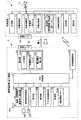
図1は、受信機能を有する電子機器として適用した携帯電話機と、この携帯電話機を充電する充電装置の基本的な構成要素を示したブロック図である。
充電装置1は、無接点充電方式(非接触充電方式)、例えば、電磁誘導方式によって、携帯電話機2に対する充電を行うもので、商用電源(図示省略)などに電源ケーブル3を介して接続されている。なお、充電装置1は、商用電源との接続に限らず、外部機器(パーソナルコンピュータ、オーディオビジュアル機器など)に接続するようにしてもよい。携帯電話機2は、通話機能(受信機能)を有し、二次電池(例えば、リチウム電池)を電源とするもので、この二次電池への充電時にユーザは、携帯電話機2を充電装置1に接続させる際に、携帯電話機2を充電装置1に載置させるようにしている。この場合、充電装置1と携帯電話機2との接続面(載置面)には、対応する接触センサ4a、4bが配設されている。接触センサ4a、4bは、例えば、感圧センサなどで構成されたもので、携帯電話機2が充電装置1に載置されたことを検出する。(Embodiment 1)
Hereinafter, a first embodiment of the present invention will be described with reference to FIGS.
FIG. 1 is a block diagram showing basic components of a mobile phone applied as an electronic device having a receiving function and a charging device for charging the mobile phone.
The
充電装置1は、充電制御部11を中核とするもので、この充電制御部11は、記憶部12内の各種のプログラムに応じてこの充電装置1の全体動作を制御するもので、中央演算処理装置やメモリ(図示省略)などを有している。記憶部12は、ROM、RAMなどの内部メモリで、プログラム領域とデータ領域とを有し、このプログラム領域には、後述する図3に示す動作手順に応じて本実施形態を実現するためのプログラムが格納されている。また、記憶部12のデータ領域には、この充電装置1の動作に必要な各種の情報が一時記憶されているほか、後述の第2実施形態で使用する受信感度−充電効率テーブルTBLが設けられている。 The charging
充電回路部13は、接触センサ4aによって携帯電話機2が充電装置1に接続(載置)されていることが検出されている状態において、携帯電話機2との間で無接点充電方式(例えば、電磁誘導方式)によって充電を行うもので、充電用一次コイル13aのほか、充電切替部13bなどを有する構成となっている。この充電回路部13内の充電切替部13bは、“通常充電”、“急速充電”、“充電オフ”を切り替えるもので、例えば、スイッチングトランジスタなどによって構成され、充電制御部11は、この充電切替部13bに対して、通常充電指示、急速充電指示、充電オフ指示のいずれかを与えることによって“通常充電”、“急速充電”、“充電オフ”のいずれかに切り替えるようにしている。ここで、“急速充電”とは、例えば、“通常充電”で1〜2時間要していた充電を10分〜15分で行う充電方式で、低効率(第1の充電効率)の“通常充電”に対して、高効率(第2の充電効率)の充電方式である。 The charging
非接触通信部14は、接触センサ4aによって携帯電話機2が充電装置1に接続(載置)されていることが検出されている状態において、携帯電話機2との間で非接触通信によってデータの送受信を行うもので、例えば、非接触ICカード、Bluetooth(登録商標)、赤外線通信などの非接触タイプの近距離通信手段によって構成されている。充電制御部11は、携帯電話機2側から充電を制御するための制御情報として、非接触通信部14を介して電池残量、受信状況(後述する受信感度、通話頻度)を取得すると、この電池残量、受信状況に基づいて充電回路部13内の充電切替部13bを制御して、“通常充電”、“急速充電”、“充電オフ”の切り替えを行うようにしている。 The
その他、計時部15は、日時情報を計時したり、各種のタイミング信号(例えば、携帯電話機2から電池残量を受信取得するタイミング、後述する第2実施形態では、携帯電話機2から受信感度を受信取得するタイミング)を生成したりする。報知部16は、充電状態を報知するLED(発光ダイオード)などであり、“通常充電”、“急速充電”、“充電オフ”の状態をその発光色を変えたり、点滅状態を変えたりすることによって識別可能に報知する。操作部17には電源オン/オフキーなどが備えられている。 In addition, the
電子機器としての携帯電話機2は、充電装置1から発生された電力エネルギーの供給によって充電されるもので、次のように構成されている。すなわち、携帯電話機2は、受信機能としての通話機能、電子メール機能、インターネット接続機能(Webアクセス機能)などが備え、最寄りの基地局(図示省略)を介して他の携帯電話機(図示省略)に接続されると、この他の携帯電話機との間で通話可能な状態となり、また、無線通信網を介してインターネット(図示省略)に接続されると、電子メールの送受信が可能となったり、Webページを閲覧可能となったりする。中央制御部21は、電池部22からの電力供給によって動作し、記憶部23内の各種のプログラムに応じてこの携帯電話機2の全体動作を制御するもので、この中央制御部21にはCPU(中央演算処理装置)やメモリなどが設けられている。 The mobile phone 2 as an electronic device is charged by the supply of power energy generated from the charging
電池部22は、接触センサ4bによって携帯電話機2が充電装置1に接続(載置)されていることが検出されている状態において、充電装置1との間で無接点充電方式(例えば、電磁誘導方式)によって充電が行われるもので、二次電池22a、充電用二次コイル22bのほか、電池電圧検出部22cを有する構成となっている。この電池部22内の電池電圧検出部22cは、二次電池22aの電圧をデジタル値(電池電圧値)に変換するもので、中央制御部21は、二次電池22aの放電特性によって決められている複数の電圧範囲内のいずれかに電池電圧値が含まれているかに応じて電池残量(%)を検出するようにしている。 The
記憶部23は、ROM、RAMなどの内部メモリで、プログラム領域とデータ領域とを有し、このプログラム領域には、本実施形態を実現するためのプログラムが格納されている。また、記憶部23のデータ領域には、この携帯電話機2の動作に必要な各種の情報が一時記憶されているほか、通話履歴メモリTLMなどが設けられている。なお、記憶部23は、例えば、SDカード、ICカードなど、着脱自在な可搬型メモリ(記録メディア)を含む構成であってもよく、図示しない所定の外部サーバ上にあってもよい。アプリ処理関係部24は、通話機能、電子メール機能、インターネット接続機能などのアプリケーション処理に関する情報を記憶したり、その処理に関する制御を行ったりする。 The
この通話履歴メモリTLMは、着信毎に着信日時、通話相手の電話番号、通話時間などからなる着信履歴情報と、発信毎に発信日時、通話相手の電話番号、通話時間などからなる発信履歴情報を記憶する構成となっている。中央制御部21は、通話履歴メモリTLM内の着信履歴情報及び発信履歴情報を解析することによって所定期間当たりの着信回数及び発信回数を合計した合計値を通話頻度(受信頻度)として求めるようにしている。このようにして求められた通話頻度(受信頻度)は、充電装置1からの送信要求に応答して、受信機能(通話機能)の受信状況として充電装置1側に送信される情報である。 This call history memory TLM stores incoming call history information including the incoming date and time, the telephone number of the other party of the call, and the call time for each incoming call, and outgoing call history information including the outgoing date and time, the telephone number of the other party of the call, and the call time for each outgoing call. It has a configuration to memorize. The
無線通信部25は、図示しない無線部、ベースバンド部、多重分離部などを備え、例えば、通話機能、電子メール機能、インターネット接続機能などの動作時に、最寄りの基地局との間でデータの送受信を行うもので、通話機能の動作時にはベースバンド部の受信側から信号を取り込んで受信ベースバンド信号に復調したのち、音声信号処理部26を介して通話用スピーカSPから音声出力させ、また、通話用マイクMCからの入力音声データを音声信号処理部26から取り込み、送信ベースバンド信号に符号化した後、ベースバンド部の送信側に与えてアンテナANから発信出力させる。また、無線通信部25には、アンテナANによって受信した信号の電波の強さに基づいて受信感度(受信状況)を検出する受信感度検出部25aが設けられている。この受信感度検出部25aによって検出された受信感度は、充電装置1からの送信要求に応答して、受信機能(通話機能)の受信状況として充電装置1側に送信される情報である。 The
表示部27は、高精細液晶や有機ELを使用し、例えば、待受画像、アイコン、日時情報のほか、テキストデータ、メール、Webページなどを表示する。なお、表示部27は携帯電話機1に備えられている表示部としたが、外部モニタなど、任意の外部表示装置であってもよい。操作部28は、電源オン/オフキー、ダイヤル入力、文字入力、コマンド入力などを入力するもので、中央制御部21は、この操作部28からの入力操作信号に応じた処理を実行する。 The
非接触通信部29は、接触センサ4bによって携帯電話機2が充電装置1に接続(載置)されていることが検出されている状態において、充電装置1との間で非接触通信によってデータの送受信を行うもので、例えば、非接触ICカード、Bluetooth(登録商標)、赤外線通信などの非接触タイプの近距離通信手段によって構成されている。中央制御部21は、この非接触通信部29から充電装置1に対して、充電を制御するための制御情報として充電開始指示を送信するようにしている。 The
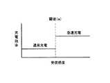
図2は、受信感度に応じて充電効率を切り替える様子を示した図である。
この図は、その横軸を受信感度に対応させ、縦軸を充電効率に対応させたグラフで、受信感度上の所定点は、充電効率を切り替える閾値(a)であることを示している。図示の例は、携帯電話機2側での受信感度が低く閾値(a)未満の場合には、通常充電(低効率充電)が行われることを示し、受信感度が高く閾値(a)以上の場合には、充電効率が切り替えられて、急速充電(高効率充電)が行われることを示している。このように受信状況である受信感度が低い場合には通常充電が行われ、受信感度が高い場合には急速充電が行われ、また、他の受信状況である通話頻度が高い場合には通常充電が行われ、通話頻度が低い場合には急速充電が行われる。FIG. 2 is a diagram illustrating how charging efficiency is switched according to reception sensitivity.
This figure is a graph in which the horizontal axis corresponds to the reception sensitivity and the vertical axis corresponds to the charging efficiency, and the predetermined point on the reception sensitivity indicates the threshold (a) for switching the charging efficiency. The illustrated example indicates that normal charging (low efficiency charging) is performed when the reception sensitivity on the mobile phone 2 side is low and less than the threshold value (a), and when the reception sensitivity is high and the threshold value (a) or more. Indicates that the charging efficiency is switched and quick charging (high efficiency charging) is performed. In this way, when the reception sensitivity is low, normal charging is performed, when the reception sensitivity is high, quick charging is performed, and when the reception frequency is high in other reception conditions, normal charging is performed. When the call frequency is low, quick charging is performed.
次に、第1実施形態における充電装置1の動作概念を図3に示すフローチャートを参照して説明する。ここで、このフローチャートに記述されている各機能は、読み取り可能なプログラムコードの形態で格納されており、このプログラムコードにしたがった動作が逐次実行される。また、ネットワークなど伝送媒体を介して伝送されてきた上述のプログラムコードに従った動作を逐次実行することもできる。このことは後述する他の実施形態においても同様であり、記録媒体のほかに、伝送媒体を介して外部供給されたプログラム/データを利用して本実施形態特有の動作を実行することもできる。 Next, the operation concept of the
図3は、充電装置1の全体動作の概要を示したフローチャートである。
先ず、充電装置1側において充電制御部11は、操作部17の電源オン/オフキーによって電源オン操作が行われると(ステップA1でYES)、携帯電話機2が接続(載置)されたか否かの検出を行いながら接続が検出されるまで待ち状態となる(ステップA2)。すなわち、接触センサ4aによって携帯電話機2が充電装置1に接続(載置)されたことが検出されているときには(ステップA2でYES)、携帯電話機2からの充電開始指示を受信したかを調べ(ステップA3)、充電開始指示を受信するまで上述のステップA2に戻って待機状態となる。ここで、携帯電話機2側では、接触センサ4bによって充電装置1に接続(載置)されたことが検出されると、非接触通信部29を介して充電装置1に対して充電開始指示を与える。FIG. 3 is a flowchart showing an outline of the overall operation of the charging
First, on the
充電装置1は、非接触通信部14を介して携帯電話機2からの充電開始指示を受信すると(ステップA3でYES)、携帯電話機2に対して電池残量の送信要求を行う(ステップA4)。ここで、携帯電話機2側では、この電池残量の送信要求に応答して、電池電圧検出部22cからの電圧値に基づいて電池残量(%)を検出し、この電池残量を非接触通信部29から充電装置1に対して送信する。充電装置1は、非接触通信部14を介して携帯電話機2からの電池残量を受信取得すると(ステップA5)、この電池残量は予め決められている閾値(b1)以下であるか、つまり、満充電(フル充電)状態、例えば、“95%以上”の充電状態に達していないかを調べ(ステップA6)、閾値(b1)を超えてほぼ満充電の状態に達していれば(ステップA6でNO)、今回の充電開始指示を無効とするために上述のステップA2に戻る。 When the
また、電池残量が閾値(b1)以下であれば、つまり、ほぼ満充電の状態に達していなければ(ステップA6でYES)、更に、電池残量は予め決められている閾値(b2)以上であるか、つまり、電池残量が不足間際となる10%を基準とした場合に、この10%以上であるかを調べ(ステップA7)、10%未満であれば(ステップA7でNO)、携帯電話機2の通話機能を使用可能な状態に維持するために直ちに急速充電が必要であると判断して、ステップA20に移り、充電回路部13内の充電切替部13bに対して急速充電指示を与え、急速充電が可能な状態に切り替えて急速充電を開始させる。この場合、報知部16を駆動して急速充電中であることを、例えば、赤色発光によって報知させる。 If the remaining battery level is equal to or less than the threshold value (b1), that is, if the battery is not almost fully charged (YES in step A6), the remaining battery level is equal to or greater than a predetermined threshold value (b2). In other words, if the remaining battery level is 10%, which is about to be insufficient, whether it is 10% or more is checked (step A7), and if less than 10% (NO in step A7), It is determined that quick charging is necessary immediately in order to maintain the calling function of the mobile phone 2 in a usable state, the process proceeds to step A20, and a quick charging instruction is given to the
このようにして急速充電を開始させた後、充電制御部11は、計時部15で生成された電池残量取得タイミングに達したかを調べる(ステップA21)。例えば、1分間隔で電池残量を取得する場合には前回取得から1分経過したかを調べながら電池残量取得タイミングに達するまで待機するが、その取得タイミングに達したときには(ステップA21でYES)、携帯電話機2に対して電池残量の送信要求を行い(ステップA22)、これに応答して携帯電話機2側からの電池残量を受信すると(ステップA23)、電池残量は100%に達したかを調べる(ステップA24)。ここで、電池残量が100%未満であれば(ステップA24でNO)、100%に達するまで上述のステップA20に戻って急速充電を継続するが、100%に達したときには(ステップA24でYES)、充電回路部13内の充電切替部13bに対して充電オフ指示を与え、充電オフ状態に切り替えて充電を終了させる(ステップA25)。その後、上述のステップA2に戻る。 After starting the quick charge in this way, the
一方、電池残量が10%以上95%以下の範囲内の場合(ステップA7でYES)、充電装置1は、携帯電話機2に対して受信感度の送信要求を行う(ステップA8)。ここで、携帯電話機2側では、この受信感度の送信要求に応答して、無線通信部25の受信感度検出部25aで検出された受信感度を現在の受信状況を示す情報として充電装置1に送信する。充電装置1は、非接触通信部14を介して携帯電話機2からの受信感度を受信取得すると(ステップA9)、この受信感度と予め決められている閾値(a)とを比較し、閾値(a)未満であるかを調べ(ステップA10)、受信感度が閾値(a)以上であれば(ステップA10でNO)、急速充電を行ったとしても受信感度への悪影響は少ない、つまり、ある程度の受信感度があれば、急速充電を行っても受信感度への悪影響(感度の低下)を低く抑えることができると判断して、上述のステップA20に移り、急速充電を開始させる。 On the other hand, when the remaining battery level is in the range of 10% or more and 95% or less (YES in step A7), charging
また、受信感度が閾値(a)未満の場合には(ステップA10でYES)、充電装置1は、携帯電話機2に対して受信履歴の送信要求を行う(ステップA11)。ここで、携帯電話機2側では、この受信履歴の送信要求に応答して、通話履歴メモリTLMの内容を解析することによって通話機能を使用した通話頻度を求める。すなわち、所定期間(例えば2週間)内の着信履歴情報から着信回数を求めると共に発信履歴情報から発信回数を求めて、この所定期間当たりの着信回数と発信回数とを合計した合計値を通話頻度として求め、この通話頻度を充電装置1に対して送信する。充電装置1は、非接触通信部14を介して携帯電話機2からの通話頻度を受信取得すると(ステップA12)、この通話頻度と予め決められている閾値(c)とを比較し、通話頻度は、閾値(c)以上であるかを調べ(ステップA13)、閾値(c)未満であれば(ステップA13でNO)、急速充電を行ったとしても受信感度への悪影響は少ない、つまり、通話頻度が多くない場合には、受信感度への悪影響(感度の低下)よりも充電時間の短縮化を優先させるために、上述のステップA20に移り、急速充電を開始させる。 If the reception sensitivity is less than the threshold value (a) (YES in step A10), the charging
また、通話頻度が閾値(c)以上であれば(ステップA13でYES)、受信感度への悪影響(感度の低下)が大きいと判断して、ステップA14に移り、充電回路部13内の充電切替部13bに対して通常充電指示を与え、通常充電が可能な状態に切り替えて通常充電を開始させる。この場合、報知部16を駆動して通常充電中であることを、例えば、青色発光によって報知させる。このように通常充電を開始した後に充電制御部11は、計時部15で生成された電池残量取得タイミングに達したかを調べる(ステップA15)。例えば、1分間隔で電池残量を取得する場合には前回取得から1分経過したかを調べながら電池残量取得タイミングに達するまで待機する。 If the call frequency is equal to or higher than the threshold value (c) (YES in step A13), it is determined that the adverse effect on the reception sensitivity (decrease in sensitivity) is large, the process proceeds to step A14, and charge switching in the charging
ここで、電池残量取得タイミングに達したときには(ステップA15でYES)、携帯電話機2に対して電池残量の送信要求を行い(ステップA16)、これに応答して携帯電話機2側から電池残量を受信すると(ステップA17)、電池残量は100%に達したかを調べ(ステップA18)、電池残量が100%未満であれば(ステップA18でNO)、100%に達するまで上述のステップA14に戻って通常充電を継続するが、100%に達したときには(ステップA18でYES)、充電回路部13内の充電切替部13bに対して充電オフ指示を与え、充電オフ状態に切り替えて充電を終了させる(ステップA19)。その後、上述のステップA2に戻る。 Here, when the battery remaining amount acquisition timing is reached (YES in step A15), a request for transmitting the remaining battery amount is sent to the mobile phone 2 (step A16), and in response to this, the remaining battery amount is sent from the mobile phone 2 side. When the amount is received (step A17), it is checked whether the remaining battery level has reached 100% (step A18). If the remaining battery level is less than 100% (NO in step A18), the above-described process is performed until it reaches 100%. Returning to step A14, normal charging is continued, but when 100% is reached (YES in step A18), a charge off instruction is given to the
以上のように、第1実施形態において充電装置1は、携帯電話機2の無線通信部25から取得した受信状況に基づいて充電回路部13の充電効率を変更するようにしたので、受信に対する影響度と充電時間のバランスを考慮した適切な充電制御を実現することができ、実情に即し、実用性に富んだものとなる。 As described above, in the first embodiment, the charging
充電装置1は、携帯電話機2からその受信状況として取得した受信感度に基づいて充電回路部13の充電効率を変更するようにしたので、充電中に発生するノイズによって携帯電話機2の受信感度が低下することを極力抑えることができる。この場合、受信に対する影響度と充電時間のバランスを考慮して、受信感度が悪い場合には低効率の充電で受信感度の劣化を抑えるのに対し、受信感度が良い場合には充電時間を優先させるために高効率の充電を行うことでバランスの良い充電が可能となる。 Since the
充電装置1は、受信感度と所定の閾値とを比較した結果、この閾値より受信感度が悪い場合には第1の充電効率の通常充電を行わせ、閾値より受信感度が良い場合には第2の充電効率の急速充電を行わせるようにしたので、段階的な制御(2段階切り替え)が可能となる。 As a result of comparing the reception sensitivity with a predetermined threshold, the charging
充電装置1は、携帯電話機2からその受信状況として取得した通話頻度に基づいて充電回路部13の充電効率を変更するようにしたので、受信に対する影響度と充電時間のバランスを考慮して、通話頻度が多い場合には低効率の充電で受信感度の劣化を抑えるのに対し、通話頻度が少ない場合には充電時間を優先させるために高効率の充電を行うことでバランスの良い充電が可能となる。 Since the
充電装置1は、携帯電話機2から取得した受信感度及び通話頻度に基づいて充電回路部13の充電効率を変更するようにしたので、例えば、受信感度が悪く、通話頻度が多い場合には、低効率の充電で受信感度の劣化を抑えるのに対し、受信感度が良く、通話頻度が少ない場合には高効率の充電を優先させることができ、より一層、木目細かな制御が可能となる。 Since the
充電装置1は、携帯電話機2から取得した受信状況と電池残量に基づいて充電回路部13の充電効率を変更するようにしたので、例えば、電池残量が不足間際であれば、受信状況にかかわらず、携帯電話機2の通話機能を使用可能な状態に維持するために高効率の充電を優先させるが、電池残量が不足していなければ、受信状況に応じて充電効率を変更することができる。 Since the
充電装置1は、無接点充電方式によって前記電子機器に対して充電を行うようにしたので、特に充電装置1の影響が出やすい無接点充電方式に対して、好適に採用することができる Since the
(実施形態2)
以下、この発明の第2実施形態について図4〜図6を参照して説明する。
なお、上述した第1実施形態においては、充電効率として通常充電と急速充電の2種類を例示したが、この第2実施形態においては、受信感度−充電効率テーブルTBLを参照し、4種類の充電効率の中からそのいずれかを現在の受信状況に基づいて選択するようにしたものである。ここで、両実施形態において基本的あるいは名称的に同一のものは、同一符号を付して示し、その説明を省略すると共に、以下、第2実施形態の特徴部分を中心に説明するものとする。(Embodiment 2)
A second embodiment of the present invention will be described below with reference to FIGS.
In the first embodiment described above, two types of charging efficiency, normal charging and quick charging, are exemplified. In the second embodiment, four types of charging are performed with reference to the reception sensitivity-charging efficiency table TBL. One of the efficiencies is selected based on the current reception status. Here, in both the embodiments, the same or the same names are denoted by the same reference numerals, the description thereof will be omitted, and the following description will focus on the features of the second embodiment. .
図4は、第2実施形態で使用する受信感度−充電効率テーブルTBLを説明するための図である。
受信感度−充電効率テーブルTBLは、携帯電話機2への充電時にその通話機能の受信状況(受信感度)に応じて充電効率を変更する際に参照されるテーブルで、受信感度」、「充電効率」の項目を有している。なお、図示の例では、「受信感度」には、受信感度が最も悪い“閾値(a1)未満”から受信感度が最も良い“閾値(a3)以上”が記憶されている。また、「充電効率」には、受信感度が最も悪い“閾値(a1)未満”に対応して、最も低い充電効率(低速充電)である“充電効率(1)”が記憶され、また、受信感度が最も良い“閾値(a3)以上”に対応して、最も高い充電効率(高速充電)である“充電効率(4)”が記憶されている。FIG. 4 is a diagram for explaining a reception sensitivity-charge efficiency table TBL used in the second embodiment.
The reception sensitivity-charge efficiency table TBL is a table that is referred to when the charge efficiency is changed according to the reception status (reception sensitivity) of the call function when the mobile phone 2 is charged. Have items. In the illustrated example, “reception sensitivity” stores “less than threshold (a1)” having the lowest reception sensitivity to “more than threshold (a3)” having the highest reception sensitivity. Further, “charging efficiency” stores “charging efficiency (1)” that is the lowest charging efficiency (low-speed charging) corresponding to “less than threshold (a1)” having the lowest receiving sensitivity. Corresponding to “threshold (a3) or higher” having the best sensitivity, “charging efficiency (4)” which is the highest charging efficiency (fast charging) is stored.
一方、「受信感度」としては、受信感度が“閾値(a1)未満”の次に悪い“閾値(a1)以上閾値(a2)未満”が記憶され、また、受信感度が“閾値(a3)以上”の次に良い“閾値(a2)以上閾値(a3)未満”が記憶されている。そして、「充電効率」には、受信感度が次に悪い“閾値(a1)以上閾値(a2)未満”に対応して、“充電効率(1)”の次に低い充電効率である“充電効率(2)”が記憶され、また、受信感度が次に良い“閾値(a2)以上閾値(a3)未満”に対応して、“充電効率(4)”の次に高い充電効率である“充電効率(3)”が記憶されている。 On the other hand, as the “reception sensitivity”, the next worst “threshold (a1) or more and less than threshold (a2)” is stored, and the reception sensitivity is “threshold (a3) or more”. “Next to“ threshold (a2) or more and less than threshold (a3) ”is stored. “Charging efficiency” corresponds to “threshold (a1) or more and less than threshold (a2)” with the next lowest reception sensitivity, and “charging efficiency” is the next lowest charging efficiency after “charging efficiency (1)”. “(2)” is stored and “Charging efficiency” is the next highest charging efficiency after “Charging efficiency (4)” corresponding to “Threshold (a2) or more and less than threshold (a3)” with the next best reception sensitivity. Efficiency (3) "is stored.
図5は、第2実施形態において、受信感度に応じて充電効率を切り替える様子を示した図である。
この図は、その横軸を受信感度に対応させ、縦軸を充電効率に対応させたグラフで、受信感度上の所定点は、充電効率を切り替える閾値(a1)、(a2)、(a3)であることを示している。図示の例は、「受信感度」が“閾値(a1)未満”の場合には、“充電効率(1)”の充電が行われることを示し、“閾値(a1)以上閾値(a2)未満”の場合には、“充電効率(2)”の充電が行われることを示し、“閾値(a2)以上閾値(a3)未満”の場合には、“充電効率(3)”の充電が行われることを示し、“閾値(a3)以上”の場合には、“充電効率(4)”の充電が行われることを示している。これに応じて第2実施形態の充電切替部13bは、受信感度に応じて“充電効率(1)”、“充電効率(2)”、“充電効率(3)”、“充電効率(4)”、“充電オフ”に切り替え可能な構成となっている。FIG. 5 is a diagram showing how charging efficiency is switched according to reception sensitivity in the second embodiment.
This figure is a graph in which the horizontal axis corresponds to the reception sensitivity and the vertical axis corresponds to the charging efficiency. The predetermined points on the reception sensitivity are threshold values (a1), (a2), (a3) for switching the charging efficiency. It is shown that. In the example shown in the figure, when “reception sensitivity” is “less than threshold (a1)”, charging of “charging efficiency (1)” is performed, and “threshold (a1) or more and less than threshold (a2)”. In this case, it indicates that charging with “charging efficiency (2)” is performed, and when “threshold (a2) or more and less than threshold (a3)”, charging with “charging efficiency (3)” is performed. In the case of “threshold (a3) or more”, it indicates that charging with “charging efficiency (4)” is performed. In response to this, the
図6は、第2実施形態において充電装置1の全体動作の概要を示したフローチャートである。
先ず、充電制御部11は、図3のフローチャートと同様に、操作部17の電源オン/オフキーによって電源オン操作が行われると(ステップB1でYES)、携帯電話機2が接続(載置)されたか否かの検出を行いながら載置されるまで待ち状態となる(ステップB2)。いま、携帯電話機2が充電装置1に接続(載置)されたことを接触センサ4aが検出したときには(ステップB2でYES)、携帯電話機2からの充電開始指示を受信したかを調べ(ステップB3)、充電開始指示を受信するまで上述のステップB2に戻って待機状態となる。いま、携帯電話機2からの充電開始指示を受信すると(ステップB3でYES)、携帯電話機2に対して電池残量の送信要求を行い(ステップB4)、これに応答して携帯電話機2からの電池残量を受信取得すると(ステップB5)、電池残量は予め決められている閾値(b1)以下であるか、つまり、満充電(フル充電)状態かを調べ(ステップB6)、満充電状態に達していれば(ステップB6でNO)、今回の充電開始指示を無効とするために上述のステップB2に戻る。FIG. 6 is a flowchart showing an outline of the overall operation of the
First, as in the flowchart of FIG. 3, when the power-on operation is performed by the power-on / off key of the operation unit 17 (YES in Step B <b> 1), the charging
また、電池残量が閾値(b1)以下であれば、つまり、満充電状態に達していなければ(ステップB6でYES)、充電装置1は、携帯電話機2に対して受信感度の送信要求を行い(ステップB7)、これに応答して携帯電話機2から送信された受信感度を受信取得すると(ステップB8)、この受信感度に基づいて受信感度−充電効率テーブルTBLを参照することによって(ステップB9)、この受信感度に該当する「充電効率」を決定する(ステップB10)。この場合、受信感度が“閾値(a1)未満”であれば、“充電効率(1)”を決定し、“閾値(a1)以上閾値(a2)未満”であれば、“充電効率(2)”を決定し、“閾値(a2)以上閾値(a3)未満”であれば、“充電効率(3)”を決定し、“閾値(a3)以上”であれば、“充電効率(4)”を決定する。 If the remaining battery level is equal to or less than the threshold (b1), that is, if the battery is not fully charged (YES in step B6), charging
これによって決定した充電効率に基づいて充電切替部13bを制御し、“充電効率(1)”、“充電効率(2)”、“充電効率(3)”、“充電効率(4)”のいずれかに切り替えることによって、その充電効率に応じた充電を開始させる(ステップB11)。この場合、報知部16を駆動して充電効率を、例えば、発光色を変えることで報知させる。そして、このようにして充電を開始させた後に充電制御部11は、携帯電話機2に対して電池残量の送信要求を行い(ステップB12)、これに応答して携帯電話機2側から送信された電池残量を受信すると(ステップB13)、この電池残量は100%未満であるかを調べ(ステップB14)、電池残量が100%に達したときには(ステップB14でNO)、充電回路部13内の充電切替部13bに対して充電オフ指示を与え、充電オフ状態に切り替えて充電を終了させる(ステップB15)。その後、上述のステップB2に戻る。 Based on the charging efficiency determined thereby, the
また、電池残量が100%未満であれば(ステップB14でYES)、計時部15で生成された受信感度取得タイミングに達したかを調べる(ステップB16)。例えば、1分間隔で受信感度を取得する場合には前回取得から1分経過したかを調べ、受信感度取得タイミングに達していなければ(ステップB16でNO)、同一の充電効率で充電を継続させるために、上述のステップB11に戻る。また、受信感度取得タイミングに達したときには(ステップB16でYES)、上述のステップB7に戻って、再度、携帯電話機2に対して受信感度の送信要求を行い、これに応答して携帯電話機2から送信された受信感度を受信取得すると(ステップB8)、この受信感度に基づいて受信感度−充電効率テーブルTBLを参照し(ステップB9)、充電効率を変更するときには新たな充電効率を決定し(ステップB10)、この充電効率に応じた充電に切り替える(ステップB11)。このような動作を繰り返すことによって充電効率は、受信感度の変化に逐次追随しながら順次変更される。ここで、電池残量が100%に達したときには(ステップB14でYES)、充電を終了させた後(ステップB15)、上述のステップB2に戻る。 If the remaining battery level is less than 100% (YES in step B14), it is checked whether the reception sensitivity acquisition timing generated by the
以上のように、第2実施形態において充電装置1は、携帯電話機2から取得した受信感度の変化に逐次追随して充電回路部13の充電効率を順次変更するようにしたので、受信に対する影響度と充電時間のバランスを考慮した適切な充電制御を実現することができると共に、木目細かな充電制御が可能となる。この場合、受信感度に応じて受信感度−充電効率テーブルTBLを参照することで、充電効率を4段階に制御することが可能となる。 As described above, in the second embodiment, the charging
充電装置1は、携帯電話機2から受信状況を定期的に取得して充電効率を変更するようにしたので、受信状況が頻繁に変化している場合でも、受信状況取得タイミングに合わせて充電効率を変更することができる。 Since the
なお、上述した第2実施形態においては、受信感度に応じて受信感度−充電効率テーブルTBLを参照することによって、充電効率を4段階で制御するようにしたが、受信感度に応じて4段階以上の多段階(例えば、6段階、8段階、10段階など)で制御したり、無段階で制御したりするようにしてもよい。この場合、図7に示すように、受信感度の変化に逐次追随しながら充電効率を曲線的に滑らかに変更させるようにしてもよい。このように充電効率を受信感度の変化に曲線的に追随させることによって、より一層、木目細かな充電制御が可能となる。 In the second embodiment described above, the charging efficiency is controlled in four stages by referring to the reception sensitivity-charging efficiency table TBL in accordance with the reception sensitivity. However, in four or more stages in accordance with the reception sensitivity. The control may be performed in multiple stages (for example, 6 stages, 8 stages, 10 stages, etc.), or may be controlled in a stepless manner. In this case, as shown in FIG. 7, the charging efficiency may be smoothly changed in a curved manner while sequentially following the change in the reception sensitivity. In this way, by making the charging efficiency follow the change in the reception sensitivity in a curved line, it becomes possible to perform charging control more finely.
上述した第2実施形態においては、受信感度−充電効率テーブルTBLを設けた構成としたが、更に、通話頻度(受信頻度)−充電効率テーブルを設けるようにしてもよい。この場合、例えば、充電効率を切り替える通話頻度の閾値を(c1)、(c2)、(c3)とすると、通話頻度の“閾値(c1)未満”に対応して、高い充電効率(高速充電)である“充電効率(4)”を記憶し、“閾値(c1)以上閾値(c2)未満”
に対応して、“充電効率(4)”の次に高い充電効率である“充電効率(3)”、“閾値(c2)以上閾値(c3)未満”に対応して、“充電効率(1)”の次に低い充電効率である“充電効率(2)”、“閾値(c3)以上”に対応して、最も低い充電効率(低速充電)である“充電効率(1)”を記憶するようにすればよい。In the second embodiment described above, the reception sensitivity-charge efficiency table TBL is provided. However, a call frequency (reception frequency) -charge efficiency table may be further provided. In this case, for example, if the threshold values of the call frequency for switching the charging efficiency are (c1), (c2), and (c3), the charging frequency is high (high-speed charging) corresponding to “less than the threshold value (c1)”. “Charging efficiency (4)” is stored, and “more than threshold (c1) and less than threshold (c2)”
Corresponding to “charging efficiency (4)”, “charging efficiency (3)”, “threshold (c2) or more and less than threshold (c3)”, “charging efficiency (1) ) "Charging efficiency (1)" that is the lowest charging efficiency (low-speed charging) is stored corresponding to "charging efficiency (2)" that is the next lowest charging efficiency, and "threshold (c3) or more" What should I do?
(実施形態3)
以下、この発明の第3実施形態について図8を参照して説明する。
なお、上述した第1及び第2実施形態においては、充電装置1について適用した場合で、この充電装置1は、携帯電話機2の無線通信部25から取得した受信状況に基づいて充電回路部13の充電効率を変更するようにしたが、この第3実施形態においては、電子機器の携帯電話機2に適用した場合で、携帯電話機2は、無線通信部25の受信状況に基づいて充電装置1に充電効率の変更を指示するようにしたものである。ここで、第1・第3実施形態において基本的あるいは名称的に同一のものは、同一符号を付して示し、その説明を省略すると共に、以下、第3実施形態の特徴部分を中心に説明するものとする。(Embodiment 3)
A third embodiment of the present invention will be described below with reference to FIG.
In the first and second embodiments described above, when applied to the
図8は、第3実施形態において携帯電話機2側の全体動作の概要と実施形態の特徴的な動作を示したフローチャートである。
先ず、携帯電話機2において中央制御部21は、操作部28の電源オン/オフキーによって電源オン操作が行われると(ステップC1でYES)、電話着信を検出したかを調べたり(ステップC2)、電話発信を検出したかを調べたり(ステップC5)、何らかの操作が行われたかを調べたり(ステップC8)、携帯電話機2が充電装置1に接続(載置)されたかを調べたりする(ステップC10)。FIG. 8 is a flowchart showing an overview of the overall operation on the mobile phone 2 side and the characteristic operation of the embodiment in the third embodiment.
First, in the cellular phone 2, when the power-on operation is performed by the power-on / off key of the operation unit 28 (YES in step C1), the
いま、電話着信を検出したときには(ステップC2でYES)、通話可能状態とする通話処理を行うと共に(ステップC3)、今回の着信情報を通話履歴メモリTLMに着信履歴として登録する(ステップC4)。また、電話発信を検出したときには(ステップC5でYES)、通話可能状態とする通話処理を行うと共に(ステップC6)、今回の発信情報を通話履歴メモリTLMに発信履歴として登録する(ステップC7)。また、何らかの操作が行われたときには(ステップC8でYES)、例えば、メール送信処理、インターネット接続処理など、その操作に応じた処理が行われる(ステップC9)。 If an incoming call is detected (YES in step C2), call processing for enabling a call is performed (step C3), and the current incoming information is registered in the call history memory TLM as an incoming call history (step C4). When a call transmission is detected (YES in step C5), call processing for enabling a call is performed (step C6), and the current call information is registered in the call history memory TLM as a call history (step C7). Further, when any operation is performed (YES in step C8), for example, processing corresponding to the operation such as mail transmission processing and Internet connection processing is performed (step C9).
また、接触センサ4bが充電装置1に接続(載置)されたことを検出したときには(ステップC10でYES)、電池部22の電池電圧検出部22cで電池電圧を検出し、その電池電圧から対応する電池残量を取得し(ステップC11)、電池残量は予め決められている閾値(b1)以下であるか、つまり、満充電(フル充電)状態、例えば、“95%以上”の充電状態に達していないかを調べる(ステップC12)。ここで、電池残量が閾値(b1)を超えて満充電状態に達していれば(ステップC12でNO)、今回の充電を無効とするために上述のステップC2に戻る。 Further, when it is detected that the
電池残量が閾値(b1)以下であれば、つまり、満充電状態に達していなければ(ステップC12でYES)、更に、電池残量は閾値(b2)以上であるか、つまり、電池残量が不足間際となる10%を基準とした場合に、この10%以上であるかを調べ(ステップC13)、10%未満であれば(ステップC13でNO)、携帯電話機2の通話機能を使用可能な状態に維持するために直ちに急速充電が必要であると判断して、ステップC22に移り、非接触通信部29を介して充電装置1に急速充電指示を送信する。この場合、充電装置1側では、この急速充電指示に応じて充電回路部13内の充電切替部13bを制御して、急速充電を開始させる。 If the remaining battery level is not more than the threshold (b1), that is, if the battery is not fully charged (YES in step C12), the remaining battery level is not less than the threshold (b2), that is, the remaining battery level. When 10%, which is short of the shortage, is used as a reference, it is checked whether it is 10% or more (step C13). If it is less than 10% (NO in step C13), the call function of the mobile phone 2 can be used. If it is determined that rapid charging is necessary immediately in order to maintain this state, the process proceeds to step C22, and a rapid charging instruction is transmitted to the
そして、携帯電話機2側では、急速充電中において電池残量取得タイミングに達したかを調べる(ステップC23)。例えば、1分間隔で電池残量を取得する場合には前回取得から1分経過したかを調べ、電池残量取得タイミングに達するまで待機するが、その取得タイミングに達したときには(ステップC23でYES)、電池残量は100%に達したかを調べる(ステップC24)。ここで、100%に達しなければ(ステップC24でNO)、100%に達するまで上述のステップC23に戻って急速充電を継続させるが、100%に達したときには(ステップC24でYES)、充電装置1に対して充電オフ指示を与えて急速充電を終了させる(ステップC25)。その後、上述のステップC2に戻る。 Then, on the mobile phone 2 side, it is checked whether the battery remaining amount acquisition timing has been reached during the quick charging (step C23). For example, when the remaining battery level is acquired at 1-minute intervals, it is checked whether 1 minute has elapsed since the previous acquisition, and waits until the remaining battery level acquisition timing is reached, but when the acquired timing is reached (YES in step C23) ), It is checked whether the remaining battery level has reached 100% (step C24). Here, if it does not reach 100% (NO in step C24), the process returns to step C23 described above until it reaches 100% and the rapid charging is continued, but when it reaches 100% (YES in step C24), the charging
一方、電池残量が10%以上95%以下の範囲内にある場合には(ステップC13でYES)、無線通信部25の受信感度検出部25aで検出された受信感度を取得し(ステップC14)、この受信感度と閾値(a)とを比較し、閾値(a)未満であるかを調べる(ステップC15)。ここで、受信感度が閾値(a)以上であれば(ステップC15でNO)、急速充電を行ったとしても受信感度への悪影響は少ない、つまり、ある程度の受信感度があれば、急速充電を行っても受信感度への悪影響(感度の低下)を低く抑えることができると判断して、ステップC22に移り、充電装置1に対して急速充電指示を送信する。 On the other hand, if the remaining battery level is in the range of 10% to 95% (YES in step C13), the reception sensitivity detected by the reception
また、受信感度が閾値(a)未満の場合には(ステップC15でYES)、通話履歴メモリTLMの内容を解析することによって通話機能を使用した通話頻度を求める(ステップC16)。すなわち、所定期間(例えば2週間)内の着信履歴から着信回数を求めると共に発信履歴から発信回数を求めて、この所定期間当たりの着信回数と発信回数とを合計した合計値を通話頻度として求める。そして、この通話頻度と閾値(c)とを比較し、予め決められている閾値(c)以上であるかを調べ(ステップC17)、閾値(c)未満であれば(ステップC17でNO)、急速充電を行ったとしても受信感度への悪影響は少ない、つまり、通話頻度が多くない場合には、受信感度への悪影響(感度の低下)よりも充電時間の短縮化を優先させるためにステップC22に移り、充電装置1に対して急速充電指示を送信する。 If the reception sensitivity is less than the threshold value (a) (YES in step C15), the call frequency using the call function is obtained by analyzing the contents of the call history memory TLM (step C16). That is, the number of incoming calls is obtained from the incoming history within a predetermined period (for example, two weeks) and the number of outgoing calls is obtained from the outgoing history, and the total value of the number of incoming calls and the number of outgoing calls per predetermined period is obtained as the call frequency. Then, the call frequency is compared with the threshold value (c) to check whether it is greater than or equal to a predetermined threshold value (c) (step C17). If it is less than the threshold value (c) (NO in step C17), Even if quick charging is performed, if there is little adverse effect on the reception sensitivity, that is, if the frequency of calls is not high, in order to prioritize the shortening of the charging time over the adverse effect on the reception sensitivity (decrease in sensitivity), step C22 Then, a quick charging instruction is transmitted to the
また、通話頻度が閾値(c)以上であれば(ステップC17でYES)、充電装置1に対して通常充電指示を送信する(ステップC18)。この場合、充電装置1側では、この通常充電指示に応じて充電回路部13内の充電切替部13bを制御して、通常充電を開始させる。そして、この通常充電中において電池残量取得タイミングに達したかを調べる(ステップC19)。例えば、1分間隔で電池残量を取得する場合には前回取得から1分経過したかを調べ、電池残量取得タイミングに達するまで待機するが、その取得タイミングに達したときには(ステップC19でYES)、電池残量は100%に達したかを調べる(ステップC20)。ここで、電池残量が100%未満であれば(ステップC20でNO)、100%に達するまで上述のステップC19に戻って通常充電を継続させるが、100%に達したときには(ステップC20でYES)、充電装置1に対して充電オフ指示を与えて通常充電を終了させる(ステップC21)。その後、上述のステップC2に戻る。 If the call frequency is equal to or higher than the threshold value (c) (YES in step C17), a normal charging instruction is transmitted to charging device 1 (step C18). In this case, the charging
以上のように、第3実施形態において携帯電話機2は、無線通信部25から取得した受信状況に基づいて充電装置1の充電効率の変更を指示するようにしたので、受信に対する影響度と充電時間のバランスを考慮した適切な充電制御を実現することができ、実情に即して、実用性に富んだものとなる。 As described above, in the third embodiment, the mobile phone 2 instructs to change the charging efficiency of the
携帯電話機2は、受信状況として取得した受信感度に基づいて充電装置1の充電効率の変更を指示するようにしたので、充電装置1による充電中に発生するノイズによって受信感度が低下することを極力抑えることができる。この場合、受信に対する影響度と充電時間のバランスを考慮して、受信感度が悪い場合には低効率の充電で受信感度の劣化を抑えるのに対し、受信感度が良い場合には充電時間を優先させるために高効率の充電を行うことでバランスの良い充電が可能となる。 Since the mobile phone 2 instructs to change the charging efficiency of the
携帯電話機2は、通話頻度に基づいて充電装置1の充電効率の変更を指示するようにしたので、受信に対する影響度と充電時間のバランスを考慮して、通話頻度が多い場合には低効率の充電で受信感度の劣化を抑えるのに対し、通話頻度が少ない場合には充電時間を優先させるために高効率の充電を行うことでバランスの良い充電が可能となる。 Since the mobile phone 2 instructs to change the charging efficiency of the
携帯電話機2は、受信感度及び通話頻度に基づいて充電装置1の充電効率の変更を指示するようにしたので、例えば、受信感度が悪く、通話頻度が多い場合には、低効率の充電で受信感度の劣化を抑えるのに対し、受信感度が良く、通話頻度が少ない場合には高効率の充電を優先させることができ、より一層、木目細かな制御が可能となる。 Since the cellular phone 2 is instructed to change the charging efficiency of the
携帯電話機2は、受信状況と電池残量に基づいて充電装置1の充電効率の変更を指示するようにしたので、例えば、電池残量が不足間際であれば、受信状況にかかわらず、通話機能を使用可能な状態に維持するために高効率の充電を優先させるが、電池残量が不足していなければ、受信状況に応じて充電効率を変更させることができる。 Since the mobile phone 2 instructs to change the charging efficiency of the
携帯電話機2は、充電装置1に対して充電効率の変更を指示する変更指示情報を送信するようにしたので、充電効率の変更に応じた充電制御を充電装置1側で実行させることができる。 Since the cellular phone 2 transmits the change instruction information for instructing the
なお、上述した各実施形態においては、携帯電話機2の受信状況として受信感度、通話頻度(所定期間当たりの着信回数及び発信回数を合計した合計値)を示したが、例えば、受信機能の使用累計回数を受信状況としてもよく、電波障害の多い受信場所にあるか否か等の情報を受信状況としてもよい。 In each of the above-described embodiments, the reception sensitivity and the call frequency (the total sum of the number of incoming calls and the number of outgoing calls per predetermined period) are shown as the reception status of the mobile phone 2. The number of times may be used as the reception status, and information such as whether or not the reception location has a lot of radio interference may be used as the reception status.
また、上述した各実施形態においては、無接点充電方式を採用したが、無接点充電方式に限らず、有接点充電方式(接触型充電方式)であってもよい。 Moreover, in each embodiment mentioned above, although the non-contact charge system was employ | adopted, not only a non-contact charge system but a contact point charge system (contact-type charge system) may be sufficient.
また、上述した各実施形態においては、充電装置1と携帯電話機2との接続面(載置面)に、対応する接触センサ4a、4bを配設することによって携帯電話機2が充電装置1に載置されたことを検出するようにしたが、それらの接続の検出は、例えば、電磁誘導作用を利用して検出するようにしてもよい。この場合、電磁誘導作用によって発生された起電力が所定値よりも大きいか否かによって携帯電話機2が充電装置1に載置されたことを検出するようにしてもよい。また、上述した各実施形態においては、充電装置1に携帯電話機2を載置するようにしたが、載置以外の接続として、それらの近接などを検出するようにしてもよい。更には、プラグ、コネクタなどを用いて有線接続し、その検出を検出用端子で行うようにしてもよいことは言うまでもない。 In the above-described embodiments, the mobile phone 2 is mounted on the
上述した各実施形態においては、電池残量を電池電圧に基づいて取得するようにしているが、他の方法(アルゴリズム)で取得するようにしてもよい。 In each of the above-described embodiments, the remaining battery level is acquired based on the battery voltage, but may be acquired by another method (algorithm).
上述した各実施形態においては、電子機器として携帯電話機2に適用した場合を示したが、受信機能付きのPDA、音楽プレイヤー、それらの複合機、又はテレビ放送やラジオ放送を受信する放送受信装置など、任意の装置であってもよい。 In each of the above-described embodiments, a case where the present invention is applied to the mobile phone 2 as an electronic device has been described. However, a PDA with a reception function, a music player, a multi-function device thereof, or a broadcast receiving device that receives a television broadcast or a radio broadcast Any device may be used.
上述した各実施形態において示した“装置”や“機”とは、機能別に複数の筐体に分離されていてもよく、単一の筐体に限らない。また、上述したフローチャートに記述した各ステップは、時系列的な処理に限らず、複数のステップを並列的に処理したり、別個独立して処理したりするようにしてもよい。 The “apparatus” and “machine” shown in each of the above-described embodiments may be separated into a plurality of cases by function, and are not limited to a single case. In addition, each step described in the above-described flowchart is not limited to time-series processing, and a plurality of steps may be processed in parallel or separately.
1 充電装置
2 携帯電話機
4a、4b 接触センサ
11 充電制御部
12 記憶部
13 充電回路部
13a 充電用一次コイル
13b 充電切替部
14 非接触通信部
15 計時部
21 中央制御部
22 電池部
22a 二次電池
22b 充電用二次コイル
22c 電池電圧検出部
23 記憶部
25 無線通信部
25a 受信感度検出部
29 非接触通信部
TBL 受信感度−充電効率テーブル
TLM 通話履歴メモリ
DESCRIPTION OF
Claims (17)
Translated fromJapanese前記電子機器から前記受信機能の受信状況を取得する受信状況取得手段と、
この受信状況取得手段によって取得された受信状況に基づいて、充電効率を変更するように制御する充電制御手段と、
を具備したことを特徴とする充電装置。A charging device for charging an electronic device having a receiving function,
Reception status acquisition means for acquiring the reception status of the reception function from the electronic device;
Based on the reception status acquired by this reception status acquisition means, charging control means for controlling to change the charging efficiency,
A charging device comprising:
前記充電制御手段は、前記受信状況取得手段によって取得された受信感度に基づいて、充電効率を変更する、
ようにしたことを特徴とする請求項1記載の充電装置。The reception status acquisition means acquires the reception sensitivity of the reception function as the reception status from the electronic device,
The charging control means changes charging efficiency based on the reception sensitivity acquired by the reception status acquisition means.
The charging device according to claim 1, which is configured as described above.
ようにしたことを特徴とする請求項2記載の充電装置。The charge control means, as a result of comparing the reception sensitivity acquired by the reception status acquisition means and a predetermined threshold, if the reception sensitivity is worse than the predetermined threshold, charging with the first charging efficiency, If the reception sensitivity is better than the predetermined threshold, charging is performed with a second charging efficiency that is higher than the first charging efficiency,
The charging device according to claim 2, wherein the charging device is configured as described above.
ようにしたことを特徴とする請求項2記載の充電装置。The charging control means sequentially changes the charging efficiency by sequentially following the change in the reception sensitivity acquired by the reception status acquisition means;
The charging device according to claim 2, wherein the charging device is configured as described above.
前記充電制御手段は、前記受信状況取得手段によって取得された受信頻度に基づいて、充電効率を変更する、
ようにしたことを特徴とする請求項1記載の充電装置。The reception status acquisition means acquires the reception frequency using the reception function as the reception status from the electronic device,
The charging control means changes charging efficiency based on the reception frequency acquired by the reception status acquisition means.
The charging device according to claim 1, which is configured as described above.
前記充電制御手段は、前記受信状況取得手段によって取得された受信感度及び受信頻度に基づいて、充電効率を変更する、
ようにしたことを特徴とする請求項1記載の充電装置。The reception status acquisition means acquires the reception sensitivity of the reception function as the reception status from the electronic device, acquires the reception frequency using the reception function,
The charging control means changes charging efficiency based on the reception sensitivity and reception frequency acquired by the reception status acquisition means.
The charging device according to claim 1, which is configured as described above.
前記充電制御手段は、前記受信状況取得手段によって取得された受信状況及び前記電池残量取得手段によって取得された電池残量に基づいて、充電効率を変更する、
ようにしたことを特徴とする請求項1記載の充電装置。A battery remaining amount acquiring means for acquiring the remaining battery level from the electronic device;
The charging control means changes charging efficiency based on the reception status acquired by the reception status acquisition means and the remaining battery level acquired by the remaining battery level acquisition means.
The charging device according to claim 1, which is configured as described above.
前記充電制御手段は、前記受信状況取得手段によって定期的に取得された受信状況に基づいて、定期的に充電効率を変更する、
ようにしたことを特徴とする請求項1記載の充電装置。The reception status acquisition means periodically acquires the reception status,
The charging control means periodically changes charging efficiency based on the reception status periodically acquired by the reception status acquisition means.
The charging device according to claim 1, which is configured as described above.
ようにしたことを特徴とする請求項1記載の充電装置。Charging the electronic device by a contactless charging method,
The charging device according to claim 1, which is configured as described above.
前記受信機能の受信状況を取得する受信状況取得手段と、
この受信状況取得手段によって取得された受信状況に基づいて、前記充電装置に対して充電効率の変更を指示するように制御する充電制御手段と、
を具備したことを特徴とする電子機器。An electronic device having a receiving function and charged by supplying energy from a charging device,
Reception status acquisition means for acquiring the reception status of the reception function;
Charging control means for controlling the charging device to instruct a change in charging efficiency based on the reception status acquired by the reception status acquisition means;
An electronic apparatus comprising:
前記充電制御手段は、前記受信状況取得手段によって取得された受信感度に基づいて、前記充電装置に対して充電効率の変更を指示するように制御する、
ようにしたことを特徴とする請求項10記載の電子機器。The reception status acquisition means acquires the reception sensitivity of the reception function as the reception status of the reception function,
The charging control means controls to instruct the charging device to change charging efficiency based on the reception sensitivity acquired by the reception status acquisition means.
The electronic device according to claim 10, which is configured as described above.
前記充電制御手段は、前記受信状況取得手段によって取得された受信頻度に基づいて、前記充電装置に対して充電効率の変更を指示するように制御する、
ようにしたことを特徴とする請求項10記載の電子機器。The reception status acquisition means acquires the reception frequency using the reception function as the reception status of the reception function,
The charging control means controls to instruct the charging device to change charging efficiency based on the reception frequency acquired by the reception status acquisition means.
The electronic device according to claim 10, which is configured as described above.
前記充電制御手段は、前記受信状況取得手段によって取得された受信感度及び受信頻度に基づいて、前記充電装置に対して充電効率の変更を指示するように制御する、
ようにしたことを特徴とする請求項10記載の電子機器。The reception status acquisition means acquires the reception sensitivity as the reception status of the reception function, acquires the reception frequency using the reception function,
The charging control means controls to instruct the charging device to change charging efficiency based on the reception sensitivity and reception frequency acquired by the reception status acquisition means.
The electronic device according to claim 10, which is configured as described above.
前記充電制御手段は、前記受信状況取得手段によって取得された受信状況及び前記電池残量取得手段によって取得された電池残量に基づいて、前記充電装置に対して充電効率の変更を指示するように制御する、
ようにしたことを特徴とする請求項10記載の電子機器。It further comprises a battery remaining amount acquisition means for acquiring the remaining battery level,
The charging control unit instructs the charging device to change charging efficiency based on the reception status acquired by the reception status acquisition unit and the remaining battery level acquired by the remaining battery level acquisition unit. Control,
The electronic device according to claim 10, which is configured as described above.
ようにしたことを特徴とする請求項10記載の電子機器。The charging control means changes the charging efficiency of the charging device by transmitting change instruction information for instructing the charging device that can change the charging efficiency to change the charging efficiency.
The electronic device according to claim 10, which is configured as described above.
受信機能を有する電子機器に対して充電を行う機能と、
前記電子機器から前記受信機能の受信状況を取得する機能と、
前記取得した受信状況に基づいて充電効率を変更するように制御する機能と、
を実現させるためのプログラム。Against the computer,
A function of charging an electronic device having a reception function;
A function of obtaining the reception status of the reception function from the electronic device;
A function to control charging efficiency based on the acquired reception status; and
A program to realize
受信機能の受信状況を取得する機能と、
前記取得した受信状況に基づいて、充電装置の充電効率の変更を指示するように制御する機能と、
を実現させるためのプログラム。Against the computer,
A function to obtain the reception status of the reception function;
A function of controlling to instruct a change in the charging efficiency of the charging device based on the acquired reception status;
A program to realize
Priority Applications (1)
| Application Number | Priority Date | Filing Date | Title |
|---|---|---|---|
| JP2009226132AJP2011078191A (en) | 2009-09-30 | 2009-09-30 | Charger, electronic equipment, and program |
Applications Claiming Priority (1)
| Application Number | Priority Date | Filing Date | Title |
|---|---|---|---|
| JP2009226132AJP2011078191A (en) | 2009-09-30 | 2009-09-30 | Charger, electronic equipment, and program |
Publications (1)
| Publication Number | Publication Date |
|---|---|
| JP2011078191Atrue JP2011078191A (en) | 2011-04-14 |
Family
ID=44021585
Family Applications (1)
| Application Number | Title | Priority Date | Filing Date |
|---|---|---|---|
| JP2009226132APendingJP2011078191A (en) | 2009-09-30 | 2009-09-30 | Charger, electronic equipment, and program |
Country Status (1)
| Country | Link |
|---|---|
| JP (1) | JP2011078191A (en) |
Cited By (21)
| Publication number | Priority date | Publication date | Assignee | Title |
|---|---|---|---|---|
| WO2012157337A1 (en)* | 2011-05-16 | 2012-11-22 | Necカシオモバイルコミュニケーションズ株式会社 | Processing apparatus, charging system, charging method, and program |
| WO2013038882A1 (en)* | 2011-09-16 | 2013-03-21 | シャープ株式会社 | Wireless terminal, power transmission system, and power transmission method |
| WO2013046594A1 (en)* | 2011-09-28 | 2013-04-04 | パナソニック株式会社 | Power transmitting/receiving system, wireless apparatus, and power transmitting/receiving method |
| JP2013162672A (en)* | 2012-02-07 | 2013-08-19 | Sharp Corp | Communication terminal |
| JP2013169027A (en)* | 2012-02-14 | 2013-08-29 | Sharp Corp | Mobile communication terminal, communication terminal system, and method of controlling charging using non-contact charger |
| JP2013169106A (en)* | 2012-02-16 | 2013-08-29 | Nec Casio Mobile Communications Ltd | Charge control device, charge control method, program, and terminal device |
| JP2013212003A (en)* | 2012-03-30 | 2013-10-10 | Tokai Rika Co Ltd | On-vehicle system |
| JP2014027738A (en)* | 2012-07-25 | 2014-02-06 | Nec Casio Mobile Communications Ltd | Portable device, control method thereof, and program |
| JP2014183628A (en)* | 2013-03-18 | 2014-09-29 | Canon Inc | Communication apparatus, control method of the same, and program |
| KR101454969B1 (en) | 2011-10-05 | 2014-11-03 | 블랙베리 리미티드 | Wireless charging and communication with wireless communication devices in a communication system |
| KR20150085132A (en)* | 2012-12-12 | 2015-07-22 | 퀄컴 인코포레이티드 | System and method for facilitating avoidance of wireless charging cross connection |
| WO2015159993A1 (en)* | 2014-04-18 | 2015-10-22 | 京セラ株式会社 | Wireless device and display control method in wireless device |
| JP2015208093A (en)* | 2014-04-18 | 2015-11-19 | 京セラ株式会社 | Wireless device and method for setting maximum value of transmission level in wireless device |
| JP2015208092A (en)* | 2014-04-18 | 2015-11-19 | 京セラ株式会社 | Radio equipment and display control method in radio equipment |
| JP2015226399A (en)* | 2014-05-28 | 2015-12-14 | 京セラ株式会社 | Mobile terminal, contactless charger, and contactless charging system |
| JP2016506228A (en)* | 2012-12-12 | 2016-02-25 | クアルコム,インコーポレイテッド | Resolving communication in a wireless power system with a collocated transmitter |
| JP2017216723A (en)* | 2017-07-24 | 2017-12-07 | 京セラ株式会社 | Wireless device |
| KR101833735B1 (en)* | 2013-10-02 | 2018-03-02 | 엘지이노텍 주식회사 | Mobile terminal and apparatus for receiving wireless power and method for controlling power of wireless power receiver |
| JP2020516223A (en)* | 2017-04-07 | 2020-05-28 | オッポ広東移動通信有限公司Guangdong Oppo Mobile Telecommunications Corp., Ltd. | Wireless charging device, method, and device to be charged |
| JP2020205541A (en)* | 2019-06-18 | 2020-12-24 | キヤノン株式会社 | Information processing system, its control method and program |
| US10965144B2 (en) | 2013-08-13 | 2021-03-30 | Samsung Electronics Co., Ltd | Wireless charging control method and apparatus in wireless power transmission system |
Citations (8)
| Publication number | Priority date | Publication date | Assignee | Title |
|---|---|---|---|---|
| JP2003264934A (en)* | 2002-03-08 | 2003-09-19 | Denso Wave Inc | Non-contact charging system, charger, and charged equipment |
| JP2005192392A (en)* | 1997-09-16 | 2005-07-14 | Matsushita Electric Ind Co Ltd | Terminal device and power supply device |
| JP2005277697A (en)* | 2004-03-24 | 2005-10-06 | Kyocera Corp | Electronic device charging system |
| JP2006340586A (en)* | 2005-06-06 | 2006-12-14 | Nec Access Technica Ltd | Mobile terminal and method for controlling charging of mobile terminal |
| JP2007325339A (en)* | 2006-05-30 | 2007-12-13 | Sony Corp | Communication system, communication device, transmission system, and program |
| JP2008131812A (en)* | 2006-11-22 | 2008-06-05 | Kenwood Corp | Charger for portable radio unit |
| JP2008206297A (en)* | 2007-02-20 | 2008-09-04 | Sony Ericsson Mobilecommunications Japan Inc | Portable terminal |
| JP2010288443A (en)* | 2009-05-13 | 2010-12-24 | Canon Inc | Power supply apparatus, control method thereof, and power supply communication system |
- 2009
- 2009-09-30JPJP2009226132Apatent/JP2011078191A/enactivePending
Patent Citations (8)
| Publication number | Priority date | Publication date | Assignee | Title |
|---|---|---|---|---|
| JP2005192392A (en)* | 1997-09-16 | 2005-07-14 | Matsushita Electric Ind Co Ltd | Terminal device and power supply device |
| JP2003264934A (en)* | 2002-03-08 | 2003-09-19 | Denso Wave Inc | Non-contact charging system, charger, and charged equipment |
| JP2005277697A (en)* | 2004-03-24 | 2005-10-06 | Kyocera Corp | Electronic device charging system |
| JP2006340586A (en)* | 2005-06-06 | 2006-12-14 | Nec Access Technica Ltd | Mobile terminal and method for controlling charging of mobile terminal |
| JP2007325339A (en)* | 2006-05-30 | 2007-12-13 | Sony Corp | Communication system, communication device, transmission system, and program |
| JP2008131812A (en)* | 2006-11-22 | 2008-06-05 | Kenwood Corp | Charger for portable radio unit |
| JP2008206297A (en)* | 2007-02-20 | 2008-09-04 | Sony Ericsson Mobilecommunications Japan Inc | Portable terminal |
| JP2010288443A (en)* | 2009-05-13 | 2010-12-24 | Canon Inc | Power supply apparatus, control method thereof, and power supply communication system |
Cited By (31)
| Publication number | Priority date | Publication date | Assignee | Title |
|---|---|---|---|---|
| WO2012157337A1 (en)* | 2011-05-16 | 2012-11-22 | Necカシオモバイルコミュニケーションズ株式会社 | Processing apparatus, charging system, charging method, and program |
| WO2013038882A1 (en)* | 2011-09-16 | 2013-03-21 | シャープ株式会社 | Wireless terminal, power transmission system, and power transmission method |
| JP2013066307A (en)* | 2011-09-16 | 2013-04-11 | Sharp Corp | Wireless terminal, power transmission system, and power transmission method |
| WO2013046594A1 (en)* | 2011-09-28 | 2013-04-04 | パナソニック株式会社 | Power transmitting/receiving system, wireless apparatus, and power transmitting/receiving method |
| KR101454969B1 (en) | 2011-10-05 | 2014-11-03 | 블랙베리 리미티드 | Wireless charging and communication with wireless communication devices in a communication system |
| JP2013162672A (en)* | 2012-02-07 | 2013-08-19 | Sharp Corp | Communication terminal |
| JP2013169027A (en)* | 2012-02-14 | 2013-08-29 | Sharp Corp | Mobile communication terminal, communication terminal system, and method of controlling charging using non-contact charger |
| JP2013169106A (en)* | 2012-02-16 | 2013-08-29 | Nec Casio Mobile Communications Ltd | Charge control device, charge control method, program, and terminal device |
| JP2013212003A (en)* | 2012-03-30 | 2013-10-10 | Tokai Rika Co Ltd | On-vehicle system |
| JP2014027738A (en)* | 2012-07-25 | 2014-02-06 | Nec Casio Mobile Communications Ltd | Portable device, control method thereof, and program |
| JP2016504007A (en)* | 2012-12-12 | 2016-02-08 | クアルコム,インコーポレイテッド | System and method for facilitating avoidance of wireless charging cross-connection |
| KR20150085132A (en)* | 2012-12-12 | 2015-07-22 | 퀄컴 인코포레이티드 | System and method for facilitating avoidance of wireless charging cross connection |
| US10734841B2 (en) | 2012-12-12 | 2020-08-04 | Qualcomm Incorporated | System and method for facilitating avoidance of wireless charging cross connection |
| JP2016506228A (en)* | 2012-12-12 | 2016-02-25 | クアルコム,インコーポレイテッド | Resolving communication in a wireless power system with a collocated transmitter |
| KR102265250B1 (en)* | 2012-12-12 | 2021-06-14 | 퀄컴 인코포레이티드 | System and method for facilitating avoidance of wireless charging cross connection |
| US11082093B2 (en) | 2013-03-18 | 2021-08-03 | Canon Kabushiki Kaisha | Communication apparatus, method of controlling the same, and storage medium |
| JP2014183628A (en)* | 2013-03-18 | 2014-09-29 | Canon Inc | Communication apparatus, control method of the same, and program |
| US11594916B2 (en) | 2013-08-13 | 2023-02-28 | Samsung Electronics Co., Ltd | Wireless charging control method and apparatus in wireless power transmission system |
| EP3038231B1 (en)* | 2013-08-13 | 2021-06-30 | Samsung Electronics Co., Ltd. | Wireless charging control method and apparatus in wireless power transmission system |
| US10965144B2 (en) | 2013-08-13 | 2021-03-30 | Samsung Electronics Co., Ltd | Wireless charging control method and apparatus in wireless power transmission system |
| KR101833735B1 (en)* | 2013-10-02 | 2018-03-02 | 엘지이노텍 주식회사 | Mobile terminal and apparatus for receiving wireless power and method for controlling power of wireless power receiver |
| JP2015208092A (en)* | 2014-04-18 | 2015-11-19 | 京セラ株式会社 | Radio equipment and display control method in radio equipment |
| US9819205B2 (en) | 2014-04-18 | 2017-11-14 | Kyocera Corporation | Wireless device, display control method in wireless device and non-transitory computer readable recording medium |
| JP2015208093A (en)* | 2014-04-18 | 2015-11-19 | 京セラ株式会社 | Wireless device and method for setting maximum value of transmission level in wireless device |
| WO2015159993A1 (en)* | 2014-04-18 | 2015-10-22 | 京セラ株式会社 | Wireless device and display control method in wireless device |
| JP2015226399A (en)* | 2014-05-28 | 2015-12-14 | 京セラ株式会社 | Mobile terminal, contactless charger, and contactless charging system |
| JP2020516223A (en)* | 2017-04-07 | 2020-05-28 | オッポ広東移動通信有限公司Guangdong Oppo Mobile Telecommunications Corp., Ltd. | Wireless charging device, method, and device to be charged |
| JP7046094B2 (en) | 2017-04-07 | 2022-04-01 | オッポ広東移動通信有限公司 | Wireless charging device, method and equipment to be charged |
| US11539219B2 (en) | 2017-04-07 | 2022-12-27 | Guangdong Oppo Mobile Telecommunications Corp., Ltd. | Wireless charging device and method, and device to be charged |
| JP2017216723A (en)* | 2017-07-24 | 2017-12-07 | 京セラ株式会社 | Wireless device |
| JP2020205541A (en)* | 2019-06-18 | 2020-12-24 | キヤノン株式会社 | Information processing system, its control method and program |
Similar Documents
| Publication | Publication Date | Title |
|---|---|---|
| JP2011078191A (en) | Charger, electronic equipment, and program | |
| JP5517200B2 (en) | Electronic device, power supply device and program | |
| JP5585327B2 (en) | Mobile communication device and program | |
| CN114194067B (en) | Intelligent management method and system for automobile battery and computer readable storage medium thereof | |
| CN111158455A (en) | Power consumption control method and device, storage medium and terminal | |
| JP2011120361A (en) | Non-contact charging apparatus, electronic device, and program | |
| EP3557942A1 (en) | Automatically enabling wireless communication | |
| CN103887571A (en) | Charging mode switching method and charging mode switching device | |
| US20120062181A1 (en) | Apparatus and method for charging of battery in portable terminal | |
| US9819205B2 (en) | Wireless device, display control method in wireless device and non-transitory computer readable recording medium | |
| JP5867541B2 (en) | Communication equipment and program | |
| CN106453908A (en) | A method, device, and mobile terminal for switching between dual-card networks based on calls | |
| JP5464658B2 (en) | Terminal device, contactless electronic device, and program | |
| US9252607B2 (en) | Communication terminal, charge control program and charge control method | |
| CN108448694B (en) | Wireless charging equipment, method and device and electronic equipment | |
| JP2007185034A (en) | Charge control device | |
| CN112542867B (en) | Mobile terminal power supply control method and device, terminal equipment and storage medium | |
| CN110636526A (en) | NFC communication detection method and device, computer readable storage medium and terminal | |
| CN112311035A (en) | Charging control method, charging control device and readable storage medium | |
| JP5616114B2 (en) | Portable terminal, full charge state detection program, and full charge state detection method | |
| CN110784001A (en) | Charging method, device, storage medium and electronic device | |
| JP6356474B2 (en) | Wireless device and method for controlling charging current in wireless device | |
| JP6182498B2 (en) | Wireless device and method for setting maximum value of transmission level in wireless device | |
| JP2013172443A (en) | Communication terminal | |
| JP6457029B2 (en) | Wireless device |
Legal Events
| Date | Code | Title | Description |
|---|---|---|---|
| A621 | Written request for application examination | Free format text:JAPANESE INTERMEDIATE CODE: A621 Effective date:20120801 | |
| A131 | Notification of reasons for refusal | Free format text:JAPANESE INTERMEDIATE CODE: A131 Effective date:20130911 | |
| A521 | Request for written amendment filed | Free format text:JAPANESE INTERMEDIATE CODE: A523 Effective date:20131107 | |
| A131 | Notification of reasons for refusal | Free format text:JAPANESE INTERMEDIATE CODE: A131 Effective date:20140109 | |
| A02 | Decision of refusal | Free format text:JAPANESE INTERMEDIATE CODE: A02 Effective date:20140507 |