JP2011076651A - Magnetic head and disk device equipped with the same - Google Patents
Magnetic head and disk device equipped with the sameDownload PDFInfo
- Publication number
- JP2011076651A JP2011076651AJP2009225031AJP2009225031AJP2011076651AJP 2011076651 AJP2011076651 AJP 2011076651AJP 2009225031 AJP2009225031 AJP 2009225031AJP 2009225031 AJP2009225031 AJP 2009225031AJP 2011076651 AJP2011076651 AJP 2011076651A
- Authority
- JP
- Japan
- Prior art keywords
- magnetic
- main
- track
- pole
- recording
- Prior art date
- Legal status (The legal status is an assumption and is not a legal conclusion. Google has not performed a legal analysis and makes no representation as to the accuracy of the status listed.)
- Pending
Links
Images


Landscapes
- Magnetic Heads (AREA)
- Recording Or Reproducing By Magnetic Means (AREA)
Abstract
Translated fromJapaneseDescription
Translated fromJapaneseこの発明は、ディスク装置に用いる垂直磁気記録用の磁気ヘッド、この磁気ヘッドを備えたディスク装置に関する。 The present invention relates to a magnetic head for perpendicular magnetic recording used in a disk device, and a disk device including the magnetic head.
ディスク装置として、例えば、磁気ディスク装置は、ケース内に配設された磁気ディスクと、磁気ディスクを支持および回転駆動するスピンドルモータと、磁気ディスクに対して情報のリード/ライトを行う磁気ヘッドと、磁気ヘッドを磁気ディスクに対して移動自在に支持したキャリッジアッセンブリと、を備えている。磁気ヘッドは、キャリッジアッセンブリのサスペンションに取り付けられたスライダ、およびスライダに設けられたヘッド部を有し、このヘッド部は、ライト用の記録ヘッドとリード用の再生ヘッドとを含んで構成されている。 As a disk device, for example, a magnetic disk device includes a magnetic disk disposed in a case, a spindle motor that supports and rotationally drives the magnetic disk, a magnetic head that reads / writes information from / to the magnetic disk, A carriage assembly that movably supports the magnetic head with respect to the magnetic disk. The magnetic head has a slider attached to the suspension of the carriage assembly, and a head portion provided on the slider. The head portion includes a write recording head and a read reproducing head. .
近年、磁気ディスク装置の高記録密度化、大容量化あるいは小型化を図るため、垂直磁気記録用の磁気ヘッドが提案されている。このような磁気ヘッドにおいて、記録ヘッドは、垂直方向磁界を発生させる主磁極と、その主磁極のトレーリング側にライトギャップを挟んで配置されて磁気ディスクとの間で磁路を閉じるライトシールド磁極と、主磁極に磁束を流すためのコイルとを有している。主磁極のトラック幅方向の両側には、ライトシールド磁極と磁気的に接合したサイドシールドが配置され、主磁極の端部は、サイドシールド間に、一部が位置している(例えば、特許文献1、特許文献2参照)。 In recent years, magnetic heads for perpendicular magnetic recording have been proposed in order to increase the recording density, capacity, and size of magnetic disk devices. In such a magnetic head, the write head includes a main magnetic pole that generates a vertical magnetic field and a write shield magnetic pole that is disposed on the trailing side of the main magnetic pole with a write gap therebetween to close the magnetic path. And a coil for flowing magnetic flux to the main pole. Side shields magnetically bonded to the write shield magnetic poles are arranged on both sides of the main magnetic pole in the track width direction, and the end portions of the main magnetic pole are partially located between the side shields (for example, Patent Documents). 1, see Patent Document 2).
主磁極の直下から磁気ディスク上に記録磁界が印加され、磁気ディスクの記録層に対して、ライトギャップの幅とほぼ等しい幅のトラックに沿って記録パターンが垂直記録される。 A recording magnetic field is applied to the magnetic disk from directly below the main pole, and the recording pattern is recorded perpendicularly to the recording layer of the magnetic disk along a track having a width substantially equal to the width of the write gap.
上記のようなサイドシールドを搭載した垂直磁気記録ヘッドにより、ディスクリートトラック型の磁気記録媒体に記録を行う場合、主磁極は記録トラックを形成するランド部に対向し、サイドシールドの側面部分は、少なくとも隣接する他のランド上に位置するように配置されている。この場合、オントラックの信号品質を確保することはできるが、主磁極からの磁束がサイドシールドへ集中した場合、主磁極のリーディング部側面と対向するサイドシールド側面部分で戻り磁界が増大してしまい、このサイドシールド側面部分の直下で、磁気記録媒体上の既記録情報を消去または劣化させる現象が起こりうる。そのため、一層の記録密度の向上を図ることが困難となる。 When recording is performed on a discrete track type magnetic recording medium by a perpendicular magnetic recording head equipped with a side shield as described above, the main pole faces the land portion that forms the recording track, and the side portion of the side shield is at least It arrange | positions so that it may be located on another adjacent land. In this case, the on-track signal quality can be ensured, but when the magnetic flux from the main pole is concentrated on the side shield, the return magnetic field increases at the side shield side portion facing the leading portion side surface of the main pole. A phenomenon of erasing or degrading recorded information on the magnetic recording medium may occur immediately below the side portion of the side shield. For this reason, it is difficult to further improve the recording density.
この発明は以上の点に鑑みなされたもので、その目的は、オントラック信号品質を維持したまま、隣接ランドの記録情報劣化を抑制させることができ、記録の高密度化を図ることが可能な磁気ヘッド、およびこれを備えたディスク装置を提供することにある。 The present invention has been made in view of the above points, and an object of the present invention is to suppress recording information deterioration of adjacent lands while maintaining on-track signal quality, and to increase the recording density. It is an object of the present invention to provide a magnetic head and a disk device including the same.
この発明の態様に係る磁気ヘッドは、媒体面に対して垂直方向に容易軸を持つ磁性膜を有する記録トラックを形成する複数のランド部と、隣接する前記ランド部の間に設けられ非記録トラックを形成するグルーブ部とを備えたディスクリートトラック型の磁気記録媒体に記録を行う垂直記録用の磁気ヘッドであって、前記磁気記録媒体の表面と対向する対向面を有するスライダと、前記スライダに設けられ前記記録媒体に対し情報処理を行うヘッド部と、を備え、前記ヘッド部は、前記磁性膜に対し垂直な記録磁界を印加する主磁極と、前記主磁極のトレーリング側にライトギャップを置いて対向するライトシールド磁極と、前記主磁極のトラック幅方向の両側に、前記主磁極から磁気的に離間して設けられたサイドシールドと、を有し、
前記主磁極のリーディング側端におけるトラック方向の長さPwと、前記対向面における前記主磁極側面のリーディング端と主磁極側面に対向するサイドシールド側面との最短距離のトラック幅方向の射影成分SGと、前記磁気記録媒体における記録トラックのランド部のトラック幅Lwと、非記録トラックのグルーブ部の幅Gwとは、
Lw/2 < Pw/2 + SG < Lw/2 + Gw
の関係に形成されている。A magnetic head according to an aspect of the present invention includes a plurality of land portions forming a recording track having a magnetic film having an easy axis in a direction perpendicular to the medium surface, and a non-recording track provided between the adjacent land portions. A perpendicular recording magnetic head for recording on a discrete track type magnetic recording medium having a groove portion for forming a slider, the slider having a facing surface facing the surface of the magnetic recording medium, and provided on the slider A head portion for performing information processing on the recording medium, the head portion having a main magnetic pole for applying a recording magnetic field perpendicular to the magnetic film, and a write gap on the trailing side of the main magnetic pole. Opposite write shield magnetic poles, and side shields magnetically spaced from the main magnetic poles on both sides of the main magnetic pole in the track width direction,
The length Pw in the track direction at the leading end of the main magnetic pole, and the projection component SG in the track width direction of the shortest distance between the leading end of the main magnetic pole side surface and the side shield side surface facing the main magnetic pole side surface on the facing surface; The track width Lw of the land portion of the recording track and the width Gw of the groove portion of the non-recording track in the magnetic recording medium are:
Lw / 2 <Pw / 2 + SG <Lw / 2 + Gw
Formed in a relationship.
この発明の他の態様に係るディスク装置は、媒体面に対して垂直方向に容易軸を持つ磁性膜を有する記録トラックを形成する複数のランド部と、隣接する前記ランド部の間に設けられ非記録トラックを形成するグルーブ部とを備えたディスクリートトラック型の磁気記録媒体と、前記磁気記録媒体を支持しているとともに回転する駆動部と、前記磁気記録媒体の表面と対向する対向面を有するスライダ、および前記スライダに設けられ前記磁気記録媒体に対し情報処理を行うヘッド部を有する磁気ヘッドと、を備え、
前記ヘッド部は、前記磁性膜に対し垂直な記録磁界を印加する主磁極と、前記主磁極のトレーリング側にライトギャップを置いて対向するライトシールド磁極と、前記主磁極のトラック幅方向の両側に、前記主磁極から磁気的に離間して設けられたサイドシールドと、を有し、
前記主磁極のリーディング側端におけるトラック方向の長さPwと、前記対向面における前記主磁極側面のリーディング端と主磁極側面に対向するサイドシールド側面との最短距離のトラック幅方向の射影成分SGと、前記磁気記録媒体における記録トラックのランド部のトラック幅Lwと、非記録トラックのグルーブ部の幅Gwとは、
Lw/2 < Pw/2 + SG < Lw/2 + Gw
の関係に形成されている。A disc device according to another aspect of the present invention is provided between a plurality of land portions forming a recording track having a magnetic film having an easy axis in a direction perpendicular to the medium surface and the adjacent land portions. Discrete track type magnetic recording medium having a groove section for forming a recording track, a drive section for supporting and rotating the magnetic recording medium, and a slider having a facing surface facing the surface of the magnetic recording medium And a magnetic head having a head portion provided on the slider and performing information processing on the magnetic recording medium,
The head portion includes a main magnetic pole that applies a recording magnetic field perpendicular to the magnetic film, a write shield magnetic pole that faces the trailing side of the main magnetic pole with a write gap, and both sides of the main magnetic pole in the track width direction. And a side shield provided magnetically spaced from the main pole,
The length Pw in the track direction at the leading end of the main magnetic pole, and the projection component SG in the track width direction of the shortest distance between the leading end of the main magnetic pole side surface and the side shield side surface facing the main magnetic pole side surface on the facing surface; The track width Lw of the land portion of the recording track and the width Gw of the groove portion of the non-recording track in the magnetic recording medium are:
Lw / 2 <Pw / 2 + SG <Lw / 2 + Gw
Formed in a relationship.
本発明の態様によれば、オントラック信号品質を維持したまま、隣接ランドの記録情報劣化を抑制させることができ、記録の高密度化を図ることが可能な磁気ヘッド、およびこれを備えたディスク装置することができる。 According to the aspects of the present invention, a magnetic head capable of suppressing deterioration of recorded information in adjacent lands while maintaining on-track signal quality and capable of increasing the recording density, and a disk including the same Can be equipment.
以下図面を参照しながら、この発明に係るディスク装置をハードディスクドライブ(以下、HDDと称する)に適用した第1の実施形態について詳細に説明する。 Hereinafter, a first embodiment in which a disk device according to the present invention is applied to a hard disk drive (hereinafter referred to as HDD) will be described in detail with reference to the drawings.
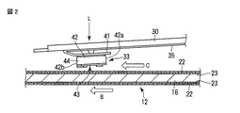
図1は、HDDのトップカバーを取り外して内部構造を示し、図2は、浮上状態の磁気ヘッドおよび磁気ディスクを示している。図1に示すように、HDDは筐体10を備えている。この筐体10は、上面の開口した矩形箱状のベース11と、図示しない矩形板状のトップカバーとを備えている。トップカバーは、複数のねじによりベースにねじ止めされ、ベースの上端開口を閉塞している。これにより、筐体10内部は気密に保持され、呼吸フィルター26を通してのみ、外部と通気可能となっている。ベース11およびトップカバーは例えばアルミ、鉄、ステンレス、冷間圧延炭素鋼鈑等の金属材料によって形成されている。 FIG. 1 shows the internal structure with the top cover of the HDD removed, and FIG. 2 shows the magnetic head and magnetic disk in a floating state. As shown in FIG. 1, the HDD includes a
ベース11上には、磁気記録媒体としての磁気ディスク12および機構部が設けられている。機構部は、磁気ディスク12を支持および回転させるスピンドルモータ13、磁気ディスク12に対して情報の記録、再生を行なう複数、例えば、2つの磁気ヘッド33、これらの磁気ヘッド33を磁気ディスク12の表面に対して移動自在に支持したヘッドアクチュエータ14、ヘッドアクチュエータを回動および位置決めするボイスコイルモータ(以下VCMと称する)15を備えている。また、ベース11上には、磁気ヘッド33が磁気ディスク12の最外周に移動した際、磁気ヘッド33を磁気ディスク12から離間した位置に保持するランプロード機構18、HDDに衝撃等が作用した際、ヘッドアクチュエータ14を退避位置に保持するイナーシャラッチ機構20、およびプリアンプ、ヘッドIC等の電子部品が実装された基板ユニット17が設けられている。 On the
ベース11の外面には、基板ユニット17を介してスピンドルモータ13、VCM15、および磁気ヘッド33の動作を制御する図示しない制御回路基板がねじ止めされ、ベース11の底壁と対向して位置している。 A control circuit board (not shown) that controls the operations of the
図4は、磁気ヘッド33の記録ヘッドおよび磁気ディスク12を拡大して示している。図1、図2、図4に示すように、磁気ディスク12は、ディスクリートトラック型の磁気記録媒体として構成されている。磁気ディスク12は、例えば、直径約2.5インチの円板状に形成され非磁性体からなる基板16を有している。基板16の各表面には、ディスク面に対して垂直方向に容易軸を有する垂直磁気記録の磁性膜23が形成され、この磁性膜により、同芯状の記録トラックを形成する多数のランド部23aが所定の間隔を置いて形成されている。隣合うランド部間には、同芯状の非記録トラックを形成する多数のグルーブ部23bが形成されている。各グルーブ部23bには非磁性材が充填され、あるいは、空隙部として維持されている。ランド部およびグルーブ部に重ねて保護膜22が形成されている。なお、磁気ディスク12は、磁性膜23に下部に軟磁性裏打ち層を有していない。 FIG. 4 shows an enlarged view of the recording head of the
図1に示すように、磁気ディスク12は、スピンドルモータ13のハブに互いに同軸的に嵌合されているとともに、ハブの上端にねじ止めされたクランプばね21によりクランプされ、ハブに固定されている。磁気ディスク12は、駆動モータとしてのスピンドルモータ13により所定の速度で矢印B方向に回転駆動される。 As shown in FIG. 1, the
ヘッドアクチュエータ14は、ベース11の底壁上に固定された軸受部24と、軸受部から延出した複数のアーム27と、を備えている。これらのアーム27は、磁気ディスク12の表面と平行に、かつ、互いに所定の間隔を置いて位置しているとともに、軸受部24から同一の方向へ延出している。ヘッドアクチュエータ14は、弾性変形可能な細長い板状のサスペンション30を備えている。サスペンション30は、その基端がスポット溶接あるいは接着によりアーム27の先端に固定され、アームから延出している。各サスペンション30は対応するアーム27と一体に形成されていてもよい。各サスペンション30の延出端に磁気ヘッド33が支持されている。アーム27およびサスペンション30によりヘッドサスペンションを構成し、このヘッドサスペンションと磁気ヘッド33とによりヘッドサスペンションアッセンブリを構成している。 The
図2に示すように、各磁気ヘッド33は、ほぼ直方体形状のスライダ42とこのスライダの流出端(トレーリング端)に設けられた記録再生用のヘッド部44とを有している。磁気ヘッド33は、サスペンション30の先端部に設けられたジンバルばね41に固定されている。各磁気ヘッド33は、サスペンション30の弾性により、磁気ディスク12の表面に向かうヘッド荷重Lが印加されている。2本のアーム27は所定の間隔を置いて互いに平行に位置し、これらのアームに取り付けられたサスペンション30および磁気ヘッド33は、磁気ディスク12を間に挟んで互いに向かい合っている。 As shown in FIG. 2, each
各磁気ヘッド33は、サスペンション30およびアーム27上に固定された中継フレキシブルプリント回路基板(以下、中継FPCと称する)35を介して後述するメインFPC38に電気的に接続されている。 Each
図1に示すように、基板ユニット17は、フレキシブルプリント回路基板により形成されたFPC本体36と、このFPC本体から延出したメインFPC38とを有している。FPC本体36は、ベース11の底面上に固定されている。FPC本体36上には、プリアンプ37、ヘッドICを含む電子部品が実装されている。メインFPC38の延出端は、ヘッドアクチュエータ14に接続され、各中継FPC35を介して磁気ヘッド33に接続されている。 As shown in FIG. 1, the
VCM15は、軸受部24からアーム27と反対方向に延出した図示しない支持フレーム、および支持フレームに支持されたボイスコイルを有している。ヘッドアクチュエータ14をベース11に組み込んだ状態において、ボイスコイルは、ベース11上に固定された一対のヨーク34間に位置し、これらのヨークおよびヨークに固定された磁石とともにVCM15を構成している。 The
磁気ディスク12が回転した状態でVCM15のボイスコイルに通電することにより、ヘッドアクチュエータ14が回動し、磁気ヘッド33は磁気ディスク12の所望のトラック上に移動および位置決めされる。この際、磁気ヘッド33は、磁気ディスク12の径方向に沿って、磁気ディスクの内周縁部と外周縁部との間を移動される。 By energizing the voice coil of the
次に、磁気ヘッド33の構成について詳細に説明する。図3は、磁気ヘッド33のヘッド部44を拡大して示す断面図、図4は、ヘッド部の記録ヘッドを模式的に示す斜視図、図5は、記録ヘッド部分の主磁極先端部およびサイドシールド部分を拡大して示す側面図、図6は、記録ヘッドをディスク対向面側から見た平面図である。 Next, the configuration of the
図2および図3に示すように、磁気ヘッド33は浮上型のヘッドとして構成され、ほぼ直方体状に形成されたスライダ42と、スライダの流出端(トレーリング)側の端部に形成されたヘッド部44とを有している。スライダ42は、例えば、アルミナとチタンカーバイドの焼結体(アルチック)で形成され、ヘッド部44は薄膜を積層して形成されている。 As shown in FIGS. 2 and 3, the
スライダ42は、磁気ディスク12の表面に対向する矩形状のディスク対向面(空気支持面(ABS))43を有している。スライダ42は、磁気ディスク12の回転によってディスク表面とディスク対向面43との間に生じる空気流Cにより浮上する。空気流Cの方向は、磁気ディスク12の回転方向Bと一致している。スライダ42は、磁気ディスク12表面に対し、ディスク対向面43の長手方向が空気流Cの方向とほぼ一致するように配置されている。 The
スライダ42は、空気流Cの流入側に位置するリーディング端42aおよび空気流Cの流出側に位置するトレーリング端42bを有している。スライダ42のディスク対向面43には、リーディングステップ、トレーリングステップ、サイドステップ、負圧キャビティ等が形成されている。 The
図3に示すように、ヘッド部44は、スライダ42のトレーリング端部42bに薄膜プロセスで形成された再生ヘッド54および記録ヘッド56を有し、記録用ヘッドと再生用ヘッドが分離した分離型磁気ヘッドとして形成されている。 As shown in FIG. 3, the
再生ヘッド54は、磁気抵抗効果を示す磁性膜63と、この磁性膜のトレーリング側およびリーディング側に磁性膜63を挟むように配置された軟磁気特性を有するシールド膜62a、62bと、で構成されている。これら磁性膜63、シールド膜62a、62bの下端は、スライダ42のディスク対向面43に露出している。再生ヘッド54は、磁気ディスク12に記録された情報を再生する。 The reproducing
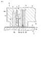
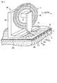
記録ヘッド56は、再生ヘッド54に対して、スライダ42のトレーリング端42b側に設けられている。記録ヘッド56は、トレーリング端側にライトシールド磁極をもつ単磁極ヘッドとして構成されている。図3および図4に示すように、記録ヘッド56は、磁気ディスク12の表面に対して垂直方向の記録磁界を発生させる高透磁率・高飽和磁束密度を有する軟磁性材料からなる主磁極66と、主磁極66のトレーリング側に配置され、主磁極直下の磁性膜23を介して効率的に磁路を閉じるために設けられた軟磁性材料からなるライトシールド磁極(リターン磁極)68と、主磁極66の上部をライトシールド磁極68に連結する連結部67と、磁気ディスク12に信号を書き込む際、主磁極66に磁束を流すために主磁極66およびライトシールド磁極68を含む磁路に巻きつくように配置された記録コイル71と、を有している。 The
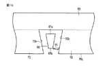
図3ないし図5に示すように、主磁極66は、磁気ディスク12の表面に対して垂直な方向に延び、主磁極66の磁気ディスク側の下端部は、磁気ディスク12に向かって幅が狭くなるように先細に絞り込まれ、その先端部66aは、他の部分に対して幅の狭い柱状に形成されている。図6に示すように、主磁極66の先端部66aは、例えば、断面が台形状に形成され、トレーリング端側に位置した所定幅のトレーリング側端面67a、トレーリング端面と対向しているとともにトレーリング側端面よりも幅の狭いリーディング側端面67b、および両側面を有している。主磁極66の下端面は、スライダ42のディスク対向面43に露出している。トレーリング側端面67aの幅は、磁気ディスク12におけるトラックの幅にほぼ対応している。 As shown in FIGS. 3 to 5, the main
図3および図4に示すように、ライトシールド磁極68は、ほぼL字形状に形成され、その下端部68aは、細長い矩形状に形成されている。ライトシールド磁極68の下端面は、スライダ42のディスク対向面43に露出している。下端部68aのリーディング側端面68bは、磁気ディスク12のトラックの幅方向に沿って延びている。このリーディング側端面68bは、主磁極66のトレーリング側端面67aとライトギャップWGを置いて平行に対向している。 As shown in FIGS. 3 and 4, the write shield
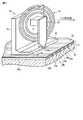
図4ないし図6に示すように、記録ヘッド56は、主磁極66のライトギャップWGの長さ方向両側に、すなわち、主磁極66のトラック幅方向の両側に設けられた一対のサイドシールド70を備えている。これらのサイドシールド70は、ディスク対向面43上では、主磁極66に対して磁気的に分断して設けられる。各サイドシールド70は、高透磁率・高飽和磁束密度を有する軟磁性材料によりライトシールド磁極68の下端部68aと一体に形成され、下端部68aのリーディング側端面68bからスライダ42のリーディング端側に向かって延出している。 4 to 6, the
サイドシールド70の各々は、ディスク対向面43に露出し磁気ディスク12と対向する底面70aと、この底面から立ち上がり主磁極66の側面と隙間を置いて対向する側面70bと、底面70aから立ち上がったリーディング側端面70cと、底面と対向する上面とを有している。本実施形態において、リーディング側端面70cと主磁極66のリーディング側端面67bはほぼ同一平面に並んでいる。各サイドシールド70の高さ(厚さ)SHは、主磁極66の先端部66aの高さよりも大きく形成されている。各サイドシールド70の側面70bは円弧状あるいは傾斜して形成され、主磁極66の先端部66aの側面、および、主磁極66の絞り部66bの側面と隙間を置いて対向している。 Each of the side shields 70 is exposed to the
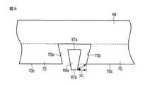
主磁極66の先端部66aの大きさ、および主磁極とサイドシールド70の側面70bとの間隔は、以下のように形成されている。図7(b)に示すように、主磁極66の側面に対向するサイドシールド70の側面70bにおいて、ディスク対向面における主磁極のリーディング側端面67bと最短距離のトラック幅方向の射影成分に位置する部分は、主磁極66が磁気ディスク12における1つの記録トラックのランド部23aと対向する際、このランド部の隣のグルーブ部23bと対向して位置するように配置されている。 The size of the
すなわち、主磁極66のリーディング側端面67bにおけるトラック幅方向の長さPwと、ディスク対向面における主磁極側面のリーディング側端と主磁極側面に対向するサイドシールド70の側面70bとの最短距離のトラック幅方向の射影成分SGと、磁気ディスク12における記録トラックのランド部23aのトラック幅Lwと、非記録トラックのグルーブ部23bの幅Gwとは、以下の式(1)の関係を満たして形成されている。
Lw/2 < Pw/2 + SG < Lw/2 + Gw …(1)
図3に示すように、上記のように形成された再生ヘッド54および記録ヘッド56は、スライダ42のディスク対向面43に露出する部分を除いて、保護絶縁膜72により覆われている。保護絶縁膜72は、ヘッド部44の外形を構成している。That is, the track of the shortest distance between the length Pw in the track width direction of the
Lw / 2 <Pw / 2 + SG <Lw / 2 + Gw (1)
As shown in FIG. 3, the reproducing
以上のように構成されたHDDによれば、VCM15を駆動することにより、ヘッドアクチュエータ14が回動し、磁気ヘッド33は、磁気ディスク12の所望のトラック上に移動され、位置決めされる。また、磁気ヘッド33は、磁気ディスク12の回転によってディスク表面とディスク対向面43との間に生じる空気流Cにより浮上する。HDDの動作時、スライダ42のディスク対向面43はディスク表面に対し隙間を保って対向している。図2に示すように、磁気ヘッド33は、ヘッド部44の記録ヘッド56部分が最も磁気ディスク12表面に接近した傾斜姿勢をとって浮上する。この状態で、磁気ディスク12に対して、再生ヘッド54により記録情報の読み出しを行うとともに、記録ヘッド56により情報の書き込みを行う。 According to the HDD configured as described above, by driving the
情報の書き込みにおいては、記録コイル71により主磁極66を励磁し、この主磁極から直下の磁気ディスク12の記録トラックに垂直方向の記録磁界を印加することにより、所望のトラック幅にて情報を記録する。この際、主磁極66の先端部66aの両側にサイドシールド70を設けることにより、隣接トラックへの書き込みを防止することができる。また、主磁極66の側面に対向するサイドシールド70の側面70bにおいて、ディスク対向面における主磁極のリーディング側端面67bと最短距離に位置する部分は、主磁極66が磁気ディスク12における1つの記録トラックのランド部23aと対向する際、このランド部の隣のグルーブ部23bと対向して位置するように配置されている。すなわち、主磁極66およびサイドシールド70を前述した式(1)の関係を満たすように形成することにより、サイドシールド70の側面70bは、非磁性トラック上に位置するため、主磁極66からサイドシールド70への戻り磁界が生じた場合でも、隣接記録トラック上の既記録情報を消去または劣化を抑制することができる。これにより、オントラックの信号品質を維持したまま、隣接ランドの情報消去を抑制でき、磁気ディスクの磁気記録の高密度化を図ることができる。 In writing information, the main
本実施形態に係る磁気ヘッドと、比較例に係る磁気ヘッドと、を用意し、これらの性能を比較した。図7(b)に破線で示すように、比較例の磁気ヘッドは、従来の構造を有し、サイドシールド70の側面が、主磁極が対向する記録対象となる記録トラック23aに隣接する記録トラックの直上に位置している。 A magnetic head according to this embodiment and a magnetic head according to a comparative example were prepared, and their performance was compared. As shown by a broken line in FIG. 7B, the magnetic head of the comparative example has a conventional structure, and the side surface of the
本実施形態に係る磁気ヘッドにおいて、主磁極66は、飽和磁束密度Bs=2.4Tの材料で形成し、サイドシールド70は飽和磁束密度Bs=1.9Tの材料で形成したものを用いた。比較例に係る磁気ヘッドとして、以下の式(2)を満たす磁気ヘッドを用いている。
Pw/2 + SG > Lw/2 + Gw …(2)
本実施形態では、Pw=30nm、SG=40nm、Lw=100nm、Gw=50nmとし、比較例では、Pw=30nm、SG=110nm、Lw=100nm、Gw=50nmとした。In the magnetic head according to the present embodiment, the main
Pw / 2 + SG> Lw / 2 + Gw (2)
In this embodiment, Pw = 30 nm, SG = 40 nm, Lw = 100 nm, and Gw = 50 nm. In the comparative example, Pw = 30 nm, SG = 110 nm, Lw = 100 nm, and Gw = 50 nm.
図7(a)は、本実施形態に係る磁気ヘッドと、比較例に係る磁気ヘッドとについて、記録磁界分布の片側オフトラック方向プロファイルを比較して示している。トラック幅方向位置=0の位置を記録ヘッドの主磁極66のトラック幅方向中心位置とし、本実施形態に係る磁気ヘッドのプロファイルを■で示される線で示し、比較例に係る磁気ヘッドのプロファイルを実線で示している。 FIG. 7A shows a comparison of the one-side off-track direction profiles of the recording magnetic field distribution for the magnetic head according to the present embodiment and the magnetic head according to the comparative example. The position of the track width direction position = 0 is the center position in the track width direction of the main
比較例では、主磁極66からの磁束がサイドシールド70へ集中し、ディスク対向面において主磁極のリーディング部側面と対向するサイドシールド側面部分で戻り磁界が増大している。一方図、本実施形態に係る磁気ヘッドでは、比較例に比べて、主磁極66直下での磁界強度を維持し、主磁極から発生した磁束によって生じる戻り磁界の増大を隣接グルーブ23b内で閉じることができる。 In the comparative example, the magnetic flux from the main
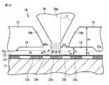
図8(a)は、本実施形態に係る磁気ヘッドおよび上記比較例に係る磁気ヘッドにおけるビットエラーレート(BER)のオフトラック方向プロファイルを比較して示している。図8(b)は、本実施形態および比較例に係る記録ヘッドのディスク対向面における構造を示している。トラック幅方向位置=0の位置を記録ヘッドの主磁極66のトラック幅方向中心位置とする。 FIG. 8A shows a comparison of off-track direction profiles of the bit error rate (BER) in the magnetic head according to the present embodiment and the magnetic head according to the comparative example. FIG. 8B shows the structure on the disk facing surface of the recording head according to the present embodiment and the comparative example. The position where the track width direction position = 0 is the center position of the main
図8(a)において、□の特性線は、比較例の磁気ヘッドによって、トラック幅方向位置=0を中心としてトラック幅方向に左右にオフセットしながら、磁気ディスクにランダムデータを書き込み再生を行った場合のビットエラーレートを示している。○の特性線は、比較例の磁気ヘッドにより、トラック幅方向位置=0の位置で10000回書き込みを行った後、再びトラック幅方向に左右にオフセットさせながら再生した場合のビットエラーレートのオフトラック方向プロファイルを示している。主磁極66からの磁束がサイドシールド70へ戻る磁束が集中した場合、ディスク対向面における主磁極のリーディング部側面と対向するサイドシールド側面部分で戻り磁界が増大し、このサイドシールド側面部分の直下で情報消去が起こる。そのため、□の特性線に比べ、トラック幅方向両側のサイドシールドの側面部分の位置、すなわち隣接ランド部でのビットエラーレートが劣化していることが分かる。 In FIG. 8 (a), the characteristic line marked with □ was written and reproduced with random data on the magnetic disk while being offset left and right in the track width direction around the track width direction position = 0 with the magnetic head of the comparative example. Shows the bit error rate. ○ Characteristic line indicates off-track of bit error rate when writing with 10000 times at the track width direction position = 0 with the magnetic head of the comparative example and then playing back while offsetting left and right again in the track width direction A direction profile is shown. When the magnetic flux from the main
図8(a)において、●の特性線は、本実施形態の磁気ヘッドによって、トラック幅方向位置=0を中心としてトラック幅方向に左右にオフセットしながら、磁気ディスクにランダムデータを書き込み再生を行った場合のビットエラーレートを示している。■の特性線は、本実施形態の磁気ヘッドにより、トラック幅方向位置=0の位置で10000回書き込みを行った後、再びトラック幅方向に左右にオフセットさせながら再生した場合のビットエラーレートのオフトラック方向プロファイルを示している。これらのプロファイルから、本実施形態の記録ヘッドで記録を行う場合、主磁極66から発生した磁束を隣接グルーブ23b内で閉じることができるため、隣接ランド部23aの信号品質を劣化させることがなく、高いトラック密度化が可能となる。 In FIG. 8A, the characteristic line marked with ● indicates that the magnetic head of this embodiment performs random data writing / reproducing on the magnetic disk while being offset left and right in the track width direction around the track width direction position = 0. The bit error rate in the case of The characteristic line (2) indicates that the bit error rate is off when the magnetic head of this embodiment performs writing 10,000 times at the track width direction position = 0 and then reproduces the data while offsetting left and right again in the track width direction. A track direction profile is shown. From these profiles, when recording is performed with the recording head of the present embodiment, the magnetic flux generated from the main
上述した第1の実施形態に係る磁気ヘッドは、サイドシールド70のリーディング側端面70cと主磁極66のリーディング側端面67bとが異なる平面に位置する場合にも適用することができる。図9は、ディスク対向面においける主磁極66のリーディング側端面67bが、サイドシールド70のリーディング側端面70cよりもリーディング側にずれている記録ヘッドを示している。この場合の最短距離のトラック幅方向の射影成分SGの定義も、ディスク対向面における主磁極66のリーディング側端と、主磁極の側面と対向するサイドシールド側面との最短距離のトラック幅方向の射影成分とし、前述した式(1)を満たす構成としている。 The magnetic head according to the first embodiment described above can also be applied when the leading
図10は、ディスク対向面においける主磁極66のリーディング側端面67bが、サイドシールド70のリーディング側端面70cよりもトレーリング側にずれている記録ヘッドを示している。この場合の最短距離のトラック幅方向の射影成分SGの定義も、ディスク対向面における主磁極66のリーディング側端と、主磁極の側面と対向するサイドシールド側面との最短距離のトラック幅方向の射影成分とし、前述した式(1)を満たす構成としている。 FIG. 10 shows a recording head in which the
次に、この発明の第2の実施形態に係るHDDの磁気ヘッドについて説明する。図11は、ヘッド部の記録ヘッドを模式的に示す斜視図、図12は、記録ヘッド部分の主磁極先端部およびサイドシールド部分を拡大して示す側面図、図13は、主磁極およびサイドシールドをディスク対向面側から見た記録ヘッドの平面図である。 Next explained is a magnetic head of the HDD according to the second embodiment of the invention. 11 is a perspective view schematically showing the recording head of the head portion, FIG. 12 is an enlarged side view showing the main magnetic pole tip portion and the side shield portion of the recording head portion, and FIG. 13 is the main magnetic pole and side shield. 2 is a plan view of the recording head as viewed from the disk facing surface side.
図11ないし図13に示すように、記録ヘッド56は、主磁極66のライトギャップWGの長さ方向両側に、すなわち、主磁極66のトラック幅方向の両側に設けられた一対のサイドシールド70を備えている。これらのサイドシールド70は、ディスク対向面43上では、主磁極66に対して磁気的に分断して設けられる。各サイドシールド70は、高透磁率・高飽和磁束密度を有する軟磁性材料によりライトシールド磁極68の下端部68aと一体に形成され、下端部68aのリーディング側端面68bからスライダ42のリーディング端側に向かって延出している。 As shown in FIGS. 11 to 13, the
サイドシールド70の各々は、ディスク対向面43に露出し磁気ディスク12と対向する底面70aと、この底面から立ち上がり主磁極66の側面と隙間を置いて対向する側面70bと、底面70aから立ち上がったリーディング側端面70cと、底面と対向する上面とを有している。本実施形態において、リーディング側端面70cと主磁極66のリーディング側端面67bはほぼ同一平面に並んでいる。各サイドシールド70の高さ(厚さ)SHは、主磁極66の先端部66aの高さよりも大きく形成されている。各サイドシールド70の側面70bは円弧状あるいは傾斜して形成され、主磁極66の先端部66aの側面、および、主磁極66の絞り部66bの側面と隙間を置いて対向している。 Each of the side shields 70 is exposed to the
第2の実施形態によれば、各サイドシールド70の底面70aに凹所74が形成され、主磁極66の先端部66aの両側に位置している。凹所74は、サイドシールド70と同一の幅を有し、サイドシールドの底面70aおよび側面70bに開口している。これにより、各サイドシールド70の内、主磁極60の両側に位置する部分は、凹所74の分だけ磁気ディスク12から離間し、凹所74の底とディスク表面との間隔SDは、サイドシールドの底面70aとディスク表面との間隔Rよりも大きくなっている。 According to the second embodiment, the
また、記録ヘッド56は、スライダのディスク対向面における主磁極66のリーディング側端面と主磁極側面と対向するサイドシールド側面との最短距離のトラック幅方向の射影成分SGと、凹所74が形成された位置における主磁極66のリーディング部側面と対向するサイドシールド側面との最短距離のトラック幅方向の射影成分SG2とがSG>SG2の関係を満たしている。更に、記録ヘッド56は、主磁極66とサイドシールド側面70bとの最短距離のトラック幅方向の射影成分SG2が、サイドシールド側面70bと磁気ディスク表面との間隔SDに対して、以下の式(3)の関係を満たし、かつ、最短距離のトラック幅方向の射影成分SG2が主磁極66のリーディング側端面67bにおけるトラック幅方向の長さPwと磁気ディスク12のランド部23aの幅Lwと非記録領域のグルーブ部23bの幅Gwとについて前述した式(1)と同様の式(4)を満たすように形成されている。
SG2 > SD …(3)
Lw/2 < Pw/2 + SG2 < Lw/2 + Gw …(4)
なお、磁気ヘッドおよびHDDの他の構成は、前述した第1の実施形態と同一であり、同一の部分には同一の参照符号を付してその詳細な説明を省略する。The
SG2> SD (3)
Lw / 2 <Pw / 2 + SG2 <Lw / 2 + Gw (4)
The other configurations of the magnetic head and the HDD are the same as those of the first embodiment described above, and the same reference numerals are given to the same portions, and detailed description thereof is omitted.
上記のように構成された磁気ヘッドによれば、主磁極66の側面に対向するサイドシールド70の側面70bにおいて、ディスク対向面における主磁極のリーディング側端面67bと最短距離のトラック幅方向の射影成分に位置する部分は、主磁極66が磁気ディスク12における1つの記録トラックのランド部23aと対向する際、このランド部の隣のグルーブ部23bと対向して位置するように配置されている。すなわち、主磁極66およびサイドシールド70を前述した式(4)の関係を満たすように形成することにより、サイドシールド70の側面70bは、非磁性トラック上に位置するため、主磁極66からサイドシールド70への戻り磁界が生じた場合でも、隣接記録トラック上の既記録情報を消去または劣化を抑制することができる。これにより、オントラックの信号品質を維持したまま、隣接ランドの情報消去を抑制でき、磁気ディスクの磁気記録の高密度化を図ることができる。更に、サイドシールド70に凹所74を形成し、サイドシールド側面70bとディスク表面との間隔SDを広くすることにより、主磁極66からサイドシールド70への戻り磁界を低減し、隣接記録トラック上の既記録情報を消去または劣化を一層抑制することが可能となる。 According to the magnetic head configured as described above, on the
本実施形態に係る磁気ヘッドと、比較例2に係る磁気ヘッドと、を用意し、これらの性能を比較した。比較例2に係る磁気ヘッドは、以下の式(5)、(6)を満たす構成を有しているものとする。
Pw/2 + SG > Lw/2 + Gw …(5)
SG < SG2 …(6)
本実施形態に係る磁気ヘッドにおいて、主磁極66は、飽和磁束密度Bs=2.4Tの材料で形成し、サイドシールド70は飽和磁束密度Bs=1.9Tの材料で形成したものを用いた。本実施形態では、Pw=30nm、SG=60nm、SG2=40nm、Lw=100nm、Gw=50nmとし、比較例2では、Pw=30nm、SG=110nm、SG2=200nm、Lw=100nm、Gw=50nmとした。また、磁気ディスクは、ディスクリートトラック型の磁気記録媒体であって、記録層の下部に軟磁気特性を有する下地層を有していない磁気ディスクを用いた。The magnetic head according to the present embodiment and the magnetic head according to Comparative Example 2 were prepared, and their performance was compared. The magnetic head according to Comparative Example 2 is assumed to have a configuration that satisfies the following expressions (5) and (6).
Pw / 2 + SG> Lw / 2 + Gw (5)
SG <SG2 (6)
In the magnetic head according to the present embodiment, the main
比較の結果、本実施形態に係る磁気ヘッドは、比較例2に比べて、主磁極66直下での磁界強度を維持または向上させ、隣接ランド部への戻り磁界を減少させることができる。また、トラック幅方向位置=0の位置から、トラック方向に左右にオフセットしながら、磁気ディスクにランダムデータを書き込み再生を行いビットエラーレートのオフトラックプロファイルを測定した後、トラック幅方向位置=0の位置で10000回書き込み、オフトラックさせながら再生を行った場合のビットエラーレートのオフトラック方向プロファイルを測定し、その変化を調べた。従来例2の記録ヘッドの場合、サイドシールドエッジ近傍直下の隣接トラックでビットエラーレートが劣化しているのに対して、本実施形態の記録ヘッドでは、主磁極から発生した磁束を隣接グルーブ部内で閉じることができるため、隣接トラックでビットエラーレートは劣化しなかった。このように、本実施形態に係る記録ヘッドを用いることによって、隣接トラックの信号品質を劣化させることなく、高いトラック密度化を可能とする効果が得られることが分かる。
その他、第2の実施形態に係る磁気ヘッドにおいても、第1の実施形態と同様の作用効果を得ることができる。As a result of the comparison, the magnetic head according to the present embodiment can maintain or improve the magnetic field strength directly below the main
In addition, in the magnetic head according to the second embodiment, the same function and effect as those of the first embodiment can be obtained.
本発明は上記実施形態そのままに限定されるものではなく、実施段階ではその要旨を逸脱しない範囲で構成要素を変形して具体化できる。また、上記実施形態に開示されている複数の構成要素の適宜な組み合わせにより、種々の発明を形成できる。例えば、実施形態に示される全構成要素から幾つかの構成要素を削除してもよい。さらに、異なる実施形態にわたる構成要素を適宜組み合わせてもよい。 The present invention is not limited to the above-described embodiments as they are, and can be embodied by modifying the constituent elements without departing from the scope of the invention in the implementation stage. In addition, various inventions can be formed by appropriately combining a plurality of constituent elements disclosed in the embodiment. For example, some components may be deleted from all the components shown in the embodiment. Furthermore, constituent elements over different embodiments may be appropriately combined.
例えば、記録ヘッドを構成する各要素の材料、形状、大きさ等は、必要に応じて変更可能である。また、磁気ディスク装置において、磁気ディスクおよび磁気ヘッドの数は、必要に応じて増加可能であり、磁気ディスクのサイズも種々選択可能である。 For example, the material, shape, size, and the like of each element constituting the recording head can be changed as necessary. Further, in the magnetic disk device, the number of magnetic disks and magnetic heads can be increased as necessary, and various sizes of magnetic disks can be selected.
10…筺体、11…ベース、12…磁気ディスク、13…スピンドルモータ、
14…ヘッドアクチュエータ、25…制御回路基板、27…アーム、
30…サスペンション、33…磁気ヘッド、42…スライダ、43…ディスク対向面、
44…ヘッド部、54…再生ヘッド、56…記録ヘッド、66…主磁極、
66b…絞り部、67a…トレーリング側端面、67b…リーディング側端面、
68…ライトシールド磁極、70…サイドシールド、70a…底面、70b…側面、
71…記録コイル、74…凹所、WG…ライトギャップ、
SG…最短距離のトラック幅方向の射影成分、
SG2…最短距離のトラック幅方向の射影成分、DESCRIPTION OF
14 ... head actuator, 25 ... control circuit board, 27 ... arm,
30 ... Suspension, 33 ... Magnetic head, 42 ... Slider, 43 ... Disc facing surface,
44 ... head portion, 54 ... reproducing head, 56 ... recording head, 66 ... main magnetic pole,
66b ... throttle part, 67a ... trailing side end face, 67b ... leading side end face,
68 ... Write shield magnetic pole, 70 ... Side shield, 70a ... Bottom, 70b ... Side,
71 ... Recording coil, 74 ... Recess, WG ... Write gap,
SG: Projection component in the track width direction of the shortest distance,
SG2 ... Projection component in the track width direction of the shortest distance,
Claims (10)
Translated fromJapanese前記磁気記録媒体の表面と対向する対向面を有するスライダと、
前記スライダに設けられ前記記録媒体に対し情報処理を行うヘッド部と、を備え、
前記ヘッド部は、前記磁性膜に対し垂直な記録磁界を印加する主磁極と、前記主磁極のトレーリング側にライトギャップを置いて対向するライトシールド磁極と、前記主磁極のトラック幅方向の両側に、前記主磁極から磁気的に離間して設けられたサイドシールドと、を有し、
前記主磁極のリーディング側端におけるトラック方向の長さPwと、前記対向面における前記主磁極側面のリーディング端と主磁極側面に対向するサイドシールド側面との最短距離のトラック幅方向の射影成分SGと、前記磁気記録媒体における記録トラックのランド部のトラック幅Lwと、非記録トラックのグルーブ部の幅Gwとは、
Lw/2 < Pw/2 + SG < Lw/2 + Gw
の関係に形成されている磁気ヘッド。Discrete comprising a plurality of land portions for forming a recording track having a magnetic film having an easy axis in a direction perpendicular to the medium surface, and a groove portion provided between adjacent land portions for forming a non-recording track A magnetic head for perpendicular recording for recording on a track type magnetic recording medium,
A slider having a facing surface facing the surface of the magnetic recording medium;
A head unit provided on the slider and performing information processing on the recording medium,
The head portion includes a main magnetic pole that applies a recording magnetic field perpendicular to the magnetic film, a write shield magnetic pole that faces the trailing side of the main magnetic pole with a write gap, and both sides of the main magnetic pole in the track width direction. And a side shield provided magnetically spaced from the main pole,
The length Pw in the track direction at the leading end of the main magnetic pole, and the projection component SG in the track width direction of the shortest distance between the leading end of the main magnetic pole side surface and the side shield side surface facing the main magnetic pole side surface on the facing surface; The track width Lw of the land portion of the recording track and the width Gw of the groove portion of the non-recording track in the magnetic recording medium are:
Lw / 2 <Pw / 2 + SG <Lw / 2 + Gw
Magnetic head formed in the relationship.
前記磁気記録媒体の表面と対向する対向面を有するスライダと、
前記スライダに設けられ前記記録媒体に対し情報処理を行うヘッド部と、を備え、
前記ヘッド部は、前記磁性膜に対し垂直な記録磁界を印加する主磁極と、前記主磁極のトレーリング側にライトギャップを置いて対向するライトシールド磁極と、前記主磁極のトラック幅方向の両側に、前記主磁極から磁気的に離間して設けられたサイドシールドと、を有し、
前記主磁極側面に対向するサイドシールド側面において、前記対向面における前記主磁極側面のリーディング側端と最短距離のトラック幅方向の射影成分に位置する部分は、前記主磁極が前記磁気記録媒体における1つの記録トラックのランド部と対向する際、このランド部の隣のグルーブ部と対向して位置するように配置されている磁気ヘッド。Discrete comprising a plurality of land portions for forming a recording track having a magnetic film having an easy axis in a direction perpendicular to the medium surface, and a groove portion provided between adjacent land portions for forming a non-recording track A magnetic head for perpendicular recording for recording on a track type magnetic recording medium,
A slider having a facing surface facing the surface of the magnetic recording medium;
A head unit provided on the slider and performing information processing on the recording medium,
The head portion includes a main magnetic pole that applies a recording magnetic field perpendicular to the magnetic film, a write shield magnetic pole that faces the trailing side of the main magnetic pole with a write gap, and both sides of the main magnetic pole in the track width direction. And a side shield provided magnetically spaced from the main pole,
In the side shield side surface facing the main magnetic pole side surface, the portion of the opposing surface located in the projection component in the track width direction of the shortest distance from the leading side end of the main magnetic pole side surface is 1 in the magnetic recording medium. A magnetic head disposed so as to face a groove portion adjacent to the land portion when facing the land portion of one recording track.
SG>SG2であり、前記ヘッド部は、
Lw/2 < Pw/2 + SG2 < Lw/2 + Gw
の関係に形成されている請求項4に記載の磁気ヘッド。Projection component SG in the track width direction of the shortest distance between the leading end face of the main pole on the disk facing surface of the slider and the side shield side face facing the main pole side face, and the leading of the main pole at the position where the recess is formed. Projection component G2 in the track width direction of the shortest distance between the side surface and the side shield side surface facing
SG> SG2, and the head portion is
Lw / 2 <Pw / 2 + SG2 <Lw / 2 + Gw
The magnetic head according to claim 4, wherein the magnetic head is formed in the relationship of
前記磁気記録媒体を支持しているとともに回転する駆動部と、
前記磁気記録媒体の表面と対向する対向面を有するスライダ、および前記スライダに設けられ前記磁気記録媒体に対し情報処理を行うヘッド部を有する磁気ヘッドと、を備え、
前記ヘッド部は、前記磁性膜に対し垂直な記録磁界を印加する主磁極と、前記主磁極のトレーリング側にライトギャップを置いて対向するライトシールド磁極と、前記主磁極のトラック幅方向の両側に、前記主磁極から磁気的に離間して設けられたサイドシールドと、を有し、
前記主磁極のリーディング側端におけるトラック方向の長さPwと、前記対向面における前記主磁極側面のリーディング端と主磁極側面に対向するサイドシールド側面との最短距離のトラック幅方向の射影成分SGと、前記磁気記録媒体における記録トラックのランド部のトラック幅Lwと、非記録トラックのグルーブ部の幅Gwとは、
Lw/2 < Pw/2 + SG < Lw/2 + Gw
の関係に形成されている磁気ディスク装置。Discrete comprising a plurality of land portions for forming a recording track having a magnetic film having an easy axis in a direction perpendicular to the medium surface, and a groove portion provided between adjacent land portions for forming a non-recording track A track-type magnetic recording medium;
A drive unit that supports and rotates the magnetic recording medium;
A slider having a facing surface facing the surface of the magnetic recording medium, and a magnetic head provided on the slider and having a head portion that performs information processing on the magnetic recording medium,
The head portion includes a main magnetic pole that applies a recording magnetic field perpendicular to the magnetic film, a write shield magnetic pole that faces the trailing side of the main magnetic pole with a write gap, and both sides of the main magnetic pole in the track width direction. And a side shield provided magnetically spaced from the main pole,
The length Pw in the track direction at the leading end of the main magnetic pole, and the projection component SG in the track width direction of the shortest distance between the leading end of the main magnetic pole side surface and the side shield side surface facing the main magnetic pole side surface on the facing surface; The track width Lw of the land portion of the recording track and the width Gw of the groove portion of the non-recording track in the magnetic recording medium are:
Lw / 2 <Pw / 2 + SG <Lw / 2 + Gw
The magnetic disk device formed in the relationship.
SG>SG2であり、前記ヘッド部は、
Lw/2 < Pw/2 + SG2 < Lw/2 + Gw
の関係に形成されている請求項8に記載の磁気ディスク装置。Projection component SG in the track width direction of the shortest distance between the leading end face of the main pole on the disk facing surface of the slider and the side shield side face facing the main pole side face, and the leading of the main pole at the position where the recess is formed. Projection component SG2 in the track width direction of the shortest distance between the side surface and the side shield side surface facing
SG> SG2, and the head portion is
Lw / 2 <Pw / 2 + SG2 <Lw / 2 + Gw
The magnetic disk device according to claim 8, wherein the magnetic disk device is formed in the relationship of
Priority Applications (1)
| Application Number | Priority Date | Filing Date | Title |
|---|---|---|---|
| JP2009225031AJP2011076651A (en) | 2009-09-29 | 2009-09-29 | Magnetic head and disk device equipped with the same |
Applications Claiming Priority (1)
| Application Number | Priority Date | Filing Date | Title |
|---|---|---|---|
| JP2009225031AJP2011076651A (en) | 2009-09-29 | 2009-09-29 | Magnetic head and disk device equipped with the same |
Publications (1)
| Publication Number | Publication Date |
|---|---|
| JP2011076651Atrue JP2011076651A (en) | 2011-04-14 |
Family
ID=44020494
Family Applications (1)
| Application Number | Title | Priority Date | Filing Date |
|---|---|---|---|
| JP2009225031APendingJP2011076651A (en) | 2009-09-29 | 2009-09-29 | Magnetic head and disk device equipped with the same |
Country Status (1)
| Country | Link |
|---|---|
| JP (1) | JP2011076651A (en) |
Citations (2)
| Publication number | Priority date | Publication date | Assignee | Title |
|---|---|---|---|---|
| JP2006120272A (en)* | 2004-10-25 | 2006-05-11 | Hitachi Global Storage Technologies Netherlands Bv | Magnetic head for perpendicular recording |
| JP2008171483A (en)* | 2007-01-09 | 2008-07-24 | Hitachi Global Storage Technologies Netherlands Bv | Magnetic disk unit |
- 2009
- 2009-09-29JPJP2009225031Apatent/JP2011076651A/enactivePending
Patent Citations (2)
| Publication number | Priority date | Publication date | Assignee | Title |
|---|---|---|---|---|
| JP2006120272A (en)* | 2004-10-25 | 2006-05-11 | Hitachi Global Storage Technologies Netherlands Bv | Magnetic head for perpendicular recording |
| JP2008171483A (en)* | 2007-01-09 | 2008-07-24 | Hitachi Global Storage Technologies Netherlands Bv | Magnetic disk unit |
Similar Documents
| Publication | Publication Date | Title |
|---|---|---|
| JP4599452B1 (en) | Magnetic head and disk device provided with the same | |
| JP4686630B1 (en) | Magnetic head and disk device provided with the same | |
| JP4693923B2 (en) | Magnetic head and disk device provided with the same | |
| US7944646B2 (en) | Magnetic disk drive | |
| JP2010176732A (en) | Magnetic head and disk apparatus having the same | |
| JP5784542B2 (en) | Magnetic recording head and disk device provided with the same | |
| US20130163122A1 (en) | Magnetic head having high-frequency oscillatory elements and disk drive with the same | |
| JP5172937B2 (en) | Magnetic head and disk device provided with the same | |
| JP4881458B2 (en) | Magnetic head and disk device provided with the same | |
| JP2014203489A (en) | Recording head and disk device with the same | |
| JP2012150863A (en) | Recording head and disk drive with the same | |
| US9013966B1 (en) | Magnetic recording head and disk device including the same | |
| JP2013143172A (en) | Recording head and disk device having the same | |
| JP2010287288A (en) | Magnetic head and disk device provided with the same | |
| JP5762987B2 (en) | Magnetic head and disk device provided with the same | |
| JP2017117506A (en) | Magnetic recording head and disk device provided with the same | |
| JP5113388B2 (en) | Magnetic disk unit | |
| JP2011076651A (en) | Magnetic head and disk device equipped with the same | |
| JP2018198101A (en) | Magnetic head and disk device including the same | |
| JP2016219070A (en) | Magnetic recording head and disk device provided with the same | |
| US20140362468A1 (en) | Magnetic recording head and disk drive with the same | |
| JP2012104217A (en) | Magnetic head, and disk device having the same |
Legal Events
| Date | Code | Title | Description |
|---|---|---|---|
| A02 | Decision of refusal | Effective date:20110426 Free format text:JAPANESE INTERMEDIATE CODE: A02 |