JP2011070784A - Bulb replacement device - Google Patents
Bulb replacement deviceDownload PDFInfo
- Publication number
- JP2011070784A JP2011070784AJP2009218489AJP2009218489AJP2011070784AJP 2011070784 AJP2011070784 AJP 2011070784AJP 2009218489 AJP2009218489 AJP 2009218489AJP 2009218489 AJP2009218489 AJP 2009218489AJP 2011070784 AJP2011070784 AJP 2011070784A
- Authority
- JP
- Japan
- Prior art keywords
- bulb
- support surface
- light bulb
- flat
- spherical
- Prior art date
- Legal status (The legal status is an assumption and is not a legal conclusion. Google has not performed a legal analysis and makes no representation as to the accuracy of the status listed.)
- Granted
Links
- 239000000853adhesiveSubstances0.000claimsabstractdescription54
- 230000001070adhesive effectEffects0.000claimsabstractdescription54
- 230000007246mechanismEffects0.000claimsdescription42
- 230000002093peripheral effectEffects0.000claimsdescription40
- 238000009751slip formingMethods0.000claimsdescription3
- 230000036544postureEffects0.000description24
- 238000010586diagramMethods0.000description4
- 239000002390adhesive tapeSubstances0.000description3
- 239000010953base metalSubstances0.000description3
- 230000035939shockEffects0.000description3
- 230000005484gravityEffects0.000description2
- 230000012447hatchingEffects0.000description2
- 239000002184metalSubstances0.000description2
- 229910052751metalInorganic materials0.000description2
- 230000002265preventionEffects0.000description2
- 229920003002synthetic resinPolymers0.000description2
- 239000000057synthetic resinSubstances0.000description2
- 229910052782aluminiumInorganic materials0.000description1
- XAGFODPZIPBFFR-UHFFFAOYSA-NaluminiumChemical compound[Al]XAGFODPZIPBFFR-UHFFFAOYSA-N0.000description1
- 238000005452bendingMethods0.000description1
- 230000003028elevating effectEffects0.000description1
- 239000011521glassSubstances0.000description1
- 238000003780insertionMethods0.000description1
- 230000037431insertionEffects0.000description1
- 238000009434installationMethods0.000description1
- 238000004519manufacturing processMethods0.000description1
- 230000011514reflexEffects0.000description1
- 229920005989resinPolymers0.000description1
- 239000011347resinSubstances0.000description1
- 238000000926separation methodMethods0.000description1
- 229910001220stainless steelInorganic materials0.000description1
- 239000010935stainless steelSubstances0.000description1
Images


Landscapes
- Fastening Of Light Sources Or Lamp Holders (AREA)
- Non-Portable Lighting Devices Or Systems Thereof (AREA)
Abstract
Description
Translated fromJapanese本発明は、手の届かない高所に取り付けられた電球を交換するのに使用される電球交換器具に関する。 The present invention relates to a light bulb exchange device used for replacing a light bulb mounted at an unreachable height.
従来、手の届かない高所に取り付けられた電球は、人が椅子や踏み台に載って腕を伸ばして手で直接まわして緩めてソケットから取り外した後、新規のものを同じく手で直接にソケットにねじ込んで取り付けていた。このため、高齢者、体の不自由な人、妊婦等は、椅子や踏み台に載って電球を交換することが危険であった。また、電球の交換に椅子や踏み台を用意しなければならなかった。 Conventionally, light bulbs installed in high places that are out of reach are placed on chairs or step stools, arms are stretched and turned directly by hand, loosened and removed from the socket, then the new one is also socketed directly by hand It was screwed in and attached. For this reason, it has been dangerous for elderly people, people with reduced mobility, pregnant women, etc. to replace the light bulb on a chair or a step. In addition, a chair and a step had to be prepared to replace the light bulb.
そこで、安全で、椅子や踏み台を用意することなく電球の交換ができる電球交換器具が特許文献1に開示されている。 Therefore,
この電球交換器具は、昇降操作棒の先端に設けられた弾性部材からなる電球把持部と、昇降操作棒の外周に同心状にスライド自在に配置された円筒状のスライド棒と、このスライド棒の先端に設けられた漏斗状の押圧部と、昇降操作棒をスライド棒に引き込む方向に付勢するばねとで構成されている。 The light bulb replacement device includes a light bulb gripping portion made of an elastic member provided at the tip of the lifting operation rod, a cylindrical slide rod arranged concentrically on the outer periphery of the lifting operation rod, It is comprised by the funnel-shaped press part provided in the front-end | tip, and the spring which urges | biases the raising / lowering operation stick | rod in the direction pulled in to a slide stick | rod.
通常、電球把持部は、ばねが昇降操作棒をスライド棒に引き込む方向に付勢しているので、押圧部内に引き込まれて窄まされている。電球を交換するとき、昇降操作棒をばねに抗して、スライド棒から押し出すように上昇させると、電球把持部は、押圧部内から出て広がり、電球の略下半分を受け入れることができるようになる。そして、昇降操作棒をばねによって、スライド棒に引き込ませると、電球把持部は、押圧部内に引き込まれて窄まり、ソケットにねじ込まれている電球を把持する。この状態で、昇降操作軸とスライド軸とを一体に回すと電球把持部も一体に回り、電球把持部は電球を把持したまま回転する。この結果、電球をソケットから外すことができる。 Usually, the light bulb gripping portion is urged in the direction in which the spring pulls the elevating operation rod into the slide rod, so that it is drawn into the pressing portion and constricted. When replacing the light bulb, if the lifting operation rod is lifted against the spring and pushed out from the slide rod, the light bulb gripping part will spread out from inside the pressing part so that it can accept the lower half of the light bulb Become. When the lifting / lowering operation rod is pulled into the slide rod by the spring, the light bulb gripping portion is drawn into the pressing portion and narrows, and grips the light bulb screwed into the socket. In this state, when the lifting operation shaft and the slide shaft are rotated together, the light bulb gripping portion also rotates integrally, and the light bulb gripping portion rotates while gripping the light bulb. As a result, the light bulb can be removed from the socket.
しかし、従来の電球交換器具は、電球把持部が電球を横方向から把持して押圧部内に多少引き込まれて窄まり、電球を把持するようになっているので、押圧部の形状と異なる電球を把持するのが困難であった。 However, in the conventional light bulb replacement device, the light bulb gripping part grips the light bulb from the lateral direction and is slightly pulled into the pressing part to narrow the light bulb. It was difficult to grasp.
また、電球把持部が電球を把持する把持力は、電球把持部を押圧部内に引き込むばねによって得ていた。このため、保持力は、強過ぎると電球を割るおそれがあるので、おのずと、交換頻度の多い電球に合わせていた。しかし、その電球より小さい電球の場合、把持力不足が生じて、円滑に電球の交換を行うことができないことがあった。また、逆に、大きい電球の場合、把持力が強くなり、電球を割るおそれがあった。 Further, the gripping force with which the light bulb gripping part grips the light bulb is obtained by a spring that pulls the light bulb gripping part into the pressing part. For this reason, if the holding force is too strong, there is a possibility of breaking the light bulb. However, in the case of a light bulb that is smaller than the light bulb, the gripping force is insufficient, and the light bulb may not be exchanged smoothly. On the other hand, in the case of a large light bulb, the gripping force becomes strong and there is a risk of breaking the light bulb.
また、把持部等が可動であるために構造が複雑となり、さらに、昇降操作棒とスライド棒とが二重構造となるために、重さが重いという問題があった。 Further, since the gripping portion and the like are movable, the structure is complicated, and further, there is a problem that the lifting operation bar and the slide bar have a double structure, so that the weight is heavy.
また、電球の交換中に把持部が緩んだ場合には、電球が大きく姿勢を崩して落下するおそれもあった。 In addition, when the gripping part is loosened during the replacement of the light bulb, the light bulb may be greatly deformed and dropped.
そこで、本発明は、構造が簡単で軽量化が可能でありながら、形状の異なる電球を、交換中に電球の姿勢を崩すことなく安全で確実に交換することができる電球交換器具を提供することを目的とするものである。 Accordingly, the present invention provides a light bulb exchange device that can replace a light bulb having a different shape safely and reliably without changing the posture of the light bulb during replacement, while being simple in structure and capable of being reduced in weight. It is intended.
請求項1に係る発明は、手の届かない高所に露出状態で下向きに取り付けられた電球を交換する際に、立てた状態で使用される棒状の電球交換器具に関する。この発明に係る電球交換器具は、人手により下端側が回転操作される操作棒と、前記操作棒の上端に椀状に設けられ、内周面において球状電球と扁平電球とを択一的に保持する電球保持体と、を備え、前記電球保持体は、前記内周面のうちの下側に設けられて、前記球状電球の電球本体の下部を略下方から支持する球状電球支持面と、前記内周面のうちの上側に、前記球状電球支持面の上端縁に沿って環状に設けられて、前記扁平電球の電球本体の側部を略斜め下方から支持する扁平電球支持面と、前記内周面を周方向に等分する位置のそれぞれに設けられ、支持状態の前記電球本体に接触して前記球状電球又は前記扁平電球の姿勢を安定させるとともに、前記電球保持体の回転を前記電球本体に伝達する複数の滑り止め部と、を有する、ことを特徴とする電球交換器具。 The invention according to
請求項2に係る発明は、請求項1に係る電球交換器具において、前記球状電球支持面は、前記球状電球の前記電球本体の下部の形状に倣って、略球面の一部によって形成され、前記扁平電球支持面は、前記扁平電球の前記電球本体の側部の形状に倣って、前記球状電球支持面の上端側を外側に押し広げるようにして環状に形成されている、ことを特徴とする。 According to a second aspect of the present invention, in the bulb replacement device according to the first aspect, the spherical bulb support surface is formed by a part of a substantially spherical surface following the shape of the lower portion of the bulb main body of the bulb. The flat bulb support surface is formed in an annular shape so as to spread the upper end side of the spherical bulb support surface outward, following the shape of the side of the bulb body of the flat bulb. .
請求項3に係る発明は、請求項1又は2に係る電球交換器具において、前記滑り止め部は、前記球状電球支持面と前記扁平電球支持面とに位置する部分とが、前記球状電球支持面の前記上端縁を横切って連続して形成されている、ことを特徴とする。 The invention according to claim 3 is the bulb replacement device according to
請求項4に係る発明は、請求項3に係る電球交換器具において、前記滑り止め部は、前記球状電球支持面における前記電球保持体の中心軸から最も遠い部分及び前記扁平電球支持面における前記中心軸から最も遠い部分に存在する、ことを特徴とする。 According to a fourth aspect of the present invention, there is provided the light bulb replacement device according to the third aspect, wherein the anti-slip portion is a portion farthest from a central axis of the bulb holder on the spherical bulb support surface and the center on the flat bulb support surface. It exists in the part farthest from the axis.
請求項5に係る発明は、請求項1ないし4のいずれか1項に係る電球交換器具において、前記滑り止め部は、前記電球本体が着脱可能に粘着される粘着部によって構成されている、ことを特徴とする。 According to a fifth aspect of the present invention, in the light bulb replacement device according to any one of the first to fourth aspects, the anti-slip portion is constituted by an adhesive portion to which the light bulb main body is detachably adhered. It is characterized by.
請求項6に係る発明は、請求項5に係る電球交換器具において、前記滑り止め部は、前記電球保持体の前記内周面を周方向に2等分する位置のそれぞれに設けられている、ことを特徴とする。 The invention according to claim 6 is the light bulb replacement device according to claim 5, wherein the anti-slip portion is provided at each of the positions at which the inner peripheral surface of the light bulb holder is divided into two equal parts in the circumferential direction. It is characterized by that.
請求項7に係る発明は、請求項5に係る電球交換器具において、前記滑り止め部は、前記電球保持体の前記内周面を周方向に3等分する位置のそれぞれに設けられている、ことを特徴とする。 The invention according to claim 7 is the light bulb replacement device according to claim 5, wherein the anti-slip portion is provided at each of the positions at which the inner peripheral surface of the bulb holder is equally divided into three in the circumferential direction. It is characterized by that.
請求項8に係る発明は、請求項1ないし7のいずれか1項に係る電球交換器具において、前記電球保持体には、上端の周端縁を覆う緩衝部材が取り付けられている、ことを特徴とする。 The invention according to claim 8 is the light bulb exchange device according to any one of
請求項9に係る発明は、請求項1ないし8のいずれか1項に係る電球交換器具において、前記操作棒は、下端側の可動軸と、上端側の従動軸とに分割されていて、前記可動軸の上部と前記従動軸の下部との間に、電球取り付け時の前記可動軸の過回転力が前記従動軸、前記電球保持体を介して前記電球に伝達されるのを防止する空回り機構を有する、ことを特徴とする。 The invention according to claim 9 is the light bulb exchange device according to any one of
請求項10に係る発明は、請求項9に係る電球交換器具において、前記空回り機構は、前記可動軸の上部と前記従動軸の下部とのうちの、一方に設けられたフランジ部と他方に設けられて前記フランジ部の外周面を覆う包持部と、前記フランジ部の外周側と前記包持部の内周側との間に周方向に沿って設けられた溝部に配設されたばね部材と、有し、 According to a tenth aspect of the present invention, in the light bulb replacement device according to the ninth aspect, the idle mechanism is provided on a flange portion provided on one of the upper portion of the movable shaft and the lower portion of the driven shaft and on the other. A holding portion that covers the outer peripheral surface of the flange portion, and a spring member disposed in a groove portion provided along the circumferential direction between the outer peripheral side of the flange portion and the inner peripheral side of the holding portion; Have
前記ばね部材は、電球取り付け時の前記可動軸の回転に対しては、一方の端部を前記フランジ部側に係合させるとともに他方の端部を前記包持部側に係合させて、前記可動軸の回転をそのまま前記従動軸に伝達し、電球取り外し時の前記可動軸の回転に対しては、前記可動軸に前記過回転力が加わったときには、前記可動軸との間に滑りを発生させて前記可回転力が前記従動軸に伝達されるのを禁止する、ことを特徴とする。 For the rotation of the movable shaft when the light bulb is attached, the spring member engages one end portion with the flange portion side and the other end portion with the holding portion side, The rotation of the movable shaft is transmitted as it is to the driven shaft, and when the over-rotation force is applied to the movable shaft with respect to the rotation of the movable shaft when the light bulb is removed, slip occurs between the movable shaft and the movable shaft. Thus, the rotation force is prohibited from being transmitted to the driven shaft.
請求項11に係る発明は、請求項1ないし10のいずれか1項に係る電球交換器具において、前記操作棒が、長さ方向に分割された複数の分割軸によって構成され、隣接する2つの分割軸の端部相互の間に、前記分割軸相互を着脱可能に接続する接続機構が設けられている、ことを特徴とする。 The invention according to
請求項12に係る発明は、請求項1ないし11のいずれか1項に係る電球交換器具において、前記球状電球及び前記扁平電球よりも小型の電球を保持する小型電球保持孔を有し、前記扁平電球支持面に着脱可能な小型電球保持体と、前記小型電球保持体を前記扁平電球支持面に着脱可能に固定するロック機構と、を備えた、ことを特徴とする。 The invention according to a twelfth aspect of the present invention is the light bulb replacement device according to any one of the first to eleventh aspects, further comprising a small bulb holding hole for holding a bulb that is smaller than the spherical bulb and the flat bulb. A compact bulb holder that can be attached to and detached from the bulb support surface, and a lock mechanism that detachably fixes the compact bulb holder to the flat bulb support surface.
請求項1の発明によれば、電球保持体は、球状電球支持面によって球状電球の電球本体の下部を略下方から支持し、滑り止め部によって球状電球を安定した姿勢で保持することができる。また、扁平電球支持面によって扁平電球の電球本体の側部を略斜め下方から支持し、滑り止め部によって扁平電球を安定した姿勢で保持することができる。つまり、電球保持体は、それぞれ形状の異なる球形電球を扁平電球とを、球形電球支持面又は扁平電球支持面と滑りとめ部によって、択一的に安定した姿勢で保持することができる。 According to the first aspect of the present invention, the bulb holder can support the lower part of the bulb body of the bulb from substantially below by the bulb bulb support surface, and can hold the bulb by a non-slip portion in a stable posture. Moreover, the side part of the bulb body of the flat bulb can be supported from substantially obliquely downward by the flat bulb support surface, and the flat bulb can be held in a stable posture by the anti-slip portion. In other words, the bulb holder can hold a spherical bulb having a different shape with a flat bulb in a alternatively stable posture by a spherical bulb support surface or a flat bulb support surface and a sliding hook.
操作棒の下端側を握って回転させると、その回転は、電球保持体を介して、滑り止め部によって電球に伝達することができる。 When the operation bar is gripped and rotated, the rotation can be transmitted to the light bulb by the anti-slip portion via the light bulb holder.
したがって、電球交換器具は、ソケットにねじ込まれている電球を取り外す際には、操作棒の下端を握って緩み方向(左回り)に回転させることで、電球保持体、滑り止め部を介して電球を緩み方向に回転させてソケットから取り外すことができる。そして、このと取り外し動作中においては、電球が緩んだり、外れたりした場合であっても、球面電球支持面又は扁平電球支持面と滑り止め部とによって電球を安定した姿勢で保持することができるので、取り外し動作を確実に行うことができるとともに、たとえ、操作棒が傾斜した場合であっても、電球が姿勢を崩したり落下したりするおそれがないため、電球の取り外しを安全で確実に行うことができる。 Accordingly, when removing the light bulb screwed into the socket, the light bulb replacement device grasps the lower end of the operation rod and rotates it in the loosening direction (counterclockwise), thereby allowing the light bulb to pass through the light bulb holder and the non-slip portion. Can be removed from the socket by rotating in the loosening direction. During the removal operation, even when the bulb is loosened or detached, the bulb can be held in a stable posture by the spherical bulb support surface or the flat bulb support surface and the non-slip portion. Therefore, the removal operation can be performed reliably, and even if the operation rod is tilted, there is no risk that the bulb will lose its position or fall, so the bulb can be removed safely and reliably. be able to.
一方、電球交換器具は、電球をソケットにねじ込んで取り付ける際には、まず、球状電球支持面又は扁平電球支持面と滑り止め部とによって電球を安定した姿勢で保持する。この状態で、操作棒を立てて、その下端側を握って締め付け方向(右回り)に回転させることで、電球保持体、滑り止め部を介して電球を締め付け方向に回転させてソケットに取り付けることができる。この取り付け動作中においても、球状電球支持面又は扁平電球支持面と滑り止め部とによって電球を安定した姿勢で保持することができるので、取り付け動作中に電球が姿勢を崩したり、落下したりするおそれがないため、電球の取り付けを安全で確実に行うことができる。 On the other hand, when the light bulb replacement device is screwed into the socket and is attached, first, the light bulb is held in a stable posture by the spherical light bulb support surface or the flat light bulb support surface and the non-slip portion. In this state, stand the operating rod, hold the lower end side and rotate it in the tightening direction (clockwise) to rotate the light bulb in the tightening direction via the bulb holder and anti-slip part, and attach it to the socket. Can do. Even during this mounting operation, the bulb can be held in a stable posture by the spherical bulb support surface or the flat bulb support surface and the non-slip portion, so that the bulb collapses or falls during the installation operation. Since there is no fear, the light bulb can be attached safely and reliably.
また、電球を保持するための可動部分が不要となるので、構造を簡素化することができる。 Moreover, since the movable part for holding an electric bulb becomes unnecessary, a structure can be simplified.
また、昇降操作棒とスライド棒とが必要な従来例に比較して、軽量化することが可能である。 Further, it is possible to reduce the weight as compared with the conventional example that requires a lifting operation rod and a slide rod.
請求項2の発明によれば、球形電球支持面が球状電球の電球本体の下部に倣って、略球面の一部によって形成され、また、扁平電球支持面が扁平電球の電球本体の側部に倣って、環状に形成されていて、電球保持体は、電球本体に対して広い面積で接触することになるので、回転時に電球保持体から電球本体に作用する力を分散させて、電球が割れにくいようにすることができる。 According to the invention of
請求項3の発明によれば、滑り止め部のうちの、球状電球支持面に位置する部分と扁平電球支持面に位置する部分とが、球状電球支持面の上端縁を横切って連続して形成されているので、滑り止め部の構造を簡略化して、その製造を容易にすることができる。 According to the invention of claim 3, the portion located on the spherical bulb support surface and the portion located on the flat bulb support surface of the anti-slip portion are continuously formed across the upper edge of the bulb support surface. Therefore, the structure of the anti-slip portion can be simplified and the manufacture thereof can be facilitated.
請求項4の発明によれば、滑り止め部は、球状電球支持面及び扁平電球支持面のうちの、中心軸から最も遠い部分に存在するので、操作棒を回転させた際に、電球保持体、滑り止め部を介して、電球に大きな回転力(トルク)を伝達することができる。 According to the invention of claim 4, since the anti-slip portion is present in the portion farthest from the central axis of the spherical bulb support surface and the flat bulb support surface, the bulb holder is rotated when the operating rod is rotated. A large rotational force (torque) can be transmitted to the light bulb through the anti-slip portion.
請求項5の発明によれば、滑り止め部は、粘着部によって構成されているので、球状電球については球状電球支持面で電球本体を支持するとともに、粘着部に粘着させることで、安定した姿勢を保持することができ、扁平電球については扁平電球支持面で電球本体を支持するとともに、粘着部に粘着させることで、安定した姿勢を保持することができる。また、粘着部から電球本体を引き剥がすことも可能である。 According to the invention of claim 5, since the non-slip portion is constituted by the adhesive portion, the spherical bulb supports the bulb body on the spherical bulb support surface and adheres to the adhesive portion, thereby providing a stable posture. For a flat bulb, a stable posture can be maintained by supporting the bulb body on the flat bulb support surface and adhering it to the adhesive section. It is also possible to peel off the bulb body from the adhesive part.
請求項6の発明によれば、滑り止め部としての粘着部が、電球保持体の内周を2等分する位置のそれぞれに設けられているので、2箇所の粘着部によって電球の姿勢を安定的に保持するとともに、これらの粘着部を介して電球保持体の回転を円滑で確実に電球に付与することができる。 According to the sixth aspect of the present invention, since the adhesive portion as the anti-slip portion is provided at each of the positions that bisect the inner periphery of the bulb holder, the posture of the bulb is stabilized by the two adhesive portions. The bulb holder can be smoothly and reliably applied to the bulb through these adhesive portions.
請求項7の発明によれば、滑り止め部としての粘着部が、電球保持体の内周を3等分する位置のそれぞれに設けられているので、3箇所の粘着部によって2箇所の場合よりもさらに電球の姿勢を安定的に保持するとともに、これらの粘着部を介して電球保持体の回転を円滑で確実に電球に付与することができる。また、粘着部が3箇所の場合は、1か所についての粘着力を2箇所の場合と比較して、例えば、全体としての粘着力を同じに確保した場合であっても、1箇所の粘着力を低減することができるので、その分、粘着部から電球本体を引き剥がすのが容易となる。 According to invention of Claim 7, since the adhesion part as a non-slip | skid part is provided in each of the position which divides the inner periphery of a light bulb holder into 3 equal parts, from the case of two places by three adhesion parts Furthermore, while maintaining the attitude | position of a light bulb stably, rotation of a light bulb holder can be smoothly and reliably given to a light bulb through these adhesive portions. Further, when there are three adhesive portions, the adhesive strength at one location is compared with the case at two locations, for example, even when the overall adhesive strength is ensured to be the same, Since the force can be reduced, the light bulb body can be easily peeled off from the adhesive portion.
請求項8の発明によれば、椀状に形成された電球保持体の上端の周端縁に緩衝部材が取り付けられているので、例えば、電球の取り外し時に、電球本体に電球保持体が当たった場合でも、緩衝部材によってショックを低減することができる。 According to the invention of claim 8, since the buffer member is attached to the peripheral edge of the upper end of the bulb holder formed in a bowl shape, for example, when the bulb is removed, the bulb holder hits the bulb body. Even in this case, the shock can be reduced by the buffer member.
請求項9の発明によれば、空回り機構によって、可動軸の過回転力が電球本体に伝達されるのを禁止することができるので、電球本体が割れたり、締め付けすぎによって球状電球や扁平電球が外れなくなったりすることを防止できる。 According to the ninth aspect of the present invention, since the overturning force of the movable shaft can be prohibited from being transmitted to the light bulb body by the idling mechanism, the light bulb body is cracked or the bulb light bulb or the flat light bulb is prevented from being tightened too much. It can be prevented that it does not come off.
請求項10の発明によれば、空回り機構は、電球取り付け時には、フランジ部と包持部との双方にばね部材が係合することにより、可動軸の回転をそのまま従動軸に伝達する一方、電球取り外し時には、駆動軸の過回転力に対してはフランジ部とばね部材との間で滑りが発生して、可回転力が電球本体に伝達されるのを防止できる。 According to the invention of
請求項11に発明によれば、操作棒は、複数の分割軸を接続部材によって着脱することにより、簡単に長さ調整をすることができる。 According to the eleventh aspect of the present invention, the length of the operating rod can be easily adjusted by attaching and detaching the plurality of split shafts with the connecting member.
請求項12に記載の発明は、小型電球保持体をロック機構によって電球保持体に着脱可能に取り付けることにより、小型電球の取り付け・取り外しが可能となる。 According to the twelfth aspect of the present invention, the small bulb can be attached and detached by detachably attaching the small bulb holder to the bulb holder by the lock mechanism.
以下、本発明の実施形態を図面に基づき詳述する。なお、各図面において、同じ符号を付した部材等は、同じ構成のものであり、これらについての重複説明は適宜省略するものとする。また、各図面においては、説明に不要な部材等は適宜、図示を省略している。
<実施形態1>Hereinafter, embodiments of the present invention will be described in detail with reference to the drawings. In addition, in each drawing, the member etc. which attached | subjected the same code | symbol are the same structures, The duplication description about these shall be abbreviate | omitted suitably. Moreover, in each drawing, members and the like that are not necessary for the description are omitted as appropriate.
<
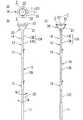
以下、図1〜図3を参照して、本発明を適用した実施形態1の電球交換器具1について説明する。ここで、図1(A)〜(C)は、電球交換器具1を説明する図であり、(A)は平面図、(B)は正面図、(C)は一部破断正面図である。図2は、電球交換器具1のヘッド(電球保持体)20が球状電球WA(実線で図示)又は扁平電球WB(二転鎖線で図示)を保持した状態を示す正面拡大図である。図3(A)〜(C)は、ヘッド20の拡大図であり、(A)は平面図、(B)は球状電球WA、扁平電球WB(いずれも二点鎖線で図示)を取り付けた状態の正面断面図、(C)は(A)中のA−A線矢視拡大図である。 Hereinafter, with reference to FIGS. 1-3, the light
ここで、電球交換器具1が交換対象(着脱対象)とする球状電球WA、扁平電球WBについて説明する。図2に示すように、球状電球WAは、天井Tに設けられたソケットSに螺合されるねじ部WAaと、下部が略半球状の電球本体WAbとを有している。球状電球WAとしては、例えば、電球型蛍光灯(パルックボール(登録商標))があげられる。一方、扁平電球WBは、球状電球WA用のソケットSとは異なるソケットSに螺合されるねじ部WBaと、下部が球形を上下方向の押し潰したような扁平形状の電球本体WBbとを有している。扁平電球WBとしては、例えば、レフ電球があげられる。これらの球状電球WA、扁平電球WBは、電球本体WAb,WBbよりも、ねじ部WAa,WBaの方が重く、重心が高い位置にあるため、交換中に姿勢を崩さないように、しっかりと保持することが肝要である。一方、電球本体WAb,WBbは、例えば、薄手のガラス、あるいはこれと同等の合成樹脂によって形成されていて、大きな力が作用した場合には、割れるおそれがあるので、必要以上の力が作用しないようにすることも肝要である。 Here, the spherical light bulb WA and the flat light bulb WB that are replaced (removed) by the light
なお、以下の説明で、特に球状電球WAと扁平電球WBとを区別する必要がない場合には、適宜、電球WA,WBといい、電球一般についていうときは、単に、電球という。
本実施形態の電球交換器具1は、手の届かない高所に露出状態で下向きにソケットSにねじ込まれている電球WA,WBを、椅子や踏み台等を使用することなく取り外し、また、新規のものを取り付ける器具、つまり、形状の異なる電球WA,WBのいずれも交換することができる器具である。また、電球交換器具1は、電球を横方向から把持する従来のものと比較して、交換時に電球WA,WBが割れにくい。また、従来のものと比較して、交換中に電球WA,WBの姿勢が変化しにくく、バランスを崩して落下する等の事故を有効に防止することができる。In the following description, when it is not particularly necessary to distinguish between the spherical light bulb WA and the flat light bulb WB, they are appropriately referred to as light bulbs WA and WB, and when referring to general light bulbs, they are simply referred to as light bulbs.
The light
以下、電球交換器具1について詳述する。 Hereinafter, the
電球交換器具1は、図1に示すように、中心軸Cに沿って棒状に長く延びて、使用時には長手方向を上下方向に向けた立てた状態で使用される操作棒10と、この操作棒10の上端(先端)に開口部を上に向けて取り付けられた椀状のヘッド(電球保持体)20とを備えている。 As shown in FIG. 1, the
操作棒10は、中心軸Cに沿って延びる棒本体12と、この棒本体12の下端に設けられたグリップ11とを有している。 The
棒本体12は、例えば、ステンレス,アルミニウム等の金属パイプによって形成されていて、中心軸Cに直交する断面が円形に形成されている。棒本体12は、図3に示すように、上端12aが後述するヘッド20の取付部24に嵌合されている。一方、図1に示すように、棒本体12の下端(基端部)には、例えば、ゴム等によって滑り止めが施されたグリップ11が取り付けられている。ユーザは、電球交換器具1を使用する際には、図1(B)に示すように、この操作棒10を立てた状態でグリップ11を把持し、操作棒10を左回り(矢印L方向)に回転させることにより、ヘッド20を左回り(電球WA,WBの緩み方向)に回転させ、また、右回り(矢印R方向)に回転させることで、ヘッド20を右回り(電球WA,WBの締め付け方向)に回転させることができる。 The
ヘッド20は、図2に示すように、操作棒10の上端に固定されており、椀状に形成されたヘッド本体21と、滑り止め部としての粘着部22と、緩衝部材23とを有している。 As shown in FIG. 2, the
ヘッド本体21は、中心軸Cを中心とした回転体によって、上方に向けて開口された椀状に形成されており、機能的に4つの部分、すなわち、下方から上方に向かって順に、取付部24、下部25、中間部26、上部27とに分かれている。ヘッド本体21は、例えば、合成樹脂(プレスチック)によって形成されている。 The head
取付部24は、内側に、下方に向けて開口する嵌合穴24aが形成されていて、この嵌合穴24aに、上述の棒本体12の先端部12aが挿入されて嵌合されている。 A fitting hole 24a that opens downward is formed on the inside of the mounting
ヘッド本体21の内周面は、中心軸Cからの距離(中心軸Cを基準とした半径)が、上側に位置する部分ほど大きくなるように形成されていて、下方から順に、下部25の内周面である球状電球支持面25aと、中間部26の内周面である扁平電球支持面26aと、上部27の内周面である緩衝部材支持面27aとが連続して形成されている。 The inner peripheral surface of the head
球状電球支持面25aは、球状電球WAの電球本体WAbの下部の形状に倣って、略球面の一部によって形成されている。このため、球状電球WAは、電球本体WAbの下部が、球状電球支持面25aに密着して広い面積で略下方から支持されることになり、球状電球WAの交換時に、球状電球支持面25aから電球本体WAbに作用する力を分散させて、電球本体WAbを割れにくくすることができる。球状電球支持面25aの上端縁25bは、扁平電球支持面26aとの境界線を構成するものであり、内側に向かって凸状の円形に形成されている。 The spherical light
扁平電球支持面26aは、扁平電球WBの電球本体WBbの側部の形状に倣って、球状電球支持面25aの上端縁25bに沿った環状に形成されている。扁平電球支持面26aは、球状電球支持面25aの上端側を外側に押し広げたように形成されており、図3(B)に示す断面形状においても、電球本体WBbの側部の形状に倣った曲線状に形成されている。このため、扁平電球WBは、電球本体WBbの側部が、扁平電球支持面26aに密着して広い面積で略斜め下方から支持されることになり、球状電球WBの交換時に、扁平電球支持面26aから電球本体WBbに作用する力を分散させて、電球本体WBbを割れにくくすることができる。球状電球支持面25aの上端縁26bは、緩衝部材支持面27aとの境界線を構成するものであり、円形に形成されている。 The flat
緩衝部材支持面27aは、上端縁26bを介して扁平電球支持面26aに連続する環状に形成されている。本実施形態においては、緩衝部材支持面27aは、上端縁26bを介して扁平電球支持面26aに滑らかに連続するように構成されている。このため、上端縁26bは、形状的には区別できるものではないが、扁平電球WBの電球本体WBbに接触する面である扁平電球支持面26aのうちの最上位に位置する部分を上端縁26bと決めている。このように決めると、上端縁26bの上側に位置する緩衝部材支持面27aは、電球本体WBbの側部に接触することなく、上側に位置する部分ほど側部との間の隙間が広くなる。緩衝部材支持面27aの上端は、周端縁27bとなっている。 The buffer
上述のように、ヘッド本体21の内周面は、機能上、2箇所の上端縁25b,26bを境界として、下方から順に3つ部分、すなわち、球状電球支持面25a、扁平電球支持面26a、緩衝部材支持面27aに分割されている。そして、これら3つの面に対しては、球状電球WAは、その電球本体WAbが球状電球支持面25aにのみ接触し、扁平電球WBは、その電球本体WBbが扁平電球支持面26aにのみ接触するようになっている。 As described above, the inner peripheral surface of the head
図3(B)に示すヘッド20の深さXは、重みのある球状電球WAであっても、落下させることなく保持するのに最低限必要な深さに設定されている。また、電球WA,WBを交換するとき、ヘッド本体21の周端縁27bがソケットSを設けてある天井Tに当接しない深さXに設定されている。 The depth X of the
さらに、ヘッド20の深さXと外径Yは、天井Tに設けられたソケットSに電球WA,WBを着脱する際、ソケットSと電球WA,WBのねじ部WAa,WBaとをユーザが下から見上げたときに、ソケットSの入口とねじ部WAa,WBaとが周端縁27bを覆う後述の緩衝部材23によって見えにくくならない寸法に設定されている。 Further, the depth X and the outer diameter Y of the
ここで、球状電球支持面25aは、球状電球WAの電球本体WAbを略下方から、また、扁平電球支持面26aは、扁平電球WBの電球本体WBbを略斜め下方から支持することはできるが、上述のように、交換時の電球WA,WBは、比較的高い位置に重心があるので、交換時の電球WA,WBを安定した正しい姿勢に保持することは困難である。例えば、電球WA,WBは、交換時に上述の操作棒10が傾斜した場合には、姿勢を崩して、極端な場合には落下するおそれがある。なお、正しい姿勢とは、電球WA,WBの中心軸が、電球交換器具1の中心軸Cと一致することをいう。 Here, the spherical light
本実施形態では、次に説明する粘着部22によって、電球WA,WBが正しい姿勢を維持するようにしている。 In the present embodiment, the light bulbs WA and WB are maintained in the correct posture by the
粘着部(滑り止め部)22は、図3(A)に示すように、ヘッド20の内周面を周方向に等分する位置のそれぞれに設けられている。本実施形態では、2等分する位置のそれぞれに設けられている。粘着部22は、例えば、粘着剤が両面に塗布された両面テープをヘッド本体21の内周面に貼着することで構成することができる。すなわち、粘着部22は、図3(C)に示すように、両面テープを適宜な長さに切って、一方の端部(上端)22aがヘッド本体21の上部27の周端縁27b近傍に位置し、中間部が緩衝部材支持面27aから上端縁26bを超えて扁平電球支持面26aに貼着され、さらに、上端縁25bを超えて球状電球支持面25aにまで延びるように貼着されて、他方の端部(下端)22bが上端縁25bよりも下方に位置するように構成されている。 As shown in FIG. 3A, the adhesive portion (slip prevention portion) 22 is provided at each position where the inner peripheral surface of the
粘着部22は、このように構成すると、扁平電球支持面26aと球状電球支持面25aとの双方に同時に簡単に設けることができる。また、粘着部22は、両面テープで構成すれば、厚さを薄くすることができるので、球状電球WAの電球本体WAbを粘着部22に粘着させた際に、電球本体WAbの他の部分が球状電球支持面25aに密着されるのを妨げない。同様に、扁平電球WBの電球本体WBbを粘着部22に粘着させた際に、電球本体WBbの他の部分が扁平電球支持面26aに密着されるのを妨げない。また、粘着部22は、扁平電球支持面26aにおける中心軸Cから最も遠い部分(上端縁26a近傍)と球状電球支持面25aにおける中心軸Cから最も遠い部分(上端縁25a近傍)との双方に設けることができ、これにより、ヘッド20の回転を、粘着部22を介して電球WA,WBに伝達する際に、大きな回転力を伝達することが可能である。また、粘着部22が、ヘッド本体21の内周面を周方向に2等分する位置のそれぞれに設けてあるので、粘着部22が1箇所である場合や、2箇所ではあるが2等分する位置ではない場合と比較して、ヘッド20の回転を粘着部22を介して電球WA,WBに円滑に伝達することができる。また、粘着部22が2箇所に設けてあるので、球状電球支持面25a又は扁平電球支持面26aで支持した電球本体WAb,WBbを2箇所の粘着部22に粘着させることで、電球WA,WBの姿勢を正しく保持するとともに、例えば、電球WA,WBの交換中に操作棒10が傾斜した場合であっても、姿勢を崩すことがなく、もちろん落下するおそれもない。さらに、粘着部22のうちの、緩衝部材支持面27aに位置する部分は、後述する緩衝部材23を固定するのに利用することができる。 If comprised in this way, the
ところで、天井TのソケットSから電球WA,WBを取り外した後、及び電球WA,WBをソケットSに取り付けた後には、これら電球WA,WBを粘着部22から剥離させることが必要となるため、粘着力は大きすぎないことが要求される。一方、電球WA,WBの姿勢を正しく保持したり、ヘッド20に回転力を確実に電球WA,WBに伝達したりするためには、小さすぎないことが要求される。 By the way, after removing the light bulbs WA and WB from the socket S of the ceiling T and after attaching the light bulbs WA and WB to the socket S, it is necessary to peel off the light bulbs WA and WB from the
そこで、粘着部22は、粘着テープ22の粘着剤自体の粘着力が異なるものを使用したり、粘着テープの幅(ヘッド本体21の周方向に沿っての幅)を変更したり、配設箇所を2箇所ではなく3箇所以上にしたりすることで、全体としての粘着力を調整する。
例えば、粘着部22を、ヘッド本体21の内周面を周方向に3等分する位置のそれぞれに設けた場合には、2箇所の場合と比較して、全体としての粘着力は同じであっても、1箇所ごとの粘着部22の粘着力を小さくすることができるので、電球WA,WBを剥離しやすくすることができ、また、ヘッド20の回転を一層円滑に電球WA,WBに伝達できるとともに、電球WA,WBの姿勢をより安定させることが可能である。Therefore, the
For example, when the
なお、実際には、粘着テープの幅を適宜に設定することにより、粘着部22は、ヘッド本体21の内周面を周方向に2等分する位置にそれぞれ設ければ十分である。また、上述では粘着部22が緩衝部材支持面27aにも存在する場合を例に説明したが、粘着部22は、ここにはなくて、扁平電球支持面26aと球状電球支持面25aとに存在するようにしてもよい。 In practice, it is sufficient to provide the
緩衝部材23は、ヘッド本体21の上部27の周端縁27bを覆うように設けられている。緩衝部材23は、図3(C)に示すように、外側端部23aがヘッド本体21の上部27の外周面側に回り込み、中間部が周端縁27bを覆って、内側端部23bが上端縁26bと略同じかこれよりも少し上に位置するように配置されている。緩衝部材23は、この状態で、周端縁27bを全周にわたって覆うように構成されている。したがって、緩衝部材23のうちの、粘着部22に対応する部分は、この粘着部22によって固定されることになる。緩衝部材23は、例えば、スポンジによって構成されている。緩衝部材23は、その内側端部23bが扁平電球支持面26aにはかからないので、扁平電球支持面26aに扁平電球WBの電球本体WBbの側部が密着される際に、その妨げにならない。また、緩衝部材23のうちの、緩衝部材支持面27a上に位置する部分は、扁平電球支持面26aに扁平電球WBの電球本体WBbの側部が密着される際に、この密着される側部よりも少し上の側部と、緩衝部材支持面27aとの間に挟み込まれて圧縮される。これにより、扁平電球WBを一層確実の保持することが可能となる。このように、緩衝部材23がヘッド本体21の上部27の周端縁27bを覆うように設けられているので、特に、電球WA,WBをソケットSから取り外す際に、周端縁27bが直接、電球本体WAb,WBbに当たって、割ったりするおそれがない。 The
以上の構成の電球交換器具1によって球状電球WAをソケットSに着脱する動作を説明する。 The operation of attaching and detaching the spherical light bulb WA to the socket S by the light
球状電球WAをソケットSに取り付ける場合、ヘッド20の球状電球支持面21により球状電球WAを支持し、さらに粘着部22に貼着する。これにより、球状電球WAは、ヘッド20によって正しい姿勢で保持される。この状態で、球状電球WAのねじ部WAaをソケットSに挿入して、操作棒10を右回りに回転させる。すると、ヘッド20と球状電球WAは、互いに滑ることなく、粘着部22によって一体に回転して、球状電球WAはソケットSにねじ込まれる。 When the spherical light bulb WA is attached to the socket S, the spherical light bulb WA is supported by the spherical light
球状電球WAをソケットSから取り外す場合、球状電球WAにヘッド20の球状電球支持面21を球状電球WAに当接させて、さらに、粘着部22を球状電球22に粘着させる。その後、操作棒10を左回りに回転させる。ヘッド20と球状電球WAは、互いに滑ることなく、粘着部22によって一体に回転して、球状電球WAはソケットSから外れる。球状電球WAはソケットSから外れた後も、粘着部22によって正しい姿勢が保持され、かつ、姿勢を崩して落下するようなことはない。 When the spherical light bulb WA is removed from the socket S, the spherical light
この一連の交換動作において、電球交換器具1は、球状電球支持面21が球状電球WAの電球本体WAbの下部に倣って形成されているので、電球本体WAbに加わる押圧力を分散させることができ、これにより、球状電球WAが割れにくくなる。また、フィット感と安定感があるので、球状電球WAをソケットSに対して安定した正しい姿勢で回転させて交換し易いという特徴がある。 In this series of replacement operations, the
一方、扁平電球WBをソケットSに取り付ける場合、扁平電球支持面22によって扁平電球WBを保持し、さらに、扁平電球WBを粘着部22に粘着させる。これにより、扁平電球WBは、ヘッド20によって正しい姿勢で保持される。扁平電球WBのねじ部WBbをソケットSに挿入して、操作棒10を右回りに回転させる。すると、ヘッド20と扁平電球WBは、粘着部22によって互いに滑ることなく一体に回転する。この結果、扁平電球WBはソケットSにねじ込まれる。 On the other hand, when the flat light bulb WB is attached to the socket S, the flat light bulb WB is held by the flat light
扁平電球WBをソケットSから取り外す場合、ソケットSにねじ込まれている扁平電球WBに扁平電球支持面22を押し付け、さらに、粘着部22を扁平電球WBに粘着する。その後、操作棒10を左回りに回転させる。ヘッド20と扁平電球WBは、粘着部22によって互いに滑ることなく一体に回転する。この結果、扁平電球WBはソケットSから外れる。 When the flat bulb WB is removed from the socket S, the flat
この一連の交換動作において、電球交換器具1は、扁平電球支持面26aが、扁平電球WBの電球本体WBbの側部の形状に倣って形成されていて電球本体WBbに密着するので、電球本体WBbに加わる押圧力を分散させて、電球本体WBbを割れにくくすることができる。また、フィット感と安定感があるので、扁平電球WBをソケットSに対して安定した正しい姿勢を保持した状態で回転させて交換し易いという特徴がある。 In this series of replacement operations, the
また、電球交換器具1は、ソケットSにねじ込まれている電球WA,WBを取り外す際に、周端縁27bが電球本体WAb,WBbにぶつかるようなことがあっても、周端縁27aを覆う緩衝部材23が電球本体WAb,WBbにぶつかるので、電球本体WAb,WBbが割れにくい。
<実施形態2>In addition, when removing the bulbs WA and WB screwed into the socket S, the
<
図4〜図6を参照して、本発明を適用して実施形態2の電球交換器具2について説明する。なお、ヘッド(電球保持体)20については、実施形態1のものと同様であるので説明は適宜、説明は省略する。 With reference to FIGS. 4-6, the light
ここで、図4(A)〜(C)は、電球交換器具2を説明する図であり、(A)は平面図、(B)は正面図、(C)は一部破断正面図である。図5は、空回り機構14を説明する図であり、(A)は可動軸12Dを回転させていないときの正面断面図、(B)は(A)中のG−G線矢視断面図、(C)は可動軸12Dを、電球WA,WBの緩み方向(矢印L方向:左回り)に回転させたときの正面断面図、(D)は(C)中のH−H線矢視断面図、(E)は可動軸12Dを、電球WA,WBの締め付け方向(矢印R方向:右回り)に回転させて空転しているときの正面断面図、(F)は(E)中のJ−J線矢視断面図である。図6は、操作棒10の長さを調節する接続機構15を説明する図であり、(A)は正面図、(B)は(A)の断面図(正面断面図)、(C)は右側面図、(D)は(C)の断面図(右側面断面図)、(E)は(C)中のK−K矢視断面図、(F)は(C)中のM−M矢視断面図、(G)は左側面図、(H)は(G)の断面図(左側面断面図)である。なお、図6においては、断面のハッチングは省略している。 Here, FIGS. 4 (A) to 4 (C) are diagrams for explaining the light
図4に示すように、操作棒10は、長さ方向に3つの分割軸12A,12B,12Cに分割されている。各分割軸12A,12B,12Cは、接続機構15によって、着脱自在に接続されている。さらに、最上位の分割軸12Aは、長さ方向に可動軸12Dと従動軸12Eとに分割されて空回り機構14によって接続されている。 As shown in FIG. 4, the
空回り機構14は、ユーザが操作棒10を回転させる側となる可動軸12Dとヘッド20が設けられた従動軸12Eとの間に設けられている。 The idling
図5(A)〜(F)に示すように、空回り機構14は、可動軸12Dの上端部に太径に形成されたフランジ部31と、従動軸12Eに設けられてフランジ部31を包持する包持部32と、フランジ部31の外周と包持部32の内周の間に保持されたC字状のばね部材33とによって構成されている。 As shown in FIGS. 5A to 5F, the idling
包持部32は、弾性変形してフランジ部31とばね部材33とを受け入れて、包持して可動軸12Dと従動軸12Eとを接続するようになっている。 The holding
フランジ部31の外周の一部分(略1/4周分)には、駆動溝34が形成されている。駆動溝34は、可動軸12Dの右回り(図4(B),図5(F)中の矢印R方向)に深さが徐々に深くなり、終端が段部34aになっている。包持部32の内周には、従動軸12Eの右回り(図4(B),図5(D)中の矢印R方向)に深さが一定で、ばね部材33を保持する保持溝36(略1/2周分)と、保持溝36に連続して従動軸12Eの右回りに深さが徐々に深くなるばね逃げ溝38とが形成されている。ばね逃げ溝38の終端が段部38aになっている。図5(B),(D)に示す状態では、駆動溝34とばね逃げ溝38とは、段部34a,38a相互を一致させた状態で互いに対向するように形成されている。 A
C字状のばね部材33は、フランジ部31を締め付ける方向に弾性を備えている。ばね部材33の一端には、駆動溝34とばね逃げ溝38との段部34a,38aに同時に当接(係合)する頭部33aが形成されている。 The C-shaped
以上の構成の空回り機構14は、球状電球WAと扁平電球WBとのいずれの電球WA,WBであっても、電球WA,WBをソケットSから取り外すとき、図5(A)、(B)に示す状態から、図5(C)、(D)に示すように、可動軸12Dを矢印L方向に回転させると、駆動溝34の段部34aがばね部材33の頭部33aに当接し、ばね部材33の尾部33bが保持溝36の段部36aに当接(係合)して、従動軸12Eも矢印L方向に回転する。従動軸12Eは、矢印L方向に回転して電球WA,WBをソケットSから取り外す。 The
電球WA,WBをソケットSに取り付けるとき、図5(A),(B)に示す状態、あるいは、図5(C)、(D)に示す状態から可動軸12Dを矢印R方向に回転させると、弾性によって可動軸12Dを締め付けているばね部材33が可動軸12Dと一体に矢印R方向に回転して、ばね部材33の頭部33aがばね逃げ溝38の段部38aを押圧して摩擦力により従動軸12Eを矢印L方向に回転させ、電球WA,WBをソケットSにねじ込む。 When the light bulbs WA and WB are attached to the socket S, when the
電球WA,WBがソケットSにねじ込まれて、それ以上回転しなくなった状態で、可動軸12Dをさらに矢印R方向に回転させると、従動軸12Eの回転が阻止されて、可動軸12Dが回転する。すると、図5(E),(F)に示すように、可動軸12Dを締め付けているばね部材33は、回転阻止されている従動軸12Eのばね逃げ溝38の段部38aに当接して回転を阻止される。したがって、可動軸12Dのみ矢印R方向に回転する。この結果、可動軸12Dの過回転力は、従動軸12Eに伝達されることがなく、電球WA,WBを無理に回転させてソケットSにねじ込みすぎてとれなくなったり、割れたりするおそれを少なくすることができる。 When the
図4に示すように、操作棒10は、長さ方向に3分割されて、分割された分割軸12A,12B,12Cの端部相互の間に、分割軸相互を着脱可能に接続する接続機構15が設けられている。接続機構15は、3本の分割軸12A,12B,12Cのうち、1〜3本を自由に使用できるようにして、電球WA,WBの取り付け高さ位置に合わせて、操作棒10の長さを調節できるようになっている。 As shown in FIG. 4, the operating
操作棒10は、相互の接続部分が断面楕円形のパイプ状に形成されている。接続機構15は、図4(C)において、分割された3つの分割軸12A,12B,12C相互を接続するため、各分割軸12A,12B,12Cの間に設けられている。2つの接続機構15は、同一機構であるので、1番上の分割軸12Aと上から2番目の分割軸12Bとを接続する接続機構15について説明をして、他の接続機構15の説明は、省略する。このため、以下、1番上の分割軸12Aを上位の分割軸12A、上から2番目の分割軸12Bを下位の分割軸12Bと言う。 The
上位の分割軸12Aの下端部分12Aaは、下位の分割軸12Bの上端部分12Baに挿入できるように細く形成された細径部12Abになっている。上位の分割軸12Aの中間部分と細径部12Abとの境目は、段部12Acになっている。上位の分割軸12Aの下端部分12Aaを下位の分割軸12Bの上端部分12Baに挿入したとき、分割軸12A,12B相互は、段部12Acに受け止められて、接続された状態になる。しかも、両方の分割軸12A,12Bとも断面が楕円に形成されているので、電球WA,WBの交換時に、操作棒10を回しても、分割軸12A,12B相互は、互いに空回りすることなく、一体に回転するようになっている。 The lower end portion 12Aa of the
分割軸12A,12B相互をつなげたとき、分割軸12A,12B相互が抜けないように、抜け止め部材41が下位の分割軸12Bの上端部分12Baに設けられている。抜け止め部材41は、樹脂製であり、断面楕円形に形成されて、扁平な部分に軸方向に沿ってスリット41aが形成され、上位の分割軸12Aの下端部分12Aaと下位の分割軸12Bの上端部分12Baとに密着させて双方の分割軸12A,12Bを遊びがないように把持して、接続するようになっている。 A retaining
そして、抜け止め部材41は、内側に突設された突起42が下位の分割軸12Bの上端部分12Baに形成された係合孔43に係合して、下位の分割軸12Bの上端部分12Baから上方へ抜けないように、下位の分割軸12Bの上端部分12Baに固定的に設けられている。 The retaining
抜け止め部材41は、上位の分割軸12Aの下端部分12Aaを受け入れるようになっている。抜け止め部材41は、上位の分割軸12Aの下端部分12Aaを受け入れたとき、上位の分割軸12Aが上方へ抜けないようにするため、抜け止め部材41に沿って形成された舌片状の弾性を有するロック片44の突起45が上位の分割軸12Aに形成されたロック孔46に係合するようになっている。ロック片44は、引き起こすことができるように抜け止め部材41に形成されている。上位の分割軸12Aの下端部分12Aaには、上位の分割軸12Aを抜け止め部材41に挿入したとき、ロック片44の突起45をロック孔46に案内する案内斜面47が形成されている。 The retaining
以上の構成の接続機構15による、分割軸12A,12B相互の接続、分離を説明する。抜け止め部材41は、突起42が係合孔43に係合されて、下位の分割軸12Bの上端部分12Baに取り付けられて一体化されている。この状態で、上位の分割軸12Aの下端部分12Aaを抜け止め部材41に挿入し、上位の分割軸12Aの細径部12Abを下位の分割軸12Bの上端部分12Baに挿入する。このとき、上位の分割軸12Aと下位の分割軸12Bとが断面楕円形に形成されているので、上位の分割軸12Aの回転方向の向きを、下位の分割軸12Bの向きに合わせて、細径部12Abを下位の分割軸12Bの上端部分12Baに挿入する。挿入に伴って、ロック片44が一旦外側に弾性変形して、ロック片44の突起45が案内斜面47に案内されてロック孔46に係合する。これによって、上位の分割軸12Aと下位の分割軸12Bとが接続されたことになる。 Connection and separation between the
その後、下位の分割軸12Bを握って回転させると、上位の分割軸12Aと下位の分割軸12Bとが断面楕円形に形成されていることと、突起42が係合孔43に係合し、ロック片44の突起45がロック孔46に係合していることとによって、上位の分割軸12Aと下位の分割軸12Bとが一体に回転する。
双方の分割軸12A,12Bを分離するには、ロック片44を上位の分割軸12Aから離れる方向に撓ませて弾性変形させる。すると、ロック片44の突起45がロック孔46から抜けて、上位の分割軸12Aを抜け止め部材41から抜き取ることができ、双方の分割軸12A,12Bを分離することができる。Thereafter, when the lower divided
In order to separate both the
以上のように、電球交換器具2に接続機構15を設けると、操作棒10の長さを電球WA,WBの交換をし易い長さに調節することができて、ソケットSから取り外す電球WA,WBに電球交換器具2をぶつけて電球WA,WBを割るおそれを少なくすることができる。
<実施形態3>As described above, when the
<Embodiment 3>
図7を参照して、本発明を適用して実施形態3について説明する。 With reference to FIG. 7, Embodiment 3 will be described by applying the present invention.
図7は、電球WA,WBよりも小型の小型電球(不図示)を交換できる小型電球用ヘッド(小型電球保持体)51と、ロック機構52とを説明する図であり、(A)は平面図、(B)は正面断面図、(C)は(B)のロック機構52の右側面図である。 FIG. 7 is a diagram for explaining a small light bulb head (small light bulb holder) 51 that can exchange a small light bulb (not shown) smaller than the light bulbs WA and WB, and a
小型電球用保持体としての小型電球用ヘッド51は、扁平電球支持面26aに装着されて、小型電球を保持できるようにリング状に形成されている。小型電球用ヘッド51は、太径部51aと、細径部51bと、これらの境目に形成された段部51cと、小型電球保持孔59とで形成されている。 A small
小型電球保持孔59は、小型電球用ヘッド51を貫通する貫通孔である。小型電球保持孔59は、小型電球の形状に合わせて、下方に行くに従って直径が小さくなるように形成されている。なお、小型電球保持孔59にも、粘着部22が等間隔に2つ設けられていてもよい。 The small
ロック機構52は、小型電球用ヘッド51を扁平電球支持面22の先端部に着脱自在に固定するようになっている。ロック機構52は、ヘッド20の下部にはめ込まれたリング状のベース金具55と、ベース金具55に上下方向に回転自在に設けられたリング状のヘッド固定金具56と、ベース金具55の、ヘッド固定金具56の回転中心部56aに対して反対側に上下方向に回転自在に設けられたロック解除金具57と、一端がロック解除金具57の中間部分に回転自在に設けられ、他端がヘッド固定金具56の回転端部56bに係合する方形枠状のロック金具58とによって構成されている。 The
電球交換器具1で小型電球を交換するには、ヘッド20の扁平電球支持面26aに小型電球用ヘッド51をロック機構52によって取り付ける。その取り付け動作を説明する。 In order to replace the small light bulb with the light
まず、ヘッド固定金具56を扁平電球支持面26aから遠ざける方向に回転させておいて、扁平電球支持面26aに小型電球用ヘッド51を装着する。次に、ヘッド固定金具56を小型電球用ヘッド51に近付ける方向に回転させる。ロック解除金具57の回転端部57aを上方に回転させてロック解除金具57を上向きにして、ヘッド固定金具56の回転端部56aにロック金具58が係合できるようにする。 First, the
そして、ヘッド固定金具56の回転端部56bにロック金具58を係合させた状態で、ロック解除金具57の回転端部57aを下方に回転させてロック解除金具57を下向きにする。すると、ロック金具58は、ヘッド固定金具56の回転端部56bに係合したまま、下方に引かれる。そして、ロック金具58の回転中心58aが、ヘッド固定金具56の回転端部56bとロック解除金具57の回転中心57bとを結ぶ仮想線Lを横切ってヘッド20側に移動する。この結果、ロック金具58の回転中心58aがデッドポイントを超えたことになるので、ロック機構52は、ヘッド固定金具56で、小型電球用ヘッド51を扁平電球支持面26aに押し付けた、図7(B)に示すロック状態になる。 Then, in a state where the lock fitting 58 is engaged with the
電球交換器具1は、ロック機構52によって扁平電球支持面26aに押し付けられて固定された小型電球用ヘッド51の小型電球保持孔59に小型電球を保持させて容易に交換することができる。 The
電球交換器具1による小型電球の交換動作は、球状電球WAを交換するときの動作と同様であるので、その動作説明は省略する。 The replacement operation of the small light bulb by the light
小型ヘッド51をヘッド20から取り外すには、ロック解除金具57を図7(B)に示す状態から左回転させて、ロック金具58の回転中心58aを仮想線Lの左側から右側に移動させる。すると、ロック金具58をヘッド固定金具56の回転端部56bから外すことができる。そして、ヘッド固定金具56を、左回転させて小型ヘッド51から離間させると小型ヘッド51をヘッド20から外すことができる。 To remove the
以上のように、本電球交換器具1は、扁平電球支持面26aの先端部に小型ヘッド51をロック機構52によって着脱自在に固定できるようになっているので、小型ヘッド51によって小型電球を容易に交換することができる。 As described above, in the present
1,2 電球交換器具
10 操作棒
12 棒本体
12A,12B,12C 分割軸
12D 可動軸
12E 従動軸
14 空回り機構
15 接続機構
20 ヘッド(電球保持体)
21 ヘッド本体
22 粘着部(滑り止め部)
23 緩衝部材
25a 球状電球支持面
25b 球状電球支持面の上端縁
26a 扁平電球支持面
26b 扁平電球支持面の上端縁
27a 緩衝部材支持面
27b 周端縁
31 フランジ部
32 包持部
33 ばね部材
33a 頭部(他方の端部)
33b 尾部(一方の端部)
51 小型ヘッド
52 ロック機構
59 小型電球保持孔
WA 球状電球
WAa ねじ部
WAb 電球本体
WB 扁平電球
WBa ねじ部
WBb 電球本体DESCRIPTION OF
21
23
33b Tail (one end)
51
Claims (12)
Translated fromJapanese人手により下端側が回転操作される操作棒と、
前記操作棒の上端に椀状に設けられ、内周面において球状電球と扁平電球とを択一的に保持する電球保持体と、を備え、
前記電球保持体は、
前記内周面のうちの下側に設けられて、前記球状電球の電球本体の下部を略下方から支持する球状電球支持面と、
前記内周面のうちの上側に、前記球状電球支持面の上端縁に沿って環状に設けられて、前記扁平電球の電球本体の側部を略斜め下方から支持する扁平電球支持面と、
前記内周面を周方向に等分する位置のそれぞれに設けられ、支持状態の前記電球本体に接触して前記球状電球又は前記扁平電球の姿勢を安定させるとともに、前記電球保持体の回転を前記電球本体に伝達する複数の滑り止め部と、を有する、
ことを特徴とする電球交換器具。When exchanging a light bulb that is mounted downward and exposed to an unreachable high place,
An operating rod whose lower end is rotated manually by a hand;
A bulb holder that is provided in a bowl shape on the upper end of the operation rod, and that selectively holds a spherical bulb and a flat bulb on the inner peripheral surface;
The bulb holder is
A spherical bulb support surface that is provided on the lower side of the inner peripheral surface and supports a lower portion of the bulb body of the bulb from substantially below;
On the upper side of the inner peripheral surface, provided in a ring shape along the upper edge of the spherical bulb support surface, a flat bulb support surface that supports a side portion of the bulb body of the flat bulb from a substantially oblique lower side,
Provided at each position where the inner peripheral surface is equally divided in the circumferential direction, contacting the supported bulb main body to stabilize the posture of the bulb or flat bulb, and rotating the bulb holder A plurality of non-slip portions that transmit to the bulb body,
A light bulb replacement device characterized by that.
前記扁平電球支持面は、前記扁平電球の前記電球本体の側部の形状に倣って、前記球状電球支持面の上端側を外側に押し広げるようにして環状に形成されている、
ことを特徴とする請求項1に記載の電球交換器具。The spherical bulb support surface is formed by a part of a substantially spherical surface, following the shape of the lower part of the bulb body of the bulb.
The flat bulb support surface is formed in an annular shape so as to expand the upper end side of the spherical bulb support surface outward, following the shape of the side of the bulb main body of the flat bulb.
The light bulb replacement device according to claim 1.
ことを特徴とする請求項1又は2に記載の電球交換器具。The anti-slip portion is formed such that a portion located on the spherical bulb support surface and the flat bulb support surface is continuously formed across the upper edge of the spherical bulb support surface.
The light bulb replacement device according to claim 1 or 2, characterized in that:
ことを特徴とする請求項3に記載の電球交換器具。The non-slip portion is present at a portion farthest from the central axis of the bulb holder on the spherical bulb support surface and a portion farthest from the central axis on the flat bulb support surface.
The light bulb replacement device according to claim 3.
ことを特徴とする請求項1ないし4のいずれか1項に記載の電球交換器具。The non-slip part is constituted by an adhesive part to which the bulb body is detachably attached,
The light bulb replacement apparatus according to any one of claims 1 to 4, wherein
ことを特徴とする請求項5に記載の電球交換器具。The anti-slip portion is provided at each of the positions at which the inner peripheral surface of the bulb holder is divided into two equal parts in the circumferential direction.
The light bulb replacement apparatus according to claim 5.
ことを特徴とする請求項5に記載の電球交換器具。The anti-slip portion is provided at each of the positions at which the inner peripheral surface of the bulb holder is equally divided into three in the circumferential direction.
The light bulb replacement apparatus according to claim 5.
ことを特徴とする請求項1ないし7のいずれか1項に記載の電球交換器具。A buffer member that covers a peripheral edge at the upper end is attached to the bulb holder.
The light bulb replacement device according to any one of claims 1 to 7, characterized in that:
ことを特徴とする請求項1ないし8のいずれか1項に記載の電球交換器具。The operating rod is divided into a movable shaft on the lower end side and a driven shaft on the upper end side, and the overturning of the movable shaft when the light bulb is mounted between the upper portion of the movable shaft and the lower portion of the driven shaft. An idle mechanism that prevents force from being transmitted to the bulb through the driven shaft and the bulb holder;
The light bulb replacement device according to any one of claims 1 to 8, wherein
前記フランジ部の外周側と前記包持部の内周側との間に周方向に沿って設けられた溝部に配設されたばね部材と、有し、
前記ばね部材は、電球取り付け時の前記可動軸の回転に対しては、一方の端部を前記フランジ部側に係合させるとともに他方の端部を前記包持部側に係合させて、前記可動軸の回転をそのまま前記従動軸に伝達し、電球取り外し時の前記可動軸の回転に対しては、前記可動軸に前記過回転力が加わったときには、前記可動軸との間に滑りを発生させて前記可回転力が前記従動軸に伝達されるのを禁止する、
ことを特徴とする請求項9に記載の電球交換器具。The idler mechanism includes a flange portion provided on one of the upper portion of the movable shaft and the lower portion of the driven shaft, and a wrapping portion provided on the other side and covering the outer peripheral surface of the flange portion;
A spring member disposed in a groove provided along the circumferential direction between the outer peripheral side of the flange portion and the inner peripheral side of the holding portion;
For the rotation of the movable shaft when the light bulb is attached, the spring member engages one end portion with the flange portion side and the other end portion with the holding portion side, The rotation of the movable shaft is transmitted as it is to the driven shaft, and when the over-rotation force is applied to the movable shaft with respect to the rotation of the movable shaft when the light bulb is removed, slip occurs between the movable shaft and the movable shaft. And prohibiting the rotation force from being transmitted to the driven shaft,
The light bulb replacement device according to claim 9.
ことを特徴とする請求項1ないし10のいずれか1項に記載の電球交換器具。The operation rod is composed of a plurality of divided shafts divided in the length direction, and a connection mechanism is provided between the ends of two adjacent divided shafts to removably connect the divided shafts. Yes,
The light bulb replacement device according to any one of claims 1 to 10, wherein
前記小型電球保持体を前記扁平電球支持面に着脱可能に固定するロック機構と、を備えた、
ことを特徴とする請求項1ないし11のいずれか1項に記載の電球交換器具。A small bulb holder that has a small bulb holding hole for holding a bulb smaller than the spherical bulb and the flat bulb, and can be attached to and detached from the flat bulb support surface;
A locking mechanism for removably fixing the small bulb holder to the flat bulb support surface,
The light bulb replacement device according to any one of claims 1 to 11, wherein
Priority Applications (1)
| Application Number | Priority Date | Filing Date | Title |
|---|---|---|---|
| JP2009218489AJP5066151B2 (en) | 2009-09-24 | 2009-09-24 | Bulb changer |
Applications Claiming Priority (1)
| Application Number | Priority Date | Filing Date | Title |
|---|---|---|---|
| JP2009218489AJP5066151B2 (en) | 2009-09-24 | 2009-09-24 | Bulb changer |
Publications (2)
| Publication Number | Publication Date |
|---|---|
| JP2011070784Atrue JP2011070784A (en) | 2011-04-07 |
| JP5066151B2 JP5066151B2 (en) | 2012-11-07 |
Family
ID=44015891
Family Applications (1)
| Application Number | Title | Priority Date | Filing Date |
|---|---|---|---|
| JP2009218489AExpired - Fee RelatedJP5066151B2 (en) | 2009-09-24 | 2009-09-24 | Bulb changer |
Country Status (1)
| Country | Link |
|---|---|
| JP (1) | JP5066151B2 (en) |
Cited By (10)
| Publication number | Priority date | Publication date | Assignee | Title |
|---|---|---|---|---|
| EP2815175A4 (en)* | 2012-02-16 | 2015-03-04 | Frank Gatski | Apparatus for removing and installing elevated light bulbs |
| WO2015168084A1 (en)* | 2014-05-01 | 2015-11-05 | Gurwicz Joseph | Adapter for changing led light bulbs |
| WO2017147002A1 (en)* | 2016-02-22 | 2017-08-31 | Gr Ventures L.L.C. | Interchangeable adapter for changing led light bulbs |
| USD816442S1 (en) | 2016-02-22 | 2018-05-01 | Gr Ventures L.L.C. | Light bulb changer head |
| USD817125S1 (en) | 2016-04-15 | 2018-05-08 | Gr Ventures L.L.C. | Light bulb changer head |
| USD817126S1 (en) | 2016-06-10 | 2018-05-08 | Jg Technologies Llc | Light bulb changer head |
| USD817124S1 (en) | 2016-02-22 | 2018-05-08 | Gr Ventures L.L.C. | Light bulb changer holder |
| KR20180003255U (en)* | 2017-05-11 | 2018-11-21 | 백정훈 | Bulb change device |
| US10429040B2 (en) | 2014-05-01 | 2019-10-01 | Gr Ventures L.L.C. | Interchangeable adapter for changing LED light bulbs |
| CN115013770A (en)* | 2022-08-10 | 2022-09-06 | 临沂爱能者节能设备有限公司 | Combined signal lamp for ship |
Citations (10)
| Publication number | Priority date | Publication date | Assignee | Title |
|---|---|---|---|---|
| JPS4969572U (en)* | 1972-09-28 | 1974-06-17 | ||
| JPS52980U (en)* | 1975-06-20 | 1977-01-06 | ||
| JPS57130955U (en)* | 1981-02-10 | 1982-08-14 | ||
| JPH0381334U (en)* | 1989-12-13 | 1991-08-20 | ||
| JPH0652841A (en)* | 1992-06-19 | 1994-02-25 | Philips Electron Nv | Method for mounting of single-base lamp into lamp holder, single-base lamp designed for this purpose and lighting fixture provided with single-base lamp |
| JPH0714559A (en)* | 1993-06-28 | 1995-01-17 | Kosumotetsuku Saitoo:Kk | Bulb replacing apparatus |
| JPH08287882A (en)* | 1995-04-10 | 1996-11-01 | Hiromoto Kosha | Electric lamp replacing tool |
| JPH1027583A (en)* | 1996-07-10 | 1998-01-27 | Yoshio Mizumoto | Electric lamp replacement implement |
| JP2001348050A (en)* | 2000-06-07 | 2001-12-18 | Toyoda Gosei Co Ltd | Capper for tank |
| JP3152164U (en)* | 2009-04-28 | 2009-07-23 | 福代 古賀 | Light bulb exchanger |
- 2009
- 2009-09-24JPJP2009218489Apatent/JP5066151B2/ennot_activeExpired - Fee Related
Patent Citations (10)
| Publication number | Priority date | Publication date | Assignee | Title |
|---|---|---|---|---|
| JPS4969572U (en)* | 1972-09-28 | 1974-06-17 | ||
| JPS52980U (en)* | 1975-06-20 | 1977-01-06 | ||
| JPS57130955U (en)* | 1981-02-10 | 1982-08-14 | ||
| JPH0381334U (en)* | 1989-12-13 | 1991-08-20 | ||
| JPH0652841A (en)* | 1992-06-19 | 1994-02-25 | Philips Electron Nv | Method for mounting of single-base lamp into lamp holder, single-base lamp designed for this purpose and lighting fixture provided with single-base lamp |
| JPH0714559A (en)* | 1993-06-28 | 1995-01-17 | Kosumotetsuku Saitoo:Kk | Bulb replacing apparatus |
| JPH08287882A (en)* | 1995-04-10 | 1996-11-01 | Hiromoto Kosha | Electric lamp replacing tool |
| JPH1027583A (en)* | 1996-07-10 | 1998-01-27 | Yoshio Mizumoto | Electric lamp replacement implement |
| JP2001348050A (en)* | 2000-06-07 | 2001-12-18 | Toyoda Gosei Co Ltd | Capper for tank |
| JP3152164U (en)* | 2009-04-28 | 2009-07-23 | 福代 古賀 | Light bulb exchanger |
Cited By (17)
| Publication number | Priority date | Publication date | Assignee | Title |
|---|---|---|---|---|
| EP2815175A4 (en)* | 2012-02-16 | 2015-03-04 | Frank Gatski | Apparatus for removing and installing elevated light bulbs |
| AU2013221860B2 (en)* | 2012-02-16 | 2016-07-28 | Frank GATSKI | Apparatus for removing and installing elevated light bulbs |
| WO2015168084A1 (en)* | 2014-05-01 | 2015-11-05 | Gurwicz Joseph | Adapter for changing led light bulbs |
| US10429040B2 (en) | 2014-05-01 | 2019-10-01 | Gr Ventures L.L.C. | Interchangeable adapter for changing LED light bulbs |
| USD839064S1 (en) | 2016-02-22 | 2019-01-29 | Gr Ventures L.L.C. | Light bulb changer head |
| USD817124S1 (en) | 2016-02-22 | 2018-05-08 | Gr Ventures L.L.C. | Light bulb changer holder |
| USD839065S1 (en) | 2016-02-22 | 2019-01-29 | Gr Ventures L.L.C. | Light bulb changer head |
| USD839063S1 (en) | 2016-02-22 | 2019-01-29 | Gr Ventures L.L.C. | Light bulb changer head |
| USD816442S1 (en) | 2016-02-22 | 2018-05-01 | Gr Ventures L.L.C. | Light bulb changer head |
| USD840776S1 (en) | 2016-02-22 | 2019-02-19 | Gr Ventures L.L.C. | Light bulb changer head |
| USD840775S1 (en) | 2016-02-22 | 2019-02-19 | Gr Ventures L.L.C. | Light bulb changer head |
| WO2017147002A1 (en)* | 2016-02-22 | 2017-08-31 | Gr Ventures L.L.C. | Interchangeable adapter for changing led light bulbs |
| USD817125S1 (en) | 2016-04-15 | 2018-05-08 | Gr Ventures L.L.C. | Light bulb changer head |
| USD817126S1 (en) | 2016-06-10 | 2018-05-08 | Jg Technologies Llc | Light bulb changer head |
| KR20180003255U (en)* | 2017-05-11 | 2018-11-21 | 백정훈 | Bulb change device |
| KR200488005Y1 (en)* | 2017-05-11 | 2018-12-03 | 백정훈 | Bulb change device |
| CN115013770A (en)* | 2022-08-10 | 2022-09-06 | 临沂爱能者节能设备有限公司 | Combined signal lamp for ship |
Also Published As
| Publication number | Publication date |
|---|---|
| JP5066151B2 (en) | 2012-11-07 |
Similar Documents
| Publication | Publication Date | Title |
|---|---|---|
| JP5066151B2 (en) | Bulb changer | |
| US8973946B2 (en) | Multifunction ski pole | |
| EP2249074B1 (en) | Holder | |
| US20220262618A1 (en) | Light bulb changer | |
| US20110252546A1 (en) | Adapter for protective helmets | |
| US20210276175A1 (en) | Broken light bulb extractor, light bulb changer and anti-loosening pole adapter | |
| US11125292B1 (en) | Rigid friction brake tether | |
| JP5627095B2 (en) | Dental extraoral vacuum device | |
| US6892994B1 (en) | Three-fingered holder | |
| JP6386873B2 (en) | Microphone holder and microphone shock mount using the microphone holder | |
| CN215129052U (en) | Oral cavity sample collection system for physical examination | |
| JP5054074B2 (en) | Bulb changer | |
| JPH1027583A (en) | Electric lamp replacement implement | |
| CN218254100U (en) | Clamping device for intermediate product | |
| CN1856340A (en) | Devices for hanging and locking ropes for climbing | |
| KR200490692Y1 (en) | Insert grip with detachable bowling ball having detachable hook device | |
| JP2003272568A (en) | Bulb replacement equipment | |
| CN216590060U (en) | Convenient adjustable ball valve | |
| KR102533628B1 (en) | Balling ball insert grip | |
| CN212109738U (en) | Rotary positioning quick-release structure for long gun lamp | |
| CN111632355B (en) | Handheld pole device of stepping on of integral type bullet knot | |
| JP2019169456A (en) | Electric bulb and replacement jig of the same | |
| JP3164249U (en) | Tire installation / removal tool | |
| CN106974525A (en) | A kind of glass holder with fingerstall with resistant to breakage function | |
| JP2007205453A (en) | Umbrella supporting device |
Legal Events
| Date | Code | Title | Description |
|---|---|---|---|
| A977 | Report on retrieval | Free format text:JAPANESE INTERMEDIATE CODE: A971007 Effective date:20120423 | |
| A131 | Notification of reasons for refusal | Free format text:JAPANESE INTERMEDIATE CODE: A131 Effective date:20120508 | |
| A521 | Written amendment | Free format text:JAPANESE INTERMEDIATE CODE: A523 Effective date:20120706 | |
| TRDD | Decision of grant or rejection written | ||
| A01 | Written decision to grant a patent or to grant a registration (utility model) | Free format text:JAPANESE INTERMEDIATE CODE: A01 Effective date:20120731 | |
| A01 | Written decision to grant a patent or to grant a registration (utility model) | Free format text:JAPANESE INTERMEDIATE CODE: A01 | |
| A61 | First payment of annual fees (during grant procedure) | Free format text:JAPANESE INTERMEDIATE CODE: A61 Effective date:20120810 | |
| R150 | Certificate of patent or registration of utility model | Ref document number:5066151 Country of ref document:JP Free format text:JAPANESE INTERMEDIATE CODE: R150 Free format text:JAPANESE INTERMEDIATE CODE: R150 | |
| FPAY | Renewal fee payment (event date is renewal date of database) | Free format text:PAYMENT UNTIL: 20150817 Year of fee payment:3 | |
| R250 | Receipt of annual fees | Free format text:JAPANESE INTERMEDIATE CODE: R250 | |
| R250 | Receipt of annual fees | Free format text:JAPANESE INTERMEDIATE CODE: R250 | |
| LAPS | Cancellation because of no payment of annual fees |