JP2011067546A - Ultrasonic diagnostic apparatus and method for calculating elasticity index - Google Patents
Ultrasonic diagnostic apparatus and method for calculating elasticity indexDownload PDFInfo
- Publication number
- JP2011067546A JP2011067546AJP2009223159AJP2009223159AJP2011067546AJP 2011067546 AJP2011067546 AJP 2011067546AJP 2009223159 AJP2009223159 AJP 2009223159AJP 2009223159 AJP2009223159 AJP 2009223159AJP 2011067546 AJP2011067546 AJP 2011067546A
- Authority
- JP
- Japan
- Prior art keywords
- ultrasonic
- echo data
- diagnostic apparatus
- elasticity index
- ultrasonic diagnostic
- Prior art date
- Legal status (The legal status is an assumption and is not a legal conclusion. Google has not performed a legal analysis and makes no representation as to the accuracy of the status listed.)
- Granted
Links
Images


Classifications
- A—HUMAN NECESSITIES
- A61—MEDICAL OR VETERINARY SCIENCE; HYGIENE
- A61B—DIAGNOSIS; SURGERY; IDENTIFICATION
- A61B8/00—Diagnosis using ultrasonic, sonic or infrasonic waves
- A61B8/08—Clinical applications
- A61B8/0858—Clinical applications involving measuring tissue layers, e.g. skin, interfaces
- A—HUMAN NECESSITIES
- A61—MEDICAL OR VETERINARY SCIENCE; HYGIENE
- A61B—DIAGNOSIS; SURGERY; IDENTIFICATION
- A61B5/00—Measuring for diagnostic purposes; Identification of persons
- A61B5/02—Detecting, measuring or recording for evaluating the cardiovascular system, e.g. pulse, heart rate, blood pressure or blood flow
- A61B5/02007—Evaluating blood vessel condition, e.g. elasticity, compliance
- A—HUMAN NECESSITIES
- A61—MEDICAL OR VETERINARY SCIENCE; HYGIENE
- A61B—DIAGNOSIS; SURGERY; IDENTIFICATION
- A61B8/00—Diagnosis using ultrasonic, sonic or infrasonic waves
- A61B8/46—Ultrasonic, sonic or infrasonic diagnostic devices with special arrangements for interfacing with the operator or the patient
- A61B8/461—Displaying means of special interest
- A61B8/463—Displaying means of special interest characterised by displaying multiple images or images and diagnostic data on one display
- A—HUMAN NECESSITIES
- A61—MEDICAL OR VETERINARY SCIENCE; HYGIENE
- A61B—DIAGNOSIS; SURGERY; IDENTIFICATION
- A61B8/00—Diagnosis using ultrasonic, sonic or infrasonic waves
- A61B8/48—Diagnostic techniques
- A61B8/485—Diagnostic techniques involving measuring strain or elastic properties
- G—PHYSICS
- G10—MUSICAL INSTRUMENTS; ACOUSTICS
- G10K—SOUND-PRODUCING DEVICES; METHODS OR DEVICES FOR PROTECTING AGAINST, OR FOR DAMPING, NOISE OR OTHER ACOUSTIC WAVES IN GENERAL; ACOUSTICS NOT OTHERWISE PROVIDED FOR
- G10K11/00—Methods or devices for transmitting, conducting or directing sound in general; Methods or devices for protecting against, or for damping, noise or other acoustic waves in general
- G10K11/18—Methods or devices for transmitting, conducting or directing sound
- G10K11/26—Sound-focusing or directing, e.g. scanning
- G10K11/34—Sound-focusing or directing, e.g. scanning using electrical steering of transducer arrays, e.g. beam steering
- G10K11/341—Circuits therefor
- G10K11/345—Circuits therefor using energy switching from one active element to another
Landscapes
- Health & Medical Sciences (AREA)
- Life Sciences & Earth Sciences (AREA)
- Engineering & Computer Science (AREA)
- Physics & Mathematics (AREA)
- Medical Informatics (AREA)
- Animal Behavior & Ethology (AREA)
- Veterinary Medicine (AREA)
- Public Health (AREA)
- Biomedical Technology (AREA)
- Heart & Thoracic Surgery (AREA)
- Biophysics (AREA)
- Molecular Biology (AREA)
- Surgery (AREA)
- Pathology (AREA)
- General Health & Medical Sciences (AREA)
- Nuclear Medicine, Radiotherapy & Molecular Imaging (AREA)
- Radiology & Medical Imaging (AREA)
- Vascular Medicine (AREA)
- Cardiology (AREA)
- Physiology (AREA)
- Acoustics & Sound (AREA)
- Multimedia (AREA)
- Ultra Sonic Daignosis Equipment (AREA)
Abstract
Translated fromJapaneseDescription
Translated fromJapanese本発明は、超音波エコーによって、生体組織を観察する超音波診断装置に関し、さらに詳しくは、血管壁の歪みや弾性率等の弾性指標を計測する超音波診断装置及び弾性指標の算出方法に関する。 The present invention relates to an ultrasonic diagnostic apparatus for observing a living tissue with ultrasonic echoes, and more particularly to an ultrasonic diagnostic apparatus for measuring an elastic index such as a distortion of a blood vessel wall and an elastic modulus and a method for calculating an elastic index.
脳梗塞や脳出血に代表される脳血管障害や、心筋梗塞,狭心症等の虚血性心疾患による治療患者が急増している。脳血管障害や虚血性心疾患のほとんどは動脈硬化を基礎病変として発病することが知られている。このため、こうした疾患を予防するためには、動脈硬化の兆候を未然に察知して、生活習慣を改善することが重要である。 The number of patients treated for ischemic heart diseases such as cerebrovascular disorders such as cerebral infarction and cerebral hemorrhage, myocardial infarction and angina pectoris has been rapidly increasing. It is known that most cerebrovascular disorders and ischemic heart diseases are caused by arteriosclerosis as a basic lesion. Therefore, in order to prevent such diseases, it is important to detect signs of arteriosclerosis and improve lifestyle habits.
動脈硬化を検査するために血管の性状を非侵襲的に評価する方法としては、従来より、脈波伝達速度(PWV)や足関節上腕血圧比(ABI)等を測定する方法が知られている。こうした血圧の測定によって動脈の性状を評価する方法は、広範囲の動脈の性状を平均化した総合的な評価に用いられる。 As a method for noninvasively evaluating the properties of blood vessels in order to examine arteriosclerosis, methods for measuring pulse wave transmission speed (PWV), ankle brachial blood pressure ratio (ABI), and the like have been known. . Such a method of evaluating arterial properties by measuring blood pressure is used for comprehensive evaluation by averaging the properties of a wide range of arteries.
また、動脈硬化は血管壁が肥厚するとともに硬化した状態を言うが、症状が進行すると血管壁の一部分にプラークが生じ血管内腔が狭窄され、プラークが破裂することにより、血栓や塞栓が生じて、脳血管障害や虚血性心疾患が引き起こされることが知られている。このため、広範囲の動脈の平均的な性状だけでなく、血管壁の局所的な性状を評価する指標が求められており、動脈硬化の好発部位である頚動脈の内膜中膜複合体厚(maximum intima-media thickness; IMT)を超音波エコーによって測定する方法が注目を集めている。 Arteriosclerosis is a condition in which the blood vessel wall thickens and hardens, but as symptoms progress, plaques form in a portion of the blood vessel wall, the vessel lumen narrows, and the plaque ruptures, resulting in thrombus and embolism. It is known that cerebrovascular disorders and ischemic heart diseases are caused. Therefore, there is a need for an index for evaluating not only the average properties of a wide range of arteries but also the local properties of the vascular wall, and the thickness of the intima-media complex of the carotid artery, which is a common site of arteriosclerosis ( A method of measuring maximum intima-media thickness (IMT) by ultrasonic echo has been attracting attention.
また、近年では、頚動脈の血管壁の心拍に応じた変位を測定することによって、IMTだけでなく、スティフネスパラメータβや歪み(ストレイン)、ストレインレート、弾性率といった血管壁の弾性を示す指標(以下、弾性指標という)が動脈硬化検査に取り入れられている(特許文献1,2)。こうした弾性指標を得るためには、心拍に応じて変位する頚動脈の血管壁をトラッキングしながら、精度良く血管壁の変位を測定する必要がある。このため、頚動脈に対して2つの異なる角度から超音波ビームを照射して得られるエコーデータを用いることにより、頚動脈の血管壁を精度良くトラッキングできるようにした超音波診断装置が知られている(特許文献3)。 In recent years, by measuring the displacement of the vascular wall of the carotid artery according to the heart rate, not only the IMT, but also an index indicating the elasticity of the vascular wall, such as stiffness parameter β, strain (strain), strain rate, and elastic modulus (hereinafter referred to as “the stiffness”). Is referred to as an elasticity index) (
また、正確な弾性指標を得るためには、血管の中央を通る方向で血管壁の変位量やIMTを計測する必要がある。このため、2次元に超音波トランスデューサを配列した超音波プローブ(以下、2D超音波プローブという)を用いて、頚動脈の立体的なデータを取得し、頚動脈の中央を通る断面内でIMT等を測定するようにした超音波診断装置が知られている(特許文献4)。 In order to obtain an accurate elasticity index, it is necessary to measure the displacement amount and IMT of the blood vessel wall in the direction passing through the center of the blood vessel. For this reason, using an ultrasonic probe (hereinafter referred to as a 2D ultrasonic probe) in which two-dimensional ultrasonic transducers are arranged, three-dimensional data of the carotid artery is acquired, and IMT and the like are measured within a cross section passing through the center of the carotid artery. An ultrasonic diagnostic apparatus configured to do this is known (Patent Document 4).
さらに、超音波プローブを往復させながら頚動脈の断層画像を取得することにより、心拍に応じたIMTの変化量を算出する超音波診断装置が知られている(特許文献5)。 Furthermore, there is known an ultrasonic diagnostic apparatus that calculates a change amount of IMT according to a heartbeat by acquiring a tomographic image of the carotid artery while reciprocating an ultrasonic probe (Patent Document 5).
上述のように近年求められている弾性指標の算出には、頚動脈壁を高精度にトラッキングする必要がある。しかし、単に頚動脈壁を高精度にトラッキングするだけでは、再現性が良く、信頼性の高い弾性指標を算出することはできず、頚動脈壁の変位量及び変位速度に比べて十分なレートでエコーデータ(あるいはエコーデータからつくられる断層画像)を取得することが求められる。 As described above, in order to calculate an elasticity index that has been required in recent years, it is necessary to track the carotid artery wall with high accuracy. However, simply tracking the carotid artery wall with high accuracy cannot calculate an elastic index with good reproducibility and high reliability, and echo data at a sufficient rate compared to the displacement amount and displacement speed of the carotid artery wall. (Or a tomographic image created from echo data) is required to be acquired.
例えば、頚動脈壁の歪みεは、一心拍中の血管壁厚の最大値Hmaxと、最大値Hmaxと最小値minの差分ΔHとを用いて、ε=ΔH/Hmaxで表される。このため、頚動脈壁の心拍に応じた変位量及び変位速度に比べて、エコーデータの取得レートが低い場合には、取得したエコーデータ内で頚動脈壁を高精度にトラッキングできたとしても、一心拍中の血管壁厚の最大値や最小値を正確に算出することができず、歪みεは算出するたびに異なる値となって再現性が確保できない。 For example, the distortion ε of the carotid artery wall is expressed as ε = ΔH / Hmax using the maximum value Hmax of the vascular wall thickness during one heartbeat and the difference ΔH between the maximum value Hmax and the minimum value min. For this reason, when the acquisition rate of echo data is low compared to the displacement amount and displacement speed according to the heartbeat of the carotid artery wall, even if the carotid artery wall can be tracked with high accuracy in the acquired echo data, one heartbeat The maximum and minimum values of the inner vascular wall thickness cannot be calculated accurately, and the strain ε becomes a different value every time it is calculated, and reproducibility cannot be ensured.
したがって、頚動脈壁のトラッキングのために、特許文献3に記載されているように2方向から超音波ビームを照射して得られる2つのエコーデータを用いる場合には、エコーデータの取得レートは実質的に1/2に低下するので、信頼性の高い弾性指標を算出することは難しい。同様に、特許文献4に記載されているように2D超音波プローブを用いて頚動脈の3次元データを取得してからIMTや弾性指標を算出するときには、さらに高いレートでエコーデータを取得する必要がある。 Therefore, when using two echo data obtained by irradiating an ultrasonic beam from two directions as described in
さらに、IMTや弾性指標は、本来、同一の箇所について算出するべきものであり、特許文献4のように、異なる箇所で算出したIMTから信頼性の高い弾性指標を算出することは難しい。 Furthermore, the IMT and the elasticity index should originally be calculated for the same location, and as in
本発明は上述の問題点に鑑みてなされたものであり、頚動脈壁等の観察対象を高精度にトラッキングすると同時に、高フレームレートでエコーデータを取得し、信頼性の高い弾性指標を算出することができる超音波診断装置及び弾性指標算出方法を提供することを目的とする。 The present invention has been made in view of the above-described problems, and is capable of tracking an observation target such as a carotid artery wall with high accuracy, and simultaneously acquiring echo data at a high frame rate and calculating a highly reliable elasticity index. It is an object of the present invention to provide an ultrasonic diagnostic apparatus and an elasticity index calculation method capable of performing the above.
本発明の超音波診断装置は、超音波を送受信する複数の超音波トランスデューサと、各々の前記超音波トランスデューサに駆動信号を入力することにより、前記超音波トランスデューサの部分集合から超音波ビームを送信させるとともに、前記部分集合を前記超音波トランスデューサ2個分以上のピッチでずらし、かつ、直前に送信した前記超音波ビームとオーバーラップするように複数回前記超音波ビームを送信させる送信手段と、前記超音波ビームのエコーを受信することにより前記超音波トランスデューサが出力するエコー信号を受信する受信手段と、前記エコー信号をラインに沿ったエコーデータを生成するにエコーデータ生成手段と、前記エコーデータを複数フレーム分記憶する記憶手段と、前記エコーデータに基づいて、観察している組織の弾性指標を算出する弾性指標算出手段と、前記エコーデータに基づいて、前記観察部位の空間的または経時的な画像を生成するとともに、前記画像を前記弾性指標に応じて染色した弾性指標画像を生成する画像生成手段と、を備えることを特徴とする。 The ultrasonic diagnostic apparatus of the present invention transmits an ultrasonic beam from a subset of the ultrasonic transducers by inputting a driving signal to each of the ultrasonic transducers and a plurality of ultrasonic transducers that transmit and receive ultrasonic waves. And transmitting means for transmitting the ultrasonic beam a plurality of times so as to overlap the ultrasonic beam transmitted immediately before and shifting the subset with a pitch of two or more ultrasonic transducers. Receiving means for receiving an echo signal output from the ultrasonic transducer by receiving an echo of a sound wave beam; echo data generating means for generating echo data along the line from the echo signal; and a plurality of the echo data Storage means for storing frames, and observation based on the echo data An elasticity index calculating means for calculating an elasticity index of a tissue, and a spatial or temporal image of the observation site based on the echo data, and an elasticity index obtained by staining the image according to the elasticity index And an image generation means for generating an image.
また、フレームレートをFR(1/s)、1フレーム分の前記エコーデータを取得するまでに送信する前記超音波ビームの送信回数をN(回)、観察部位内における平均音速をVs(m/s)、前記組織の深さの最大値をD(cm)とするときに、前記送信回数NがN≦(1/FR)×(Vs×102/2D)の条件を満たすことを特徴とする。Further, the frame rate is FR (1 / s), the number of transmissions of the ultrasonic beam transmitted until acquisition of the echo data for one frame is N (times), and the average sound velocity in the observation region is Vs (m / s), where the maximum value of the tissue depth is D (cm), the number of transmissions N satisfies a condition of N ≦ (1 / FR) × (Vs × 102 / 2D). To do.
また、前記弾性指標を算出する関心領域が指定されたときに、前記関心領域の幅及び深さに応じて、前記式1の条件を満たすように送信回数Nを定めるとともに、前記ピッチを定めることを特徴とする。 Further, when the region of interest for calculating the elasticity index is designated, the number of transmissions N is determined so as to satisfy the
前記フレームレートFRが100以上であることを特徴とする。 The frame rate FR is 100 or more.
また、送信回数Nが58以下で前記1フレームを構成することが好ましい。 Further, it is preferable that the number of transmissions N is 58 or less to constitute the one frame.
また、前記超音波トランスデューサは2次元に配列されていることが好ましい。 The ultrasonic transducers are preferably arranged two-dimensionally.
また、方位方向5mm、レンズ方向5mm以上の範囲について前記エコーデータを生成し、かつ、前記送信回数Nが58以下であることが好ましい。 Further, it is preferable that the echo data is generated for a range of 5 mm in the azimuth direction and 5 mm or more in the lens direction, and the number N of transmissions is 58 or less.
また、血管を観察するときに、血管の中心軸方向に沿って、血管の中心軸を通る断面に寄与するエコーデータを抽出し、前記断面内で前記弾性指標を算出するとともに、前記弾性指標画像を生成することが好ましい。 Further, when observing a blood vessel, the echo data contributing to the cross section passing through the central axis of the blood vessel is extracted along the direction of the central axis of the blood vessel, the elasticity index is calculated in the cross section, and the elasticity index image Is preferably generated.
また、血管を観察している最中に前記血管が移動した場合に、前記血管の移動量を算出し、前記移動量に応じて同一の断面についてのエコーデータを抽出することにより、前記弾性指標を算出するとともに、前記弾性指標画像を生成することが好ましい。 In addition, when the blood vessel moves while observing the blood vessel, the elasticity index is calculated by calculating the movement amount of the blood vessel and extracting echo data for the same cross section according to the movement amount. Preferably, the elasticity index image is generated.
また、前記弾性指標は、前記組織の歪みまたは前記歪みから算出される値であることが好ましい。 The elasticity index is preferably a strain of the tissue or a value calculated from the strain.
また、前記弾性指標算出手段は、あるフレームについて前記ライン毎にエコーデータの波形の特徴に応じて複数の代表点を定め、他のフレームについてライン毎に前記代表点の位置を同定することにより、各々の前記代表点を複数フレーム間でトラッキングし、その後、代表点間距離をフレーム毎に算出し、前記代表点間距離の最大値と最大変化量に基づいて前記代表点間の組織の歪みを算出することを特徴とする。 Further, the elasticity index calculation means determines a plurality of representative points according to the characteristics of the waveform of the echo data for each line for a certain frame, and identifies the position of the representative point for each line for other frames, Each representative point is tracked between a plurality of frames, and then the distance between representative points is calculated for each frame, and the distortion of the tissue between the representative points is calculated based on the maximum value and the maximum amount of change between the representative points. It is characterized by calculating.
本発明の弾性指標算出方法は、あるフレームについて、ライン毎にエコーデータの波形の特徴に応じて複数の代表点を定める代表点設定ステップと、他のフレームについて、ライン毎に前記代表点の位置を同定することにより、各々の前記代表点を複数フレーム間でトラッキングするトラッキングステップと、代表点間距離をフレーム毎に算出する代表点間距離算出ステップと、前記代表点間距離の最大値と最大変化量に基づいて前記代表点間の組織の歪みを算出する歪み算出ステップと、を備えることを特徴とする。 The elastic index calculation method according to the present invention includes a representative point setting step for determining a plurality of representative points for each line according to the characteristics of the waveform of the echo data for a certain frame, and the position of the representative point for each line for another frame. A tracking step for tracking each representative point between a plurality of frames, a representative point distance calculating step for calculating a distance between representative points for each frame, and a maximum value and a maximum of the distance between the representative points. A strain calculating step of calculating a strain of the tissue between the representative points based on the amount of change.
本発明によれば、頚動脈壁等の観察対象を高精度にトラッキングすると同時に、高フレームレートでエコーデータを取得し、信頼性の高い弾性指標を算出することができる。 According to the present invention, an observation target such as a carotid artery wall can be tracked with high accuracy, and at the same time, echo data can be acquired at a high frame rate and a highly reliable elasticity index can be calculated.
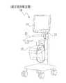
図1に示すように、超音波診断装置10は、超音波プローブ11から被検体内に超音波を発信し、そのエコーに基づいて被検体内の様子を画像化してモニタ14に表示する装置であり、プロセッサ装置12、操作部13等から構成される。 As shown in FIG. 1, the ultrasonic
超音波プローブ11は、複数の超音波トランスデューサ16(図2参照)によって超音波の送受信を行う探触子であり、超音波トランスデューサ16が配列された先端部分を被検者の表面に当接させて使用される。また、超音波プローブ11は、ケーブルによってプロセッサ装置12に接続されており、その動作はプロセッサ装置12によって制御される。 The
プロセッサ装置12は、超音波診断装置10の各部の動作を統括的に制御する制御装置であり、前述のように超音波プローブ11によって超音波を送受信させたり、受信したエコーから断層画像を生成しモニタ14に表示する。また、プロセッサ装置12は、断層画像としてBモード画像やMモード画像を生成、表示させる他に、観察している組織の歪みや弾性率等の弾性指標を算出し、こうした弾性指標を表示した歪み画像を生成し、リアルタイムにモニタ14に表示させる。 The
操作部13は、キーボードやポインティングデバイス、種々のボタンやダイヤル等からなり、医師等のオペレータは、この操作部13を用いて超音波診断装置10を操作する。例えば、オペレータは、操作部13を用いて、観察部位に応じた超音波診断装置10の動作様態に関わる各種設定値を指定したり、超音波プローブ11から発信する超音波ビームの焦点の深さを変更する。また、オペレータは、操作部13を用いて、関心領域(以下、ROIという)を指定する。さらに、被検者の血圧等、他の機器によって取得されるデータは、操作部13を用いて入力される。 The
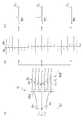
図2に示すように、超音波プローブ11は、複数の超音波トランスデューサ16を1列に配列したものである。超音波トランスデューサ16は、ピエゾ素子からなり、超音波を送受信する。また、各々の超音波トランスデューサ16は、後述する送信部22からマルチプレクサ21を介して入力される駆動信号に基づいて、個別にパルス駆動される。例えば、超音波プローブ11から超音波ビームを送信するときには、複数ある超音波トランスデューサ16の全てを同時に駆動するのではなく、連続した一部分の超音波トランスデューサ16を、各々タイミングを遅延させて駆動する。これにより、超音波プローブ11は、被検体内の所定箇所に、超音波トランスデューサ16複数個分の範囲に収束する幅広の超音波ビームを照射する。また、被検体内に送信した超音波ビームのエコーが超音波トランスデューサ16に入射すると、各超音波トランスデューサ16は、入射したエコーの振幅に応じたアナログのエコー信号を出力する。各超音波トランスデューサ16が出力するエコー信号は、マルチプレクサ21を介して後述する受信部23に入力される。 As shown in FIG. 2, the
プロセッサ装置12は、マルチプレクサ21、送信部22、受信部23、直交検波部24、メモリ26、エリアフォーマ27(エコーデータ生成手段)、画像生成部28、弾性指標算出部29、制御部30等から構成される。 The
マルチプレクサ21は、前述のように送信部22が出力する超音波トランスデューサ16の駆動信号を、複数ある超音波トランスデューサ16の中から必要な複数の超音波トランスデューサ16に選択的に入力する。また、マルチプレクサ21は、各超音波トランスデューサ16が出力するエコー信号を、各々個別に受信部23に入力する。 The
送信部22は、超音波トランスデューサ16に超音波を発生させる駆動信号を生成する。送信部22が生成する駆動信号は、複数の超音波トランスデューサ16のなかから、超音波トランスデューサ16の部分集合を選択的にパルス駆動させる。また、送信部22が生成する駆動信号は、超音波プローブ11から送信させる超音波ビームの形状や、焦点の深さ,大きさ等に応じて、選択的に駆動する各超音波トランスデューサ16を、それぞれタイミングを遅延させながら駆動する。さらに、送信部22は、上述の超音波トランスデューサ16の部分集合を、一定の方向に所定のピッチP(≧2)ずつずらしながら順に移動させ、間欠的に超音波ビームを送信させる。ピッチPの大きさは、1フレームあたりの超音波ビームの送信回数Nに応じて決定される。このとき、各送信毎の超音波ビームの一部をオーバーラップさせ、連続した超音波ビームによって取得されるデータが、前回と今回の送受信で少なくとも一つのライン(走査線)について再取得されるように決定される。なお、ここでは、定められたピッチPで超音波トランスデューサ16の部分集合を移動させたときに、超音波ビームに1ラインのオーバーラップができるように、1回の超音波ビームの送信のために駆動する超音波トランスデューサ16の個数(部分集合内の超音波トランスデューサの個数)を定めるとする。 The
受信部23は、マルチプレクサ21を介して各々の超音波トランスデューサ16が出力するエコー信号を受信し、直交検波部24に入力する。このとき、受信部23は、アナログのエコー信号を増幅するとともに、デジタルデータに変換する。 The receiving
直交検波部24は、受信部23から入力されたエコー信号の中心周波数と同じ周波数のsin波、cos波を掛け、それぞれローパスフィルタを通すことにより、振幅及び位相の情報を持つ複素ベースバンド信号に変換する。直交検波部24が出力する複素ベースバンド信号は、メモリ26に一時的に記憶され、エリアフォーマ27で利用される。 The
エリアフォーマ27は、メモリ26から複数の複素ベースバンド信号を読み出して整相加算することにより、1ライン毎に、被検体の深さ方向のデータ(以下、エコーデータ)を生成する。ここで生成されるエコーデータは、複数フレーム分がメモリ26に記憶され、画像生成部28や弾性指標算出部29で利用される。 The area former 27 reads out a plurality of complex baseband signals from the
画像生成部28は、所定数の一連のエコーデータに基づいて断層画像を生成する。例えば、画像生成部28は、1フレーム分のエコーデータからBモード画像を生成する。また、時間的に連続する複数フレーム分のエコーデータのうち、同一ラインのエコーデータからMモード画像を生成する。さらに、画像生成部28は、後述する弾性指標算出部29で算出された弾性指標を表示した弾性指標画像を生成する。弾性指標画像は、被検体の各部ついて算出された弾性指標の値に基づいて、Bモード画像等の断層画像の対応箇所を、所定のカラーマップにしたがってカラーリングすることにより生成される。こうして画像生成部28が生成した各種断層画像はモニタ14に表示される。 The
弾性指標算出部29は、例えば、複数フレーム分のエコーデータから、被検体内を細分化したエリア毎に、歪みεを算出する。まず、弾性指標算出部29は、あるフレームのエコーデータの波形の特徴から、ライン毎に代表点を定める(代表点設定ステップ)。次に、エコーデータの位相や振幅等に基づくパターンマッチングにより、所定フレーム分のエコーデータについて、ライン毎に各代表点の位置を同定することにより、各代表点を複数フレーム間でトラッキングする(トラッキングステップ)。その後、隣接する代表点間距離をフレーム毎に算出するとともに、代表点間距離の最大値ha、最小値hbを求める。同時に、代表点間距離の最大値haと最小値hbの差を算出し、各代表点間距離の最大変化量Δh(=ha−hb)とする(代表点間距離算出ステップ)。そして、弾性指標算出部29は、算出した代表点間距離の最大値haと代表点間距離の最大変化量Δhの値から、各代表点間の組織の歪みεを、ε=Δh/haにしたがって算出する(歪み算出ステップ)。また、オペレータによってROIが指定されたときには、弾性指標算出部29は、ROI内エリアについて、上述と同様に歪みεを算出する。こうして弾性指標算出部29が算出した歪みεの値は、各代表点の位置情報とともにメモリ26に記憶され、前述のように画像生成部28による弾性指標画像の生成に用いられる。 For example, the elasticity
制御部30は、操作部13からの入力を受けて、プロセッサ装置12の各部を制御する。また、制御部30は、1フレーム分のエコーデータを取得するために送信する超音波ビームの送信回数をN(回)、フレームレートをFR(1/s)、観察する部位の平均音速値をVs(m/s)、弾性指標を算出する組織の深さの最大値をD(cm)とするときに、下記数1の条件式を満たすように、超音波ビームの送信回数Nを決定する。特に、下記数1の条件式を満たす整数のうち、最大のものを超音波ビームの送信回数Nとすることが好ましい。 The
[数1]
N≦1/FR × (Vs×102)/2D[Equation 1]
N ≦ 1 / FR × (Vs × 102 ) / 2D
この数1の条件式は、以下のような意味を持つ。まず、人体内の平均音速値Vsは1400〜1600(m/s)程度であり、ほぼ一定値とみなせる。このため、超音波診断装置10の使用開始時に、この範囲内のある値に予め設定される。このとき、観察部位に応じて、超音波トランスデューサ16から観察したい部位の深さD(例えば頚動脈の最も深い位置)までの距離を超音波が往復するのに要する時間は、2D/(Vs×102)で表される。なお、制御部30は、ROIが指定されていないときには、断層画像の最下端の深さを上述のDの値として用い、ROIが指定されたときには、後述するようにROIの最も深い位置までの距離を上述のDとして用いる(図9参照)。The conditional expression of
一方、再現性の良い歪みεを算出するためには、一定時間T秒(例えば1心拍の秒数)内にM枚のBモード画像に相当するエコーデータを取得する必要があり、1フレーム(Bモード画像1枚)分のエコーデータの取得のために超音波ビームをN回送信するものとする。すると、一定時間T内に、N×M(回)の超音波ビームを送信する必要があることになる。 On the other hand, in order to calculate the distortion ε with good reproducibility, it is necessary to acquire echo data corresponding to M B-mode images within a certain time T seconds (for example, the number of seconds of one heartbeat), and one frame ( It is assumed that an ultrasonic beam is transmitted N times to acquire echo data for one B-mode image. Then, N × M (times) ultrasonic beams need to be transmitted within a certain time T.
しかし、前述のように、超音波の伝達に要する時間は、観察部位によって2D/(Vs×102)で定められるので、一定時間T(秒)内では、超音波ビームを最大T×(Vs×102)/2D回送信し、エコーデータを取得することができる。このため、N×Mは、T×(Vs×102)/2D以下の値である必要がある。すなわち、送信回数Nは、N≦(T/M)×(Vs×102)/2Dを満たす必要がある。ここで、T/M=1/(M/T)であり、M/TはフレームレートFRに他ならない。これにより上述の数1の条件式が得られる。なお、1フレームあたりの超音波ビームの送信回数Nが数1の条件式の右辺の値よりも大きくなると、一定時間T内に取得されるエコーデータが少なく、これに基づいて算出した歪みεの再現性が悪くなり、信頼性が低くなる。However, as described above, the time required for transmission of the ultrasonic wave is determined by 2D / (Vs × 102 ) depending on the observation site, so that the ultrasonic beam is maximum T × (Vs) within a certain time T (seconds). Echo data can be acquired by transmitting × 102 ) / 2D times. For this reason, N × M needs to be a value of T × (Vs × 102 ) / 2D or less. That is, the transmission count N needs to satisfy N ≦ (T / M) × (Vs × 102 ) / 2D. Here, T / M = 1 / (M / T), and M / T is nothing but the frame rate FR. As a result, the above-described
また、制御部30は、上述のようにして定めた超音波ビームの送信回数Nと、1ライン分のエコーデータが対応する幅と、生成する断層画像の幅に応じて、超音波トランスデューサ16の部分集合を移動させるピッチPを決定する。例えば、N=58、1ラインのエコーデータが0.3mmの幅に対応する断層画像に生成され、全体として33mm幅分の断層画像を生成するときには、ピッチPは、(33mm/0.3mm)÷58≒1.9以上の値で、最小の整数2に決定される。 In addition, the
以下、図3に示すように、超音波プローブ11を頚動脈32に沿って被検者の頚部31に当接させながら頚動脈壁の観察を行う例を挙げて、超音波診断装置10の動作様態を説明する。なお、頚動脈31の深さは概ね2〜4cmであるため、その観察に必要な深さDは概ね3cm程度である。また、前述のように人体内の平均音速Vsは1400〜1600m/sである。さらに、健常者の頚動脈壁は1心拍で0.5mm程度変位し、その変位速度は5〜8m/s程度であることが分かっている。このため、再現性の良く、信頼性の高い歪みεを算出するためには、前述の代表点の計測誤差を頚動脈壁の変位量0.5mmの10%程度以下に抑え、精密にトラッキングする必要がある。したがって、健常者の頚動脈を観察する場合、0.05(mm)÷5(m/s)=0.01(s)であり、0.05mmの変位を捉えるために、フレームレートFRは少なくとも100(1/s)であることが必要である。さらに、高血圧等のために、心拍に応じた血管壁の動きが速い被検者の場合には、FR=400(1/s)程度であることが望ましい。これらのことから、超音波診断装置10では、数1の条件式でD=3,Vs=1400,FR=400とし、1フレーム当たりの超音波ビームの送信回数Nを58としてある。 Hereinafter, as illustrated in FIG. 3, an example of observing the carotid artery wall while bringing the
また、超音波診断装置10は、110ラインについてエコーデータを生成する。さらに、超音波診断装置10は、1ラインにつき0.3mm幅のエリアに相当する画像を生成する。このため、超音波診断装置10が生成するBモード画像の幅方向は33mmとなる。また、前述のように、超音波診断装置10では1フレームあたりの超音波ビームの送信回数Nを58としたので、1回の超音波ビームの送信につき、少なくとも2ラインのエコーデータを生成すれば良いことになる。このため、前述の部分集合を移動ピッチPは2としてある。 Further, the ultrasonic
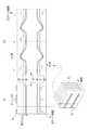
超音波診断装置10によって頚動脈31の観察を開始すると、送信部22は、超音波ビーム11から幅広の超音波ビームを被検体内に間欠的に送信させる。例えば、図4(A)に示すように、1列に配列された超音波プローブ16の一端からn番目の超音波トランスデューサ16を中心として、これと隣り合うものを合わせたn−1〜n+1番目の計3個の超音波トランスデューサ16の範囲に収束するように、n−3〜n+3番目までの計7個の超音波トランスデューサ16が各々遅延されながら駆動され、幅広の超音波ビーム36[n]が送信される。この超音波ビーム37nの焦点37は、超音波ビーム36[n]の幅がn−1〜n+1番目までの3個分の超音波トランスデューサ16の幅になる深さであり、主として焦点37近傍の組織からのエコーが超音波トランスデューサ16に入力される。このため、焦点37近傍の組織が鮮明に観察されることになる。なお、前述のように頚動脈32の深さが概ね2〜4cmであるため、焦点37の深さは例えば3cmに予め設定される。 When the observation of the
また、超音波ビーム36[n]のエコーは、全ての超音波トランスデューサ16に入力されるが、受信部23は、超音波の送信に用いたn−3〜n+3番目までの7個の超音波トランスデューサ16からエコー信号を選択的に受信する。そして、エリアフォーマ27は、複素ベースバンド信号に変換されたエコー信号に基づいてn−1,n,n+1番目の超音波トランスデューサ16に各々対応するラインLn−1,Ln,Ln+1のエコーデータを生成する。 The echoes of the ultrasonic beam 36 [n] are input to all the
次いで、図4(B)に示すように、ピッチPを2とし、駆動する超音波トランスデューサ16の部分集合を2素子分ずらして、n+2番目の超音波トランスデューサ16を中心として、n−1〜n+5番目の計7個の超音波トランスデューサ16を各々遅延しながら駆動する。これにより、n+2番目の超音波トランスデューサ16を中心として、n+1〜n+3の3個分の超音波トランスデューサ16の幅に収束する幅広の超音波ビーム36[n+2]が被検体内に送信される。また、受信部23は、超音波ビーム36[n]の場合と同様に、n−3〜n+5番目の計7個の超音波トランスデューサ16からエコー信号を選択的に受信する。そして、エリアフォーマ27は、複素ベースバンド信号に変換されたエコー信号に基づいて、n+1,n+2,n+3番目の超音波トランスデューサ16に各々対応するラインLn+1,Ln+2,Ln+3のエコーデータを生成する。 Next, as shown in FIG. 4B, the pitch P is set to 2, the subset of the
こうして幅広の超音波ビームの送信を繰返すことにより、超音波プローブ11は超音波トランスデューサ16の列幅分、被検体内を走査する。また、送信部22は、超音波ビーム36[n+2]を送信させるときに、超音波ビーム36[n]と超音波ビーム36[n+2]を斜線で示すようにオーバーラップさせる。このため、超音波診断装置10は、1回の超音波ビームの送信毎に3ライン分のエコーデータを生成するが、各回で1ライン分のエコーデータが重複し、超音波ビームの送信毎に、2ライン分のエコーデータを新たに生成する。したがって、幅広の超音波ビームを送信するとともに、部分集合(7個の超音波トランスデューサ)の移動ピッチPを2とすることで、1回の超音波ビームの送信に対して1ライン分のエコーデータを生成する一般的な超音波診断装置と比較して、超音波診断装置10は、約P倍(ここでは2倍)のレートでエコーデータを取得する。なお、重複するエコーデータは、超音波ビームの送信毎に生成される新たな2ライン分のエコーデータの位置合わせに利用される。 By repeating the transmission of the wide ultrasonic beam in this way, the
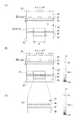
上述のように超音波ビームを送信した後には、選択的に受信した7個のエコーデータに基づいて、超音波ビームの送信毎に、以下のように3ライン分のエコーデータが生成される。図5(A)に示すように、超音波ビーム36[n]を送信したときに、ラインLn−1及びラインLn上に強い散乱体38a,38bがあるとする。このとき、選択的に受信されるエコーデータdn−3〜dn+3には、これらの散乱体38a,38bに対応したシグナル39a,39bが振幅が現れる。但し、散乱体38a,38bの位置から、n−3〜n+3番目の各超音波トランスデューサ16までの距離は各々に異なるため、シグナル39a,39bが現れる位置は、各超音波トランスデューサ16と各散乱体38a,38bからの距離に応じてエコー信号dn−3〜dn+3毎に異なる。 After transmitting the ultrasonic beam as described above, echo data for three lines is generated for each transmission of the ultrasonic beam based on the seven echo data selectively received as follows. As shown in FIG. 5A, it is assumed that
このため、図5(B)に示すように、エリアフォーマ27は、複素ベースバンド信号に変換されたエコー信号dn−3〜dn+3を、同じ点からのシグナルSn−1,Sn,Sn+1の位置が揃うように位相を整合して加算することにより、ラインLn−1,Ln,Ln+1の深さ方向に対応したエコーデータDn−1,Dn,Dn+1をそれぞれ生成する。例えば、ラインLnのエコーデータを生成するときには、ラインLn上の同じ点からのシグナルSnの位置が揃うように、エコー信号dn−3〜dn+3を時刻方向にシフトさせながら加算する。これにより、図5(C)に示すように、エコーデータDnには、ラインLn−1上の散乱体38bからのシグナル39b等他のライン上の点からのシグナルはほぼノイズレベル程度に平均化され、実質的にラインLn上の散乱体38aからのシグナル39aが強調されたシグナルだけ現れる。同様に、エコーデータDn−1,Dn+1には、それぞれラインLn−1,Ln+1上の散乱体からのシグナルを強調したシグナルだけが現れる。 Therefore, as shown in FIG. 5B, the area former 27 converts the echo signals dn-3 to dn + 3 converted into complex baseband signals into positions of the signals Sn-1, Sn, Sn + 1 from the same point. The echo data Dn−1, Dn, and Dn + 1 corresponding to the depth direction of the lines Ln−1, Ln, and Ln + 1 are respectively generated by matching and adding the phases so as to be aligned. For example, when generating the echo data of the line Ln, the echo signals dn-3 to dn + 3 are added while being shifted in the time direction so that the positions of the signals Sn from the same point on the line Ln are aligned. As a result, as shown in FIG. 5C, the echo data Dn averages signals from points on other lines such as the
図6(A)に示すように、画像生成部28は、上述のようにして生成されたエコーデータを並べ、各エコーデータの振幅を輝度としてマッピングすることにより、Bモード画像41を生成する。こうして生成したBモード画像41には頚動脈31の断面がグレースケールの濃淡として観察される。例えば、Bモード画像41からは、内腔42、内膜46、中膜47、外膜48等の組織からなる頚動脈31の断面層構造が観察される。 As shown in FIG. 6A, the
また、図6(B)に示すように、画像生成部28は、時間的に連続する複数フレーム分のBモード画像41に対応するエコーデータから、例えばラインLnの1ラインのエコーデータを所定の幅を持たせて時系列に並べ、各エコーデータの振幅を輝度としてマッピングすることにより、Mモード画像49を生成する。したがって、Mモード画像49には、時刻に応じた頚動脈31の変化が観察される。例えば、Mモード画像49では、心拍に応じて、各組織42,46〜48が深さ方向に変位し、頚動脈31が拡張,収縮を繰返す様子が観察される。 Further, as shown in FIG. 6B, the
こうして、画像生成部28が断層画像を生成すると同時に、弾性指標算出部29は、複数フレーム分のエコーデータに基づいて、頚動脈31の各組織の歪みεを算出する。説明の便宜のため、図7(A)に示すように、プラーク51が形成されている部分を観察しているものとする。このとき、弾性指標算出部29は、あるフレームのエコーデータをライン毎に読み出して、エコーデータの位相や振幅に基づいて代表点を定める。例えば、弾性指標算出部29は、ラインLn上のエコーデータにおいて、内腔42と内膜46の境界点、内膜46と中膜47の境界点、中膜47内に5点、中膜47と外膜48の境界点、外膜48と頚動脈31外の組織との境界点を、それぞれX0〜X8の代表点として定める。 Thus, at the same time as the
次に、図7(B)に示すように、複数フレーム分のエコーデータについて、代表点X0〜X8を定めたエコーデータをパターンマッチングし、各フレームのラインLn上に、代表点X0〜X8を同定する。これにより、代表点X0〜X8の深さを時系列にトラッキングしたトラッキングデータを一時的に作成する。そして、弾性指標算出部29は、トラッキングデータに基づいて、隣接する代表点間の距離を1心拍内で算出し、その最大値、最小値、及び最大変化量を求め、さらにこれらの値に基づいて代表点間にある組織の歪みεを算出する。 Next, as shown in FIG. 7B, pattern data is matched with echo data defining representative points X0 to X8 for echo data for a plurality of frames, and representative points X0 to X8 are placed on the line Ln of each frame. Identify. Thereby, tracking data obtained by tracking the depth of the representative points X0 to X8 in time series is temporarily created. Then, the elasticity
例えば、図7(C)に示すように、代表点間距離X1−X0を1心拍内で算出し、代表点間距離X1−X0の最大値h1aと最小値h1bを求める。同時に、代表点間距離X1−X0の最大変化量Δh1(=h1a−h1b)を算出する。そして、歪みε1=Δh1/h1aを算出する。ここで算出した歪みε1は、プラーク51の頂部における内膜42の心拍に応じた歪みを表している。 For example, as shown in FIG. 7C, the distance between representative points X1-X0 is calculated within one heartbeat, and the maximum value h1a and the minimum value h1b of the distance between representative points X1-X0 are obtained. At the same time, the maximum change amount Δh1 (= h1a−h1b) of the distance between representative points X1 to X0 is calculated. Then, the strain ε1 = Δh1 / h1a is calculated. The strain ε1 calculated here represents the strain corresponding to the heartbeat of the
また、例えば、代表点間距離X5−X4を1心拍内で算出し、代表点間距離X5−X4の最大値h5aと最小値h5bを求める。同時に、代表点間距離X5−X4の最大変化量Δh5を算出する。そして、歪みε5=Δh5/h5aを算出する。ここで算出した歪みε5は、プラーク51内部の心拍に応じた歪みを表している。 For example, the distance between representative points X5-X4 is calculated within one heartbeat, and the maximum value h5a and the minimum value h5b of the distance between representative points X5-X4 are obtained. At the same time, the maximum change amount Δh5 of the distance between representative points X5 to X4 is calculated. Then, the strain ε5 = Δh5 / h5a is calculated. The strain ε5 calculated here represents the strain corresponding to the heartbeat inside the
同様にして、弾性指標算出部29は、他の代表点間距離及びその最大値,最小値を算出し、さらに各代表点間距離の最大変化量を求める。そして、これらを用いて各代表点間の組織の歪みεを算出する。また、ここではラインLnのエコーデータを例に説明したが、弾性指標算出部29は、上述と同様にして、全ライン上で組織の歪みεを算出する。 Similarly, the elasticity
こうして弾性指標算出部29が歪みεを算出した後、図8に示すように、画像生成部28は、歪みεの大きさを表すカラーマップに応じてBモード画像41を染色し、弾性指標画像を生成する。例えば、図8(A)に示すように、ラインLn上の画素を代表点X0〜X8で区切り、カラーマップ52に応じて、これらの代表点間のエリアを染色する。なお、図8(A)では、便宜上、カラーマップ52を濃淡で表現しているが、実際は、例えば、歪みεが大きい(Hi)ほど青く、歪みεが小さい(Low)ほど赤く染色する。同様にして、画像生成部28は、Bモード画像41の全体を染色することにより、図8(B)に示すように、弾性指標画像53を生成する。こうして生成した弾性指標画像53からは、頚動脈31の断層構造が観察されると同時に、頚動脈壁の各組織の歪みεの大きさが観察される。また、Bモード画像41では判別できないが、弾性指標画像53では、プラーク51の内部に周辺よりも歪みεが大きく、脂質等の柔らかい組織51aがあることを読み取ることができる。 After the elasticity
上述のように、超音波診断装置10では、幅広の超音波ビームを送信し、1回の超音波ビームの送信につき複数ラインのエコーデータを生成するとともに、1回の超音波ビームの送信時に駆動する超音波トランスデューサ16の部分集合を2以上ずらす。このため、1回の超音波ビームの送信につき1ラインのエコーデータを生成する場合(いわゆるLine by Line)と比較して、高速に1フレーム分のエコーデータを取得することができ、FR=400もの高フレームレートを達成することができる。これにより、再現性が良く、信頼性の高い歪みεを算出することができる。 As described above, the ultrasonic
さらに、超音波診断装置10は、1フレームあたりの超音波ビームの送信回数Nが、数1の条件式を満たす値になっていることで、上述のような高フレームレートでエコーデータを取得しながらも、高精細な断層画像の生成に必要なライン数のエコーデータを取得することができる。 Further, the ultrasonic
なお、上述の実施形態では、1フレームのBモード画像41の全体について歪みεを算出し、弾性指標画像53を生成するが、これに限らず、Bモード画像41のうち、指定された一部分について歪みεを算出することが好ましい。例えば、図9(A)に示すように、オペレータがBモード画像41を観察しながら、ROI61を指定したとする。このとき、超音波診断装置10は、1フレームあたりの超音波ビームの送信回数を、ROI61の最も深い位置までの距離をDの値として数1の条件式を満たす最大の整数に変更する。そして、図9(B)に示すように、超音波診断装置10は、Bモード画像41の全体ではなく、指定されたROI61内について前述のように歪みεを算出する。ROI61内をカラーマップ52にしたがって染色した弾性指標画像62を表示する。 In the above-described embodiment, the strain ε is calculated for the entire B-
また、図9(B)では、ROI61以外の部分も表示するが、図9(C)に示すように、ROI61内だけを拡大表示した弾性指標画像63を生成し、表示しても良い。このように、指定されたROI61内について歪みεを算出し、ROI61の範囲内の弾性指標画像63を生成するときには、ROI61の部分についてだけエコーデータを生成することが好ましい。このとき、超音波診断装置10は、ROI61の幅W及びこの幅Wに含まれるライン数(超音波トランスデューサ16の数)に応じて、数1の条件式を達成できるように超音波ビームの送信回数を定めると同時に、定めた送信回数NとROI61の幅Wに応じて、移動ピッチPの幅を変更することが好ましい。このように、ROI61に応じて、送信回数Nや移動ピッチPを定めることで、上述の実施形態と同様、再現性が良く、信頼性の高い歪みεを算出、表示することができる。 In FIG. 9B, the portion other than the
なお、上述の実施形態のように、頚動脈31の性状を観察する場合、動脈硬化の初期病変の大きさは1〜10mm程度といわれているため、少なくとも幅5mm以上の範囲についてエコーデータを生成することが好ましい。また、指定されたROIがこの範囲よりも小さいときにも、指定されたROIを含む幅5mm以上の範囲についてエコーデータを生成することが好ましい。 Note that when observing the properties of the
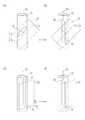
なお、上述の実施形態では、超音波トランスデューサ16が1列に配列された例を説明したが、図10(A)に示すように、超音波トランスデューサ16が2次元に配列された2D超音波プローブにおいても、上述の実施形態と同様にして、高フレームレートを達成し、再現性が良く、信頼性の高い歪みεを算出することができる。この場合、図10(B)に斜線で示すように、1回の超音波ビームを照射するために駆動する超音波トランスデューサ16の部分集合66(ここでは5×5の計25個)をx方向にピッチPxで移動させながらエコーデータを取得する。その後、一方の端まで走査したら、この部分集合66をy方向にピッチPyで移動させ、再びx方向にピッチPxで移動させながらエコーデータを取得する。これを繰返すことにより、2D超音波プローブにおいてもいわゆるLine by Lineでは達成できない高フレームレートを達成し、信頼性の高い歪みεの算出に必要なエコーデータを取得することができる。 In the above-described embodiment, an example in which the
また、こうして2D超音波プローブを用いることにより、超音波トランスデューサ16が1列に配列された超音波プローブ(以下、1D超音波プローブという)を用いる場合よりも、さらに再現性が良く、信頼性が高い歪みεを求めることができる。例えば、図11(A)に示すように、頚動脈31に対して超音波プローブが傾斜して当接されることがある。この場合、1D超音波プローブでは、線71に沿った頚動脈31の断面が観察されることになるため、頚動脈31の楕円形の断面72が観察されることになる。歪みεは、頚動脈31の中心軸73を通るラインのエコーデータから算出したときに最も再現性の良く、信頼性が高くなり、他のラインでは中心軸73から逸れる程、実際の歪みεからのずれが大きくなる。一方、2D超音波プローブでは、面74上の全ラインについて3次元的にエコーデータを取得するため、図11(B)に示すように、頚動脈31の径が最大になり、面74に垂直な断面を投影した線76に沿って頚動脈31の中心軸73を通る断面75のエコーデータを抽出し、これに基づいて歪みεを算出することができるので、常に再現性が良く、信頼性が高い。 Further, by using the 2D ultrasonic probe in this way, the reproducibility is better and the reliability is higher than in the case of using the ultrasonic probe in which the
また、図11(C)に示すように、超音波プローブの中心が頚動脈31の中心位置から横にずれて当接されることがある。この場合、1D超音波プローブでは、線71に沿って、中心軸73からずれた位置の断面77しか観察できないので、中心軸73を通るラインで算出するよりも歪みεの信頼性が低下する。一方、図11(D)に示すように、2D超音波プローブでは、3次元的に取得したエコーデータから、中心軸73を通る断面78のエコーデータを抽出することにより、常に再現性が良く、信頼性が高い歪みεを算出することができる。 In addition, as shown in FIG. 11C, the center of the ultrasonic probe may be abutted laterally from the center position of the
さらに、頚動脈31を観察している最中に、心拍や被検体の動き、オペレータの手振れ等によって頚動脈31が移動してしまうことがある。こうした場合にも、2D超音波プローブを用いれば、広範囲をカバーできるので断面75,78を走査する可能性が高くなるため、より容易に、再現性が良く、信頼性の高い歪みεを算出することができる。例えば、頚動脈31が3次元的に移動したときに、3次元的に取得されたエコーデータから、頚動脈31の移動前後のエコーデータに基づいて頚動脈31の移動量(例えば中心軸の移動量)を算出し、これに応じて頚動脈31の同一の断面のエコーデータを移動後のフレームのエコーデータから抽出する。そして、抽出したエコーデータから歪みεを算出すれば良い。なお、2D超音波プローブを用いるときには、1D超音波プローブとは異なる2D超音波プローブに特有の演算処理を行う回路等を予め設けておく必要がある。 Furthermore, while the
なお、上述のように2D超音波プローブを用いて頚動脈31の性状を観察する場合、前述のように動脈硬化の初期病変の大きさが1〜10mm程度といわれているため、少なくとも方位方向5mm×レンズ方向5mmの25mm2以上の範囲についてエコーデータを生成することが好ましい。ここで、レンズ方向とは、通常、超音波トランスデューサの前方に設けられる音響レンズが湾曲する方向(1D超音波プローブの場合のいわゆるエレベーション方向)であり、図10(A)ではy方向である。また、方位方向とは超音波トランスデューサの配列に沿った方向であり、レンズ方向に垂直な方向(1D超音波プローブの場合のいわゆるアジマス方向)であり、図10(A)ではx方向である。また、2D超音波プローブを用いる場合にも、指定されたROIの範囲が25mm2よりも小さいときには、指定されたROIを含む方位方向5mm×レンズ方向5mmの25mm2以上の範囲についてエコーデータを生成することが好ましい。さらに、この範囲のエコーデータを生成するときには、超音波ビームの送信回数Nが58以下であることが好ましい。In addition, when the property of the
また、上述の実施形態では、弾性指標の一例として歪みεを算出する例を説明したが、これに限らず、ストレインレート、スティフネスパラメータβ、弾性率等、他の弾性指標を算出し、算出した弾性指標の値を表示する弾性指標画像53を生成するようにしても良い。例えば、径方向の弾性率Erは、最大血圧と最小血圧の差をΔpとするときに、Er=Δp/εで算出される。また、円周方向の弾性率Eθは、心臓拡張末期での血管内半径rと血管壁厚hを用いて、Eθ=1/2×(r/h+1)×Δp/εで表される。このため、こうした弾性率Er,Eθを弾性指標として表示するときには、超音波診断装置10とは別個に最大血圧と最小血圧の差Δpを測定しておき、操作部13で超音波診断装置10にその値を入力する。また、血圧計と超音波診断装置10を接続し、被検体の血圧が自動入力しても良い。 In the above-described embodiment, an example in which the strain ε is calculated as an example of the elasticity index has been described. However, the present invention is not limited thereto, and other elasticity indices such as a strain rate, a stiffness parameter β, and an elasticity modulus are calculated and calculated. An elasticity index image 53 that displays the value of the elasticity index may be generated. For example, the elastic modulus Er in the radial direction is calculated as Er = Δp / ε, where Δp is the difference between the maximum blood pressure and the minimum blood pressure. Further, the elastic modulus Eθ in the circumferential direction is expressed by Eθ = ½ × (r / h + 1) × Δp / ε using the intravascular radius r and the vascular wall thickness h at the end diastole. For this reason, when displaying these elastic moduli Er and Eθ as elasticity indices, the difference Δp between the maximum blood pressure and the minimum blood pressure is measured separately from the ultrasonic
なお、上述の実施形態では、簡単のため1つの超音波トランスデューサ16につき1ラインのエコーデータを生成する例を説明したが、1つの超音波トランスデューサ16につき2以上のラインのエコーデータを生成しても良い。 In the above-described embodiment, an example in which one line of echo data is generated for one
なお、上述の実施形態では、1回の超音波ビームの送信のために、7個の超音波トランスデューサ16を駆動し、そのエコーから、3個の超音波トランスデューサ16に対応した3ライン分のエコーデータを生成するが、これに限らない。例えば、7より多くの超音波トランスデューサ16を駆動して1回の超音波ビームを送信させても良いし、7より少ない数の超音波トランスデューサ16を駆動して1回の超音波ビームを送信させても良い。また、1回の超音波ビームの送信毎に取得するエコーデータは、4ライン分以上のエコーデータを生成しても良い。 In the above-described embodiment, seven
また、上述の実施形態では、Bモード画像41を歪みεに応じて染色して弾性指標53を生成する例を説明したが、Mモード画像49等の他の画像を、歪みεに応じて染色した弾性指標画像を生成しても良い。 In the above-described embodiment, the example in which the B-
なお、上述の実施形態では、頚動脈31の観察する例を説明したが、これに限らず、超音波診断装置10は心臓のエコー検査にも好適に用いることができる。また、その他の部位の観察にも、超音波診断装置10を用いることができる。 In the above-described embodiment, an example in which the
10 超音波診断装置
11 超音波プローブ
12 プロセッサ装置
13 操作部
14 モニタ
16 超音波トランスデューサ
21 マルチプレクサ
22 送信部
23 受信部
24 直交検波部
26 メモリ
27 エリアフォーマ
28 画像生成部
29 弾性指標算出部
30 制御部
31 頚動脈
36 超音波ビーム
41 Bモード画像
49 Mモード画像
51 プラーク
52 カラーマップ
61 ROI(関心領域)DESCRIPTION OF
Claims (12)
Translated fromJapanese各々の前記超音波トランスデューサに駆動信号を入力することにより、前記超音波トランスデューサの部分集合から超音波ビームを送信させるとともに、前記部分集合を前記超音波トランスデューサ2個分以上のピッチでずらし、かつ、直前に送信した前記超音波ビームとオーバーラップするように複数回前記超音波ビームを送信させる送信手段と、
前記超音波ビームのエコーを受信することにより前記超音波トランスデューサが出力するエコー信号を受信する受信手段と、
前記エコー信号をラインに沿ったエコーデータを生成するにエコーデータ生成手段と、
前記エコーデータを複数フレーム分記憶する記憶手段と、
前記エコーデータに基づいて、観察している組織の弾性指標を算出する弾性指標算出手段と、
前記エコーデータに基づいて、前記観察部位の空間的または経時的な画像を生成するとともに、前記画像を前記弾性指標に応じて染色した弾性指標画像を生成する画像生成手段と、
を備えることを特徴とする超音波診断装置。A plurality of ultrasonic transducers for transmitting and receiving ultrasonic waves;
By inputting a drive signal to each of the ultrasonic transducers, an ultrasonic beam is transmitted from the subset of the ultrasonic transducers, and the subset is shifted at a pitch of two or more ultrasonic transducers, and Transmitting means for transmitting the ultrasonic beam a plurality of times so as to overlap with the ultrasonic beam transmitted immediately before;
Receiving means for receiving an echo signal output from the ultrasonic transducer by receiving an echo of the ultrasonic beam;
Echo data generating means for generating echo data along the line from the echo signal;
Storage means for storing the echo data for a plurality of frames;
Based on the echo data, an elasticity index calculating means for calculating an elasticity index of the tissue being observed;
Based on the echo data, an image generating unit that generates a spatial or temporal image of the observation site and generates an elasticity index image in which the image is stained according to the elasticity index;
An ultrasonic diagnostic apparatus comprising:
N≦(1/FR)×(Vs×102/2D)
の条件を満たすことを特徴とする請求項1記載の超音波診断装置。The frame rate is FR (1 / s), the number of transmissions of the ultrasonic beam transmitted until acquisition of the echo data for one frame is N (times), and the average sound velocity in the observation region is Vs (m / s) When the maximum value of the tissue depth is D (cm), the number of transmissions N is N ≦ (1 / FR) × (Vs × 102 / 2D)
The ultrasonic diagnostic apparatus according to claim 1, wherein:
前記関心領域の幅及び深さに応じて、前記式1の条件を満たすように送信回数Nを定めるとともに、前記ピッチを定めることを特徴とする請求項2記載の超音波診断装置。When the region of interest for calculating the elasticity index is designated,
The ultrasonic diagnostic apparatus according to claim 2, wherein the number of transmissions N is determined so as to satisfy the condition of Equation 1 according to the width and depth of the region of interest, and the pitch is determined.
他のフレームについて、ライン毎に前記代表点の位置を同定することにより、各々の前記代表点を複数フレーム間でトラッキングするトラッキングステップと、
代表点間距離をフレーム毎に算出する代表点間距離算出ステップと、
前記代表点間距離の最大値と最大変化量に基づいて前記代表点間の組織の歪みを算出する歪み算出ステップと、
を備えることを特徴とする弾性指標算出方法。A representative point setting step for determining a plurality of representative points according to the characteristics of the waveform of the echo data for each line for a certain frame,
For other frames, a tracking step of tracking each representative point between a plurality of frames by identifying the position of the representative point for each line;
A distance calculation step between the representative points for calculating the distance between the representative points for each frame;
A strain calculating step of calculating a strain of the tissue between the representative points based on the maximum value and the maximum change amount of the distance between the representative points;
An elastic index calculation method comprising:
Priority Applications (2)
| Application Number | Priority Date | Filing Date | Title |
|---|---|---|---|
| JP2009223159AJP5486257B2 (en) | 2009-09-28 | 2009-09-28 | Ultrasonic diagnostic apparatus and elasticity index calculation method |
| US12/923,401US20110077518A1 (en) | 2009-09-28 | 2010-09-20 | Ultrasonic diagnostic apparatus and method for calculating elasticity index |
Applications Claiming Priority (1)
| Application Number | Priority Date | Filing Date | Title |
|---|---|---|---|
| JP2009223159AJP5486257B2 (en) | 2009-09-28 | 2009-09-28 | Ultrasonic diagnostic apparatus and elasticity index calculation method |
Publications (2)
| Publication Number | Publication Date |
|---|---|
| JP2011067546Atrue JP2011067546A (en) | 2011-04-07 |
| JP5486257B2 JP5486257B2 (en) | 2014-05-07 |
Family
ID=43781108
Family Applications (1)
| Application Number | Title | Priority Date | Filing Date |
|---|---|---|---|
| JP2009223159AActiveJP5486257B2 (en) | 2009-09-28 | 2009-09-28 | Ultrasonic diagnostic apparatus and elasticity index calculation method |
Country Status (2)
| Country | Link |
|---|---|
| US (1) | US20110077518A1 (en) |
| JP (1) | JP5486257B2 (en) |
Cited By (5)
| Publication number | Priority date | Publication date | Assignee | Title |
|---|---|---|---|---|
| CN102805647A (en)* | 2011-06-03 | 2012-12-05 | 富士胶片株式会社 | Ultrasound diagnostic apparatus |
| KR101270639B1 (en) | 2011-11-29 | 2013-06-03 | 삼성메디슨 주식회사 | Diagnosis apparatus and operating method thereof |
| WO2013161228A1 (en)* | 2012-04-23 | 2013-10-31 | パナソニック株式会社 | Ultrasonic diagnostic device and ultrasonic diagnostic device control method |
| JP2014016187A (en)* | 2012-07-06 | 2014-01-30 | Ihi Aerospace Co Ltd | Method of measuring reduction rate of burning material |
| JP2022517640A (en)* | 2019-01-24 | 2022-03-09 | コーニンクレッカ フィリップス エヌ ヴェ | Methods and systems for investigating vascular properties |
Families Citing this family (14)
| Publication number | Priority date | Publication date | Assignee | Title |
|---|---|---|---|---|
| JP5292440B2 (en)* | 2011-06-03 | 2013-09-18 | 富士フイルム株式会社 | Ultrasonic diagnostic equipment |
| JP5844175B2 (en)* | 2012-02-20 | 2016-01-13 | 富士フイルム株式会社 | Ultrasonic diagnostic apparatus and ultrasonic image generation method |
| WO2013187335A1 (en)* | 2012-06-15 | 2013-12-19 | 株式会社東芝 | Ultrasound diagnostic device, computer program product, and control method |
| JP5806189B2 (en)* | 2012-09-25 | 2015-11-10 | 富士フイルム株式会社 | Ultrasonic diagnostic apparatus and ultrasonic image generation method |
| JP6000197B2 (en)* | 2012-09-27 | 2016-09-28 | 富士フイルム株式会社 | Ultrasonic diagnostic apparatus, ultrasonic image generation method and program |
| JP6000196B2 (en)* | 2012-09-27 | 2016-09-28 | 富士フイルム株式会社 | Ultrasonic diagnostic apparatus, sound speed determination method and program |
| JP5905808B2 (en)* | 2012-09-27 | 2016-04-20 | 富士フイルム株式会社 | Ultrasonic inspection apparatus, ultrasonic image data generation method and program |
| JP5873412B2 (en)* | 2012-09-28 | 2016-03-01 | 富士フイルム株式会社 | Ultrasonic diagnostic apparatus, sound speed determination method and program |
| JP5946427B2 (en)* | 2012-09-28 | 2016-07-06 | 富士フイルム株式会社 | Ultrasonic inspection apparatus, ultrasonic inspection method, program, and recording medium |
| CN104306019B (en)* | 2014-09-28 | 2016-06-01 | 安华亿能医疗影像科技(北京)有限公司 | Hand-held scanner utility appliance |
| US20160302761A1 (en)* | 2015-04-15 | 2016-10-20 | Samsung Medison Co., Ltd. | Ultrasound system for displaying stiffness of blood vessel |
| US11896427B2 (en)* | 2017-04-28 | 2024-02-13 | Shenzhen Mindray Bio-Medical Electronics Co., Ltd. | Ultrasonic imaging apparatus and method for detecting shear index of vascular wall using ultrasonic waves |
| CN114848011B (en)* | 2018-04-13 | 2025-06-17 | 深圳迈瑞生物医疗电子股份有限公司 | Ultrasonic imaging method and ultrasonic imaging device |
| CN116983013B (en)* | 2023-08-24 | 2025-08-26 | 逸超医疗科技(北京)有限公司 | Arterial plaque characteristic detection method, device and storage medium based on elastic imaging |
Citations (4)
| Publication number | Priority date | Publication date | Assignee | Title |
|---|---|---|---|---|
| JP2005074146A (en)* | 2003-09-03 | 2005-03-24 | Hiroshi Kanai | Method for measuring ultrasonic wave, and mechanism for generating the ultrasonic wave |
| JP2007006914A (en)* | 2005-05-30 | 2007-01-18 | Matsushita Electric Ind Co Ltd | Ultrasonic diagnostic equipment |
| JP2007282932A (en)* | 2006-04-19 | 2007-11-01 | Hitachi Medical Corp | Elastic image generation method and ultrasonic diagnostic apparatus |
| JP2008272025A (en)* | 2007-04-25 | 2008-11-13 | Toshiba Corp | Ultrasonic diagnostic equipment |
Family Cites Families (3)
| Publication number | Priority date | Publication date | Assignee | Title |
|---|---|---|---|---|
| US6685645B1 (en)* | 2001-10-20 | 2004-02-03 | Zonare Medical Systems, Inc. | Broad-beam imaging |
| JP4057524B2 (en)* | 2001-08-20 | 2008-03-05 | 独立行政法人科学技術振興機構 | Ultrasound diagnostic system |
| JP4892732B2 (en)* | 2007-03-28 | 2012-03-07 | 国立大学法人岐阜大学 | Blood vessel imaging method, blood vessel imaging system, and blood vessel imaging program |
- 2009
- 2009-09-28JPJP2009223159Apatent/JP5486257B2/enactiveActive
- 2010
- 2010-09-20USUS12/923,401patent/US20110077518A1/ennot_activeAbandoned
Patent Citations (4)
| Publication number | Priority date | Publication date | Assignee | Title |
|---|---|---|---|---|
| JP2005074146A (en)* | 2003-09-03 | 2005-03-24 | Hiroshi Kanai | Method for measuring ultrasonic wave, and mechanism for generating the ultrasonic wave |
| JP2007006914A (en)* | 2005-05-30 | 2007-01-18 | Matsushita Electric Ind Co Ltd | Ultrasonic diagnostic equipment |
| JP2007282932A (en)* | 2006-04-19 | 2007-11-01 | Hitachi Medical Corp | Elastic image generation method and ultrasonic diagnostic apparatus |
| JP2008272025A (en)* | 2007-04-25 | 2008-11-13 | Toshiba Corp | Ultrasonic diagnostic equipment |
Non-Patent Citations (1)
| Title |
|---|
| JPN6013023832; 長谷川英之、金井浩: '血管壁の弾性計測' 超音波医学 第35巻増刊号, 20080415, S184* |
Cited By (8)
| Publication number | Priority date | Publication date | Assignee | Title |
|---|---|---|---|---|
| CN102805647A (en)* | 2011-06-03 | 2012-12-05 | 富士胶片株式会社 | Ultrasound diagnostic apparatus |
| JP2012249848A (en)* | 2011-06-03 | 2012-12-20 | Fujifilm Corp | Ultrasound diagnostic device |
| KR101270639B1 (en) | 2011-11-29 | 2013-06-03 | 삼성메디슨 주식회사 | Diagnosis apparatus and operating method thereof |
| US8900144B2 (en) | 2011-11-29 | 2014-12-02 | Samsung Medison Co., Ltd. | Diagnosis apparatus and method of operating the same |
| WO2013161228A1 (en)* | 2012-04-23 | 2013-10-31 | パナソニック株式会社 | Ultrasonic diagnostic device and ultrasonic diagnostic device control method |
| JP2014016187A (en)* | 2012-07-06 | 2014-01-30 | Ihi Aerospace Co Ltd | Method of measuring reduction rate of burning material |
| JP2022517640A (en)* | 2019-01-24 | 2022-03-09 | コーニンクレッカ フィリップス エヌ ヴェ | Methods and systems for investigating vascular properties |
| JP7371105B2 (en) | 2019-01-24 | 2023-10-30 | コーニンクレッカ フィリップス エヌ ヴェ | Methods and systems for investigating vascular properties |
Also Published As
| Publication number | Publication date |
|---|---|
| JP5486257B2 (en) | 2014-05-07 |
| US20110077518A1 (en) | 2011-03-31 |
Similar Documents
| Publication | Publication Date | Title |
|---|---|---|
| JP5486257B2 (en) | Ultrasonic diagnostic apparatus and elasticity index calculation method | |
| JP3580627B2 (en) | Ultrasound diagnostic equipment | |
| JP3694019B2 (en) | Ultrasonic diagnostic apparatus and control method of ultrasonic diagnostic apparatus | |
| JP5501999B2 (en) | Ultrasonic diagnostic apparatus and elasticity index reliability determination method | |
| JP5158880B2 (en) | Ultrasonic diagnostic equipment | |
| JP4667394B2 (en) | Ultrasonic diagnostic equipment | |
| JP2005342006A (en) | Ultrasonic diagnostic apparatus, ultrasonic image processing apparatus, and ultrasonic signal processing program | |
| JP5384919B2 (en) | Ultrasonic diagnostic equipment | |
| JP5100084B2 (en) | Ultrasonic diagnostic apparatus, image processing apparatus, and image processing program | |
| JPWO2008038615A1 (en) | Ultrasonic diagnostic equipment | |
| WO2007034738A1 (en) | Ultrasonic diagnostic equipment | |
| JP5438722B2 (en) | Ultrasonic diagnostic equipment | |
| JP4667392B2 (en) | Ultrasonic diagnostic equipment | |
| JP2006115937A (en) | Ultrasonic diagnostic equipment | |
| JP2007222533A (en) | Ultrasonic diagnostic apparatus and ultrasonic image processing method | |
| JP5034054B2 (en) | Image processing apparatus, ultrasonic imaging apparatus including the same, and image processing method | |
| JP5400095B2 (en) | Ultrasonic diagnostic equipment | |
| JP5331313B2 (en) | Ultrasonic diagnostic equipment | |
| JP5346990B2 (en) | Ultrasonic diagnostic equipment | |
| JP5148203B2 (en) | Ultrasonic diagnostic equipment | |
| JP5154858B2 (en) | Ultrasonic diagnostic apparatus and ultrasonic probe used for ultrasonic diagnostic apparatus | |
| JP2004215968A (en) | Ultrasonic diagnostic apparatus and control method of ultrasonic diagnostic apparatus | |
| JP5462474B2 (en) | Ultrasonic diagnostic equipment | |
| JP2006289067A (en) | Ultrasonic diagnostic apparatus and control program therefor | |
| JP4745455B2 (en) | Ultrasonic diagnostic apparatus, ultrasonic image processing apparatus, and ultrasonic signal processing program |
Legal Events
| Date | Code | Title | Description |
|---|---|---|---|
| A621 | Written request for application examination | Free format text:JAPANESE INTERMEDIATE CODE: A621 Effective date:20120117 | |
| A977 | Report on retrieval | Free format text:JAPANESE INTERMEDIATE CODE: A971007 Effective date:20130516 | |
| A131 | Notification of reasons for refusal | Free format text:JAPANESE INTERMEDIATE CODE: A131 Effective date:20130522 | |
| A521 | Request for written amendment filed | Free format text:JAPANESE INTERMEDIATE CODE: A523 Effective date:20130722 | |
| TRDD | Decision of grant or rejection written | ||
| A01 | Written decision to grant a patent or to grant a registration (utility model) | Free format text:JAPANESE INTERMEDIATE CODE: A01 Effective date:20140129 | |
| A61 | First payment of annual fees (during grant procedure) | Free format text:JAPANESE INTERMEDIATE CODE: A61 Effective date:20140221 | |
| R150 | Certificate of patent or registration of utility model | Ref document number:5486257 Country of ref document:JP Free format text:JAPANESE INTERMEDIATE CODE: R150 | |
| R250 | Receipt of annual fees | Free format text:JAPANESE INTERMEDIATE CODE: R250 | |
| R250 | Receipt of annual fees | Free format text:JAPANESE INTERMEDIATE CODE: R250 | |
| R250 | Receipt of annual fees | Free format text:JAPANESE INTERMEDIATE CODE: R250 | |
| R250 | Receipt of annual fees | Free format text:JAPANESE INTERMEDIATE CODE: R250 | |
| R250 | Receipt of annual fees | Free format text:JAPANESE INTERMEDIATE CODE: R250 | |
| R250 | Receipt of annual fees | Free format text:JAPANESE INTERMEDIATE CODE: R250 | |
| R250 | Receipt of annual fees | Free format text:JAPANESE INTERMEDIATE CODE: R250 | |
| R250 | Receipt of annual fees | Free format text:JAPANESE INTERMEDIATE CODE: R250 | |
| R250 | Receipt of annual fees | Free format text:JAPANESE INTERMEDIATE CODE: R250 |