JP2011054778A - Heat exchanger using comb-type radiation unit - Google Patents
Heat exchanger using comb-type radiation unitDownload PDFInfo
- Publication number
- JP2011054778A JP2011054778AJP2009202618AJP2009202618AJP2011054778AJP 2011054778 AJP2011054778 AJP 2011054778AJP 2009202618 AJP2009202618 AJP 2009202618AJP 2009202618 AJP2009202618 AJP 2009202618AJP 2011054778 AJP2011054778 AJP 2011054778A
- Authority
- JP
- Japan
- Prior art keywords
- heat
- cooling fluid
- heat exchanger
- comb
- unit
- Prior art date
- Legal status (The legal status is an assumption and is not a legal conclusion. Google has not performed a legal analysis and makes no representation as to the accuracy of the status listed.)
- Pending
Links
Images


Landscapes
- Cooling Or The Like Of Electrical Apparatus (AREA)
- Cooling Or The Like Of Semiconductors Or Solid State Devices (AREA)
Abstract
Translated fromJapaneseDescription
Translated fromJapaneseこの発明は、CPU、集積回路、半導体素子等の各種電子部品、電子機器、そのほか各種電気機器などの放熱のために使用される熱交換器に関するものであり、特に放熱効率に優れ、少ない部品点数で製作が簡単な熱交換器に関するものである。 The present invention relates to a heat exchanger used for heat dissipation of various electronic components such as CPUs, integrated circuits and semiconductor elements, electronic devices, and other various electric devices, and is particularly excellent in heat dissipation efficiency and has a small number of components. It relates to a heat exchanger that is easy to manufacture.
よく知られているように、CPUや集積回路、半導体素子などの電子部品、電子機器や各種電気機器においては、放熱のために熱交換器を設けることが多い。この種の熱交換器の従来の代表的な例を図23に示す。 As is well known, a heat exchanger is often provided for heat dissipation in electronic components such as CPUs, integrated circuits, and semiconductor elements, electronic devices, and various electric devices. A conventional representative example of this type of heat exchanger is shown in FIG.
図23において、CPUや集積回路、半導体素子等の発熱源が熱的に接続されるベースプレート1は、アルミニウムや銅、あるいはそれらの合金等の熱伝導率が高い金属からなるものであり、そのベースプレート1上には、同様に熱伝導率が高い金属からなる長板状の複数の放熱フィン2が平行に立設されて、全体として熱交換器3が構成されている。なおこのような熱交換器の製作方法としては、押出しによりベースプレート1と放熱フィン2とを一体に形成する方法がコスト面から有利となるため、従来から広く適用されており、またベースプレートと放熱フィンとを別々に製造し、それらを接合することによって製造する方法も適用されている。 In FIG. 23, a
上述のような図23に示す従来の一般的な熱交換器を実際に使用するにあたっては、冷却用流体として例えば空気を、図23中の矢印Pで示すように一方の端部からベースプレート1の上面に沿いかつその長手方向(板状放熱フィン2の板面に沿う方向)に沿う方向に吹付け、隣り合う放熱フィン2同士の間に空気を流し、これにより発熱部品からベースプレート1を介して板状放熱フィン2に伝達された熱を大気中に放熱させる。 In actual use of the conventional general heat exchanger shown in FIG. 23 as described above, for example, air is used as a cooling fluid, and the
ところでこのような従来の一般的な熱交換器においては、板状放熱フィンの長さ(冷却用空気の風上側から風下側へ向かう方向の長さ)が長かったり、また隣り合う板状放熱フィンの相互間の間隔が小さければ、放熱フィンにおける風上側の部分の表面には冷たい空気が接するものの、放熱フィンの風下側の部分に接する空気は、既に温度上昇してしまっている状態となり、そのため全体として充分な放熱効果が得られないばかりでなく、特にベースプレートにおける放熱フィンの風下側の部分付近に近接して熱的に接続された発熱部品の放熱が充分に行われない、という問題がある。 By the way, in such a conventional general heat exchanger, the length of the plate-shaped radiating fin (the length in the direction from the windward side to the leeward side of the cooling air) is long, or adjacent plate-shaped radiating fins If the distance between the two is small, cold air is in contact with the surface of the leeward portion of the radiating fin, but the air that is in contact with the leeward portion of the radiating fin has already risen in temperature. In addition to not being able to obtain a sufficient heat dissipation effect as a whole, there is a problem that heat dissipation of heat-generating components that are thermally connected in the vicinity of the leeward side of the radiating fin in the base plate is not sufficiently performed. .
ここで、放熱フィンの相互間の間隔を大きくし、また冷却効率の向上を期待して多量の冷却用空気を高速で流すことも考えられるが、この場合には、隣り合う放熱フィンの間の中央部分を高速で空気が通り抜けるようになるだけであって、熱交換は充分に行なわれない。 Here, it is conceivable to increase the spacing between the radiating fins and to flow a large amount of cooling air at a high speed in order to improve the cooling efficiency. Only air can pass through the central part at high speed, and heat exchange is not performed sufficiently.
このように従来の一般的な図23に示す熱交換器では、充分な放熱効果が得られず、特に縦深に配置した複数の発熱部品を冷却する場合、とりわけ風下側の発熱部品を効果的に冷却することができなかったのである。 As described above, the conventional heat exchanger shown in FIG. 23 does not provide a sufficient heat dissipation effect. In particular, when cooling a plurality of heat generating components arranged vertically, the heat generating component on the leeward side is particularly effective. It was not possible to cool down.
このような問題を解決するために、既に特許文献1に示すような熱交換器が提案されている。この特許文献1に示される熱交換器は、基本的には、多数配設された板状放熱フィンの間を流れる冷却用空気の流速を下げて、温度境界層(すなわち冷却空気流がフィンの間を通過する際に、放熱フィンの表面に接して流れて熱が伝わることにより温度上昇する空気流の部分と、放熱フィンの熱の影響を受けない放熱フィンの表面から離れた空気流の部分とに形成される境界)が重なり合うようにすることによって、熱交換器の板状放熱フィンの表面の温度を、平均的に風下側(熱交換器出口側)の温度に近くなるようにすることができる、という考え方に基いてなされたものである。 In order to solve such a problem, a heat exchanger as shown in
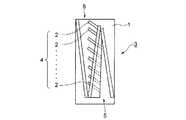
このような特許文献1の発明の熱交換器の構造のいくつかの例を図17〜図22に示す。これらのうち、代表的な図21の例について説明すれば、この例では、少なくとも一つの発熱部品が熱的に接続されるベースプレート1と、前記ベースプレート1上に、その長手方向に沿って所定の角度で並列状に配置されてベースプレート1と熱的に接続された複数の板状放熱フィン2(図21の例では縦方向に配列された5枚の板状放熱フィン2)からなる少なくとも一つのフィン部4(図21の例では、三つのフィン部4が横方向に配列されてこれらが全体としてフィン群を構成している)と、前記少なくとも一つのフィン部4のそれぞれに冷却用空気を送り込む入口部5と、前記少なくとも一つのフィン部4のそれぞれにおいて各板状放熱フィン2の間を冷却用空気が減速して概ね均一に流れるように、前記冷却用空気の流れを誘導する邪魔板部6および仕切り板部7と、冷却用空気を排出する排出口8とを設けて、全体として熱交換器3が構成されている。 Some examples of the structure of the heat exchanger of the invention of
上述のような特許文献1の提案の発明によれば、同一包絡体積で冷却能力が高く、風上風下方向で概ね温度差を生じることなく(すなわち風下でもフィンに冷たい空気が接する)放熱効率に優れた熱交換器を得ることができる。特に放熱フィンが配置されるベースプレートが長い熱交換器の場合、放熱効率が顕著に優れている熱交換器が得られる。 According to the invention proposed in
特許文献1で提案されている熱交換器、例えば図21に示されている熱交換器は、図23に示される従来の熱交換器と比較して、極めて多くの板状放熱フィン2を密に配置する必要があり、そのため板状放熱フィン2をベースプレート1と一体的に製造することは困難である。したがって板状放熱フィン2とベースプレート1とは、別々に製造する必要があるが、その場合作製する板状放熱フィンの個数が多くなり、部品製造コストが著しく高くなるという問題がある。また、板状放熱フィン2をベースプレート1に熱的に緊密に接合するために、ロウ付けやハンダ付けなどの方法を用いた場合でも、ベースプレート1上に多数の板状放熱フィン2を並べる作業が必要であるため、フィンの個数が多ければ並べる作業に手間がかかり、作業コストが高くなるという問題もある。 The heat exchanger proposed in
この発明は以上の事情を背景としてなされたものであって、特許文献1で提案されている熱交換器と同等の優れた熱交換効率を有しているばかりでなく、冷却用流体の風下側でも充分な放熱効果を発揮し得る熱交換器を、特許文献1で提案されている熱交換器よりも格段に少ない部品点数でかつ簡単に製造し得る熱交換器を提供することを目的とするものである。さらにこの発明は、特許文献1で提案されている熱交換器よりも、一層熱交換効率を高め得る熱交換器を提供することを目的としている。 The present invention has been made against the background described above, and not only has excellent heat exchange efficiency equivalent to the heat exchanger proposed in
本発明者らが前記課題を解決する手段について検討を重ねた結果、前記特許文献1における多数並列に配設された板状放熱フィンの代りに、それらを櫛型の放熱ユニットで代替することによって、前述の課題を解決し得ることを見出し、この発明をなすに至った。 As a result of repeated studies on the means for solving the above problems by the present inventors, instead of the plate-shaped heat radiation fins arranged in parallel in
ここで、櫛型の放熱ユニットとは、基辺部分から多数の長板部分が櫛歯状に平行して一体に立設されて、その隣り合う長板部分の間の空隙を冷却用流体通路としたものを意味する。そしてこのような櫛型放熱ユニットを、ベースプレートに対してその冷却用流体通路がベースプレートに対してほぼ平行となるよう、すなわち冷却用流体通路の一方の開口端から他方の開口端に向う方向がベースプレートの表面に対してほぼ平行となるように、かつ前記基辺部分がベースプレートに熱的に接続されるように、ベースプレート上に立設することによって、放熱部材として機能させることとしている。 Here, the comb-shaped heat dissipation unit is a cooling fluid passage in which a large number of long plate portions are erected integrally in parallel with a comb tooth shape from the base portion, and a gap between the adjacent long plate portions is formed. Means something. In such a comb-shaped heat dissipation unit, the cooling fluid passage is substantially parallel to the base plate with respect to the base plate, that is, the direction from one opening end of the cooling fluid passage toward the other opening end is the base plate. In order to function as a heat radiating member, the base portion is erected on the base plate so as to be substantially parallel to the surface of the base plate and so that the base side portion is thermally connected to the base plate.
上述のような櫛型の放熱ユニットの具体的構成については、その代表的なものを図3に示すが、それについては、後に改めて詳細に説明することとする。 A typical configuration of the comb-shaped heat dissipation unit as described above is shown in FIG. 3 and will be described in detail later.
具体的には、この発明は次の通りである。 Specifically, the present invention is as follows.
すなわち請求項1の発明の櫛型放熱ユニットを備えた熱交換器は、発熱部品が熱的に接続されるベースプレート上に、冷却用流体への伝熱を行なうための放熱ユニットが設けられてなる熱交換器において、冷却用流体が流入する入口部と、冷却用流体が流出する出口部とを有し、かつ前記放熱ユニットとして、基辺部分から多数の長板部分が櫛歯状に平行して一体に立設されて、その隣り合う長板部分の間の空隙を冷却用流体通路としたものが用いられ、その放熱ユニットは、その冷却用流体通路がベースプレートに対してほぼ平行となるように、かつ前記基辺部分がベースプレートに熱的に接続されるようにベースプレート上に立設された構成とされ、さらに前記ベースプレート上には、前記入口部から流入した冷却用流体の流れをベースプレートの板面と平行な面内で誘導するための流体誘導手段が設けられており、しかもその流体誘導手段は、冷却用流体を前記入口部から前記放熱ユニットにおける板面間の各冷却用流体通路の一方の開口端に導き、その冷却用流体が前記放熱ユニットにおける各冷却用流体通路を通過してその他方の開口端から前記出口部に導かれるように、冷却用流体の流れを誘導する構成とされていることを特徴とするものである。 That is, the heat exchanger provided with the comb-shaped heat radiation unit according to the first aspect of the present invention is provided with a heat radiation unit for transferring heat to a cooling fluid on a base plate to which heat-generating components are thermally connected. The heat exchanger has an inlet portion through which cooling fluid flows in and an outlet portion through which cooling fluid flows out, and as the heat radiating unit, a large number of long plate portions from the base portion are parallel to each other in a comb-teeth shape. Are used as cooling fluid passages between the adjacent long plate portions, and the heat dissipation unit has a cooling fluid passage that is substantially parallel to the base plate. And the base portion is erected on the base plate so as to be thermally connected to the base plate, and the flow of the cooling fluid flowing in from the inlet is formed on the base plate. Fluid guiding means for guiding in a plane parallel to the plate surface of the rate is provided, and the fluid guiding means supplies the cooling fluid from the inlet portion to each cooling fluid between the plate surfaces of the heat radiating unit. The cooling fluid is guided to one opening end of the passage, and the flow of the cooling fluid is guided so that the cooling fluid passes through each cooling fluid passage in the heat radiating unit and is guided from the other opening end to the outlet portion. It is characterized by being configured.
また請求項2の発明は、請求項1に記載の櫛型放熱ユニットを備えた熱交換器において、前記放熱ユニットは、各長板部分の厚みが基辺部分に近い側から先端部に向って漸減するように作られていることを特徴とするものである。 The invention according to
さらに、請求項3の発明は、請求項1に記載の櫛型放熱ユニットを備えた熱交換器において、前記放熱ユニットは、各長板部分における前記冷却用流体通路を挟む側の表面に鋸歯状の凹凸が付されたものであることを特徴とするものである。 Further, the invention of
そしてまた、請求項4の発明は、請求項1に記載の櫛型放熱ユニットを備えた熱交換器において、前記放熱ユニットは、その基辺部分におけるベースプレートに熱的に接続される側の面に、U字形状を繰返す凹凸形状が付されたものであることを特徴とするものである。 The invention according to
さらに、請求項5の発明は、請求項1に記載の櫛型放熱ユニットを備えた熱交換器において、前記放熱ユニットが、押出加工によって作られたものであることを特徴とするものである。 Furthermore, the invention of
また、請求項6の発明は、請求項1〜請求項5のいずれかの請求項に記載の熱交換器において、前記流体誘導手段が、前記冷却用流体を前記入口部から前記放熱ユニットにおける各冷却用流体通路の一方の開口端が並ぶ面にほぼ沿って流入させ、さらに放熱ユニットの各冷却用流体通路を実質的に均一に通過させて、前記放熱ユニットにおける各冷却用流体通路の他方の開口端が並ぶ側の面にほぼ沿って前記出口部に向け流れるように、冷却用流体の流れを誘導する構成としたことを特徴とするものである。 The invention according to
さらにまた、請求項7の発明は、請求項1〜請求項6のいずれかの請求項に記載の熱交換器において、前記流体誘導手段が、前記放熱ユニットにおける各冷却用流体通路の一方の開口端が並ぶ側の空間において、前記入口部および放熱ユニットの各冷却用流体通路を除くほかは、前記ベースプレートの板面と平行な面内での冷却用流体の流出および冷却用流体以外の流体の流入を防止するための第1の隔壁と、放熱ユニットにおける各冷却用流体通路の他方の開口端が並ぶ側の空間において、放熱ユニットの各冷却用流体通路及び前記出口部を除くほかは、ベースプレートの板面と平行な面内での冷却用流体の流出および冷却用流体以外の流体の流入を防止するための第2の隔壁、とからなることを特徴とするものである。 Furthermore, the invention of
また、請求項8の発明は、請求項7に記載の熱交換器において、前記第1の隔壁が、前記放熱ユニットから離れて各冷却用流体通路の一方の開口端が並ぶ面とほぼ平行となるように設けた第1の側壁板と、放熱ユニットの各冷却用流体通路の一方の開口端が並ぶ側の空間において前記出口部側の放熱ユニット端部と前記第1の側壁板とを連接させる第1の邪魔板とによって構成され、また前記第2の隔壁が、放熱ユニットから離れて各冷却用流体通路の他方の開口端が並ぶ側の面にほぼ平行となるように設けた第2の側壁板と、前記他方の開口端が並ぶ側の空間において前記入口部側の放熱ユニット端部と前記第2の側壁板とを連接させる第2の邪魔板とによって構成されていることを特徴とするものである。 The invention according to
さらにまた、請求項9の発明は、請求項7に記載の熱交換器において、前記第1の隔壁が、前記放熱ユニットの各冷却用流体通路の一方の開口端が並ぶ側の空間に設けた第3の側壁板によって構成され、前記一方の開口端の側の空間では、放熱ユニットと前記第3の側壁板との間隔が前記入口部側から前記出口部側に向かって漸次狭くなって出口部側における放熱ユニット端部で両者が実質的に接するように構成されるとともに、前記第2の隔壁が、放熱ユニットの各冷却用流体通路の他方の開口端が並ぶ側の空間に設けた第4の側壁板によって構成され、かつ放熱ユニットの前記他方の開口端の側の空間では、放熱ユニットと前記第4の側壁板との間隔が前記出口部側から前記入口部側に向かって漸次狭くなって入口部側における放熱ユニット端部で両者が実質的に接するように構成されていることを特徴とするものである。 Furthermore, according to a ninth aspect of the present invention, in the heat exchanger according to the seventh aspect, the first partition is provided in a space on the side where one open end of each cooling fluid passage of the heat radiating unit is arranged. It is constituted by a third side wall plate, and in the space on the one opening end side, the space between the heat radiating unit and the third side wall plate gradually decreases from the inlet portion side toward the outlet portion side. The second partition is provided in a space on the side where the other open ends of the cooling fluid passages of the heat dissipating unit are arranged, so that the two are substantially in contact with each other at the heat dissipating unit end on the portion side. 4, and in the space on the other opening end side of the heat radiating unit, the space between the heat radiating unit and the fourth side wall plate is gradually narrowed from the outlet side toward the inlet side. The heat dissipation unit on the inlet side Both in Preparative end it is characterized in that it is configured to abut substantially.
また、請求項10の発明は、請求項1〜請求項6のいずれかの請求項に記載の熱交換器において、前記放熱ユニットとして2個のものが設けられ、かつ前記流体誘導手段が、前記2個の放熱ユニットの相互の間隔が前記入口部側から前記出口部側に向かって漸次狭くなるように配置されかつこれらの2個の放熱ユニットが前記出口部側における放熱ユニット端部で互いに接するように配置されることによって構成されていることを特徴とするものである。 The invention of
そしてまた、請求項11の発明は、請求項7〜請求項10のいずれかの請求項に記載の熱交換器において、これらの請求項に記載された放熱ユニット、隔壁、側壁板、邪魔板の組み合わせからなる配置が、前記ベースプレートの板面と平行な面内において横方向もしくは縦方向に複数回繰り返されていることを特徴とするものである。 The invention according to claim 11 is the heat exchanger according to any one of
さらに請求項12の発明は、請求項1〜5のいずれかの請求項に記載の熱交換器において、前記放熱ユニットが、複数の長板部分の並ぶ方向の両端側からその全体を圧縮変形させて、隣り合う長板部分間の冷却用流体通路を狭めた構成とされていることを特徴とするものである。 Furthermore, the invention of
櫛型放熱ユニットを用いるようにしたこの発明によれば、冷却用流体の流れを制御することによって優れた放熱効果を示し得る熱交換器を、少ない部品点数で構成することができ、そのため部品製造コストを低減できるとともに、放熱ユニットとベースプレートとの熱的接続のための接合作業を簡略化して、作業コストも低減することができる。 According to the present invention in which the comb-type heat radiating unit is used, a heat exchanger that can exhibit an excellent heat radiating effect by controlling the flow of the cooling fluid can be configured with a small number of parts. The cost can be reduced, and the joining work for thermal connection between the heat radiating unit and the base plate can be simplified, and the working cost can be reduced.
また前述のように部品点数が少ないため、放熱ユニットがベースプレートから脱落する可能性が低く、高い信頼性を得ることができる。 In addition, since the number of parts is small as described above, there is a low possibility that the heat radiating unit falls off the base plate, and high reliability can be obtained.
さらに櫛型放熱ユニット自体は、押出加工によって容易に製造することが可能であり、その場合には、低コストで放熱ユニットを製造することができる。 Furthermore, the comb-shaped heat dissipation unit itself can be easily manufactured by extrusion, and in that case, the heat dissipation unit can be manufactured at low cost.
また、請求項2で規定するように、櫛型放熱ユニットの具体的形状として、各長板部分の厚みが基辺部分に近い側から先端部に向って漸減するように作られている場合、ベースプレートから櫛型放熱ユニットの長板部分を通じて冷却用流体に放出される熱の流れに関し、本来熱流密度が高くなる長板部分基部(基辺部分に近い部分)では長板部分の断面積が大きくなって熱流密度が緩和されると同時に、熱流密度が低くなる長板部分先端部ではその断面積が小さくなる代りにその先端部付近で隣り合う長板部分の間の空隙(冷却用流体通路)の間隔が広くなって、冷却用流体の流れがスムーズになり、その結果、熱交換器全体として、ベースプレートから冷却用流体への放熱を効率的に行なって、熱交換効率を高めることができる。 Further, as defined in
さらに請求項3で規定するように、櫛型放熱ユニットの具体的形状として、各長板部分における冷却用流体通路を挟む側の表面に鋸歯状の凹凸(いわゆるセレーション)を付与した場合には、冷却用流体通路を通る冷却用流体と櫛型放熱ユニットの長板部分との接触面積が大きくなり、その結果放熱ユニットから冷却用流体への放熱効率をより高めることができる。 Further, as defined in
以下にこの発明の各実施形態について、図面を参照して説明する。 Embodiments of the present invention will be described below with reference to the drawings.
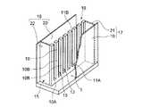
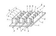
図1、図2は、請求項1、請求項6、請求項7、請求項8の発明に対応する第1の実施例の熱交換器を示すものである。なお図1においては、熱交換器の一部(後述する第1の側壁板19の一部)を切欠いた状態で示している。 1 and 2 show a heat exchanger according to a first embodiment corresponding to the inventions of
なお図1、図2に示す実施例の熱交換器においては、櫛型放熱ユニット10として、図3、図4に示したものを用いている。すなわち放熱ユニット10は、基本的には、比較的厚い金属板を、その板面と平行な面で切った断面の形状として、直線状に連続する基辺部分10Aから、複数の長板部分10Bが、所定の間隔を置いて相互に平行(基辺部分10Aに対し垂直)に並ぶように一体に立設して、いわゆる櫛型の形状とし、その隣り合う長板部分10Bの間の空隙を冷却用流体通路13としたものであり、図3、図4の例では、前記各長板部分10Bの断面形状として、細長い長方形をなすものを用いている。 In the heat exchanger of the embodiment shown in FIGS. 1 and 2, the comb-type
なお櫛型放熱ユニット10を構成する金属材としては、アルミニウムや、銅、それらの合金などの熱伝導性の良好な金属を用いれば良い。またこのような櫛型放熱ユニット10を製造するための手段は、基本的には特に限定されず、例えば厚板に切削加工を施して長板部分10Bを削り出しても良いが、コスト面からは押出加工を適用することが望ましい。すなわち、図7に示しているように、最終的に得るべき櫛型放熱ユニット10を複数枚重ねた形状の金属ブロック12、すなわち放熱ユニット10の各長板部分10Bの間の空隙(冷却流体用通路)13に対応する平行な複数の溝部12Aを有する金属ブロック12を、押出加工によって製造し、その金属ブロック12を、例えば図7中の破線Pで示すようにスライスすることによって、1つの押出金属ブロック12から多数の放熱ユニット10を得ることができる。但し、1つの押出金属ブロックを、スライスせずにそのまま1つの放熱ユニットとしても良いことはもちろんである。また、冷却用流体通路13の幅が狭い櫛型放熱ユニットを得たい場合には、後に改めて図8を参照して説明するように、押出加工の後、矢印C、C’で示すように両側から圧縮してもよい。 In addition, as a metal material which comprises the comb-type
図1、図2において、ベースプレート1は、図示しない半導体素子、集積回路、CPU等の発熱部品が裏面側に熱的に接続されるものであり、アルミニウム、銅、あるいはそれらの合金などの熱伝導性が良好な材料によって、例えば方形厚板状に作られており、このベースプレート1の表側には、前記櫛型放熱ユニット10が立設されている。すなわち、各冷却用流体通路13がベースプレート1の表面とほぼ平行となるように、すなわち櫛型放熱ユニット10の長板部分10Bがベースプレート1の表面に対しほぼ垂直となるように、ベースプレート1上に立設されている。そしてこのような櫛型放熱ユニット10における基辺部分10Aが、ベースプレート1の板面に熱的に接続された状態で固定されている。さらにベースプレート1の上側の空間の手前側の部分が、冷却用流体が流入する入口部15とされ、奥の部分が冷却用流体が流出する出口部16とされている。 In FIG. 1 and FIG. 2, a
さらにベースプレート1上には、冷却用流体、例えば空気が流入する入口部15とその冷却用空気が流出する出口部16との間で、その冷却用空気の流れをベースプレート1の板面と平行な面内において誘導するための流体誘導手段として、第1の隔壁17および第2の隔壁18とが設けられている。 Further, on the
前記第1の隔壁17は、櫛型放熱ユニット10における各冷却用流体通路13の一方の開口端が並ぶ側(以下これを「一方の開口面11Aの側」と記す)の空間において、前記入口部15および櫛型放熱ユニット10の各流体通路13を除くほかはベースプレート1の板面と平行な面内での冷却用空気の流出および冷却用流体以外の流体の流入を阻止するためのもの、言い換えれば、入口部15および各流体通路13を除き、ベースプレート1の板面と平行な面内で隣接する部分と仕切るためのものである。また第2の隔壁18は、櫛型放熱ユニット10における各冷却用流体通路13の他方の開口端が並ぶ側(以下これを「他方の開口面11Bの側」と記す)の空間において、櫛型放熱ユニット10の各流体通路13及び前記出口部16を除くほかはベースプレート1の板面と平行な面内での冷却用空気の流出および冷却用流体以外の流体の流入を阻止するためのもの、言い換えれば、出口部16と各流体通路13を除き、ベースプレート1の板面と平行な面内で隣接する部分と仕切るためのものである。ここで、櫛型放熱ユニット10における開口面11A、11Bとは、上述のところから理解できるように、櫛型放熱ユニット10において複数の長板部分10Bが並ぶ面の両側を意味している。 The
前記第1の隔壁17は、櫛型放熱ユニット10から離れてその一方の開口面11Aにほぼ平行となるように設けた第1の側壁板19と、櫛型放熱ユニット10の一方の開口面11Aの側において出口部16の側の櫛型放熱ユニット端部と第1の側壁板19とを連接させる第1の邪魔板21とによって構成されている。また前記第2の隔壁18は、櫛型放熱ユニット10から離れてその一方の開口面11Bにほぼ平行となるように設けた第2の側壁板20と、櫛型放熱ユニット10の他方の開口面11Bの側において入口部15の側の櫛型放熱ユニット端部と第2の側壁板20とを連接させる第2の邪魔板22とによって構成されている。 The
ここで、第1の隔壁17、第2の隔壁18をそれぞれ構成する各側壁板19,20および邪魔板21,22の材質は特に限定されるものではなく、加工性あるいは接合性等を考慮して適宜の材料を用いれば良く、ベースプレート1や櫛型放熱ユニット10と同様なアルミニウムや銅、それらの合金等の熱伝導性の良好な合金を用いても良いことはもちろんである。 Here, the materials of the
なお図1、図2に示す例においては、第1および第2の邪魔板21、22を、櫛型放熱ユニット10の各開口面11A、11Bに対してほぼ平行となるように設けているが、これに限るものではなく、これらの邪魔板21、22を開口面11A、11Bに対してある角度をなすように設けても良いことはもちろんである。また第1の側壁板19と第1の邪魔板21とは、別部材として作られている必要はなく、場合によっては一体物として1枚の板で作っても良く、また第2の側壁板20と第2の邪魔板22も、同様に一体物として1枚の板で作っても良い。 In the example shown in FIGS. 1 and 2, the first and
ここで、櫛型放熱ユニット10をベースプレート1に熱的に接続した状態で固定するための手段は特に限定されないが、例えばロウ付け、ハンダ付け、接着、圧入、あるいは機械的カシメ等によって結合しても良く、さらにはこれらを併用しても良い。これらのうちでも、熱的接合の点からはロウ付けを適用することが最も好ましい。またベースプレート1上に櫛型放熱ユニット10を圧入や機械的カシメにより固定する場合、熱伝導グリスなどを併用しても良いことはもちろんである。 Here, the means for fixing the comb-shaped
以上のような図1、図2に示される第1の実施例の熱交換器における使用時の状況、特に冷却用流体として空気を用いた場合の空気の流れ(空気流)とそれによる放熱状況について次に説明する。 1 and FIG. 2 as described above, the situation at the time of use in the heat exchanger of the first embodiment, particularly the air flow (air flow) when air is used as the cooling fluid and the heat dissipation situation by the air flow Will be described next.
例えば図示しないファン等により送られてきた高速の空気流は、入口部15から櫛型放熱ユニット10の一方の開口面11Aと第1の側壁板19との間の略直方体状の空間に送り込まれる。この空間において高速の空気流は開口面11Aおよび第1の側壁板19の板面に沿って図2の奥へ流れ、最奥部において第1の邪魔板21によってその流れが阻止されて流れの方向が転回され、櫛型放熱ユニット10の各冷却用流体通路13に開口面11Aの側から入り、開口面11Bの側へ送り出され、開口面11Bと第2の側壁板20との間の空間で合流して、出口部16から外部へ放出される。この過程で、空気流は、前述のように入口部15から流入した後、奥の第1の邪魔板19によりその方向を転回させられて多数の流体通路13に分散して流入することにより、その速度が減じられ、低速の空気流として多数の流体通路13をほぼ均一に通過することになる。そしてその低速の空気流が各流体通路13を通過する間に、櫛型放熱ユニット10における各流体通路13の両側の長板部分10Bの表面から熱を奪い、温度上昇して開口面11B側から出口部16に送り出されることになる。このように、高速で送り込まれた空気流は、櫛型放熱ユニット10における多数の冷却用流体通路13内を、低速の空気流としてほぼ均一に分散して通過することにより、優れた放熱性能が得られる。 For example, a high-speed air flow sent by a fan or the like (not shown) is sent from the
ここで、既に述べた特許文献1に示されている熱交換器の各構造例のうち、この発明の第1の実施例に対応する構造例を図17および図18に示し、その図17、図18に示される従来の提案の熱交換器と図1、図2に示すこの発明の第1の実施例の熱交換器とを対比する。なお特許文献1においては、「板状フィン」、「フィン部」、「フィン群」については、次のように定義されている。すなわち、個々の板状フィン2は、図17および図18においてベースプレート1の板面に立設されたものであり、フィン部4とは、図17および図18に示すように板状フィン2が縦方向に複数個並んで一列に配置されたものの全体を言う。またフィン群とは、複数のフィン部4の全体、すなわち例えば図22に示すように二つのフィン部4がハの字形に配置されて形成されたものとしている。 Here, among the structural examples of the heat exchanger shown in
図17および図18に示すような特許文献1で述べられている熱交換器では、多数の板状フィン2を所定の角度でベースプレート1上に並列に配置することによりフィン部4を構成しており、隣り合う板状フィン2の間を冷却風が通過するようになっている。このような構造では、取扱う板状フィン2の個数が極めて多くなり、部品製造コストが増大すると同時に、ベースプレート1上に板状フィン2を配置する作業に大きなコストがかかってしまう。 In the heat exchanger described in
これに対し、この発明の熱交換器、特に図1、図2に示す実施例の熱交換器では、特許文献1でいう多数の板状フィン、すなわち図17、図18に示されている熱交換器における多数の板状フィン2の全体が櫛型放熱ユニット10に置き換えられている。このため、取り扱う部材の個数が特許文献1の熱交換器の場合と比べて格段に少なくなり、そのため熱交換器を少ない部品点数で構成することができるようになり、部品製造コストと接合作業のコストを大幅に低減することが可能となったのである。 On the other hand, in the heat exchanger of the present invention, particularly the heat exchanger of the embodiment shown in FIG. 1 and FIG. 2, a large number of plate-like fins referred to in
図10、図11には、請求項1、請求項6、請求項9の各発明に対応する第2の実施例による熱交換器を示す。なお図10、図11については、図1、図2に示される要素と同一の要素については同一の符号を付し、その詳細な説明は省略する。 10 and 11 show a heat exchanger according to a second embodiment corresponding to each of the inventions of
図10、図11において、ベースプレート1上には前記同様な櫛型放熱ユニット10が立設されており、流体誘導手段としての第1の隔壁17は第3の側壁板23により、また第2の隔壁18は第4の側壁板24によって構成されている。すなわち、櫛型放熱ユニットの一方の開口面11Aの側に第3の側壁板23が立設され、櫛型放熱ユニット10の他方の開口面11Bの側に第4の側壁板24が立設されており、かつ第3の側壁板23は、その板面と櫛型放熱ユニット10の一方の開口面11Aとの間隔が、入口部15から出口部16に向けて漸次狭くなって、櫛型放熱ユニット10の出口部16の側の端部で両者が接するように配置され、また第4の側壁板24は、その板面と櫛型放熱ユニット10の他方の開口面11Bとの間隔が出口部16の側から入口部15の側に向けて漸次狭くなって、入口部櫛型放熱ユニット10における入口部15の側の端部で両者が接するように配置されている。 10 and 11, a comb-type
このような図10、図11に示される第2の実施例は、前記第1の実施例において櫛型放熱ユニット10の一方の開口面11Aに対してほぼ平行に設けた1枚の側壁板19と、その開口面11Aに対しほぼ垂直に設けた1枚の邪魔板21の代わりに、1枚の側壁板23をその開口面11Aに対して斜めに設け、かつ第1の実施例において櫛型放熱ユニット10の他方の開口面11Bに対してほぼ平行に設けた1枚の側壁板20と、その開口面11Aに対してほぼ垂直に設けた1枚の邪魔板22の代りに、1枚の側壁板24を開口面11Bに対して斜めに設けることにより、第1の実施例の場合と同様の機能を果たさせたものということができる。 10 and FIG. 11, the second embodiment shown in FIG. 10 and FIG. 11 is a single
なお付言するならば、図10および図11では、入口部15から出口部16に向かう方向に対して、櫛型放熱ユニット10の開口面11A、11Bが平行となるように配置されていて、側壁板23、24がある角度をなして配置されているように描かれているが、実際には、側壁板23、24が入口部15から出口部16に向かう方向に対して平行に配置されていて、櫛型放熱ユニット10の開口面11A、11Bがある角度をなすように配置されていても良い。あるいはまた、櫛型放熱ユニット10の開口面11A、11Bおよび側壁板23、24の双方が、入口部15から出口部16に向かう方向に対してある角度をなすように配置されていても良いことはもちろんである。 In addition, in addition, in FIGS. 10 and 11, the opening surfaces 11 </ b> A and 11 </ b> B of the comb-shaped
なおこの実施例において、第3および第4の側壁板23、24の素材としては、前述の第1の実施例における第1、第2の側壁板19、20について述べたところと同様の材料を用いることができ、またその第3、第4の側壁板23、24をベースプレート1の板面に固定する方法としても、既に述べた方法と同様の方法を適用することができる。 In this embodiment, the materials for the third and fourth
このような図10、図11に示される第2の実施例の熱交換器を実際に使用する際の冷却用空気の流れ(空気流)は、基本的には図1、図2に示した第1の実施例の場合とほぼ同様であるが、ここで改めて簡単に説明する。 The flow of cooling air (air flow) when actually using the heat exchanger of the second embodiment shown in FIGS. 10 and 11 is basically shown in FIGS. Although it is almost the same as the case of the first embodiment, it will be briefly described here again.
熱交換器の外部から入口部15に送り込まれる高速の空気流は、その入口部15から第3の側壁板23と櫛型放熱ユニット10の一方の開口面11Aとの間の空間に流入し、その奥に送り送り込まれる。ここで、櫛型放熱ユニット10の一方の開口面11Aの側では、開口面11Aと第3の側壁板23の板面との間隔が、入口部15の側から奥に向かって漸次狭くなって最奥の出口部16の側におけるフィン端部では櫛型放熱ユニット10と第3の側壁板23とが接するように配置されているため、上述の高速の空気流は方向を転回して入口部15に戻る方向に流れ、その間に櫛型放熱ユニット10における長板部分10Bの間の多数の空隙(冷却用流体通路)13に分散されることにより、速度が減じられた状態(低速の空気流となった状態)でほぼ均一に各流体通路13に流れ込み、各流体通路13を通過して、櫛型放熱ユニット10の他方の開口面11Bの側に出る。開口面11Bの側では、開口面11Bと第4の側壁板24とが入口部15の側におけるフィン端部で接しており、開口面11Bと第4の側壁板24との間隔が入口部15の側から奥に向かって漸次広くなっているため、櫛型放熱ユニット10の各流体通路13を通過した空気流は出口部16へと誘導され、出口部16から熱交換器外に流出される。 A high-speed air flow sent from the outside of the heat exchanger to the
ここで、特許文献1に示されている熱交換器の各構造例のうち、この発明の第2の実施例に対応する構造例を図19に示し、その図19の熱交換器とこの発明の第2の実施例である図10、図11の熱交換器とを対比する。 Here, among the structural examples of the heat exchanger shown in
図19に示した特許文献1で述べられている熱交換器では、ベースプレート1上に、多数の板状フィン2を所定の角度で並列状に配置することによりフィン部4を構成している。このような構造では、取り扱う板状フィン2の個数が極めて多くなり、製造コストが増大するとともに、ベースプレート1上に多数の板状フィン2を配置する作業に大きなコストが必要となる。 In the heat exchanger described in
これに対し、この発明の第2の実施例の熱交換器においては、前述の第1の実施例の場合と同様に、特許文献1でいう板状フィン2が櫛型放熱ユニット10に置き換えられ、特許文献1でいうフィン部4が櫛型放熱ユニット10として一体物の一部品となっている。このため、取り扱う部材の個数は特許文献1の場合に比べて格段に少なく、熱交換器を少ない部品点数で構成することができるようになり、部品製造コストと接合作業のコストを大幅に低減できるのである。 On the other hand, in the heat exchanger according to the second embodiment of the present invention, the plate-
図12、図13には、請求項1および請求項10に対応するこの発明の第3の実施例の熱交換器を示す。 FIGS. 12 and 13 show a heat exchanger according to a third embodiment of the present invention corresponding to
図12、図13に示す第3の実施例の熱交換器においては、ベースプレート1上に、2個の櫛型放熱ユニット10−1、10−2が立設されている。そしてこれらの2個の櫛型放熱ユニット10−1、10−2は、その間隔(開口面間の間隔)が、入口部15から出口部16に向かって漸次狭くなり、出口部16の側でユニット端部が相互に接するように位置決めされている。 In the heat exchanger of the third embodiment shown in FIGS. 12 and 13, two comb-type heat radiation units 10-1 and 10-2 are erected on the
なおここで使用した櫛型放熱ユニット10−1、10−2の各冷却用流体流路13は、放熱ユニット10−1、10−2の開口面11A、11Bに対して90°未満の角度で傾斜しており、このように傾斜させることにより、圧力損失を低くして冷却風が流れやすくなるようにすることができる。 In addition, each cooling
上述のような図12、図13に示す第3の実施例の熱交換器においては、前述の第1、第2の実施例における第1の隔壁17(具体的には、第1の実施例においては第1の側壁板19および第1の邪魔板21に相当し、第2の実施例では第3の側壁板23に相当)、および第2の隔壁18(具体的には、第1の実施例においては第2側壁板20および第2の邪魔板22に相当し、第2の実施例では第4の側壁板24に相当)を特には設けていないが、これは、次に述べる空気流の流れについての説明から理解できるように、2個の櫛型放熱ユニット10−1、10−2の配置形態そのものが、流体誘導手段となっているためである。 In the heat exchanger of the third embodiment shown in FIGS. 12 and 13 as described above, the first partition wall 17 (specifically, the first embodiment) in the first and second embodiments described above. 2 corresponds to the first
そこで、この第3の実施例の熱交換器における冷却用空気(冷却風)の流れについて説明する。 Therefore, the flow of cooling air (cooling air) in the heat exchanger of the third embodiment will be described.
熱交換器には、外部から2枚の櫛型放熱ユニット10−1、10−2の手前側の端部の間に開口されている入口部15に高速の空気流が送り込まれ、その高速の空気流は、2枚の櫛型放熱ユニット10−1、10−2におけるそれぞれ一方の開口面11Aの間の空間に流れ込む。ここで、2枚の櫛型放熱ユニット10−1、10−2は、その間隔が入口部15の側から奥に向かって漸次狭くなって、最奥の出口部16の側におけるユニット端部で両者が接するように配置されているため、上述した高速の空気流は左右に方向を転回し、2枚の櫛型放熱ユニット10−1、10−2における多数の空隙(流体通路13)へと向かう。そして前述の第1、第2の実施例の場合と同様に、多数の空隙に分散されることにより速度を減じて、低速の空気流として、ほぼ均一に多数の空隙(流体通路13)に流入してその流体通路13を通過し、その間、櫛型放熱ユニット10における各長板部分10Bの表面から熱が奪われ、さらに各流体通路13を出た空気流は、櫛型放熱ユニット10−1、10−2のそれぞれ他方の開口面11Bから出口部16に至る。このように、図12、図13に示す第3の実施例の場合は、特に側壁板や邪魔板からなる隔壁を設けていないにもかかわらず、2枚の櫛型放熱ユニット10−1、10−2の配置態様それ自体によって、空気流を入口部15から櫛型放熱ユニット10−1、10−2に導くとともに、その櫛型放熱ユニット10−1、10−2の多数の流体通路13(各櫛型放熱ユニット10における長板部分10Bの相互間の空隙)を実質的に均一に通過させ、出口部16に導くことができるのである。 A high-speed air flow is sent to the heat exchanger from the outside to the
なお図12、図13に示す例では、出口部16の側でユニット端部が相互に直接的に接するように位置決めされていることとしたが、出口部16の側においてユニット端部は、要は相互に実質的に接していれば良いのであって、例えば図示しない隔壁状の小部品を介して間接的に接していても良く、また多数の櫛型放熱ユニット内の空隙(冷却用流体通路13)を流れる空気流に影響を与えない程度の小さい隙間であれば、ユニット端部が相互に近接してその間に小さい隙間が存在していても構わない。 In the examples shown in FIGS. 12 and 13, the unit ends are positioned so as to be in direct contact with each other on the
ここで特許文献1に示されている熱交換器の各構造例のうち、この発明の第3の実施例に対応する構造例を図20に示し、その図20の熱交換器と図12、図13に示すこの発明の第3の実施例の熱交換器とを対比する。 Here, among the structural examples of the heat exchanger shown in
図20に示した特許文献1で述べられている熱交換器では、ベースプレート1上に多数の板状フィン2を所定の角度で並列状に配置することにより一つのフィン部4を構成し、そのフィン部4を平面的に見てハの字状に配置することによりフィン群を構成している。 In the heat exchanger described in
このような構成では、取扱う板状フィン2の個数が極めて多くなって製造コストが増大するとともに、ベースプレート1上に多数の板状フィン2を配置する作業に大きなコストを要することとなる。 In such a configuration, the number of the plate-
これに対し、この発明の第3の実施例の熱交換器では、特許文献1でいうところのそれぞれ複数の板状フィン2を含む二つのフィン部4が、それぞれ櫛型放熱ユニット10−1、10−2として一体物の一部品となっている。このため、取り扱う部材の個数が特許文献1の場合に比べて格段に少なく、熱交換器を少ない部品点数で構成することができるようになり、部品製造コストと接合作業のコストを大幅に低減できるのである。 On the other hand, in the heat exchanger according to the third embodiment of the present invention, the two
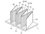
また一方、この発明の熱交換器は、図1、図2、図10〜図13に示した各実施例における配置構造を横方向(入口部15から出口部16に向かう方向に対し直交する方向)または縦方向(入口部15から出口部16に向かう方向)に複数回繰り返して構成することも可能であり、その例を図14〜図16に示し、さらにこれらの例に対応する特許文献1に示されている構造例を図21、図22に示す。これらについて次に説明する。 On the other hand, in the heat exchanger of the present invention, the arrangement structure in each embodiment shown in FIG. 1, FIG. 2, FIG. ) Or a plurality of times in the vertical direction (the direction from the
図14には、図1および図2に示した第1の実施例における配置構造を横方向に複数繰り返して構成したこの発明の第4の実施例を示し、これに対応する従来の前記提案の熱交換器の構造例を図21に示す。 FIG. 14 shows a fourth embodiment of the present invention in which the arrangement structure in the first embodiment shown in FIGS. 1 and 2 is repeated a plurality of times in the horizontal direction. An example of the structure of the heat exchanger is shown in FIG.
また図15には、図10および図11に示した第2の実施例における配置構造を横方向に複数繰り返して構成したこの発明の第5の実施例を示す。 FIG. 15 shows a fifth embodiment of the present invention in which the arrangement structure in the second embodiment shown in FIGS. 10 and 11 is repeated a plurality of times in the horizontal direction.
さらに図16には、図12および図13に示した第3の実施例における配置構造を横方向に複数繰り返して構成したこの発明の第6の実施例を示し、これに対応する従来の前記提案の熱交換器の構造例を図22に示す。 Further, FIG. 16 shows a sixth embodiment of the present invention in which the arrangement structure in the third embodiment shown in FIGS. 12 and 13 is repeated a plurality of times in the horizontal direction, and the conventional proposal corresponding thereto is shown. An example of the structure of the heat exchanger is shown in FIG.
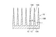
ここで、以上の図1、図2、図9〜図16に示した各実施例では、櫛型放熱ユニットとして、図3、図4に示した基本的な形状を有するものを用いているものとして示したが、図5、図6のいずれかの形状を有するものを用いることもできる。 Here, in each of the embodiments shown in FIGS. 1, 2, and 9 to 16, the comb-shaped heat radiation unit having the basic shape shown in FIGS. 3 and 4 is used. However, it is also possible to use one having the shape of either FIG. 5 or FIG.
すなわち図5に示される櫛型放熱ユニット10は、各長板部分10Bの厚み(1枚の放熱ユニット10内において複数の長板部分10Bが並ぶ方向の各長板部分の幅、と言い換えることができる)tが、基辺部分10Aに近い側から先端部(突出端部)に向かって漸減するような形状としたものである。このような櫛型放熱ユニット10においては、各長板部分10Bの断面積が、基辺部分10Aの側から先端部へ向かって漸減し、同時に隣り合う長板部分10Bの間隔、すなわち冷却用流体通路13の幅wが、基辺部分10Aの側から先端部に向かって次第に大きくなることになる。 That is, the comb-shaped
ここで、放熱ユニット10をベースプレートに熱的に接続した状態では、ベースプレートからの熱は、放熱ユニット10の基辺部分10Aを経て、各長辺部分10Bにおいて冷却用流体に放出されることになり、したがって各長辺部分10Bにおいては、基辺部分10Aに近い側では熱流密度が高く、先端部側では熱流密度が小さくなる。そして図5に示した放熱ユニット10の場合は、各長板部分10Bにおける熱流密度が高い側(基辺部分10Aに近い側)ではその断面積が大きくなって熱流密度を緩和することができる一方、熱流密度が低い側(先端部側)では冷却用流体通路の幅wが大きくなり、その側で冷却用流体の流れに対する抵抗が小さくなって、冷却用流体の流れが良くなり、これらの結果、全体としてベースプレートから冷却用流体への放熱を効率的に行なうことができる。 Here, in a state in which the
一方、図6に示される櫛型放熱ユニット10は、各長板部分10Bの側面(冷却用流体通路13を挟む側の表面)10D、10Eに鋸歯状の凹凸、すなわちいわゆるセレーションを形成したものである。このように長辺部分10Bにセレーションを形成した放熱ユニット10を用いた場合、冷却用流体通路13を通る冷却用流体と長板部分10Bの表面との接触面積が大きくなり、そのため放熱ユニットから冷却用流体への放熱効率を高めることができる。 On the other hand, the comb-shaped
なお図5に示す放熱ユニット、あるいは図6に示す放熱ユニットも、図3、図4に示す放熱ユニットの場合について既に説明したと同様に、押出加工によって容易に低コストで製造することができる。但し、図6に示すようなセレーションを有する放熱ユニットを製造するにあたっては、押出加工後に改めて切削加工等の機械加工によってセレーションを刻設しても良い。 The heat dissipation unit shown in FIG. 5 or the heat dissipation unit shown in FIG. 6 can also be easily manufactured at low cost by extrusion, as already described in the case of the heat dissipation unit shown in FIGS. However, when manufacturing a heat dissipation unit having serrations as shown in FIG. 6, serrations may be engraved again by machining such as cutting after extrusion.
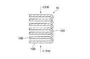
さらにこの発明の熱交換器においては、櫛型放熱ユニット10として、図8に示すように、基辺部分10Aの端面(ベースプレートに接する側の面)10Fに、比較的浅いU字形状を長板部分10Bのピッチと同ピッチで繰返した形状の凹凸を付与したものを用いることができる。この図8に示すような放熱ユニットは、次に述べるように、押出加工によって得られた原形状の放熱ユニットにさらに圧縮加工を施して、冷却用流体通路を狭める場合に好適である。 Further, in the heat exchanger according to the present invention, as a comb-type
すなわち、押出加工によって例えば図8に示すような放熱ユニット形状を作製した後、図9の矢印C、C’で示すように、複数の長板部分10Bが並ぶ方向の両側から圧縮することによって、隣り合う長板部分10Bの間の空隙の間隔(冷却用流体通路13の幅)wを容易に小さくすることができる。したがってこの場合は、冷却用流体通路の幅が狭い放熱ユニットを、容易に得ることが可能となるのである。 That is, after producing a heat radiation unit shape as shown in FIG. 8 by extrusion, for example, as shown by arrows C and C ′ in FIG. 9, by compressing from both sides in the direction in which a plurality of
なおこの発明の熱交換器に使用される櫛型放熱ユニットの各部分の具体的な寸法や、長板部分の数等は特に限られるものではない。 In addition, the specific dimension of each part of the comb-type heat radiation unit used in the heat exchanger of the present invention, the number of long plate parts, and the like are not particularly limited.
なおこのような熱交換器を半導体素子等の電子部品や電気部品などの放熱に使用するにあたっては、従来からある熱交換器の放熱フィンの場合と同様に、櫛型放熱ユニットの部分に空気やLLC(ロングライフクーラント)等の冷却用流体を確実に流してやる必要があることは言うまでもない。そのためには、重力で空気を流す自然空冷の場合を除き、空気等の冷却用流体を強制的に櫛型放熱ユニットに流すためのファンやポンプなどの冷却用流体の駆動源が冷却用流体の流れの上流もしくは下流に配置されるのが通常である。 In addition, when using such a heat exchanger for heat dissipation of electronic parts such as semiconductor elements and electrical parts, as in the case of heat dissipation fins of conventional heat exchangers, air or Needless to say, it is necessary to flow a cooling fluid such as LLC (Long Life Coolant) reliably. For this purpose, the cooling fluid drive source such as a fan or a pump for forcing a cooling fluid such as air to flow into the comb-type heat dissipation unit is used as a cooling fluid, except in the case of natural air cooling where air flows by gravity. It is usually located upstream or downstream of the flow.
そして、櫛型放熱ユニットを有する熱交換器の部分に確実に冷却用流体が流れるようにするために、熱交換器の外部における冷却用流体の流れる経路がダクト等によって仕切られていることが好ましい。ファンやポンプが冷却用流体の流れの上流に配置される場合には、冷却用流体が経路外に漏れ出すことのないように、またファンやポンプが冷却用流体の流れの下流に配置される場合には、冷却用流体以外の流体が経路外から混入したりすることのないように形成されていることが好ましい。それらのダクト等が配置される場所としては、熱交換器の上流側のみ、下流側のみ、上流と下流の両方、のいずれでもかまわない。 In order to ensure that the cooling fluid flows through the portion of the heat exchanger having the comb-type heat radiation unit, it is preferable that the flow path of the cooling fluid outside the heat exchanger is partitioned by a duct or the like. . When the fan or pump is arranged upstream of the cooling fluid flow, the cooling fluid is not leaked out of the path, and the fan or pump is arranged downstream of the cooling fluid flow. In such a case, it is preferable that the fluid other than the cooling fluid is not mixed from outside the path. The place where these ducts and the like are arranged may be only on the upstream side of the heat exchanger, only on the downstream side, or on both the upstream and downstream sides.
また櫛型放熱ユニットを有する熱交換器の部分についても同様に、その櫛型放熱ユニットを有する熱交換器を囲うようにダクト等が配置されているのが好ましい。その場合、少なくとも櫛型放熱ユニットの上方の開放部分が覆われている必要があり、またその具体的構造として、その覆いが櫛型放熱ユニットの上端と接合されて一体になっている構造でもかまわない。またその覆いは、前述の熱交換器の上流側のみ、下流側のみ、上流と下流の両方、のいずれかに配置するダクト等と別部品であっても、一体であってもかまわない。 Similarly, it is preferable that a duct or the like is arranged so as to surround the heat exchanger having the comb-shaped heat radiation unit in the portion of the heat exchanger having the comb-shaped heat radiation unit. In that case, at least the open part above the comb-type heat dissipation unit must be covered, and as its specific structure, the cover may be joined to the upper end of the comb-type heat dissipation unit and integrated. Absent. Further, the cover may be a separate part or a single part from a duct or the like disposed only on the upstream side, only on the downstream side, or on both the upstream and downstream sides of the heat exchanger.
なお一般に放熱フィンの部分(この発明の場合は櫛型放熱ユニットの部分)に確実に冷却用流体が流れるようにすること自体は、特にこの発明の熱交換器に限って必要な事柄ではなく、従来からある熱交換器にも当てはまるものである。 In general, ensuring that the cooling fluid flows through the portion of the radiating fin (in the case of the present invention, the portion of the comb-shaped heat radiating unit) is not a necessary matter only in the heat exchanger of the present invention. This also applies to conventional heat exchangers.
1 ベースプレート
10 櫛型放熱ユニット
10−1 櫛型放熱ユニット
10−2 櫛型放熱ユニット
10A 基辺部分
10B 長板部分
11A、11B 櫛型放熱ユニットの開口面
13 冷却用流体通路(空隙)
15 入口部
16 出口部
17 第1の隔壁
18 第2の隔壁
19 第1の側壁板
20 第2の側壁板
21 第1の邪魔板
22 第2の邪魔板
23 第3の側壁板
24 第4の側壁板DESCRIPTION OF
DESCRIPTION OF
Claims (12)
Translated fromJapanese冷却用流体が流入する入口部と、冷却用流体が流出する出口部とを有し、かつ前記放熱ユニットとして、基辺部分から多数の長板部分が櫛歯状に平行して一体に立設されて、その隣り合う長板部分の間の空隙を冷却用流体通路としたものが用いられ、その放熱ユニットは、その冷却用流体通路がベースプレートに対してほぼ平行となるように、かつ前記基辺部分がベースプレートに熱的に接続されるようにベースプレート上に立設された構成とされ、
さらに前記ベースプレート上には、前記入口部から流入した冷却用流体の流れをベースプレートの板面と平行な面内で誘導するための流体誘導手段が設けられており、しかもその流体誘導手段は、冷却用流体を前記入口部から前記放熱ユニットにおける板面間の各冷却用流体通路の一方の開口端に導き、その冷却用流体が前記放熱ユニットにおける各冷却用流体通路を通過してその他方の開口端から前記出口部に導かれるように、冷却用流体の流れを誘導する構成とされていることを特徴とする、櫛型放熱ユニットを備えた熱交換器。In a heat exchanger in which a heat dissipating unit for conducting heat transfer to a cooling fluid is provided on a base plate to which heat generating components are thermally connected,
As the heat dissipation unit, a large number of long plate portions are erected integrally in parallel with a comb-teeth shape from the base portion, having an inlet portion into which the cooling fluid flows in and an outlet portion through which the cooling fluid flows out. Then, a cooling fluid passage is used as a gap between the adjacent long plate portions, and the heat dissipation unit has the base so that the cooling fluid passage is substantially parallel to the base plate. It is configured to stand on the base plate so that the side portion is thermally connected to the base plate,
Furthermore, fluid guiding means for guiding the flow of the cooling fluid flowing from the inlet portion in a plane parallel to the plate surface of the base plate is provided on the base plate, and the fluid guiding means is a cooling mechanism. The cooling fluid is led from the inlet portion to one opening end of each cooling fluid passage between the plate surfaces of the heat radiating unit, and the cooling fluid passes through each cooling fluid passage in the heat radiating unit and opens to the other side. A heat exchanger provided with a comb-shaped heat dissipation unit, wherein the flow of cooling fluid is guided so as to be led from the end to the outlet portion.
前記放熱ユニットは、各長板部分の厚みが基辺部分に近い側から先端部に向って漸減するように作られていることを特徴とする、櫛型放熱ユニットを備えた熱交換器。In the heat exchanger provided with the comb-type heat radiation unit according to claim 1,
The heat radiating unit is formed so that the thickness of each long plate portion gradually decreases from the side close to the base portion toward the distal end portion.
前記放熱ユニットは、各長板部分における前記冷却用流体通路を挟む側の表面に鋸歯状の凹凸が付されたものであることを特徴とする、櫛型放熱ユニットを備えた熱交換器。In the heat exchanger provided with the comb-type heat radiation unit according to claim 1,
The heat radiating unit is a heat exchanger provided with a comb-shaped radiating unit, wherein the surface of the long plate portion on the side sandwiching the cooling fluid passage is provided with serrated irregularities.
前記放熱ユニットは、その基辺部分におけるベースプレートに熱的に接続される側の面に、U字形状を繰返す凹凸形状が付されたものであることを特徴とする、櫛型放熱ユニットを備えた熱交換器。In the heat exchanger provided with the comb-type heat radiation unit according to claim 1,
The heat dissipating unit is provided with a comb heat dissipating unit, characterized in that a concave and convex shape that repeats a U-shape is attached to a surface of the base side portion that is thermally connected to the base plate. Heat exchanger.
前記放熱ユニットが、押出加工によって作られたものであることを特徴とする、櫛型放熱ユニットを備えた熱交換器。In the heat exchanger provided with the comb-type heat radiation unit according to claim 1,
A heat exchanger provided with a comb-shaped heat radiation unit, wherein the heat radiation unit is made by extrusion.
前記流体誘導手段が、前記冷却用流体を前記入口部から前記放熱ユニットにおける各冷却用流体通路の一方の開口端が並ぶ面にほぼ沿って流入させ、さらに放熱ユニットの各冷却用流体通路を実質的に均一に通過させて、前記放熱ユニットにおける各冷却用流体通路の他方の開口端が並ぶ側の面にほぼ沿って前記出口部に向け流れるように、冷却用流体の流れを誘導する構成としたことを特徴とする、櫛型放熱ユニットを備えた熱交換器。In the heat exchanger according to any one of claims 1 to 5,
The fluid guiding means causes the cooling fluid to flow from the inlet portion substantially along a surface along which one open ends of the cooling fluid passages in the heat radiating unit are arranged, and further each cooling fluid passage of the heat radiating unit is substantially provided. The flow of the cooling fluid is guided so as to flow toward the outlet portion substantially along the surface on the side where the other opening ends of the cooling fluid passages in the heat radiating unit are lined up uniformly. A heat exchanger provided with a comb-shaped heat dissipation unit.
前記流体誘導手段が、前記放熱ユニットにおける各冷却用流体通路の一方の開口端が並ぶ側の空間において、前記入口部および放熱ユニットの各冷却用流体通路を除くほかは、前記ベースプレートの板面と平行な面内での冷却用流体の流出および冷却用流体以外の流体の流入を防止するための第1の隔壁と、放熱ユニットにおける各冷却用流体通路の他方の開口端が並ぶ側の空間において、放熱ユニットの各冷却用流体通路及び前記出口部を除くほかは、ベースプレートの板面と平行な面内での冷却用流体の流出および冷却用流体以外の流体の流入を防止するための第2の隔壁、とからなることを特徴とする、櫛型放熱ユニットを備えた熱交換器。In the heat exchanger according to any one of claims 1 to 6,
In the space on the side where one open end of each cooling fluid passage in the heat radiating unit is lined up, the fluid guiding means, except for the inlet fluid passage and each cooling fluid passage in the heat radiating unit, In a space on the side where the first partition wall for preventing the outflow of the cooling fluid in the parallel plane and the inflow of the fluid other than the cooling fluid and the other opening end of each cooling fluid passage in the heat dissipation unit are arranged Except for the cooling fluid passages and the outlet portion of the heat radiating unit, a second for preventing the cooling fluid from flowing out and the fluid other than the cooling fluid from flowing in the plane parallel to the plate surface of the base plate. A heat exchanger equipped with a comb-shaped heat radiation unit.
Priority Applications (1)
| Application Number | Priority Date | Filing Date | Title |
|---|---|---|---|
| JP2009202618AJP2011054778A (en) | 2009-09-02 | 2009-09-02 | Heat exchanger using comb-type radiation unit |
Applications Claiming Priority (1)
| Application Number | Priority Date | Filing Date | Title |
|---|---|---|---|
| JP2009202618AJP2011054778A (en) | 2009-09-02 | 2009-09-02 | Heat exchanger using comb-type radiation unit |
Publications (1)
| Publication Number | Publication Date |
|---|---|
| JP2011054778Atrue JP2011054778A (en) | 2011-03-17 |
Family
ID=43943494
Family Applications (1)
| Application Number | Title | Priority Date | Filing Date |
|---|---|---|---|
| JP2009202618APendingJP2011054778A (en) | 2009-09-02 | 2009-09-02 | Heat exchanger using comb-type radiation unit |
Country Status (1)
| Country | Link |
|---|---|
| JP (1) | JP2011054778A (en) |
Cited By (5)
| Publication number | Priority date | Publication date | Assignee | Title |
|---|---|---|---|---|
| WO2015137009A1 (en)* | 2014-03-14 | 2015-09-17 | 富士電機株式会社 | Cooling device and semiconductor device having said cooling device |
| WO2016121584A1 (en)* | 2015-01-29 | 2016-08-04 | 八洋エンジニアリング株式会社 | Server rack and server cooling device |
| JP2016220317A (en)* | 2015-05-15 | 2016-12-22 | 富士電機株式会社 | Cooling structure of conductor connection part |
| JP2018523773A (en)* | 2015-07-16 | 2018-08-23 | エムエイチアイ ヴェスタス オフショア ウィンド エー/エス | Wind turbine tower cooling panel assembly and wind turbine tower |
| JP2022150714A (en)* | 2021-03-26 | 2022-10-07 | 本田技研工業株式会社 | Heat exchanger and manufacturing method therefor |
Citations (10)
| Publication number | Priority date | Publication date | Assignee | Title |
|---|---|---|---|---|
| JPS62257796A (en)* | 1986-05-02 | 1987-11-10 | 株式会社日立製作所 | Cooling device for electronic parts |
| JPS63138799A (en)* | 1986-11-28 | 1988-06-10 | インターナショナル・ビジネス・マシーンズ・コーポレーション | Cooling circuit module |
| JPH1062572A (en)* | 1996-08-21 | 1998-03-06 | Matsushita Electric Works Ltd | Heat exchanger |
| JPH11129046A (en)* | 1997-10-31 | 1999-05-18 | Nippon Alum Co Ltd | Plate fin type heat sink manufacture |
| JP2000349208A (en)* | 1999-06-03 | 2000-12-15 | Nippon Alum Co Ltd | Manufacture of high tongue-ratio heat sink |
| JP2001352025A (en)* | 2000-06-05 | 2001-12-21 | Toshiba Corp | Heating element cooling device |
| JP2002118211A (en)* | 2000-10-12 | 2002-04-19 | Mizutani Denki Kogyo Kk | Radiator of electronic component and manufacturing method of the radiator |
| JP2006286767A (en)* | 2005-03-31 | 2006-10-19 | Hitachi Ltd | Cooling jacket |
| JP2006295178A (en)* | 2005-04-11 | 2006-10-26 | Samsung Electronics Co Ltd | Heat sink device for electronic elements |
| JP2008205421A (en)* | 2006-07-26 | 2008-09-04 | Furukawa Sky Kk | Heat exchanger |
- 2009
- 2009-09-02JPJP2009202618Apatent/JP2011054778A/enactivePending
Patent Citations (10)
| Publication number | Priority date | Publication date | Assignee | Title |
|---|---|---|---|---|
| JPS62257796A (en)* | 1986-05-02 | 1987-11-10 | 株式会社日立製作所 | Cooling device for electronic parts |
| JPS63138799A (en)* | 1986-11-28 | 1988-06-10 | インターナショナル・ビジネス・マシーンズ・コーポレーション | Cooling circuit module |
| JPH1062572A (en)* | 1996-08-21 | 1998-03-06 | Matsushita Electric Works Ltd | Heat exchanger |
| JPH11129046A (en)* | 1997-10-31 | 1999-05-18 | Nippon Alum Co Ltd | Plate fin type heat sink manufacture |
| JP2000349208A (en)* | 1999-06-03 | 2000-12-15 | Nippon Alum Co Ltd | Manufacture of high tongue-ratio heat sink |
| JP2001352025A (en)* | 2000-06-05 | 2001-12-21 | Toshiba Corp | Heating element cooling device |
| JP2002118211A (en)* | 2000-10-12 | 2002-04-19 | Mizutani Denki Kogyo Kk | Radiator of electronic component and manufacturing method of the radiator |
| JP2006286767A (en)* | 2005-03-31 | 2006-10-19 | Hitachi Ltd | Cooling jacket |
| JP2006295178A (en)* | 2005-04-11 | 2006-10-26 | Samsung Electronics Co Ltd | Heat sink device for electronic elements |
| JP2008205421A (en)* | 2006-07-26 | 2008-09-04 | Furukawa Sky Kk | Heat exchanger |
Cited By (11)
| Publication number | Priority date | Publication date | Assignee | Title |
|---|---|---|---|---|
| WO2015137009A1 (en)* | 2014-03-14 | 2015-09-17 | 富士電機株式会社 | Cooling device and semiconductor device having said cooling device |
| CN105531819A (en)* | 2014-03-14 | 2016-04-27 | 富士电机株式会社 | Cooler and semiconductor device having same |
| JPWO2015137009A1 (en)* | 2014-03-14 | 2017-04-06 | 富士電機株式会社 | Cooler and semiconductor device having the cooler |
| US9653379B2 (en) | 2014-03-14 | 2017-05-16 | Fuji Electric Co., Ltd. | Cooler and semiconductor device having cooler |
| WO2016121584A1 (en)* | 2015-01-29 | 2016-08-04 | 八洋エンジニアリング株式会社 | Server rack and server cooling device |
| CN107407949A (en)* | 2015-01-29 | 2017-11-28 | 金尾英敏 | Server rack and server cooling device |
| JP2016220317A (en)* | 2015-05-15 | 2016-12-22 | 富士電機株式会社 | Cooling structure of conductor connection part |
| JP2018523773A (en)* | 2015-07-16 | 2018-08-23 | エムエイチアイ ヴェスタス オフショア ウィンド エー/エス | Wind turbine tower cooling panel assembly and wind turbine tower |
| JP2022150714A (en)* | 2021-03-26 | 2022-10-07 | 本田技研工業株式会社 | Heat exchanger and manufacturing method therefor |
| JP7229292B2 (en) | 2021-03-26 | 2023-02-27 | 本田技研工業株式会社 | Heat exchanger and manufacturing method thereof |
| US11774188B2 (en) | 2021-03-26 | 2023-10-03 | Honda Motor Co., Ltd. | Heat exchanger and manufacturing method thereof |
Similar Documents
| Publication | Publication Date | Title |
|---|---|---|
| US6422307B1 (en) | Ultra high fin density heat sink for electronics cooling | |
| JP4776032B2 (en) | Heat exchanger | |
| US7909087B2 (en) | Heat exchanger | |
| JP6349161B2 (en) | Liquid cooling system | |
| JP6738226B2 (en) | Cooling system | |
| US20120132400A1 (en) | Heat Sink | |
| JP2011054778A (en) | Heat exchanger using comb-type radiation unit | |
| JP5498143B2 (en) | Heat sink using bent louver-like heat dissipation unit | |
| JP2010118497A (en) | Heat exchanger equipped with fin with louvers | |
| JP5715352B2 (en) | heatsink | |
| JP2011003708A (en) | Heat exchanger using corrugated heat radiation unit | |
| JP5114324B2 (en) | Semiconductor device | |
| JP5839386B2 (en) | heatsink | |
| JP4485835B2 (en) | Radiator | |
| JP2012032121A (en) | Heat exchanger, air conditioner with the same, and method of manufacturing the same | |
| JP3992953B2 (en) | heatsink | |
| JP4410065B2 (en) | Cold plate for heat dissipation of electronic parts | |
| US20240414880A1 (en) | Cooling fin of a cooler, through which fluid can flow, for cooling power electronics | |
| JP6204048B2 (en) | Cooler | |
| JP5192448B2 (en) | Manufacturing method of grooved base plate for heat exchanger and grooved base plate for heat exchanger | |
| JP4585881B2 (en) | Heat sink for element cooling | |
| US20240381591A1 (en) | Cooling fin arrangement of a cooler, through which fluid can flow, for cooling power electronics | |
| JP5181879B2 (en) | Heat sink and heat dissipation system | |
| JP2011222996A (en) | Heat sink using multiple type heat dissipation unit | |
| JP4646219B2 (en) | heatsink |
Legal Events
| Date | Code | Title | Description |
|---|---|---|---|
| A621 | Written request for application examination | Effective date:20120821 Free format text:JAPANESE INTERMEDIATE CODE: A621 | |
| A977 | Report on retrieval | Effective date:20130528 Free format text:JAPANESE INTERMEDIATE CODE: A971007 | |
| A02 | Decision of refusal | Effective date:20131015 Free format text:JAPANESE INTERMEDIATE CODE: A02 |