JP2011053582A - Method for manufacturing display panel - Google Patents
Method for manufacturing display panelDownload PDFInfo
- Publication number
- JP2011053582A JP2011053582AJP2009204435AJP2009204435AJP2011053582AJP 2011053582 AJP2011053582 AJP 2011053582AJP 2009204435 AJP2009204435 AJP 2009204435AJP 2009204435 AJP2009204435 AJP 2009204435AJP 2011053582 AJP2011053582 AJP 2011053582A
- Authority
- JP
- Japan
- Prior art keywords
- panel
- display panel
- manufacturing
- substrate
- protective sheet
- Prior art date
- Legal status (The legal status is an assumption and is not a legal conclusion. Google has not performed a legal analysis and makes no representation as to the accuracy of the status listed.)
- Withdrawn
Links
- 238000004519manufacturing processMethods0.000titleclaimsabstractdescription70
- 238000000034methodMethods0.000titleclaimsabstractdescription55
- 239000000758substrateSubstances0.000claimsabstractdescription118
- 230000001681protective effectEffects0.000claimsabstractdescription91
- 239000012790adhesive layerSubstances0.000claimsdescription60
- 239000003566sealing materialSubstances0.000claimsdescription34
- 239000000463materialSubstances0.000claimsdescription22
- 239000000853adhesiveSubstances0.000claimsdescription17
- 230000001070adhesive effectEffects0.000claimsdescription17
- 230000015572biosynthetic processEffects0.000claimsdescription11
- 238000005530etchingMethods0.000claimsdescription11
- 230000001678irradiating effectEffects0.000claimsdescription6
- 230000002093peripheral effectEffects0.000claimsdescription6
- 239000010410layerSubstances0.000description70
- 238000005401electroluminescenceMethods0.000description68
- 230000008569processEffects0.000description35
- 229920005989resinPolymers0.000description15
- 239000011347resinSubstances0.000description15
- 238000007789sealingMethods0.000description15
- 239000011521glassSubstances0.000description8
- 239000002346layers by functionSubstances0.000description8
- 239000010409thin filmSubstances0.000description7
- 238000005192partitionMethods0.000description6
- 230000004888barrier functionEffects0.000description5
- 238000002347injectionMethods0.000description5
- 239000007924injectionSubstances0.000description5
- 239000000243solutionSubstances0.000description5
- 239000004071sootSubstances0.000description5
- PQXKHYXIUOZZFA-UHFFFAOYSA-Mlithium fluorideChemical compound[Li+].[F-]PQXKHYXIUOZZFA-UHFFFAOYSA-M0.000description4
- 239000011159matrix materialSubstances0.000description4
- 238000000059patterningMethods0.000description4
- 239000011241protective layerSubstances0.000description4
- -1For exampleSubstances0.000description3
- 238000010586diagramMethods0.000description3
- 239000003822epoxy resinSubstances0.000description3
- 239000011229interlayerSubstances0.000description3
- 238000005498polishingMethods0.000description3
- 229920000647polyepoxidePolymers0.000description3
- 229910004298SiO 2Inorganic materials0.000description2
- 230000000903blocking effectEffects0.000description2
- 230000005525hole transportEffects0.000description2
- 229910052751metalInorganic materials0.000description2
- 239000002184metalSubstances0.000description2
- 229920001187thermosetting polymerPolymers0.000description2
- SMZOUWXMTYCWNB-UHFFFAOYSA-N2-(2-methoxy-5-methylphenyl)ethanamineChemical compoundCOC1=CC=C(C)C=C1CCNSMZOUWXMTYCWNB-UHFFFAOYSA-N0.000description1
- NIXOWILDQLNWCW-UHFFFAOYSA-N2-Propenoic acidNatural productsOC(=O)C=CNIXOWILDQLNWCW-UHFFFAOYSA-N0.000description1
- 239000004925Acrylic resinSubstances0.000description1
- 229920000178Acrylic resinPolymers0.000description1
- 229910000846In alloyInorganic materials0.000description1
- 239000004698PolyethyleneSubstances0.000description1
- 239000004743PolypropyleneSubstances0.000description1
- 239000000956alloySubstances0.000description1
- 229910052782aluminiumInorganic materials0.000description1
- XAGFODPZIPBFFR-UHFFFAOYSA-NaluminiumChemical compound[Al]XAGFODPZIPBFFR-UHFFFAOYSA-N0.000description1
- 150000004984aromatic diaminesChemical class0.000description1
- 230000008901benefitEffects0.000description1
- 239000003990capacitorSubstances0.000description1
- 239000003086colorantSubstances0.000description1
- 239000004020conductorSubstances0.000description1
- 238000007796conventional methodMethods0.000description1
- 229920001577copolymerPolymers0.000description1
- 238000005520cutting processMethods0.000description1
- 230000000694effectsEffects0.000description1
- 239000010408filmSubstances0.000description1
- CUPFNGOKRMWUOO-UHFFFAOYSA-Nhydron;difluorideChemical compoundF.FCUPFNGOKRMWUOO-UHFFFAOYSA-N0.000description1
- 229910003437indium oxideInorganic materials0.000description1
- PJXISJQVUVHSOJ-UHFFFAOYSA-Nindium(iii) oxideChemical compound[O-2].[O-2].[O-2].[In+3].[In+3]PJXISJQVUVHSOJ-UHFFFAOYSA-N0.000description1
- 238000009413insulationMethods0.000description1
- 239000012212insulatorSubstances0.000description1
- 230000007257malfunctionEffects0.000description1
- 238000002156mixingMethods0.000description1
- 230000004048modificationEffects0.000description1
- 238000012986modificationMethods0.000description1
- IBHBKWKFFTZAHE-UHFFFAOYSA-Nn-[4-[4-(n-naphthalen-1-ylanilino)phenyl]phenyl]-n-phenylnaphthalen-1-amineChemical compoundC1=CC=CC=C1N(C=1C2=CC=CC=C2C=CC=1)C1=CC=C(C=2C=CC(=CC=2)N(C=2C=CC=CC=2)C=2C3=CC=CC=C3C=CC=2)C=C1IBHBKWKFFTZAHE-UHFFFAOYSA-N0.000description1
- 239000011368organic materialSubstances0.000description1
- 230000000149penetrating effectEffects0.000description1
- 229920000573polyethylenePolymers0.000description1
- 229920001155polypropylenePolymers0.000description1
- 239000002356single layerSubstances0.000description1
- 238000003860storageMethods0.000description1
- 238000000859sublimationMethods0.000description1
- 230000008022sublimationEffects0.000description1
- 239000000126substanceSubstances0.000description1
- 239000012780transparent materialSubstances0.000description1
- 238000001039wet etchingMethods0.000description1
Images


Landscapes
- Devices For Indicating Variable Information By Combining Individual Elements (AREA)
- Electroluminescent Light Sources (AREA)
Abstract
Description
Translated fromJapanese本発明は、表示パネルの製造方法に関する。 The present invention relates to a method for manufacturing a display panel.
薄型テレビや、携帯電話に用いられる表示パネルには、薄型かつ軽量であることが求められている。また、昨今、新たな用途開拓に向けて柔軟性(可撓性)を持たせた表示パネルが提案されている。ここで、TFT(薄膜トランジスター)を用いた周辺駆動回路を一体的に形成した表示パネルは基板としてガラスを用いることが一般的であり、そのままでは柔軟性(可撓性)を付与しにくい。そのため、例えば、特許文献1には、100μm以下にまで薄型化した2枚のガラス基板間に有機EL(Electro Luminescence)層を挟持した表示パネルとしての有機ELパネルが提案されている。かかる薄型化された一対のガラス基板を用いる表示パネルにおいては、該ガラス基板の外側の面(有機EL層に対向する側の反対側の面)に樹脂等からなる保護シートを貼付する構成が一般的である。 Display panels used in thin televisions and mobile phones are required to be thin and lightweight. In recent years, display panels with flexibility (flexibility) have been proposed for developing new applications. Here, a display panel in which peripheral drive circuits using TFTs (thin film transistors) are integrally formed generally uses glass as a substrate, and it is difficult to impart flexibility (flexibility) as it is. Therefore, for example,
また、かかる一対のガラス基板を用いる表示パネルを薄型化する方法としては、特許文献2に記載されている様に、一対の大型基板(マザー基板)を用いて複数の表示パネルが平面的に形成されたパネル集合体を形成した後、該一対の大型基板を薄くして、そのあとで、個々の表示パネルに分割する方法が一般的である。
すなわち、具体的には、
(1)パネル集合体を構成する一対の大型基板の一方の基板を研磨等により薄型化(薄板化)した後、該研磨された面に保護シートを貼付する。
(2)もう一方の基板(保護シートが貼付されていない基板)を薄型化する。
(3)個々の表示パネルに分割する。
(4)保護シートの剥離と、端面の丸め処理(面取り)等を行う。
の各工程を順に実施している。Moreover, as a method of thinning a display panel using such a pair of glass substrates, as described in
That is, specifically,
(1) After thinning (thinning) one substrate of a pair of large substrates constituting the panel assembly by polishing or the like, a protective sheet is attached to the polished surface.
(2) The other substrate (the substrate to which the protective sheet is not attached) is thinned.
(3) Divide into individual display panels.
(4) The protective sheet is peeled off and the end face is rounded (chamfered).
These steps are performed in order.
しかし、かかる手法は、個々の表示パネルに端面の丸め処理を行うため製造コストを増加させることとなる。また、該丸め処理時に保護シートにエッチング滓が付着するため、保護シートを貼り直す必要があるという課題がある。 However, this method increases the manufacturing cost because the rounding process of the end face is performed on each display panel. Moreover, since etching soot adheres to a protection sheet at the time of this rounding process, there exists a subject that it is necessary to re-attach a protection sheet.
本発明は、上述の課題の少なくとも一部を解決するためになされたものであり、以下の形態または適用例として実現することが可能である。 SUMMARY An advantage of some aspects of the invention is to solve at least a part of the problems described above, and the invention can be implemented as the following forms or application examples.
[適用例1]第1基板の一方の面に、夫々が複数の電気素子を含む複数個の電気素子群を、互いに間隔を有するように形成した後、第2基板と上記第1基板とを平面視で上記電気素子群の形成領域を囲むシール材を介して接着して複数の表示パネルを含むパネル集合体を形成する第1工程と、上記パネル集合体を上記第1基板側から薄型化する第2工程と、表面に第1接着層を有する第1保護シートの裏面に、表面に第2接着層を有する第2保護シートを上記第2接着層を介して貼り合せてシート積層体を形成する第3工程と、上記シート積層体に、平面視で上記表示パネルに対応する領域の周囲を所定の間隔を空けて囲む、上記第2保護シートに達する環状溝部を形成する第4工程と、上記第1基板側から薄型化された上記パネル集合体の上記第1基板側に、上記環状溝部が形成された上記シート積層体を、平面視で上記表示パネルが上記環状溝部内に収まるように上記第1接着層を介して貼り合せる第5工程と、上記シート積層体が貼り合された上記パネル集合体を上記第2基板側から薄型化する第6工程と、双方の側から薄型化された上記パネル集合体を、平面視で上記表示パネルを含むパネル部と該パネル部以外の部分である非パネル部とに分割する第7工程と、分割された上記非パネル部を、上記第1保護シートの上記環状溝部で囲まれた領域の外側の部分と共に上記パネル集合体から取り除く第8工程と、上記第2接着層の接着力を低下させて、上記第2保護シートから、上記環状溝部で囲まれた上記第1保護シートと上記表示パネルとの積層物を取り外す第9工程と、を有することを特徴とする表示パネルの製造方法。 Application Example 1 After a plurality of electrical element groups each including a plurality of electrical elements are formed on one surface of the first substrate so as to be spaced from each other, the second substrate and the first substrate are formed. A first step of forming a panel aggregate including a plurality of display panels by bonding through a sealing material surrounding the electric element group formation region in plan view, and thinning the panel aggregate from the first substrate side And a second protective sheet having the second adhesive layer on the front surface is bonded to the back surface of the first protective sheet having the first adhesive layer on the front surface via the second adhesive layer. A third step of forming, and a fourth step of forming, in the sheet laminate, an annular groove that reaches the second protective sheet and surrounds the area corresponding to the display panel with a predetermined interval in a plan view. The panel assembly thinned from the first substrate side A fifth step of bonding the sheet laminate having the annular groove formed on the first substrate side through the first adhesive layer so that the display panel is accommodated in the annular groove in a plan view; The sixth step of thinning the panel aggregate to which the sheet laminate is bonded from the second substrate side, and the panel aggregate thinned from both sides include the display panel in plan view. A seventh step of dividing the panel portion and a non-panel portion that is a portion other than the panel portion, and a portion outside the region surrounded by the annular groove portion of the first protective sheet, the divided non-panel portion And the eighth step of removing from the panel assembly, the adhesive force of the second adhesive layer is reduced, and from the second protective sheet, the first protective sheet surrounded by the annular groove and the display panel A ninth step of removing the laminate; Method of manufacturing a display panel and having a.
このような製造方法であれば、上記第2基板を薄板化する際に生じるエッチング滓が上記第1保護シートの裏面に付着することを回避できる。したがって、該第1保護シートを剥離せずに表示パネルのラミネート層に流用でき、製造コスト及び材料コストを低減できる。 With such a manufacturing method, it is possible to avoid that etching soot generated when the second substrate is thinned adheres to the back surface of the first protective sheet. Therefore, the first protective sheet can be used for the laminate layer of the display panel without peeling off, and the manufacturing cost and material cost can be reduced.
[適用例2]上述の表示パネルの製造方法であって、上記第1工程は、同一のエッチング液でエッチング可能な材料からなる上記第1基板と上記第2基板とを用いて上記パネル集合体を形成する工程であり、上記第8工程と上記第9工程との間に、上記シート積層体が貼り合された上記パネル集合体を上記エッチング液に浸す第10工程をさらに実施することを特徴とする表示パネルの製造方法。 Application Example 2 In the display panel manufacturing method described above, in the first step, the panel aggregate is formed using the first substrate and the second substrate made of a material that can be etched with the same etching solution. And further performing a tenth step of immersing the panel assembly, to which the sheet laminate is bonded, in the etching solution, between the eighth step and the ninth step. A manufacturing method of a display panel.
このような製造方法であれば、多数の表示パネル面取りを一括して実施できるため製造コストを削減できる。また、かかる面取り工程において第1保護シートにエッチング滓が付着することを回避できる。したがって、製造コスト及び材料コストの増加を抑制しつつ面取りを実施して、品質の向上した表示パネルを得ることができる。 With such a manufacturing method, a large number of display panel chamfering can be carried out in a lump, and thus the manufacturing cost can be reduced. Moreover, it can avoid that an etching soot adheres to a 1st protective sheet in this chamfering process. Therefore, it is possible to obtain a display panel with improved quality by chamfering while suppressing an increase in manufacturing cost and material cost.
[適用例3]上述の表示パネルの製造方法であって、上記電気素子は電気光学素子と外部接続端子とを含み、上記シール材は第1シール材と第2シール材とからなり、上記第1工程は上記電気光学素子の形成領域を囲むように上記第1シール材を形成し、かつ、上記外部接続端子の形成領域を上記第1シール材の一部と共に囲むように上記第2シール材を形成する工程であり、上記第10工程を実施後、上記第9工程を実施する前に、上記第2基板の一部を分割除去して、上記外部接続端子の形成領域を平面視で露出させる第11工程をさらに実施することを特徴とする表示パネルの製造方法。 Application Example 3 In the above-described method for manufacturing a display panel, the electric element includes an electro-optical element and an external connection terminal, the sealing material includes a first sealing material and a second sealing material, In one step, the first sealing material is formed so as to surround the formation region of the electro-optic element, and the second sealing material is enclosed so as to surround the formation region of the external connection terminal together with a part of the first sealing material. After the tenth step and before the ninth step, a part of the second substrate is divided and removed, and the external connection terminal forming region is exposed in a plan view. The manufacturing method of the display panel characterized by further implementing the eleventh process.
このような製造方法であれば、外部接続端子を露出させる工程を複数の表示パネルに対して一括して実施できるため作業効率を向上できる。 With such a manufacturing method, the process of exposing the external connection terminals can be collectively performed on a plurality of display panels, so that work efficiency can be improved.
[適用例4]上述の表示パネルの製造方法であって、上記第2接着層は紫外線の照射により接着力が低下する性質を有しており、上記第9工程は、上記シート積層体の上記第2保護シート側から紫外線を照射することで上記第2接着層の接着力を低下させた後に上記積層物を上記第2保護シートから取り外す工程であることを特徴とする表示パネルの製造方法。 Application Example 4 In the above-described method for manufacturing a display panel, the second adhesive layer has a property that the adhesive strength is reduced by irradiation with ultraviolet rays, and the ninth step includes the above-described process of the sheet laminate. A method for producing a display panel, comprising the step of removing the laminate from the second protective sheet after reducing the adhesive force of the second adhesive layer by irradiating ultraviolet rays from the second protective sheet side.
このような製造方法であれば、第5工程から第8工程までは第2保護シートと上述の積層体との接着力を強く保ち、第2保護シートが不要となった際には無理な力を加えることなく容易に取り外すことができる。したがって、表示パネルの製造工程において破損等が発生することを低減できる。 With such a manufacturing method, the adhesive force between the second protective sheet and the above-described laminate is strongly maintained from the fifth step to the eighth step, and an unreasonable force when the second protective sheet becomes unnecessary. It can be easily removed without adding. Therefore, it is possible to reduce the occurrence of breakage or the like in the display panel manufacturing process.
[適用例5]上述の表示パネルの製造方法であって、上記第7工程は、平面視で上記表示パネルを含む領域の外周線に沿ってレーザーを照射することにより上記パネル集合体を分割する工程であることを特徴とする表示パネルの製造方法。 Application Example 5 In the above-described display panel manufacturing method, in the seventh step, the panel aggregate is divided by irradiating a laser along a peripheral line of a region including the display panel in a plan view. A method for manufacturing a display panel, which is a process.
このような製造方法であれば、パネル集合体の分割時においてパネル部に衝撃等が加わることを抑制できる。したがって、表示パネルの製造工程において破損等が発生することを低減できる。 With such a manufacturing method, it is possible to suppress an impact or the like from being applied to the panel portion when the panel aggregate is divided. Therefore, it is possible to reduce the occurrence of breakage or the like in the display panel manufacturing process.
[適用例6]上述の表示パネルの製造方法であって、上記第11工程は、レーザーを照射することにより上記第2基板を切断して該切断部を除去する工程であることを特徴とする表示パネルの製造方法。 Application Example 6 In the display panel manufacturing method described above, the eleventh step is a step of cutting the second substrate by irradiating a laser to remove the cut portion. Manufacturing method of display panel.
このような製造方法であれば、第2基板の切断時にパネル部に衝撃等が加わることを抑制できる。したがって、表示パネルの製造工程において破損等が発生することを低減できる。 With such a manufacturing method, it is possible to suppress an impact or the like from being applied to the panel portion when the second substrate is cut. Therefore, it is possible to reduce the occurrence of breakage or the like in the display panel manufacturing process.
[適用例7]上述の表示パネルの製造方法であって、上記第3工程と上記第5工程との間に、上記シート積層体の、平面視で上記表示パネルに対応する領域の周囲を囲む環状の領域から、上記第1接着層を除去して上記第1保護シートを露出させる第12工程をさらに実施することを特徴とする表示パネルの製造方法。 Application Example 7 In the above-described display panel manufacturing method, between the third step and the fifth step, the periphery of the region corresponding to the display panel in the plan view of the sheet laminate is surrounded. A method of manufacturing a display panel, further comprising a twelfth step of removing the first adhesive layer from the annular region to expose the first protective sheet.
このような製造方法であれば、上記第9工程において第1保護シートを強引に切断する必要がなくなるため、非パネル部を容易に取り外すことができる。 With such a manufacturing method, it is not necessary to forcibly cut the first protective sheet in the ninth step, so that the non-panel portion can be easily removed.
[適用例8]上述の表示パネルの製造方法であって、上記第12工程は、上記環状の領域が平面視で上記環状溝部を含むように上記第1接着層を除去する工程であることを特徴とする表示パネルの製造方法。 Application Example 8 In the above-described display panel manufacturing method, the twelfth step is a step of removing the first adhesive layer so that the annular region includes the annular groove portion in a plan view. A manufacturing method of a display panel.
このような製造方法であれば、上記第9工程において、非パネル部をより一層容易に取り外すことができる。 If it is such a manufacturing method, a non-panel part can be removed still more easily in the said 9th process.
以下、本発明にかかる有機EL装置の製造方法の実施形態について、図面を参照しつつ述べる。なお、以下の各図においては、各層や各部位を図面上で認識可能な程度の大きさとするため、各層や各部位の縮尺を実際とは異ならしめてある。 Embodiments of an organic EL device manufacturing method according to the present invention will be described below with reference to the drawings. In the following drawings, the scale of each layer and each part is different from the actual scale so that each layer and each part can be recognized on the drawing.
<有機EL装置の概要>
実施形態にかかる製造方法を述べる前に、本実施形態にかかる製造方法の対象となる表示パネルとしての有機ELパネル、及び有機EL装置について、図1及び図2を用いて説明する。<Outline of organic EL device>
Before describing the manufacturing method according to the embodiment, an organic EL panel as a display panel and an organic EL device that are targets of the manufacturing method according to the present embodiment will be described with reference to FIGS.
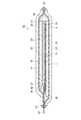
図1は、有機EL装置42の構成を模式的に示す断面図である。そして図2は、有機ELパネル41の構成を模式的に示す断面図である。図1に示すように、有機EL装置42は第1保護シート21と第3保護シート25とで有機ELパネル41(図2参照)をサンドイッチ状にはさんで保護している。 FIG. 1 is a cross-sectional view schematically showing the configuration of the
図2に示すように、有機ELパネル41は、第1基板としての素子基板1と第2基板としてのカラーフィルター基板16との一対の基板、及び該一対の基板と第1シール材31とで構成される領域内に形成された電気光学素子としての有機EL素子17等で構成されている。素子基板1とカラーフィルター基板16は、透明性を有する無機ガラス等からなり、第1シール材31により所定の間隔を持って対向配置されている。なお、本実施形態の有機ELパネル41はトップエミッション型であるため、素子基板1において透明性は必須ではない。 As shown in FIG. 2, the
素子基板1の上方には、各有機EL素子17をアクティブ駆動するための駆動用TFT3、及び図示しないスイッチング用TFTと保持容量等の素子を含む画素回路が形成されている。そして、該画素回路は、層間絶縁層2で覆われている。かかる駆動用TFT3等と層間絶縁層2を合わせて、以下、素子層13と称する。なお、「素子基板1の上方」とは、カラーフィルター基板16側の方向を意味している。また、有機EL素子17が規則的に配置された領域の周囲には、図示を省略しているが走査線駆動回路及びデータ線駆動回路等が形成されている。 Above the
画素回路の上方には、例えば、アクリル樹脂等の絶縁物からなる層である平坦化層4が形成されている。また、素子基板1の一辺がカラーフィルター基板16から張出した張出し部48には、外部接続端子46が形成されている。外部接続端子46は、平坦化層4に形成された図示しないコンタクトホールを介して、上述の走査線駆動回路等と導通しており、また、配線基板47を介して図示しない外部回路と導通している。 Above the pixel circuit, for example, a
平坦化層4の上層には、各駆動用TFT3毎に、反射層5と画素電極6とがこの順番で積層されている。反射層5は、例えばアルミニウム等からなり、発光機能層8から素子基板1側に向かう光をカラーフィルター基板16の方へ反射して、表示に寄与させる。画素電極6は、ITO(酸化インジウム・合金)や、ZnO等の透明導電材料で形成されており、各駆動用TFT3のドレイン端子と平坦化層4を貫通するコンタクトホールを介して電気的に接続されている。隔壁7は、光硬化性の黒色樹脂等から構成され、平面視で各画素電極6を囲むように形成されている。駆動用TFT3を含む画素回路は、光による誤動作を防止するために、平面視で隔壁7と重なるように配置されている。 On the
画素電極6の上方には、発光機能層8と共通電極9とが該画素電極及び隔壁7を覆うように形成されている。発光機能層8は、本図においては一層の構成として図示されているが、実際は、正孔注入層、正孔輸送層、有機EL層、電子注入層等から構成されており、画素電極6上にこの順番に積層されている。正孔輸送層は、芳香族ジアミン(TPAB2Me−TPD,α−NPD)等の昇華性を有する材料から構成されている。有機EL層は、通電により白色光を放射する有機材料薄膜から構成されている。電子注入層は、LiF(フッ化リチウム)等から構成されている。 A light emitting
共通電極9は、MgAg等の金属を、光が透過するようにごく薄く成膜した金属薄膜層である。有機EL素子17は、画素電極6と共通電極9との一対の電極と該一対の電極間に形成された発光機能層8とで構成されている。画素電極6と共通電極9との間に電圧が印加されると、正孔注入層から供給される正孔と電子注入層から供給される電子とが有機EL層内で結合して上述の白色光が生じ、後述するカラーフィルター層14により三原色光のいずれかの光となってカラーフィルター基板16越しに射出される。 The
カラーフィルター基板16の発光機能層8側には、赤色カラーフィルター14r、緑色カラーフィルター14g、及び青色カラーフィルター14bを有するカラーフィルター層14が形成されている。夫々のカラーフィルター14(r,g,b)、は、平面視で画素領域毎に、すなわち隔壁7で区画された領域毎に配置されている。各有機EL素子17において発光機能層8が通電されることにより生じる白色光は、カラーフィルター層14を透過することで所定の波長領域の光が取り出されて、赤色光、緑色光、青色光すなわち三原色光のいずれかの光となる。そして、かかる三原色光が画素領域29から射出されることにより、複数の画素領域29が規則的に配置された領域である表示領域にカラー画像が形成される。なお、画素領域29は平面的な概念であり、平面視において後述する遮光層(ブラックマトリクス)14bmに囲まれた領域である。遮光層14bmは平面視で隔壁7と重なるように格子状に形成されており、画素領域29間の混色を抑制している。 On the light emitting
有機EL素子17とカラーフィルター層14との間には、電極保護層10と緩衝層11とガスバリア層12と第1封止樹脂層35とが順に形成されている。電極保護層10と緩衝層11とガスバリア層12とを合わせて、以下、薄膜封止層15と称する。電極保護層10は、SiO2や、Si3N4等の透明で、かつ、水分を遮断する機能を有する材質から構成されている。緩衝層11は、熱硬化性のエポキシ樹脂等の透明な有機緩衝層である。ガスバリア層12は、SiO2や、Si3N4等の透明で、かつ、水分を遮断する機能を有する封止層であり、発光機能層8への水分の浸入を防止する機能を有している。第1封止樹脂層35は、例えば、熱硬化性のエポキシ樹脂等からなる透明な接着層であり、ガスバリア層12とカラーフィルター層14との間の凹凸面に充填されるとともに、両者を接着する。また、外部から、発光機能層8への水分の浸入を防ぐ機能も果たしている。Between the
なお、本図においては、各構成要素の積層関係を明確にするために、素子基板1とカラーフィルター基板16との間に挟持された各層の縮尺を上述の一対の基板(1,16)よりも拡大している。しかし、実際は、上述の一対の基板(1,16)の間隔は基板の板厚よりも薄く形成されている。具体的には上述の間隔は数μm〜10μm程度の厚さである。一方、素子基板1及びカラーフィルター基板16の厚さは、双方とも20μmないし50μmである。かかる厚さであれば、ガラスからなる基板であっても柔軟性を発揮できる。 In this figure, the scale of each layer sandwiched between the
図1に示すように、第1保護シート21は第1接着層22により素子基板1の裏面に貼付されており、第3保護シート25は第3接着層26によりカラーフィルター基板16の裏面に貼付されている。なお、裏面とは、第1封止樹脂層35に対向する面の反対側の面である。双方の保護シート(21,25)は双方の(上述の一対の)基板(1,16)よりも大面積であり、平面視で基板(上述の一対の基板)の外側においては、該双方の保護シートが基板を介さずに対向している。すなわち双方の接着層(22,26)が基板(上述の一対の基板)を介さずに対向している。そのうち外部接続端子46が形成されている側では、双方の接着層(22,26)は配線基板47を介して互いに接着されており、もう一方の側では直接接着されている。 As shown in FIG. 1, the first
そして、双方の基板(1,16)の端面あるいは第1シール材31と、双方の接着層(22,26)が接着されている部分との間の間隙には第2封止樹脂層36が充填されている。そして、双方の保護シート(21,25)の端面には第3封止樹脂層37が配置されている。すなわち、該端面は第3封止樹脂層37で封止されており、外部に対して遮断されている。 The second
此処で、上記の従来技術で述べたように、従来の有機EL装置は双方の保護シート(21,25)を有機ELパネル41が形成された後に貼付している。一方、後述するように、本実施形態の有機ELパネルの製造方法では、上述の(分割前の)パネル集合体に貼付された保護シートをそのまま第1保護シート21として利用している。以下、本実施形態の有機ELパネルの製造方法について述べる。 Here, as described in the above prior art, in the conventional organic EL device, both protective sheets (21, 25) are pasted after the
<有機ELパネルの製造方法>
次に、本実施形態に係る有機EL装置の製造方法について述べる。まず、パネル集合体43とシート積層体20について述べた後、工程断面図により上記製造方法について述べる。
なお、図1に示すように、第1保護シート21の形状(大きさ)は、第3保護シート25と併せて有機ELパネル41を封止できるように、十分な大きさを有している。しかし、以下に示す各図においては、便宜上、第1保護シート21を素子基板1よりも若干大きい程度に図示している。<Method for producing organic EL panel>
Next, a method for manufacturing the organic EL device according to this embodiment will be described. First, after describing the
As shown in FIG. 1, the shape (size) of the first
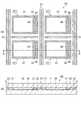
図3は、パネル集合体43の概略図である。図3(a)はパネル集合体43の素子基板1側を示す平面図であり、図3(b)は図3(a)のA−A’線に断面図である。なお、本図はパネル集合体43の全体の内の4つの有機ELパネル41が形成された領域を切り取って示すものであり、実際にはより多数の有機ELパネル41が形成されていてもよい。 FIG. 3 is a schematic view of the
図3(a)に示すように、パネル集合体43は、複数の有機ELパネル41が所定の間隔を空けて規則的に配置されてなる。なお、本図では有機ELパネル41がマトリクス状に配置されているが、配置の態様はそれに限定されるものではない。本図において、平面視で第1シール材31又は第2シール材32が形成された領域、及び該双方のシール材の内側の領域が、個々の有機ELパネル41が占める領域である。 As shown in FIG. 3A, the
そのうち、第1シール材31形成された領域と該第1シール材の内側の領域が、平面視でカラーフィルター基板16が占める領域である。平面視でカラーフィルター基板16が占める領域の外側の領域が張出し部48であり、外部接続端子46が形成されている。なお、第1シール材31の内側には有機EL素子17が規則的に形成され、さらには走査線駆動回路等も形成されているが、本図では図示を省略している。 Of these, the area where the
図1に示すように、配線基板47が配置されていない側では双方の基板(1,16)の端面は第1シール材31の外側に若干はみ出しているが、本図及び以下に示す各図においては、上記端面と第1シール材31の外周の線は、平面視で一致するように図示している。また、図3(b)においては、平坦化層4と薄膜封止層15とカラーフィルター層14の図示を省略している。 As shown in FIG. 1, on the side where the
隣り合う有機ELパネル41間には、第3シール材33が形成されている。該第3シール材は、図3(b)に示すように有機ELパネル41が配置されていない領域において素子基板1とカラーフィルター基板16と間隔を一定に保つ機能を果たしている。また、後述するパネル集合体43の分割時において、双方の基板(1,16)の不要な部分(後述する非パネル部)を除去し易くしている。パネル集合体43が形成された段階では、双方の基板(1,16)は薄板化されていない。したがって、該双方の基板は元々の厚さである0.3mm〜0.7mmの基板厚を有している。なお、かかるパネル集合体43を形成する工程が、第1工程である。 A
図4は、第1保護シート21と第2保護シート23とを積層されてなるシート積層体20の構成等を示す図である。図4(a)は、上記2層の保護シート(21,23)を積層した状態を示している。図4(b)は、上述の若干の加工を施した状態を示す平面図であり、図4(c)は、該平面図のB−B’線における断面図である。該若干の加工とは、第1接着層22のパターニングと環状溝部27の形成である。 FIG. 4 is a diagram illustrating a configuration and the like of the
双方の保護シート(21,23)は夫々接着層(22,24)と積層されているので、第1保護シート21は第2接着層24に面接着されている。かかる第1保護シート21の裏面を第2接着層24に面接着する工程が、第3工程である。保護シート(21,23)の接着層(22,24)が配置されている側の面が表面であり、その反対側の面が裏面である。なお、保護シート(21,23)は接着層(22,24)が配置された状態で流通しているため、保護シート(21,23)は「基材」もしくは「基材フィルム」と称することもできる。 Since both of the protective sheets (21, 23) are laminated with the adhesive layers (22, 24), the first
本実施形態では双方の保護シート(21,23)は異なる材料で構成されている。第2保護シート23と第2接着層24との積層体は、電気化学工業株式会社製のエレグリップUVテープである商品名「UDT−1025MC」が用いられている。該テープは、第2保護シート23である基材としては透明性を有するPET樹脂が用いられており、第2接着層24としては紫外線(UV)の照射により粘着力が大幅に低下するアクリル酸エステル系共重合体が用いられている。なお、第2保護シート23は上記の材料に限定されるわけではなく、例えば、ポリエチレン、ポリプロピレン等を用いることもできる。 In the present embodiment, both protective sheets (21, 23) are made of different materials. As the laminate of the second
一方、第1保護シート21と第1接着層22との積層体は、上述の積層体とは異なる性質の材料を組み合わせて形成されている。具体的には、不透明性材料からなる第1保護シート21か、紫外線が照射されても接着力が低下しない材料からなる第1接着層22のいずれかが組み合わされている。不透明性材料からなる第1保護シート21と紫外線が照射されても接着力が低下しない材料からなる第1接着層22とが組み合わされていてもよい。本実施形態においては、第1保護シート21は不透明性材料であるふっ素樹脂で形成されており、第1接着層22は紫外線が照射されても接着力が低下しない材料であるエポキシ樹脂等の熱硬化性樹脂で形成されている。 On the other hand, the laminated body of the
本実施形態の製造方法ではシート積層体20を形成した後、上述の若干の加工、すなわち第1接着層22のパターニングと環状溝部27の形成を行っている。第1接着層22のパターニングが第12工程であり、環状溝部27の形成が第4工程である。 In the manufacturing method of the present embodiment, after the
本実施形態の製造方法における第1接着層22のパターニングは、図3(a)に示す有機ELパネル41の形成領域と第3シール材33の形成領域、及び併進する該第3シール材に挟まれた帯状の領域の計3種類の領域に対応する領域に、第1接着層22を残し、それ以外の領域から該第1接着層を除去するように行われる。したがって、第1接着層22は、図4(b)に示すように、マトリクス状に配置された方形のパターンと該方形のパターン間に縦横に延在する帯状のパターンの2種類のパターンにパターニングされる。 The patterning of the first
環状溝部27は、図4(c)に示すように、第1保護シート21及び第2接着層24を貫通して第2保護シート23に達するまで掘られた溝である。そして該環状溝部は、有機ELパネル41の形成領域に対応する領域を若干の間隔を持って囲む、所定の幅を有する環状の領域に形成されている。したがって、本実施形態の製造方法では、図4(b)に示すように、第1接着層22が除去されて第1保護シート21が露出している領域に環状溝部27が形成される。 As shown in FIG. 4C, the
次に、シート積層体20を用いてパネル集合体43を個々の有機ELパネル41に分割する方法(工程)を、図5等の工程断面図を用いて述べる。
まず、図5(a)に示すように、素子基板1を、フッ酸(フッ化水素酸)等をエッチング液として用いるウェットエッチング、あるいは機械的研磨法、あるいは化学的研磨法等により裏面側から薄板化して、パネル集合体43全体を薄型化する。かかる薄型化の工程が第2工程である。素子基板1の薄板化は、元々の0.3mm〜0.7mmの基板厚が、20μm〜50μmの基板厚となるまで行う。Next, a method (process) for dividing the
First, as shown in FIG. 5A, the
次に、図5(b)に示すように、パネル集合体43の素子基板1側にシート積層体20を貼り合せる。かかる貼り合せ工程が、第5工程である。該貼り合せは、パターニングされた第1接着層22と有機ELパネル41等が、平面視で一致するように位置合せして行う。図4(c)等に示すように、第1接着層22は表面が露出した状態にあるので、シート積層体20の第1接着層22側にパネル集合体43を重ねて加圧すれば、該シート積層体が貼付される。 Next, as illustrated in FIG. 5B, the
次に、図5(c)に示すように、カラーフィルター基板16を裏面側から薄板化して、パネル集合体43全体をさらに薄型化する。薄板化の方法は、素子基板1の薄板化の方法と同様であり、カラーフィルター基板16は20μm〜50μmの厚さになるまで薄板化される。かかる工程が第6工程である。該第6工程により、パネル集合体43の厚さは50μm乃至110μmとなる。 Next, as shown in FIG. 5C, the
次に、図6(a)の矢印で示すように、パネル集合体43のカラーフィルター基板16側からレーザー照射して、カラーフィルター基板16及び素子基板1を分割する。かかる工程が第7工程である。該レーザー照射は、将来的に有機ELパネル41の素子基板1となる領域の外周線に沿って行われる。パネル集合体43におけるかかる「将来的に有機ELパネルの素子基板となる領域」に相当する部分がパネル部51であり、それ以外の部分が非パネル部52である。ここで、上記外周線に沿う領域における第1接着層22は、既にパターニング(除去)されている。したがって、上述のレーザー照射によって生じる溝は、第1保護シート21の表面まで達する。ここで、将来的に素子基板1となる領域以外の領域の一部には、図3(a)に示すように第3シール材33が形成されている。したがって、分割されたカラーフィルター基板16も、保持されている。 Next, as indicated by the arrows in FIG. 6A, the
次に、図6(b)に示すように、パネル集合体43から、上述の第7工程すなわちレーザー照射によって生じた非パネル部52を除去する。同時に、非パネル部52に付属するシート積層体の一部、すなわち環状溝部27で区画された網状(格子状)の領域における第1接着層22と第1保護シート21と第2接着層24の積層体を除去する。ここで、シート積層体20における上述の網状の領域は、平面視で非パネル部52に含まれている。そして、該網状の領域の第1保護シート21は、第1接着層22により、非パネル部52の素子基板1に接着されている。したがって、非パネル部52と上記網状の領域における第1保護シート21とは一括して除去できる。かかる工程が第8工程である。なお、第2接着層24については完全に除去しなくてもよい。 Next, as shown in FIG. 6B, the
かかる工程を経ることにより、第2保護シート23上に、張出し部48(図2参照)が第2シール材32とカラーフィルター基板16の一部とで密封された状態の有機ELパネル41と略方形の第1保護シート21との積層体が、マトリクス状に配置された状態となる。外部接続端子46は、この段階では露出していない。なお、以下の記載において、上述の「第2シール材32とカラーフィルター基板16の一部とで覆われた状態の有機ELパネル41」も、単に「有機ELパネル41」と表記する。 Through this process, the
次に、図6(b)に示す状態の有機ELパネル41と略方形の第1保護シート21との積層体を、第2保護シート23で保持したままで、ガラスをエッチング可能なエッチング液に浸漬する。そして、双方の基板(1,16)の端部に丸め処理を施す。かかる丸め処理工程が、第10工程である。 Next, while the laminated body of the
図7に、かかる丸め処理を施した結果を示す。図7(a)は丸め処理を施す前の状態を示す図であり、図7(b)は丸め処理を施した後の状態を示す図である。図示するように、処理前の段階ではレーザー照射で切断されたため、基板面に垂直な面で構成されていた上記端部に、図7(b)の矢印で示すような丸みが形成される。 FIG. 7 shows the result of such rounding processing. FIG. 7A is a diagram illustrating a state before the rounding process is performed, and FIG. 7B is a diagram illustrating a state after the rounding process is performed. As shown in the drawing, since it was cut by laser irradiation at the stage before processing, roundness as shown by an arrow in FIG. 7B was formed at the end portion constituted by a surface perpendicular to the substrate surface.
図7(a)に示すような、基板面と該基板面に垂直な面とで構成される端部は、衝撃等が加えられた場合にクラックが発生しやすい。そして、かかるクラックは、有機ELパネルの(衝撃等に対する)耐久性を劣化させる。本工程による丸め処理によれば上記の耐久性が増すため、かかる有機ELパネルあるいは該有機ELパネルを有する電子機器等の信頼性を向上させることができる。 As shown in FIG. 7A, an end portion constituted by a substrate surface and a surface perpendicular to the substrate surface is likely to crack when an impact or the like is applied. Such cracks degrade the durability of the organic EL panel (with respect to impact or the like). According to the rounding process in this step, the durability is increased, so that the reliability of the organic EL panel or an electronic device having the organic EL panel can be improved.
また、上述した従来の有機ELパネルの製造方法では、シート積層体20を用いていないため、パネル集合体を分割する際に保護シートも分割される。したがって、丸め処理は個々の有機ELパネル毎に行う必要がある。双方の基板(1,16)が薄板化された後の個々の有機ELパネル41に丸め処理を施すことは、破損等の原因となり得る。また、個々に処理することは、製造コストを上昇させる。本実施形態にかかる製造方法であれば、かかる丸め処理を、複数の有機ELパネル41を第2保護シート23で保持したままで一括して行うことができる。したがって、破損等が生じる可能性を低減でき、かつ製造コストも低減できる。 Further, in the above-described conventional method for manufacturing an organic EL panel, since the
以下、有機ELパネルの製造方法の説明を続ける。上述の丸め処理を施した後、図6(c)に示すように、平面視で張出し部48と第1シール材31との境界にカラーフィルター基板16側からレーザー照射を施して、該境界でカラーフィルター基板16を分割する。前回のレーザー照射と異なり、本工程ではレーザーが素子基板1には達しないように出力を調節して行う。すなわち、切断する基板はカラーフィルター基板16のみである。 Hereinafter, the description of the manufacturing method of the organic EL panel will be continued. After performing the above-described rounding process, as shown in FIG. 6C, laser irradiation is performed from the
次に、図8(a)に示すように、カラーフィルター基板16の張出し部48と重なる部分、すなわち前工程のレーザー照射で分割された部分を、第2シール材32ごと除去する。そして、外部接続端子46を露出させる。かかる工程が第11工程である。 Next, as shown in FIG. 8A, the portion overlapping the overhanging
次に、図8(b)に示すように、第2保護シート23側から紫外線を全面的に照射する。上述したように、第2接着層24は紫外線の照射により接着力が低下する材料で形成されている。したがって、本工程により、第2接着層24と第1保護シート21との界面の接着力が低下する。一方で、上述したように第1保護シート21は紫外線を透過しない不透明性材料で形成されており、第1接着層22は紫外線が照射されても接着力が低下しない材料で形成されている。したがって、上述の紫外線照射によっても第1接着層22の接着力は維持される。 Next, as shown in FIG. 8B, the whole surface is irradiated with ultraviolet rays from the second
次に、図8(c)及び図8(d)に示すように、有機ELパネル41と略方形に区画された第1保護シート21との積層体を、第2保護シート23から取り外す。かかる工程が第9工程である。上記したように第2接着層24の接着力は低下しており、第1接着層22の接着力は維持されているので、上述の積層体は容易に取り外すことができる。図8(c)は取り外された該積層体の断面図であり、図8(d)は該積層体の平面図である。ここで、上述の丸め処理工程を実施している間、第1保護シート21は第2保護シート23で被われている。したがってエッチング液にエッチング滓が混在していても、第1保護シート21に該エッチング滓が付着することを回避できる。そのため、図8(c)に示す第1保護シート21は除去(剥離)する必要がなく、有機EL装置42の構成要素としてそのまま用いることができる。したがって、以下、配線基板47(図1参照)を外部接続端子46と導通が得られるように接着して、第3保護シート25を貼付し、第2封止樹脂層36及び第3封止樹脂層37等の構成要素を加えることで、有機EL装置42を形成することができる。 Next, as shown in FIG. 8C and FIG. 8D, the laminate of the
<本実施形態の効果>
上述したように、本実施形態の有機ELパネルの製造方法によれば、パネル集合体43を構成する一対の基板(1,16)を薄板化した後、該パネル集合体を分割して個々の有機ELパネル41とした後でも、第2保護シートにより複数の有機ELパネル41をまとめて保持できる。したがって、個々の有機ELパネル41をハンドリングすることなく、丸め処理等の工程を一括して実施できる。したがって、作業効率が向上すると共に、有機ELパネル41が破損する可能性も低減できる。<Effect of this embodiment>
As described above, according to the method for manufacturing the organic EL panel of the present embodiment, after the pair of substrates (1, 16) constituting the
また、従来の製造方法においても基板(1,16)を薄板化する際に用いていた保護シート(第1保護シート21)をそのまま有機EL装置42の構成要素として用いることができるため。したがって、保護シートの除去(剥離)と再貼付に要する工程を省くことができ、製造コストと材料コストを低減できる。 Further, since the protective sheet (first protective sheet 21) used in the conventional manufacturing method when the substrate (1, 16) is thinned can be used as it is as a component of the organic EL device. Therefore, the steps required for removing (peeling) and reattaching the protective sheet can be omitted, and the manufacturing cost and material cost can be reduced.
(変形例)
上記の実施形態においては、シート積層体20とパネル集合体43とを貼り合せる前に、該シート積層体に環状溝部27を形成する第4工程と共に、平面視で有機ELパネル41に対応する領域の周囲を囲む環状の領域から第1接着層22を除去して第1保護シート21を露出させる第12工程をさらに実施している。しかし本発明の具体化においてはかかる工程は必須ではなく、環状溝部27の形成のみ実施する形態も可能である。環状溝部27さえ形成すれば、第2保護シート23から第1保護シート21と有機ELパネル41との積層物を取り外すことは可能であり、工程数も削減できる。(Modification)
In the above embodiment, before bonding the
1…第1基板としての素子基板、2…層間絶縁層、3…駆動用TFT(薄膜トランジスター)、4…平坦化層、5…反射層、6…画素電極、7…隔壁、8…発光機能層、9…共通電極、10…電極保護層、11…緩衝層、12…ガスバリア層、13…素子層、14…カラーフィルター層、14b…青色カラーフィルター、14bm…遮光層、14g…緑色カラーフィルター、14r…赤色カラーフィルター、15…薄膜封止層、16…第2基板としてのカラーフィルター基板、17…電気光学素子としての有機EL素子、20…シート積層体、21…第1保護シート、22…第1接着層、23…第2保護シート、24…第2接着層、25…第3保護シート、26…第3接着層、27…環状溝部、29…画素領域、31…第1シール材、32…第2シール材、33…第3シール材、35…第1封止樹脂層、36…第2封止樹脂層、37…第3封止樹脂層、41…表示パネルとしての有機ELパネル、42…有機EL装置、43…パネル集合体、46…外部接続端子、47…配線基板、48…張出し部、51…パネル部、52…非パネル部。 DESCRIPTION OF
Claims (8)
Translated fromJapanese前記パネル集合体を前記第1基板側から薄型化する第2工程と、
表面に第1接着層を有する第1保護シートの裏面に、表面に第2接着層を有する第2保護シートを前記第2接着層を介して貼り合せてシート積層体を形成する第3工程と、
前記シート積層体に、平面視で前記表示パネルに対応する領域の周囲を所定の間隔を空けて囲む、前記第2保護シートに達する環状溝部を形成する第4工程と、
前記第1基板側から薄型化された前記パネル集合体の前記第1基板側に、前記環状溝部が形成された前記シート積層体を、平面視で前記表示パネルが前記環状溝部内に収まるように前記第1接着層を介して貼り合せる第5工程と、
前記シート積層体が貼り合された前記パネル集合体を前記第2基板側から薄型化する第6工程と、
双方の側から薄型化された前記パネル集合体を、平面視で前記表示パネルを含むパネル部と該パネル部以外の部分である非パネル部とに分割する第7工程と、
分割された前記非パネル部を、前記第1保護シートの前記環状溝部で囲まれた領域の外側の部分と共に前記パネル集合体から取り除く第8工程と、
前記第2接着層の接着力を低下させて、前記第2保護シートから、前記環状溝部で囲まれた前記第1保護シートと前記表示パネルとの積層物を取り外す第9工程と、
を有することを特徴とする表示パネルの製造方法。A plurality of electrical element groups each including a plurality of electrical elements are formed on one surface of the first substrate so as to be spaced apart from each other, and then the second substrate and the first substrate are viewed in plan view. A first step of forming a panel aggregate including a plurality of display panels by bonding via a sealing material surrounding a formation region of the element group;
A second step of thinning the panel assembly from the first substrate side;
A third step of forming a sheet laminate by bonding a second protective sheet having a second adhesive layer on the surface to the back surface of the first protective sheet having the first adhesive layer on the surface via the second adhesive layer; ,
A fourth step of forming, in the sheet laminate, an annular groove that reaches the second protective sheet, surrounding the area corresponding to the display panel in a plan view with a predetermined interval;
The sheet laminated body in which the annular groove is formed on the first substrate side of the panel assembly thinned from the first substrate side so that the display panel fits in the annular groove in a plan view. A fifth step of bonding through the first adhesive layer;
A sixth step of thinning the panel assembly to which the sheet laminate is bonded from the second substrate side;
A seventh step of dividing the panel aggregate thinned from both sides into a panel portion including the display panel and a non-panel portion other than the panel portion in plan view;
Removing the divided non-panel portion from the panel assembly together with the outer portion of the region surrounded by the annular groove portion of the first protective sheet;
A ninth step of reducing the adhesive force of the second adhesive layer and removing the laminate of the first protective sheet and the display panel surrounded by the annular groove from the second protective sheet;
A method for producing a display panel, comprising:
前記第1工程は、同一のエッチング液でエッチング可能な材料からなる前記第1基板と前記第2基板とを用いて前記パネル集合体を形成する工程であり、
前記第8工程と前記第9工程との間に、前記シート積層体が貼り合された前記パネル集合体を前記エッチング液に浸す第10工程をさらに実施することを特徴とする表示パネルの製造方法。A manufacturing method of a display panel according to claim 1,
The first step is a step of forming the panel aggregate using the first substrate and the second substrate made of a material that can be etched with the same etchant.
A method for manufacturing a display panel, further comprising a tenth step of immersing the panel assembly in which the sheet laminate is bonded between the eighth step and the ninth step in the etching solution. .
前記電気素子は電気光学素子と外部接続端子とを含み、
前記シール材は第1シール材と第2シール材とからなり、
前記第1工程は前記電気光学素子の形成領域を囲むように前記第1シール材を形成し、かつ、前記外部接続端子の形成領域を前記第1シール材の一部と共に囲むように前記第2シール材を形成する工程であり、
前記第10工程を実施後、前記第9工程を実施する前に、
前記第2基板の一部を分割除去して、前記外部接続端子の形成領域を平面視で露出させる第11工程をさらに実施することを特徴とする表示パネルの製造方法。It is a manufacturing method of the display panel according to claim 1 or 2,
The electric element includes an electro-optical element and an external connection terminal,
The sealing material comprises a first sealing material and a second sealing material,
In the first step, the first sealing material is formed so as to surround the formation region of the electro-optical element, and the second connection is provided so as to surround the formation region of the external connection terminal together with a part of the first sealing material. A step of forming a sealing material,
After carrying out the tenth step and before carrying out the ninth step,
A method of manufacturing a display panel, further comprising performing an eleventh step of partially removing the second substrate to expose a region where the external connection terminal is formed in plan view.
前記第2接着層は紫外線の照射により接着力が低下する性質を有しており、
前記第9工程は、前記シート積層体の前記第2保護シート側から紫外線を照射することで前記第2接着層の接着力を低下させた後に前記積層物を前記第2保護シートから取り外す工程であることを特徴とする表示パネルの製造方法。It is a manufacturing method of the display panel as described in any one of Claims 1-3, Comprising:
The second adhesive layer has a property that the adhesive strength is reduced by irradiation with ultraviolet rays,
The ninth step is a step of removing the laminate from the second protective sheet after reducing the adhesive force of the second adhesive layer by irradiating ultraviolet rays from the second protective sheet side of the sheet laminate. A method for manufacturing a display panel, comprising:
前記第7工程は、平面視で前記表示パネルを含む領域の外周線に沿ってレーザーを照射することにより前記パネル集合体を分割する工程であることを特徴とする表示パネルの製造方法。It is a manufacturing method of the display panel as described in any one of Claims 1-4,
The method of manufacturing a display panel, wherein the seventh step is a step of dividing the panel aggregate by irradiating a laser along an outer peripheral line of a region including the display panel in a plan view.
前記第11工程は、レーザーを照射することにより前記第2基板を切断して該切断部を除去する工程であることを特徴とする表示パネルの製造方法。It is a manufacturing method of the display panel as described in any one of Claims 1-4,
The eleventh step is a method of manufacturing a display panel, wherein the second substrate is cut by irradiating a laser to remove the cut portion.
前記第3工程と前記第5工程との間に、
前記シート積層体の、平面視で前記表示パネルに対応する領域の周囲を囲む環状の領域から、前記第1接着層を除去して前記第1保護シートを露出させる第12工程をさらに実施することを特徴とする表示パネルの製造方法。A manufacturing method of a display panel according to any one of claims 1 to 6,
Between the third step and the fifth step,
Further performing a twelfth step of removing the first adhesive layer and exposing the first protective sheet from an annular region surrounding the periphery of the region corresponding to the display panel in plan view of the sheet laminate. A display panel manufacturing method characterized by the above.
前記第12工程は、前記環状の領域が平面視で前記環状溝部を含むように前記第1接着層を除去する工程であることを特徴とする表示パネルの製造方法。It is a manufacturing method of the display panel according to claim 7,
The method according to claim 12, wherein the twelfth step is a step of removing the first adhesive layer so that the annular region includes the annular groove portion in a plan view.
Priority Applications (1)
| Application Number | Priority Date | Filing Date | Title |
|---|---|---|---|
| JP2009204435AJP2011053582A (en) | 2009-09-04 | 2009-09-04 | Method for manufacturing display panel |
Applications Claiming Priority (1)
| Application Number | Priority Date | Filing Date | Title |
|---|---|---|---|
| JP2009204435AJP2011053582A (en) | 2009-09-04 | 2009-09-04 | Method for manufacturing display panel |
Publications (1)
| Publication Number | Publication Date |
|---|---|
| JP2011053582Atrue JP2011053582A (en) | 2011-03-17 |
Family
ID=43942617
Family Applications (1)
| Application Number | Title | Priority Date | Filing Date |
|---|---|---|---|
| JP2009204435AWithdrawnJP2011053582A (en) | 2009-09-04 | 2009-09-04 | Method for manufacturing display panel |
Country Status (1)
| Country | Link |
|---|---|
| JP (1) | JP2011053582A (en) |
Cited By (13)
| Publication number | Priority date | Publication date | Assignee | Title |
|---|---|---|---|---|
| JP2013242567A (en)* | 2012-05-22 | 2013-12-05 | Spigen Sgp Korea | Toughened glass protective film for portable electronic device |
| JP2014021498A (en)* | 2012-07-13 | 2014-02-03 | Samsung Display Co Ltd | Display panel manufacturing method |
| JP2015170502A (en)* | 2014-03-07 | 2015-09-28 | 新日鉄住金化学株式会社 | Manufacturing method for display device |
| WO2017002372A1 (en)* | 2015-07-01 | 2017-01-05 | シャープ株式会社 | Method for manufacturing display device |
| JP2017117688A (en)* | 2015-12-25 | 2017-06-29 | 株式会社ジャパンディスプレイ | Display device |
| JP2017123216A (en)* | 2016-01-04 | 2017-07-13 | 株式会社ジャパンディスプレイ | Display device and manufacturing method thereof |
| WO2017199928A1 (en)* | 2016-05-16 | 2017-11-23 | 株式会社Nsc | Method for manufacturing display device |
| US10164215B2 (en) | 2013-06-12 | 2018-12-25 | Seiko Epson Corporation | Electro-optic device that prevents deterioration of a light emitting element |
| JP2019080099A (en)* | 2017-10-20 | 2019-05-23 | 株式会社トーキン | Piezoelectric acoustic module and OLED display device |
| TWI683169B (en)* | 2014-07-25 | 2020-01-21 | 日商半導體能源研究所股份有限公司 | Stacked structure, input/output device, information processing device, and manufacturing method of stacked structure |
| JP2020140968A (en)* | 2013-09-06 | 2020-09-03 | 株式会社半導体エネルギー研究所 | Light emitting device |
| WO2021045089A1 (en)* | 2019-09-04 | 2021-03-11 | 株式会社Nsc | Organic el panel |
| CN113097279A (en)* | 2021-03-31 | 2021-07-09 | 京东方科技集团股份有限公司 | Display panel and preparation method thereof |
- 2009
- 2009-09-04JPJP2009204435Apatent/JP2011053582A/ennot_activeWithdrawn
Cited By (20)
| Publication number | Priority date | Publication date | Assignee | Title |
|---|---|---|---|---|
| JP2013242567A (en)* | 2012-05-22 | 2013-12-05 | Spigen Sgp Korea | Toughened glass protective film for portable electronic device |
| JP2014021498A (en)* | 2012-07-13 | 2014-02-03 | Samsung Display Co Ltd | Display panel manufacturing method |
| US10164215B2 (en) | 2013-06-12 | 2018-12-25 | Seiko Epson Corporation | Electro-optic device that prevents deterioration of a light emitting element |
| US11355729B2 (en) | 2013-09-06 | 2022-06-07 | Semiconductor Energy Laboratory Co., Ltd. | Light-emitting device and method for manufacturing light-emitting device |
| JP6995930B2 (en) | 2013-09-06 | 2022-01-17 | 株式会社半導体エネルギー研究所 | Light emitting device |
| JP2020140968A (en)* | 2013-09-06 | 2020-09-03 | 株式会社半導体エネルギー研究所 | Light emitting device |
| JP2015170502A (en)* | 2014-03-07 | 2015-09-28 | 新日鉄住金化学株式会社 | Manufacturing method for display device |
| TWI683169B (en)* | 2014-07-25 | 2020-01-21 | 日商半導體能源研究所股份有限公司 | Stacked structure, input/output device, information processing device, and manufacturing method of stacked structure |
| US11437601B2 (en) | 2014-07-25 | 2022-09-06 | Semiconductor Energy Laboratory Co., Ltd. | Manufacturing method of light-emitting semiconductor device with a plurality of spacers between two substrates |
| WO2017002372A1 (en)* | 2015-07-01 | 2017-01-05 | シャープ株式会社 | Method for manufacturing display device |
| JP2017117688A (en)* | 2015-12-25 | 2017-06-29 | 株式会社ジャパンディスプレイ | Display device |
| JP2017123216A (en)* | 2016-01-04 | 2017-07-13 | 株式会社ジャパンディスプレイ | Display device and manufacturing method thereof |
| JP2017207528A (en)* | 2016-05-16 | 2017-11-24 | 株式会社Nsc | Display device manufacturing method |
| WO2017199928A1 (en)* | 2016-05-16 | 2017-11-23 | 株式会社Nsc | Method for manufacturing display device |
| JP2019080099A (en)* | 2017-10-20 | 2019-05-23 | 株式会社トーキン | Piezoelectric acoustic module and OLED display device |
| WO2021045089A1 (en)* | 2019-09-04 | 2021-03-11 | 株式会社Nsc | Organic el panel |
| JP2021039904A (en)* | 2019-09-04 | 2021-03-11 | 株式会社Nsc | Organic EL panel |
| CN113097279A (en)* | 2021-03-31 | 2021-07-09 | 京东方科技集团股份有限公司 | Display panel and preparation method thereof |
| CN113097279B (en)* | 2021-03-31 | 2024-05-24 | 京东方科技集团股份有限公司 | Display panel and method for manufacturing the same |
| US12207490B2 (en) | 2021-03-31 | 2025-01-21 | Chengdu Boe Optoelectronics Technology Co., Ltd. | Method for treating transparent adhesive layer of protective film on display back plate of display panel |
Similar Documents
| Publication | Publication Date | Title |
|---|---|---|
| JP2011053582A (en) | Method for manufacturing display panel | |
| US9666832B2 (en) | Display device and method of manufacturing the same | |
| CN108417602B (en) | Method for manufacturing organic EL device, and electronic apparatus | |
| EP2838132B1 (en) | Flexible display and method of manufacturing a flexible display | |
| CN104218188B (en) | Display device and manufacture method thereof | |
| JP6191260B2 (en) | Electro-optical device and electronic apparatus | |
| CN104953039B (en) | EL display device and method for manufacturing EL display device | |
| KR101865469B1 (en) | Display device and manufacturing the same | |
| US9954199B2 (en) | Display device | |
| JP5407649B2 (en) | ELECTRO-OPTICAL DEVICE, ITS MANUFACTURING METHOD, AND ELECTRONIC DEVICE | |
| KR20150015257A (en) | Flexible display device | |
| CN104425550A (en) | Flexible organic electroluminescent device and method for fabricating the same | |
| KR20120022609A (en) | Organic el device, method of producing organic el device, and electronic apparatus | |
| KR20170061773A (en) | Display apparatus | |
| JP4512436B2 (en) | Display device and manufacturing method thereof | |
| WO2010079640A1 (en) | Organic electroluminescence display device and method for producing the same | |
| JP5493791B2 (en) | Manufacturing method of electro-optical device | |
| JP2011023265A (en) | Electro-optical device and manufacturing method therefor | |
| JP2015005386A (en) | Electro-optical device and electronic apparatus | |
| JP2011107432A (en) | Method of manufacturing electrooptical device | |
| JP5407648B2 (en) | Electro-optical device manufacturing method, electro-optical device, and electronic apparatus | |
| CN103123956B (en) | Organic light emitting display panel and manufacturing method thereof | |
| JP2011043724A (en) | Electrooptical device, method of manufacturing the same, and electric apparatus | |
| KR101986650B1 (en) | Organic Light Emitting Diode Display Device and Method for Manufacturing The Same | |
| JP2007087807A (en) | Manufacturing method of organic EL display device |
Legal Events
| Date | Code | Title | Description |
|---|---|---|---|
| A300 | Application deemed to be withdrawn because no request for examination was validly filed | Free format text:JAPANESE INTERMEDIATE CODE: A300 Effective date:20121106 |