JP2011049630A - 3d image processing apparatus and control method thereof - Google Patents
3d image processing apparatus and control method thereofDownload PDFInfo
- Publication number
- JP2011049630A JP2011049630AJP2009194029AJP2009194029AJP2011049630AJP 2011049630 AJP2011049630 AJP 2011049630AJP 2009194029 AJP2009194029 AJP 2009194029AJP 2009194029 AJP2009194029 AJP 2009194029AJP 2011049630 AJP2011049630 AJP 2011049630A
- Authority
- JP
- Japan
- Prior art keywords
- viewing
- video
- unit
- glasses
- viewing range
- Prior art date
- Legal status (The legal status is an assumption and is not a legal conclusion. Google has not performed a legal analysis and makes no representation as to the accuracy of the status listed.)
- Granted
Links
Images


Landscapes
- Testing, Inspecting, Measuring Of Stereoscopic Televisions And Televisions (AREA)
- Controls And Circuits For Display Device (AREA)
Abstract
Translated fromJapaneseDescription
Translated fromJapanese本発明は、3次元(3D)映像視聴において3D視聴効果を享受可能な視聴範囲を視聴者に提示する、3D映像処理装置とその制御方法に関するものである。 The present invention relates to a 3D video processing apparatus and a control method thereof that present a viewer with a viewing range in which a 3D viewing effect can be enjoyed in 3D (3D) video viewing.
視差を利用して視聴者の左右の眼に異なる映像を見せることで、擬似的に3D映像視聴を可能にする技術がある。眼鏡無しで視聴する裸眼方式には、例えば、シリンドリカルレンズを多数並列に配置して見え方を制限するレンチキュラスクリーン方式や、1枚の板に多数のスリットを形成して映像の見え方を制限するパララックスバリア方式が知られている。
特殊な眼鏡を用いた方式ではアナグリフ方式が知られている。赤及び青の補色関係にある2色で描かれたステレオペア画像を、共通の透過波長域をもたない2色の有色フィルタで見ることによって、この2色の画像が選択・分離されて立体視が可能となる。また、偏光を利用した偏光方式や、左右の映像を時分割表示してシャッタ式眼鏡を用いて左右の眼に異なる映像を見せる時分割方式が実用化されている。なお、時分割方式と偏光方式を組み合わせた時分割・偏光方式や、時分割方式と分光方式を組み合わせた時分割・分光方式も実用化されている。There is a technology that enables 3D video viewing in a pseudo manner by using disparity to show different videos to the left and right eyes of the viewer. For the naked-eye method for viewing without glasses, for example, a lenticular screen method in which a large number of cylindrical lenses are arranged in parallel to limit the appearance, or a large number of slits are formed on a single plate to limit the appearance of the image. A parallax barrier method is known.
Anaglyph method is known as a method using special glasses. By viewing a stereo pair image drawn with two colors that are complementary to each other in red and blue with a two-color filter that does not have a common transmission wavelength range, the two color images are selected and separated into a three-dimensional image. Visualization is possible. In addition, a polarization method using polarized light and a time division method in which left and right images are displayed in a time-division manner and different images are displayed on the left and right eyes by using shutter glasses are put into practical use. Note that a time division / polarization method combining a time division method and a polarization method, and a time division / spectral method combining a time division method and a spectroscopy method have been put into practical use.
これらの3D映像視聴方式には、3D視聴効果を奏する視聴範囲があり、視聴者はこの視聴範囲内で立体視像を視聴することが望ましい。そのため、視聴者が適切な視聴範囲内で画面を見るように案内表示を行う技術が、例えば特許文献1に開示されている。また、適正な視聴範囲を画面に表示せずに視聴者に適正な視聴位置を知らせる技術が、特許文献2に開示されている。 These 3D video viewing methods have a viewing range that provides a 3D viewing effect, and it is desirable for the viewer to view a stereoscopic image within this viewing range. Therefore, for example,
しかしながら、従来の技術では視聴位置と適正な視聴範囲との関係を視聴者が認知することが難しいという課題がある。例えば、特許文献1の技術では、リモートコントローラ(以下、リモコンと略称する)と表示装置との間の視聴距離を計算し、この距離が適切か否かを示す案内を表示部に表示する。しかし視聴距離だけでは、適正な視聴範囲を視聴者に示すことができないという問題があった。また特許文献2では、例えば適正な視聴範囲内に視聴者が位置する場合にのみ、点灯しているLEDが確認可能である。しかし適正な視聴範囲外では、LEDが見えないので、視聴位置が適正な視聴範囲から外れてしまった事に視聴者が気付かず、その位置のままで映像を見続けてしまう可能性がある。
そこで本発明は、視聴者がその視聴位置と3D映像の視聴可能な視聴範囲との関係を確実に認識できる3D映像処理装置及びその制御方法の提供を目的とする。However, the conventional technology has a problem that it is difficult for the viewer to recognize the relationship between the viewing position and the appropriate viewing range. For example, in the technique of
Accordingly, an object of the present invention is to provide a 3D video processing apparatus and a control method therefor, in which the viewer can reliably recognize the relationship between the viewing position and the viewing range in which 3D video can be viewed.
上記課題を解決するために、本発明に係る装置は、視聴位置と3D映像の視聴が可能な視聴範囲との位置関係を提示する機能を有する3D映像処理装置であって、前記視聴位置を検出する位置検出手段と、前記視聴範囲を示す情報を記憶している範囲情報記憶手段と、前記位置検出手段が検出した視聴位置を表す画像情報、及び前記視聴範囲を表す画像情報を含む位置表示画像を生成して表示手段に表示させるように制御する制御手段と、を備える。 In order to solve the above-described problem, an apparatus according to the present invention is a 3D video processing apparatus having a function of presenting a positional relationship between a viewing position and a viewing range in which 3D video can be viewed, and detects the viewing position. A position display image including position detection means, range information storage means for storing information indicating the viewing range, image information representing the viewing position detected by the position detection means, and image information representing the viewing range And control means for controlling to generate and display on the display means.
本発明によれば、現在の視聴位置と前記視聴範囲との関係を視聴者に提示できるので、前記視聴範囲の外にいる視聴者は前記視聴範囲を認識して視聴位置を変更することで3D映像効果を享受できる。 According to the present invention, since the relationship between the current viewing position and the viewing range can be presented to the viewer, the viewer outside the viewing range can recognize the viewing range and change the viewing position to change the viewing position. You can enjoy the video effect.
以下、本発明の各実施形態について説明する。 Hereinafter, each embodiment of the present invention will be described.
[第1実施形態]
図1は、一実施形態に係る3D映像処理装置100の構成例を示すブロック図である。3D映像処理装置100は、視聴者の視聴位置と3D映像の視聴が可能な視聴範囲との間の位置関係について提示機能を有する。システム全般の制御手段を構成する制御部(以下、制御部Aという)110は、図示しない操作ボタンやリモコンからのユーザ操作による要求に応じて、所望の映像表示を実現する。チューナ部103は、アンテナ部102からデジタル放送波の受信信号を受け取り、所望のチャンネルの映像及び音声情報を含む時分割多重化されたTS(トランスポートストリーム)データに復調し、これをデコード部105に出力する。[First embodiment]
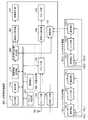
FIG. 1 is a block diagram illustrating a configuration example of a 3D video processing apparatus 100 according to an embodiment. The 3D video processing apparatus 100 has a presentation function regarding the positional relationship between the viewing position of the viewer and the viewing range in which 3D video can be viewed. A control unit (hereinafter referred to as control unit A) 110 that constitutes control means for the entire system realizes a desired video display in response to a request by a user operation from an operation button or a remote controller (not shown). The
デコード部105は前記TSデータを、映像及び音声の各データに分離し、デコード処理後の映像データを後段の映像出力制御部106に送出し、音声データを音声出力制御部108に送出する。またデコード部105は、外部入力部104から入力される情報やチューナ部103から入力されるTSデータに含まれる番組表の情報を処理する。外部入力部104からの入力信号に対してもデコード部105によるデコード処理が行われ、映像出力制御部106及び音声出力制御部108への伝送に適した信号が得られる。外部入力部104は、図示しない情報記録装置(DVDプレイヤー等)からの映像及び音声出力信号を受け、デコード部105は処理した映像信号を映像出力制御部106へ出力し、音声信号を音声出力制御部108へ出力する。なお、3D映像処理装置100は、ユーザ操作に従って2D(2次元)映像の視聴モードと3D映像の視聴モードの切替が可能である。3D映像処理装置100に入力された2D映像ソースの情報に基づいてユーザが3D映像を視聴する場合、所定のフォーマット変換が必要であり、デコード部105がその処理を担当する。ここで、3D映像視聴の方式について説明すると、特殊な眼鏡を使用して視聴者が立体映像を視聴する方式と、眼鏡無しで視聴者が立体映像を視聴する裸眼方式(直視型立体映像表示)がある。例えば、代表的な裸眼方式であるパララックスバリア方式では、表示素子にて右眼用の画素Rと左眼用の画素Lが縦列に交互に配置されている。表示素子の前方には、1枚の板にスリットを多数形成したバリアが配置されている。視聴者がこのバリアを通して表示素子を見た場合、右眼で表示素子の画素Rを見ることができ、左眼で表示素子の画素Lを見ることができる。視聴者は表示素子の画像を、両眼視差作用により立体映像として視聴できる。このような視聴方式に応じたフォーマット変換をデコード部105が行い、処理された3D映像信号が映像出力制御部106に出力され、音声信号が音声出力制御部108に出力される。 The
映像出力制御部106は、デコード部105が出力した映像信号を、映像表示部107の駆動信号に変換し、映像表示部107を制御する。これにより、映像表示部107は3D映像の視聴が可能な映像を表示する。但し3D映像の視聴時には、例えば、パララックスバリア方式の場合、映像表示部107の前面にスリットを多数形成したバリアが必要であるため、表示画面にフィルタが設けられている。音声出力制御部108は、デコード部105が出力した音声信号を、スピーカ部109の駆動信号に変換し、スピーカ部109から音声を出力させるように制御する。 The video
次に本発明の特徴である視聴者の視聴位置表示について説明する。視聴者の位置検出は位置判定部300で行う。カメラ部114は視聴者を撮像し、撮像データを検出部115に送出する。検出部115は、視聴者の顔の輪郭を形状認識し、左右対称な点、例えば視聴者の目や、眼鏡を着用した視聴者の場合において眼鏡フレームからレンズ部の位置を認識してそれらの位置を特定し、その左右対象物の中点を原点とし座標を取り込む。これにより、検出部115は視聴者の上下及び左右方向における位置を検出する。視聴者の前後方向における位置検出については、目又は眼鏡のレンズの間隔を検出部115にて予め設定しておく。例えば、設定値を6.5cmとした後、カメラ部114で視聴者を撮影し、設定値及び撮影した目や眼鏡レンズの間隔に基づいて、視聴者の前後方向の位置を計算することで、検出部115は該位置を検出できる。 Next, viewing position display of the viewer, which is a feature of the present invention, will be described. The position determination unit 300 detects the position of the viewer. The
範囲情報記憶部116には、3D映像を支障なく視聴可能な視聴範囲(以下、適正視聴範囲という)の情報が記憶されている。制御部A110は検出部115が検出した視聴者の位置情報と、範囲情報記憶部116に記憶された適正視聴範囲の情報との間で比較演算を行う。つまり、視聴者の検出位置(上下左右及び前後の位置)が、適正視聴範囲内に収まっているか又は当該範囲を逸脱しているかが判定される。この適正視聴範囲は、例えば左右方向の範囲が装置から30度以内であって、前後方向の範囲が装置から5メートル以内とされ、表示画面のインチサイズに比例する。 The range
位置表示画像作成部117は、前記比較演算による判定結果に基づいて視聴者の検出位置が適正視聴範囲内でない場合、記憶されている適正視聴範囲を表す画像情報に対し、視聴者の検出位置を表す画像情報を合成した画像データを生成する。この画像データは映像出力制御部106に伝送され、映像表示部107が位置表示画像を表示する。つまり位置表示画像は、視聴位置が適正視聴範囲に対して如何なる位置関係を有するかを視覚的に視聴者に提示するための画像である。なお、図中のジャンル判別部801については第3実施形態にて説明する。 If the detected position of the viewer is not within the proper viewing range based on the determination result by the comparison calculation, the position display
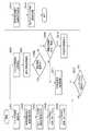
図2のフローチャートを用いて、位置判定部300にて視聴位置を検出し、制御部A110が比較演算を行った結果である位置表示画像の表示制御例について処理の流れを説明する。
S200にて制御部A110は、装置が3D映像視聴に係る3Dモードに入っているか否かを判定する。その結果、3Dモードの場合、S201へ進み、3Dモード以外の場合はそのまま処理を終了する。With reference to the flowchart of FIG. 2, a processing flow will be described for a display control example of a position display image, which is a result of detection of a viewing position by the position determination unit 300 and comparison control performed by the control unit A110.
In S200, control unit A110 determines whether or not the apparatus is in a 3D mode related to 3D video viewing. As a result, in the case of the 3D mode, the process proceeds to S201, and in the case other than the 3D mode, the process is ended as it is.
S201では、カメラ部114を用いて視聴者の撮像が行われ、撮像データが検出部115へ伝送される。次のS202にて検出部115は、視聴者の顔の輪郭情報に基づいて、視聴位置の座標情報を取得する。そしてS203では、範囲情報記憶部116に記憶されている適正視聴範囲を示すデータの読み出し処理が行われ、S204では、視聴者の検出位置が適正視聴範囲内であるか否かが判定される。つまりS202で検出した視聴者の位置情報と、S203で読み出した適正視聴範囲の情報との間の比較演算を制御部A110が行う。その結果に基づいて、視聴者の検出位置と適正視聴範囲との位置関係を制御部A110が識別する。視聴者の検出位置が適正視聴範囲から外れている場合、S205に進み、また該検出位置が適正視聴範囲内である場合には、S208へ進む。 In S <b> 201, a viewer is imaged using the
S205にて制御部A110は、S204で適正視聴範囲外と判定した視聴者の検出位置が、適正視聴範囲外にある時間を計測する。そして制御部A110はその計測時間が基準時間(例えば、3秒)以上であるか否かを判定する。その結果、視聴者の検出位置が基準時間以上に亘って適正視聴範囲外であった場合、S206に進むが、そうでない場合にはS208に進む。なお、基準時間の設定については固定値としてもよいが、その値を変更できるように構成してもよい。 In S205, control unit A110 measures the time during which the detected position of the viewer determined to be out of the proper viewing range in S204 is outside the proper viewing range. And control part A110 determines whether the measurement time is more than reference time (for example, 3 seconds). As a result, if the viewer's detection position is out of the proper viewing range for the reference time or longer, the process proceeds to S206. Otherwise, the process proceeds to S208. The reference time may be set to a fixed value, but may be configured so that the value can be changed.
S206にて位置表示画像作成部117は、記憶済みの適正視聴範囲を表す画像情報に対して、視聴者の検出位置を表す画像情報を合成して画像データを生成し、これを映像出力制御部106へ伝送する。次のS207では、3D映像表示(コンテンツ映像等の画面表示)の状態から、視聴者の位置表示画像を映像表示部107に表示する状態への切替えを映像出力制御部106が行い、映像表示部107が位置表示画像を表示する。そしてS200に戻る。 In S206, the position display
S208への到達は、S204にて視聴者の検出位置が適正視聴範囲内であると判定された場合、又はS205にて該検出位置が前記の基準時間以内に適正視聴範囲内に移動した場合である。本ステップでは、映像出力制御部106が映像表示部107で3D映像を表示させるように制御し、再びS200へ戻る。視聴者の位置を検出して、位置表示画像を表示させる制御動作は、所定の時間間隔、例えば200ミリ秒毎に行われる。 S208 is reached when the detected position of the viewer is determined to be within the proper viewing range in S204, or when the detected position has moved to the proper viewing range within the reference time in S205. is there. In this step, the video
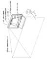
図3は、視聴者の検出位置が適正視聴範囲から外れた状況を概略的に示す。3D映像処理装置100の前方における角錐台形状の範囲が適正視聴範囲250を示しており、本例では映像表示部107の表示画面上に、適正視聴範囲250に対応する適正視聴範囲の表示画像252が表示される。そして視聴者の検出位置が適正視聴範囲250から外れていると判定された場合、前記S207にて視聴者の位置情報251が適正視聴範囲の表示画像252の外側に画像表示される。つまり位置表示画像が映像表示部107によって視覚的に表示される。画面上の適正視聴範囲の表示画像252と視聴者の位置情報251を視聴者が見ることにより、現在の視聴位置を確認できる。よって、視聴者の検出位置が適正視聴範囲から外れている場合には、現在の視聴位置と適正視聴範囲との位置関係を表示画面から把握できる。視聴者は適正視聴範囲内に移動して、3D映像効果をもつ映像を確実に視聴できる。 FIG. 3 schematically shows a situation where the viewer's detection position is out of the proper viewing range. The range of the truncated pyramid shape in front of the 3D image processing apparatus 100 indicates the appropriate viewing range 250. In this example, the display image 252 of the appropriate viewing range corresponding to the appropriate viewing range 250 is displayed on the display screen of the
[第2実施形態]
次に本発明に係る第2実施形態について説明する。第2実施形態では、シャッタ式眼鏡を使用する時分割方式の3D視聴システムへの適用例を示す。視聴者を個別に認識する認識手段を設けることにより、個々の視聴者の検出位置を識別することができる。視聴位置が適正視聴範囲外である場合、記憶されている適正視聴範囲の画像情報に対して、視聴者全員の検出位置を表す画像情報を合成した位置表示画像が作成されて表示される。[Second Embodiment]
Next, a second embodiment according to the present invention will be described. In the second embodiment, an example of application to a time-division 3D viewing system using shutter glasses is shown. By providing the recognition means for recognizing the viewer individually, the detection position of each viewer can be identified. When the viewing position is out of the proper viewing range, a position display image is created and displayed by combining image information representing the detection positions of all viewers with the stored image information in the proper viewing range.
本実施形態の前提である、シャッタ式眼鏡を使用した時分割方式の3D映像視聴について説明する。この方式では、人間の左右両眼の各々に対応して作成した画像を交互に表示し,それと同期して右眼又は左眼を、眼鏡に取り付けた液晶シャッタによって遮蔽する。視聴者は、液晶シャッタの付いた眼鏡をかけて3D映像を視聴する。つまり左眼用映像の表示時には、左眼側の液晶シャッタを透過状態にし、かつ右眼側の液晶シャッタを非透過状態にする。逆に右眼用映像の表示時には、右眼側の液晶シャッタを透過状態にし、かつ左眼側の液晶シャッタを非透過状態にする。この切り替え動作を繰り返せば、眼の残像効果によって、視聴者は両眼で視差像を同時に見ているように感じる。こうして両眼視差による立体視が実現され、これを時分割立体画像表示システムと呼ぶ。 The time-division 3D video viewing using shutter-type glasses, which is a premise of the present embodiment, will be described. In this method, images created corresponding to each of the left and right eyes of a human are alternately displayed, and the right eye or the left eye is shielded by a liquid crystal shutter attached to the glasses in synchronization with the images. The viewer views the 3D video by wearing glasses with a liquid crystal shutter. That is, when the left-eye video is displayed, the left-eye liquid crystal shutter is set in the transmissive state, and the right-eye liquid crystal shutter is set in the non-transmissive state. Conversely, when displaying the right-eye video image, the right-eye liquid crystal shutter is set to the transmissive state and the left-eye side liquid crystal shutter is set to the non-transmissive state. If this switching operation is repeated, the viewer feels as if viewing the parallax image with both eyes simultaneously due to the afterimage effect of the eyes. In this way, stereoscopic viewing based on binocular parallax is realized, and this is called a time-division stereoscopic image display system.
図4は、第2実施形態に係る3D映像処理装置の構成例を示すブロック図である。本システムは3D映像処理装置400と、シャッタ式眼鏡150を用いて構成される。以下では便宜上、2人の視聴者を例にして説明することとし、一方の視聴者が第1の眼鏡150_1を使用し、他方の視聴者が第2の眼鏡150_2を使用する場合を想定する。 FIG. 4 is a block diagram illustrating a configuration example of the 3D video processing apparatus according to the second embodiment. This system is configured using a 3D video processing device 400 and shutter
第2実施形態と第1実施形態との相違点は、位置判定部500における視聴者の位置検出方法と、眼鏡のシャッタ開閉制御と、映像出力制御部601による位置表示画像の切り替え制御である。よって以下では、これらの相違点を中心に説明し、第1実施形態で説明した構成要素と同様の構成要素については第1実施形態の場合に用いた符号と同じ符号を用いることで、それらの説明を省略する。なお、このことは後述の第3実施形態でも同様とする(図中のジャンル判別部801については第3実施形態にて説明する)。 The differences between the second embodiment and the first embodiment are the viewer position detection method in the position determination unit 500, shutter opening / closing control of the glasses, and position display image switching control by the video
各眼鏡には制御部が設けられており、装置本体内の制御部A110と区別するために、以下では、これらを制御部B(符号151_1及び152_2参照)とする。また装置本体と各眼鏡との間で情報を送受信する通信手段については、装置本体側の手段を通信部C113とし、眼鏡側の手段を通信部D(符号153_1及び153_2参照)とする。 Each eyeglass is provided with a control unit, and in order to distinguish it from the control unit A110 in the apparatus main body, hereinafter, these are referred to as a control unit B (see reference numerals 151_1 and 152_2). As for the communication means for transmitting and receiving information between the apparatus main body and each spectacle, the apparatus main body means is the communication unit C113, and the eyeglass side means is the communication unit D (see reference numerals 153_1 and 153_2).
先ず、装置本体側の構成を説明する。映像出力制御部601は、デコード部105が出力する3D映像信号と、位置表示画像作成部600が作成した位置表示画像の映像信号を受けて、時分割処理を行う。つまり映像出力制御部601は、眼鏡150の制御に同期して、左眼用映像、右眼用映像、位置表示画像を切り替えて映像表示部107に表示させる。左眼用映像の表示時には、左眼用映像が映像表示部107に表示され、かつ通信部C113を介して眼鏡の左シャッタを開放する指示が行われる。また、右眼用映像の表示時には、右眼用映像が映像表示部107に表示され、かつ通信部C113に対して眼鏡の右シャッタを開放する指示が行われる。これにより、映像表示部107は、眼鏡150_1,2を用いて3D映像と位置表示画像の視認が可能な映像を表示する。映像表示部107に表示される映像に合わせて、映像出力制御部601は、眼鏡150_1,2のシャッタ開閉制御に必要な制御信号を生成し、通信部C113を介して眼鏡150_1,2に伝送する。 First, the configuration on the apparatus main body side will be described. The video
通信部C113は、眼鏡150_1,2に対して、識別情報を先頭に付加した信号を送り、各眼鏡より返信があるか否かを確認することで電源状態を検知する。装置本体と各眼鏡との通信では、主に眼鏡へのシャッタ制御信号が伝達される。 The communication unit C113 detects the power state by sending a signal with identification information added to the head of the glasses 150_1 and 2 and confirming whether there is a reply from each of the glasses. In communication between the apparatus main body and each spectacle, a shutter control signal is mainly transmitted to the spectacles.
次に、眼鏡の構成を説明する。なお眼鏡150_1と150_2は同じ構成を有するので、一方の眼鏡150_1だけを説明する。他方の眼鏡150_2については、符号中の「_1」を「_2」に置き換えて以下の説明を読み替えればよい。
制御部B151_1は、シャッタ部152_1のシャッタ制御と、通信部D153_1の通信制御を行う。シャッタ部152_1は、制御部B151_1から制御信号を受けて、右眼、左眼の各シャッタを独立に開閉する。
通信部D153_1は、3D映像処理装置400との通信に用いられ、主に3D映像処理装置400から伝送されるシャッタ制御信号の受信に使用される。Next, the configuration of the glasses will be described. Note that since the glasses 150_1 and 150_2 have the same configuration, only one of the glasses 150_1 will be described. For the other spectacles 150_2, “_1” in the code may be replaced with “_2” and the following description may be read.
The control unit B151_1 performs shutter control of the shutter unit 152_1 and communication control of the communication unit D153_1. The shutter unit 152_1 receives the control signal from the control unit B151_1, and opens and closes the shutters for the right eye and the left eye independently.
The communication unit D153_1 is used for communication with the 3D video processing apparatus 400, and is mainly used for receiving a shutter control signal transmitted from the 3D video processing apparatus 400.
眼鏡150_1のシャッタ制御により、眼鏡をかけた各視聴者は、映像表示部107による映像を3D映像として視聴できる。
図5の外観例に示すように、シャッタ式眼鏡は赤外線LED(発光ダイオード)154_1及び電源スイッチ155_1を備える。LED154_1は、後述する方法で眼鏡150_1を識別する際に点滅される赤外光源であり、3D映像処理装置400のカメラ部114によって認識可能である。電源スイッチ155_1は、眼鏡150_1の電源を投入し又は切断するためのON/OFFスイッチである。Through the shutter control of the glasses 150_1, each viewer wearing glasses can view the video displayed on the
As shown in the appearance example in FIG. 5, the shutter-type glasses include an infrared LED (light emitting diode) 154_1 and a power switch 155_1. The LED 154_1 is an infrared light source that flashes when the glasses 150_1 are identified by a method described later, and can be recognized by the
視聴者の位置検出時には、カメラ部114で視聴者の眼鏡150_1のLED154_1を認識することにより、その位置情報及び識別情報(個別ID)を取得する。この処理については後で詳しく説明する。
範囲情報記憶部116には、適正視聴範囲の情報が記憶されている。制御部A110は、検出部115が検出した眼鏡の位置情報と、範囲情報記憶部116に記憶された適正視聴範囲の情報との間で比較演算を行う。位置表示画像作成部600は、この比較演算の結果に基づいて眼鏡の検出位置が適正視聴範囲内にないと判定された場合、記憶されている適正視聴範囲を表す画像情報に対し、前記検出位置を表す画像情報を合成して画像データを生成する。この画像データは映像出力制御部601に伝送され、映像表示部107に位置表示画像として表示される。When the viewer's position is detected, the
The range
次に図6のフローチャートを用いて、眼鏡の位置検出及び眼鏡毎の検出位置を位置表示画像として表示する場合の制御の流れを説明する。
まずS501では、各視聴者が眼鏡150_1,2をそれぞれかけて、電源スイッチ155_1,2をON状態にすると、制御部B151_1,2が動作を開始する。通信部D153_1,2が通信処理を開始し、3D映像処理装置400に対し認証要求を行う。Next, the flow of control when the position detection of the glasses and the detection position for each pair of glasses are displayed as a position display image will be described using the flowchart of FIG.
First, in S501, when each viewer puts on the glasses 150_1 and 2 and turns on the power switch 155_1 and 2, the control unit B151_1 and 2 starts operating. The communication units D153_1 and 2 start communication processing and make an authentication request to the 3D video processing device 400.
S502では、各眼鏡150_1,2からの認証要求を通信部C113が受信する。これを制御部A110に通知することで、3D映像処理装置400は各眼鏡150_1,2の電源スイッチがON状態になったと分かる。制御部A110は、各眼鏡から同時に通信要求が来た場合、一方の通信のみを受け付け、他方を待機させる。 In S502, the communication unit C113 receives an authentication request from each of the eyeglasses 150_1 and 150_1. By notifying this to the control unit A110, the 3D image processing apparatus 400 can know that the power switches of the glasses 150_1 and 2 are turned on. When a communication request is simultaneously received from each pair of glasses, the control unit A110 accepts only one communication and waits for the other.
S503では、機器認証のため、3D映像処理装置400が眼鏡150_1,2に対し、シャッタ式眼鏡を識別するための識別情報の通知要求を行う。この要求を受けた各眼鏡150_1,2は、固有の識別情報を、通信部D153_1,2から3D映像処理装置400の通信部C113に通知する。通信部C113は識別情報を受けた後で、制御部A110と検出部115が各眼鏡150_1,2の識別情報を管理する。識別情報としては、例えば、シャッタ式眼鏡のモデル名及びシリアルナンバなどが使用されるが、複数のシャッタ式眼鏡をそれぞれ識別できる情報であれば如何なる情報でも構わない。 In S503, for device authentication, the 3D video processing device 400 requests the glasses 150_1 and 2 for notification of identification information for identifying the shutter glasses. Receiving this request, each of the glasses 150_1 and 2 notifies the unique identification information from the communication unit D153_1 and 2 to the communication unit C113 of the 3D video processing device 400. After the communication unit C113 receives the identification information, the control unit A110 and the
S504にて3D映像処理装置400の通信部C113は、各眼鏡150_1,2に対して、各々LEDの点滅パターンが異なる識別用信号を送信する。この識別用信号を通信部D153_1,2がそれぞれ受け取り、制御部B151_1,2が識別用の各点滅パターンを管理する(S505)。各眼鏡150_1,2は、通信部D153_1,2を介して、LEDの点滅パターンの信号を3D映像処理装置400の通信部C113に送信する。通信部C113からの通知を受けて制御部A110は、前記識別情報と識別用の点滅パターンの判別及び管理を行う。これにより、3D映像処理装置400は、各眼鏡を特定する識別情報毎にその位置を知ることが可能となる。 In S504, the communication unit C113 of the 3D video processing apparatus 400 transmits identification signals having different LED blinking patterns to the glasses 150_1 and 2 respectively. The communication units D153_1 and 2 receive the identification signals, respectively, and the control units B151_1 and 2 manage each blinking pattern for identification (S505). The eyeglasses 150_1 and 2 transmit the LED blinking pattern signal to the communication unit C113 of the 3D video processing device 400 via the communication units D153_1 and D2. Upon receiving the notification from the communication unit C113, the control unit A110 determines and manages the identification information and the blinking pattern for identification. As a result, the 3D video processing apparatus 400 can know the position of each piece of identification information that specifies each eyeglass.
S506では、視聴者が装着した各眼鏡150_1,2の位置検出が開始する。カメラ部114を用いて各視聴者を撮影する処理が行われ、撮像データが検出部115に送出される。位置情報の取得は、シャッタ式眼鏡の左右に設けられた赤外線LEDの中点を原点として行われる。前後方向の位置検出では、3D映像処理装置400の通信部C113と各眼鏡150_1,2の通信部D153_1,2との間で行う赤外線通信を利用する。赤外線LEDの分布をモニタリングして位置測定を行うことにより、S503で付与された識別情報及び視聴者の位置情報が検出される。 In S506, the position detection of the glasses 150_1 and 2 worn by the viewer is started. A process of photographing each viewer is performed using the
第2実施形態では、シャッタ式眼鏡の左右に赤外線LEDを設けた例で説明するが、通信用LEDを使用して位置検出を行うことも可能である。また、シャッタ式眼鏡のシャッタ制御信号の伝送には、赤外線通信を利用できるが、超広帯域無線(UWB)通信で実現しても良い。例えば、超広帯域無線(UWB)通信を用いた測距技術を用いて、3D映像処理装置400と眼鏡との間の距離を測定する方法が挙げられる。 In the second embodiment, an example in which infrared LEDs are provided on the left and right sides of the shutter-type glasses will be described, but position detection can also be performed using communication LEDs. In addition, although infrared communication can be used for transmission of the shutter control signal of the shutter-type glasses, it may be realized by ultra wideband wireless (UWB) communication. For example, there is a method of measuring the distance between the 3D video processing apparatus 400 and the glasses using a distance measurement technique using ultra wideband wireless (UWB) communication.
S507では、S506で検出した視聴者の眼鏡150の位置情報と、範囲情報記憶部116に予め記憶されている適正視聴範囲の情報との間の比較演算を制御部A110が行う。そしてS508では、S507での比較演算の結果に基づき、視聴者の検出位置が適正視聴範囲から外れているか否かが判定される。その結果、視聴者の検出位置が適正視聴範囲外である場合、S509に進み、該検出位置が適正視聴範囲内である場合にはS511へ進む。 In S507, the control unit A110 performs a comparison operation between the position information of the
S509では、S508にて適正視聴範囲外と判定した視聴者の検出位置が、適正視聴範囲から外れている時間を制御部A110が計測する。そして計測時間が基準時間、例えば3秒以上であると判定された場合、S510に進むが、そうでない場合にはS511に進む。なお、基準時間の設定については固定値とするか、又は可変値として値を予め変更できるようにしてもよい。 In S509, the control unit A110 measures the time during which the detected position of the viewer determined to be out of the proper viewing range in S508 is out of the proper viewing range. If it is determined that the measurement time is a reference time, for example, 3 seconds or more, the process proceeds to S510. If not, the process proceeds to S511. The setting of the reference time may be a fixed value or may be changed in advance as a variable value.
S510では、映像出力制御部601が時分割表示のフレームレートでの切替制御を行い、適正視聴範囲外にある眼鏡150のシャッタ制御に関して、3D映像表示から位置表示画像へと切り替えるように制御する。位置表示画像作成部600は、記憶されている適正視聴範囲を表す画像情報に対し、視聴者の眼鏡の検出位置を表す画像情報を合成した画像データを生成し、位置表示画像のデータを映像出力制御部601に送出する。これにより映像表示部107に位置表示画像が表示される。そしてS512に進む。 In S510, the video
S511では映像表示部107が3D映像信号に従って映像を表示し、S512に進む。ここで制御部A110は、眼鏡の電源がOFF状態となったか否かについて検出する。その結果、各眼鏡の電源がOFF状態でない場合、S506へ戻って処理が続行されるが、眼鏡の電源OFF状態が検出された場合、S513に進む。なおS506へ戻る制御動作については、例えば、5Hz程度にて電源状態が連続的に取得される。 In S511, the
S513では、眼鏡との通信が途絶えたことを通信部C113が検出し、その旨を制御部A110に通知する。これにより、3D映像処理装置400は眼鏡の電源がOFF状態になったと判断できる。次のS514では、電源状態の検出結果(OFF検出)に基づいて、電源の切断を検出したシャッタ式眼鏡に対応する識別情報を制御部A110が破棄する。これにより制御部A110及び検出部115により管理される識別情報の数が1つ減ることになる。位置表示画像作成部117は、電源のOFF検出結果に基づいて、電源の切断を検出したシャッタ式眼鏡に対応する、画像生成を行う。 In S513, the communication unit C113 detects that communication with the glasses has been interrupted, and notifies the control unit A110 of that fact. Thereby, the 3D video processing apparatus 400 can determine that the power of the glasses has been turned off. In next S514, based on the detection result (OFF detection) of the power supply state, the control unit A110 discards the identification information corresponding to the shutter-type glasses that detected the power-off. As a result, the number of pieces of identification information managed by the control unit A110 and the
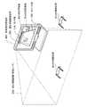
図7は、眼鏡150_1をかけた第1の視聴者が適正視聴範囲250内に位置し、眼鏡150_2をかけた第2の視聴者が適正視聴範囲250から外れた位置にいる状況を一例として示す。前記S510にて説明したように、位置表示画像作成部600は、適正視聴範囲250の画像情報と各視聴者の位置情報を含む位置表示画像のデータを作成し、位置表示画像を映像表示部107が表示する。位置表示画像には、適正視聴範囲の表示画像252と、眼鏡150_1の識別情報ID#1によって特定される第1の視聴者の位置情報と、眼鏡150_2の識別情報ID#2で特定される第2の視聴者の位置情報が表示される。つまりこの表示例では、視聴者すべてのシャッタ式眼鏡のIDが表示される。第2の視聴者は位置表示画像を見ることで自分の現在位置が適正視聴範囲外にあることを把握できる。 FIG. 7 shows, as an example, a situation where the first viewer wearing spectacles 150_1 is located within the appropriate viewing range 250 and the second viewer wearing spectacles 150_2 is located outside the proper viewing range 250. . As described in S510, the position display
図7の例では、すべての視聴者の位置を画面に表示させたが、適正視聴範囲外の視聴者の位置情報だけを画面に表示してもよい。例えば、第2の視聴者が適正視聴範囲外に位置する場合、その眼鏡150_2の識別情報ID#2のみが適正視聴範囲の表示画像252の外に表示され、適正視聴範囲内に位置する第1の視聴者の眼鏡150_1の識別情報ID#1は画面に表示されない。この場合、位置表示画像作成部600が作成する位置表示画像では、適正視聴範囲250の画像情報に対し、適正視聴範囲外にある眼鏡150_2の検出位置情報が識別情報ID#2とともに合成される。生成された画像データは映像出力制御部601に伝送され、映像表示部107によって位置表示画像が表示される。 In the example of FIG. 7, the positions of all viewers are displayed on the screen, but only the position information of viewers outside the appropriate viewing range may be displayed on the screen. For example, when the second viewer is located outside the proper viewing range, only the identification
図8は、通信部C113から通信部D153_1,2への通信によって行われるシャッタ制御に係るタイミングチャートの一例を示す。以下では眼鏡150_1(識別情報ID#1)を装着した第1の視聴者が適正視聴範囲内で3D映像を視聴し、眼鏡150_2(識別情報ID#2)を装着した第2の視聴者が適正視聴範囲外で位置表示画像を見る場合について説明する。図中の表示画像は、1フレーム目と2フレーム目の画像を示す。「左1」は1フレーム目の左眼用画像を示し、「右1」は1フレーム目の右眼用画像を示し、「位置表示1」は1フレーム目の位置表示画像を示す。同様に「左2」は2フレーム目の左眼用画像を示し、「右2」は2フレーム目の右眼用画像を示し、「位置表示2」は2フレーム目の位置表示画像を示す。シャッタ制御信号は、表示画像の先頭にて眼鏡の識別情報ID#1、ID#2を指定して、左右のシャッタのうち、どちらのシャッタを開けるかを制御する信号である。例えば、「ID#1左」はID#1で特定される眼鏡の左眼用シャッタの開放を意味する。また「ID#2左右」はID#2で特定される眼鏡の左眼用シャッタ及び右眼用シャッタをともに開放することを意味する。 FIG. 8 shows an example of a timing chart relating to shutter control performed by communication from the communication unit C113 to the communication unit D153_1,2. In the following, the first viewer wearing spectacles 150_1 (identification information ID # 1) views 3D video within the appropriate viewing range, and the second viewer wearing spectacles 150_2 (identification information ID # 2) is appropriate. A case where a position display image is viewed outside the viewing range will be described. The display images in the figure show the first and second frame images. “
眼鏡150_1,2は、先頭位置に付加された識別情報ID#1又はID#2に従ってシャッタ動作を行う。表示画像のフレームレートは、例えば180Hzとされる。眼鏡150_1を用いて第1の視聴者が見る画像について説明すると、「左1」表示の時には、「ID#1左」であり、これは左眼用シャッタを開ける制御指示である。よって左眼用シャッタが開放され、右眼用シャッタは閉じられるので、第1の視聴者は左眼用映像「左1」を見ることができる。そして「右1」表示の時には、「ID#1右」であり、これは右眼用シャッタを開ける制御指示である。よって右眼用シャッタが開放され、左眼用シャッタは閉じられるので、第1の視聴者は右眼用映像「右1」を見ることができる。2フレーム目以降も同様の制御が行われ、第1の視聴者は3D映像の視聴を享受できる。 The glasses 150_1 and 2 perform a shutter operation according to the identification
一方、眼鏡150_2を装着した第2の視聴者が見る映像は位置表示画像だけである。つまり、「位置表示1」の時には、シャッタ制御信号の指示が「ID#2左右」であり、これは左右両方のシャッタを開ける制御指示である。両眼ともにシャッタが開放され、第2の視聴者は「位置表示1」、つまり位置表示画像を見ることができる。2フレーム目以降も同様に第2の視聴者には位置表示画像だけが提示される。このように眼鏡の識別情報を指定し、個々の視聴者に対して位置表示画像を見るように個別のシャッタ制御が可能となり、視聴者に適正視聴範囲から外れた位置にいることを知らせて注意を促すことができる。 On the other hand, the image viewed by the second viewer wearing the glasses 150_2 is only the position display image. That is, at the time of “
以上のように、第2実施形態によれば、適正視聴範囲から外れた場所にいる視聴者のシャッタ式眼鏡に対し、時分割制御によって位置表示画像を表示することができる。その際、3D映像処理装置400の3D映像表示は維持されるため、適正視聴範囲内にいる他の視聴者は、位置表示画像の表示によって視聴中断を余儀なくされることがなく、3D映像を継続して視聴できる。 As described above, according to the second embodiment, it is possible to display a position display image by time-sharing control on the shutter-type glasses of the viewer who is out of the proper viewing range. At that time, since the 3D video display of the 3D video processing device 400 is maintained, other viewers within the appropriate viewing range continue to view the 3D video without being forced to interrupt the viewing by displaying the position display image. You can watch it.
[第3実施形態]
次に、本発明の第3実施形態について説明する。第3実施形態では、放送コンテンツに含まれるメタデータより構成される電子番組表を用いて所定の操作を行う技術を利用する。前記実施形態との相違点は、視聴対象とするコンテツに応じて、3D視聴に係る適正視聴範囲を変更して、視聴領域を動的に制御する手段を講じたことである。よって、以下では相違点を中心に説明し、前記実施形態と同様の事項については説明を省略する。[Third embodiment]
Next, a third embodiment of the present invention will be described. In the third embodiment, a technique for performing a predetermined operation using an electronic program guide composed of metadata included in broadcast content is used. The difference from the above embodiment is that a means for dynamically controlling the viewing area is provided by changing the appropriate viewing range related to 3D viewing according to the content to be viewed. Therefore, below, it demonstrates centering around a difference and abbreviate | omits description about the matter similar to the said embodiment.
図1や図4にて、チューナ部103はアンテナ部102を介して放送波を受信して、受信信号をデコード部105に供給する。デコード部105は、供給された信号のうち、EPG(電子番組表)情報を取得する。位置判定部300,500内に設けられたジャンル判別部801はEPG情報に基づいて、コンテンツのジャンルを判別する。 1 and 4, the
図9のフローチャートを用いて、ジャンル判別部801の判定結果に基づき視聴ジャンルに対応した適正視聴範囲に切り替える、ジャンル別視聴範囲制御の流れを説明する。
まずS850にてジャンル判別部801は、EPG情報を取得し、コンテンツのジャンルを示す情報を特定する。次のS851ではジャンル判別部801が、例えばスポーツ、ニュースや映画のアクション、アニメーションなどを判別する。ジャンル判別部801はジャンルを判別し、この判別したジャンルに対応する範囲情報記憶部116内の適正視聴範囲の情報を指定して位置表示画像作成部117に設定する。The flow of genre-specific viewing range control for switching to the appropriate viewing range corresponding to the viewing genre based on the determination result of the
First, in S850, the
S852では、S851で判別されたジャンル毎に適正視聴範囲の設定が行われる。つまり範囲情報記憶部116には、各ジャンル用の適正視聴範囲を示す情報が記憶されており、ジャンル判別部801が判別したジャンルの情報に基づいて適正視聴範囲の領域変更が行われる。例えば、あるジャンルでは適正視聴範囲を狭めることで、視聴者が3D映像をさらに見やすい場所へと誘導することができる。検出部115による視聴者の検出位置又はシャッタ式眼鏡の検出位置と、範囲情報記憶部116に記憶された領域変更後の適正視聴範囲との間の比較演算を制御部A110が行う。こうしてジャンル別視聴範囲の変更制御が可能となる。すなわち視聴対象となるコンテンツ毎に適正視聴範囲が変更され、視聴者は最適な視聴範囲で3D映像を視聴できる。 In S852, an appropriate viewing range is set for each genre determined in S851. That is, the range
100 3D映像処理装置
106 映像出力制御部
107 映像表示部
110 制御部A
113 通信部C
114 カメラ部
115 検出部
116 範囲情報記憶部
117 位置表示画像作成部
150_1,2 眼鏡
151_1,2 制御部B
152_1,2 シャッタ部
153_1,2 通信部D
154_1,2 LED
155_1,2 電源スイッチ
250 適正視聴範囲(視聴エリア)
251 視聴者の位置情報
252 適正視聴範囲の表示画像
300 位置判定部
400 3D映像処理装置
500 位置判定部
600 位置表示画像作成部
601 映像出力制御部
801 ジャンル判別部DESCRIPTION OF SYMBOLS 100 3D
113 Communication part C
114
152_1, shutter part 153_1, communication part D
154_1,2 LED
155_1, 2 Power switch 250 Appropriate viewing range (viewing area)
251 Viewer position information 252 Appropriate viewing range display image 300 Position determination unit 400 3D video processing device 500
Claims (8)
Translated fromJapanese前記視聴位置を検出する位置検出手段と、
前記視聴範囲を示す情報を記憶している範囲情報記憶手段と、
前記位置検出手段が検出した視聴位置を表す画像情報、及び前記視聴範囲を表す画像情報を含む位置表示画像を生成して表示手段に表示させるように制御する制御手段と、を備えることを特徴とする3D映像処理装置。A 3D video processing apparatus having a function of presenting a positional relationship between a viewing position and a viewing range where 3D video can be viewed,
Position detecting means for detecting the viewing position;
Range information storage means for storing information indicating the viewing range;
Control means for controlling to generate and display on the display means a position display image including image information representing the viewing position detected by the position detection means and image information representing the viewing range. 3D video processing device.
前記位置検出手段は前記眼鏡の位置を前記視聴位置として検出し、
前記眼鏡はその識別情報を示す信号を前記制御手段に通知する通信手段を有することを特徴とする、請求項1記載の3D映像処理装置。The display means includes glasses having shutter means and video display means for displaying 3D video,
The position detecting means detects the position of the glasses as the viewing position;
The 3D image processing apparatus according to claim 1, wherein the glasses include a communication unit that notifies the control unit of a signal indicating the identification information.
前記制御手段は、前記位置検出手段によって検出した第1の眼鏡の位置が前記視聴範囲内であると判定した場合、前記通信手段によって制御信号を前記第1の眼鏡に送信し、そのシャッタ手段の時分割制御により3D映像を提示するように制御し、前記位置検出手段によって検出した第2の眼鏡の位置が前記視聴範囲外であると判定した場合、前記通信手段によって制御信号を前記第2の眼鏡に送信し、そのシャッタ手段の時分割制御により前記位置表示画像を提示するように制御することを特徴とする、請求項3又は4に記載の3D映像処理装置。Communication means for transmitting a control signal to the shutter means of the glasses;
When the control means determines that the position of the first glasses detected by the position detection means is within the viewing range, the control means transmits a control signal to the first glasses by the communication means, and the shutter means Control is performed to present 3D video by time-division control, and when it is determined that the position of the second glasses detected by the position detection unit is outside the viewing range, a control signal is transmitted by the communication unit to the second signal. 5. The 3D video processing apparatus according to claim 3, wherein the position display image is controlled to be transmitted to the glasses and presented by time-sharing control of the shutter unit. 6.
前記制御手段は、前記判別手段が判別したジャンルに応じて前記視聴範囲を示す情報を変更するように制御することを特徴とする、請求項1から6のいずれか1項記載の3D映像処理装置。The content to be viewed is further provided with a determination means for determining the genre,
The 3D video processing apparatus according to claim 1, wherein the control unit performs control so as to change information indicating the viewing range according to the genre determined by the determination unit. .
前記視聴位置を検出する位置検出ステップと、
前記位置検出ステップで検出した視聴位置を表す画像情報、及び予め記憶された前記視聴範囲を表す画像情報を含む位置表示画像を生成するステップと、を有することを特徴とする3D映像処理装置の制御方法。A control method for a 3D video processing apparatus having a function of presenting a positional relationship between a viewing position and a viewing range in which 3D video can be viewed,
A position detecting step for detecting the viewing position;
And a step of generating a position display image including image information representing the viewing position detected in the position detecting step and image information representing the viewing range stored in advance. Method.
Priority Applications (1)
| Application Number | Priority Date | Filing Date | Title |
|---|---|---|---|
| JP2009194029AJP5404246B2 (en) | 2009-08-25 | 2009-08-25 | 3D image processing apparatus and control method thereof |
Applications Claiming Priority (1)
| Application Number | Priority Date | Filing Date | Title |
|---|---|---|---|
| JP2009194029AJP5404246B2 (en) | 2009-08-25 | 2009-08-25 | 3D image processing apparatus and control method thereof |
Publications (3)
| Publication Number | Publication Date |
|---|---|
| JP2011049630Atrue JP2011049630A (en) | 2011-03-10 |
| JP2011049630A5 JP2011049630A5 (en) | 2012-10-04 |
| JP5404246B2 JP5404246B2 (en) | 2014-01-29 |
Family
ID=43835573
Family Applications (1)
| Application Number | Title | Priority Date | Filing Date |
|---|---|---|---|
| JP2009194029AExpired - Fee RelatedJP5404246B2 (en) | 2009-08-25 | 2009-08-25 | 3D image processing apparatus and control method thereof |
Country Status (1)
| Country | Link |
|---|---|
| JP (1) | JP5404246B2 (en) |
Cited By (27)
| Publication number | Priority date | Publication date | Assignee | Title |
|---|---|---|---|---|
| JP2011133832A (en)* | 2009-12-25 | 2011-07-07 | Toshiba Corp | Image display device, method, and position determination device |
| JP2012008584A (en)* | 2011-08-05 | 2012-01-12 | Toshiba Corp | Image display device, notification method and position judgement device |
| CN102685537A (en)* | 2011-03-16 | 2012-09-19 | 精工爱普生株式会社 | Display device, display system, and method for controlling display device |
| WO2012124418A1 (en)* | 2011-03-17 | 2012-09-20 | ソニー株式会社 | Display device and display method and |
| CN102724533A (en)* | 2011-03-28 | 2012-10-10 | 卡西欧计算机株式会社 | Display system, display device and display assistance device |
| JP2012199902A (en)* | 2011-03-21 | 2012-10-18 | Samsung Electronics Co Ltd | Display apparatus, control method thereof, shutter glasses, and control method thereof |
| JP2012213086A (en)* | 2011-03-31 | 2012-11-01 | Sharp Corp | Stereoscopic image display device and stereoscopic glasses |
| JP2012212954A (en)* | 2011-03-30 | 2012-11-01 | Casio Comput Co Ltd | Image presentation system and image presentation method |
| JP2012217072A (en)* | 2011-04-01 | 2012-11-08 | Seiko Epson Corp | Projector and projection method |
| JP2012222427A (en)* | 2011-04-05 | 2012-11-12 | Sumitomo Electric Ind Ltd | Video playback device |
| JP2012227858A (en)* | 2011-04-22 | 2012-11-15 | Seiko Epson Corp | Image display system, image display device, 3d glasses, and image display method |
| WO2013001697A1 (en)* | 2011-06-27 | 2013-01-03 | パナソニック株式会社 | Video processing device and video processing method |
| KR20130015772A (en)* | 2011-08-05 | 2013-02-14 | 엘지디스플레이 주식회사 | Display apparatus for displaying three dimensional picture and driving method for the same |
| CN102970553A (en)* | 2011-08-31 | 2013-03-13 | 株式会社东芝 | Three-dimensional image processing apparatus and three-dimensional image processing method |
| CN102970560A (en)* | 2011-08-30 | 2013-03-13 | 株式会社东芝 | Three-dimensional image processing apparatus and three-dimensional image processing method |
| JP2013051623A (en)* | 2011-08-31 | 2013-03-14 | Toshiba Corp | Video processing apparatus and video processing method |
| JP2013055681A (en)* | 2012-10-30 | 2013-03-21 | Toshiba Corp | Video processing apparatus and video processing method |
| JP2013059094A (en)* | 2012-11-09 | 2013-03-28 | Toshiba Corp | Three-dimensional image processing apparatus and three-dimensional image processing method |
| CN103096103A (en)* | 2011-11-04 | 2013-05-08 | 株式会社东芝 | Video processing device and video processing method |
| CN103167311A (en)* | 2011-12-09 | 2013-06-19 | 株式会社东芝 | Video processing device, video processing method, and recording medium |
| KR101288120B1 (en)* | 2011-11-23 | 2013-07-19 | 한국과학기술연구원 | 3D display system to display optimal viewing area for observer |
| JPWO2013132886A1 (en)* | 2012-03-07 | 2015-07-30 | ソニー株式会社 | Information processing apparatus, information processing method, and program |
| US9176991B2 (en) | 2013-11-21 | 2015-11-03 | International Business Machines Corporation | Storing photographic metadata for scene reproduction |
| US9179141B2 (en) | 2011-05-30 | 2015-11-03 | Kabushiki Kaisha Toshiba | Three-dimensional image display apparatus and viewing position check method |
| KR20170107719A (en)* | 2016-03-16 | 2017-09-26 | 엘지전자 주식회사 | Head mounted display and, the controlling method thereof |
| US9986140B2 (en) | 2013-11-21 | 2018-05-29 | International Business Machines Corporation | Utilizing metadata for automated photographic setup |
| CN115243027A (en)* | 2022-07-21 | 2022-10-25 | 杭州吉沁文化创意有限公司 | Three-dimensional display method, storage medium and device of curved surface two-dimensional screen |
Families Citing this family (1)
| Publication number | Priority date | Publication date | Assignee | Title |
|---|---|---|---|---|
| CN104702939B (en)* | 2015-03-17 | 2017-09-15 | 京东方科技集团股份有限公司 | Image processing system, method, the method for determining position and display system |
Citations (3)
| Publication number | Priority date | Publication date | Assignee | Title |
|---|---|---|---|---|
| JPH10271536A (en)* | 1997-03-24 | 1998-10-09 | Sanyo Electric Co Ltd | Stereoscopic video display device |
| JPH11341518A (en)* | 1998-05-26 | 1999-12-10 | Nippon Telegr & Teleph Corp <Ntt> | Multi-view simultaneous observation type horizontally arranged stereoscopic image display system |
| JP2009250987A (en)* | 2008-04-01 | 2009-10-29 | Casio Hitachi Mobile Communications Co Ltd | Image display apparatus and program |
- 2009
- 2009-08-25JPJP2009194029Apatent/JP5404246B2/ennot_activeExpired - Fee Related
Patent Citations (3)
| Publication number | Priority date | Publication date | Assignee | Title |
|---|---|---|---|---|
| JPH10271536A (en)* | 1997-03-24 | 1998-10-09 | Sanyo Electric Co Ltd | Stereoscopic video display device |
| JPH11341518A (en)* | 1998-05-26 | 1999-12-10 | Nippon Telegr & Teleph Corp <Ntt> | Multi-view simultaneous observation type horizontally arranged stereoscopic image display system |
| JP2009250987A (en)* | 2008-04-01 | 2009-10-29 | Casio Hitachi Mobile Communications Co Ltd | Image display apparatus and program |
Cited By (36)
| Publication number | Priority date | Publication date | Assignee | Title |
|---|---|---|---|---|
| JP2011133832A (en)* | 2009-12-25 | 2011-07-07 | Toshiba Corp | Image display device, method, and position determination device |
| CN102685537A (en)* | 2011-03-16 | 2012-09-19 | 精工爱普生株式会社 | Display device, display system, and method for controlling display device |
| JP2012195728A (en)* | 2011-03-16 | 2012-10-11 | Seiko Epson Corp | Display device, display system, and method for controlling display device |
| EP2552119A4 (en)* | 2011-03-17 | 2014-02-12 | Sony Corp | Display device and display method and |
| WO2012124418A1 (en)* | 2011-03-17 | 2012-09-20 | ソニー株式会社 | Display device and display method and |
| JP2012195894A (en)* | 2011-03-17 | 2012-10-11 | Sony Corp | Display device and display method |
| CN103081486A (en)* | 2011-03-17 | 2013-05-01 | 索尼公司 | Display device and display method and |
| JP2012199902A (en)* | 2011-03-21 | 2012-10-18 | Samsung Electronics Co Ltd | Display apparatus, control method thereof, shutter glasses, and control method thereof |
| CN102724533A (en)* | 2011-03-28 | 2012-10-10 | 卡西欧计算机株式会社 | Display system, display device and display assistance device |
| US8994797B2 (en) | 2011-03-28 | 2015-03-31 | Casio Computer Co., Ltd. | Display system, display device and display assistance device |
| JP2012212954A (en)* | 2011-03-30 | 2012-11-01 | Casio Comput Co Ltd | Image presentation system and image presentation method |
| JP2012213086A (en)* | 2011-03-31 | 2012-11-01 | Sharp Corp | Stereoscopic image display device and stereoscopic glasses |
| JP2012217072A (en)* | 2011-04-01 | 2012-11-08 | Seiko Epson Corp | Projector and projection method |
| JP2012222427A (en)* | 2011-04-05 | 2012-11-12 | Sumitomo Electric Ind Ltd | Video playback device |
| JP2012227858A (en)* | 2011-04-22 | 2012-11-15 | Seiko Epson Corp | Image display system, image display device, 3d glasses, and image display method |
| US9179141B2 (en) | 2011-05-30 | 2015-11-03 | Kabushiki Kaisha Toshiba | Three-dimensional image display apparatus and viewing position check method |
| WO2013001697A1 (en)* | 2011-06-27 | 2013-01-03 | パナソニック株式会社 | Video processing device and video processing method |
| KR20130015772A (en)* | 2011-08-05 | 2013-02-14 | 엘지디스플레이 주식회사 | Display apparatus for displaying three dimensional picture and driving method for the same |
| KR101922086B1 (en)* | 2011-08-05 | 2018-11-27 | 엘지디스플레이 주식회사 | Display Apparatus For Displaying Three Dimensional Picture And Driving Method For The Same |
| JP2012008584A (en)* | 2011-08-05 | 2012-01-12 | Toshiba Corp | Image display device, notification method and position judgement device |
| CN102970560A (en)* | 2011-08-30 | 2013-03-13 | 株式会社东芝 | Three-dimensional image processing apparatus and three-dimensional image processing method |
| JP2013051623A (en)* | 2011-08-31 | 2013-03-14 | Toshiba Corp | Video processing apparatus and video processing method |
| CN102970553A (en)* | 2011-08-31 | 2013-03-13 | 株式会社东芝 | Three-dimensional image processing apparatus and three-dimensional image processing method |
| JP2013051602A (en)* | 2011-08-31 | 2013-03-14 | Toshiba Corp | Electronic device and control method for electronic device |
| CN103096103A (en)* | 2011-11-04 | 2013-05-08 | 株式会社东芝 | Video processing device and video processing method |
| KR101288120B1 (en)* | 2011-11-23 | 2013-07-19 | 한국과학기술연구원 | 3D display system to display optimal viewing area for observer |
| CN103167311A (en)* | 2011-12-09 | 2013-06-19 | 株式会社东芝 | Video processing device, video processing method, and recording medium |
| JPWO2013132886A1 (en)* | 2012-03-07 | 2015-07-30 | ソニー株式会社 | Information processing apparatus, information processing method, and program |
| JP2013055681A (en)* | 2012-10-30 | 2013-03-21 | Toshiba Corp | Video processing apparatus and video processing method |
| JP2013059094A (en)* | 2012-11-09 | 2013-03-28 | Toshiba Corp | Three-dimensional image processing apparatus and three-dimensional image processing method |
| US9176991B2 (en) | 2013-11-21 | 2015-11-03 | International Business Machines Corporation | Storing photographic metadata for scene reproduction |
| US9986140B2 (en) | 2013-11-21 | 2018-05-29 | International Business Machines Corporation | Utilizing metadata for automated photographic setup |
| US10623620B2 (en) | 2013-11-21 | 2020-04-14 | International Business Machines Corporation | Utilizing metadata for automated photographic setup |
| KR20170107719A (en)* | 2016-03-16 | 2017-09-26 | 엘지전자 주식회사 | Head mounted display and, the controlling method thereof |
| KR102606116B1 (en) | 2016-03-16 | 2023-11-24 | 엘지전자 주식회사 | Head mounted display and, the controlling method thereof |
| CN115243027A (en)* | 2022-07-21 | 2022-10-25 | 杭州吉沁文化创意有限公司 | Three-dimensional display method, storage medium and device of curved surface two-dimensional screen |
Also Published As
| Publication number | Publication date |
|---|---|
| JP5404246B2 (en) | 2014-01-29 |
Similar Documents
| Publication | Publication Date | Title |
|---|---|---|
| JP5404246B2 (en) | 3D image processing apparatus and control method thereof | |
| US8684531B2 (en) | Stereoscopic display device projecting parallax image and adjusting amount of parallax | |
| US20110221746A1 (en) | 3d eyeglasses, method for driving 3d eyeglasses and system for providing 3d image | |
| JP5448594B2 (en) | Stereoscopic image display control device and control method of stereoscopic video display control device | |
| JP2011193460A (en) | Method for adjusting 3d-image quality, 3d-display apparatus, 3d-glasses, and system for providing 3d-image | |
| JP2012015774A (en) | Stereoscopic image processing device and stereoscopic image imaging method | |
| US20130286163A1 (en) | 3d glasses | |
| JP2013516882A (en) | Apparatus and method for recognizing stereoscopic glasses, and method for controlling display of a stereoscopic video stream | |
| US20120127572A1 (en) | Stereoscopic display apparatus and method | |
| KR101309705B1 (en) | Glasses and 3D image display system employing the same | |
| KR20120006742A (en) | A user interface output method of a display device for outputting three-dimensional content and a display device employing the method | |
| JP5132804B1 (en) | Video processing apparatus and video processing method | |
| US9124880B2 (en) | Method and apparatus for stereoscopic image display | |
| CA2788996C (en) | Stereoscopic display system based on glasses using photochromatic lenses | |
| CN103167311A (en) | Video processing device, video processing method, and recording medium | |
| KR20120125274A (en) | System and method for controlling the display of a stereoscopic video stream | |
| JP2011250368A (en) | Three-dimensional display device, display control circuit, and display method | |
| JP5474530B2 (en) | Stereoscopic image display device | |
| KR20120059947A (en) | 3D glasses and method for controlling 3D glasses thereof | |
| KR20110136326A (en) | 3D stereoscopic rendering system reflecting horizontal angle information of 3D stereoscopic glasses | |
| JP5433763B2 (en) | Video processing apparatus and video processing method | |
| GB2481094A (en) | 3D display with automatic switching between 2D and 3D display modes | |
| US20120081523A1 (en) | 2d/3d compatible display system which automatically switches operational modes | |
| KR20140074022A (en) | Method and apparatus for display of selected contents and multi-view 3D images | |
| KR20120009897A (en) | A user interface output method of a display device for outputting three-dimensional content and a display device employing the method |
Legal Events
| Date | Code | Title | Description |
|---|---|---|---|
| A521 | Request for written amendment filed | Free format text:JAPANESE INTERMEDIATE CODE: A523 Effective date:20120820 | |
| A621 | Written request for application examination | Free format text:JAPANESE INTERMEDIATE CODE: A621 Effective date:20120820 | |
| A977 | Report on retrieval | Free format text:JAPANESE INTERMEDIATE CODE: A971007 Effective date:20130404 | |
| A131 | Notification of reasons for refusal | Free format text:JAPANESE INTERMEDIATE CODE: A131 Effective date:20130409 | |
| TRDD | Decision of grant or rejection written | ||
| A01 | Written decision to grant a patent or to grant a registration (utility model) | Free format text:JAPANESE INTERMEDIATE CODE: A01 Effective date:20131001 | |
| A61 | First payment of annual fees (during grant procedure) | Free format text:JAPANESE INTERMEDIATE CODE: A61 Effective date:20131029 | |
| R151 | Written notification of patent or utility model registration | Ref document number:5404246 Country of ref document:JP Free format text:JAPANESE INTERMEDIATE CODE: R151 | |
| LAPS | Cancellation because of no payment of annual fees |