JP2011047774A - Proximity detection device and proximity detection method - Google Patents
Proximity detection device and proximity detection methodDownload PDFInfo
- Publication number
- JP2011047774A JP2011047774AJP2009195970AJP2009195970AJP2011047774AJP 2011047774 AJP2011047774 AJP 2011047774AJP 2009195970 AJP2009195970 AJP 2009195970AJP 2009195970 AJP2009195970 AJP 2009195970AJP 2011047774 AJP2011047774 AJP 2011047774A
- Authority
- JP
- Japan
- Prior art keywords
- matrix
- calculation
- electrode
- transmission
- current
- Prior art date
- Legal status (The legal status is an assumption and is not a legal conclusion. Google has not performed a legal analysis and makes no representation as to the accuracy of the status listed.)
- Pending
Links
Images


Classifications
- G—PHYSICS
- G06—COMPUTING OR CALCULATING; COUNTING
- G06F—ELECTRIC DIGITAL DATA PROCESSING
- G06F3/00—Input arrangements for transferring data to be processed into a form capable of being handled by the computer; Output arrangements for transferring data from processing unit to output unit, e.g. interface arrangements
- G06F3/01—Input arrangements or combined input and output arrangements for interaction between user and computer
- G06F3/03—Arrangements for converting the position or the displacement of a member into a coded form
- G06F3/041—Digitisers, e.g. for touch screens or touch pads, characterised by the transducing means
- G06F3/0416—Control or interface arrangements specially adapted for digitisers
- G06F3/04166—Details of scanning methods, e.g. sampling time, grouping of sub areas or time sharing with display driving
- G—PHYSICS
- G06—COMPUTING OR CALCULATING; COUNTING
- G06F—ELECTRIC DIGITAL DATA PROCESSING
- G06F3/00—Input arrangements for transferring data to be processed into a form capable of being handled by the computer; Output arrangements for transferring data from processing unit to output unit, e.g. interface arrangements
- G06F3/01—Input arrangements or combined input and output arrangements for interaction between user and computer
- G06F3/03—Arrangements for converting the position or the displacement of a member into a coded form
- G06F3/041—Digitisers, e.g. for touch screens or touch pads, characterised by the transducing means
- G06F3/044—Digitisers, e.g. for touch screens or touch pads, characterised by the transducing means by capacitive means
- G06F3/0446—Digitisers, e.g. for touch screens or touch pads, characterised by the transducing means by capacitive means using a grid-like structure of electrodes in at least two directions, e.g. using row and column electrodes
Landscapes
- Engineering & Computer Science (AREA)
- General Engineering & Computer Science (AREA)
- Theoretical Computer Science (AREA)
- Human Computer Interaction (AREA)
- Physics & Mathematics (AREA)
- General Physics & Mathematics (AREA)
- Measurement Of Length, Angles, Or The Like Using Electric Or Magnetic Means (AREA)
- Position Input By Displaying (AREA)
Abstract
Description
Translated fromJapanese本発明は、2次元座標に対応して配置された複数の電極の各交点の静電容量の変化により、人の指などの物体の接近や位置を検出する近接検出装置に関する。 The present invention relates to a proximity detection device that detects the approach and position of an object such as a human finger by a change in electrostatic capacitance at each intersection of a plurality of electrodes arranged corresponding to two-dimensional coordinates.
近傍に配置される2つの電極間に人の指などの物体が接近すると、電極間の静電容量が変化することが知られている。この原理を検出領域の2次元座標に対応して配置された複数の電極の各交点の静電容量の検出に応用した静電タッチセンサなどの近接検出装置が開示され、一部が実用化されている(例えば、特許文献1参照。)。 It is known that when an object such as a human finger approaches between two electrodes arranged in the vicinity, the capacitance between the electrodes changes. A proximity detection device such as an electrostatic touch sensor, in which this principle is applied to detection of capacitance at each intersection of a plurality of electrodes arranged corresponding to the two-dimensional coordinates of a detection region, is disclosed and partly put into practical use. (For example, refer to Patent Document 1).
このような従来の近接検出装置の一例について、図8を基に説明する。 An example of such a conventional proximity detector will be described with reference to FIG.
図8の例では、支持手段1の検出領域2に縦方向の座標に対応する送信電極3と横方向の座標に対応する受信電極4が互いに直交して配置されている。送信電極3には、線順次駆動手段35から選択的に1つの電極ごと、線順次に周期的な交流電圧が印加される。この交流電圧は、送信電極3と受信電極4との交点の静電結合により、受信電極4に伝達される。電流測定手段6では、仮想接地された受信電極4に流れる電流から対応する各交点の静電結合に応じた値を検出して、検出した値を近接演算手段8に出力する。ここで、微弱な交流電流を累積して求めるために、送信電極3に順次選択的に印加される周期的な交流電圧に同期して累積コンデンサをスイッチ切り換えしたり、復調波形を畳み込むことにより累積していた。 In the example of FIG. 8, the
しかし、図8に示す例の場合には、線順次駆動のため、検出の効率に課題があった。この課題を解決するために、図2に示すようなマルチライン駆動の近接検出装置が開示されている。図2の例では、支持手段1の検出領域2に縦方向の座標に対応する送信電極3と横方向の座標に対応する受信電極4が互いに直交して配置されている。送信電極3には、マルチライン駆動手段5から同時に複数の送信電極3に異なるパターンの波形が印加される。この波形は、送信電極3と受信電極4との交点の静電結合により、受信電極4に伝達される。電流測定手段6では、仮想接地された受信電極4に流れ込む電流を測定する。 However, the example shown in FIG. 8 has a problem in detection efficiency because of line sequential driving. In order to solve this problem, a proximity detection device of multi-line drive as shown in FIG. 2 is disclosed. In the example of FIG. 2, the
ここで、演算手段10bは相関演算手段17と近接演算手段8とにより構成され、相関演算手段17で送信電極3に印加したパターンと電流測定手段6の測定値との相関から各送電極と受信電極4との交点の静電容量あるいはそれらの変化を求め、近接演算手段8で加重平均などにより接近する物体の位置を演算する(例えば、特許文献2参照。)。 Here, the calculation means 10b is composed of a correlation calculation means 17 and a proximity calculation means 8, and each transmission electrode and reception are determined from the correlation between the pattern applied to the
さらに、送信電極3に印加するパターンによりキャリアを変調して駆動することにより、充放電の回数を大幅に増やして効率良く検出する方法も開示されている(例えば、特許文献3参照。)。 Furthermore, a method is also disclosed in which the carrier is modulated and driven by a pattern applied to the
以上に示した従来のマルチライン駆動による近接検出装置では、相関演算手段の演算量が多く、検出速度を速くするためには高速の演算器が必要であることが課題となっていた。また、送信電極に印加するパターンが完全に直交していない場合には、相関演算結果にクロストークを発生することが課題となっていた。 The conventional multiline drive proximity detection apparatus described above has a problem that the amount of calculation of the correlation calculation means is large, and a high-speed calculator is required to increase the detection speed. Further, when the patterns applied to the transmission electrodes are not completely orthogonal, it has been a problem to generate crosstalk in the correlation calculation result.
そこで、本発明では、これらの課題を解決するために、以下の装置及び方法を提供する。 Therefore, the present invention provides the following apparatus and method in order to solve these problems.
つまり、送信電極に印加するパターン及び検出パネルの特性を行列として捉え、電流測定手段の測定値に送信電極に印加するパターンの逆行列を掛けることにより、送信電極に印加するパターンが完全に直交していない場合でも、クロストークのない検出パネルの各交点の静電容量に対応した値を得ることができる近接検出装置及びその方法である。 In other words, the pattern applied to the transmission electrode and the characteristics of the detection panel are regarded as a matrix, and the pattern applied to the transmission electrode is completely orthogonal by multiplying the measured value of the current measuring means by the inverse matrix of the pattern applied to the transmission electrode. A proximity detection apparatus and method that can obtain a value corresponding to the capacitance of each intersection of detection panels without crosstalk even when the detection panel is not cross talk.
また、逆行列の演算の途中結果を記憶する記憶手段を設け、その記憶手段を活用して演算を高速に行うことを可能にするための送信電極に印加するパターンを用いることにより、高速の演算器を用いることなく高速に検出することのできる近接検出装置及びその方法である。 In addition, a storage means is provided for storing intermediate results of the inverse matrix calculation, and a high-speed calculation is performed by using a pattern applied to the transmission electrode to enable the calculation to be performed at high speed using the storage means. A proximity detection apparatus and method capable of detecting at high speed without using a detector.
本発明は、上記課題を解決するために、以下の発明を開示する。 In order to solve the above problems, the present invention discloses the following invention.
第1の発明は、物体の接近判定或いは接近位置を求める近接検出装置であって、支持手段上の検出領域における2つの次元のうち一方の次元に対応する複数の送信電極と、他方の1つの次元に対応する受信電極と、送信電極の少なくとも二つ以上の電極に周期的な交流電圧を同時に印加するマルチライン駆動手段と、受信電極からの電流あるいは蓄積された電荷量を送信電極への駆動に同期して測定する電流測定手段と、電流測定手段で測定した電流値あるいは蓄積された電荷量を送信電極と受信電極の各交点の静電容量に対応した値に変換し検出領域への物体の接近判定或いは接近位置を求める演算手段と、マルチライン駆動手段と電流測定手段と演算手段のステータス及びシーケンスを管理する制御手段とにより構成され、演算手段は、電流測定手段で測定した電流値あるいは蓄積された電荷量を線形演算し送信電極と受信電極の各交点の静電容量に対応した値に変換する線形演算手段と、線形演算手段の出力から検出領域への物体の接近判定或いは接近位置を求める近接演算手段とにより構成され、線形演算手段は、演算の途中結果を記憶し複数回読み出される記憶手段を有すること。 A first invention is a proximity detection device for determining an approach of an object or obtaining an approach position, wherein a plurality of transmission electrodes corresponding to one of two dimensions in a detection region on a support means and one of the other A receiving electrode corresponding to the dimension, a multi-line driving means for simultaneously applying a periodic AC voltage to at least two electrodes of the transmitting electrode, and driving the current from the receiving electrode or the accumulated charge amount to the transmitting electrode. Current measurement means for measuring in synchronization with the current, and the current value measured by the current measurement means or the accumulated charge amount is converted into a value corresponding to the capacitance at each intersection of the transmission electrode and the reception electrode, and the object to the detection region The calculation means for obtaining the approach determination or approach position, the multi-line drive means, the current measurement means, and the control means for managing the status and sequence of the calculation means, the calculation means, Linear calculation means for linearly calculating the current value measured by the current measurement means or the accumulated charge amount and converting it to a value corresponding to the capacitance at each intersection of the transmission electrode and the reception electrode, and the detection region from the output of the linear calculation means It is comprised with the proximity calculation means which calculates | requires the approach of an object to the object, or calculates | requires an approach position, and a linear calculation means has a memory means which memorize | stores the intermediate result of a calculation and is read out several times.
第2の発明は、上記第1の発明において、線形演算手段が、高速アダマール変換もしくは高速アダマール変換と同様の変換を行うこと。 According to a second invention, in the first invention, the linear operation means performs the same conversion as the fast Hadamard transform or the fast Hadamard transform.
第3の発明は、上記第1および2の発明において、マルチライン駆動手段が駆動するパターンはアダマール行列の逆行列またはアダマール行列の部分行列の逆行列であること。 According to a third invention, in the first and second inventions, the pattern driven by the multiline driving means is an inverse matrix of a Hadamard matrix or an inverse matrix of a submatrix of a Hadamard matrix.
第4の発明は、上記第2および3の発明において、マルチライン駆動手段が駆動するパターンを決定する送信電圧行列が、シルベスターの生成法によるアダマール行列もしくはシルベスターの生成法によるアダマール行列の行または列を入換えた行列もしくはそれらの部分行列の特定の行をマイナス1倍したものであり、線形演算手段における高速アダマール変換もしくは高速アダマール変換と同様の変換においてマイナス1倍した行に対応する電流測定手段の測定値をマイナス1倍したことと同等の演算を行うこと。 According to a fourth invention, in the second and third inventions, the transmission voltage matrix for determining the pattern driven by the multiline driving means is a Hadamard matrix by the Sylvester generation method or a Hadamard matrix row or column by the Sylvester generation method. Current measurement means corresponding to a row obtained by subtracting a specific row of a matrix obtained by replacing the sub-matrix or a sub-matrix of the sub-matrix and subtracting 1 by one in a fast Hadamard transformation or a transformation similar to a fast Hadamard transformation in a linear operation means Perform the same calculation as when the measured value of minus is multiplied by 1.
第5の発明は、上記第2及び第3の発明において、マルチライン駆動手段が駆動するパターンを決定する送信電圧行列が、シルベスターの生成法によるアダマール行列もしくはシルベスターの生成法によるアダマール行列の行または列を入換えた行列もしくはそれらの部分行列の特定の列をマイナス1倍したものであり、線形演算手段における高速アダマール変換もしくは高速アダマール変換と同様の変換においてマイナス1倍した列に対応する変換値をマイナス1倍したことと同等の演算を行うこと。 According to a fifth invention, in the second and third inventions, the transmission voltage matrix for determining the pattern driven by the multiline driving means is a Hadamard matrix by the Sylvester generation method or a Hadamard matrix row by the Sylvester generation method or A matrix obtained by substituting a column or a specific column of those sub-matrices minus one, and a transformation value corresponding to a column that is minus one in a fast Hadamard transform or a transformation similar to the fast Hadamard transform in the linear arithmetic means Perform the same calculation as minus one.
第6の発明は、上記第1から5のいずれかに記載の発明において、上記近接検出装置に従った入力装置を備えている情報機器であること。 A sixth invention is an information device comprising the input device according to the proximity detection device according to any one of the first to fifth inventions.
第7の発明は、上記第6の発明において、情報機器が携帯電話からなること。 In a seventh aspect based on the sixth aspect, the information device comprises a mobile phone.
第8の発明は、上記第6の発明において、情報機器がマルチメディアプレイヤーからなること。 In an eighth aspect based on the sixth aspect, the information device comprises a multimedia player.
第9の発明は、上記第6の発明において、情報機器がナビゲーションシステムからなること。 In a ninth aspect based on the sixth aspect, the information device comprises a navigation system.
第10の発明は、上記第6の発明において、情報機器がコンピュータからなること。 In a tenth aspect based on the sixth aspect, the information device comprises a computer.
本発明によれば、同時に複数の送信電極に交流電圧を印加することにより、比較的低い電圧で駆動したり高速で動作したりしてもクロストークのない良好な検出をすることが出来る近接検出装置及びその方法を実現することが出来る。電源電圧と検出速度と交流電圧の周波数が同じ場合には、ノイズの影響を小さくすることのできる近接検出装置及びその方法を実現することができる。 According to the present invention, by applying an AC voltage to a plurality of transmission electrodes at the same time, proximity detection can be performed without crosstalk even when driven at a relatively low voltage or operated at a high speed. An apparatus and its method can be realized. When the power supply voltage, the detection speed, and the AC voltage have the same frequency, it is possible to realize a proximity detection apparatus and method that can reduce the influence of noise.
以下、本発明を実施するための形態について、図面を参照して詳細に説明する。 Hereinafter, embodiments for carrying out the present invention will be described in detail with reference to the drawings.
本発明の好適な実施例を、図1を基に説明する。 A preferred embodiment of the present invention will be described with reference to FIG.
本発明による近接検出装置は図1において、支持手段1上の検出領域2における2次元座標の一方の次元に対応する送信電極3ともう一方の次元に対応する受信電極4を互いに導通しないように絶縁層を介して設け、送信電極3の複数の電極に同時に周期的な交流電圧を印加するマルチライン駆動手段5と、送信電極3と受信電極4の交点の静電結合に対応して変化する受信電極4からの電流の大きさを送信電極3への駆動に同期して測定する電流測定手段6と、電流測定手段6で測定した電流値から送信電極3と受信電極4の各交点の静電結合に対応した値に変換した値あるいはその推移により検出領域2への物体の接近判定と接近位置を求める演算手段10aと、全体のステータス及びシーケンスを管理する制御手段9aとにより構成した。演算手段10aは電流測定手段6で測定した電流値から送信電極3と受信電極4の各交点の静電結合に対応した値に変換する線形演算手段7と、線形演算手段7からの各交点の静電結合に対応した値あるいはその推移により検出領域2への物体の接近判定と接近位置を求める近接演算手段8とにより構成される。 In FIG. 1, the proximity detection apparatus according to the present invention prevents the
本発明の特徴を、図1及び図5を参考にして、また従来例との違いを基にして説明する。 The features of the present invention will be described with reference to FIGS. 1 and 5 and based on the difference from the conventional example.
(1)演算手段10aまたは演算工程30の相違。従来の相関演算手段17から本発明の線形演算手段7へ置き換えた。従来、各送信電極3と受信電極4のそれぞれの交点の静電容量あるいはその変化を求めるために、送信電極3に印加したパターンと電流測定手段6で測定した電流値との相関を演算していたが、本発明では送信電極3に印加したパターンと検出パネルの特性を行列として捉え、電流測定手段6の測定値に送信電極3に印加するパターンの逆行列を掛けることにより、各交点の静電容量に対応した値を得る点が異なる。 (1) Difference in the calculation means 10a or the
(2)制御手段9aにランダムなインターバルを加えるインターバル発生手段41の追加。本発明では、ノイズの影響をランダムにする目的で送信電極3より出力するタイミングにランダムなインターバルを必要に応じて挿入する。それによりマルチライン駆動においてノイズの影響をランダムにすることができる。 (2) Addition of an interval generating means 41 for adding a random interval to the control means 9a. In the present invention, a random interval is inserted as needed at the timing of output from the
(3)制御手段9aにパワーセーブモード切替手段42の追加。本発明ではマルチライン駆動であるため、指の近接位置を正確に求めるためには1周期の測定として送信電極3の数と同じ回数各送信電極3を駆動する必要がある。しかし、検出領域2上に人体の指などの検出対象が近接していない状態等正確な近接位置を知る必要がない場合には1周期の測定として送信電極3の数より少ない回数で各送信電極3を駆動することで電力消費を抑えることが実現できる。そのため、近接演算手段8により指などの検出対象の近接の有無を判断、いわゆる近接判定し、パワーセーブモード切替手段42で指などの検出対象が近接していない場合には1周期の測定で送信電極3の数より少ない回数で各送信電極3を駆動するモード、いわゆるパワーセーブモードに切り替え、指などの検出対象が近接している場合には1周期の測定で送信電極3の数だけ各送信電極3を駆動するモードに切り替える。前述のパワーセーブモードでは各送信電極3の数より少ない回数で駆動するのであれば電力消費を抑えることが期待できるが、1回のみの駆動である場合がもっとも好ましい。この場合では検出領域2の検出位置は特定できないが全ての検出領域2での検出の有無の情報を得ることができる。パワーセーブモードにおいて指などの検出対象が検出された場合にはパワーセーブモードから1周期の測定で送信電極3の数だけ各送信電極3を駆動するモードに切り替えることで消費電力を抑えられる。 (3) Addition of power save mode switching means 42 to the control means 9a. In the present invention, since the multi-line drive is used, it is necessary to drive each
これより本発明による近接検出装置およびその方法を構成する各手段および各工程について、詳細に説明する。 Hereafter, each means and each process which comprise the proximity detection apparatus and its method by this invention are demonstrated in detail.
支持手段1の検出領域2には、例えば縦方向の座標に対応する送信電極3と横方向の座標に対応する受信電極4を互いに直交して配置した。これらの電極は導電性であり、送信電極3と受信電極4の交点では絶縁層により両電極が直流的に絶縁されて電気的に静電結合している。 In the
ここで、説明の便宜上、送信電極3は対応する座標値が1からNまでの自然数で表される位置ごとに存在し、対応する送信電極3は添え字nによって区別されるものとする。同様に、受信電極4は対応する座標値が1からMまでの自然数で表される位置ごとに存在し、対応する受信電極4は添え字mによって区別されるものとする。 Here, for convenience of explanation, it is assumed that the
また、送信電極3と受信電極4の配置は前述した実施例のように略直交した平面に限定されるものではなく、斜交座標や角度と原点からの距離からなる円座標など2次元座標に対応するものであればどのように配置しても良い。
マルチライン駆動手段5は、駆動パターンを示す送信電圧行列T(t,n)に対応した周期的な交流電圧を複数の送信電極3に印加する。送信電圧行列Tの添え字tは行列の行番号でt回目の駆動であることに対応し、添え字nは列番号でn番目の送信電極3に対応する。例えば、2回目の駆動で送信電極3に印加する交流電圧は、T(2,3)に対応する。In addition, the arrangement of the
The multiline driving means 5 applies a periodic alternating voltage corresponding to the transmission voltage matrix T (t, n) indicating the driving pattern to the plurality of
同時に印加される複数の交流電圧波形は、ある同一の交流電圧波形に送信電圧行列の対応する要素T(t,n)をそれぞれ係数として掛けた交流電圧波形になるようにした。従って、送信電圧行列の要素がマイナスの場合は逆相の交流電圧波形を印加することを意味する。この際、直流成分が重畳していても、影響はない。 A plurality of AC voltage waveforms applied simultaneously are AC voltage waveforms obtained by multiplying a certain AC voltage waveform by a corresponding element T (t, n) of the transmission voltage matrix as a coefficient. Therefore, when the element of the transmission voltage matrix is negative, it means that an AC voltage waveform having a reverse phase is applied. At this time, even if the DC component is superimposed, there is no influence.
ここで、送信電圧行列T(t,n)は、逆行列が存在する正方行列である正則行列とする。そのため添え字tは1から送信電極数Nまでの自然数となる。従来の線順次駆動の場合には、送信電圧行列T(t,n)は、単位行列I(t,n)に一致する。 Here, the transmission voltage matrix T (t, n) is a regular matrix that is a square matrix having an inverse matrix. Therefore, the subscript t is a natural number from 1 to the number N of transmission electrodes. In the case of conventional line sequential driving, the transmission voltage matrix T (t, n) matches the unit matrix I (t, n).
また、周期的な交流電圧とは、例えば矩形波や正弦波や三角波などである。ただし、各電極はそれ自体に抵抗値と静電容量をもっているために高い周波数は減衰し、交点は直列の静電容量のために低い周波数が減衰する。これらを勘案して、送信電極3に印加する電圧の周波数は、減衰の小さい周波数にすることが望ましい。 The periodic AC voltage is, for example, a rectangular wave, a sine wave, a triangular wave, or the like. However, each electrode has its own resistance value and capacitance, so that the high frequency is attenuated, and the intersection is attenuated at low frequency because of the series capacitance. Considering these, it is desirable that the frequency of the voltage applied to the
さらに構成を簡単にするために、例えば送信電圧行列T(t,n)の各要素を、例えば1か0か−1のいずれかにするなど、0を除く各要素の絶対値が同じ値になるような正則行列にする。周期的な交流電圧を矩形波にすると、例えば図3に示すような簡単な論理回路でマルチライン駆動手段5を構成することが出来る。 In order to further simplify the configuration, for example, each element of the transmission voltage matrix T (t, n) is set to one, 0, or −1, for example, the absolute value of each element except 0 is the same value. A regular matrix such that When the periodic AC voltage is a rectangular wave, the multiline driving means 5 can be configured with a simple logic circuit as shown in FIG. 3, for example.
ここで図3の構成の説明をする。図1の制御手段9a内にあるタイミング信号発生手段40より送信電圧行列の行番号tに対応したタイミング信号を図3の送信電圧行列参照手段12に出力するとともに、同期して矩形波を発生するためのタイミング信号を矩形波発生手段11に出力する。矩形波発生手段11は前述のタイミング信号を元に複数サイクルの矩形波を生成し、インバータ16を経由する配線とインバータ16を経由しない配線の二種をもってN個存在する選択手段13へ接続される。選択手段13は、送信電圧行列の対応する要素の値が1の場合はインバータ16を経由しない配線を選択し、送信電圧行列の対応する要素の値が−1の場合はインバータ16を経由する配線を選択し、送信電圧行列の対応する要素の値が0の場合には0Vの配線を選択するようにした。選択手段13で選択された信号は、必要に応じて遅延時間調整手段14を経由し、駆動波形として出力される。前述の遅延時間調整手段14は直列に抵抗が接続され、抵抗を介した後に定電圧電源に接続されたコンデンサの他方の端子が接続されている。遅延時間調整手段14の出力には、インピーダンスを下げるために必要に応じてバッファを設けても良い。 Here, the configuration of FIG. 3 will be described. A timing signal corresponding to the row number t of the transmission voltage matrix is output from the timing signal generation means 40 in the control means 9a of FIG. 1 to the transmission voltage matrix reference means 12 of FIG. 3, and a rectangular wave is generated in synchronization. The timing signal is output to the rectangular wave generating means 11. The rectangular wave generating means 11 generates a plurality of cycles of rectangular waves based on the timing signal described above, and is connected to N selection means 13 having two types of wirings that pass through the
送信電圧行列参照手段12への送信電圧行列T(t,n)のある要素が0の場合には、その要素に対応する交流電圧波形を0Vにするために例えば選択手段13により0Vを送信電極3に接続する。他の要素においても同様のように選択手段13で選択した電圧を送信電極3に接続する。このように、送信電圧行列T(t,n)の要素により、動作させればよい。 When a certain element of the transmission voltage matrix T (t, n) to the transmission voltage matrix reference means 12 is 0, for example, the selection means 13 sets 0V to the transmission electrode in order to set the AC voltage waveform corresponding to that element to 0V. Connect to 3. Similarly, the voltage selected by the
なお、図1における受信電極4は、それ自体に抵抗値と静電容量をもっているために交流の伝達に遅延時間を生じる。図3において選択手段13の後ろにある遅延時間調整手段14は、これを微調整するためのもので、必要に応じて設ける。これは送信電極3により異なる受信電極4までの遅延時間を微調整するためのものである。つまり、電流測定手段6に遠い送信電極3に合わせるために、近い送信電極3の遅延時間を長く設定するというものである。それにより、受信電極4までに発生する遅延時間のばらつきの影響が解消され、同時期に電流測定手段6へ伝達されることが期待できる。 The receiving
このn番目の送信電極3に印加された周期的な交流電圧は、n番目の送信電極3とm番目の受信電極4との交点の静電結合を介して、m番目の受信電極4に伝達される。検出面の汚れなどの影響があると、接近した物体自体のインピーダンスが高いため、接近した物体を介しての電界により送信電極3と受信電極4の間の電界が増えて、送信電極3と受信電極4の間の静電結合は増加し、受信電極4に流れる受信電流も大きくなる。逆に検出対象の人の指など比較的インピーダンスの低い物体が接近した場合には、送信電極3からの交流電界を吸収する作用の方が強いために、送信電極3と受信電極4の間の静電結合は減少し、受信電極4に流れる受信電流は小さくなる。従って、汚れと人の指などの検出対象は、容易に区別することができる。 The periodic AC voltage applied to the
ここで、受信電極4は、検出対象の交点近傍以外に物体が接近しても影響がないようにするために、接地あるいは仮想接地などにより電圧の変動が抑えられている。このため、受信電極4への伝達は、電圧と言うよりはむしろ電流である。つまり、選択された送信電極3とある受信電極4との交点には、静電結合により交流電界が発生するために、受信電極4に受信電流が流れるのである。そこで、物体が接近した交点では交流電界が変化するために、受信電極4に流れる受信電流が変化する。 Here, in order to prevent the
電流測定手段6では、マルチライン駆動手段5により送信電極3に送信電圧行列T(t,n)に対応した交流電圧波形が印加される毎に、m番目の受信電極4に流れる受信電流を測定して、例えばデルタシグマ型のAD変換器等によりデジタル値に変換し、対応する受信電流行列R(t,m)の値を更新して線形演算手段7に出力する。ここでの添え字tは行列の行番号でマルチライン駆動手段5でのt回目の駆動による電流であることを示し、添え字mは列番号で受信電極4の番号に対応する。 The current measuring means 6 measures the received current flowing through the
ここで、各交点の静電容量の値は通常1pF程度の微小な値であり、受信電極4に流れる受信電流やその変化も微弱である。そのため、受信電極4に流れる受信電流を検出するために、送信電極3から印加される複数の周期による電流を累積して検出する。しかし、受信電極4に流れる受信電流は交流であるため、単純に累積してしまうと累積値がゼロになってしまう。これを回避するために、従来の線順次駆動の場合と同様な手法を用いることが可能である。つまり、交流電流の位相に同期した累積をするという事である。例えば、送信電極3に印加される周期的な交流電圧に同期して累積コンデンサをスイッチ切り換えする方法は特許文献1により開示されている。また、送信電極3に印加される周期的な交流電圧に同期して復調波形を畳み込むことにより累積する方法も他の文献により開示されている。但し、送信電圧行列の値によっては、受信する電流値は負の値になる場合もある。この場合にも受信回路が飽和しないように配慮をする必要がある。具体的な方法として線形演算手段7における、例えば基準電圧や電源電圧などについて、飽和しないような値に設定や調整をするということである。 Here, the value of the capacitance at each intersection is usually a minute value of about 1 pF, and the reception current flowing through the
また電流測定手段6において、検出対象の物体が接近していない場合の測定値に近い値をオフセットとして差し引くようにすると、物体の接近による測定値の変化をより正確に測定することが出来る。この際、検出対象の物体が接近していない場合の測定値は、送信電圧行列T(t,n)の影響を大きく受ける。そのため、添え字tに対応して異なる値をオフセットとして差し引くようにした。さらに、検出面の汚れ等の影響がある場合などには、m番目の受信電極4ごとに異なる値をオフセットとして差し引くようにすると良い。 If the current measuring means 6 subtracts a value close to the measured value when the object to be detected is not approaching as an offset, the change in the measured value due to the approach of the object can be measured more accurately. At this time, the measured value when the object to be detected is not approaching is greatly affected by the transmission voltage matrix T (t, n). Therefore, a different value corresponding to the subscript t is subtracted as an offset. Furthermore, when there is an influence such as contamination on the detection surface, it is preferable to subtract a different value for each m-
マルチライン駆動を行った場合に測定される受信電流行列R(t,m)の値は、数1に示すように、送信電圧行列T(t,n)と交点結合行列P(n,m)との行列の積によって表される。ここで、交点結合行列P(n,m)とは、2次元の座標に対応した電極の各交点の静電結合の強さに対応するもので、送信電圧行列が単位行列の線順次駆動を行った場合に得られるであろう受信電流行列の値を想定したものである。なお、ここでの添え字nは行列の行番号でn番目の送信電極3に対応し、添え字mは列番号でm番目の受信電極4に対応する。 The values of the received current matrix R (t, m) measured when multiline driving is performed are as follows. The transmission voltage matrix T (t, n) and the intersection coupling matrix P (n, m) And is represented by the product of the matrix. Here, the intersection coupling matrix P (n, m) corresponds to the strength of electrostatic coupling at each intersection of the electrodes corresponding to the two-dimensional coordinates, and the transmission voltage matrix performs line sequential driving of the unit matrix. It assumes the value of the received current matrix that would be obtained if it was performed. Here, the subscript n corresponds to the

何故ならば、静電結合による電流は線形であるために加法定理が成り立つからである。例えば、n1番目の送信電極3に1Vの交流電圧を印加した場合にm番目の受信電極4へ流れ込む受信電流をR(n1,m)とし、n2番目の送信電極3に1Vの交流電圧を印加した場合にm番目の受信電極4へ流れ込むる受信電流をR(n2,m)とする。n1番目の送信電極3に2V,n2番目の送信電極3に3Vの交流電圧を同時に印加した場合には、R(n1,m)を2倍し、R(n2,m)を3倍して加算した電流がm番目の受信電極4に流れる。 This is because the addition theorem holds because the current due to electrostatic coupling is linear. For example, when an AC voltage of 1V is applied to the
したがって、線形演算手段7では、数2に示すように電流測定手段6からの受信電流行列R(t,m)に送信電圧行列T(t,n)の逆行列を左から掛ける。これにより、線順次駆動を行った場合に流れるであろう交点結合行列P(n,m)に変換する。送信電圧行列は正則行列のため、逆行列は必ず存在する。数2は、数1の両辺に送信電圧行列T(t,n)の逆行列を左から掛けて、右辺と左辺を入れ換えたものである。 Therefore, the linear calculation means 7 multiplies the reception current matrix R (t, m) from the current measurement means 6 by the inverse matrix of the transmission voltage matrix T (t, n) from the left as shown in
但し、ここでの送信電圧行列T(t,n)の逆行列は、都度演算する必要はなく、通常予め演算されたものを使用すれば良い。 However, the inverse matrix of the transmission voltage matrix T (t, n) here does not need to be calculated each time, and a normally calculated one may be used.
また、線形演算手段7の演算は必ずしも行列の掛け算を行う必要はなく、送信電圧行列T(t,n)の逆行列の要素の値が0になる項については演算の必要がないし、要素の値が1または−1に同一の係数を掛けた値の場合には単純な加減算を行えば良い。つまり、送信電圧行列T(t,n)の逆行列の全要素に同一の係数を掛けてから数2の演算を行うようにしても良い。こうすることにより、小数の要素をすべて整数にすれば、演算が簡単になるからである。特に0を除くすべての要素の絶対値が同一の値の場合などには、係数倍によりすべての要素を1か0か−1にすることができるため、簡単な加減算のみにすることができる。係数倍しても、近接演算手段8では、絶対値でなく相対値で近接演算するため、演算の結果には殆ど影響がないという特徴があるため、各要素を整数になるよう係数倍することは有益である。以降の数式の説明においても、逆行列の演算等により生じる係数についても特に問題とする必要はない。 Further, the calculation of the linear calculation means 7 does not necessarily need to perform matrix multiplication, and it is not necessary to calculate the term in which the element value of the inverse matrix of the transmission voltage matrix T (t, n) is 0. If the value is 1 or −1 multiplied by the same coefficient, simple addition / subtraction may be performed. That is, the calculation of
なお、線形演算手段7では、図1に示すように、演算の途中結果を記憶する記憶手段15を設け、一旦演算した途中結果を記憶し、記憶した値を複数回読み出して活用することにより、同じ演算を重複して繰り返し行わないようにすることが出来る。
こうして、線形演算手段7での演算量を減らして、演算時間を短くすることが出来る。例えば、送信電圧行列にアダマール行列を用いる場合には、高速アダマール変換を行う。As shown in FIG. 1, the linear calculation means 7 is provided with a storage means 15 for storing the intermediate result of the operation, stores the intermediate result once calculated, and reads and uses the stored value a plurality of times. It is possible to avoid repeating the same operation repeatedly.
Thus, the calculation amount in the linear calculation means 7 can be reduced and the calculation time can be shortened. For example, when a Hadamard matrix is used as the transmission voltage matrix, fast Hadamard transformation is performed.
その他の送信電圧行列の場合の線形演算の高速化については、後に詳細に説明する。 The speeding up of the linear operation in the case of other transmission voltage matrices will be described in detail later.
なお、本発明における演算の途中結果とは、送信電圧行列に対応して電流測定手段6で測定した受信電流の値から送信電極3と受信電極4との各交点の静電容量に対応した値を求める際に、一時的に記憶される値でのことである。従って、この演算の途中結果は、送信電圧行列と受信電流の値に依存したものである。本発明においては、特に繰り返して同じ演算をしないようにして線形演算の演算量を削減することを意図したものである。そして、一度記憶された値は複数回読み出されて再利用される特徴がある。また、線形演算の基になる受信電流の値及び線形演算の結果である送信電極3と受信電極4の各交点の静電容量に対応した値は、演算の途中結果として含まないものとする。 The intermediate result of the calculation in the present invention is a value corresponding to the capacitance at each intersection of the
送信電圧行列の値から送信電極3と受信電極4の各交点の静電容量に対応した値を求める際には、通常各交点の静電容量に対応した値を個別に演算する。しかし、本発明においては、別の交点の静電容量に対応した値を演算する際にも部分的に全く同じ演算をすることがあることに着目して、演算途中結果を記憶して複数回読み出す。以上により、演算の重複を無くして演算量を少なくして、線形演算に要する時間と消費電力を削減を実現する。 When the value corresponding to the capacitance at each intersection of the
線形演算手段7の演算は、論理回路、プロセッサやアナログ回路等により実現することができる。 The calculation of the linear calculation means 7 can be realized by a logic circuit, a processor, an analog circuit, or the like.
近接演算手段8は、線形演算手段7で求めた2次元の座標に対応した電極の各交点の静電結合に依存した電流値として、線順次駆動を行った場合に流れるであろう交点結合行列P(n,m)あるいはその推移から、検出対象の物体の接近と位置を演算する。 The proximity calculation means 8 is an intersection coupling matrix that will flow when line-sequential driving is performed as a current value depending on the electrostatic coupling of each intersection of the electrodes corresponding to the two-dimensional coordinates obtained by the linear calculation means 7. The approach and position of the object to be detected are calculated from P (n, m) or its transition.
制御手段9aは、全体動作のステータス及びシーケンスを管理する。ここでいうステータスとは、例えば電流測定中などの状態を指し、シーケンスとは電流測定のONやOFFの手順などを指す。制御手段9aはタイミング信号発生手段40とインターバル発生手段41、パワーセーブモード切替手段42などにより構成した。ただし、インターバル発生手段41及びパワーセーブモード切替手段42は必要に応じて加える。 The control means 9a manages the status and sequence of the overall operation. The status here refers to, for example, a state during current measurement, and the sequence refers to an ON / OFF procedure of current measurement. The control means 9a comprises a timing signal generating means 40, an interval generating means 41, a power save mode switching means 42, and the like. However, the interval generation means 41 and the power save mode switching means 42 are added as necessary.
本発明による近接検出方法による、具体的な動作の例について、図5を基に説明する。これは駆動測定工程20で送信電圧行列のN行分の駆動と測定をまとめて行ってから演算工程30で演算を行う場合の例である。近接検出方法を開始し、駆動測定工程20では、駆動して電流を測定し受信電流行列の更新を行なう。このために、駆動測定工程20はマルチライン駆動工程26と受信電流を測定するための電流測定工程21がある。このマルチライン駆動工程26と電流測定工程21はほぼ同時に行なわれる。またマルチライン駆動工程26はマルチライン波形発生工程24と、必要に応じて遅延時間調整工程25を有する。受信電流行列の更新をt=1〜NまでN回繰り返すことで送信電圧行列全要素に対応した駆動を一通り行う。その後、演算工程30を行なう。演算工程30は線形演算工程22と近接演算工程23とにより成り立つ。線形演算工程22により駆動測定工程20で更新された受信電流行列を、線形演算を行ない、交点結合行列を更新する。そして近接演算工程23により線形演算工程22で更新された交点結合行列の値あるいはその推移から、検出対象の物体の接近や位置を検出する。この一連の工程を一定周期で繰り返すことで近接検出方法を実現する。但し、これは一例であり、例えば並列処理などにより線形演算工程22や近接演算工程23中に次の駆動測定工程20を同時に行うようにしてもよい。 An example of a specific operation by the proximity detection method according to the present invention will be described with reference to FIG. This is an example of the case where the operation is performed in the
このように、駆動測定工程20では、マルチライン駆動工程26による送信電極3への駆動を行いながら受信電極4の電流を電流測定工程21で測定し、デジタル値に変換する。この際、通常駆動の回数tが1からNに至るまでN回繰り返すことにより、送信電圧行列の全要素に対応した駆動を一通り行う。 Thus, in the
より詳細な送信電極3への駆動と受信電極4からの電流測定のタイミングの模式図を、図4に示す。 FIG. 4 shows a schematic diagram of the timing of the driving to the transmitting
図4において、駆動波形は各送信電極3の電圧波形を示したものであり、電流測定については、駆動波形に対応した交流電流を測定するタイミングを示したものである。ランダムインターバルは、ノイズの影響をランダムにするためのランダムな待ち時間の挿入で、例えば送信電極3に対応した電流を複数回測定する間に任意のインターバルを必要に応じて挿入すればよい。横軸は、これらに共通の時間軸である。駆動波形1から駆動波形6と便宜上6つの波形を図4では示しているが、これは模式的なものであり、駆動波形の数はN個存在する。例えば駆動波形1と駆動波形2で電流測定がt=4のときに、駆動波形1は立ち上がりから開始する3サイクルの短形波を印加しているのに対し、駆動波形2では極性を反転させて立下りから開始する3サイクルの短形波を印加している。また、駆動波形4の電流測定t=5の状態や、駆動波形6における電流測定t=6についてでも極性を反転させて立下りから開始する3サイクルの短形波を印加しており、それ以外では立ち上がりから開始する3サイクルの短形波を印加している。これらの極性は、送信電圧行列の各要素の値に対応したものである。 In FIG. 4, the drive waveform shows the voltage waveform of each
図4のタイミングは、後述する数13に示す行列Tを送信電圧行列として用いた場合の一例であり、送信電圧行列の値に基づいた極性で各送信電極3に順次駆動波形が印加される。この模式図では、便宜上1回の駆動における矩形波の印加を3サイクルとしているが、この限りでないことは言うまでもない。なお、送信電極3への駆動と受信電極4からの交流の電流測定は従来の線順次駆動35の場合と同様に同期が取られており、反転した駆動による電流測定値は符号が逆になる。このように駆動して測定された電流により受信電流行列の値が更新される。送信電圧行列の全要素に対応した駆動を一通り行なうことにより、受信電流行列の全要素も更新される。 The timing in FIG. 4 is an example in the case where a matrix T shown in
線形演算工程22では、電流測定工程21で更新された受信電流行列を、線形演算手段7で線形演算を行って、交点結合行列の値を更新する。この際、後に詳細に説明するように、演算の重複をさけるために、記憶手段15を活用する。 In the
近接演算工程23では、線形演算工程22で更新された交点結合行列の値あるいはその推移から、近接演算手段8により検出対象の物体の接近や位置を検出する。 In the
但し、検出対象の物体が未だ接近していない場合で正確な位置の演算をする必要がない場合などでは、必ずしも送信電圧行列の全ての行について送信電極3への駆動と受信電極4からの電流測定を行う必要はない。最低限、全ての送信電極3が駆動されるための送信電圧行列の行についてのみ駆動すれば良い。言い換えると、各列について最低1回は駆動するようにすれば良い。例えば、前述の数13に示す送信電圧行列Tを用いる場合には、t=1〜3に対応する行についてのみ駆動すれば全ての送信電極3が駆動されるし、数9に示す送信電圧行列Tを用いる場合には、いずれか1行についてのみ駆動すれば良い。つまり、送信電極3の数よりも駆動回数のほうが少ない回数で駆動する。この場合には変化のみを抽出できれば良いので線形演算工程22を省略しても良い。何故ならば、どの交点に物体が接近しても、受信電流行列の値に通常何等かの変化があるために、近接演算手段8で物体が接近したことを検出することが可能だからである。こうすることにより、物体が接近するのを待っている状態での消費電力を小さくすることができる。いわゆるパワーセーブである。例えば、後述する全ての送信電極3を同時に駆動する場合などでは、図6に示すように、送信電圧行列1行分について送信電極3への駆動と受信電極4からの電流測定を行うのみにすることも可能である。また、数13に示す送信電圧行列Tの場合には、最初の3行分の駆動により全ての送信電極3が駆動される。 However, when the object to be detected is not yet approaching and it is not necessary to calculate an accurate position, the driving to the
図6に示す手順の説明を行なう。図6では、図5とほぼ同様の工程を有している。異なる点は、駆動測定工程20での駆動測定回数である。この近接検出方法では、例えば送信電圧行列の1行分の駆動と測定を行うごとに、更新された受信電流行列を基に線形演算と近接演算をおこない、これを一定周期ごとに繰り返す近接検出方法を示したものである。これによりパワーセーブモードを実現する。 The procedure shown in FIG. 6 will be described. 6 includes almost the same steps as those in FIG. The difference is the number of drive measurements in the
以上に数1及び数2を基に説明したが、送信電圧行列T(t,n)および交点結合行列P(n,m)および受信電流行列R(t,m)の転置行列を用いて、行列の掛け算の順番を入換えても同様であることは、言うまでもない。この場合は、数3が数1に対応し、数4が数2に対応する。この演算処理は、線形演算手段7により線形演算工程22で行なわれるものである。 As described above based on
なお、以上に電流測定手段6で送信電極3の交流電圧波形と送信電極3と受信電極4との交点の静電容量に対応した交流電流を測定した場合の例を示したが、電流測定手段6では、ステップ状の電圧変化を送信電極3に印加した場合に送信電極3と受信電極4の交点の静電容量に比例して流れる電荷量に対応した値を測定しても良い。この場合には、送信電圧行列T(t,n)に対応してn番目の送信電極3の極性を含めた電圧変化をV(t,n)、交点結合行列P(n,m)に対応してn番目の送信電極3とm番目の受信電極4の交点の静電容量をC(n,m)、受信電流行列R(t,m)に対応して電流測定手段6で測定するm番目の受信電極4に流れる電荷量をQ(t,m)、電荷量を測定するための送信電極3の電圧変化の回数をlとすると、数5と数6が成り立つ。数6は線形演算手段7及び線形演算工程22により交点結合行列に対応する交点の静電容量への変換に利用される。 In addition, although the example at the time of measuring the alternating current corresponding to the electrostatic capacitance of the alternating voltage waveform of the
これらの数5と数6は、数1と数2に対応したものである。また、数5と数6についても、数7と数8に示すように、転置行列を用いて行列の掛け算の順番を入れ換えても同様であることは、言うまでもない。 These
これより、本発明の特徴である送信電圧行列T(t,n)の各要素の値と効果の関係について説明する。前述したように、送信電圧行列は、逆行列が存在する正則行列である必要がある。また、送信電圧行列T(t,n)の要素の値は、駆動回路を簡単にするためには、1か0か−1に同一の係数を掛けた値であることが望ましい。さらに、線形演算を簡単にするためには、逆行列の要素も整数に同一の係数を掛けた値、特に1か0か−1に同一の係数を掛けた値であることが望ましい。また、送信電圧行列が直交行列の場合には、効率的に電源電圧を小さくすることができる。ここでいう直交行列とは、転置行列との積が単位行列の係数倍となる行列のことである。 The relationship between the value of each element of the transmission voltage matrix T (t, n), which is a feature of the present invention, and the effect will be described. As described above, the transmission voltage matrix needs to be a regular matrix having an inverse matrix. Also, the element value of the transmission voltage matrix T (t, n) is preferably a value obtained by multiplying 1, 0, or −1 by the same coefficient in order to simplify the drive circuit. Furthermore, in order to simplify the linear operation, it is desirable that the elements of the inverse matrix are also values obtained by multiplying the integer by the same coefficient, particularly by multiplying the same coefficient by 1 or 0 or −1. Further, when the transmission voltage matrix is an orthogonal matrix, the power supply voltage can be efficiently reduced. The orthogonal matrix here is a matrix whose product with the transposed matrix is a coefficient multiple of the unit matrix.
これらの条件を満たす行列として、例えばアダマール行列が知られている。このアダマール行列とは、要素が1または−1のいずれかであり、かつ各行が互いに直交であるような正方行列である。 As a matrix satisfying these conditions, for example, a Hadamard matrix is known. This Hadamard matrix is a square matrix whose elements are either 1 or -1 and whose rows are orthogonal to each other.
第1の送信電圧行列の例として、このアダマール行列により全ての送信電極3を同時に駆動する場合について説明する。なお、説明の便宜上、ここではシルベスターの生成法による数9に示す8行8列のアダマール行列を用いる場合について説明するが、この限りではない。なお、以降の例においても便宜上比較的小さい行列でその特徴を説明するが、同様にその限りでないことは言うまでもない。 As an example of the first transmission voltage matrix, a case where all the
この場合には、従来の線順次駆動の場合と比較すると、各電極とも駆動する回数が8倍になっており、同じ電圧で駆動した場合には、駆動には8倍の消費電力が必要になる。しかし、線順次駆動を行った場合に流れるであろう交点結合行列P(n,m)を求める場合に掛け算する送信電圧行列の逆行列は各要素の大きさが8分の1になっている。この8分の1倍の演算により、ノイズの大きさも8分の1倍になる。このため、8回の駆動の合成ノイズの強さは、ノイズがランダムの場合には二乗和の平方根により求められるため、線順次駆動の場合のノイズの強さを1とすると、数10に示すように約0.35倍になる。あるいは、8回の測定値の平均によってノイズが約0.35倍になると考えても良い。このように直交行列を用いた場合には、同時に駆動する送信電極3の数の平方根の逆数に比例してノイズを減衰させることができる。 In this case, the number of times each electrode is driven is 8 times that in the case of the conventional line-sequential driving, and when driving at the same voltage, the driving requires 8 times the power consumption. Become. However, the inverse matrix of the transmission voltage matrix to be multiplied when obtaining the intersection coupling matrix P (n, m) that will flow when line sequential driving is performed has the size of each element being 1/8. . By this one-eighth operation, the noise magnitude is also one-eighth. For this reason, the intensity of the combined noise of the eight times of driving is obtained from the square root of the sum of squares when the noise is random. It becomes about 0.35 times. Alternatively, it may be considered that the noise is increased by about 0.35 times by the average of eight measurement values. When an orthogonal matrix is used in this way, noise can be attenuated in proportion to the inverse of the square root of the number of
また、従来の線順次駆動の場合と同様のS/N比とする場合には、信号の強さは駆動する電圧に比例するため、電源電圧を約0.35倍に小さくすることができる。ここで、駆動のために必要な消費電力が電源電圧の二乗に比例すると考えられるので、駆動回数式が8倍になってもほぼ同じ消費電力に抑えることが出来る。また、昇圧回路の規模や昇圧電力効率や駆動回路の耐圧などを考慮すると、駆動電圧を大幅に低くできるメリットは大きい。あるいは、同時に複数の送信電極3を駆動することにより、例えば同じ電源電圧で駆動する場合には駆動するマルチライン駆動手段5より出力される交流電圧のサイクル数を少なくすることができることにより検出速度を速くすることができる。 Further, when the S / N ratio is the same as in the case of the conventional line sequential driving, the signal strength is proportional to the driving voltage, so that the power supply voltage can be reduced to about 0.35 times. Here, since it is considered that the power consumption required for driving is proportional to the square of the power supply voltage, even if the number of times of driving becomes eight times, it can be suppressed to substantially the same power consumption. Considering the scale of the booster circuit, the boosted power efficiency, the withstand voltage of the drive circuit, etc., there is a great merit that the drive voltage can be significantly lowered. Alternatively, by simultaneously driving a plurality of
このように送信電圧行列をシルベスターの生成法によるアダマール行列にした場合には、線形演算手段7および線形演算工程22での逆行列を掛ける線形演算に、数11に示すような高速アダマール変換を各受信電極mについて用いることができる。 In this way, when the transmission voltage matrix is a Hadamard matrix by the Sylvester generation method, each of the high-speed Hadamard transforms as shown in
本発明における高速アダマール変換とは、必ずしも一般的なアダマール変換と同一のものではなく、アダマール行列に送信電極3の駆動パターンにより異なる受信電流の値を掛け算する場合に、演算の途中結果を線形演算手段7の記憶手段15記憶し、記憶した値を複数回読み出すことにより演算量を削減して、高速に送信電極3と受信電極4との各交点の静電容量に対応した値に変換する方法のことを言う。 The fast Hadamard transform in the present invention is not necessarily the same as a general Hadamard transform. When the Hadamard matrix is multiplied by the value of the received current that differs depending on the drive pattern of the
例えば、数11のように予め多用する演算処理の結果を記憶させることで、高速アダマール変換を用いない数12の場合と比較して、演算量を削減して線形演算の時間を短くする。数11に於いて、Rt(tは添え字)は時刻tにおけるある受信電極4の受信値で、Pn(nは添え字)はn番目の送信電極3と受信電極4との交点の静電容量に対応する。ここで、Mij(i,jは添え字)は記憶手段15に記憶するデータであり、高速アダマール変換を行なう際に必要となる要素である。添え字のiは1から(log2N−1)までの整数であり、添え字のjは1からNまでの整数である。例えば、N=8の場合、M11〜18,M21〜28と表され、図1に示す記憶手段15に記憶される。但し、Nがより大きい場合でも、実際にはM2jの演算が終わったらM1jの値は不要であり、M1jの記憶手段はM3jの記憶手段として用いることができる。つまり、iの値として奇数用と偶数用の記憶手段があれば充分であり、各々の容量はNの2倍の値を記憶できれば充分である。For example, by storing the result of frequently used arithmetic processing as shown in
Mの添え字iは高速アダマール変換における演算の順番に対応し、まずi=1のM1jから演算を行い、最後にPjの演算を行う。各i及びPについてのN個の演算は、隣接するN/2組の各々について和を演算した後に差を演算する。 The subscript i of M corresponds to the order of operations in the fast Hadamard transform. First, calculation is performed from M1j where i = 1, and finally Pj is calculated. N computations for each i and P compute the difference after computing the sum for each of the adjacent N / 2 sets.
通常シルベスターの生成法による2のk乗のアダマール行列を掛ける場合には、一つの受信電極4について演算する場合に、例えば数12にkが3の場合の例を示すように2のk乗と2のk乗−1の積の回数の加減算が必要である。高速アダマール変換を用いると2のk乗とkの積の回数になる。したがって、アダマール行列の行数あるいは列数の大きい場合ほど、演算量削減の効果が大きい。 Usually, when multiplying a 2 k power Hadamard matrix by the Sylvester generation method, when calculating with respect to one receiving
また、演算式はこの限りではなく、最終的に同じ結果が得られる演算であればどのように演算しても良い。例えば、M28をM18からM17を差し引くようにして、P4とP8を演算する場合のM28の加減算を逆にしても同じ結果が得られる。このような考え方は、以降の数式においても同様であることは言うまでもない。 The arithmetic expression is not limited to this, and any arithmetic operation may be used as long as the same result can be finally obtained. For example, the same result can be obtained even if M28 is subtracted from M18 and M17 is subtracted from M18 when P4 and P8 are calculated. It goes without saying that this concept is the same in the following mathematical expressions.
なお、駆動するごとに受ける周期的なノイズとの位相関係をランダムにするために、図4に示すように、各駆動間にランダムなインターバルを入れて、駆動するごとの交流電圧の位相の関係が一定にならないようにしても良い。 In addition, in order to randomize the phase relationship with the periodic noise received every time it is driven, as shown in FIG. 4, a random interval is inserted between each drive, and the phase relationship of the AC voltage every time it is driven May not be constant.
但し、シルベスターの生成法によるアダマール行列の場合には、2のべき乗の大きさであるために、送信電極3の数が2のべき乗の場合に限られる。次に数13に示す第2の送信電圧行列の例では、送信電極3の数が2のべき乗に限らないものであり、シルベスターの生成法によるより小さいアダマール行列を対角要素に入れてより大きな送信電圧行列を構成したものである。例えば、2行2列のアダマール行列3個を対角要素に入れて6行6列の送信電圧行列を構成した場合の例を、数13に示す。ただし、駆動する周期を短くして電極間の検出の同時性を高めるために、数13に示すように、送信電圧行列は行を並べかえたものを用いてもよい。また、列を並べかえても、特に支障はない。 However, in the case of the Hadamard matrix by the Sylvester generation method, the magnitude is a power of 2, and therefore, the number is limited to the case where the number of
この例では、数9の場合の例と同様に、従来の線順次と同様のS/N比としつつ、電源電圧を2の平方根の逆数倍、すなわち約0.71倍に小さくすることができる。この場合の消費電力も、線順次駆動の場合とほぼ同じである。あるいは、同様に検出速度を早くしても良い。 In this example, as in the case of Equation 9, the power supply voltage can be reduced to the inverse of the square root of 2, that is, approximately 0.71 times, while the S / N ratio is the same as in the conventional line sequential. it can. The power consumption in this case is almost the same as in the case of line sequential driving. Alternatively, the detection speed may be increased similarly.
以上に、シルベスターの生成法によるアダマール行列そのものあるいは部分行列にシルベスターの生成法によるアダマール行列のみを用いた場合の例を示したが、さらに、シルベスターの生成法による2行2列のアダマール行列の各要素を−1倍して左右の列を入れ換えたものを4行1列目と6行3列目と2行5列目からはじまるように追加した場合の例を、数14に示す。 The example in the case where only the Hadamard matrix by the Sylvester generation method is used as the Hadamard matrix itself by the Sylvester generation method or the submatrix is shown above, and each of the 2 × 2 Hadamard matrix by the Sylvester generation method is further described.
この例では、送信電極3の数が2のべき乗である必要はなく、同時に4つの送信電極3を駆動しているため、数13の場合の例より電源電圧や検出速度を改善したものである。 In this example, the number of
アダマール行列の存在しない大きさの送信電圧行列の他の求め方として、より大きなアダマール行列の部分行列を用いるようにしても良い。例えば7行7列の送信電圧行列として、8行8列のアダマール行列の例えば1行目と8列目を除いた部分行列として、数15に示す送信行列を得る。 As another method for obtaining a transmission voltage matrix having a size without a Hadamard matrix, a larger Hadamard matrix submatrix may be used. For example, the transmission matrix shown in
ただし、このように送信電極3の数が奇数で要素が1か−1のみの場合には内積が零になることがないため、直行することはなく、従来のように相関を演算してもクロストークを生じてしまう。それでも、数15に示すように逆行列を用いることにより、クロストークのない各送信電極3と受信電極4のそれぞれの交点の静電容量に対応した値を得ることが可能になる。 However, when the number of
また、この場合には直交行列とはならないため、7つの送信電極3を同時に駆動していても、4回の測定の平均を行った場合と同じ効果しか得られない。それでも、線順次駆動と比較すると、例えば同じ電圧で駆動した場合に4倍に検出速度を短くできる効果は大きい。ここでいう4回の測定とは、線形演算工程22において交点結合行列の各要素の値を求めるために、数15で示されるTの逆行列の各行において0でない要素が4要素あることに対応するものである。つまり、7回送信電極3は駆動するが、各交点結合の静電容量はそのうち所定の4回の測定により決定されるということになる。 In this case, since the orthogonal matrix is not used, even if the seven
なお、数9に示したシルベスターの生成法によるアダマール行列を用いると、1行目を駆動している時には全ての送信電極3の極性が同じになるために、指が接近していない場合でも、受信電極4を流れる合成された電流が大きくなり、電流測定手段6において飽和を生じやすくなる。このように送信電圧行列の行に印加される電流の合計値の絶対値が大きいと電流測定手段6において飽和しやすくなる。数9に示すアダマール行列の場合には、1行目の合計値が8で、他の行の合計値は0である。飽和を回避するために、電流測定手段6のゲインを下げてしまうと、検出の分解能を低下させたり、電流測定手段6が受けるノイズの影響が相対的に大きくなったりしてしまう。 If the Hadamard matrix by the Sylvester generation method shown in Equation 9 is used, the polarities of all the
そこで、電流測定手段6のゲインを下げずに飽和を回避するために、送信電圧行列Tの列毎に係数倍することにより、指が接近していない場合の受信電流を小さくして、電流測定手段6での飽和を生じないようにすることが出来る。さらに、行の合計値の極性を揃えるために、行毎に係数倍しても良い。例えば、数9に示すシルベスターの生成法によるアダマール行列の2列目と3列目と5行目をマイナス1倍した数16に示す送信電圧行列Tを用いることにより、行の合計値の絶対値の最大のものが4になるため、指が接近していない場合の受信電極4の電流の最大値は数9に示すシルベスターの生成法によるアダマール行列の約半分に抑えることができる。この場合の逆行列は、送信電圧行列の転置行列を8で割ったものである。 Therefore, in order to avoid saturation without lowering the gain of the current measuring means 6, the received current when the finger is not approaching is reduced by multiplying the coefficient for each column of the transmission voltage matrix T, thereby measuring the current. Saturation in the
なお、線形演算手段7での逆行列の演算に高速アダマール変換を各受信電極mについて活用するために、送信電圧行列の列nをマイナス1倍した場合については対応する高速アダマール変換の結果P(n,m)をマイナス1倍し、送信電圧行列の行mをマイナス1倍した場合には対応する受信電極4の受信値R(t,m)をマイナス1倍してから高速アダマール変換するようにすれば良い。例えば、数16に示すように2列目と3列目と5行目をマイナス1倍してアダマール行列を改良した場合には、数17に示すように、R5とP2とP3にマイナスの符号がつくようにすれば良い。 In order to use the fast Hadamard transform for each receiving electrode m in the inverse matrix calculation in the linear computing means 7, when the column n of the transmission voltage matrix is reduced by
なお、ここでは2列目と3列目と5行目をマイナス1倍した場合の例を示したが、この限りではなく、行の合計値の範囲が小さくなるものであればアダマール行列のどの行や列にマイナス1倍をしても良い。これらの係数は、例えば列の係数について1またはマイナス1の全組み合わせについて各行の合計値の絶対値を小さくなるものをプログラムで判定させて、各行の合計値がマイナスの行をマイナス1倍するようにしても、容易に得ることが出来る。あるいは、各行の合計値の絶対値の大きな行に着目してその値を小さくするように列の係数を変えるようにするとより高速に望ましい係数を容易に求めることができる。 Here, an example in which the second column, the third column, and the fifth row are multiplied by -1 is shown. However, this is not limited, and any Hadamard matrix can be used as long as the total range of rows is small.
以上に例を挙げて、送信電圧行列の決め方について、便宜上送信電極3の数が少ない場合について説明したが、送信電極3の数が増えた場合でも同様の方法で送信電圧行列を決めることができることは言うまでもない。 As an example, the method for determining the transmission voltage matrix has been described for the case where the number of
以上にアダマール行列を基に送信電圧行列を決める方法について説明した。しかし、この方法では、例えば数15に示すようにアダマール行列の部分行列を用いた場合には、逆行列はアダマール行列とは全く要素が異なるため、線形演算手段7での逆行列の演算を高速で実行することは困難である。この課題を解決するためには、線形演算手段7で用いる逆行列を、アダマール行列の部分行列になるようなものにして、送信電圧行列を線形演算手段7で用いる逆行列の逆行列にすれば良い。このために、例えば、数15の送信電圧行列とその逆行列を入れ換えることにより、この課題を解決することができる。 The method for determining the transmission voltage matrix based on the Hadamard matrix has been described above. However, in this method, for example, when a Hadamard matrix submatrix is used as shown in
例えば、数18の例では、シルベスターの生成法による8行8列のアダマール行列の1行目と8列目を除いた部分行列の2行目をマイナス1倍したものを線形演算手段7で用いる送信電圧行列Tの逆行列とした。この場合、送信電圧行列Tは、線形演算手段7で用いる逆行列のさらに逆行列を演算することにより決定した。何故ならば、逆行列の逆行列は元の行列に一致するからである。 For example, in the example of
このように、送信電圧行列T及びその逆行列を決定することにより、線形演算手段7での演算に高速アダマール変換を応用することが可能になる。つまり、線形演算手段7での逆行列を求める際にシルベスターの生成法によるアダマール行列から除いた行に対応する送信電極nについて、各受信電極mとの交点の静電容量に対応した値P(n,m)は存在しなくなる。また、アダマール行列から除いた列に対応する時間tについての受信値R(t,m)も存在しなくなる。また、部分行列のある行や列をマイナス1倍した場合の対応は、前述した数16と数17との関係と同様である。 Thus, by determining the transmission voltage matrix T and its inverse matrix, it becomes possible to apply the fast Hadamard transform to the calculation in the linear calculation means 7. That is, for the transmission electrode n corresponding to the row removed from the Hadamard matrix by the Sylvester generation method when obtaining the inverse matrix in the linear calculation means 7, the value P () corresponding to the capacitance at the intersection with each reception electrode m n, m) no longer exists. Also, there is no received value R (t, m) for time t corresponding to the column removed from the Hadamard matrix. In addition, the correspondence when a certain row or column of the submatrix is minus 1 is the same as the relationship between
例えば、上記の数18による送信電圧行列の場合の例を数19に示す。送信電圧行列の逆行列を決定する際にアダマール行列の1行目を除いたことに対応して、数11のP1を求めた演算の部分が不要になり、数11におけるP2〜8が一つずれて数19におけるP1〜7にそれぞれ対応する。また、アダマール行列の8列目を除いたことに対応して、R8が存在しなくなる。さらに、アダマール行列の部分行列の2行目をマイナス1倍したことに対応して、P2の値がマイナス1倍される。 For example,
これらの演算が正しいことは、数18の送信電圧行列Tの逆行列を数2に代入した演算と数19を各受信電極mについてあてはめて演算した結果が一致することにより確認される。 The fact that these calculations are correct is confirmed by the fact that the calculation obtained by substituting the inverse matrix of the transmission voltage matrix T of
また、以上に送信電圧行列Tとその逆行列について説明したが、電圧変化を示す行列Vとその逆行列についても同様である。 Although the transmission voltage matrix T and its inverse matrix have been described above, the same applies to the matrix V indicating the voltage change and its inverse matrix.
なお、以上に説明した送信電圧行列や受信電流行列や交点結合行列は、便宜的に抽象的な表現をしたもので、具体的には複数の記憶素子あるいは演算手段10aなどにより実現されることは言うまでもない。 Note that the transmission voltage matrix, reception current matrix, and intersection coupling matrix described above are expressed in an abstract manner for the sake of convenience. Specifically, the transmission voltage matrix, the reception current matrix, and the intersection coupling matrix are not realized by a plurality of storage elements or
以上に示したように、本発明によると、アダマール行列を基に部分行列や任意の行や列を係数倍したり逆行列を用いたりする操作を加えて送信電圧行列を決定することにより、複数の送信電極3を同時に駆動して検出効率を高めるマルチライン駆動において、クロストークがなく、検出速度の速い検出を可能にする近接検出装置及びその方法を実現することができる。 As described above, according to the present invention, by determining the transmission voltage matrix by adding an operation of multiplying a submatrix, an arbitrary row or column by a coefficient, or using an inverse matrix based on the Hadamard matrix, In the multi-line driving in which the
以上に本発明による線形演算で送信電圧行列の逆行列を演算する場合の実施例について、高速アダマール変換を応用して効率的に高速化する方法を詳細に説明したが、演算の途中結果を記憶することにより受信電流の値から送信電極3と受信電極4の各交点の静電容量に対応した値を高速で求める方法はこの限りではない。例えば、本発明による演算の高速化は、従来の相関演算に送信電極3と受信電極4の各交点の静電容量に対応した値を求める際にも同様に用いることができる。つまり、共通した演算の途中結果を記憶手段15で記憶して、複数回読み出すことにより、演算量を削減することができる。但し、相関演算では、演算の重複は通常少ないために、高速アダマール変換を応用した送信電圧行列の逆行列演算のように効率的に演算量を削減するものではない。 As described above, in the embodiment in the case of calculating the inverse matrix of the transmission voltage matrix by the linear calculation according to the present invention, the method for efficiently increasing the speed by applying the fast Hadamard transform has been described in detail. Thus, the method of obtaining the value corresponding to the capacitance at each intersection of the
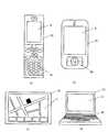
また、本発明による近接検出装置及び近接検出方法により、図7aに示すような携帯電話や図7bに示すようなマルチメデイアプレーヤーや図7cに示すようなナビゲ―ションシステムや図7dに示すようなコンピュータなどのディスプレイ装置上に透明な検出パネルを重ねることにより、ノイズに強い安定したスムーズな操作を可能にした携帯機器やコンピュータなどの情報機器を構成することが出来る。 In addition, the proximity detection apparatus and proximity detection method according to the present invention enables a mobile phone as shown in FIG. 7a, a multimedia player as shown in FIG. 7b, a navigation system as shown in FIG. 7c, or as shown in FIG. 7d. By superimposing a transparent detection panel on a display device such as a computer, it is possible to configure an information device such as a portable device or a computer that enables stable and smooth operation resistant to noise.
図7(a)〜(d)に示す情報機器の構成として、情報機器を保護するケース19と、情報を出力するディスプレイと、ディスプレイ上に設置された検出領域2からの入力を受け付け物体の接近や位置を特定する本発明の近接検出装置と、近接検出装置からの入力と、ディスプレイへの出力を制御するCPUと、により成り立つ。また、図7(a)、図7(b)や図7(d)に示されるようにキーボード18が情報機器に備え付けられていても良い。 7 (a) to 7 (d), the
1 支持手段
2 検出領域
3 送信電極
4 受信電極
5 マルチライン駆動手段
6 電流測定手段
7 線形演算手段
8 近接演算手段
9a 制御手段
9b 制御手段
10a 演算手段
10b 演算手段
11 矩形波発生手段
12 送信電圧行列参照手段
13 選択手段
14 遅延時間調整手段
15 記憶手段
16 インバータ
17 相関演算手段
18 キーボード
19 ケース
20 駆動測定工程
21 電流測定工程
22 線形演算工程
23 近接演算工程
24 マルチライン波形発生工程
25 遅延時間調整工程
26 マルチライン駆動工程
30 演算工程
35 線順次駆動手段
40 タイミング信号発生手段
41 インターバル発生手段
42 パワーセーブモード切替手段DESCRIPTION OF
Claims (15)
Translated fromJapanese支持手段上の検出領域における2つの次元のうち一方の次元に対応する複数の送信電極と、他方の1つの次元に対応する受信電極と、
前記送信電極の少なくとも二つ以上の電極に周期的な交流電圧を同時に印加するマルチライン駆動手段と、
前記受信電極からの電流あるいは蓄積された電荷量を前記送信電極への駆動に同期して測定する電流測定手段と、
前記電流測定手段で測定した電流値あるいは蓄積された電荷量を前記送信電極と前記受信電極の各交点の静電容量に対応した値に変換し前記検出領域への物体の接近判定或いは接近位置を求める演算手段と、
前記マルチライン駆動手段と前記電流測定手段と前記演算手段のステータス及びシーケンスを管理する制御手段とにより構成され、
前記演算手段は、
前記電流測定手段で測定した電流値あるいは蓄積された電荷量を線形演算し前記送信電極と前記受信電極の各交点の静電容量に対応した値に変換する線形演算手段と、
前記線形演算手段の出力から前記検出領域への物体の接近判定或いは接近位置を求める近接演算手段とにより構成され、
前記線形演算手段は、演算の途中結果を記憶し複数回読み出される記憶手段を有する近接検出装置。A proximity detection device for determining the approach or position of an object,
A plurality of transmitting electrodes corresponding to one of the two dimensions in the detection region on the support means; a receiving electrode corresponding to the other one dimension;
Multiline driving means for simultaneously applying a periodic alternating voltage to at least two of the transmitting electrodes;
Current measuring means for measuring the current from the receiving electrode or the accumulated charge amount in synchronization with the driving of the transmitting electrode;
The current value measured by the current measuring means or the accumulated charge amount is converted into a value corresponding to the capacitance at each intersection of the transmitting electrode and the receiving electrode, and the approach determination or approach position of the object to the detection region is determined. A computing means to obtain;
The multi-line drive means, the current measurement means, and a control means for managing the status and sequence of the calculation means,
The computing means is
Linear calculation means for linearly calculating a current value measured by the current measurement means or an accumulated charge amount and converting the value into a value corresponding to a capacitance at each intersection of the transmission electrode and the reception electrode;
It is constituted by proximity calculation means for obtaining an approach determination or an approach position of an object to the detection region from the output of the linear calculation means,
The linear calculation unit is a proximity detection device having a storage unit that stores a result of calculation in progress and is read out a plurality of times.
物体の接近を検出する検出領域における2つの次元のうち一方の次元に対応する複数の送信電極に同時に周期的な交流電圧を印加するマルチライン駆動工程と、
他方の次元に対応する受信電極からの電流あるいは蓄積された電荷量を前記送信電極への駆動に同期して測定する電流駆動測定工程と、
高速アダマール変換により線形演算し前記送信電極と前記受信電極の各交点の静電容量に対応した値に変換し、前記検出領域への物体の検出判定或いは近接位置を求める演算工程と、
により成り立つ近接検出方法。A proximity detection method for determining an approach of an object or obtaining an approach position,
A multiline driving step of simultaneously applying periodic alternating voltages to a plurality of transmission electrodes corresponding to one of the two dimensions in a detection region for detecting the approach of an object;
A current drive measurement step of measuring the current from the receiving electrode corresponding to the other dimension or the accumulated charge amount in synchronization with the driving to the transmitting electrode;
A linear operation by high-speed Hadamard transform and converted into a value corresponding to the capacitance of each intersection of the transmission electrode and the reception electrode, a calculation step for obtaining detection detection or proximity position of the object to the detection region;
Proximity detection method established by
Priority Applications (2)
| Application Number | Priority Date | Filing Date | Title |
|---|---|---|---|
| JP2009195970AJP2011047774A (en) | 2009-08-26 | 2009-08-26 | Proximity detection device and proximity detection method |
| US12/806,653US8682949B2 (en) | 2009-08-26 | 2010-08-18 | Proximity detection device and proximity detection method |
Applications Claiming Priority (1)
| Application Number | Priority Date | Filing Date | Title |
|---|---|---|---|
| JP2009195970AJP2011047774A (en) | 2009-08-26 | 2009-08-26 | Proximity detection device and proximity detection method |
Publications (1)
| Publication Number | Publication Date |
|---|---|
| JP2011047774Atrue JP2011047774A (en) | 2011-03-10 |
Family
ID=43626438
Family Applications (1)
| Application Number | Title | Priority Date | Filing Date |
|---|---|---|---|
| JP2009195970APendingJP2011047774A (en) | 2009-08-26 | 2009-08-26 | Proximity detection device and proximity detection method |
Country Status (2)
| Country | Link |
|---|---|
| US (1) | US8682949B2 (en) |
| JP (1) | JP2011047774A (en) |
Cited By (18)
| Publication number | Priority date | Publication date | Assignee | Title |
|---|---|---|---|---|
| WO2012160839A1 (en)* | 2011-05-25 | 2012-11-29 | シャープ株式会社 | Linear system coefficient estimating method, integrated circuit, and electronic device |
| WO2012169215A1 (en)* | 2011-06-10 | 2012-12-13 | シャープ株式会社 | Touch panel controller and electronic apparatus employing same |
| WO2013001996A1 (en)* | 2011-06-29 | 2013-01-03 | Sharp Kabushiki Kaisha | Linear device value estimating method, capacitance detecting method, integrated circuit, touch sensor system, and electronic device |
| JP2013025584A (en)* | 2011-07-21 | 2013-02-04 | Sharp Corp | Information processor |
| JP2013065212A (en)* | 2011-09-16 | 2013-04-11 | Sharp Corp | Touch panel controller, touch panel unit, touch panel driving method, and electronic information device |
| WO2013061550A1 (en)* | 2011-10-25 | 2013-05-02 | Sharp Kabushiki Kaisha | Touch panel system and electronic device |
| WO2013151060A1 (en)* | 2012-04-04 | 2013-10-10 | シャープ株式会社 | Touch panel controller, integrated circuit, touch panel system, and electronic device |
| WO2014002907A1 (en)* | 2012-06-25 | 2014-01-03 | シャープ株式会社 | Touch panel controller, integrated circuit, touch panel device, and electronic device |
| WO2014038519A1 (en)* | 2012-09-05 | 2014-03-13 | シャープ株式会社 | Touch panel controller, integrated circuit including same, touch panel device, and electronic device |
| JP2014519066A (en)* | 2011-07-12 | 2014-08-07 | シャープ株式会社 | Touch panel system and electronic device |
| JP2014519065A (en)* | 2011-07-12 | 2014-08-07 | シャープ株式会社 | Touch panel system and electronic device |
| JP2014520292A (en)* | 2011-06-29 | 2014-08-21 | シャープ株式会社 | Linear element value estimation method, capacitance detection method, integrated circuit, touch sensor system, and electronic device |
| JP2014186535A (en)* | 2013-03-22 | 2014-10-02 | Japan Display Inc | Touch sensor device, display device, and electronic apparatus |
| WO2015137416A1 (en)* | 2014-03-12 | 2015-09-17 | シャープ株式会社 | Signal processing system, touch panel system, and electronic device |
| US9146632B2 (en) | 2011-06-29 | 2015-09-29 | Sharp Kabushiki Kaisha | Linear device value estimating method, capacitance detecting method, integrated circuit, touch sensor system, and electronic device |
| JP2016081486A (en)* | 2014-10-22 | 2016-05-16 | アルプス電気株式会社 | Capacitance type detection device |
| WO2018193711A1 (en)* | 2017-04-20 | 2018-10-25 | アルプス電気株式会社 | Touch sensor-type electronic device and sensor control method |
| CN112534108A (en)* | 2018-08-15 | 2021-03-19 | 阿尔卑斯阿尔派株式会社 | Door handle |
Families Citing this family (30)
| Publication number | Priority date | Publication date | Assignee | Title |
|---|---|---|---|---|
| JPWO2009107415A1 (en)* | 2008-02-27 | 2011-06-30 | セイコーインスツル株式会社 | Proximity detection device and proximity detection method |
| US8866500B2 (en) | 2009-03-26 | 2014-10-21 | Cypress Semiconductor Corporation | Multi-functional capacitance sensing circuit with a current conveyor |
| JP2011257884A (en)* | 2010-06-07 | 2011-12-22 | Seiko Instruments Inc | Electrostatic coordinate input device, electrostatic coordinate input method and information appliance |
| CN102576275B (en) | 2010-08-23 | 2016-08-31 | 谱瑞科技股份有限公司 | mutual capacitance sensing circuit, method and system |
| US9013441B2 (en) | 2010-08-24 | 2015-04-21 | Cypress Semiconductor Corporation | Smart scanning for a capacitive sensing array |
| US9285902B1 (en) | 2010-08-25 | 2016-03-15 | Parade Technologies, Ltd. | Multi-phase scanning |
| JP4927216B1 (en) | 2010-11-12 | 2012-05-09 | シャープ株式会社 | Linear element array value estimation method, capacitance detection method, integrated circuit, touch sensor system, and electronic device |
| US8729911B2 (en) | 2011-04-19 | 2014-05-20 | Cypress Semiconductor Corporation | Usage of weighting matrices in multi-phase scanning modes |
| US11320946B2 (en)* | 2011-04-19 | 2022-05-03 | Cypress Semiconductor Corporation | Capacitive panel scanning with reduced number of sensing circuits |
| JP5539269B2 (en)* | 2011-06-27 | 2014-07-02 | シャープ株式会社 | Capacitance value distribution detection method, capacitance value distribution detection circuit, touch sensor system, and information input / output device |
| JP5350437B2 (en) | 2011-06-27 | 2013-11-27 | シャープ株式会社 | Touch sensor system |
| WO2013001920A1 (en) | 2011-06-29 | 2013-01-03 | Sharp Kabushiki Kaisha | Touch sensor system and electronic device |
| TWI514231B (en)* | 2012-05-18 | 2015-12-21 | Egalax Empia Technology Inc | Detecting method and device for capacitive touch screen |
| US9235280B1 (en)* | 2012-05-24 | 2016-01-12 | Qualcomm Technologies, Inc. | Mutual capacitance large panel phase shift mitigation |
| US8860682B1 (en) | 2013-04-22 | 2014-10-14 | Cypress Semiconductor Corporation | Hardware de-convolution block for multi-phase scanning |
| CA2917045A1 (en) | 2013-08-19 | 2015-02-26 | Touchsensor Technologies, Llc | Capacitive sensor filtering method |
| US9569054B2 (en)* | 2013-08-19 | 2017-02-14 | Touchsensor Technologies, Llc | Capacitive sensor filtering apparatus, method, and system |
| US10013113B2 (en) | 2013-08-19 | 2018-07-03 | Touchsensor Technologies, Llc | Capacitive sensor filtering apparatus, method, and system |
| KR101531162B1 (en) | 2013-09-16 | 2015-06-25 | 주식회사 하이딥 | Touch panel input apparatus and input detection method thereof |
| US9253733B1 (en)* | 2014-03-19 | 2016-02-02 | Amazon Technologies, Inc. | Proximity sensor algorithms to control transmit power of a user device |
| US10108292B2 (en)* | 2015-04-22 | 2018-10-23 | Microchip Technology Incorporated | Capacitive sensor system with multiple transmit electrodes |
| JP6430331B2 (en) | 2015-05-18 | 2018-11-28 | アルプス電気株式会社 | Input device, input device control method, and program for causing computer to execute input device control method |
| US10004048B2 (en)* | 2016-04-01 | 2018-06-19 | Intel Corporation | Transmission power control methods and devices |
| US10768746B1 (en) | 2016-05-10 | 2020-09-08 | Apple Inc. | Quasi-continuous-time sampling of discrete-time sampled signals |
| US10691258B2 (en) | 2018-01-12 | 2020-06-23 | Idex Biometrics Asa | Systems and methods for noise reduction in sensors |
| US11106310B2 (en) | 2019-08-22 | 2021-08-31 | Idex Biometrics Asa | Systems and methods for improving image quality in sensors |
| US10915724B2 (en) | 2018-08-22 | 2021-02-09 | Idex Biometrics Asa | Systems and methods for improving image quality in sensors |
| JP7245638B2 (en) | 2018-11-30 | 2023-03-24 | 株式会社ジャパンディスプレイ | detector |
| US11042773B2 (en) | 2019-01-11 | 2021-06-22 | Idex Biometrics Asa | Systems and methods for accelerating data capture in sensors |
| CN113824400B (en)* | 2021-08-25 | 2023-08-22 | 西安电子科技大学 | Measuring Method of Photovoltaic Cell Energy Efficiency Map Based on Quadrature Modulation |
Family Cites Families (8)
| Publication number | Priority date | Publication date | Assignee | Title |
|---|---|---|---|---|
| JP3281256B2 (en) | 1996-04-24 | 2002-05-13 | シャープ株式会社 | Coordinate input device |
| JP3394187B2 (en)* | 1997-08-08 | 2003-04-07 | シャープ株式会社 | Coordinate input device and display integrated type coordinate input device |
| JP2000148376A (en) | 1998-11-09 | 2000-05-26 | Toshiba Corp | Data input device |
| US6452514B1 (en)* | 1999-01-26 | 2002-09-17 | Harald Philipp | Capacitive sensor and array |
| JP2000259348A (en) | 1999-03-11 | 2000-09-22 | Sharp Corp | Coordinate input device |
| US7868874B2 (en)* | 2005-11-15 | 2011-01-11 | Synaptics Incorporated | Methods and systems for detecting a position-based attribute of an object using digital codes |
| US7812827B2 (en)* | 2007-01-03 | 2010-10-12 | Apple Inc. | Simultaneous sensing arrangement |
| GB2448821A (en)* | 2007-04-24 | 2008-10-29 | Seiko Instr Inc | Differential capacitive proximity detector |
- 2009
- 2009-08-26JPJP2009195970Apatent/JP2011047774A/enactivePending
- 2010
- 2010-08-18USUS12/806,653patent/US8682949B2/enactiveActive
Cited By (31)
| Publication number | Priority date | Publication date | Assignee | Title |
|---|---|---|---|---|
| WO2012160839A1 (en)* | 2011-05-25 | 2012-11-29 | シャープ株式会社 | Linear system coefficient estimating method, integrated circuit, and electronic device |
| JP2012247870A (en)* | 2011-05-25 | 2012-12-13 | Sharp Corp | Capacitance estimation method, integrated circuit, and electronic apparatus |
| US9395856B2 (en) | 2011-05-25 | 2016-07-19 | Sharp Kabushiki Kaishi | Linear system coefficient estimating method, integrated circuit, and electronic device |
| WO2012169215A1 (en)* | 2011-06-10 | 2012-12-13 | シャープ株式会社 | Touch panel controller and electronic apparatus employing same |
| US8730197B2 (en) | 2011-06-10 | 2014-05-20 | Sharp Kabushiki Kaisha | Touch panel controller and electronic apparatus employing same |
| JP2013003603A (en)* | 2011-06-10 | 2013-01-07 | Sharp Corp | Touch panel controller and electronic apparatus using the same |
| US9146632B2 (en) | 2011-06-29 | 2015-09-29 | Sharp Kabushiki Kaisha | Linear device value estimating method, capacitance detecting method, integrated circuit, touch sensor system, and electronic device |
| WO2013001996A1 (en)* | 2011-06-29 | 2013-01-03 | Sharp Kabushiki Kaisha | Linear device value estimating method, capacitance detecting method, integrated circuit, touch sensor system, and electronic device |
| JP2014520292A (en)* | 2011-06-29 | 2014-08-21 | シャープ株式会社 | Linear element value estimation method, capacitance detection method, integrated circuit, touch sensor system, and electronic device |
| JP2014519065A (en)* | 2011-07-12 | 2014-08-07 | シャープ株式会社 | Touch panel system and electronic device |
| JP2014519066A (en)* | 2011-07-12 | 2014-08-07 | シャープ株式会社 | Touch panel system and electronic device |
| JP2013025584A (en)* | 2011-07-21 | 2013-02-04 | Sharp Corp | Information processor |
| JP2013065212A (en)* | 2011-09-16 | 2013-04-11 | Sharp Corp | Touch panel controller, touch panel unit, touch panel driving method, and electronic information device |
| WO2013061550A1 (en)* | 2011-10-25 | 2013-05-02 | Sharp Kabushiki Kaisha | Touch panel system and electronic device |
| JP2013092872A (en)* | 2011-10-25 | 2013-05-16 | Sharp Corp | Touch panel system and electronic apparatus |
| US8994692B2 (en) | 2011-10-25 | 2015-03-31 | Sharp Kabushiki Kaisha | Touch panel system and electronic device |
| JP2013218386A (en)* | 2012-04-04 | 2013-10-24 | Sharp Corp | Touch panel controller, integrated circuit, touch panel system and electronic equipment |
| WO2013151060A1 (en)* | 2012-04-04 | 2013-10-10 | シャープ株式会社 | Touch panel controller, integrated circuit, touch panel system, and electronic device |
| WO2014002907A1 (en)* | 2012-06-25 | 2014-01-03 | シャープ株式会社 | Touch panel controller, integrated circuit, touch panel device, and electronic device |
| WO2014038519A1 (en)* | 2012-09-05 | 2014-03-13 | シャープ株式会社 | Touch panel controller, integrated circuit including same, touch panel device, and electronic device |
| JP2014186535A (en)* | 2013-03-22 | 2014-10-02 | Japan Display Inc | Touch sensor device, display device, and electronic apparatus |
| WO2015137416A1 (en)* | 2014-03-12 | 2015-09-17 | シャープ株式会社 | Signal processing system, touch panel system, and electronic device |
| JP5989937B2 (en)* | 2014-03-12 | 2016-09-07 | シャープ株式会社 | Signal processing system, touch panel system, and electronic device |
| JP2016081486A (en)* | 2014-10-22 | 2016-05-16 | アルプス電気株式会社 | Capacitance type detection device |
| WO2018193711A1 (en)* | 2017-04-20 | 2018-10-25 | アルプス電気株式会社 | Touch sensor-type electronic device and sensor control method |
| CN110520831A (en)* | 2017-04-20 | 2019-11-29 | 阿尔卑斯阿尔派株式会社 | Touch sensor formula electronic device and sensor control method |
| JPWO2018193711A1 (en)* | 2017-04-20 | 2020-05-14 | アルプスアルパイン株式会社 | Touch sensor type electronic device and sensor control method |
| US11216135B2 (en) | 2017-04-20 | 2022-01-04 | Alps Alpine Co., Ltd. | Touch-sensitive electronic device and sensor control method |
| CN110520831B (en)* | 2017-04-20 | 2023-06-20 | 阿尔卑斯阿尔派株式会社 | Touch sensor electronic device and sensor control method |
| CN112534108A (en)* | 2018-08-15 | 2021-03-19 | 阿尔卑斯阿尔派株式会社 | Door handle |
| CN112534108B (en)* | 2018-08-15 | 2022-03-25 | 阿尔卑斯阿尔派株式会社 | Door handle |
Also Published As
| Publication number | Publication date |
|---|---|
| US20110055305A1 (en) | 2011-03-03 |
| US8682949B2 (en) | 2014-03-25 |
Similar Documents
| Publication | Publication Date | Title |
|---|---|---|
| JP2011047774A (en) | Proximity detection device and proximity detection method | |
| WO2009107415A1 (en) | Proximity detector and proximity detection method | |
| JP2011003071A (en) | Proximity detection device and proximity detection method | |
| JP6436374B2 (en) | Electronic equipment, capacitance sensor and touch panel | |
| TWI448946B (en) | Position detecting device and position detecting method | |
| US11320946B2 (en) | Capacitive panel scanning with reduced number of sensing circuits | |
| CA2805104C (en) | Capacitive touch sensor having correlation with a receiver | |
| US8928622B2 (en) | Demodulation method and system with low common noise and high SNR for a low-power differential sensing capacitive touch panel | |
| CN107168579B (en) | Techniques for locally improving signal-to-noise ratio in capacitive touch sensors | |
| KR101863160B1 (en) | Capacitive touch sensor having code-divided and time-divided transmit waveforms | |
| TWI701586B (en) | Capacitive touch system using differential sensing and operating method thereof | |
| US20110304585A1 (en) | Method and device for signal detection | |
| JP2011076265A (en) | Coordinate input device | |
| TW201423514A (en) | Signal processing system, touch panel controller, and touch panel system and electronic apparatus using touch panel controller | |
| US20150234521A1 (en) | Clustered scan method of a capacitive touch device | |
| US20150138152A1 (en) | Control unit, sensing device for a capacitive touch panel and method thereof | |
| TW201140412A (en) | Position detecting device and method | |
| US20250094011A1 (en) | Sensor apparatus, integrated circuit, and method of detecting indicator | |
| JP2018160174A (en) | Touch detection apparatus | |
| TW201519060A (en) | Method for recognizing touch signal and device thereof | |
| CN103970382A (en) | Capacitive touch sensing device and detection method thereof | |
| JP6928723B2 (en) | Capacitance sensor and its control method and program | |
| CN114139581B (en) | Signal measurement method, signal measurement circuit, touch sensor and electronic device | |
| JP6612983B2 (en) | Position detection device |