JP2011045544A - Indwelling needle assembly - Google Patents
Indwelling needle assemblyDownload PDFInfo
- Publication number
- JP2011045544A JP2011045544AJP2009196830AJP2009196830AJP2011045544AJP 2011045544 AJP2011045544 AJP 2011045544AJP 2009196830 AJP2009196830 AJP 2009196830AJP 2009196830 AJP2009196830 AJP 2009196830AJP 2011045544 AJP2011045544 AJP 2011045544A
- Authority
- JP
- Japan
- Prior art keywords
- needle
- inner needle
- base end
- indwelling
- needle hub
- Prior art date
- Legal status (The legal status is an assumption and is not a legal conclusion. Google has not performed a legal analysis and makes no representation as to the accuracy of the status listed.)
- Pending
Links
- 239000000463materialSubstances0.000claimsabstractdescription39
- 210000003811fingerAnatomy0.000claimsdescription45
- 210000003813thumbAnatomy0.000claimsdescription17
- 229920005989resinPolymers0.000claimsdescription9
- 239000011347resinSubstances0.000claimsdescription9
- 230000001012protectorEffects0.000description72
- 238000001802infusionMethods0.000description23
- 210000004204blood vesselAnatomy0.000description22
- 238000000034methodMethods0.000description21
- 239000000470constituentSubstances0.000description19
- 230000002093peripheral effectEffects0.000description7
- 210000004369bloodAnatomy0.000description6
- 239000008280bloodSubstances0.000description6
- -1polyethylenePolymers0.000description6
- 239000004743PolypropyleneSubstances0.000description5
- 238000003780insertionMethods0.000description5
- 230000037431insertionEffects0.000description5
- 229920001200poly(ethylene-vinyl acetate)Polymers0.000description5
- 230000008569processEffects0.000description5
- 239000000853adhesiveSubstances0.000description4
- 230000001070adhesive effectEffects0.000description4
- 239000005038ethylene vinyl acetateSubstances0.000description4
- 229920002647polyamidePolymers0.000description4
- 229920000728polyesterPolymers0.000description4
- 229920001155polypropylenePolymers0.000description4
- 229920002635polyurethanePolymers0.000description4
- 239000004814polyurethaneSubstances0.000description4
- 239000007787solidSubstances0.000description4
- 239000004952PolyamideSubstances0.000description3
- 239000005062PolybutadieneSubstances0.000description3
- 239000004698PolyethyleneSubstances0.000description3
- 230000017531blood circulationEffects0.000description3
- 229920003049isoprene rubberPolymers0.000description3
- 239000007788liquidSubstances0.000description3
- 239000000314lubricantSubstances0.000description3
- 239000000203mixtureSubstances0.000description3
- 229920002857polybutadienePolymers0.000description3
- 229920000515polycarbonatePolymers0.000description3
- 239000004417polycarbonateSubstances0.000description3
- 239000004800polyvinyl chlorideSubstances0.000description3
- 238000007789sealingMethods0.000description3
- 229920002379silicone rubberPolymers0.000description3
- 239000004945silicone rubberSubstances0.000description3
- 229910000838Al alloyInorganic materials0.000description2
- YCKRFDGAMUMZLT-UHFFFAOYSA-NFluorine atomChemical compound[F]YCKRFDGAMUMZLT-UHFFFAOYSA-N0.000description2
- PPBRXRYQALVLMV-UHFFFAOYSA-NStyreneChemical compoundC=CC1=CC=CC=C1PPBRXRYQALVLMV-UHFFFAOYSA-N0.000description2
- 229910001069Ti alloyInorganic materials0.000description2
- RTAQQCXQSZGOHL-UHFFFAOYSA-NTitaniumChemical compound[Ti]RTAQQCXQSZGOHL-UHFFFAOYSA-N0.000description2
- 239000002390adhesive tapeSubstances0.000description2
- 229910052782aluminiumInorganic materials0.000description2
- XAGFODPZIPBFFR-UHFFFAOYSA-NaluminiumChemical compound[Al]XAGFODPZIPBFFR-UHFFFAOYSA-N0.000description2
- TZCXTZWJZNENPQ-UHFFFAOYSA-Lbarium sulfateChemical compound[Ba+2].[O-]S([O-])(=O)=OTZCXTZWJZNENPQ-UHFFFAOYSA-L0.000description2
- 229920001971elastomerPolymers0.000description2
- 239000011737fluorineSubstances0.000description2
- 229910052731fluorineInorganic materials0.000description2
- 230000036512infertilityEffects0.000description2
- 239000003978infusion fluidSubstances0.000description2
- 239000007769metal materialSubstances0.000description2
- 229920000573polyethylenePolymers0.000description2
- 229920000098polyolefinPolymers0.000description2
- 229920005672polyolefin resinPolymers0.000description2
- 229920000915polyvinyl chloridePolymers0.000description2
- 239000005060rubberSubstances0.000description2
- 239000000243solutionSubstances0.000description2
- 239000010935stainless steelSubstances0.000description2
- 229910001220stainless steelInorganic materials0.000description2
- 239000000126substanceSubstances0.000description2
- 239000010936titaniumSubstances0.000description2
- 229910052719titaniumInorganic materials0.000description2
- RYGMFSIKBFXOCR-UHFFFAOYSA-NCopperChemical compound[Cu]RYGMFSIKBFXOCR-UHFFFAOYSA-N0.000description1
- 229910000881Cu alloyInorganic materials0.000description1
- JOYRKODLDBILNP-UHFFFAOYSA-NEthyl urethaneChemical compoundCCOC(N)=OJOYRKODLDBILNP-UHFFFAOYSA-N0.000description1
- 244000043261Hevea brasiliensisSpecies0.000description1
- 229920000459Nitrile rubberPolymers0.000description1
- 239000004677NylonSubstances0.000description1
- 229930182556PolyacetalNatural products0.000description1
- 239000004721Polyphenylene oxideSubstances0.000description1
- VYPSYNLAJGMNEJ-UHFFFAOYSA-NSilicium dioxideChemical compoundO=[Si]=OVYPSYNLAJGMNEJ-UHFFFAOYSA-N0.000description1
- 229920006311Urethane elastomerPolymers0.000description1
- 210000001015abdomenAnatomy0.000description1
- 229920000800acrylic rubberPolymers0.000description1
- 230000009471actionEffects0.000description1
- 150000001336alkenesChemical class0.000description1
- 210000001367arteryAnatomy0.000description1
- 230000000712assemblyEffects0.000description1
- 238000000429assemblyMethods0.000description1
- AYJRCSIUFZENHW-DEQYMQKBSA-Lbarium(2+);oxomethanediolateChemical compound[Ba+2].[O-][14C]([O-])=OAYJRCSIUFZENHW-DEQYMQKBSA-L0.000description1
- 238000005452bendingMethods0.000description1
- 230000008901benefitEffects0.000description1
- 229940036348bismuth carbonateDrugs0.000description1
- 238000005422blastingMethods0.000description1
- 230000036772blood pressureEffects0.000description1
- 229920005549butyl rubberPolymers0.000description1
- 239000003795chemical substances by applicationSubstances0.000description1
- 239000012141concentrateSubstances0.000description1
- 239000002872contrast mediaSubstances0.000description1
- 239000010949copperSubstances0.000description1
- 229910052802copperInorganic materials0.000description1
- 238000010586diagramMethods0.000description1
- GMZOPRQQINFLPQ-UHFFFAOYSA-Hdibismuth;tricarbonateChemical compound[Bi+3].[Bi+3].[O-]C([O-])=O.[O-]C([O-])=O.[O-]C([O-])=OGMZOPRQQINFLPQ-UHFFFAOYSA-H0.000description1
- 239000013013elastic materialSubstances0.000description1
- 238000004049embossingMethods0.000description1
- 229920000840ethylene tetrafluoroethylene copolymerPolymers0.000description1
- 239000002783friction materialSubstances0.000description1
- 230000012447hatchingEffects0.000description1
- 239000008155medical solutionSubstances0.000description1
- 238000000465mouldingMethods0.000description1
- 229920003052natural elastomerPolymers0.000description1
- 229920001194natural rubberPolymers0.000description1
- 229920006173natural rubber latexPolymers0.000description1
- 150000002825nitrilesChemical class0.000description1
- 229920001778nylonPolymers0.000description1
- JRZJOMJEPLMPRA-UHFFFAOYSA-NolefinNatural productsCCCCCCCC=CJRZJOMJEPLMPRA-UHFFFAOYSA-N0.000description1
- 230000000149penetrating effectEffects0.000description1
- 229920011301perfluoro alkoxyl alkanePolymers0.000description1
- 229920000058polyacrylatePolymers0.000description1
- 229920000570polyetherPolymers0.000description1
- 229920006324polyoxymethylenePolymers0.000description1
- 229920005606polypropylene copolymerPolymers0.000description1
- 229920001343polytetrafluoroethylenePolymers0.000description1
- 239000004810polytetrafluoroethyleneSubstances0.000description1
- 238000003825pressingMethods0.000description1
- 230000037452primingEffects0.000description1
- 238000011946reduction processMethods0.000description1
- 229920002545silicone oilPolymers0.000description1
- 239000002904solventSubstances0.000description1
- 238000003860storageMethods0.000description1
- 229920003048styrene butadiene rubberPolymers0.000description1
- 239000004094surface-active agentSubstances0.000description1
- 229920002725thermoplastic elastomerPolymers0.000description1
- CMPGARWFYBADJI-UHFFFAOYSA-Ltungstic acidChemical compoundO[W](O)(=O)=OCMPGARWFYBADJI-UHFFFAOYSA-L0.000description1
- 210000003462veinAnatomy0.000description1
- 238000004073vulcanizationMethods0.000description1
Images


Classifications
- A—HUMAN NECESSITIES
- A61—MEDICAL OR VETERINARY SCIENCE; HYGIENE
- A61M—DEVICES FOR INTRODUCING MEDIA INTO, OR ONTO, THE BODY; DEVICES FOR TRANSDUCING BODY MEDIA OR FOR TAKING MEDIA FROM THE BODY; DEVICES FOR PRODUCING OR ENDING SLEEP OR STUPOR
- A61M5/00—Devices for bringing media into the body in a subcutaneous, intra-vascular or intramuscular way; Accessories therefor, e.g. filling or cleaning devices, arm-rests
- A61M5/14—Infusion devices, e.g. infusing by gravity; Blood infusion; Accessories therefor
- A61M5/158—Needles for infusions; Accessories therefor, e.g. for inserting infusion needles, or for holding them on the body
- A61M2005/1586—Holding accessories for holding infusion needles on the body
- A—HUMAN NECESSITIES
- A61—MEDICAL OR VETERINARY SCIENCE; HYGIENE
- A61M—DEVICES FOR INTRODUCING MEDIA INTO, OR ONTO, THE BODY; DEVICES FOR TRANSDUCING BODY MEDIA OR FOR TAKING MEDIA FROM THE BODY; DEVICES FOR PRODUCING OR ENDING SLEEP OR STUPOR
- A61M5/00—Devices for bringing media into the body in a subcutaneous, intra-vascular or intramuscular way; Accessories therefor, e.g. filling or cleaning devices, arm-rests
- A61M5/178—Syringes
- A61M5/31—Details
- A61M5/32—Needles; Details of needles pertaining to their connection with syringe or hub; Accessories for bringing the needle into, or holding the needle on, the body; Devices for protection of needles
- A61M5/3205—Apparatus for removing or disposing of used needles or syringes, e.g. containers; Means for protection against accidental injuries from used needles
- A61M5/321—Means for protection against accidental injuries by used needles
- A61M5/3243—Means for protection against accidental injuries by used needles being axially-extensible, e.g. protective sleeves coaxially slidable on the syringe barrel
- A61M5/3245—Constructional features thereof, e.g. to improve manipulation or functioning
- A61M2005/3247—Means to impede repositioning of protection sleeve from needle covering to needle uncovering position
- A61M2005/325—Means obstructing the needle passage at distal end of a needle protection sleeve
- A—HUMAN NECESSITIES
- A61—MEDICAL OR VETERINARY SCIENCE; HYGIENE
- A61M—DEVICES FOR INTRODUCING MEDIA INTO, OR ONTO, THE BODY; DEVICES FOR TRANSDUCING BODY MEDIA OR FOR TAKING MEDIA FROM THE BODY; DEVICES FOR PRODUCING OR ENDING SLEEP OR STUPOR
- A61M25/00—Catheters; Hollow probes
- A61M25/01—Introducing, guiding, advancing, emplacing or holding catheters
- A61M25/06—Body-piercing guide needles or the like
- A61M25/0612—Devices for protecting the needle; Devices to help insertion of the needle, e.g. wings or holders
- A61M25/0618—Devices for protecting the needle; Devices to help insertion of the needle, e.g. wings or holders having means for protecting only the distal tip of the needle, e.g. a needle guard
- A61M25/0625—Devices for protecting the needle; Devices to help insertion of the needle, e.g. wings or holders having means for protecting only the distal tip of the needle, e.g. a needle guard with a permanent connection to the needle hub, e.g. a guiding rail, a locking mechanism or a guard advancement mechanism
- A—HUMAN NECESSITIES
- A61—MEDICAL OR VETERINARY SCIENCE; HYGIENE
- A61M—DEVICES FOR INTRODUCING MEDIA INTO, OR ONTO, THE BODY; DEVICES FOR TRANSDUCING BODY MEDIA OR FOR TAKING MEDIA FROM THE BODY; DEVICES FOR PRODUCING OR ENDING SLEEP OR STUPOR
- A61M5/00—Devices for bringing media into the body in a subcutaneous, intra-vascular or intramuscular way; Accessories therefor, e.g. filling or cleaning devices, arm-rests
- A61M5/178—Syringes
- A61M5/31—Details
- A61M5/32—Needles; Details of needles pertaining to their connection with syringe or hub; Accessories for bringing the needle into, or holding the needle on, the body; Devices for protection of needles
- A61M5/3205—Apparatus for removing or disposing of used needles or syringes, e.g. containers; Means for protection against accidental injuries from used needles
- A61M5/321—Means for protection against accidental injuries by used needles
- A61M5/3243—Means for protection against accidental injuries by used needles being axially-extensible, e.g. protective sleeves coaxially slidable on the syringe barrel
- A61M5/3275—Means for protection against accidental injuries by used needles being axially-extensible, e.g. protective sleeves coaxially slidable on the syringe barrel being connected to the needle hub or syringe by radially deflectable members, e.g. longitudinal slats, cords or bands
Landscapes
- Health & Medical Sciences (AREA)
- Vascular Medicine (AREA)
- Engineering & Computer Science (AREA)
- Anesthesiology (AREA)
- Biomedical Technology (AREA)
- Heart & Thoracic Surgery (AREA)
- Hematology (AREA)
- Life Sciences & Earth Sciences (AREA)
- Animal Behavior & Ethology (AREA)
- General Health & Medical Sciences (AREA)
- Public Health (AREA)
- Veterinary Medicine (AREA)
- Infusion, Injection, And Reservoir Apparatuses (AREA)
- Media Introduction/Drainage Providing Device (AREA)
Abstract
Description
Translated fromJapanese本発明は、例えば輸液の際に血管に穿刺し、留置する留置針組立体に関する。 The present invention relates to an indwelling needle assembly that punctures a blood vessel, for example, during infusion.
患者に対し輸液を行う際などには、輸液ラインと接続される留置針を患者の血管に穿刺し、留置してこれを行う。 When an infusion is performed on a patient, an indwelling needle connected to the infusion line is punctured into the patient's blood vessel, and the indwelling needle is placed in place.
このような留置針組立体は、中空の外針と、外針の基端に固着された外針ハブと、外針内に挿入され、先端に鋭利な針先を有する内針と、内針の基端に固着された内針ハブと、外針ハブに対して着脱自在に連結されるプロテクタとで構成されている。外針ハブには、外針の内腔に連通する流路を有する主管と、この流路から分岐した分岐流路を有する側管とが形成されており、側管に、輸液ラインが接続されるようになっている(例えば、特許文献1参照)。 Such an indwelling needle assembly includes a hollow outer needle, an outer needle hub fixed to the proximal end of the outer needle, an inner needle inserted into the outer needle and having a sharp needle tip, and an inner needle. An inner needle hub fixed to the proximal end of the outer needle hub and a protector detachably connected to the outer needle hub. The outer needle hub is formed with a main pipe having a flow path communicating with the lumen of the outer needle and a side pipe having a branch flow path branched from the flow path, and an infusion line is connected to the side pipe. (For example, refer to Patent Document 1).
この留置針を患者の血管に穿刺する際には、内針を外針内に挿入し、内針の針先を外針の先端から突出させた組立状態で穿刺操作を行う。 When this indwelling needle is punctured into a patient's blood vessel, the puncture operation is performed in an assembled state in which the inner needle is inserted into the outer needle and the tip of the inner needle protrudes from the tip of the outer needle.
内針の針先が血管内に到達すると、内針の先端部から血液が流入し、その血液は、途中で、内針の側部に形成された孔部から外針と内針の間の流路へ流入し、その流路を通り、透明な外針ハブの内部、すなわち、主管の流路に流入し、さらに、主管から側管の分岐流路に流入する(フラッシュバック)。これにより、内針が血管を確保したことが確認(視認)できる。 When the needle tip of the inner needle reaches the inside of the blood vessel, blood flows from the tip of the inner needle, and the blood passes between the outer needle and the inner needle through a hole formed in the side portion of the inner needle. It flows into the flow path, passes through the flow path, flows into the transparent outer needle hub, that is, into the flow path of the main pipe, and then flows into the branch flow path of the side pipe (flashback). Thereby, it can confirm (visually recognize) that the inner needle secured the blood vessel.
このフラッシュバックを確認したら、内針をガイドとして、外針を進め、当該外針を血管内に穿刺する。 When this flashback is confirmed, the outer needle is advanced using the inner needle as a guide, and the outer needle is punctured into the blood vessel.
次いで、外針や外針ハブを一方の手で把持して固定しつつ、内針ハブを他方の手で把持して基端方向に移動させ、内針を外針から抜き取る。そして、接続された輸液ライン、外針ハブの側管、主管および外針を介して輸液剤を投与する。 Next, while holding and fixing the outer needle and the outer needle hub with one hand, the inner needle hub is held with the other hand and moved in the proximal direction, and the inner needle is removed from the outer needle. Then, the infusion agent is administered through the connected infusion line, the side tube of the outer needle hub, the main tube, and the outer needle.
ところで、医師(使用者)は、前記留置針組立体の外針を患者に留置する際、手袋を装着し、手指でその留置針組立体を把持して穿刺操作を行う。そして、この穿刺操作の際、医師は、例えば、図3に示す方法で留置針組立体を把持することがある。 By the way, when placing the outer needle of the indwelling needle assembly on the patient, the doctor (user) wears gloves and holds the indwelling needle assembly with fingers to perform the puncture operation. During this puncture operation, the doctor may grasp the indwelling needle assembly by the method shown in FIG. 3, for example.
この持ち方は、本明細書では、「ウイングポート持ち」と呼び、親指を内針ハブの基端に当接し、残りの指のうちの例えば中指を留置針組立体の先端側、すなわち、外針ハブの翼(ウイング)に当接し、これにより留置針組立体を長手方向から挟み付けて把持する。 In this specification, this holding method is referred to as “having a wing port”, the thumb is brought into contact with the proximal end of the inner needle hub, and the middle finger, for example, the middle finger is placed on the distal end side of the indwelling needle assembly, that is, the outer side. The abutment needle assembly is brought into contact with the wing (wing) of the needle hub, whereby the indwelling needle assembly is pinched and gripped from the longitudinal direction.
しかしながら、従来の留置針組立体では、穿刺操作の際、手袋を装着した手指が留置針組立体に対して滑り易く、特に、親指が内針ハブの基端から滑り易くなっており、これにより穿刺操作を行い難いという問題がある。 However, in the conventional indwelling needle assembly, a finger wearing a glove is slippery with respect to the indwelling needle assembly during the puncturing operation, and in particular, the thumb is slippery from the proximal end of the inner needle hub. There is a problem that it is difficult to perform a puncture operation.
本発明の目的は、滑り難く、穿刺操作を容易に行うことができる留置針組立体を提供することにある。 An object of the present invention is to provide an indwelling needle assembly that is difficult to slip and that can be easily punctured.
このような目的は、下記(1)〜(7)の本発明により達成される。
(1) 先端に鋭利な針先を有する内針と、
前記内針の基端部に固定された内針ハブと、
前記内針が挿通される中空の外針と、
前記外針の基端部に固定された外針ハブとを備え、前記内針ハブの基端部に親指を当接して使用する留置針組立体であって、
前記内針ハブの基端部に、医療用手袋に対して滑り難い材料で少なくとも一部を形成した指当部を設けたことを特徴とする留置針組立体。Such an object is achieved by the present inventions (1) to (7) below.
(1) an inner needle having a sharp needle tip at the tip;
An inner needle hub fixed to the proximal end of the inner needle;
A hollow outer needle through which the inner needle is inserted;
An indwelling needle assembly comprising an outer needle hub fixed to a proximal end portion of the outer needle, and used by contacting a thumb with the proximal end portion of the inner needle hub,
The indwelling needle assembly according to
(2) 前記内針ハブは、樹脂材料で形成された内針ハブ本体部を有しており、
前記指当部は、前記内針ハブ本体部の基端面より基端方向に突出し、前記滑り難い材料で形成された凸部を有する上記(1)に記載の留置針組立体。(2) The inner needle hub has an inner needle hub main body formed of a resin material,
The indwelling needle assembly according to (1), wherein the finger holding portion has a convex portion that protrudes in a proximal direction from a proximal end surface of the inner needle hub main body portion and is formed of the non-slip material.
(3) 前記凸部は、前記基端面の中心部に配置されている上記(2)に記載の留置針組立体。 (3) The indwelling needle assembly according to (2), wherein the convex portion is disposed at a central portion of the base end surface.
(4) 前記凸部の中心部に凹部が設けられている上記(3)に記載の留置針組立体。
(5) 前記凸部は、前記基端面の中心から放射状に設けられている上記(2)に記載の留置針組立体。(4) The indwelling needle assembly according to (3), wherein a concave portion is provided at a central portion of the convex portion.
(5) The indwelling needle assembly according to (2), wherein the convex portion is provided radially from the center of the base end surface.
(6) 前記内針の軸に対して垂直な平面に前記凸部を投影したときの面積をa、前記平面に前記基端面の前記凸部が設けられていない部位および前記凸部を投影したときの面積をbとしたとき、a/bは、0.01〜0.8である上記(3)ないし(5)のいずれかに記載の留置針組立体。 (6) The area when the convex portion is projected onto a plane perpendicular to the axis of the inner needle is a, and the portion of the base end surface where the convex portion is not provided and the convex portion are projected onto the plane. The indwelling needle assembly according to any one of the above (3) to (5), wherein a / b is 0.01 to 0.8, where b is the area at the time.
(7) 前記凸部の基端面に複数の微小な凹凸が形成されている上記(2)ないし(6)のいずれかに記載の留置針組立体。 (7) The indwelling needle assembly according to any one of (2) to (6), wherein a plurality of minute irregularities are formed on a base end surface of the convex portion.
本発明の留置針組立体の使用方法は、先端に鋭利な針先を有する内針と、
前記内針の基端部に固定された内針ハブと、
前記内針が挿通される中空の外針と、
前記外針の基端部に固定された外針ハブとを備え、
前記内針ハブの基端部に、医療用手袋に対して滑り難い材料で少なくとも一部を形成した指当部を設けた留置針組立体を用意する工程と、
前記内針を前記外針に挿通し、前記外針の先端から前記内針の針先が突出した組立状態の前記留置針組立体の前記指当部に親指を当接し、残りの指のいずれかを前記留置針組立体の先端側に当接し、これにより前記留置針組立体を長手方向から挟み付けて把持する工程と、
前記内針および前記外針を生体に穿刺する工程とを有することを特徴とする。
本発明の留置針組立体の使用方法では、手袋を装着する工程を有することが好ましい。The method of using the indwelling needle assembly of the present invention includes an inner needle having a sharp needle tip at the tip,
An inner needle hub fixed to the proximal end of the inner needle;
A hollow outer needle through which the inner needle is inserted;
An outer needle hub fixed to a proximal end portion of the outer needle,
A step of preparing an indwelling needle assembly provided with a finger rest part formed at least in part with a material that is difficult to slip on a medical glove at a proximal end part of the inner needle hub;
The inner needle is inserted into the outer needle, a thumb is brought into contact with the finger contact portion of the indwelling needle assembly in an assembled state in which the needle tip of the inner needle protrudes from the tip of the outer needle, and any of the remaining fingers Abutting the distal end side of the indwelling needle assembly, thereby sandwiching and gripping the indwelling needle assembly from the longitudinal direction; and
Puncturing the living body with the inner needle and the outer needle.
In the method of using the indwelling needle assembly of the present invention, it is preferable to have a step of wearing gloves.
本発明によれば、指当部の少なくとも一部が医療用手袋に対して滑り難い材料で形成されているので、当該留置針組立体を把持する手の親指が指当部(内針ハブの基端部)から滑ることを防止することができ、これにより、穿刺操作を容易かつ安全に行なうことができる。 According to the present invention, since at least a part of the finger holder is formed of a material that is difficult to slide with respect to the medical glove, the thumb of the hand that holds the indwelling needle assembly is attached to the finger holder (the inner needle hub). It is possible to prevent slipping from the base end portion, and thus the puncturing operation can be performed easily and safely.
以下、本発明の留置針組立体を添付図面に示す好適な実施形態に基づいて詳細に説明する。 Hereinafter, the indwelling needle assembly of the present invention will be described in detail based on a preferred embodiment shown in the accompanying drawings.
図1は、本発明の留置針組立体の実施形態を示す斜視図、図2は、図1に示す留置針組立体を示す図であり、図2(a)は、側面図、図12(b)は、背面図である。また、図3は、図1に示す留置針組立体を把持した状態を示す側面図、図4は、図1に示す留置針組立体の分解斜視図、図5は、図1に示す留置針組立体の外針ハブ、内針、内針ハブおよびプロテクタ等を示す断面図、図6は、図5中のA−A線断面図、図7は、図1に示す留置針組立体の外針ハブ、内針、内針ハブおよびプロテクタ等を示す断面図、図8は、図1に示す留置針組立体のプロテクタの連結部材を示す斜視図、図9および図10は、それぞれ、図1に示す留置針組立体の外針ハブおよびプロテクタの連結部材を模式的に示す底面図である。 1 is a perspective view showing an embodiment of the indwelling needle assembly of the present invention, FIG. 2 is a view showing the indwelling needle assembly shown in FIG. 1, FIG. 2 (a) is a side view, and FIG. b) is a rear view. 3 is a side view showing a state in which the indwelling needle assembly shown in FIG. 1 is gripped, FIG. 4 is an exploded perspective view of the indwelling needle assembly shown in FIG. 1, and FIG. 5 is an indwelling needle shown in FIG. FIG. 6 is a cross-sectional view showing the outer needle hub, inner needle, inner needle hub and protector of the assembly, FIG. 6 is a cross-sectional view taken along line AA in FIG. 5, and FIG. 7 is an outer view of the indwelling needle assembly shown in FIG. FIG. 8 is a perspective view showing a connecting member of the protector of the indwelling needle assembly shown in FIG. 1, and FIG. 9 and FIG. It is a bottom view which shows typically the outer needle hub of the indwelling needle assembly shown in FIG. 2, and the connection member of a protector.
なお、以下では、図2(a)、図3、図9および図10中の右側を「基端(後端)」、左側を「先端」とし、また、図4、図5および図7中の左側を「基端(後端)」、右側を「先端」として説明を行う。また、図9および図10では、プロテクタの連結部材は、第1の部位および突出片のみが描かれている。 In the following, the right side in FIGS. 2A, 3, 9, and 10 is referred to as “base end (rear end)”, and the left side is referred to as “tip”, and in FIGS. 4, 5, and 7. In the following description, the left side of the head is “base end (rear end)” and the right side is “tip”. Moreover, in FIG. 9 and FIG. 10, only the 1st site | part and the protrusion piece are drawn as the connection member of the protector.
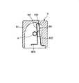
各図に示す留置針組立体1は、中空の外針2と、外針2の基端部に固定された外針ハブ3と、外針2内に挿通される内針4と、内針4の基端部に固定され、留置針組立体1を把持する手の親指を当接する指当部54を基端部に有する内針ハブ5と、外針ハブ3の側方部に、内腔71が外針2の内腔21と連通するように接続されたチューブ7とを有している。 The indwelling
外針2は、ある程度の可撓性を有するものが好ましく用いられる。外針2の構成材料は、樹脂材料、特に、軟質樹脂材料が好適であり、その具体例としては、例えば、PTFE、ETFE、PFA等のフッ素系樹脂、ポリエチレン、ポリプロピレン等のオレフィン系樹脂またはこれらの混合物、ポリウレタン、ポリエステル、ポリアミド、ポリエーテルナイロン樹脂、前記オレフィン系樹脂とエチレン−酢酸ビニル共重合体との混合物等が挙げられる。 As the outer needle 2, one having a certain degree of flexibility is preferably used. The constituent material of the outer needle 2 is preferably a resin material, in particular, a soft resin material. Specific examples thereof include fluorine resins such as PTFE, ETFE, and PFA, olefin resins such as polyethylene and polypropylene, and these. And mixtures of polyurethane, polyester, polyamide, polyether nylon resin, a mixture of the olefin resin and ethylene-vinyl acetate copolymer, and the like.
このような外針2は、その全部または一部が内部の視認性を有していてもよい。また、外針2の構成材料中には、例えば硫酸バリウム、炭酸バリウム、炭酸ビスマス、タングステン酸のようなX線造影剤を配合し、造影機能を持たせることもできる。 All or part of the outer needle 2 may have internal visibility. Further, in the constituent material of the outer needle 2, for example, an X-ray contrast agent such as barium sulfate, barium carbonate, bismuth carbonate, and tungstic acid can be blended to have a contrast function.
外針2の基端部には、例えば、カシメ、融着(熱融着、高周波融着等)、接着剤による接着等の方法により、外針ハブ3が液密に固定されている。 The
外針ハブ3は、略筒状の部主管36と、主管36の流路31から分岐した分岐流路32を有し、略筒状の側管37とを備えている。 The
前述したように、主管36の先端側には、外針2の基端部が固定されており、流路31は、その先端側において、外針2の内腔21と連通している。流路31(主管36)は、その軸線が外針2の中心軸と略一致するように配置されている。 As described above, the proximal end portion of the outer needle 2 is fixed to the distal end side of the
一方、分岐流路32(側管37)は、その軸線が、外針2の中心軸、すなわち、流路31の軸線に対して所定角度傾斜するように配置されている。この場合、分岐流路32は、分岐流路32の基端側が図1〜3中右側に位置するように傾斜している。なお、分岐流路32の軸線は、流路31の軸線に対して垂直であってもよい。 On the other hand, the branch channel 32 (side pipe 37) is arranged such that its axis is inclined at a predetermined angle with respect to the central axis of the outer needle 2, that is, the axis of the
また、チューブ7の先端部は、外針ハブ3の側管37に接続されている。これにより、チューブ7を介して、外針2に薬液等の液体を供給することができる。 The distal end portion of the tube 7 is connected to the
また、外針ハブ3の基端部には、リブ33が形成されている。このリブ33については、後に詳述する。 A
また、外針ハブ3の側方には、一対の翼12a、12bが外針ハブ3と一体的に形成されている。外針2および内針4を血管等に穿刺する際には、留置針組立体1を把持して穿刺し、外針2の先端が血管に入ったら、人指し指で後述する指当部916を押圧して外針ハブ3を押し進め、外針2のみを血管内に進めることができる。外針2を留置する際には、翼12a、12bを粘着テープ等により皮膚に固定する。 A pair of
外針2には、先端に鋭利な針先41を備える内針4が挿通される。留置針組立体1は、内針4を外針2に挿通し、外針2の先端開口(先端)22から針先41が突出した状態、すなわち、図1〜図3、図5、図6および図9に示す状態で使用される。以下、この状態を「組立状態」と言う。 An
内針4の長さは、組立状態としたとき、少なくとも針先41が外針2の先端開口22から突出する程度の長さとされる。
内針4は、中空針であってもよいが、中実針でもよい。The length of the
The
図示の構成では、内針4は、中空針であり、その途中の側部に図示しない孔部(側孔)が形成されている。これにより、内針4が血管を穿刺したときに、血液が内針4の中空部に流入し、その血液は、途中で、内針4の側部に形成された孔部から内針4と外針2との隙間に流入し、これによって血液のフラッシュバックをより早く確認することができるようになっている。 In the configuration shown in the drawing, the
なお、内針4は、中空部と中実部との双方を有する構成(例えば、中空針の内腔の一部を充填することにより、先端側を中空とし、基端側を中実とする構成等)とすることもできるが、その全体を一つの部材で構成することにより、内針4のコストの削減を図ることができる。 The
また、内針4は、その外径が一定のものでもよく、また、その外径が異なる複数の部分を有しているものでもよい。 Further, the
このような内針4の構成材料としては、例えば、ステンレス鋼、アルミニウムまたはアルミニウム合金、チタンまたはチタン合金のような金属材料が挙げられる。 Examples of the constituent material of the
内針4の基端部には、内針ハブ5が固定されている。すなわち、内針ハブ5は、内針ハブ本体部50を有しており、内針4の基端部は、その内針ハブ本体部50に固定されている。内針4の内針ハブ5(内針ハブ本体部50)に対する固定方法は、例えば、嵌合、カシメ、融着、接着剤による接着等の方法、あるいはこれらを併用した方法が挙げられる。なお、図示の構成では、内針4が中空であるので、血管に穿刺した際に逆流する血液が内針ハブ5の基端部から飛び出さないように封止されている。 An inner needle hub 5 is fixed to the proximal end portion of the
また、内針ハブ本体部50は、その先端部に、組立状態で、後述するプロテクタ9の基端部が挿入され、後述する連結部材20が収納されるプロテクタ挿入部(連結部材収納部)51を有している。プロテクタ9および連結部材20は、それぞれ、プロテクタ挿入部51に対して移動し得るようになっている。 Further, the inner needle hub
そして、この内針ハブ5の基端部には、指当部54が設けられている。なお、指当部54については、後で詳述する。 A
このような内針ハブ5および前述した外針ハブ3は、それぞれ、好ましくは透明(無色透明)、着色透明または半透明の樹脂で構成され、内部の視認性が確保されている。これにより、外針2が血管を確保した際、前述した内針4を介して流入する血液のフラッシュバックを目視で確認することができる。 Each of the inner needle hub 5 and the
外針ハブ3、内針ハブ5および翼12a、12bの構成材料としては、特に限定されない。なお、外針ハブ3および翼12a、12bの構成材料としては、それぞれ、例えば、ポリエチレン、ポリプロピレン、エチレン−酢酸ビニル共重合体等のポリオレフィン、ポリウレタン、ポリアミド、ポリエステル、ポリカーボネート、ポリブタジエン、ポリ塩化ビニル、ポリアセタール等の各種樹脂材料が挙げられる。内針ハブ5の構成材料については、後で述べる。 The constituent materials of the
チューブ7は、可撓性を有しており、前述したように、その先端部が外針ハブ3の側管37に接続されている。チューブ7の基端部には、流路が2つに分岐した分岐部が設けられており、その一方にコネクタ72が装着され、他方にコネクタ73が装着されている。各コネクタ72および73には、それぞれ、例えば、投与する輸液(薬液)を供給する輸液ラインの端部に装着されたコネクタ、薬液を収納したシリンジの口部等が接続される。 The tube 7 has flexibility, and the distal end portion thereof is connected to the
なお、チューブ7の構成材料としては、特に限定されないが、例えば、ポリエチレン、ポリプロピレン、エチレン−酢酸ビニル共重合体等のポリオレフィン、ポリ塩化ビニル、ポリブタジエン、ポリアミド、ポリウレタン、ポリエステル等が挙げられる。 In addition, although it does not specifically limit as a constituent material of the tube 7, For example, polyolefin, such as polyethylene, a polypropylene, an ethylene-vinyl acetate copolymer, polyvinyl chloride, polybutadiene, polyamide, polyurethane, polyester, etc. are mentioned.
また、留置針組立体1は、外針ハブ3の流路31に、その流路31を封止する封止手段として、円柱状(ブロック状)のシール部材(図示せず)を有している。このシール部材は、主管36の流路31の分岐流路32よりも基端側に設置(固定)されている。そして、本実施形態では、シール部材は、分岐流路32の近傍に配置されている。 The indwelling
このシール部材には、内針4を挿通可能で、かつ、挿通された内針4を抜去した際に閉塞する孔またはスリットが形成されている。本実施形態では、シール部材の略中央に、そのシール部材の長手方向に沿って貫通するスリット(図示せず)が形成されている。 The seal member is formed with a hole or a slit through which the
スリットは、その形状が一文字状をなしている。これにより、閉状態のスリットを容易に開状態とすることができる。よって、内針4がシール部材(スリット)を円滑に挿通することができ、すなわち、後述するように内針4をガイドとして外針2を進めるとき、内針4の外面とスリットの内面との間の摩擦抵抗を低減することができる。このため、留置針組立体1の穿刺操作時の操作性がより向上する。 The slit has a single letter shape. Thereby, the closed slit can be easily opened. Therefore, the
シール部材は、組立状態で、スリットに内針4が挿通され、かつ、挿通された内針4を抜去した際には、スリットがシール部材の自らの弾性力(復元力)により閉塞する自己閉塞性を有するものである。これにより、内針4を抜去した際に、外針ハブ3の基端からの液漏れを防止することができるとともに、外針ハブ3内の無菌性を維持することもできる。 When the
このようなシール部材の構成材料としては、例えば、天然ゴム、イソプレンゴム、ブチルゴム、ブタジエンゴム、スチレン−ブタジエンゴム、ウレタンゴム、ニトリルゴム、アクリルゴム、フッ素ゴム、シリコーンゴムのような各種ゴム材料(特に加硫処理したもの)や、ウレタン系、ポリエステル系、ポリアミド系、オレフィン系、スチレン系等の各種熱可塑性エラストマー、あるいはそれらの混合物等の各種弾性材料が挙げられる。 Examples of the constituent material of such a seal member include various rubber materials such as natural rubber, isoprene rubber, butyl rubber, butadiene rubber, styrene-butadiene rubber, urethane rubber, nitrile rubber, acrylic rubber, fluorine rubber, and silicone rubber ( In particular, those obtained by vulcanization treatment), various thermoplastic elastomers such as urethane-based, polyester-based, polyamide-based, olefin-based, styrene-based, and mixtures thereof, and various elastic materials.
また、留置針組立体1には、スリットの内面と内針4の外面との間の摩擦抵抗を低減する摩擦低減処理が施されているのが好ましい。 In addition, the indwelling
この摩擦低減処理としては、例えば、スリットの内面および内針4の外面(外周面)の少なくとも一方の面に潤滑剤を付与する処理、スリットの内面に低摩擦材料で構成される層(低摩擦層)を形成すること等が挙げられる。 Examples of the friction reducing process include a process of applying a lubricant to at least one of the inner surface of the slit and the outer surface (outer peripheral surface) of the
このような摩擦低減処理により、内針4をガイドとして外針2を進めるとき、内針4とシール部材との間の摩擦抵抗を確実に低減することができる。これにより、外針2を円滑に移動させることができ、留置針組立体1が穿刺操作時の操作性に優れたものとなる。 By such a friction reduction process, when the outer needle 2 is advanced using the
また、留置針組立体1は、内針4を外針2から抜去した際に、内針4の少なくとも針先41を覆うプロテクタ9を有している。以下、このプロテクタ9について説明する。 The indwelling
プロテクタ9は、組立状態で、内針ハブ5のプロテクタ挿入部51に、挿入(配設)されている。 The
このプロテクタ9は、外針ハブ3に対して着脱自在に連結されるようになっており、図4、図5および図7に示すように、プロテクタ本体91と、プロテクタ本体91内に設けられた連結部材92とを有している。 The
プロテクタ本体91の先端部には、組立状態で外針ハブ3の基端部が挿入される有底の穴部911が形成されている。 A bottomed
プロテクタ本体91の構成材料は、特に限定されず、例えば、外針ハブ3および内針ハブ5の構成材料として挙げたものと同様のものを用いることができる。 The constituent material of the protector
また、プロテクタ本体91の穴部911の基端側には、連結部材92が収納されている。すなわち、プロテクタ本体91には、穴部911の底壁を構成する壁部912と、壁部912の基端側に配置された壁部913とが形成されており、連結部材92は、これら壁部912と壁部913との間に設置されている。 A connecting
図5、図7および図8に示すように、連結部材92は、弾性を有し、外針ハブ3のリブ33と係合し得る板状の突出片924を有している。プロテクタ9は、組立状態では、その穴部911に外針ハブ3の基端部が挿入された状態で、連結部材92の突出片924と外針ハブ3のリブ33とが係合することにより、外針ハブ3に対して着脱自在に連結される。 As shown in FIGS. 5, 7, and 8, the connecting
本実施形態では、連結部材92は、全体形状として略V字状をなしており、弾性を有する帯状の板部材を略V字状に曲げることにより形成されたもの(板バネ)である。具体的には、連結部材92は、第1の部位921と、第1の部位921の図8中上側に接続され、この第1の部位921とで略V字形状を形成する第2の部位922と、第1の部位921の図8中下側に配置された第3の部位923と、第3の部位923の基端から図8中上側に向かって突出する突出片924と、第1の部位921の途中であって基端側に配置されたシャッター部925とを有している。また、第2の部位922の図8中下側の部位は、上側に向かって湾曲または屈曲している。また、突出片924の後述するリブ33の摺動面331に対向する対向面926は、内針4の中心軸O1に対して略垂直である。In the present embodiment, the connecting
この連結部材92は、第1の部位921と第2の部位922との開き角度が変化することにより、突出片924とリブ33とが係合した第1の状態と、突出片924とリブ33との係合が外れた第2の状態とを採り得るようになっている。 The connecting
すなわち、図5、図6および図9に示すように、組立状態では、連結部材92は、開き角が小さくなるように折り畳んだ状態で収納され、第1の部位921が内針4の外周面に当接することにより、第1の状態に保持されている。この状態では、プロテクタ9は、外針ハブ3に対して連結されている。また、プロテクタ9および外針ハブ3は、内針4および内針ハブ5に対して、内針4の長手方向に相対的に移動可能である。 That is, as shown in FIGS. 5, 6, and 9, in the assembled state, the connecting
この状態から、内針ハブ5をプロテクタ9に対し基端方向へ移動させ、内針4の針先41が連結部材92の第1の部位921の基端側に至ると、図7および図10に示すように、連結部材92は、自らの弾性力により開くとともに、後述する連結部材20を介して基端方向に引っ張られて移動し、第2の状態となる。連結部材92の復元により突出片924が移動する方向は、内針4の中心軸O1に対して略垂直な方向である。この状態では、プロテクタ9と外針ハブ3との連結は、解除されている。また、連結部材92のシャッター部925が、内針4の中心軸O1上の針先41の先端側に位置し、これにより、針先41が連結部材92を超えて先端方向へ移動するのが阻止される。なお、内針ハブ5を基端方向へさらに移動させると、プロテクタ9は、後述する連結部材20を介して基端方向に引っ張られて移動し、外針ハブ3から離脱する。From this state, when the inner needle hub 5 is moved in the proximal direction with respect to the
連結部材92の構成材料としては、特に限定されず、例えば、上述した外針ハブ3、内針ハブ5と同様な各種樹脂材料や、ステンレス鋼、アルミニウムまたはアルミニウム合金、チタンまたはチタン合金、銅または銅合金等の各種金属材料が挙げられる。 The constituent material of the connecting
なお、連結部材92の一部は、例えば、カシメ、埋入、融着、接着剤による接着等の方法により、プロテクタ本体91に固定されていてもよい。また、連結部材92は、図示の構成に限らず、他の形状・構造のものであってもよい。 Note that a part of the connecting
また、プロテクタ本体91の先端部には、指当部916が突出形成されている。プロテクタ本体91と指当部916とは、一体的に形成されている。また、指当部916は、上方向に向かって突出している。この指当部916を指で先端方向に押圧することにより、内針4に対して外針2を先端方向に移動させることができる。 In addition, a
なお、プロテクタ本体91と指当部916とを別部材で形成し、それらを接合してもよい。この場合、指当部916の構成材料としては、特に限定されないが、例えば、外針ハブ3の構成材料として挙げたものと同様のものを用いることができる。また、指当部916は、他の部位、例えば、外針ハブ3に突出形成されていてもよい。 In addition, the protector
また、図4、図5および図7に示すように、留置針組立体1は、プロテクタ9が内針4の針先41を覆ったときに当該プロテクタ9が針先41から脱落するのを防止する脱落防止手段の機能と、プロテクタ9と内針ハブ5とを連結する連結手段の機能とを有する連結部材20を有している。 As shown in FIGS. 4, 5, and 7, the indwelling
この連結部材20は、プロテクタ9のプロテクタ本体91と内針ハブ5とを連結するよう構成されている。これにより、内針ハブ5を基端方向に移動させると、プロテクタ9が連結部材20を介して基端方向に引っ張られるようになっている。 The connecting
また、連結部材20は、蛇腹状をなしており、このため伸縮自在である。そして、連結部材20は、最大に伸長した状態(伸びきった状態)において、内針4の針先41が連結部材92のシャッター部925よりも基端側に位置し、かつ、針先41がプロテクタ本体91内に収納される(プロテクタ本体91から脱落しない)程度の長さを有している。 Further, the connecting
このように、連結部材20は、プロテクタ本体91と内針ハブ5とを連結し、最大に伸長した状態において針先41がプロテクタ本体91内に収納される程度の長さを有しているので、プロテクタ9が内針4の針先41から脱落するのが確実に防止され、よって、プロテクタ9が針先41を覆った状態を確実に維持することができる。このため、内針4等の廃棄処理等に際し、その作業者等が誤って針先41で手指等を刺すという事故が確実に防止され、安全性が高い。 As described above, the connecting
また、連結部材20は、組立状態では収縮し、すなわち、折り畳まれ、内針4が外針2から抜去され、プロテクタ9が針先41を覆った状態では伸長する、すなわち、展開する。 Further, the connecting
このような連結部材20は、組立状態で収縮し、この収縮した状態で、内針ハブ5のプロテクタ挿入部51のプロテクタよりも基端側に収納される。これにより、穿刺操作時に連結部材20が邪魔にならず、留置針組立体1の操作性が向上する。また、留置針組立体1の小型化を図ることができるという利点もある。 Such a connecting
また、連結部材20が収縮した状態および伸長した状態で、内針4が当該連結部材20を貫通している。これにより、内針4が、連結部材20の伸縮するときの当該連結部材20のガイドとして機能する。よって、例えば、留置針組立体1を組立状態とする(製造する)とき、連結部材20が不本意な状態で収縮する、すなわち、内針ハブ5に収納されずに収縮するのを確実に防止することができる。 Further, the
また、連結部材20は、その自然状態に戻ろうとする自己復元性を有しており、自然状態よりも収縮した状態では、その復元力により、伸長する方向に付勢する付勢手段として機能し、また、自然状態よりも伸長した状態では、その復元力により、収縮する方向に付勢する付勢手段として機能する。「自然状態」とは、連結部材20に外力が付与されていない状態をいう。 Further, the connecting
なお、連結部材20は、プロテクタ9と内針4とを連結するよう構成されていてもよい。 The connecting
図4、図5、図7、図9および図10に示すように、この留置針組立体1の外針ハブ3は、その基端部に、前記プロテクタ9の連結部材92の突出片924と係合し得る凸部として、リブ33を有している。 As shown in FIGS. 4, 5, 7, 9, and 10, the
リブ33は、外針ハブ3の基端部の外周面に、その周方向に沿って形成されており、図示の構成では、環状をなしている。 The
このリブ33は、内針4の中心軸(軸)O1に対して傾斜し、突出片924が摺動する摺動面331を有しており、連結部材92が、図5、図6および図9に示す第1の状態から図7および図10に示す第2の状態に移行する際、連結部材92の突出片924は、その摺動面331に沿って摺動するよう構成されている。すなわち、連結部材92は、内針4を外針2から抜去する際、その第1の部位921が内針4の外周面から離間し、復元し、連結部材92が復元する際、突出片924がリブ33の摺動面331に沿って摺動し、第2の状態になる。The
これにより、内針4を外針2から抜去し、プロテクタ9を外針ハブ3から離脱させる際、抵抗を低減することができる。これによって、前記内針4を外針2から抜去し、プロテクタ9を外針ハブ3から離脱させる操作を円滑かつ確実に行うことができる。 Thereby, when extracting the
また、摺動面331が傾斜しているので、突出片924とリブ33の摺動面331との接触部分の面積は、小さく、これにより、突出片924とリブ33のの摺動面331との摺動抵抗は、小さい。これによって、より円滑に、リブ33の摺動面331に沿って突出片924が摺動することができる。 Further, since the sliding
リブ33の摺動面331の内針4の中心軸O1に対する傾斜角度(中心軸O1とのなす角)θは、90°未満であるが、30〜85°程度であるのが好ましく、45〜80°程度であるのがより好ましい。
これにより、より円滑に、プロテクタ9を外針ハブ3から離脱させることができる。The theta (angle between the center axis O1) angle of inclination with respect to the center axisO 1 of the
Thereby, the
ここで、組立状態から内針ハブ5をプロテクタ9に対し基端方向へ移動させてゆき、内針4を外針2から抜去する際において、連結部材92が第1の状態のときに要する力をF1、内針4の針先41が連結部材92の基端側に移動した瞬間から連結部材92の突出片924とリブ33との係合が外れるまで、すなわち、連結部材92が第1の状態から第2の状態に移行するときに要する力をF2としたとき、下記の条件を満足するように、傾斜角度θを設定するのが好ましい。 Here, when the inner needle hub 5 is moved in the proximal direction with respect to the
すなわち、F2が、2×F1以下であるのが好ましく、1.5×F1以下であるのがより好ましく、F1以下であるのがさらに好ましい。 That is, F2 is preferably 2 × F1 or less, more preferably 1.5 × F1 or less, and even more preferably F1 or less.
そして、特に、F2とF1とが略等しくなるように、傾斜角度θを設定するのが好ましい。
これにより、より円滑に、プロテクタ9を外針ハブ3から離脱させることができる。In particular, it is preferable to set the inclination angle θ so that F2 and F1 are substantially equal.
Thereby, the
なお、F1のうちの大部分は、内針4の外周面と連結部材92の第1の部位921との摩擦抵抗に対抗する力である。また、F2のうちの大部分は、連結部材92の突出片924とリブ33の摺動面331との摩擦抵抗に対抗する力である。 Most of F1 is a force that opposes the frictional resistance between the outer peripheral surface of the
また、リブ33の高さは、本実施形態では一定であるが、突出片924がリブ33の摺動面331に沿って摺動する際の移動方向に向かって漸減していてもよい。リブ33の高さが漸減している場合は、より円滑かつ確実に、連結部材92を第2の状態にすることができる。 In addition, the height of the
なお、外針ハブ3のリブ33の摺動面331と、連結部材92の突出片924の対向面926とのいずれか一方、または、双方に、例えば、シリコーンオイル、界面活性剤等の潤滑剤が塗布されているのが好ましい。これにより、突出片924とリブ33の摺動面331との摺動抵抗が低減し、より円滑に、リブ33の摺動面331に沿って連結部材92の突出片924が摺動することができる。 Note that a lubricant such as silicone oil or a surfactant is applied to one or both of the sliding
また、連結部材92の第1の部位921の内針4の外周面と接触する部位にも、潤滑剤が塗布されているのが好ましい。これにより、内針4の外周面と第1の部位921との摩擦抵抗が低減し、プロテクタ9に対する内針4の移動をより円滑に行うことができる。 In addition, it is preferable that a lubricant is also applied to a portion of the
さて、図2および図5に示すように、この留置針組立体1では、内針ハブ5の基端部に、指当部54が設けられている。この指当部54は、内針ハブ本体部50の基端面53より基端方向に突出し、指当部54(内針ハブ5の基端部)に親指を当接したときに装着した医療用手袋に対して滑り難い材料(内針ハブ本体部50よりも滑り難い材料)で形成された凸部55と、基端面53の凸部55が形成されていない部位とで構成されている。以下、医療用手袋を単に「手袋」とも言う。 Now, as shown in FIGS. 2 and 5, in this
ここで、医師(使用者)は、留置針組立体1の外針2を患者に留置する際、手袋を装着し、手指で組立状態の留置針組立体1を把持して、外針2および内針4を血管等に穿刺する穿刺操作を行う。そして、この穿刺操作の際、医師は、例えば、図3に示す方法で留置針組立体1を把持することがある。 Here, when the doctor (user) places the outer needle 2 of the
この持ち方は、本明細書では、「ウイングポート持ち」と呼び、親指を指当部54(内針ハブ5の基端部)に当接し、残りの指のうちのいずれか(図示の構成では中指)を留置針組立体1の先端側、すなわち、外針ハブ3の翼12aに当接し、これにより留置針組立体1を長手方向から挟み付けて把持する。なお、翼12a、12bを有していない留置針組立体を使用する場合でも、例えば中指を、外針ハブの先端や先端部のテーパ面等、その留置針組立体の先端側に当接させて前記ウイングポート持ちを行うことができる。 In this specification, this holding method is referred to as “holding a wing port”, and the thumb is brought into contact with the finger contact portion 54 (the base end portion of the inner needle hub 5), and one of the remaining fingers (the illustrated configuration) The middle finger) is brought into contact with the distal end side of the
このようなウイングポート持ちで留置針組立体1を把持する場合、前記凸部55を設けることにより、手袋を装着した親指が指当部54(内針ハブ5の基端部)から滑ることを防止することができ、これにより、穿刺操作を容易かつ安全に行なうことができる。 When the
前記凸部55は、基端面53に固定されている。凸部55の基端面53に対する固定方法としては、例えば、嵌合、融着、インサート成形、接着剤による接着等の方法、あるいはこれらを併用した方法が挙げられる。 The
また、凸部55は、基端面53の一部から隆起している。図示の構成では、内針4の中心軸O1の方向から見たときの凸部55の形状は、円形をなしており、その凸部55は、基端面53の中心部に配置されている。これにより、親指が指当部54から滑ることをより確実に防止することができる。Further, the
この凸部55の寸法は、特に限定されず、諸条件に応じて適宜設定されるが、内針4の中心軸O1に対して垂直な平面に凸部55を投影したときの面積(投影面積)をa、前記平面に指当部54の全体(基端面53の全体)を投影したときの面積、すなわち、基端面53の凸部55が設けられていない部位および凸部55を投影したときの面積をbとしたとき、bに対するaの比率(a/b)は、0.01〜0.8程度であることが好ましく、0.1〜0.3程度であることがより好ましい。The dimension of the
また、凸部55の高さ(中心軸O1の方向の長さ)は、0.1〜5mm程度であることが好ましく、0.3〜2mm程度であることがより好ましい。また、凸部55の前記投影面積aは、0.2〜20mm2程度であることが好ましく、0.7〜13mm2程度であることがより好ましい。The height (center axis direction of the length of theO 1) of the
ここで、医療用の手袋は、柔らかく、手にフィットすることと共に、強度が要求される。このため、手袋の構成材料としては、例えば、ポリ塩化ビニル(PVC)、天然ゴムラテックス、ニトリル等が用いられている。この留置針組立体1では、このような手袋の各構成材料に応じ、凸部55の構成材料として、適宜、滑り難い材料を選択することで、手袋を装着した親指が指当部54から滑ることを防止する。 Here, a medical glove is soft and needs to be strong enough to fit in the hand. For this reason, as a constituent material of gloves, for example, polyvinyl chloride (PVC), natural rubber latex, nitrile and the like are used. In the
また、凸部55の構成材料としては、手袋に対して滑り難い材料(内針ハブ本体部50よりも滑り難い材料)であれば特に限定されず、諸条件に応じて適宜設定されるが、その凸部55の構成材料としては、例えば、イソプレンゴム、シリコーンゴム、エチレン−酢酸ビニル共重合体、ポリウレタン等が好ましく、イソプレンゴム、シリコーンゴムがより好ましい。 In addition, the constituent material of the
また、凸部55の基端面(基端面側の部位)には、図示しない複数の微小な凹凸が形成されていることが好ましい。これにより、親指が指当部54から滑ることをより確実に防止することができる。前記微小な凹凸の形成方法としては、特に限定されず、例えば、エンボス加工、梨地加工、ショットブラスト(例えばシリカ粒子を衝突させる)等が挙げられる。 In addition, it is preferable that a plurality of minute irregularities (not shown) are formed on the base end face (part on the base end face side) of the
また、内針ハブ5の内針ハブ本体部50は、内針4や、その他、プロテクタ9等との組み立てが容易で、血液のフラッシュバックが見える程度の透明性を有し、また、把持部としても使用されることから、比較的硬いことが要求される。 Further, the inner
この内針ハブ本体部50の構成材料としては、例えば、ポリカーボネート、ポリプロピレン等を用いることが好ましい。ポリカーボネートを用いると、透明性に優れ、硬く、溶剤接着を行うことができる等、組み立てが容易である。また、ポリプロピレンを用いると、耐薬品性に優れ、生体適合性も良い。 As a constituent material of the inner
なお、組立状態の留置針組立体1の外針ハブ3の先端と凸部55(指当部54)の基端との間の長さ(距離)Lは、20〜80mm程度であることが好ましく、30〜60mm程度であることがより好ましい。これにより、ウイングポート持ちを容易に行うことができる。 The length (distance) L between the distal end of the
次に、留置針組立体1の使用方法の一例(血管に穿刺する場合)(作用)について、詳細に説明する。 Next, an example of how to use the indwelling needle assembly 1 (when puncturing a blood vessel) (action) will be described in detail.
前提として、医師は、医療用の手袋を装着する。この工程は、後述する穿刺操作を行う前までに行えばよい。 As a premise, doctors wear medical gloves. This step may be performed before a puncture operation described later.
[1] 留置針組立体1を用意し、組立状態(図1、図2、図5、図6、図9参照)とし、予めコネクタ72に、輸液ラインの端部に装着されたコネクタを接続し、輸液ラインからの輸液を供給可能とする。 [1] An
なお、このとき、チューブ7または輸液ライン上の所定箇所を例えばクランプ(流路開閉手段の一例)により挟み、その内腔を閉塞しておく。 At this time, a predetermined location on the tube 7 or the infusion line is sandwiched by, for example, a clamp (an example of a channel opening / closing means), and the lumen is closed.
[2] 次に、前記クランプ等によるチューブ7または輸液ラインの閉塞を解除し、輸液ラインからの輸液をチューブ7を介して外針ハブ3内に導入する。 [2] Next, the block of the tube 7 or the infusion line by the clamp or the like is released, and the infusion from the infusion line is introduced into the
外針ハブ3内に導入された輸液は、分岐流路32およびシール部材より先端側の流路31を満すとともに、外針2の内腔21に導入され、これにより、外針2の内腔21が輸液によりプライミングされる。このとき、輸液の一部は、外針2の先端開口22より流出する。 The infusion solution introduced into the
[3] 以上のようにしてプライミングが完了したら、チューブ7または輸液ラインをクランプ等により再び閉塞しておき、留置針組立体1を前述したウイングポート持ちで把持する。 [3] When priming is completed as described above, the tube 7 or the infusion line is closed again with a clamp or the like, and the
[4] 次に、一体化された外針2および内針4を患者の血管(静脈または動脈)(生体)に穿刺する。 [4] Next, the integrated outer needle 2 and
外針2により血管が確保されると、血管の内圧(血圧)により血液が、内針4を介して外針2の内腔21を基端方向へ逆流するので、視認性を有する外針2、外針ハブ3、内針ハブ5またはチューブ7のうちの少なくとも1箇所において、これを確認することができる。 When a blood vessel is secured by the outer needle 2, blood flows backward through the
そして、これを確認した後、さらに、内針4をガイドとし、内針4に沿って、外針2を微小距離先端方向へ進める。 Then, after confirming this, the outer needle 2 is advanced toward the distal end by a minute distance along the
また、このような血管への穿刺に際しては、外針2の内腔21が輸液によりプライミングされているため、誤って血管内に気泡が侵入することが確実に防止され、安全性が極めて高い。 Further, when such a blood vessel is punctured, since the
[5] 外針2により血管が確保されたら(外針2が目的位置まで移動したら)、外針2または外針ハブ3を一方の手で固定し、他方の手で内針ハブ5を把持して基端方向へ引っ張る。これにより、内針4が外針2から抜去される動作から、プロテクタ9が外針ハブ3から離脱するまでのすべての各操作(動作)が、順次、連続して行なわれる。すなわち、まずは、内針4が基端方向へ移動し、外針2から抜去される。 [5] When the blood vessel is secured by the outer needle 2 (when the outer needle 2 moves to the target position), the outer needle 2 or the
[6] さらに、内針4が基端方向へ移動し、針先41がスリット内を通過すると、自己閉塞性を有するシール部材は、自らの弾性力によりスリットを閉塞する。これにより、スリットを介して液漏れが生じることはなく、また、外針ハブ3内や輸液ラインの無菌性も確保される。 [6] Further, when the
[7] さらに、内針4が基端方向へ移動し、針先41が連結部材92の第1の部位921の基端側に至ると、図7および図10に示すように、連結部材92は、自らの弾性力により開くとともに、連結部材20を介して基端方向に引っ張られて移動し、第2の状態となる。 [7] Further, when the
この場合、前述したように、連結部材92の復元により突出片924が移動する方向は、内針4の中心軸O1に対して略垂直な方向であるが、プロテクタ9は、連結部材20を介して基端方向に引っ張られて移動するので、それとともに連結部材92も基端方向に移動し、これにより、突出片924がリブ33の摺動面331に沿って摺動し、連結部材92は、第2の状態になる。このように、連結部材92が第2の状態になると、内針4の針先41が再び先端方向へ戻るように移動しようとしても、針先41が連結部材92のシャッター部925に当接し、戻ることはできない。In this case, as described above, the direction in which the projecting
[8] さらに、内針ハブ5が基端方向へ移動し、これにより、プロテクタ9は、連結部材20を介して基端方向に引っ張られて移動し、外針ハブ3から分離される(離脱する)。 [8] Further, the inner needle hub 5 moves in the proximal direction, whereby the
連結部材20は、最大に伸長した状態において針先41がプロテクタ本体91内に収納される程度の長さを有しているので、プロテクタ9が針先41から脱落するのを確実に防止することができ、よって、プロテクタ9が針先41を覆った状態を確実に保持することができる。 Since the connecting
このようにして外針2から内針4を抜去した後は、内針4および内針ハブ5は不用となるため、廃棄処分に供される。 After the
内針4は、その針先41がプロテクタ9で覆われており、特に、針先41が連結部材92のシャッター部925を超えてそれより先端側へ移動し、プロテクタ9の先端から突出することがないため、廃棄処理を行う者等が針先41で誤って手指等を刺すという事故が防止される。 The
[9] 次に、翼12a、12bを粘着テープ等により皮膚に固定するとともに、前記クランプによるチューブ7または輸液ラインの閉塞を解除し、輸液の供給を開始する。 [9] Next, the
輸液ラインから供給される輸液は、コネクタ72、チューブ7、外針ハブ3および外針2の各内腔を経て、患者の血管内に注入される。 The infusion supplied from the infusion line is injected into the blood vessel of the patient through the lumens of the
以上説明したように、この留置針組立体1によれば、凸部55により、留置針組立体1をウイングポート持ちで把持する手の親指が指当部54(内針ハブ5の基端部)から滑ることを防止(または抑制)することができる。これにより、手技に集中することができ、穿刺操作を容易かつ安全に行なうことができる。 As described above, according to the
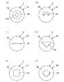
なお、本実施形態における凸部55の他の構成例としては、例えば、図11(a)〜(f)、図12(g)〜(k)に示すものが挙げられる。 In addition, as another example of a structure of the
図11および図12は、本実施形態の留置針組立体における他の構成例を示す図であり、図11(a)〜(f)、図12(g)〜(j)は、留置針組立体の背面図、図12(k)は、凸部の断面図である。なお、以下では、図11(a)〜(f)、図12(g)〜(j)の上側を「上」、下側を「下」、図12(k)中の左側を「先端」、右側を「基端」、上側を「上」、下側を「下」として説明を行う。 FIGS. 11 and 12 are diagrams showing other configuration examples of the indwelling needle assembly of the present embodiment. FIGS. 11 (a) to 11 (f) and FIGS. 12 (g) to 12 (j) are indwelling needle assemblies. A solid rear view, FIG. 12 (k), is a cross-sectional view of a convex portion. In the following, the upper side of FIGS. 11A to 11F and FIGS. 12G to 12J is “upper”, the lower side is “lower”, and the left side in FIG. The right side is “base end”, the upper side is “upper”, and the lower side is “lower”.
図11(a)に示す留置針組立体1では、凸部55は、基端面53の一部から隆起し、基端面53の中心部に配置されている。内針4の中心軸O1の方向から見たときの凸部55の形状は、円環状をなしている。すなわち、凸部55の中心部には、無底の凹部551が設けられている。In the
図11(b)に示す留置針組立体1では、凸部55は、基端面53の一部から隆起し、基端面53の中心部に配置されている。内針4の中心軸O1の方向から見たときの凸部55の形状は、円環を半分にした形状、すなわち、下側が凹となる湾曲した線状をなしている。In the
図11(c)に示す留置針組立体1では、凸部55は、基端面53の一部から隆起し、基端面53の中心部に配置されている。内針4の中心軸O1の方向から見たときの凸部55の形状は、直線状をなしている。In the
図11(d)に示す留置針組立体1では、凸部55は、基端面53の一部から隆起し、基端面53の中心部に配置されている。内針4の中心軸O1の方向から見たときの凸部55の形状は、直角二等辺三角形をなしている。なお、この凸部55は、直角の頂点が下方を向くように配置されている。In the
図11(e)に示す留置針組立体1では、凸部55は、基端面53の一部から隆起し、基端面53の中心部に配置されている。内針4の中心軸O1の方向から見たときの凸部55の形状は、正方形をなしている。なお、凸部55の形状は、5角以上の多角形でもよい。In the
図11(f)に示す留置針組立体1では、凸部55は、基端面53の一部から隆起し、基端面53の中心部に配置されている。内針4の中心軸O1の方向から見たときの凸部55の形状は、十字状をなしている。In the
図12(g)に示す留置針組立体1では、凸部55は、基端面53の一部から隆起している。内針4の中心軸O1の方向から見たときの凸部55の形状は、放射状をなしている。すなわち、凸部55は、基端面53の中心から放射状に設けられた複数の単位凸部552で構成されており、凸部55の中心部には、凹部553が設けられている。In the
図12(h)に示す留置針組立体1では、凸部55は、基端面53の一部から隆起し、基端面53の中心部に配置されている。内針4の中心軸O1の方向から見たときの凸部55の形状は、円環(環)の上側部分(一部)を除去した形状をなしている。In the
図12(i)に示す留置針組立体1では、凸部55は、基端面53の一部から隆起し、基端面53の中心部に配置されている。内針4の中心軸O1の方向から見たときの凸部55の形状は、円形をなしている。また、凸部55の上側部分(図中、斜線で示す部分)は、それよりも下側の部分とは異なる色に着色されている。In the
図12(j)に示す留置針組立体1では、凸部55は、基端面53の一部から隆起している。この凸部55は、2つの単位凸部554および555で構成されている。 In the
内針4の中心軸O1の方向から見たときの単位凸部554の形状は、円環(環)を半分にした形状、すなわち、下側が凹となる湾曲した線状をなしている。この単位凸部554は、基端面53の上側に、その外周に沿って配置されている。The shape of the unit
一方、内針4の中心軸O1の方向から見たときの単位凸部555の形状は、円形をなしている。この単位凸部555は、基端面53の下側に配置されている。On the other hand, the shape of the unit
また、単位凸部554の中心軸O1の方向の長さは、単位凸部555のその長さよりも長く設定されおり、単位凸部554の基端面は、単位凸部555の基端面よりも基端側に位置している。Further, the length of the unit
これにより、留置針組立体1をウイングポート持ちで把持したとき、親指の先端側が単位凸部554に当接し、親指の腹付近が単位凸部555に引っ掛かるので、親指が指当部54から滑ることをより確実に防止することができる。 Thus, when the
図12(k)に示す留置針組立体1では、凸部55は、基端面53の一部から隆起し、基端面53の中心部に配置されている。内針4の中心軸O1の方向から見たときの凸部55の外形形状は、円形をなしている。そして、凸部55の中心部には、有底の凹部556が設けられている。In the
ここで、凸部55による模様が所定の情報を有するように、すなわち、所定の目印となるように構成してもよい。例えば、図11(b)および(d)に示す凸部55は、それぞれ、その下方が所定の位置(方向)を示すように構成することができ、図12(h)および(i)に示す凸部55は、それぞれ、その上方が所定の位置を示すように構成することができる。 Here, you may comprise so that the pattern by the
以上、本発明の留置針組立体を、図示の実施形態に基づいて説明したが、本発明はこれに限定されるものではなく、各部の構成は、同様の機能を有する任意の構成のものに置換することができる。また、本発明に、他の任意の構成物や、工程が付加されていてもよい。 As mentioned above, although the indwelling needle assembly of this invention was demonstrated based on embodiment of illustration, this invention is not limited to this, The structure of each part is set to the thing of the arbitrary structures which have the same function. Can be replaced. Moreover, other arbitrary structures and processes may be added to the present invention.
なお、本発明の留置針組立体は、血管内に挿入して使用されるものに限定されず、例えば、腹腔内、胸腔内、リンパ管内、脊柱管内等、生体に挿入して使用されるものに適用することもできる。 The indwelling needle assembly of the present invention is not limited to the one used by being inserted into a blood vessel. It can also be applied to.
また、本発明では、プロテクタは、図示の構成のものに限定されず、外針ハブに対して着脱自在に連結されるものであればよい。特に、内針を外針から抜去した際に、内針の少なくとも針先を覆うものであれば、種々の構成のものを用いることができる。 Moreover, in this invention, a protector is not limited to the thing of the structure of illustration, What is necessary is just to be connected with an outer needle hub so that attachment or detachment is possible. In particular, when the inner needle is removed from the outer needle, various configurations can be used as long as they cover at least the needle tip of the inner needle.
また、本発明では、翼12a、12bが省略されていてもよい。
また、本発明では、側管37やチューブ7が省略されていてもよい。In the present invention, the
In the present invention, the
1 留置針組立体
2 外針
21 内腔
22 先端開口
3 外針ハブ
31 流路
32 分岐流路
33 リブ
331 摺動面
36 主管
37 側管
4 内針
41 針先
5 内針ハブ
50 内針ハブ本体部
51 プロテクタ挿入部
53 基端面
54 指当部
55 凸部
551、553、556 凹部
552、554、555 単位凸部
7 チューブ
71 内腔
72、73 コネクタ
9 プロテクタ
91 プロテクタ本体
911 穴部
912、913 壁部
916 指当部
92 連結部材
921 第1の部位
922 第2の部位
923 第3の部位
924 突出片
925 シャッター部
926 対向面
12a、12b 翼
20 連結部材
L 長さ
O1 中心軸
θ 傾斜角度DESCRIPTION OF
Claims (7)
Translated fromJapanese前記内針の基端部に固定された内針ハブと、
前記内針が挿通される中空の外針と、
前記外針の基端部に固定された外針ハブとを備え、前記内針ハブの基端部に親指を当接して使用する留置針組立体であって、
前記内針ハブの基端部に、医療用手袋に対して滑り難い材料で少なくとも一部を形成した指当部を設けたことを特徴とする留置針組立体。An inner needle having a sharp needle tip at the tip;
An inner needle hub fixed to the proximal end of the inner needle;
A hollow outer needle through which the inner needle is inserted;
An indwelling needle assembly comprising an outer needle hub fixed to a proximal end portion of the outer needle, and used by contacting a thumb with the proximal end portion of the inner needle hub,
The indwelling needle assembly according to claim 1, wherein a finger holding part formed of at least a part of a material which is difficult to slide with respect to medical gloves is provided at a base end part of the inner needle hub.
前記指当部は、前記内針ハブ本体部の基端面より基端方向に突出し、前記滑り難い材料で形成された凸部を有する請求項1に記載の留置針組立体。The inner needle hub has an inner needle hub body portion formed of a resin material,
2. The indwelling needle assembly according to claim 1, wherein the finger holding portion has a convex portion that protrudes in a proximal direction from a proximal end surface of the inner needle hub main body portion and is formed of the non-slip material.
Priority Applications (3)
| Application Number | Priority Date | Filing Date | Title |
|---|---|---|---|
| JP2009196830AJP2011045544A (en) | 2009-08-27 | 2009-08-27 | Indwelling needle assembly |
| US12/868,403US20110054403A1 (en) | 2009-08-27 | 2010-08-25 | Indwelling needle assembly and method of using the same |
| CN201020507261XUCN201798996U (en) | 2009-08-27 | 2010-08-26 | Assembly body of remaining needle |
Applications Claiming Priority (1)
| Application Number | Priority Date | Filing Date | Title |
|---|---|---|---|
| JP2009196830AJP2011045544A (en) | 2009-08-27 | 2009-08-27 | Indwelling needle assembly |
Publications (1)
| Publication Number | Publication Date |
|---|---|
| JP2011045544Atrue JP2011045544A (en) | 2011-03-10 |
Family
ID=43625919
Family Applications (1)
| Application Number | Title | Priority Date | Filing Date |
|---|---|---|---|
| JP2009196830APendingJP2011045544A (en) | 2009-08-27 | 2009-08-27 | Indwelling needle assembly |
Country Status (3)
| Country | Link |
|---|---|
| US (1) | US20110054403A1 (en) |
| JP (1) | JP2011045544A (en) |
| CN (1) | CN201798996U (en) |
Cited By (14)
| Publication number | Priority date | Publication date | Assignee | Title |
|---|---|---|---|---|
| USD819802S1 (en) | 2016-10-05 | 2018-06-05 | Becton, Dickinson And Company | Catheter adapter |
| JP2018531760A (en)* | 2015-10-28 | 2018-11-01 | ベクトン・ディキンソン・アンド・カンパニーBecton, Dickinson And Company | Ergonomic IV system |
| JP2018167034A (en)* | 2013-08-21 | 2018-11-01 | ベー・ブラウン・メルズンゲン・アクチエンゲゼルシャフトB.Braun Melsungen Aktiengesellschaft | Catheter assembly |
| USD835262S1 (en)* | 2016-10-05 | 2018-12-04 | Becton, Dickinson And Company | Intravenous catheter assembly |
| JP2018535750A (en)* | 2015-10-28 | 2018-12-06 | ベクトン・ディキンソン・アンド・カンパニーBecton, Dickinson And Company | Soft push tab for catheter adapter |
| USD837368S1 (en) | 2016-10-05 | 2019-01-01 | Becton, Dickinson And Company | Catheter adapter grip |
| US10238852B2 (en) | 2016-10-05 | 2019-03-26 | Becton, Dickinson And Company | Septum housing |
| US10245416B2 (en) | 2015-10-28 | 2019-04-02 | Becton, Dickinson And Company | Intravenous catheter device with integrated extension tube |
| USD844781S1 (en) | 2016-10-05 | 2019-04-02 | Becton, Dickinson And Company | Needle hub |
| US10357636B2 (en) | 2015-10-28 | 2019-07-23 | Becton, Dickinson And Company | IV access device having an angled paddle grip |
| US10525237B2 (en) | 2015-10-28 | 2020-01-07 | Becton, Dickinson And Company | Ergonomic IV systems and methods |
| US10549072B2 (en) | 2015-10-28 | 2020-02-04 | Becton, Dickinson And Company | Integrated catheter with independent fluid paths |
| US10639455B2 (en) | 2015-10-28 | 2020-05-05 | Becton, Dickinson And Company | Closed IV access device with paddle grip needle hub and flash chamber |
| JP2021533863A (en)* | 2018-08-07 | 2021-12-09 | ベクトン・ディキンソン・アンド・カンパニーBecton, Dickinson And Company | Systems and methods for catheter insertion and blood flashback |
Families Citing this family (27)
| Publication number | Priority date | Publication date | Assignee | Title |
|---|---|---|---|---|
| JP4994775B2 (en) | 2006-10-12 | 2012-08-08 | 日本コヴィディエン株式会社 | Needle point protector |
| ES2662356T3 (en) | 2011-04-27 | 2018-04-06 | Kpr U.S., Llc | Safety IV catheter assemblies |
| EP2760521B1 (en) | 2011-09-26 | 2016-01-06 | Covidien LP | Safety iv catheter and needle assembly |
| WO2013048975A1 (en) | 2011-09-26 | 2013-04-04 | Covidien Lp | Safety catheter |
| US8834422B2 (en) | 2011-10-14 | 2014-09-16 | Covidien Lp | Vascular access assembly and safety device |
| US9782199B2 (en)* | 2012-03-23 | 2017-10-10 | Mitsubishi Pencil Company, Limited | Puncture device |
| MX2013001219A (en)* | 2013-01-30 | 2014-07-30 | Equipos Médicos Vizcarra S A | Closed peripheral intravenous catheter with safety system cpivcss. |
| WO2014119986A1 (en)* | 2013-01-30 | 2014-08-07 | Equipos Médicos Vizcarra, S.A. | Peripheral intravenous catheter with bellows-type passive safety system ivcbts |
| US10500376B2 (en) | 2013-06-07 | 2019-12-10 | Becton, Dickinson And Company | IV catheter having external needle shield and internal blood control septum |
| EP3009163B1 (en) | 2013-06-12 | 2018-10-10 | Terumo Kabushiki Kaisha | Catheter assembly |
| SG11201608547XA (en)* | 2014-04-18 | 2016-11-29 | Becton Dickinson Co | Needle capture safety interlock for catheter |
| CN107249673B (en)* | 2014-11-10 | 2021-02-26 | 贝克顿·迪金森公司 | Safety IV Catheter with V-Clip Interlock and Needle End Capture |
| US11511052B2 (en)* | 2014-11-10 | 2022-11-29 | Becton, Dickinson And Company | Safety IV catheter with V-clip interlock and needle tip capture |
| CN104434274A (en)* | 2014-12-24 | 2015-03-25 | 何龙光 | Disposable simple puncture drainage needle |
| GB2535671B (en)* | 2015-01-02 | 2017-02-08 | Becton Dickinson Co | Safety intravenous catheter with friction-based retention and disabling feature |
| GB2535670B (en)* | 2015-01-02 | 2017-01-04 | Becton Dickinson Co | Safety intravenous catheter with friction-based retention and disabling feature |
| GB2529270B (en)* | 2015-01-02 | 2016-07-27 | Becton Dickinson Co | Safety intravenous catheter with friction-based retention and disabling feature |
| US11318287B2 (en)* | 2015-06-10 | 2022-05-03 | B. Braun Melsungen Ag | Catheter hub with flexible extended fluid connector and related methods |
| US10493244B2 (en) | 2015-10-28 | 2019-12-03 | Becton, Dickinson And Company | Extension tubing strain relief |
| CN111166438A (en)* | 2016-03-29 | 2020-05-19 | 美敦力公司 | A skin surface indwelling device for guiding puncture |
| MY199213A (en) | 2016-04-15 | 2023-10-19 | Becton Dickinson Co | Medical device with anti-rotation push tab |
| US11213656B2 (en) | 2016-04-15 | 2022-01-04 | Becton, Dickinson And Company | Medical device with anti-rotation push tab |
| US10569069B2 (en) | 2016-12-14 | 2020-02-25 | Combat Comb, Llc | Applicator for treatments applied to animal skin |
| USD828653S1 (en) | 2016-12-14 | 2018-09-11 | Brandon Penland | Treatment applicator |
| EP3568185A4 (en) | 2017-03-06 | 2020-10-28 | Smiths Medical ASD, Inc. | CATHETER INSERTION DEVICE WITH TIP PROTECTION HOUSING |
| EP3573695A4 (en)* | 2017-03-06 | 2020-10-28 | Smiths Medical ASD, Inc. | IV CATHETER WITH VEIN ENTRY INDICATOR |
| WO2020181229A1 (en) | 2019-03-07 | 2020-09-10 | Smiths Medical Asd, Inc. | Catheter insertion device with improved flashback response |
Family Cites Families (12)
| Publication number | Priority date | Publication date | Assignee | Title |
|---|---|---|---|---|
| US4299217A (en)* | 1977-06-03 | 1981-11-10 | Terumo Corporation | Intravascular catheter |
| USRE34416E (en)* | 1988-07-11 | 1993-10-19 | Critikon, Inc. | I.V. catheter with self-locating needle guard |
| US5558651A (en)* | 1990-04-20 | 1996-09-24 | Becton Dickinson And Company | Apparatus and method for a needle tip cover |
| EP0763369B1 (en)* | 1995-09-18 | 2002-01-09 | Becton, Dickinson and Company | Needle shield with collapsible cover |
| US5865806A (en)* | 1996-04-04 | 1999-02-02 | Becton Dickinson And Company | One step catheter advancement automatic needle retraction system |
| US5913848A (en)* | 1996-06-06 | 1999-06-22 | Luther Medical Products, Inc. | Hard tip over-the-needle catheter and method of manufacturing the same |
| US5797880A (en)* | 1996-09-05 | 1998-08-25 | Becton And Dickinson And Company | Catheter and placement needle assembly with retractable needle |
| US6749588B1 (en)* | 1998-04-09 | 2004-06-15 | Becton Dickinson And Company | Catheter and introducer needle assembly with needle shield |
| US5997486A (en)* | 1998-04-24 | 1999-12-07 | Denver Biomaterials, Inc. | Device for paracentisis and thoracentisis |
| JP3486404B2 (en)* | 2001-07-16 | 2004-01-13 | 日本リークレス工業株式会社 | Metal gasket blank and method of manufacturing the same |
| US6872193B2 (en)* | 2001-10-26 | 2005-03-29 | Retractable Technologies, Inc. | IV catheter introducer with retractable needle |
| US20050091725A1 (en)* | 2003-10-29 | 2005-05-05 | Judy-Lynne Alley | Slip-resistant extremity covering and method therefor |
- 2009
- 2009-08-27JPJP2009196830Apatent/JP2011045544A/enactivePending
- 2010
- 2010-08-25USUS12/868,403patent/US20110054403A1/ennot_activeAbandoned
- 2010-08-26CNCN201020507261XUpatent/CN201798996U/ennot_activeExpired - Lifetime
Cited By (32)
| Publication number | Priority date | Publication date | Assignee | Title |
|---|---|---|---|---|
| US10456572B2 (en) | 2013-08-21 | 2019-10-29 | B. Braun Melsungen Ag | Catheter assembly |
| US11020580B2 (en) | 2013-08-21 | 2021-06-01 | B. Braun Melsungen Ag | Catheter assembly |
| JP2018167034A (en)* | 2013-08-21 | 2018-11-01 | ベー・ブラウン・メルズンゲン・アクチエンゲゼルシャフトB.Braun Melsungen Aktiengesellschaft | Catheter assembly |
| JP7021284B2 (en) | 2015-10-28 | 2022-02-16 | ベクトン・ディキンソン・アンド・カンパニー | Ergonomic IV system |
| US11123523B2 (en) | 2015-10-28 | 2021-09-21 | Becton, Dickinson And Company | Intravenous catheter device with integrated extension tube |
| US12257405B2 (en) | 2015-10-28 | 2025-03-25 | Becton, Dickinson And Company | Ergonomic IV systems and methods |
| US12194254B2 (en) | 2015-10-28 | 2025-01-14 | Becton, Dickinson And Company | Intravenous catheter device with integrated extension tube |
| US10245416B2 (en) | 2015-10-28 | 2019-04-02 | Becton, Dickinson And Company | Intravenous catheter device with integrated extension tube |
| US12076509B2 (en) | 2015-10-28 | 2024-09-03 | Becton, Dickinson And Company | Integrated catheter with independent fluid paths |
| US10357636B2 (en) | 2015-10-28 | 2019-07-23 | Becton, Dickinson And Company | IV access device having an angled paddle grip |
| US11964117B2 (en) | 2015-10-28 | 2024-04-23 | Becton, Dickinson And Company | Soft push tabs for catheter adapter |
| US10525237B2 (en) | 2015-10-28 | 2020-01-07 | Becton, Dickinson And Company | Ergonomic IV systems and methods |
| US10549072B2 (en) | 2015-10-28 | 2020-02-04 | Becton, Dickinson And Company | Integrated catheter with independent fluid paths |
| US10639455B2 (en) | 2015-10-28 | 2020-05-05 | Becton, Dickinson And Company | Closed IV access device with paddle grip needle hub and flash chamber |
| US11786703B2 (en) | 2015-10-28 | 2023-10-17 | Becton, Dickinson And Company | Closed IV access device with paddle grip needle hub and flash chamber |
| JP2020121173A (en)* | 2015-10-28 | 2020-08-13 | ベクトン・ディキンソン・アンド・カンパニーBecton, Dickinson And Company | Ergonomic IV system |
| US10744305B2 (en) | 2015-10-28 | 2020-08-18 | Becton, Dickinson And Company | Ergonomic IV systems and methods |
| JP2018535750A (en)* | 2015-10-28 | 2018-12-06 | ベクトン・ディキンソン・アンド・カンパニーBecton, Dickinson And Company | Soft push tab for catheter adapter |
| US10814106B2 (en) | 2015-10-28 | 2020-10-27 | Becton, Dickinson And Company | Soft push tabs for catheter adapter |
| US11571551B2 (en) | 2015-10-28 | 2023-02-07 | Becton, Dickinson And Company | Ergonomic IV systems and methods |
| JP2021037405A (en)* | 2015-10-28 | 2021-03-11 | ベクトン・ディキンソン・アンド・カンパニーBecton, Dickinson And Company | Soft push tab for catheter adapter |
| JP2018531760A (en)* | 2015-10-28 | 2018-11-01 | ベクトン・ディキンソン・アンド・カンパニーBecton, Dickinson And Company | Ergonomic IV system |
| USD900308S1 (en) | 2016-10-05 | 2020-10-27 | Becton, Dickinson And Company | Catheter adapter |
| USD819802S1 (en) | 2016-10-05 | 2018-06-05 | Becton, Dickinson And Company | Catheter adapter |
| USD893707S1 (en) | 2016-10-05 | 2020-08-18 | Becton, Dickinson And Company | Intravenous catheter assembly |
| USD888236S1 (en) | 2016-10-05 | 2020-06-23 | Becton, Dickinson And Company | Catheter adapter grip |
| US11793986B2 (en) | 2016-10-05 | 2023-10-24 | Becton, Dickinson And Company | Septum housing |
| USD835262S1 (en)* | 2016-10-05 | 2018-12-04 | Becton, Dickinson And Company | Intravenous catheter assembly |
| USD844781S1 (en) | 2016-10-05 | 2019-04-02 | Becton, Dickinson And Company | Needle hub |
| US10238852B2 (en) | 2016-10-05 | 2019-03-26 | Becton, Dickinson And Company | Septum housing |
| USD837368S1 (en) | 2016-10-05 | 2019-01-01 | Becton, Dickinson And Company | Catheter adapter grip |
| JP2021533863A (en)* | 2018-08-07 | 2021-12-09 | ベクトン・ディキンソン・アンド・カンパニーBecton, Dickinson And Company | Systems and methods for catheter insertion and blood flashback |
Also Published As
| Publication number | Publication date |
|---|---|
| CN201798996U (en) | 2011-04-20 |
| US20110054403A1 (en) | 2011-03-03 |
Similar Documents
| Publication | Publication Date | Title |
|---|---|---|
| JP2011045544A (en) | Indwelling needle assembly | |
| JP2011045543A (en) | Indwelling needle assembly | |
| JP5352579B2 (en) | Indwelling needle assembly | |
| WO2009123025A1 (en) | Indwelling needle assembly | |
| JP4906508B2 (en) | Indwelling needle assembly | |
| JP5552427B2 (en) | Medical instruments | |
| JP5253385B2 (en) | Indwelling needle assembly | |
| JP5427774B2 (en) | Medical instruments | |
| JP5033636B2 (en) | Indwelling needle assembly | |
| JP5244794B2 (en) | Method for manufacturing indwelling needle assembly | |
| JP5033635B2 (en) | Indwelling needle assembly | |
| JP5033637B2 (en) | Indwelling needle assembly | |
| WO2007132732A1 (en) | Indwelling needle assembly | |
| JP4812472B2 (en) | Indwelling needle assembly | |
| JP4966860B2 (en) | Indwelling needle assembly | |
| JP4723419B2 (en) | Indwelling needle assembly | |
| JP6166358B2 (en) | Catheter assembly |