JP2011045525A - Endoscope - Google Patents
EndoscopeDownload PDFInfo
- Publication number
- JP2011045525A JP2011045525AJP2009196514AJP2009196514AJP2011045525AJP 2011045525 AJP2011045525 AJP 2011045525AJP 2009196514 AJP2009196514 AJP 2009196514AJP 2009196514 AJP2009196514 AJP 2009196514AJP 2011045525 AJP2011045525 AJP 2011045525A
- Authority
- JP
- Japan
- Prior art keywords
- image
- distal end
- shift
- hood
- endoscope
- Prior art date
- Legal status (The legal status is an assumption and is not a legal conclusion. Google has not performed a legal analysis and makes no representation as to the accuracy of the status listed.)
- Abandoned
Links
Images


Classifications
- A—HUMAN NECESSITIES
- A61—MEDICAL OR VETERINARY SCIENCE; HYGIENE
- A61B—DIAGNOSIS; SURGERY; IDENTIFICATION
- A61B1/00—Instruments for performing medical examinations of the interior of cavities or tubes of the body by visual or photographical inspection, e.g. endoscopes; Illuminating arrangements therefor
- A61B1/00064—Constructional details of the endoscope body
- A61B1/00071—Insertion part of the endoscope body
- A61B1/0008—Insertion part of the endoscope body characterised by distal tip features
- A61B1/00089—Hoods
- A—HUMAN NECESSITIES
- A61—MEDICAL OR VETERINARY SCIENCE; HYGIENE
- A61B—DIAGNOSIS; SURGERY; IDENTIFICATION
- A61B1/00—Instruments for performing medical examinations of the interior of cavities or tubes of the body by visual or photographical inspection, e.g. endoscopes; Illuminating arrangements therefor
- A61B1/00163—Optical arrangements
- A61B1/00165—Optical arrangements with light-conductive means, e.g. fibre optics
- A61B1/00167—Details of optical fibre bundles, e.g. shape or fibre distribution
- A—HUMAN NECESSITIES
- A61—MEDICAL OR VETERINARY SCIENCE; HYGIENE
- A61B—DIAGNOSIS; SURGERY; IDENTIFICATION
- A61B1/00—Instruments for performing medical examinations of the interior of cavities or tubes of the body by visual or photographical inspection, e.g. endoscopes; Illuminating arrangements therefor
- A61B1/04—Instruments for performing medical examinations of the interior of cavities or tubes of the body by visual or photographical inspection, e.g. endoscopes; Illuminating arrangements therefor combined with photographic or television appliances
- A61B1/045—Control thereof
Landscapes
- Health & Medical Sciences (AREA)
- Life Sciences & Earth Sciences (AREA)
- Surgery (AREA)
- Optics & Photonics (AREA)
- Physics & Mathematics (AREA)
- Biomedical Technology (AREA)
- Medical Informatics (AREA)
- Radiology & Medical Imaging (AREA)
- Nuclear Medicine, Radiotherapy & Molecular Imaging (AREA)
- Engineering & Computer Science (AREA)
- Biophysics (AREA)
- Heart & Thoracic Surgery (AREA)
- Pathology (AREA)
- Molecular Biology (AREA)
- Animal Behavior & Ethology (AREA)
- General Health & Medical Sciences (AREA)
- Public Health (AREA)
- Veterinary Medicine (AREA)
- Endoscopes (AREA)
- Instruments For Viewing The Inside Of Hollow Bodies (AREA)
Abstract
Translated fromJapaneseDescription
Translated fromJapanese本発明は、イメージガイドの入射端をシフトさせるシフト機構を有する内視鏡に関する。 The present invention relates to an endoscope having a shift mechanism that shifts an incident end of an image guide.
医療分野において、内視鏡は今や欠くことのできない医療器具の一つである。内視鏡は、いわゆる胃カメラやファイバスコープを使用していた黎明期から、現在はCCD等のイメージセンサを用いた電子内視鏡、あるいは患者に飲み込ませて体内画像を取得するカプセル型内視鏡が開発されるに到り、着実に技術的進歩を遂げている。 In the medical field, an endoscope is now an indispensable medical instrument. Endoscopes have been used since the early days when so-called gastric cameras and fiberscopes were used, and are now electronic endoscopes using image sensors such as CCDs, or capsule endoscopes that can be swallowed by a patient to obtain in-vivo images. As mirrors are developed, they are making steady technological progress.
内視鏡検査の分野では、患者の体内に挿入する挿入部の極細径化が希求されている。実際、現在に到るまで様々な細径化の試みがなされており、例えば膵管、胆管、乳管、気管支末端といった細管部の観察が可能な内視鏡も検討されている。 In the field of endoscopy, there is a demand for ultra-thin diameter insertion portions that are inserted into a patient's body. In fact, various attempts have been made to reduce the diameter until now, and endoscopes capable of observing narrow tubes such as pancreatic ducts, bile ducts, breast ducts, and bronchial ends have been studied.
ファイバスコープは、極言すれば、体内の被観察部位の像を伝達するイメージガイドと被観察部位に照明光を照射するライトガイドさえあれば体内画像を取得することが可能であるため、構造上極細径化に向いている。しかしながら、イメージガイドを構成する光ファイバ束のクラッドが像の伝達に寄与しないので、クラッドを投影した網目模様が体内画像に映り込み、体内画像の画質が悪くなるという問題があった。 In other words, the fiberscope can acquire in-vivo images as long as there is an image guide that transmits the image of the site to be observed in the body and a light guide that irradiates illumination light to the site to be observed. Suitable for diameter. However, since the clad of the optical fiber bundle constituting the image guide does not contribute to image transmission, there is a problem in that the mesh pattern projected on the clad is reflected in the in-vivo image and the image quality of the in-vivo image is deteriorated.
上記問題を踏まえて、特許文献1の第一実施形態のファイバスコープは、イメージガイドの入射端に配置された、イメージガイドの入射端に結像させるレンズ等の結像系光学部材を圧電素子で振動させることで、体内画像に網目模様が映り込むことを防止している。圧電素子は、イメージガイドの光ファイバまたはCCDの画素の配列ピッチに応じて、結像系光学部材を上下左右方向に所定量振動させている。 In view of the above problem, the fiberscope of the first embodiment of
また、特許文献1の第二実施形態では、イメージガイドを用いずに、挿入部の先端にCCDを配置した例が開示されている。第二実施形態では、CCDの前方に配置された結像系光学部材を第一実施形態と同じく振動させている。そして、この振動の間に、時分割的にCCDの画素で像を受光し、得られたデータをフレームメモリに順次記憶して一フレーム分の画像を得ることで、高解像度化を実現している。 In the second embodiment of
結像系光学部材は、画像の明るさを確保するために、イメージガイドよりも径が大きいが、特許文献1では、結像系光学部材を圧電素子で振動させている。このため、ただでさえイメージガイドよりも径が大きい結像系光学部材を揺動可能に保持するための枠体や保持機構を取り付けるスペースがさらに必要になり、その分挿入部の径方向寸法が大きくなる。つまり、結像系光学部材を圧電素子で振動させることは、極細径化の妨げとなる。数十μm〜数mmオーダーの極細径化を目指すためには、枠体や保持機構の取り付けスペースですら憂慮すべき問題となる。 The imaging system optical member has a diameter larger than that of the image guide in order to ensure the brightness of the image. However, in
特許文献1の第二実施形態は、高解像度化は実現可能となるものの、結像系光学部材に加えてCCDを挿入部先端に配置する構成であるため、極細径化には程遠い。 In the second embodiment of
そこで、本出願人は、イメージガイドの入射端を圧電素子で周期的にシフトさせ、このシフト動作に同期して複数回撮像し、シフト量の情報等を加味しつつ、得られた複数の画像から一つの合成画像を生成することで、極細径化の達成と質の高い体内画像の取得という要請を両方満たした内視鏡システムの開発を検討している。 Therefore, the applicant of the present invention periodically shifts the incident end of the image guide with a piezoelectric element, images a plurality of times in synchronism with this shift operation, and takes a plurality of images obtained while taking into account shift amount information and the like. We are studying the development of an endoscopic system that satisfies both the requirements of achieving ultra-thin diameter and obtaining high-quality in-vivo images by generating a single composite image.
しかしながら、本出願人が検討している内視鏡は、極細径化を達成するために内視鏡先端面の洗浄用の送気・送水機能を省いている。このため、体内に内視鏡を挿入する際に、管路内の異物が先端面、特に被観察部位の像を取り込むための観察窓に付着すると、観察の邪魔になるばかりでなく、取り除くことができない。 However, the endoscope under consideration by the present applicant omits an air supply / water supply function for cleaning the distal end surface of the endoscope in order to achieve a very small diameter. For this reason, when an endoscope is inserted into the body, if foreign matter in the duct adheres to the distal end surface, particularly the observation window for capturing an image of the site to be observed, it not only obstructs the observation but also removes it. I can't.
本発明は、上記背景を鑑みてなされたものであり、その目的は、体内に内視鏡を挿入する際に先端面に異物が付着することを防止し、常にクリアな視野を確保することにある。 The present invention has been made in view of the above background, and its purpose is to prevent foreign matters from adhering to the distal end surface when inserting an endoscope into the body, and to always ensure a clear visual field. is there.
上記目的を達成するために、本発明の内視鏡は、複数本の光ファイバをバンドル化してなり、内視鏡の挿入部に挿通されるイメージガイドであり、対物光学系で入射端に結像された被観察部位の像を出射端に伝達するイメージガイドと、前記イメージガイドの入射端の外周に形成され、該入射端を周期的にシフト動作させる圧電素子と、シフト動作に同期して前記イメージガイドの出射端からの像を複数回撮像し、一つの合成画像の生成に供するイメージセンサと、挿入部の先端部に装着され、先端部の先端面を覆う被覆状態と先端面が露呈される露呈状態をとるフードと、前記フードに作用して、前記フードを被覆状態から露呈状態とするための操作機構とを備えることを特徴とする。 In order to achieve the above object, an endoscope of the present invention is an image guide formed by bundling a plurality of optical fibers and inserted through an insertion portion of the endoscope, and is connected to an incident end by an objective optical system. An image guide that transmits the image of the observed site to the exit end, a piezoelectric element that is formed on the outer periphery of the entrance end of the image guide and that periodically shifts the entrance end, and in synchronization with the shift operation An image from the exit end of the image guide is captured a plurality of times, and an image sensor used to generate one composite image, and a covering state and a distal end surface that are attached to the distal end portion of the insertion portion and cover the distal end surface of the distal end portion are exposed. A hood that takes an exposed state, and an operating mechanism that acts on the hood to change the hood from a covered state to an exposed state.
前記フードは、少なくとも先端面を覆う被覆部が透明であることが好ましい。 The hood preferably has a transparent covering portion covering at least the front end surface.
先端面を覆う前記フードの被覆部は、先端に拡縮する開口をもつ先細りの形状を有する弾性部、あるいは開閉可能な蓋部である。後者の場合、蓋部に、前記イメージガイドのシフト量の校正を行うための校正チャートを設けることが好ましい。 The covering portion of the hood that covers the distal end surface is an elastic portion having a tapered shape having an opening that expands and contracts at the distal end, or a lid portion that can be opened and closed. In the latter case, it is preferable to provide a calibration chart for calibrating the shift amount of the image guide on the lid.
前記操作機構は、前記フードに取り付けられる操作ワイヤと、前記操作ワイヤを手元で牽引または押し出すワイヤ操作手段とからなる。前記操作ワイヤを挿入部内に埋設してもよい。 The operation mechanism includes an operation wire attached to the hood and wire operation means for pulling or pushing the operation wire by hand. The operation wire may be embedded in the insertion portion.
本発明によれば、内視鏡の先端部の先端面をフードで覆い、操作機構によりフードで先端面を覆う被覆状態から先端面が露呈される露呈状態とするので、内視鏡の挿入時は被覆状態として異物の付着を防止し、観察時には露呈状態としてよりクリアな視野を確保することができる。 According to the present invention, the distal end surface of the endoscope is covered with the hood, and the distal end surface is exposed from the covering state in which the distal end surface is covered with the hood by the operating mechanism. Can prevent foreign matter from adhering as a covering state, and can ensure a clearer visual field as an exposed state during observation.
図1において、内視鏡システム2は、内視鏡5、プロセッサ装置6、および光源装置7からなる。内視鏡5は、例えば膵管、胆管、乳管、気管支末端といった細管部を観察する際に用いられる。内視鏡5は、患者の体内に挿入される可撓性の挿入部8と、挿入部8の基端部分に連設された操作部9と、プロセッサ装置6および光源装置7にそれぞれ接続されるプロセッサ用コネクタ10および光源用コネクタ11と、操作部9、各コネクタ10、11間を繋ぐユニバーサルコード12とを有する。 In FIG. 1, the
挿入部8は、例えば厚み50μm、外径0.9mmのテフロン(登録商標)等の可撓性材料からなる。操作部9には、体内画像を静止画記録するためのレリーズボタン13といった操作部材が設けられている。また、操作部9の先端側には、電気メス等の処置具が挿通される鉗子口14が設けられている。鉗子口14は、挿入部8内の鉗子チャンネル46(図4参照)を通して、挿入部8の先端部15に設けられた鉗子出口26(図3参照)に連通している。 The
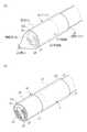
先端部15には、フード16が装着されている。図2に示すように、フード16は、弾性部20と筒部21とからなる。弾性部20はフード16の先端部を構成し、先端に拡縮する開口22をもつ先細りの形状である。弾性部20は、生体適合性があり、無色透明且つ弾性を有する材料、例えばシリコーンゴム、ウレタンゴム等からなる。筒部21は、極めて薄肉に形成されている。筒部21は、先端部15の外径と略同じ内径と、先端部15よりも若干大きい長さを有し、弾性部20と段差なく滑らかな境界で継がれ、弾性部20と一体化している。筒部21は、生体適合性があり、ある程度の硬さを有する材料、例えばフッ素樹脂等からなる。なお、弾性部20と筒部21を同じ材料で形成してもよい。 A
筒部21の後端部には、二本の操作ワイヤ23が180°間隔で取り付けられている。操作ワイヤ23には、ある程度の剛性および可撓性を有する材料、例えば金属細線を複数本撚り合せたものが用いられる。操作ワイヤ23は、途中で内視鏡5の挿入部8のシール穴(図示せず)内に埋設される。埋設前の操作ワイヤ23の露呈部分の長さは、弾性部20の長さと略同じである。なお、シール穴は、操作ワイヤ23の外径よりも若干小さい径を有する弾性材料で形成され、挿入部8内に水分等が入り込まない構造となっている。 Two
操作ワイヤ23は、挿入部8内を挿通されて鉗子口14付近に内蔵された巻取り機構17(図1参照)に接続される。巻取り機構17は、例えば、二本の操作ワイヤ23の端が取り付けられる巻き芯と、操作ワイヤ23を巻き取る方向に巻き芯を付勢するゼンマイバネを有する、いわゆるコードリール機構である。巻取り機構17にはさらに、巻き芯がゼンマイバネの付勢によって回転しないよう、巻き芯の回転を阻止するロック部材が設けられている。このロック部材による巻き芯の回転阻止は、鉗子口14付近に配された巻取りボタン18を操作することで解除される。 The
巻取りボタン18を操作するとロック部材の規制が外れ、ゼンマイバネの付勢により巻き芯が回転し、操作ワイヤ23が巻き芯に巻き取られる。巻き芯が操作ワイヤ23を巻き取る量は、シール穴に埋設される前の操作ワイヤ23の露呈部分の長さ、つまり弾性部20の長さ分である。こうすると、(A)の弾性部20で先端部15の先端面15aを覆っている状態(被覆状態)から、(B)の開口22が拡開しつつ弾性部20が後端側に剥かれ、先端面15aが露呈する状態(露呈状態)となる。(B)の状態から弾性部20を先端側に引っ張ると、ロック部材が作動するまで巻き芯がゼンマイバネの付勢に抗して巻取り方向と逆方向に回転し、操作ワイヤ23が巻取り機構17から引き出されて(A)の状態に戻る。なお、操作ワイヤ23を先端側に押し出す機構を設け、半自動で(B)から(A)の状態に戻るようにしてもよい。 When the winding
図1に戻って、プロセッサ装置6は、光源装置7と電気的に接続され、内視鏡システム2の動作を統括的に制御する。プロセッサ装置6は、ユニバーサルコード12や挿入部8内に挿通された配線ケーブル45(図4参照)を介して内視鏡5に給電を行い、シフト機構32(図4参照)の駆動を制御する。また、プロセッサ装置6は、イメージガイド31(図4参照)で伝達された被観察部位の像を、内蔵のCCD58R、58G、58B(図7参照、以下、まとめてCCD58という)で受像し、これにより得られた撮像信号に各種処理を施して画像を生成する。プロセッサ装置6で生成された画像は、プロセッサ装置6にケーブル接続されたモニタ19に体内画像として表示される。 Returning to FIG. 1, the
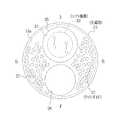
先端部15は、例えば厚み25μm、外径0.8mmのステンレス製パイプを基体とする。フード16を取り外した状態を示す図3において、先端部15の先端面15aには、上方中央に観察窓25が、その直下に鉗子出口26が設けられている。また、観察窓25、鉗子出口26以外の隙間を埋めるように、複数のライトガイド27の先端がランダムに配置されている。 The
鉗子出口26は、例えば外径0.34mm、内径0.3mmであり、ポリイミド等からなる鉗子チャンネル46(図4参照)に連通している。ライトガイド27は、例えば外径50μmの光ファイバからなる。ライトガイド27は、挿入部8、ユニバーサルコード12に亘って挿通され、その入射端が光源用コネクタ11内に位置している。ライトガイド27は、入射端に入射した光源装置7からの照明光を導光して、先端面15aから露呈した先端(出射端)から照明光を被観察部位に照射する。 The
ライトガイド27は、複数本の光ファイバをバラで挿入部8内に挿通させ、その後先端部15に接着剤を流し込むことで先端部15に固着される。必要に応じて、固着後にライトガイド27の出射端を表面研磨したり、各ライトガイド27の出射端前方に、ライトガイド27の出射端が配された部分を覆う照明窓を設けてもよい。さらには、照明窓に蛍光物質を塗り込む等して照明光を拡散させてもよい。 The
図3同様にフード16を取り外した状態の図4に示すように、観察窓25の奥には、対物光学系30、イメージガイド31、およびイメージガイド31をシフトさせるシフト機構32が配されている。対物光学系30は、鏡筒33に保持され、被観察部位の像をイメージガイド31の入射端に結像させる。対物光学系30、鏡筒33の外径はそれぞれ、例えば0.35mm、0.4mmである。また、鏡筒33の軸方向長さは、例えば3.2mmである。 As shown in FIG. 4 with the
イメージガイド31は、例えば外径0.2mmの光ファイバ束からなる(図5参照)。イメージガイド31は、挿入部8、ユニバーサルコード12内を挿通され、その出射端がプロセッサ用コネクタ10内に位置している。イメージガイド31は、対物光学系30に面した入射端から取り込んだ被観察部位の像を出射端に伝達する。 The
図5にも示すように、シフト機構32は、保持筒34、圧電素子35、および電極36で構成される。保持筒34は、例えば外径0.26mm、内径0.2mmのステンレス製パイプからなり、イメージガイド31が内挿固定される。圧電素子35は、例えば厚み15μmであり、保持筒34の外周面を覆う円筒状に成膜されている。電極36は、例えば厚み5μmであり、圧電素子35の外周面に成膜されている。 As shown in FIG. 5, the
シフト機構32は、先端部15の基体内に収容されている。シフト機構32の外周面と先端部15の基体の内周面との間には、例えば0.1mm程度の空洞37が形成されている。 The
シフト機構32は、イメージガイド31の入射端とともに揺動する、先端面15a側の揺動部38と、イメージガイド31とともに固定される、挿入部8側の固定部39とに分れる。揺動部38では、シフト機構32は先端部15の基体に固着されておらず、イメージガイド31は、固定部39を支点として空洞37内を揺動可能である。固定部39では、シフト機構32は接着剤40で先端部15の基体の内周面に固着されている。接着剤40は、イメージガイド31が剥き出しになるシフト機構32の終端手前から、挿入部8の先端途中に掛けて充填されている。揺動部38、固定部39の軸方向長さはそれぞれ、例えば4mm、1.9mmであり、固定部39と挿入部8の先端途中を含む接着剤40の充填範囲の軸方向長さは、例えば3.2mmである。 The
電極36は、周方向に90°間隔(図3の上下左右方向に対して45°傾いた位置)に設けられ、軸方向に平行に形成された四本の溝41によって、上下、左右の二対、計四個に分割されている。揺動部38では、各電極36の間隔が溝41の幅分しか空いておらず、各電極36が幅広となっている。対して、固定部39では溝41が周方向に対称に拡がった形の切欠き42が形成されて、幅狭部43となっている。幅狭部43は、圧電素子35の後端付近まで延在している。溝41および切欠き42は、圧電素子35の外周面全体に電極材料を成膜した後、エッチングによって形成される。 The
幅狭部43の終端にはパッド44が形成され、パッド44には配線ケーブル45が接続されている。パッド44は、保持筒34の終端にも形成されており、これにも配線ケーブル45が接続されている。すなわち、保持筒34は、圧電素子35の共通電極としても機能する。 A
配線ケーブル45は、例えば導線径15μm、被覆外径20μmである。配線ケーブル45は、イメージガイド31の周囲を這うように挿入部8、ユニバーサルコード12内を挿通され、プロセッサ用コネクタ10を介してプロセッサ装置6に接続される。 The
上下、左右で対になった電極36には、共通電極である保持筒34に掛かる電圧を基準として、逆の極性の電圧が供給される。例えば保持筒34の電位が0[V]であった場合、上側の電極36には+5[V]、下側には−5[V]といった具合である。こうすることで電極36下の圧電素子35が軸方向に伸縮し、この圧電素子35の伸縮に連れて、固定部39から先の揺動部38が、イメージガイド31の入射端とともに空洞37内を揺動する。電圧を供給する電極36の組み合わせや印加電圧の値を種々変更することで、揺動部38を所定角度で所定量移動させることができる。 The
図6において、イメージガイド31は、周知の如く、コア50とクラッド51からなる複数本(例えば6000本)の光ファイバ52を、六角最密状に束ねてバンドル化した構成である。本例では、コア50、クラッド51の径はそれぞれ、3μm、6μmであり、光ファイバ52の配列ピッチPは6μmである。 In FIG. 6, the
図7において、プロセッサ装置6は、拡大光学系55および三板式CCD56を有する。拡大光学系55は、プロセッサ用コネクタ10から露呈したイメージガイド31の出射端に面する箇所に配置されている。拡大光学系55は、イメージガイド31で伝達された被観察部位の像を、適当な倍率で拡大して三板式CCD56に入射させる。 In FIG. 7, the
三板式CCD56は、拡大光学系55の背後に配置されている。三板式CCD56は、周知の如く、色分解プリズム57と、三台のCCD58とから構成される。色分解プリズム57は、三個のプリズムブロックと、プリズムブロックの接合面に配された二枚のダイクロイックミラーとからなる。色分解プリズム57は、拡大光学系55からの被観察部位の像を赤、青、緑色の波長帯域を有する光に分け、それぞれの光をCCD58に向けて出射する。CCD58は、色分解プリズム57からの各色光の入射光量に応じた撮像信号を出力する。なお、CCDの代わりにCMOSイメージセンサを用いてもよい。 The three-
イメージガイド31のコア50で伝達する像80を、画素81が配列されたCCD58の撮像面に投影した図8において、像80の中心は、画素81の九個分の枡目の中心と略一致する。イメージガイド31の出射端と色分解プリズム57、CCD58は、像80と画素81が図示する位置関係となるように位置決めされている。 In FIG. 8 in which the image 80 transmitted by the
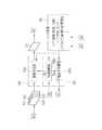
図7に戻って、CCD58からの撮像信号は、アナログフロントエンド(以下、AFEと略す)59に入力される。AFE59は、相関二重サンプリング回路(以下、CDSと略す)、自動ゲイン制御回路(以下、AGCと略す)、およびアナログ/デジタル変換器(以下、A/Dと略す)から構成されている。CDSは、CCD58から出力される撮像信号に対して相関二重サンプリング処理を施し、CCD58で生じるリセット雑音およびアンプ雑音の除去を行う。AGCは、CDSによりノイズ除去が行われた撮像信号を所定のゲイン(増幅率)で増幅する。A/Dは、AGCにより増幅された撮像信号を、所定のビット数のデジタル信号に変換する。A/Dでデジタル化された撮像信号は、デジタル信号処理回路(以下、DSPと略す)65のフレームメモリ(図示せず)に一旦格納される。 Returning to FIG. 7, the imaging signal from the CCD 58 is input to an analog front end (hereinafter abbreviated as AFE) 59. The
CCD駆動回路60は、CCD58の駆動パルス(垂直/水平走査パルス、電子シャッタパルス、読み出しパルス、リセットパルス等)とAFE59用の同期パルスとを発生する。CCD58は、CCD駆動回路60からの駆動パルスに応じて撮像動作を行い、撮像信号を出力する。AFE59の各部は、CCD駆動回路60からの同期パルスに基づいて動作する。なお、図では便宜上、CCD駆動回路60とAFE59はCCD58Gのみに繋がれているが、これらは実際にはCCD58R、58Bにも繋がれている。 The
圧電素子駆動回路61は、配線ケーブル45を介して電極36および保持筒34に繋がれている。圧電素子駆動回路61は、CPU62の制御の下、圧電素子35に電圧を供給する。 The piezoelectric
CPU62は、プロセッサ装置6全体の動作を統括的に制御する。CPU62は、図示しないデータバスやアドレスバス、制御線を介して各部と接続している。ROM63には、プロセッサ装置6の動作を制御するための各種プログラム(OS、アプリケーションプログラム等)やデータ(グラフィックデータ等)が記憶されている。CPU62は、ROM63から必要なプログラムやデータを読み出して、作業用メモリであるRAM64に展開し、読み出したプログラムを逐次処理する。また、CPU62は、検査日時、患者や術者の情報等の文字情報といった検査毎に変わる情報を、後述する操作部68やLAN(Local Area Network)等のネットワークより得て、RAM64に記憶する。 The
DSP65は、AFE59からの撮像信号をフレームメモリから読み出す。DSP65は、読み出した撮像信号に対して、色分離、色補間、ゲイン補正、ホワイトバランス調整、ガンマ補正等の各種信号処理を施し、一フレーム分の画像を生成する。またDSP65は、後述するシフト撮影モードが選択されたときに、シフトの一周期で得られた複数の画像を合成して一つの高解像度な画像(以下、合成画像という)を出力する画像合成部65a(図11参照)を有する。このためDSP65には、複数のフレームメモリが設けられている。DSP65で生成された画像(合成画像も含む)は、デジタル画像処理回路(以下、DIPと略す)66のフレームメモリ(図示せず)に入力される。 The
DIP66は、CPU62の制御に従って各種画像処理を実行する。DIP66は、DSP65で処理された画像をフレームメモリから読み出す。DIP66は、読み出した画像に対して、電子変倍、あるいは色強調、エッジ強調等の各種画像処理を施す。DIP66で各種画像処理を施された画像は、表示制御回路67に入力される。 The
表示制御回路67は、DIP66からの処理済みの画像を格納するVRAMを有する。表示制御回路67は、CPU62からROM63およびRAM64のグラフィックデータを受け取る。グラフィックデータには、体内画像の無効画素領域を隠して有効画素領域のみを表示させる表示用マスク、検査日時、あるいは患者や術者の情報等の文字情報、グラフィカルユーザインターフェース(GUI;Graphical User Interface)といったものがある。表示制御回路67は、DIP66からの画像に対して、表示用マスク、文字情報、GUIの重畳処理、モニタ19の表示画面への描画処理といった各種表示制御処理を施す。 The
表示制御回路67は、VRAMから画像を読み出し、読み出した画像をモニタ19の表示形式に応じたビデオ信号(コンポーネント信号、コンポジット信号等)に変換する。これにより、モニタ19に体内画像が表示される。 The
操作部68は、プロセッサ装置6の筐体に設けられる操作パネル、内視鏡5の操作部9にあるボタン、あるいは、マウスやキーボード等の周知の入力デバイスである。CPU62は、操作部68からの操作信号に応じて、各部を動作させる。 The
プロセッサ装置6には、上記の他にも、画像に所定の圧縮形式(例えばJPEG形式)で画像圧縮を施す圧縮処理回路や、レリーズボタン13の操作に連動して、圧縮された画像をCFカード、光磁気ディスク(MO)、CD−R等のリムーバブルメディアに記録するメディアI/F、LAN等のネットワークとの間で各種データの伝送制御を行うネットワークI/F等が設けられている。これらはデータバス等を介してCPU62と接続されている。 In addition to the above, the
光源装置7は、光源70を有する。光源70は、赤から青までのブロードな波長の光(例えば、480nm以上750nm以下の波長帯の光)を発生するキセノンランプや白色LED(発光ダイオード)等である。光源70は、光源ドライバ71によって駆動される。絞り機構72は、光源70の光射出側に配置され、集光レンズ73に入射される光量を増減させる。集光レンズ73は、絞り機構72を通過した光を集光して、ライトガイド27の入射端に導光する。CPU74は、プロセッサ装置6のCPU62と通信し、光源ドライバ71および絞り機構72の動作制御を行う。 The
内視鏡システム2には、シフト機構32を動作させないで撮影する通常撮影モードと、シフト機構32を使用するシフト撮影モードとが用意されている。シフト撮影モードでは、シフト回数を四回、九回の二種類設定することが可能である。各モードの切り替えおよびシフト回数の設定は、操作部68を操作することにより行われる。 The
シフト撮影モードが選択されてシフト回数が四回に設定(以下、単に四回シフトという)された場合、圧電素子駆動回路61は、シフト機構32の揺動部38を駆動して、イメージガイド31の入射端を図9に示すようにシフト動作させる。まず、揺動部38は、(a)の初期位置から30°左斜め下方向に、光ファイバ52の配列ピッチPの半分、つまり1/2P分イメージガイド31の入射端を揺動させ、(b)に示す一回シフトの位置に移動させる。そして、順次右斜め下方向、右斜め上方向、左斜め上方向に、最初と同じ角度、同じ移動量でシフトさせて、(c)の二回シフト、(d)の三回シフトの位置に移動させ、再び(a)の初期位置(四回シフトの位置)に戻す。揺動部38は、圧電素子駆動回路61によって、各シフト位置でその都度止められる。なお、実線はイメージガイド31の入射端における実際のコア50の位置、破線は一つ前の位置を表す。 When the shift photographing mode is selected and the number of shifts is set to four (hereinafter, simply referred to as four shifts), the piezoelectric
イメージガイド31の入射端におけるコア50は、(a)〜(d)、そして再び(a)に戻る一周期のシフト動作を繰り返すことで、(a)の初期位置だけでは画像化されないクラッド51の部分を埋めるような、図10(a)に示す菱形状の移動軌跡を辿る。 The core 50 at the incident end of the
因みにシフト回数が九回に設定(以下、単に九回シフトという)された場合の移動軌跡は、例えば図10(b)に示す如くである。四回シフトの場合と比べて、各方向へのシフト動作が一回多くなる。但し、七回シフトから八回シフトの位置に移るときは、六回シフトから七回シフトの位置に移ったときの左斜め上方向から、左斜め下方向に方向が変えられる。また、八回シフトから初期位置(九回シフトの位置)に移るときは、角度が90°に変えられて上方向に移動される。九回シフトの場合も四回シフトの場合と同様に、初期位置だけでは画像化されないクラッド51の部分を埋めるような移動軌跡となる。そのうえ、隣接する三つのコア50の初期位置と同じ位置(二回、四回、六回シフトの位置)に移動される。 Incidentally, the movement trajectory when the number of shifts is set to nine times (hereinafter simply referred to as nine shifts) is as shown in FIG. 10B, for example. The shift operation in each direction is increased once compared to the case of four shifts. However, when shifting from the 7th shift to the 8th shift position, the direction is changed from the diagonally upper left direction when moving from the 6th shift to the 7th shift position to the diagonally lower left direction. Further, when moving from the eighth shift to the initial position (position of nine shifts), the angle is changed to 90 ° and moved upward. In the case of the nine-time shift, similarly to the case of the four-time shift, the movement locus fills the portion of the
図11において、シフト撮影モードが選択されると、プロセッサ装置6のCPU62には、同期制御部62a、圧電素子制御部62bが構築され、また、DSP65の画像合成部65aが動作する。画像合成部65aおよび各制御部62a、62bは、シフト情報85に基づいて互いに協働しながら各種処理を行う。 In FIG. 11, when the shift shooting mode is selected, a
シフト情報85は、シフト機構32の揺動部38のシフト動作に関する情報である。シフト情報85は、シフト回数、シフト方向とそのピッチ、図8に示すイメージガイド31のコア50で伝達する像80とCCD58の画素81の位置関係等を含む。シフト回数の情報は操作部68から与えられる。シフト方向、ピッチ、像80と画素81の位置関係といった基本的な情報は例えばROM63に記憶されており、ROM63から画像合成部65aおよび各制御部62a、62bに読み出される。 The
同期制御部62aは、CCD駆動回路60からCCD58の駆動パルスの情報を受けて、圧電素子制御部62bに圧電素子制御信号Saを、画像合成部65aに画像合成信号Sbをそれぞれ送信する。圧電素子制御部62bは、圧電素子制御信号Saに同期してシフト動作が行われるよう、圧電素子駆動回路61の動作を制御する。同様に、画像合成部65aは、画像合成信号Sbに同期して画像合成処理を実行し、各回のシフト位置で得られた画像G0、G1、G2、G3(四回シフトの場合を例示)の画素を、各シフト位置に対応させてマッピングすることにより、一つの合成画像Gcを生成する。 The
より詳しくは、四回シフトの場合を例示した図12において、同期制御部62aは、CCD58の電荷蓄積が終了した直後、すなわちCCD58の画素81から垂直転送路に一フレーム分の信号電荷が読み出されたとき(CCD駆動回路60からCCD58に読み出しパルスが出力されたとき)に、圧電素子制御信号Saを発する。また、同期制御部62aは、三回シフトの位置で得られた画像G3に該当するCCD58の電荷読出出力が終了したときに、画像合成信号Sbを発する。電荷読出出力とは、読み出しパルスに応じてCCD58の画素81から垂直転送路に信号電荷が読み出され、垂直転送、水平転送を経て、一フレーム分の撮像信号が出力されるまでの一連のCCD動作をいう。 More specifically, in FIG. 12 illustrating the case of the four-time shift, the
圧電素子駆動回路61は、圧電素子制御信号Saを受けて圧電素子35に相応の電圧を供給し、揺動部38を前回のシフト位置から次回のシフト位置に移動させる。同期制御部62aから圧電素子駆動回路61に圧電素子制御信号Saが発せられてから、揺動部38が次回のシフト位置に移動するまでの時間は、CCD58が前回の電荷蓄積を終えてから次回の電荷蓄積を開始するまでの時間よりも短い。従って、揺動部38が圧電素子駆動回路61により次回のシフト位置に移動されて制止された状態で、常に次回の電荷蓄積が開始される。 The piezoelectric
画像合成部65aは、画像合成信号Sbを受けて、各回のシフト位置で得られた画像G0〜G3をフレームメモリから読み出す。画像合成部65aは、各画像G0〜G3の画素を、各シフト位置に対応させてマッピングし、合成画像Gcを出力する。合成時に各画像G0〜G3や合成画像Gcに対して画素補間を施してもよい。 The
合成画像Gcは、画像化されないクラッド51の部分が画像化され、しかもその部分の画素値が一フレーム内の隣接画素の補間で得た擬似値ではなく、被観察部位の像を反映したものとなる。言い換えれば、通常撮影モードや各回のシフト位置で得られた画像よりも画素数が増え、よりきめ細かい画像となる。この画像の鮮明さは、四回シフトよりもサンプリング数が多い九回シフトのほうが当然より顕著になる。 In the composite image Gc, a portion of the
なお、ここで注意すべきは、各画像G0〜G3の実態は、シフト動作で各シフト位置にずらされたそれぞれ異なる像80であるが、イメージガイド31の出射端を固定して入射端における像80のみをシフトさせており、CCD58の撮像面とイメージガイド31の出射端の相対的な位置関係は変わらないので、データ上は各シフト位置とも同じ画素81から出力されていて区別がつかないという点である。例えば、画像G0内のある位置の像80と画像G1内の同じ位置の像80とは、それぞれシフト位置が異なる像80であるが、CCD58の同じ画素81で撮像される。他の画像も同様である。このため、画像合成部65aは、シフト情報85の像80と画素81の位置関係を元に、各画像の画素値が本来どの画素81に該当するかをマッピングで割り出し、上記の画素補間等を行う。 It should be noted that the actual state of each of the images G0 to G3 is a different image 80 shifted to each shift position by the shift operation, but the image at the incident end with the output end of the
次に、上記のように構成された内視鏡システム2の作用について説明する。内視鏡5で患者の体内を観察する際、術者は、内視鏡5と各装置6、7とを繋げ、各装置6、7の電源をオンする。そして、操作部68を操作して、患者に関する情報等を入力し、検査開始を指示する。 Next, the operation of the
検査開始を指示した後、術者は、挿入部8を体内に挿入し、光源装置7からの照明光で体内を照明しながら、CCD58による体内画像をモニタ19で観察する。 After instructing the start of the examination, the surgeon inserts the
挿入部8を体内に挿入する際、フード16は、図2(A)に示す先端面15aを弾性部20で覆った状態とされる。弾性部20で保護されているため、先端面15aには人体管路内の異物は付着しない。また、弾性部20が無色透明な材料からなるため、観察が妨げられることはない。一方、先端部15が目的とする被観察部位に到達し、被観察部位の観察を開始する際、術者は、巻取りボタン18を操作して巻取り機構17を作動させ、フード16を図2(B)に示す後端側に弾性部20を剥いた状態とする。先端面15aが露呈され、図2(A)に示す弾性部20が被っている状態よりもクリアな視野が確保される。 When the
CCD58から出力された撮像信号は、AFE59の各部で各種処理を施された後、DSP65に入力される。DSP65では、入力された撮像信号に対して各種信号処理が施されて画像が生成される。DSP65で生成された画像は、DIP66に出力される。 The imaging signal output from the CCD 58 is input to the
DIP66では、CPU62の制御の下、DSP65からの画像に各種画像処理が施される。DIP66で処理された画像は、表示制御回路67に入力される。表示制御回路67では、CPU62からのグラフィックデータに応じて、各種表示制御処理が実行される。これにより、画像がモニタ19に体内画像として表示される。 In the
図13において、シフト撮影モードが選択された場合(S10でyes)、プロセッサ装置6のCPU62に同期制御部62a、圧電素子制御部62bが構築される。そして、シフト情報85、およびCCD駆動回路60からのCCD58の駆動パルスの情報に基づいて、同期制御部62aから圧電素子制御部62bに圧電素子制御信号Saが、画像合成部65aに画像合成信号Sbがそれぞれ送信される。 In FIG. 13, when the shift photographing mode is selected (Yes in S10), a
圧電素子制御信号Saを受けた圧電素子制御部62bによって、圧電素子駆動回路61の動作が制御され、圧電素子駆動回路61から圧電素子35に相応の電圧が供給される。これにより、設定されたシフト回数に応じて、揺動部38が所定角度、所定ピッチ分順次シフトされる(S11)。そして、揺動部38が各シフト位置に止まっているときに、CCD58による電荷蓄積が行われ、イメージガイド31で伝達された被観察部位の像80が各画素81で撮像される(S12)。揺動部38が初期位置からシフトされて再び初期位置に戻り、一周期のシフト動作が終了するまで、S11、S12の処理が繰り返される(S13でno)。 The operation of the piezoelectric
一周期のシフト動作が終了すると(S13でyes)、画像合成信号Sbを受けた画像合成部65aによって画像合成処理が実行され、各回のシフト位置で得られた画像から、一つの合成画像が生成される(S14)。生成された合成画像は、前述のようにDIP66、表示制御回路67を経由して、モニタ19に表示される(S15)。一方、通常撮影モードが選択された場合は、S12の撮影は行われるが、S11、S14の処理は実行されない。これら一連の処理は、検査終了が指示される(S16でyes)まで繰り返される。 When the shift operation for one cycle is completed (yes in S13), the image composition processing is executed by the
以上説明したように、挿入部8の挿入時には先端面15aを覆って保護し、目的とする被観察部位の観察時には先端面15aを露呈させるフード16を設けたので、挿入部8の挿入時に異物が先端部15に付着することがなく、且つ観察時にはよりクリアな視野を確保することができる。 As described above, the
筒部21を操作部9の根元付近まで延設して袋状としてもよい。この場合、操作ワイヤ23は挿入部8に埋設する必要はなく、筒部21に穿たれたチャンネル(図14のチャンネル95参照)内に挿通する。挿入部8に操作ワイヤ23を埋設するためのシール穴を設けなくともよくなる。また、挿入部8を筒部21で保護することもできる。 The
なお、変形例として、図14に示すフード90を用いてもよい。フード90は、弾性部20の代わりに蓋部91を有する。蓋部91は、弾性部20と同様に無色透明な材料からなる。蓋部91は筒部92にヒンジ93を介して取り付けられており、ヒンジ93を軸にして矢印方向に開閉可能である。ヒンジ93はコイルバネ(図示せず)を内蔵し、蓋部91を開く方向に付勢している。図では蓋部91がコイルバネの付勢に抗して閉じられた状態を示している。 As a modification, a hood 90 shown in FIG. 14 may be used. The hood 90 has a lid portion 91 instead of the
ヒンジ93と反対側の蓋部91の裏面91a(図15参照)には、一本の操作ワイヤ94が取り付けられている。操作ワイヤ94は、操作ワイヤ23と同様、金属細線の撚り線からなる。操作ワイヤ94は、筒部92に穿たれたチャンネル95内を挿通されて筒部92の後端部から外部に露呈し、挿入部8のシール穴に埋設される。操作ワイヤ94は、挿入部8を挿通されて、その端が鉗子口14付近の巻取り機構(図示せず)の巻き芯に取り付けられる。 A single operation wire 94 is attached to the
この場合、巻取り機構は、上記実施形態の巻取り機構17の機能に加えて、ゼンマイバネの付勢を解除して巻き芯をフリー回転させる機能および操作ボタンを有する。また、ゼンマイバネの付勢力は、ヒンジ93のコイルバネのそれよりも大きい。巻取りボタン18の操作によりロック部材の規制が外れているときには、巻き芯の回転によって操作ワイヤ94が後端側に引っ張られ、蓋部91はコイルバネの付勢に抗して閉じる。 In this case, in addition to the function of the winding mechanism 17 of the above-described embodiment, the winding mechanism has a function and an operation button for releasing the bias of the mainspring spring to freely rotate the winding core. Further, the urging force of the spring spring is larger than that of the coil spring of the
巻き芯をフリー回転させるための操作ボタンが操作されると、操作ワイヤ94への引っ張り力が失われ、蓋部91がコイルバネの付勢によって開く。蓋部91が開いているとき、または閉じているときにロック部材を作動させると、その途中で蓋部91が停止する。蓋部91の最大開き角は例えば90°(もちろん90°以上でも可)であり、そうなるように操作ワイヤ94の長さ、および巻き芯が操作ワイヤ94を巻き取る量が調節されている。 When the operation button for freely rotating the winding core is operated, the pulling force on the operation wire 94 is lost, and the lid 91 is opened by the bias of the coil spring. When the lock member is operated when the lid portion 91 is open or closed, the lid portion 91 stops midway. The maximum opening angle of the lid portion 91 is, for example, 90 ° (of course, 90 ° or more is possible), and the length of the operation wire 94 and the winding amount of the operation wire 94 by the winding core are adjusted so as to be so.
挿入部8を体内に挿入する際、術者は、巻取りボタン18を操作して蓋部91を閉じさせ、先端面15aを蓋部91で覆った図示の状態とする。一方、目的とする被観察部位の観察を開始する際、術者は、巻き芯をフリー回転させるための操作ボタンを操作して蓋部91を開かせ、先端面15aを露呈させる。この場合も上記実施形態と同様の効果を得ることができる。 When inserting the
なお、筒部92を除き、蓋部91を先端部15に直接取り付けてもよい。また、ヒンジ93を鉗子出口26側に、操作ワイヤ94が蓋部91の裏面91aに取り付けられる箇所を観察窓25側にしてもよい。さらに、蓋部91を開いたときに、操作ワイヤ94が観察の邪魔にならないよう、操作ワイヤ94が蓋部91の裏面91aに取り付けられる箇所を例えばヒンジ93の近く等に変更してもよい。 Note that the lid portion 91 may be directly attached to the
図15に示すように、蓋部91の裏面91aの観察窓と対面する箇所(二点鎖線で囲む部分)100の一部、例えば中央に、シフト量の校正チャート101を取り付けてもよい。この場合、イメージガイド31のシフト方向が、後述する校正チャート101の黒白各領域110a、110bの幅方向と平行になるように、フード90が先端部15に位置決め固定される。この位置決めの手段としては、フード90の筒部92の内面に溝または突起、先端部15の周面に筒部92の溝に嵌合される突起または筒部92の突起が嵌合する溝を設けてもよいし、先端部15を雄ネジ、筒部92を雌ネジとして螺合させてもよい。 As illustrated in FIG. 15, a shift amount calibration chart 101 may be attached to a part, for example, the center, of a portion (portion surrounded by a two-dot chain line) that faces the observation window on the
イメージガイド31やこれをシフト動作させる圧電素子35には個体差があるため、規格通りに圧電素子35を駆動させても、イメージガイド31の入射端が規定のシフト量でシフトしない場合がある。規定のシフト量でないと、合成画像Gcを生成する際にズレが生じ、合成画像Gcにアーチファクトを発生させる原因となる。これを防止するため、校正チャート101を用いてシフト量の校正を行う。 Since there are individual differences between the
図16に示すように、校正チャート101は、同じ幅dhをもつ黒領域(ハッチング部分)110aと白領域(ハッチングなし)110bが交互に且つ平行に並べられた黒白縞状である。黒白各領域110a、110bを合せた幅2dhは、正味のシフト量Hs(30°の方向のシフト量、図10参照)の定数倍(2dh=khHs、khは定数)である。定数khは、対物光学系30の倍率と、蓋部91を閉じたときの先端面15aと蓋部91の裏面91aとの距離に応じて決められる。定数khは、蓋部91を閉じて先端面15aと蓋部91の裏面91aを対面させたときに、CCD58に映る黒白各領域110a、110bを合せた幅2dhが、正味のシフト量Hsと一致する値である。 As shown in FIG. 16, the calibration chart 101 has a black and white stripe shape in which black regions (hatched portions) 110a and white regions (not hatched) 110b having the same width dh are arranged alternately and in parallel. The total width 2dh of the black and
図17において、シフト量の校正を行う場合、圧電素子駆動回路61は、CPU62の制御の下、デフォルトの駆動電圧Vと、そのm/nの駆動電圧(例えば1/4V、1/2V、3/4V等)で連続的に圧電素子35を駆動させ、その都度シフト前の状態(点線で示す0の状態)に戻す。デフォルトの駆動電圧Vは、イメージガイド31の入射端を規定のシフト量でシフトさせるべく圧電素子35を駆動させたときの駆動電圧である。圧電素子35が規定通り駆動すれば、デフォルトの駆動電圧Vを印加すると、イメージガイド31の入射端が正味のシフト量Hsで30°の方向にシフトする。駆動電圧m/nVでは、シフト量m/nHsでシフトする。圧電素子35が規定通り駆動しない場合、シフト量はm/nHsからずれる。 In FIG. 17, when the shift amount is calibrated, the piezoelectric
イメージガイド31の入射端は、シフト量を段階的に増しながら、点線の位置を基点として、該基点と実線で示す各シフト量離れた位置の間で往復振動する。前回のシフト位置から基点位置まで戻り、次回のシフト位置までシフトする時間は、上述のシフト撮影モードで前回のシフト位置から次回のシフト位置までシフトする時間と同じである。つまり、シフト撮影モードのときと同じ駆動周波数でイメージガイド31の入射端をシフトさせる。 The incident end of the
カメラのマークで擬似的に示すように、CCD58は、最初に基点位置で一回、各シフト位置でその都度校正チャート101を撮像する。CPU62は、CCD58で校正チャート101を撮像して得られた校正用画像の一部または全領域の黒濃度を検出し、これを元にシフト量(圧電素子35の駆動電圧)の校正を行う。このときの照明光は、使用時と同様に光源装置7の光源70からの光を用いる。 As indicated by the camera mark, the CCD 58 first images the calibration chart 101 once at the base position and at each shift position. The
先端部15とフード90の上記位置決めによって、イメージガイド31のシフト方向が校正チャート101の黒白各領域110a、110bの幅方向と平行になるようにされている。この場合は、図18に示すように、シフト量に応じて黒濃度が変動する。黒濃度は、一本のコア50で伝達する像80の中央に黒領域110aがあるとき最大値となり、逆に白領域110bがあるとき最小値となる。そして、像80に黒白各領域110a、110bが半々に映ったときに中間値をとる。この黒濃度の変動の周期は、2dh=khHsであるから、正味のシフト量Hsと同じである。コア50毎に得られる像80の全て、つまり校正用画像の全てが同じ変動をするとは限らないが、部分的に多少のずれはあれど、概ねこのような変動となる。 By the positioning of the
圧電素子35が規定通り駆動した場合、各シフト位置での像80と、基点位置と各シフト位置の像80の合成像は、図19に示すようになる。ここでは、基点位置で像80に黒白各領域110a、110bが半々に映っていた場合を例示している。圧電素子35を駆動電圧1/4Vで駆動させ、イメージガイド31の入射端をシフト量1/4Hsでシフトさせた場合、像80の中央には白領域110bが映り、合成像は右側中央寄りの一部を除いて黒領域110aが占める。駆動電圧1/2V、シフト量1/2Hsの場合の像80は、基点位置の像80と対称に黒白各領域110a、110bが半々に映り、合成像には全て黒領域110aが映る。シフト量3/4Hsの場合の像80は、1/4Hsの場合の像80と逆に中央に黒領域110aが映る。合成像は右側端寄りの一部を除いて黒領域110aとなる。シフト量Hsの場合は、基点位置の像80と同じ映り方に戻り、合成像も同じになる。シフト量がHsの2倍、3倍、・・・(2Hsを例示)となっても、シフト後の像80と合成像はシフト量Hsの場合と同じである。 When the
合成像の黒濃度は、全黒になるシフト量1/2Hsのときに最大値となり、基点位置とシフト量Hs(2Hs、3Hs、・・・)のときに最小値となり一致する。つまり合成像の黒濃度もシフト量に応じて周期的に変動し、その変動周期はHsとなる。基点位置の像80がここで例示する黒白半々のものでなくても、位相がずれるだけで基点位置とシフト量Hsでの合成像の黒濃度は必ず一致する。 The black density of the composite image has a maximum value when the shift amount is ½ Hs to be all black, and is a minimum value and coincides with the base point position and the shift amount Hs (2Hs, 3Hs,...). That is, the black density of the composite image also periodically varies according to the shift amount, and the variation period is Hs. Even if the image 80 at the base point position is not one of the black and white illustrated here, the black density of the composite image at the base point position and the shift amount Hs is always the same only by the phase shift.
CPU62は、基点位置での校正用画像と、各シフト位置での校正用画像の合成画像(合成画像Gcとは異なる)の黒濃度を検出する。デフォルトの駆動電圧Vで圧電素子35を駆動したときに、基点位置の校正用画像と合成画像の黒濃度が一致するのであれば、イメージガイド31の入射端が規定通りシフト量Hsでシフトしたことになり、圧電素子35の駆動電圧の調整は不要である。 The
一方、基点位置の校正用画像と合成画像の黒濃度が一致しなかった場合は、デフォルトの駆動電圧Vで圧電素子35を駆動させても、規定のシフト量Hsでイメージガイド31の入射端がシフトされていないので、CPU62は、シフト量が校正されるように圧電素子35の駆動電圧を決定する。例えば、デフォルトの駆動電圧Vの前後で1/10V刻みで駆動電圧を変えながら、イメージガイド31の入射端を基点との間で往復振動させて(例えば基点から8/10Vで駆動させて基点に戻した後、9/10Vで駆動させて基点に戻すといった動作を繰り返させる)、校正チャート101をCCD58で撮像し、基点位置の校正用画像と合成画像の黒濃度が一致したときの駆動電圧を圧電素子35の駆動条件とする。 On the other hand, if the black density of the calibration image at the base point and the synthesized image do not match, even if the
デフォルトの駆動電圧Vで圧電素子35を駆動させたときに、基点位置の校正用画像と合成画像の黒濃度が一致しなかった場合、CPU62は、駆動電圧をVの前後で振って黒濃度が一致した駆動電圧を、内視鏡5のROM47(図7参照、EEPROM等の書き込み可能なROM)に記憶させる。ROM47には当初、デフォルトの駆動電圧Vが駆動条件として書き込まれており、校正で駆動電圧がV以外となった場合にCPU62によって書き換えられる。この駆動電圧は、使用する際にROM47からプロセッサ装置6のCPU62に読み出され、圧電素子駆動回路61に与えられる。 When the
蓋部91の裏面91aに校正チャート101を取り付けてシフト量の校正を可能とすれば、内視鏡検査の途中でイメージガイド31のシフト量の校正をすることができ、合成画像Gcのアーチファクトの発生を防止することができる。 If the calibration chart 101 is attached to the
なお、校正チャートに加えて、あるいは代えて、蓋部の裏面に調光ミラーを設けてもよい。調光ミラーは、蓋部が閉じているときは透明で、開いているときは反射ミラーとなる。そして、観察窓25の視野では取り込めない部位の像を観察窓25へと導く。こうすれば、蓋部が閉じているときは視野を確保し、蓋部が開いているときは視野を広げることができる。 In addition to or instead of the calibration chart, a light control mirror may be provided on the back surface of the lid. The light control mirror is transparent when the lid is closed, and is a reflection mirror when the cover is open. Then, an image of a part that cannot be captured in the visual field of the
体内の湿気による曇りを防止するため、弾性部20や蓋部91に親水性表面処理を施してもよい。親水性表面処理としては、例えば親水性ポリマー微粒子を添加した合成樹脂塗料を塗布したり、酸化チタン光触媒膜を成膜したりすることが挙げられる。 In order to prevent fogging due to moisture in the body, the
フードは洗浄して繰り返し使用しても使い捨てでも構わない。使い捨ての場合は、操作ワイヤに着脱機構を設け、使用の都度フードを交換する。 The hood can be washed and used repeatedly or can be disposable. In the case of a single use, an attaching / detaching mechanism is provided on the operation wire, and the hood is replaced every time it is used.
上記実施形態では、操作機構の例として巻取り機構17を挙げたが、操作ワイヤの端に指掛けリングをつけて術者に引っ張らせてもよく、あるいは一般的な内視鏡の湾曲部を湾曲動作させるためのアングルノブのように、操作ワイヤを牽引または押し出す機構でもよい。また、操作ワイヤではなく、MEMSモータといった微小アクチュエータを用いて、被覆状態から露呈状態にしてもよい。 In the above-described embodiment, the winding mechanism 17 has been described as an example of the operation mechanism. However, a finger hook ring may be attached to the end of the operation wire and pulled by the operator, or a curved portion of a general endoscope is curved. A mechanism that pulls or pushes the operation wire may be used, such as an angle knob for operation. Further, instead of the operation wire, a micro actuator such as a MEMS motor may be used to change from the covered state to the exposed state.
上記実施形態では、先端面15aを覆う弾性部20、蓋部91を無色透明な材料から形成しているが、本発明はこれに限らない。弾性部20、蓋部91を着色材料から形成してもよい。この場合、挿入時は体内画像を観察することができなくなるが、X線画像撮影装置等の他の体内画像撮影装置で内視鏡の挿入をガイドすれば問題はない。 In the said embodiment, although the
シフト機構の構成は、円柱状に限らない。例えば四角柱状でもよい。この場合はイメージガイドを四角筒状の保持筒に内挿固定し、保持筒の四辺にそれぞれ電極を形成する。そして、上下左右に保持筒毎イメージガイドをシフト動作させる。例えば、初期位置から90°左方向に√3/4P分シフトさせ、一回シフトの位置に移動させる。そして、初期位置に戻してから90°下方向に1/4P分シフトさせ、二回シフトの位置に移動させる。二回シフトの位置から再度初期位置に戻した後、順次右方向、上方向にシフトさせ、再び初期位置に戻す。こうすることで、コア50は十字状の移動軌跡を辿る。なお、この場合は校正チャートを上下、左右方向の二種類用意し、校正チャート101と同様に、黒白各領域の幅を初期位置から上下、左右へのシフト量の定数倍とすればよい。 The configuration of the shift mechanism is not limited to a cylindrical shape. For example, a quadrangular prism shape may be used. In this case, the image guide is inserted and fixed in a rectangular cylindrical holding cylinder, and electrodes are respectively formed on the four sides of the holding cylinder. Then, the image guide for each holding cylinder is shifted up, down, left and right. For example, it is shifted by √3 / 4P to the left by 90 ° from the initial position, and moved to the position of one shift. Then, after returning to the initial position, it is shifted by 90 ° downward by ¼ P, and moved to the position of the double shift. After returning from the double shift position to the initial position again, it is sequentially shifted rightward and upward, and then returned to the initial position again. By doing so, the
圧電素子にはヒステリシス特性があり、無秩序に駆動させるとシフト位置がずれるため、移動軌跡は毎回同じとし、常に同じ移動経路でシフト機構をシフトさせる。つまり、シフト機構をシフトさせる際の圧電素子の駆動順序を毎回同じにする。また、上下、左右で対になった電極に電圧を供給する順序も同じにする。シフト量の校正をする場合も同様である。 The piezoelectric element has a hysteresis characteristic, and the shift position shifts when driven in a chaotic manner. Therefore, the movement locus is the same every time, and the shift mechanism is always shifted along the same movement path. That is, the driving order of the piezoelectric elements when shifting the shift mechanism is made the same every time. In addition, the order in which the voltage is supplied to the paired electrodes on the top and bottom and the left and right is also made the same. The same applies when the shift amount is calibrated.
イメージガイドは揺動部が根元から撓ることでシフトをするので、各シフト位置にすぐには停止せず、しばらく振動してから止まる可能性がある。このため、シフト機構の停止後、シフト方向とは逆方向に瞬間的に揺動部が振れるように、圧電素子駆動回路で圧電素子を駆動する等の制振対策を講じることが好ましい。具体的には、反力をシミュレーションや実測で求めて、これを打ち消すための圧電素子の駆動電圧をROMに記憶させておき、圧電素子制御部がその駆動電圧の情報をROMから読み出して圧電素子駆動回路に与える。あるいは、空洞に絶縁性の粘性流体を封入してダンピング効果を利用し、制振対策を講じてもよい。 Since the image guide shifts when the swinging portion is bent from the base, there is a possibility that the image guide does not stop immediately at each shift position but stops after vibrating for a while. For this reason, after stopping the shift mechanism, it is preferable to take a vibration suppression measure such as driving the piezoelectric element with a piezoelectric element drive circuit so that the swinging part instantaneously swings in the direction opposite to the shift direction. Specifically, the reaction force is obtained by simulation or actual measurement, and the drive voltage of the piezoelectric element for canceling the reaction force is stored in the ROM, and the piezoelectric element control unit reads the drive voltage information from the ROM and outputs the piezoelectric element. Give to the drive circuit. Alternatively, an insulating viscous fluid may be sealed in the cavity and a damping effect may be used to take a vibration suppression measure.
なお、揺動部が次回のシフト位置に移動するまでの時間が、CCDが前回の電荷蓄積を終えてから次回の電荷蓄積を開始するまでの時間よりも短いと説明しているが、揺動部の長さ、材質、あるいはシフト量、さらには圧電素子自体の性能等が要因で、前者の時間が後者の時間よりも長くなることもあり得る。前述のようにイメージガイドの慣性質量が比較的重いことから、前者の時間が後者の時間よりも長くなる可能性が高い。 It is described that the time until the rocking unit moves to the next shift position is shorter than the time from when the CCD finishes the previous charge accumulation until the next charge accumulation starts. The former time may be longer than the latter time due to factors such as the length of the part, the material, the shift amount, and the performance of the piezoelectric element itself. As described above, since the inertial mass of the image guide is relatively heavy, the former time is likely to be longer than the latter time.
こうした場合には、揺動部がシフト位置に移動している間は、プロセッサ装置のCPUの制御の下、CCD駆動回路からCCDに電子シャッタパルスを供給して電荷蓄積を開始する時間を遅らせ、揺動部がシフト位置に停止してから電荷蓄積を開始する。あるいは、揺動部がシフト位置に移動している間は光源を消灯し、揺動部がシフト位置に停止したら光源を点灯する。 In such a case, while the oscillating unit is moved to the shift position, under the control of the CPU of the processor device, the electronic shutter pulse is supplied from the CCD driving circuit to the CCD to delay the time for starting the charge accumulation, Charge accumulation starts after the rocking portion stops at the shift position. Alternatively, the light source is turned off while the swinging portion is moved to the shift position, and the light source is turned on when the swinging portion is stopped at the shift position.
揺動部が次回のシフト位置に移動するまでの時間を基準にしてCCDを駆動しようとすると、前者の時間が後者の時間よりも長くなる場合はフレームレートを落とさなければならないが、電子シャッタパルスで電荷を掃き出すか、光源を点消灯させる上記いずれかの方法を採用すれば、フレームレートは現行を維持しつつブレのない画像を得ることができる。 If it is attempted to drive the CCD based on the time until the swing unit moves to the next shift position, if the former time is longer than the latter time, the frame rate must be reduced. If any one of the above-described methods of sweeping out the electric charge or turning off the light source is employed, a blur-free image can be obtained while maintaining the current frame rate.
なお、シフト撮影モードが選択されたときのみ画像合成部で画像合成処理をしているが、通常撮影モード時にも画像合成処理をしてもよい。クラッドの位置に対応する被観察部位の像を反映した画像は得られないが、クラッドの影は埋めることができる。 Note that the image composition processing is performed by the image composition unit only when the shift photographing mode is selected, but the image composition processing may also be performed during the normal photographing mode. Although an image reflecting the image of the observed region corresponding to the position of the clad cannot be obtained, the shadow of the clad can be filled.
また、シフトの一周期毎に画像合成部で画像合成処理を行い、一つの合成画像を出力しているが、この方法であると通常撮影モードに比べてフレームレートが落ちる。このフレームレート低下の対策としては、四回シフトの場合は通常撮影モードの四倍といったように、シフト撮影モードが選択されたときにフレームレートを上げることが考えられる。 In addition, the image composition process is performed by the image composition unit for each shift period and one composite image is output. However, this method has a lower frame rate than the normal shooting mode. As a countermeasure for this frame rate decrease, it is conceivable to increase the frame rate when the shift shooting mode is selected, such as four times the normal shooting mode in the case of four shifts.
具体的には、CPU62のシステムクロックのクロック信号の周期を変化させることで、CCD駆動回路60の駆動信号の周期を変化させる。あるいは、システムクロックのクロック信号は変化させずに、CCD駆動回路60に分周器を設け、この分周器でシステムクロックのクロック信号を分周することで変化させてもよい。 Specifically, the cycle of the drive signal of the
あるいは、例えば四回シフトの場合に、同じシフト周期の画像G0〜G3で合成画像Gcを生成した後、その画像G1〜G3と次のシフト周期の画像G0から合成画像Gcを生成するというように、画像の組み合わせを一画像ずつずらして、G0〜G3の画像のうちの一番古い画像を新しく得られた画像に順次置き換えながら合成画像Gcを生成してもよい。こうすれば、クロック信号の周期を変化させたりする制御の面倒が省け、しかもフレームレートの低下を防ぐことができる。 Or, for example, in the case of four-time shift, after generating the composite image Gc with the images G0 to G3 having the same shift cycle, the composite image Gc is generated from the images G1 to G3 and the image G0 having the next shift cycle. Alternatively, the combined image Gc may be generated by shifting the combination of the images one by one and sequentially replacing the oldest image among the G0 to G3 images with a newly obtained image. In this way, it is possible to omit the troublesome control of changing the cycle of the clock signal, and to prevent the frame rate from being lowered.
三板式CCD、モード切り替えとシフト回数の設定をする操作部、および画像合成部と同期制御部と圧電素子制御部の機能を実現するハードウェアを、プロセッサ装置とは別の筐体に搭載してもよいし、内視鏡に搭載してもよい。 A three-panel CCD, an operation unit that switches modes and sets the number of shifts, and hardware that implements the functions of the image composition unit, synchronization control unit, and piezoelectric element control unit are mounted in a separate housing from the processor unit. Alternatively, it may be mounted on an endoscope.
また、照明用の光源として中心波長445nmの青色レーザ光源を用い、青色レーザ光源からのレーザ光の一部を吸収して、緑色〜黄色に励起発光する複数種の蛍光体を有する波長変換部材をライトガイド27の光出射側に配置して、レーザ光と励起光を合成した高輝度な白色光を照明光として照射してもよい。上記実施形態と比べて高輝度な白色光を供給するので、僅かな本数(一、二本)のライトガイドで十分な照明光を得ることができる。従って、極細径化をさらに促進することができる。 Further, a wavelength conversion member having a plurality of types of phosphors that emit green to yellow light by absorbing a part of the laser light from the blue laser light source using a blue laser light source having a central wavelength of 445 nm as a light source for illumination. It may be arranged on the light emitting side of the
なお、イメージセンサとしては、単板式を用いてもよい。また、上記実施形態では、イメージガイドと配線ケーブルのプロセッサ装置への接続を同じコネクタで果たしているが、イメージガイドと配線ケーブルを別のコネクタに実装してもよい。 Note that a single plate type may be used as the image sensor. In the above embodiment, the image guide and the wiring cable are connected to the processor device by the same connector. However, the image guide and the wiring cable may be mounted on different connectors.
2 内視鏡システム
5 内視鏡
6 プロセッサ装置
7 光源装置
8 挿入部
15 先端部
16、90 フード
17 巻取り機構
18 巻取りボタン
20 弾性部
22 開口
23、94 操作ワイヤ
27 ライトガイド
31 イメージガイド
32 シフト機構
56 三板式CCD
58R、58G、58B CCD
60 CCD駆動回路
61 圧電素子駆動回路
62 CPU
62a 同期制御部
62b 圧電素子制御部
65 デジタル信号処理回路(DSP)
65a 画像合成部
80 像
81 画素
85 シフト情報
91 蓋部
101 校正チャートDESCRIPTION OF
58R, 58G, 58B CCD
60
62a
65a Image composition section 80 images 81
Claims (7)
Translated fromJapanese前記イメージガイドの入射端の外周に形成され、該入射端を周期的にシフト動作させる圧電素子と、
シフト動作に同期して前記イメージガイドの出射端からの像を複数回撮像し、一つの合成画像の生成に供するイメージセンサと、
挿入部の先端部に装着され、先端部の先端面を覆う被覆状態と先端面が露呈される露呈状態をとるフードと、
前記フードに作用して、前記フードを被覆状態から露呈状態とするための操作機構とを備えることを特徴とする内視鏡。An image guide formed by bundling a plurality of optical fibers and being inserted into an insertion portion of an endoscope, and transmitting an image of a site to be observed imaged at an entrance end by an objective optical system to an exit end When,
A piezoelectric element formed on the outer periphery of the incident end of the image guide and periodically moving the incident end;
An image sensor that captures an image from the output end of the image guide a plurality of times in synchronization with the shift operation, and serves to generate one composite image;
A hood that is attached to the distal end of the insertion portion and takes a covering state that covers the distal end surface of the distal end portion and an exposed state in which the distal end surface is exposed;
An endoscope comprising an operation mechanism that acts on the hood to change the hood from a covered state to an exposed state.
Priority Applications (3)
| Application Number | Priority Date | Filing Date | Title |
|---|---|---|---|
| JP2009196514AJP2011045525A (en) | 2009-08-27 | 2009-08-27 | Endoscope |
| US12/868,349US20110054252A1 (en) | 2009-08-27 | 2010-08-25 | Endoscope having optical fibers |
| EP10174135AEP2305092A1 (en) | 2009-08-27 | 2010-08-26 | Endoscope having optical fibers |
Applications Claiming Priority (1)
| Application Number | Priority Date | Filing Date | Title |
|---|---|---|---|
| JP2009196514AJP2011045525A (en) | 2009-08-27 | 2009-08-27 | Endoscope |
Publications (1)
| Publication Number | Publication Date |
|---|---|
| JP2011045525Atrue JP2011045525A (en) | 2011-03-10 |
Family
ID=43513906
Family Applications (1)
| Application Number | Title | Priority Date | Filing Date |
|---|---|---|---|
| JP2009196514AAbandonedJP2011045525A (en) | 2009-08-27 | 2009-08-27 | Endoscope |
Country Status (3)
| Country | Link |
|---|---|
| US (1) | US20110054252A1 (en) |
| EP (1) | EP2305092A1 (en) |
| JP (1) | JP2011045525A (en) |
Cited By (3)
| Publication number | Priority date | Publication date | Assignee | Title |
|---|---|---|---|---|
| WO2018207593A1 (en)* | 2017-05-10 | 2018-11-15 | オリンパス株式会社 | Hood for endoscope, and endoscope system |
| WO2018207594A1 (en)* | 2017-05-10 | 2018-11-15 | オリンパス株式会社 | Hood for endscope, and endoscope system |
| KR102853570B1 (en)* | 2023-05-18 | 2025-09-02 | 서울대학교병원 | An endoscope protector |
Families Citing this family (18)
| Publication number | Priority date | Publication date | Assignee | Title |
|---|---|---|---|---|
| US10588486B2 (en)* | 2013-09-19 | 2020-03-17 | Physio-Control, Inc | Multi-function video system with interchangeable medical tool |
| JP5003670B2 (en)* | 2007-12-27 | 2012-08-15 | 大成建設株式会社 | Building envelope structure |
| JP2010117442A (en)* | 2008-11-11 | 2010-05-27 | Hoya Corp | Fiber-optic scanning endoscope, fiber-optic scanning endoscope processor, and fiber-optic scanning endoscope device |
| US8348829B2 (en)* | 2008-12-26 | 2013-01-08 | Hoya Corporation | Scanning endoscope apparatus, scanning endoscope, and scanning endoscope processor |
| JP2010253156A (en)* | 2009-04-28 | 2010-11-11 | Fujifilm Corp | Endoscope system, endoscope, and endoscope driving method |
| JP2012245051A (en)* | 2011-05-25 | 2012-12-13 | Fujifilm Corp | Device for assisting insertion of endoscope |
| US8942530B2 (en) | 2011-09-20 | 2015-01-27 | San Marino Capital, Inc. | Endoscope connector method and apparatus |
| JPWO2013069382A1 (en)* | 2011-11-09 | 2015-04-02 | オリンパス株式会社 | Endoscope |
| US20140055582A1 (en)* | 2012-08-27 | 2014-02-27 | Joseph R. Demers | Endoscopic calibration method and apparatus |
| JP5765756B2 (en)* | 2013-07-12 | 2015-08-19 | オリンパス株式会社 | Scanning endoscope |
| US20150316698A1 (en)* | 2014-04-30 | 2015-11-05 | David Resnick | Illuminated Accessory Device |
| JP5932182B1 (en)* | 2014-10-03 | 2016-06-08 | オリンパス株式会社 | Imaging device, imaging device, endoscope, and endoscope system |
| US11166628B2 (en) | 2016-02-02 | 2021-11-09 | Physio-Control, Inc. | Laryngoscope with handle-grip activated recording |
| WO2018125218A1 (en)* | 2016-12-30 | 2018-07-05 | Barco Nv | System and method for camera calibration |
| EP3612077B1 (en)* | 2017-04-20 | 2021-11-17 | Resnent, LLC | Flexible-rigid hybrid endoscope and instrument attachments |
| US10891730B1 (en)* | 2017-11-30 | 2021-01-12 | University Of Southern California | Fiber pattern removal and image reconstruction endoscopic devices and related methods |
| WO2023203485A1 (en)* | 2022-04-19 | 2023-10-26 | Boston Scientific Medical Device Limited | Control assemblies for medical devices and related methods of use |
| WO2024045868A1 (en)* | 2022-08-30 | 2024-03-07 | 微创优通医疗科技(上海)有限公司 | Visible device |
Citations (3)
| Publication number | Priority date | Publication date | Assignee | Title |
|---|---|---|---|---|
| JPS63265215A (en)* | 1987-04-23 | 1988-11-01 | Olympus Optical Co Ltd | Endoscope device |
| JPH09215656A (en)* | 1996-02-09 | 1997-08-19 | Olympus Optical Co Ltd | Endoscope |
| JP2002320588A (en)* | 2001-04-26 | 2002-11-05 | Olympus Optical Co Ltd | Endoscope insertion assisting instrument |
Family Cites Families (8)
| Publication number | Priority date | Publication date | Assignee | Title |
|---|---|---|---|---|
| JPS6053919A (en) | 1983-09-05 | 1985-03-28 | Olympus Optical Co Ltd | Observing and image sensing device for endoscope |
| JP2002263055A (en)* | 2001-03-12 | 2002-09-17 | Olympus Optical Co Ltd | Tip hood for endoscope |
| US20070167681A1 (en)* | 2001-10-19 | 2007-07-19 | Gill Thomas J | Portable imaging system employing a miniature endoscope |
| FR2864631B1 (en)* | 2003-12-31 | 2006-04-14 | Mauna Kea Technologies | METHOD AND SYSTEM FOR SUPER-RESOLUTION OF CONFOCAL IMAGES ACQUIRED THROUGH AN IMAGE GUIDE, AND DEVICE USED FOR IMPLEMENTING SUCH A METHOD |
| WO2006076772A1 (en)* | 2005-01-21 | 2006-07-27 | Optiscan Pty Ltd | Fibre bundle confocal endomicroscope |
| US7843572B2 (en)* | 2005-09-29 | 2010-11-30 | The General Hospital Corporation | Method and apparatus for optical imaging via spectral encoding |
| WO2008028149A2 (en)* | 2006-09-01 | 2008-03-06 | Voyage Medical, Inc. | Electrophysiology mapping and visualization system |
| JP5322448B2 (en)* | 2008-02-05 | 2013-10-23 | Hoya株式会社 | Screening endoscope |
- 2009
- 2009-08-27JPJP2009196514Apatent/JP2011045525A/ennot_activeAbandoned
- 2010
- 2010-08-25USUS12/868,349patent/US20110054252A1/ennot_activeAbandoned
- 2010-08-26EPEP10174135Apatent/EP2305092A1/ennot_activeWithdrawn
Patent Citations (3)
| Publication number | Priority date | Publication date | Assignee | Title |
|---|---|---|---|---|
| JPS63265215A (en)* | 1987-04-23 | 1988-11-01 | Olympus Optical Co Ltd | Endoscope device |
| JPH09215656A (en)* | 1996-02-09 | 1997-08-19 | Olympus Optical Co Ltd | Endoscope |
| JP2002320588A (en)* | 2001-04-26 | 2002-11-05 | Olympus Optical Co Ltd | Endoscope insertion assisting instrument |
Cited By (4)
| Publication number | Priority date | Publication date | Assignee | Title |
|---|---|---|---|---|
| WO2018207593A1 (en)* | 2017-05-10 | 2018-11-15 | オリンパス株式会社 | Hood for endoscope, and endoscope system |
| WO2018207594A1 (en)* | 2017-05-10 | 2018-11-15 | オリンパス株式会社 | Hood for endscope, and endoscope system |
| US11375879B2 (en) | 2017-05-10 | 2022-07-05 | Olympus Corporation | Hood for endoscope and endoscope system |
| KR102853570B1 (en)* | 2023-05-18 | 2025-09-02 | 서울대학교병원 | An endoscope protector |
Also Published As
| Publication number | Publication date |
|---|---|
| EP2305092A1 (en) | 2011-04-06 |
| US20110054252A1 (en) | 2011-03-03 |
Similar Documents
| Publication | Publication Date | Title |
|---|---|---|
| JP2011045525A (en) | Endoscope | |
| JP5340089B2 (en) | Endoscope | |
| US20100274090A1 (en) | Endoscope system, endoscope, and driving method | |
| US20100317923A1 (en) | Endoscope system, endoscope, and driving method | |
| US20100274082A1 (en) | Endoscope system, endoscope, and driving method | |
| JP6956805B2 (en) | Endoscope system, control method of endoscope system | |
| JP5606120B2 (en) | Endoscope device | |
| WO2012033200A1 (en) | Image capture device | |
| JP5317893B2 (en) | Endoscope system | |
| CN109793486A (en) | Improved vocal cords stroboscope photograph inspection | |
| CN110913744B (en) | Surgical system, control method, surgical device and procedure | |
| JP6140100B2 (en) | Endoscope apparatus, image processing apparatus, and operation method of endoscope apparatus | |
| JP7230174B2 (en) | Endoscope system, image processing device, and control method for image processing device | |
| JP6760622B2 (en) | Endoscope device | |
| JP5145299B2 (en) | Calibration method and apparatus | |
| JP5210991B2 (en) | Calibration method and apparatus | |
| JPWO2019031000A1 (en) | Signal processing device, imaging device, signal processing method, and program | |
| JP5815162B2 (en) | Imaging device | |
| JP5340085B2 (en) | Endoscope | |
| JP5897663B2 (en) | Endoscope device | |
| JP7224963B2 (en) | Medical controller and medical observation system | |
| JP2017087078A (en) | Endoscope apparatus | |
| WO2019130834A1 (en) | Image processing device and image processing method | |
| JP6104419B2 (en) | Endoscope device | |
| WO2021161369A1 (en) | Endoscope device, information processing method, and program |
Legal Events
| Date | Code | Title | Description |
|---|---|---|---|
| A621 | Written request for application examination | Free format text:JAPANESE INTERMEDIATE CODE: A621 Effective date:20120116 | |
| A131 | Notification of reasons for refusal | Free format text:JAPANESE INTERMEDIATE CODE: A131 Effective date:20131030 | |
| A762 | Written abandonment of application | Free format text:JAPANESE INTERMEDIATE CODE: A762 Effective date:20131226 |