JP2011045500A - Medical manipulator - Google Patents
Medical manipulatorDownload PDFInfo
- Publication number
- JP2011045500A JP2011045500AJP2009195858AJP2009195858AJP2011045500AJP 2011045500 AJP2011045500 AJP 2011045500AJP 2009195858 AJP2009195858 AJP 2009195858AJP 2009195858 AJP2009195858 AJP 2009195858AJP 2011045500 AJP2011045500 AJP 2011045500A
- Authority
- JP
- Japan
- Prior art keywords
- medical manipulator
- holes
- shaft
- guide pipe
- power transmission
- Prior art date
- Legal status (The legal status is an assumption and is not a legal conclusion. Google has not performed a legal analysis and makes no representation as to the accuracy of the status listed.)
- Withdrawn
Links
- 238000000638solvent extractionMethods0.000claimsabstractdescription4
- 230000005540biological transmissionEffects0.000claimsdescription36
- 230000007246mechanismEffects0.000claimsdescription28
- 238000007789sealingMethods0.000claimsdescription8
- 239000000463materialSubstances0.000claimsdescription6
- 230000003014reinforcing effectEffects0.000description31
- 238000004140cleaningMethods0.000description18
- 239000002131composite materialSubstances0.000description10
- 230000006835compressionEffects0.000description10
- 238000007906compressionMethods0.000description10
- 230000033001locomotionEffects0.000description8
- 230000002093peripheral effectEffects0.000description8
- 239000007788liquidSubstances0.000description7
- 238000009434installationMethods0.000description6
- 230000004048modificationEffects0.000description6
- 238000012986modificationMethods0.000description6
- CURLTUGMZLYLDI-UHFFFAOYSA-NCarbon dioxideChemical compoundO=C=OCURLTUGMZLYLDI-UHFFFAOYSA-N0.000description4
- 238000005192partitionMethods0.000description4
- 238000004804windingMethods0.000description4
- 210000001015abdomenAnatomy0.000description3
- 239000000853adhesiveSubstances0.000description3
- 230000001070adhesive effectEffects0.000description3
- 239000007787solidSubstances0.000description3
- 229910001220stainless steelInorganic materials0.000description3
- 239000010935stainless steelSubstances0.000description3
- 208000005646PneumoperitoneumDiseases0.000description2
- 239000008280bloodSubstances0.000description2
- 210000004369bloodAnatomy0.000description2
- 229910002092carbon dioxideInorganic materials0.000description2
- 239000001569carbon dioxideSubstances0.000description2
- 238000001514detection methodMethods0.000description2
- 238000002347injectionMethods0.000description2
- 239000007924injectionSubstances0.000description2
- 238000002357laparoscopic surgeryMethods0.000description2
- 239000002184metalSubstances0.000description2
- 238000000034methodMethods0.000description2
- 230000007935neutral effectEffects0.000description2
- 238000003825pressingMethods0.000description2
- 238000005406washingMethods0.000description2
- 102000004190EnzymesHuman genes0.000description1
- 108090000790EnzymesProteins0.000description1
- 230000009471actionEffects0.000description1
- 230000032683agingEffects0.000description1
- 230000004323axial lengthEffects0.000description1
- 230000000903blocking effectEffects0.000description1
- 230000008859changeEffects0.000description1
- 239000012459cleaning agentSubstances0.000description1
- 238000004891communicationMethods0.000description1
- 238000002788crimpingMethods0.000description1
- 230000007423decreaseEffects0.000description1
- 230000003670easy-to-cleanEffects0.000description1
- 239000012636effectorSubstances0.000description1
- 238000002674endoscopic surgeryMethods0.000description1
- 239000011796hollow space materialSubstances0.000description1
- 230000001771impaired effectEffects0.000description1
- 238000012423maintenanceMethods0.000description1
- 238000004519manufacturing processMethods0.000description1
- 239000012466permeateSubstances0.000description1
- 229920001296polysiloxanePolymers0.000description1
- 230000008569processEffects0.000description1
- 230000009257reactivityEffects0.000description1
- 230000009467reductionEffects0.000description1
- 230000002787reinforcementEffects0.000description1
- 230000004043responsivenessEffects0.000description1
- 230000001954sterilising effectEffects0.000description1
- 238000004659sterilization and disinfectionMethods0.000description1
- 238000001356surgical procedureMethods0.000description1
- 230000000007visual effectEffects0.000description1
- XLYOFNOQVPJJNP-UHFFFAOYSA-NwaterSubstancesOXLYOFNOQVPJJNP-UHFFFAOYSA-N0.000description1
- 238000003466weldingMethods0.000description1
Images


Landscapes
- Manipulator (AREA)
Abstract
Description
Translated fromJapanese本発明は、動力伝達部材を介して先端動作部を動作させる医療用マニピュレータに関する。 The present invention relates to a medical manipulator that operates a distal end working unit via a power transmission member.
内視鏡下外科手術(又は腹腔鏡下手術とも呼ばれる。)においては、患者の腹部等に複数の孔を開け、器具の通過ポートとしてトラカール(筒状の器具)を挿入した後、シャフトを有する鉗子の先端部をトラカールを通じて体腔内に挿入して患部の手術を行っている。鉗子の先端部には、作業部として、生体組織を把持するためのグリッパや、鋏、電気メスのブレード等が取り付けられている。 In endoscopic surgery (also called laparoscopic surgery), a plurality of holes are made in a patient's abdomen, etc., and a trocar (tubular instrument) is inserted as a passing port of the instrument, and then a shaft is provided. The distal end of the forceps is inserted into a body cavity through a trocar and the affected area is operated. A gripper, a scissors, an electric scalpel blade, and the like are attached to the distal end of the forceps as a working unit for gripping a living tissue.
トラカールから挿入される鉗子として、先端の作業部に関節を持たない一般的な鉗子に加えて、作業部に複数の関節を有する鉗子、いわゆるマニピュレータの開発が行われている(例えば、特許文献1参照)。このようなマニピュレータによれば、体腔内で自由度の高い動作が可能であり、手技が容易となり、適用可能な症例が多くなる。 As forceps inserted from a trocar, in addition to general forceps that do not have a joint in the working portion at the tip, forceps having a plurality of joints in the working portion, a so-called manipulator has been developed (for example, Patent Document 1). reference). According to such a manipulator, an operation with a high degree of freedom is possible in the body cavity, the procedure is easy, and the number of applicable cases increases.
マニピュレータは、細長いシャフトの先端に設けられた先端動作部(エンドエフェクタとも呼ばれる。)を備える作業部を有し、ワイヤによって当該先端動作部を駆動するアクチュエータが本体部(操作部)に設けられている。ワイヤは基端側でプーリに巻き掛けられている。 The manipulator has a working unit including a distal end working unit (also referred to as an end effector) provided at the distal end of an elongated shaft, and an actuator that drives the distal end working unit by a wire is provided in the main body (operation unit). Yes. The wire is wound around the pulley on the proximal end side.
上記のような腹腔鏡下手術では、腹部を気腹装置による炭酸ガス等で陽圧にして膨らませ、手術空間や視野を大きく確保することが行われている。従って、体内外に圧力差が生じるため、トラカール等の気密構造を持つポートを介して、内視鏡や鉗子等の器具(術具)の出し入れ及び操作が行われており、当然、トラカールから体腔内に挿入される器具、特に管状の器具は気腹圧をシールできる構成が必要である。 In the laparoscopic surgery as described above, the abdomen is inflated to a positive pressure with carbon dioxide gas or the like by a pneumoperitoneum, thereby ensuring a large surgical space and visual field. Accordingly, since a pressure difference is generated inside and outside the body, instruments (surgical tools) such as an endoscope and forceps are put in and out through a port having an airtight structure such as a trocar. Devices that are inserted into the device, particularly tubular devices, must be configured to seal pneumoperitoneum pressure.
通常、マニピュレータは、管状で細径のシャフト内に先端動作部を駆動するワイヤが挿通された構造となっている。従って、体腔内のガスが管状のシャフト内を通ってリークすることを可及的に抑制する構成が必要とされている。 Usually, the manipulator has a structure in which a wire for driving the distal end working unit is inserted into a tubular and thin shaft. Therefore, there is a need for a configuration that suppresses as much as possible the gas in the body cavity from leaking through the tubular shaft.
本発明はこのような課題を考慮してなされたものであり、体腔内からのガスリークを可及的に抑制することができる医療用マニピュレータを提供することを目的とする。 The present invention has been made in consideration of such problems, and an object of the present invention is to provide a medical manipulator that can suppress a gas leak from the body cavity as much as possible.
本発明に係る医療用マニピュレータは、中空のシャフトと、前記シャフト内に挿通される複数の動力伝達部材と、前記シャフトの一端側に設けられ、前記動力伝達部材を軸線方向に進退駆動する駆動機構部と、前記シャフトの他端側に設けられ、前記動力伝達部材の前記進退駆動によって動作される先端動作部と、前記複数の動力伝達部材がそれぞれ摺動可能に挿通される複数の孔部が形成され、前記シャフトの内面に対して密着配置されることにより、該シャフト内を前記先端動作部側と前記駆動機構部側とに仕切るシール部材とを備え、前記複数の孔部のうち、少なくとも一部の孔部近傍には、ガイド部が配置されていることを特徴とする。 A medical manipulator according to the present invention includes a hollow shaft, a plurality of power transmission members inserted into the shaft, and a drive mechanism that is provided on one end side of the shaft and drives the power transmission member to advance and retreat in the axial direction. And a tip operating portion provided on the other end side of the shaft and operated by the advance / retreat driving of the power transmission member, and a plurality of holes through which the plurality of power transmission members are slidably inserted. A seal member that is formed and arranged in close contact with the inner surface of the shaft, thereby partitioning the inside of the shaft into the tip operating portion side and the drive mechanism portion side, and at least of the plurality of holes A guide portion is arranged in the vicinity of some of the holes.
このような構成によれば、中空のシャフト内を先端側と基端側とに仕切るシール部材を設けることにより、シャフトの軸線方向での気密性を確保することができる。このため、例えば、体腔内に封入されたガス(気腹圧)が先端動作部からシャフトを介して外部へとリークすることを可及的に抑制することができる。しかも、シール部材に設けられた複数の孔部のうちの少なくとも一部の孔部近傍にガイド部が配置されることにより、動力伝達部材が摺動することにより孔部に生じる摺動方向と交差(直交)する方向(直角方向や半径方向)に作用する力を抑制することができるため、孔部での摩擦や磨耗を有効に低減することが可能となる。また、シャフト内壁面とシール部材外壁面を密着させるため、シール部材を強く圧縮して、シャフト内に嵌挿した場合であっても、ガイド部により孔部の圧縮が低減され、動力伝達部材と該孔部の間の摺動抵抗を低減し、該孔部の摩擦を低減することができる。 According to such a configuration, by providing the seal member that partitions the inside of the hollow shaft into the distal end side and the proximal end side, airtightness in the axial direction of the shaft can be ensured. For this reason, for example, it can suppress as much as possible that the gas (pneumoabdominal pressure) enclosed in the body cavity leaks from the distal end working part to the outside through the shaft. In addition, the guide portion is arranged in the vicinity of at least a portion of the plurality of holes provided in the seal member, so that it intersects the sliding direction generated in the hole when the power transmission member slides. Since it is possible to suppress the force acting in the (orthogonal) direction (right angle direction or radial direction), it is possible to effectively reduce friction and wear in the hole. Further, in order to bring the inner wall surface of the shaft and the outer wall surface of the seal member into close contact with each other, even when the seal member is strongly compressed and inserted into the shaft, the compression of the hole portion is reduced by the guide portion, The sliding resistance between the holes can be reduced, and the friction of the holes can be reduced.
前記ガイド部は、前記シール部材を構成する材質よりも硬い材質からなるガイドパイプであると、例えば動力伝達部材をガイドパイプに挿通させることができるため設置が容易であり、しかも動力伝達部材の移動に応じてガイドパイプがシール部材を変形させるため、孔部と動力伝達部材を同軸上に維持し易くなる。 If the guide portion is a guide pipe made of a material harder than the material constituting the seal member, for example, the power transmission member can be inserted into the guide pipe, so that the installation is easy, and the movement of the power transmission member Accordingly, since the guide pipe deforms the seal member, the hole and the power transmission member can be easily maintained on the same axis.
この場合、前記ガイドパイプの内径は、前記孔部の内径と等しいか又はそれよりも大きいことが好ましい。これにより、孔部と、これを挿通して摺動する動力伝達部材との間に、必ず所定範囲の半径方向の力(押し付け力、シールする力)を発生させることができ、気密性が確実に確保される。 In this case, the inner diameter of the guide pipe is preferably equal to or larger than the inner diameter of the hole. As a result, a predetermined range of radial force (pressing force, sealing force) can be generated between the hole and the power transmission member that slides through the hole, ensuring airtightness. Secured.
また、前記ガイドパイプは、前記複数の孔部よりも前記駆動機構部側に配置されていることが好ましい。これにより、ガイドパイプが体内へ脱落することを確実に防止することができる。 Moreover, it is preferable that the said guide pipe is arrange | positioned rather than the said several hole part at the said drive mechanism part side. Thereby, it is possible to reliably prevent the guide pipe from falling into the body.
前記シール部材は、前記複数の孔部に連続し且つ該孔部より大径に形成され、該孔部に挿通された前記動力伝達部材が挿通する拡径部を有し、該拡径部に前記ガイドパイプが配置されていると、孔部と動力伝達部材の軸中心を一致させることが容易となる。また、シール部材をシャフトに組み付ける際に製造誤差等により動力伝達部材の軸中心がオフセットしているような場合であっても、ガイドパイプにより孔部と動力伝達部材の軸中心とが一致するため、動力伝達部材の円滑な動作が可能となり、シール部材の損傷等も防止することができる。 The seal member has a diameter-enlarged portion that is continuous with the plurality of holes and has a larger diameter than the hole, and through which the power transmission member inserted through the hole is inserted. When the guide pipe is arranged, it is easy to make the hole and the axial center of the power transmission member coincide with each other. Even when the shaft center of the power transmission member is offset due to a manufacturing error or the like when the seal member is assembled to the shaft, the hole and the shaft center of the power transmission member are aligned by the guide pipe. The power transmission member can be smoothly operated, and the seal member can be prevented from being damaged.
前記駆動機構部は、前記動力伝達部材のうちの一部を電動で駆動する電動機構部と、残りを手動で駆動する手動機構部とを有し、前記シール部材は、前記複数の孔部に連続し且つ該孔部より大径に形成され、該孔部に挿通された前記動力伝達部材が挿通する拡径部を有し、前記ガイドパイプは、前記手動機構部に接続されている前記動力伝達部材が挿通される拡径部に配置されていると、シール部材による摺動抵抗の影響により操作性が低下し易い手動機構部に対応した動力伝達部材と孔部との摺動抵抗が増加することが有効に回避されるため、摺動方向に交差する方向で孔部に作用する力が抑制され、シール部材での摩擦や磨耗の低減を図ることができる。 The drive mechanism section includes an electric mechanism section that electrically drives a part of the power transmission member and a manual mechanism section that manually drives the rest, and the seal member is disposed in the plurality of holes. The power that is continuous and has a larger diameter than the hole, the diameter of which the power transmission member inserted through the hole is inserted, and the guide pipe is connected to the manual mechanism. When the transmission member is placed in the enlarged diameter part, the sliding resistance between the power transmission member and the hole corresponding to the manual mechanism part that tends to deteriorate operability due to the sliding resistance due to the seal member increases. Since this is effectively avoided, the force acting on the hole in the direction crossing the sliding direction is suppressed, and the friction and wear of the seal member can be reduced.
前記ガイドパイプの外表面は、前記拡径部の内表面に密着していることにより、シール部材による気密性をさらに向上させることができる。 Since the outer surface of the guide pipe is in close contact with the inner surface of the enlarged diameter portion, the airtightness of the seal member can be further improved.
本発明によれば、中空のシャフト内を先端側と基端側とに仕切るシール部材を設けることにより、シャフトの軸線方向での気密性を確保することができる。このため、例えば、体腔内に封入されたガス(気腹圧)が先端動作部からシャフトを介して外部へとリークすることを可及的に抑制することができる。 According to the present invention, by providing the seal member that partitions the inside of the hollow shaft into the distal end side and the proximal end side, airtightness in the axial direction of the shaft can be ensured. For this reason, for example, it can suppress as much as possible that the gas (pneumo-abdominal pressure) enclosed in the body cavity leaks from the distal end working part to the outside through the shaft.
また、シール部材に設けられた複数の孔部のうちの少なくとも一部の孔部近傍にガイド部が配置されることにより、動力伝達部材が摺動することにより孔部に生じる摺動方向と交差(直交)する方向(直角方向や半径方向)に作用する力を抑制することができるため、孔部での摩擦や磨耗を有効に低減することが可能となる。さらに、シャフト内壁面とシール部材外壁面を密着させるため、シール部材を強く圧縮してシャフト内に嵌挿した場合であっても、ガイド部により孔部の圧縮が低減され、動力伝達部材と該孔部の間の摺動抵抗を低減し、該孔部の摩擦を低減することができる。 Further, the guide portion is arranged in the vicinity of at least some of the plurality of holes provided in the seal member, so that it intersects the sliding direction generated in the hole when the power transmission member slides. Since it is possible to suppress the force acting in the (orthogonal) direction (right angle direction or radial direction), it is possible to effectively reduce friction and wear in the hole. Further, in order to bring the inner wall surface of the shaft and the outer wall surface of the seal member into close contact with each other, even when the seal member is strongly compressed and inserted into the shaft, the compression of the hole portion is reduced by the guide portion, and the power transmission member and the The sliding resistance between the holes can be reduced, and the friction of the holes can be reduced.
以下、本発明に係る医療用マニピュレータについて好適な実施の形態を挙げ、添付の図面を参照しながら説明する。 DESCRIPTION OF EMBODIMENTS Hereinafter, preferred embodiments of a medical manipulator according to the present invention will be described with reference to the accompanying drawings.
図1に示すように、本実施の形態に係るマニピュレータ(医療用マニピュレータ)10は、連結シャフト18の先端に設けられた先端動作部12に生体の一部又は湾曲針等を把持して所定の処置を行うための医療用器具であり、通常、把持鉗子やニードルドライバ(持針器)等とも呼ばれる。 As shown in FIG. 1, the manipulator (medical manipulator) 10 according to the present embodiment grips a predetermined part of a living body or a curved needle or the like on a distal
以下の説明では、図1における幅方向をX方向、高さ方向をY方向及び、連結シャフト18の延在方向をZ方向と規定する。また、先端側から見て右方をX1方向、左方をX2方向、上方向をY1方向、下方向をY2方向と規定し、さらに、連結シャフト18の前方をZ1方向、後方をZ2方向と規定する。なお、特に断りのない限り、これらの方向の記載はマニピュレータ10が基準姿勢(中立姿勢)である場合を基準として表すものとする。これらの方向は説明の便宜上のものであり、マニピュレータ10は任意の向きで(例えば、上下を反転させて)使用可能であることは勿論である。 In the following description, the width direction in FIG. 1 is defined as the X direction, the height direction is defined as the Y direction, and the extending direction of the connecting
マニピュレータ10は、人手によって把持及び操作される操作部14と、該操作部14に対して着脱自在な作業部16とを有し、グリップハンドル26の下端から延びたケーブル28がコントローラ29に接続されてマニピュレータシステムを構成している。 The
図1及び図2に示すように、操作部14は、Z1方向及びY2方向に延びた略L字状に構成されると共に、Z方向に略対称に分割された一対の上部カバー25a、25bを筐体として、その内部に、駆動部(アクチュエータ部)30等が収納されると共に、基端側でY2方向に延びた部分が人手によって把持されるグリップハンドル26として構成されている。グリップハンドル26は、人手によって把持されるのに適した長さであり、上部の傾斜面26aに複合入力部24が設けられている。 As shown in FIGS. 1 and 2, the
操作部14のY1方向頂部近傍には、上部カバー25bから露出してマスタスイッチ34が設けられ、マスタスイッチ34のZ1方向で視認しやすい箇所にLED35が設けられている。図1中、操作部14のZ1方向端近傍からY1方向に延びた電極プラグ41は、マニピュレータ10を電気メスとして使用する際に高電圧電源が接続される電極であり、図示しない導電構造によって高電圧を先端動作部12側に供給することができる。 A
作業部16は、作業を行う先端動作部12と、該先端動作部12を先端に設けた長尺且つ中空の連結シャフト(シャフト)18と、該連結シャフト18の基端側が固定されるプーリボックス32と、プーリボックス32のZ2方向端から延びたトリガレバー支持部33に軸支されるトリガレバー36とを有する。作業部16は、Z方向で略対称に分割された一対の下部カバー37a、37bを筐体として、その内部にプーリボックス32を収納している。トリガレバー支持部33は、プーリボックス32のZ2側端面からZ2方向に平行に延びた一対のプレートであり、該プレート間に渡ったトリガ軸39により、トリガレバー36を回動可能に軸支している(図3参照)。 The working
このような作業部16は、操作部14に設けられた左右一対の着脱レバー40、40によって当該操作部14と連結・固定されると共に、着脱レバー40の開放操作によって操作部14から分離可能であり、特別な器具を用いることなく、手術現場で容易に交換作業等を行うことができる。 Such a working
図1に示すように、先端動作部12及び連結シャフト18は細径に構成されており、患者の腹部等に設けられた円筒形状のトラカール20から体腔22内に挿入可能であり、複合入力部24及びトリガレバー36の操作によって体腔22内で患部切除、把持、縫合及び結紮等の様々な手技を行うことができる。 As shown in FIG. 1, the distal
複合入力部24及びトリガレバー36の操作に基づいて動作する先端動作部12は、例えばグリッパ48を備え(図4参照)、Y軸を基準に傾動するヨー軸動作、先端を指向する軸(中立姿勢時にはZ軸)を基準に回転するロール軸動作、及び、開閉可能なグリッパ軸動作からなる3軸の動作が可能である。本実施形態の場合、ヨー軸及びロール軸は、複合入力部24の操作に基づいて電気的に駆動され、グリッパ軸はトリガレバー36の操作に基づいて機械的に駆動される。ここで機械的とは、ワイヤ、チェーン、タイミングベルト、リンク、ロッド、ギア等を介して駆動する方式であり、主に、動力伝達方向に非弾性な固体の機械部品を介して駆動する方式である。ワイヤやチェーン等は、張力により不可避的な多少の伸びが発生する場合があるが、これらは非弾性な固体の機械部品とする。 The
次に、互いに着脱可能な駆動部30及びプーリボックス32について説明する。 Next, the
図1及び図2に示すように、駆動部30は、X方向に並んだ2つのモータ(アクチュエータ)50a、50bと、該モータ50a、50bを支持するブラケット52と、モータ50a、50bの回転方向を変換して作業部16側に伝達するギア機構部54とを有する。 As shown in FIGS. 1 and 2, the
モータ50a、50bは円柱形状であり、図示しない減速機によって減速される出力軸56a、56bがブラケット52の一面を貫通し、該出力軸56a、56bに対してギア機構部54を構成する駆動傘歯車58a、58bが固定されている。モータ50a、50bは、例えばDCモータであり、図示しない角度センサとしてロータリエンコーダ等が設けられる。 The
図2に示すように、ギア機構部54は、ブラケット52内の空間に設けられ、X方向に並んだ2本の駆動シャフト(駆動軸)60a、60bと、各駆動シャフト60a、60bに固定され、駆動傘歯車58a、58bと噛み合う2つの従動傘歯車62a、62bとを有する。モータ50a、50bの出力軸56a、56b、駆動シャフト60a、60b等は図示しないベアリングによってブラケット52に軸支されている。 As shown in FIG. 2, the
図2に示すように、駆動シャフト60a(60b)の下端側はブラケット52の下面から突出しており、その先端には、例えば断面波形六角形状で先細りのテーパ形状からなる係合凸部64a(64b)が設けられている。 As shown in FIG. 2, the lower end side of the
図2及び図3に示すように、プーリボックス32は、X方向両側が開口した空洞部66と、該空洞部66に収納されたプーリ(従動軸)70a、70b及びワイヤガイド部72a、72bとを有し、空洞部66のZ1側に貫通した孔部で連結シャフト18が固定・支持されている。 As shown in FIGS. 2 and 3, the
プーリ70a、70bは、駆動シャフト60a、60bに対して同軸であり、その上端側には、駆動シャフト60a、60b側の係合凸部64a、64bと係合可能な係合凹部74a、74bが設けられている。係合凹部74a、74bは、前記係合凸部64a、64bが係合(嵌合)可能であり、例えば断面波形六角形状で奥細りのテーパ形状の凹部を有する。 The
従って、操作部14と作業部16との装着時、係合凸部64a(64b)と係合凹部74a(74b)とが係合し、これにより、駆動シャフト60a(60b)からの回転駆動力をプーリ70a(70b)へと伝達することができる。この際、例えば操作部14には、操作部14と作業部16の着脱を検出する着脱検出センサ(図示せず)や、駆動シャフト60aの位相を検出する位相検出センサ(図示せず)等を設けてもよく、さらに、係合凸部64aや係合凹部74aの係合構造は他の構造であってもよい。例えば、当該マニピュレータ10の全体的な構成は、特願2009−111344号や特願2009−111502号の明細書や図面に開示された構成と略同様にしてもよい。 Therefore, when the operating
図2及び図3から諒解されるように、ワイヤガイド部72a(72b)は、プーリ70a(70b)のZ1側に配設されると共に、その間隔が狭く設定されており、プーリ70a(70b)と先端動作部12のギア78等との間に巻き掛けられたワイヤ(動力伝達部材)80a(80b)をガイドして、連結シャフト18内へと円滑に導く機能を有する。このようなワイヤガイド部72a、72bを用いることにより、連結シャフト18は、モータ50a、50bの径やプーリ70a、70bの軸間距離に依存することなく十分に細くすることができ、例えば、トラカール20に挿入するのに適した5mm〜10mm程度の外径に容易に設定することができる。 As can be understood from FIGS. 2 and 3, the
プーリボックス32を構成する空洞部66には、さらに、棒状又は線状の動力伝達部材である2本のロッド82a、82bがY方向に並んで、Z方向に貫通している。ロッド82a、82bは、例えば、十分に強く且つ細いステンレスパイプ又は中実ロッドあり、Z1方向は空洞部66を貫通して連結シャフト18内へと延び、図示しないワイヤ等を介して先端動作部12内の前記ギア78等に巻き掛けられており、Z2方向はプーリボックス32を貫通してトリガレバー支持部33へと延び、図示しないワイヤ等を介してトリガレバー36に接続されている。 In the
図2及び図3に示すように、プーリボックス32のZ2側には、Z方向を基準として対称な一対のピン穴84、84が形成されている。各ピン穴84、84には、作業部16と操作部14との装着時、ブラケット52の底面からY1方向に突出した一対のガイドピン86、86が挿入され、これにより、操作部14と作業部16とが位置決めされ且つ高い剛性で装着される。 As shown in FIGS. 2 and 3, a pair of pin holes 84 and 84 that are symmetrical with respect to the Z direction are formed on the Z2 side of the
このような作業部16では、ワイヤ80a、80bは、それぞれプーリ70a、70b側と先端動作部12側との間で往復していることから、連結シャフト18の中空空間内には、延べ4本のワイヤ80a、80bと2本のロッド82a、82bとが挿通される。例えば、ロッドに代えてワイヤのみで全ての動力伝達機構を構成してもよい。 In such a working
ワイヤ80a、80bは、それぞれ同種又は異種、同径又は異径のものを用いることができる。ワイヤ80a、80bは、可撓性を有する湾曲可能な線材からなり、連結シャフト18内を通過する部分であって可撓性を要しない直線部分は補強ロッド(ハイポチューブ)81a、81bにより囲繞され補強されている(図6及び図7参照)。補強ロッド81a(81b)は、ワイヤ80a(80b)を構成する線材よりも剛性が高く、通常の使用状態では湾曲しない硬い管路であり、その内部にワイヤ80a(80b)が挿通された状態で先後端が当該ワイヤ80a(80b)に対してかしめられ、圧着固定されている。補強ロッド81a、81bは、例えばステンレス材のように生体適合性を有するものとして選択された金属等で構成される。 The
すなわち、ワイヤ80a、80bがその往復移動範囲L(図7参照)において駆動された場合であっても、プーリ70a等に巻き掛けられることがなく可撓性が必要とされない直線部分に、上記のような補強ロッド81a、81bを装着している。これにより、ワイヤ80a、80bの駆動時や経年劣化による伸長を可及的に低減することができ、プーリ70a等の動作に対してより高い反応性と高い精度で当該ワイヤ80a、80bを駆動させ、先端動作部12を正確に動作させることができる。換言すれば、動力伝達部材であるワイヤ80a、80bは、少なくとも可撓性を有する第1部位(ワイヤ80a、80bの線材部位)と、該第1部位より剛性の高い第2部位(補強ロッド81a、81bによる補強部位)とを有することにより、プーリ70a等への円滑な巻き掛けと、駆動時等の伸長等の低減による反応性の高い高精度な駆動との両立を可能としている。 That is, even when the
マニピュレータ10では、複合入力部24が操作されてモータ50a、50bが駆動されることにより、駆動シャフト60a、60bからプーリ70a、70bを介してワイヤ80a、80bが往復駆動され、先端動作部12にロール方向及びヨー方向の動作が付与される。さらに、トリガレバー36が回動操作されることにより、ロッド82a、82bが機械的に往復駆動され、先端動作部12のグリッパ48に開閉動作が付与される。 In the
すなわち、プーリ70a、70b(モータ50a、50b)及びトリガレバー36は、動力伝達部材であるワイヤ80a、80b(補強ロッド81a、81b)及びロッド82a、82bに駆動力を付与し、先端動作部12を動作させる駆動機構部として機能する。より詳細には、プーリ70a、70b(モータ50a、50b)は、ワイヤ80a、80b(補強ロッド81a、81b)に駆動力を付与し、先端動作部12にロール方向及びヨー方向の動作を付与する電動機構部として機能する。また、トリガレバー36は、ロッド82a、82bに駆動力を付与し、先端動作部12にグリッパ開閉動作を付与する手動機構部として機能する。 That is, the
図5に示すように、先端動作部12を電気的に駆動する複合入力部24は、Z軸(Y軸)を中心としてX1及びX2方向に対称な構造であり、先端動作部12に対してロール方向(軸回転方向)及びヨー方向(左右方向)の回転指令を与える複合的な入力部である。 As shown in FIG. 5, the
複合入力部24は、傾斜面26aに配置されたセンサホルダ88によって支持されており、傾斜面26aのZ1側(Y1側)の回転操作部90と、そのZ2側(Y2側)に設けられた傾動操作部92と、傾動操作部92の下部側面にそれぞれ配設された3つのスイッチ操作子94a〜94cとを有する。これら回転操作部90等への入力は、センサホルダ88内に設けられたスイッチ基板(図示せず)等によってその操作量が検出され、モータ50a、50bがコントローラ29の制御下に適宜駆動制御される。 The
図2及び図3に示すように、連結シャフト18の途中には、その内部空間をZ1側(先端動作部12側)とZ2側(プーリボックス32側)とに仕切る気密シール(シール部材)100が設けられている。 As shown in FIGS. 2 and 3, in the middle of the connecting
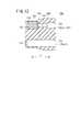
図6及び図7に示すように、気密シール100は、先端側の小径部102と、後端側の大径部104と、大径部104側から小径部102側へと縮径する縮径部(テーパ部)106とから構成された段付き円柱形状となっている。気密シール100には、延べ6本のロッド及びワイヤ、つまりロッド82a、82b及びワイヤ80a、80b(補強ロッド81a、81b)の往復分がそれぞれ挿通されて摺動する、6個の孔部110a〜110fが設けられている。気密シール100は、大径部104の外周面が連結シャフト18の内周面に密着固定されることで当該連結シャフト18内を仕切り、気体や液体の流通を遮断する遮断壁として機能する。勿論、先端動作部12の自由度を2自由度や4自由度等に変更し、ワイヤやロッドの本数を変更した場合には、気密シール100の孔部の数も変更すればよい。気密シール100は、手術中に隙間A(図4参照)から流入して該気密シール100に接触した後、再び隙間Aを介して患者の体腔22内へと戻る血液等の流れ(生体適合性)を考慮して、ゴムやシリコーン等によって形成されている。 As shown in FIGS. 6 and 7, the
図8A及び図8Bに示すように、各孔部110a〜110fは、ロッド82a、82b及びワイヤ80a、80bの連結シャフト18内での配列に対応して配置されており、孔部110a、110bにロッド82a、82bが挿通され、孔部110c、110dにワイヤ80a(補強ロッド81a)が挿通され、孔部110e、110fにワイヤ80b(補強ロッド81b)が挿通される。本実施形態の場合、孔部110c〜110fには、ワイヤ80a、80bの一部を囲繞した補強ロッド81a、81bが挿通及び摺動し、ワイヤ80a、80b自体は気密シール100に接触しない。 As shown in FIGS. 8A and 8B, the
気密シール100では、ロッド82a、82bが挿通される孔部110a、110bの構成が互いに同一であり、ワイヤ80a、80bが挿通される孔部110c〜110fの構成が互いに同一であることから、以下では、図8Bに示される孔部110bと孔部110cについて主に説明し、他の説明は省略する。 In the
図7及び図8Bに示すように、孔部110b(110a)は、小径部102の先端開口側(Z1側)に形成され、ロッド82b(82a)が摺動する摺動部(孔部)112と、摺動部112の後方(Z2側)に連続し、摺動部112より大径の拡径部(逃げ孔)114とから構成された2段形状の貫通孔であり、摺動部112がZ方向で小径部102に対応した配置となっている。 As shown in FIGS. 7 and 8B, the
摺動部112は、ロッド82bとの間で気密性を確保した状態で該ロッド82bが摺動可能な内径寸法であると共に、ロッド82bの摺動方向(Z方向)に短尺な長さL1からなる。これにより、摺動部112はロッド82bの移動に対してある程度柔軟(自由)に対応できるリップシールとして機能する。 The sliding
拡径部114には、気密シール100が連結シャフト18内に組み付けられる際、管状のガイドパイプ116が嵌挿され密着固定される。ガイドパイプ116の内径は、ロッド82bの外径より僅かに大径であり、ロッド82bの移動を邪魔しない構造となっている。つまり、ガイドパイプ116の内径>ロッド82a、82bの外径>摺動部112の内径、という寸法関係が設定されている。 When the
このようなガイドパイプ116は、例えばステンレス材等から構成され、少なくとも気密シール100を構成する材質よりも硬い材質となっている。なお、ガイドパイプ116が気密シール100よりも硬いとは、例えば、ガイドパイプ116に力を加えた際に、実質的に該ガイドパイプ116が変形するよりも先に気密シール100が変形する程度に硬さが異なる状態等をいう。 Such a
一方、孔部110c(110d〜110f)は、補強ロッド81a(81b)(ワイヤ80a、80b)が摺動する摺動部(孔部)118と、摺動部118の前方(Z1側)に連続し、摺動部118より大径の拡径部(逃げ孔)120と、摺動部118の後方(Z2側)に連続し、摺動部118より大径且つ拡径部120より小径の中径部(逃げ孔)122とから構成された3段形状の貫通孔であり、摺動部118がZ方向で大径部104に対応して配置されている。 On the other hand, the
摺動部118は、補強ロッド81aとの間で気密性を確保した状態で該補強ロッド81aが摺動可能な内径寸法であると共に、補強ロッド81aの摺動方向(Z方向)にやや長尺な長さL2からなる。図8Bから諒解されるように、摺動部118の摺動方向の長さL2は、摺動部112の長さL1よりも長い。 The sliding
摺動部118の前後にそれぞれ設けられた拡径部120及び中径部122は、ワイヤ80aが往復移動されてプーリ70aへの巻き掛け位置がX方向やY方向に変位した場合であっても、摺動部118に摺動している補強ロッド81aの一部が孔部110cの内面や開口縁部に当接することを防止する逃げ部として機能する。 The
気密シール100では、孔部110a、110bの間隔W1(図8A参照)をロッド82a、82bの間隔に対応するように設定し、孔部110c、110e(孔部110d、110f)の間隔W2をワイヤガイド部72a、72bの間隔に対応するように設定している。これにより、ロッド82aや補強ロッド81a等と摺動部112、118との間での軸中心の一致が図られ、円滑な摺動を確保することができる。 In the
図7及び図8Aに示すように、ワイヤ80a、80bに対応する孔部110c〜110fには、その外周面から各孔部110c〜110fの摺動部118へと連なる切込みであるスリット124が形成されている。スリット124を設けることにより、マニピュレータ10の組立時、例えば、ワイヤ80a、80bをプーリ70a、70bやギア78等との間に巻き掛ける際、補強ロッド81a、81bを装着したワイヤ80a、80bを予めループ状に形成しておき、該ループ状のワイヤ80a、80bをスリット124から孔部110c〜110fへと挿入することができる。そうすると、孔部110c〜110fへとワイヤ80a等を挿通させてからループ状に構成する場合に比べ、マニピュレータ10の組立性を大幅に向上させることができる。 As shown in FIGS. 7 and 8A, slits 124 are formed in the
なお、各スリット124は、連結シャフト18内に気密シール100が嵌挿された際に密着封止され、気密シール100のシール性を損うことはない。勿論、ワイヤの挿通後、各スリット124を接着剤等で接着して一層強固に封止してもよい。 Each
図2に戻り、マニピュレータ10は、気密シール100よりも先端動作部12側(Z1側)の連結シャフト18内に水や酵素洗浄剤等の洗浄液を注入できる洗浄ポート126を有する。洗浄ポート126は、蓋体128を着脱するだけで開閉可能であり、連結シャフト18内の気密シール100よりも先端側に洗浄液を容易に注入し、内部を洗浄することができる。 Returning to FIG. 2, the
次に、以上のように構成される本実施形態に係るマニピュレータ10の作用について説明する。 Next, the operation of the
図4に示すように、先端動作部12は、ロール軸、ヨー軸及びグリッパ軸の3自由度の機構を備え、複数の関節を有し、先端動作部12には各部に隙間Aが形成されている。勿論、1自由度の機構であっても関節は設けられる。従って、マニピュレータ10による手術中、図示しない気腹装置等によって体腔22内に封入された炭酸ガス等が(図1参照)、体腔22内が陽圧であるために、隙間Aを介して連結シャフト18内へリークしようとする。該リークが発生した場合には、体腔22の空間が収縮し、円滑な手術が難しくなる可能性がある。 As shown in FIG. 4, the distal
そこで、マニピュレータ10では、連結シャフト18内を先端動作部12側と駆動機構部側であるプーリボックス32側とに仕切る気密シール100を設けている。これにより、連結シャフト18の軸線方向での気密性が確保され、体腔22内のガス(気腹圧)が先端動作部12の隙間A(図4参照)等から連結シャフト18内を通って外部へとリークすることを防止する。 Therefore, the
具体的には、図7及び図8Bに示すように、気密シール100は、小径部102の外径D1が連結シャフト18の内径D0よりも小さく、大径部104の外径D2が連結シャフト18の内径D0よりも大きく構成されている。これにより、気密シール100が連結シャフト18内に圧入された際、大径部104が連結シャフト18の内壁面から圧縮力F(図7参照)を受けて内径方向に圧縮され、該内壁面に確実に密着する。従って、各孔部110a〜110fの各摺動部112、118でロッド82aや補強ロッド81a等との間がシールされ、さらに大径部104で連結シャフト18との間がシールされることにより、ロッド82aやワイヤ80a等の作動状態にかかわらず、連結シャフト18内の長手方向での気密性及び液密性が確保される。大径部104は連結シャフト18内に圧入のみで固定してもよいが、接着や溶着等によって固着させてもよい。 Specifically, as shown in FIGS. 7 and 8B, the
さらに、先端動作部12の隙間Aから浸入した血液等の液体が、連結シャフト18の内周面に沿って先端動作部12側からプーリボックス32側へと流通することも気密シール100によって阻止されるため、術後の連結シャフト18やプーリボックス32の洗浄等が容易となり、メンテナンス性を向上させることができる。しかも、気密シール100により連結シャフト18内の気密性が確保されていることから、体腔22内のガスが連結シャフト18の内部(先端側)を略密封するように機能する。このため、密封状態となったガスにより、血液等の液体が前記隙間Aから連結シャフト18内へと浸入すること事態も可及的に抑制することができる。 Further, the
気密シール100は、小径部102とテーパ状の縮径部106を有することから、連結シャフト18へと組み付ける挿入時、小径部102を先頭として連結シャフト18内に容易に挿入可能であり、マニピュレータ10の組立性を高めることができる。 Since the
ところで、本実施形態に係るマニピュレータ10の場合、ヨー軸及びロール軸は、複合入力部24の操作に基づきモータ50a、50b等を介してワイヤ80a、80bが往復移動する電動駆動であり、グリッパ軸は、トリガレバー36の操作に基づき機械的にロッド82a、82bが往復移動する手動駆動である。 By the way, in the case of the
ロッド82a、82bは、ワイヤ80a等のようにループ状に構成する必要がないことから、気密シール100への組み付け時、スリットがなくても孔部110a、110bへと容易に挿通させることができる。従って、孔部110a、110bの摺動部112は、スリット124が形成された孔部110c等に比べて気密性を確保し易いため、ロッド82a等の摺動方向での長さL1を短く設定し(図7及び図8B参照)、ロッド82a等との摺動抵抗を可及的に低減しながらも、気密性を十分に確保することが可能である。しかも、電動駆動に比べて摺動抵抗の影響を受け易い手動駆動のロッド82a、82bと、気密シール100との間の摺動抵抗が低減されるため、操作性が損なわれることもない。 Since the
一方、ワイヤ80a、80bは、気密シール100への組み付け時、上記のようにループ状に構成することが有効であることから、孔部110c〜110fにはループ状に構成した当該ワイヤ80a、80b(補強ロッド81a、81b)を挿入するためのスリット124を設けている。従って、孔部110c〜110fの摺動部118は、スリット124によって気密性が低下する可能性があることから、ワイヤ80a等の摺動方向での長さL2を摺動部112の長さL1よりも長く設定し(図7及び図8B参照)、気密性をより安定して確保できるように構成している。なお、ワイヤ80a等は電動駆動であるため、気密シール100との間の摺動抵抗が多少高くなったとしても該摺動抵抗がモータ50a、50bの定格出力以下であれば操作性に影響が及ぶことはほとんどなく、良好な操作性が維持される。 On the other hand, since it is effective to configure the
しかも、ワイヤ80a等の摺動方向において、摺動部118は、大径部104の少なくとも一部に対応して配置されると共に、該大径部104は連結シャフト18の内壁面から圧縮力F(図7参照)を受けて内径方向に圧縮される。このため、スリット124は、大径部104での圧縮を受けて一層確実に密着封止され、該スリット124からのガスリークが一層確実に防止される。すなわち、大径部104の外径D2は、連結シャフト18内に圧入可能な範囲でその内径D0よりもできるだけ大きく設定すれば、気密シール100の圧縮率が高まり、気密性が一層向上し、スリット124での気密性も一層確実に確保することが可能となる。 Moreover, in the sliding direction of the
本実施形態の場合、摺動部118には補強ロッド81a、81bが対応している。通常、ワイヤ80a、80bは、強度等を考慮して複数の線材をよった巻線で構成されているため、この巻線部分が摺動部118に対応している場合にはワイヤ80a等と摺動部118との間に隙間を生じ、該隙間を介してガスリークを生じる可能性がある。そこで、マニピュレータ10では、補強ロッド81a等が常に摺動部118に摺動する構成であることにより、気密シール100でのシール性を一層確実に確保することができる。気密性をより向上させるため、補強ロッド81a、81bをワイヤ80a、80bに接着剤等で接着してもよい。 In this embodiment, the reinforcing
図9に示すように、補強ロッド81a、81bの代わりに金属製等のロッド83a、83bの両端にワイヤ80a、80bを連結した構成や、パイプ85a、85bの両端にワイヤ80a、80bを連結し、該パイプ85a、85bの内部を接着剤87等でシールした構成等としてもよい。要は、気密シール100の摺動部118にワイヤ80a、80bを確実に密着させて円滑に摺動させることができる構成であればよい。 As shown in FIG. 9, instead of reinforcing
ここで、図7及び図8Bに示すように、気密シール100において、スリット124が形成された孔部110c〜110fの摺動部118と、スリット124が形成されていない孔部110a、110bの摺動部112とは、ワイヤやロッドの摺動方向での位置がずれている。すなわち、図8Bに示すように、摺動部112の摺動方向での中心位置112Zと、摺動部118の摺動方向での中心位置118Zとがずれており、中心位置112Zは小径部102の少なくとも一部に対応して配置され、中心位置118Zは大径部104の少なくとも一部に対応して配置される。 Here, as shown in FIGS. 7 and 8B, in the
従って、大径部104に連結シャフト18の内壁面から内径方向への圧縮力Fが付与されると共に、該圧縮力Fによって孔部110c〜110fのスリット124を確実に密着封止することができ、摺動部118も補強ロッド81a等とより確実に密着される。一方、摺動部118及び大径部104からZ方向でずれている孔部110a、110bの摺動部112には、圧縮力Fの影響がほとんどなく、つまり圧縮を受けない。このため、摺動部112がロッド82a、82bに対して過度に密着されて該ロッド82a、82bの円滑な移動が妨げられ、手動機構部であるトリガレバー36の操作性が低下することを有効に回避することができる。しかも、摺動部112は、連結シャフト18の内壁面よりも小さい外径D1に設定され、該内壁面からの圧縮を受けない小径部102に対応して配置されているため、摺動部112が過度に収縮することが一層確実に防止されている。 Therefore, the
圧縮力Fを受ける孔部110c〜110fには、摺動部118の前後に補強ロッド81a、81bの逃げ部となる拡径部120と中径部122が設けられている。このため、これら拡径部120と中径部122が圧縮力Fを吸収する機能も果たし、摺動部112に対して圧縮の影響が及ぶことが一層確実に回避される。一方、スリットが形成されていない孔部110a、110bには、摺動部112に連続し且つ摺動部112より大径の拡径部114が設けられており、拡径部114はロッドの摺動方向でスリット124が形成された孔部110c〜110f(摺動部118)の位置と重なっている。このため、大径部104が圧縮された場合でも、その圧縮の影響が拡径部114で有効に吸収され、手動で駆動されるロッド82a等の動作に影響を及ぼすことが有効に回避される。 The
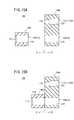
なお、図10Aに示すように、マニピュレータ10の組立時、理想的には、ロッド82a、82bのX方向及びY方向での中心位置(軸中心)と、摺動部112のX方向及びY方向での中心位置(軸中心)とが一致するように設定されており、ワイヤ80a等及び摺動部118についても略同様である。ところが、実際には、ロッド82a等の先端動作部12側やトリガレバー36側への取り付け位置が多少ずれてX方向やY方向にオフセットしてしまう可能性がある。そうすると、図10Bに示すように、ロッド82a等の軸中心と摺動部112の軸中心とがずれ、摺動部112がロッド82a等のオフセット分の過負荷を受け、摺動部112に隙間Bを生じ、場合によっては気密シール100が損傷し、シール性が低下する可能性がある。 As shown in FIG. 10A, when the
そこで、本実施形態の場合、ロッド82a、82bが挿通される孔部110a、110bの摺動部112に付設された拡径部114に、ガイド部としてのガイドパイプ116を嵌挿している(図7参照)。ガイドパイプ116を設けることにより、ロッド82a等の軸中心と摺動部112の軸中心とが一致している場合(図11A参照)には、摺動部112とガイドパイプ116の軸中心が一致する。一方、ロッド82a等の軸中心と摺動部112の軸中心とがずれている場合(図11B参照)には、ロッド82a、82bのオフセットと同時にガイドパイプ116がオフセットする。このため、ガイドパイプ116のオフセットに追従して拡径部114及び摺動部112も移動(変形)することから、摺動部112とロッド82a等の軸中心が一致する。従って、摺動部112に過負荷が生じ、気密シール100に損傷が生じることが回避され、シール性を確保することができる。 Therefore, in the case of the present embodiment, a
孔部110a等が摺動部112及び拡径部114からなる段付き構造とされ、拡径部114にガイドパイプ116を配置する構成とすることで、摺動部112とロッド82a等の軸中心を一致させることが一層容易となり、ロッド82a等のオフセットによる気密シール100の損傷を回避することができる。 The
ガイドパイプ116は、ロッド82a等の摺動により孔部110a等に生じる摺動方向と交差(直交)する方向(直角方向や半径方向)に作用する力を抑制するガイド部として機能するため、摺動部112での摩擦や磨耗を有効に低減することが可能となる。 The
また、拡径部114にガイドパイプ116を配置しておくことにより、高い密着性が要求される孔部110c〜110f側を強く圧縮した場合であっても、ガイドパイプ116がロッド82a等(ワイヤ80a等)のガイド部として機能するため、ロッド82a等(ワイヤ80a等)と摺動部112(118)との間の摺動抵抗が低減され、該摺動部112(118)の磨耗を低減することができる。換言すれば、連結シャフト18の内壁面と気密シール100の外壁面とを密着させるため、気密シール100を強く圧縮して連結シャフト18内に嵌挿した場合であっても、ガイド部として機能するガイドパイプ116により孔部110a〜110f(摺動部112、118)の圧縮が低減されるため、動力伝達部材であるロッド82aやワイヤ80a等と該孔部110a〜110f(摺動部112、118)との間の摺動抵抗を低減し、該孔部110a〜110f(摺動部112、118)の摩擦を低減することができる。 Further, by arranging the
ガイドパイプ116が拡径部114に密着固定されていれば、気密シール100の気密性を一層向上させることも可能となり、ガイドパイプ116の拡径部114からの脱落を防止することもできる。また、ガイドパイプ116が孔部110a〜110fにおける摺動部112、118の基端側(駆動機構部側)となるプーリボックス32側に配置されていることにより、当該ガイドパイプ116が連結シャフト18の先端側から体内へと脱落することを確実に防止することができる。 If the
ガイドパイプ116については、上記のように、ガイドパイプ116の内径>ロッド82a、82bの外径>摺動部112の内径、という寸法関係が規定しており、少なくともガイドパイプ116の内径は、摺動部112(孔部110a等)の内径と等しいか又はそれよりも大きく設定されることが望ましい。これにより、摺動部112(孔部110a等)と、これを挿通して摺動するロッド82a等との間に、必ず所定範囲の半径方向の力(押し付け力、シールする力)を発生させることができ、気密性が確実に確保される。なお、前記所定範囲とは、前記半径方向の力が0(ゼロ)になったり、摺動部112とロッド82a等との間に隙間が開いたり、摺動部112の摩擦や磨耗が増えたり、摺動部112が損傷したりすることがない程度のシール力である。 As described above, the
ガイドパイプ116の設置場所としては、上記のように軸線方向長さL1が短い摺動部112の近傍に設置することが効果的であるが、他の位置であってもよい。 As the installation location of the
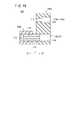
例えば、図12に示すように、摺動部112の前後に拡径部114をそれぞれ設け、両拡径部114にガイドパイプ116を設置してもよいし、一方の拡径部114にのみ設置してもよい。また、図13に示すように、補強ロッド81a、81b(ワイヤ80a、80b)が挿通される側の拡径部120(中径部122)に設置してもよい。そうするとスリット124が形成されていることから高い密着性が必要な孔部110c〜110fが強く圧縮された場合であっても、補強ロッド81a、81b(ワイヤ80a、80b)と摺動部118の摺動抵抗が低減され、該摺動部118の磨耗を低減することができる。さらに、図14に示すように、ガイドパイプ116を気密シール100の外部から接着等によって連結してもよい。 For example, as shown in FIG. 12, the
このように、ガイドパイプ116は、摺動部112(118)の近傍に設置されていればよく、摺動部112(118)の前後どちら側でも両側でも、またワイヤ80a等に対応する側でもよく、さらに、摺動部112(118)の軸中心と一致して配置できれば、気密シール100の外部に設置してもよい。 Thus, the
図15Aに示すように、連結シャフト18内を仕切るシール部材としては、上記のように一体的に形成された気密シール100に代えて、ワイヤ80a、80b側の第1シール部(第1部位)140aと、ロッド82a、82b側の第2シール部(第2部位)140bとを有した分割・連結構造の気密シール140を用いてもよい。このような気密シール140は、例えば、図15Bに示すように、第1シール部140aと第2シール部140bとを接着により一体化することにより、上記した気密シール100と略同様に使用可能である。 As shown in FIG. 15A, the seal member for partitioning the inside of the connecting
この場合、気密シール140では、ワイヤ80a、80b側の第1シール部140aと、ロッド82a、82b側の第2シール部140bとを分割構造としたことにより、連結シャフト18の内壁面から第1シール部140aに付与される圧縮力が、第2シール部140bの摺動部112へと影響することを一層確実に防止することができる。 In this case, in the
気密シール140の第1シール部140aと第2シール部140bの連結構造は、接着以外であってもよく、例えば、ガイドパイプ116による連結構造(図16参照)や、締結具であるボルト142及びナット144による連結構造(図17参照)でもよい。 The connection structure of the
図2に示すように、マニピュレータ10では、気密シール100よりも先端動作部12側(Z1側)の連結シャフト18内に臨む洗浄ポート126を配設しており、これにより気密シール100よりも先端側の連結シャフト18内を容易に洗浄することができる。 As shown in FIG. 2, in the
図18に示すように、洗浄ポート126は、気密シール100よりも連結シャフト18の基端側(Z2側)、例えばプーリボックス32に設け、操作部14と作業部16が装着された使用時には、外部から見えない位置に配置してもよい。この場合、図18及び図19に示すように、気密シール100の略中央に形成された洗浄用孔部132を挿通し、先端の噴射口130aが気密シール100の先端動作部12側に開口した洗浄チューブ130を洗浄ポート126に連通させておくことにより、マニピュレータ10の洗浄時、蓋体128を取り外して洗浄ポート126から洗浄チューブ130内へと洗浄液を流すことで、連結シャフト18内部や先端動作部12内部を容易に洗浄することができる。洗浄チューブ130の噴射口130aは、連結シャフト18内で開口しているが、手術時には洗浄ポート126が蓋体128によって閉塞されているため、当該洗浄チューブ130の内圧は所定圧に保持され、ここから体腔22内のガスがリークすることはない。 As shown in FIG. 18, the cleaning
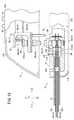
本発明は、例えば、図20に示すような手術用ロボットシステム200に適用することもできる。 The present invention can also be applied to a
手術用ロボットシステム200は、多関節型のロボットアーム202と、コンソール204とを有し、ロボットアーム202の先端には前記のマニピュレータ10と同じ機構が設けられている。ロボットアーム202の先端部208には、操作部14に代えて、内部に駆動部30を収納した基部14aが固定され、該基部14aに対して作業部16が着脱可能に取り付けられる。ロボットアーム202は、作業部16を移動させる手段であればよく、据置型に限らず、例えば自律移動型でもよい。コンソール204は、テーブル型、制御盤型等の構成を採り得る。 The
ロボットアーム202は、独立的な6以上の関節(回転軸やスライド軸等)を有すると、作業部16の位置及び向きを任意に設定できて好適である。先端のマニピュレータ10を構成する基部14aは、ロボットアーム202の先端部208と一体化している。マニピュレータ10は、前記のトリガレバー36の代わりに図示しないモータ(人手によって操作する入力部に連動するアクチュエータ)を有し、該モータが2本のロッド82a、82bを駆動する。 If the
ロボットアーム202は、コンソール204の作用下に動作し、プログラムによる自動動作や、コンソール204に設けられたジョイスティック206に倣った操作、及びこれらの複合的な動作をする構成にしてもよい。コンソール204は、前記のコントローラ29の機能を含んでいる。作業部16には、前記の先端動作部12が設けられている。 The
コンソール204には、操作指令部としての2つのジョイスティック206と、モニタ210が設けられている。図示を省略するが、2つのジョイスティック206により、2台のロボットアーム202を個別に操作することが可能である。2つのジョイスティック206は、両手で操作し易い位置に設けられている。モニタ210には、軟性鏡による画像等の情報が表示される。 The
ジョイスティック206は、上下動作、左右動作、捻り動作、及び傾動動作が可能であり、これらの動作に応じてロボットアーム202を動かすことができる。ジョイスティック206はマスターアームであってもよい。ロボットアーム202とコンソール204との間の通信手段は、有線、無線、ネットワーク又はこれらの組合せでよい。ジョイスティック206には、トリガレバー36が設けられており、該トリガレバー36を操作することによりモータ(図示せず)を介してグリッパを開閉駆動可能である。 The
このような手術用ロボットシステム200においても、上記の気密シール100、140を備えることにより、気腹圧のリークを有効に防止でき、さらに、洗浄や滅菌等のメンテナンス性を向上させることができる。 In such a
本発明は、上述の実施の形態に限らず、本発明の要旨を逸脱することなく、種々の構成乃至工程を採り得ることは勿論である。 The present invention is not limited to the above-described embodiment, and it is needless to say that various configurations and processes can be adopted without departing from the gist of the present invention.
10…マニピュレータ 12…先端動作部
14…操作部 16…作業部
18…連結シャフト 30…駆動部
80a、80b…ワイヤ 81a、81b…補強ロッド
82a、82b、83a、83b…ロッド100、140…気密シール
102…小径部 104…大径部
106…縮径部 110a〜110f…孔部
112、118…摺動部 114、120…拡径部
116…ガイドパイプ 124…スリット
126…洗浄ポート 130…洗浄チューブDESCRIPTION OF
Claims (7)
Translated fromJapanese前記シャフト内に挿通される複数の動力伝達部材と、
前記シャフトの一端側に設けられ、前記動力伝達部材を軸線方向に進退駆動する駆動機構部と、
前記シャフトの他端側に設けられ、前記動力伝達部材の前記進退駆動によって動作される先端動作部と、
前記複数の動力伝達部材がそれぞれ摺動可能に挿通される複数の孔部が形成され、前記シャフトの内面に対して密着配置されることにより、該シャフト内を前記先端動作部側と前記駆動機構部側とに仕切るシール部材と、
を備え、
前記複数の孔部のうち、少なくとも一部の孔部近傍には、ガイド部が配置されていることを特徴とする医療用マニピュレータ。A hollow shaft,
A plurality of power transmission members inserted into the shaft;
A drive mechanism that is provided on one end of the shaft and drives the power transmission member to advance and retreat in the axial direction;
Provided on the other end side of the shaft, and operated by the forward / backward drive of the power transmission member,
A plurality of hole portions through which the plurality of power transmission members are slidably inserted are formed and arranged in close contact with the inner surface of the shaft, whereby the tip operating portion side and the drive mechanism are formed inside the shaft. A sealing member for partitioning with a part side;
With
A medical manipulator characterized in that a guide portion is disposed in the vicinity of at least some of the plurality of holes.
前記ガイド部は、前記シール部材を構成する材質よりも硬い材質からなるガイドパイプであることを特徴とする医療用マニピュレータ。The medical manipulator according to claim 1, wherein
The medical manipulator, wherein the guide portion is a guide pipe made of a material harder than a material constituting the seal member.
前記ガイドパイプの内径は、前記孔部の内径と等しいか又はそれよりも大きいことを特徴とする医療用マニピュレータ。The medical manipulator according to claim 2,
The medical manipulator characterized in that an inner diameter of the guide pipe is equal to or larger than an inner diameter of the hole.
前記ガイドパイプは、前記複数の孔部よりも前記駆動機構部側に配置されていることを特徴とする医療用マニピュレータ。The medical manipulator according to claim 2 or 3,
The medical manipulator, wherein the guide pipe is disposed closer to the drive mechanism than the plurality of holes.
前記シール部材は、前記複数の孔部に連続し且つ該孔部より大径に形成され、該孔部に挿通された前記動力伝達部材が挿通する拡径部を有し、該拡径部に前記ガイドパイプが配置されていることを特徴とする医療用マニピュレータ。The medical manipulator according to any one of claims 2 to 4,
The seal member has a diameter-enlarged portion that is continuous with the plurality of holes and has a larger diameter than the hole, and through which the power transmission member inserted through the hole is inserted. A medical manipulator in which the guide pipe is disposed.
前記駆動機構部は、前記動力伝達部材のうちの一部を電動で駆動する電動機構部と、残りを手動で駆動する手動機構部とを有し、
前記シール部材は、前記複数の孔部に連続し且つ該孔部より大径に形成され、該孔部に挿通された前記動力伝達部材が挿通する拡径部を有し、
前記ガイドパイプは、前記手動機構部に接続されている前記動力伝達部材が挿通される拡径部に配置されていることを特徴とする医療用マニピュレータ。The medical manipulator according to any one of claims 2 to 4,
The drive mechanism unit includes an electric mechanism unit that electrically drives a part of the power transmission member, and a manual mechanism unit that manually drives the rest,
The seal member has a diameter-enlarged portion that is continuous with the plurality of holes and formed to have a larger diameter than the holes, and through which the power transmission member inserted through the holes is inserted.
The medical manipulator, wherein the guide pipe is disposed in an enlarged diameter portion through which the power transmission member connected to the manual mechanism portion is inserted.
前記ガイドパイプの外表面は、前記拡径部の内表面に密着していることを特徴とする医療用マニピュレータ。The medical manipulator according to claim 5 or 6,
The medical manipulator, wherein an outer surface of the guide pipe is in close contact with an inner surface of the enlarged diameter portion.
Priority Applications (1)
| Application Number | Priority Date | Filing Date | Title |
|---|---|---|---|
| JP2009195858AJP2011045500A (en) | 2009-08-26 | 2009-08-26 | Medical manipulator |
Applications Claiming Priority (1)
| Application Number | Priority Date | Filing Date | Title |
|---|---|---|---|
| JP2009195858AJP2011045500A (en) | 2009-08-26 | 2009-08-26 | Medical manipulator |
Publications (1)
| Publication Number | Publication Date |
|---|---|
| JP2011045500Atrue JP2011045500A (en) | 2011-03-10 |
Family
ID=43832436
Family Applications (1)
| Application Number | Title | Priority Date | Filing Date |
|---|---|---|---|
| JP2009195858AWithdrawnJP2011045500A (en) | 2009-08-26 | 2009-08-26 | Medical manipulator |
Country Status (1)
| Country | Link |
|---|---|
| JP (1) | JP2011045500A (en) |
Cited By (40)
| Publication number | Priority date | Publication date | Assignee | Title |
|---|---|---|---|---|
| JP2014531219A (en)* | 2011-07-11 | 2014-11-27 | ボード オブ リージェンツ オブ ザ ユニバーシティ オブ ネブラスカ | Robotic surgical device, system, and related methods |
| US9579088B2 (en) | 2007-02-20 | 2017-02-28 | Board Of Regents Of The University Of Nebraska | Methods, systems, and devices for surgical visualization and device manipulation |
| US9743987B2 (en) | 2013-03-14 | 2017-08-29 | Board Of Regents Of The University Of Nebraska | Methods, systems, and devices relating to robotic surgical devices, end effectors, and controllers |
| US9757187B2 (en) | 2011-06-10 | 2017-09-12 | Board Of Regents Of The University Of Nebraska | Methods, systems, and devices relating to surgical end effectors |
| US9770305B2 (en) | 2012-08-08 | 2017-09-26 | Board Of Regents Of The University Of Nebraska | Robotic surgical devices, systems, and related methods |
| US9883911B2 (en) | 2006-06-22 | 2018-02-06 | Board Of Regents Of The University Of Nebraska | Multifunctional operational component for robotic devices |
| US9888966B2 (en) | 2013-03-14 | 2018-02-13 | Board Of Regents Of The University Of Nebraska | Methods, systems, and devices relating to force control surgical systems |
| US9956043B2 (en) | 2007-07-12 | 2018-05-01 | Board Of Regents Of The University Of Nebraska | Methods, systems, and devices for surgical access and procedures |
| JP2018521870A (en)* | 2015-07-22 | 2018-08-09 | シーエムアール サージカル リミテッドCmr Surgical Limited | Robot arm |
| US10219870B2 (en) | 2012-05-01 | 2019-03-05 | Board Of Regents Of The University Of Nebraska | Single site robotic device and related systems and methods |
| US10307199B2 (en) | 2006-06-22 | 2019-06-04 | Board Of Regents Of The University Of Nebraska | Robotic surgical devices and related methods |
| US10335024B2 (en) | 2007-08-15 | 2019-07-02 | Board Of Regents Of The University Of Nebraska | Medical inflation, attachment and delivery devices and related methods |
| US10342561B2 (en) | 2014-09-12 | 2019-07-09 | Board Of Regents Of The University Of Nebraska | Quick-release end effectors and related systems and methods |
| US10376322B2 (en) | 2014-11-11 | 2019-08-13 | Board Of Regents Of The University Of Nebraska | Robotic device with compact joint design and related systems and methods |
| US10470828B2 (en) | 2012-06-22 | 2019-11-12 | Board Of Regents Of The University Of Nebraska | Local control robotic surgical devices and related methods |
| WO2020044994A1 (en)* | 2018-08-28 | 2020-03-05 | 株式会社メディカロイド | Robotic surgical apparatus |
| US10582973B2 (en) | 2012-08-08 | 2020-03-10 | Virtual Incision Corporation | Robotic surgical devices, systems, and related methods |
| JP2020073013A (en)* | 2017-05-01 | 2020-05-14 | 株式会社メディカロイド | Surgical system and medical treatment tool |
| US10667883B2 (en) | 2013-03-15 | 2020-06-02 | Virtual Incision Corporation | Robotic surgical devices, systems, and related methods |
| US10702347B2 (en) | 2016-08-30 | 2020-07-07 | The Regents Of The University Of California | Robotic device with compact joint design and an additional degree of freedom and related systems and methods |
| US10722319B2 (en) | 2016-12-14 | 2020-07-28 | Virtual Incision Corporation | Releasable attachment device for coupling to medical devices and related systems and methods |
| US10751136B2 (en) | 2016-05-18 | 2020-08-25 | Virtual Incision Corporation | Robotic surgical devices, systems and related methods |
| US10806538B2 (en) | 2015-08-03 | 2020-10-20 | Virtual Incision Corporation | Robotic surgical devices, systems, and related methods |
| JP2021049276A (en)* | 2019-09-26 | 2021-04-01 | 株式会社メディカロイド | Surgical instrument |
| US10966700B2 (en) | 2013-07-17 | 2021-04-06 | Virtual Incision Corporation | Robotic surgical devices, systems and related methods |
| US11013564B2 (en) | 2018-01-05 | 2021-05-25 | Board Of Regents Of The University Of Nebraska | Single-arm robotic device with compact joint design and related systems and methods |
| US11051894B2 (en) | 2017-09-27 | 2021-07-06 | Virtual Incision Corporation | Robotic surgical devices with tracking camera technology and related systems and methods |
| US11071600B2 (en) | 2017-05-01 | 2021-07-27 | Medicaroid Corporation | Medical treatment tool and surgical system |
| US11173617B2 (en) | 2016-08-25 | 2021-11-16 | Board Of Regents Of The University Of Nebraska | Quick-release end effector tool interface |
| JP2021186231A (en)* | 2020-05-29 | 2021-12-13 | 株式会社メディカロイド | Surgical instrument |
| US11284958B2 (en) | 2016-11-29 | 2022-03-29 | Virtual Incision Corporation | User controller with user presence detection and related systems and methods |
| US11357595B2 (en) | 2016-11-22 | 2022-06-14 | Board Of Regents Of The University Of Nebraska | Gross positioning device and related systems and methods |
| JP2022097546A (en)* | 2018-12-26 | 2022-06-30 | 川崎重工業株式会社 | Translation methods for manipulator arms, robotic systems and surgical instruments used in surgical systems |
| US11737658B2 (en) | 2018-12-26 | 2023-08-29 | Kawasaki Jukogyo Kabushiki Kaisha | Manipulator arm and patient-side system for surgical system |
| US11883065B2 (en) | 2012-01-10 | 2024-01-30 | Board Of Regents Of The University Of Nebraska | Methods, systems, and devices for surgical access and insertion |
| US11903658B2 (en) | 2019-01-07 | 2024-02-20 | Virtual Incision Corporation | Robotically assisted surgical system and related devices and methods |
| WO2024047825A1 (en)* | 2022-08-31 | 2024-03-07 | 朝日サージカルロボティクス株式会社 | Cleaning nozzle and manipulator auxiliary device |
| US12150722B2 (en) | 2020-07-06 | 2024-11-26 | Virtual Incision Corporation | Surgical robot positioning system and related devices and methods |
| US12156710B2 (en) | 2011-10-03 | 2024-12-03 | Virtual Incision Corporation | Robotic surgical devices, systems and related methods |
| US12295680B2 (en) | 2012-08-08 | 2025-05-13 | Board Of Regents Of The University Of Nebraska | Robotic surgical devices, systems and related methods |
- 2009
- 2009-08-26JPJP2009195858Apatent/JP2011045500A/ennot_activeWithdrawn
Cited By (89)
| Publication number | Priority date | Publication date | Assignee | Title |
|---|---|---|---|---|
| US10959790B2 (en) | 2006-06-22 | 2021-03-30 | Board Of Regents Of The University Of Nebraska | Multifunctional operational component for robotic devices |
| US10376323B2 (en) | 2006-06-22 | 2019-08-13 | Board Of Regents Of The University Of Nebraska | Multifunctional operational component for robotic devices |
| US9883911B2 (en) | 2006-06-22 | 2018-02-06 | Board Of Regents Of The University Of Nebraska | Multifunctional operational component for robotic devices |
| US10307199B2 (en) | 2006-06-22 | 2019-06-04 | Board Of Regents Of The University Of Nebraska | Robotic surgical devices and related methods |
| US9579088B2 (en) | 2007-02-20 | 2017-02-28 | Board Of Regents Of The University Of Nebraska | Methods, systems, and devices for surgical visualization and device manipulation |
| US10695137B2 (en) | 2007-07-12 | 2020-06-30 | Board Of Regents Of The University Of Nebraska | Methods, systems, and devices for surgical access and procedures |
| US9956043B2 (en) | 2007-07-12 | 2018-05-01 | Board Of Regents Of The University Of Nebraska | Methods, systems, and devices for surgical access and procedures |
| US10335024B2 (en) | 2007-08-15 | 2019-07-02 | Board Of Regents Of The University Of Nebraska | Medical inflation, attachment and delivery devices and related methods |
| US11832871B2 (en) | 2011-06-10 | 2023-12-05 | Board Of Regents Of The University Of Nebraska | Methods, systems, and devices relating to surgical end effectors |
| US10350000B2 (en) | 2011-06-10 | 2019-07-16 | Board Of Regents Of The University Of Nebraska | Methods, systems, and devices relating to surgical end effectors |
| US9757187B2 (en) | 2011-06-10 | 2017-09-12 | Board Of Regents Of The University Of Nebraska | Methods, systems, and devices relating to surgical end effectors |
| US11065050B2 (en) | 2011-06-10 | 2021-07-20 | Board Of Regents Of The University Of Nebraska | Methods, systems, and devices relating to surgical end effectors |
| US10111711B2 (en) | 2011-07-11 | 2018-10-30 | Board Of Regents Of The University Of Nebraska | Robotic surgical devices, systems, and related methods |
| US11032125B2 (en) | 2011-07-11 | 2021-06-08 | Board Of Regents Of The University Of Nebraska | Robotic surgical devices, systems and related methods |
| US11595242B2 (en) | 2011-07-11 | 2023-02-28 | Board Of Regents Of The University Of Nebraska | Robotic surgical devices, systems and related methods |
| US12323289B2 (en) | 2011-07-11 | 2025-06-03 | Board Of Regents Of The University Of Nebraska | Robotic surgical devices, systems, and related methods |
| US11909576B2 (en) | 2011-07-11 | 2024-02-20 | Board Of Regents Of The University Of Nebraska | Robotic surgical devices, systems, and related methods |
| JP2014531219A (en)* | 2011-07-11 | 2014-11-27 | ボード オブ リージェンツ オブ ザ ユニバーシティ オブ ネブラスカ | Robotic surgical device, system, and related methods |
| US12156710B2 (en) | 2011-10-03 | 2024-12-03 | Virtual Incision Corporation | Robotic surgical devices, systems and related methods |
| US11883065B2 (en) | 2012-01-10 | 2024-01-30 | Board Of Regents Of The University Of Nebraska | Methods, systems, and devices for surgical access and insertion |
| US10219870B2 (en) | 2012-05-01 | 2019-03-05 | Board Of Regents Of The University Of Nebraska | Single site robotic device and related systems and methods |
| US11529201B2 (en) | 2012-05-01 | 2022-12-20 | Board Of Regents Of The University Of Nebraska | Single site robotic device and related systems and methods |
| US12171512B2 (en) | 2012-05-01 | 2024-12-24 | Board Of Regents Of The University Of Nebraska | Single site robotic device and related systems and methods |
| US11819299B2 (en) | 2012-05-01 | 2023-11-21 | Board Of Regents Of The University Of Nebraska | Single site robotic device and related systems and methods |
| US10470828B2 (en) | 2012-06-22 | 2019-11-12 | Board Of Regents Of The University Of Nebraska | Local control robotic surgical devices and related methods |
| US11484374B2 (en) | 2012-06-22 | 2022-11-01 | Board Of Regents Of The University Of Nebraska | Local control robotic surgical devices and related methods |
| US11617626B2 (en) | 2012-08-08 | 2023-04-04 | Board Of Regents Of The University Of Nebraska | Robotic surgical devices, systems and related methods |
| US10582973B2 (en) | 2012-08-08 | 2020-03-10 | Virtual Incision Corporation | Robotic surgical devices, systems, and related methods |
| US10624704B2 (en) | 2012-08-08 | 2020-04-21 | Board Of Regents Of The University Of Nebraska | Robotic devices with on board control and related systems and devices |
| US11051895B2 (en) | 2012-08-08 | 2021-07-06 | Board Of Regents Of The University Of Nebraska | Robotic surgical devices, systems, and related methods |
| US12295680B2 (en) | 2012-08-08 | 2025-05-13 | Board Of Regents Of The University Of Nebraska | Robotic surgical devices, systems and related methods |
| US11832902B2 (en) | 2012-08-08 | 2023-12-05 | Virtual Incision Corporation | Robotic surgical devices, systems, and related methods |
| US9770305B2 (en) | 2012-08-08 | 2017-09-26 | Board Of Regents Of The University Of Nebraska | Robotic surgical devices, systems, and related methods |
| US12070282B2 (en) | 2013-03-14 | 2024-08-27 | Board Of Regents Of The University Of Nebraska | Methods, systems, and devices relating to force control surgical systems |
| US11806097B2 (en) | 2013-03-14 | 2023-11-07 | Board Of Regents Of The University Of Nebraska | Methods, systems, and devices relating to robotic surgical devices, end effectors, and controllers |
| US9888966B2 (en) | 2013-03-14 | 2018-02-13 | Board Of Regents Of The University Of Nebraska | Methods, systems, and devices relating to force control surgical systems |
| US12336777B2 (en) | 2013-03-14 | 2025-06-24 | Board Of Regents Of The University Of Nebraska | Methods, systems, and devices relating to robotic surgical devices, end effectors, and controllers |
| US10743949B2 (en) | 2013-03-14 | 2020-08-18 | Board Of Regents Of The University Of Nebraska | Methods, systems, and devices relating to force control surgical systems |
| US9743987B2 (en) | 2013-03-14 | 2017-08-29 | Board Of Regents Of The University Of Nebraska | Methods, systems, and devices relating to robotic surgical devices, end effectors, and controllers |
| US10603121B2 (en) | 2013-03-14 | 2020-03-31 | Board Of Regents Of The University Of Nebraska | Methods, systems, and devices relating to robotic surgical devices, end effectors, and controllers |
| US10667883B2 (en) | 2013-03-15 | 2020-06-02 | Virtual Incision Corporation | Robotic surgical devices, systems, and related methods |
| US11633253B2 (en) | 2013-03-15 | 2023-04-25 | Virtual Incision Corporation | Robotic surgical devices, systems, and related methods |
| US10966700B2 (en) | 2013-07-17 | 2021-04-06 | Virtual Incision Corporation | Robotic surgical devices, systems and related methods |
| US11826032B2 (en) | 2013-07-17 | 2023-11-28 | Virtual Incision Corporation | Robotic surgical devices, systems and related methods |
| US12390240B2 (en) | 2014-09-12 | 2025-08-19 | Virtual Incision Corporation | Quick-release end effectors and related systems and methods |
| US10342561B2 (en) | 2014-09-12 | 2019-07-09 | Board Of Regents Of The University Of Nebraska | Quick-release end effectors and related systems and methods |
| US11576695B2 (en) | 2014-09-12 | 2023-02-14 | Virtual Incision Corporation | Quick-release end effectors and related systems and methods |
| US11406458B2 (en) | 2014-11-11 | 2022-08-09 | Board Of Regents Of The University Of Nebraska | Robotic device with compact joint design and related systems and methods |
| US10376322B2 (en) | 2014-11-11 | 2019-08-13 | Board Of Regents Of The University Of Nebraska | Robotic device with compact joint design and related systems and methods |
| US12096999B2 (en) | 2014-11-11 | 2024-09-24 | Board Of Regents Of The University Of Nebraska | Robotic device with compact joint design and related systems and methods |
| JP2018521870A (en)* | 2015-07-22 | 2018-08-09 | シーエムアール サージカル リミテッドCmr Surgical Limited | Robot arm |
| US10806538B2 (en) | 2015-08-03 | 2020-10-20 | Virtual Incision Corporation | Robotic surgical devices, systems, and related methods |
| US11872090B2 (en) | 2015-08-03 | 2024-01-16 | Virtual Incision Corporation | Robotic surgical devices, systems, and related methods |
| US10751136B2 (en) | 2016-05-18 | 2020-08-25 | Virtual Incision Corporation | Robotic surgical devices, systems and related methods |
| US12383355B2 (en) | 2016-05-18 | 2025-08-12 | Virtual Incision Corporation | Robotic surgical devices, systems and related methods |
| US11826014B2 (en) | 2016-05-18 | 2023-11-28 | Virtual Incision Corporation | Robotic surgical devices, systems and related methods |
| US11173617B2 (en) | 2016-08-25 | 2021-11-16 | Board Of Regents Of The University Of Nebraska | Quick-release end effector tool interface |
| US10702347B2 (en) | 2016-08-30 | 2020-07-07 | The Regents Of The University Of California | Robotic device with compact joint design and an additional degree of freedom and related systems and methods |
| US12274517B2 (en) | 2016-08-30 | 2025-04-15 | Board Of Regents Of The University Of Nebraska | Robotic device with compact joint design and an additional degree of freedom and related systems and methods |
| US12109079B2 (en) | 2016-11-22 | 2024-10-08 | Board Of Regents Of The University Of Nebraska | Gross positioning device and related systems and methods |
| US11357595B2 (en) | 2016-11-22 | 2022-06-14 | Board Of Regents Of The University Of Nebraska | Gross positioning device and related systems and methods |
| US11813124B2 (en) | 2016-11-22 | 2023-11-14 | Board Of Regents Of The University Of Nebraska | Gross positioning device and related systems and methods |
| US12114953B2 (en) | 2016-11-29 | 2024-10-15 | Virtual Incision Corporation | User controller with user presence detection and related systems and methods |
| US11701193B2 (en) | 2016-11-29 | 2023-07-18 | Virtual Incision Corporation | User controller with user presence detection and related systems and methods |
| US11284958B2 (en) | 2016-11-29 | 2022-03-29 | Virtual Incision Corporation | User controller with user presence detection and related systems and methods |
| US11786334B2 (en) | 2016-12-14 | 2023-10-17 | Virtual Incision Corporation | Releasable attachment device for coupling to medical devices and related systems and methods |
| US10722319B2 (en) | 2016-12-14 | 2020-07-28 | Virtual Incision Corporation | Releasable attachment device for coupling to medical devices and related systems and methods |
| US11071600B2 (en) | 2017-05-01 | 2021-07-27 | Medicaroid Corporation | Medical treatment tool and surgical system |
| JP2020073013A (en)* | 2017-05-01 | 2020-05-14 | 株式会社メディカロイド | Surgical system and medical treatment tool |
| US11051894B2 (en) | 2017-09-27 | 2021-07-06 | Virtual Incision Corporation | Robotic surgical devices with tracking camera technology and related systems and methods |
| US11974824B2 (en) | 2017-09-27 | 2024-05-07 | Virtual Incision Corporation | Robotic surgical devices with tracking camera technology and related systems and methods |
| US12343098B2 (en) | 2017-09-27 | 2025-07-01 | Virtual Incision Corporation | Robotic surgical devices with tracking camera technology and related systems and methods |
| US11950867B2 (en) | 2018-01-05 | 2024-04-09 | Board Of Regents Of The University Of Nebraska | Single-arm robotic device with compact joint design and related systems and methods |
| US11504196B2 (en) | 2018-01-05 | 2022-11-22 | Board Of Regents Of The University Of Nebraska | Single-arm robotic device with compact joint design and related systems and methods |
| US11013564B2 (en) | 2018-01-05 | 2021-05-25 | Board Of Regents Of The University Of Nebraska | Single-arm robotic device with compact joint design and related systems and methods |
| US12303221B2 (en) | 2018-01-05 | 2025-05-20 | Board Of Regents Of The University Of Nebraska | Single-arm robotic device with compact joint design and related systems and methods |
| WO2020044994A1 (en)* | 2018-08-28 | 2020-03-05 | 株式会社メディカロイド | Robotic surgical apparatus |
| JPWO2020044994A1 (en)* | 2018-08-28 | 2020-09-10 | 株式会社メディカロイド | Robot surgical instruments |
| JP7345008B2 (en) | 2018-12-26 | 2023-09-14 | 川崎重工業株式会社 | Methods for translating manipulator arms, robotic systems and surgical instruments used in surgical systems |
| US11744444B2 (en) | 2018-12-26 | 2023-09-05 | Kawasaki Jukogyo Kabushiki Kaisha | Manipulator arm and patient-side system for surgical system |
| JP2022097546A (en)* | 2018-12-26 | 2022-06-30 | 川崎重工業株式会社 | Translation methods for manipulator arms, robotic systems and surgical instruments used in surgical systems |
| US11737658B2 (en) | 2018-12-26 | 2023-08-29 | Kawasaki Jukogyo Kabushiki Kaisha | Manipulator arm and patient-side system for surgical system |
| US11903658B2 (en) | 2019-01-07 | 2024-02-20 | Virtual Incision Corporation | Robotically assisted surgical system and related devices and methods |
| JP2021049276A (en)* | 2019-09-26 | 2021-04-01 | 株式会社メディカロイド | Surgical instrument |
| JP7009428B2 (en) | 2019-09-26 | 2022-01-25 | 株式会社メディカロイド | Surgical instruments |
| JP2021186231A (en)* | 2020-05-29 | 2021-12-13 | 株式会社メディカロイド | Surgical instrument |
| JP7477368B2 (en) | 2020-05-29 | 2024-05-01 | 株式会社メディカロイド | Surgical instruments |
| US12150722B2 (en) | 2020-07-06 | 2024-11-26 | Virtual Incision Corporation | Surgical robot positioning system and related devices and methods |
| WO2024047825A1 (en)* | 2022-08-31 | 2024-03-07 | 朝日サージカルロボティクス株式会社 | Cleaning nozzle and manipulator auxiliary device |
Similar Documents
| Publication | Publication Date | Title |
|---|---|---|
| JP2011045500A (en) | Medical manipulator | |
| EP2444012B1 (en) | Manipulator | |
| WO2011024888A1 (en) | Medical manipulator | |
| US9132456B2 (en) | Cleaning method for a working mechanism for medical manipulator | |
| KR102009222B1 (en) | Curved cannula, robotic manipulator and surgical port | |
| KR101734114B1 (en) | Curved cannula, robotic manipulator and surgical port | |
| KR101948703B1 (en) | Curved cannula and robotic manipulator | |
| KR101540285B1 (en) | Sterile drape interface for robotic surgical instrument | |
| KR102118008B1 (en) | Curved cannula surgical system | |
| EP3057515B1 (en) | Wrist mechanism for surgical instrument | |
| US8585583B2 (en) | Working mechanism for medical manipulator | |
| US7887640B2 (en) | Medical manipulator and cleaning method for medical manipulator | |
| JP2016120313A (en) | Surgical accessory clamp and system | |
| JP2011200593A (en) | Medical instrument | |
| JP2010273978A (en) | Medical manipulator | |
| JP2011206191A (en) | Medical manipulator | |
| CN120203795A (en) | Surgical Instruments and Medical Systems |
Legal Events
| Date | Code | Title | Description |
|---|---|---|---|
| A300 | Application deemed to be withdrawn because no request for examination was validly filed | Free format text:JAPANESE INTERMEDIATE CODE: A300 Effective date:20121106 |