JP2011044394A - Light guide body used for lighting fixture for vehicle - Google Patents
Light guide body used for lighting fixture for vehicleDownload PDFInfo
- Publication number
- JP2011044394A JP2011044394AJP2009193310AJP2009193310AJP2011044394AJP 2011044394 AJP2011044394 AJP 2011044394AJP 2009193310 AJP2009193310 AJP 2009193310AJP 2009193310 AJP2009193310 AJP 2009193310AJP 2011044394 AJP2011044394 AJP 2011044394A
- Authority
- JP
- Japan
- Prior art keywords
- light guide
- light
- outer peripheral
- peripheral surface
- surface portion
- Prior art date
- Legal status (The legal status is an assumption and is not a legal conclusion. Google has not performed a legal analysis and makes no representation as to the accuracy of the status listed.)
- Pending
Links
- 230000002093peripheral effectEffects0.000claimsdescription44
- 239000000463materialSubstances0.000claimsdescription14
- 239000011248coating agentSubstances0.000claimsdescription5
- 238000000576coating methodMethods0.000claimsdescription5
- 229920005989resinPolymers0.000abstractdescription6
- 239000011347resinSubstances0.000abstractdescription6
- 239000003513alkaliSubstances0.000abstract2
- 238000004519manufacturing processMethods0.000abstract1
- 239000000758substrateSubstances0.000description19
- 238000003860storageMethods0.000description5
- 210000000078clawAnatomy0.000description4
- 238000003780insertionMethods0.000description4
- 230000037431insertionEffects0.000description4
- PXGOKWXKJXAPGV-UHFFFAOYSA-NFluorineChemical compoundFFPXGOKWXKJXAPGV-UHFFFAOYSA-N0.000description2
- 239000004743PolypropyleneSubstances0.000description2
- VYPSYNLAJGMNEJ-UHFFFAOYSA-NSilicium dioxideChemical compoundO=[Si]=OVYPSYNLAJGMNEJ-UHFFFAOYSA-N0.000description2
- 229920000122acrylonitrile butadiene styrenePolymers0.000description2
- 230000008901benefitEffects0.000description2
- 230000008859changeEffects0.000description2
- 238000004040coloringMethods0.000description2
- 229910052731fluorineInorganic materials0.000description2
- 239000011737fluorineSubstances0.000description2
- WABPQHHGFIMREM-UHFFFAOYSA-Nlead(0)Chemical compound[Pb]WABPQHHGFIMREM-UHFFFAOYSA-N0.000description2
- 238000000034methodMethods0.000description2
- 239000003973paintSubstances0.000description2
- 239000002245particleSubstances0.000description2
- 229920003229poly(methyl methacrylate)Polymers0.000description2
- 229920000515polycarbonatePolymers0.000description2
- 239000004417polycarbonateSubstances0.000description2
- 239000004926polymethyl methacrylateSubstances0.000description2
- 229920001155polypropylenePolymers0.000description2
- 229920005992thermoplastic resinPolymers0.000description2
- 239000004642PolyimideSubstances0.000description1
- 230000004308accommodationEffects0.000description1
- NIXOWILDQLNWCW-UHFFFAOYSA-Nacrylic acid groupChemical groupC(C=C)(=O)ONIXOWILDQLNWCW-UHFFFAOYSA-N0.000description1
- 229910052782aluminiumInorganic materials0.000description1
- XAGFODPZIPBFFR-UHFFFAOYSA-NaluminiumChemical compound[Al]XAGFODPZIPBFFR-UHFFFAOYSA-N0.000description1
- 238000005422blastingMethods0.000description1
- 239000000919ceramicSubstances0.000description1
- 235000019646color toneNutrition0.000description1
- 239000003086colorantSubstances0.000description1
- 238000005520cutting processMethods0.000description1
- 238000013461designMethods0.000description1
- 238000010586diagramMethods0.000description1
- 238000005516engineering processMethods0.000description1
- 230000002349favourable effectEffects0.000description1
- 239000011521glassSubstances0.000description1
- 238000001746injection mouldingMethods0.000description1
- 150000002484inorganic compoundsChemical class0.000description1
- 229910010272inorganic materialInorganic materials0.000description1
- 230000001788irregularEffects0.000description1
- 229910052751metalInorganic materials0.000description1
- 239000002184metalSubstances0.000description1
- 239000007769metal materialSubstances0.000description1
- 229910044991metal oxideInorganic materials0.000description1
- 150000004706metal oxidesChemical class0.000description1
- 238000012986modificationMethods0.000description1
- 230000004048modificationEffects0.000description1
- 238000000465mouldingMethods0.000description1
- 239000013307optical fiberSubstances0.000description1
- TWNQGVIAIRXVLR-UHFFFAOYSA-Noxo(oxoalumanyloxy)alumaneChemical compoundO=[Al]O[Al]=OTWNQGVIAIRXVLR-UHFFFAOYSA-N0.000description1
- 239000004033plasticSubstances0.000description1
- 229920003023plasticPolymers0.000description1
- 238000007747platingMethods0.000description1
- 229920000728polyesterPolymers0.000description1
- 229920001721polyimidePolymers0.000description1
- -1polypropylenePolymers0.000description1
- 239000000843powderSubstances0.000description1
- 230000008569processEffects0.000description1
- 235000012239silicon dioxideNutrition0.000description1
- 239000000377silicon dioxideSubstances0.000description1
- 238000004381surface treatmentMethods0.000description1
- 238000012546transferMethods0.000description1
- 238000007740vapor depositionMethods0.000description1
Images


Landscapes
- Non-Portable Lighting Devices Or Systems Thereof (AREA)
- Lighting Device Outwards From Vehicle And Optical Signal (AREA)
Abstract
Description
Translated fromJapanese本発明は、車両用灯具(例えば、車両のドアミラー装置に取り付けられるサイドターンランプ)に使用されるのに好適な導光体に関するものである。 The present invention relates to a light guide suitable for use in a vehicular lamp (for example, a side turn lamp attached to a door mirror device of a vehicle).
車両(自動車)では、右左折又は進路の変更をすることを他の交通(車両又は歩行者)に示す必要がある。そして、照射した光が他の交通を妨げないものとして、灯光の色、明るさ等に関し、法規上の基準(定められた範囲において、すべての位置から見通すことができるものであること)が規定されている。 In vehicles (automobiles), it is necessary to show other traffic (vehicles or pedestrians) to turn right or left or change course. In addition, the standard of laws and regulations regarding the color, brightness, etc. of lamps (that can be seen from all positions within the specified range) is defined as that the irradiated light does not interfere with other traffic. Has been.
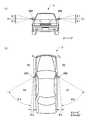
例えば、車両の両側面に設けられたサイドターンランプ(方向指示器)にあっては、30mの距離から昼間において点灯を確認できるものであり、かつ、その照射光が他の交通を妨げないものであることとされている。即ち、図9の(a)に示されるように、サイドターンランプ200の中心を通り、車両の進行方向に直交する水平線O1を含む、水平面より上方15度(θ1)の平面及び下方15度(θ1)の平面、及び図9の(b)に示されるように、サイドターンランプ200の中心を含む車両の進行方向に平行な鉛直面O2であって、サイドターンランプ200の中心より後方にあるものよりサイドターンランプ200の外側方向5度(θ2)の平面と、サイドターンランプ200の更に外側方向55度(θ3)の平面とで囲まれる範囲において、すべての位置から見通すことができるものであるとされている。 For example, in side turn lamps (direction indicators) provided on both sides of a vehicle, lighting can be confirmed in the daytime from a distance of 30 m, and the irradiation light does not interfere with other traffic. It is supposed to be. That is, as shown in FIG. 9A, a
ところで、車両の両側面に設けられたドアミラー装置は路面から程よい高さにあるため、対向車や歩行者などの他の交通からも見易い。この高い視認性の利点に着目して、車両が右左折又は進路の変更をするときに発光する機能を取り付けたドアミラー装置が知られており、本出願人もサイドターンランプの出願を行っている(特許文献1を参照)。 By the way, since the door mirror device provided on both sides of the vehicle is at a moderate height from the road surface, it is easy to see from other traffic such as oncoming vehicles and pedestrians. Focusing on the advantage of this high visibility, there is known a door mirror device with a function of emitting light when the vehicle turns right or left or changes the course, and the applicant has also filed a side turn lamp. (See Patent Document 1).
上述したように、サイドターンランプは、車両の前後方向に対して斜め後方に形成される法規領域(第1領域R1)に、所定の光量で照射する必要がある。近時、他の交通の視認性の向上及び車両のデザイン性の向上の観点から、サイドターンランプ200の前方部分(法規領域以外の部分で、図9の(b)に示される第2領域R2)を発光させたいという要請が生じている(例えば、特許文献2を参照)。 As described above, the side turn lamp needs to irradiate the legal region (first region R1) formed obliquely rearward with respect to the front-rear direction of the vehicle with a predetermined amount of light. Recently, from the viewpoint of improving the visibility of other traffic and improving the design of the vehicle, the front portion of the side turn lamp 200 (the second region R2 shown in FIG. 9B in a portion other than the legal region). ) Is desired to emit light (see, for example, Patent Document 2).
特許文献2に開示された技術では、サイドターンランプのハウジングの全体に亘って導光体(光ファイバ)を配し、車両のボディ側に設けられた発光体から照射される光を導光体の端面部に入射させる。これによって導光体の全体から、法規領域(第1領域R1)とそれ以外の前方領域(第2領域R2)に光を照射している。 In the technique disclosed in
上記した技術では、射出成形で所定の形状に加工(型成形)した導光体を使用している。このため、導光体の汎用性が低く、同一形状の導光体を他の車両に流用することは困難である。また、導光体を所定の形状に加工するために成形型(金型)を必要とし、高価である。 In the above-described technology, a light guide processed (molded) into a predetermined shape by injection molding is used. For this reason, the versatility of the light guide is low, and it is difficult to divert the light guide having the same shape to other vehicles. In addition, a molding die (mold) is required to process the light guide into a predetermined shape, which is expensive.
本発明は上記した事情に鑑みてなされたものであり、車両用灯具に使用される導光体を、安価に提供することを課題としている。 This invention is made | formed in view of an above-described situation, and makes it a subject to provide the light guide used for a vehicle lamp at low cost.
上記課題を解決するための本発明は、
車両用灯具に使用され、発光体から照射された光が外周面部から出射することによって少なくともその外周面部が発光する導光体であって、
全長に亘って外径が一定の棒形状で光を透過可能な材質よりなり、
その外周面部が粗面とされ、
軸方向の一端部から入射した光を前記粗面とされた外周面部で乱反射させ、その外周面部から出射させることにより、少なくとも外周面部が発光することを特徴としている。The present invention for solving the above problems is as follows.
A light guide that is used in a vehicle lamp and emits light emitted from a light emitter from an outer peripheral surface portion so that at least the outer peripheral surface portion emits light,
Made of a material that can transmit light in a rod shape with a constant outer diameter over its entire length,
The outer peripheral surface portion is a rough surface,
At least the outer peripheral surface portion emits light by irregularly reflecting the light incident from one end portion in the axial direction on the rough outer peripheral surface portion and emitting the light from the outer peripheral surface portion.
本発明に係る導光体は、上記したように構成されていて、全長に亘って外径が一定の棒形状である。そして、その外周面部が粗面とされている。軸方向の一端部から入射した光は、外周面部で乱反射することにより、外周面部から出射する。これにより外周面部が発光する。本発明に係る導光体は単純な棒形状であり、従来技術のような複雑形状となっていないため、成形型等を必要とせず安価である。そして、長さを変えるだけで、各種の大きさの車両用灯具に使用することができる。 The light guide according to the present invention is configured as described above, and has a rod shape with a constant outer diameter over the entire length. And the outer peripheral surface part is made into the rough surface. The light incident from one end in the axial direction is emitted from the outer peripheral surface portion by irregular reflection at the outer peripheral surface portion. As a result, the outer peripheral surface emits light. Since the light guide according to the present invention has a simple rod shape and is not a complicated shape as in the prior art, it does not require a mold or the like and is inexpensive. And it can use for the vehicle lamp of various magnitude | sizes only by changing length.
前記粗面とされた導光体本体部の外周面部に被覆部をコーティングすることができる。これにより、導光体本体部の軸方向の一端部から臨界角以上の入射角で入射した光を、前記粗面とされた外周面部と前記被覆部との間で全反射させて、軸方向の他端部から出射させることができる。 A coating portion can be coated on the outer peripheral surface portion of the light guide body portion having the rough surface. Thereby, light incident at an incident angle greater than the critical angle from one axial end portion of the light guide body portion is totally reflected between the rough outer peripheral surface portion and the covering portion, and the axial direction Can be emitted from the other end.
更に、被覆部の外周面部を平滑面とすることが望ましい。これにより、導光体を外側から視認したときに、粗面となっている外周面部が目立たなくなり、車両用灯具の見栄えが良好になる。 Furthermore, it is desirable that the outer peripheral surface portion of the covering portion be a smooth surface. Thereby, when visually recognizing the light guide from the outside, the outer peripheral surface portion which is a rough surface becomes inconspicuous, and the appearance of the vehicular lamp is improved.
前記導光体本体部及び/又は前記被覆部を、着色透明としてもよい。これにより、車両用灯具の外観を各種の色彩で実現することができ、車両用灯具の装飾性をより向上させることができる。 The light guide body part and / or the covering part may be colored and transparent. Thereby, the appearance of the vehicular lamp can be realized in various colors, and the decorativeness of the vehicular lamp can be further improved.
また、上記課題を解決するための本発明は、
車両用灯具に使用され、発光体から照射された光が外周面部から出射することによって少なくともその外周面部が発光する導光体であって、
全長に亘って外径が一定の棒形状で光を透過可能な材質よりなり、
その外周面部に光を散乱する散乱材が添加され、
軸方向の一端部から入射した光を前記散乱材に衝突させてその外周面部から出射させることにより、少なくとも外周面部が発光することを特徴としている。The present invention for solving the above problems
A light guide that is used in a vehicle lamp and emits light emitted from a light emitter from an outer peripheral surface portion so that at least the outer peripheral surface portion emits light,
Made of a material that can transmit light in a rod shape with a constant outer diameter over its entire length,
A scattering material that scatters light is added to the outer peripheral surface portion,
At least the outer peripheral surface portion emits light by colliding light incident from one end portion in the axial direction with the scattering material and emitting it from the outer peripheral surface portion.
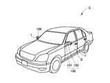
以下、本発明の実施の形態について、詳細に説明する。本明細書では、主として自動車Cのドアミラー装置100に取り付けられるサイドターンランプ1(車両用灯具)に使用される導光体について例示しているが、本発明はこれらに限定されるものではなく、特許請求の範囲の趣旨を逸脱しない限りにおいて、当業者の知識に基づく種々の変更が可能である。 Hereinafter, embodiments of the present invention will be described in detail. In this specification, the light guide used mainly for the side turn lamp 1 (vehicle lamp) attached to the
本発明において、図1は自動車Cの斜視図、図2はミラー本体部102の正面図、図3は第1実施例のサイドターンランプ1をミラー本体部102のハウジング2に取り付ける状態を示す図、図4はサイドターンランプ1の分解斜視図、図5は同じく断面図である。 In the present invention, FIG. 1 is a perspective view of an automobile C, FIG. 2 is a front view of a mirror
図1ないし図3に示されるように、車両用のドアミラー装置100は、自動車Cの両側に設けられたドアDにそれぞれ装着されている。ドアミラー装置100は、ドアDに取り付けられるミラーベース部101と、そのミラーベース部101に支持されるミラー本体部102とを備えている。ミラー本体部102は、自動車Cの後方に向けて取り付けられ、運転者又は搭乗者が後方を確認するためのミラー(図示せず)と、このミラーを保持するミラーホルダ(図示せず)と、ミラーの角度調整を行なうアクチュエータ(図示せず)と、方向指示器などの役割を担うサイドターンランプ1(車両用灯具の一例である。)と、それらの収納及び保護を図るハウジング2と、アクチュエータの取り付けられるフレームの役目を果たすものであって、これらミラー、アクチュエータ、及びサイドターンランプ1をハウジング2に連結する役目を担う取付け基盤(図示せず)と、その取付け基盤の一方の端部に取り付けられて、ミラー本体部102を、ミラーベース部101に対する使用状態と格納状態との間の位置で回転駆動させる電動格納装置103とを含み構成される。なお、ハウジング2は、その全体がベッセル形状(すり鉢状の容器形状)を呈するものであり、例えばプラスチック材にて一体的に成形することができ、予め定められた場所に窓部3(灯具取付部)が形成されている。この窓部3に対応してサイドターンランプ1が外部に露出するように装着され、この状態でサイドターンランプ1の発光体(後述)が点滅、点灯等することにより方向指示器等として機能し、他の交通に右左折又は進路変更などを示すこととなる。 As shown in FIGS. 1 to 3, the vehicle
本発明の第1実施例の導光体が取り付けられたサイドターンランプ1について説明する。このサイドターンランプ1は、第1発光体の光が直接的に法規領域(第1領域R1)を照射するとともに、第2発光体の光が導光体に入射し、その外周面部から出射された光が車両の前方領域を照射する形態である。図4及び図5に示されるように、サイドターンランプ1は、帯状形態をなすフレキシブル基板4と、そのフレキシブル基板4を取り付けて保持するベース部材5と、ベース部材5に取り付けられたフレキシブル基板4を覆う形で該フレキシブル基板4を収納するリフレクタ6と、リフレクタ6に収容される導光体(第1実施例の導光体7)と、リフレクタ6を覆うレンズ部8とを備えている。 The
図4に示されるように、フレキシブル基板4を構成する薄い帯状で、折曲げ可能な基板本体9の一方側の面には、計4個の発光体(LED11,12,13,14)が取り付けられている。この基板本体9は、例えばポリイミド、ポリエステルなどをベースフィルムとした屈曲性に優れた銅張板よりなる。また、各LED1〜14は、表面実装型LEDである。基板本体9の一端部(後端部)から、各LED11〜14に電源を供給する2本のリード線15が延設されている。2本のリード線15は、コネクタ16に挿通されている。フレキシブル基板4の基板本体9の他端部(前端部。即ち、各リード線15が延設されていない側)にバックプレート17が固着され、このバックプレート17の部分に2個のLED11,12(発光体)が並んで取り付けられている。また、基板本体9の長手方向のほぼ中央部にバックプレート18が固着され、このバックプレート18の部分にLED13(発光体)が取り付けられている。更に、基板本体9の後端部にバックプレート19が固着され、このバックプレート19の部分にLED14(発光体)が取り付けられている。上記した4個のLED11〜14のうち、LED11〜13は、自動車Cの前後方向に対して斜め後方に形成される第1領域R1(法規領域。図9の(b)参照)に向かって光を照射するためのものであり、LED14は、自動車Cの前後方向に対してドアミラー装置100の前方に形成される第2領域R2(図9の(b)参照)に向かって光を照射し、サイドターンランプ1の装飾性を高めるためのものである。 As shown in FIG. 4, a total of four light emitters (
次に、ベース部材5について説明する。図4及び図5に示されるように、ベース部材5は、ABS樹脂やASA樹脂等の熱可塑性樹脂で形成され、ドアミラー装置100を構成するハウジング2(図2参照)の形状に倣って、長手方向に湾曲した形状をなす。そして、ベース部材5のほぼ全領域に亘ってフレキシブル基板4を収納する収納凹部21が形成されている。収納凹部21には、3つの取付部22,23,24が、ベース部材5の長手方向に所定の間隔をおいて、収納凹部21の底面部から隆起する形で設けられている。これらの取付部22〜24に、フレキシブル基板4の各バックプレート17〜19が差し込まれる。これにより、フレキシブル基板4が、ベース部材5に対してずれないように保持される。 Next, the
ベース部材5における収納凹部21の後端部には、フレキシブル基板4のリード線15を通し、コネクタ16を取り付けるための貫通孔25が設けられている。また、ベース部材5における収納凹部21の内壁面部には、リフレクタ6の係止爪26(後述)を係止する係止孔27が設けられている。更に、ベース部材5の外壁面部には、ベース部材5をハウジング2にねじ固定するねじ(図示せず)を通すための通し孔が設けられたブラケット28,29が設けられている。 A through
次に、リフレクタ6について説明する。リフレクタ6は、金属、樹脂、セラミック等よりなる。そして、サイドターンランプ1の装飾性を考慮して、例えば蒸着、光沢塗装又はメッキ等を施した樹脂材料や、鏡面仕上げを施したアルミニウム等の金属材料とすることができる。図4及び図5に示されるように、リフレクタ6は、ベース部材5の湾曲状態に対応して長手方向に湾曲されている。リフレクタ6の両外壁面部には、弾性変形可能な係止爪26が設けられている。リフレクタ6は、係止爪26が、対応するベース部材5の係止孔27に係止されることにより固定される。リフレクタ6においてフレキシブル基板4のLED11,12,13と対応する位置には、それらを外部(第1領域R1)に露出させるための開口部31,32が設けられている。 Next, the
また、リフレクタ6の表面部で、前述した第2領域R2に対応する部分には、棒状の導光体7を取り付けるための凹部33が設けられている。凹部33において、長手方向に対向配置される一対の側壁部には、導光体7の軸方向の両端部を差し込んで支持するための差込み孔34,35が設けられている(図5参照)。 In addition, a
リフレクタ6は、フレキシブル基板4が取り付けられたベース部材5の収納凹部21を覆うようにして取り付けられる。そして、ベース部材5の収納凹部21の内壁面部に当接して弾性変形したリフレクタ6の係止爪26が、対応するベース部材5の係止孔27に入って弾性復元する。これにより、リフレクタ6の抜止めが図られる。このとき、フレキシブル基板4に取り付けられたLED11,12は、リフレクタ6の開口部31の部分に配置され、LED13はリフレクタ6の開口部32の部分に配置される。これにより、各LED11〜13から照射された光が、それぞれに対応する開口部31,32を通って外部(第1領域R1)に照射される。 The
次に、レンズ部8について説明する。図4及び図5に示されるように、リフレクタ6にレンズ部8が取り付けられる。レンズ部8は、例えば、ポリメタクリル酸メチル(PMMA)、ポリカーボネート(PC)、ポリプロピレン(PP)、ABS樹脂等の透明又は半透明の熱可塑性樹脂で形成され、ドアミラー装置100のハウジング2の形状に倣って湾曲した形状をなす。レンズ部8の裏面側でLED11,12と対向する部分には、多数の鋸刃状の突条を有するレンズカット部36が設けられている。LED11,12から照射された光は、レンズ部8のレンズカット部36で屈折し、クリアな光となって第1領域R1に照射される。レンズ部8により、リフレクタ6の開口部31,32が覆われ、露出状態の各LED11〜13が保護されるとともに、サイドターンランプ1の装飾性が向上する。 Next, the
次に、サイドターンランプ1に使用される第1実施例の導光体7について説明する。図4及び図5に示されるように、本実施例の導光体7は、全長に亘って一定の外径(6〜10mm)を有する棒形状で、光を透過可能な材質(例えば、アクリル、ポリカーボネート等の樹脂材)よりなる。そして、軸方向に可撓性を有する。導光体7は、ハウジング2の湾曲形状に倣って湾曲してリフレクタ6に取り付けられるとともに、取付け状態でリフレクタ6の凹部33の底面部からほぼ等距離だけ離れて配置される。このとき、導光体7の軸方向の両端面部7a,7bがリフレクタの差込み孔34,35に挿入されて保持される。導光体7の一方側の端面部7a(リフレクタ6の差込み孔34に挿入される側の端面部)は、リフレクタ6に取り付けられた状態でLED14と対向配置されるように斜めに切断されている。また、導光体7の他方側の端面部7b(リフレクタ6の差込み孔35に挿入される側の端面部)は軸方向に対してほぼ直角に切断されていて、取付け状態で取付部23に近接して配置されている。 Next, the
図6に示されるように、導光体7の外周面部は粗面となっていて、当該部分に凹凸部37が設けられている。軸方向の一方側の端面部7a(LED14と対向する端面部)から導光体7に入射した光Laは、外周面部の凹凸部37で乱反射することにより、外周面部から光Lbとなって出射する。導光体7の外周面部を粗面とするためには、外周面部に表面処理(例えば、ショットブラスト)、凹凸面の転写、切削等を施す。 As shown in FIG. 6, the outer peripheral surface portion of the
第1実施例の導光体7が取り付けられたサイドターンランプ1の作用について説明する。図5に示されるように、車両の運転者がサイドターンランプ1のスイッチ(図示せず)を操作すると、各LED11〜14が発光する。LED11,12及びLED13は、車両の前後方向に対して所定角度で斜め後方に形成される第1領域R1に光H1を照射する。 The operation of the
また、図5及び図6に示されるように、LED14は、導光体7の一方側の端面部7aに光Laを照射する。導光体7に入射した光Laは、外周面部に設けられた凹凸部37によって乱反射し、外周面部から光Lbとなって出射する。これにより、自動車Cの前方領域(自動車Cの前後方向に対してドアミラー装置100の前方に形成される第2領域R2)に光H2が照射され、他の交通からの視認性が良好になるとともに、サイドターンランプ1の装飾性が向上する。 Moreover, as FIG.5 and FIG.6 shows, LED14 irradiates light La to the
導光体7の外周面部から、リフレクタ6の側に向かう光はリフレクタ6で反射し、光H2となって第2領域R2を照射する。これにより、第2領域R2を照射する光H2の光量が増大する。 Light traveling from the outer peripheral surface portion of the
次に、第2実施例の導光体41について説明する。図6の(b)に示されるように、外周面部に透明な塗料を塗布することにより、被覆部42を設けてもよい。これにより、導光体7の外周面部の凹凸部37が目立たなくなって、サイドターンランプ1の見栄えが良好になる。 Next, the
また、塗料にフッ素が含まれている場合、フッ素は屈折率を低下させるという機能を有するので、導光体7の外周面部と被覆部42との間で、臨界角以上の入射角で入射した光Lcを全反射させ、導光体7の他方側の端面部7bから出射させることができる。これにより、発光体(LED)から照射された光を、導光体7の外周面部からだけでなく、端面部7bからも出射できるようになる。 In addition, when the paint contains fluorine, the fluorine has a function of lowering the refractive index, so that it is incident between the outer peripheral surface portion of the
第2実施例の導光体41を使用したサイドターンランプ43を、図7に示す。このサイドターンランプ43では、導光体41の軸方向の一方側の端面部41aに入射させた光(図6の(b)における光La,Lc)を、導光体の他方側の端面部7bと外周面部から、それぞれ光H1及び光H2として出射させることができる。このため、発光体(LED)が1つで済むという利点がある。 A
次に、第3実施例の導光体44について説明する。図8に示されるように、導光体45の外周面部には、導光体44の軸方向の一方側の端面部44aから入射した光Laを散乱させるための散乱材45が添加されている。この散乱材45として、例えば酸化アルミニウムや二酸化ケイ素等の金属酸化物粒子、ガラス微粉末等の無機化合物粒子が挙げられる。また、散乱材45の外径は、10〜100μmであることが望ましい。導光体44の一方側の端面部44aから入射した光Laは、散乱材45に当たって乱反射し、光Lbとなって導光体44の外周面部から出射する。これにより、導光体44の外周面部が発光する。 Next, the
上記した各実施例の導光体7,41,44と被覆部42との少なくとも一方に彩色を施して、着色透明としてもよい。これにより、導光体7,41,44から各種の色調の光H1,H2が照射されるため、更にサイドターンランプ1の見栄えを良好にすることができる。 Coloring may be performed by coloring at least one of the light guides 7, 41, 44 and the covering
本発明に係る導光体は、車両用灯具(例えば、自動車のサイドターンランプ)に好適に使用することができる。 The light guide according to the present invention can be suitably used for a vehicular lamp (for example, a side turn lamp of an automobile).
1,43 サイドターンランプ(車両用灯具)
7,41,44 導光体
11,12,13,14 LED(発光体)
37 凹凸部(粗面)
42 被覆部(コーティング)
45 散乱材
La,Lb,Lc 光1,43 Side turn lamp (vehicle lamp)
7, 41, 44
37 Concavity and convexity (rough surface)
42 Coating (Coating)
45 Scattering material La, Lb, Lc Light
Claims (3)
Translated fromJapanese全長に亘って外径が一定の棒形状で光を透過可能な材質よりなり、
その外周面部が粗面とされ、
軸方向の一端部から入射した光を前記粗面とされた外周面部で乱反射させ、その外周面部から出射させることにより、少なくとも外周面部が発光することを特徴とする車両用灯具に使用される導光体。A light guide that is used in a vehicle lamp and emits light emitted from a light emitter from an outer peripheral surface portion so that at least the outer peripheral surface portion emits light,
Made of a material that can transmit light in a rod shape with a constant outer diameter over its entire length,
The outer peripheral surface portion is a rough surface,
Light introduced from one end portion in the axial direction is diffusely reflected by the outer peripheral surface portion having the rough surface, and emitted from the outer peripheral surface portion, whereby at least the outer peripheral surface portion emits light. Light body.
前記導光体本体部の軸方向の一端部から臨界角以上の入射角で入射した光を、前記粗面とされた外周面部と前記被覆部との間で全反射させて、軸方向の他端部から出射させることを可能にしたことを特徴とする請求項1に記載の車両用灯具に使用される導光体。A coating portion is coated on the outer peripheral surface portion of the light guide body portion which is the rough surface,
Light incident at an incident angle greater than a critical angle from one end of the light guide body in the axial direction is totally reflected between the rough outer peripheral surface and the covering, and the other in the axial direction. The light guide used in the vehicular lamp according to claim 1, wherein the light guide can be emitted from an end portion.
Priority Applications (1)
| Application Number | Priority Date | Filing Date | Title |
|---|---|---|---|
| JP2009193310AJP2011044394A (en) | 2009-08-24 | 2009-08-24 | Light guide body used for lighting fixture for vehicle |
Applications Claiming Priority (1)
| Application Number | Priority Date | Filing Date | Title |
|---|---|---|---|
| JP2009193310AJP2011044394A (en) | 2009-08-24 | 2009-08-24 | Light guide body used for lighting fixture for vehicle |
Publications (1)
| Publication Number | Publication Date |
|---|---|
| JP2011044394Atrue JP2011044394A (en) | 2011-03-03 |
Family
ID=43831653
Family Applications (1)
| Application Number | Title | Priority Date | Filing Date |
|---|---|---|---|
| JP2009193310APendingJP2011044394A (en) | 2009-08-24 | 2009-08-24 | Light guide body used for lighting fixture for vehicle |
Country Status (1)
| Country | Link |
|---|---|
| JP (1) | JP2011044394A (en) |
Cited By (8)
| Publication number | Priority date | Publication date | Assignee | Title |
|---|---|---|---|---|
| JP2012256448A (en)* | 2011-06-07 | 2012-12-27 | Koito Mfg Co Ltd | Vehicle lighting |
| JP2013134857A (en)* | 2011-12-26 | 2013-07-08 | Koito Mfg Co Ltd | Vehicle lighting fixture |
| JP2013171795A (en)* | 2012-02-22 | 2013-09-02 | Stanley Electric Co Ltd | Vehicle lamp |
| JPWO2012133147A1 (en)* | 2011-03-30 | 2014-07-28 | 株式会社ミツバ | Turn lamp for door mirror |
| JP2015204232A (en)* | 2014-04-15 | 2015-11-16 | 市光工業株式会社 | Vehicle lamp fitting |
| JP2017228464A (en)* | 2016-06-23 | 2017-12-28 | 市光工業株式会社 | VEHICLE LIGHT, VEHICLE RIGHT VISUAL DEVICE PROVIDED WITH VEHICLE LIGHT |
| WO2018074242A1 (en)* | 2016-10-17 | 2018-04-26 | 株式会社小糸製作所 | Vehicle lamp fitting |
| WO2024094692A1 (en)* | 2022-11-01 | 2024-05-10 | Motherson Innovations Company Limited | Lighting device for rear-view device of vehicle |
Citations (5)
| Publication number | Priority date | Publication date | Assignee | Title |
|---|---|---|---|---|
| JPH07179148A (en)* | 1993-12-24 | 1995-07-18 | Bridgestone Corp | Lighting device for vehicle |
| JP2000292786A (en)* | 1999-04-05 | 2000-10-20 | Hitachi Ltd | Linear light source and liquid crystal display device using the linear light source |
| JP2003151333A (en)* | 2001-11-09 | 2003-05-23 | Fujitsu Kasei Kk | Surface lighting device and liquid crystal display device |
| JP2005228510A (en)* | 2004-02-10 | 2005-08-25 | Ichikoh Ind Ltd | Vehicle lighting |
| JP2007250290A (en)* | 2006-03-15 | 2007-09-27 | Koito Mfg Co Ltd | Side turn signal lamp |
- 2009
- 2009-08-24JPJP2009193310Apatent/JP2011044394A/enactivePending
Patent Citations (5)
| Publication number | Priority date | Publication date | Assignee | Title |
|---|---|---|---|---|
| JPH07179148A (en)* | 1993-12-24 | 1995-07-18 | Bridgestone Corp | Lighting device for vehicle |
| JP2000292786A (en)* | 1999-04-05 | 2000-10-20 | Hitachi Ltd | Linear light source and liquid crystal display device using the linear light source |
| JP2003151333A (en)* | 2001-11-09 | 2003-05-23 | Fujitsu Kasei Kk | Surface lighting device and liquid crystal display device |
| JP2005228510A (en)* | 2004-02-10 | 2005-08-25 | Ichikoh Ind Ltd | Vehicle lighting |
| JP2007250290A (en)* | 2006-03-15 | 2007-09-27 | Koito Mfg Co Ltd | Side turn signal lamp |
Cited By (11)
| Publication number | Priority date | Publication date | Assignee | Title |
|---|---|---|---|---|
| JPWO2012133147A1 (en)* | 2011-03-30 | 2014-07-28 | 株式会社ミツバ | Turn lamp for door mirror |
| JP2012256448A (en)* | 2011-06-07 | 2012-12-27 | Koito Mfg Co Ltd | Vehicle lighting |
| JP2013134857A (en)* | 2011-12-26 | 2013-07-08 | Koito Mfg Co Ltd | Vehicle lighting fixture |
| JP2013171795A (en)* | 2012-02-22 | 2013-09-02 | Stanley Electric Co Ltd | Vehicle lamp |
| JP2015204232A (en)* | 2014-04-15 | 2015-11-16 | 市光工業株式会社 | Vehicle lamp fitting |
| JP2017228464A (en)* | 2016-06-23 | 2017-12-28 | 市光工業株式会社 | VEHICLE LIGHT, VEHICLE RIGHT VISUAL DEVICE PROVIDED WITH VEHICLE LIGHT |
| WO2018074242A1 (en)* | 2016-10-17 | 2018-04-26 | 株式会社小糸製作所 | Vehicle lamp fitting |
| JPWO2018074242A1 (en)* | 2016-10-17 | 2019-09-05 | 株式会社小糸製作所 | Vehicle lighting |
| US11015779B2 (en) | 2016-10-17 | 2021-05-25 | Koito Manufacturing Co., Ltd. | Vehicle lamp with light guide having rod-shaped part and plate-shaped part |
| JP6998314B2 (en) | 2016-10-17 | 2022-02-04 | 株式会社小糸製作所 | Vehicle lighting |
| WO2024094692A1 (en)* | 2022-11-01 | 2024-05-10 | Motherson Innovations Company Limited | Lighting device for rear-view device of vehicle |
Similar Documents
| Publication | Publication Date | Title |
|---|---|---|
| US11054105B2 (en) | Lamp and vehicle having same | |
| JP2011044394A (en) | Light guide body used for lighting fixture for vehicle | |
| KR101232391B1 (en) | exterior rearview assembly | |
| US8469563B2 (en) | Turn-indicator light module for a vehicle mirror assembly and vehicle mirror assembly comprising a turn-indicator light module | |
| JP5945238B2 (en) | Vehicle lamp and vehicle rear panel | |
| US7357549B2 (en) | Vehicle lamp | |
| US10760763B2 (en) | Lighting module in particular for a high-mounted stop light of smooth appearance | |
| JP5852114B2 (en) | Automotive signal lamp | |
| JP5282133B2 (en) | Vehicle lighting device | |
| JP4798784B2 (en) | Vehicle lighting | |
| JP4806715B2 (en) | Vehicle lighting | |
| US8845156B2 (en) | Vehicle lamp | |
| JP5366707B2 (en) | Vehicle lighting | |
| CN103574407A (en) | Linear lighting device | |
| KR102266373B1 (en) | Lighting and/or signalling system with light guides for a vehicle | |
| CN109312905A (en) | Car lighting unit with light guide plate | |
| EP3463980B1 (en) | A lamp assembly for a vehicle | |
| KR101232302B1 (en) | Lamp for a Motor vehicle | |
| KR20160102131A (en) | Motor vehicle lighting device | |
| JP5366708B2 (en) | Vehicle lighting | |
| CN112902100A (en) | Light bar for external lighting assembly | |
| JP2008174083A (en) | VEHICLE LIGHT, VEHICLE OUTSIDE Mirror DEVICE PROVIDED WITH VEHICLE LIGHT | |
| JP4666174B2 (en) | Vehicle lighting | |
| JP4866444B2 (en) | Mounting structure of light guide in vehicle lamp | |
| JP4565654B2 (en) | Lamp |
Legal Events
| Date | Code | Title | Description |
|---|---|---|---|
| A621 | Written request for application examination | Free format text:JAPANESE INTERMEDIATE CODE: A621 Effective date:20120705 | |
| RD02 | Notification of acceptance of power of attorney | Free format text:JAPANESE INTERMEDIATE CODE: A7422 Effective date:20121017 | |
| A977 | Report on retrieval | Free format text:JAPANESE INTERMEDIATE CODE: A971007 Effective date:20130731 | |
| A131 | Notification of reasons for refusal | Free format text:JAPANESE INTERMEDIATE CODE: A131 Effective date:20130806 | |
| A521 | Written amendment | Free format text:JAPANESE INTERMEDIATE CODE: A523 Effective date:20130924 | |
| A977 | Report on retrieval | Free format text:JAPANESE INTERMEDIATE CODE: A971007 Effective date:20130926 | |
| A02 | Decision of refusal | Free format text:JAPANESE INTERMEDIATE CODE: A02 Effective date:20140106 |