JP2011037308A - Vehicular occupant protection system - Google Patents
Vehicular occupant protection systemDownload PDFInfo
- Publication number
- JP2011037308A JP2011037308AJP2009183702AJP2009183702AJP2011037308AJP 2011037308 AJP2011037308 AJP 2011037308AJP 2009183702 AJP2009183702 AJP 2009183702AJP 2009183702 AJP2009183702 AJP 2009183702AJP 2011037308 AJP2011037308 AJP 2011037308A
- Authority
- JP
- Japan
- Prior art keywords
- collision
- vehicle
- occupant
- possibility
- host vehicle
- Prior art date
- Legal status (The legal status is an assumption and is not a legal conclusion. Google has not performed a legal analysis and makes no representation as to the accuracy of the status listed.)
- Pending
Links
Images


Classifications
- G—PHYSICS
- G08—SIGNALLING
- G08G—TRAFFIC CONTROL SYSTEMS
- G08G1/00—Traffic control systems for road vehicles
- G08G1/16—Anti-collision systems
- G08G1/161—Decentralised systems, e.g. inter-vehicle communication
- B—PERFORMING OPERATIONS; TRANSPORTING
- B60—VEHICLES IN GENERAL
- B60R—VEHICLES, VEHICLE FITTINGS, OR VEHICLE PARTS, NOT OTHERWISE PROVIDED FOR
- B60R21/00—Arrangements or fittings on vehicles for protecting or preventing injuries to occupants or pedestrians in case of accidents or other traffic risks
- B60R21/01—Electrical circuits for triggering passive safety arrangements, e.g. airbags, safety belt tighteners, in case of vehicle accidents or impending vehicle accidents
- B60R21/013—Electrical circuits for triggering passive safety arrangements, e.g. airbags, safety belt tighteners, in case of vehicle accidents or impending vehicle accidents including means for detecting collisions, impending collisions or roll-over
- B60R21/0134—Electrical circuits for triggering passive safety arrangements, e.g. airbags, safety belt tighteners, in case of vehicle accidents or impending vehicle accidents including means for detecting collisions, impending collisions or roll-over responsive to imminent contact with an obstacle, e.g. using radar systems
- G—PHYSICS
- G01—MEASURING; TESTING
- G01S—RADIO DIRECTION-FINDING; RADIO NAVIGATION; DETERMINING DISTANCE OR VELOCITY BY USE OF RADIO WAVES; LOCATING OR PRESENCE-DETECTING BY USE OF THE REFLECTION OR RERADIATION OF RADIO WAVES; ANALOGOUS ARRANGEMENTS USING OTHER WAVES
- G01S13/00—Systems using the reflection or reradiation of radio waves, e.g. radar systems; Analogous systems using reflection or reradiation of waves whose nature or wavelength is irrelevant or unspecified
- G01S13/88—Radar or analogous systems specially adapted for specific applications
- G01S13/93—Radar or analogous systems specially adapted for specific applications for anti-collision purposes
- G01S13/931—Radar or analogous systems specially adapted for specific applications for anti-collision purposes of land vehicles
- G—PHYSICS
- G08—SIGNALLING
- G08G—TRAFFIC CONTROL SYSTEMS
- G08G1/00—Traffic control systems for road vehicles
- G08G1/16—Anti-collision systems
- G08G1/166—Anti-collision systems for active traffic, e.g. moving vehicles, pedestrians, bikes
- G—PHYSICS
- G01—MEASURING; TESTING
- G01S—RADIO DIRECTION-FINDING; RADIO NAVIGATION; DETERMINING DISTANCE OR VELOCITY BY USE OF RADIO WAVES; LOCATING OR PRESENCE-DETECTING BY USE OF THE REFLECTION OR RERADIATION OF RADIO WAVES; ANALOGOUS ARRANGEMENTS USING OTHER WAVES
- G01S13/00—Systems using the reflection or reradiation of radio waves, e.g. radar systems; Analogous systems using reflection or reradiation of waves whose nature or wavelength is irrelevant or unspecified
- G01S13/88—Radar or analogous systems specially adapted for specific applications
- G01S13/93—Radar or analogous systems specially adapted for specific applications for anti-collision purposes
- G01S13/931—Radar or analogous systems specially adapted for specific applications for anti-collision purposes of land vehicles
- G01S2013/9316—Radar or analogous systems specially adapted for specific applications for anti-collision purposes of land vehicles combined with communication equipment with other vehicles or with base stations
- G—PHYSICS
- G01—MEASURING; TESTING
- G01S—RADIO DIRECTION-FINDING; RADIO NAVIGATION; DETERMINING DISTANCE OR VELOCITY BY USE OF RADIO WAVES; LOCATING OR PRESENCE-DETECTING BY USE OF THE REFLECTION OR RERADIATION OF RADIO WAVES; ANALOGOUS ARRANGEMENTS USING OTHER WAVES
- G01S13/00—Systems using the reflection or reradiation of radio waves, e.g. radar systems; Analogous systems using reflection or reradiation of waves whose nature or wavelength is irrelevant or unspecified
- G01S13/88—Radar or analogous systems specially adapted for specific applications
- G01S13/93—Radar or analogous systems specially adapted for specific applications for anti-collision purposes
- G01S13/931—Radar or analogous systems specially adapted for specific applications for anti-collision purposes of land vehicles
- G01S2013/9318—Controlling the steering
- G—PHYSICS
- G01—MEASURING; TESTING
- G01S—RADIO DIRECTION-FINDING; RADIO NAVIGATION; DETERMINING DISTANCE OR VELOCITY BY USE OF RADIO WAVES; LOCATING OR PRESENCE-DETECTING BY USE OF THE REFLECTION OR RERADIATION OF RADIO WAVES; ANALOGOUS ARRANGEMENTS USING OTHER WAVES
- G01S13/00—Systems using the reflection or reradiation of radio waves, e.g. radar systems; Analogous systems using reflection or reradiation of waves whose nature or wavelength is irrelevant or unspecified
- G01S13/88—Radar or analogous systems specially adapted for specific applications
- G01S13/93—Radar or analogous systems specially adapted for specific applications for anti-collision purposes
- G01S13/931—Radar or analogous systems specially adapted for specific applications for anti-collision purposes of land vehicles
- G01S2013/93185—Controlling the brakes
- G—PHYSICS
- G01—MEASURING; TESTING
- G01S—RADIO DIRECTION-FINDING; RADIO NAVIGATION; DETERMINING DISTANCE OR VELOCITY BY USE OF RADIO WAVES; LOCATING OR PRESENCE-DETECTING BY USE OF THE REFLECTION OR RERADIATION OF RADIO WAVES; ANALOGOUS ARRANGEMENTS USING OTHER WAVES
- G01S13/00—Systems using the reflection or reradiation of radio waves, e.g. radar systems; Analogous systems using reflection or reradiation of waves whose nature or wavelength is irrelevant or unspecified
- G01S13/88—Radar or analogous systems specially adapted for specific applications
- G01S13/93—Radar or analogous systems specially adapted for specific applications for anti-collision purposes
- G01S13/931—Radar or analogous systems specially adapted for specific applications for anti-collision purposes of land vehicles
- G01S2013/9319—Controlling the accelerator
- G—PHYSICS
- G01—MEASURING; TESTING
- G01S—RADIO DIRECTION-FINDING; RADIO NAVIGATION; DETERMINING DISTANCE OR VELOCITY BY USE OF RADIO WAVES; LOCATING OR PRESENCE-DETECTING BY USE OF THE REFLECTION OR RERADIATION OF RADIO WAVES; ANALOGOUS ARRANGEMENTS USING OTHER WAVES
- G01S13/00—Systems using the reflection or reradiation of radio waves, e.g. radar systems; Analogous systems using reflection or reradiation of waves whose nature or wavelength is irrelevant or unspecified
- G01S13/88—Radar or analogous systems specially adapted for specific applications
- G01S13/93—Radar or analogous systems specially adapted for specific applications for anti-collision purposes
- G01S13/931—Radar or analogous systems specially adapted for specific applications for anti-collision purposes of land vehicles
- G01S2013/932—Radar or analogous systems specially adapted for specific applications for anti-collision purposes of land vehicles using own vehicle data, e.g. ground speed, steering wheel direction
- G—PHYSICS
- G01—MEASURING; TESTING
- G01S—RADIO DIRECTION-FINDING; RADIO NAVIGATION; DETERMINING DISTANCE OR VELOCITY BY USE OF RADIO WAVES; LOCATING OR PRESENCE-DETECTING BY USE OF THE REFLECTION OR RERADIATION OF RADIO WAVES; ANALOGOUS ARRANGEMENTS USING OTHER WAVES
- G01S13/00—Systems using the reflection or reradiation of radio waves, e.g. radar systems; Analogous systems using reflection or reradiation of waves whose nature or wavelength is irrelevant or unspecified
- G01S13/88—Radar or analogous systems specially adapted for specific applications
- G01S13/93—Radar or analogous systems specially adapted for specific applications for anti-collision purposes
- G01S13/931—Radar or analogous systems specially adapted for specific applications for anti-collision purposes of land vehicles
- G01S2013/9322—Radar or analogous systems specially adapted for specific applications for anti-collision purposes of land vehicles using additional data, e.g. driver condition, road state or weather data
- G—PHYSICS
- G01—MEASURING; TESTING
- G01S—RADIO DIRECTION-FINDING; RADIO NAVIGATION; DETERMINING DISTANCE OR VELOCITY BY USE OF RADIO WAVES; LOCATING OR PRESENCE-DETECTING BY USE OF THE REFLECTION OR RERADIATION OF RADIO WAVES; ANALOGOUS ARRANGEMENTS USING OTHER WAVES
- G01S13/00—Systems using the reflection or reradiation of radio waves, e.g. radar systems; Analogous systems using reflection or reradiation of waves whose nature or wavelength is irrelevant or unspecified
- G01S13/88—Radar or analogous systems specially adapted for specific applications
- G01S13/93—Radar or analogous systems specially adapted for specific applications for anti-collision purposes
- G01S13/931—Radar or analogous systems specially adapted for specific applications for anti-collision purposes of land vehicles
- G01S2013/9324—Alternative operation using ultrasonic waves
- G—PHYSICS
- G01—MEASURING; TESTING
- G01S—RADIO DIRECTION-FINDING; RADIO NAVIGATION; DETERMINING DISTANCE OR VELOCITY BY USE OF RADIO WAVES; LOCATING OR PRESENCE-DETECTING BY USE OF THE REFLECTION OR RERADIATION OF RADIO WAVES; ANALOGOUS ARRANGEMENTS USING OTHER WAVES
- G01S13/00—Systems using the reflection or reradiation of radio waves, e.g. radar systems; Analogous systems using reflection or reradiation of waves whose nature or wavelength is irrelevant or unspecified
- G01S13/88—Radar or analogous systems specially adapted for specific applications
- G01S13/93—Radar or analogous systems specially adapted for specific applications for anti-collision purposes
- G01S13/931—Radar or analogous systems specially adapted for specific applications for anti-collision purposes of land vehicles
- G01S2013/9327—Sensor installation details
- G01S2013/93271—Sensor installation details in the front of the vehicles
- G—PHYSICS
- G01—MEASURING; TESTING
- G01S—RADIO DIRECTION-FINDING; RADIO NAVIGATION; DETERMINING DISTANCE OR VELOCITY BY USE OF RADIO WAVES; LOCATING OR PRESENCE-DETECTING BY USE OF THE REFLECTION OR RERADIATION OF RADIO WAVES; ANALOGOUS ARRANGEMENTS USING OTHER WAVES
- G01S13/00—Systems using the reflection or reradiation of radio waves, e.g. radar systems; Analogous systems using reflection or reradiation of waves whose nature or wavelength is irrelevant or unspecified
- G01S13/88—Radar or analogous systems specially adapted for specific applications
- G01S13/93—Radar or analogous systems specially adapted for specific applications for anti-collision purposes
- G01S13/931—Radar or analogous systems specially adapted for specific applications for anti-collision purposes of land vehicles
- G01S2013/9327—Sensor installation details
- G01S2013/93272—Sensor installation details in the back of the vehicles
Landscapes
- Engineering & Computer Science (AREA)
- Physics & Mathematics (AREA)
- Radar, Positioning & Navigation (AREA)
- Remote Sensing (AREA)
- General Physics & Mathematics (AREA)
- Electromagnetism (AREA)
- Computer Networks & Wireless Communication (AREA)
- Mechanical Engineering (AREA)
- Traffic Control Systems (AREA)
- Automotive Seat Belt Assembly (AREA)
- Air Bags (AREA)
Abstract
Translated fromJapaneseDescription
Translated fromJapanese本発明は、車両の衝突に際して乗員を保護する車両用乗員保護システムに関する。 The present invention relates to a vehicle occupant protection system that protects an occupant in the event of a vehicle collision.
車両用乗員保護システムとして、車両の衝突に際して衝突の発生直後にエアバッグを膨張させるなど、乗員を保護するシステムが提案され、実用化されている。また、車両周辺の状況や車両の挙動などに基づいて衝突が避けられない状況であることを衝突前に判定して、保護装置を早期に作動させるプリクラッシュシステムも提案され、一部実用化されている。例えば、特表2007−500650号公報(特許文献1)には、センサ信号に依存して制御されるアダプティブなシートを有するプリクラッシュシステム(車両用乗員保護システム)の例が開示されている。このシステムは、衝突の際に乗員の体がシートベルトの下に潜り込むサブマリン現象を回避するために、シート前方を上昇させたり、シート後部に凹部を設けたり、ベルトテンショナーによりシートベルトの拘束力を強めたりする。また、シートサイドサポート部材が立ち上げられて乗員の横滑りが回避されたり、クッション入りの装置がヘッドレストからカラーのように展開されて乗員の頭部の揺動が回避されたりする。 As a vehicle occupant protection system, a system for protecting an occupant has been proposed and put into practical use, such as inflating an airbag immediately after the occurrence of a collision in the event of a vehicle collision. In addition, a pre-crash system has been proposed, in which it is determined before a collision that the collision is inevitable based on the situation around the vehicle and the behavior of the vehicle, and the protection device is activated early, and a part of it is put into practical use. ing. For example, Japanese Translation of PCT International Publication No. 2007-500650 (Patent Document 1) discloses an example of a pre-crash system (vehicle occupant protection system) having an adaptive seat that is controlled depending on a sensor signal. In order to avoid the submarine phenomenon where the occupant's body sinks under the seat belt in the event of a collision, this system raises the front of the seat, provides a recess at the rear of the seat, and restrains the seat belt with a belt tensioner. To strengthen. In addition, the seat side support member is raised to avoid a side slip of the occupant, or the cushioned device is deployed like a collar from the headrest to avoid the swaying of the occupant's head.
プリクラッシュシステムにおいては、シートやシートベルトなどをアクチュエータにより駆動する必要があり、できるだけ迅速且つ確実に衝突を検出する必要がある。例えば、自車両が前方及び側方に対して衝突する可能性をいち早く判定するために、ミリ波レーダを複数設けることも提案されている。特開2009−74803号公報(特許文献2)には、物体検知器として、車両の前方を検知するレーダと、車両の左右それぞれの斜め前方を検知するレーダとの3つのレーダを有する例が記載されている。 In the pre-crash system, it is necessary to drive a seat, a seat belt, and the like by an actuator, and it is necessary to detect a collision as quickly and reliably as possible. For example, it has been proposed to provide a plurality of millimeter wave radars in order to quickly determine the possibility that the host vehicle will collide with the front and side. Japanese Unexamined Patent Application Publication No. 2009-74803 (Patent Document 2) describes an example having three radars as an object detector: a radar that detects the front of the vehicle, and a radar that detects the diagonally forward left and right sides of the vehicle. Has been.
また、プリクラッシュシステムにおいてシートやシートベルトなどを駆動するアクチュエータは起動時間を要し、また駆動対象も機械的な作動時間を要するが、これらはできるだけ短縮されることが好ましい。1つの方法として、衝突を検知するのではなく、衝突を予知してプリクラッシュシステムを起動することが考えられる。特開2007−314015号公報(特許文献3)には、さらに衝突発生を予知して衝突形態に応じて乗員の着座姿勢を適正状態に修正可能な乗員保護装置の技術が開示されている。例えば、左側突用カメラ、右側突用カメラ、後突用カメラの複数のカメラが備えられ、カメラからの画像信号が解析処理されて衝突発生が予知される。また、具体的な衝突予知方法については言及されていないが、車車間通信を利用して、他車両から得られる時々刻々の位置情報と車速情報を用いて、他車両との車間距離と衝突形態とを演算して、衝突発生を予知することが記載されている。 In addition, an actuator that drives a seat, a seat belt, or the like in a pre-crash system requires a start-up time, and a drive target also requires a mechanical operation time. These are preferably shortened as much as possible. As one method, it is conceivable to start a pre-crash system by predicting a collision instead of detecting a collision. Japanese Unexamined Patent Application Publication No. 2007-314015 (Patent Document 3) discloses a technology of an occupant protection device that can further predict the occurrence of a collision and correct the seating posture of the occupant to an appropriate state according to the collision mode. For example, a plurality of cameras including a left-side projecting camera, a right-side projecting camera, and a rear-projecting camera are provided, and an image signal from the camera is analyzed and a collision is predicted. Further, although a specific collision prediction method is not mentioned, the inter-vehicle distance and the collision mode with another vehicle are obtained by using the inter-vehicle communication and the position information and the vehicle speed information obtained from other vehicles every moment. And predicting the occurrence of a collision.
衝突を予知して、プリクラッシュシステムを作動させた場合、結果として衝突が発生しなければ、シートやシートベルトなどが無駄に動くこととなる。例えば、頻繁にシートベルトの締め付けが繰り返されたり、運転中にシートの姿勢が変更されたりした場合には、乗員は煩わしさを覚えることになる。また、衝突を予知して警報などを発する場合にも、衝突の可能性を正確に予知し、適切な時期に警報を発しなければ煩わしいものとなる。例えば、早期に警報を発すると、ドライバーが通常の運転により充分に衝突を回避できるようなケースで頻繁に警報が繰り返されることになり、ドライバーは煩わしさを覚える他、警報を信用しなくなる可能性もある。従って、衝突予知の判定は、適正な時期に高い精度でなされることが好ましい。また、プリクラッシュシステムは、衝突の予知の後に高い反応性を有して構成されたり、制御されたりすることが好ましい。しかし、衝突予知の精度の向上やプリクラッシュシステムの反応速度の向上に際しては、アクチュエータや駆動対象の機械的構造を複雑化したり、コストアップしたりする可能性がある。 When the collision is predicted and the pre-crash system is operated, as a result, if the collision does not occur, the seat, the seat belt, and the like move wastefully. For example, when the tightening of the seat belt is frequently repeated or the posture of the seat is changed during driving, the occupant becomes annoyed. In addition, even when a collision is predicted and an alarm is issued, it is troublesome if the possibility of a collision is accurately predicted and an alarm is not issued at an appropriate time. For example, if an alarm is issued early, the alarm is frequently repeated in a case where the driver can sufficiently avoid a collision by normal driving, and the driver may feel annoyed and may not trust the alarm. There is also. Therefore, it is preferable that the collision prediction is determined with high accuracy at an appropriate time. Also, the pre-crash system is preferably configured or controlled with high reactivity after the prediction of a collision. However, when the accuracy of collision prediction is improved and the response speed of the pre-crash system is improved, there is a possibility that the actuator and the mechanical structure to be driven may be complicated or the cost may be increased.
上記課題に鑑みて、早期に衝突が発生する条件や可能性を把握し、過度な予備作動を抑制しつつ、衝突発生の際には迅速に機能して乗員を保護することが可能な車両用乗員保護システムの実現が望まれる。 In view of the above problems, for vehicles capable of grasping the conditions and the possibility of an early collision and suppressing the excessive preliminary operation and functioning quickly to protect the occupant in the event of a collision Realization of an occupant protection system is desired.
上記課題に鑑みた本発明に係る車両用乗員保護システムの特徴構成は、
自車両が目的地へ向かうルート情報を含む自車情報を取得する自車情報取得部と、
他車両と前記自車両との間の車車間通信により受信され、前記他車両の位置情報を含む他車情報を取得する他車情報取得部と、
前記自車情報と前記他車情報とに基づいて、前記自車両と前記他車両との衝突条件を演算する衝突条件演算部と、
前記衝突条件に応じて、前記自車両の衝突に際して乗員の衝突被害を軽減する衝突被害軽減システムの内、前記衝突条件に対応する衝突被害を軽減可能なシステムの作動を準備させる作動準備部と、を備える点にある。In view of the above problems, the characteristic configuration of the vehicle occupant protection system according to the present invention is as follows.
A vehicle information acquisition unit that acquires vehicle information including route information of the vehicle toward the destination;
An other vehicle information acquisition unit which receives other vehicle information including position information of the other vehicle received by inter-vehicle communication between the other vehicle and the own vehicle;
A collision condition calculation unit that calculates a collision condition between the host vehicle and the other vehicle based on the host vehicle information and the other vehicle information;
In accordance with the collision condition, an operation preparation unit for preparing an operation of a system capable of reducing the collision damage corresponding to the collision condition in the collision damage reduction system for reducing the collision damage of the occupant at the time of the collision of the host vehicle, It is in the point provided with.
この特徴構成によれば、自車両の衝突に際して乗員の衝突被害を軽減する衝突被害軽減システムを、より早期から衝突に備えさせることが可能となる。自車両と他車両との衝突条件を演算することにより、衝突の事前検知の精度も向上する。衝突条件の演算に際しては、自車両が目的地に向かうルート情報と、車車間通信によって得られた他車両の位置情報とが用いられる。従って、自車両がこれから通る経路に関係する他車両に絞って衝突条件を演算することができる。また、自車両の経路に対する他車両の関わり方も事前に把握できるので、衝突条件は高い精度で演算される。このため、過度な警戒により無駄に衝突被害軽減システムを作動させることもない。従って、本構成によれば、早期に衝突が発生する条件や可能性を把握し、過度な予備作動を抑制しつつ、衝突発生の際には迅速に機能して乗員を保護することが可能な車両用乗員保護システムが実現できる。 According to this characteristic configuration, it is possible to prepare a collision damage mitigation system for mitigating the collision damage of the occupant in the event of a collision of the host vehicle from an earlier stage. By calculating the collision condition between the host vehicle and the other vehicle, the accuracy of the prior detection of the collision is improved. In calculating the collision condition, route information of the host vehicle toward the destination and position information of other vehicles obtained by inter-vehicle communication are used. Therefore, the collision condition can be calculated by focusing on other vehicles related to the route through which the host vehicle will travel. In addition, since it is possible to grasp in advance how other vehicles relate to the route of the host vehicle, the collision condition is calculated with high accuracy. For this reason, the collision damage mitigation system is not activated unnecessarily due to excessive vigilance. Therefore, according to this configuration, it is possible to grasp the conditions and possibility of an early collision, suppress excessive pre-operation, and function quickly to protect the occupant when a collision occurs. A vehicle occupant protection system can be realized.
また、本発明に係る車両用乗員保護システムにおける前記衝突条件は、前記衝突条件が成立する可能性及び衝突形態を含むと好適である。 In addition, it is preferable that the collision condition in the vehicle occupant protection system according to the present invention includes a possibility that the collision condition is satisfied and a collision mode.
衝突被害軽減システムは、単一の装置(システム)ではなく、前面衝突、側面衝突、後面衝突、オフセット衝突などの衝突形態に応じてそれぞれ適切なものが準備されていることが多い。従って、衝突条件が衝突形態を含んで演算されると、衝突被害軽減システムの内、当該衝突形態に対応する衝突被害を軽減可能なシステムの作動が適切に準備される。また、同時に複数の衝突形態が想定される場合があるので、衝突条件が成立する可能性に応じて優先順位が設定されると、確率の高い衝突形態に対応する衝突被害を軽減可能なシステムの作動が適切に準備される。 In many cases, the collision damage mitigation system is not a single device (system), but appropriate ones are prepared according to collision types such as front collision, side collision, rear collision, and offset collision. Therefore, when the collision condition is calculated including the collision mode, the operation of the system capable of reducing the collision damage corresponding to the collision mode is appropriately prepared in the collision damage reduction system. In addition, since multiple collision modes may be assumed at the same time, if priority is set according to the possibility that the collision condition is satisfied, the system can reduce the collision damage corresponding to the collision mode with high probability. Operation is properly prepared.
また、本発明に係る車両用乗員保護システムの前記衝突被害軽減システムは、前記他車両を検出して衝突の可能性を判定するプリクラッシュ制御システムと、実際の衝突に際して前記乗員の身体を保護する保護システムとを有し、前記作動準備部は、前記プリクラッシュ制御システムに対して、前記他車両を検出する感度を調整させると好適である。 Further, the collision damage reduction system of the vehicle occupant protection system according to the present invention protects the occupant's body during an actual collision, and a pre-crash control system that detects the other vehicle and determines the possibility of a collision. It is preferable that the operation preparation unit adjust the sensitivity of detecting the other vehicle with respect to the pre-crash control system.
衝突の可能性を判定するプリクラッシュ制御システムが他車両を検出する感度が調整されると、衝突の可能性の判定精度が向上し、判定時期が早くなる可能性が高くなる。その結果、保護システム等を作動させて乗員の衝突被害を軽減するための準備時間に余裕が生まれ、乗員保護効果が向上する。 If the pre-crash control system that determines the possibility of collision is adjusted to detect the sensitivity of other vehicles, the determination accuracy of the possibility of collision is improved, and the possibility that the determination time is earlier is increased. As a result, an extra time is created in the preparation time for operating the protection system and the like to reduce the collision damage of the occupant, and the occupant protection effect is improved.
また、本発明に係る車両用乗員保護システムの前記衝突被害軽減システムが、前記他車両を検出して衝突の可能性を判定するプリクラッシュ制御システムと、実際の衝突に際して前記乗員の身体を保護する保護システムとを有する場合、前記作動準備部は、前記保護システムに対して、衝突に際して最速で所定の作動を完了可能な状態まで準備させると好適である。 Further, the collision damage reduction system of the vehicle occupant protection system according to the present invention protects the occupant's body during an actual collision, and a pre-crash control system that detects the other vehicle and determines the possibility of a collision. In the case of having a protection system, it is preferable that the operation preparation unit prepares the protection system to a state where a predetermined operation can be completed at the fastest speed in the event of a collision.
保護システムが、衝突に際して最速で所定の作動を完了可能な状態まで準備されていると、衝突が発生した際に迅速に保護システムが機能(作動)するので乗員の衝突被害が良好に軽減される。 If the protection system is prepared to a state where the predetermined operation can be completed at the fastest speed in the event of a collision, the protection system functions (activates) quickly when a collision occurs, so that the collision damage of the occupant is reduced well. .
また、本発明に係る車両用乗員保護システムの前記衝突被害軽減システムは、衝突発生後に作動する最終作動システムと、衝突発生前であって衝突が不可避であると判定される衝突前第1時刻で作動する第1システムと、前記衝突前第1時刻より前であって衝突の可能性が高いと判定される衝突前第2時刻で作動する第2システムと、前記衝突前第2時刻より前であって衝突の可能性が有ると判定される衝突前第3時刻で作動する第3システムとを有し、第4システムとして機能する前記作動準備部は、前記衝突前第3時刻よりも前に、前記衝突被害軽減システムの作動を準備させると好適である。 The collision damage alleviating system of the vehicle occupant protection system according to the present invention includes a final operating system that operates after the occurrence of the collision, and a first time before the collision that is determined to be inevitable before the collision occurs. A first system that operates, a second system that operates before the first time before the collision and is determined to have a high possibility of a collision, and a second system that operates at the second time before the collision, and before the second time before the collision. And the third system that operates at a third time before the collision that is determined to have a possibility of a collision, and the operation preparation unit that functions as a fourth system is prior to the third time before the collision. It is preferable to prepare the operation of the collision damage mitigation system.
本構成によれば、衝突の可能性が有ると判定される衝突前第3時刻よりも前に、衝突条件が演算され、その衝突条件に応じて作動準備部が衝突被害軽減システムの作動を準備させる。従って、衝突前第3時刻における衝突の可能性の判定自体の精度も向上させることができ、当該判定の時期も早めることが可能となる。また、衝突の可能性が有ると判定された後に作動したり、作動の準備がなされたりするシステムについても衝突前第3時刻よりも前から準備することが可能となるので、乗員の衝突被害が良好に軽減される。つまり、本構成によれば、早期に衝突が発生する条件や可能性を把握し、過度な予備作動を抑制しつつ、衝突発生の際には迅速に機能して乗員を保護することが可能な車両用乗員保護システムを提供することが可能となる。 According to this configuration, the collision condition is calculated before the third time before the collision determined that there is a possibility of the collision, and the operation preparation unit prepares the operation of the collision damage reduction system according to the collision condition. Let Therefore, the accuracy of the determination of the possibility of collision at the third time before the collision can be improved, and the timing of the determination can be advanced. In addition, it is possible to prepare a system that operates after it is determined that there is a possibility of a collision or is prepared for the operation before the third time before the collision. Reduced well. In other words, according to this configuration, it is possible to grasp the conditions and the possibility that a collision will occur early, suppress excessive pre-operation, and function quickly to protect the occupant when a collision occurs. A vehicle occupant protection system can be provided.
以下、本発明の実施形態を図面に基づいて説明する。本発明の車両用乗員保護システムは、衝突などが生じた際にその被害を軽減する衝突安全システム(パッシブセーフティシステム)と、事前に衝突などを予測して被害を軽減するという予防安全システム(アクティブセーフティシステム)とが融合された総合的な安全システムである。ここでは、このように、衝突(クラッシュ)の発生前から衝突発生後までを広く手当てする総合的な安全システムをプリクラッシュセーフティシステムと称する。パッシブセーフティシステムの一例としては、SRS(supplemental restraint system)エアバッグがある。また、アクティブセーフティシステムとしては、衝突に際してシートベルトを引き込んで張力を増強するシートベルトテンショナや、シートの姿勢を変更するアクティブシート(プリクラッシュシート)などがある。 Hereinafter, embodiments of the present invention will be described with reference to the drawings. The vehicle occupant protection system of the present invention includes a collision safety system (passive safety system) that reduces damage when a collision or the like occurs, and a preventive safety system (active active) that predicts a collision or the like and reduces the damage in advance. Safety system) is a comprehensive safety system. Here, in this way, a comprehensive safety system that deals widely before and after the occurrence of a collision (crash) is referred to as a pre-crash safety system. An example of a passive safety system is an SRS (supplemental restraint system) airbag. In addition, as an active safety system, there are a seat belt tensioner that pulls in a seat belt to increase the tension in the event of a collision, and an active seat (pre-crash seat) that changes the posture of the seat.
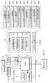
図1は、車両(自車両)80のシステム構成の一例を模式的に示すブロック図である。図1に示すように、本実施形態において車両用乗員保護システム(以下、適否「乗員保護システム」と略称する。)は、プリクラッシュ制御準備システム10と、プリクラッシュ制御システム20と、保護システム30とを有して構成される。厳密に区別されるものではないが、プリクラッシュ制御システム20は、予防安全システム(アクティブセーフティシステム)に相当し、保護システム30は、衝突安全システム(パッシブセーフティシステム)に相当する。また、車両用乗員保護システムは、総合的な安全システム(プリクラッシュセーフティシステム)に相当する。また、プリクラッシュ制御システム20及び保護システム30は、衝突被害軽減システム40に相当する。上述したように、衝突被害軽減システム40は、衝突の発生前から発生後までを広く手当てし、自車両の衝突に際して乗員の衝突被害を軽減するシステムである。車両用乗員保護システムは、衝突被害軽減システム40としてのプリクラッシュ制御システム20及び保護システム30に加え、さらにプリクラッシュ制御準備システム10を備えて構成される。プリクラッシュ制御準備システム10は、衝突被害軽減システム40の有する機能の作動を準備させるシステムである。 FIG. 1 is a block diagram schematically illustrating an example of a system configuration of a vehicle (own vehicle) 80. As shown in FIG. 1, in this embodiment, a vehicle occupant protection system (hereinafter abbreviated as “appropriate“ occupant protection system ”) includes a pre-crash
図2に示すように、プリクラッシュ制御準備システム10は、自車情報取得部11と、他車情報取得部12と、衝突条件演算部13と、作動準備部14との各機能部を有して構成される。自車情報取得部11は、自車両80が目的地へ向かうルート情報を含む自車情報を取得する機能部である。具体的には、自車両80に搭載されるナビゲーションシステム8からルート情報を含むナビゲーション情報を取得する。他車情報取得部12は、他車両と自車両80との間の車車間通信により受信され、当該他車両の位置情報を含む他車情報を取得する機能部である。他車両は、当該他車両が搭載するナビゲーションシステムやGPS(global positioning system)装置などから位置情報を取得する。他車情報取得部12は、自車両80に搭載されるアンテナ6及び車車間通信システム7を介して、この他車両の位置情報を含む他車情報を取得する。 As shown in FIG. 2, the pre-crash
衝突条件演算部13は、自車情報と他車情報とに基づいて、自車両80と他車両との衝突条件を演算する機能部である。この衝突条件は、自車両80を基準とした、前面衝突(前突)、側面衝突(側突)、後面衝突(追突)などの衝突形態を含むと好適である。また、衝突条件は、当該衝突条件が成立する(衝突が発生する)可能性を含むと好適である。さらに、衝突発生時の自車両80の姿勢や速度なども含むと好適である。ここで、姿勢とは、前進走行中、後退中、右左折やカーブなどの旋回中、停車中などである。作動準備部14は、演算された衝突条件に応じて、衝突被害軽減システム40の有する複数のシステムの内、当該衝突条件に対応する衝突被害を軽減可能なシステムの作動を準備させる。つまり、衝突被害軽減システム40は、自車両80の衝突に際して乗員の衝突被害を軽減する種々の機能を有しているが、その内、当該衝突条件に対応した機能の作動が準備される。 The collision condition calculation unit 13 is a functional unit that calculates a collision condition between the
以下、乗員保護システムの構成や制御例について詳述するが、それに先だって自車両90の全体的なシステム構成について説明する。図1に示すように、乗員保護システム(10、20、30、40)は、車内ネットワークであるCAN(controller area network)50を介して、その他の種々のシステムやセンサ類に接続されている。乗員保護システムは、これら多くのシステムやセンサ類と協働して、乗員保護機能を発揮する。 Hereinafter, the configuration and control example of the occupant protection system will be described in detail. Prior to that, the overall system configuration of the
車車間通信システム7は、車両同士が直接情報をやりとりする車車間通信を制御するシステムである。つまり、自車両80と自車両以外の他車両との間で直接、通信を実施し、情報の授受を行うシステムである。車車間通信システム7は、道路脇に設けられた中継器(路側器)を介した車路車間通信を行う機能も有して構成されていてもよい。車車間通信は、例えば、700MHz帯(715M〜725MHz程度)の周波数帯の電波が利用され、この帯域に対応したアンテナ6が車両に搭載される。見通しのよい場所であれば、約270〜300m程度、電波を遮る建物の多い市街地であれば90m程度の範囲内の他車両との間で通信が可能である。尚、道路脇に設けられた路側器と車両との間の通信である路車間通信に利用される5.8GHz帯の電波を用いて車車間通信や車路車間通信を行うことを妨げるものではない。車車間通信システム7は、自車両80と他車両との間で、車両の位置や、速度、進行方向、車両情報(識別情報(ID情報)・サイズ・カテゴリー・年式等)等の情報のやりとりを行う。車両がナビゲーションシステムを搭載しているような場合には、目的地や経路の情報をやりとりしてもよい。 The
ナビゲーションシステム8は、道順案内などを行ないドライバーの運転を支援するシステムである。不図示のGPS装置や、不図示のジャイロなどの自律航法装置などにより、現在位置を特定し、システムに記憶された地図と照らし合わせることでドライバーの運転を支援する。本実施形態においてモニタ装置9は、ナビゲーションシステム8のGUI(graphic user interface)として機能する表示部9aやタッチパネル9bを備えている。上述したように、ナビゲーションシステム8は、プリクラッシュ制御準備システム10と連携する。 The
ブレーキシステム51は、ドライバーにより操作されるブレーキペダルの操作量をブレーキセンサ63により検出して、不図示のアクチュエータを介して車両に制動力を付加してブレーキ力を増強させるブレーキアシストなどを有した電動ブレーキシステムである。例えば、ブレーキのロックを抑制するABS(anti lock braking system)や、コーナリング時の車両の横滑りを抑制する横滑り防止装置(ESC : electronic stability control)、BBW(brake-by-wire)システムも含まれる。ブレーキシステム51は、衝突被害軽減システム40として機能することも可能である。例えば、ドライバーにより操作されるブレーキペダルの操作量に拘わらずブレーキの油圧を高めるブレーキアシストや、自動的にブレーキを掛ける緊急ブレーキとして機能させることもできる。 The brake system 51 includes a brake assist that detects an operation amount of a brake pedal operated by a driver by a
パワーステアリングシステム52は、例えば、ドライバーにより操作されるステアリングホイールの操作量を蛇角センサ66やトルクセンサ67により検出して不図示のアクチュエータによりアシストトルクを付加する電動パワーステアリング(EPS : electric power steering)システムである。駐車支援機能を含む運転支援システム55を備える場合には、ステアリングホイールや操舵輪を不図示のアクチュエータにより駆動することによって自動操舵を行わせることも可能である。 For example, the
エンジン制御システム53は、スロットルセンサ68やアクセルセンサ69などと連携し、燃料噴射量や点火タイミングなどのエンジンの運転制御を行うシステムである。トランスミッション制御システム54は、シフトポジションセンサ61や車輪速センサ62などの各種センサや、エンジン制御システム53などと連携して、最適なトランスミッションの選択と切り換えなどの制御を行うシステムである。その他、カメラ23と連携したモニタシステムや駐車支援システムを含む運転支援システム55、空気圧センサ64やクリアランスソナー65と連携した安全制御システム(不図示)などのシステムも構築される。 The engine control system 53 is a system that controls the operation of the engine such as the fuel injection amount and the ignition timing in cooperation with the
図1に示す各種センサ61〜69は、単一のシステムと連携するものではなく、適宜複数のシステムと連携する。また、各種センサ61〜69は、直接CAN50に接続される場合もあれば、各種システム51〜55などを介して接続される場合もある。例えば、車両の車輪の回転量や単位時間当たりの回転数を検出する車輪速センサ62は、ブレーキシステム51に備えられている場合もある。ブレーキシステム51が、ABSや、横滑り防止装置である場合、CAN50を介すことなく直接、車輪速センサ62の検出結果を受け取れば、迅速に各種制御が実行される。つまり、図1に示すシステムやセンサ、及びこれらの接続形態は一例であり、図示の形態に限定されるものではない。 The
保護システム30には、SRSエアバッグを制御するエアバッグ制御システム31や、シートベルトテンショナを制御するシートベルト制御システム32や、アクティブシートを制御するシート制御システム33などが含まれる。シート制御システム33は、通常時には、乗員がシートの姿勢を調整するためのアクティブシートシステムとして機能する。保護システム30として機能する際には、プリクラッシュシートシステムとして機能する。エアバッグ制御システム31は、エアバッグを展開させるアクチュエータ36などを駆動制御する。シートベルト制御システム32は、シートベルトを引き込むアクチュエータ37などを駆動制御する。シート制御システム33は、シートを動かすアクチュエータ38を駆動制御する。それぞれのシステムが駆動制御するアクチュエータは単一に限らず、複数のアクチュエータが制御されてもよい。また、上記は一例であり、保護システム30として、他の機構が備えられていてもよい。 The
エアバッグ制御システム31は、運転席や助手席に設けられたSRSエアバッグを制御するものに限定されるものではない。側突時に対応するためにドアから展開されてドアへの衝突を抑制するサイドエアバッグや、ドアに沿って天井から展開されて窓やピラーへの衝突を抑制するカーテンエアバッグ、膝への衝撃を抑制するためステアリングやグローブボックスの下から展開されるニーエアバッグ、後部座席の乗員同士の衝突を抑制するために天井から後部座席の中央の乗員間の空間に向かって展開される後席センターエアバッグなどを制御するシステムを有していてもよい。 The
アクティブシート(プリクラッシュシート)の一例としては、図3に示すように、所定角度以上に寝た状態となっているシートバック92を引き起こして、シートベルトによる乗員保護効果が最大限に得られる状態とするものがある。ここでは、プリクラッシュシートバックと称する。つまり、シートバック92を正しい位置へ戻すことで、シートベルトによる乗員の拘束力を高め、衝突時の乗員への衝撃を緩和する。保護システム30として機能するプリクラッシュシートでは、一般的なアクティブシートよりも高速な作動が求められる。例えば、1秒当たり10°でシートバック92が引き起こされる。 As an example of an active seat (pre-crash seat), as shown in FIG. 3, a seat back 92 that is in a state of lying at a predetermined angle or more is caused, and the occupant protection effect by the seat belt is maximized. There is something to do. Here, it is called a pre-crash seat back. That is, by returning the seat back 92 to the correct position, the restraint force of the occupant by the seat belt is increased, and the impact on the occupant at the time of the collision is reduced. The pre-crash sheet functioning as the
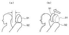
また、アクティブシートの一例として、特に自車両への追突に際して乗員の頭部及び頸部への衝撃を緩和し、むち打ち傷害を軽減するために、図4に示すようにヘッドレスト91の位置を移動させ、乗員の頭部とヘッドレスト91との隙間を詰めるものもある。ここでは、プリクラッシュヘッドレストと称する。ヘッドレスト91の内部に不図示のセンサを内蔵し、このセンサで頭部位置を検出して適切な位置までヘッドレスト91を移動させると好適である。この他、衝突時に乗員が慣性力によってシートベルトの下に潜り込むサブマリン現象を抑制するためにシートクッション93の前方を上昇させてもよい(プリクラッシュシートクッション)。シートクッション93の上昇は、シートクッション93の下にエアバッグを内蔵し、このエアバッグを展開することによって行ってもよい(シートクッションエアバッグ)。また、シートベルトやエアバッグの効果を最大限に引き出すために、シート90の全体を前後にスライドさせてもよい(プリクラッシュシート)。 As an example of the active seat, the
但し、シート90上に乗員が着座していなければアクティブシートの作動は無駄であり、また、乗員の体格などに応じて最適なシート90の姿勢も異なることから、シート制御システム33は、乗員検知センサ41の検出結果を利用すると好適である。乗員検知センサ41は、トーションバー式のものや、圧電センサ式のものが公知である。シートベルト制御システム32やエアバッグ制御システム31も乗員検知センサ41の検出結果を利用して制御を行う。特に、チャイルドシートを用いて子供が乗車している際には、エアバッグを作動させない方が好ましく、乗員検知センサ41の検出結果を利用して乗員判別などが実施されると好適である。また、シートベルト制御システム32は、シートベルトのバックルに設けられた不図示のバックルスイッチの出力に基づいて乗員の有無やシートベルトの使用状態を判定すると好適である。 However, if the occupant is not seated on the
エアバッグ制御システム31をはじめとして、保護システム30の種々のシステムは、その他、バンパ圧力センサ42や、加速度センサ43などの検出結果に基づいて制御を行う。衝突や急制動などによる自車両の急な減速に伴う大きな加速度や、他車両や物体と自車両との衝突によりパンパに加わる圧力などに基づいて衝突などの事象の発生を検出して、その事象に応じた制御を実施する。バンパ圧力センサ42や、加速度センサ43などは、当然ながら、複数搭載されていてもよい。例えば、加速度センサ43は、ドアやピラー、車両中央などに複数配置されていると好適である。複数の加速度センサ43の検出結果は、単独で用いられても良いし、複数の結果を加味して用いられても良いし、他のセンサやレーダなどの検出結果と共に用いられてもよい。 In addition to the
プリクラッシュ制御システム20は、実際に衝突などの事象が発生する前に、事象が発生する可能性を予測し、保護システム30やその他のシステムを作動させる。プリクラッシュ制御システム20は、ミリ波レーダ21などにより検出された自車両の近傍の他車両や物体などの情報に基づいて、実際に衝突が発生するよりも前に衝突などの可能性を予測する。そして、その予測に基づいて、保護システム30を作動させる。また、プリクラッシュ制御システム20は、その予測に基づいて、モニタ装置9のスピーカ9cや不図示のブザーなどを介して警報メッセージや警報音によりドライバーに報知してもよい。さらにパワーステアリングシステム52やシート制御システム33と連携して、ステアリングホイールを振動させたり、シート90を振動させたりしてドライバーに報知してもよい。 The
本実施形態においては、ミリ波レーダ21は、車両(自車両)80に複数搭載されている。例えば、車両80の前部には、図5に示すように、直進方向E1及び左右の斜め前方E2,E3を検出範囲Eとする3つのミリ波レーダ21が搭載される。これによって、正面衝突の対象となる他の車両101(他車両100)の他、側突の対象となる他の車両102やオフセット衝突の対象となる他の車両103についても良好に検出することができる。また、車両80の後部には、後方E4を検出範囲Eとするミリ波レーダ21(後方レーダ)も搭載される。これにより、自車両80に対して追突の可能性のある後続の車両104も良好に検出することができる。一例として、ミリ波レーダ21の検知距離は30〜50m、検知角度は30〜40°である。 In the present embodiment, a plurality of
プリクラッシュ制御システム20は、例えば、前方に衝突の可能性があると予測した場合には、ブレーキシステム51を介してブレーキ力を増強させるブレーキアシストを実行する。これにより、前方の他車両や物体に近づく速度が抑制され、衝突の回避や衝突までの時間の確保ができる。また、プリクラッシュ制御システム20は、エンジン制御システム53を介してエンジン回転数を下げたり、トランスミッション制御システム54を介してシフトダウンによりエンジンブレーキを付加させたりしてもよい。 For example, when the
また、衝突の可能性が非常に高く、衝突が不可避と判定されるような場合には、シート制御システム33やシートベルト制御システム32に対して駆動指令を発して、シート90を動かしたり、シートベルトテンショナを作動させたりして衝突に備えてもよい。あるいは、プリクラッシュ制御システム20は、衝突が不可避と判定した場合には、ブレーキシステム51を介して緊急ブレーキを作動させてもよい。また、側突などの際には、衝突発生の直前に、サイドエアバッグや、カーテンエアバッグ、後席センターエアバッグなどを作動させ始めてもよい。車両の中央に配置される加速度センサ43は、ドアやピラーなどに配置される加速度センサ43よりも検知時間が長い。ミリ波レーダ21により、衝突前に衝突が不可避なことが検知されるとエアバッグを早いタイミングで展開させることが可能となる。 Further, when the possibility of a collision is very high and it is determined that the collision is unavoidable, a drive command is issued to the
また、プリクラッシュ制御システム20は、例えば、後方から追突の可能性があると予測した場合には、シート制御システム33に対して、ヘッドレスト91の位置調整やシートバック92の引き起こしの準備を開始させる。もちろん、追突の可能性の高さに応じて、ヘッドレスト91の位置調整やシートバック92の引き起こしを実行させる駆動指令を発してもよい。尚、前方及び後方の何れの場合であっても、衝突(追突)の可能性があると判定された際には、モニタ装置9のスピーカ9cやその他の不図示の音響発生装置を介して、警報を発してもよい。ドライバーによる自主的な減速や車線変更などにより、衝突や追突を回避できる場合がある。 For example, if the
プリクラッシュ制御準備システム10とプリクラッシュ制御システム20とは、同一のハードウェアを利用して構成され、プログラムなどによって、機能により区分されてもよい。図2に示すように、プリクラッシュ制御準備システム10とプリクラッシュ制御システム20とは、プリクラッシュECU(electronic control unit)1として構成される。プリクラッシュECU1は、CPU(central processing unit)2を中核として、プログラムメモリ3やワークメモリ4、レーダIF(レーダ・インターフェース)回路5、その他不図示の周辺回路などを有して構成される。CPU2は、プログラムメモリ3に格納されたプログラムやパラメータを利用して各種演算処理を実行する。また、CPU2は、必要に応じてワークメモリ4に一時的にデータなどを格納して演算を実行する。ここでは、プログラムメモリ3やワークメモリ4が、CPU2とは別のメモリである例を示しているが、CPU2と同一のパッケージ内に集積されていてもよい。また、本例では、CPU2を中核としたが、DSP(digital signal processor)など、他の論理演算プロセッサや論理回路を中核としてプリクラッシュECU1が構成されてもよい。レーダIF回路5は、ミリ波レーダ21の感度や指向性などを調整したり、ミリ波レーダ21の検出結果を受け取ったりするインターフェース回路である。 The pre-crash
以下、具体的な例を用いて乗員保護の制御形態について説明する。まず、プリクラッシュ制御準備システム10による制御例について説明する。プリクラッシュ制御準備システム10による処理は、CPU2を中核とするプリクラッシュECU1において実行される。図6は、自車情報と他車情報とに基づいて生成された、ある時刻における自車両80と他車両100との地図上での位置関係を示している。 Hereinafter, the control mode of occupant protection will be described using a specific example. First, an example of control by the pre-crash
プリクラッシュECU1(自車情報取得部11)は、ナビゲーションシステム8から地図情報及び自車位置情報を取得する。図6において、自車両80は矢頭状に示されており、矢の方向が進行方向である。ナビゲーションシステム8には、乗員によって目的地が設定される。ナビゲーションシステム8は、データベース上に記憶された一般道路や高速道路などの道路種別や車線数などの道路属性情報、光ビーコンやFMラジオ放送などから取得した渋滞や工事などの道路状況、ユーザにより設定された時間や通行料金などに応じた演算条件などに基づいて、設定された目的地までの経路を演算する。この経路は、ルート情報Rとしてナビゲーションシステム8からプリクラッシュ制御準備システム10に伝達される。図6において、自車両80から道路に沿って描かれた破線Rは、ナビゲーションシステム8によって設定されたルート情報を示している。 The pre-crash ECU 1 (vehicle information acquisition unit 11) acquires map information and vehicle position information from the
図6において黒点105〜112は他車両100を示し、矢印は各他車両100の進行方向を示している。つまり、図6に示された他車両105〜112は、自車両80との車車間通信が成立した他車両100である。車車間通信システム7は、他車両100と車車間通信を行い、少なくとも他車両100の位置情報や識別情報(ID情報)を含む他車情報を受け取る。連続して通信が成立すれば、位置情報の変化から進行方向や速度を演算することも可能であるが、車車間通信でこれらの情報も得ることができると好適である。プリクラッシュECU1(他車情報取得部12)は、車車間通信システム7より、このような他車情報を取得する。尚、他車両100がナビゲーションシステムを搭載している場合には、他車情報としてさらに他車両100の目的地やルート情報などのナビゲーション情報を取得してもよい。 In FIG. 6,
上述したようにして、地図情報、自車位置情報、ルート情報、他車位置情報などを取得することによって、図6に示すような自車両80と他車両100との相関関係が地図上に定義される。これは、必ずしもイメージデータとして形成される必要はなく、例えばワークメモリ4上などにおいて、データとして存在すれば充分である。図6を参照すれば、自車両80のルートR上に交差点A,B,C,D,Eが存在する。例えば、先に自車両80が到達する交差点の順に、交差点における衝突条件が演算される。ここで、衝突条件とは、自車両80と他車両100とによる衝突が発生する可能性や、時期、衝突の形態などである。尚、本実施形態では、説明を容易にするために、便宜的に交差点における衝突を例として説明するが、後続車による追突や、対向車線からのはみ出しなど、交差点外における衝突条件も演算されることを妨げるものではない。 As described above, by acquiring map information, own vehicle position information, route information, other vehicle position information, etc., the correlation between the
図7は、交差点Aにおける衝突の可能性を演算した結果を模式的に示す図である。例えば、側道から本線へ合流しようとしている他車両106が減速することなく本線へ流入するとする。図7に示すように、本線上を直進する自車両80と他車両106とは、概ね同時刻にルートR上の概ね同一地点に存在する可能性があると演算される。他車両106と自車両80とがほぼ同時刻に交差点Aに到達した場合には、自車両80に対して側突される可能性がある(パターンa)。また、若干、他車両106が交差点Aに早く到達した場合には、自車両80が他車両106に追突する可能性がある(パターンb)。逆に、若干、自車両80が交差点Aに早く到達した場合には、他車両106が自車両80に追突する可能性がある(パターンc)。 FIG. 7 is a diagram schematically illustrating the result of calculating the possibility of a collision at the intersection A. For example, it is assumed that the
このように(a)〜(c)の衝突条件が考えられる。このような衝突条件に対応し、これを回避するためには、実際の他車両106の動向を早期に検知することが望ましい。そこで、プリクラッシュ制御準備システム10の作動準備部14は、プリクラッシュ制御システム20に対して、左前方の監視の強化を指示する。これを受けたプリクラッシュ制御システム20は、左前方の範囲E2を検知範囲とするミリ波レーダ21の感度を上げたり、検知情報を取得する間隔を短くしたりするべく、レーダ感度調整指令#1を発する(図2参照)。具体的には、「左・正面・右・左・・・」の順にミリ波レーダ21の検知情報を取得していたとすれば、「左・正面・左・右・左・・・」と、左前方の検知情報を得る回数を増やすような処理も含まれる。つまり、指向性の調整を含め、ミリ波レーダ21による他車両100の検知能力の調整(向上)が指示される。 Thus, the collision conditions (a) to (c) are conceivable. In order to cope with and avoid such a collision condition, it is desirable to detect an actual trend of the
また、作動準備部14は、ドライバーが回避行動を取り易くするためにブレーキシステム51に対してブレーキアシストの準備指令を発してもよい。この指令は、プリクラッシュ制御システム20を介してブレーキシステム51に伝達してもよい。本実施形態のように、同一のCPU2を中核としてプリクラッシュ制御準備システム10とプリクラッシュ制御システム20とが構築されている場合には、何れであっても問題ないことは明らかである。尚、この例のように、複数のパターンが考えられる場合には、それぞれの発生する可能性(確率)を演算し、その可能性に応じた順に作動準備の指令が発せられると好適である。 Further, the
さらに、万が一、衝突が発生してしまった場合に備えて、エアバッグやシートベルトテンショナ、シートバック92を作動させるための準備指令#32、#34、#36が発せられる。これらの準備指令により、例えば、アクチュエータの電源を投入して、作動指令を受けた後に遅滞なく作動可能としたり、機械的なクリアランスを詰めておいて作動指令を受けた後に最短で目標位置へ到達させたりする準備が実行される。 Furthermore, preparation commands # 32, # 34, and # 36 for operating the airbag, the seat belt tensioner, and the seat back 92 are issued in the event that a collision occurs. With these preparation commands, for example, the actuator can be turned on and operated without delay after receiving the operation command, or the target position can be reached as soon as possible after receiving the operation command after closing the mechanical clearance. Preparations are performed.
図8は、交差点Bにおける衝突の可能性を演算した結果を模式的に示す図である。他車両108が通常の速度で走行していれば、自車両80が交差点Bに到達するまでに他車両108は交差点Bを通過することになる。但し、他車両108が減速した場合には、交差点Bにおいて自車両80と衝突する可能性がある。例えば、交差点Bが信号の無い交差点であり、他車両108が減速して通過するような場合に、自車両80が他車両108に衝突する可能性がある。そこで、作動準備部14は、プリクラッシュ制御システム20に対して、左前方及び正面の監視の強化を指示する。これを受けたプリクラッシュ制御システム20は、正面の範囲E1及び左側方の範囲E2を検知範囲とするミリ波レーダ21の感度を上げたり、検知情報を取得する間隔を短くしたりするべく、レーダ感度調整指令#1を発する。 FIG. 8 is a diagram schematically showing the result of calculating the possibility of collision at the intersection B. If the
図9は、交差点Cにおける衝突の可能性を演算した結果を模式的に示す図である。自車両80は、交差点Cにおいて右折することになる。従って、減速すると共に、対向車が存在した場合には一時停車する可能性がある。図6を参照すれば、自車両80の後方に他車両105が存在する。交差点Cにおいて、自車両80に追いついた他車両105は、自車両80に追突する可能性がある。そこで、作動準備部14は、プリクラッシュ制御システム20に対して、後方の監視の強化を指示する。これを受けたプリクラッシュ制御システム20は、後方E4を検知範囲とするミリ波レーダ21の感度を上げたり、検知情報を取得する間隔を短くしたりするべく、レーダ感度調整指令#1を発する。また、追突される場合に備えて、ヘッドレスト91を作動させるための準備指令#38が発せされる。この準備指令により、例えば、アクチュエータの電源を投入して、作動指令を受けた後に遅滞なく作動可能としたり、機械的なクリアランスを詰めておいて作動指令を受けた後に最短で目標位置へ到達させたりする準備が実行される。 FIG. 9 is a diagram schematically illustrating the result of calculating the possibility of collision at the intersection C. The
本例では、一時停車した場合に追突されるという衝突条件を例示したが、後続車が自車両80よりも非常に高速で接近する場合や、渋滞等で自車両80が減速した場合に後続車との車間距離が縮まる場合もあり得る。追突に限らず、上述した種々の衝突形態を含む衝突条件は、本実施形態において例示した範囲に限定されるものではない。また、衝突条件の演算に際しては、他車両100が接近する方向、速度なども加味される。さらに、エアバッグの展開速度や、シート90の各部の位置や姿勢に応じた変更時間なども加味されると好適である。 In this example, the collision condition that the vehicle collides when the vehicle is temporarily stopped is exemplified. However, when the following vehicle approaches at a very high speed than the
このように、作動準備部14により、衝突に備えた準備が整えられる。図10を利用して、乗員保護システムの一連の制御フローについて整理しておく。図10において、横軸は、衝突予測時間TTC(time to collision)を示している。つまり、衝突発生時刻をゼロ(t0)として、衝突前の時間を定義している。例えば、衝突発生の直前の時刻t10は、「衝突の可能性が非常に高い時点」であり、「衝突不可避な時点」である。例えば、衝突発生の0.5〜1秒前である。時刻t10よりも前の時刻t20は、「衝突の可能性が高い時点」であり、衝突が回避できる可能性もある時刻である。例えば、衝突発生の1〜1.5秒前である。時刻t20よりもさらに前の時刻t30は、「衝突の可能性がある時点」であり、ドライバーの運転操作により衝突の回避も可能な時刻である。例えば、衝突発生の2〜3秒前である。時刻t30よりもさらに前の時刻t40は、「衝突対象となる車両が存在すると判定された時点」であり、換言すれば、「衝突条件が成立すると判定された時点」である。例えば、衝突発生の3〜5秒前であると好適である。 In this manner, the
ここで、衝突発生時刻t0の他、時刻t10を衝突前第1時刻、時刻t20を衝突前第2時刻、時刻t30を衝突前第3時刻、時刻t40を衝突前第4時刻と定義する。乗員保護システムには、プリクラッシュ制御準備システム10、プリクラッシュ制御システム20、保護システム30が含まれ、これらの中にさらに複数のシステムが含まれる。これら複数のシステムには、上記それぞれの時刻において中核となるシステムがある。衝突発生時刻t0、衝突前第1時刻t10、衝突前第2時刻t20、衝突前第3時刻t30、衝突前第4時刻t40に対応して、それぞれ、最終作動システム、第1システム、第2システム、第3システム、第4システムと定義する。衝突軽減システム40としてのプリクラッシュ制御システム20及び保護システム30には、この内、最終作動システム、第1システム、第2システム、第3システムが含まれる。 Here, in addition to the collision occurrence time t0, the time t10 is defined as the first time before the collision, the time t20 is defined as the second time before the collision, the time t30 is defined as the third time before the collision, and the time t40 is defined as the fourth time before the collision. The occupant protection system includes a pre-crash
最終作動システムは、衝突発生時刻t0の後、即ち衝突発生後に作動するシステムである。例えば、運転席や助手席に設置されるSRSエアバッグを制御するエアバッグシステム31が最終作動システムに相当する。図10では、最終作動システムの作動例として、「エアバッグ展開」を例示している。 The final operating system is a system that operates after the collision occurrence time t0, that is, after the collision occurs. For example, the
第1システムは、衝突発生前であって衝突が不可避であると判定される衝突前第1時刻t10で作動するシステムである。例えば、サイドエアバッグ、カーテンエアバッグ、後席センターエアバッグなどを制御するエアバッグシステム31が第1システムに相当する。また、シートベルトテンショナを制御するシートベルト制御システム32や、シート90の各部(例えばヘッドレスト91)を制御するシート制御システム33、緊急ブレーキとして機能するブレーキシステム51も第1システムに相当する。尚、第1システムには、最終作動システムとして作動するエアバッグの展開の準備を行うエアバッグシステム31も含まれる。また、ミリ波レーダ21の検知結果に応じて、図2に示すように、運転席や助手席のエアバッグ準備指令#32や、サイドエアバッグなどのエアバッグ展開指令#31、シートベルトテンショナ作動指令#33、ヘッドレスト姿勢変更指令#37を発するプリクラッシュ制御システム20も第1システムに含まれる。図10では、第1システムの作動例として、「シートベルトテンショナの作動」と「エアバッグ展開準備」とを例示している。 The first system is a system that operates at a first time t10 before a collision is determined to be inevitable before the collision occurs. For example, an
第2システムは、衝突前第1時刻t10より前であって衝突の可能性が高いと判定される衝突前第2時刻t20で作動するシステムである。例えば、ブレーキの油圧を高めるブレーキアシストを実行するブレーキシステム51や、シート90の各部(例えばシートバック92)を制御するシート制御システム33などが第2システムに相当する。尚、第2システムには、最終作動システムや第1システムとして作動する種々のエアバッグの展開の準備を行うエアバッグシステム31や、シート90の各部(例えばヘッドレスト91)の作動の準備を行うシート制御システム33、油圧を上げるためのポンプを駆動するなど緊急ブレーキの準備を行うブレーキシステム51も含まれる。また、ミリ波レーダ21の検知結果に応じて、図2に示すように、エアバッグ準備指令#32やシートベルトテンショナ準備指令#34、ヘッドレスト姿勢変更準備指令#38、シートバック指令変更指令#35などを発するプリクラッシュ制御システム20も第2システムに相当する。図10では、第2システムの作動例として、「ブレーキアシスト」を例示している。 The second system is a system that operates at the second pre-collision time t20 before the first pre-collision time t10 and is determined to have a high possibility of a collision. For example, the brake system 51 that executes brake assist for increasing the hydraulic pressure of the brake, the
第3システムは、衝突前第2時刻t20より前であって衝突の可能性が有ると判定される衝突前第3時刻t30で作動するシステムである。例えば、モニタ装置9のスピーカ9cやその他の不図示の音響発生装置を介して、警報を発するプリクラッシュ制御システム20や、ステアリングホイールを振動させたりシート90を振動させたりしてドライバーに報知するパワーステアリングシステム52やシート制御システム33が第3システムに相当する。また、ミリ波レーダ21の検知結果に応じて、図2に示すように、シートバック姿勢変更準備指令#36を発するプリクラッシュ制御システム20も第3システムに含めてよい。図10では、第3システムの作動例として、「衝突警報」を例示している。 The third system is a system that operates at a third pre-collision time t30 that is determined to have a possibility of a collision before the second pre-collision time t20. For example, the
第4システムは、衝突前第3時刻t30よりも前(例えば衝突前第4時刻t40)に、衝突被害軽減システム40の作動を準備させるシステムである。つまり、プリクラッシュ制御準備システム10、特に作動準備部14が第4システムに相当する。プリクラッシュ制御準備システム10は、図2に示すように、例えばプリクラッシュ制御システム20を介してミリ波レーダ21の感度を調整するためのレーダ感度調整指令#1や、加速度センサ43などの各種センサの感度を調整するためにセンサ感度調整指令#2を発する。また、プリクラッシュ制御システム20を介して、エアバッグ準備指令#32や、シートベルトテンショナ準備指令#34、シートバック姿勢変更準備指令#36、ヘッドレスト姿勢変更準備指令#38を発してもよい。図10では、第4システムの作動例として、「シートベルトテンショナ準備指令」、「エアバッグ準備指令」、「レーダ感度調整指令」を例示している。 The fourth system is a system that prepares the operation of the collision
以上説明したように、プリクラッシュ制御準備システム10を有する本発明によれば、プリクラッシュ制御システム20と保護システム30とを有して衝突の発生前から衝突時の広い期間に亘って実現されるプリクラッシュセーフティシステムをさらに早期からの対応に拡張することが可能である。本発明によれば、衝突の発生する条件(可能性を含む)を早期に且つ詳細に検証することによって、衝突の事前検知の精度も向上する。ここで、自車情報と他車情報とにより演算された衝突条件を利用すれば、衝突前第3時刻t30よりも前であっても、衝突軽減システム40を作動させて、警報を行ったり、シート90の一部を動かしたりすることが可能である。但し、衝突前第3時刻t30よりも前では、ドライバーが通常の運転操作で自然と衝突条件を解消してしまうことも多いと考えられる。このため、シート90やシートベルト、警報装置などの衝突軽減システム40が無駄に作動して、ドライバーをはじめとする乗員に煩わしさを覚えさせる可能性がある。 As described above, according to the present invention having the pre-crash
例えば、警報の場合であっても、車車間通信や、路車間通信、車路車間通信などで得られた他車情報に基づいて演算された衝突条件にのみ従うとすれば、レーダやカメラの視野の範囲外の車両との衝突が報知されることになる。上述したように、市街地における車車間通信の範囲が約90m、ミリ波レーダ21の検知範囲が30〜50mであるから、このようなケースも発生し得る。当然ながら、この際に衝突の対象となる他車両100は、ドライバーの視野にも入らないので、ドライバーがその警報を信用しないことも考えられる。しかし、本発明によれば、自車情報と他車情報とにより演算された衝突条件に基づいて、衝突軽減システム40の作動が準備されるものの、衝突軽減システム40は作動しないので上述したような煩わしさなどを与えることはない。また、単に他車情報と自車両80の位置情報とだけによって衝突条件が演算されるのではなく、ルート情報Rを用いて自車両80が走行する経路も加味して衝突条件が演算される。従って、衝突条件の演算精度も高くなり、無駄に衝突軽減システム40が準備されることもない。 For example, even in the case of an alarm, if only the collision conditions calculated based on other vehicle information obtained by inter-vehicle communication, road-to-vehicle communication, road-to-vehicle communication, etc. A collision with a vehicle outside the field of view will be notified. As described above, since the range of inter-vehicle communication in an urban area is about 90 m and the detection range of the
このように、本発明によれば、早期に衝突が発生する条件や可能性を把握し、過度な予備作動を抑制しつつ、衝突発生の際には迅速に機能して乗員を保護することが可能な車両用乗員保護システムを提供することができる。 As described above, according to the present invention, it is possible to grasp the conditions and the possibility of an early collision and suppress an excessive preliminary operation while quickly functioning and protecting an occupant when a collision occurs. A possible vehicle occupant protection system can be provided.
R:ルート情報
11:自車情報取得部
12:他車情報取得部
13:衝突条件演算部
14:作動準備部
20:プリクラッシュ制御システム(衝突被害軽減システム)
30:保護システム(衝突被害軽減システム)
40:衝突被害軽減システム
80:自車両
100:他車両
t0:衝突発生時刻
t10:衝突前第1時刻
t20:衝突前第2時刻
t30:衝突前第3時刻
t40:衝突前第4時刻R: Route information 11: Own vehicle information acquisition unit 12: Other vehicle information acquisition unit 13: Collision condition calculation unit 14: Operation preparation unit 20: Pre-crash control system (collision damage reduction system)
30: Protection system (collision damage reduction system)
40: Collision damage reduction system 80: Own vehicle 100: Other vehicle t0: Collision occurrence time t10: First time before collision t20: Second time before collision t30: Third time before collision t40: Fourth time before collision
Claims (5)
Translated fromJapanese他車両と前記自車両との間の車車間通信により受信され、前記他車両の位置情報を含む他車情報を取得する他車情報取得部と、
前記自車情報と前記他車情報とに基づいて、前記自車両と前記他車両との衝突条件を演算する衝突条件演算部と、
前記衝突条件に応じて、前記自車両の衝突に際して乗員の衝突被害を軽減する衝突被害軽減システムの内、前記衝突条件に対応する衝突被害を軽減可能なシステムの作動を準備させる作動準備部と、
を備える車両用乗員保護システム。A vehicle information acquisition unit that acquires vehicle information including route information of the vehicle toward the destination;
An other vehicle information acquisition unit which receives other vehicle information including position information of the other vehicle received by inter-vehicle communication between the other vehicle and the own vehicle;
A collision condition calculation unit that calculates a collision condition between the host vehicle and the other vehicle based on the host vehicle information and the other vehicle information;
In accordance with the collision condition, an operation preparation unit for preparing an operation of a system capable of reducing the collision damage corresponding to the collision condition in the collision damage reduction system for reducing the collision damage of the occupant at the time of the collision of the host vehicle,
A vehicle occupant protection system comprising:
前記作動準備部は、前記プリクラッシュ制御システムに対して、前記他車両を検出する感度を調整させる請求項1又は2に記載の車両用乗員保護システム。The collision damage reduction system includes a pre-crash control system that detects the other vehicle and determines the possibility of a collision, and a protection system that protects the occupant's body during an actual collision,
The vehicle occupant protection system according to claim 1, wherein the operation preparation unit causes the pre-crash control system to adjust sensitivity for detecting the other vehicle.
前記作動準備部は、前記保護システムに対して、衝突に際して最速で所定の作動を完了可能な状態まで準備させる請求項1〜3の何れか一項に記載の車両用乗員保護システム。The collision damage reduction system includes a pre-crash control system that detects the other vehicle and determines the possibility of a collision, and a protection system that protects the occupant's body during an actual collision,
The vehicle occupant protection system according to any one of claims 1 to 3, wherein the operation preparation unit prepares the protection system to a state where a predetermined operation can be completed at the fastest speed in the event of a collision.
第4システムとして機能する前記作動準備部は、前記衝突前第3時刻よりも前に、前記衝突被害軽減システムの作動を準備させる請求項1〜4の何れか一項に記載の車両用乗員保護システム。The collision damage mitigation system includes a final operating system that operates after the occurrence of a collision, a first system that operates at a first time before a collision that is determined to be unavoidable before the occurrence of a collision, A second system that operates at a second time before the collision that is determined to have a high possibility of a collision before the time, and is determined to have a possibility of a collision before the second time before the collision A third system operating at a third time before the collision,
The vehicle occupant protection according to any one of claims 1 to 4, wherein the operation preparation unit functioning as a fourth system prepares the operation of the collision damage reduction system before the third time before the collision. system.
Priority Applications (3)
| Application Number | Priority Date | Filing Date | Title |
|---|---|---|---|
| JP2009183702AJP2011037308A (en) | 2009-08-06 | 2009-08-06 | Vehicular occupant protection system |
| EP10171240.4AEP2284047B1 (en) | 2009-08-06 | 2010-07-29 | Occupant protection system for vehicle |
| US12/850,809US8630772B2 (en) | 2009-08-06 | 2010-08-05 | Occupant protection system for vehicle |
Applications Claiming Priority (1)
| Application Number | Priority Date | Filing Date | Title |
|---|---|---|---|
| JP2009183702AJP2011037308A (en) | 2009-08-06 | 2009-08-06 | Vehicular occupant protection system |
Publications (1)
| Publication Number | Publication Date |
|---|---|
| JP2011037308Atrue JP2011037308A (en) | 2011-02-24 |
Family
ID=43066839
Family Applications (1)
| Application Number | Title | Priority Date | Filing Date |
|---|---|---|---|
| JP2009183702APendingJP2011037308A (en) | 2009-08-06 | 2009-08-06 | Vehicular occupant protection system |
Country Status (3)
| Country | Link |
|---|---|
| US (1) | US8630772B2 (en) |
| EP (1) | EP2284047B1 (en) |
| JP (1) | JP2011037308A (en) |
Cited By (3)
| Publication number | Priority date | Publication date | Assignee | Title |
|---|---|---|---|---|
| JP2014174176A (en)* | 2013-03-08 | 2014-09-22 | Advanced Scientific Concepts Inc | LADAR with shock mitigation system available |
| JP2016049957A (en)* | 2014-09-02 | 2016-04-11 | 株式会社デンソー | Contact avoidance system |
| JP2020523708A (en)* | 2017-06-12 | 2020-08-06 | コンチネンタル オートモーティブ ゲゼルシャフト ミット ベシュレンクテル ハフツング | Rear pre-crash flashing hazard lamp system |
Families Citing this family (31)
| Publication number | Priority date | Publication date | Assignee | Title |
|---|---|---|---|---|
| EP2716492B1 (en)* | 2011-05-25 | 2017-08-30 | Aisin Seiki Kabushiki Kaisha | Vehicle seat device |
| DE102011104925A1 (en) | 2011-06-18 | 2012-12-20 | Daimler Ag | Motor vehicle with a driver assistance unit |
| JP2014237341A (en)* | 2013-06-06 | 2014-12-18 | 株式会社デンソー | Occupant protection system |
| JP6079724B2 (en)* | 2014-08-08 | 2017-02-15 | トヨタ自動車株式会社 | Driving assistance device |
| KR101655569B1 (en)* | 2014-11-12 | 2016-09-08 | 현대자동차주식회사 | Method and system for protecting passenger in vehicle |
| US9573522B2 (en)* | 2015-04-29 | 2017-02-21 | Toyota Motor Engineering & Manufacturing North America, Inc. | Vehicle seat haptic indication of future planned driving maneuvers |
| US10031522B2 (en)* | 2015-05-27 | 2018-07-24 | Dov Moran | Alerting predicted accidents between driverless cars |
| WO2016189495A1 (en)* | 2015-05-27 | 2016-12-01 | Van Dyke, Marc | Alerting predicted accidents between driverless cars |
| US9841762B2 (en)* | 2015-05-27 | 2017-12-12 | Comigo Ltd. | Alerting predicted accidents between driverless cars |
| JP6556939B2 (en)* | 2016-03-25 | 2019-08-07 | 日立オートモティブシステムズ株式会社 | Vehicle control device |
| US9701307B1 (en) | 2016-04-11 | 2017-07-11 | David E. Newman | Systems and methods for hazard mitigation |
| US10239420B2 (en)* | 2016-12-19 | 2019-03-26 | Lear Corporation | System and method for positioning a vehicle seat |
| JP6859720B2 (en)* | 2017-01-24 | 2021-04-14 | いすゞ自動車株式会社 | Vehicle control device and management system |
| US10011194B1 (en) | 2017-03-08 | 2018-07-03 | Lear Corporation | System and method for positioning a vehicle seat |
| KR102030842B1 (en)* | 2017-09-29 | 2019-10-10 | 주식회사 만도 | Brake Control Apparatus and Control Method Thereof |
| US10696196B2 (en) | 2018-03-15 | 2020-06-30 | Lear Corporation | Adjustable vehicle seat assembly |
| KR20190109850A (en)* | 2018-03-19 | 2019-09-27 | 현대자동차주식회사 | Vehicle and control method for the same |
| US10906439B2 (en) | 2018-11-30 | 2021-02-02 | Lear Corporation | Seat assembly actuatable for potential vehicle impact |
| KR102613182B1 (en)* | 2018-12-18 | 2023-12-14 | 현대자동차주식회사 | Vehicle and method of controlling airbag of vehicle |
| US10816635B1 (en) | 2018-12-20 | 2020-10-27 | Autonomous Roadway Intelligence, Llc | Autonomous vehicle localization system |
| US10820349B2 (en) | 2018-12-20 | 2020-10-27 | Autonomous Roadway Intelligence, Llc | Wireless message collision avoidance with high throughput |
| US11235689B2 (en)* | 2019-03-29 | 2022-02-01 | Zoox, Inc. | Occupant protection system including seat-back actuator system |
| US10939471B2 (en) | 2019-06-13 | 2021-03-02 | David E. Newman | Managed transmission of wireless DAT messages |
| US10820182B1 (en) | 2019-06-13 | 2020-10-27 | David E. Newman | Wireless protocols for emergency message transmission |
| US10713950B1 (en) | 2019-06-13 | 2020-07-14 | Autonomous Roadway Intelligence, Llc | Rapid wireless communication for vehicle collision mitigation |
| US11206169B1 (en) | 2020-11-13 | 2021-12-21 | Ultralogic 5G, Llc | Asymmetric modulation for high-reliability 5G communications |
| US20220183068A1 (en) | 2020-12-04 | 2022-06-09 | David E. Newman | Rapid Uplink Access by Parallel Signaling on a 5G Random-Access Channel |
| US20240140344A1 (en)* | 2021-02-26 | 2024-05-02 | Zf Friedrichshafen Ag | System and method for estimating occupant movement in response to automatic emergency braking |
| US11685329B2 (en) | 2021-03-30 | 2023-06-27 | Zoox, Inc. | Occupant protection system and method including seatback |
| US11623597B1 (en) | 2022-01-31 | 2023-04-11 | Zoox, Inc. | Multipurpose seatback bladder system for crash safety and lumbar support |
| CN115339438B (en)* | 2022-08-30 | 2025-10-03 | 吉林大学 | Vehicle posture adjustment system and method for assisting automatic emergency braking |
Citations (3)
| Publication number | Priority date | Publication date | Assignee | Title |
|---|---|---|---|---|
| JP2005126006A (en)* | 2003-10-27 | 2005-05-19 | Nissan Motor Co Ltd | Vehicle occupant protection device |
| JP2008247319A (en)* | 2007-03-30 | 2008-10-16 | Honda Motor Co Ltd | Motorcycle occupant protection device |
| JP2009157508A (en)* | 2007-12-25 | 2009-07-16 | Toyota Central R&D Labs Inc | Driving support device and warning information transmission device |
Family Cites Families (17)
| Publication number | Priority date | Publication date | Assignee | Title |
|---|---|---|---|---|
| US7359782B2 (en)* | 1994-05-23 | 2008-04-15 | Automotive Technologies International, Inc. | Vehicular impact reactive system and method |
| US7426437B2 (en)* | 1997-10-22 | 2008-09-16 | Intelligent Technologies International, Inc. | Accident avoidance systems and methods |
| US7899616B2 (en)* | 1997-10-22 | 2011-03-01 | Intelligent Technologies International, Inc. | Method for obtaining information about objects outside of a vehicle |
| US8255144B2 (en)* | 1997-10-22 | 2012-08-28 | Intelligent Technologies International, Inc. | Intra-vehicle information conveyance system and method |
| US20080147253A1 (en)* | 1997-10-22 | 2008-06-19 | Intelligent Technologies International, Inc. | Vehicular Anticipatory Sensor System |
| US7840342B1 (en)* | 1997-10-22 | 2010-11-23 | Intelligent Technologies International, Inc. | Road physical condition monitoring techniques |
| US8630795B2 (en)* | 1999-03-11 | 2014-01-14 | American Vehicular Sciences Llc | Vehicle speed control method and arrangement |
| DE10103401A1 (en)* | 2001-01-26 | 2002-08-01 | Daimler Chrysler Ag | Hazard prevention system for a vehicle |
| DE10319444A1 (en)* | 2003-04-30 | 2004-11-18 | Robert Bosch Gmbh | Motor vehicle obstacle warning system has obstacle detector with processor for detection signal to produce warning signal |
| DE10321871A1 (en) | 2003-05-15 | 2004-12-02 | Robert Bosch Gmbh | Vehicle occupant protection system and method for actuating a vehicle occupant protection system |
| DE10333962A1 (en)* | 2003-07-25 | 2005-02-10 | Robert Bosch Gmbh | Method for operating a vehicle |
| JP2007132768A (en)* | 2005-11-10 | 2007-05-31 | Hitachi Ltd | In-vehicle radar device with communication function |
| DE102006002746B4 (en)* | 2006-01-20 | 2018-06-21 | Robert Bosch Gmbh | Device and method for controlling personal protection devices |
| JP4923731B2 (en) | 2006-05-25 | 2012-04-25 | マツダ株式会社 | Vehicle occupant protection device |
| DE102008010667B4 (en)* | 2007-02-22 | 2023-10-05 | Continental Autonomous Mobility Germany GmbH | Method and device for assisting a vehicle operator |
| JP2009074803A (en) | 2007-09-18 | 2009-04-09 | Toyota Motor Corp | Object detection device |
| US20100121526A1 (en)* | 2008-11-12 | 2010-05-13 | Don Pham | Speed warning method and apparatus for navigation system |
- 2009
- 2009-08-06JPJP2009183702Apatent/JP2011037308A/enactivePending
- 2010
- 2010-07-29EPEP10171240.4Apatent/EP2284047B1/ennot_activeNot-in-force
- 2010-08-05USUS12/850,809patent/US8630772B2/ennot_activeExpired - Fee Related
Patent Citations (3)
| Publication number | Priority date | Publication date | Assignee | Title |
|---|---|---|---|---|
| JP2005126006A (en)* | 2003-10-27 | 2005-05-19 | Nissan Motor Co Ltd | Vehicle occupant protection device |
| JP2008247319A (en)* | 2007-03-30 | 2008-10-16 | Honda Motor Co Ltd | Motorcycle occupant protection device |
| JP2009157508A (en)* | 2007-12-25 | 2009-07-16 | Toyota Central R&D Labs Inc | Driving support device and warning information transmission device |
Cited By (8)
| Publication number | Priority date | Publication date | Assignee | Title |
|---|---|---|---|---|
| JP2014174176A (en)* | 2013-03-08 | 2014-09-22 | Advanced Scientific Concepts Inc | LADAR with shock mitigation system available |
| US10295670B2 (en) | 2013-03-08 | 2019-05-21 | Continental Advanced Lidar Solutions Us, Llc | LADAR enabled impact mitigation system |
| US10802149B2 (en) | 2013-03-08 | 2020-10-13 | Continental Advanced Lidar Solutions Us, Llc | LADAR enabled impact mitigation system |
| US11400877B2 (en) | 2013-03-08 | 2022-08-02 | Continental Autonomous Mobility US, LLC | LADAR enabled impact mitigation system |
| US11702022B2 (en) | 2013-03-08 | 2023-07-18 | Continental Autonomous Mobility US, LLC | Ladar enabled impact mitigation system |
| JP2016049957A (en)* | 2014-09-02 | 2016-04-11 | 株式会社デンソー | Contact avoidance system |
| JP2020523708A (en)* | 2017-06-12 | 2020-08-06 | コンチネンタル オートモーティブ ゲゼルシャフト ミット ベシュレンクテル ハフツング | Rear pre-crash flashing hazard lamp system |
| US11618380B2 (en) | 2017-06-12 | 2023-04-04 | Continental Automotive Gmbh | Rear pre-crash safety system |
Also Published As
| Publication number | Publication date |
|---|---|
| US20110035116A1 (en) | 2011-02-10 |
| US8630772B2 (en) | 2014-01-14 |
| EP2284047B1 (en) | 2014-04-09 |
| EP2284047A1 (en) | 2011-02-16 |
Similar Documents
| Publication | Publication Date | Title |
|---|---|---|
| JP2011037308A (en) | Vehicular occupant protection system | |
| US7138938B1 (en) | System and method for preemptively sensing an object and selectively operating both a collision countermeasure system and a parking assistance system aboard an automotive vehicle | |
| US10843687B2 (en) | Arrangement and method for mitigating a forward collision between road vehicles | |
| JP6795909B2 (en) | Vehicle control systems, vehicle control methods, and vehicle control programs | |
| KR102021023B1 (en) | Occupant protection device for vehicle and occupant protection method for vehicle | |
| US20050280520A1 (en) | Driving state determining system | |
| US20060091653A1 (en) | System for sensing impending collision and adjusting deployment of safety device | |
| JP6287955B2 (en) | Vehicle occupant protection device and vehicle occupant protection method | |
| JP3912163B2 (en) | Vehicle collision prevention system | |
| JP2003182509A (en) | Occupant protection system | |
| EP2262667B1 (en) | Vision system for deploying safety systems | |
| JP2010052546A (en) | Vehicle running control apparatus | |
| JP2017200791A (en) | Occupant protection device and occupant protection method | |
| JP2010018230A (en) | Occupant crash protection device and method for changing operating condition | |
| JP2009146203A (en) | Vehicle safety support device | |
| JP2004136785A (en) | Vehicle control device | |
| JP4678247B2 (en) | Vehicle control device | |
| JP3716733B2 (en) | Control system for occupant protection device | |
| JP7159232B2 (en) | Vehicle control system, vehicle control method, and vehicle control program | |
| JP2004136788A (en) | Vehicle control device | |
| US12194938B2 (en) | Device and method for detecting rear collision of vehicle | |
| JP4305636B2 (en) | Control device for controlling operation of occupant protection device | |
| JP2008168698A (en) | Vehicular obstacle detecting device | |
| JP4848678B2 (en) | Vehicle control device | |
| JP2004139344A (en) | Vehicle control device |
Legal Events
| Date | Code | Title | Description |
|---|---|---|---|
| A621 | Written request for application examination | Free format text:JAPANESE INTERMEDIATE CODE: A621 Effective date:20120711 | |
| A131 | Notification of reasons for refusal | Free format text:JAPANESE INTERMEDIATE CODE: A131 Effective date:20130314 | |
| A977 | Report on retrieval | Free format text:JAPANESE INTERMEDIATE CODE: A971007 Effective date:20130314 | |
| A521 | Request for written amendment filed | Free format text:JAPANESE INTERMEDIATE CODE: A523 Effective date:20130426 | |
| A131 | Notification of reasons for refusal | Free format text:JAPANESE INTERMEDIATE CODE: A131 Effective date:20130523 | |
| A521 | Request for written amendment filed | Free format text:JAPANESE INTERMEDIATE CODE: A523 Effective date:20130722 | |
| A02 | Decision of refusal | Free format text:JAPANESE INTERMEDIATE CODE: A02 Effective date:20140130 |