JP2011033351A - Gas analyzer - Google Patents
Gas analyzerDownload PDFInfo
- Publication number
- JP2011033351A JP2011033351AJP2009176894AJP2009176894AJP2011033351AJP 2011033351 AJP2011033351 AJP 2011033351AJP 2009176894 AJP2009176894 AJP 2009176894AJP 2009176894 AJP2009176894 AJP 2009176894AJP 2011033351 AJP2011033351 AJP 2011033351A
- Authority
- JP
- Japan
- Prior art keywords
- gas
- tio
- laser beam
- window
- laser
- Prior art date
- Legal status (The legal status is an assumption and is not a legal conclusion. Google has not performed a legal analysis and makes no representation as to the accuracy of the status listed.)
- Granted
Links
- 239000007789gasSubstances0.000claimsabstractdescription176
- 239000011248coating agentSubstances0.000claimsabstractdescription75
- 238000000576coating methodMethods0.000claimsabstractdescription75
- 238000000605extractionMethods0.000claimsabstractdescription32
- 238000005259measurementMethods0.000claimsdescription45
- 239000011941photocatalystSubstances0.000claimsdescription41
- 239000011261inert gasSubstances0.000claimsdescription27
- 230000001678irradiating effectEffects0.000claimsdescription24
- CBENFWSGALASAD-UHFFFAOYSA-NOzoneChemical compound[O-][O+]=OCBENFWSGALASAD-UHFFFAOYSA-N0.000claimsdescription10
- 238000004868gas analysisMethods0.000claimsdescription8
- 239000002737fuel gasSubstances0.000abstractdescription91
- 238000004458analytical methodMethods0.000abstractdescription11
- 229910010413TiO 2Inorganic materials0.000description128
- 230000003287optical effectEffects0.000description19
- 238000010586diagramMethods0.000description18
- 239000003595mistSubstances0.000description15
- 239000013078crystalSubstances0.000description13
- 239000000428dustSubstances0.000description12
- 230000007423decreaseEffects0.000description10
- 238000001069Raman spectroscopyMethods0.000description9
- 238000011109contaminationMethods0.000description7
- 239000003921oilSubstances0.000description6
- 239000005416organic matterSubstances0.000description6
- 239000000126substanceSubstances0.000description6
- 230000003247decreasing effectEffects0.000description5
- 239000000446fuelSubstances0.000description5
- 239000005361soda-lime glassSubstances0.000description5
- MWUXSHHQAYIFBG-UHFFFAOYSA-NNitric oxideChemical compoundO=[N]MWUXSHHQAYIFBG-UHFFFAOYSA-N0.000description4
- GWEVSGVZZGPLCZ-UHFFFAOYSA-NTitan oxideChemical compoundO=[Ti]=OGWEVSGVZZGPLCZ-UHFFFAOYSA-N0.000description4
- 238000001514detection methodMethods0.000description4
- 239000000463materialSubstances0.000description4
- 230000001699photocatalysisEffects0.000description4
- VYPSYNLAJGMNEJ-UHFFFAOYSA-Nsilicon dioxideInorganic materialsO=[Si]=OVYPSYNLAJGMNEJ-UHFFFAOYSA-N0.000description4
- 238000002834transmittanceMethods0.000description4
- UHOVQNZJYSORNB-UHFFFAOYSA-NBenzeneChemical compoundC1=CC=CC=C1UHOVQNZJYSORNB-UHFFFAOYSA-N0.000description3
- UGFAIRIUMAVXCW-UHFFFAOYSA-NCarbon monoxideChemical compound[O+]#[C-]UGFAIRIUMAVXCW-UHFFFAOYSA-N0.000description3
- 229910002091carbon monoxideInorganic materials0.000description3
- 230000004907fluxEffects0.000description3
- 238000002309gasificationMethods0.000description3
- 238000000034methodMethods0.000description3
- 239000010453quartzSubstances0.000description3
- QGZKDVFQNNGYKY-UHFFFAOYSA-NAmmoniaChemical compoundNQGZKDVFQNNGYKY-UHFFFAOYSA-N0.000description2
- UFHFLCQGNIYNRP-UHFFFAOYSA-NHydrogenChemical compound[H][H]UFHFLCQGNIYNRP-UHFFFAOYSA-N0.000description2
- UQSXHKLRYXJYBZ-UHFFFAOYSA-NIron oxideChemical compound[Fe]=OUQSXHKLRYXJYBZ-UHFFFAOYSA-N0.000description2
- QVGXLLKOCUKJST-UHFFFAOYSA-Natomic oxygenChemical compound[O]QVGXLLKOCUKJST-UHFFFAOYSA-N0.000description2
- 229910052980cadmium sulfideInorganic materials0.000description2
- 230000000052comparative effectEffects0.000description2
- 230000003111delayed effectEffects0.000description2
- 239000001257hydrogenSubstances0.000description2
- 229910052739hydrogenInorganic materials0.000description2
- 230000031700light absorptionEffects0.000description2
- VNWKTOKETHGBQD-UHFFFAOYSA-NmethaneChemical compoundCVNWKTOKETHGBQD-UHFFFAOYSA-N0.000description2
- 230000010355oscillationEffects0.000description2
- 238000006864oxidative decomposition reactionMethods0.000description2
- 239000001301oxygenSubstances0.000description2
- 229910052760oxygenInorganic materials0.000description2
- 239000002245particleSubstances0.000description2
- 239000011734sodiumSubstances0.000description2
- WUPHOULIZUERAE-UHFFFAOYSA-N3-(oxolan-2-yl)propanoic acidChemical compoundOC(=O)CCC1CCCO1WUPHOULIZUERAE-UHFFFAOYSA-N0.000description1
- MGWGWNFMUOTEHG-UHFFFAOYSA-N4-(3,5-dimethylphenyl)-1,3-thiazol-2-amineChemical compoundCC1=CC(C)=CC(C=2N=C(N)SC=2)=C1MGWGWNFMUOTEHG-UHFFFAOYSA-N0.000description1
- 229910052779NeodymiumInorganic materials0.000description1
- XLOMVQKBTHCTTD-UHFFFAOYSA-NZinc monoxideChemical compound[Zn]=OXLOMVQKBTHCTTD-UHFFFAOYSA-N0.000description1
- 229910021529ammoniaInorganic materials0.000description1
- 238000004873anchoringMethods0.000description1
- 230000002238attenuated effectEffects0.000description1
- 229910052788bariumInorganic materials0.000description1
- DSAJWYNOEDNPEQ-UHFFFAOYSA-Nbarium atomChemical compound[Ba]DSAJWYNOEDNPEQ-UHFFFAOYSA-N0.000description1
- 230000033228biological regulationEffects0.000description1
- 230000015556catabolic processEffects0.000description1
- 230000003197catalytic effectEffects0.000description1
- 238000006243chemical reactionMethods0.000description1
- 238000002485combustion reactionMethods0.000description1
- 239000000470constituentSubstances0.000description1
- 238000000354decomposition reactionMethods0.000description1
- 238000006731degradation reactionMethods0.000description1
- 230000006866deteriorationEffects0.000description1
- 230000000694effectsEffects0.000description1
- 230000005284excitationEffects0.000description1
- 238000011049fillingMethods0.000description1
- 238000009434installationMethods0.000description1
- QEFYFXOXNSNQGX-UHFFFAOYSA-Nneodymium atomChemical compound[Nd]QEFYFXOXNSNQGX-UHFFFAOYSA-N0.000description1
- JCXJVPUVTGWSNB-UHFFFAOYSA-Nnitrogen dioxideInorganic materialsO=[N]=OJCXJVPUVTGWSNB-UHFFFAOYSA-N0.000description1
- 150000002894organic compoundsChemical class0.000description1
- 239000007800oxidant agentSubstances0.000description1
- 230000001590oxidative effectEffects0.000description1
- 230000001737promoting effectEffects0.000description1
- 230000035945sensitivityEffects0.000description1
- 229910001415sodium ionInorganic materials0.000description1
- 239000004071sootSubstances0.000description1
- OGIDPMRJRNCKJF-UHFFFAOYSA-Ntitanium oxideInorganic materials[Ti]=OOGIDPMRJRNCKJF-UHFFFAOYSA-N0.000description1
- XLYOFNOQVPJJNP-UHFFFAOYSA-NwaterSubstancesOXLYOFNOQVPJJNP-UHFFFAOYSA-N0.000description1
Images


Landscapes
- Investigating, Analyzing Materials By Fluorescence Or Luminescence (AREA)
- Investigating Or Analysing Materials By Optical Means (AREA)
Abstract
Description
Translated fromJapanese本発明は、燃料ガスのガス成分を分析するガス分析装置に関する。 The present invention relates to a gas analyzer that analyzes a gas component of fuel gas.
排ガス、処理ガス、燃料ガスなどに含まれるガス化された有害有機化合物の濃度が規制の値の範囲内に抑制されているかを定期的に監視する必要がある。従来より、燃料ガスのガス成分、発熱量などを例えばレーザラマン法を用いてオンラインでモニタリングする方法が提案されている(例えば、特許文献1参照)。 It is necessary to periodically monitor whether the concentration of the gasified harmful organic compound contained in the exhaust gas, the processing gas, the fuel gas, etc. is suppressed within the range of the regulation value. 2. Description of the Related Art Conventionally, a method has been proposed in which a gas component of a fuel gas, a calorific value, etc. are monitored online using, for example, a laser Raman method (see, for example, Patent Document 1).
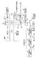
図11は、従来のラマン散乱光を用いてガス成分を分析するガス測定装置である。図11に示すように、従来のガス測定装置100は、ガス化炉101からガスタービン102に送給される配管103内を通過する測定試料であるガス(測定ガス)104に対してレーザー105を測定領域106に照射し、測定ガス104からのラマン散乱光(散乱光)107を分光し、測定データとして取り出すようにしたものである。従来のガス測定装置100では、レーザー照射装置110からレーザ発振によりレーザー光105を出力し、レーザー光105は石英窓111、112、電磁弁113を通過して測定ガス104へ照射する。レーザー光105が測定ガス104に照射されることで散乱光107が発生する。この測定ガス104からの散乱光107が、レンズ114、115、偏光素子116、ミラー117、フィルター118、レンズ119、分光器120を通過して測定ガス104からの散乱光107を分光し、ICCD(Intensified Charge Coupled Device)カメラ121により測定する。ICCDカメラ121で測定された測定データは測定部122で計測される。 FIG. 11 shows a gas measuring apparatus that analyzes gas components using conventional Raman scattered light. As shown in FIG. 11, the conventional
このように、レーザラマン法を用い散乱光107から測定データとして取り出すことで、燃料ガスのガス成分を数秒など短時間で分析することが可能となるため、燃料ガス化プラントにおいて燃料ガスの制御が可能となり、燃料ガス化プラントの信頼性の向上を図ることができる。 As described above, by extracting the measurement data from the
しかしながら、測定ガス104にダスト、油分が多く含まれている場合に、これらの油分がレーザ光を入射させるために設けられている石英窓112の内側表面など光学部品に付着すると、石英窓112の透過率が低下することにより、配管103内に入射されるレーザー105のレーザ出力が減衰し、得られる散乱光107の強度が低下するため、測定精度が悪化する、という問題がある。 However, when the
よって、燃料ガス成分の分析を行う際、レーザ照射用に用いる窓の交換をすることなく、分析性能の低下を防止し、常に安定したガス計測をすることができるガス分析装置の出現が切望されている。 Therefore, when analyzing fuel gas components, there is a strong demand for the appearance of a gas analyzer that can prevent degradation of analysis performance and always perform stable gas measurement without replacing the window used for laser irradiation. ing.
本発明は、前記問題に鑑み、分析性能の低下を防止しつつ、常時安定してガス計測を行うことができるガス分析装置を提供することを課題とする。 In view of the above-described problems, an object of the present invention is to provide a gas analyzer that can stably perform gas measurement at all times while preventing deterioration in analysis performance.
上述した課題を解決するため本発明の第1の発明は、油分を含む被測定ガスを抜出す被測定ガス抜出し管と、該被測定ガス抜出し管の壁面に窓が設けられ、該窓の前記被測定ガスが流通する方向の面側に光触媒をコーティングした光触媒層を有する光触媒コーティング窓と、前記光触媒コーティング窓に外部から波長が可視領域の第1のレーザ光、又は波長が紫外から真空紫外領域の第2のレーザ光の何れか一方又は両方を前記光触媒コーティング窓を通過して前記被測定ガスに照射させる光照射手段と、前記被測定ガス抜出し管の前記被測定ガスに第1のレーザ光を照射することで発生する散乱光を検出する検出器と、を有することを特徴とするガス分析装置にある。 In order to solve the above-described problems, a first invention of the present invention is provided with a measurement gas extraction pipe for extracting a measurement gas containing oil, and a window on a wall surface of the measurement gas extraction pipe. A photocatalyst coating window having a photocatalyst layer coated with a photocatalyst on the surface side in the direction in which the gas to be measured flows, and a first laser beam having a wavelength visible from the outside on the photocatalyst coating window, or a wavelength from ultraviolet to vacuum ultraviolet region A light irradiating means for irradiating the gas to be measured with one or both of the second laser beams through the photocatalyst coating window; and a first laser beam on the gas to be measured of the gas extraction pipe to be measured. And a detector for detecting scattered light generated by irradiating with a gas analyzer.
第2の発明は、第1の発明において、前記光照射手段が、波長が赤外領域のレーザ光を前記被測定ガスに照射するレーザ照射装置と、前記レーザ光を前記第1のレーザ光に変換する第1の波長変換器と、前記第1のレーザ光の一部又は全部を前記第2のレーザ光に変換する第2の波長変換器と、により構成されることを特徴とするガス分析装置にある。 According to a second invention, in the first invention, the light irradiating means irradiates the measured gas with a laser beam having a wavelength in an infrared region, and the laser beam is used as the first laser beam. A gas analysis comprising: a first wavelength converter for conversion; and a second wavelength converter for converting part or all of the first laser light into the second laser light. In the device.
第3の発明は、第1又は2の発明において、前記被測定ガス抜出し管の内壁に突出して設けられる一対の突出部を有し、一方の突出部の内壁に前記光触媒コーティング窓を設けることを特徴とするガス分析装置にある。 According to a third aspect of the present invention, in the first or second aspect of the present invention, the photocatalyst coating window is provided on the inner wall of one of the projecting portions, the pair of projecting portions projecting from the inner wall of the gas extraction pipe to be measured. The characteristic gas analyzer is.
第4の発明は、第1乃至3の何れか一つの発明において、前記光触媒コーティング窓と対向する壁面側に、前記第1のレーザ光を遮蔽する遮蔽部材を有することを特徴とするガス分析装置にある。 According to a fourth aspect of the present invention, in any one of the first to third aspects, the gas analyzer includes a shielding member that shields the first laser beam on a wall surface facing the photocatalyst coating window. It is in.
第5の発明は、第3又は4の発明において、前記光触媒コーティング窓が設けられている一方の突出部内に、不活性ガスを供給する不活性ガス供給手段を有することを特徴とするガス分析装置にある。 A fifth aspect of the invention is the gas analyzer according to the third or fourth aspect of the invention, further comprising an inert gas supply means for supplying an inert gas in one of the protrusions provided with the photocatalyst coating window. It is in.
第6の発明は、第2乃至5の何れか一つの発明において、前記第1のレーザ光が前記第2の波長変換器を迂回する迂回通路を有することを特徴とするガス分析装置にある。 A sixth invention is the gas analyzer according to any one of the second to fifth inventions, wherein the first laser beam has a bypass path for bypassing the second wavelength converter.
第7の発明は、第3乃至6の何れか一つの発明において、他方の突出部内に更に光触媒コーティング窓が設けられ、前記他方の突出部内に設けた前記光触媒コーティング窓と前記他方の突出部の内壁との間に、前記第1のレーザ光は透過し、前記第2のレーザ光は反射させるダイクロイックミラーを有することを特徴とするガス分析装置にある。 According to a seventh invention, in any one of the third to sixth inventions, a photocatalyst coating window is further provided in the other protrusion, and the photocatalyst coating window provided in the other protrusion and the other protrusion are provided. The gas analyzer includes a dichroic mirror that transmits the first laser beam and reflects the second laser beam between the inner wall and the inner wall.
第8の発明は、第3乃至6の何れか一つの発明において、前記一対の突出部内のうち他方の突出部内に第2の波長変換器が設けられ、前記第2の波長変換器と前記他方の突出部の内壁との間に、前記第1のレーザ光は透過させ、前記第2のレーザ光は反射させるダイクロイックミラーを有することを特徴とするガス分析装置にある。 According to an eighth invention, in any one of the third to sixth inventions, a second wavelength converter is provided in the other protrusion of the pair of protrusions, and the second wavelength converter and the other The gas analyzer includes a dichroic mirror that transmits the first laser beam and reflects the second laser beam between the inner wall of the protruding portion of the first laser beam.
第9の発明は、第8の発明において、前記一方の突出部内に、オゾンガスを供給するオゾンガス供給手段を有することを特徴とするガス分析装置にある。 According to a ninth aspect of the present invention, in the eighth aspect of the invention, an ozone gas supply means for supplying ozone gas is provided in the one projecting portion.
第10の発明は、第8又は9の発明において、前記他方の突出部内に、不活性ガスを供給する不活性ガス供給手段を有することを特徴とするガス分析装置にある。 A tenth invention is the gas analyzer according to the eighth or ninth invention, further comprising an inert gas supply means for supplying an inert gas in the other protrusion.
更に上述の課題を解決するため、更に下記構成を採用することもできる。
1) 即ち、前記一方の突出部内に、オゾンガスを供給するオゾンガス供給手段を設けるようにしてもよい。Furthermore, in order to solve the above-mentioned problem, the following configuration can also be adopted.
1) That is, you may make it provide the ozone gas supply means which supplies ozone gas in said one protrusion part.
本発明によれば、波長が紫外領域から真空紫外領域の第2のレーザ光を光触媒コーティング窓に照射することで、光触媒コーティング窓にコーティングした光触媒の機能が発揮されることにより光触媒コーティング窓の表面に付着した汚れを除去することができる。このため、波長が可視光領域の第1のレーザ光を光触媒コーティング窓を通過する際に光の強度が低減されることなく被測定ガスに照射することができると共に、第1のレーザ光を燃料ガスに照射することで散乱する散乱光の強度も低減されることなく測定することができる。これにより、窓を交換することなく、常時安定して被測定ガスの分析の測定精度を維持しつつ、測定することができる。 According to the present invention, by irradiating the photocatalyst coating window with the second laser light having a wavelength in the ultraviolet region to the vacuum ultraviolet region, the function of the photocatalyst coated on the photocatalyst coating window is exhibited, whereby the surface of the photocatalyst coating window. Dirt adhered to the surface can be removed. Therefore, when the first laser beam having a wavelength in the visible light region passes through the photocatalyst coating window, the gas to be measured can be irradiated without reducing the intensity of the light, and the first laser beam can be used as the fuel. The intensity of the scattered light scattered by irradiating the gas can be measured without being reduced. As a result, it is possible to perform measurement while maintaining the measurement accuracy of the analysis of the gas to be measured constantly without changing the window.
以下、この発明につき図面を参照しつつ詳細に説明する。なお、この実施例によりこの発明が限定されるものではない。また、下記実施例における構成要素には、当業者が容易に想定できるもの、あるいは実質的に同一のものが含まれる。 Hereinafter, the present invention will be described in detail with reference to the drawings. Note that the present invention is not limited to the embodiments. In addition, constituent elements in the following embodiments include those that can be easily assumed by those skilled in the art or those that are substantially the same.
本発明による実施例1に係る第一のガス分析装置について、図面を参照して説明する。
図1は、本発明による実施例1に係るガス分析装置の構成を簡略に示す概念図である。
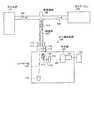
図1に示すように、本実施例に係る第一のガス分析装置10Aは、油分を含む被測定ガスとして燃料ガス11を抜出す燃料ガス抜出し管(被測定ガス抜出し管)12と、この燃料ガス抜出し管12に窓13が設けられ、この窓13の燃料ガス11が流通する方向の面側に光触媒として酸化チタン(TiO2)をコーティングしたTiO2層(光触媒層)14を有する酸化チタン(TiO2)コーティング窓15と、TiO2コーティング窓15に外部から波長が可視領域の第1のレーザ光16、波長が紫外から真空紫外領域の第2のレーザ光17の両方をTiO2コーティング窓15を通過して燃料ガス11に照射させる光照射手段18と、燃料ガス抜出し管12の燃料ガス11に第1のレーザ光16を照射することで発生する散乱光19を検出する検出器20と、を有するものである。A first gas analyzer according to a first embodiment of the present invention will be described with reference to the drawings.
FIG. 1 is a conceptual diagram schematically showing the configuration of a gas analyzer according to a first embodiment of the present invention.
As shown in FIG. 1, a
被測定ガスである燃料ガス11中の計測対象のガス成分としては、例えば一酸化窒素(NO)、一酸化炭素(CO)、水(H2O)、二酸化窒素(NO2)、メタン(CH4)、アンモニア、ベンゼン等を例示することができる。Examples of gas components to be measured in the
燃料ガス抜出し管12は煙道21に連結され、煙道21内を流れる燃料ガス11を燃料ガス抜出し管12から一部抜出す。燃料ガス抜出し管12より燃料ガス11を連続的に抜出すことで、燃料ガス11中のガス成分を連続して測定することができる。 The fuel
また、本実施例に係る第一のガス分析装置10Aにおいては、光照射手段18は、波長が赤外領域のレーザ光22を燃料ガス11に照射するレーザ照射装置23と、レーザ光22を第1のレーザ光16に変換する第1の波長変換器24と、第1のレーザ光16の一部を第2のレーザ光17に変換する第2の波長変換器25と、により構成されている。 Further, in the
また、レーザ照射装置23から照射されるレーザ光22としては、例えばYAG結晶に微量のNd(ネオジウム)を添加した結晶体に強い励起光を照射することで得られるYAGレーザ(波長:1064nm)が用いられる。また、レーザ照射装置23より照射されるレーザ光22としては、YAGレーザに限定されるものではなく、波長が赤外領域の光であれば用いることができる。 Further, as the
レーザ光22は、第1の波長変換器24において波長が可視領域の第1のレーザ光16に変換される。第1の波長変換器24には、非線形光学結晶が備えられ、レーザ光22を非線形光学結晶に通して第1のレーザ光16を得るようにしている。非線形光学結晶としては、例えば、ベータバリウムボライト(β-BaB2O4:BBO)結晶、KTiOPO4(KTP)結晶などが例示される。レーザ光22は、波長が1064nmのYAGレーザである時は、第1のレーザ光16はその第二高調波である波長が532nmのレーザ光に変換される。また、第1のレーザ光16は第二高調波(波長:532nm)に限定されるものではなく、波長が可視領域のレーザ光であればよい。The
第1の波長変換器24で波長変換された第1のレーザ光16の一部は、第2の波長変換器25において第2のレーザ光17に変換される。第1の波長変換器25には、非線形光学結晶が備えられ、第1のレーザ光16を非線形光学結晶に通して第2のレーザ光17を得るようにしている。非線形光学結晶としては、例えばBBO結晶などが例示される。第2のレーザ光17は波長が紫外領域のレーザ光であり、第2のレーザ光17のパルス波長は、例えば213nm以上355nm以下であるのが好ましい。また、第2のレーザ光17のパルス波長は、レーザ発振の容易さなどから、例えば213nm、266nm、355nmを用いるのが特に好ましい。これは、非線形光学結晶を設置するだけで、第2のレーザ光17を発振できるので、設置が容易であり、メンテナンス性も良いためである。なお、第2のレーザ光17の波長は213nm以上355nm以下に限定されるものではなく、第2のレーザ光17は波長が紫外領域のレーザ光であればよい。 A part of the
また、第2の波長変換器25は、第1のレーザ光16の一部を第2のレーザ光17に波長変換しているが、本発明はこれに限定されるものではなく、第1のレーザ光16の全部を第2のレーザ光17に波長変換するようにしてもよい。 Further, the
第1のレーザ光16と、第2の波長変換器25で波長が変換された第2のレーザ光17とは、同軸で進行し、反射ミラー26で反射され、TiO2コーティング窓15に向けて光路を変更し、集光レンズ27で集光された後、第1のレーザ光16及び第2のレーザ光17はTiO2コーティング窓15に同時に到達する。The
また、レーザ照射装置23から照射されるレーザ光22のパルス時間幅(レーザパルス幅)は0.1ナノ秒(ns)以上100ナノ秒(ns)以下、より好ましくは1ns以上10ns以下であることが好ましい。これは、パルス時間幅が100nsを越えると、確保すべき光路が長くなるためであり、パルス時間幅が0.1nsを下回ると窓13に照射される光量が少なくなるため、効率的な光触媒の機能が達成されないからである。 Further, the pulse time width (laser pulse width) of the
また、レーザ照射装置23から照射されるレーザ光22のレーザエネルギー密度は1MW/cm2以上1000MW/cm2以下、より好ましくは10MW/cm2以上100MW/cm2以下であることが好ましい。これはレーザエネルギー密度が1MW/cm2を下回ると、効率的な光触媒の機能が達成されないためであり、レーザエネルギー密度が1000MW/cm2を超えると、光密度が高くなるため、窓13の破損を生じる虞があるためである。The laser energy density of the
よって、第2のレーザ光17の波長が213nm以上355nm以下であり、第2のレーザ光17のパルス時間幅が0.1ns以上100nsであると共に、レーザエネルギー密度が1MW/cm2以上1000MW/cm2以下とすることで、レーザ光22を波長変換して得られる第2のレーザ光17によりTiO2の光触媒の機能を有効に発揮させることができる。Therefore, the wavelength of the
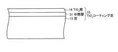
燃料ガス抜出し管12の内壁12aに一対の突出部28−1、28−2が突出して設けられている。突出部28−1、28−2は、燃料ガス抜出し管12を挟んで対抗して設けられている。本実施例においては、TiO2コーティング窓15は、一方の突出部28−1の内壁28aに設けられている。TiO2コーティング窓15は、図2に示すように、内壁28aに設けた窓13の上に中間層31、TiO2層14の順で燃料ガス抜出し管12の内側に向かって積層されている。A pair of projecting portions 28-1 and 28-2 are provided to project from the
窓13は、第1のレーザ光16、第2のレーザ光17を透過させるものとする。窓13の材料には、例えばソーダライムガラスを用いるのが好ましい。中間層31には、例えばシリカ(SiO2)を主成分として含む材料などが用いられる。The window 13 transmits the
窓13の材料として、例えばソーダライムガラスを用い、このソーダライムガラスの表面上にTiO2層14を積層すると、ソーダライムガラスを構成するナトリウムイオン(Na+)がTiO2と反応してTiO2の光触媒の機能を低下させ、TiO2層14の表面に入射した光が乱れて進行するため、対象物が歪んで見えてしまう。For example, soda lime glass is used as the material of the window 13, and when a TiO2 layer 14 is laminated on the surface of the soda lime glass, sodium ions (Na+ ) constituting the soda lime glass react with TiO2 to react with TiO2. Since the function of the photocatalyst is reduced and the light incident on the surface of the TiO2 layer 14 is disturbed and proceeds, the object appears to be distorted.
これに対し、TiO2コーティング窓15のように、窓13とTiO2層14との間に中間層31を設けることで、中間層31がソーダライムガラスを構成するNa+がTiO2層14に侵入するのを防ぐため、TiO2の光触媒の機能の低下を防ぐことができる。このため、TiO2層14の表面に入射した光が乱れることなく進行することができるため、測定用の窓に用いることができる。On the other hand, by providing the intermediate layer 31 between the window 13 and the TiO2 layer 14 like the TiO2 coating window 15, the Na+ constituting the soda lime glass in the intermediate layer 31 becomes the TiO2 layer 14. In order to prevent intrusion, it is possible to prevent a decrease in the function of the TiO2 photocatalyst. For this reason, since the light incident on the surface of the TiO2 layer 14 can travel without being disturbed, it can be used for a measurement window.
TiO2層14の表面には、燃料ガス11中に含まれるタールに起因するミストや、油分など有機物に起因して発生する固着物が付着する。第2のレーザ光17がTiO2コーティング窓15に照射されることで、第2のレーザ光17は紫外光であるため、TiO2層14の表面では光触媒の機能が発揮される。TiO2の光触媒としての機能が発揮されることにより、燃料ガス11中に含まれるミストや、有機物などの固着物がTiO2層14の表面に生成されるのを防止することができるため、TiO2層14の表面が汚染されるのを防止することができる。The surface of the TiO2 layer 14 is attached with mist caused by tar contained in the
また、突出部28−1には、突出部28−1内に不活性ガス34を供給する不活性ガス供給部(不活性ガス供給手段)35を設けている。不活性ガス供給部35より突出部28−1内に不活性ガス34を供給することで、TiO2層14の表面に積層される燃料ガス11に起因する煤塵をパージすることができる。不活性ガス34としては、例えばN2ガス、Arガスなどを用いることができる。Further, the protruding portion 28-1 is provided with an inert gas supply portion (inert gas supply means) 35 for supplying the inert gas 34 into the protruding portion 28-1. By supplying the inert gas 34 from the inert
また、第2のレーザ光17として紫外光を用いているが、波長が200nm以下の真空紫外領域では、酸素分子の光吸収の影響があるので、第2のレーザ光17が燃料ガス11に照射される周囲環境を不活性ガス34で充填させることで酸素分子の光吸収の影響を抑制することができる。 In addition, although ultraviolet light is used as the
TiO2層14の膜厚としては、例えば、10nm以上1000nm以下が好ましい。これは、TiO2層14の膜厚が10nmより小さいと、TiO2層14が中間層31から剥離し易いためである。また、TiO2層14の膜厚が1000nmより大きいと、光の透過率が低下するためである。なお、TiO2層14の膜厚は、特に上記範囲に限定されるものではなく、TiO2層14の光触媒の機能が発揮されるものであればよい。The film thickness of the TiO2 layer 14 is preferably 10 nm or more and 1000 nm or less, for example. This is because the thickness of the TiO2 layer 14 is 10nm smaller is liable TiO2 layer 14 is separated from the intermediate layer 31. Further, when the thickness of the TiO2 layer 14 is larger than 1000 nm, the light transmittance is lowered. The thickness of the TiO2 layer 14 is not particularly limited to the above-mentioned range, as long as the function of the photocatalyst of the TiO2 layer 14 is exhibited.
また、光触媒としてTiO2を用いているが、TiO2を用いる場合、触媒性能に優れたアナターゼ型の結晶構造を有するTiO2を用いるのが特に好ましい。また、本実施例に係る第一の排ガス分析装置10Aにおいては、光触媒の材料としてTiO2を用いているが、本発明はこれに限定されるものではなく、酸化亜鉛(ZnO)、硫化カドミウム(CdS)、酸化鉄なども用いることができる。Further, TiO2 is used as a photocatalyst, but when TiO2 is used, it is particularly preferable to use TiO2 having an anatase type crystal structure excellent in catalytic performance. Further, in the first
TiO2コーティング窓15と対向する壁面側に、第1のレーザ光16を遮蔽するダンパ(遮蔽部材)36が設けられている。ダンパ36は、燃料ガス抜出し管12の他方の突出部28−2に設けられている。第2の波長変換器25において波長変換されなかった第1のレーザ光16はTiO2コーティング窓15を通過してダンパ36に吸収される。A damper (shielding member) 36 that shields the
また、第1のレーザ光16は燃料ガス抜出し管12内に抜き出された燃料ガス11中のガス成分、煤塵等で散乱し、散乱光19を発生する。この第1のレーザ光16から発生した散乱光19は、第1のレーザ光16が燃料ガス11中のCOなどガス成分に入射することで発生するラマン散乱光と、燃料ガス11中の煤塵等に入射することで散乱するミー散乱光(光の波長と同程度かそれ以上の粒子による散乱光)とが含まれる。 Further, the
この第1のレーザ光16から発生した散乱光19は、燃料ガス抜出し管12内からTiO2コーティング窓15を通過して反射ミラー37で反射され、集光レンズ38で集光された後、分光器39で分光された後、検出器20で検出され、測定される。The
よって、第2のレーザ光17がTiO2層14に照射されることで、TiO2層14の表面に付着した燃料ガス11中に含まれるミストや、有機物などの固着物を光触媒の」効果により除去することができる。このため、TiO2コーティング窓15を通過する第1のレーザ光16のレーザ出力が低下されることなく燃料ガス11に照射することができる。また、散乱光19がTiO2コーティング窓15を通過する際、光の強度を低下することなく検出器20に照射し、測定することができる。Therefore, by irradiating the TiO2 layer 14 with the
また、図3は、計測チャンネルと信号強度との関係を示す図である。
尚、図3の測定には、波長が532nm程度のレーザ光を用いて行なったものである。
図3に示すように、測定ガスとしてH2ガスを用いたときには、波長が693nm付近でピークが観測される。よって、測定ガスとしてH2ガスを用いるときには、波長が693nm付近の光を検出用として用いることで高い測定性能が得られる。FIG. 3 is a diagram showing the relationship between measurement channels and signal strength.
Note that the measurement in FIG. 3 was performed using laser light having a wavelength of about 532 nm.
As shown in FIG. 3, when H2 gas is used as the measurement gas, a peak is observed when the wavelength is around 693 nm. Therefore, when H2 gas is used as the measurement gas, high measurement performance can be obtained by using light having a wavelength in the vicinity of 693 nm for detection.
図4は、時間と水素の信号強度との関係を示す図である。
図4中、試験例1は、窓13にTiO2層14をコーティングしたTiO2コーティング窓15を有する本実施例に係る第一のガス分析装置10Aを用いて行なった試験結果を示す(図4中、太線)。比較例1は、窓13にTiO2層14をコーティングしていない従来より用いられている図11に示すようなラマン散乱光を測定するガス測定装置を用いて行なった試験結果を示す(図4中、破線)。
尚、図4の測定には、波長が532nm程度のレーザ光を用いて行なったものである。また、H2ガスを測定ガスとして用いて行なっているので、図3に示すように、波長が693nm付近の光を検出して行なった。
図4に示すように、従来より用いられている図11に示すようなラマン散乱光を測定するガス測定装置を用いてガス成分の分析を行った比較例1の場合、時間が経過するに従ってH2の信号強度は低下していった。これに対し、本実施例に係る第一のガス分析装置10Aを用いてガス成分の分析を行った試験例1では、常時安定してH2の信号強度が高く維持できた。よって、本実施例に係る第一のガス分析装置10Aを用いてガス成分の分析を行うことで、散乱光19の光の強度を低下させることなく検出器20で検出し、安定してガス成分の測定をすることができる。FIG. 4 is a diagram showing the relationship between time and the signal intensity of hydrogen.
In FIG. 4, Test Example 1 shows the results of a test performed using the
Note that the measurement of FIG. 4 was performed using laser light having a wavelength of about 532 nm. Further, since H2 gas was used as the measurement gas, as shown in FIG. 3, light having a wavelength of around 693 nm was detected.
As shown in FIG. 4, in the case of Comparative Example 1 in which a gas component was analyzed using a conventionally used gas measuring device for measuring Raman scattered light as shown in FIG. The signal strength of2 decreased. On the other hand, in Test Example 1 in which the gas component was analyzed using the
また、TiO2層14の光触媒の機能を発揮させる第2のレーザ光17と、燃料ガス11のガス成分の分析用に用いる第2のレーザ光17とはレーザ照射装置23から照射される単一のレーザ光22を用いている。また、レーザ照射装置23から照射されるレーザ光22はパルス時間幅で調整することができる。よって、燃料ガス11のガス成分の分析を行う装置の構成を簡略にすることができると共に、ガス成分の分析精度を向上させることができる。In addition, the
また、検出器20としては、例えば、ICCD(Intensified Charge Coupled Device)カメラなどが用いられる。検出器20としてICCDカメラを用い、ラマン散乱光、ミー散乱光を検知することにより、燃料ガス11中のガス成分、煤塵を監視することができる。これにより、燃料ガス11中に含まれるガス成分、煤塵等を検知することができる。 For example, an ICCD (Intensified Charge Coupled Device) camera is used as the
燃料ガス抜出し管12内は燃料ガス11が流れているため分析中は開けることができないが、燃料ガス抜出し管12内の煤塵の有無を検出器20で検知することで、燃料ガス抜出し管12内の燃料ガス11中の煤塵に起因する汚れを事前に予測することができるため、N2ガス34によりTiO2層14の表面に積層される燃料ガス11に起因する煤塵をパージすることもできる。The fuel
なお、検出器20として、ICCDカメラを用いているが、本発明はこれに限定されるものではなく、光電子増倍管(PMT:Photomultiplier)など第1のレーザ光16の散乱光19を検出できるものであればよい。 Although the ICCD camera is used as the
このように、本実施例に係る第一のガス分析装置10Aによれば、波長が紫外領域の第2のレーザ光17をTiO2コーティング窓15に照射することで、TiO2層14の表面に付着した燃料ガス11中に含まれるミストや、有機物などの固着物をTiO2の光触媒の機能が発揮されることにより除去することができる。よって、波長が可視領域の第1のレーザ光16がTiO2コーティング窓15を通過する際に光の強度が低減されることなく燃料ガス11に照射することができると共に、第1のレーザ光16を燃料ガス11に照射することで散乱する散乱光19の強度も低減されることなく測定することができる。Thus, according to the
従って、TiO2コーティング窓15を通過する第1のレーザ光16と散乱光19との光の強度の低下を抑制することができるため、窓13など光学部品の汚れにより第1のレーザ光16及び散乱光19のレーザ出力低下に伴い検出感度が低下し、測定能力が低下するのを防止し、窓13を交換することなく、常時安定して燃料ガス11の分析の測定精度を維持しつつ、測定することができる。Accordingly, it is possible to suppress a decrease in the intensity of the
また、本実施例に係る第一のガス分析装置10Aにおいては、TiO2コーティング窓15を突出部28−1の内壁28aに設けるようにしているが、本発明はこれに限定されるものではなく、燃料ガス11の通路の壁面に設けるようにすればよいため、燃料ガス抜出し管12の壁面にTiO2コーティング窓15を設けるようにしてもよい。In the
また、本実施例に係る第一のガス分析装置10Aにおいては、被測定ガスとしてボイラ等から排出される燃料ガス11中のガス分析について説明したが、本発明はこれに限定されるものではなく、他の燃焼設備等から排出されるガスを被測定用ガスとして分析を行うようにしてもよい。 In the
本発明による実施例2に係る第二のガス分析装置について、図5を参照して説明する。
図5は、本発明による実施例2に係る第二のガス分析装置の構成を簡略に示す概念図である。
本実施例に係る第二のガス分析装置は、図1に示す実施例1に係る第一のガス分析装置10Aの構成と同様であるため、同一部材には同一の符号を付して重複した説明は省略する。A second gas analyzer according to the second embodiment of the present invention will be described with reference to FIG.
FIG. 5 is a conceptual diagram schematically showing the configuration of the second gas analyzer according to the second embodiment of the present invention.
The second gas analyzer according to the present embodiment is the same as the configuration of the
図5に示すように、本実施例に係る第二のガス分析装置10Bは、前記図1に示した実施例1に係る第一のガス分析装置10Aの第1のレーザ光16が第2の波長変換器25を迂回する迂回通路41を有するものである。 As shown in FIG. 5, in the
迂回通路41は、第1のレーザ光16を分光するハーフミラー42と、反射ミラー43−1、43−2と、第1のレーザ光16を透過すると共に、第2のレーザ光17を反射するダイクロイックミラー44と、で構成されている。また、第2の波長変換器25の後流側には、凹レンズ45が設けられ、凹レンズ45は第2の波長変換器25とダイクロイックミラー44との間に配置されている。また、迂回通路41には、凸形状である集光レンズ27が設けられ、集光レンズ27は反射ミラー43−2とダイクロイックミラー44との間に配置されている。 The
レーザ照射装置23から照射されたレーザ光22は第1の波長変換器24で波長変換され、第1のレーザ光16となった後、ハーフミラー42で分光された第1のレーザ光16aの一部は、第2の波長変換器25で波長変換され、第2のレーザ光17となる。また、第2の波長変換器25とダイクロイックミラー44との間に凹レンズ45を設けているため、第2のレーザ光17の光束は拡大される。また、ダイクロイックミラー44は、第1のレーザ光16aを透過し、第2のレーザ光17を反射するため、第1のレーザ光16aはダイクロイックミラー44を透過してダンパ46で吸収され、第2のレーザ光17はダイクロイックミラー44で反射される。このため、第2のレーザ光17のみ光束を拡大しながらTiO2コーティング窓15に照射させることができる。The
よって、第2のレーザ光17をTiO2層14の全面に照射させることができるため、窓13の全面において窓汚れなどに起因する窓透過率の低下が回避できる。そのため、TiO2層14の全面に照射される散乱光19は窓汚れによる光量低下が起こることなく、検出器20に照射され、検出用に用いることができる。Therefore, since the
ハーフミラー42で分光された他の第1のレーザ光16bは、迂回通路41を経由してTiO2コーティング窓15に導くことができる。即ち、ハーフミラー42で反射され分光された第1のレーザ光16bは、反射ミラー43−1、43−2で光路を変更し、ダイクロイックミラー44を透過してTiO2コーティング窓15に導かれる。第1のレーザ光16bが迂回通路41を経由することで、ハーフミラー42から迂回通路41を経由してTiO2コーティング窓15までの光路の長さをハーフミラー42から第2の波長変換器25を通過してTiO2コーティング窓15までの光路の長さよりも長くすることができる。The other first laser light 16 b split by the
このため、第2の波長変換器25で第1のレーザ光16aを波長変換した第2のレーザ光17は、迂回通路41を経由する第1のレーザ光16bよりもTiO2コーティング窓15に早く照射させることができる。TiO2コーティング窓15に第2のレーザ光17を照射することによりTiO2コーティング窓15のTiO2層14の表面で光触媒としての機能が働くため、迂回通路41を経由した第1のレーザ光16bがTiO2コーティング窓15に到着する前に、予め燃料ガス11中に含まれるミスト、有機物などの固着物がTiO2層14の表面に生成されるのを防止することができる。For this reason, the
よって、第2のレーザ光17より遅れて燃料ガス11に照射される第1のレーザ光16bが、TiO2コーティング窓15で第1のレーザ光16bのレーザ出力が低下するのを防ぐことができる。従って、第1のレーザ光16bのレーザ出力を低下させることなく燃料ガス11に照射させることができる。また、散乱光19がTiO2コーティング窓15を通過する際、光の強度を低下することなく検出器20に照射し、測定することができる。Therefore, it is possible to prevent the first laser beam 16 b irradiated to the
迂回通路41の長さは、第1のレーザ光16のパルス時間幅に応じて調整する。図6は、第1のレーザ光のパルス時間幅と第2のレーザ光のパルス時間幅との関係を示す図である。図6に示すように、第1のレーザ光16のパルスと第2のレーザ光17のパルスとを10nsとしたとき、第1のレーザ光16、第2のレーザ光17は、1nsで30cm進む。そのため、第2のレーザ光17が第1のレーザ光16よりも10ns遅れてTiO2コーティング窓15に照射されるようにするためには、迂回通路41を経由して遅延する分の長さが3mとなるように調整する必要がある。The length of the
図7は、第1のレーザ光と第2のレーザ光との光路を簡略に示す図である。図7に示すように、第1のレーザ光16bが第2のレーザ光17よりも10ns遅れてTiO2コーティング窓15に照射されるようにするためには、下記式(1)、(2)を満たすようにし、遅延する分の光路の長さが3mとなるように調整する。
A+C=3m ・・・(1)
B=D ・・・(2)
但し、ハーフミラー42と反射ミラー43−1との距離をA、ハーフミラー42とダイクロイックミラー44との距離をB、反射ミラー43−2とダイクロイックミラー44との距離をC、反射ミラー43−1と反射ミラー43−2との距離をD、とする。FIG. 7 is a diagram simply showing an optical path between the first laser beam and the second laser beam. As shown in FIG. 7, in order to irradiate the TiO2 coating window 15 with the first laser beam 16b 10ns later than the
A + C = 3m (1)
B = D (2)
However, the distance between the
このように、本実施例に係る第二のガス分析装置10Bによれば、第1のレーザ光16bは迂回通路41を経由させ、第1のレーザ光16bを第2のレーザ光17よりも遅れてTiO2コーティング窓15に照射することで、予め燃料ガス11中に含まれるミストや、有機物などの固着物がTiO2層14の表面に付着するのを防止することができる。燃料ガス11のガス分析の開始時点より第1のレーザ光16がTiO2コーティング窓15を通過する際に光の強度が低減されることなく燃料ガス11に照射することができると共に、第1のレーザ光16を燃料ガス11に照射することで散乱する散乱光19の強度も低減されることなく測定することができる。Thus, according to the
また、第2の波長変換器25とダイクロイックミラー44との間に設けた凹レンズ45により第2のレーザ光17の光束を拡大し、第2のレーザ光17をTiO2層14の全面に照射させることができるため、窓13の全面において窓汚れなどに起因する窓透過率の低下が回避できる。そのため、TiO2層14の全面に照射される散乱光19を窓汚れによる光量低下を生じることなく、検出器20に照射させることができ、検出用に用いることができる。Further, a
従って、燃料ガス11のガス分析の開始時点より窓13など光学部品の汚れにより第1のレーザ光16及び散乱光19のレーザ出力の低下を防止でき、窓13を交換することなく、常時安定して燃料ガス11の分析の測定精度を維持しつつ測定することができる。 Accordingly, it is possible to prevent the laser output of the
また、本実施例に係る第二のガス分析装置10Bにおいては、第2の波長変換器25とダイクロイックミラー44との間に凹レンズ45を設けているが、本発明はこれに限定されるものではなく、凹レンズ45は設けなくてもよい。また、反射ミラー43−2とダイクロイックミラー44との間に集光レンズ27を設けているが、本発明はこれに限定されるものではなく、集光レンズ27は設けなくてもよい。この場合には、集光レンズ27はダイクロイックミラー44と反射ミラー37との間に設けるようにする。 In the
本発明による実施例3に係るガス分析装置について、図8を参照して説明する。
図8は、本発明による実施例3に係るガス分析装置の構成を簡略に示す概念図である。
本実施例に係る第三のガス分析装置10Cは、図1に示す実施例1に係る第一のガス分析装置10A又は図5に示す実施例2に係る第二のガス分析装置10Bの構成と同様であるため、同一部材には同一の符号を付して重複した説明は省略する。A gas analyzer according to Example 3 of the present invention will be described with reference to FIG.
FIG. 8 is a conceptual diagram schematically showing the configuration of the gas analyzer according to the third embodiment of the present invention.
The
図8に示すように、本実施例に係る第三のガス分析装置10Cは、突出部28−1内に、オゾン(O3)ガス51を供給するオゾン(O3)ガス供給部(O3ガス供給手段)52を有するものである。As shown in FIG. 8, a
O3ガス51を突出部28−1内に供給し、窓13にコーティングされたTiO2層14に第2のレーザ光17を照射することで、O3は、TiO2の表面において下記式(3)のように反応して酸化剤を生成し、TiO2層14の表面において光触媒効果をより向上させることができる。このため、燃料ガス11中に含まれるミスト、固着物がTiO2層14の表面に生成されるのを更に効果的に防止することができる。
O3 → O・+O2- ・・・(3)O3 gas 51 is supplied into the protrusion 28-1, by irradiating the
O3 → O ・ + O2-・ ・ ・ (3)
また、突出部28−1内にO3ガス51を供給することで、TiO2層14の表面に積層される燃料ガス11に起因する煤塵などをパージすることができる。Further, by supplying the O3 gas 51 into the protruding portion 28-1, dust or the like caused by the
よって、本実施例に係る第三のガス分析装置10Cによれば、突出部28−1内にO3ガス51を供給し、TiO2層14の表面に生成される燃料ガス11中のミスト、固着物などの酸化分解を促進することで、ミスト、固着物の分解効率を更に向上させることができると共に、TiO2層14の表面に積層される煤塵などをパージすることができる。Therefore, according to the
このため、窓13など光学部品の汚れにより第1のレーザ光16及び散乱光19のレーザ出力の低下をより確実に防止でき、窓13を交換することなく、燃料ガス11の分析の測定精度を維持しつつより安定してガス分析を行うことができる。 For this reason, it is possible to more reliably prevent the laser output of the
本発明による実施例4に係る第四のガス分析装置について、図9を参照して説明する。
図9は、本発明による実施例4に係るガス分析装置の構成を簡略に示す概念図である。
本実施例に係る第四のガス分析装置10Dは、図1に示す実施例1に係る第一のガス分析装置10A乃至図8に示す実施例3に係る第三のガス分析装置10Cの構成と同様であるため、同一部材には同一の符号を付して重複した説明は省略する。A fourth gas analyzer according to Example 4 of the present invention will be described with reference to FIG.
FIG. 9 is a conceptual diagram schematically showing the configuration of the gas analyzer according to the fourth embodiment of the present invention.
The
図9に示すように、本実施例に係る第四のガス分析装置10Dは、前記図1に示した実施例1に係る第一のガス分析装置10Aの対向する一対の突出部28−1、28−2内にTiO2コーティング窓15−1、15−2を各々設けてなるものである。
即ち、図9に示すように、本実施例に係る第四のガス分析装置10Dは、前記図1に示した実施例1に係る第一のガス分析装置10Aの他方の突出部28−2内に更にTiO2コーティング窓15−2が設けられ、突出部28−2内に設けたTiO2コーティング窓15−2と突出部28−2の内壁28aとの間に、第1のレーザ光16は透過し、第2のレーザ光17は反射させるダイクロイックミラー61を有するものである。As shown in FIG. 9, the
That is, as shown in FIG. 9, the
TiO2コーティング窓15−1、15−2は、TiO2層14−1、14−2が燃料ガス抜出し管12の内側に対向するように配置されている。TiO2コーティング窓15−1は、第2のレーザ光17の入射方向から、窓13−1、中間層31−1、TiO2層14−1の順に配置されている。TiO2コーティング窓15−2は、ダイクロイックミラー61で反射した第2のレーザ光17の入射方向から、窓13−2、中間層31−2、TiO2層14−2の順に配置されている。The TiO2 coating windows 15-1 and 15-2 are arranged so that the TiO2 layers 14-1 and 14-2 face the inside of the fuel
突出部28−2内にダイクロイックミラー61を設けることで、TiO2コーティング窓15−1、15−2を透過した第1のレーザ光16はダイクロイックミラー61を透過し、第2のレーザ光17のみ反射させることができる。このため、ダイクロイックミラー61で反射された第2のレーザ光17をTiO2コーティング窓15−1、15−2の表面のTiO2層14−1、14−2に照射させることができる。By providing the
これにより、TiO2コーティング窓15−1、15−2の表面に第2のレーザ光17が照射される時間を増大させることができるため、TiO2層14−1、14−2に安定して第2のレーザ光17を照射させることができ、燃料ガス11中に含まれるミスト、有機物などの固着物に起因するTiO2層14−1、14−2の表面の汚れを安定して除去することができる。As a result, the time during which the
また、ダイクロイックミラー61で第1のレーザ光16は透過され、分光器39に到達することはないため、測定ノイズを除去することができ、測定精度を向上させることができる。 Further, since the
また、突出部28−1には突出部28−1内にO3ガス51を供給するO3ガス供給部52を設けている。突出部28−1内にO3ガス51を供給することで、TiO2層14−1の表面に積層される燃料ガス11に起因する煤塵などをパージすることができると共に、TiO2層14−1の表面に生成される燃料ガス11中のミスト、固着物などの酸化分解を促進することができる。Further, there is provided a O3
また、突出部28−2内に不活性ガス62を供給する不活性ガス供給部63を設けている。突出部28−2内に不活性ガス62を供給することで、TiO2層14−2の表面に積層される燃料ガス11に起因する煤塵などをパージすることができる。不活性ガスとしては、例えばN2ガス、Arガスなどを用いることができる。Moreover, the inert gas supply part 63 which supplies the inert gas 62 in the protrusion part 28-2 is provided. By supplying the inert gas 62 into the protruding portion 28-2, dust or the like caused by the
従って、本実施例に係る第四のガス分析装置10Dによれば、突出部28−2内にTiO2コーティング窓15−2と、TiO2コーティング窓15−2と突出部28−2の内壁28aとの間にダイクロイックミラー61とを設けることで、TiO2コーティング窓15−1、15−2のTiO2層14−1、14−2に安定して第2のレーザ光17を照射させることができる。このため、TiO2層14−1、14−2の表面に付着した燃料ガス11中に含まれるミスト、有機物などの固着物をTiO2の光触媒の機能が発揮されることによりTiO2層14−1、14−2の表面の汚れを安定して除去することができる。Therefore, according to the
よって、第1のレーザ光16及び散乱光19のレーザ出力の低下を更に確実に防止でき、窓13を交換することなく、燃料ガス11の分析の測定精度を維持しつつ更に安定してガス分析を行うことができる。 Therefore, the laser output of the
また、第2のレーザ光17がTiO2層14−1の表面に照射される光量を更に増加させたい場合には、ダイクロイックミラー61を複数設け、第2のレーザ光17の反射回数を増大させ、多重反射させ、第2のレーザ光17をTiO2層14−1の表面に照射させるようにようにする。In order to further increase the amount of light irradiated to the surface of the TiO2 layer 14-1 by the
また、本実施例に係る第四のガス分析装置10Dにおいては、突出部28−1、28−2内にTiO2コーティング窓15−1、15−2を設けるようにしているが、本発明はこれに限定されるものではなく、TiO2コーティング窓15−1のTiO2層14−1の表面が第1のレーザ光16及び散乱光19のレーザ出力の低下を抑制することができればよいため、突出部28−2内にTiO2コーティング窓15−2を設けなくてもよい。Further, in the
また、本実施例に係る第四のガス分析装置10Dにおいては、突出部28−1内にO3ガス51を供給するようにしているが、本発明はこれに限定されるものではなく、突出部28−1内にN2ガス62を供給するようにしてもよい。また、O3ガス51、不活性ガス34の両方を供給するようにしてもよい。Further, in the
本発明による実施例5に係る第五のガス分析装置について、図10を参照して説明する。
図10は、本発明による実施例5に係る第五のガス分析装置の構成を簡略に示す概念図である。
本実施例に係る第五のガス分析装置は、図1に示す実施例1に係る第一のガス分析装置10A乃至図9に示す実施例4に係る第四のガス分析装置10Dの構成と同様であるため、同一部材には同一の符号を付して重複した説明は省略する。A fifth gas analyzer according to Embodiment 5 of the present invention will be described with reference to FIG.
FIG. 10 is a conceptual diagram schematically showing the configuration of the fifth gas analyzer according to the fifth embodiment of the present invention.
The fifth gas analyzer according to this embodiment has the same configuration as the
図10に示すように、本実施例に係る第五のガス分析装置10Eは、前記図1に示した実施例1に係る第一のガス分析装置10Aの突出部28−2内に第2の波長変換器25が設けられ、第2の波長変換器25と突出部28−2の内壁28aとの間に、第1のレーザ光16は透過し、第2のレーザ光17を反射させるダイクロイックミラー61と、レーザ照射領域である中心部分に孔71を有する板72と、第2の波長変換器25と板72との間に不活性ガス62を供給する不活性ガス供給部63と、を有するものである。 As shown in FIG. 10, the
板72にはレーザの照射領域である中心部分に孔71が設けられているため、第1のレーザ光16は孔71を通過し、第2の波長変換器25において第1のレーザ光16の一部は波長変換され第2のレーザ光17となる。ダイクロイックミラー61は、第1のレーザ光16を透過し、第2のレーザ光17を反射するようにしたものであるため、第1のレーザ光16はダイクロイックミラー61を通過し、ダンパ36で遮蔽される。また、第2のレーザ光17はダイクロイックミラー61で反射される。 Since the
また、板72と第2の波長変換器25との間には、凹レンズ73が設けられている。ダイクロイックミラー61で反射され、第2の波長変換器25を通過した第2のレーザ光17は、凹レンズ73で光束が広がるため、孔71を通過し、TiO2コーティング窓15の表面のTiO2層14全体に照射させることができる。また、第2の波長変換器25で波長変換された第2のレーザ光17を反射ミラー37を通過させた後、窓13に照射するようにした場合、第2のレーザ光17の一部が反射ミラー37で遮断される虞がある。これに対し、第2の波長変換器25で波長変換した第2のレーザ光17は、第2の波長変換器25とTiO2層14との間に第2のレーザ光17を遮断する反射ミラー37などは設けられていない。このため、第2のレーザ光17は反射ミラー37などにより遮断されることなくTiO2層14に照射することができる。A
よって、TiO2コーティング窓15の表面のTiO2層14全体に第2のレーザ光17を照射することで、TiO2層14の表面全体に付着した燃料ガス11中に含まれるミスト、有機物などの固着物をTiO2の光触媒の機能が発揮されることにより除去することができるため、検出器20で検出される散乱光19の光信号を増大させることができる。Therefore, by irradiating the entire TiO2 layer 14 on the surface of the TiO2 coating window 15 with the
また、不活性ガス供給部63より不活性ガス62を第2の波長変換器25と板72との間に供給する供給することで、突出部28−2の板72とダンパ36との間の空間74の圧力は燃料ガス11が流れている燃料ガス抜出し管12内の圧力よりも高く設定することができる。このため、燃料ガス11が突出部28−2の板72とダンパ36との間の空間74に侵入するのを防ぐことができ、第2の波長変換器25、ダイクロイックミラー61が燃料ガス11中に含まれるミスト、有機物などの固着物で汚染されるのを防ぐことができる。 Further, by supplying the inert gas 62 between the
よって、本実施例に係る第五のガス分析装置10Eによれば、突出部28−2内に第2の波長変換器25と、第2の波長変換器25と突出部28−2の内壁28aとの間にダイクロイックミラー61とを設けることで、第2のレーザ光17のみをTiO2コーティング窓15の表面のTiO2層14全体に照射させることができる。このため、TiO2層14の表面全体に付着し、生成した燃料ガス11中のミスト、固着物などをTiO2の光触媒の機能が発揮されることにより除去することができる。Therefore, according to the
従って、第1のレーザ光16及び散乱光19のレーザ出力の低下を更に広範囲で防止し、レーザ出力低下に伴い測定能力が低下するのを防止できるため、窓13を交換することなく、常時安定して燃料ガス11の分析の測定精度を維持して測定することができる。 Accordingly, the laser output of the
以上のように、本発明に係るガス分析装置は、油分を含む被測定ガスのガス分析の測定精度を維持することができるため、燃料ガスなど被測定ガスのガス成分の分析を行うガス分析装置に用いるのに適している。 As described above, since the gas analyzer according to the present invention can maintain the measurement accuracy of the gas analysis of the gas to be measured including oil, the gas analyzer that analyzes the gas component of the gas to be measured such as fuel gas. Suitable for use in.
10A〜10E 第一〜第五のガス分析装置
11 燃料ガス
12 燃料ガス抜出し管
13 窓
14 TiO2層(光触媒層)
15 酸化チタン(TiO2)コーティング窓
16、16a、16b 第1のレーザ光
17 第2のレーザ光
18 光照射手段
19 散乱光
20 検出器
21 煙道
22 レーザ光
23 レーザ照射装置
24 第1の波長変換器
25 第2の波長変換器
26、37、43−1、43−2 反射ミラー
27、38 集光レンズ
28−1、28−2 突出部
31 中間層
32−1、32−2 保持部材
33 ボルト
34、62 不活性ガス
35、63 不活性ガス供給部(不活性ガス供給手段)
36、46 ダンパ(遮蔽部材)
39 分光器
41 迂回通路
42 ハーフミラー
44、61 ダイクロイックミラー
45、73 凹レンズ
51 オゾン(O3)ガス
52 オゾン(O3)ガス供給部(O3ガス供給手段)
71 孔
72 板
74 空間10A to 10E First to
15 Titanium oxide (TiO2) coated
36, 46 Damper (shielding member)
39
71
Claims (10)
Translated fromJapanese該被測定ガス抜出し管の壁面に窓が設けられ、該窓の前記被測定ガスが流通する方向の面側に光触媒をコーティングした光触媒層を有する光触媒コーティング窓と、
前記光触媒コーティング窓に外部から波長が可視領域の第1のレーザ光、又は波長が紫外から真空紫外領域の第2のレーザ光の何れか一方又は両方を前記光触媒コーティング窓を通過して前記被測定ガスに照射させる光照射手段と、
前記被測定ガス抜出し管の前記被測定ガスに第1のレーザ光を照射することで発生する散乱光を検出する検出器と、
を有することを特徴とするガス分析装置。A measured gas extraction pipe for extracting the measured gas containing oil,
A photocatalyst coating window having a photocatalyst layer coated with a photocatalyst on a surface side in a direction in which the gas to be measured flows in the window;
Either one or both of the first laser beam having a visible wavelength range from the outside and the second laser beam having a wavelength ranging from ultraviolet to vacuum ultraviolet range are passed through the photocatalyst coating window and measured. Light irradiation means for irradiating the gas;
A detector for detecting scattered light generated by irradiating the measured gas of the measured gas extraction tube with a first laser beam;
A gas analyzer characterized by comprising:
前記光照射手段が、
波長が赤外領域のレーザ光を前記被測定ガスに照射するレーザ照射装置と、
前記レーザ光を前記第1のレーザ光に変換する第1の波長変換器と、
前記第1のレーザ光の一部又は全部を前記第2のレーザ光に変換する第2の波長変換器と、
により構成されることを特徴とするガス分析装置。In claim 1,
The light irradiation means
A laser irradiation apparatus for irradiating the measurement gas with laser light having a wavelength in the infrared region;
A first wavelength converter for converting the laser light into the first laser light;
A second wavelength converter that converts part or all of the first laser light into the second laser light;
The gas analyzer characterized by comprising by these.
前記被測定ガス抜出し管の内壁に突出して設けられる一対の突出部を有し、一方の突出部の内壁に前記光触媒コーティング窓を設けることを特徴とするガス分析装置。In claim 1 or 2,
A gas analyzer comprising: a pair of projecting portions provided to project from an inner wall of the gas extraction pipe to be measured, and the photocatalyst coating window provided on the inner wall of one projecting portion.
前記光触媒コーティング窓と対向する壁面側に、前記第1のレーザ光を遮蔽する遮蔽部材を有することを特徴とするガス分析装置。In any one of Claims 1 thru | or 3,
A gas analyzer having a shielding member for shielding the first laser beam on a wall surface facing the photocatalyst coating window.
前記光触媒コーティング窓が設けられている一方の突出部内に、不活性ガスを供給する不活性ガス供給手段を有することを特徴とするガス分析装置。In claim 3 or 4,
A gas analyzer having an inert gas supply means for supplying an inert gas in one projecting portion provided with the photocatalyst coating window.
前記第1のレーザ光が前記第2の波長変換器を迂回する迂回通路を有することを特徴とするガス分析装置。In any one of Claims 2 thru | or 5,
A gas analyzer having a bypass path for bypassing the first laser beam to the second wavelength converter.
他方の突出部内に更に光触媒コーティング窓が設けられ、
前記他方の突出部内に設けた前記光触媒コーティング窓と前記他方の突出部の内壁との間に、前記第1のレーザ光は透過し、前記第2のレーザ光は反射させるダイクロイックミラーを有することを特徴とするガス分析装置。In any one of Claims 3 thru | or 6,
A photocatalyst coating window is further provided in the other protrusion,
A dichroic mirror that transmits the first laser light and reflects the second laser light is provided between the photocatalyst coating window provided in the other protrusion and the inner wall of the other protrusion. Characteristic gas analyzer.
前記一対の突出部内のうち他方の突出部内に第2の波長変換器が設けられ、
前記第2の波長変換器と前記他方の突出部の内壁との間に、前記第1のレーザ光は透過させ、前記第2のレーザ光は反射させるダイクロイックミラーを有することを特徴とするガス分析装置。In any one of Claims 3 thru | or 6,
A second wavelength converter is provided in the other protrusion of the pair of protrusions,
A gas analysis comprising a dichroic mirror that transmits the first laser light and reflects the second laser light between the second wavelength converter and the inner wall of the other protrusion. apparatus.
前記一方の突出部内に、オゾンガスを供給するオゾンガス供給手段を有することを特徴とするガス分析装置。In claim 8,
A gas analyzer having ozone gas supply means for supplying ozone gas in the one projecting portion.
前記他方の突出部内に、不活性ガスを供給する不活性ガス供給手段を有することを特徴とするガス分析装置。In claim 8 or 9,
An inert gas supply means for supplying an inert gas is provided in the other protrusion.
Priority Applications (1)
| Application Number | Priority Date | Filing Date | Title |
|---|---|---|---|
| JP2009176894AJP5383369B2 (en) | 2009-07-29 | 2009-07-29 | Gas analyzer |
Applications Claiming Priority (1)
| Application Number | Priority Date | Filing Date | Title |
|---|---|---|---|
| JP2009176894AJP5383369B2 (en) | 2009-07-29 | 2009-07-29 | Gas analyzer |
Related Child Applications (1)
| Application Number | Title | Priority Date | Filing Date |
|---|---|---|---|
| JP2013162780ADivisionJP5563132B2 (en) | 2013-08-05 | 2013-08-05 | Gas analyzer |
Publications (2)
| Publication Number | Publication Date |
|---|---|
| JP2011033351Atrue JP2011033351A (en) | 2011-02-17 |
| JP5383369B2 JP5383369B2 (en) | 2014-01-08 |
Family
ID=43762588
Family Applications (1)
| Application Number | Title | Priority Date | Filing Date |
|---|---|---|---|
| JP2009176894AExpired - Fee RelatedJP5383369B2 (en) | 2009-07-29 | 2009-07-29 | Gas analyzer |
Country Status (1)
| Country | Link |
|---|---|
| JP (1) | JP5383369B2 (en) |
Cited By (6)
| Publication number | Priority date | Publication date | Assignee | Title |
|---|---|---|---|---|
| JP2012207935A (en)* | 2011-03-29 | 2012-10-25 | Mitsubishi Electric Corp | Raman spectrometer and identification device using the same |
| WO2012161067A1 (en)* | 2011-05-20 | 2012-11-29 | 株式会社堀場製作所 | Measuring unit and gas analyzer |
| WO2013031896A1 (en)* | 2011-09-01 | 2013-03-07 | 三菱重工業株式会社 | Fluid composition analysis mechanism, heat generation amount measurement device and power plant, and liquid composition analysis method |
| JP2013224969A (en)* | 2013-08-05 | 2013-10-31 | Mitsubishi Heavy Ind Ltd | Gas analyzer |
| JP2014035311A (en)* | 2012-08-10 | 2014-02-24 | Shimadzu Corp | Gas concentration measurement device |
| WO2019189117A1 (en)* | 2018-03-28 | 2019-10-03 | 住友金属鉱山株式会社 | Air bubble measuring device and air bubble measurement method |
Citations (10)
| Publication number | Priority date | Publication date | Assignee | Title |
|---|---|---|---|---|
| JPH0989758A (en)* | 1995-09-19 | 1997-04-04 | Kubota Corp | Turbidity sensor measuring cell |
| JPH10281979A (en)* | 1997-04-09 | 1998-10-23 | Nec Corp | Light measuring device and method of preventing its contamination |
| JPH10308333A (en)* | 1997-05-01 | 1998-11-17 | Nec Corp | Lsi manufacturing process device |
| JP2000121548A (en)* | 1998-10-16 | 2000-04-28 | Meidensha Corp | Water quality measuring device |
| JP2001289778A (en)* | 2000-04-04 | 2001-10-19 | Japan Organo Co Ltd | Densitometer |
| JP2002286644A (en)* | 2001-03-22 | 2002-10-03 | Mitsubishi Heavy Ind Ltd | Gasifying apparatus |
| GB2391307A (en)* | 2003-03-13 | 2004-02-04 | Delphi Tech Inc | Self-cleaning optical sensor |
| JP2004264146A (en)* | 2003-02-28 | 2004-09-24 | Horiba Ltd | Optical device and analyzer having simple functions for preventing contamination and for correction |
| JP2006162418A (en)* | 2004-12-07 | 2006-06-22 | Hitachi Medical Corp | Cars three-dimensional image system |
| JP2008157728A (en)* | 2006-12-22 | 2008-07-10 | Toyota Motor Corp | Fuel property detection device |
- 2009
- 2009-07-29JPJP2009176894Apatent/JP5383369B2/ennot_activeExpired - Fee Related
Patent Citations (10)
| Publication number | Priority date | Publication date | Assignee | Title |
|---|---|---|---|---|
| JPH0989758A (en)* | 1995-09-19 | 1997-04-04 | Kubota Corp | Turbidity sensor measuring cell |
| JPH10281979A (en)* | 1997-04-09 | 1998-10-23 | Nec Corp | Light measuring device and method of preventing its contamination |
| JPH10308333A (en)* | 1997-05-01 | 1998-11-17 | Nec Corp | Lsi manufacturing process device |
| JP2000121548A (en)* | 1998-10-16 | 2000-04-28 | Meidensha Corp | Water quality measuring device |
| JP2001289778A (en)* | 2000-04-04 | 2001-10-19 | Japan Organo Co Ltd | Densitometer |
| JP2002286644A (en)* | 2001-03-22 | 2002-10-03 | Mitsubishi Heavy Ind Ltd | Gasifying apparatus |
| JP2004264146A (en)* | 2003-02-28 | 2004-09-24 | Horiba Ltd | Optical device and analyzer having simple functions for preventing contamination and for correction |
| GB2391307A (en)* | 2003-03-13 | 2004-02-04 | Delphi Tech Inc | Self-cleaning optical sensor |
| JP2006162418A (en)* | 2004-12-07 | 2006-06-22 | Hitachi Medical Corp | Cars three-dimensional image system |
| JP2008157728A (en)* | 2006-12-22 | 2008-07-10 | Toyota Motor Corp | Fuel property detection device |
Cited By (14)
| Publication number | Priority date | Publication date | Assignee | Title |
|---|---|---|---|---|
| JP2012207935A (en)* | 2011-03-29 | 2012-10-25 | Mitsubishi Electric Corp | Raman spectrometer and identification device using the same |
| WO2012161067A1 (en)* | 2011-05-20 | 2012-11-29 | 株式会社堀場製作所 | Measuring unit and gas analyzer |
| JPWO2013031896A1 (en)* | 2011-09-01 | 2015-03-23 | 三菱重工業株式会社 | Fluid composition analysis mechanism, calorific value measurement device and power plant, and fluid composition analysis method |
| WO2013031316A1 (en)* | 2011-09-01 | 2013-03-07 | 三菱重工業株式会社 | Fluid composition analysis mechanism, heat generation amount measurement device and power plant |
| WO2013031896A1 (en)* | 2011-09-01 | 2013-03-07 | 三菱重工業株式会社 | Fluid composition analysis mechanism, heat generation amount measurement device and power plant, and liquid composition analysis method |
| EP2752656A4 (en)* | 2011-09-01 | 2015-04-29 | Mitsubishi Hitachi Power Sys | Fluid composition analysis mechanism, heat generation amount measurement device and power plant, and liquid composition analysis method |
| JP2014035311A (en)* | 2012-08-10 | 2014-02-24 | Shimadzu Corp | Gas concentration measurement device |
| JP2013224969A (en)* | 2013-08-05 | 2013-10-31 | Mitsubishi Heavy Ind Ltd | Gas analyzer |
| WO2019189117A1 (en)* | 2018-03-28 | 2019-10-03 | 住友金属鉱山株式会社 | Air bubble measuring device and air bubble measurement method |
| JPWO2019189117A1 (en)* | 2018-03-28 | 2021-06-10 | 住友金属鉱山株式会社 | Bubble measuring device and bubble measuring method |
| US11391658B2 (en) | 2018-03-28 | 2022-07-19 | Sumitomo Metal Mining Co., Ltd. | Air bubble measurement device and air bubble measurement method |
| JP7294324B2 (en) | 2018-03-28 | 2023-06-20 | 住友金属鉱山株式会社 | Air bubble measuring device |
| AU2019242951B2 (en)* | 2018-03-28 | 2024-04-18 | Sumitomo Metal Mining Co., Ltd. | Air bubble measuring device and air bubble measurement method |
| AU2024201964B2 (en)* | 2018-03-28 | 2025-10-02 | Sumitomo Metal Mining Co., Ltd. | Air bubble measuring device and air bubble measurement method |
Also Published As
| Publication number | Publication date |
|---|---|
| JP5383369B2 (en) | 2014-01-08 |
Similar Documents
| Publication | Publication Date | Title |
|---|---|---|
| JP5383369B2 (en) | Gas analyzer | |
| JP3342446B2 (en) | Gas concentration measurement device | |
| JP6044760B2 (en) | Laser gas analyzer | |
| JP5886435B2 (en) | Mercury gas sensing using terahertz time-domain spectroscopy | |
| JP3559635B2 (en) | Aerosol analyzer | |
| US7301639B1 (en) | System and method for trace species detection using cavity attenuated phase shift spectroscopy with an incoherent light source | |
| WO2015181956A1 (en) | Multicomponent laser gas analyzer | |
| JP5204078B2 (en) | Gas component measuring device in piping and flue for exhaust gas component measurement | |
| CN113218933B (en) | Photocatalytic in-situ Raman spectrum measurement system | |
| US20090051900A1 (en) | Apparatus and Method for Detecting Particulates in Water | |
| Brand et al. | Pulsed-laser excitation of acoustic modes in open high-Q photoacoustic resonators for trace gas monitoring: results for C2H4 | |
| EP3631390A1 (en) | Short pulsewidth repetition rate nanosecond transient absorption spectrometer | |
| KR102114557B1 (en) | A NDIR analyzer using Two Functional Channels | |
| JP5563132B2 (en) | Gas analyzer | |
| CN105784643B (en) | A kind of devices and methods therefor reducing gas Raman spectrum fluorescence background | |
| CN205538639U (en) | Gas analysis appearance air chamber device | |
| JP4566070B2 (en) | Exhaust gas analyzer | |
| JP4588520B2 (en) | Gas medium analyzing apparatus and gas medium analyzing method for simultaneously detecting various kinds of gas medium | |
| JP5086841B2 (en) | Gas monitoring system for processing equipment | |
| JP5330978B2 (en) | Gas component measuring apparatus and method | |
| JP2011137758A (en) | Gas component measuring instrument and gas component analyzing method | |
| JP2006267047A (en) | Substance detection apparatus and method using laser light | |
| JP2011112546A (en) | Device and method for measuring gas component in gas | |
| JP2010112805A (en) | Apparatus for measuring dust concentration in gas and calibration method of dust concentration for the same | |
| Cabalo et al. | Micro-UV detector |
Legal Events
| Date | Code | Title | Description |
|---|---|---|---|
| A621 | Written request for application examination | Free format text:JAPANESE INTERMEDIATE CODE: A621 Effective date:20120120 | |
| A131 | Notification of reasons for refusal | Free format text:JAPANESE INTERMEDIATE CODE: A131 Effective date:20130319 | |
| A977 | Report on retrieval | Free format text:JAPANESE INTERMEDIATE CODE: A971007 Effective date:20130321 | |
| A521 | Request for written amendment filed | Free format text:JAPANESE INTERMEDIATE CODE: A523 Effective date:20130517 | |
| A131 | Notification of reasons for refusal | Free format text:JAPANESE INTERMEDIATE CODE: A131 Effective date:20130604 | |
| A521 | Request for written amendment filed | Free format text:JAPANESE INTERMEDIATE CODE: A523 Effective date:20130805 | |
| TRDD | Decision of grant or rejection written | ||
| A01 | Written decision to grant a patent or to grant a registration (utility model) | Free format text:JAPANESE INTERMEDIATE CODE: A01 Effective date:20130903 | |
| A61 | First payment of annual fees (during grant procedure) | Free format text:JAPANESE INTERMEDIATE CODE: A61 Effective date:20131001 | |
| R151 | Written notification of patent or utility model registration | Ref document number:5383369 Country of ref document:JP Free format text:JAPANESE INTERMEDIATE CODE: R151 | |
| R250 | Receipt of annual fees | Free format text:JAPANESE INTERMEDIATE CODE: R250 | |
| LAPS | Cancellation because of no payment of annual fees |