JP2011031619A - Drum maintenance system for reducing duplex dropout - Google Patents
Drum maintenance system for reducing duplex dropoutDownload PDFInfo
- Publication number
- JP2011031619A JP2011031619AJP2010174436AJP2010174436AJP2011031619AJP 2011031619 AJP2011031619 AJP 2011031619AJP 2010174436 AJP2010174436 AJP 2010174436AJP 2010174436 AJP2010174436 AJP 2010174436AJP 2011031619 AJP2011031619 AJP 2011031619A
- Authority
- JP
- Japan
- Prior art keywords
- metering blade
- printing
- imaging surface
- release agent
- drum
- Prior art date
- Legal status (The legal status is an assumption and is not a legal conclusion. Google has not performed a legal analysis and makes no representation as to the accuracy of the status listed.)
- Granted
Links
- 238000012423maintenanceMethods0.000titleclaimsabstractdescription17
- 238000003384imaging methodMethods0.000claimsabstractdescription34
- 238000012545processingMethods0.000claimsdescription4
- 238000012546transferMethods0.000abstractdescription37
- 230000007547defectEffects0.000abstractdescription2
- 239000000976inkSubstances0.000description46
- 239000003795chemical substances by applicationSubstances0.000description45
- 238000000034methodMethods0.000description12
- 239000007788liquidSubstances0.000description10
- 239000012071phaseSubstances0.000description9
- 238000010586diagramMethods0.000description7
- 239000007787solidSubstances0.000description7
- 239000000463materialSubstances0.000description6
- 239000012530fluidSubstances0.000description5
- 238000002844meltingMethods0.000description5
- 230000008018meltingEffects0.000description5
- 238000004140cleaningMethods0.000description4
- 230000002572peristaltic effectEffects0.000description4
- 239000013256coordination polymerSubstances0.000description3
- 238000005086pumpingMethods0.000description3
- 229920006395saturated elastomerPolymers0.000description3
- 229920002545silicone oilPolymers0.000description3
- 238000005303weighingMethods0.000description3
- JOYRKODLDBILNP-UHFFFAOYSA-NEthyl urethaneChemical compoundCCOC(N)=OJOYRKODLDBILNP-UHFFFAOYSA-N0.000description2
- 229920005830Polyurethane FoamPolymers0.000description2
- 239000013013elastic materialSubstances0.000description2
- 238000005259measurementMethods0.000description2
- 239000011496polyurethane foamSubstances0.000description2
- 238000004064recyclingMethods0.000description2
- 230000002745absorbentEffects0.000description1
- 239000002250absorbentSubstances0.000description1
- 238000009825accumulationMethods0.000description1
- 239000000853adhesiveSubstances0.000description1
- 230000001070adhesive effectEffects0.000description1
- 230000000712assemblyEffects0.000description1
- 238000000429assemblyMethods0.000description1
- 239000012298atmosphereSubstances0.000description1
- 239000003086colorantSubstances0.000description1
- 230000000694effectsEffects0.000description1
- 239000000835fiberSubstances0.000description1
- 230000005484gravityEffects0.000description1
- 230000007774longtermEffects0.000description1
- 230000014759maintenance of locationEffects0.000description1
- 239000000155meltSubstances0.000description1
- 239000002184metalSubstances0.000description1
- 239000002245particleSubstances0.000description1
- 239000008188pelletSubstances0.000description1
- 239000004033plasticSubstances0.000description1
- 229920003023plasticPolymers0.000description1
- 230000000717retained effectEffects0.000description1
- 239000007790solid phaseSubstances0.000description1
- 239000000758substrateSubstances0.000description1
- 238000003466weldingMethods0.000description1
Images


Classifications
- B—PERFORMING OPERATIONS; TRANSPORTING
- B41—PRINTING; LINING MACHINES; TYPEWRITERS; STAMPS
- B41J—TYPEWRITERS; SELECTIVE PRINTING MECHANISMS, i.e. MECHANISMS PRINTING OTHERWISE THAN FROM A FORME; CORRECTION OF TYPOGRAPHICAL ERRORS
- B41J2/00—Typewriters or selective printing mechanisms characterised by the printing or marking process for which they are designed
- B41J2/005—Typewriters or selective printing mechanisms characterised by the printing or marking process for which they are designed characterised by bringing liquid or particles selectively into contact with a printing material
- B41J2/01—Ink jet
- B41J2/17—Ink jet characterised by ink handling
- B41J2/175—Ink supply systems ; Circuit parts therefor
- B41J2/17593—Supplying ink in a solid state
- B—PERFORMING OPERATIONS; TRANSPORTING
- B41—PRINTING; LINING MACHINES; TYPEWRITERS; STAMPS
- B41J—TYPEWRITERS; SELECTIVE PRINTING MECHANISMS, i.e. MECHANISMS PRINTING OTHERWISE THAN FROM A FORME; CORRECTION OF TYPOGRAPHICAL ERRORS
- B41J29/00—Details of, or accessories for, typewriters or selective printing mechanisms not otherwise provided for
- B41J29/17—Cleaning arrangements
Landscapes
- Ink Jet (AREA)
- Electrostatic Charge, Transfer And Separation In Electrography (AREA)
- Fixing For Electrophotography (AREA)
Abstract
Description
Translated fromJapanese本開示は一般的に中間画像形成表面を有する画像形成装置に関し、特に、このような中間画像形成表面用メンテナンスシステムに関する。 The present disclosure relates generally to an image forming apparatus having an intermediate image forming surface, and more particularly to such an intermediate image forming surface maintenance system.
中間部材を有する固体インク画像形成システムでは、インクは、ペレットとしてかまたはインクスティックとして、固体状態でシステムに入れられ、ヒータアセンブリへと搬送すべく、給送機構によって給送シュートを通じて輸送される。ヒータアセンブリ内のヒータプレートは、プレートに突き当たった固体インクを液体へと融解し、この液体は中間転写部材上に噴出するためのプリントヘッドへと輸送され、ここで中間転写部材はたとえば、回転ドラムの形態でもよい。プリントヘッドでは、液体インクは典型的に、プリントヘッド内の印刷要素がインクを噴出することができるが、インクが中間転写ドラムに粘着するのに十分な粘着性を維持する温度に保持される。しかし、いくつかの場合には、液体インクの粘着性によって、インクの一部が、画像を媒体シート上に転写した後に、ドラム上に残る場合があり、これは後にドラム上に形成される他の画像の品質を低下させる場合がある。 In a solid ink imaging system having an intermediate member, ink is entered into the system in solid state as pellets or as ink sticks and is transported through a feed chute by a feed mechanism for transport to a heater assembly. A heater plate in the heater assembly melts solid ink impinging on the plate into a liquid, which is transported to a print head for ejection onto an intermediate transfer member, where the intermediate transfer member is, for example, a rotating drum It may be a form. In a printhead, the liquid ink is typically held at a temperature that maintains sufficient tack so that the printing elements in the printhead can eject the ink but the ink sticks to the intermediate transfer drum. However, in some cases, due to the stickiness of the liquid ink, some of the ink may remain on the drum after the image is transferred onto the media sheet, which may later be formed on the drum. May reduce the quality of images.
画像形成ドラム上へのインクの蓄積を考慮して、固体インク画像形成システムはドラムメンテナンスユニット(DMU)を備えてもよい。固体インク画像形成システムでは、DMUは、1)各印刷サイクルの前に、ドラムの画像受容表面を非常に薄く均一な剥離剤(たとえば、シリコンオイル)層を用いて滑らかにし、かつ2)各印刷サイクル後には、いずれの過剰なオイル、インクおよび異物もドラム表面から除去し貯蔵するように構成される。先行する公知のDMUは典型的に、好適な剥離剤を保持するためのリザーバ、リザーバからオイルを受け取り、オイルをドラム表面に塗布するアプリケータ、およびアプリケータによってドラム表面に塗付されたオイルを計量する計量ブレードを備える。 In consideration of ink accumulation on the imaging drum, the solid ink imaging system may include a drum maintenance unit (DMU). In a solid ink imaging system, the DMU 1) smoothes the image receiving surface of the drum with a very thin and uniform release agent (eg, silicone oil) layer before each printing cycle, and 2) each printing After the cycle, any excess oil, ink and foreign material is configured to be removed from the drum surface and stored. Prior known DMUs typically have a reservoir for holding a suitable release agent, an applicator that receives oil from the reservoir and applies the oil to the drum surface, and the oil applied to the drum surface by the applicator. A weighing blade for weighing is provided.
ある実施の形態では、第2計量ブレードと、第2計量ブレードを選択的に作動させる位置決めシステムとを備え、「両面ドロップアウト」として公知の画質欠陥の原因となる印刷物の表側上のオイルを減らすために、両面印刷ジョブの表側印刷の際に剥離剤を計量するドラムメンテナンスシステムを開発した。特に、ある実施の形態では、画像形成装置に使用するためのドラムメンテナンスシステムは、剥離剤を供給するリザーバと、リザーバから剥離剤を受け取り、剥離剤を、画像形成装置の中間転写表面に塗布するように構成されるアプリケータ(または塗付器)とを備える。第1計量ブレードは、中間転写表面に隣接して、第1位置にワイパーモードで配置され、アプリケータによって塗付された中間転写表面上の剥離剤を計量するように構成される。第2計量ブレードは、中間転写表面に隣接して、第2位置にワイパーモードで配置される。システムは、第2計量ブレードに操作可能に接続され、両面印刷ジョブの第1面を印刷する際には、アプリケータによって中間転写表面に塗付された剥離剤をさらに計量するために、中間転写表面と係合するように第2計量ブレードを移動させ、片面印刷ジョブを印刷する際および両面印刷ジョブの第2面を印刷する際には、中間転写表面と係合解除するように第2計量ブレードを移動させるよう構成される第2計量ブレード位置決めシステムを含む。 In one embodiment, a second metering blade and a positioning system that selectively actuates the second metering blade reduce oil on the front side of the print that causes image quality defects known as "double-sided dropout". Therefore, we have developed a drum maintenance system that measures the release agent during front side printing of double-sided printing jobs. In particular, in one embodiment, a drum maintenance system for use in an image forming apparatus receives a release agent from a reservoir that supplies the release agent and applies the release agent to an intermediate transfer surface of the image forming apparatus. An applicator (or applicator) configured as described above. The first metering blade is disposed in a wiper mode at a first position adjacent to the intermediate transfer surface and is configured to meter release agent on the intermediate transfer surface applied by the applicator. The second metering blade is disposed in the wiper mode at the second position adjacent to the intermediate transfer surface. The system is operably connected to a second metering blade, and when printing the first side of a duplex printing job, an intermediate transfer is performed to further meter the release agent applied to the intermediate transfer surface by the applicator. The second metering blade is moved to engage the surface, and the second metering is disengaged from the intermediate transfer surface when printing a single-sided print job and when printing the second side of a double-sided print job. A second metering blade positioning system configured to move the blade is included.
別の実施の形態では、相転移インク画像形成装置は、処理方向に移動するように構成される中間転写表面と、溶融した相転移インクを中間転写表面上に噴出するように構成される少なくとも1つのプリントヘッドとを備える。画像形成装置は、ドラムメンテナンスユニットを備え、ドラムメンテナンスユニットは、剥離剤を供給するリザーバと、リザーバから剥離剤を受け取り、剥離剤を中間転写表面に塗布するように構成されるアプリケータとを有する。第1計量ブレードは、中間転写表面に隣接して、第1位置にワイパーモードで配置され、アプリケータによって塗付された中間転写表面上の剥離剤を計量するように構成される。第2計量ブレードは、中間転写表面に隣接して、第2位置にワイパーモードで配置される。ドラムメンテナンスシステムは、第2計量ブレードに操作可能に接続され、両面印刷ジョブの第1の側を印刷する際には、アプリケータによって中間転写表面に塗付された剥離剤をさらに計量するために、中間転写表面と係合するように第2計量ブレードを移動させ、片面印刷ジョブを印刷する際および両面印刷ジョブの第2の側を印刷する際には、中間転写表面と係合解除するように第2計量ブレードを移動させるよう構成される第2計量ブレード位置決めシステムを含む。 In another embodiment, the phase change ink imaging device is an intermediate transfer surface configured to move in the processing direction and at least one configured to eject molten phase change ink onto the intermediate transfer surface. And two print heads. The image forming apparatus includes a drum maintenance unit, and the drum maintenance unit includes a reservoir for supplying a release agent, and an applicator configured to receive the release agent from the reservoir and apply the release agent to the intermediate transfer surface. . The first metering blade is disposed in a wiper mode at a first position adjacent to the intermediate transfer surface and is configured to meter release agent on the intermediate transfer surface applied by the applicator. The second metering blade is disposed in the wiper mode at the second position adjacent to the intermediate transfer surface. A drum maintenance system is operably connected to the second metering blade to further meter the release agent applied to the intermediate transfer surface by the applicator when printing the first side of a duplex printing job. The second metering blade is moved to engage the intermediate transfer surface to disengage from the intermediate transfer surface when printing a single-sided print job and printing the second side of a double-sided print job. Including a second metering blade positioning system configured to move the second metering blade.
ここで図1について言及すると、本開示の画像形成装置10の実施の形態を表す。示されるように、装置10はフレーム11を備え、そこに、以下に記載されるように、その全ての操作サブシステムおよび部品が直接または間接的に取付けられる。図1の実施の形態では、画像形成装置10は中間画像形成部材12を備える間接マーキング装置であり、中間画像形成部材12はドラム形態で示されるが、同様に支持無端ベルトの形態であってもよい。画像形成部材12は画像受容表面14を有し、画像受容表面14は方向16に可動であり、その上に相転移インク画像が形成される。方向17に回転可能な転写定着ローラ19は、ドラム12の表面14に対して転写定着ニップ18を形成するように搭載され、このニップ18において表面14上に形成されたインク画像を媒体シート49上に転写定着する。別の実施の形態では、画像形成装置は、インク画像を受容基材、たとえば、媒体シートまたは媒体の連続ウェブ上に直接形成する直接マーキング装置であってもよい。 Reference is now made to FIG. 1, which represents an embodiment of an image forming apparatus 10 of the present disclosure. As shown, the apparatus 10 includes a
画像形成装置10はまたインク輸送サブシステム20を備え、このインク輸送サブシステム20は、一色のインクについて少なくとも1つの供給源22を有する。画像形成装置10は多色画像形成装置であるので、インク輸送システム20は4個の供給源22、24、26、28を備え、これらは異なる4色のCYMK(シアン、イエロー、マゼンタ、ブラック)インクを表す。インク輸送システムは、インクを液体の形態で、少なくとも1つのプリントヘッドアセンブリ32を備えるプリントヘッドシステム30に供給するように構成される。画像形成装置10は高速または高処理量の多色装置であるので、プリントヘッドシステム30は多色インクプリントヘッドアセンブリおよび複数の(たとえば、4個の)別個のプリントヘッドアセンブリを備え、その2つを図1では32、34で示す。 The image forming apparatus 10 also includes an
ある実施の形態では、画像形成装置10で使用されるインクは「相転移インク」であり、これは、インクは室温では実質的に固体であり、画像形成受容表面上に噴出するため、相転移インクの融点まで加熱した時には実質的に液体であることを意味する。したがって、インク輸送システムは、固体形態の相転移インクを液体形態に溶融し相転移させるための相転移インク溶融制御装置(図示せず)を備える。相転移インクの融点は固体の相転移インクを液体または溶融形態に溶融することができるなら、いずれの温度であってもよい。ある実施の形態では、相転移インクの融点は約100℃〜140℃である。しかし、別の実施の形態では、たとえば、水性インク、オイルベースインク、UV硬化性インク等を含むいずれの好適なマーキング材料またはインクを用いてもよい。 In one embodiment, the ink used in the imaging device 10 is a “phase change ink”, because the ink is substantially solid at room temperature and ejects onto the imaging receiving surface. When heated to the melting point of the ink, it means that it is substantially liquid. Accordingly, the ink transport system includes a phase change ink melting control device (not shown) for melting the phase change ink in a solid form into a liquid form and causing the phase change. The melting point of the phase change ink may be any temperature as long as the solid phase change ink can be melted into a liquid or molten form. In certain embodiments, the melting point of the phase change ink is about 100 ° C to 140 ° C. However, in other embodiments, any suitable marking material or ink may be used including, for example, aqueous inks, oil-based inks, UV curable inks, and the like.
ドラムから記録媒体へのインク画像の転写を促進するために、ドラムメンテナンスシステム100(ドラムメンテナンスユニット(DMU)とも呼ばれる)を設けて、インクが印刷ドラム上に噴出される前に、印刷ドラム12の表面14に剥離剤を塗布する。剥離剤は薄層を形成し、この薄層上に画像形成され、画像が印刷ドラムに粘着しないようにする。剥離剤は典型的に、シリコンオイルであるが、いずれの好適な剥離剤を用いてもよい。 In order to promote the transfer of the ink image from the drum to the recording medium, a drum maintenance system 100 (also referred to as a drum maintenance unit (DMU)) is provided, and before the ink is ejected onto the printing drum, the printing drum 12 A release agent is applied to the
ここで図2について言及すると、DMUの実施の形態の概略図を示す。図示されるように、DMU100はローラ形態の剥離剤アプリケータ104を備え、これは回転すると、剥離剤、たとえば、シリコンオイルを画像形成表面14に塗布するように構成される。実施の形態では、ローラ104は吸収性材料、たとえば、押出しポリウレタンフォームから形成される。ポリウレタンフォームは、剥離剤液で十分飽和した場合でも、ローラが液を保持できるオイル保持性能および毛管高さ(capillary height)を有する。剥離剤でのローラの飽和を促進するために、ローラ104はチューブまたはトラフ形態の再利用容器118(ここでは再利用トラフ(reclaim trough)と呼ばれる)上に配置される。ある実施の形態では、再利用トラフ118は、ローラの下側部分の筒状形状に従う底面を有する。ローラ104は再利用トラフ118に関して、そこに受容される剥離剤中に部分的に浸かるように配置される。 Referring now to FIG. 2, a schematic diagram of an embodiment of a DMU is shown. As shown, the
再利用トラフ118は剥離剤リザーバ108から剥離剤を受け取るように構成される。図2の実施の形態では、リザーバ108は、プラスチックのブロー成形ボトルまたはチューブから成り、これは一方端に開口部122を有し、予め定められた量の剥離剤をリザーバ内へ充填することができる。リザーバの開口部122を端部キャップ120が封止する。端部キャップ120はいずれの好適な方法で、たとえば、スピン溶接、接着剤付け等によって封止されてもよい。端部キャップ120は、3つの流体用の貫通開口部124、128、130を有する。3つのチューブが、端部キャップの外側でこの開口部とかぎ付き取付具を用いて接続され、たとえば、3つのチューブには、リザーバ108を再利用領域118に流体接続する輸送チューブ110、リザーバ108を(以下に説明する)液だめ部134に流体接続する液だめ部チューブ114(リサイクルチューブ)、およびリザーバ108の内側を大気と流体接続させて、リザーバ内に発生するいかなる正または負の圧力をも開放する通気孔チューブ138がある。通気孔チューブは、出荷および顧客取り扱い時にいかなるオイル漏れも防ぐために、通常閉じた状態のソレノイドバルブ144を備える。ソレノイドバルブ144は、オイルをオイルリザーバに汲み入れおよび汲み出す際に、リザーバを大気圧に曝すために、開けられる。図3の例示的実施の形態では、輸送チューブ110はリザーバ108から伸びる単一のチューブとして始まっているが、再利用トラフ118に達する前に2つのチューブへと分離する。これら2つのチューブはオイルをトラフ118の対面する端部に供給して、等量のオイルをローラの両端部に輸送し、ローラの長さ全体にわたる不均一なオイルの飽和を防止するようにする。
再度図2について言及すると、剥離剤輸送システム170は、剥離剤を、リザーバからチューブ110を通じて再利用領域118へと、操作時にアプリケータ104が十分に飽和し続けることを意図して、予め定められた流速FRAで汲み上げるように構成される。ある実施の形態では、輸送システム170は蠕動性輸送ポンプを備える。蠕動性輸送ポンプ170は1対のロータを備え、これを通じて、リザーバとアプリケータの各端部とを接続する2つのチューブ110を伸ばす。モータ(図示せず)の駆動力下でロータを回転させることで、輸送導管を再利用トラフに向けた輸送方向に圧縮する。剥離剤はチューブ110を通って輸送方向に押出されると共に、剥離剤はリザーバからチューブへと引き込まれる。1つの蠕動性ポンプを通じて2つのチューブが駆動されるといった動作によって、傾いたシステムであっても重力の影響にかかわらず、アプリケータローラの両端に等量のオイルを輸送することができる。Referring again to FIG. 2, the release
動作時に、画像形成ドラム12が方向16に回転すると、ローラ104は転写ドラム表面14との摩擦接触によって方向17に回転するように動作し、剥離剤をドラム表面14に塗布する。ローラ104が回転すると、ローラ104の接触地点は連続的に移動し、ローラ104の新たな部分が連続的にドラム表面14に接触して、剥離剤を塗布するようにする。計量ブレード174は、ローラ104によってドラム表面14に塗付された剥離剤を計量するように配置される。オイルを染み込ませたローラ104はドラム表面に十分なオイルを塗布して、計量ブレード174の前に一定の液だまりまたは「オイルダム」を維持し、常に十分な量のオイルが計量に利用可能な状態を確保する。計量ブレード174は弾性材料、たとえば、細長い金属支持ブラケット(図示せず)上に支持されたウレタンから形成されてもよい。計量ブレード174は、均一な厚さの剥離剤がドラム表面の幅全体にわたって確実に存在する助けとなる。さらに、計量ブレード174は再利用トラフ118の上方に配置され、ブレード174によってドラム表面14から計量された過剰のオイルを、計量ブレード174から落として再利用トラフ118へと戻す。 In operation, when
DMU100はまたクリーニングブレード178を備え、これは、ドラム表面14に関して、オイルおよび異物、たとえば、紙繊維、未転写定着のインク画素等をドラム表面14から掻き取るように、ローラ104および計量ブレード174がドラムに接触する前に配置される。特に、画像が印刷媒体上に定着された後に、その上に画像が形成されていたドラム部分をクリーニングブレード178と接触させる。クリーニングブレード178は弾性材料から形成されてもよく、再利用トラフ118の上方に配置され、クリーニングブレードによってドラム表面から掻き落とされたオイルおよび異物を、同様に再利用トラフへと向けるようにする。 The
再利用トラフ118は限られた量の剥離剤を保持することができる。再利用トラフに保持されるオイル量は、ローラが十分に飽和を維持する最少量に設定される。再利用トラフ容積は、DMUが傾いた際でもオイルがこぼれる可能性を制限するために、最小限にする。再利用トラフの容積は、オイルを液だめ部領域へ流れ込ませるオーバーフロー壁の高さによって設定される。再利用トラフ118が、リザーバから受け取った剥離剤と、さらには計量ブレードによって再利用トラフへと戻された剥離剤および異物とで満たされると、過剰の剥離剤は再利用トラフ118の端部180を越えて流れ、リザーバ108へとリサイクルする前に、液だめ部134に捕らえられる。液だめ部134は、少なくとも1つの柔軟性のある導管またはチューブ114によって、リザーバ108に流体接続される。液だめ部ポンプ184は、剥離剤を、液だめ部134から液だめ部チューブ114を通ってリザーバ108へと予め定められた流速FRAで汲み上げるように構成される。ある実施の形態では、液だめ部ポンプは蠕動性ポンプから成るが、所望流速で剥離剤をリザーバへと汲み上げることができるなら、いずれの好適な汲み上げシステムまたは方法を用いてもよい。再度図2について言及すると、液だめ部134はフィルタを備えてもよく、オイルリザーバへとリサイクルする前に、インク、オイルおよび異物はこのフィルタを通らねばならない。フィルタの目的は、流体経路、たとえば、液だめ部チューブに目詰まりを起こすほど大きいいずれの粒子をも除去することである。The
図3は、転写ドラム12に隣接してワイパーモードで配置される計量ブレード174を示す。示されるように、計量ブレード174はブレード先端部とも呼ばれる第1端部200を備え、これはドラム12の表面14に近接して配置され、第2端部204はドラム表面14から遠位に配置される。ワイパーモードの場合には、第2端部204から第1端部200への方向Fは実質的にドラムの回転方向16を向いている。ドクターモードは、ブレードの先端部がドラムの回転方向と反対方向に伸び、ブレードの先端部がのみと同様の方法でドラム表面を掻き取るようになる、計量ブレードの配置をいう。たとえば、図4は、転写ドラム12に隣接してドクターモードで配置される計量ブレード174を示す。図示されるように、ドクターモードの場合には、第2端部204から第1端部200への方向Fは実質的にドラムの回転方向16と逆を向いている。 FIG. 3 shows a
図5は、ワイパーモードとドクターモードで計量ブレードを用いた、300,000部印刷の寿命にわたるシート当たりに使用されるオイル量(ミリグラム)のグラフを示す。図5のグラフに見られるように、オイル使用量は、計量ブレードの磨耗のために、ワイパーモードでは印刷部数に伴って約3〜4mg/シートから約8〜9mg/シートへと増加する。ドクターモードではオイル使用量は300,000印刷部を越えても約6mg/シートと、実質的に一定を保つ。 FIG. 5 shows a graph of the amount of oil (in milligrams) used per sheet over the lifetime of 300,000 prints using a metering blade in wiper mode and doctor mode. As can be seen in the graph of FIG. 5, oil usage increases from about 3-4 mg / sheet to about 8-9 mg / sheet with the number of copies printed in wiper mode due to metering blade wear. In the doctor mode, the amount of oil used remains substantially constant at about 6 mg / sheet even when exceeding 300,000 printed parts.
ドクターモードで計量ブレードを使用する不利益は、ドラム表面上にオイルのすじ(oil bar)を形成することである。先行する公知の計量ブレードの構成では、計量ブレードは図3および4に示されるように、方形先端部を有していた。ドクターモードでは、ブレード174の方形端部200はダムとして機能し、画像形成ドラム表面14上の大粒のオイル液滴208をトラップする。操作時には、計量ブレードを単独で動かすか、またはDMU全体を動かすかによって、計量ブレード174をドラムと係合するように、および係合解除するように移動させる。ブレードをドラムから解除すると、オイルダムがドラム表面上にオイルのすじを残して離れる。ドラム上に残ったオイルのすじの大きさは、ドクターモードの方形先端部の幅に実質的に対応する。ドクターモードブレードが厚いほど、オイルのすじは大きくなる。オイルのすじの大きさに依存して、計量ブレードをドラムから解除した後に、多量のオイルがドラム上に残り得る。ドラム上に残ったオイルのすじは印刷物当たりに使用されるオイル量を増加させる。 The disadvantage of using a metering blade in doctor mode is that it forms an oil bar on the drum surface. In prior known metering blade configurations, the metering blade had a square tip, as shown in FIGS. In doctor mode, the
図6は、オイルのすじの大きさを減らすために斜面突端部を有する計量ブレード174の実施の形態を示す。図6に示されるように、計量ブレードは、ドラム12の表面14に近接して配置される第1端部210または先端部と、ドラム12の表面14から遠位に配置される第2端部204とを備える。計量ブレード本体214は、第1端部210と第2端部204間に伸び、実質的にドラム12に面する内側218とドラム12と対面しない外側220とを有する。ある実施の形態では、計量ブレード本体214はウレタンから形成され、約2mmの厚さTを有するが、他の好適な材料および厚さを用いてもよい。ある実施の形態では、計量ブレードは約70〜74ジュロメータを有する。図6の計量ブレードはドクターモードに配置され、第2端部から第1端部への方向Fはドラムの回転方向とは実質的に逆を向いている。 FIG. 6 shows an embodiment of a
図6の実施の形態では、計量ブレードの先端部210は、方形部分224がドラム表面14に隣接して配置され、斜面部分228がドラム表面14から離れて配置されて成る。ブレード先端部210の方形部分224は、ドラム12の表面14上のオイルを計量するために用いられ、かつ計量ブレード本体の内側218から外側220方向に予め定められた長さW伸びる第1表面230を有する。第1表面230は、計量ブレード本体の方向Fに実質的に垂直に配置される。第1表面230および計量ブレード本体の内側218は実質的に90°の角度で接するが、90°の角度からすなわち+−10°の誤差があるものを用いてもよい。第1表面230の予め定められた長さWは計量ブレードの先端部の方形部分224の幅を制御し、計量ブレード本体の幅Tより短い。ある実施の形態では、予め定められた長さWは約1mmであるが、(ブレード本体の幅より短ければ)他の長さを用いてもよい。 In the embodiment of FIG. 6, the
第2表面234は、第1表面230から計量ブレードの外側220に向けて伸びており、第1表面230に関して、計量ブレードの第2端部204に向けて角Aの角度を付けて先端部の斜面部分228を形成する。ブレード先端部の角度付けされた第2表面234はブレード先端部の幅を減らし、ブレード先端部の第1表面230によって形成されたオイルダムに捕らえられた過剰のオイルさらには異物を、第1表面230を経て流下させ、ドラムから引き離すことができる。ある実施の形態では、角度Aは約60°であるが、いずれの好適な角度を用いてもよい。さらに、計量ブレード先端部の斜面部分228は実質的に平坦に示されるが、ブレード先端部の第1表面230の前にあるオイルダムから過剰のオイルおよび異物をドラムから案内除去することができるなら、他の表面構造を用いてもよい。たとえば、第2表面234は凹凸形状でもよい。 The
本開示の別の態様は、計量ブレードを軸方向に、すなわちドラム表面を横断するクロス処理方向に移動させることを含む計量ブレードの磨耗低減法を教示するものである。ドラム表面を軸方向に計量ブレードを移動させることで、操作時に、常にブレードの同じ部分が画像形成ドラムの同じ部分に曝されないことによって、ドラムの最もでこぼこした部分によって生じる磨耗を分散させる。計量ブレードの移動によって、ブレード先端部のストレスを広範囲に広げ、よってブレードの磨耗と共にオイル消費量を減らす。 Another aspect of the present disclosure teaches a method for reducing wear on a metering blade that includes moving the metering blade in an axial direction, i.e., in a crossing direction across the drum surface. By moving the metering blade axially across the drum surface, during operation, the same part of the blade is not always exposed to the same part of the imaging drum, thereby dispersing the wear caused by the most uneven part of the drum. The movement of the metering blade spreads the stress at the blade tip over a wide range, thus reducing oil consumption as the blade wears.
図7は、ドラム(図7では図示せず)表面を横断するクロス処理方向CPに、計量ブレード174を移動させるシステム300の実施の形態を示し、これはDMU、たとえば、図2に示されるDMUに使用されてもよい。計量ブレード174はワイパーモードまたはドクターモードに配置されることができ、ドラムに関して実質的にクロス処理方向に伸びる長手軸を有する。図示されるように、システム300は計量ブレード174に操作可能に接続される駆動部304を有し、計量ブレードを、軸方向に前後に、第1位置と第2位置間を予め定められた距離Gを、軸に沿って計量ブレードの長手軸に実質的に平行に移動させるように構成される。ここで使用されるように、計量ブレードに関して軸方向に移動という用語は、計量ブレード本体の長手軸に実質的に平行な1または複数の方向をいう。ある実施の形態では、駆動部は、DMUとは別に計量ブレードを軸方向に移動させるように構成される。場合によっては、駆動部は、DMUに操作可能に接続されて、計量ブレードを含め、ユニットとしてDMUを軸方向に移動させることができる。 FIG. 7 shows an embodiment of a
ある実施の形態では、CP軸に沿った予め定められた移動距離Gは約1〜10mmであってもよいが、いずれの好適な移動距離を用いてもよい。ある特定の実施の形態では、移動距離Gは約2mmである。ドラム表面を横断する第1方向の計量ブレードの移動と、次にドラム表面を横断する反対方向に戻る計量ブレードの移動を、ここでは移動サイクルと呼ぶ。ある実施の形態では、計量ブレード174がドラム表面に対して係合する場合には、計量ブレード移動サイクルは、1分間当たり約1〜10サイクルの速度で行われ得るが、移動サイクルはいずれの好適な速度で行われてもよい。ある特定の実施の形態では、移動サイクルは1分間当たり約7サイクルで行われてもよい。サイクル距離および速度を調節して、オイルの割合およびブレード寿命についてDMUブレード機能を最適化することができる。 In some embodiments, the predetermined travel distance G along the CP axis may be about 1-10 mm, although any suitable travel distance may be used. In one particular embodiment, the travel distance G is about 2 mm. The movement of the metering blade in the first direction across the drum surface and the movement of the metering blade back in the opposite direction across the drum surface is referred to herein as a movement cycle. In certain embodiments, when the
ある実施の形態では、駆動部304は計量ブレード174の第1側端部308に操作可能に接続されるカムを備える。カム304は駆動シャフト314に取り付けられてもよく、駆動シャフトは順に操作可能にモータ(図示せず)に接続される。モータは駆動シャフト314を回転させ、これによってカムを軸Rについて回転させる。カムが軸Rについて回転すると、カム表面によって、計量ブレード174は軸方向にドラム表面を横断するように前後に移動する。付勢装置318、たとえば、ばねを計量ブレード174の他方端部310に取り付ける。付勢ばね318は計量ブレードの第1端部308をカム304と接触するように付勢する。しかし、いずれの好適な方法および装置を用いて、計量ブレードを軸方向にドラム表面を横断するように予め定められた距離および速度で移動させてもよい。 In one embodiment, the drive 304 includes a cam that is operably connected to the
図8は、計量ブレード移動ありのDMUと、計量ブレード移動なしのDMUについての多くの印刷部数にわたるオイル消費率のプロットである。図8に示されるように、オイル使用量は、たとえば、計量ブレードの磨耗のために、静止(すなわち移動なし)の計量ブレードを用いたDMUでは印刷部数に伴って約3〜4mg/シートから約8〜9mg/シートへと増加した。移動ありの計量ブレードを用いたDMUではオイル使用量は、印刷部数に伴って約3〜4mg/シートから約6mg/シートへと増加した。したがって、計量ブレードの移動は、移動なしの計量ブレードの9mg/シートに比べて、紙シート当たり6mgのオイルといった長期間のオイル搬送をもたらすことができる。 FIG. 8 is a plot of the oil consumption rate over many copies for a DMU with metering blade movement and a DMU without metering blade movement. As shown in FIG. 8, the amount of oil used ranges from about 3-4 mg / sheet to about 3-4 mg / sheet with the number of copies printed in a DMU using a stationary (ie, no moving) metering blade, for example due to metering blade wear. Increased to 8-9 mg / sheet. In DMU using a moving measuring blade, the amount of oil used increased from about 3-4 mg / sheet to about 6 mg / sheet with the number of copies printed. Thus, movement of the metering blade can result in a long-term oil transport of 6 mg oil per paper sheet compared to 9 mg / sheet of the metering blade without movement.
図9に示されるように、続く印刷の際、転写定着ロールからのオイルは、第1の側の印刷工程時には、紙の「裏」面に転写され、ドラムオイル400、画像404、紙408、転写定着ロールオイル410の層の組み合わせを生じる。ここで図10について言及すると、図9のシートの第2面に印刷する場合には、ドラムオイル400、画像404、紙408、転写定着ロールオイル410の層の組み合わせは、ドラムと転写定着ロールによって形成されるニップを通って給送され、第2面のドラムオイル414、第2の側の画像/インク418、第2面の転写定着ロールオイル410、紙408、第1の側の画像/インク404、第1面のドラムオイル400、および第1面の転写定着ロールオイル420の層の組み合わせを生じる。図10に見られるように、第1面のドラムオイル400および第1面の転写定着ロールオイル420は二重のオイル層を形成する。第1面の印刷工程時に過剰のオイルがドラムに、次いで紙、たとえば、図9および10の層400に輸送されれば、紙の表面のオイル厚さまたは量が紙の裏面への画像転写を阻害し、画像の幾分かまたは全部がシートの裏面に転写しない場合があり、これは「両面ドロップアウト」とも呼ばれる。 As shown in FIG. 9, during the subsequent printing, the oil from the transfer-fixing roll is transferred to the “back” side of the paper during the printing process on the first side, and drum
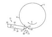
印刷時の両面ドロップアウトの発生を防ぐまたは減らすために、本開示は、DMUに第2計量ブレードを加え、選択的に第2計量ブレードとドラム表面を係合させるために、別個の位置決めシステムとコントロールシステムを設けて、アプリケータによってドラム上に塗付され、第1計量ブレードによって計量されたオイルをさらに計量することを提案する。図11は、両面ドロップアウトを減らすまたは防ぐためのDMUにおける計量ブレードの配置の実施の形態の概略図である。図11の計量ブレードの配置を図2のDMUに用いてもよい。しかし、この計量ブレードの配置をいずれのDMU構成に用いて、アプリケータによってドラム表面上に塗付される剥離剤を計量してもよい。図11に示されるように、第1計量ブレード174および剥離剤アプリケータ104は、図2の計量ブレード174および剥離剤アプリケータ104に対応し、同様に操作することができる。たとえば、図11の剥離剤アプリケータ104にオイルを染み込ませ、ドラム表面に十分なオイルを塗布して、第1計量ブレード174の前にオイルダムを維持して、計量に利用可能な十分な量のオイルを常に確保するように構成される。第1計量ブレード174を用いて、DMUにとって全ての印刷物についてのオイルを計量する。図11の実施の形態では、第1計量ブレード174はドラム表面に関してワイパーモードに配置されるが、他の実施の形態では、第1計量ブレードはドクターモードに配置されてもよい。第1計量ブレード174および剥離剤アプリケータ104は各々、第1計量ブレード174およびアプリケータ104を、ドラム表面14と接触するように、および接触しないように移動させるための位置決めシステム500、504を備える。いずれの好適な位置決めシステムを用いて、第1計量ブレード174および剥離剤アプリケータ104を、ドラム表面と隣接する操作位置へと、および操作位置から離れる位置へとそれぞれ移動させてもよい。たとえば、ある実施の形態では、第1計量ブレード174および剥離剤アプリケータ104についての位置決めシステム500、504は、2つのカムを備える単一カムシャフト(図示せず)を備える。オイルのすじの大きさを最小限にする助けとなるためには、カムは、第1計量ブレード174をアプリケータ104より先に係合させ、すなわちドラム表面14に隣接する位置に移動させ、解除の際には、アプリケータ104を第1計量ブレード174より先にドラム14から離れるように移動させるように構成される。 In order to prevent or reduce the occurrence of double-sided dropout during printing, the present disclosure includes a separate positioning system for adding a second metering blade to the DMU and selectively engaging the second metering blade with the drum surface. It is proposed to provide a control system for further metering the oil applied on the drum by the applicator and metered by the first metering blade. FIG. 11 is a schematic diagram of an embodiment of a metering blade arrangement in a DMU to reduce or prevent double-sided dropout. The metering blade arrangement of FIG. 11 may be used in the DMU of FIG. However, this metering blade arrangement may be used in any DMU configuration to meter the release agent applied onto the drum surface by the applicator. As shown in FIG. 11, the
図11に示されるように、第2計量ブレード510は、ドラム12の回転方向16について、第1計量ブレード174から下流のドラム表面14と係合するように配置され、第1計量ブレード174の後にドラム12の表面14上のオイルを計量する。図11の実施の形態では、第2計量ブレード510は、ドラム表面に関してワイパーモードに配置されるが、他の実施の形態では、第2計量ブレードはドクターモードに配置されてもよい。第2計量ブレード510は、第2計量ブレード510を、第1計量ブレード174から独立してドラム表面14と係合および解除することができる位置決めシステム508を備える。いずれの好適な位置決めシステムを用いてもよい。たとえば、別個のカムシャフトおよびカムを用いて、第2計量ブレードを位置決めしてもよい。場合によっては、第3カムを第1計量ブレードおよびアプリケータのカムシャフトに配置してもよい。 As shown in FIG. 11, the
第2計量ブレード位置決めシステム508はコントローラ80に操作可能に接続され、位置決めシステム508を作動させて、第2計量ブレード510をドラム表面14と係合および解除するように選択的に移動させるように構成される。ある実施の形態では、コントローラ80は、両面印刷物の一方側、たとえば、片面側(すなわち、表面または表面1)または反対面側(すなわち、裏面または表面2)のみについて、第2計量ブレードを作動させてドラム表面上のオイルを計量するように構成される。ある特定の実施の形態では、コントローラ80は、両面印刷毎に両面印刷物の表側印刷時に、第2計量ブレードを作動させてドラム表面上のオイルを計量するように構成される。また別の実施の形態では、コントローラ80は、両面ストレス印刷物の表側印刷のみについて、第2計量ブレード510を作動させるように構成されてもよい。上述のように、両面ストレス印刷物は、表面では高いインク被覆率を有し、裏面では低いインク被覆率を有する。両面ストレス印刷物をいずれの好適な方法で識別してもよい。たとえば、業界で公知であるように、画像源から受け取った画像データに基づいて、両面ストレス印刷物を識別するように、コントローラを構成してもよい。 Second metering
ある実施の形態では、コントローラ80は、第1計量ブレードが「破損」した後に、第2計量ブレード510を作動させはじめるように構成されてもよい。上述のように、ワイパーモードでの単一計量ブレードの場合のオイル使用量は、計量ブレードの磨耗のために、約50,000〜100,000部印刷後では約8〜9mg/シートに増加する。したがって、ある実施の形態では、コントローラ80は、予め定められた部数の印刷(片面または両面)を第1計量ブレード174のみを用いて行った後に、第2計量ブレード510を作動させはじめるように構成される。第2計量ブレードの作動前の第1計量ブレードについての予め定められた印刷部数は、いずれの好適な印刷部数でもよい。ある実施の形態では、コントローラ80は、20,000部の印刷を第1計量ブレードのみを用いて行った後に、第2計量ブレード510を作動させるように構成される。 In certain embodiments, the
第1ワイパーブレードの後に、DMUに第2計量ブレードと、第2計量ブレードを作動させるための対応の位置決めシステムを、両面ストレス印刷物の場合にのみ追加することによって、ストレス両面印刷物の場合のオイル使用量を減らすことができ、両面ドロップアウトを減らしまたは防止することができる。第2計量ブレードの使用を特定のタイプの印刷物、すなわち、両面ストレス印刷物に制限することによって、第2計量ブレードの磨耗を最小限にし、よって、DMU寿命全体にわたって良好な印刷品質を有しながら両面生産性を最大にすることができる。両面ストレス印刷部数は、500,000部印刷のDMUでは5,000程度であってもよい。したがって、第2計量ブレードは約5,000回しか使用されず、第2ブレードを使用した場合に、オイル搬送量が約9mg/シートに対向して、約6mg/シートとなるように磨耗制限を受けてもよい。 Use of oil for stressed duplex prints by adding a second metering blade to the DMU and a corresponding positioning system for operating the second metering blade after the first wiper blade only for duplex stressed prints The amount can be reduced and double-sided dropouts can be reduced or prevented. By restricting the use of the second metering blade to a specific type of print, i.e. double-sided stress print, the wear of the second metering blade is minimized, thus having good print quality over the entire DMU life Productivity can be maximized. The number of double-sided stress printing copies may be about 5,000 in a 500,000-copy DMU. Therefore, the second weighing blade is used only about 5,000 times, and when the second blade is used, the wear limit is set so that the oil conveyance amount is about 6 mg / sheet opposite to about 9 mg / sheet. You may receive it.
図12は図11のDMUを操作する方法のフローチャートを示す。図12に示されるように、印刷ジョブの開始時(ブロック600)、印刷ジョブは両面印刷か否かを決定する(ブロック604)。印刷ジョブが両面印刷でないなら、第1計量ブレードのみを作動させて(ブロック608)、印刷ジョブについてドラム表面上にオイルを計量する。次に、印刷部数(p)が1増加したらコントロールはブロック600に戻る。印刷ジョブが両面印刷の場合には、コントロールはブロック610に進み、この時点で予め定められた印刷部数の閾値を第1計量ブレードを用いて行ったか否かを決定する。上述のように、予め定められた印刷部数は約20,000印刷部であってもよいが、いずれの好適な印刷部数を閾値として用いてもよい。印刷部数(p)が閾値より大きくない場合には、第1計量ブレードのみを作動させて(ブロック608)、印刷ジョブについてドラム表面上にオイルを計量し、印刷部数(p)が1増加したらコントロールはブロック600に戻る。印刷部数(p)が閾値より大きい場合には、どちらの面を今回印刷するかを決定する(ブロック614)。表面1(たとえば、表面または片面)を印刷する場合には、第1および第2計量ブレードを作動させて(ブロック618)、両面印刷の表面1の印刷についてドラム表面上にオイルを計量し、印刷部数(p)が1増加したらコントロールはブロック600に戻る。表面2を印刷する場合には、第1計量ブレードのみを作動させて(ブロック608)、印刷ジョブについてドラム表面上にオイルを計量し、印刷部数(p)が1増加したらコントロールはブロック600に戻る。 FIG. 12 shows a flowchart of a method for operating the DMU of FIG. As shown in FIG. 12, at the start of a print job (block 600), it is determined whether the print job is duplex printing (block 604). If the print job is not duplex, only the first metering blade is activated (block 608) to meter oil on the drum surface for the print job. Next, if the number of copies (p) is increased by 1, control returns to block 600. If the print job is duplex printing, control proceeds to block 610 where it determines whether a predetermined number of copies has been thresholded using the first metering blade at this point. As described above, the predetermined number of printed copies may be about 20,000 printed copies, but any suitable number of printed copies may be used as a threshold value. If the number of copies to print (p) is not greater than the threshold, only the first metering blade is activated (block 608) and the oil is metered on the drum surface for the print job, and the control is performed when the number of copies to print (p) increases by one. Returns to block 600. If the number of copies (p) is greater than the threshold, it is determined which side is to be printed this time (block 614). When printing surface 1 (eg, surface or single side), the first and second metering blades are actuated (block 618) to meter oil on the drum surface for printing on
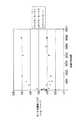
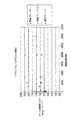
アプリケータ、第1計量ブレードおよび第2計量ブレードの作動についてのタイミングシーケンスの実施の形態を図13に示す。図13では、高い値は、アプリケータ、第1計量ブレードおよび第2計量ブレードが係合状態にある、たとえば、ドラム表面との操作可能位置にある時間に対応し、低い値は、アプリケータ、第1計量ブレードおよび第2計量ブレードが係合状態にない、たとえば、ドラム表面との操作可能位置にない時間に対応する。図13に示されるように、第1計量ブレードが始めに、次いでアプリケータがドラム表面と係合するように移動する。そして、第2計量ブレードがアプリケータの後にドラム表面と係合するように移動する。解除時、第2計量ブレードが、次いでアプリケータ、そして第1計量ブレードがドラム表面と係合解除するように移動する。図13のタイミングシーケンスは、ドラムへのオイル運搬をさらに減らすために、オイルのすじの大きさを制限している。 An embodiment of a timing sequence for the operation of the applicator, the first metering blade and the second metering blade is shown in FIG. In FIG. 13, a high value corresponds to the time when the applicator, the first metering blade and the second metering blade are in engagement, for example in an operable position with the drum surface, and a low value is the applicator, This corresponds to a time when the first metering blade and the second metering blade are not in an engaged state, for example, not in an operable position with the drum surface. As shown in FIG. 13, the first metering blade is moved first so that the applicator engages the drum surface. The second metering blade then moves to engage the drum surface after the applicator. Upon release, the second metering blade is then moved so that the applicator and then the first metering blade disengage from the drum surface. The timing sequence of FIG. 13 limits the size of the oil streaks to further reduce oil transport to the drum.
10 画像形成装置、14 画像受容表面、32,34 プリントヘッドアセンブリ、100 ドラムメンテナンスユニット、104 アプリケータ、108 リザーバ、174 第1計量ブレード、500 第1計量ブレード位置決めシステム、508 第2計量ブレード位置決めシステム、510 第2計量ブレード、CP クロス処理方向。 DESCRIPTION OF SYMBOLS 10 Image forming apparatus, 14 Image receiving surface, 32, 34 Print head assembly, 100 Drum maintenance unit, 104 Applicator, 108 Reservoir, 174 First metering blade, 500 First metering blade positioning system, 508 Second metering blade positioning system , 510 Second metering blade, CP cross processing direction.
Claims (4)
Translated fromJapaneseリザーバから剥離剤を受け取り、剥離剤を、処理方向に移動する画像形成装置の中間画像形成表面に塗布するように構成されるアプリケータと、
中間画像形成表面に隣接して、第1位置にワイパーモードで配置され、アプリケータによって塗付された中間画像形成表面上の剥離剤を計量するように構成される第1計量ブレードと、
中間画像形成表面に隣接して、第2位置にワイパーモードで配置される第2計量ブレードと、
第2計量ブレードに操作可能に接続され、両面印刷ジョブの第1の側を印刷する際には、アプリケータによって中間画像形成表面に塗付された剥離剤をさらに計量するために、中間画像形成表面と係合するように第2計量ブレードを移動させ、片面印刷ジョブを印刷する際および両面印刷ジョブの第2面を印刷する際には、中間画像形成表面と係合解除するように第2計量ブレードを移動させるよう構成される第2計量ブレード位置決めシステムと
を備える画像形成装置に使用するドラムメンテナンスシステム。A reservoir for supplying a release agent;
An applicator configured to receive a release agent from a reservoir and apply the release agent to an intermediate imaging surface of an imaging device moving in a processing direction;
A first metering blade disposed in a wiper mode at a first position adjacent to the intermediate imaging surface and configured to meter release agent on the intermediate imaging surface applied by the applicator;
A second metering blade disposed in a wiper mode at a second position adjacent to the intermediate imaging surface;
Intermediate printing to further meter the release agent applied to the intermediate imaging surface by the applicator when operably connected to the second metering blade and printing the first side of a duplex printing job The second metering blade is moved to engage the surface, and when printing a single-sided print job and printing the second side of a double-sided print job, the second metering blade is disengaged from the intermediate imaging surface. A drum maintenance system for use in an image forming apparatus, comprising: a second metering blade positioning system configured to move the metering blade.
第2計量ブレード位置決めシステムは、予め定められた部数の印刷物を第1計量ブレードのみを用いて印刷した後に、第2計量ブレードを中間画像形成表面と係合するように、および係合解除するように移動させはじめるよう構成されるシステム。The system of claim 1, wherein
The second metering blade positioning system is configured to engage and disengage the second metering blade with the intermediate imaging surface after printing a predetermined number of copies using only the first metering blade. A system that is configured to begin moving.
第1計量ブレードに操作可能に接続され、アプリケータによって中間画像形成表面に塗付された剥離剤を計量するために、何れかの印刷ジョブの一方面を印刷する際には、中間画像形成表面と係合するように第1計量ブレードを移動させ、何れかの印刷ジョブの一方側印刷後には、中間画像形成表面と係合解除するように、第1計量ブレードを移動させるよう構成される第1計量ブレード位置決めシステムをさらに備える請求項1のシステム。The system of claim 1, wherein
When printing one side of any print job to meter release agent that is operably connected to the first metering blade and applied to the intermediate imaging surface by the applicator, the intermediate imaging surface A first metering blade configured to move the first metering blade to disengage from the intermediate imaging surface after printing on one side of any print job. The system of claim 1 further comprising a one metering blade positioning system.
溶融した相転移インクを中間画像形成表面上に噴出するように構成される少なくとも1つのプリントヘッドと、
ドラムメンテナンスユニットとを備え、
ドラムメンテナンスユニットは、
剥離剤を供給するリザーバと、
リザーバから剥離剤を受け取り、剥離剤を中間画像形成表面に塗布するように構成されるアプリケータと、
中間画像形成表面に隣接して、第1位置にワイパーモードで配置され、アプリケータによって塗付された中間画像形成表面上の剥離剤を計量するように構成される第1計量ブレードと、
中間画像形成表面に隣接して、第2位置にワイパーモードで配置される第2計量ブレードと、
第2計量ブレードに操作可能に接続され、両面印刷ジョブの第1面を印刷する際には、アプリケータによって中間画像形成表面に塗付された剥離剤をさらに計量するために、中間画像形成表面と係合するように第2計量ブレードを移動させ、片面印刷ジョブを印刷する際および両面印刷ジョブの第2面を印刷する際には、中間画像形成表面と係合解除するように、第2計量ブレードを移動させるよう構成される第2計量ブレード位置決めシステムと
を含む相転移インク画像形成装置。An intermediate imaging surface configured to move in a processing direction;
At least one printhead configured to eject molten phase change ink onto the intermediate imaging surface;
A drum maintenance unit,
The drum maintenance unit
A reservoir for supplying a release agent;
An applicator configured to receive the release agent from the reservoir and apply the release agent to the intermediate imaging surface;
A first metering blade disposed in a wiper mode at a first position adjacent to the intermediate imaging surface and configured to meter release agent on the intermediate imaging surface applied by the applicator;
A second metering blade disposed in a wiper mode at a second position adjacent to the intermediate imaging surface;
The intermediate imaging surface is further operatively connected to the second metering blade to further weigh the release agent applied to the intermediate imaging surface by the applicator when printing the first side of a duplex printing job. The second metering blade is moved to engage with the second imaging blade so as to disengage from the intermediate imaging surface when printing a single-sided printing job and when printing the second side of a double-sided printing job. And a second metering blade positioning system configured to move the metering blade.
Applications Claiming Priority (2)
| Application Number | Priority Date | Filing Date | Title |
|---|---|---|---|
| US12/535,064 | 2009-08-04 | ||
| US12/535,064US8177352B2 (en) | 2009-08-04 | 2009-08-04 | Drum maintenance system for reducing duplex dropout |
Publications (2)
| Publication Number | Publication Date |
|---|---|
| JP2011031619Atrue JP2011031619A (en) | 2011-02-17 |
| JP5364657B2 JP5364657B2 (en) | 2013-12-11 |
Family
ID=42827516
Family Applications (1)
| Application Number | Title | Priority Date | Filing Date |
|---|---|---|---|
| JP2010174436AExpired - Fee RelatedJP5364657B2 (en) | 2009-08-04 | 2010-08-03 | Drum maintenance system to reduce double-sided dropout |
Country Status (7)
| Country | Link |
|---|---|
| US (1) | US8177352B2 (en) |
| EP (1) | EP2281689B1 (en) |
| JP (1) | JP5364657B2 (en) |
| KR (1) | KR101234481B1 (en) |
| CN (1) | CN101992590B (en) |
| BR (1) | BRPI1002957A2 (en) |
| MX (1) | MX2010008232A (en) |
Cited By (27)
| Publication number | Priority date | Publication date | Assignee | Title |
|---|---|---|---|---|
| JP2019525966A (en)* | 2016-05-30 | 2019-09-12 | ランダ コーポレイション リミテッド | Digital printing process |
| US11179928B2 (en) | 2015-04-14 | 2021-11-23 | Landa Corporation Ltd. | Indirect printing system and related apparatus |
| US11203199B2 (en) | 2016-05-30 | 2021-12-21 | Landa Corporation Ltd. | Digital printing process and system |
| US11235568B2 (en) | 2015-03-20 | 2022-02-01 | Landa Corporation Ltd. | Indirect printing system |
| US11285715B2 (en) | 2012-03-15 | 2022-03-29 | Landa Corporation Ltd. | Endless flexible belt for a printing system |
| US11321028B2 (en) | 2019-12-11 | 2022-05-03 | Landa Corporation Ltd. | Correcting registration errors in digital printing |
| US11318734B2 (en) | 2018-10-08 | 2022-05-03 | Landa Corporation Ltd. | Friction reduction means for printing systems and method |
| US11327413B2 (en) | 2016-05-30 | 2022-05-10 | Landa Corporation Ltd. | Intermediate transfer member |
| US11465426B2 (en) | 2018-06-26 | 2022-10-11 | Landa Corporation Ltd. | Intermediate transfer member for a digital printing system |
| US11511536B2 (en) | 2017-11-27 | 2022-11-29 | Landa Corporation Ltd. | Calibration of runout error in a digital printing system |
| US11548275B2 (en) | 2018-08-02 | 2023-01-10 | Landa Corporation Ltd. | Digital printing system with flexible intermediate transfer member |
| US11559982B2 (en) | 2012-03-05 | 2023-01-24 | Landa Corporation Ltd. | Digital printing process |
| US11607878B2 (en) | 2012-03-05 | 2023-03-21 | Landa Corporation Ltd. | Digital printing system |
| US11655382B2 (en) | 2013-09-11 | 2023-05-23 | Landa Corporation Ltd. | Ink formulations and film constructions thereof |
| US11660856B2 (en) | 2017-11-19 | 2023-05-30 | Landa Corporation Ltd. | Digital printing system |
| US11679615B2 (en) | 2017-12-07 | 2023-06-20 | Landa Corporation Ltd. | Digital printing process and method |
| US11707943B2 (en) | 2017-12-06 | 2023-07-25 | Landa Corporation Ltd. | Method and apparatus for digital printing |
| US11713399B2 (en) | 2012-03-05 | 2023-08-01 | Landa Corporation Ltd. | Ink film constructions |
| US11724487B2 (en) | 2012-03-05 | 2023-08-15 | Landa Corporation Ltd. | Apparatus and method for control or monitoring a printing system |
| US11787170B2 (en) | 2018-12-24 | 2023-10-17 | Landa Corporation Ltd. | Digital printing system |
| US11809100B2 (en) | 2012-03-05 | 2023-11-07 | Landa Corporation Ltd. | Intermediate transfer members for use with indirect printing systems and protonatable intermediate transfer members for use with indirect printing systems |
| US11833813B2 (en) | 2019-11-25 | 2023-12-05 | Landa Corporation Ltd. | Drying ink in digital printing using infrared radiation |
| US11884089B2 (en) | 2012-03-05 | 2024-01-30 | Landa Corporation Ltd. | Printing system |
| US12001902B2 (en) | 2018-08-13 | 2024-06-04 | Landa Corporation Ltd. | Correcting distortions in digital printing by implanting dummy pixels in a digital image |
| US12011920B2 (en) | 2019-12-29 | 2024-06-18 | Landa Corporation Ltd. | Printing method and system |
| US12358277B2 (en) | 2019-03-31 | 2025-07-15 | Landa Corporation Ltd. | Systems and methods for preventing or minimizing printing defects in printing processes |
| US12430453B2 (en) | 2021-02-02 | 2025-09-30 | Landa Corporation Ltd. | Mitigating distortions in printed images |
Families Citing this family (6)
| Publication number | Priority date | Publication date | Assignee | Title |
|---|---|---|---|---|
| US8074809B2 (en)* | 2009-07-17 | 2011-12-13 | Gordon H. King | Apparatus and method for the treatment of liquid/solid mixtures |
| US20110032306A1 (en)* | 2009-08-04 | 2011-02-10 | Xerox Corporation | System for Reducing Metering Blade Wear in a Drum Maintenance Unit |
| CN102529350B (en)* | 2010-11-24 | 2014-10-22 | 精工爱普生株式会社 | Ink jet printing apparatus and method of manufacturing printed goods using ink jet printing apparatus |
| US8485621B2 (en)* | 2011-03-09 | 2013-07-16 | Xerox Corporation | Solid inkjet drum maintenance unit (DMU) employing adjustable blade cam in order to control the oil rate |
| US8727518B2 (en) | 2012-06-11 | 2014-05-20 | Xerox Corporation | Method for positioning a metering blade with reference to roller and blade wear |
| US9022548B2 (en)* | 2013-07-16 | 2015-05-05 | Xerox Corporation | System and method for monitoring the application of release agent in an inkjet printer |
Citations (3)
| Publication number | Priority date | Publication date | Assignee | Title |
|---|---|---|---|---|
| JP2005153524A (en)* | 2003-11-21 | 2005-06-16 | Xerox Corp | Applicator assembly having foam oil donor roll and method of controlling oil level |
| JP2008030430A (en)* | 2006-06-28 | 2008-02-14 | Fuji Xerox Co Ltd | Liquid droplet ejection apparatus |
| JP2008055837A (en)* | 2006-09-01 | 2008-03-13 | Fuji Xerox Co Ltd | Droplet ejection apparatus |
Family Cites Families (14)
| Publication number | Priority date | Publication date | Assignee | Title |
|---|---|---|---|---|
| US6016409A (en) | 1997-04-11 | 2000-01-18 | Xerox Corporation | System for managing fuser modules in a digital printing apparatus |
| US5937257A (en) | 1998-01-08 | 1999-08-10 | Xerox Corporation | Retractable oil reducing metering blade |
| US6196675B1 (en)* | 1998-02-25 | 2001-03-06 | Xerox Corporation | Apparatus and method for image fusing |
| JP2001216991A (en)* | 2000-02-02 | 2001-08-10 | Toyota Motor Corp | Fuel cell performance evaluation device and its evaluation method, specific surface area evaluation device for fuel cell electrode catalyst and its evaluation method, and fuel cell electrode catalyst and its manufacturing method |
| US6955721B2 (en)* | 2002-02-28 | 2005-10-18 | Lexmark International, Inc. | System and method of coating print media in an inkjet printer |
| JP2004045668A (en)* | 2002-07-10 | 2004-02-12 | Ricoh Co Ltd | Developer for developing electrostatic image, image forming apparatus, and image forming method |
| US7048369B2 (en)* | 2003-12-22 | 2006-05-23 | Xerox Corporation | Electrostatic grounding for drum maintenance unit |
| US7393312B2 (en) | 2003-12-22 | 2008-07-01 | Xerox Corporation | Oiling roller assembly for a drum maintenance unit |
| US7036920B2 (en) | 2003-12-22 | 2006-05-02 | Xerox Corporation | Filtering of ink debris in reclaimed liquid in an imaging device |
| US6921064B2 (en) | 2003-12-22 | 2005-07-26 | Xerox Corporation | Metering blade suspension system |
| US7699459B2 (en)* | 2005-12-23 | 2010-04-20 | Xerox Corporation | Drum maintenance system for an imaging device and method and system for maintaining an imaging device |
| JP2007177333A (en)* | 2005-12-26 | 2007-07-12 | Fuji Xerox Co Ltd | recoding media |
| US7708377B2 (en) | 2008-08-29 | 2010-05-04 | Xerox Corporation | Blade engagement apparatus for image forming machines |
| US8087771B2 (en) | 2008-08-29 | 2012-01-03 | Xerox Corporation | Dual blade release agent application apparatus |
- 2009
- 2009-08-04USUS12/535,064patent/US8177352B2/ennot_activeExpired - Fee Related
- 2010
- 2010-07-28MXMX2010008232Apatent/MX2010008232A/enactiveIP Right Grant
- 2010-07-30CNCN201010246612.0Apatent/CN101992590B/ennot_activeExpired - Fee Related
- 2010-08-02KRKR1020100074535Apatent/KR101234481B1/ennot_activeExpired - Fee Related
- 2010-08-03BRBRPI1002957-5Apatent/BRPI1002957A2/ennot_activeIP Right Cessation
- 2010-08-03EPEP10171693Apatent/EP2281689B1/ennot_activeNot-in-force
- 2010-08-03JPJP2010174436Apatent/JP5364657B2/ennot_activeExpired - Fee Related
Patent Citations (3)
| Publication number | Priority date | Publication date | Assignee | Title |
|---|---|---|---|---|
| JP2005153524A (en)* | 2003-11-21 | 2005-06-16 | Xerox Corp | Applicator assembly having foam oil donor roll and method of controlling oil level |
| JP2008030430A (en)* | 2006-06-28 | 2008-02-14 | Fuji Xerox Co Ltd | Liquid droplet ejection apparatus |
| JP2008055837A (en)* | 2006-09-01 | 2008-03-13 | Fuji Xerox Co Ltd | Droplet ejection apparatus |
Cited By (30)
| Publication number | Priority date | Publication date | Assignee | Title |
|---|---|---|---|---|
| US11559982B2 (en) | 2012-03-05 | 2023-01-24 | Landa Corporation Ltd. | Digital printing process |
| US11884089B2 (en) | 2012-03-05 | 2024-01-30 | Landa Corporation Ltd. | Printing system |
| US11809100B2 (en) | 2012-03-05 | 2023-11-07 | Landa Corporation Ltd. | Intermediate transfer members for use with indirect printing systems and protonatable intermediate transfer members for use with indirect printing systems |
| US11724487B2 (en) | 2012-03-05 | 2023-08-15 | Landa Corporation Ltd. | Apparatus and method for control or monitoring a printing system |
| US11713399B2 (en) | 2012-03-05 | 2023-08-01 | Landa Corporation Ltd. | Ink film constructions |
| US11607878B2 (en) | 2012-03-05 | 2023-03-21 | Landa Corporation Ltd. | Digital printing system |
| US11285715B2 (en) | 2012-03-15 | 2022-03-29 | Landa Corporation Ltd. | Endless flexible belt for a printing system |
| US11655382B2 (en) | 2013-09-11 | 2023-05-23 | Landa Corporation Ltd. | Ink formulations and film constructions thereof |
| US11235568B2 (en) | 2015-03-20 | 2022-02-01 | Landa Corporation Ltd. | Indirect printing system |
| US11179928B2 (en) | 2015-04-14 | 2021-11-23 | Landa Corporation Ltd. | Indirect printing system and related apparatus |
| US11327413B2 (en) | 2016-05-30 | 2022-05-10 | Landa Corporation Ltd. | Intermediate transfer member |
| JP2019525966A (en)* | 2016-05-30 | 2019-09-12 | ランダ コーポレイション リミテッド | Digital printing process |
| US11203199B2 (en) | 2016-05-30 | 2021-12-21 | Landa Corporation Ltd. | Digital printing process and system |
| US11396190B2 (en) | 2016-05-30 | 2022-07-26 | Landa Corporation Ltd. | Digital printing process |
| JP7144328B2 (en) | 2016-05-30 | 2022-09-29 | ランダ コーポレイション リミテッド | digital printing process |
| US11660856B2 (en) | 2017-11-19 | 2023-05-30 | Landa Corporation Ltd. | Digital printing system |
| JP2024079796A (en)* | 2017-11-19 | 2024-06-11 | ランダ コーポレイション リミテッド | Digital Printing System |
| US11511536B2 (en) | 2017-11-27 | 2022-11-29 | Landa Corporation Ltd. | Calibration of runout error in a digital printing system |
| US11707943B2 (en) | 2017-12-06 | 2023-07-25 | Landa Corporation Ltd. | Method and apparatus for digital printing |
| US11679615B2 (en) | 2017-12-07 | 2023-06-20 | Landa Corporation Ltd. | Digital printing process and method |
| US11465426B2 (en) | 2018-06-26 | 2022-10-11 | Landa Corporation Ltd. | Intermediate transfer member for a digital printing system |
| US11548275B2 (en) | 2018-08-02 | 2023-01-10 | Landa Corporation Ltd. | Digital printing system with flexible intermediate transfer member |
| US12001902B2 (en) | 2018-08-13 | 2024-06-04 | Landa Corporation Ltd. | Correcting distortions in digital printing by implanting dummy pixels in a digital image |
| US11318734B2 (en) | 2018-10-08 | 2022-05-03 | Landa Corporation Ltd. | Friction reduction means for printing systems and method |
| US11787170B2 (en) | 2018-12-24 | 2023-10-17 | Landa Corporation Ltd. | Digital printing system |
| US12358277B2 (en) | 2019-03-31 | 2025-07-15 | Landa Corporation Ltd. | Systems and methods for preventing or minimizing printing defects in printing processes |
| US11833813B2 (en) | 2019-11-25 | 2023-12-05 | Landa Corporation Ltd. | Drying ink in digital printing using infrared radiation |
| US11321028B2 (en) | 2019-12-11 | 2022-05-03 | Landa Corporation Ltd. | Correcting registration errors in digital printing |
| US12011920B2 (en) | 2019-12-29 | 2024-06-18 | Landa Corporation Ltd. | Printing method and system |
| US12430453B2 (en) | 2021-02-02 | 2025-09-30 | Landa Corporation Ltd. | Mitigating distortions in printed images |
Also Published As
| Publication number | Publication date |
|---|---|
| CN101992590A (en) | 2011-03-30 |
| MX2010008232A (en) | 2011-02-21 |
| EP2281689B1 (en) | 2012-06-20 |
| KR101234481B1 (en) | 2013-02-18 |
| BRPI1002957A2 (en) | 2012-04-10 |
| EP2281689A1 (en) | 2011-02-09 |
| US20110032288A1 (en) | 2011-02-10 |
| US8177352B2 (en) | 2012-05-15 |
| KR20110014108A (en) | 2011-02-10 |
| CN101992590B (en) | 2013-03-13 |
| JP5364657B2 (en) | 2013-12-11 |
Similar Documents
| Publication | Publication Date | Title |
|---|---|---|
| JP5364657B2 (en) | Drum maintenance system to reduce double-sided dropout | |
| JP5349418B2 (en) | Image forming apparatus and customer replacement unit | |
| JP2011031618A (en) | System for reducing abrasion of metering blade in drum maintenance unit | |
| US8573721B2 (en) | Method of increasing the life of a drum maintenance unit in a printer | |
| JP5879929B2 (en) | Treatment liquid coating apparatus for inkjet printer, operating method of the coating apparatus, and image forming system | |
| US9162465B1 (en) | Method and apparatus to clean printheads in an inkjet printer | |
| JP5031630B2 (en) | Coating liquid supply apparatus and inkjet recording apparatus | |
| CN1654209A (en) | Liquid applying apparatus and ink jet printing apparatus | |
| US8684494B2 (en) | Fluid applicator for a printhead face | |
| US8322842B2 (en) | Gel maintenance cycle for a release agent application system | |
| US8303103B2 (en) | Peak position drum maintenance unit for a printing device | |
| US20140292916A1 (en) | Head cleaning method and liquid discharging apparatus | |
| JP2004009689A (en) | Ink jet printer | |
| US9061514B2 (en) | Release agent applicator system with replaceable reservoir pad | |
| US8662658B2 (en) | Printer having drum maintenance unit architecture for controlled application of a release agent | |
| US8714730B2 (en) | Method of selective drum maintenance in a drum maintenance unit in a printing apparatus | |
| JP2020199710A (en) | Cleaning device, inkjet image formation device and cleaning method |
Legal Events
| Date | Code | Title | Description |
|---|---|---|---|
| A621 | Written request for application examination | Free format text:JAPANESE INTERMEDIATE CODE: A621 Effective date:20130801 | |
| A871 | Explanation of circumstances concerning accelerated examination | Free format text:JAPANESE INTERMEDIATE CODE: A871 Effective date:20130801 | |
| TRDD | Decision of grant or rejection written | ||
| A01 | Written decision to grant a patent or to grant a registration (utility model) | Free format text:JAPANESE INTERMEDIATE CODE: A01 Effective date:20130827 | |
| A61 | First payment of annual fees (during grant procedure) | Free format text:JAPANESE INTERMEDIATE CODE: A61 Effective date:20130909 | |
| R150 | Certificate of patent or registration of utility model | Ref document number:5364657 Country of ref document:JP Free format text:JAPANESE INTERMEDIATE CODE: R150 Free format text:JAPANESE INTERMEDIATE CODE: R150 | |
| R250 | Receipt of annual fees | Free format text:JAPANESE INTERMEDIATE CODE: R250 | |
| R250 | Receipt of annual fees | Free format text:JAPANESE INTERMEDIATE CODE: R250 | |
| R250 | Receipt of annual fees | Free format text:JAPANESE INTERMEDIATE CODE: R250 | |
| LAPS | Cancellation because of no payment of annual fees |