JP2011027724A - Three-dimensional measurement apparatus, measurement method therefor, and program - Google Patents
Three-dimensional measurement apparatus, measurement method therefor, and programDownload PDFInfo
- Publication number
- JP2011027724A JP2011027724AJP2010137680AJP2010137680AJP2011027724AJP 2011027724 AJP2011027724 AJP 2011027724AJP 2010137680 AJP2010137680 AJP 2010137680AJP 2010137680 AJP2010137680 AJP 2010137680AJP 2011027724 AJP2011027724 AJP 2011027724A
- Authority
- JP
- Japan
- Prior art keywords
- distance
- measurement
- target object
- image
- measurement target
- Prior art date
- Legal status (The legal status is an assumption and is not a legal conclusion. Google has not performed a legal analysis and makes no representation as to the accuracy of the status listed.)
- Granted
Links
Images


Classifications
- G—PHYSICS
- G01—MEASURING; TESTING
- G01B—MEASURING LENGTH, THICKNESS OR SIMILAR LINEAR DIMENSIONS; MEASURING ANGLES; MEASURING AREAS; MEASURING IRREGULARITIES OF SURFACES OR CONTOURS
- G01B11/00—Measuring arrangements characterised by the use of optical techniques
- G01B11/24—Measuring arrangements characterised by the use of optical techniques for measuring contours or curvatures
- G01B11/25—Measuring arrangements characterised by the use of optical techniques for measuring contours or curvatures by projecting a pattern, e.g. one or more lines, moiré fringes on the object
- G—PHYSICS
- G06—COMPUTING OR CALCULATING; COUNTING
- G06T—IMAGE DATA PROCESSING OR GENERATION, IN GENERAL
- G06T7/00—Image analysis
- G06T7/50—Depth or shape recovery
- G06T7/521—Depth or shape recovery from laser ranging, e.g. using interferometry; from the projection of structured light
Landscapes
- Engineering & Computer Science (AREA)
- Physics & Mathematics (AREA)
- Computer Vision & Pattern Recognition (AREA)
- General Physics & Mathematics (AREA)
- Optics & Photonics (AREA)
- Theoretical Computer Science (AREA)
- Length Measuring Devices By Optical Means (AREA)
Abstract
Translated fromJapaneseDescription
Translated fromJapanese本発明は、3次元計測装置、その計測方法及びプログラムに関する。 The present invention relates to a three-dimensional measuring apparatus, a measuring method thereof, and a program.
近年、これまで人間が行なっていた複雑なタスクをロボットが代わりに行なうようになりつつある。複雑なタスクの代表例として、工業製品の組み立てが挙げられる。ここで、例えば、ロボットにおいて、ハンドなどのエンドエフェクタによって部品を把持する際には、部品とロボット(ハンド)との間の相対的な位置及び姿勢を計測し、その計測結果に基づいて移動計画を策定し、アクチュエータを制御する必要がある。このような位置及び姿勢の計測は、ロボットによる部品把持だけでなく、ロボットが自律移動する際の自己位置推定など様々な場面で必要とされている。 In recent years, robots are beginning to perform complex tasks that have been performed by humans instead. A typical example of a complex task is assembly of industrial products. Here, for example, when a part is gripped by an end effector such as a hand in a robot, the relative position and orientation between the part and the robot (hand) are measured, and a movement plan is based on the measurement result. It is necessary to formulate and control the actuator. Such measurement of position and orientation is required not only for gripping parts by the robot but also for various situations such as self-position estimation when the robot moves autonomously.
上述した位置及び姿勢の計測では、カメラから得られる2次元画像(濃淡画像・カラー画像)や距離センサから得られる距離画像が用いられる。非特許文献1では、物体の3次元形状モデルを線分の集合(ワイヤフレームモデル)で表し、2次元画像上で検出されるエッジに3次元の線分の投影像を当てはめることにより、物体の位置及び姿勢を計測する技術について言及されている。また、非特許文献2では、距離画像から得られる物体表面上の3次元点群に物体の3次元形状モデル(ポリゴンモデル)を当てはめることにより、物体の位置及び姿勢を計測する技術がについて言及されている。 In the position and orientation measurement described above, a two-dimensional image (grayscale image / color image) obtained from a camera or a distance image obtained from a distance sensor is used. In Non-Patent
距離画像を取得する方法としては、特別な照明を必要としないパッシブ計測と、計測のために特別なパターンを照射するアクティブ計測とが知られている。パッシブ計測では、一般に、2台以上のカメラによって物体を撮像し、それぞれの画像間の対応をもとに三角測量の原理に基づいて各画素の距離を算出する。アクティブ計測では、一般に、スリット光や2次元パターン光などを物体に照射し、三角測量の原理に基づいて距離の計測を行なう。また、アクティブ計測として、照射した光が物体上から反射して戻ってくるまでの時間を利用するTime−of−Flight(TOF)方式も知られている。 As a method of acquiring a distance image, passive measurement that does not require special illumination and active measurement that irradiates a special pattern for measurement are known. In passive measurement, generally, an object is imaged by two or more cameras, and the distance of each pixel is calculated based on the principle of triangulation based on the correspondence between the images. In active measurement, generally, an object is irradiated with slit light, two-dimensional pattern light, or the like, and a distance is measured based on the principle of triangulation. In addition, as an active measurement, a Time-of-Flight (TOF) method that uses time until irradiated light is reflected from an object and returned is also known.
さて、2次元画像を利用した位置及び姿勢の計測では、画像特徴と3次元形状モデルの投影像との”2次元画像上における”距離を最小化することにより計測が行なわれる。そのため、計測精度は必ずしも高いとはいえず、特に、カメラの奥行き方向の位置成分については精度が低い。一方、距離画像を利用した位置及び姿勢の計測では、3次元点群と3次元形状モデルの”3次元空間内における”距離を最小化することにより計測が行なわれる。そのため、2次元画像を利用する手法に比べて計測精度は高くなるが、物体(例えば、平面状の物体)の形状があまり特徴的でなければ、一部の自由度を精度良く計測できない。 In the measurement of the position and orientation using a two-dimensional image, the measurement is performed by minimizing the distance “on the two-dimensional image” between the image feature and the projection image of the three-dimensional shape model. Therefore, the measurement accuracy is not necessarily high, and the accuracy is particularly low for the position component in the depth direction of the camera. On the other hand, in the position and orientation measurement using the distance image, the measurement is performed by minimizing the distance “in the three-dimensional space” between the three-dimensional point group and the three-dimensional shape model. Therefore, although the measurement accuracy is higher than the method using a two-dimensional image, if the shape of an object (for example, a planar object) is not very characteristic, some degrees of freedom cannot be measured with high accuracy.
そこで、2次元画像と距離画像とを相補的に利用して位置及び姿勢の計測精度を向上させることが望まれている。例えば、背景と物体との境界や面の切り替わりなど濃淡変化が激しい部分においては2次元画像上でエッジ(画像特徴)を多く検出できるため、2次元画像を用いれば良い。一方、画像特徴が検出され難い平坦な部分では距離を安定的に計測できるため、距離画像を用いれば良い。 Therefore, it is desired to improve the measurement accuracy of the position and orientation by using the two-dimensional image and the distance image in a complementary manner. For example, since a large number of edges (image features) can be detected on a two-dimensional image in a portion where the change in shading is strong, such as a boundary between a background and an object or a change of surface, a two-dimensional image may be used. On the other hand, a distance image may be used because a distance can be stably measured in a flat portion where an image feature is difficult to detect.
このような技術に関連して、非特許文献3では、2次元画像上の特徴を奥行きが不定な3次元の点として扱い、物体の位置及び姿勢を計測する手法が開示されている。また、非特許文献4では、2次元画像から明示的な特徴検出は行なわず、2次元の濃淡画像と距離画像との勾配情報を利用して位置及び姿勢を計測する手法が開示されている。 In relation to such a technique, Non-Patent Document 3 discloses a method of measuring the position and orientation of an object by treating features on a two-dimensional image as a three-dimensional point having an indefinite depth. Non-Patent Document 4 discloses a method of measuring position and orientation using gradient information between a two-dimensional grayscale image and a distance image without performing explicit feature detection from the two-dimensional image.
ロボットを用いて工業製品の組み立てを行なうことにより、組み立て作業の高速化が期待されている。例えば、ベルトコンベアーによって移動している物体の位置及び姿勢を計測したり、ロボットアーム上に計測装置を設置して当該装置を移動させながら物体の位置及び姿勢を計測したりすることが求められている。 The assembly work is expected to be speeded up by assembling industrial products using a robot. For example, it is required to measure the position and orientation of an object moving by a belt conveyor, or to measure the position and orientation of an object while moving the device by installing a measuring device on a robot arm. Yes.
カメラやプロジェクターなどの単純な機器構成では、特別なパターンが照射されていない状態で撮像した画像と、距離計測用パターンが照射された状態で撮像した画像とを異なるタイミングで取得しなければならない。計測対象物体と計測装置とが相対的に静止していれば、これら2種類の画像が異なるタイミングで取得されても問題はない。 In a simple device configuration such as a camera or a projector, an image captured in a state where a special pattern is not irradiated and an image captured in a state where a distance measurement pattern is irradiated must be acquired at different timings. If the measurement target object and the measurement apparatus are relatively stationary, there is no problem even if these two types of images are acquired at different timings.
しかし、計測対象物体又は計測装置自体が移動している場合に、これら2種類の画像が異なるタイミングで取得されたときには、2次元画像の取得時と距離画像の取得時における計測対象物体と計測装置との間の相対的な位置関係が変わってしまう。そのため、このような場合には、物体の位置及び姿勢の計測を精度良く行なうことができない。 However, when the measurement target object or the measurement apparatus itself is moving and the two types of images are acquired at different timings, the measurement target object and the measurement apparatus at the time of acquiring the two-dimensional image and the distance image are acquired. The relative positional relationship between and will change. Therefore, in such a case, the position and orientation of the object cannot be accurately measured.
本発明は、上記課題に鑑みてなされたものであり、3次元計測装置と計測対象物体との間の位置及び姿勢の関係が高速に変化している場合であっても、装置構成を複雑化させずに、当該物体の位置及び姿勢の計測を精度良く行なえるようにした技術を提供する。 The present invention has been made in view of the above problems, and complicates the apparatus configuration even when the position and orientation relationship between the three-dimensional measurement apparatus and the measurement target object is changing at high speed. Therefore, there is provided a technique capable of measuring the position and orientation of the object with high accuracy without doing so.
上記課題を解決するため、本発明の一態様による3次元計測装置は、計測対象物体の3次元形状モデルを保持するモデル保持手段と、前記計測対象物体の3次元形状を示す情報に基づいて前記計測対象物体における距離計測用の領域を決定する決定手段と、前記計測対象物体に対して所定の照明パターンを照射する照明手段と、前記照明手段による照射が行なわれている状態で前記計測対象物体の画像を撮像する撮像手段と、前記撮像された画像内における前記距離計測用の領域に対応する領域に基づいて前記撮像手段から前記計測対象物体までの距離を示す距離情報を算出する距離算出手段と、前記距離情報と前記3次元形状モデルとに基づいて前記計測対象物体の位置及び姿勢を算出する位置姿勢算出手段とを具備する。 In order to solve the above-described problem, a three-dimensional measurement apparatus according to an aspect of the present invention includes a model holding unit that holds a three-dimensional shape model of a measurement target object, and the information indicating the three-dimensional shape of the measurement target object. A determination unit that determines a distance measurement region in the measurement target object, an illumination unit that irradiates the measurement target object with a predetermined illumination pattern, and the measurement target object in a state where irradiation by the illumination unit is performed An imaging unit that captures an image of the image, and a distance calculation unit that calculates distance information indicating a distance from the imaging unit to the measurement target object based on a region corresponding to the region for distance measurement in the captured image And position and orientation calculation means for calculating the position and orientation of the measurement target object based on the distance information and the three-dimensional shape model.
本発明によれば、3次元計測装置と計測対象物体との間の位置及び姿勢の関係が高速に変化している場合であっても、装置構成を複雑化させずに、当該物体の位置及び姿勢の計測を精度良く行なえる。 According to the present invention, even when the relationship between the position and orientation between the three-dimensional measurement apparatus and the measurement target object is changing at high speed, the position and position of the object can be reduced without complicating the apparatus configuration. The posture can be accurately measured.
以下、本発明の一実施の形態について添付図面を参照して詳細に説明する。 Hereinafter, an embodiment of the present invention will be described in detail with reference to the accompanying drawings.
(実施形態1)
図1は、本発明の一実施の形態に係わる3次元計測装置1の構成の一例を示す図である。(Embodiment 1)
FIG. 1 is a diagram illustrating an example of a configuration of a three-
3次元計測装置1は、3次元形状モデル保持部110と、概略値入力部120と、照明領域決定部130と、照明部140と、撮像部150と、画像特徴検出部160と、距離算出部170と、位置姿勢算出部180とを具備して構成される。 The three-
3次元形状モデル保持部110は、3次元情報(本実施形態においては、物体の位置及び姿勢)の計測対象となる物体(以下、計測対象物体、又は単に物体と呼ぶ場合もある)の3次元形状モデルデータ(以下、3次元形状モデルと呼ぶ)を保持する。 The three-dimensional shape
ここで、図2を用いて、本実施形態に係わる3次元形状モデルの定義方法の一例について説明する。3次元形状モデルは、点の集合や各点を結んで構成される面の情報、面を構成する線分の情報によって定義される。本実施形態に係わる3次元形状モデルは、図2(a)に示すように、計測対象物体10を示す点P1〜点P14の14点から構成される。点P1〜点P14は、図2(c)に示すように、3次元座標値により表される。また、本実施形態に係わる3次元形状モデルは、図2(b)に示すように、線分L1〜L16により構成されている。線分L1〜L16は、図2(d)に示すように、線分を構成する点のID(識別子)により表される。なお、ここでは図示を省略するが、3次元形状モデルは、面の情報も保持する。各面は、各面を構成する点のIDにより表される。3次元形状モデルは、照明領域の決定処理や、物体(計測対象物体10)の位置及び姿勢の計測処理に用いられる。 Here, an example of a method for defining a three-dimensional shape model according to the present embodiment will be described with reference to FIG. The three-dimensional shape model is defined by a set of points, information on a surface formed by connecting each point, and information on a line segment constituting the surface. As shown in FIG. 2A, the three-dimensional shape model according to the present embodiment includes 14 points P1 to P14 indicating the
概略値入力部120は、3次元計測装置1に対する物体の位置及び姿勢の概略情報(以下、概略値と呼ぶ)を入力する。本実施形態において、3次元計測装置1に対する物体の位置及び姿勢とは、撮像部150を基準とした物体の位置及び姿勢を示すが、必ずしも撮像部150を基準にする必要はない。例えば、撮像部150の座標系に対する物体の相対的な位置及び姿勢が既知であり、且つその位置及び姿勢が変化しないのであれば、3次元計測装置1におけるその他の部分を基準としても良い。また、本実施形態においては、物体の位置及び姿勢の概略値として、3次元計測装置1が当該物体から過去(例えば、直前)に計測した計測値を用いる。物体の位置及び姿勢の概略値は、必ずしもこのような値である必要はない。例えば、過去に計測した物体の位置及び姿勢の計測値に対して時系列フィルタリング処理(例えば、線形フィルタ、カルマンフィルタ)を実施し、物体の運動速度や角速度を推定する。そして、その推定結果に基づいて物体の位置及び姿勢を予測した値を概略値としても良い。また、センサから得られる物体の位置及び姿勢を概略値としても良い。ここで、センサは、物体の位置及び姿勢を6自由度で計測できればよく、その方式(例えば、磁気式、光学式、超音波式)は、特に問わない。なお、物体の置かれているおおよその位置や姿勢が予め分かっているのであれば、その値を概略値として用いても良い。物体の位置及び姿勢の概略値は、照明領域の決定処理や、物体の位置及び姿勢の計測処理に用いられる。 The approximate
照明領域決定部130は、物体との距離を測るため、物体に向けて照明を(局所的に)照射する照明領域(以下、距離計測用の領域と呼ぶ場合もある)を決定する。具体的には、概略値入力部120により入力された計測対象物体の位置及び姿勢の概略値を用いて、3次元形状モデル保持部110により保持された計測対象物体の3次元形状モデルを投影する。そして、その投影像に基づいて照明領域(本実施形態においては、領域の単位は画素を指す)を決定する。距離計測用の照明は、例えば、撮像部150により撮像される画像内において、濃淡変化が小さく、画像特徴(例えば、エッジ)が検出され難い領域に対して行なわれる。 In order to measure the distance to the object, the illumination
照明部140は、照明領域決定部130により決定された照明領域(距離計測用の領域)に向けて所定の照明パターン(構造化光)を照射する。照明部140による照明は、照明装置を用いて行なわれる。照明装置は、局所的な照明が行なえるとともに、その照明パターンを変更できればよく、照明装置としては、例えば、液晶プロジェクタが挙げられる。液晶プロジェクタでは、照明パターンの表示色を画素単位で制御することができる。液晶プロジェクタの内部パラメータ(例えば、焦点距離、主点位置、レンズ歪み)は、予め校正しておけば良い。なお、照明装置は、液晶プロジェクタに限られず、例えば、DMD(デジタルミラーデバイス)や、LCOSを用いたプロジェクタであっても良い。 The
撮像部150は、計測対象物体から画像特徴検出用の画像と距離計測用の画像とを1枚の画像として同時に撮像する。この場合、計測対象物体と3次元計測装置1との間の位置及び姿勢の関係が高速に変化している場合であっても、その物体の3次元情報の計測を高精度に行なえる。撮像部150による撮像は、距離計測を行なう領域に対しては、照明部140により局所的に照明が行なわれた状態で行なわれる。なお、撮像部150の内部パラメータ(例えば、焦点距離、主点位置、レンズ歪み)は、例えば、上述した液晶プロジェクタの内部パラメータ同様に予め校正しておけば良い。また、撮像部150と照明部140との間の相対的な位置及び姿勢を示す値についても予め校正しておけば良い。これにより、撮像部150により撮像された画像上の構造化光を用いて三角測量を行なうことができる。 The
画像特徴検出部160は、撮像部150により撮像された画像から計測対象物体を示す画像特徴を検出する。画像特徴検出部160による画像特徴の検出は、画像内における距離計測用の領域から行なわれる。なお、本実施形態においては、画像特徴としてエッジを検出する。 The image
距離算出部170は、撮像部150の視点位置から計測対象物体までの距離(距離情報)を算出(計測)する。距離の算出は、撮像部150により撮像された画像内の所定領域(距離計測用の領域)に基づいて行なわれる。撮像部150の視点位置から計測対象物体までの距離は、例えば、距離計測用の領域内に位置する画素に対して三角測量を実施することにより算出する。なお、三角測量では、例えば、撮像部150及び照明部140の内部パラメータと、撮像部150と照明部140との間の相対的な位置及び姿勢を示す値とに基づいて計算処理が実施される。 The
位置姿勢算出部180は、位置姿勢算出処理を実施し、計測対象物体に係わる3次元情報(すなわち、計測対象物体の位置及び姿勢)を算出(計測)する。この3次元情報の計測は、例えば、画像特徴検出部160により検出された画像特徴と、距離算出部170により計測された距離情報とに基づいて行なわれる。 The position /
以上が、3次元計測装置1の構成の一例についての説明である。なお、3次元計測装置1には、コンピュータが内蔵されている。コンピュータには、CPU等の主制御手段、ROM(Read Only Memory)、RAM(Random Access Memory)、HDD(Hard Disk Drive)等の記憶手段が具備される。また、コンピュータにはその他、ボタンやディスプレイ又はタッチパネル等の入出力手段、ネットワークカード等の通信手段等も具備されていても良い。なお、これら各構成部は、バス等により接続され、主制御手段が記憶手段に記憶されたプログラムを実行することで制御される。 The above is an explanation of an example of the configuration of the three-
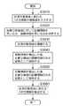
ここで、図3を用いて、図1に示す3次元計測装置1により計測対象物体の位置及び姿勢を計測する際の処理の流れの一例について説明する。 Here, an example of a processing flow when measuring the position and orientation of the measurement target object by the three-
(S1010)
3次元計測装置1は、概略値入力部120において、計測対象物体に係わる3次元情報の概略情報(すなわち、3次元計測装置1に対する物体の位置及び姿勢の概略値)を入力する。本実施形態においては、上述した通り、物体の位置及び姿勢の概略値として、3次元計測装置1が当該物体から過去(例えば、直前)に計測した計測値を用いる。(S1010)
In the approximate
(S1020)
3次元計測装置1は、照明領域決定部130において、照明領域(距離計測用の領域)を決定する。上述した通り、照明領域は、計測対象物体の3次元形状モデルと、計測対象物体の位置及び姿勢の概略値とに基づいて決められる。また、上述した通り、距離計測用の照明は、濃淡変化が小さく、画像特徴(エッジ)が検出され難い領域に対して行なわれる。(S1020)
In the three-
ここで、照明領域決定部130による距離計測用の領域の決定処理について説明する。距離計測用の領域の決定に際しては、計測対象物体の面を画像上に描画(投影)し、その背景部分と物体部分とを切り分ける。この描画は、例えば、撮像部150の内部パラメータと、計測対象物体の位置及び姿勢の概略値とに基づいて行なわれる。 Here, the determination process of the area | region for distance measurement by the illumination area |
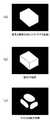
ここで、照明領域決定部130は、まず、撮像部150が撮像する画像と同一サイズのマスク画像を用意し、そのマスク画像の全ての画素の値を0で初期化する。次に、照明領域決定部130は、グラフィックスハードウェアを用いて、計測対象物体の位置及び姿勢の概略値に基づいて当該物体の3次元形状モデルの画像(3次元形状モデル画像)を描画する。このとき、3次元形状モデル画像内の背景は、黒く描画し、また、物体の面は、白く描画する(図4(a))。そして、その描画した画像内における白い画素については、マスク画像の値を1に書き換える。また、照明領域決定部130は、グラフィックスハードウェアを用いて、3次元形状モデル画像内の物体の線分を黒く描画する(図4(b))。ここで、照明領域決定部130は、3次元形状モデル画像内において黒く、また、その対応するマスク画像における値が1である画素について、マスク画像の値を0に書き換える。 Here, the illumination
最後に、照明領域決定部130は、マスク画像において値が1となる所定の画素の値を0に書き換える。具体的には、マスク画像において、画素の値が0となる画素の近傍(所定範囲内)にあり、その値が1となる画素の値を1から0に書き換える(図4(c))。 Finally, the illumination
ここで、照明領域決定部130は、上述した処理により得られたマスク画像内で1の値を持つ画素を照明領域(すなわち、距離計測用の領域)に決定する。なお、撮像部150と照明部140との間の相対的な位置及び姿勢には、オフセットがある。そのため、両者の幾何学的関係を用いて、撮像部150により撮像された画像内における各画素の位置を、照明部140による照明パターンにおける各画素の位置に変換する必要がある。具体的には、照明領域決定部130は、グラフィックスハードウェアを用いて、計測対象物体をZバッファ上に描画する。そして、マスク画像の値が1である画素の(撮像部150を基準とした)3次元座標値を、当該画素の座標とZバッファとの値を用いて算出する。その後、照明領域決定部130は、撮像部150と照明部140との間の相対的な位置及び姿勢を示す値と、照明部140の内部パラメータとに基づいて、当該求めた3次元座標値を照明パターンの座標(距離計測用の領域を示す座標)に変換する。 Here, the illumination
なお、ここでは、グラフィックスハードウェアを用いて3次元形状モデルの投影像(線分及び面)を描画する場合について説明したが、これに限られず、CPU等により描画を行なっても良い。 Although a case has been described here in which the projection image (line segment and surface) of the three-dimensional shape model is drawn using graphics hardware, the present invention is not limited to this, and the drawing may be performed by a CPU or the like.
(S1030)
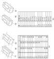
3次元計測装置1は、照明部140において、S1020のマスク処理において決定された距離計測用の領域に対して所定の照明パターン(構造化光)を局所的に照射する。上述した通り、この照明は、液晶プロジェクタ等の照明装置を制御することにより行なわれる。この処理では、図5に示すように、距離計測用の領域(画素単位)に構造化光(この場合、マルチスリット光)が照射される。すなわち、画面全体ではなく、S1020のマスク処理により決定された領域(距離計測用の領域)のみに照射が行なわれる。(S1030)
In the
なお、本実施形態においては、構造化光としてマルチスリット光を用いる場合を例に挙げて説明するが、構造化光は、これに限られず、複数回の撮像を必要としないのであれば、他の手段を用いても良い。距離計測用の照明が照射されない領域(すなわち、画像特徴検出用の領域)は、環境光により十分な明るさが得られればよく、特別な光を照射する必要はない。環境光により十分な明るさが得られないのであれば、例えば、均一な白色光が照射されるように照明パターンを変更すれば良い。 In this embodiment, the case where multi-slit light is used as the structured light will be described as an example. However, the structured light is not limited to this, and other structures may be used as long as they do not require multiple imaging. The means may be used. A region that is not irradiated with illumination for distance measurement (that is, a region for image feature detection) only needs to have sufficient brightness by ambient light, and does not need to be irradiated with special light. If sufficient brightness cannot be obtained by the ambient light, for example, the illumination pattern may be changed so that uniform white light is emitted.
(S1040)
3次元計測装置1は、撮像部150において、計測対象物体の画像を撮像する。上述した通り、この撮像では、画像特徴検出用の画像と距離計測用の画像とが1枚の画像として同時に撮像される。なお、この撮像は、距離計測を行なう領域に対して局所的に照明が行なわれた状態で行なわれる。(S1040)
The three-
(S1050)
3次元計測装置1は、画像特徴検出部160において、撮像部150により撮像された画像から画像特徴の検出を行なう。本実施形態においては、上述した通り、画像特徴としてエッジを検出する。例えば、非特許文献1に開示された技術を用いてエッジの検出を行なう。ここで、図6を用いて、本実施形態に係わるエッジ検出方法の概要の一例について説明する。エッジ検出では、まず、撮像された計測対象物体の画像に対して投影する投影像(線分)を求める。投影像は、S1010で入力された計測対象物体の位置及び姿勢の概略値に基づいて求められる。次に、投影された各線分上において、等間隔に制御点を設定する。そして、投影された線分の法線方向に平行で且つ制御点を通過する線分(以下、探索ライン)上からエッジを1次元探索する(図6(a))。エッジは、画素値の濃度勾配の極値となる(図6(b))。場合によっては、探索ライン上から複数のエッジが検出されることがある。この場合、本実施形態においては、「L. Vacchetti, V. Lepetit, and P. Fua, "Combining edge and texture information for real-time accurate 3D camera tracking," Proc. ISMAR04, pp.48-57, 2004」に開示された技術を用いる。すなわち、この文献に開示された方法を用いて複数検出されたエッジを仮説として保持する。このようにして各制御点に対応したエッジを探索し、後述するS1070における処理において、3次元の線分をエッジにあてはめる。なお、各制御点の画像を1画素単位で量子化した座標が、距離計測用の領域(画素)に相当する場合、該当する画素のエッジ検出は行なわない。(S1050)
In the three-
(S1060)
3次元計測装置1は、距離算出部170において、撮像部150により撮像された画像に基づいて距離を算出(計測)する。具体的には、距離計測用の領域(画素)に基づいて距離を算出する。距離は、上述した通り、三角測量により算出される。距離の算出に際しては、照明部140により照射された領域(画像における画素の位置)と、撮像部150により撮像された画像上における当該領域に対応する位置とが用いられる。また、これ以外にも、照明部140及び撮像部150の内部パラメータや、撮像部150と照明部140との間の相対的な位置及び姿勢を示す値も用いられる。(S1060)
In the three-
距離算出部170では、距離計測を行なった後、撮像された画像内における計測対象物体を、撮像部150の座標系で3次元座標値を持つ点群データに変換する。3次元座標値は、撮像された画像内の計測対象物体における各点の位置に対応する視線ベクトルに距離情報を乗算することにより算出される。 The
(S1070)
3次元計測装置1は、位置姿勢算出部180において、計測対象物体に係わる3次元情報(3次元計測装置1に対する計測対象物体の位置及び姿勢)を算出(計測)する。(S1070)
In the three-
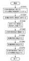
次に、図7を用いて、図3のS1070における位置姿勢算出処理について詳述する。この処理では、ガウス−ニュートン(Gauss-Newton)法により反復演算し、計測対象物体の位置及び姿勢(以下、sで表す)の概略値を補正する。これにより、計測対象物体の位置及び姿勢を算出する。なお、位置姿勢算出処理は、ガウス−ニュートン法に限られない。例えば、より計算がロバストであるLevenberg−Marquardt法を用いてもよいし、よりシンプルな方法である最急降下法を用いても良い。また、共役勾配法やICCG法など、他の非線形最適化計算手法を用いても良い。 Next, the position and orientation calculation process in S1070 of FIG. 3 will be described in detail with reference to FIG. In this process, iterative calculation is performed by the Gauss-Newton method, and the approximate value of the position and orientation (hereinafter represented by s) of the measurement target object is corrected. Thereby, the position and orientation of the measurement target object are calculated. The position / orientation calculation process is not limited to the Gauss-Newton method. For example, the Levenberg-Marquardt method whose calculation is more robust may be used, or the steepest descent method which is a simpler method may be used. Further, other nonlinear optimization calculation methods such as a conjugate gradient method and an ICCG method may be used.
ここでは、検出されたエッジと投影される3次元形状モデルの線分との間の画像上(2次元平面上)での距離、点群データを構成する点と投影される3次元形状モデルの面との間の撮像部150の座標系(三次元空間中)での距離、の総和(2乗和)を最小化する。これにより、計測対象物体に対する位置及び姿勢を最適化する。より具体的には、1次のテイラー展開により、2次元画像上での点及び直線の符号付距離と、3次元空間中での点及び平面の符号付距離とをそれぞれ、物体の位置及び姿勢の微小変化を示す1次関数として表現する。そして、符号付距離が0になるような位置及び姿勢の微小変化に係わる線形の連立方程式を立式して解く。これにより、物体の位置及び姿勢の微小変化を求め、この値を補正する処理を繰り返す。 Here, the distance on the image (on the two-dimensional plane) between the detected edge and the line segment of the projected three-dimensional shape model, the points constituting the point cloud data, and the projected three-dimensional shape model The total sum (square sum) of the distance in the coordinate system (in the three-dimensional space) of the
(S1210)
3次元計測装置1は、位置姿勢算出部180において、まず、初期化処理を行なう。この初期化処理では、例えば、図3のS1010で得られた計測対象物体の位置及び姿勢の概略値を入力する。(S1210)
The three-
(S1220)
3次元計測装置1は、位置姿勢算出部180において、エッジ及び点群データと、3次元形状モデルとを対応付けする。この処理では、まず、S1210で得られた計測対象物体の位置及び姿勢の概略値に基づいて3次元形状モデルの各線分を画像へ投影し、投影された3次元形状モデルの各面を撮像部150の座標系へ座標変換する。そして、エッジ及び点群データと、3次元形状モデルとを対応付けする。エッジが、各制御点に対応して複数検出された場合には、複数検出されたエッジのうち、投影された線分に対して画像上で最も近いエッジを制御点に対応付ける。この対応付けは、S1210で得られた計測対象物体の位置及び姿勢の概略値に基づいて行なう。また、点群データについては、撮像部150の座標系における各点の3次元座標に基づいて3次元形状モデル中の最も近接する面を探索し対応付ける。(S1220)
In the three-
(S1230)
3次元計測装置1は、位置姿勢算出部180において、線形連立方程式を解くための係数行列と誤差ベクトルとを算出する。ここで、係数行列の各要素は、S1210で得られた概略値の微小変化に対する一次の偏微分係数である。エッジについては、画像座標の偏微分係数を算出し、点群データについては、3次元座標の偏微分係数を算出する。また、エッジの誤差ベクトルは、投影された線分と検出されたエッジとの間の2次元平面上(画像)での距離であり、点群データの誤差ベクトルは、点群データを構成する点と3次元形状モデルの面との3次元空間中での距離である。(S1230)
In the three-
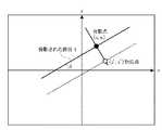
ここで、図8は、線分の投影像と検出されたエッジとの関係の一例を示す図である。この場合、画像の水平方向をu軸とし、垂直方向をv軸としている。ある制御点(投影された各線分を画像上で等間隔に分割した点)の画像上での位置を(u0,v0)と表し、当該制御点が属する線分Lの画像上での傾きを(u軸に対する傾き)θと表す。傾きθは、線分Lの両端の3次元座標をsに基づいて画像上に投影し、画像上での両端の座標を結んだ直線の傾きとして算出する。線分Lの画像上での法線ベクトルは(sinθ,−cosθ)となる。また、制御点と対応する点の座標を(u’,v’)とする。ここで、点(u’,v’)を通り、傾きがθである直線上の点(u,v)は、
制御点の画像上での位置は、計測対象物体の位置及び姿勢により変化する。計測対象物体の位置及び姿勢は、6自由度である。すなわち、sは6次元ベクトルであり、計測対象物体の位置を表す3つの要素と、姿勢を表す3つの要素とからなる。姿勢を表す3つの要素は、例えば、オイラー角による表現や、方向が回転軸を表し大きさが回転角を表す3次元ベクトルなどによって表現される。制御点の座標(u,v)は、(u0,v0)の近傍で1次のテイラー展開によって「数2」のように近似できる。但し、Δsi(i=1,2,・・・,6)は、sの各成分の微小変化を表す。
正しいsによって得られる画像上での制御点の位置は、「数1」が表す直線上にあると仮定できる。「数2」によって近似されるu、vを「数1」に代入することにより、「数3」が得られる。
撮像部150の座標系における3次元座標は、計測対象物体の位置及び姿勢sによって計測対象物体の座標系における3次元座標(x,y,z)に変換することができる。S1210で得た概略値により、ある点が計測対象物体の座標系の点(x0,y0,z0)に変換されるとする。(x,y,z)は、計測対象物体の位置及び姿勢により変化するため、(x0,y0,z0)の近傍で1次のテイラー展開によって「数4」のように近似できる。
S1220において、点群データ中のある点に対応付けられた3次元形状モデルの面の計測対象物体の座標系における方程式を「ax+by+cz=e(a2+b2+c2=1、a,b,c,eは定数)」とする。正しいsによって変換された(x,y,z)は、平面の方程式「ax+by+cz=e(a2+b2+c2=1)」を満たすと仮定する。「数4」を平面の方程式に代入すると「数5」が得られる。
「数3」は、S1220で対応付けが行なわれた全てのエッジについて成り立つ。また、「数5」は、S1220で対応付けが行なわれた全ての点群データについて成り立つ。そのため、「数6」のようなΔsiに係わる線形連立方程式が成り立つ。
ここで、「数6」を「数7」のように表す。
「数6」の線形連立方程式の係数行列Jを算出するための偏微分係数の算出は、例えば、非特許文献1に開示された技術を用いて行なう。 The partial differential coefficient for calculating the coefficient matrix J of the linear simultaneous equations of “Equation 6” is calculated using, for example, the technique disclosed in
(S1240)
「数7」をもとに、行列Jの一般化逆行列(JT・J)−1・JTを用いて補正値Δsを求める。ここで、エッジや点群データには、誤検出などによる外れ値が多いため、次に述べるようなロバスト推定手法を用いる。一般に、外れ値であるエッジ(又は点群データ)では、誤差d−r(e−q)が大きくなる。そのため、「数6」、「数7」の連立方程式に対する寄与度が大きくなり、その結果得られるΔsの精度が低下してしまう。そこで、誤差d−r(e−q)が大きいデータに対しては小さな重みを与え、誤差d−r(e−q)が小さいデータに対しては大きな重みを与える。重みは、例えば、「数8」に示すようなTukeyの関数により与える。
Based on “Expression 7”, a correction value Δs is obtained using a generalized inverse matrix (JT · J)−1 · JT of the matrix J. Here, since there are many outliers due to erroneous detection or the like in the edge and point cloud data, the following robust estimation method is used. Generally, an error dr−e (e−q) becomes large at an edge (or point group data) that is an outlier. For this reason, the degree of contribution to the simultaneous equations of “Equation 6” and “Equation 7” increases, and the accuracy of Δs obtained as a result decreases. Therefore, a small weight is given to data having a large error dr (eq), and a large weight is given to data having a small error dr (eq). The weight is given by, for example, a Tukey function as shown in “Equation 8”.
各データ(エッジ又は点群データ)に対応する重みをwiとする。ここで、「数9」のように重み行列Wを定義する。
重み行列Wは、対角成分以外は全て0の正方行列であり、対角成分には重みwiが入る。この重み行列Wを用いて、「数7」を「数10」のように変形する。
「数11」のように「数10」を解くことにより補正値Δsを求める。
3次元計測装置1は、S1240で算出された補正値Δsにより、S1210で得た概略値を補正する。これにより、計測対象物体の位置及び姿勢を算出する。The correction value Δs is obtained by solving “
The three-
(S1260)
3次元計測装置1は、収束しているか否かの判定を行なう。収束していれば、この処理は終了し、そうでなければ、再度、S1220の処理に戻る。なお、収束しているか否かは、補正値Δsがほぼ0である場合や、誤差ベクトルの二乗和の補正前と補正後の差がほぼ0である場合に収束したと判定する。(S1260)
The three-
以上説明したように実施形態1によれば、計測対象物体の位置及び姿勢の概略値と、計測対象物体の3次元形状モデルとに基づいて局所的に照明を照射し、その状態で計測対象物体を撮像する。そして、その撮像された画像に対して画像特徴の検出と距離情報の検出とを実施し、その結果に基づいて計測対象物体に係わる3次元情報を算出する。すなわち、画像特徴検出用の画像(2次元画像)と距離計測用の画像(3次元画像)とを相補的に利用して計測対象物体の位置及び姿勢を計測する。 As described above, according to the first embodiment, illumination is locally irradiated based on the approximate value of the position and orientation of the measurement target object and the three-dimensional shape model of the measurement target object, and the measurement target object is in that state. Image. Then, image feature detection and distance information detection are performed on the captured image, and three-dimensional information related to the measurement target object is calculated based on the result. That is, the position and orientation of the measurement target object are measured by complementarily using the image feature detection image (two-dimensional image) and the distance measurement image (three-dimensional image).
これにより、計測対象物体の表面属性や構造に左右されず、当該物体に係わる3次元情報の計測を高精度に行なうことができる。また、3次元計測装置の構成も複雑化しない。 Thus, measurement of three-dimensional information related to the object can be performed with high accuracy regardless of the surface attribute and structure of the measurement target object. Further, the configuration of the three-dimensional measuring apparatus is not complicated.
更に、画像特徴検出用の画像と距離計測用の画像とを1枚の画像として撮像するため、3次元計測装置と計測対象物体との間の位置及び姿勢の関係が高速に変化している場合であっても、当該物体に係わる3次元情報の計測を高精度に行なえる。また、計測処理の高速化も図れる。 Furthermore, when the image feature detection image and the distance measurement image are captured as a single image, the position and orientation relationship between the three-dimensional measurement device and the measurement target object changes at high speed. Even so, it is possible to measure the three-dimensional information related to the object with high accuracy. In addition, the measurement process can be speeded up.
なお、上述した実施形態1では、画像特徴検出用の画像と距離計測用の画像とを1枚の画像として同時に取得する場合について説明したが、画像特徴検出用の画像と距離計測用の画像とを別々に撮像しても良い。例えば、3次元計測装置と計測対象物体とが共に静止しているのであれば、それぞれが異なるタイミングで撮像された画像を用いても、上述した処理が行なえる。 In the first embodiment described above, the case where the image feature detection image and the distance measurement image are simultaneously acquired as one image has been described. However, the image feature detection image, the distance measurement image, May be imaged separately. For example, if the three-dimensional measurement apparatus and the measurement target object are both stationary, the above-described processing can be performed using images captured at different timings.
(実施形態2)
次に、実施形態2について説明する。実施形態2においては、複数の撮像装置を用いて、計測対象物体の各部から距離情報を取得し、その距離情報に基づいて計測対象物体の位置及び姿勢の計測を行なう場合について説明する。(Embodiment 2)
Next,
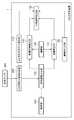
図9は、実施形態2に係わる3次元計測装置1の構成の一例を示す図である。なお、実施形態1における図1と同一の符号が付してあるものは同様の機能を有する。ここでは、実施形態1との相違点について重点的に説明する。 FIG. 9 is a diagram illustrating an example of the configuration of the three-
3次元計測装置1は、3次元形状モデル保持部110と、概略値入力部120と、照明領域決定部130と、照明部140と、撮像部150と、距離算出部170と、位置姿勢算出部180とを具備して構成される。すなわち、実施形態1の構成から画像特徴検出部160が除かれている。 The three-
ここで、撮像部150は、複数の撮像装置190から構成される。各撮像装置190の内部パラメータ(例えば、焦点距離、主点位置)や、各撮像装置190同士の幾何学的関係は、予め校正しておく。照明部140の内部パラメータも予め校正しておく。各撮像装置同士の幾何学的関係は、既知のパターン(例えば、格子模様の描かれた平面パターン)を撮像し、その撮像された画像の対応点をもとにEssential行列を算出し、そのEssential行列を位置及び姿勢に分解することにより校正すれば良い。 Here, the
距離算出部170は、撮像部150により撮像された画像に基づいて計測対象物体における点の距離(距離情報)を算出(計測)する。距離の算出は、画像上の大多数の画素について行なっても良いし、例えば、Harris検出器といった特徴点検出器により検出される特徴点のみについて行なっても良い。すなわち、複数の撮像装置の間で対応付けることができるのであれば、いかなる点を距離の算出対象としても良い。 The
位置姿勢算出部180は、画像特徴の検出結果を用いずに、計測対象物体の位置及び姿勢を算出(計測)する。すなわち、実施形態2においては、距離算出部170により算出された距離情報に基づいて計測対象物体の位置及び姿勢を算出する。具体的には、距離算出部170により算出された距離情報に3次元形状モデルをあてはめることにより、計測対象物体の位置及び姿勢を算出する。 The position /
ここで、図10を用いて、実施形態2に係わる3次元計測装置1により計測対象物体の位置及び姿勢を計測する際の処理の流れの一例について説明する。 Here, an example of the flow of processing when measuring the position and orientation of the measurement target object by the three-
(S2010)
3次元計測装置1は、概略値入力部120において、計測対象物体に係わる3次元情報の概略値(すなわち、3次元計測装置1に対する物体の位置及び姿勢の概略値)を入力する。このS2010における処理は、実施形態1を説明した図3のS1010の処理と同様となる。(S2010)
In the approximate
(S2020)
3次元計測装置1は、照明領域決定部130において、照明領域(すなわち、距離計測用の領域)を決定する。このS2020における処理は、実施形態1を説明した図3のS1020の処理と同様となる。(S2020)
In the three-
(S2030)
3次元計測装置1は、照明部140において、S2020で決定された距離計測用の領域に対して所定の照明パターン(構造化光)を照射する。距離計測用の照明は、例えば、撮像部150により撮像される画像内において、濃淡変化が小さく、画像特徴が検出され難い領域に対して行なわれる。このS2030における処理は、実施形態1を説明した図3のS1030の処理と同様となる。なお、実施形態1と同様に、距離計測用の照明が照射されない領域(すなわち、画像特徴検出用の領域)は、環境光により十分な明るさが得られればよく、特別な光を照射する必要はない。環境光により十分な明るさが得られないのであれば、例えば、均一な白色光が照射されるように照明パターンを変更すれば良い。(S2030)
In the
(S2040)
3次元計測装置1は、撮像部150を構成する複数の撮像装置190により計測対象物体の画像を撮像する。なお、この撮像は、距離計測を行なう領域に対して局所的に照明が行なわれた状態で行なわれる。(S2040)
The three-
(S2050)
3次元計測装置1は、距離算出部170において、撮像部150により撮像された画像に基づいて距離(距離情報)を算出(計測)する。実施形態2においては、撮像された画像から特徴点の検出は行なわず、基準とする撮像装置190が撮像する画像の全画素について距離算出を行なう。距離の算出に際しては、各撮像装置190で撮像された画像間で各画素の対応付けが必要となる。距離計測用の領域においては、構造化光(例えば、マルチスリット光)の投影像を時系列に追跡し、画像間における各画素の対応付けを行なう。照明が照射されない領域については、例えば、エピポーラ拘束により決定されるエピポーラ線上の点に対して画素値のブロックマッチングを実施し、画像間における各画素を対応付ければ良い。なお、画像間における各画素の対応付けは、これに限られない。例えば、「E. Tola, V. Lepetit, and P. Fua, “A fast local descriptor for dense matching," Proc. CVPR'08, 2008」に開示されるような局所的な記述子を用いて対応付けを行なっても良い。また、構造化光として、マルチスリット光ではなく、例えば、ランダムドットパターンを用いるようにしても良い。この場合、時系列に追跡せずに、画像間における各画素の対応付けを行なえる。(S2050)
In the three-
(S2060)
3次元計測装置1は、位置姿勢算出部180において、計測対象物体に係わる3次元情報(3次元計測装置1に対する計測対象物体の位置及び姿勢)を算出(計測)する。ここでは、S2050で算出された距離情報を3次元座標値を持つ点群データに変換し、点群データに3次元形状モデルをあてはめるべく、計測対象物体の位置及び姿勢を算出する。この処理では、まず、点群データの各点に対して、3次元形状モデル中の最も近接する面を選択し、それぞれを対応付ける。そして、各点と対応する面との距離の総和が最小化するように、計測対象物体の位置及び姿勢の概略値に対して補正を繰り返し行なう。これにより、計測対象物体の位置及び姿勢を算出する。なお、S2060における位置姿勢算出処理は、基本的には、実施形態1を説明した図3のS1070の処理と同様となる。相違点としては、画像特徴に関する処理を行なわない点である。そのため、ここではその詳細な説明については省略する。(S2060)
In the three-
以上説明したように実施形態2によれば、画像特徴の検出処理を行なわずに、複数の撮像装置から得られる距離情報に基づいて計測対象物体に係わる3次元情報の計測を行なう。具体的には、計測対象物体中の濃淡変化の乏しい領域を照明し、計測対象物体の各部から満遍なく距離情報を取得する。これにより、実施形態1と同様に、計測対象物体の表面属性や構造に左右されず、当該物体に係わる3次元情報の計測を高精度に行なうことができる。また、3次元計測装置の構成も複雑化しない。 As described above, according to the second embodiment, three-dimensional information related to a measurement target object is measured based on distance information obtained from a plurality of imaging devices without performing image feature detection processing. Specifically, a region with a small change in shading in the measurement target object is illuminated, and distance information is obtained uniformly from each part of the measurement target object. Thereby, similarly to
(実施形態3)
次に、実施形態3について説明する。上述した実施形態1及び2においては、距離計測用の領域に対して局所的に照明を行なう場合(照明制御)について説明した。これに対して、実施形態3においては、照明制御を行なわずに、上述した実施形態1及び2と同等の処理を行なう場合について説明する。(Embodiment 3)
Next, Embodiment 3 will be described. In the first and second embodiments described above, the case where illumination is locally performed on the distance measurement region (illumination control) has been described. On the other hand, in the third embodiment, a case will be described in which processing equivalent to that in the first and second embodiments described above is performed without performing illumination control.
図11は、実施形態3に係わる3次元計測装置1の構成の一例を示している。なお、実施形態1における図1と同一の符号が付してあるものは同様の機能を有する。ここでは、実施形態1との相違点について重点的に説明する。 FIG. 11 shows an example of the configuration of the three-
3次元計測装置1は、3次元形状モデル保持部110と、概略値入力部120と、領域決定部230と、照明部140と、撮像部150と、画像特徴検出部160と、距離算出部170と、位置姿勢算出部180とを具備して構成される。すなわち、実施形態1の構成から照明領域決定部130が除かれ、領域決定部230が新たに設けられている。 The three-
領域決定部230は、距離計測に用いる領域(本実施形態においては、領域の単位は画素を指す)を決定する。この領域は、3次元形状モデル保持部110に保持された計測対象物体の3次元形状モデルと、概略値入力部120により入力された計測対象物体の位置及び姿勢の概略値とに基づき決められる。すなわち、撮像部150が撮像する画像内の各領域を判定し、距離計測用の領域を決定する。なお、距離計測を行なうと決められた領域以外から画像特徴の検出が行なわれることになる。 The
画像特徴検出部160は、撮像部150により撮像された画像から計測対象物体を示す画像特徴を検出する。なお、実施形態3においては、画像特徴検出部160は、対象となる領域を特に限定せずに画像特徴の検出を行なう。画像特徴検出部160により検出された画像特徴は、領域決定部230の決定結果に基づいて取捨選択される。 The image
距離算出部170は、計測対象物体における一つ以上の点の距離を算出する。ここでは、構造化光(マルチスリット光)を物体に照射して撮像された画像内におけるスリットの投影像と、照明部140及び撮像部150の幾何学的関係とを用いて、スリット光が照射された領域の距離を三角測量により算出する。距離の算出は、対象となる領域を特に限定せずに行なう。距離算出部170により算出された距離情報は、領域決定部230の決定結果に基づいて取捨選択される。 The
位置姿勢算出部180は、計測対象物体に係わる3次元情報(すなわち、計測対象物体の位置及び姿勢)を算出する。この3次元情報の算出は、例えば、画像特徴検出部160により検出された画像特徴と、距離算出部170により算出された距離情報とに基づいて行なわれる。 The position /
ここで、図12を用いて、実施形態3に係わる3次元計測装置1により計測対象物体の位置及び姿勢を計測する際の処理の流れの一例について説明する。 Here, an example of the flow of processing when measuring the position and orientation of the measurement target object by the three-
(S3010)
3次元計測装置1は、概略値入力部120において、計測対象物体に係わる3次元情報の概略値(すなわち、3次元計測装置1に対する物体の位置及び姿勢の概略値)を入力する。本実施形態においては、物体の位置及び姿勢の概略値として、3次元計測装置1が当該物体から過去(例えば、直前)に計測した計測値を用いる。(S3010)
In the approximate
(S3020)
3次元計測装置1は、領域決定部230において、撮像部150が撮像する画像の各領域に対して距離情報に用いるか、画像特徴に用いるかを決定する。なお、この領域は、3次元形状モデル保持部110に保持された計測対象物体の3次元形状モデルと、概略値入力部120により入力された計測対象物体の位置及び姿勢の概略値とに基づいて決められる。領域の決定方法は、実施形態1を説明した図3のS1020と同様であるのでその詳細な説明については省略する。(S3020)
In the three-
(S3030)
3次元計測装置1は、撮像部150において、計測対象物体の画像を撮像する。(S3030)
The three-
(S3040)
3次元計測装置1は、画像特徴検出部160において、撮像部150により撮像された画像に基づいて画像特徴の検出を行なう。ここでは、実施形態1と同様に、画像特徴としてエッジを検出する。実施形態1においては、距離計測を行なうと決定された領域(画素)に対してはエッジの検出を行なわなかったが、実施形態3においては、画像全体からエッジの検出を行なう。その点を除いては、実施形態1を説明した図3のS1050と同様であるのでその詳細な説明については省略する。なお、上述した通り、画像全体からエッジ検出を行なった後、領域決定部230の決定結果に基づいてその検出されたエッジの取捨選択が行なわれる。エッジの取捨選択では、各制御点の画像を1画素単位で量子化した座標が、S3020で距離計測を行なうと決定された領域(画素)に相当する場合、該当する画素のエッジの検出結果を削除する。(S3040)
In the three-
(S3050)
3次元計測装置1は、距離算出部170において、計測対象物体における点の距離の算出(計測)を行なう。上述したように、マルチスリット光を物体に照射した画像を撮像し、その撮像された画像におけるスリットの投影像と、照明部140及び撮像部150の幾何学的関係とを用いてスリット光が照射された領域の距離を三角測量により算出する。距離の算出は、対象となる領域を特に限定せずに行なう。上述した通り、画像全体から距離の算出が行なわれた後、領域決定部230の決定結果に基づいてその検出された距離情報の取捨選択が行なわれる。距離情報の取捨選択では、まず、計測された距離を距離算出部170の座標系における3次元座標に変換した後、更に、その座標値を撮像部150の座標系に変換し、その結果を画像へ投影する。そして、投影された画像座標を1画素単位で量子化した座標が、S3020で距離情報を用いると決定された領域(画素)の座標以外の領域であれば、該当する距離計測の結果を削除する。(S3050)
In the three-
(S3060)
3次元計測装置1は、位置姿勢算出部180において、計測対象物体に係わる3次元情報(3次元計測装置1に対する計測対象物体の位置及び姿勢)を算出(計測)する。この算出は、S3040で検出された画像特徴と、S3050で算出された距離情報とに基づいて行なわれる。なお、計測対象物体の位置姿勢算出処理は、実施形態1を説明した図3のS1070と同様であるのでその詳細な説明については省略する。(S3060)
In the three-
以上説明したように実施形態3によれば、照明制御を行なわずに、上述した実施形態1及び2と同様の結果を得ることができる。これにより、実施形態1及び2同様に、計測対象物体の表面属性や構造に左右されず、当該物体に係わる3次元情報の計測を高精度に行なうことができる。また、3次元計測装置の構成も複雑化しない。 As described above, according to the third embodiment, the same result as in the first and second embodiments can be obtained without performing illumination control. Thereby, similarly to
なお、上述した実施形態3では、撮像された画像全体に対して画像特徴の検出や距離情報の算出を行なった後、領域決定部230による決定結果に基づいてエッジの検出結果や距離計測の結果を取捨選択していたが、これに限られない。例えば、領域決定部230の決定結果に基づいて必要となる領域のみから画像特徴を検出したり、距離情報を算出したりするようにしても良い。この場合、画像全体に対して画像特徴の検出や距離情報の算出を行なう必要がなくなるので、処理の高速化が期待できる。 In Embodiment 3 described above, after detecting image features and calculating distance information for the entire captured image, the edge detection result and the distance measurement result based on the determination result by the
(実施形態4)
次に、実施形態4について説明する。上述した実施形態1〜3においては、計測対象物体の三次元形状モデルを用いて距離計測用の領域を決定する場合について説明した。これに対して、実施形態4においては、計測対象物体の三次元形状モデルを用いずに、距離計測用の領域を決定する場合について説明する。(Embodiment 4)
Next, Embodiment 4 will be described. In the first to third embodiments described above, the case where the distance measurement region is determined using the three-dimensional shape model of the measurement target object has been described. On the other hand, in the fourth embodiment, a case will be described in which a distance measurement region is determined without using a three-dimensional shape model of a measurement target object.
図13は、実施形態4に係わる3次元計測装置1の構成の一例を示している。なお、実施形態1における図1と同一の符号が付してあるものは同様の機能を有する。ここでは、実施形態1との相違点について重点的に説明する。 FIG. 13 shows an example of the configuration of the three-
3次元計測装置1は、実施形態1の構成に加えて、3次元形状情報取得部200が新たに設けられる。3次元形状情報取得部200は、外部に設けられた距離センサ300と接続されている。 The three-
3次元形状情報取得部200は、計測対象物体の3次元形状を示す情報を取得する。本実施形態においては、計測対象物体の3次元形状を示す情報として、距離センサ300から距離画像(計測対象物体及びその周辺の3次元形状)を取得する。ここで、距離センサ300は、例えば、シーン中に固定されている。距離センサ300は、距離画像を計測できれば良く、いかなる方式を採用しても良い。例えば、距離計測時に照明を行なうアクティブ式であっても良いし、複数の撮像装置を利用するパッシブ式であっても良い。また、例えば、Time−of−Flight方式などの三角測量を利用しない方式を採用していても良い。 The three-dimensional shape
なお、距離センサ300と撮像部150との間の相対的な位置及び姿勢を示す値は、既知であるものとする。例えば、撮像部150がロボットアームに搭載されている場合には、ロボット座標系における距離センサ300の位置及び姿勢を予め求めておく。3次元計測装置1においては、計測に際してロボットから出力される動きパラメータを用いて、ロボット座標系における撮像部150の位置及び姿勢を算出し、距離センサ300と撮像部150との間の相対的な位置及び姿勢を示す値に変換する。 In addition, the value which shows the relative position and attitude | position between the
照明領域決定部130は、距離センサ300から得られる距離画像に基づいて距離計測用の領域を決定する。より具体的には、距離画像における各画素の距離情報に基づいて距離画像を領域分割し、当該分割された領域の中から距離計測用の領域を決定する。 The illumination
次に、図14を用いて、実施形態4に係わる3次元計測装置1により計測対象物体の位置及び姿勢を計測する際の処理の流れの一例について説明する。なお、実施形態4に係わる3次元計測装置1の全体的な動作は、実施形態1を説明した図3と同様となるため、ここでは相違する点(S1020の領域決定処理)について説明する。 Next, an example of the flow of processing when measuring the position and orientation of the measurement target object by the three-
(S4010)
領域決定処理では、まず、3次元計測装置1は、3次元形状情報取得部200において、距離センサ300から距離画像を取得する。なお、距離センサ300における距離画像の取得は、3次元計測装置1からの指示に基づいて行なわれても良いし、距離センサ300側で独立して行なっておき、最新の距離画像を3次元形状情報取得部200側に渡すようにしても良い。(S4010)
In the region determination process, first, the three-
(S4020)
次に、3次元計測装置1は、照明領域決定部130において、距離画像を領域分割する。領域分割では、隣り合う画素を比較し、距離が大きく変化しない画素群を一つの領域としてまとめる。これにより、距離画像を複数の領域に分割する。領域分割は、例えば、「X. Jiang and H. Bunke, "Range Image Segmentation: Adaptive Grouping of Edges into Regions," Proc. ACCV '98, pp.299-306, 1998.」に開示された技術を用いて行なえば良い。なお、距離計測の対象となる領域は、一定以上(所定値以上)の面積を持つ領域が対象となる。(S4020)
Next, the three-
(S4030)
次に、3次元計測装置1は、照明領域決定部130において、S4020で距離計測の対象となった領域を、距離センサ300と撮像部150との間の相対的な位置及び姿勢を示す値を用いて撮像部150の画像と同サイズのマスク画像に投影する。ここでは、実施形態1で説明した通り、マスク画像の各画素は0で初期化しておき、領域が投影された画素の値を1に変更する。全ての対象領域の投影が終われば、マスク画像上で値が1となっている画素の座標を、当該座標及び距離情報に基づいて撮像部150を基準とした3次元座標に変換する。具体的には、距離センサ300と撮像部150との間の相対的な位置及び姿勢を示す値を用いて、距離センサ300により取得された距離画像を撮像部150の座標系における距離画像に変換する。そして、当該変換後の距離画像内の各画素における座標及び距離情報に基づいて3次元座標を生成(変換)する。その後、撮像部150と照明部140との間の相対的な位置及び姿勢を示す値と、照明部140の内部パラメータとに基づいて、当該求めた3次元座標を照明パターンの座標(距離計測用の領域を示す座標)に変換する。(S4030)
Next, in the illumination
3次元計測装置1は、照明部140において、上述した処理で決められた距離計測用の領域に対して所定の照明パターン(構造化光)を照射する。なお、以降の処理については、実施形態1と同様の流れとなるため、その説明については省略する。 In the
以上説明したように実施形態4によれば、計測対象物体の3次元形状モデルを用いずに、外部のセンサ(他の視点)から得られた距離画像を用いて距離計測用の領域を決定する。この場合にも、上述した実施形態1〜3と同様の結果を得ることができる。 As described above, according to the fourth embodiment, a distance measurement region is determined using a distance image obtained from an external sensor (other viewpoint) without using a three-dimensional shape model of a measurement target object. . Also in this case, the same result as in the first to third embodiments can be obtained.
(実施形態5)
次に、実施形態5について説明する。上述した実施形態1〜4においては、距離計測を行なう領域を計算により自動的に算出する場合について説明した。これに対して、実施形態5においては、ユーザによるマニュアル操作に基づいて決定する場合について説明する。なお、実施形態5に係わる3次元計測装置1の構成は、実施形態4を説明した図13と同様の構成となるため、ここでは、その図示については省略し、実施形態4と相違する点について簡単に説明する。(Embodiment 5)
Next, Embodiment 5 will be described. In the above-described first to fourth embodiments, a case has been described in which a region for distance measurement is automatically calculated by calculation. On the other hand, in Embodiment 5, the case where it determines based on the manual operation by a user is demonstrated. The configuration of the three-
実施形態4においては、距離センサ300により取得された距離画像に対して領域分割処理を実施し、距離計測用の領域を決定していた。これに対して、実施形態5では、ユーザによるマニュアル操作に基づいて、距離センサ300により取得された距離画像に対して領域分割を実施し、距離計測用の領域を決定する。 In the fourth embodiment, a region division process is performed on the distance image acquired by the
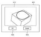
ユーザによるマニュアル操作は、例えば、図15に示すユーザインタフェース400を用いて行なわれる。領域410には、距離センサ300により取得された距離画像が表示されている。ユーザは、例えば、マウスを用いて、領域410内から距離計測用の領域を指定する。全ての領域の指定が済むと、ユーザは、マウスを用いて、OKボタン420を押下する。これにより、ユーザによる距離計測用の領域の指定が完了する。なお、ユーザによりCancelボタン430が押下された場合には、領域の指定が解除される。 The manual operation by the user is performed using, for example, a
ユーザのマニュアル操作に基づいて領域が指定されると、3次元計測装置1は、実施形態4と同様にして照明領域を決定する。具体的には、ユーザにより距離画像上で指定された各領域を、距離センサ300と撮像部150との間の相対的な位置及び姿勢を示す値を用いて撮像部150の画像と同サイズのマスク画像に投影する。なお、マスク画像の各画素は0で初期化しておき、領域が投影された画素の値を1に変更する。全ての対象領域の投影が終われば、マスク画像上で値が1となっている画素の座標を、当該座標及び距離情報に基づいて撮像部150を基準とした3次元座標に変換する。具体的には、距離センサ300と撮像部150との間の相対的な位置及び姿勢を示す値を用いて、距離センサ300により取得された距離画像を撮像部150の座標系における距離画像に変換する。そして、当該変換後の距離画像内の各画素における座標及び距離情報に基づいて3次元座標を生成(変換)する。その後、撮像部150と照明部140との間の相対的な位置及び姿勢を示す値と、照明部140の内部パラメータとに基づいて、当該求めた3次元座標を照明パターンの座標(距離計測用の領域を示す座標)に変換する。これにより、距離計測用の領域が決定する。 When an area is designated based on a user's manual operation, the three-
以上説明したように実施形態5によれば、ユーザのマニュアル操作に基づいて距離計測用の領域を決定する。この場合にも、上述した実施形態1〜4と同様の結果を得ることができる。これにより、自動的に実施された領域分割処理の結果が不適切であったとしても、距離計測用の領域を適切に決定することができる。 As described above, according to the fifth embodiment, the distance measurement region is determined based on the user's manual operation. Also in this case, the same result as in the first to fourth embodiments can be obtained. As a result, even if the result of the automatically performed region division processing is inappropriate, the region for distance measurement can be appropriately determined.
以上が本発明の代表的な実施形態の一例であるが、本発明は、上記及び図面に示す実施形態に限定することなく、その要旨を変更しない範囲内で適宜変形して実施できるものである。 The above is an example of a typical embodiment of the present invention, but the present invention is not limited to the embodiment described above and shown in the drawings, and can be appropriately modified and implemented without departing from the scope of the present invention. .
(変形実施形態1)
また、上述した実施形態1〜5では、マルチスリット光を物体に照射し、スリット光が照射された領域の距離を三角測量により算出する場合について説明したが、距離の算出方法は、この方法に限定されない。例えば、マルチスリット光以外の照明パターン(例えば、単一や複数のスポット光、単一のスリット光、ランダムドットパターン、局所的な平面パターン、空間コード化パターン)を物体に照射し、三角測量により距離を算出するようにしてもよい。また、距離の算出は、三角測量以外にも、例えば、例えば、照明光を物体に照射してから戻ってくるまでの飛行時間を用いて距離を計測する「Time−of−Flight」方式を用いてもよい。また、例えば、人為的に光を投影して距離計測を行なうアクティブ計測ではなく、複数のカメラによって計測対象物体を撮像し、ステレオ法によって距離の算出を行なうパッシブな計測を行なってもよい。その他、計測対象物体の位置及び姿勢の算出に用いるのに足る精度で距離の算出が行なえるのであれば、特にその方法は問わない。(Modified Embodiment 1)
Moreover, although Embodiment 1-5 mentioned above demonstrated the case where a multi slit light was irradiated to an object and the distance of the area | region where the slit light was irradiated is calculated by triangulation, the calculation method of distance is this method. It is not limited. For example, illumination patterns other than multi-slit light (for example, single or multiple spot lights, single slit light, random dot pattern, local plane pattern, spatial coding pattern) are irradiated on the object, and triangulation The distance may be calculated. In addition to triangulation, for example, the distance is calculated using, for example, a “Time-of-Flight” method that measures a distance using a flight time from irradiation of an illumination light to an object and returning. May be. For example, instead of active measurement in which light is artificially projected to measure distance, passive measurement in which a measurement target object is imaged by a plurality of cameras and distance is calculated by a stereo method may be performed. In addition, the method is not particularly limited as long as the distance can be calculated with sufficient accuracy to be used for calculating the position and orientation of the measurement target object.
(変形実施形態2)
また、上述した実施形態1〜5では、撮像部(例えば、カメラ)150の画像面において、マスク画像を作成し、撮像部150と照明部140との間の相対的な位置及び姿勢を示す値を用いて照明パターン(距離計測用の領域)を決めていた。しかし、距離計測用の領域の決定の仕方(照明パターンの作成方法)は、これに限られない。例えば、撮像部150に対する計測対象物体の位置及び姿勢の概略値を照明部140に対する位置及び姿勢に変換し、照明パターンに相当する画像上に3次元形状モデルや領域分割結果を直接投影することによって照明パターンを作成しても良い。この場合、予め校正済みの撮像部150と照明部140との間の相対的な位置及び姿勢と、照明部140の内部パラメータとを用いて3次元形状モデルや領域分割結果を画像上に投影すれば良い。(Modified Embodiment 2)
In
(変形実施形態3)
上述した実施形態1〜3では、計測対象物体の位置及び姿勢の概略値に基づいて3次元形状モデルを画像上に投影し、その投影結果に基づいて距離計測用の領域や、距離計測結果を用いるべき領域を決定していたが、この処理を変形して実施しても良い。これらの領域の決定に際して、計測対象物体の位置及び姿勢の計測精度や、計測対象物体の運動を鑑みても良い。例えば、カルマンフィルタに計測された物体の位置及び姿勢を時系列データとして入力することにより得られる物体の位置及び姿勢の共分散行列を精度の指標として利用しても良い。すなわち、3次元形状モデルを構成する線分の端点を投影する際に、共分散行列の一定の範囲(例えば3σ)に相当する画像上での領域(楕円領域)を算出し、線分ごとに両端点の楕円領域を包含するような領域を設定する。そして、その包含領域では距離の計測は行なわない、又は、距離計測結果を用いないようにする。また、同様にカルマンフィルタを利用し、物体の速度・角速度を推定することにより、物体の位置及び姿勢の概略値が得られた時刻と現在の時刻の差をもとに現在の物体の位置及び姿勢を予測し、その結果に基づいて上述した領域の決定処理を行なっても良い。(Modified Embodiment 3)
In the first to third embodiments described above, a three-dimensional shape model is projected on the image based on the approximate values of the position and orientation of the measurement target object, and the distance measurement region and the distance measurement result are displayed based on the projection result. Although the area to be used has been determined, this process may be modified. In determining these areas, the measurement accuracy of the position and orientation of the measurement target object and the motion of the measurement target object may be taken into consideration. For example, a covariance matrix of the position and orientation of the object obtained by inputting the position and orientation of the object measured by the Kalman filter as time series data may be used as an accuracy index. That is, when projecting the end points of the line segments constituting the three-dimensional shape model, an area (elliptical area) on the image corresponding to a certain range (for example, 3σ) of the covariance matrix is calculated. An area that includes an elliptical area at both end points is set. Then, the distance is not measured in the inclusion area, or the distance measurement result is not used. Similarly, by using the Kalman filter and estimating the object's velocity and angular velocity, the current position and orientation of the object based on the difference between the time when the approximate value of the position and orientation of the object was obtained and the current time. May be predicted, and the region determination process described above may be performed based on the result.
(変形実施形態4)
上述した実施形態1、3〜5では、画像特徴としてエッジ検出する場合について説明したが、画像特徴はエッジに限られない。例えば、非特許文献1に開示されるように、Harrisの検出器を用いて画像から特徴点を検出し、その特徴点に3次元形状モデルの点をあてはめることにより物体の位置及び姿勢を算出しても良い。この場合、距離計測用の(照明)領域の決定に際しては、特徴点の情報を用いる。具体的には、過去に撮像された画像から特徴点を検出し、その特徴点の検出結果に基づいて物体の位置及び姿勢を算出する。そして、その算出結果に基づいて3次元形状モデルを画像上に投影し、その投影像上にある特徴点を選択する。その選択された特徴点の画像座標から一定距離以内では、距離計測用の照明を照射しないように照明パターン(距離計測用の領域)を変更する。(Modified Embodiment 4)
In
(変形実施形態5)
上述した実施形態1〜5では、エッジ、特徴点などの画像特徴が検出され易い領域を判定し、それ以外の領域を距離計測用の領域として決めていたが、この照明領域の決定の仕方はこれに限られない。始めに、濃淡変化に乏しい領域を判定し、その領域を距離計測用の領域として決めても良い。すなわち、物体の位置及び姿勢の概略値に基づいて3次元形状モデルを構成する各面を描画し、これらの領域について距離計測用の照明を照射するよう決定しても良い。また、3次元形状モデルを構成する各面について、予め濃淡変化に乏しいか否かの情報を持たせても良い。この場合、物体の位置及び姿勢の概略値に基づいて3次元形状モデルを描画し、濃淡変化に乏しい面に相当する領域に距離計測用の照明を照射する旨の決定を行なう。以上が、変形実施形態についての説明である。(Modified Embodiment 5)
In
なお、本発明は、例えば、システム、装置、方法、プログラム若しくは記録媒体等としての実施態様を採ることもできる。具体的には、複数の機器から構成されるシステムに適用してもよいし、また、一つの機器からなる装置に適用しても良い。 It should be noted that the present invention can take the form of, for example, a system, apparatus, method, program, or recording medium. Specifically, the present invention may be applied to a system composed of a plurality of devices, or may be applied to an apparatus composed of a single device.
(その他の実施形態)
本発明は、以下の処理を実行することによっても実現される。即ち、上述した実施形態の機能を実現するソフトウェア(プログラム)を、ネットワーク又は各種記憶媒体を介してシステム或いは装置に供給し、そのシステム或いは装置のコンピュータ(又はCPUやMPU等)がプログラムを読み出して実行する処理である。(Other embodiments)
The present invention is also realized by executing the following processing. That is, software (program) that realizes the functions of the above-described embodiments is supplied to a system or apparatus via a network or various storage media, and a computer (or CPU, MPU, etc.) of the system or apparatus reads the program. It is a process to be executed.
Claims (16)
Translated fromJapanese前記計測対象物体の3次元形状を示す情報に基づいて前記計測対象物体における距離計測用の領域を決定する決定手段と、
前記計測対象物体に対して所定の照明パターンを照射する照明手段と、
前記照明手段による照射が行なわれている状態で前記計測対象物体の画像を撮像する撮像手段と、
前記撮像された画像内における前記距離計測用の領域に対応する領域に基づいて前記撮像手段から前記計測対象物体までの距離を示す距離情報を算出する距離算出手段と、
前記距離情報と前記3次元形状モデルとに基づいて前記計測対象物体の位置及び姿勢を算出する位置姿勢算出手段と
を具備することを特徴とする3次元計測装置。Model holding means for holding a three-dimensional shape model of the measurement object;
Determining means for determining an area for distance measurement in the measurement target object based on information indicating a three-dimensional shape of the measurement target object;
Illumination means for irradiating the measurement object with a predetermined illumination pattern;
An imaging unit that captures an image of the measurement target object in a state where irradiation by the illumination unit is performed;
Distance calculating means for calculating distance information indicating a distance from the imaging means to the measurement target object based on an area corresponding to the area for distance measurement in the captured image;
A three-dimensional measurement apparatus comprising: position and orientation calculation means for calculating the position and orientation of the measurement target object based on the distance information and the three-dimensional shape model.
を更に具備し、
前記計測対象物体の3次元形状を示す情報は、前記計測対象物体の前記3次元形状モデルであり、
前記決定手段は、
前記入力手段により入力された概略値を用いて前記3次元形状モデルを投影し、該投影した投影像に基づいて前記距離計測用の領域を決定する
ことを特徴とする請求項1記載の3次元計測装置。An input unit for inputting an approximate value indicating the position and orientation of the measurement target object;
The information indicating the three-dimensional shape of the measurement target object is the three-dimensional shape model of the measurement target object,
The determining means includes
The three-dimensional shape model according to claim 1, wherein the three-dimensional shape model is projected using the approximate value input by the input means, and the distance measurement region is determined based on the projected image. Measuring device.
を更に具備し、
前記位置姿勢算出手段は、
前記画像特徴及び前記距離情報と前記3次元形状モデルとに基づいて前記計測対象物体の位置及び姿勢を算出する
ことを特徴とする請求項1記載の3次元計測装置。Detecting means for detecting image features from a region other than the region corresponding to the distance measurement region in the captured image;
The position / orientation calculation means includes:
The three-dimensional measurement apparatus according to claim 1, wherein the position and orientation of the measurement target object are calculated based on the image feature, the distance information, and the three-dimensional shape model.
前記撮像された画像全体から画像特徴を検出した後、該検出した画像特徴のうち、前記距離計測用の領域に対応する領域以外から検出した画像特徴を出力し、
前記距離算出手段は、
前記撮像された画像全体から距離情報を算出した後、該算出した距離情報のうち、前記距離計測用の領域に対応する領域から算出した距離情報を出力する
ことを特徴とする請求項3記載の3次元計測装置。The detection means includes
After detecting image features from the entire captured image, output image features detected from areas other than the area corresponding to the distance measurement area among the detected image features;
The distance calculating means includes
The distance information calculated from an area corresponding to the area for distance measurement among the calculated distance information is calculated after calculating the distance information from the entire captured image. 3D measuring device.
前記撮像手段により撮像された1枚の画像に基づいて、前記画像特徴の検出及び前記距離情報の算出をそれぞれ行なう
ことを特徴とする請求項4記載の3次元計測装置。The detecting means and the distance calculating means are
The three-dimensional measurement apparatus according to claim 4, wherein the image feature is detected and the distance information is calculated based on a single image captured by the imaging unit.
複数の撮像装置から構成され、
前記距離算出手段は、
前記複数の撮像装置により撮像された複数の画像内における前記距離計測用の領域に対応する領域から前記距離情報をそれぞれ算出し、
前記位置姿勢算出手段は、
前記算出された前記距離情報のそれぞれと前記3次元形状モデルとに基づいて前記計測対象物体の位置及び姿勢を算出する
ことを特徴とする請求項1記載の3次元計測装置。The imaging means includes
Consists of multiple imaging devices,
The distance calculating means includes
Calculating each of the distance information from an area corresponding to the area for distance measurement in a plurality of images captured by the plurality of imaging devices;
The position / orientation calculation means includes:
The three-dimensional measurement apparatus according to claim 1, wherein the position and orientation of the measurement target object are calculated based on each of the calculated distance information and the three-dimensional shape model.
前記決定手段は、
前記距離画像における各画素の距離情報に基づいて該距離画像を領域分割し、前記距離センサと前記撮像手段との間の相対的な位置及び姿勢を示す値を用いて当該分割された領域のいずれかを投影した投影像に基づいて前記距離計測用の領域を決定する
ことを特徴とする請求項1記載の3次元計測装置。The information indicating the three-dimensional shape of the measurement target object is a distance image including the measurement target object acquired by a distance sensor,
The determining means includes
The distance image is divided into regions based on distance information of each pixel in the distance image, and any one of the divided regions using a value indicating a relative position and orientation between the distance sensor and the imaging unit. The three-dimensional measurement apparatus according to claim 1, wherein the distance measurement region is determined based on a projection image obtained by projecting the image.
前記分割された領域の中から所定値以上の面積を持つ領域を投影した投影像に基づいて前記距離計測用の領域を決定する
ことを特徴とする請求項7記載の3次元計測装置。The determining means includes
The three-dimensional measurement apparatus according to claim 7, wherein the distance measurement region is determined based on a projection image obtained by projecting a region having an area greater than or equal to a predetermined value from the divided regions.
前記分割された領域の中からユーザにより指定された領域を投影した投影像に基づいて前記距離計測用の領域を決定する
ことを特徴とする請求項7記載の3次元計測装置。The determining means includes
The three-dimensional measurement apparatus according to claim 7, wherein the distance measurement region is determined based on a projection image obtained by projecting a region specified by a user from the divided regions.
前記計測対象物体において濃淡変化が小さいと推定される領域を前記距離計測用の領域に決定する
ことを特徴とする請求項1記載の3次元計測装置。The determining means includes
The three-dimensional measurement apparatus according to claim 1, wherein an area in which a change in shading is estimated to be small in the measurement target object is determined as the area for distance measurement.
前記計測対象物体の位置及び姿勢を示す概略値を入力する入力手段と、
前記入力手段により入力された概略値を用いて前記3次元形状モデルを投影し、その投影像に基づいて前記計測対象物体における距離計測用の領域を決定する決定手段と、
前記決定手段により決定された領域に対して所定の照明パターンを局所的に照射する照明手段と、
前記照明手段による照射が行なわれている状態で前記計測対象物体の画像を撮像する撮像手段と、
前記撮像された画像内における前記距離計測用の領域に対応する領域に基づいて前記撮像手段から前記計測対象物体までの距離を示す距離情報を算出する距離算出手段と、
前記撮像された画像内における前記距離計測用の領域に対応する領域以外から画像特徴を検出する検出手段と
前記画像特徴及び前記距離情報と前記3次元形状モデルとに基づいて前記計測対象物体の位置及び姿勢を算出する位置姿勢算出手段と
を具備することを特徴とする3次元計測装置。Model holding means for holding a three-dimensional shape model of the measurement object;
Input means for inputting an approximate value indicating the position and orientation of the measurement target object;
Determining means for projecting the three-dimensional shape model using the approximate value input by the input means, and determining an area for distance measurement in the measurement target object based on the projected image;
Illuminating means for locally irradiating a predetermined illumination pattern to the area determined by the determining means;
An imaging unit that captures an image of the measurement target object in a state where irradiation by the illumination unit is performed;
Distance calculating means for calculating distance information indicating a distance from the imaging means to the measurement target object based on an area corresponding to the area for distance measurement in the captured image;
Detection means for detecting an image feature from a region other than the region corresponding to the distance measurement region in the captured image; a position of the measurement target object based on the image feature, the distance information, and the three-dimensional shape model; And a position and orientation calculation means for calculating the orientation.
前記計測対象物体の位置及び姿勢を示す概略値を入力する入力手段と、
前記入力手段により入力された概略値を用いて前記3次元形状モデルを投影し、その投影像に基づいて前記計測対象物体における距離計測用の領域を決定する決定手段と、
前記決定手段により決定された領域に対して所定の照明パターンを局所的に照射する照明手段と、
前記照明手段による照射が行なわれている状態で前記計測対象物体の画像を撮像する複数の撮像手段と、
前記撮像された複数の画像内における前記距離計測用の領域に対応する領域に基づいて前記撮像手段から前記計測対象物体までの距離を示す距離情報をそれぞれ算出する距離算出手段と、
前記複数の画像からそれぞれ算出された前記距離情報と前記3次元形状モデルとに基づいて前記計測対象物体の位置及び姿勢を算出する位置姿勢算出手段と
を具備することを特徴とする3次元計測装置。Model holding means for holding a three-dimensional shape model of the measurement object;
Input means for inputting an approximate value indicating the position and orientation of the measurement target object;
Determining means for projecting the three-dimensional shape model using the approximate value input by the input means, and determining an area for distance measurement in the measurement target object based on the projected image;
Illuminating means for locally irradiating a predetermined illumination pattern to the area determined by the determining means;
A plurality of image pickup means for picking up an image of the measurement target object in a state where irradiation by the illumination means is performed;
Distance calculation means for calculating distance information indicating the distance from the imaging means to the object to be measured based on an area corresponding to the area for distance measurement in the plurality of captured images;
A position / orientation calculation means for calculating a position and orientation of the measurement target object based on the distance information calculated from the plurality of images and the three-dimensional shape model, respectively. .
前記計測対象物体の位置及び姿勢を示す概略値を入力する入力手段と、
前記入力手段により入力された概略値を用いて前記3次元形状モデルを投影し、その投影像に基づいて前記計測対象物体における距離計測用の領域を決定する決定手段と、
前記計測対象物体に向けて所定の照明パターンを局所的に照射する照明手段と、
前記照明手段による照射が行なわれている状態で前記計測対象物体の画像を撮像する撮像手段と、
前記撮像された画像内における前記距離計測用の領域に対応する領域に基づいて前記撮像手段から前記計測対象物体までの距離を示す距離情報を算出するとともに、前記決定手段による決定結果に基づいて当該算出した距離情報を出力する距離算出手段と、
前記撮像された画像に基づいて前記計測対象物体の画像特徴を検出するとともに、前記決定手段による決定結果に基づいて当該検出した画像特徴を出力する検出手段と、
前記画像特徴及び前記距離情報と前記3次元形状モデルとに基づいて前記計測対象物体の位置及び姿勢を算出する位置姿勢算出手段と
を具備することを特徴とする3次元計測装置。Model holding means for holding a three-dimensional shape model of the measurement object;
Input means for inputting an approximate value indicating the position and orientation of the measurement target object;
Determining means for projecting the three-dimensional shape model using the approximate value input by the input means, and determining an area for distance measurement in the measurement target object based on the projected image;
Illumination means for locally irradiating a predetermined illumination pattern toward the measurement target object;
An imaging unit that captures an image of the measurement target object in a state where irradiation by the illumination unit is performed;
Based on a region corresponding to the region for distance measurement in the captured image, distance information indicating a distance from the imaging unit to the measurement target object is calculated, and based on a determination result by the determination unit A distance calculating means for outputting the calculated distance information;
Detecting means for detecting an image feature of the measurement target object based on the captured image, and outputting the detected image feature based on a determination result by the determining means;
A three-dimensional measurement apparatus comprising: a position / orientation calculation unit that calculates the position and orientation of the measurement target object based on the image feature, the distance information, and the three-dimensional shape model.
距離センサにより取得された前記計測対象物体を含む距離画像に基づいて前記計測対象物体における距離計測用の領域を決定する決定手段と、
前記決定手段により決定された領域に対して所定の照明パターンを局所的に照射する照明手段と、
前記照明手段による照射が行なわれている状態で前記計測対象物体の画像を撮像する撮像手段と、
前記撮像された画像内における前記距離計測用の領域に対応する領域に基づいて前記撮像手段から前記計測対象物体までの距離を示す距離情報を算出する距離算出手段と、
前記撮像された画像内における前記距離計測用の領域に対応する領域以外から画像特徴を検出する検出手段と
前記画像特徴及び前記距離情報と前記3次元形状モデルとに基づいて前記計測対象物体の位置及び姿勢を算出する位置姿勢算出手段と
を具備し、
前記決定手段は、
前記距離画像における各画素の距離情報に基づいて該距離画像を領域分割し、前記距離センサと前記撮像手段との間の相対的な位置及び姿勢を示す値を用いて当該分割された領域のいずれかを投影した投影像に基づいて前記距離計測用の領域を決定する
ことを特徴とする3次元計測装置。Model holding means for holding a three-dimensional shape model of the measurement object;
Determining means for determining a region for distance measurement in the measurement target object based on a distance image including the measurement target object acquired by a distance sensor;
Illuminating means for locally irradiating a predetermined illumination pattern to the area determined by the determining means;
An imaging unit that captures an image of the measurement target object in a state where irradiation by the illumination unit is performed;
Distance calculating means for calculating distance information indicating a distance from the imaging means to the measurement target object based on an area corresponding to the area for distance measurement in the captured image;
Detecting means for detecting an image feature from a region other than the region corresponding to the distance measurement region in the captured image; a position of the measurement target object based on the image feature, the distance information, and the three-dimensional shape model; And position and orientation calculation means for calculating the orientation,
The determining means includes
The distance image is divided into regions based on distance information of each pixel in the distance image, and any one of the divided regions using a value indicating a relative position and orientation between the distance sensor and the imaging unit. A distance measurement region is determined based on a projection image obtained by projecting the image.
決定手段が、前記計測対象物体の3次元形状を示す情報に基づいて前記計測対象物体における距離計測用の領域を決定する工程と、
照明手段が、前記計測対象物体に対して所定の照明パターンを照射する工程と、
撮像手段が、前記照明手段による照射が行なわれている状態で前記計測対象物体の画像を撮像する工程と、
距離算出手段が、前記撮像された画像内における前記距離計測用の領域に対応する領域に基づいて前記撮像手段から前記計測対象物体までの距離を示す距離情報を算出する工程と、
位置姿勢算出手段が、前記距離情報と前記3次元形状モデルとに基づいて前記計測対象物体の位置及び姿勢を算出する工程と
を含むことを特徴とする計測方法。A measurement method of a three-dimensional measurement apparatus that measures the position and orientation of a measurement target object using a three-dimensional shape model of the measurement target object,
A step of determining a distance measurement region in the measurement target object based on information indicating a three-dimensional shape of the measurement target object;
Illuminating means irradiating a predetermined illumination pattern to the measurement object;
An image capturing unit that captures an image of the measurement target object in a state where irradiation by the illumination unit is performed;
A step of calculating distance information indicating a distance from the imaging unit to the measurement target object based on a region corresponding to the region for distance measurement in the captured image;
A position and orientation calculation means includes a step of calculating the position and orientation of the measurement target object based on the distance information and the three-dimensional shape model.
計測対象物体の3次元形状モデルを保持するモデル保持手段、
前記計測対象物体の3次元形状を示す情報に基づいて前記計測対象物体における距離計測用の領域を決定する決定手段、
前記計測対象物体に対して所定の照明パターンを照射する照明手段、
前記照明手段による照射が行なわれている状態で前記計測対象物体の画像を撮像する撮像手段、
前記撮像された画像内における前記距離計測用の領域に対応する領域に基づいて前記撮像手段から前記計測対象物体までの距離を示す距離情報を算出する距離算出手段、
前記距離情報と前記3次元形状モデルとに基づいて前記計測対象物体の位置及び姿勢を算出する位置姿勢算出手段
として機能させるためのプログラム。Computer
Model holding means for holding a three-dimensional shape model of the measurement object;
Determining means for determining a distance measurement region in the measurement target object based on information indicating a three-dimensional shape of the measurement target object;
Illumination means for irradiating the measurement object with a predetermined illumination pattern,
An imaging unit that captures an image of the object to be measured in a state where irradiation by the illumination unit is performed;
Distance calculating means for calculating distance information indicating a distance from the imaging means to the measurement target object based on an area corresponding to the area for distance measurement in the imaged image;
A program for functioning as a position / orientation calculation unit that calculates the position and orientation of the measurement target object based on the distance information and the three-dimensional shape model.
Priority Applications (1)
| Application Number | Priority Date | Filing Date | Title |
|---|---|---|---|
| JP2010137680AJP5567908B2 (en) | 2009-06-24 | 2010-06-16 | Three-dimensional measuring apparatus, measuring method and program |
Applications Claiming Priority (3)
| Application Number | Priority Date | Filing Date | Title |
|---|---|---|---|
| JP2009150323 | 2009-06-24 | ||
| JP2009150323 | 2009-06-24 | ||
| JP2010137680AJP5567908B2 (en) | 2009-06-24 | 2010-06-16 | Three-dimensional measuring apparatus, measuring method and program |
Publications (3)
| Publication Number | Publication Date |
|---|---|
| JP2011027724Atrue JP2011027724A (en) | 2011-02-10 |
| JP2011027724A5 JP2011027724A5 (en) | 2013-08-01 |
| JP5567908B2 JP5567908B2 (en) | 2014-08-06 |
Family
ID=43380369
Family Applications (1)
| Application Number | Title | Priority Date | Filing Date |
|---|---|---|---|
| JP2010137680AActiveJP5567908B2 (en) | 2009-06-24 | 2010-06-16 | Three-dimensional measuring apparatus, measuring method and program |
Country Status (2)
| Country | Link |
|---|---|
| US (1) | US9025857B2 (en) |
| JP (1) | JP5567908B2 (en) |
Cited By (15)
| Publication number | Priority date | Publication date | Assignee | Title |
|---|---|---|---|---|
| JP2013019890A (en)* | 2011-06-13 | 2013-01-31 | Canon Inc | Information processor and information processing method |
| JP2013036988A (en)* | 2011-07-08 | 2013-02-21 | Canon Inc | Information processing apparatus and information processing method |
| JP2013036987A (en)* | 2011-07-08 | 2013-02-21 | Canon Inc | Information processing device and information processing method |
| JP2014002033A (en)* | 2012-06-18 | 2014-01-09 | Canon Inc | Image process device and image process method |
| WO2014064990A1 (en)* | 2012-10-25 | 2014-05-01 | シャープ株式会社 | Plane detection device, autonomous locomotion device provided with plane detection device, method for detecting road level difference, device for detecting road level difference, and vehicle provided with device for detecting road level difference |
| JP2014085940A (en)* | 2012-10-25 | 2014-05-12 | Sharp Corp | Plane detection device and autonomous moving device including the same |
| JP2014106099A (en)* | 2012-11-27 | 2014-06-09 | Keyence Corp | Shape measurement device, shape measurement method, and shape measurement program |
| JP2014524016A (en)* | 2011-06-24 | 2014-09-18 | ソフトキネティック ソフトウェア | Improved depth measurement quality |
| US9141873B2 (en) | 2011-12-27 | 2015-09-22 | Canon Kabushiki Kaisha | Apparatus for measuring three-dimensional position, method thereof, and program |
| JP2015212942A (en)* | 2014-04-25 | 2015-11-26 | グーグル インコーポレイテッド | Methods and systems for object detection using laser point clouds |
| JP2016509394A (en)* | 2012-12-28 | 2016-03-24 | メタイオ ゲゼルシャフト ミット ベシュレンクテル ハフツングmetaio GmbH | Method and system for projecting digital information on a real object in a real environment |
| JP2016109671A (en)* | 2014-12-01 | 2016-06-20 | キヤノン株式会社 | Three-dimensional measuring apparatus and control method therefor |
| WO2022190534A1 (en)* | 2021-03-10 | 2022-09-15 | オムロン株式会社 | Recognition device, robot control system, recognition method and program |
| WO2023238741A1 (en)* | 2022-06-07 | 2023-12-14 | ソニーセミコンダクタソリューションズ株式会社 | Photodetection device, system, and information processing device |
| WO2025143023A1 (en)* | 2023-12-28 | 2025-07-03 | Scivax株式会社 | Modeling device, modeling method, and modeling program |
Families Citing this family (38)
| Publication number | Priority date | Publication date | Assignee | Title |
|---|---|---|---|---|
| US9879976B2 (en) | 2010-01-20 | 2018-01-30 | Faro Technologies, Inc. | Articulated arm coordinate measurement machine that uses a 2D camera to determine 3D coordinates of smoothly continuous edge features |
| US9607239B2 (en) | 2010-01-20 | 2017-03-28 | Faro Technologies, Inc. | Articulated arm coordinate measurement machine having a 2D camera and method of obtaining 3D representations |
| JP5624394B2 (en) | 2010-07-16 | 2014-11-12 | キヤノン株式会社 | Position / orientation measurement apparatus, measurement processing method thereof, and program |
| TWI420081B (en)* | 2010-07-27 | 2013-12-21 | Pixart Imaging Inc | Distance measuring system and distance measuring method |
| JP5671281B2 (en) | 2010-08-20 | 2015-02-18 | キヤノン株式会社 | Position / orientation measuring apparatus, control method and program for position / orientation measuring apparatus |
| JP5839971B2 (en)* | 2010-12-14 | 2016-01-06 | キヤノン株式会社 | Information processing apparatus, information processing method, and program |
| JP5138119B2 (en)* | 2011-04-25 | 2013-02-06 | 三洋電機株式会社 | Object detection device and information acquisition device |
| US8447443B1 (en) | 2011-06-21 | 2013-05-21 | The United States Of America As Represented By The Administrator Of The National Aeronautics And Space Administration | Systems and methods for peak-seeking control |
| JP6004809B2 (en) | 2012-03-13 | 2016-10-12 | キヤノン株式会社 | Position / orientation estimation apparatus, information processing apparatus, and information processing method |
| US8690063B2 (en)* | 2012-05-01 | 2014-04-08 | Symbol Technologies, Inc. | Apparatus for and method of electro-optically reading direct part marking indicia by image capture |
| JP5818773B2 (en)* | 2012-11-22 | 2015-11-18 | キヤノン株式会社 | Image processing apparatus, image processing method, and program |
| JP2014185996A (en)* | 2013-03-25 | 2014-10-02 | Toshiba Corp | Measurement device |
| CN104344795A (en)* | 2013-07-24 | 2015-02-11 | 鸿富锦精密工业(深圳)有限公司 | Point cloud profile measuring system and method |
| CN104424655A (en)* | 2013-09-10 | 2015-03-18 | 鸿富锦精密工业(深圳)有限公司 | System and method for reconstructing point cloud curved surface |
| JP6253368B2 (en) | 2013-11-25 | 2017-12-27 | キヤノン株式会社 | Three-dimensional shape measuring apparatus and control method thereof |
| US9747680B2 (en) | 2013-11-27 | 2017-08-29 | Industrial Technology Research Institute | Inspection apparatus, method, and computer program product for machine vision inspection |
| JP6351243B2 (en)* | 2013-11-28 | 2018-07-04 | キヤノン株式会社 | Image processing apparatus and image processing method |
| US9233469B2 (en)* | 2014-02-13 | 2016-01-12 | GM Global Technology Operations LLC | Robotic system with 3D box location functionality |
| JP6317618B2 (en)* | 2014-05-01 | 2018-04-25 | キヤノン株式会社 | Information processing apparatus and method, measuring apparatus, and working apparatus |
| US9875535B2 (en)* | 2016-02-11 | 2018-01-23 | Caterpillar Inc. | Wear measurement system using computer vision |
| US9880075B2 (en)* | 2016-02-11 | 2018-01-30 | Caterpillar Inc. | Wear measurement system using a computer model |
| WO2017199088A1 (en)* | 2016-05-19 | 2017-11-23 | Vermeer International B.V. | Bale detection and classification using stereo cameras |
| JP6420404B1 (en)* | 2017-04-26 | 2018-11-07 | ファナック株式会社 | Object recognition device |
| JP7078056B2 (en)* | 2017-11-30 | 2022-05-31 | 株式会社ニコン | Detection device, processing device, attachment, detection method, and detection program |
| CN108305237B (en)* | 2018-01-23 | 2021-09-21 | 中国科学院遥感与数字地球研究所 | Multi-stereo image fusion drawing method considering different illumination imaging conditions |
| US11896461B2 (en) | 2018-06-22 | 2024-02-13 | Align Technology, Inc. | Intraoral 3D scanner employing multiple miniature cameras and multiple miniature pattern projectors |
| KR102570059B1 (en)* | 2018-08-16 | 2023-08-23 | 엘지이노텍 주식회사 | Method and apparatus for sensing |
| JP7233261B2 (en)* | 2019-03-13 | 2023-03-06 | キヤノン株式会社 | Three-dimensional surveying device, imaging device, control method and program |
| JP2020153718A (en)* | 2019-03-18 | 2020-09-24 | 株式会社リコー | Measuring equipment and modeling equipment |
| JP7630947B2 (en)* | 2020-10-05 | 2025-02-18 | キヤノン株式会社 | Three-dimensional measurement device, system, and production method |
| JP7163947B2 (en)* | 2020-10-22 | 2022-11-01 | セイコーエプソン株式会社 | Projection area setting support method, setting support system, and program |
| CN113421245A (en)* | 2021-06-27 | 2021-09-21 | 王程 | Three-dimensional surface roughness calculation method for color reproduction |
| CN114049376B (en)* | 2021-09-17 | 2024-12-10 | 北京航空航天大学 | Method, device, computer-readable medium and program product for real-time posture tracking |
| EP4332499A1 (en)* | 2022-08-30 | 2024-03-06 | Canon Kabushiki Kaisha | Three-dimensional measuring apparatus, three-dimensional measuring method, storage medium, system, and method for manufacturing an article |
| USD1069851S1 (en) | 2022-12-02 | 2025-04-08 | Vermeer Manufacturing Company | Bale mover |
| US12372967B2 (en)* | 2023-08-23 | 2025-07-29 | Locus Robotics Corp. | Visual robot pose estimation |
| CN117470122B (en)* | 2023-11-08 | 2024-07-30 | 华中科技大学 | An automatic inspection device for steel bar skeleton binding quality |
| CN119714123B (en)* | 2024-11-27 | 2025-10-03 | 浙江大学 | Multi-view line laser scanning device based on binocular stereoscopic vision and complex surface panoramic measurement method |
Citations (7)
| Publication number | Priority date | Publication date | Assignee | Title |
|---|---|---|---|---|
| JP2001143073A (en)* | 1999-11-10 | 2001-05-25 | Nippon Telegr & Teleph Corp <Ntt> | How to determine the position and orientation of an object |
| JP2006300929A (en)* | 2005-03-22 | 2006-11-02 | Jfe Engineering Kk | Object three-dimensional position recognition apparatus and depalletizing system |
| WO2006120759A1 (en)* | 2005-05-12 | 2006-11-16 | Techno Dream 21 Co., Ltd. | 3-dimensional shape measuring method and device thereof |
| JP2008046750A (en)* | 2006-08-11 | 2008-02-28 | Canon Inc | Image processing apparatus and method |
| JP2008217544A (en)* | 2007-03-06 | 2008-09-18 | Yaskawa Electric Corp | Object detection method, object detection apparatus, and robot equipped with the same |
| JP2009014415A (en)* | 2007-07-02 | 2009-01-22 | National Institute Of Advanced Industrial & Technology | Object recognition apparatus and object recognition method |
| JP2009129189A (en)* | 2007-11-22 | 2009-06-11 | Ihi Corp | Object recognition method |
Family Cites Families (52)
| Publication number | Priority date | Publication date | Assignee | Title |
|---|---|---|---|---|
| JP3749369B2 (en)* | 1997-03-21 | 2006-02-22 | 株式会社竹中工務店 | Hand pointing device |
| US5893085A (en)* | 1997-06-10 | 1999-04-06 | Phillips; Ronald W. | Dynamic fuzzy logic process for identifying objects in three-dimensional data |
| US6204916B1 (en)* | 1998-02-03 | 2001-03-20 | Minolta Co., Ltd. | Three dimensional information measurement method and apparatus |
| US6549647B1 (en)* | 2000-01-07 | 2003-04-15 | Cyberoptics Corporation | Inspection system with vibration resistant video capture |
| EP1143372B1 (en)* | 2000-04-06 | 2006-03-22 | Seiko Epson Corporation | Method of and apparatus for reading a two-dimensional bar code symbol and data storage medium |
| JP2002191058A (en)* | 2000-12-20 | 2002-07-05 | Olympus Optical Co Ltd | Three-dimensional image acquisition device and three- dimensional image acquisition method |
| US7072502B2 (en)* | 2001-06-07 | 2006-07-04 | Applied Materials, Inc. | Alternating phase-shift mask inspection method and apparatus |
| US20030123707A1 (en)* | 2001-12-31 | 2003-07-03 | Park Seujeung P. | Imaging-based distance measurement and three-dimensional profiling system |
| JP3796449B2 (en)* | 2002-01-31 | 2006-07-12 | キヤノン株式会社 | Position and orientation determination method and apparatus, and computer program |
| EP1349114A3 (en)* | 2002-03-19 | 2011-06-15 | Canon Kabushiki Kaisha | Sensor calibration apparatus, sensor calibration method, program, storage medium, information processing method, and information processing apparatus |
| WO2003081536A1 (en)* | 2002-03-26 | 2003-10-02 | So-Woon Kim | System and method for 3-dimension simulation of glasses |
| US7440590B1 (en)* | 2002-05-21 | 2008-10-21 | University Of Kentucky Research Foundation | System and technique for retrieving depth information about a surface by projecting a composite image of modulated light patterns |
| JP3859571B2 (en)* | 2002-10-17 | 2006-12-20 | ファナック株式会社 | 3D visual sensor |
| JP3953988B2 (en)* | 2003-07-29 | 2007-08-08 | Tdk株式会社 | Inspection apparatus and inspection method |
| AU2004273275A1 (en)* | 2003-08-29 | 2005-03-24 | Nec Corporation | Object posture estimation/correlation system using weight information |
| US7028723B1 (en)* | 2003-11-03 | 2006-04-18 | Alouani Ali Tahar | Apparatus and method for automatic prescription verification |
| DE10359415A1 (en)* | 2003-12-16 | 2005-07-14 | Trimble Jena Gmbh | Method for calibrating a surveying device |
| JP3779308B2 (en)* | 2004-07-21 | 2006-05-24 | 独立行政法人科学技術振興機構 | Camera calibration system and three-dimensional measurement system |
| EP1792282B1 (en)* | 2004-08-30 | 2010-07-21 | Commonwealth Scientific And Industrial Research Organisation | A method for automated 3d imaging |
| KR100601967B1 (en)* | 2004-10-08 | 2006-07-18 | 삼성전자주식회사 | Dynamic Range Compression Device and Method of Image |
| WO2006062132A1 (en)* | 2004-12-07 | 2006-06-15 | The University Of Tokyo | Stereoscopic image reconfiguration device, stereoscopic image reconfiguration method, and stereoscopic image reconfiguration program |
| WO2006078902A2 (en)* | 2005-01-19 | 2006-07-27 | Dermaspect, Llc | Devices and methods for identifying and monitoring changes of a suspect area on a patient |
| JP4599184B2 (en)* | 2005-02-02 | 2010-12-15 | キヤノン株式会社 | Index placement measurement method, index placement measurement device |
| US7136765B2 (en)* | 2005-02-09 | 2006-11-14 | Deepsea Power & Light, Inc. | Buried object locating and tracing method and system employing principal components analysis for blind signal detection |
| US7505152B2 (en)* | 2005-02-24 | 2009-03-17 | The Boeing Company | Optical metrology system |
| DE102005029901B4 (en)* | 2005-06-25 | 2022-10-06 | Modi Modular Digits Gmbh | Device and method for visually detecting two-dimensional or three-dimensional objects |
| JP4914039B2 (en)* | 2005-07-27 | 2012-04-11 | キヤノン株式会社 | Information processing method and apparatus |
| US7301165B2 (en)* | 2005-10-24 | 2007-11-27 | General Electric Company | Methods and apparatus for inspecting an object |
| JP5063023B2 (en)* | 2006-03-31 | 2012-10-31 | キヤノン株式会社 | Position / orientation correction apparatus and position / orientation correction method |
| US7925049B2 (en)* | 2006-08-15 | 2011-04-12 | Sri International | Stereo-based visual odometry method and system |
| US20080075234A1 (en)* | 2006-09-21 | 2008-03-27 | Bruker Axs, Inc. | Method and apparatus for increasing x-ray flux and brightness of a rotating anode x-ray source |
| JP4403172B2 (en)* | 2006-12-22 | 2010-01-20 | 富士フイルム株式会社 | File generation method and apparatus, and stereoscopic image display control method and apparatus |
| EP2085744B1 (en)* | 2006-12-25 | 2016-11-23 | NEC Corporation | Distance measuring device, method, and program |
| CN101617197B (en)* | 2007-02-16 | 2011-06-22 | 三菱电机株式会社 | Measuring device, measuring method and ground feature recognition device |
| US8218903B2 (en)* | 2007-04-24 | 2012-07-10 | Sony Computer Entertainment Inc. | 3D object scanning using video camera and TV monitor |
| US20080309913A1 (en)* | 2007-06-14 | 2008-12-18 | James John Fallon | Systems and methods for laser radar imaging for the blind and visually impaired |
| US8737684B2 (en)* | 2007-11-30 | 2014-05-27 | Searidge Technologies Inc. | Airport target tracking system |
| JP5111210B2 (en)* | 2008-04-09 | 2013-01-09 | キヤノン株式会社 | Image processing apparatus and image processing method |
| US8559699B2 (en)* | 2008-10-10 | 2013-10-15 | Roboticvisiontech Llc | Methods and apparatus to facilitate operations in image based systems |
| WO2010042953A1 (en)* | 2008-10-10 | 2010-04-15 | Gesturetek, Inc. | Single camera tracker |
| KR101251372B1 (en)* | 2008-10-13 | 2013-04-05 | 주식회사 고영테크놀러지 | Three dimension shape measuring method |
| JP2010134649A (en)* | 2008-12-03 | 2010-06-17 | Canon Inc | Information processing apparatus, its processing method, and program |
| JP5310130B2 (en)* | 2009-03-11 | 2013-10-09 | オムロン株式会社 | Display method of recognition result by three-dimensional visual sensor and three-dimensional visual sensor |
| JP2010210585A (en)* | 2009-03-12 | 2010-09-24 | Omron Corp | Model display method in three-dimensional visual sensor, and three-dimensional visual sensor |
| TWI392864B (en)* | 2009-04-03 | 2013-04-11 | Ind Tech Res Inst | Optical inspection apparatus |
| JP5388932B2 (en)* | 2009-04-30 | 2014-01-15 | キヤノン株式会社 | Information processing apparatus and control method thereof |
| JP5290864B2 (en)* | 2009-05-18 | 2013-09-18 | キヤノン株式会社 | Position and orientation estimation apparatus and method |
| JP5333344B2 (en)* | 2009-06-19 | 2013-11-06 | 株式会社安川電機 | Shape detection apparatus and robot system |
| US20110069204A1 (en)* | 2009-09-23 | 2011-03-24 | Zoran Corporation | Method and apparatus for image correction |
| US8306314B2 (en)* | 2009-12-28 | 2012-11-06 | Mitsubishi Electric Research Laboratories, Inc. | Method and system for determining poses of objects |
| JP5170154B2 (en)* | 2010-04-26 | 2013-03-27 | オムロン株式会社 | Shape measuring apparatus and calibration method |
| US8334985B2 (en)* | 2010-10-08 | 2012-12-18 | Omron Corporation | Shape measuring apparatus and shape measuring method |
- 2010
- 2010-06-16JPJP2010137680Apatent/JP5567908B2/enactiveActive
- 2010-06-18USUS12/818,538patent/US9025857B2/enactiveActive
Patent Citations (7)
| Publication number | Priority date | Publication date | Assignee | Title |
|---|---|---|---|---|
| JP2001143073A (en)* | 1999-11-10 | 2001-05-25 | Nippon Telegr & Teleph Corp <Ntt> | How to determine the position and orientation of an object |
| JP2006300929A (en)* | 2005-03-22 | 2006-11-02 | Jfe Engineering Kk | Object three-dimensional position recognition apparatus and depalletizing system |
| WO2006120759A1 (en)* | 2005-05-12 | 2006-11-16 | Techno Dream 21 Co., Ltd. | 3-dimensional shape measuring method and device thereof |
| JP2008046750A (en)* | 2006-08-11 | 2008-02-28 | Canon Inc | Image processing apparatus and method |
| JP2008217544A (en)* | 2007-03-06 | 2008-09-18 | Yaskawa Electric Corp | Object detection method, object detection apparatus, and robot equipped with the same |
| JP2009014415A (en)* | 2007-07-02 | 2009-01-22 | National Institute Of Advanced Industrial & Technology | Object recognition apparatus and object recognition method |
| JP2009129189A (en)* | 2007-11-22 | 2009-06-11 | Ihi Corp | Object recognition method |
Cited By (19)
| Publication number | Priority date | Publication date | Assignee | Title |
|---|---|---|---|---|
| JP2013019890A (en)* | 2011-06-13 | 2013-01-31 | Canon Inc | Information processor and information processing method |
| JP2014524016A (en)* | 2011-06-24 | 2014-09-18 | ソフトキネティック ソフトウェア | Improved depth measurement quality |
| JP2013036988A (en)* | 2011-07-08 | 2013-02-21 | Canon Inc | Information processing apparatus and information processing method |
| JP2013036987A (en)* | 2011-07-08 | 2013-02-21 | Canon Inc | Information processing device and information processing method |
| US9437005B2 (en) | 2011-07-08 | 2016-09-06 | Canon Kabushiki Kaisha | Information processing apparatus and information processing method |
| US9141873B2 (en) | 2011-12-27 | 2015-09-22 | Canon Kabushiki Kaisha | Apparatus for measuring three-dimensional position, method thereof, and program |
| JP2014002033A (en)* | 2012-06-18 | 2014-01-09 | Canon Inc | Image process device and image process method |
| US10203197B2 (en) | 2012-06-18 | 2019-02-12 | Canon Kabushiki Kaisha | Range measurement apparatus and range measurement method |
| JP2014085940A (en)* | 2012-10-25 | 2014-05-12 | Sharp Corp | Plane detection device and autonomous moving device including the same |
| WO2014064990A1 (en)* | 2012-10-25 | 2014-05-01 | シャープ株式会社 | Plane detection device, autonomous locomotion device provided with plane detection device, method for detecting road level difference, device for detecting road level difference, and vehicle provided with device for detecting road level difference |
| JP2014106099A (en)* | 2012-11-27 | 2014-06-09 | Keyence Corp | Shape measurement device, shape measurement method, and shape measurement program |
| JP2016509394A (en)* | 2012-12-28 | 2016-03-24 | メタイオ ゲゼルシャフト ミット ベシュレンクテル ハフツングmetaio GmbH | Method and system for projecting digital information on a real object in a real environment |
| JP2015212942A (en)* | 2014-04-25 | 2015-11-26 | グーグル インコーポレイテッド | Methods and systems for object detection using laser point clouds |
| JP2016109671A (en)* | 2014-12-01 | 2016-06-20 | キヤノン株式会社 | Three-dimensional measuring apparatus and control method therefor |
| WO2022190534A1 (en)* | 2021-03-10 | 2022-09-15 | オムロン株式会社 | Recognition device, robot control system, recognition method and program |
| JP2022138329A (en)* | 2021-03-10 | 2022-09-26 | オムロン株式会社 | Recognition device, robot control system, recognition method, and program |
| JP7643096B2 (en) | 2021-03-10 | 2025-03-11 | オムロン株式会社 | Recognition device, robot control system, recognition method, and program |
| WO2023238741A1 (en)* | 2022-06-07 | 2023-12-14 | ソニーセミコンダクタソリューションズ株式会社 | Photodetection device, system, and information processing device |
| WO2025143023A1 (en)* | 2023-12-28 | 2025-07-03 | Scivax株式会社 | Modeling device, modeling method, and modeling program |
Also Published As
| Publication number | Publication date |
|---|---|
| US9025857B2 (en) | 2015-05-05 |
| JP5567908B2 (en) | 2014-08-06 |
| US20100328682A1 (en) | 2010-12-30 |
Similar Documents
| Publication | Publication Date | Title |
|---|---|---|
| JP5567908B2 (en) | Three-dimensional measuring apparatus, measuring method and program | |
| JP5839971B2 (en) | Information processing apparatus, information processing method, and program | |
| US20200096317A1 (en) | Three-dimensional measurement apparatus, processing method, and non-transitory computer-readable storage medium | |
| JP6370038B2 (en) | Position and orientation measurement apparatus and method | |
| JP5839929B2 (en) | Information processing apparatus, information processing system, information processing method, and program | |
| US9279661B2 (en) | Information processing apparatus and information processing method | |
| JP5393318B2 (en) | Position and orientation measurement method and apparatus | |
| JP6271953B2 (en) | Image processing apparatus and image processing method | |
| JP6092530B2 (en) | Image processing apparatus and image processing method | |
| JP6324025B2 (en) | Information processing apparatus and information processing method | |
| JP6677522B2 (en) | Information processing apparatus, control method for information processing apparatus, and program | |
| JP6626338B2 (en) | Information processing apparatus, control method for information processing apparatus, and program | |
| JP2016170050A (en) | Position / orientation measuring apparatus, position / orientation measuring method, and computer program | |
| JP5976089B2 (en) | Position / orientation measuring apparatus, position / orientation measuring method, and program | |
| JP6180158B2 (en) | Position / orientation measuring apparatus, control method and program for position / orientation measuring apparatus | |
| JP6040264B2 (en) | Information processing apparatus, information processing apparatus control method, and program | |
| JP5698815B2 (en) | Information processing apparatus, information processing apparatus control method, and program | |
| JP2015132523A (en) | Position/attitude measurement apparatus, position/attitude measurement method, and program | |
| JP6890422B2 (en) | Information processing equipment, control methods and programs for information processing equipment | |
| JP6285765B2 (en) | Information processing apparatus and information processing method | |
| JP6766229B2 (en) | Position and posture measuring device and method |
Legal Events
| Date | Code | Title | Description |
|---|---|---|---|
| A521 | Written amendment | Free format text:JAPANESE INTERMEDIATE CODE: A523 Effective date:20130617 | |
| A621 | Written request for application examination | Free format text:JAPANESE INTERMEDIATE CODE: A621 Effective date:20130617 | |
| A977 | Report on retrieval | Free format text:JAPANESE INTERMEDIATE CODE: A971007 Effective date:20140127 | |
| A131 | Notification of reasons for refusal | Free format text:JAPANESE INTERMEDIATE CODE: A131 Effective date:20140228 | |
| A521 | Written amendment | Free format text:JAPANESE INTERMEDIATE CODE: A523 Effective date:20140326 | |
| TRDD | Decision of grant or rejection written | ||
| A01 | Written decision to grant a patent or to grant a registration (utility model) | Free format text:JAPANESE INTERMEDIATE CODE: A01 Effective date:20140523 | |
| A61 | First payment of annual fees (during grant procedure) | Free format text:JAPANESE INTERMEDIATE CODE: A61 Effective date:20140620 | |
| R151 | Written notification of patent or utility model registration | Ref document number:5567908 Country of ref document:JP Free format text:JAPANESE INTERMEDIATE CODE: R151 |