JP2011021855A - Control method of refrigerator - Google Patents
Control method of refrigeratorDownload PDFInfo
- Publication number
- JP2011021855A JP2011021855AJP2009169296AJP2009169296AJP2011021855AJP 2011021855 AJP2011021855 AJP 2011021855AJP 2009169296 AJP2009169296 AJP 2009169296AJP 2009169296 AJP2009169296 AJP 2009169296AJP 2011021855 AJP2011021855 AJP 2011021855A
- Authority
- JP
- Japan
- Prior art keywords
- refrigerator
- condition
- stage
- heat
- reduction
- Prior art date
- Legal status (The legal status is an assumption and is not a legal conclusion. Google has not performed a legal analysis and makes no representation as to the accuracy of the status listed.)
- Granted
Links
- 238000000034methodMethods0.000titleclaimsdescription43
- XLYOFNOQVPJJNP-UHFFFAOYSA-NwaterSubstancesOXLYOFNOQVPJJNP-UHFFFAOYSA-N0.000claimsabstractdescription100
- 230000007423decreaseEffects0.000claimsabstractdescription35
- 238000004378air conditioningMethods0.000claimsabstractdescription29
- 230000003247decreasing effectEffects0.000claimsabstractdescription3
- 239000000498cooling waterSubstances0.000claimsdescription30
- 238000001816coolingMethods0.000claimsdescription29
- 238000007710freezingMethods0.000claimsdescription23
- 230000008014freezingEffects0.000claimsdescription23
- 230000000593degrading effectEffects0.000claimsdescription2
- 238000005057refrigerationMethods0.000description21
- 238000004519manufacturing processMethods0.000description12
- 238000009434installationMethods0.000description4
- 238000010586diagramMethods0.000description3
- 230000000694effectsEffects0.000description3
- 238000002474experimental methodMethods0.000description3
- NAWXUBYGYWOOIX-SFHVURJKSA-N(2s)-2-[[4-[2-(2,4-diaminoquinazolin-6-yl)ethyl]benzoyl]amino]-4-methylidenepentanedioic acidChemical compoundC1=CC2=NC(N)=NC(N)=C2C=C1CCC1=CC=C(C(=O)N[C@@H](CC(=C)C(O)=O)C(O)=O)C=C1NAWXUBYGYWOOIX-SFHVURJKSA-N0.000description1
- 206010037660PyrexiaDiseases0.000description1
- 238000001514detection methodMethods0.000description1
- 238000004088simulationMethods0.000description1
Images


Landscapes
- Air Conditioning Control Device (AREA)
Abstract
Description
Translated fromJapanese本発明は、空調システムにおいて複数の冷凍機を増段又は減段して冷凍機を台数制御する技術に関する。 The present invention relates to a technique for controlling the number of refrigerators by increasing or decreasing a plurality of refrigerators in an air conditioning system.
特許文献1では、冷凍機の定格流量を基に、増段する制御を行っている。具体的には、二次側設備の二次側流量が、冷凍機の定格流量の合計値である一次側流量よりも大きい場合、熱源機の運転台数を増段している。 In Patent Document 1, control to increase the stage is performed based on the rated flow rate of the refrigerator. Specifically, when the secondary-side flow rate of the secondary-side equipment is larger than the primary-side flow rate that is the total value of the rated flow rates of the refrigerators, the number of operating heat source units is increased.
しかし、特許文献1では、流量のみを基準に増段する制御を行っているため、冷凍機を増段したときに既に、熱源機から二次側設備への冷水の送水温度が高くなり過ぎてしまう場合がある。
本発明の課題は、冷凍機の運転台数を、二次側設備からの冷水を的確に冷却できる台数にすることである。However, in Patent Document 1, since the control is performed to increase the stage based only on the flow rate, when the refrigerator is increased, the water supply temperature of the cold water from the heat source unit to the secondary equipment has already become too high. May end up.
An object of the present invention is to set the number of operating refrigerators to a number capable of accurately cooling the cold water from the secondary side equipment.
前記課題を解決するために、本発明に係る請求項1に記載の冷凍機の台数制御方法は、熱負荷源から冷凍機側に戻される冷水が有する熱量である負荷側合計熱量に基づいて設定される冷凍機の増段条件及び減段条件を、それぞれ対熱量増段条件及び対熱量減段条件とし、熱負荷源から冷凍機側に戻される冷水の流量である負荷側合計流量に基づいて設定される冷凍機の増段条件及び減段条件を、それぞれ対流量増段条件及び対流量減段条件とし、対熱量増段条件及び対流量増段条件の何れかを満たす場合、冷凍機を1台増段し、対熱量減段条件及び対流量減段条件の全条件を満たす場合、冷凍機を1台減段する。 In order to solve the above-mentioned problem, the number control method of the refrigerator according to claim 1 according to the present invention is set based on a load-side total heat amount which is a heat amount of cold water returned from the heat load source to the refrigerator side. Based on the load side total flow rate that is the flow rate of cold water returned from the heat load source to the refrigerator side, the stage increase and decrease conditions of the refrigerator to be used are the heat increase stage and heat reduction stage conditions, respectively. The set stage increase and decrease conditions for the refrigerator are set as the flow increase stage and the flow decrease stage, respectively, and if either the heat increase stage or the flow increase condition is satisfied, the refrigerator is If one unit is increased and all the conditions for the heat reduction step and the flow reduction step are satisfied, one refrigerator is reduced.
また、本発明に係る請求項2の冷凍機の台数制御方法では、請求項1に記載の冷凍機の台数制御方法において、対熱量減段条件は、対熱量増段条件に対してヒステリシスを有し、対流量減段条件は、対流量増段条件に対してヒステリシスを有する。
また、本発明に係る請求項3の冷凍機の台数制御方法では、請求項2に記載の冷凍機の台数制御方法において、
ヒステリシスを実現するものとして予め設定した値を、それぞれ冷凍機減段用ディファレンシャル熱量及び冷凍機減段用ディファレンシャル流量とし、そして、
対熱量増段条件としての第1増段条件を、
負荷側合計熱量>現在運転している冷凍機それぞれに設定されている定格熱量の総和
とし、
対流量増段条件としての第2増段条件を、
負荷側合計流量>現在運転している冷凍機それぞれに設定されている冷水最大流量の総和
とし、
対熱量減段条件としての第1減段条件を、
負荷側合計熱量≦(現在運転している冷凍機それぞれに設定されている定格熱量の総和)−(現在運転している冷凍機のうち、次に減段すると決めてある冷凍機の定格熱量)−(冷凍機減段用ディファレンシャル熱量)
とし、
対流量減段条件としての第2減段条件を、
負荷側合計流量≦(現在運転している冷凍機それぞれに設定されている冷水最大流量の総和)−(現在運転している冷凍機のうち、次に減段すると決めてある冷凍機の冷水最大流量)−(冷凍機減段用ディファレンシャル流量)
とする。In addition, in the method for controlling the number of refrigerators according to
In the method for controlling the number of refrigerators according to
Respectively set values for realizing the hysteresis are the differential heat amount for the chiller reduction stage and the differential flow rate for the chiller reduction stage, and
The first stage increase condition as the heat increase stage condition is
Load side total heat amount> Sum of rated heat amounts set for each refrigerator currently operating,
The second stage increase condition as the flow increase stage condition is
Load side total flow rate> sum of maximum cold water flow rate set for each chiller currently in operation,
The first stage reduction condition as the heat reduction stage condition is
Load-side total heat quantity ≤ (total of the rated heat quantities set for each of the currently operating refrigerators)-(the rated heat quantity of the refrigerator that is determined to be reduced next among the currently operating refrigerators) -(Differential heat for chiller step down)
age,
The second step reduction condition as the flow reduction step condition is
Load side total flow ≤ (total sum of chilled water maximum flow rates set for each currently operating refrigerator)-(maximum chilled water of the refrigerator that has been decided to be reduced next among the currently operating refrigerators) Flow rate)-(Differential flow rate for refrigerator step-down)
And
また、本発明に係る請求項4の冷凍機の台数制御方法では、請求項3に記載の冷凍機の台数制御方法において、
複数の前記対熱量増段条件及び複数の前記対熱量減段条件を基に、冷凍機の台数制御をするものであり、
前記空調システムでは、各冷凍機が冷却塔との間で冷却水を循環させており、
前記冷凍機系統のCOP(Coefficient Of Performance)の最大値を得る冷凍機の冷却負荷率を示す値であって、前記冷凍機の温度偏差(冷却水出口温度と冷水出口温度との差分)が小さいほど小さくなる値を冷凍機最適負荷率とし、
前記冷凍機最適負荷率と、前記冷凍機の温度偏差との関係から、前記冷凍機の現在の温度偏差に対応する前記冷凍機最適負荷率の現在値を求め、そして、
前記複数の対熱量増段条件のうちのもう一つの対熱量増段条件としての第3増段条件を、
負荷側合計熱量>((現在運転している冷凍機それぞれに設定されている定格熱量の総和)+(次に増段すると決めてある冷凍機の定格熱量))×(冷凍機最適負荷率の現在値)
とし、
前記複数の対熱量減段条件のうちのもう一つの対熱量減段条件としての第3減段条件を、
負荷側合計熱量≦(現在運転している冷凍機それぞれに設定されている定格熱量の総和)×(冷凍機最適負荷率の現在値)−(冷凍機減段用ディファレンシャル熱量)
とし、
前記第1増段条件、前記第2増段条件、及び前記第3増段条件の何れかを満たす場合、前記冷凍機を1台増段し、前記第1減段条件、前記第2減段条件、及び前記第3減段条件の全条件を満たす場合、前記冷凍機を1台減段する。Moreover, in the number control method of the refrigerator of
The number of refrigerators is controlled based on the plurality of heat quantity increase conditions and the plurality of heat quantity reduction conditions.
In the air conditioning system, each refrigerator circulates cooling water between the cooling towers,
The value indicating the cooling load factor of the refrigerator that obtains the maximum value of COP (Coefficient Of Performance) of the refrigerator system, and the temperature deviation of the refrigerator (difference between the cooling water outlet temperature and the cold water outlet temperature) is small The value that decreases as the optimum load factor of the refrigerator,
From the relationship between the refrigerator optimum load factor and the temperature deviation of the refrigerator, a current value of the refrigerator optimum load factor corresponding to the current temperature deviation of the refrigerator is obtained, and
A third stage increase condition as another heat stage increase condition among the plurality of heat increase stage conditions,
Load side total heat quantity> ((sum of the rated heat quantity set for each of the currently operating refrigerators) + (the rated heat quantity of the refrigerator that has been determined to be increased next)) x (the optimum load factor of the refrigerator) Present value)
age,
A third stage reduction condition as another heat reduction stage condition among the plurality of heat reduction stage conditions,
Load side total heat amount ≤ (total rated heat amount set for each refrigerator currently operating) x (current value of refrigerator optimum load factor)-(differential heat amount for refrigerator step-down)
age,
If any of the first stage increase condition, the second stage increase condition, and the third stage increase condition is satisfied, the refrigerator is increased by one unit, and the first step decrease condition and the second step decrease If the conditions and all of the third stage reduction conditions are satisfied, one of the refrigerators is staged down.
また、本発明に係る請求項5の冷凍機の台数制御方法では、請求項2に記載の冷凍機の台数制御方法において、
複数の前記対熱量増段条件及び複数の前記対熱量減段条件を基に、冷凍機の台数制御をするものであり、
前記空調システムでは、各冷凍機が冷却塔との間で冷却水を循環させており、
前記ヒステリシスを実現するものとして予め設定した値を、それぞれ冷凍機減段用ディファレンシャル熱量及び冷凍機減段用ディファレンシャル流量とし、
前記冷凍機の温度偏差との関係から、前記冷凍機の定格熱量に対する前記冷凍機の現在の運転状態の余裕の度合いを示す値である冷凍機冷凍余裕率の現在値を求め、そして、
前記対流量増段条件としての第2増段条件を、
負荷側合計流量>現在運転している冷凍機それぞれに設定されている冷水最大流量の総和
とし、
前記複数の対熱量増段条件のうちの一の対熱量増段条件としての第3増段条件を、
負荷側合計熱量>((現在運転している冷凍機それぞれに設定されている定格熱量の総和)+(次に増段すると決めてある冷凍機の定格熱量))×(冷凍機最適負荷率の現在値)
とし、
前記複数の対熱量増段条件のうちの他の対熱量増段条件としての第4増段条件を、
負荷側合計熱量>(現在運転している冷凍機それぞれに設定されている定格熱量の総和)×(冷凍機冷凍余裕率の現在値)
とし、
前記対流量増段条件としての第2減段条件を、
負荷側合計流量≦(現在運転している冷凍機それぞれに設定されている冷水最大流量の総和)−(現在運転している冷凍機のうち、次に減段すると決めてある冷凍機の冷水最大流量)−(冷凍機減段用ディファレンシャル流量)
とし、
前記複数の対熱量減段条件のうちの一の対熱量減段条件としての第3減段条件を、
負荷側合計熱量≦(現在運転している冷凍機それぞれに設定されている定格熱量の総和)×(冷凍機最適負荷率の現在値)−(冷凍機減段用ディファレンシャル熱量)
とし、
前記複数の対熱量減段条件のうちの他の対熱量減段条件としての第4減段条件を、
負荷側合計熱量≦((現在運転している冷凍機それぞれに設定されている定格熱量の総和)−(現在運転している冷凍機のうち、次に減段すると決めてある冷凍機の定格熱量))×(冷凍機冷凍余裕率)−(冷凍機減段用ディファレンシャル熱量)
とし、
前記第2増段条件、前記第3増段条件、及び前記第4増段条件の何れかを満たす場合、前記冷凍機を1台増段し、前記第2減段条件、前記第3減段条件、及び前記第4減段条件の全条件を満たす場合、前記冷凍機を1台減段する。Moreover, in the number control method of the refrigerator of Claim 5 which concerns on this invention, In the number control method of the refrigerator of
The number of refrigerators is controlled based on the plurality of heat quantity increase conditions and the plurality of heat quantity reduction conditions.
In the air conditioning system, each refrigerator circulates cooling water between the cooling towers,
Respectively set values for realizing the hysteresis are the differential heat amount for the chiller reduction stage and the differential flow rate for the chiller reduction stage,
From the relationship with the temperature deviation of the refrigerator, obtain the current value of the freezer freezing ratio that is a value indicating the degree of margin of the current operating state of the refrigerator with respect to the rated heat amount of the refrigerator, and
The second stage increase condition as the anti-flow rate stage increase condition,
Load side total flow rate> sum of maximum cold water flow rate set for each chiller currently in operation,
A third stage increase condition as one of the plurality of heat increase stage conditions as a heat increase stage condition,
Load side total heat quantity> ((sum of the rated heat quantity set for each of the currently operating refrigerators) + (the rated heat quantity of the refrigerator that has been determined to be increased next)) x (the optimum load factor of the refrigerator) Present value)
age,
A fourth stage increase condition as another stage for increasing the heat quantity among the plurality of conditions for increasing the heat quantity as the heat increase condition,
Load side total heat quantity> (total rated heat quantity set for each refrigerator currently operating) x (current value of freezer freezing margin)
age,
The second degrading condition as the anti-flow rate increasing condition,
Load side total flow ≤ (total sum of chilled water maximum flow rates set for each currently operating refrigerator)-(maximum chilled water of the refrigerator that has been decided to be reduced next among the currently operating refrigerators) Flow rate)-(Differential flow rate for refrigerator step-down)
age,
A third stage reduction condition as a heat reduction stage condition of one of the plurality of heat reduction stage conditions,
Load side total heat amount ≤ (total rated heat amount set for each refrigerator currently operating) x (current value of refrigerator optimum load factor)-(differential heat amount for refrigerator step-down)
age,
The fourth heat reduction stage condition as another heat reduction stage condition among the plurality of heat reduction stage conditions,
Load-side total heat quantity ≤ ((total sum of rated heat quantities set for each currently operating refrigerator)-(of the currently operating refrigerators, the rated heat quantity of the refrigerator that is determined to be reduced next) )) X (Refrigerator freezing margin rate)-(Differential heat reduction differential heat)
age,
If any of the second stage increase condition, the third stage increase condition, and the fourth stage increase condition is satisfied, the refrigerator is increased by one unit, the second step decrease condition, the third step decrease When the conditions and all the conditions of the fourth stage reduction condition are satisfied, one stage of the refrigerator is reduced.
請求項1に係る発明によれば、二次側設備から戻ってくる冷水に関し、流量及び熱量の両条件を基に一次側の冷凍機で冷却でき、二次側設備から戻ってくる冷水を的確に冷却できる。
また、請求項2に係る発明によれば、ヒステリシスを有することで、冷凍機2の台数制御のハンチング等を防止できる。
また、請求項3に係る発明によれば、二次側設備から戻ってくる冷水に関し、流量及び熱量の両条件を基に一次側の冷凍機で冷却でき、二次側設備から戻ってくる冷水を的確に冷却できる。According to the first aspect of the present invention, the cold water returning from the secondary side equipment can be cooled by the primary side refrigerator based on both the flow rate and the heat quantity, and the cold water returning from the secondary side equipment can be accurately determined. Can be cooled.
Moreover, according to the invention which concerns on
Moreover, according to the invention which concerns on
また、請求項4に係る発明によれば、第3増段条件により冷凍機が増段された場合、そのときの冷凍機系統は、COPの最大値を得る冷却負荷率で運転されるようになる。これにより、一次側全体では、冷凍機を増段してもなお、高効率で冷水を冷却できるようになる。
また、請求項5に係る発明によれば、第4増段条件により冷凍機が増段される場合(増段直前では)、そのときの(複数台の)冷凍機は、その冷凍機の定格熱量付近で運転されている。この増段時に温度偏差が小さいようなときには、運転効率が上昇する特性に起因して、冷凍機は、消費電力を上限電力以下として、冷凍機の定格熱量(定格能力)以上の冷水負荷を生産できる。According to the fourth aspect of the present invention, when the refrigerator is increased in stage by the third increase condition, the refrigerator system at that time is operated at a cooling load factor that obtains the maximum value of COP. Become. As a result, the entire primary side can cool the chilled water with high efficiency even if the number of refrigerators is increased.
According to the fifth aspect of the present invention, when the refrigerator is increased in stage according to the fourth stage increase condition (immediately before the increase), the (multiple) refrigerators at that time are rated for the refrigerator. It is operating near the amount of heat. When the temperature deviation is small at the time of this stage increase, due to the characteristic that the operating efficiency increases, the refrigerator produces a chilled water load that is equal to or greater than the rated heat quantity (rated capacity) of the refrigerator, with the power consumption below the upper limit power. it can.
(第1の実施形態)
(構成)
図1は、第1の実施形態の空調システム1の構成図である。
図1に示すように、空調システム1は、並列配置した複数台の熱源機である冷凍機2と、各冷凍機2に備わる一次冷水ポンプ3と、各冷凍機2の出口側の往水管路4にヘッダ(往ヘッダ)5を介して接続された複数台の二次冷水ポンプ6と、二次冷水ポンプ6にヘッダ(往ヘッダ)7及び往水管路8を介して接続され、互いに並列配置された複数台の空調機(二次側熱負荷源)9と、各空調機9と還水管路10を介して接続されるヘッダ(還ヘッダ)11と、還水管路10に備わる絞り弁(二方弁)12と、ヘッダ5,11間を接続するバイパス管13と、バイパス管13に備わる絞り弁(二方弁)14と、空調システム1を制御する制御装置20と、を備える。(First embodiment)
(Constitution)
Drawing 1 is a lineblock diagram of air-conditioning system 1 of a 1st embodiment.
As shown in FIG. 1, an air conditioning system 1 includes a
各冷凍機2は、還水管路15を介してヘッダ11と接続されており、各冷凍機2に対応して還水管路15に一次冷水ポンプ3を備える。各冷凍機2は、圧縮機の回転数等をインバータ制御可能なインバータ駆動冷凍機である。各冷凍機2に対応して往水管路4に冷水出口温度センサ31を備える。また、各冷凍機2には、冷却水配管32が接続されている。各冷却水配管32には、冷却塔33、冷却水ポンプ34及び冷却水出口温度センサ35を備える。この各冷却水配管32により冷却水が循環し、各冷却塔33からの冷却水が各冷凍機2に送られる。
制御装置20は、冷凍機2のインバータ制御をするインバータ制御部21と、冷凍機2を増段及び減段する台数制御をする台数制御部22とを備える。制御装置20には、冷水出口温度センサ31及び冷却水出口温度センサ35の検出値が入力される。
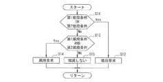
図2は、台数制御部22による冷凍機2の台数制御の処理手順を示す。Each
The
FIG. 2 shows a processing procedure of the number control of the
(ステップS11)
ステップS11では、台数制御部22は、第1増段条件又は第2増段条件を満たすか否かを判定する。
ここで、第1増段条件とは、冷凍機2の定格熱量に基づいて設定された冷凍機2を増段するための条件である。具体的には、第1増段条件とは、負荷側合計熱量がしきい値となる増段熱量を超えているときに満たしていると判定される条件である。ここで、負荷側合計熱量とは、二次側熱量、すなわち、各空調機9について供給する往水とその還水との温度差に対して流量を乗算して熱量(負荷熱量)を算出し、それら各空調機9について得た熱量を合計した値である。増段熱量は、現在運転している冷凍機それぞれに設定されている冷凍機定格冷凍能力(定格熱量)の総和である。
すなわち、第1増段条件は、
負荷側合計熱量>現在運転している冷凍機それぞれに設定されている冷凍機定格冷凍能力の総和 ・・・(1)
となる。(Step S11)
In step S11, the
Here, the first stage increase condition is a condition for increasing the stage of the
That is, the first stage increase condition is
Load-side total heat quantity> Sum of chiller rated refrigeration capacity set for each chiller currently operating (1)
It becomes.
また、第2増段条件とは、冷凍機2の冷水最大流量(冷凍機冷水最大流量)を基に冷凍機2を増段するための条件である。具体的には、第2増段条件とは、負荷側合計流量がしきい値となる増段流量を超えているときに満たしていると判定される条件である。ここで、冷凍機2の冷水最大流量とは、冷凍機2で処理可能な冷水の最大流量である。例えば、冷凍機2からみて余裕をもって選定している一次冷水ポンプ3の定格流量を基に決定される。負荷側合計流量とは、二次側流量、すなわち、各空調機9からの冷水の流量を合計した値である。増段流量は、現在運転している冷凍機それぞれに設定されている冷凍機の冷水最大流量の総和である。 The second stage increase condition is a condition for increasing the stage of the
すなわち、第2増段条件は、
負荷側合計流量>現在運転している冷凍機それぞれに設定されている冷凍機冷水最大流量の総和 ・・・(2)
となる。
このステップS11では、台数制御部22は、第1増段条件又は第2増段条件の少なくとも何れかを満たした場合、ステップS12に進む。台数制御部22は、そうでない場合、すなわち、第1増段条件及び第2増段条件の何れも満たさない場合、ステップS13に進む。That is, the second stage increase condition is
Load-side total flow rate> Sum of maximum chiller chilled water flow rate set for each chiller currently operating (2)
It becomes.
In step S11, when the
(ステップS12)
ステップS12では、台数制御部22は、増段要求をする。具体的には、台数制御部22は、予め決めてある冷凍機2の運転を開始させる。さらに、台数制御部22は、その冷凍機2の補機となる一次冷水ポンプ3の運転も同時に開始させる。そして、台数制御部22は、該図2に示す処理を終了する(前記ステップS11からの処理を再び開始する)。(Step S12)
In step S <b> 12, the
(ステップS13)
ステップS13では、台数制御部22は、第1減段条件及び第2減段条件を満たすか否かを判定する。
ここで、第1減段条件とは、冷凍機2の定格熱量を基に冷凍機2を減段するための条件である。具体的には、第1減段条件とは、負荷側合計熱量がしきい値となる減段熱量以下であるときに満たされていると判定される条件である。ここで、減段熱量とは、現在運転している冷凍機それぞれに設定されている冷凍機定格冷凍能力の総和から、現在運転している冷凍機のうち減段要求があったならば次に減段すると決めてある冷凍機の冷凍機定格冷凍能力及び冷凍機減段用ディファレンシャル熱量を減算した値である。冷凍機減段用ディファレンシャル熱量を用いることで、第1減段条件は、第1増段条件に対してヒステリシスを有するものとなる。(Step S13)
In step S13, the
Here, the first stage reduction condition is a condition for reducing the stage of the
すなわち、第1減段条件は、
負荷側合計熱量≦(現在運転している冷凍機それぞれに設定されている冷凍機定格冷凍能力の総和)−(現在運転している冷凍機のうち、減段要求があったならば次に減段すると決めてある冷凍機の冷凍機定格冷凍能力)−(冷凍機減段用ディファレンシャル熱量) ・・・(3)
となる。That is, the first stage reduction condition is
Load-side total heat quantity ≤ (total sum of chiller rated refrigeration capacities set for each of the currently operating refrigerators)-(of the currently operating refrigerators, if there is a step reduction request, then decrease Refrigerator rated refrigeration capacity of the chiller that is determined to be stepped)-(Differential heat amount for chiller step-down) (3)
It becomes.
また、第2減段条件とは、冷凍機2の冷水最大流量に基づいて設定された冷凍機2を減段するための条件である。具体的には、第2減段条件とは、負荷側合計流量がしきい値となる減段流量以下であるときに満たされていると判定される条件である。ここで、減段流量とは、現在運転している冷凍機それぞれに設定されている冷凍機冷水最大流量の総和から、現在運転している冷凍機のうち減段要求があったならば次に減段すると決めてある冷凍機の冷凍機冷水最大流量、及び冷凍機減段用ディファレンシャル流量を減算した値である。冷凍機減段用ディファレンシャル流量を用いることで、第2減段条件は、第2増段条件に対してヒステリシスを有するものとなる。 Further, the second stage reduction condition is a condition for reducing the stage of the
すなわち、第2減段条件は、
負荷側合計流量≦(現在運転している冷凍機それぞれに設定されている冷凍機冷水最大流量の総和)−(現在運転している冷凍機のうち、減段要求があったならば次に減段すると決めてある冷凍機の冷凍機冷水最大流量)−(冷凍機減段用ディファレンシャル流量) ・・・(4)
となる。
このステップS13では、台数制御部22は、第1減段条件及び第2減段条件の両方を満たした場合、ステップS14に進む。台数制御部22は、そうでない場合、すなわち、第1減段条件及び第2減段条件の一方でも満たさない場合、ステップS15に進む。That is, the second stage reduction condition is
Load-side total flow rate ≤ (total sum of chiller chilled water maximum flow rates set for each of the currently operating refrigerators)-(of the currently operating refrigerators, if there is a step reduction request, then decrease (Maximum flow rate of chiller chilled water that is determined to be stepped)-(Differential flow rate for chiller step-down) (4)
It becomes.
In step S13, the
(ステップS14)
ステップS14では、台数制御部22は、減段要求をする。具体的には、台数制御部22は、予め決めてある冷凍機2の運転を停止させる。さらに、台数制御部22は、その冷凍機2の補機となる一次冷水ポンプ3の運転も同時に停止させる。そして、台数制御部22は、該図2に示す処理を終了する(前記ステップS11からの処理を再び開始する)。(Step S14)
In step S <b> 14, the
(ステップS15)
ステップS15では、台数制御部22は、増減段要求をしない。すなわち、冷凍機2の現状の運転台数を維持する。そして、台数制御部22は、該図2に示す処理を終了する(前記ステップS11からの処理を再び開始する)。
なお、この第1の実施形態では、第1増段条件が対熱量増段条件に対応し、第2増段条件が対流量増段条件に対応し、第1減段条件が対熱量減段条件に対応し、第2減段条件が対流量減段条件に対応する。(Step S15)
In step S15, the
In the first embodiment, the first stage increase condition corresponds to the heat quantity increase condition, the second stage increase condition corresponds to the flow rate increase condition, and the first stage decrease condition corresponds to the heat quantity decrease stage. Corresponding to the conditions, the second stage reduction condition corresponds to the flow reduction stage condition.
(動作、作用及び効果)
空調システム1では、第1増段条件(前記(1)式)又は第2増段条件(前記(2)式)の少なくとも何れかを満たすと、増段要求により、予め決めてある冷凍機2と共にその補機となる一次冷水ポンプ3の運転を開始させる(前記ステップS11→ステップS12)。
一方、空調システム1では、第1減段条件(前記(3)式)及び第2減段条件(前記(4)式)の両方を満たすと、減段要求により、予め決めてある冷凍機2と共にその補機となる一次冷水ポンプ3の運転を停止させる(前記ステップS13→ステップS14)。(Operation, action and effect)
In the air conditioning system 1, when at least one of the first stage increase condition (formula (1)) or the second stage increase condition (formula (2)) is satisfied, the
On the other hand, in the air conditioning system 1, if both the first stage reduction condition (formula (3)) and the second stage reduction condition (formula (4)) are satisfied, the
また、空調システム1では、前記ステップS11の判定、及び前記ステップS13の判定の何れでも判定条件を満たす結果が得られない場合、増減段しない、すなわち、現状の運転台数を維持する(前記ステップS11→ステップS13→ステップS15)。
このように、第1増段条件(前記(1)式)又は第2増段条件(前記(2)式)の少なくとも何れかを満たす場合に、増段し、第1減段条件(前記(3)式)及び第2減段条件(前記(4)式)の両条件を満たす場合に、減段することで、二次側熱量が一次側熱量(冷却能力)を超えることもなく、かつ二次側流量が一次側流量を超えることもなく、冷凍機2の台数制御ができるようになる。これにより、二次側設備から戻ってくる冷水を的確に一次側で冷却できる。
また、第1増段条件と第1減段条件との間、及び第2増段条件と第2減段条件との間それぞれに、ヒステリシスを設けることで、冷凍機2の台数制御のハンチング等を防止できる。Further, in the air conditioning system 1, if neither of the determination in step S11 and the determination in step S13 yields a condition that satisfies the determination condition, the air conditioning system 1 does not increase or decrease, that is, maintains the current number of operating units (step S11). → Step S13 → Step S15).
As described above, when at least one of the first stage increase condition (formula (1)) or the second stage increase condition (formula (2)) is satisfied, the stage is increased and the first stage decrease condition (the ( 3))) and the second stage reduction condition (formula (4)) are satisfied, the secondary side heat quantity does not exceed the primary side heat quantity (cooling capacity) by reducing the stage, and The number of
In addition, by providing hysteresis between the first stage increasing condition and the first stage reducing condition and between the second stage increasing condition and the second stage reducing condition, hunting for controlling the number of the
(第2の実施形態)
(構成)
第2の実施形態の空調システムの基本的構成は、前記図1に示した第1の実施形態の空調システムの構成と同一である。
図3は、台数制御部22による冷凍機2の台数制御の処理手順を示す。(Second Embodiment)
(Constitution)
The basic configuration of the air conditioning system of the second embodiment is the same as the configuration of the air conditioning system of the first embodiment shown in FIG.
FIG. 3 shows a processing procedure of the number control of the
(ステップS21)
ステップS21では、台数制御部22は、第1増段条件、第2増段条件又は第3増段条件の何れかを満たすか否かを判定する。
ここで、第1増段条件及び第2増段条件は、前記第1の実施形態で説明した通りである。第3増段条件とは、冷凍機2の定格熱量に基づいて設定された冷凍機2を増段するための条件である。具体的には、第3増段条件とは、負荷側合計熱量がしきい値となる増段熱量を超えているときに満たしていると判定される条件である。ここで、負荷側合計熱量は、前記第1の実施形態で説明した通りである。また、ここでいう増段熱量は、現在運転している冷凍機それぞれに設定されている冷凍機定格冷凍能力の総和に、増段要求があったならば次に増段すると決めてある冷凍機の冷凍機定格冷凍能力を加算し、その加算値に冷凍機最適増段負荷率を乗算した値である。(Step S21)
In step S21, the
Here, the first stage increasing condition and the second stage increasing condition are as described in the first embodiment. The third stage increase condition is a condition for increasing the stage of the
ここで、図4は、インバータ冷凍機固有の特性図の一例であり、インバータ冷凍機である冷凍機2の冷却負荷率と本体(単体)COP(Coefficient Of Performance、成績係数)との関係を示す。この図4は、冷凍機2の冷却水出口温度(具体的には、冷水出口温度(7℃)との差分)をパラメータとして、冷却負荷率と本体COPとの関係を示す。
図4に示すように、冷凍機2の冷却水出口温度が低いほど(もしくは温度偏差が小さいほど)、本体COP全体が大きくなる。そして、冷凍機2の冷却水出口温度が低くなると(もしくは温度偏差が小さくなると)、冷却負荷率が100(%)未満で本体COPの最大点(最大COP)が得られるようになる。さらに、冷凍機2の温度偏差が小さくなるほど、その本体COPの最大点は、冷却負荷率がより低くなる方向に移動するようになる。すなわち、冷凍機2の温度偏差が小さくなるほど、高効率で冷凍機2を運転させることができるようになる。例えば、圧縮機の回転数を抑えて、冷凍機2を運転させることができるようになる。Here, FIG. 4 is an example of a characteristic diagram unique to the inverter refrigerator, and shows a relationship between the cooling load factor of the
As shown in FIG. 4, the lower the cooling water outlet temperature of the refrigerator 2 (or the smaller the temperature deviation), the larger the main body COP. When the cooling water outlet temperature of the
図5は、前記図4と対比するために示す固定速ターボ冷凍機(定速機)固有の特性図の一例であり、固定速ターボ冷凍機の冷却負荷率と本体COPとの関係を示す。
図5に示すように、インバータ冷凍機同様に、固定速ターボ冷凍機の温度偏差が小さいほど、本体COP全体が大きくなる。しかし、インバータ冷凍機(前記図4の特性)と比較して、温度偏差の減少に対する本体COP全体の増加割合は小さい。さらに、固定速ターボ冷凍機の温度偏差が小さくなっても、インバータ冷凍機で得られたような本体COPの最大点(前記図4の特性)が顕著に現れない。すなわち、固定速ターボ冷凍機では、温度偏差が小さくなっても、インバータ冷凍機の場合のように、低い負荷率の場合には高効率で運転できるわけでもない。FIG. 5 is an example of a characteristic diagram specific to the fixed-speed turbo chiller (constant-speed machine) shown for comparison with FIG. 4, and shows the relationship between the cooling load factor of the fixed-speed turbo chiller and the main body COP.
As shown in FIG. 5, like the inverter refrigerator, the entire body COP becomes larger as the temperature deviation of the fixed speed turbo refrigerator is smaller. However, compared with the inverter refrigerator (characteristic of FIG. 4), the increase rate of the entire main body COP with respect to the decrease in temperature deviation is small. Furthermore, even if the temperature deviation of the fixed speed centrifugal chiller becomes small, the maximum point (characteristic of FIG. 4) of the main body COP as obtained by the inverter chiller does not appear remarkably. That is, in the fixed speed turbo chiller, even if the temperature deviation becomes small, it cannot be operated with high efficiency in the case of a low load factor as in the case of the inverter chiller.
本実施形態において、冷凍機最適増段負荷率とは、前記図4に示す本体COPの最大値(図4中の黒丸印)が得られるときの冷却負荷率のことである。そして、前記図4に示したように、本体COPの最大値が冷凍機2の温度偏差に応じて変化する特性があることから、この特性を予め実験等により求めておく。
図6は、温度偏差から冷凍機最適増段負荷率を得るためのマップの一例を示す。図6は、温度偏差と、冷凍機最適増段負荷率との関係を示す。図6に示すように、温度偏差が小さくなるほど、冷凍機最適増段負荷率が小さくなる(本例では、0.3〜1.0の間で変化)。In this embodiment, the refrigerator optimum stage load factor is the cooling load factor when the maximum value of the main body COP shown in FIG. 4 (black circle in FIG. 4) is obtained. As shown in FIG. 4, since the maximum value of the main body COP has a characteristic that changes according to the temperature deviation of the
FIG. 6 shows an example of a map for obtaining the refrigerator maximum stage load factor from the temperature deviation. FIG. 6 shows the relationship between the temperature deviation and the refrigerator maximum stage load factor. As shown in FIG. 6, as the temperature deviation becomes smaller, the refrigerator optimum stage increasing load factor becomes smaller (changed between 0.3 and 1.0 in this example).
例えば、実験値、経験値又は理論値として、温度偏差と冷凍機最適増段負荷率との関係からなるマップを得る。例えば、複数の温度偏差について冷凍機最適増段負荷率を得る実験を行い、その実験結果よりマップを得る。このとき、実験を行わない温度偏差に対応する冷凍機最適増段負荷率については、他のデータを補間して得るようにする。
また、下記(5)式のように、冷凍機最適増段負荷率f1(x)を得ることもできる。
f1(x)=a・x3+b・x2+c・x+d ・・・(5)
ここで、xは温度偏差である。a,b,c,dは定数である。For example, as an experimental value, an empirical value, or a theoretical value, a map including the relationship between the temperature deviation and the refrigerator optimum stage load factor is obtained. For example, an experiment for obtaining an optimum stage load factor for the refrigerator for a plurality of temperature deviations is performed, and a map is obtained from the experimental results. At this time, the refrigerator optimum stage load factor corresponding to the temperature deviation for which no experiment is performed is obtained by interpolating other data.
Further, as shown in the following equation (5), the refrigerator optimum stage load factor f1 (x) can be obtained.
f1 (x) = a · x3 + b · x2 + c · x + d (5)
Here, x is a temperature deviation. a, b, c, and d are constants.
以上のような冷凍機最適増段負荷率の取得については、具体的には、台数制御部22は、冷却水出口温度センサ35と冷水出口温度センサ31から得た、温度偏差を算出し、算出した温度偏差に対応する冷凍機最適増段負荷率を算出した温度偏差に対応する冷凍機最適増段負荷率を、前記マップや数式により算出している。
ここで、冷却水出口温度や冷水出口温度は、センサで計測された値を用いる代わりに冷凍機2を最適運転させるために演算した仮想的な温度として温度偏差を求め、冷凍機最適増段負荷率を算出することもできる。Regarding the acquisition of the refrigerator optimum stage load factor as described above, specifically, the
Here, the cooling water outlet temperature and the cooling water outlet temperature are obtained as a virtual temperature calculated for optimal operation of the
また、冷凍機最適増段負荷率を算出するための本体COPは、冷凍機本体だけでなく、冷水ポンプ、冷却水ポンプ、冷却塔ファンまで含めた、冷凍機系統の総合COPとすることもできる。総合COPの算出にあたっては、外気条件と冷却負荷をもとに運転シミュレーションを作成し、その結果をもとに、図6のかわりに外気湿球温度と冷凍機最適増段負荷率の関係式を作成してもよい。この場合は(5)式のxは外気湿球温度となる。 Moreover, the main body COP for calculating the optimum stage load factor for the refrigerator can be not only the refrigerator body but also the total COP of the refrigerator system including the cold water pump, the cooling water pump, and the cooling tower fan. . In calculating the total COP, an operation simulation is created based on the outside air conditions and the cooling load. Based on the result, a relational expression between the outside air wet bulb temperature and the optimum stage load factor of the refrigerator is obtained instead of FIG. You may create it. In this case, x in the equation (5) is the outside wet bulb temperature.
このようして得られる冷凍機最適増段負荷率を用いて、第3増段条件は、
負荷側合計熱量>((現在運転している冷凍機それぞれに設定されている冷凍機定格冷凍能力の総和)+(増段要求があったならば次に増段すると決めてある冷凍機の冷凍機定格冷凍能力))×(冷凍機最適増段負荷率) ・・・(6)
となる。
このステップS21では、台数制御部22は、第1増段条件、第2増段条件又は第3増段条件の少なくとも何れかを満たした場合、ステップS22に進む。台数制御部22は、そうでない場合、すなわち、第1増段条件、第2増段条件及び第3増段条件の何れも満たさない場合、ステップS23に進む。Using the refrigerator optimum stage load factor obtained in this way, the third stage stage condition is
Load side total heat quantity> ((total sum of chiller rated refrigeration capacities set for each chiller currently in operation) + (freezer refrigeration that has been decided to increase next if requested) (Refrigerating machine rated refrigeration capacity)) x (Refrigerating machine optimum stage load factor) (6)
It becomes.
In this step S21, the
(ステップS22)
ステップS22では、台数制御部22は、増段要求をする。具体的には、台数制御部22は、予め決めてある冷凍機2の運転を開始させる。さらに、台数制御部22は、その冷凍機2の補機となる一次冷水ポンプ3の運転も同時に開始させる。そして、台数制御部22は、該図3に示す処理を終了する(前記ステップS21からの処理を再び開始する)。(Step S22)
In step S22, the
(ステップS23)
ステップS23では、台数制御部22は、第1減段条件、第2減段条件及び第3減段条件を満たすか否かを判定する。
ここで、第1減段条件及び第2減段条件は、前記第1の実施形態で説明した通りである。第3減段条件とは、冷凍機2の定格熱量に基づいて設定された冷凍機2を減段するための条件である。具体的には、第3減段条件とは、負荷側合計熱量がしきい値となる減段熱量以下であるときに満たされていると判定される条件である。ここで、負荷側合計熱量は、前記第1の実施形態で説明した通りである。また、ここでいう減段熱量とは、現在運転している冷凍機それぞれに設定されている冷凍機定格冷凍能力の総和に冷凍機最適減段負荷率を乗算し、その乗算値から冷凍機減段用ディファレンシャル熱量を減算した値である。ここで、冷凍機最適減段負荷率は、前記冷凍機最適増段負荷率(冷凍機最適負荷率)と同等な値である(冷凍機最適負荷率=冷凍機最適増段負荷率=冷凍機最適減段負荷率)。また、冷凍機減段用ディファレンシャル熱量を用いることで、第3減段条件は、第3増段条件に対してヒステリシスを有するものとなる。(Step S23)
In step S23, the
Here, the first step reduction condition and the second step reduction condition are as described in the first embodiment. The third stage reduction condition is a condition for reducing the stage of the
すなわち、第3減段条件は、
負荷側合計熱量≦(現在運転している冷凍機それぞれに設定されている冷凍機定格冷凍能力の総和)×(冷凍機最適減段負荷率)−(冷凍機減段用ディファレンシャル熱量) ・・・(7)
となる。
このステップS23では、台数制御部22は、第1減段条件、第2減段条件及び第3減段条件の全てを満たした場合、ステップS24に進む。台数制御部22は、そうでない場合、すなわち、第1減段条件、第2減段条件及び第3減段条件の何れかを満たさない場合、ステップS25に進む。That is, the third stage reduction condition is
Load-side total heat quantity ≤ (total sum of refrigeration machine rated refrigeration capacities set for each of the currently operating refrigerators) x (refrigerator optimum step load reduction factor)-(differential heat amount for refrigerator step reduction) ... (7)
It becomes.
In step S23, the
(ステップS24)
ステップS24では、台数制御部22は、減段要求をする。具体的には、台数制御部22は、予め決めてある冷凍機2の運転を停止させる。さらに、台数制御部22は、その冷凍機2の補機となる一次冷水ポンプ3の運転も同時に停止させる。そして、台数制御部22は、該図3に示す処理を終了する(前記ステップS21からの処理を再び開始する)。(Step S24)
In step S24, the
(ステップS25)
ステップS25では、台数制御部22は、増減段要求をしない。そして、台数制御部22は、該図3に示す処理を終了する(前記ステップS21からの処理を再び開始する)。
なお、この第2の実施形態では、第1増段条件及び第3増段条件が複数の対熱量増段条件に対応し、第2増段条件が対流量増段条件に対応し、第1減段条件及び第3減段条件が複数の対熱量減段条件に対応し、第2減段条件が対流量減段条件に対応する。(Step S25)
In step S25, the
In the second embodiment, the first stage increase condition and the third stage increase condition correspond to a plurality of heat increase stage conditions, the second stage increase condition corresponds to the flow rate increase condition, The stage reduction condition and the third stage reduction condition correspond to a plurality of heat reduction stage conditions, and the second stage reduction condition corresponds to the flow rate reduction stage condition.
(動作、作用及び効果)
空調システム1では、第1増段条件(前記(1)式)、第2増段条件(前記(2)式)又は第3増段条件(前記(6)式)の少なくとも何れかを満たすと、増段要求により、予め決めてある冷凍機2と共にその補機となる一次冷水ポンプ3の運転を開始させる(前記ステップS21→ステップS22)。(Operation, action and effect)
In the air conditioning system 1, when at least one of the first stage increase condition (the expression (1)), the second stage increase condition (the formula (2)), or the third stage increase condition (the formula (6)) is satisfied. Then, in response to the stage increase request, the operation of the primary
一方、空調システム1では、第1減段条件(前記(3)式)、第2減段条件(前記(4)式)、及び第3減段条件(前記(7)式)の全てを満たすと、減段要求により、予め決めてある冷凍機2と共にその補機となる一次冷水ポンプ3の運転を停止させる(前記ステップS23→ステップS24)。
また、空調システム1では、前記ステップS21の判定、及び前記ステップS23の判定の何れでも判定条件を満たす結果が得られない場合、増減段しない、すなわち、現状の運転台数を維持する(前記ステップS21→ステップS23→ステップS25)。On the other hand, in the air conditioning system 1, all of the first step reduction condition (formula (3)), the second step reduction condition (formula (4)), and the third step reduction condition (formula (7)) are satisfied. Then, in response to the stage reduction request, the operation of the primary
Further, in the air conditioning system 1, if neither of the determination in step S21 and the determination in step S23 obtains a result that satisfies the determination condition, the air conditioning system 1 does not increase / decrease, that is, maintains the current operating number (step S21). → Step S23 → Step S25).
このように、第1増段条件(前記(1)式)、第2増段条件(前記(2)式)、又は第3増段条件(前記(6)式)の少なくとも何れかを満たす場合に、増段し、第1減段条件(前記(3)式)、第2減段条件(前記(4)式)、及び第3減段条件(前記(7)式)の全条件を満たす場合に、減段することで、前記第1の実施形態と同様に、二次側熱量が一次側熱量(冷却能力)を超えることもなく、かつ二次側流量が一次側流量を超えることもなく、冷凍機2の台数制御ができるようになる。これにより、二次側設備から戻ってくる冷水を的確に一次側で冷却できる。 As described above, when at least one of the first stage increase condition (the expression (1)), the second stage increase condition (the formula (2)), or the third stage increase condition (the formula (6)) is satisfied. In addition, the first stage reduction condition (formula (3)), the second stage reduction condition (formula (4)), and the third stage reduction condition (formula (7)) are all satisfied. In this case, by reducing the stage, the secondary heat quantity does not exceed the primary heat quantity (cooling capacity) and the secondary flow rate may exceed the primary flow rate, as in the first embodiment. The number of
また、第1増段条件と第1減段条件との間、第2増段条件と第2減段条件との間、及び第3増段条件と第3減段条件との間それぞれに、ヒステリシスを設けることで、前記第1の実施形態と同様に、冷凍機2の台数制御のハンチング等を防止できる。
さらに、第2の実施形態では、第3増段条件により冷凍機2が増段された場合、そのときの(複数台の)冷凍機2は、本体COPの最大値を得る冷却負荷率で運転されるようになる。In addition, between the first step increase condition and the first step decrease condition, between the second step increase condition and the second step decrease condition, and between the third step increase condition and the third step decrease condition, respectively. By providing the hysteresis, it is possible to prevent hunting or the like of the number control of the
Furthermore, in the second embodiment, when the
例えば、現在の温度偏差に対応して冷凍機最適増段負荷率が0.3であるときに、第3増段条件により冷凍機2が増段されると、各冷凍機2は、30%相当の冷却負荷率にあり、かつ本体COPが最大点となっている動作点で、運転されるようになる。
より具体的な例を示すと、45%相当の冷却負荷率で2台の冷凍機2を運転しているときに、第3増段条件を満たした場合、1台増段されて、3台の冷凍機2が稼動するようになる。このとき、冷凍機最適増段負荷率が0.3であった場合、3台の冷凍機2は、30%相当の冷却負荷率にあり、かつ本体COPが最大点となっている動作点で、運転されるようになる。すなわち、運転を継続する2台の冷凍機2に加えて、新たに運転を開始した冷凍機2が、本体COPが最大点となっている動作点で運転されるようになる。For example, when the refrigerator maximum stage load factor corresponding to the current temperature deviation is 0.3, when the
More specifically, when two
これにより、運転される冷凍機2それぞれの冷却負荷率が45%相当から30%相当に低下するため、一次側全体では、冷凍機2を増段してもなお、高効率で冷水を冷却できるようになる。
例えば、前記第1の実施形態では、現在運転している冷凍機の運転状態が定格熱量や冷水最大流量になったときに、冷凍機を増段している。これに対して、第2の実施形態では、現在運転している冷凍機の運転状態が定格熱量や定格熱量に達してなく、運転状態に余裕があるときでも、増段するようになる。しかし、第2の実施形態では、本体COPが最大点となっている動作点で、各冷凍機2を運転することができる。
これにより、前記第1の実施形態との比較では、冷凍機2が増段され易くなるものの(運転台数が増えるものの)、一次側全体として、高効率で冷水を冷却できるようになる。As a result, the cooling load factor of each of the operated
For example, in the first embodiment, when the operating state of the currently operated refrigerator reaches the rated heat amount or the maximum cold water flow rate, the number of refrigerators is increased. On the other hand, in 2nd Embodiment, even if the driving | running state of the refrigerator which is drive | operating does not reach the rated heat amount or the rated heat amount and there is a margin in the operating state, the number of stages increases. However, in the second embodiment, each
Thereby, compared with the said 1st Embodiment, although it becomes easy to increase the stage of the refrigerator 2 (though the number of operation increases), as a whole primary side, it becomes possible to cool cold water with high efficiency.
(第3の実施形態)
(構成)
第3の実施形態の空調システムの基本的構成は、前記図1に示した第1の実施形態の空調システムの構成と同一である。
図7は、台数制御部22による冷凍機2の台数制御の処理手順を示す。(Third embodiment)
(Constitution)
The basic configuration of the air conditioning system of the third embodiment is the same as the configuration of the air conditioning system of the first embodiment shown in FIG.
FIG. 7 shows a processing procedure for controlling the number of
(ステップS31)
ステップS31では、台数制御部22は、第2増段条件、第3増段条件又は第4増段条件の何れかを満たすか否かを判定する。
ここで、第2増段条件及び第3増段条件は、前記第1及び第2の実施形態で説明した通りである。第4増段条件とは、冷凍機2の定格熱量に基づいて設定された冷凍機2を増段するための条件である。具体的には、第4増段条件とは、負荷側合計熱量がしきい値となる増段熱量を超えているときに満たしていると判定される条件である。ここで、負荷側合計熱量は、前記第1の実施形態で説明した通りである。また、ここでいう増段熱量は、現在運転している冷凍機それぞれに設定されている冷凍機定格冷凍能力の総和に冷凍機冷凍余裕率の現在値を乗算した値である。(Step S31)
In step S31, the
Here, the second stage increase condition and the third stage increase condition are as described in the first and second embodiments. The fourth stage increase condition is a condition for increasing the stage of the
ここで、冷凍機冷凍余裕率を説明する。
前記図4を用いて説明したように、温度偏差がその定格値(本例では、37℃(冷却水出口温度)−7℃(冷水出口温度)=30℃)から低下すると、高効率で冷水を冷却できるようになる。言い換えれば、このことは、冷凍機2の消費電力(消費電流)を抑えて冷水を冷却できるということである。すなわち、冷凍機2の定格能力以上の冷水負荷を生産しても、冷凍機2の上限電力(上限電流)に上昇させることなく、消費電力に余裕をもって冷凍機2の運転継続が可能になることである。Here, the refrigerator freezing margin will be described.
As described with reference to FIG. 4, when the temperature deviation falls from its rated value (in this example, 37 ° C. (cooling water outlet temperature) −7 ° C. (cold water outlet temperature) = 30 ° C.) Can be cooled. In other words, this means that the cold water can be cooled while suppressing the power consumption (current consumption) of the
図8は、このような関係を、冷水生産能力と本体消費電力(本体消費電流)との関係として表した例である。ここで、冷水生産能力は、冷凍機2の冷水の生産能力である。また、本体消費電力は、冷凍機2の消費電力である。冷水生産能力と本体消費電力との関係は、温度偏差が定格温度である30℃のときに、冷水生産能力が100%となり、本体消費電力が100%(本体消費電力の上限電力)となる。 FIG. 8 is an example showing such a relationship as the relationship between the cold water production capacity and the power consumption of the main body (main body current consumption). Here, the cold water production capacity is the cold water production capacity of the
この例では、温度偏差が8℃程度まで低下すると、冷却負荷率の低下に起因して、冷水生産能力が120%まで上昇してようやく本体消費電力の上限電力(100%)になる。すなわち、温度偏差が8℃程度まで低下すると、冷凍機2は最大120%の冷水生産能力で運転させることが可能になる。
冷凍機冷凍余裕率を、温度偏差(冷却水出口温度−冷水出口温度)を用いて、
冷凍機冷凍余裕率=f2(冷却水出口温度−冷水出口温度) ・・・(8)
と定義する。In this example, when the temperature deviation decreases to about 8 ° C., the cold water production capacity rises to 120% due to the decrease in the cooling load factor, and finally reaches the upper limit power (100%) of the main body power consumption. That is, when the temperature deviation decreases to about 8 ° C., the
Using the temperature deviation (cooling water outlet temperature-cold water outlet temperature),
Refrigerator freezing margin rate = f2 (cooling water outlet temperature−cold water outlet temperature) (8)
It is defined as
この(8)式に示すように、温度偏差から冷凍機冷凍余裕率を定義する。この冷凍機冷凍余裕率は、冷凍機2の定格熱量に対する該冷凍機2の現在の運転状態の余裕の度合いを示す値となる。より具体的には、冷凍機冷凍余裕率は、冷凍機2の本体消費電力の上限電力となる動作点に対する冷凍機2の運転状態(現在の本体消費電力)の余裕の度合いを示す値となる。この冷凍機冷凍余裕率は、1.0〜1.5の間で変化する。例えば、冷凍機冷凍余裕率が1.0の場合とは、冷凍機2の本体消費電力が上限電力(100%)に達している場合を言う。 As shown in the equation (8), the freezer freezing margin is defined from the temperature deviation. The freezer freezing margin rate is a value indicating the degree of margin of the current operating state of the
図9は、前記(8)式により得られる、温度偏差と冷凍機冷凍余裕率との関係の一例を示す。図9に示すように、温度偏差が小さくなると、冷凍機冷凍余裕率が1.0から1.5に増加していく。これは、温度偏差が小さいほど、冷凍機2の本体消費電力に余裕があり、冷凍機2の冷水生産能力に余裕があることを示す。
このような冷凍機最適増段負荷率の取得については、具体的には台数制御部22は冷却水出口温度センサ35と冷水出口温度センサ31から得た、温度偏差に対応する冷凍機冷凍余裕率を算出する。FIG. 9 shows an example of the relationship between the temperature deviation and the freezer freezing margin rate obtained by the equation (8). As shown in FIG. 9, as the temperature deviation becomes smaller, the freezer freezing margin increases from 1.0 to 1.5. This indicates that the smaller the temperature deviation, the more the power consumption of the main body of the
Regarding acquisition of the refrigerator optimum stage load factor, specifically, the
ここで、冷却水出口温度や冷水出口温度は、センサで計測された値を用いる代わりに冷凍機2を最適運転させるために演算した仮想的な温度として温度偏差を求め、冷凍機最適増段負荷率を算出することもできる。
このようにして得られる冷凍機冷凍余裕率を用いて、第4増段条件は、
負荷側合計熱量>(現在運転している冷凍機それぞれに設定されている冷凍機定格冷凍能力の総和)×(冷凍機冷凍余裕率の現在値) ・・・(9)
となる。Here, the cooling water outlet temperature and the cooling water outlet temperature are obtained as a virtual temperature calculated for optimal operation of the
Using the refrigerator freezing margin obtained in this way, the fourth stage increase condition is
Load-side total heat quantity> (total sum of chiller rated refrigeration capacities set for each chiller currently in operation) × (current value of freezer refrigeration margin) (9)
It becomes.
この第4増段条件は、前記第1の実施形態の第1増段条件(前記(1)式)を変形した条件である。
このステップS31では、台数制御部22は、第2増段条件、第3増段条件又は第4増段条件の少なくとも何れかを満たした場合、ステップS32に進む。台数制御部22は、そうでない場合、すなわち、第2増段条件、第3増段条件及び第4増段条件の何れも満たさない場合、ステップS33に進む。The fourth stage increase condition is a condition obtained by modifying the first stage increase condition (the formula (1)) of the first embodiment.
In step S31, if the
(ステップS32)
ステップS32では、台数制御部22は、増段要求をする。具体的には、台数制御部22は、予め決めてある冷凍機2の運転を開始させる。さらに、台数制御部22は、その冷凍機2の補機となる一次冷水ポンプ3の運転も同時に開始させる。そして、台数制御部22は、該図7に示す処理を終了する(前記ステップS31からの処理を再び開始する)。(Step S32)
In step S <b> 32, the
(ステップS33)
ステップS33では、台数制御部22は、第2減段条件、第3減段条件及び第4減段条件を満たすか否かを判定する。
ここで、第2減段条件及び第3減段条件は、前記第1及び第2の実施形態で説明した通りである。第4減段条件とは、冷凍機2の定格熱量に基づいて設定された冷凍機2を減段するための条件である。具体的には、第4減段条件とは、負荷側合計熱量がしきい値となる減段熱量以下であるときに満たされていると判定される条件である。ここで、負荷側合計熱量は、前記第1の実施形態で説明した通りである。(Step S33)
In step S <b> 33, the
Here, the second stage reduction condition and the third stage reduction condition are as described in the first and second embodiments. The fourth stage reduction condition is a condition for reducing the stage of the
また、ここでいう減段熱量は、次のように求められる。
先ず、現在運転している冷凍機2それぞれに設定されている冷凍機定格冷凍能力の総和から、現在運転している冷凍機のうち減段要求があったならば次に減段すると決めてある冷凍機の冷凍機定格冷凍能力を減算する。そして、その減算値に冷凍機冷凍余裕率の現在値を乗算する。さらに、その乗算値から冷凍機減段用ディファレンシャル熱量を減算する。冷凍機減段用ディファレンシャル熱量を用いることで、第4減段条件は、第4増段条件に対してヒステリシスを有するものとなる。Moreover, the amount of heat | fever reduction here is calculated | required as follows.
First, from the sum of the refrigerator rated refrigeration capacities set for each of the currently operated
以上より、第4減段条件は、
負荷側合計熱量≦((現在運転している冷凍機それぞれに設定されている冷凍機定格冷凍能力の総和)−(現在運転している冷凍機のうち、減段要求があったならば次に減段すると決めてある冷凍機の冷凍機定格冷凍能力))×(冷凍機冷凍余裕率の現在値)−(冷凍機減段用ディファレンシャル熱量) ・・・(10)
となる。From the above, the fourth stage reduction condition is
Load side total heat quantity ≤ ((total sum of chiller rated refrigeration capacities set for each chiller currently in operation)-(if there is a stage reduction request among the chillers currently in operation, Refrigerator rated refrigeration capacity of a refrigerator that has been decided to be stepped down)) x (current value of freezer freezing margin)-(differential calorific value for chiller step down) (10)
It becomes.
この第4減段条件は、前記第1の実施形態の第1減段条件(前記(3)式)を変形した条件である。
このステップS33では、台数制御部22は、第2減段条件、第3減段条件及び第4減段条件の全てを満たした場合、ステップS34に進む。台数制御部22は、そうでない場合、すなわち、第2減段条件、第3減段条件及び第4減段条件の何れかを満たさない場合、ステップS35に進む。The fourth step reduction condition is a condition obtained by modifying the first step reduction condition (formula (3)) of the first embodiment.
In step S33, the
(ステップS34)
ステップS34では、台数制御部22は、減段要求をする。具体的には、台数制御部22は、予め決めてある冷凍機2の運転を停止させる。さらに、台数制御部22は、その冷凍機2の補機となる一次冷水ポンプ3の運転も同時に停止させる。そして、台数制御部22は、該図7に示す処理を終了する(前記ステップS31からの処理を再び開始する)。(Step S34)
In step S <b> 34, the
(ステップS35)
ステップS35では、台数制御部22は、増減段要求をしない。そして、台数制御部22は、該図7に示す処理を終了する(前記ステップS31からの処理を再び開始する)。
なお、この第2の実施形態では、第3増段条件及び第4増段条件が複数の対熱量増段条件に対応し、第2増段条件が対流量増段条件に対応し、第3減段条件及び第4減段条件が複数の対熱量減段条件に対応し、第2減段条件が対流量減段条件に対応する。(Step S35)
In step S35, the
In the second embodiment, the third stage increasing condition and the fourth stage increasing condition correspond to a plurality of heat quantity increasing conditions, the second stage increasing condition corresponds to the counter flow rate increasing condition, The stage reduction condition and the fourth stage reduction condition correspond to a plurality of heat reduction stage conditions, and the second stage reduction condition corresponds to the counter flow reduction stage condition.
(動作、作用及び効果)
空調システム1では、第2増段条件(前記(2)式)、第3増段条件(前記(6)式)又は第4増段条件(前記(9)式)の少なくとも何れかを満たすと、増段要求により、予め決めてある冷凍機2と共にその補機となる一次冷水ポンプ3の運転を開始させる(前記ステップS31→ステップS32)。(Operation, action and effect)
In the air conditioning system 1, when at least one of the second stage increase condition (the expression (2)), the third stage increase condition (the formula (6)), or the fourth stage increase condition (the formula (9)) is satisfied. Then, in response to the stage increase request, the operation of the primary
一方、空調システム1では、第2減段条件(前記(4)式)、第3減段条件(前記(7)式)、及び第4減段条件(前記(10)式)の全てを満たすと、減段要求により、予め決めてある冷凍機2と共にその補機となる一次冷水ポンプ3の運転を停止させる(前記ステップS33→ステップS34)。
また、空調システム1では、前記ステップS31の判定、及び前記ステップS33の判定の何れでも判定条件を満たす結果が得られない場合、増減段しない、すなわち、現状の運転台数を維持する(前記ステップS31→ステップS33→ステップS35)。On the other hand, in the air conditioning system 1, all of the second step-reducing condition (formula (4)), the third step-reduction condition (formula (7)), and the fourth step-reduction condition (formula (10)) are satisfied. Then, in response to the stage reduction request, the operation of the primary
Further, in the air conditioning system 1, when neither of the determination in step S31 and the determination in step S33 yields a result that satisfies the determination condition, the air conditioning system 1 does not increase or decrease, that is, maintains the current number of operating units (step S31). → Step S33 → Step S35).
これにより、第2増段条件と第2減段条件との間、第3増段条件と第3減段条件との間、及び第4増段条件と第4減段条件との間それぞれに、ヒステリシスを設けることで、前記第1及び第2の実施形態と同様に、冷凍機2の台数制御のハンチング等を防止できる。
また、第3の実施形態では、第4増段条件により冷凍機2が増段された場合(増段直前では)、そのときの(複数台の)冷凍機2は、その冷凍機2の定格熱量付近で運転されている。この増段時に温度偏差が小さい(冷却水出口温度が低い)ようなときには、運転効率(本体COP、又はその本体COPの最大値)が上昇する特性に起因して、冷凍機2は、消費電力を上限電力以下として、冷凍機の定格熱量(定格能力)以上の冷水負荷を生産できる。Accordingly, between the second stage increasing condition and the second stage reducing condition, between the third stage increasing condition and the third stage reducing condition, and between the fourth stage increasing condition and the fourth stage reducing condition, respectively. By providing hysteresis, it is possible to prevent hunting or the like for controlling the number of
In the third embodiment, when the
より具体的な例を示すと、2台の冷凍機2を運転しているときに、第4増段条件を満たした場合、1台増段されて、3台の冷凍機2が稼動するようになる。このとき、前記(8)式より冷凍機冷凍余裕率の現在値が1.5として算出されている場合には、増段前の2台の冷凍機2が冷水生産能力を150%程度に発揮して運転されている。このとき、2台の冷凍機2の定格能力以上の冷水負荷を生産しても、上限電力以下の本体消費電力で冷凍機2が運転されている。 As a more specific example, when operating the two
そして、2台の冷凍機2がそのような150%程度の冷水生産能力を超えると、増段されて、3台の冷凍機2が稼動するようになる。
例えば、前記第1の実施形態では、現在運転している冷凍機の運転状態が定格熱量や冷水最大流量になったときに、冷凍機を増段している。これに対して、第3の実施形態では、現在運転している冷凍機の運転状態が定格熱量を超えても、本体消費電力を指標とした冷凍機の運転状態に余裕がある限り、増段せずに、運転台数を維持することが可能になる。
これにより、前記第1の実施形態との比較では、冷凍機2の冷水生産能力を最大限に発揮させて冷凍機の台数制御ができるようになる。When the two
For example, in the first embodiment, when the operating state of the currently operated refrigerator reaches the rated heat amount or the maximum cold water flow rate, the number of refrigerators is increased. On the other hand, in the third embodiment, even if the operating state of the currently operated refrigerator exceeds the rated heat amount, as long as there is a margin in the operating state of the refrigerator using the power consumption of the main body as an index, the stage is increased. It is possible to maintain the number of operating units without doing so.
Thereby, in comparison with the first embodiment, the number of refrigerators can be controlled by maximizing the cold water production capacity of the
本発明は、インバータ冷凍機を備えた空調システムに利用できる。 The present invention can be used for an air conditioning system including an inverter refrigerator.
1 空調システム、2 冷凍機、3 一次冷水ポンプ、9 空調機(熱負荷源) 制御装置、21 インバータ制御部、22 台数制御部、31 冷水出口温度センサ、33 冷却塔、35 冷却水出口温度センサ DESCRIPTION OF SYMBOLS 1 Air conditioning system, 2 Refrigerator, 3 Primary chilled water pump, 9 Air conditioner (heat load source) control device, 21 Inverter control part, 22 Number control part, 31 Cold water outlet temperature sensor, 33 Cooling tower, 35 Cooling water outlet temperature sensor
Claims (5)
Translated fromJapanese前記熱負荷源から前記冷凍機側に戻される冷水が有する熱量である負荷側合計熱量に基づいて設定される前記冷凍機の増段条件及び減段条件を、それぞれ対熱量増段条件及び対熱量減段条件とし、
前記熱負荷源から前記冷凍機側に戻される冷水の流量である負荷側合計流量に基づいて設定される前記冷凍機の増段条件及び減段条件を、それぞれ対流量増段条件及び対流量減段条件とし、
前記対熱量増段条件及び前記対流量増段条件の何れかを満たす場合、前記冷凍機を1台増段し、前記対熱量減段条件及び前記対流量減段条件の全条件を満たす場合、前記冷凍機を1台減段することを特徴とする冷凍機の台数制御方法。A plurality of refrigerators as primary equipment are arranged in parallel, a heat load source as a secondary equipment is connected to the plurality of refrigerators, the plurality of refrigerators and the heat load source, In the air conditioning system in which cold water can circulate between, the number control method of the number of refrigerators for controlling the number by increasing or decreasing the number of the plurality of refrigerators,
The stage-increase condition and stage-down condition of the refrigerator set based on the load-side total heat quantity, which is the quantity of heat that the cold water returned from the heat load source to the refrigerator side has, respectively, As step reduction condition,
The step-up condition and step-down condition of the refrigerator set based on the load-side total flow rate, which is the flow rate of cold water returned from the heat load source to the refrigerator side, respectively, The stage condition,
When satisfying either of the heat increase stage condition and the flow rate increase condition, if the refrigerator is increased by one unit, if all conditions of the heat reduction stage condition and the flow rate reduction condition are satisfied, A method of controlling the number of refrigerators, comprising reducing one of the refrigerators.
前記対流量減段条件は、前記対流量増段条件に対してヒステリシスを有することを特徴とする請求項1に記載の冷凍機の台数制御方法。The heat quantity reduction stage condition has hysteresis with respect to the heat quantity increase stage condition,
The method for controlling the number of refrigerators according to claim 1, wherein the anti-flow rate reduction condition has hysteresis with respect to the anti-flow rate increase condition.
前記対熱量増段条件としての第1増段条件を、
負荷側合計熱量>現在運転している冷凍機それぞれに設定されている定格熱量の総和
とし、
前記対流量増段条件としての第2増段条件を、
負荷側合計流量>現在運転している冷凍機それぞれに設定されている冷水最大流量の総和
とし、
前記対熱量減段条件としての第1減段条件を、
負荷側合計熱量≦(現在運転している冷凍機それぞれに設定されている定格熱量の総和)−(現在運転している冷凍機のうち、次に減段すると決めてある冷凍機の定格熱量)−(冷凍機減段用ディファレンシャル熱量)
とし、
前記対流量減段条件としての第2減段条件を、
負荷側合計流量≦(現在運転している冷凍機それぞれに設定されている冷水最大流量の総和)−(現在運転している冷凍機のうち、次に減段すると決めてある冷凍機の冷水最大流量)−(冷凍機減段用ディファレンシャル流量)
としたことを特徴とする請求項2に記載の冷凍機の台数制御方法。Respectively set values for realizing the hysteresis are a differential heat amount for the refrigerator step-down and a differential flow rate for the refrigerator step-down, and
The first stage increase condition as the heat quantity increase stage condition,
Load side total heat amount> Sum of rated heat amounts set for each refrigerator currently operating,
The second stage increase condition as the anti-flow rate stage increase condition,
Load side total flow rate> sum of maximum cold water flow rate set for each chiller currently in operation,
The first stage reduction condition as the heat quantity reduction stage condition,
Load-side total heat quantity ≤ (total of the rated heat quantities set for each of the currently operating refrigerators)-(the rated heat quantity of the refrigerator that is determined to be reduced next among the currently operating refrigerators) -(Differential heat for chiller step down)
age,
The second step reduction condition as the flow reduction step condition is
Load side total flow ≤ (total sum of chilled water maximum flow rates set for each currently operating refrigerator)-(maximum chilled water of the refrigerator that has been decided to be reduced next among the currently operating refrigerators) Flow rate)-(Differential flow rate for refrigerator step-down)
The method for controlling the number of refrigerators according to claim 2, wherein:
前記空調システムでは、各冷凍機が冷却塔との間で冷却水を循環させており、
前記冷凍機系統のCOP(Coefficient Of Performance)の最大値を得る冷凍機の冷却負荷率を示す値であって、前記冷凍機の冷却水出口温度と冷水出口温度との差分(以下、温度偏差という。)が小さいほど小さくなる値を冷凍機最適負荷率とし、
前記冷凍機最適負荷率と、前記冷凍機の温度偏差との関係から、前記冷凍機の現在の温度偏差に対応する前記冷凍機最適負荷率の現在値を求め、そして、
前記複数の対熱量増段条件のうちのもう一つの対熱量増段条件としての第3増段条件を、
負荷側合計熱量>((現在運転している冷凍機それぞれに設定されている定格熱量の総和)+(次に増段すると決めてある冷凍機の定格熱量))×(冷凍機最適負荷率の現在値)
とし、
前記複数の対熱量減段条件のうちのもう一つの対熱量減段条件としての第3減段条件を、
負荷側合計熱量≦(現在運転している冷凍機それぞれに設定されている定格熱量の総和)×(冷凍機最適負荷率の現在値)−(冷凍機減段用ディファレンシャル熱量)
とし、
前記第1増段条件、前記第2増段条件、及び前記第3増段条件の何れかを満たす場合、前記冷凍機を1台増段し、前記第1減段条件、前記第2減段条件、及び前記第3減段条件の全条件を満たす場合、前記冷凍機を1台減段することを特徴とする請求項3に記載の冷凍機の台数制御方法。The number of refrigerators is controlled based on the plurality of heat quantity increase conditions and the plurality of heat quantity reduction conditions.
In the air conditioning system, each refrigerator circulates cooling water between the cooling towers,
A value indicating the cooling load factor of the refrigerator that obtains the maximum value of COP (Coefficient Of Performance) of the refrigerator system, and a difference between the cooling water outlet temperature and the cold water outlet temperature of the refrigerator (hereinafter referred to as temperature deviation) )) The smaller the value, the smaller the refrigerator optimum load factor.
From the relationship between the refrigerator optimum load factor and the temperature deviation of the refrigerator, a current value of the refrigerator optimum load factor corresponding to the current temperature deviation of the refrigerator is obtained, and
A third stage increase condition as another heat stage increase condition among the plurality of heat increase stage conditions,
Load side total heat quantity> ((sum of the rated heat quantity set for each of the currently operating refrigerators) + (the rated heat quantity of the refrigerator that has been determined to be increased next)) x (the optimum load factor of the refrigerator) Present value)
age,
A third stage reduction condition as another heat reduction stage condition among the plurality of heat reduction stage conditions,
Load side total heat amount ≤ (total rated heat amount set for each refrigerator currently operating) x (current value of refrigerator optimum load factor)-(differential heat amount for refrigerator step-down)
age,
If any of the first stage increase condition, the second stage increase condition, and the third stage increase condition is satisfied, the refrigerator is increased by one unit, and the first step decrease condition and the second step decrease 4. The method of controlling the number of refrigerators according to claim 3, wherein when one of the conditions and the third reduction condition is satisfied, one of the refrigerators is reduced. 5.
前記空調システムでは、各冷凍機が冷却塔との間で冷却水を循環させており、
前記ヒステリシスを実現するものとして予め設定した値を、それぞれ冷凍機減段用ディファレンシャル熱量及び冷凍機減段用ディファレンシャル流量とし、
前記冷凍機の温度偏差との関係から、前記冷凍機の定格熱量に対する前記冷凍機の現在の運転状態の余裕の度合いを示す値である冷凍機冷凍余裕率の現在値を求め、そして、
前記対流量増段条件としての第2増段条件を、
負荷側合計流量>現在運転している冷凍機それぞれに設定されている冷水最大流量の総和
とし、
前記複数の対熱量増段条件のうちの一の対熱量増段条件としての第3増段条件を、
負荷側合計熱量>((現在運転している冷凍機それぞれに設定されている定格熱量の総和)+(次に増段すると決めてある冷凍機の定格熱量))×(冷凍機最適負荷率の現在値)
とし、
前記複数の対熱量増段条件のうちの他の対熱量増段条件としての第4増段条件を、
負荷側合計熱量>(現在運転している冷凍機それぞれに設定されている定格熱量の総和)×(冷凍機冷凍余裕率の現在値)
とし、
前記対流量増段条件としての第2減段条件を、
負荷側合計流量≦(現在運転している冷凍機それぞれに設定されている冷水最大流量の総和)−(現在運転している冷凍機のうち、次に減段すると決めてある冷凍機の冷水最大流量)−(冷凍機減段用ディファレンシャル流量)
とし、
前記複数の対熱量減段条件のうちの一の対熱量減段条件としての第3減段条件を、
負荷側合計熱量≦(現在運転している冷凍機それぞれに設定されている定格熱量の総和)×(冷凍機負荷率の現在値)−(冷凍機減段用ディファレンシャル熱量)
とし、
前記複数の対熱量減段条件のうちの他の対熱量減段条件としての第4減段条件を、
負荷側合計熱量≦((現在運転している冷凍機それぞれに設定されている定格熱量の総和)−(現在運転している冷凍機のうち、次に減段すると決めてある冷凍機の定格熱量))×(冷凍機冷凍余裕率)−(冷凍機減段用ディファレンシャル熱量)
とし、
前記第2増段条件、前記第3増段条件、及び前記第4増段条件の何れかを満たす場合、前記冷凍機を1台増段し、前記第2減段条件、前記第3減段条件、及び前記第4減段条件の全条件を満たす場合、前記冷凍機を1台減段することを特徴とする請求項2に記載の冷凍機の台数制御方法。The number of refrigerators is controlled based on the plurality of heat quantity increase conditions and the plurality of heat quantity reduction conditions.
In the air conditioning system, each refrigerator circulates cooling water between the cooling towers,
Respectively set values for realizing the hysteresis are the differential heat amount for the chiller reduction stage and the differential flow rate for the chiller reduction stage,
From the relationship with the temperature deviation of the refrigerator, obtain the current value of the freezer freezing ratio that is a value indicating the degree of margin of the current operating state of the refrigerator with respect to the rated heat amount of the refrigerator, and
The second stage increase condition as the anti-flow rate stage increase condition,
Load side total flow rate> sum of maximum cold water flow rate set for each chiller currently in operation,
A third stage increase condition as one of the plurality of heat increase stage conditions as a heat increase stage condition,
Load side total heat quantity> ((sum of the rated heat quantity set for each of the currently operating refrigerators) + (the rated heat quantity of the refrigerator that has been determined to be increased next)) x (the optimum load factor of the refrigerator) Present value)
age,
A fourth stage increase condition as another stage for increasing the heat quantity among the plurality of conditions for increasing the heat quantity as the heat increase condition,
Load side total heat quantity> (total rated heat quantity set for each refrigerator currently operating) x (current value of freezer freezing margin)
age,
The second degrading condition as the anti-flow rate increasing condition,
Load side total flow ≤ (total sum of chilled water maximum flow rates set for each currently operating refrigerator)-(maximum chilled water of the refrigerator that has been decided to be reduced next among the currently operating refrigerators) Flow rate)-(Differential flow rate for refrigerator step-down)
age,
A third stage reduction condition as a heat reduction stage condition of one of the plurality of heat reduction stage conditions,
Load side total heat amount ≤ (total rated heat amount set for each refrigerator currently operating) x (current value of refrigerator load factor)-(differential heat amount for refrigerator step-down)
age,
The fourth heat reduction stage condition as another heat reduction stage condition among the plurality of heat reduction stage conditions,
Load-side total heat quantity ≤ ((total sum of rated heat quantities set for each currently operating refrigerator)-(of the currently operating refrigerators, the rated heat quantity of the refrigerator that is determined to be reduced next) )) X (Refrigerator freezing margin rate)-(Differential heat reduction differential heat)
age,
If any of the second stage increase condition, the third stage increase condition, and the fourth stage increase condition is satisfied, the refrigerator is increased by one unit, the second step decrease condition, the third step decrease The method for controlling the number of refrigerators according to claim 2, wherein one of the refrigerators is reduced when the conditions and all of the fourth reduction conditions are satisfied.
Priority Applications (1)
| Application Number | Priority Date | Filing Date | Title |
|---|---|---|---|
| JP2009169296AJP5398395B2 (en) | 2009-07-17 | 2009-07-17 | How to control the number of refrigerators |
Applications Claiming Priority (1)
| Application Number | Priority Date | Filing Date | Title |
|---|---|---|---|
| JP2009169296AJP5398395B2 (en) | 2009-07-17 | 2009-07-17 | How to control the number of refrigerators |
Publications (2)
| Publication Number | Publication Date |
|---|---|
| JP2011021855Atrue JP2011021855A (en) | 2011-02-03 |
| JP5398395B2 JP5398395B2 (en) | 2014-01-29 |
Family
ID=43632087
Family Applications (1)
| Application Number | Title | Priority Date | Filing Date |
|---|---|---|---|
| JP2009169296AActiveJP5398395B2 (en) | 2009-07-17 | 2009-07-17 | How to control the number of refrigerators |
Country Status (1)
| Country | Link |
|---|---|
| JP (1) | JP5398395B2 (en) |
Cited By (9)
| Publication number | Priority date | Publication date | Assignee | Title |
|---|---|---|---|---|
| JP2011058660A (en)* | 2009-09-07 | 2011-03-24 | Hitachi Cable Ltd | Cold water circulation system |
| JP2013061110A (en)* | 2011-09-13 | 2013-04-04 | Mitsubishi Heavy Ind Ltd | Device and method for evaluating performance of turbo refrigerator |
| WO2013129464A1 (en)* | 2012-02-29 | 2013-09-06 | 三菱重工業株式会社 | Number-of-machines control device for heat source system, method therefor, and heat source system |
| CN103534534A (en)* | 2011-03-30 | 2014-01-22 | 三菱重工业株式会社 | Heat source system and number-of-machines control method for heat source system |
| CN103925727A (en)* | 2013-01-11 | 2014-07-16 | 日立空调·家用电器株式会社 | Freezing System And Heat Source System |
| US9206994B2 (en) | 2009-11-13 | 2015-12-08 | Mitsubishi Heavy Industries, Ltd. | Heat source system |
| JP2016194386A (en)* | 2015-03-31 | 2016-11-17 | 三機工業株式会社 | Heat source control system |
| JP2016205706A (en)* | 2015-04-22 | 2016-12-08 | 高砂熱学工業株式会社 | Heat source machine and heat source system |
| KR102032811B1 (en)* | 2018-05-30 | 2019-10-17 | 뉴브로드테크놀러지(주) | Appratus and method of reducing energy consumption using removed heat capacity of refrigerator |
Citations (4)
| Publication number | Priority date | Publication date | Assignee | Title |
|---|---|---|---|---|
| JP2000018672A (en)* | 1998-06-24 | 2000-01-18 | Yamatake Corp | Heat source equipment control device |
| JP2004278884A (en)* | 2003-03-14 | 2004-10-07 | Mitsubishi Jisho Sekkei Inc | Control device |
| JP2006177568A (en)* | 2004-12-21 | 2006-07-06 | Hitachi Ltd | Refrigeration unit control system and cooling supply system |
| JP2008134013A (en)* | 2006-11-29 | 2008-06-12 | Toyo Netsu Kogyo Kk | Operation control method of cold source machine and cold source system using the same |
- 2009
- 2009-07-17JPJP2009169296Apatent/JP5398395B2/enactiveActive
Patent Citations (4)
| Publication number | Priority date | Publication date | Assignee | Title |
|---|---|---|---|---|
| JP2000018672A (en)* | 1998-06-24 | 2000-01-18 | Yamatake Corp | Heat source equipment control device |
| JP2004278884A (en)* | 2003-03-14 | 2004-10-07 | Mitsubishi Jisho Sekkei Inc | Control device |
| JP2006177568A (en)* | 2004-12-21 | 2006-07-06 | Hitachi Ltd | Refrigeration unit control system and cooling supply system |
| JP2008134013A (en)* | 2006-11-29 | 2008-06-12 | Toyo Netsu Kogyo Kk | Operation control method of cold source machine and cold source system using the same |
Cited By (12)
| Publication number | Priority date | Publication date | Assignee | Title |
|---|---|---|---|---|
| JP2011058660A (en)* | 2009-09-07 | 2011-03-24 | Hitachi Cable Ltd | Cold water circulation system |
| US9206994B2 (en) | 2009-11-13 | 2015-12-08 | Mitsubishi Heavy Industries, Ltd. | Heat source system |
| CN103534534A (en)* | 2011-03-30 | 2014-01-22 | 三菱重工业株式会社 | Heat source system and number-of-machines control method for heat source system |
| EP2693133A4 (en)* | 2011-03-30 | 2014-10-22 | Mitsubishi Heavy Ind Ltd | Heat source system and number-of-machines control method for heat source system |
| JP2013061110A (en)* | 2011-09-13 | 2013-04-04 | Mitsubishi Heavy Ind Ltd | Device and method for evaluating performance of turbo refrigerator |
| WO2013129464A1 (en)* | 2012-02-29 | 2013-09-06 | 三菱重工業株式会社 | Number-of-machines control device for heat source system, method therefor, and heat source system |
| JP2013181673A (en)* | 2012-02-29 | 2013-09-12 | Mitsubishi Heavy Ind Ltd | Device for controlling quantity of heat source system and method thereof, and heat source system |
| US9823633B2 (en) | 2012-02-29 | 2017-11-21 | Mitsubishi Heavy Industries Thermal Systems, Ltd. | Number-of-machines control device for heat source system, method therefor, and heat source system |
| CN103925727A (en)* | 2013-01-11 | 2014-07-16 | 日立空调·家用电器株式会社 | Freezing System And Heat Source System |
| JP2016194386A (en)* | 2015-03-31 | 2016-11-17 | 三機工業株式会社 | Heat source control system |
| JP2016205706A (en)* | 2015-04-22 | 2016-12-08 | 高砂熱学工業株式会社 | Heat source machine and heat source system |
| KR102032811B1 (en)* | 2018-05-30 | 2019-10-17 | 뉴브로드테크놀러지(주) | Appratus and method of reducing energy consumption using removed heat capacity of refrigerator |
Also Published As
| Publication number | Publication date |
|---|---|
| JP5398395B2 (en) | 2014-01-29 |
Similar Documents
| Publication | Publication Date | Title |
|---|---|---|
| JP5398395B2 (en) | How to control the number of refrigerators | |
| US8813511B2 (en) | Control system for operating condenser fans | |
| KR101471813B1 (en) | Heat source system | |
| JP5907247B2 (en) | Integrated air conditioning system and its control device | |
| WO2010113850A1 (en) | Heat source system and control method therefor | |
| JP5201183B2 (en) | Air conditioner and method of operating refrigerator | |
| JP2007240131A (en) | Optimization control of heat source unit and accessory | |
| CN113891634A (en) | Cold station unit, integrated cold station system and control method thereof and related equipment | |
| US11988430B2 (en) | Air conditioning unit for an accurate control of supply air temperature, and operation control method and operation control device for air conditioning unit | |
| CN113891635A (en) | Cold station unit, integrated cold station system, control method of integrated cold station system and related equipment | |
| CN114459133A (en) | Energy-saving control method and energy-saving control system for central air-conditioning system | |
| JP2014149105A (en) | Air conditioner | |
| JP4994754B2 (en) | Heat source system | |
| CN112856634A (en) | Control method, device, controller and system of ice storage air conditioning system | |
| WO2013175890A1 (en) | Air-conditioning system, integrated air-conditioning system, and control device | |
| JP6301784B2 (en) | CONTROL DEVICE USED FOR HEAT SOURCE SYSTEM AND HEAT SOURCE SYSTEM HAVING THE CONTROL DEVICE | |
| CN118361883A (en) | Active load control method for refrigeration unit | |
| JP2011226680A (en) | Cooling water producing facility | |
| Hausherr et al. | Primary energy efficiency potentials of district heat driven refrigeration systems | |
| JP6010294B2 (en) | Air conditioner | |
| CN107477926B (en) | Air conditioning system, and control device and method of air conditioning system | |
| JP6189578B2 (en) | Air conditioner operation control method | |
| JP6586182B2 (en) | CONTROL DEVICE USED FOR HEAT SOURCE SYSTEM AND HEAT SOURCE SYSTEM HAVING THE CONTROL DEVICE | |
| JP2017156050A (en) | Air conditioner | |
| JP7322219B1 (en) | heat source system |
Legal Events
| Date | Code | Title | Description |
|---|---|---|---|
| A621 | Written request for application examination | Free format text:JAPANESE INTERMEDIATE CODE: A621 Effective date:20120315 | |
| A977 | Report on retrieval | Free format text:JAPANESE INTERMEDIATE CODE: A971007 Effective date:20130328 | |
| A131 | Notification of reasons for refusal | Free format text:JAPANESE INTERMEDIATE CODE: A131 Effective date:20130402 | |
| A521 | Written amendment | Free format text:JAPANESE INTERMEDIATE CODE: A523 Effective date:20130530 | |
| TRDD | Decision of grant or rejection written | ||
| A01 | Written decision to grant a patent or to grant a registration (utility model) | Free format text:JAPANESE INTERMEDIATE CODE: A01 Effective date:20131008 | |
| A61 | First payment of annual fees (during grant procedure) | Free format text:JAPANESE INTERMEDIATE CODE: A61 Effective date:20131022 | |
| R150 | Certificate of patent or registration of utility model | Ref document number:5398395 Country of ref document:JP Free format text:JAPANESE INTERMEDIATE CODE: R150 Free format text:JAPANESE INTERMEDIATE CODE: R150 |