JP2011019873A - Washing machine - Google Patents
Washing machineDownload PDFInfo
- Publication number
- JP2011019873A JP2011019873AJP2009170009AJP2009170009AJP2011019873AJP 2011019873 AJP2011019873 AJP 2011019873AJP 2009170009 AJP2009170009 AJP 2009170009AJP 2009170009 AJP2009170009 AJP 2009170009AJP 2011019873 AJP2011019873 AJP 2011019873A
- Authority
- JP
- Japan
- Prior art keywords
- water
- washing
- laundry
- washing tub
- metal ions
- Prior art date
- Legal status (The legal status is an assumption and is not a legal conclusion. Google has not performed a legal analysis and makes no representation as to the accuracy of the status listed.)
- Pending
Links
Images


Classifications
- D—TEXTILES; PAPER
- D06—TREATMENT OF TEXTILES OR THE LIKE; LAUNDERING; FLEXIBLE MATERIALS NOT OTHERWISE PROVIDED FOR
- D06F—LAUNDERING, DRYING, IRONING, PRESSING OR FOLDING TEXTILE ARTICLES
- D06F35/00—Washing machines, apparatus, or methods not otherwise provided for
- D06F35/005—Methods for washing, rinsing or spin-drying
- D06F35/006—Methods for washing, rinsing or spin-drying for washing or rinsing only
- D—TEXTILES; PAPER
- D06—TREATMENT OF TEXTILES OR THE LIKE; LAUNDERING; FLEXIBLE MATERIALS NOT OTHERWISE PROVIDED FOR
- D06F—LAUNDERING, DRYING, IRONING, PRESSING OR FOLDING TEXTILE ARTICLES
- D06F37/00—Details specific to washing machines covered by groups D06F21/00 - D06F25/00
- D06F37/02—Rotary receptacles, e.g. drums
- D06F37/12—Rotary receptacles, e.g. drums adapted for rotation or oscillation about a vertical axis
- D—TEXTILES; PAPER
- D06—TREATMENT OF TEXTILES OR THE LIKE; LAUNDERING; FLEXIBLE MATERIALS NOT OTHERWISE PROVIDED FOR
- D06F—LAUNDERING, DRYING, IRONING, PRESSING OR FOLDING TEXTILE ARTICLES
- D06F39/00—Details of washing machines not specific to a single type of machines covered by groups D06F9/00 - D06F27/00
- D06F39/02—Devices for adding soap or other washing agents
Landscapes
- Engineering & Computer Science (AREA)
- Textile Engineering (AREA)
- Detail Structures Of Washing Machines And Dryers (AREA)
- Control Of Washing Machine And Dryer (AREA)
Abstract
Translated fromJapaneseDescription
Translated fromJapaneseこの発明は、一般的には洗濯機に関し、特定的には金属イオンを含む水を被洗浄対象物に供給する洗濯機に関する。 The present invention generally relates to a washing machine, and more particularly to a washing machine that supplies water containing metal ions to an object to be cleaned.
洗濯機で被洗浄対象物の洗濯を行なうときには、水、特にすすぎ水に仕上げ物質を加えて仕上処理することがよく行なわれる。最近では以下のような理由から、洗濯物に抗菌性を付与する仕上処理のニーズが高まっている。 When washing an object to be washed in a washing machine, it is often performed to add a finishing substance to water, particularly rinse water, to perform a finishing treatment. Recently, there is an increasing need for finishing treatments that impart antibacterial properties to laundry for the following reasons.
洗濯物は、衛生上の観点から天日干しされることが望ましい。しかしながら近年では、女性就労率の向上や核家族化の進行により、日中は家に誰もいないという家庭が増えている。このような家庭では室内干しにたよらざるを得ない。日中誰かが在宅している家庭にあっても、雨天の折りは洗濯物を室内干しすることになる。 It is desirable that the laundry is sun-dried from the viewpoint of hygiene. In recent years, however, the number of households that have nobody in the daytime has increased due to an increase in the employment rate of women and the advancement of nuclear families. In such a home, it must be dried indoors. Even in a home where someone is at home during the day, folding in the rain will dry the laundry indoors.
室内干しの場合、天日干しに比べて洗濯物に細菌やカビが繁殖しやすくなる。梅雨時のような高湿時や低温時など、洗濯物の乾燥に時間がかかる場合にこの傾向は顕著である。細菌やカビの繁殖状況によっては洗濯物が異臭を放つときもある。 In the case of indoor drying, bacteria and molds are more likely to propagate in the laundry than in the sun. This tendency is conspicuous when the laundry takes time to dry, such as at high humidity such as during the rainy season or at low temperatures. Depending on the breeding situation of bacteria and mold, the laundry may give off a strange odor.
また最近では節約意識が高まり、入浴後の風呂水を洗濯に再利用する家庭が多くなっている。ところが一晩置いた風呂水中には細菌が増加しており、この細菌が洗濯物に付着してさらに繁殖し、異臭の原因になるという問題が発生している。 Recently, awareness of saving has increased, and more households reuse bath water after taking a bath for washing. However, there is a problem that bacteria are increasing in the bath water left overnight, and these bacteria adhere to the laundry and propagate further, causing a strange odor.
このため、日常的に室内干しを余儀なくされる家庭や風呂水を洗濯に再利用する家庭では、細菌やカビの繁殖を抑制するため、布類に抗菌処理を施したいという要請が強い。 For this reason, there is a strong demand to apply antibacterial treatment to fabrics in order to suppress the growth of bacteria and fungi in households where daily indoor drying is required and for reuse of bath water for washing.
最近では抗菌防臭加工や制菌加工を施した繊維で作製された衣類も多い。しかしながら家庭内の繊維製品をすべて抗菌防臭加工や制菌加工を施した繊維で作製されたもので揃えるのは困難である。また、抗菌防臭の効果や制菌の効果は、衣類の洗濯を重ねるにつれて落ちていく。 Recently, there are many clothes made of fibers that have been subjected to antibacterial and deodorant processing and antibacterial processing. However, it is difficult to arrange all textile products in the home with those made of antibacterial and deodorant processed and antibacterial processed fibers. In addition, the antibacterial and deodorizing effects and the antibacterial effects decline as the clothes are washed.
そこで、洗濯の都度、洗濯物を抗菌処理することが可能な洗濯機が提案されている。例えば、特開2004−105692号公報(特許文献1)には、水中に銀イオンを溶出するイオン溶出ユニットを備える洗濯機が記載されている。この洗濯機では、銀イオン濃度が50ppb以上の水を設定水位まで洗濯槽に給水し、すすぎ水として使用する。この洗濯機は、銀イオンを含むすすぎ水が撹拌されることによって洗濯物と銀イオンとの接触が促進されるように構成されている。 Therefore, a washing machine has been proposed that can antibacterialize laundry every time it is washed. For example, Japanese Patent Laying-Open No. 2004-105692 (Patent Document 1) describes a washing machine including an ion elution unit that elutes silver ions in water. In this washing machine, water having a silver ion concentration of 50 ppb or more is supplied to the washing tub to a set water level and used as rinse water. This washing machine is configured such that the contact between the laundry and silver ions is promoted by stirring the rinsing water containing silver ions.
また、特開2007−244849号公報(特許文献2)には、10Lの銀イオン水を使用して、遠心力によって洗濯槽を洗浄する槽洗浄コースを行なう洗濯機が記載されている。この槽洗浄コースは、洗濯物が洗濯槽に入れられた通常の洗濯コースの最終脱水行程などの代わりに実施されることができる。洗濯物が洗濯槽に入れられた状態で槽洗浄コースを実施することによって、洗濯物に銀イオン水が接触する。 Japanese Patent Laying-Open No. 2007-244849 (Patent Document 2) describes a washing machine that performs a washing course for washing a washing tub by centrifugal force using 10 L of silver ion water. This tank washing course can be carried out instead of the final dehydration process of a normal washing course in which the laundry is put in the washing tub. By carrying out the tank washing course in a state where the laundry is put in the washing tub, the silver ion water comes into contact with the laundry.
しかしながら、特開2004−105692号公報(特許文献1)に記載の洗濯機では、洗濯物の浴比を確保する、すなわち、洗濯物の量に対する水の量を確保するために決められた規定水量に対して、銀イオン濃度が50〜100ppbになるように銀イオンを溶出させている。50〜100pbbの濃度の銀イオン水は、規定水量、洗濯槽に供給されてすすぎ水として使用される。規定水量の銀イオン水のうち、大部分は洗濯槽内の水位の維持のために洗濯槽内に供給されている。そのため、大部分の銀イオン水は、洗濯物への銀イオンの付着にはあまり寄与せず、排水とともに洗濯槽の外部に流出される。しかし、近年の金属価格の高騰により製品の原材料費が上昇しているので、製品開発において金属の使用量を減らすことが急務となっている。 However, in the washing machine described in Japanese Patent Application Laid-Open No. 2004-105692 (Patent Document 1), the specified amount of water determined in order to secure the bath ratio of the laundry, that is, to secure the amount of water relative to the amount of laundry. On the other hand, silver ions are eluted so that the silver ion concentration is 50 to 100 ppb. Silver ion water having a concentration of 50 to 100 pbb is supplied to the washing tub and used as rinsing water. Most of the specified amount of silver ion water is supplied into the washing tub in order to maintain the water level in the washing tub. Therefore, most of the silver ion water does not contribute much to the adhesion of silver ions to the laundry and flows out of the washing tub together with the drainage. However, since the cost of raw materials for products has risen due to the recent rise in metal prices, there is an urgent need to reduce the amount of metal used in product development.
一方、特開2007−244849号公報(特許文献2)に記載の洗濯機では、10Lという少量の銀イオン水を用いて、洗濯槽に洗濯物を入れて槽洗浄コースを実施している。槽洗浄コースでは、槽を銀イオン水によって洗浄することが目的である。そのため、遠心力によって銀イオン水が洗濯槽の内周壁面を上昇し、洗濯槽の上部に空けられた穴から洗濯槽の外部に排水される回転数で、洗濯槽が回転される。このように洗濯槽が回転されると、銀イオン水の大部分は洗濯物に付着しないまま、遠心力によって洗濯槽の外に排出されてしまう。 On the other hand, in the washing machine described in Japanese Patent Application Laid-Open No. 2007-244849 (Patent Document 2), a washing course is carried out by putting laundry in a washing tub using a small amount of 10 L of silver ion water. The purpose of the tank cleaning course is to clean the tank with silver ion water. Therefore, silver ion water rises on the inner peripheral wall surface of the washing tub by centrifugal force, and the washing tub is rotated at a rotation speed that is drained to the outside of the washing tub through a hole formed in the upper portion of the washing tub. When the washing tub is thus rotated, most of the silver ion water is discharged from the washing tub by centrifugal force without adhering to the laundry.
そこで、この発明の目的は、規定水量の金属イオンを含む水を使用する場合と比較して金属イオンの使用量を抑えて、効率よく被洗浄対象物に金属イオンを付着させることが可能な洗濯機を提供することである。 Accordingly, an object of the present invention is to reduce the amount of metal ions used compared to the case of using water containing a specified amount of metal ions, and to allow the metal ions to adhere to the object to be cleaned efficiently. Is to provide a machine.
この発明に従った洗濯機は、容器と、駆動部と、給水部と、金属イオン供給部と、制御部とを備える。容器は被洗浄対象物を収容する。駆動部は容器を回転させる。給水部は容器の内部に水を供給する。金属イオン供給部は給水部によって容器の内部に供給される水に金属イオンを加える。 The washing machine according to the present invention includes a container, a drive unit, a water supply unit, a metal ion supply unit, and a control unit. The container accommodates the object to be cleaned. The drive unit rotates the container. The water supply unit supplies water to the inside of the container. The metal ion supply unit adds metal ions to the water supplied into the container by the water supply unit.
制御部は、洗い行程と、すすぎ行程と、脱水行程と、イオン供給行程とを順に行うように、駆動部と給水部と金属イオン供給部とを制御する。洗い行程においては、被洗浄対象物を水で洗う。すすぎ行程においては、洗い行程で洗われた被洗浄対象物を被洗浄対象物の量に見合った規定水量の水ですすぐ。脱水行程においては、すすぎ行程ですすがれた被洗浄対象物を脱水する。 A control part controls a drive part, a water supply part, and a metal ion supply part so that a washing process, a rinse process, a dehydration process, and an ion supply process may be performed in order. In the washing process, the object to be washed is washed with water. In the rinsing process, the object to be cleaned washed in the washing process is rinsed with a specified amount of water corresponding to the amount of the object to be cleaned. In the dehydration process, the object to be cleaned rinsed in the rinsing process is dehydrated.
イオン供給行程は、第1の行程と第2の行程とを含む。第1の行程においては、脱水行程で脱水された被洗浄対象物に、規定水量よりも少ない水量の金属イオンを含む水が供給される。第2の行程においては、第1の行程において金属イオンを含む水が供給された容器を、容器が回転したときに被洗浄対象物が金属イオンを含む水に浸る程度の回転数で回転させる。 The ion supply process includes a first process and a second process. In the first step, the water to be cleaned that has been dehydrated in the dehydration step is supplied with water that contains metal ions having a smaller amount of water than the prescribed amount of water. In the second stroke, the container supplied with water containing metal ions in the first stroke is rotated at a rotation speed such that the object to be cleaned is immersed in water containing metal ions when the container rotates.
洗い行程において水で洗われた被洗浄対象物は、すすぎ行程において水ですすがれる。洗い行程で洗われた被洗浄対象物には洗剤等が付着しているので、すすぎ行程においては、規定水量の水で被洗浄対象物がすすがれる。規定水量の水は、被洗浄対象物をすすぐために十分な水量であるとする。このようにすることにより、被洗浄対象物に付着している洗剤等が除去される。続いて、脱水行程において、被洗浄対象物が脱水される。 The object to be cleaned that has been washed with water in the washing process is rinsed with water in the rinsing process. Since the cleaning object is washed on the object to be cleaned in the washing process, the object to be cleaned is rinsed with a specified amount of water in the rinsing process. The specified amount of water is assumed to be sufficient to rinse the object to be cleaned. By doing in this way, the detergent etc. which have adhered to the to-be-cleaned object are removed. Subsequently, the object to be cleaned is dehydrated in the dehydration process.
次に、イオン供給行程の第1の行程において、被洗浄対象物には金属イオンを含む水が供給される。金属イオンを含む水は、規定水量よりも少ない水量だけ供給される。そのため、そのままでは被洗浄対象物の全体が金属イオンを含む水に十分に浸されない。 Next, in the first step of the ion supply step, water containing metal ions is supplied to the object to be cleaned. The water containing metal ions is supplied in an amount less than the specified amount. Therefore, as it is, the entire object to be cleaned is not sufficiently immersed in water containing metal ions.
イオン供給行程の第2の行程においては、容器が回転させられる。容器が回転させられると、容器に収容されている被洗浄対象物と金属イオンを含む水に遠心力が働く。遠心力によって、金属イオンを含む水が容器内を移動して、被洗浄対象物を浸す。容器は、容器が回転したときに被洗浄対象物が金属イオンを含む水に浸る程度の回転数で回転させられる。このような回転数で容器が回転させられることによって、容器内に収容されている被洗浄対象物が、規定水量よりも少ない水量の金属イオンを含む水によって浸される。金属イオンを含む水に浸された被洗浄対象物には金属イオンが付着する。 In the second stroke of the ion supply stroke, the container is rotated. When the container is rotated, centrifugal force acts on the object to be cleaned and water containing metal ions contained in the container. Due to the centrifugal force, the water containing metal ions moves in the container and immerses the object to be cleaned. The container is rotated at a rotational speed such that the object to be cleaned is immersed in water containing metal ions when the container rotates. By rotating the container at such a rotational speed, the object to be cleaned housed in the container is immersed in water containing metal ions having a smaller amount of water than the prescribed amount of water. Metal ions adhere to the object to be cleaned soaked in water containing metal ions.
また、容器は、容器が回転したときに被洗浄対象物が金属イオンを含む水に浸る程度の回転数で回転させられるので、例えば容器の上部に穴が形成されている容器を用いても、遠心力によって金属イオンを含む水が容器の外部に排出されない。 In addition, since the container is rotated at a rotation speed such that the object to be cleaned is immersed in water containing metal ions when the container rotates, for example, even if a container having a hole formed in the upper part of the container is used, Water containing metal ions is not discharged outside the container by centrifugal force.
このようにすることにより、規定水量の金属イオンを含む水を使用する場合と比較して金属イオンの使用量を抑えて、効率よく被洗浄対象物に金属イオンを付着させることが可能な洗濯機を提供することができる。 By doing so, a washing machine capable of efficiently attaching metal ions to an object to be cleaned while suppressing the amount of metal ions used compared to the case of using water containing a specified amount of metal ions. Can be provided.
この発明に従った洗濯機は、第1の行程においては、静止している容器に金属イオンを含む水が供給されるように、制御部が駆動部と給水部と金属イオン供給部とを制御することが好ましい。 In the washing machine according to the present invention, in the first stroke, the control unit controls the drive unit, the water supply unit, and the metal ion supply unit so that water containing metal ions is supplied to the stationary container. It is preferable to do.
このようにすることにより、容器内の水位を容易に正確に検知することができるので、より正確に金属イオンを含む水の供給量を制御することが可能になる。 By doing in this way, since the water level in a container can be detected easily and correctly, it becomes possible to control the supply amount of the water containing a metal ion more correctly.
この発明に従った洗濯機は、第1の行程においては、被洗浄対象物の量に基づいて金属イオンを含む水の量を変更するように、制御部が駆動部と給水部と金属イオン供給部とを制御することが好ましい。 In the washing machine according to the present invention, in the first step, the control unit changes the amount of water containing metal ions based on the amount of the object to be cleaned, the control unit supplies the drive unit, the water supply unit, and the metal ion supply. It is preferable to control the part.
第1の行程においては、例えば、容器に収容されている被洗浄対象物の量が多いときには金属イオンを含む水の量を増加させて、金属イオンを含む水に被洗浄対象物をむらなく浸すことができる。 In the first step, for example, when the amount of the object to be cleaned contained in the container is large, the amount of water containing metal ions is increased, and the object to be cleaned is evenly immersed in the water containing metal ions. be able to.
この発明に従った洗濯機は、第2の行程においては、被洗浄対象物の量に基づいて容器の回転数を変更するように、制御部が駆動部と給水部と金属イオン供給部とを制御することが好ましい。 In the washing machine according to the present invention, in the second step, the control unit includes the drive unit, the water supply unit, and the metal ion supply unit so as to change the rotation speed of the container based on the amount of the object to be cleaned. It is preferable to control.
容器を高速で回転させることによって脱水する場合には、脱水行程の終了後に、容器の内周壁面に被洗浄対象物が貼りつくことがある。容器の底面からの被洗浄対象物の高さは、被洗浄対象物の量が多いほど高くなる。そこで、第2の行程においては、例えば、被洗浄対象物の量が多いときには容器の回転数を増加させて、遠心力によって金属イオンを含む水を容器の内周壁面に沿って上昇させる。このようにすることにより、金属イオンを含む水に被洗浄対象物をむらなく浸すことができる。 When dehydrating by rotating the container at a high speed, the object to be cleaned may stick to the inner peripheral wall surface of the container after the dehydration process is completed. The height of the object to be cleaned from the bottom surface of the container increases as the amount of the object to be cleaned increases. Therefore, in the second stroke, for example, when the amount of the object to be cleaned is large, the number of rotations of the container is increased, and water containing metal ions is raised along the inner peripheral wall surface of the container by centrifugal force. By doing so, the object to be cleaned can be evenly immersed in water containing metal ions.
以上のように、この発明によれば、規定水量の金属イオンを含む水を使用する場合と比較して、金属イオンの使用量を抑えて効率よく被洗浄対象物に金属イオンを付着させることが可能な洗濯機を提供することができる。 As described above, according to the present invention, metal ions can be efficiently attached to an object to be cleaned while suppressing the amount of metal ions used compared to the case of using water containing a specified amount of metal ions. A possible washing machine can be provided.
以下、この発明の実施の形態を図面に基づいて説明する。 Hereinafter, embodiments of the present invention will be described with reference to the drawings.
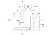
図1に示すように、洗濯機1は全自動型のものであり、外箱10を備える。外箱10は直方体形状で、金属又は合成樹脂により成形されている。外箱10の上面と底面において開口されている。外箱10の上面の開口部には合成樹脂製の上面板11が重ねられて、外箱10にネジで固定されている。 As shown in FIG. 1, the
図1においては、左側が洗濯機1の正面、右側が洗濯機1の背面である。上面板11の上面において洗濯機1の背面側に、上面板11と同じく合成樹脂製のバックパネル12が重ねられている。バックパネル12は外箱10または上面板11にネジで固定される。外箱10の底面の開口部には合成樹脂製のベース13が重ねられている。ベース13は外箱10にネジで固定される。これまでに述べてきたネジはいずれも図示しない。 In FIG. 1, the left side is the front of the
ベース13の四隅には、外箱10を床の上に支えるための脚部14a,14bが設けられている。背面側の脚部14bはベース13に一体成型された固定脚である。正面側の脚部14aは高さ可変のネジ脚であり、脚部14aを回して洗濯機1のレベル出しを行う。 At the four corners of the
上面板11には、後述する洗浄槽として洗濯槽30に被洗浄対象物として洗濯物を投入するための洗濯物投入口15が形設されている。洗濯物投入口15は、蓋16によって上方から覆われる。蓋16は上面板11にヒンジ部17で結合され、垂直面内で回動するように構成されている。 The
外箱10の内部には、水槽20と、脱水槽を兼ねる洗濯槽30とが配置される。水槽20も洗濯槽30も、上面が開口された円筒形のカップの形状を呈している。水槽20と洗濯槽30の各々の軸線は垂直に延びている。水槽20が外側、洗濯槽30が内側となるように同心状に配置されている。水槽20はサスペンション部材21によって吊り下げられる。サスペンション部材21は水槽20の外面下部と外箱10の内面コーナー部とを連結する形で計4箇所に配備されている。水槽20は、サスペンション部材21によって水平面内で揺動できるように支持される。 Inside the
洗濯槽30は、上部の開口部に向かうにつれて内壁面の径が大きくなるように形成されている。言い換えれば、洗濯槽30は上方に向かうにつれて緩やかに広がるテーパ形状の傾斜した内周壁面を有する。洗濯槽30の周壁には、その最上部に環状に配置された複数個の脱水孔31を除き、液体を通すための開口部はない。すなわち、洗濯槽30は、いわゆる「穴なし」タイプである。 The
洗濯槽30の上部開口部の縁には、環状のバランサ32が装着されている。バランサ32は、洗濯物の脱水のため洗濯槽30を高速回転させたときに振動を抑制する働きをする。洗濯槽30の内部底面には、槽内で洗濯水あるいはすすぎ水の流動を生じさせるためのパルセータ33が配置されている。 An
水槽20の下面には駆動ユニット40が装着される。駆動ユニット40は、駆動部としてモータ41、クラッチ機構42およびブレーキ機構43を含む。クラッチ機構42およびブレーキ機構43の中心部から脱水軸44とパルセータ軸45が上向きに突出している。脱水軸44とパルセータ軸45は、脱水軸44を外側、パルセータ軸45を内側とする二重軸構造となっている。脱水軸44は水槽20の中に入り込んだ後、洗濯槽30に連結されて洗濯槽30を支える。パルセータ軸45はさらに洗濯槽30の中に入り込み、パルセータ33に連結してパルセータ33を支える。脱水軸44と水槽20の間、および、脱水軸44とパルセータ軸45の間には、各々、水もれを防ぐためのシール部材が配置されている。 A
バックパネル12の下の空間には、電磁的に開閉する給水弁50が配置されている。給水弁50は、バックパネル12を貫通して上方に突き出す接続管51を有している。接続管51には、水道水などの上水を供給する給水ホース(図示せず)が接続されている。また、給水弁50は給水管52を有している。給水管52の先端は容器状の給水口53に接続する。給水口53は洗濯槽30の内部に臨む位置に配置されている。 A
図2に示すように、容器状の給水口53は上面が開口され、内部が左右に仕切られて2つの区画に分けられている。図2に示す給水口53において左側の区画は洗剤室54であり、右側の区画は仕上剤室55である。洗剤室54は、洗剤を入れておく準備空間である。仕上剤室55は、洗濯用の仕上剤を入れておく準備空間である。洗剤室54の底部正面側には、洗濯槽30に注水する横長の注水口56が設けられている。仕上剤室55にはサイホン部57が設けられている。 As shown in FIG. 2, the container-shaped
サイホン部57は、仕上剤室55の底面から垂直に立ち上がる内管57aと、内管57aにかぶせられるキャップ状の外管57bとからなる。内管57aと外管57bの間には、水の通る隙間が形成されている。内管57aの底部は洗濯槽30の内部に向かって開口する。外管57bの下端は仕上剤室55の底面と所定の隙間を保ち、ここが水の入口になる。内管57aの上端を超えるレベルまで仕上剤室55に水が注ぎ込まれるとサイホンの作用が起こり、仕上剤室55内の水はサイホン部57を通って仕上剤室55から吸い出され、洗濯槽30内へと落下する。 The siphon
給水弁50は、メイン給水弁50aとサブ給水弁50bからなる。メイン給水弁50aは給水部の一例である。接続管51(図1)は、メイン給水弁50aとサブ給水弁50bの両方に共通して接続されている。給水管52は、メイン給水弁50aに接続されたメイン給水管52aと、サブ給水弁50bに接続されたサブ給水管52bとからなる。メイン給水管52aには、金属イオン供給部としてイオン溶出ユニット100が配置されている。 The
メイン給水管52aは洗剤室54に接続され、サブ給水管52bは仕上剤室55に接続されている。すなわち、メイン給水管52aから洗剤室54を通って洗濯槽30に水が供給される経路と、サブ給水管52bから仕上剤室55を通って洗濯槽30に水が供給される経路とは別系統になっている。 The main
図1に示すように、水槽20の底部には、水槽20および洗濯槽30の中の水を外箱10の外に排水する排水ホース60が取り付けられている。排水ホース60には、排水管61および排水管62から水が流れ込む。排水管61は、水槽20の底面の外周寄りの箇所に接続されている。一方、排水管62は、水槽20の底面の中心寄りの箇所に接続されている。 As shown in FIG. 1, a
水槽20の内部底面には、排水管62の接続箇所を内側に囲い込むように環状の隔壁63が固定されている。隔壁63の上部には、環状のシール部材64が取り付けられている。シール部材64が洗濯槽30の底部外面に固定されたディスク65の外周面に接触することにより、水槽20と洗濯槽30との間に独立した排水空間66が形成されている。排水空間66は、洗濯槽30の底部に形設した排水口67を介して洗濯槽30の内部に連通している。 An
排水管62には電磁的に開閉する排水弁68が設けられている。排水管62の排水弁68の上流側にあたる箇所にはエアトラップ69が設けられている。エアトラップ69からは、導圧管70が延び出ている。導圧管70の上端には水位スイッチ71が接続される。水位スイッチ71は、洗濯槽30または水槽20の水量を検知する手段である。 The
外箱10の正面側には制御ユニット80が配置されている。制御ユニット80は、上面板11の下に置かれており、上面板11の上面に設けられた操作/表示部81を通じて使用者からの操作指令を受け、駆動ユニット40、給水弁50および排水弁68に動作指令を発する。また制御ユニット80は操作/表示部81に表示指令を発する。制御ユニット80は、後述するイオン溶出ユニット100の駆動回路を含む。 A
図2に示すように、イオン溶出ユニット100は、メイン給水管52aの途中、すなわち、メイン給水弁50aと洗剤室54の間に配置されている。商品の仕様によっては、サブ給水管52bの途中、すなわちサブ給水弁50bと仕上剤室55の間に配置することとしてもよい。 As shown in FIG. 2, the
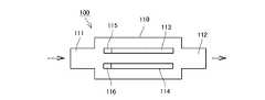
図3と図4に示すように、イオン溶出ユニット100は合成樹脂、シリコン、ゴムなど絶縁材料からなるケース110を有する。ケース110の一方の端部には水の流入口111が形成され、他方の端部に水の流出口112が形成されている。ケース110の内部には、2枚の板状の電極113,114が互いに平行するように、かつ、所定の間隔をあけて配置されている。電極113,114は、抗菌性を有する金属イオンのもととなる金属、すなわち、銀、銅、亜鉛などからなる。 As shown in FIGS. 3 and 4, the
電極113,114には、各々、一方の端部に端子115、116が設けられる。電極113と端子115、電極114と端子116をそれぞれ一体化することが好ましい。電極113と端子115、電極114と端子116をそれぞれ一体化できない場合は、電極と端子の間の接合部およびケース110内の端子部分を合成樹脂でコーティングして水との接触を断ち、電食が生じないようにしておく。端子115,116はケース110の外に突出し、制御ユニット80の中の駆動回路に接続される。 The
ケース110の内部においては、電極113,114の長手方向と平行に水が流れる。ケース110の中に水が存在する状態で電極113,114に所定の電圧を印加すると、電極113,114の陽極側から電極構成金属の金属イオンが溶出する。電極113,114は、例えば、2cm×5cm、厚さ1mm程度の銀プレートとし、5mmの距離を隔てて配置されている。銀電極の場合、陽極側の電極においてAg→Ag++e−の反応が起こり、水中に銀イオンAg+が溶出する。In the
金属イオンを水に供給した後、ケース110の中に水がたまらないようにするために、ケース110の底面において下流側が低くなるように傾斜をつけておくとよい。 After supplying metal ions to the water, in order to prevent water from accumulating in the
次に、洗濯機1(図1)の制御関連の構成を説明する。図5に示すように、洗濯機1は、制御関連の構成として、水位スイッチ71と、操作/表示部81と、制御ユニット80と、モータ41と、給水弁50と、排水弁68とを備える。制御ユニット80は、制御部82と駆動回路120とから構成されている。水位スイッチ71は、洗濯槽30内の水位を検知して制御部82に信号を送信する。使用者が操作/表示部81を操作すると、操作/表示部81から制御部82に信号が送信される。また、制御部82が操作/表示部81に信号を送信して、洗濯行程の残り時間等の情報を表示させる。制御部82は、モータ41に制御信号を送信して、洗濯槽30(図1)の回転数を調整する。制御部82は、給水弁50のメイン給水弁50aとサブ給水弁50bに制御信号を送信して、洗濯槽30内に供給される水の量を調整する。制御部82は、排水弁68に制御信号を送信して、排水弁68を開閉させる。制御部82は、駆動回路120に制御信号を送信して、洗濯槽30内に供給される水中に溶出されるイオンの量を調整する。制御部82が給水弁50と駆動回路120とを制御することによって、洗濯槽30内に供給される金属イオンを含む水の金属イオン濃度が調整される。 Next, a control-related configuration of the washing machine 1 (FIG. 1) will be described. As shown in FIG. 5, the
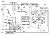
図6に示すように、イオン溶出ユニット100(図3)の駆動回路120においては、商用電源121にトランス122が接続されている。トランス122は、100Vの電圧を所定の電圧に降圧する。トランス122の出力電圧は全波整流回路123によって整流された後、定電圧回路124で定電圧にされる。定電圧回路124には定電流回路125が接続されている。定電流回路125は後述する電極駆動回路150に対して、電極駆動回路150内の抵抗値の変化にかかわらず一定の電流を供給するように動作する。 As shown in FIG. 6, in the
商用電源121には、トランス122と並列に整流ダイオード126が接続される。整流ダイオード126の出力電圧は、コンデンサ127によって平滑化された後、定電圧回路128によって定電圧にされ、マイクロコンピュータ130に供給される。マイクロコンピュータ130はトランス122の一次側コイルの一端と商用電源121との間に接続されたトライアック129を起動し、制御する。 A
電極駆動回路150は、NPN型トランジスタQ1〜Q4とダイオードD1、D2、抵抗R1〜R7が図6に示すように接続されて構成されている。トランジスタQ1とダイオードD1はフォトカプラ151を構成し、トランジスタQ2とダイオードD2はフォトカプラ152を構成する。すなわちダイオードD1、D2はフォトダイオードであり、トランジスタQ1、Q2はフォトトランジスタである。 The
例えば、マイクロコンピュータ130からラインL1にハイレベルの電圧、ラインL2にローレベルの電圧又はOFF(ゼロ電圧)が与えられると、ダイオードD2がONになり、それに付随してトランジスタQ2もONになる。トランジスタQ2がONになると抵抗R3、R4、R7に電流が流れ、トランジスタQ3のベースにバイアスがかかり、トランジスタQ3はONになる。 For example, when a high level voltage is applied to the line L1 from the
一方、このとき、ダイオードD1はOFFなのでトランジスタQ1はOFF、トランジスタQ4もOFFになる。この状態では、陽極側の電極113から陰極側の電極114に向かって電流が流れる。このようにすることにより、イオン溶出ユニット100には陽イオンの金属イオンと陰イオンとが発生する。 On the other hand, since the diode D1 is OFF at this time, the transistor Q1 is OFF and the transistor Q4 is also OFF. In this state, a current flows from the anode-
イオン溶出ユニット100に長時間、同一方向の電流を流すと、図6において陽極側となっている電極113が減耗するとともに、陰極側となっている電極114には水中のカルシウムなどの不純物がスケールとして固着する。また、電極の成分金属の塩化物および硫化物が電極表面に発生する。電極表面に発生する塩化物および硫化物はイオン溶出ユニット100の性能低下をもたらす。そこで、駆動回路120は、電極の極性を反転して電極駆動回路150を運転できるように構成されている。 When a current in the same direction is passed through the
電極の極性を反転するにあたっては、ラインL1,L2の電圧を逆にして、電極113,114を逆方向に電流が流れるように、マイクロコンピュータ130が制御を切り替える。ラインL1,L2の電圧を逆にする場合、トランジスタQ1,Q4がON、トランジスタQ2,Q3がOFFとなる。マイクロコンピュータ130はカウンタ機能を有しており、カウンタが所定カウント数に達する度に上述の切り替えを行う。 In reversing the polarity of the electrodes, the
電極駆動回路150内の抵抗の変化、特に電極113,114の抵抗変化によって、電極間を流れる電流値が減少するなどの事態が生じた場合は、定電流回路125がその出力電圧を上げ、電流の減少を防止する。しかしながら、累積使用時間が長くなるとイオン溶出ユニット100が寿命を迎える。イオン溶出ユニット110が寿命を迎えると、電極の極性反転を実施したり、特定電極である時間を平時よりも長くして電極に付着した不純物を強制的に取り除く電極洗浄モードへの切り替えを実施したり、定電流回路125の出力電圧上昇を実施したりしても、電流の減少を防げなくなる。 When a change in the resistance in the
そこで、イオン溶出ユニット100の電極113、114間を流れる電流を抵抗R7に生じる電圧によって監視し、その電流が所定の最小電流値に至ると、最小電流値を電流検知手段として電流検知回路160が検知する。電流検知回路160が最小電流値を検出したという情報は、フォトカプラ163を構成するフォトダイオードD3からフォトトランジスタQ5を介してマイクロコンピュータ130に伝達される。マイクロコンピュータ130は、ラインL3を介して報知手段として警告報知手段131を駆動し、所定の警告報知を行わせる。警告報知手段131は操作/表示部81又は制御ユニット80に配置されている。 Therefore, the current flowing between the
また、電極駆動回路150内におけるショートなどの事故については、電流が所定の最大電流値以上になったことを検出する電流検知手段として電流検知回路161が用意されている。電流検知回路161の出力に基づいて、マイクロコンピュータ130は警告報知手段131を駆動する。さらに、定電流回路125の出力電圧が予め定めた最小値以下になると、電圧検知回路162が出力電圧を検知する。同様に、マイクロコンピュータ130が警告報知手段131を駆動する。 For an accident such as a short circuit in the
銀イオンにより抗菌防臭効果が認められる指標としては、静菌活性値(標準布との菌数のlog増減値差)が2.0以上を有することである。この実施の形態においては、これに必要な銀イオン濃度として約90ppbとなるようにメイン給水弁50aとイオン溶出ユニット100の駆動制御が行なわれる。 As an index that the antibacterial and deodorizing effect is recognized by silver ions, the bacteriostatic activity value (the difference in the log increase / decrease value of the number of bacteria from the standard cloth) is 2.0 or more. In this embodiment, drive control of the main
次に、洗濯機1(図1)の動作を説明する。 Next, the operation of the washing machine 1 (FIG. 1) will be described.
使用者は、洗濯機1の蓋16を開け、洗濯物投入口15から洗濯槽30の中へ洗濯物を投入する。使用者は、給水口53の洗剤室54に洗剤を入れる。また、必要なら給水口53の仕上剤室55に仕上剤を入れる。仕上剤は洗濯行程の途中で入れられてもよい。 The user opens the
洗剤の投入準備を整えた後、使用者は蓋16を閉じ、操作/表示部81の操作ボタン群を操作して洗濯条件を選ぶ。最後にスタートボタンを押す。 After the preparation of the detergent is prepared, the user closes the
まず、洗濯行程の全体の流れについて説明する。図7のフローチャートにおいて、各行程の判断の主体は制御部82である。 First, the overall flow of the washing process will be described. In the flowchart of FIG. 7, the main body for determining each process is the
図7に示すように、ステップS201では、設定した時刻に洗濯を開始する予約運転の選択がなされているかどうかを制御部82が確認する。予約運転が選択されていればステップS207に進む。予約運転が選択されていなければステップS202に進む。 As shown in FIG. 7, in step S <b> 201, the
ステップS207では、制御部82は、運転開始時刻になったかどうかを判断する。運転開始時刻になっていれば、ステップS202に進む。運転開始時刻になっていなければ、ステップS207に戻る。 In step S207, the
ステップS202では、洗い行程を行うことが選択されているかどうかを制御部82が確認する。洗い行程を行うことが選択されていなければ、直ちにステップS203に進む。洗い行程を行うことが選択されていれば、ステップS300に進み、洗い行程の終了後、ステップS203に進む。ステップS300の洗い行程の内容は図9に示すフローチャートを用いて後述する。 In step S202, the
ステップS203では、すすぎ行程を行うことが選択されているかどうかを制御部82が確認する。すすぎ行程を行うことが選択されていなければ、直ちにステップS204に進む。すすぎ行程を行うことが選択されていれば、ステップS400に進み、すすぎ行程の終了後、ステップS204に進む。ステップS400のすすぎ行程の内容は図10に示すフローチャートを用いて後述する。 In step S203, the
ステップS204では、脱水行程を行うことが選択されているかどうかを制御部82が確認する。脱水行程を行うことが選択されていなければ、直ちにステップS205に進む。脱水行程を行うことが選択されていれば、ステップS500に進み、脱水行程の終了後、ステップS205に進む。ステップS500の脱水行程の内容は図11に示すフローチャートを用いて後述する。 In step S204, the
ステップS205では、イオンコート行程を行うことが選択されているかどうかを制御部82が確認する。イオンコート行程を行うことが選択されていなければ、直ちにステップS206に進む。イオンコート行程を行うことが選択されていれば、ステップS600に進み、イオンコート行程と、ステップS700の最終脱水行程を行った後、ステップS206に進む。ステップS600のイオンコート行程の内容は図12と図13に示すフローチャートを用いて後述する。 In step S205, the
ステップS206では、制御ユニット80、特にその中に含まれる制御部82を構成する演算装置(マイクロコンピュータ)の終了処理が、手順に従って自動的に進められる。また、洗濯行程が完了したことを終了音で報知する。すべてが終了した後、洗濯機1は次の洗濯行程に備えて待機状態に戻る。 In step S206, the termination process of the
図8に示すように、イオンコート行程を行うときの洗濯行程の一例としては、洗い行程、すすぎ行程、脱水行程、イオンコート行程、最終脱水行程、終了処理が順に行われる。洗い行程やすすぎ行程は、複数回行われてもよい。ステップS700において行なわれる最終脱水行程は、図11を用いて後述する脱水行程と同様に行われる。 As shown in FIG. 8, as an example of the washing process when performing the ion coating process, a washing process, a rinsing process, a dehydration process, an ion coating process, a final dehydration process, and an end process are sequentially performed. The washing process and the rinsing process may be performed a plurality of times. The final dehydration process performed in step S700 is performed in the same manner as the dehydration process described later with reference to FIG.
続いて、図9〜図14を用いて、洗い行程、すすぎ行程、脱水行程、および、イオンコート行程の各行程をそれぞれ説明する。 Subsequently, each of the washing process, the rinsing process, the dehydration process, and the ion coating process will be described with reference to FIGS. 9 to 14.
図9に示すように、洗い行程においては、ステップS301で水位検知が行われる。水位検知は、水位スイッチ71が検知している洗濯槽30内の水位データを制御部82に取り込むことによって行われる。 As shown in FIG. 9, in the washing process, the water level is detected in step S301. The water level detection is performed by taking the water level data in the
ステップS302では、容量センシングを行うことが選択されているかどうかを制御部82が確認する。容量センシングを行うことが選択されていなければ、直ちにステップS303に進む。容量センシングを行うことが選択されていれば、ステップS308に進み、容量センシングを行う。この実施の形態においては、イオンコート行程を行うときは、容量センシングが行なわれるものとする。 In step S302, the
ステップS308では、パルセータ33の回転負荷により洗濯物の量を測定する。その後、ステップS303に進む。 In step S308, the amount of laundry is measured by the rotational load of the pulsator 33. Thereafter, the process proceeds to step S303.
ステップ303では、洗濯槽30への給水が行われる。メイン給水弁50aが開かれて、メイン給水管52aおよび給水口53を通じて洗濯槽30に水が注がれる。給水口53の洗剤室54に入れられた洗剤は、水に混じって洗濯槽30に投入される。排水弁68は閉じられている。水位スイッチ71が設定水位を検知したら、メイン給水弁50aは閉じられる。その後、ステップS304に進む。 In step 303, water is supplied to the
ステップS304では、なじませ運転が行われる。パルセータ33が反転回転し、洗濯物と水を攪拌して、洗濯物を水になじませる。このようにすることにより、洗濯物に水を十分に吸収させる。また、洗濯物の各所にとらわれていた空気を逃がす。なじませ運転の結果、水位スイッチ71によって検知される水位が当初より下がったときは、ステップS305に進んで補給水を行う。ステップS305では、メイン給水弁50aが開かれて、水を洗濯槽30内に補給され、設定水位が回復される。 In step S304, a running-in operation is performed. The pulsator 33 rotates in reverse, stirs the laundry and water, and adjusts the laundry to water. By doing so, the laundry is sufficiently absorbed with water. In addition, the air trapped in various parts of the laundry is released. As a result of the running-in operation, when the water level detected by the
また、ステップS304では、使用者が「布質センシング」を行う洗濯コースを選んでいれば、なじませ運転と共に布質センシングが実施される。布質センシングにおいては、なじませ運転を行った後、設定水位からの水位変化が検出され、水位が規定値以上に低下していれば吸水性の高い布質であると制御部82が判断する。 In step S304, if the user has selected a washing course for “clothing sensing”, clothing sensing is performed together with the familiarizing operation. In the cloth quality sensing, after performing the running-in operation, the water level change from the set water level is detected, and if the water level is lower than the specified value, the
ステップS305で補給水がされて、安定した設定水位が得られた後、ステップS306に進む。ステップS306では、使用者の設定に従って、モータ41がパルセータ33を所定のパターンで回転させる。このようにして、洗濯槽30の中に洗濯のための主水流が形成される。この主水流によって洗濯物の洗濯が行われる。脱水軸44にはブレーキ機構43によりブレーキがかけられているので、洗濯水および洗濯物が動いても洗濯槽30は回転しない。 After the replenishing water is supplied in step S305 and a stable set water level is obtained, the process proceeds to step S306. In step S306, the
所定の期間、主水流によって洗濯物が洗濯された後、ステップS307に進む。ステップS307では、パルセータ33が小刻みに反転して洗濯物をほぐし、洗濯槽30の中において洗濯物がバランス良く配分されるようにする。これは、洗濯槽30の脱水回転に備えるためである。 After the laundry is washed by the main water flow for a predetermined period, the process proceeds to step S307. In step S307, the pulsator 33 reverses in small steps to loosen the laundry so that the laundry is distributed in a well-balanced manner in the
続いて、図10に示すフローチャートに基づいて、すすぎ行程を説明する。 Next, the rinsing process will be described based on the flowchart shown in FIG.
図10に示すように、すすぎ行程においては、最初にステップS500の脱水行程が行われるが、脱水行程については図10のフローチャートを用いて後述する。 As shown in FIG. 10, in the rinsing process, the dehydration process in step S500 is first performed. The dehydration process will be described later with reference to the flowchart of FIG.
脱水行程が終了した後、ステップS401に進む。ステップS401では洗濯槽30への給水が行われる。メイン給水弁50aが開かれて、規定水量まで給水される。規定水量は、この実施の形態においては、容量センシングによって求められた洗濯物の重量が、6kg以上のときには45L、3kg以上6kg未満のときには37L、1kg以上3kg未満のときには23K、1kg未満のときには20Lであるとする。 After the dehydration process is completed, the process proceeds to step S401. In step S401, water is supplied to the
次に、ステップS402に進む。ステップS402ではなじませ運転が行われる。ステップS402のなじませ運転では、ステップS500の脱水行程で洗濯槽30に貼り付いた洗濯物を剥離させ、水になじませ、洗濯物に水を十分に吸収させる。 Next, the process proceeds to step S402. In step S402, the running-in operation is performed. In the running-in operation in step S402, the laundry attached to the
ステップS402のなじませ運転の後、ステップS403に進む。なじませ運転の結果、水位スイッチ71によって検知される水位が当初より下がったときは、ステップS403に進んで補給水を行う。ステップS403では、メイン給水弁50aが開かれて、水を洗濯槽30内に補給され、設定水位が回復される。 After the running-in operation in step S402, the process proceeds to step S403. When the water level detected by the
ステップS403で補給水がされて、安定した設定水位が得られた後、ステップS404に進む。ステップS404では、使用者の設定に従って、モータ41がパルセータ33を所定のパターンで回転させる。このようにして、洗濯槽30の中に洗濯のための主水流が形成される。この主水流によって洗濯物の洗濯が行われる。脱水軸44にはブレーキ機構43によりブレーキがかけられているので、洗濯水および洗濯物が動いても洗濯槽30は回転しない。 After replenishing water in step S403 and obtaining a stable set water level, the process proceeds to step S404. In step S404, the
所定の期間、主水流によって洗濯物が洗濯された後、ステップS405に進む。ステップS405では、パルセータ33が小刻みに反転して洗濯物をほぐし、洗濯槽30の中において洗濯物がバランス良く配分されるようにする。これは、洗濯槽30の脱水回転に備えるためである。 After the laundry is washed by the main water flow for a predetermined period, the process proceeds to step S405. In step S405, the pulsator 33 reverses in small increments to loosen the laundry so that the laundry is distributed in a well-balanced manner in the
上述の説明では、洗濯槽30の中にすすぎ水をためておいてすすぎを行う「ためすすぎ」を実行するものとしたが、常に新しい水を補給する「注水すすぎ」、あるいは洗濯槽30を低速回転させながら給水口53より洗濯物に水を注ぎかける「シャワーすすぎ」を行ってもよい。 In the above description, it is assumed that “rinse rinsing” is performed in which the rinse water is stored in the
続いて、図11に示すフローチャートを用いて、脱水行程の内容を説明する。まず、ステップS501で排水弁68が開かれる。洗濯槽30の中の洗濯水は、排水空間66を通じて排水される。排水弁68は、脱水行程中、開かれたままである。 Next, the contents of the dehydration process will be described using the flowchart shown in FIG. First, in step S501, the
洗濯物から大部分の洗濯水が除かれたところで、クラッチ機構42とブレーキ機構43とが切り替えられる。クラッチ機構42とブレーキ機構43の切り替えのタイミングは、排水開始前であってもよいし、排水と同時でもよい。 When most of the washing water is removed from the laundry, the
次に、ステップS502で、低速脱水が行われる。低速脱水は、モータ41が脱水軸44を回転させることによって行われる。モータ41が脱水軸44を回転させることによって、洗濯槽30が脱水回転させられる。パルセータ33も洗濯槽30とともに回転させられる。 Next, low speed dehydration is performed in step S502. The low speed dewatering is performed by the
ステップS503では、高速脱水が行われる。高速脱水は、モータ41による脱水軸44の回転速度を高めることによって行われる。洗濯槽30が高速で回転させられると、洗濯物は遠心力で洗濯槽30の内周壁に押しつけられる。洗濯物に含まれていた洗濯水も、遠心力によって洗濯槽30の周壁内面に集まる。洗濯槽30はテーパ状に上方に広がっているので、遠心力を受けた洗濯水は洗濯槽30の内面に沿って上昇する。洗濯水は、洗濯槽30の上端にたどりついたところで脱水孔31から放出される。脱水孔31を離れた洗濯水は水槽20の内面にたたきつけられ、水槽20の内面を伝って水槽20の底部に流れ落ちる。そして、排水管61と、それに続く排水ホース60を通って外箱10の外に排出される。 In step S503, high-speed dehydration is performed. High speed dewatering is performed by increasing the rotation speed of the dewatering
ステップS504では、制御部82はモータ41への通電を断ち、停止処理を行う。 In step S504, the
次に、図12と図13に示すフローチャートを用いて、イオンコート行程の内容について説明する。 Next, the contents of the ion coating process will be described using the flowcharts shown in FIGS.
イオンコート行程を行う場合には、まず、図9の洗い行程のステップS308において行なわれた容量センシングの結果に基づいて、第2の目標回転数(Rh)と、金属イオンを含む水(金属イオン水)を洗濯槽30内に供給する所定の時間(L)とが決定される。 When performing the ion coating process, first, based on the result of the capacitive sensing performed in step S308 of the washing process of FIG. 9, the second target rotation speed (Rh) and water containing metal ions (metal ions) A predetermined time (L) for supplying water into the
図12に示すように、ステップS601では、洗濯槽30内に収容されている洗濯物の重量が6kg以上であるかどうかを制御部82が判断する。洗濯槽30内に収容されている洗濯物の重量が6kg以上であれば、ステップS602に進む。洗濯槽30内に収容されている洗濯物の重量が6kg未満であれば、ステップS603に進む。 As shown in FIG. 12, in step S601, the
ステップS602では、イオンコート行程おける洗濯機30の第2の目標回転数を300rpmに設定する。また、第2の目標回転数を決定する変数Rhに、300rpmの回転数に相当するデータrh4が代入される。同時に、メイン給水弁50aと駆動回路120の駆動時間を決定する変数Lに、1分50秒に相当するデータl4が代入される。このようにすることにより、金属イオンを含む水が27L、洗濯槽30内に供給される。 In step S602, the second target rotational speed of the
ステップS603では、洗濯槽30内に収容されている洗濯物の重量が3kg以上であるかどうかを制御部82が判断する。洗濯槽30内に収容されている洗濯物の重量が3kg以上であれば、ステップS604に進む。洗濯槽30内に収容されている洗濯物の重量が3kg未満であれば、ステップS605に進む。 In step S603, the
ステップS604では、イオンコート行程おける洗濯槽30の第2の目標回転数を250rpmに設定する。また、第2の目標回転数を決定する変数Rhに、250rpmの回転数に相当するデータrh3が代入される。同時に、メイン給水弁50aと駆動回路120の駆動時間を決定する変数Lに、1分30秒に相当するデータl3が代入される。このようにすることにより、金属イオンを含む水が22L、洗濯槽30内に供給される。 In step S604, the second target rotational speed of the
ステップS605では、洗濯槽30内に収容されている洗濯物の重量が1kg以上であるかどうかを制御部82が判断する。洗濯槽30内に収容されている洗濯物の重量が1kg以上であれば、ステップS606に進む。洗濯槽30内に収容されている洗濯物の重量が1kg未満であれば、ステップS607に進む。 In step S605, the
ステップS606では、イオンコート行程おける洗濯槽30の第2の目標回転数を200rpmに設定する。また、第2の目標回転数を決定する変数Rhに、200rpmの回転数に相当するデータrh2が代入される。同時に、メイン給水弁50aと駆動回路120の駆動時間を決定する変数Lに、1分00秒に相当するデータl2が代入される。このようにすることにより、金属イオンを含む水が14L、洗濯槽30内に供給される。 In step S606, the second target rotational speed of the
ステップS607では、イオンコート行程おける洗濯槽30の第2の目標回転数を200rpmに設定する。また、第2の目標回転数を決定する変数Rhに、200rpmの回転数に相当するデータrh1が代入される。同時に、メイン給水弁50aと駆動回路120の駆動時間を決定する変数Lに、50秒に相当するデータl1が代入される。このようにすることにより、金属イオンを含む水が12L、洗濯槽30内に供給される。 In step S607, the second target rotational speed of the
なお、上述の金属イオンを含む水の供給量については、一般的な家庭での水道給水量である約14L/分を目安に計算した値である。 In addition, about the supply_amount | feed_rate of the water containing the above-mentioned metal ion, it is the value calculated on the basis of about 14L / min which is the amount of water supply in a general household.
表1は、洗濯槽30内に収容される衣類の量が6kg以上、3kg以上6kg未満、1kg以上3kg未満、1kg未満のそれぞれの場合について、規定水量と、第1と第2の回転数と、洗濯槽30に金属イオンを含む水を供給する時間と、洗濯槽30に供給される金属イオンを含む水の量とを示す表である。 Table 1 shows that the amount of clothing accommodated in the

表1に示すように、イオンコート行程において洗濯槽30に供給される金属イオンを含む水は、規定水量よりも少なく、規定水量の約60%である。 As shown in Table 1, the amount of water containing metal ions supplied to the
次に、イオンコート行程における制御処理について説明する。 Next, the control process in the ion coating process will be described.
図13に示すように、イオンコート行程においては、ステップS611で、洗濯槽30の第1の目標回転数(RI)が設定され、制御部82がモータ41を駆動させる。第1の目標回転数(RI)としては、この実施の形態においては、200rpmが設定されるものとする。第1の目標回転数(RI)は、洗濯槽30の回転中に金属イオンを含む水の供給を行う際に、洗濯槽30内に供給された水が回転中の洗濯槽30に当たることで発生する水はね音が耳障りにならないような回転数として設定されている。 As shown in FIG. 13, in the ion coating process, in step S611, the first target rotational speed (RI) of the
ステップS612では、洗濯槽30の回転数が、第1の目標回転数(RI)である200rpmに達したかどうかを制御部82が判断する。洗濯槽30の回転数が第1の目標回転数(RI)以上、すなわち、200rpm以上であれば、ステップS613に進む。洗濯槽30の回転数が第1の目標回転数(RI)以上でなければ、ステップS612に戻る。 In step S612, the
ステップS613では、制御部82が給水弁50のうちメイン給水弁50aと駆動回路120に制御信号を送信して、メイン給水弁50aが開かれ、駆動回路120によってイオン溶出ユニット100が駆動される。洗濯槽30には、金属イオンを含む水が供給される。 In step S613, the
ステップS614では、制御部82は。メイン給水弁50aが開かれてイオン溶出ユニット100が駆動されてから所定の時間(L)が経過したかどうかを判断する。所定の時間(L)が経過していれば、ステップS615に進む。所定の時間(L)が経過していなければ、ステップS614に戻る。所定の時間(L)は、図12に示すフローチャートに従って決定された時間である。 In step S614, the
ステップS614では、時間(L)が経過したかどうかを制御部82が確認する。時間(L)が経過していれば、ステップS615に進む。時間(L)が経過していなければ、ステップS614に戻る。 In step S614, the
ステップS615では、制御部82がメイン給水弁50aと駆動回路120に制御信号を送信し、メイン給水弁50aを閉じ、駆動回路120によるイオン溶出ユニット100の動作を停止させる。メイン給水弁50aが閉じられ、イオン溶出ユニット100の駆動が停止されることによって、洗濯槽30内への金属イオンを含む水の供給が停止される。 In step S615, the
ステップS613からステップS615の行程は、第1の行程の一例である。 The process from step S613 to step S615 is an example of a first process.
ステップS616では、洗濯槽30の回転制御における第2の目標回転数データ(変数Rh)として、容量センシングにおいて衣類の量に応じて決定したデータ(rh4〜rh1)を設定する。これにより、洗濯槽30の回転はこの第2の目標回転数に向かって制御される。第2の目標回転数(Rh)は、図12に示すフローチャートに従って決定された回転数である。 In step S616, data (rh4 to rh1) determined according to the amount of clothes in the capacity sensing is set as the second target rotation speed data (variable Rh) in the rotation control of the
ステップS617では、洗濯槽30の回転数が、第2の目標回転数(Rh)に達したかどうかを制御部82が判断する。洗濯槽30の回転数が第2の目標回転数(Rh)以上であれば、ステップS618に進む。洗濯槽30の回転数が第2の目標回転数(Rh)以上でなければ、ステップS617に戻る。洗濯槽30の回転数が第2の目標回転数に達すると、洗濯物が金属イオンを含む水に浸された状態で洗濯槽30が回転されることになる。 In step S617, the
ステップS618では、制御部82は、洗濯槽30の回転数が第2の目標回転数に達してから、所定の浸漬時間が経過したかどうかを判断する。金属イオンを洗濯物に十分に付着させるために、この浸漬時間は5分以上であることが望ましい。所定の浸漬時間が経過していなければ、ステップS618に戻る。所定の浸漬時間が経過していれば、イオンコート行程を終了する。 In step S618, the
ステップS616からステップS618の行程は、第2の行程の一例である。 The process from step S616 to step S618 is an example of a second process.
その後、図8に示す最終脱水行程に進み、最終脱水行程が終了すれば、すべての洗濯行程が終了する。 Thereafter, the process proceeds to the final dehydration process shown in FIG. 8, and when the final dehydration process is completed, all the washing processes are completed.
このように、イオンコート行程においては、洗濯物のすすぎ行程において用いられる規定水量に対して、約60%の水量で、洗濯物を金属イオン水(金属イオンを含む水)に浸漬させ、金属イオンを洗濯物に付着させることができる。 As described above, in the ion coating process, the laundry is immersed in metal ion water (water containing metal ions) at a water amount of about 60% with respect to the specified water amount used in the rinse process of the laundry. Can be attached to the laundry.
例えば、銀イオンは抗菌防臭効果を得ることのできる金属イオンである。イオンコート行程において、金属イオンを洗濯物に付着させるための水量を、規定水量の60%にすることによって、イオン濃度を確保するために必要な銀イオンの溶出量も従来の約60%程度となる。このようにすることにより。イオン溶出ユニット100内に搭載される板状電極113、114の大きさを約60%程度に削減することが可能となる。 For example, silver ions are metal ions that can obtain an antibacterial deodorizing effect. In the ion coating process, by making the amount of water for attaching metal ions to the
なお、この実施の形態においては、洗濯機としては「穴なし」槽を備える、いわゆる縦型洗濯機を用いて説明したが、洗濯機は、横型洗濯機など、他の洗濯機であってもよい。 In this embodiment, the washing machine has been described using a so-called vertical washing machine having a “no hole” tub, but the washing machine may be another washing machine such as a horizontal washing machine. Good.
以上のように、洗濯機1は、洗濯槽30と、モータ41と、メイン給水弁50aと、イオン溶出ユニット100と、制御部82とを備える。洗濯槽30は洗濯物を収容する。モータ41は洗濯槽30を回転させる。メイン給水弁50aは洗濯槽30の内部に水を供給する。イオン溶出ユニット100はメイン給水弁50aによって洗濯槽30の内部に供給される水に金属イオンを加える。 As described above, the
制御部82は、洗い行程と、すすぎ行程と、脱水行程と、イオンコート行程とを順に行うように、モータ41とメイン給水弁50aとイオン溶出ユニット100とを制御する。洗い行程においては、洗濯物を水で洗う。すすぎ行程においては、洗い行程で洗われた洗濯物を洗濯物の量に見合った規定水量の水ですすぐ。脱水行程においては、すすぎ行程ですすがれた洗濯物を脱水する。 The
イオンコート行程は、第1の行程と第2の行程とを含む。第1の行程においては、脱水行程で脱水された洗濯物に、規定水量よりも少ない水量の金属イオンを含む水が供給される。第2の行程においては、第1の行程において金属イオンを含む水が供給された洗濯槽30を、洗濯槽30が回転したときに洗濯物が金属イオンを含む水に浸る程度の回転数で回転させる。 The ion coating process includes a first process and a second process. In the first step, water containing metal ions having a smaller amount of water than the specified amount is supplied to the laundry dehydrated in the dehydration step. In the second stroke, the
洗い行程において水で洗われた洗濯物は、すすぎ行程において水ですすがれる。洗い行程で洗われた洗濯物には洗剤等が付着しているので、すすぎ行程においては、規定水量の水で洗濯物がすすがれる。規定水量の水は、洗濯物をすすぐために十分な水量であるとする。このようにすることにより、洗濯物に付着している洗剤等が除去される。続いて、脱水行程において、洗濯物が脱水される。 The laundry washed with water in the washing process is rinsed with water in the rinsing process. Since the detergent or the like is attached to the laundry washed in the washing process, the laundry is rinsed with a specified amount of water in the rinsing process. The specified amount of water is assumed to be sufficient to rinse the laundry. By doing in this way, the detergent etc. which have adhered to the laundry are removed. Subsequently, the laundry is dehydrated in the dehydration process.
次に、イオンコート行程の第1の行程において、洗濯物には金属イオンを含む水が供給される。金属イオンを含む水は、規定水量よりも少ない水量だけ供給される。そのため、そのままでは洗濯物の全体が金属イオンを含む水に十分に浸されない。 Next, in the first step of the ion coating step, water containing metal ions is supplied to the laundry. The water containing metal ions is supplied in an amount less than the specified amount. Therefore, as it is, the entire laundry is not sufficiently immersed in water containing metal ions.
イオンコート行程の第2の行程においては、洗濯槽30が回転させられる。洗濯槽30が回転させられると、洗濯槽30に収容されている洗濯物と金属イオンを含む水に遠心力が働く。遠心力によって、金属イオンを含む水が洗濯槽30内を移動して、洗濯物を浸す。洗濯槽30は、洗濯槽30が回転したときに洗濯物が金属イオンを含む水に浸る程度の回転数で回転させられる。このような回転数で洗濯槽30が回転させられることによって、洗濯槽30内に収容されている洗濯物が、規定水量よりも少ない水量の金属イオンを含む水によって浸される。金属イオンを含む水に浸された洗濯物には金属イオンが付着する。 In the second stroke of the ion coating stroke, the
また、洗濯槽30は、洗濯槽30が回転したときに洗濯物が金属イオンを含む水に浸る程度の回転数で回転させられるので、例えば洗濯槽30の上部に穴が形成されている洗濯槽30を用いても、遠心力によって金属イオンを含む水が洗濯槽30の外部に排出されない。 Further, since the
このようにすることにより、規定水量の金属イオンを含む水を使用する場合と比較して金属イオンの使用量を抑えて、効率よく洗濯物に金属イオンを付着させることが可能な洗濯機1を提供することができる。 By doing in this way, the
また、洗濯機1は、第1の行程においては、洗濯物の量に基づいて金属イオンを含む水の量を変更するように、制御部82がモータ41とメイン給水弁50aとイオン溶出ユニット100とを制御する。 Further, in the
第1の行程においては、例えば、洗濯槽30に収容されている洗濯物の量が多いときには金属イオンを含む水の量を増加させて、金属イオンを含む水に洗濯物をむらなく浸すことができる。 In the first step, for example, when the amount of laundry stored in the
また、洗濯機1は、第2の行程においては、洗濯物の量に基づいて洗濯槽30の回転数を変更するように、制御部82がモータ41とメイン給水弁50aとイオン溶出ユニット100とを制御する。 In addition, in the second process, the
洗濯槽30を高速で回転させることによって脱水する場合には、脱水行程の終了後に、洗濯槽30の内周壁面に洗濯物が貼りつくことがある。洗濯槽30の底面からの洗濯物の高さは、洗濯物の量が多いほど高くなる。そこで、第2の行程においては、例えば、洗濯物の量が多いときには洗濯槽30の回転数を増加させて、遠心力によって金属イオンを含む水を洗濯槽30の内周壁面に沿って上昇させる。このようにすることにより、金属イオンを含む水に洗濯物をむらなく浸すことができる。 When dewatering is performed by rotating the
また、イオンコート行程においては、洗濯槽30を第1の目標回転数で回転させる前に、洗濯槽30に金属イオンを含む水を供給してもよい。 In the ion coating process, water containing metal ions may be supplied to the
図14に示すように、イオンコート行程の別の例としては、ステップS621で、制御部82が給水弁50のうちメイン給水弁50aと駆動回路120に制御信号を送信して、メイン給水弁50aが開かれ、駆動回路120によってイオン溶出ユニット100が駆動される。洗濯槽30には、金属イオンを含む水が供給される。このとき、洗濯槽30はまだ回転されておらず、静止している。 As shown in FIG. 14, as another example of the ion coating process, in step S621, the
ステップS622では、制御部82は、メイン給水弁50aが開かれてイオン溶出ユニット100が駆動されてから所定の時間(L)が経過したかどうかを判断する。所定の時間(L)が経過していれば、ステップS623に進む。所定の時間(L)が経過していなければ、ステップS622に戻る。所定の時間(L)は、図12に示すフローチャートに従って決定された時間である。 In step S622, the
ステップS623では、制御部82がメイン給水弁50aと駆動回路120に制御信号を送信し、メイン給水弁50aを閉じ、駆動回路120によるイオン溶出ユニット100の動作を停止させる。メイン給水弁50aが閉じられ、イオン溶出ユニット100の駆動が停止されることによって、洗濯槽30内への金属イオンを含む水の供給が停止される。 In step S623, the
ステップS621からステップS623の行程は、第1の行程の一例である。 The process from step S621 to step S623 is an example of a first process.
次に、ステップS624で、洗濯槽30の第1の目標回転数(RI)が設定され、制御部82がモータ41を駆動させる。第1の目標回転数(RI)としては、この実施の形態においては、200rpmが設定されるものとする。 Next, in step S624, the first target rotational speed (RI) of the
ステップS625では、洗濯槽30の回転数が、第1の目標回転数(RI)である200rpmに達したかどうかを制御部82が判断する。洗濯槽30の回転数が第1の目標回転数(RI)以上、すなわち、200rpm以上であれば、ステップS626に進む。洗濯槽30の回転数が第1の目標回転数(RI)以上でなければ、ステップS625に戻る。 In step S625, the
ステップS626では、洗濯槽30の回転制御における第2の目標回転数データ(変数Rh)として、容量センシングにおいて衣類の量に応じて決定したデータ(rh4〜rh1)を設定する。これにより、洗濯槽30の回転はこの第2の目標回転数に向かって制御される。第2の目標回転数(Rh)は、図12に示すフローチャートに従って決定された回転数である。 In step S626, data (rh4 to rh1) determined according to the amount of clothes in the capacity sensing is set as the second target rotation speed data (variable Rh) in the rotation control of the
ステップS627では、洗濯槽30の回転数が、第2の目標回転数(Rh)に達したかどうかを制御部82が判断する。洗濯槽30の回転数が第2の目標回転数(Rh)以上であれば、ステップS628に進む。洗濯槽30の回転数が第2の目標回転数(Rh)以上でなければ、ステップS627に戻る。洗濯槽30の回転数が第2の目標回転数に達すると、洗濯物が金属イオンを含む水に浸された状態で洗濯槽30が回転されることになる。 In step S627, the
ステップS628では、制御部82は、洗濯槽30の回転数が第2の目標回転数に達してから、所定の浸漬時間が経過したかどうかを判断する。金属イオンを洗濯物に十分に付着させるために、この浸漬時間は5分以上であることが望ましい。所定の浸漬時間が経過していなければ、ステップS628に戻る。所定の浸漬時間が経過していれば、イオンコート行程を終了する。 In step S628, the
ステップS624からステップS628の行程は、第2の行程の一例である。 The process from step S624 to step S628 is an example of a second process.
その後、図8に示す最終脱水行程に進み、最終脱水行程が終了すれば、すべての洗濯行程が終了する。 Thereafter, the process proceeds to the final dehydration process shown in FIG. 8, and when the final dehydration process is completed, all the washing processes are completed.
以上のように、洗濯機1は、第1の行程においては、静止している洗濯槽30に金属イオンを含む水が供給されるように、制御部82がモータ41とメイン給水弁50aと駆動回路120とを制御してもよい。 As described above, in the
このようにすることにより、洗濯槽30内の水位を容易に正確に検知することができるので、より正確に金属イオンを含む水の供給量を制御することが可能になる。 By doing in this way, since the water level in the
以上に開示された実施の形態はすべての点で例示であって制限的なものではないと考慮されるべきである。本発明の範囲は、以上の実施の形態ではなく、特許請求の範囲によって示され、特許請求の範囲と均等の意味および範囲内でのすべての修正と変形を含むものである。 The embodiment disclosed above should be considered as illustrative in all points and not restrictive. The scope of the present invention is shown not by the above embodiments but by the scope of claims, and includes all modifications and variations within the meaning and scope equivalent to the scope of claims.
1:洗濯機、30:洗濯槽、41:モータ、50a:メイン給水弁、82:制御部、100:イオン溶出ユニット。 1: washing machine, 30: washing tub, 41: motor, 50a: main water supply valve, 82: control unit, 100: ion elution unit.
Claims (4)
Translated fromJapanese前記容器を回転させる駆動部と、
前記容器の内部に水を供給する給水部と、
前記給水部によって前記容器の内部に供給される水に金属イオンを加える金属イオン供給部と、
前記駆動部と前記給水部と前記金属イオン供給部とを制御する制御部とを備え、
前記制御部は、
被洗浄対象物を水で洗う洗い行程と、
前記洗い行程で洗われた被洗浄対象物を被洗浄対象物の量に見合った規定水量の水ですすぐすすぎ行程と、
前記すすぎ行程ですすがれた被洗浄対象物を脱水する脱水行程と、
第1の行程と第2の行程とを含むイオン供給行程とを順に行い、
前記第1の行程においては、前記脱水行程で脱水された被洗浄対象物に、前記規定水量よりも少ない水量の金属イオンを含む水が供給され、
前記第2の行程においては、前記第1の行程において金属イオンを含む水が供給された容器を、前記容器が回転したときに被洗浄対象物が金属イオンを含む水に浸る程度の回転数で回転させるように、前記駆動部と前記給水部と前記金属イオン供給部とを制御する、洗濯機。A container for storing an object to be cleaned;
A drive for rotating the container;
A water supply unit for supplying water into the container;
A metal ion supply unit for adding metal ions to water supplied into the container by the water supply unit;
A controller that controls the drive unit, the water supply unit, and the metal ion supply unit;
The controller is
A washing process of washing the object to be washed with water;
Rinse the object to be cleaned washed in the washing process with a specified amount of water corresponding to the amount of the object to be cleaned;
A dehydration step of dehydrating the object to be cleaned rinsed in the rinsing step;
Performing an ion supply process including a first process and a second process in order,
In the first step, the water to be cleaned dehydrated in the dehydration step is supplied with water containing metal ions having a water amount smaller than the specified water amount,
In the second stroke, the container supplied with water containing metal ions in the first stroke is rotated at such a speed that the object to be cleaned is immersed in water containing metal ions when the container rotates. A washing machine that controls the drive unit, the water supply unit, and the metal ion supply unit to rotate.
In the second step, the control unit controls the drive unit, the water supply unit, and the metal ion supply unit so as to change the rotation speed of the container based on the amount of the object to be cleaned. The washing machine according to any one of claims 1 to 3.
Priority Applications (2)
| Application Number | Priority Date | Filing Date | Title |
|---|---|---|---|
| JP2009170009AJP2011019873A (en) | 2009-07-21 | 2009-07-21 | Washing machine |
| PCT/JP2010/060258WO2011010518A1 (en) | 2009-07-21 | 2010-06-17 | Washing machine |
Applications Claiming Priority (1)
| Application Number | Priority Date | Filing Date | Title |
|---|---|---|---|
| JP2009170009AJP2011019873A (en) | 2009-07-21 | 2009-07-21 | Washing machine |
Publications (1)
| Publication Number | Publication Date |
|---|---|
| JP2011019873Atrue JP2011019873A (en) | 2011-02-03 |
Family
ID=43498994
Family Applications (1)
| Application Number | Title | Priority Date | Filing Date |
|---|---|---|---|
| JP2009170009APendingJP2011019873A (en) | 2009-07-21 | 2009-07-21 | Washing machine |
Country Status (2)
| Country | Link |
|---|---|
| JP (1) | JP2011019873A (en) |
| WO (1) | WO2011010518A1 (en) |
Cited By (1)
| Publication number | Priority date | Publication date | Assignee | Title |
|---|---|---|---|---|
| JP2015029842A (en)* | 2013-08-06 | 2015-02-16 | シャープ株式会社 | Washing machine |
Families Citing this family (2)
| Publication number | Priority date | Publication date | Assignee | Title |
|---|---|---|---|---|
| KR102420689B1 (en) | 2010-02-26 | 2022-07-15 | 가부시키가이샤 한도오따이 에네루기 켄큐쇼 | Semiconductor device |
| US9765464B2 (en) | 2015-01-22 | 2017-09-19 | Haier Us Appliance Solutions, Inc. | Washing machine appliance |
Citations (6)
| Publication number | Priority date | Publication date | Assignee | Title |
|---|---|---|---|---|
| JPH02225185A (en)* | 1989-02-27 | 1990-09-07 | Nissan Motor Co Ltd | Trunk lid opening/closing structure |
| JPH02255185A (en)* | 1989-03-29 | 1990-10-15 | Matsushita Electric Ind Co Ltd | Washing machine controller |
| JP2003019391A (en)* | 2001-07-09 | 2003-01-21 | Sansha Electric Mfg Co Ltd | Washing method and device for the same |
| JP2006102528A (en)* | 2003-08-08 | 2006-04-20 | Sharp Corp | Water supply device, water supply method, water irrigation device provided with water supply device, and washing machine provided with water supply device |
| JP2007044070A (en)* | 2005-08-05 | 2007-02-22 | Sharp Corp | Washing machine |
| JP2008012013A (en)* | 2006-07-05 | 2008-01-24 | Sharp Corp | Cleaning device |
- 2009
- 2009-07-21JPJP2009170009Apatent/JP2011019873A/enactivePending
- 2010
- 2010-06-17WOPCT/JP2010/060258patent/WO2011010518A1/enactiveApplication Filing
Patent Citations (6)
| Publication number | Priority date | Publication date | Assignee | Title |
|---|---|---|---|---|
| JPH02225185A (en)* | 1989-02-27 | 1990-09-07 | Nissan Motor Co Ltd | Trunk lid opening/closing structure |
| JPH02255185A (en)* | 1989-03-29 | 1990-10-15 | Matsushita Electric Ind Co Ltd | Washing machine controller |
| JP2003019391A (en)* | 2001-07-09 | 2003-01-21 | Sansha Electric Mfg Co Ltd | Washing method and device for the same |
| JP2006102528A (en)* | 2003-08-08 | 2006-04-20 | Sharp Corp | Water supply device, water supply method, water irrigation device provided with water supply device, and washing machine provided with water supply device |
| JP2007044070A (en)* | 2005-08-05 | 2007-02-22 | Sharp Corp | Washing machine |
| JP2008012013A (en)* | 2006-07-05 | 2008-01-24 | Sharp Corp | Cleaning device |
Cited By (1)
| Publication number | Priority date | Publication date | Assignee | Title |
|---|---|---|---|---|
| JP2015029842A (en)* | 2013-08-06 | 2015-02-16 | シャープ株式会社 | Washing machine |
Also Published As
| Publication number | Publication date |
|---|---|
| WO2011010518A1 (en) | 2011-01-27 |
Similar Documents
| Publication | Publication Date | Title |
|---|---|---|
| JP4476274B2 (en) | Washing machine | |
| JP3957619B2 (en) | Ion elution unit and equipment equipped with the same | |
| JP4017504B2 (en) | Washing machine | |
| JP3957616B2 (en) | Ion elution unit and equipment equipped with the same | |
| JP2004321320A (en) | Washing machine | |
| JP2004105692A (en) | Washing machine | |
| JP3957583B2 (en) | Washing machine | |
| JP4010887B2 (en) | Washing machine | |
| WO2011010518A1 (en) | Washing machine | |
| JP2007330320A (en) | Washing machine | |
| JP3953381B2 (en) | Ion elution unit and washing machine equipped with the same | |
| JP4159399B2 (en) | Washing machine | |
| JP3638018B1 (en) | Washing machine | |
| JP3957655B2 (en) | Washing machine with drying function | |
| JP4024257B2 (en) | Washing machine | |
| JP2004321306A (en) | Washing machine | |
| JP2006191965A (en) | Washing machine | |
| JP4417404B2 (en) | Washing machine | |
| JP2004057855A (en) | Ion elution unit and washing machine equipped with the same | |
| JP2004216199A (en) | Ion elution unit, equipment equipped with ion elution unit, and washing machine equipped with ion elution unit | |
| JP3957617B2 (en) | Washing machine | |
| JP2005065880A (en) | Equipment equipped with an ion elution unit | |
| JP2004033996A (en) | Ion elution unit and washing machine equipped with the same | |
| AU2007231905A1 (en) | Ion eluting unit and device provided with same |
Legal Events
| Date | Code | Title | Description |
|---|---|---|---|
| A521 | Written amendment | Free format text:JAPANESE INTERMEDIATE CODE: A523 Effective date:20101215 | |
| A02 | Decision of refusal | Free format text:JAPANESE INTERMEDIATE CODE: A02 Effective date:20110208 |