JP2011019682A - Display case - Google Patents
Display caseDownload PDFInfo
- Publication number
- JP2011019682A JP2011019682AJP2009166567AJP2009166567AJP2011019682AJP 2011019682 AJP2011019682 AJP 2011019682AJP 2009166567 AJP2009166567 AJP 2009166567AJP 2009166567 AJP2009166567 AJP 2009166567AJP 2011019682 AJP2011019682 AJP 2011019682A
- Authority
- JP
- Japan
- Prior art keywords
- guide plate
- light guide
- display case
- panel
- plate unit
- Prior art date
- Legal status (The legal status is an assumption and is not a legal conclusion. Google has not performed a legal analysis and makes no representation as to the accuracy of the status listed.)
- Granted
Links
- 238000005286illuminationMethods0.000claimsabstractdescription27
- 230000002093peripheral effectEffects0.000claimsdescription4
- 238000004519manufacturing processMethods0.000abstractdescription15
- 239000011521glassSubstances0.000description7
- 239000000463materialSubstances0.000description7
- 239000000758substrateSubstances0.000description4
- 238000007792additionMethods0.000description3
- 238000009792diffusion processMethods0.000description3
- 239000000853adhesiveSubstances0.000description2
- 230000001070adhesive effectEffects0.000description2
- 230000000694effectsEffects0.000description2
- 239000012780transparent materialSubstances0.000description2
- 239000004925Acrylic resinSubstances0.000description1
- 229920000178Acrylic resinPolymers0.000description1
- 238000005562fadingMethods0.000description1
- 238000012986modificationMethods0.000description1
- 230000004048modificationEffects0.000description1
- 238000000465mouldingMethods0.000description1
- 230000003287optical effectEffects0.000description1
- 239000013307optical fiberSubstances0.000description1
- 238000003672processing methodMethods0.000description1
- 229920003002synthetic resinPolymers0.000description1
- 239000000057synthetic resinSubstances0.000description1
Images


Landscapes
- Planar Illumination Modules (AREA)
- Freezers Or Refrigerated Showcases (AREA)
- Arrangement Of Elements, Cooling, Sealing, Or The Like Of Lighting Devices (AREA)
Abstract
Translated fromJapaneseDescription
Translated fromJapanese本発明は、床面に設置された展示台と、該展示台の上方に形成された展示空間の周囲が透明パネルにより囲まれ、かつ各透明パネルの上面開口部を上面パネルで覆ってなるケース本体と、を備える展示ケースに関する。 The present invention is a case in which a display stand installed on a floor surface, a display space formed above the display stand is surrounded by a transparent panel, and the top opening of each transparent panel is covered with the top panel. A display case including the main body.
従来の展示ケースは、上、中、下の3段の部屋を持つ直方体形状をなしており、中段の部屋は展示物を入れるための空間(展示空間)となっている。上下の部屋は光源装置から延びる光ファイバを収納するための空間となっており、この上下の部屋が展示物を照明するための照明装置となっている。中段の部屋はガラスなどの透明材料(透明パネル)で四方が区画され、外部から展示物を鑑賞者が鑑賞できるようになっている(例えば、特許文献1参照)。 A conventional display case has a rectangular parallelepiped shape with three upper, middle, and lower rooms, and the middle room is a space (exhibition space) for holding exhibits. The upper and lower rooms are spaces for storing optical fibers extending from the light source device, and the upper and lower rooms are illumination devices for illuminating the exhibits. The middle room is divided into four sides by a transparent material (transparent panel) such as glass so that viewers can appreciate the exhibits from the outside (for example, see Patent Document 1).
特許文献1に記載されているような照明装置付の展示ケースは、一般的に行灯型四面展示ケースと称されている。また、照明装置を備えておらず上面側も透明材料(透明パネル)で構成した行灯型五面展示ケースがある。しかしながら、特許文献1に記載の展示ケース用照明装置にあっては、照明装置(照明手段)が収容された上段と下段の部屋を大きく形成しなければならず、上段と下段の部屋が目立ちすぎて展示物(展示品)を鑑賞する際に圧迫感があるばかりか、展示ケースを製造する際に、照明装置を収容するための上段と下段の部屋と、展示物を入れるための中段の部屋(展示空間)とを一体化して形成しなければならないため、このような行灯型四面展示ケースでは、行灯型五面ガラスケースと異なる製造工程を経なければならず、生産効率が悪くなるという問題がある。 The display case with a lighting device as described in
本発明は、このような問題点に着目してなされたもので、照明手段があっても圧迫感が少なく、かつ生産効率を向上させることができる展示ケースを提供することを目的とする。 The present invention has been made paying attention to such problems, and an object of the present invention is to provide an exhibition case that can reduce the feeling of pressure even when there is an illumination means and can improve production efficiency.
前記課題を解決するために、本発明の展示ケースは、
床面に設置された展示台と、該展示台の上方に形成された展示空間の周囲が透明パネルにより囲まれ、かつ各透明パネルの上面開口部を上面パネルで覆ってなるケース本体と、を備える展示ケースにおいて、
前記上面パネルは、少なくとも一部が透光性を有し、該上面パネルには、導光板の端面側に設けた照明手段より発せられる光を、該導光板の端面に向かって入射させることにより、該導光板の下面側から光が照射されるようになっている導光板ユニットが配置されることを特徴としている。
この特徴によれば、導光板ユニットは、照明手段より発せられる光が導光板を介して照射されるようになっており、紫外線や赤外線を低減させた光を展示品に照射させることができ、長時間照射しても展示品を傷めることがないとともに、導光板ユニットは導光板の端面側に照明手段を配置した構成となっており、導光板ユニットの上下幅を小さくして薄型に形成でき、圧迫感が少ない展示ケースとすることができる。また、行灯型五面展示ケースの製造工程を利用して、その行灯型五面展示ケースの上面パネルに導光板ユニットを配置して行灯型四面展示ケースを製造することができるようになり、行灯型五面展示ケースと行灯型四面展示ケースとを同じ製造工程で製造することができ、展示ケースの生産効率を向上させることができる。In order to solve the above problems, the display case of the present invention is:
An exhibition stand installed on the floor, and a case main body in which the periphery of the exhibition space formed above the exhibition stand is surrounded by a transparent panel, and the upper surface opening of each transparent panel is covered with the upper surface panel. In the display case provided,
At least a part of the upper panel is translucent, and light emitted from illumination means provided on the end face side of the light guide plate is incident on the upper panel toward the end face of the light guide plate. The light guide plate unit is configured to be irradiated with light from the lower surface side of the light guide plate.
According to this feature, the light guide plate unit is configured so that the light emitted from the illumination means is irradiated through the light guide plate, and the display can be irradiated with light with reduced ultraviolet rays and infrared rays. Exhibits are not damaged even if irradiated for a long time, and the light guide plate unit has a structure in which illumination means is arranged on the end face side of the light guide plate, making it possible to reduce the vertical width of the light guide plate unit and make it thin. , It can be an exhibition case with less pressure. Also, using the manufacturing process of the row lamp type five-sided display case, it becomes possible to manufacture the row lamp type four-sided display case by arranging the light guide plate unit on the upper panel of the row lamp type five-sided display case. The
本発明の展示ケースは、
前記導光板ユニットは、前記上面パネルの上方に配置されていることを特徴としている。
この特徴によれば、照明手段から発生する熱によって暖められた空気が展示空間内に入り込まないようになっており、展示空間内の温度上昇を防止することができるばかりか、別途、導光板ユニットを支持するための部材を用いることなく、上面パネルを利用して導光板ユニットを支持することができる。The display case of the present invention is
The light guide plate unit is arranged above the top panel.
According to this feature, the air heated by the heat generated from the illumination means is prevented from entering the exhibition space, and not only can the temperature rise in the exhibition space be prevented, but a light guide plate unit is separately provided. Without using a member for supporting the light guide plate unit, the light guide plate unit can be supported using the top panel.
本発明の展示ケースは、
前記導光板ユニットは、前記上面パネルと略同一形状をなし、該導光板ユニットが上面パネルより小さく形成されていることを特徴としている。
この特徴によれば、導光板ユニットから照射された光が拡散して展示台の上面をまんべんなく照らす状態を維持しつつ、展示台よりも外方側に光が照射されないようになり、照射領域を展示台の上面に限定して導光板ユニットの消費電力を低減できるばかりか、導光板ユニットから照射された光が、展示ケースの外周に居る鑑賞者の目に直接入り込まないようになる。The display case of the present invention is
The light guide plate unit has substantially the same shape as the top panel, and the light guide plate unit is smaller than the top panel.
According to this feature, the light irradiated from the light guide plate unit diffuses and maintains the state of evenly illuminating the upper surface of the display stand, while the light is not irradiated outward from the display stand, and the irradiation area is reduced. Not only can the power consumption of the light guide plate unit be reduced to the upper surface of the display stand, but the light emitted from the light guide plate unit does not directly enter the eyes of viewers on the outer periphery of the display case.
本発明の展示ケースは、
上面パネルにおける導光板ユニットの周辺部を非透光性としたものであることを特徴としている。
この特徴によれば、展示ケースの上方にある室内の照明装置等から照射される光が、上面パネルの周辺部で遮られるようになり、導光板ユニットから発せられる光のみで展示品を照らすことができ、展示ケースによる照明効果を高められる。The display case of the present invention is
It is characterized in that the peripheral part of the light guide plate unit in the upper panel is made non-translucent.
According to this feature, light emitted from an indoor lighting device or the like above the display case is blocked by the periphery of the top panel, and the display is illuminated only with light emitted from the light guide plate unit. And the lighting effect of the display case can be enhanced.
本発明の展示ケースは、
前記透明パネルの一部は、外方向に揺動されて開放される扉部となっており、該扉部の戸当部に沿って、前記導光板ユニットに電力を供給する電力線が配線されていることを特徴としている。
この特徴によれば、電力線が露呈しないため展示品の鑑賞を妨げないとともに、導光板ユニットの追加と同時に配線が容易にできる。The display case of the present invention is
Part of the transparent panel is a door part that is swung outward to be opened, and a power line that supplies power to the light guide plate unit is wired along the door cover part of the door part. It is characterized by being.
According to this feature, since the power line is not exposed, viewing of the exhibit is not hindered, and wiring can be easily performed simultaneously with the addition of the light guide plate unit.
本発明に係る展示ケースを実施するための形態を実施例に基づいて以下に説明する。 EMBODIMENT OF THE INVENTION The form for implementing the display case which concerns on this invention is demonstrated below based on an Example.
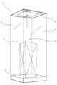
実施例に係る展示ケースにつき、図1から図5を参照して説明する。図1の符号1は、本発明の適用された展示ケースである。この展示ケース1は、主に美術館や博物館等に設置され、展示ケース1内に配置された展示品2を、鑑賞者が展示ケース1の周囲から鑑賞できるようになっている。 The display case according to the embodiment will be described with reference to FIGS.
図1に示すように、展示ケース1は、床面に設置されて平面視で略四角形状をなす展示台3を有し、展示台3の四方の各側面の外周を取り囲むように、床面から立設されたガラス等の材質で形成された透明な本発明における透明パネルとしての側面パネル4が4枚配置されている。この側面パネル4によって展示台3の上方に展示空間5が形成されている。そして、展示品2を展示台3の上面に配置でき、展示品2を展示空間5内に収容するようになっている。 As shown in FIG. 1, the
図2に示すように、各側面パネル4の上面開口部は、ガラス等の材質で形成された透明な上面パネル6で閉塞されており、この上面パネル6の上面側の中央部には、導光板ユニット7が配置されている。上面パネル6は、平面視で略四角形状をなし、導光板ユニット7も平面視で略四角形状をなし、かつこの導光板ユニット7は、上面パネル6よりも小さく形成されている(図4参照)。 As shown in FIG. 2, the upper surface opening of each
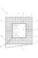
図3及び図4に示すように、導光板ユニット7の周辺部における上面パネル6の上面には、非透光性のカッティングシート8が接着剤等により貼り付けられている。このカッティングシート8により、上面パネル6における導光板ユニット7の周辺部が非透光となっている。尚、本実施例では、展示台3と側面パネル4と上面パネル6とによりケース本体が構成されている。 As shown in FIGS. 3 and 4, a
図3に示すように、導光板ユニット7は、アクリル樹脂等の材質で形成された導光板9を有している。この導光板9は、その上面の全面に渡って微細な凹凸が形成されている。この微細な凹凸は、シルク印刷加工やV溝カット加工や成形加工やレーザー加工等の所定の加工方法により形成されている。 As shown in FIG. 3, the light
導光板9の上面には、光を反射させる反射シート10が設けられている。導光板9の下面には、光を拡散させる拡散シート11が設けられている。平面視で略四角形状をなす導光板9の一辺側には、本発明における照明手段としての複数のLED12を有する照明基板13が設けられている。この照明基板13は、導光板9の端面に沿って延設されており、複数のLED12は、照明基板13の長手方向に沿って並設されており、このLED12は導光板9の端面側に向いている。 A
図3及び図4に示すように、照明基板13は、断面視で略コ字形状をなす枠部材14に装着されており、この枠部材14が導光板9の一辺側に設けられている。導光板9の照明基板13が設けられた一辺以外の三辺は、断面視で略コ字形状をなす枠部材14に嵌合されている。四つの枠部材14で囲まれた上面側は、カバー材15により閉塞されている。また、四つの枠部材14で囲まれた下面側は、開口されて下面開口部16が形成されている。 As shown in FIGS. 3 and 4, the
導光板ユニット7は、その枠部材14の下面側が接着剤等を用いてカッティングシート8の上面に接着されている。また、カッティングシート8は、導光板ユニット7の下面開口部16に対応した部位が切り取られており、導光板ユニット7の下面が露呈している。 In the light
図4に示すように、複数のLED12が導光板9の端面側にのみ配置されており、従来の一般的な照明装置のように、照射面全体にLEDを設けずにすむようになり、本実施例の導光板ユニット7は、その上下幅を小さくして薄型に形成し、かつ軽量化することができるとともに、LED12の使用個数を減らして製造コストを低減させることができる。また、薄型の導光板ユニット7を用いることにより、圧迫感が少ない展示ケース1とすることができる。 As shown in FIG. 4, the plurality of
照明基板13のLED12を点灯させると、LED12より発せられた光は、導光板9の端面に向かって入射される。この入射された光は、導光板9内部で広がり、導光板9の上面に達した光は、導光板9の上面に形成された微細な凹凸で拡散されつつ、反射シート10により反射され、導光板9の下面側に向かうようになっている。 When the
導光板9の下面に達した光は、拡散シート11により拡散され、導光板9の下面側全体から均一に照射されるようになっている。LED12から発せられる光は直接展示品2に照射されるのではなく導光板9を介して照射されるため、紫外線や赤外線を低減させた光を展示品2に照射させることができ、長時間照射しても、紫外線によって展示品2が色褪せたり、赤外線による熱で展示品2を傷めたりせずに済むようになる。 The light reaching the lower surface of the
前述したように、上面パネル6は、平面視で略四角形状をなし、導光板ユニット7も平面視で略四角形状をなし、かつこの導光板ユニット7は、上面パネル6よりも小さく形成されているが、導光板ユニット7から照射される光は、導光板ユニット7から外側斜め下方向に向かって広がるようになっており、この導光板ユニット7の大きさは、照射される光が展示台3の形状にまんべんなく照射される程度の大きさに形成されている。 As described above, the
そのため、展示台3よりも外方側に光が照射されないように、導光板ユニット7による照射領域を展示台3の上面に限定することにより導光板ユニット7の消費電力を低減できる。また、展示ケース1の外周に居る鑑賞者の目に光が直接入り込まないようにすることができる。 Therefore, the power consumption of the light
上面パネル6における導光板ユニット7の周辺部には、非透光性のカッティングシート8が貼られているため、展示ケース1の上方にある室内の天井の照明装置等から光が照射された際に、展示ケース1の上方から展示ケース1内に入り込む光が遮られることとなる。そのため、導光板ユニット7から発せられる光のみで展示品2を照らすことができ、展示ケース1による照明効果を高められる。 Since a
導光板ユニット7は、上面パネル6の上方に配置されているため、別途、導光板ユニット7を支持するための部材を用いることなく、上面パネルを利用して導光板ユニットを支持することができる。また、LED12から発生する熱によって暖められた空気が展示空間5内に入り込まないようになり、展示空間5内の温度上昇を防止することができる。 Since the light
尚、従来の一般的な照明装置のように、照射面全体にLEDを配置して照射されるようにすると、LEDは点発光するようになっているため、その点発光が目立ってしまい、照射面全体にLEDの光のムラができてしまうようになっている。しかしながら本実施例の導光板ユニット7では、LED12から照射された光が、一旦、導光板9に入射した後、拡散シート11を介して導光板ユニット7の下面側から照射されるようになっており、その照射面全体がムラなく一様に発光するようになっている。 In addition, when the LED is arranged and irradiated on the entire irradiation surface as in a conventional general lighting device, the LED emits a point light, so that the point light emission becomes conspicuous, and the irradiation is performed. The unevenness of the light of the LED is made on the entire surface. However, in the light
図4に示すように、側面パネル4のうち正面側の一枚は、その端縁に設けられたヒンジ17によって外方向に揺動されて開放される扉部となっている。この正面側の側面パネル4’を開放することで展示品2を展示空間5内に収容できるようになっている。更に、正面側の側面パネル4’を閉塞させる際に、この側面パネル4’の端縁が当接する戸当部18には、可撓性を有する合成樹脂等からなる戸当部材19が設けられている(図5参照)。 As shown in FIG. 4, one of the
また、LED12が配置される照明基板13から電力線20が導光板ユニット7の外部に延び、この電力線20は、導光板ユニット7の角部から上面パネル6の角部に向かって延びている。そして、この電力線20は、戸当部18に沿って下方側に延設されており、展示台3内部に配置された制御回路(図示略)に接続されている。この制御回路は、室内に設けられたコンセント等から電力を供給されるようになっている。 Further, the
更に、電力線20の配置についてより詳述すると、図5に示すように、戸当部材19は、その内部が空洞になっており、一方側が開いた形状となっている。そして、この戸当部材19の開いている側から戸当部材19の内側に、前述した電力線20を挿入して配線できるようになっている。そのため、電力線20が露呈しないように戸当部材19に保持させることができ、電力線20が展示品2の鑑賞を妨げないようになっている。 Further, the arrangement of the
図1及び図4に示すように、上面パネル6における導光板ユニット7の周辺部には、非透光性のカッティングシート8が貼り付けられているとともに、カッティングシート8の上面側に電力線20が配置されている。 As shown in FIGS. 1 and 4, a
そして、本実施例の展示ケース1は、一般的な鑑賞者の身長よりも大きく形成されており、鑑賞者が上面パネルを下方から見上げた際に、この電力線20はカッティングシート8により鑑賞者から見えないようになっている。更に、導光板ユニット7の枠部材14も、カッティングシート8の上面側に配置されているため、鑑賞者が上面パネルを下方から見上げた際に、枠部材14が鑑賞者から見えないようになっている。 The
尚、本実施例のような導光板ユニット7が上面パネル6に設置されている展示ケース1は、行灯型四面展示ケース1と称されている。また、本実施例の展示ケース1の上面パネル6から導光板ユニット7とカッティングシート8を取り外すと行灯型五面展示ケースとすることができる。すなわち、本実施例の行灯型四面展示ケース1は、その製造工程の途中の段階まで行灯型五面展示ケースの製造工程と同一になっている。 In addition, the
このように本実施例の行灯型四面展示ケース1は、行灯型五面展示ケースの製造工程を利用して、その行灯型五面展示ケースの上面パネル6に導光板ユニット7を配置して行灯型四面展示ケース1を製造することができるようになり、行灯型五面展示ケースと行灯型四面展示ケース1とを同じ製造工程で製造することができ、展示ケース1の生産効率を向上させることができる。更に、導光板ユニット7は、薄型に形成できるため、行灯型四面展示ケース1では、その上面パネル6の圧迫感がなくなり、行灯型五面展示ケースと行灯型四面展示ケース1との外観をほぼ同じように形成することができる。 As described above, the row lamp type four-sided
また、行灯型五面展示ケースを製造しておき、その後、この展示ケースを行灯型四面展示ケース1に改造する際には、カッティングシート8を上面パネル6の上面に貼り付け、その上面に導光板ユニット7を取り付けることで、容易に行灯型四面展示ケース1とすることができる。そして、この際に導光板ユニット7から延びる配線は、戸当部材19内部に配置できるため、導光板ユニット7の追加と同時に電力線20の配線作業が容易に行える。 In addition, when the row lamp type five-sided display case is manufactured and then the display case is modified to the row lamp type four-sided
以上、本発明の実施例を図面により説明してきたが、具体的な構成はこれら実施例に限られるものではなく、本発明の要旨を逸脱しない範囲における変更や追加があっても本発明に含まれる。 Although the embodiments of the present invention have been described with reference to the drawings, the specific configuration is not limited to these embodiments, and modifications and additions within the scope of the present invention are included in the present invention. It is.
例えば、前記実施例では、導光板ユニット7の照明手段としてLED12が用いられているが、本発明はこれに限ることなく、照明手段として冷陰極発光体(Cold Cathode Fluorescent Lamp、略称CCFL)を用いるようにしてもよい。 For example, in the above embodiment, the
また、前記実施例では、導光板9の一辺側にLED12を有する一つの照明基板13が設けられていたが、導光板9の一辺と対向する他方の辺とに二つの照明基板13を設けるようにしてもよいし、導光板9の四辺全てに四つの照明基板13を設けるようにして、複数の照明基板13によって一つの導光板9の内部に向かってLED12の光を照射させるようにしてもよい。 Moreover, in the said Example, although the one illumination board |
また、前記実施例では、上面パネル6における導光板ユニット7の周辺部を非透光性とするためカッティングシート8を貼り付けているが、例えば、上面パネル6における導光板ユニット7の下面開口部16に対応する位置のみが透明になるようにして、その他の部位に塗装を施したカラーガラスを上面パネル6に使用してもよい。 Moreover, in the said Example, although the
また、前記実施例では、上面パネル6における導光板ユニット7の周辺部を非透光性とするためカッティングシート8を貼り付けているが、上面パネル6にカッティングシートを貼り付けずに、上面パネル6の全面が透光性を有するようにしてもよい。 Moreover, in the said Example, although the
また、前記実施例では、ガラス等の材質で形成された透明な上面パネル6を使用したが、上面パネル6は必ずしも透明である必要はなく、くもりガラスのような材質を用いても、透光性を有するものであれば、いかなる材質を用いて上面パネル6を形成してもよい。 Moreover, in the said Example, although the transparent
また、前記実施例では、導光板ユニット7は上面パネル6の上方側に設置されているが、上面パネル6の下方側、つまりケース本体の内側に設置されていてもよい。 Moreover, in the said Example, although the light-
1 展示ケース
2 展示品
3 展示台
4 側面パネル(透明パネル)
4’ 側面パネル(扉部)
5 展示空間
6 上面パネル
7 導光板ユニット
9 導光板
12 LED(照明手段)
13 照明基板(照明手段)
18 戸当部
20 電力線1
4 'side panel (door)
5
13 Illumination board (illumination means)
18
Claims (5)
Translated fromJapanese前記上面パネルは、少なくとも一部が透光性を有し、該上面パネルには、導光板の端面側に設けた照明手段より発せられる光を、該導光板の端面に向かって入射させることにより、該導光板の下面側から光が照射されるようになっている導光板ユニットが配置されることを特徴とする展示ケース。An exhibition stand installed on the floor, and a case main body in which the periphery of the exhibition space formed above the exhibition stand is surrounded by a transparent panel, and the upper surface opening of each transparent panel is covered with the upper surface panel. In the display case provided,
At least a part of the upper panel is translucent, and light emitted from illumination means provided on the end face side of the light guide plate is incident on the upper panel toward the end face of the light guide plate. A display case in which a light guide plate unit adapted to emit light from the lower surface side of the light guide plate is disposed.
Priority Applications (1)
| Application Number | Priority Date | Filing Date | Title |
|---|---|---|---|
| JP2009166567AJP5501681B2 (en) | 2009-07-15 | 2009-07-15 | Display case |
Applications Claiming Priority (1)
| Application Number | Priority Date | Filing Date | Title |
|---|---|---|---|
| JP2009166567AJP5501681B2 (en) | 2009-07-15 | 2009-07-15 | Display case |
Publications (2)
| Publication Number | Publication Date |
|---|---|
| JP2011019682Atrue JP2011019682A (en) | 2011-02-03 |
| JP5501681B2 JP5501681B2 (en) | 2014-05-28 |
Family
ID=43630284
Family Applications (1)
| Application Number | Title | Priority Date | Filing Date |
|---|---|---|---|
| JP2009166567AActiveJP5501681B2 (en) | 2009-07-15 | 2009-07-15 | Display case |
Country Status (1)
| Country | Link |
|---|---|
| JP (1) | JP5501681B2 (en) |
Cited By (4)
| Publication number | Priority date | Publication date | Assignee | Title |
|---|---|---|---|---|
| JP2013094446A (en)* | 2011-11-01 | 2013-05-20 | Okamura Corp | Display case |
| JP2016052575A (en)* | 2015-11-26 | 2016-04-14 | 株式会社岡村製作所 | Display case |
| JP2019030488A (en)* | 2017-08-08 | 2019-02-28 | 株式会社大洋工芸 | Unit store fixture with lighting device |
| JP2022520464A (en)* | 2019-02-15 | 2022-03-30 | ユリウス ブルーム ゲー・エム・ベー・ハー | Furniture hinges |
Citations (6)
| Publication number | Priority date | Publication date | Assignee | Title |
|---|---|---|---|---|
| JPS6118058U (en)* | 1984-07-07 | 1986-02-01 | 伸彦 藤田 | decoration case |
| JPH01133450U (en)* | 1987-10-14 | 1989-09-11 | ||
| JPH05137623A (en)* | 1991-11-15 | 1993-06-01 | Matsushita Electric Works Ltd | Construction of cabinet with decorative illumination function |
| JPH0638117U (en)* | 1992-10-23 | 1994-05-20 | 松下電工株式会社 | Shelf with lighting equipment |
| JP3121700U (en)* | 2006-03-03 | 2006-05-25 | 株式会社山元 | Built-in lighting showcase |
| JP2009142445A (en)* | 2007-12-13 | 2009-07-02 | Itoki Corp | Display case |
- 2009
- 2009-07-15JPJP2009166567Apatent/JP5501681B2/enactiveActive
Patent Citations (6)
| Publication number | Priority date | Publication date | Assignee | Title |
|---|---|---|---|---|
| JPS6118058U (en)* | 1984-07-07 | 1986-02-01 | 伸彦 藤田 | decoration case |
| JPH01133450U (en)* | 1987-10-14 | 1989-09-11 | ||
| JPH05137623A (en)* | 1991-11-15 | 1993-06-01 | Matsushita Electric Works Ltd | Construction of cabinet with decorative illumination function |
| JPH0638117U (en)* | 1992-10-23 | 1994-05-20 | 松下電工株式会社 | Shelf with lighting equipment |
| JP3121700U (en)* | 2006-03-03 | 2006-05-25 | 株式会社山元 | Built-in lighting showcase |
| JP2009142445A (en)* | 2007-12-13 | 2009-07-02 | Itoki Corp | Display case |
Cited By (5)
| Publication number | Priority date | Publication date | Assignee | Title |
|---|---|---|---|---|
| JP2013094446A (en)* | 2011-11-01 | 2013-05-20 | Okamura Corp | Display case |
| JP2016052575A (en)* | 2015-11-26 | 2016-04-14 | 株式会社岡村製作所 | Display case |
| JP2019030488A (en)* | 2017-08-08 | 2019-02-28 | 株式会社大洋工芸 | Unit store fixture with lighting device |
| JP2022520464A (en)* | 2019-02-15 | 2022-03-30 | ユリウス ブルーム ゲー・エム・ベー・ハー | Furniture hinges |
| US11795745B2 (en) | 2019-02-15 | 2023-10-24 | Julius Blum Gmbh | Furniture hinge |
Also Published As
| Publication number | Publication date |
|---|---|
| JP5501681B2 (en) | 2014-05-28 |
Similar Documents
| Publication | Publication Date | Title |
|---|---|---|
| JP4290196B2 (en) | Planar light source and electric signboard | |
| US20130027927A1 (en) | Floating light luminaire | |
| US9297506B2 (en) | LED-based light fixture | |
| JP2012109207A (en) | Surface lighting body | |
| JP2011096506A (en) | Light guide panel for display, sign, and surface lighting | |
| US9395478B2 (en) | Blade of light luminaire | |
| JP5501681B2 (en) | Display case | |
| KR20090089783A (en) | Showcase | |
| EP2309170A1 (en) | Embedded lamp with auxiliary illumination | |
| JP3211553U (en) | Lighting device | |
| CN210441056U (en) | Energy-saving lamp illumination and disinfection device and energy-saving lamp | |
| CN202708988U (en) | Light guide plate (LGP) and lighting lamp | |
| JP5869841B2 (en) | Display case | |
| CN1959313B (en) | Partition rack set of refrigerator with illuminating apparatus | |
| US11624495B2 (en) | Systems and methods for stabilizing optical sheets in luminaires | |
| JP2017021916A (en) | Surface light-emitter | |
| JP5662172B2 (en) | Display case | |
| JP5662173B2 (en) | Display case | |
| JP2016052575A (en) | Display case | |
| JP5685447B2 (en) | Display case | |
| US20150354777A1 (en) | Decorative fixture | |
| JP2004302028A (en) | Display device and guide light device | |
| KR200498549Y1 (en) | Decorative cabinet with lighting shelf | |
| JP3205851U (en) | Lighting fixture | |
| JP5472866B2 (en) | Screen with light emitting function |
Legal Events
| Date | Code | Title | Description |
|---|---|---|---|
| A621 | Written request for application examination | Free format text:JAPANESE INTERMEDIATE CODE: A621 Effective date:20120709 | |
| A977 | Report on retrieval | Free format text:JAPANESE INTERMEDIATE CODE: A971007 Effective date:20130920 | |
| A131 | Notification of reasons for refusal | Free format text:JAPANESE INTERMEDIATE CODE: A131 Effective date:20131001 | |
| A521 | Request for written amendment filed | Free format text:JAPANESE INTERMEDIATE CODE: A523 Effective date:20131113 | |
| TRDD | Decision of grant or rejection written | ||
| A01 | Written decision to grant a patent or to grant a registration (utility model) | Free format text:JAPANESE INTERMEDIATE CODE: A01 Effective date:20140212 | |
| A61 | First payment of annual fees (during grant procedure) | Free format text:JAPANESE INTERMEDIATE CODE: A61 Effective date:20140312 | |
| R150 | Certificate of patent or registration of utility model | Ref document number:5501681 Country of ref document:JP Free format text:JAPANESE INTERMEDIATE CODE: R150 | |
| R250 | Receipt of annual fees | Free format text:JAPANESE INTERMEDIATE CODE: R250 | |
| R250 | Receipt of annual fees | Free format text:JAPANESE INTERMEDIATE CODE: R250 | |
| S533 | Written request for registration of change of name | Free format text:JAPANESE INTERMEDIATE CODE: R313533 | |
| R350 | Written notification of registration of transfer | Free format text:JAPANESE INTERMEDIATE CODE: R350 | |
| R250 | Receipt of annual fees | Free format text:JAPANESE INTERMEDIATE CODE: R250 | |
| R250 | Receipt of annual fees | Free format text:JAPANESE INTERMEDIATE CODE: R250 | |
| R250 | Receipt of annual fees | Free format text:JAPANESE INTERMEDIATE CODE: R250 | |
| R250 | Receipt of annual fees | Free format text:JAPANESE INTERMEDIATE CODE: R250 | |
| R250 | Receipt of annual fees | Free format text:JAPANESE INTERMEDIATE CODE: R250 | |
| R250 | Receipt of annual fees | Free format text:JAPANESE INTERMEDIATE CODE: R250 | |
| R250 | Receipt of annual fees | Free format text:JAPANESE INTERMEDIATE CODE: R250 |