JP2011013073A - Light emitting element luminous intensity compensation device in opacimeter - Google Patents
Light emitting element luminous intensity compensation device in opacimeterDownload PDFInfo
- Publication number
- JP2011013073A JP2011013073AJP2009156871AJP2009156871AJP2011013073AJP 2011013073 AJP2011013073 AJP 2011013073AJP 2009156871 AJP2009156871 AJP 2009156871AJP 2009156871 AJP2009156871 AJP 2009156871AJP 2011013073 AJP2011013073 AJP 2011013073A
- Authority
- JP
- Japan
- Prior art keywords
- light
- emitting element
- receiving element
- opacimeter
- compensation device
- Prior art date
- Legal status (The legal status is an assumption and is not a legal conclusion. Google has not performed a legal analysis and makes no representation as to the accuracy of the status listed.)
- Granted
Links
Images

Landscapes
- Investigating Or Analysing Materials By Optical Means (AREA)
Abstract
Description
Translated fromJapanese この発明はオパシメータ(透過式スモークメータ)における発光素子の発光光度補償装置に関するものである。
オパシメータは、測定室に導入された排ガスの粒状物質の濃度を光の減衰量で測定する装置である。The present invention relates to a luminous intensity compensation device for a light emitting element in an opacimeter (transmission type smoke meter).
The opacimeter is a device that measures the concentration of particulate matter in the exhaust gas introduced into the measurement chamber by the amount of attenuation of light.
オパシメータ101は図4に示すように、測定室3を挟んで向かい合った発光素子4と受光素子5により測定光路が形成され、測定室3内に被測定対象である排ガス21を導入し、その排ガス21中に発光素子4からの光を透過させて受光素子5で受光して計測し排ガス21内の粒状物質が光を吸収する量を検出し、減衰された光量から排ガスの光吸収係数(m−1)を算出する。排ガスの粒状物質が光を吸収した量を光吸収係数(K)と呼び、減衰光との関係はベア・ランベルト法則として広く知られている。
K=−(1/La)・{ln(I/I0)}(1式)ただし K :光吸収係数(1/m)
La :有効光路長さ(m)
I :排ガスがあるときの光量
I0 :排ガスが無いときの光量
I/I0 :排ガスの透過率
発光素子4の発光量は周囲温度に影響される場合がある。例えば発光素子4をLED(発光ダイオード)で構成した場合には、LEDの発光量はLEDの周囲温度が高くなると大きく減少し、温度が低くなると増加することは広く知られていて測定値の温度補償をする必要がある。As shown in FIG. 4, the
K = − (1 / La) · {ln (I / I0 )} (1 formula) where K: light absorption coefficient (1 / m)
La: Effective optical path length (m)
I: Light intensity when exhaust gas is present
I0 : Light quantity when there is no exhaust gas
I / I0 : Transmittance of exhaust gas The light emission amount of the
これまでの温度補償技術は、LED付近に感温素子を配置し、その温度測定値からLEDに流す電流を調整して発光量を一定にする手法、あるいは、温度測定値から受光側で受光量を補償する手法を用いている。
スモークメータにおいて、光吸収係数の温度補償を行う技術としては特許文献1及び2に記載されたものがある。Conventional temperature compensation technology is a method of arranging a temperature sensing element near the LED and adjusting the current flowing to the LED from the measured temperature value to make the emitted light amount constant, or the received light amount on the light receiving side from the measured temperature value Is used.
As a technique for performing temperature compensation of a light absorption coefficient in a smoke meter, there are those described in Patent Documents 1 and 2.
このうち、特許文献1に記載された技術は排ガス中の粒子状物質を吸着させてろ紙からの反射光を測定する反射式スモークメータに関する技術であるのでオパシメータ(透過型スモークメータ)とは測定原理が異なっている。 Among these, the technique described in Patent Document 1 is a technique related to a reflective smoke meter that adsorbs particulate matter in exhaust gas and measures the reflected light from the filter paper. Therefore, the opacimeter (transmission type smoke meter) is a measurement principle. Is different.
また特許文献2に記載された技術では排気管から排圧分流された排ガスは、オパシメータの測定室に導入され左右に分流され、測定室の左右の終端で掃気エアー(清浄空気)と合流させて大気に放出する。その間に発光素子のLEDから発せられた光は測定室内の排ガスを透過し、減衰して受光素子で受光され、減衰量から排ガスの光吸収係数が求められる。エアーカーテン14、15は掃気エアーを流して、受光素子、発光素子が排ガスの粒状物質、水分、等により汚染されるのを防ぐ役割を果たす。 Further, in the technique described in Patent Document 2, the exhaust gas divided by the exhaust pressure from the exhaust pipe is introduced into the measurement chamber of the opacimeter and divided into left and right, and merged with scavenging air (clean air) at the left and right ends of the measurement chamber. Release into the atmosphere. In the meantime, the light emitted from the LED of the light emitting element passes through the exhaust gas in the measurement chamber, attenuates and is received by the light receiving element, and the light absorption coefficient of the exhaust gas is obtained from the attenuation amount. The
このような、従来のオパシメータ101の問題点を次に示す。
(1)温度に対するLEDの発光量の特性は、個々に特有な特性を示す。よって個別の温
度特性を得る必要がある。
(2)感温素子のメモリ付けを必要とする。
(3)感温素子の熱容量と、LEDの熱容量が異なり、周囲温度が変化した場合に感温素
子とLEDの温度変化に違いができ、正しい補償値になるまで時間差が生じる。
(4)LEDの自己発熱により発光量変動を生じる。これは感温素子では検知できない。Such problems of the
(1) The characteristic of the light emission amount of the LED with respect to temperature shows a characteristic specific to each. Therefore, it is necessary to obtain individual temperature characteristics.
(2) A memory for the temperature sensitive element is required.
(3) The heat capacity of the temperature sensitive element and the heat capacity of the LED are different, and when the ambient temperature changes, the temperature change of the temperature sensitive element and the LED can be different, and a time difference occurs until the correct compensation value is obtained.
(4) The light emission amount fluctuates due to self-heating of the LED. This cannot be detected by the temperature sensitive element.
さらに感温素子によってLEDの周囲の温度を測定し、その温度測定値からLEDの発光量を補償したり、受光量を補正するためには、感温素子が必要となるだけでなく、LEDの発光量を求めるには間接的で、誤差が入り易い。 Furthermore, in order to measure the ambient temperature of the LED with the temperature sensing element and compensate the light emission amount of the LED from the temperature measurement value or to correct the light reception amount, not only the temperature sensing element is required, but also the LED It is indirect to determine the amount of light emission, and errors are likely to occur.
このようなことから、個々のLEDに個別の温度特性を得る必要がなく、感温素子を使用することなく迅速にLEDの発光量を補償することができ、温度変化に対応したLEDの発光量を直接に求めることができるオパシメータにおける発光素子光度補償技術の開発が望まれている。 For this reason, it is not necessary to obtain individual temperature characteristics for each LED, and the light emission amount of the LED can be quickly compensated without using a temperature sensing element, and the light emission amount of the LED corresponding to the temperature change. It is desired to develop a light-emitting element light intensity compensation technique in an opacimeter that can directly determine the light intensity.
この目的に対応してこの発明のオパシメータにおける発光素子光度補償装置は、被測定対象の排ガスを導入する測定室を通して測定用受光素子に達する測定用光路を形成する発光素子からの光を前記測定室内の排出ガスに透過させて前記測定用受光素子で受光するように構成したオパシメータにおける発光素子光度補償装置であって、前記発光素子からの発光を前記測定室を介さないで受け得る位置に参照用受光素子を配置したことを特徴としている。 Corresponding to this object, the light-emitting element luminous intensity compensation device in the opacimeter according to the present invention transmits light from a light-emitting element that forms a measurement optical path that reaches a light-receiving element for measurement through a measurement chamber that introduces exhaust gas to be measured. Is a light-emitting element light intensity compensation device in an opacimeter configured to be transmitted through an exhaust gas and received by the light-receiving element for measurement, and used as a reference at a position where light emitted from the light-emitting element can be received without passing through the measurement chamber It is characterized in that a light receiving element is arranged.
この発明のオパシメータにおける発光素子光度補償装置では、
(1)感温素子が不要になり、装置の構成を簡単にすることができる。
(2)また感温素子が無くなることで、温度に関連する調整が不要になり、迅速な測定が可能になる。
(3)また、LEDの発光光度の個々の温度特性取得作業が不要になり、測定操作が簡易になる。
(4)さらに温度変化に大変優れ、かつ低コストのオパシメータが構築できる。In the light emitting element luminous intensity compensation device in the opacimeter of the present invention,
(1) A temperature sensitive element is not required, and the configuration of the apparatus can be simplified.
(2) Further, since there is no temperature sensing element, adjustment related to temperature becomes unnecessary, and rapid measurement becomes possible.
(3) Moreover, the individual temperature characteristic acquisition work of the luminous intensity of the LED becomes unnecessary, and the measurement operation is simplified.
(4) Furthermore, it is possible to construct an opacimeter that is extremely excellent in temperature change and low in cost.
以下この発明の詳細を実施の形態を示す図面について説明する。
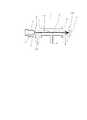
図1及び図2において、1はオパシメータである。オパシメータ1は発光素子発光度補償装置(以下単に「補償装置」と称する)2を備えている。
補償装置2は測定室3と発光素子4と受光素子5とを備えている。
測定室3は排ガスを収容可能な空間をなし、その中間部に被測定対象である排ガスを導入する排ガス入り口6とその両端に排ガスを排出する排ガス出口7、8とが開口している。
排ガス出口7、8にはエアーカーテン部14、15が設けられ、エアーカーテン部14、15には掃気エアーが流出され、排ガス出口7、8における排ガスの流出を案内して排ガスが後述する発光素子4や受光素子5に接触するのを阻止する。The details of the present invention will be described below with reference to the drawings showing embodiments.
1 and 2, reference numeral 1 denotes an opacimeter. The opacimeter 1 includes a light emitting element luminous intensity compensation device (hereinafter simply referred to as “compensation device”) 2.
The compensation device 2 includes a measurement chamber 3, a
The measurement chamber 3 has a space in which exhaust gas can be accommodated, and an exhaust gas inlet 6 for introducing the exhaust gas to be measured is opened at an intermediate portion thereof, and exhaust gas outlets 7 and 8 for discharging the exhaust gas are opened at both ends thereof.
一方の排ガス出口7に対向して発光素子4が配置されていて、発光素子4は測定室3を貫通して、排ガス出口7から排ガス出口8に達する光路11に光を投射することが可能である。発光素子4としてはLEDやランプで構成することができる。 The light-emitting
排ガス出口8に対向して光路11上に受光素子5が配置されている。受光素子5はフォトダイオード等で構成されている。 The light receiving
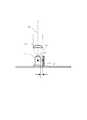
発光素子4の近傍に補償装置2が設けられている。補償装置2は参照用受光装置12を備えている。
参照用受光素子12の目的は、周囲温度の変化、およびLED等の発光素子4の自己発熱によるLED光量変化を検出することである。
発光素子4の光路11に向う光と参照用受光素子12に向う光との光量比が定まっているもので、かつ参照用受光素子12は受光素子5と温度特性が同じもので構成し、また参照用受光素子12と受光素子5の設置位置は同じ温度環境で設置する。A compensation device 2 is provided in the vicinity of the
The purpose of the reference
The light quantity ratio between the light directed to the
また参照用受光素子12の設置位置は発光素子4からの光が受けられる位置で、かつ発光素子4からの受光量に影響を与えるような実質的な熱量の伝達がない位置であることが必要である。 The
さらに参照用受光素子12の設置位置は発光素子4の光路11と干渉しない位置である必要がある。
このような発光素子4、受光素子5、参照用受光素子12の条件を満たすために、受光素子5と参照用受光素子12は一例として
発光素子4はLEDで構成し、受光素子5、参照用受光素子12は共にフォトダイオードで構成し、かつ参照用受光素子12の設置位置は、受光面13が光路11と平行で発光素子4の側面16からXmm(Xmm=0.2〜0.5mm)離れた位置にする。
受光素子5と参照用受光素子12との2つの受光素子は温度依存性が少ないもの、あるいは温度に対する受光素子が同じ特性のものを採用する。Furthermore, the reference
In order to satisfy the conditions of the
As the two light receiving elements, the
参照用受光素子12は、LEDの自己加熱の影響を受けず、かつ、受光量が不足しない距離で図2のようにLEDの側面近傍に配置する。 The reference
参照用受光素子12の測定値は、LEDの自己加熱と周囲温度の影響で変化した光量が検出でき、排ガスに含まれる粒状物質による減衰には影響されない。 The measured value of the reference
このように構成されたオパシメータ1における発光度補償つき排ガスの粒状物質の濃度測定は次のようにして行う。
被測定対象である排ガスはエンジンの排気管から排圧によって排ガス入口6から測定室3に入り左右に分かれて測定室3内に充満し、濃度計測され、その後、測定室3の両端の排ガス出口7、8からエアーカーテン14、15の掃気空気流に案内されて外部に排出されている。In the thus configured opacimeter 1, the concentration measurement of the particulate matter in the exhaust gas with luminosity compensation is performed as follows.
Exhaust gas to be measured enters the measurement chamber 3 through the exhaust gas inlet 6 by exhaust pressure from the exhaust pipe of the engine, is divided into left and right, fills the measurement chamber 3, measures the concentration, and then exhaust gas outlets at both ends of the measurement chamber 3. 7 and 8 are guided by the scavenging air flow of the
光吸収係数の計測においては、発光素子4が発光した発光の主要部分はコンデンサーレンズ17を通して、光路11に従って測定室3を通り、その間に測定室3内の排ガスの粒状物質によって減衰されて受光素子5に達し、受光量の計測がなされる。 In the measurement of the light absorption coefficient, the main part of the light emitted by the
一方、発光素子4の発光の一定割合は排ガスに減衰されない状態で参照用受光素子12に達する。 On the other hand, a certain proportion of the light emitted from the
発光素子4の周囲温度が変動した場合、発光素子4の光量変動は受光素子12と同じ割合で変動する。 When the ambient temperature of the
一般に透過率(T)はT=(IS/IS0)×100(2式)と表される。
T :粒状物質の透過率(%)
IS :粒状物質が存在するときの受光素子5の受光量
IS0:粒状物質が存在しないときの受光素子5の受光量
受光素子Rを利用して温度補償をした透過率は、
T=(IS/IS0)・(IR0/IR)×100(3式)となる。
T :粒状物質の透過率(%)
IS :粒状物質が存在するときの受光素子5の受光量
IS0:粒状物質が存在しないときの受光素子5の受光量
IR :粒状物質が存在するときの受光素子12の受光量
IR0 : 粒状物質が存在しないときの受光素子12の受光量
周囲温度の影響によりLED発光量が変動した場合のそれぞれの受光量は同じ割合で影響を受ける。温度による変動分をaとすると、ISとIRはそれぞれ
IS→a・IS
IR→a・IR
となる。Generally, the transmittance (T) is expressed as T = (IS / IS0 ) × 100 (2 formulas).
T: Permeability of particulate matter (%)
IS: amount of light received by the
T = (IS / IS0 ) · (IR0 / IR ) × 100 (3 formulas).
T: Permeability of particulate matter (%)
IS : Amount of light received by the
IR → a ・ IR
It becomes.
これを3式に代入すると
T={(a・IS)/IS0}・{IR0/(a・IR)}×100(4式)
となり、温度変動による光量変動分は相殺される。
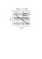
こうして図3に示すように、周囲温度の変動に対して透過率の測定値が良好に補償される。
以上の説明から明らかなように、本発明による補償検出器付オパシメータ1によって、測定中の温度変化および光源の光量変化の影響は完全に補償できる。図3には従来の測定方式の検出器の場合の周囲温度の影響の測定例に対比して、本発明の補償検出器付の場合の周囲温度の影響の実測例が示してある。このように、5℃〜45℃と大きく周囲温度が変化しても測定値には全く影響しない。また、一般には光源は時間と共に光量が変化するが、本発明の補償検出器によってはこの光源光量の変化も十分に補償して測定できる。さらに、測定出力信号は通常のアナログ計測器においては3桁程度の分解能しか得られないが、本発明による演算処理によって4桁以上の精度と読み取りが可能となる。これらの効果によって、ディーゼル排気の黒煙濃度の測定において従来の方式よりも1桁低い濃度まで高精度と高分解能で測定できる。Substituting this into Equation 3, T = {(a · IS ) / IS0 } · {IR0 / (a · IR )} × 100 (Equation 4)
Thus, the light quantity fluctuation due to temperature fluctuation is canceled out.
Thus, as shown in FIG. 3, the measured transmittance value is well compensated for variations in ambient temperature.
As is clear from the above description, the effect of the temperature change during measurement and the light quantity change of the light source can be completely compensated by the opacimeter 1 with a compensation detector according to the present invention. FIG. 3 shows an actual measurement example of the influence of the ambient temperature in the case with the compensation detector of the present invention, in contrast to the measurement example of the influence of the ambient temperature in the case of the detector of the conventional measurement method. In this way, even if the ambient temperature changes greatly as 5 ° C. to 45 ° C., the measured value is not affected at all. In general, the light amount of the light source changes with time. However, depending on the compensation detector of the present invention, the change in the light source amount can be sufficiently compensated for and measured. Furthermore, the measurement output signal can only have a resolution of about 3 digits in a normal analog measuring instrument, but the arithmetic processing according to the present invention makes it possible to read and read with an accuracy of 4 digits or more. Due to these effects, the black smoke concentration of diesel exhaust can be measured with high accuracy and high resolution down to an order of magnitude lower than the conventional method.
1 オパシメータ
2 発光素子発光度補償装置
3 測定室
4 発光素子
5 受光素子
6 排ガス入口
7 排ガス出口
8 排ガス出口
11 光路
12 参照用受光素子
14 エアーカーテン部
15 エアーカーテン部
16 発光素子の側面
17 コンデンサーレンズ
21 排ガス
101 オパシメータDESCRIPTION OF SYMBOLS 1 Opacimeter 2 Light emitting element luminous intensity compensation apparatus 3
Claims (8)
Translated fromJapanesePriority Applications (1)
| Application Number | Priority Date | Filing Date | Title |
|---|---|---|---|
| JP2009156871AJP5804619B2 (en) | 2009-07-01 | 2009-07-01 | Light-emitting element luminous intensity compensation device in opacimeter |
Applications Claiming Priority (1)
| Application Number | Priority Date | Filing Date | Title |
|---|---|---|---|
| JP2009156871AJP5804619B2 (en) | 2009-07-01 | 2009-07-01 | Light-emitting element luminous intensity compensation device in opacimeter |
Publications (2)
| Publication Number | Publication Date |
|---|---|
| JP2011013073Atrue JP2011013073A (en) | 2011-01-20 |
| JP5804619B2 JP5804619B2 (en) | 2015-11-04 |
Family
ID=43592133
Family Applications (1)
| Application Number | Title | Priority Date | Filing Date |
|---|---|---|---|
| JP2009156871AActiveJP5804619B2 (en) | 2009-07-01 | 2009-07-01 | Light-emitting element luminous intensity compensation device in opacimeter |
Country Status (1)
| Country | Link |
|---|---|
| JP (1) | JP5804619B2 (en) |
Cited By (4)
| Publication number | Priority date | Publication date | Assignee | Title |
|---|---|---|---|---|
| WO2016174762A1 (en)* | 2015-04-30 | 2016-11-03 | 富士電機株式会社 | Laser-type gas analyzer |
| WO2016174759A1 (en)* | 2015-04-30 | 2016-11-03 | 富士電機株式会社 | Laser-type gas analyzer |
| WO2016174761A1 (en)* | 2015-04-30 | 2016-11-03 | 富士電機株式会社 | Laser-type gas analyzer for ships |
| JP2019009390A (en)* | 2017-06-28 | 2019-01-17 | パナソニックIpマネジメント株式会社 | Light emitting apparatus and optical analysis system including the same |
Citations (7)
| Publication number | Priority date | Publication date | Assignee | Title |
|---|---|---|---|---|
| JPS63124935A (en)* | 1986-11-14 | 1988-05-28 | Hochiki Corp | Dimming type smoke sensor |
| JPH01107956U (en)* | 1988-01-12 | 1989-07-20 | ||
| JPH041438A (en)* | 1990-04-17 | 1992-01-06 | Hitachi Ltd | Internal combustion engine control device |
| JPH04177148A (en)* | 1990-11-09 | 1992-06-24 | Tatsuta Electric Wire & Cable Co Ltd | State sensor of liquid |
| JP2003232731A (en)* | 2002-02-06 | 2003-08-22 | Horiba Ltd | Smoke measuring system |
| JP2008256663A (en)* | 2007-04-09 | 2008-10-23 | Nippon Soken Inc | Urea concentration detector |
| JP2009014585A (en)* | 2007-07-06 | 2009-01-22 | Riken Keiki Co Ltd | Opacimeter |
- 2009
- 2009-07-01JPJP2009156871Apatent/JP5804619B2/enactiveActive
Patent Citations (7)
| Publication number | Priority date | Publication date | Assignee | Title |
|---|---|---|---|---|
| JPS63124935A (en)* | 1986-11-14 | 1988-05-28 | Hochiki Corp | Dimming type smoke sensor |
| JPH01107956U (en)* | 1988-01-12 | 1989-07-20 | ||
| JPH041438A (en)* | 1990-04-17 | 1992-01-06 | Hitachi Ltd | Internal combustion engine control device |
| JPH04177148A (en)* | 1990-11-09 | 1992-06-24 | Tatsuta Electric Wire & Cable Co Ltd | State sensor of liquid |
| JP2003232731A (en)* | 2002-02-06 | 2003-08-22 | Horiba Ltd | Smoke measuring system |
| JP2008256663A (en)* | 2007-04-09 | 2008-10-23 | Nippon Soken Inc | Urea concentration detector |
| JP2009014585A (en)* | 2007-07-06 | 2009-01-22 | Riken Keiki Co Ltd | Opacimeter |
Cited By (5)
| Publication number | Priority date | Publication date | Assignee | Title |
|---|---|---|---|---|
| WO2016174762A1 (en)* | 2015-04-30 | 2016-11-03 | 富士電機株式会社 | Laser-type gas analyzer |
| WO2016174759A1 (en)* | 2015-04-30 | 2016-11-03 | 富士電機株式会社 | Laser-type gas analyzer |
| WO2016174761A1 (en)* | 2015-04-30 | 2016-11-03 | 富士電機株式会社 | Laser-type gas analyzer for ships |
| JPWO2016174761A1 (en)* | 2015-04-30 | 2017-06-22 | 富士電機株式会社 | Marine Laser Gas Analyzer |
| JP2019009390A (en)* | 2017-06-28 | 2019-01-17 | パナソニックIpマネジメント株式会社 | Light emitting apparatus and optical analysis system including the same |
Also Published As
| Publication number | Publication date |
|---|---|
| JP5804619B2 (en) | 2015-11-04 |
Similar Documents
| Publication | Publication Date | Title |
|---|---|---|
| KR102122840B1 (en) | Spectroscopic analysis method and spectroscopic analyzer | |
| JP6360430B2 (en) | Sensor apparatus and method based on wavelength center detection | |
| WO2007120898A3 (en) | Carbon monoxide (co) microsir sensor system | |
| KR102027264B1 (en) | Concentration measuring device | |
| JP6651126B2 (en) | Gas analyzer | |
| JP5804619B2 (en) | Light-emitting element luminous intensity compensation device in opacimeter | |
| TWI736118B (en) | Concentration measuring device | |
| CN105358964A (en) | Photochemical Analyzer and Liquid Depth Sensor | |
| JPH04505967A (en) | Device for measuring the composition of fluids, e.g. components of exhaust gas from internal combustion engines | |
| JP2013096889A (en) | Infrared gas analyzer | |
| KR102561924B1 (en) | Concentration measurement device | |
| JPWO2020066769A5 (en) | ||
| KR100910871B1 (en) | Real-time moisture measurement method and device for chimney without CO2 interference | |
| KR101346439B1 (en) | Gas sensor utilizing bandpass filters to measure temperature of an emitter | |
| GB2495703A (en) | Optical sensor without wavelength filter | |
| KR101960226B1 (en) | Apparatus for measuring black carbon | |
| JP2016136122A (en) | Dissolved substance concentration measuring device in liquid | |
| CN207937352U (en) | A sensitive probe and non-spectral infrared gas sensor detection system | |
| CN109655406A (en) | Spectral water quality detection device and detection method | |
| JP2009139135A (en) | Infrared absorption gas analyzer | |
| CN108169140A (en) | For determining measured method relevant with delustring and corresponding sensor device | |
| JPS58156837A (en) | Measuring device for optical gas analysis | |
| RU63067U1 (en) | OPTICAL-ELECTRONIC DEVICE FOR MEASURING SOLID PARTICLE CONCENTRATION IN SMOKE GASES | |
| JP2022017606A (en) | Concentration sensor | |
| KR100900184B1 (en) | Light transmission soot measuring device |
Legal Events
| Date | Code | Title | Description |
|---|---|---|---|
| A621 | Written request for application examination | Free format text:JAPANESE INTERMEDIATE CODE: A621 Effective date:20120629 | |
| A977 | Report on retrieval | Free format text:JAPANESE INTERMEDIATE CODE: A971007 Effective date:20130531 | |
| A131 | Notification of reasons for refusal | Free format text:JAPANESE INTERMEDIATE CODE: A131 Effective date:20130604 | |
| A521 | Request for written amendment filed | Free format text:JAPANESE INTERMEDIATE CODE: A523 Effective date:20130805 | |
| A02 | Decision of refusal | Free format text:JAPANESE INTERMEDIATE CODE: A02 Effective date:20140331 | |
| A521 | Request for written amendment filed | Free format text:JAPANESE INTERMEDIATE CODE: A821 Effective date:20140630 | |
| A521 | Request for written amendment filed | Free format text:JAPANESE INTERMEDIATE CODE: A523 Effective date:20150805 | |
| A61 | First payment of annual fees (during grant procedure) | Free format text:JAPANESE INTERMEDIATE CODE: A61 Effective date:20150831 | |
| R150 | Certificate of patent or registration of utility model | Ref document number:5804619 Country of ref document:JP Free format text:JAPANESE INTERMEDIATE CODE: R150 | |
| R250 | Receipt of annual fees | Free format text:JAPANESE INTERMEDIATE CODE: R250 | |
| R250 | Receipt of annual fees | Free format text:JAPANESE INTERMEDIATE CODE: R250 | |
| R250 | Receipt of annual fees | Free format text:JAPANESE INTERMEDIATE CODE: R250 | |
| R250 | Receipt of annual fees | Free format text:JAPANESE INTERMEDIATE CODE: R250 | |
| R250 | Receipt of annual fees | Free format text:JAPANESE INTERMEDIATE CODE: R250 | |
| R250 | Receipt of annual fees | Free format text:JAPANESE INTERMEDIATE CODE: R250 | |
| R250 | Receipt of annual fees | Free format text:JAPANESE INTERMEDIATE CODE: R250 | |
| R250 | Receipt of annual fees | Free format text:JAPANESE INTERMEDIATE CODE: R250 |