JP2011008255A - Display device, method of display and recording medium for the method - Google Patents
Display device, method of display and recording medium for the methodDownload PDFInfo
- Publication number
- JP2011008255A JP2011008255AJP2010141139AJP2010141139AJP2011008255AJP 2011008255 AJP2011008255 AJP 2011008255AJP 2010141139 AJP2010141139 AJP 2010141139AJP 2010141139 AJP2010141139 AJP 2010141139AJP 2011008255 AJP2011008255 AJP 2011008255A
- Authority
- JP
- Japan
- Prior art keywords
- display
- screen
- screens
- display device
- display surface
- Prior art date
- Legal status (The legal status is an assumption and is not a legal conclusion. Google has not performed a legal analysis and makes no representation as to the accuracy of the status listed.)
- Granted
Links
Images


Classifications
- G—PHYSICS
- G06—COMPUTING OR CALCULATING; COUNTING
- G06F—ELECTRIC DIGITAL DATA PROCESSING
- G06F3/00—Input arrangements for transferring data to be processed into a form capable of being handled by the computer; Output arrangements for transferring data from processing unit to output unit, e.g. interface arrangements
- G06F3/14—Digital output to display device ; Cooperation and interconnection of the display device with other functional units
- G06F3/1423—Digital output to display device ; Cooperation and interconnection of the display device with other functional units controlling a plurality of local displays, e.g. CRT and flat panel display
- G06F3/1446—Digital output to display device ; Cooperation and interconnection of the display device with other functional units controlling a plurality of local displays, e.g. CRT and flat panel display display composed of modules, e.g. video walls
- G—PHYSICS
- G06—COMPUTING OR CALCULATING; COUNTING
- G06F—ELECTRIC DIGITAL DATA PROCESSING
- G06F3/00—Input arrangements for transferring data to be processed into a form capable of being handled by the computer; Output arrangements for transferring data from processing unit to output unit, e.g. interface arrangements
- G06F3/14—Digital output to display device ; Cooperation and interconnection of the display device with other functional units
- G—PHYSICS
- G06—COMPUTING OR CALCULATING; COUNTING
- G06F—ELECTRIC DIGITAL DATA PROCESSING
- G06F13/00—Interconnection of, or transfer of information or other signals between, memories, input/output devices or central processing units
- G06F13/10—Program control for peripheral devices
- G—PHYSICS
- G06—COMPUTING OR CALCULATING; COUNTING
- G06F—ELECTRIC DIGITAL DATA PROCESSING
- G06F3/00—Input arrangements for transferring data to be processed into a form capable of being handled by the computer; Output arrangements for transferring data from processing unit to output unit, e.g. interface arrangements
- G06F3/14—Digital output to display device ; Cooperation and interconnection of the display device with other functional units
- G06F3/1415—Digital output to display device ; Cooperation and interconnection of the display device with other functional units with means for detecting differences between the image stored in the host and the images displayed on the displays
- G—PHYSICS
- G09—EDUCATION; CRYPTOGRAPHY; DISPLAY; ADVERTISING; SEALS
- G09G—ARRANGEMENTS OR CIRCUITS FOR CONTROL OF INDICATING DEVICES USING STATIC MEANS TO PRESENT VARIABLE INFORMATION
- G09G3/00—Control arrangements or circuits, of interest only in connection with visual indicators other than cathode-ray tubes
- G09G3/20—Control arrangements or circuits, of interest only in connection with visual indicators other than cathode-ray tubes for presentation of an assembly of a number of characters, e.g. a page, by composing the assembly by combination of individual elements arranged in a matrix no fixed position being assigned to or needed to be assigned to the individual characters or partial characters
- G09G3/2092—Details of a display terminals using a flat panel, the details relating to the control arrangement of the display terminal and to the interfaces thereto
- G—PHYSICS
- G09—EDUCATION; CRYPTOGRAPHY; DISPLAY; ADVERTISING; SEALS
- G09G—ARRANGEMENTS OR CIRCUITS FOR CONTROL OF INDICATING DEVICES USING STATIC MEANS TO PRESENT VARIABLE INFORMATION
- G09G2320/00—Control of display operating conditions
- G09G2320/06—Adjustment of display parameters
- G09G2320/0693—Calibration of display systems
- G—PHYSICS
- G09—EDUCATION; CRYPTOGRAPHY; DISPLAY; ADVERTISING; SEALS
- G09G—ARRANGEMENTS OR CIRCUITS FOR CONTROL OF INDICATING DEVICES USING STATIC MEANS TO PRESENT VARIABLE INFORMATION
- G09G2320/00—Control of display operating conditions
- G09G2320/08—Arrangements within a display terminal for setting, manually or automatically, display parameters of the display terminal
- G—PHYSICS
- G09—EDUCATION; CRYPTOGRAPHY; DISPLAY; ADVERTISING; SEALS
- G09G—ARRANGEMENTS OR CIRCUITS FOR CONTROL OF INDICATING DEVICES USING STATIC MEANS TO PRESENT VARIABLE INFORMATION
- G09G2340/00—Aspects of display data processing
- G09G2340/04—Changes in size, position or resolution of an image
- G09G2340/0407—Resolution change, inclusive of the use of different resolutions for different screen areas
- G09G2340/0414—Vertical resolution change
- G—PHYSICS
- G09—EDUCATION; CRYPTOGRAPHY; DISPLAY; ADVERTISING; SEALS
- G09G—ARRANGEMENTS OR CIRCUITS FOR CONTROL OF INDICATING DEVICES USING STATIC MEANS TO PRESENT VARIABLE INFORMATION
- G09G2340/00—Aspects of display data processing
- G09G2340/04—Changes in size, position or resolution of an image
- G09G2340/0407—Resolution change, inclusive of the use of different resolutions for different screen areas
- G09G2340/0421—Horizontal resolution change
- G—PHYSICS
- G09—EDUCATION; CRYPTOGRAPHY; DISPLAY; ADVERTISING; SEALS
- G09G—ARRANGEMENTS OR CIRCUITS FOR CONTROL OF INDICATING DEVICES USING STATIC MEANS TO PRESENT VARIABLE INFORMATION
- G09G2340/00—Aspects of display data processing
- G09G2340/04—Changes in size, position or resolution of an image
- G09G2340/0464—Positioning
- G09G2340/0471—Vertical positioning
- G—PHYSICS
- G09—EDUCATION; CRYPTOGRAPHY; DISPLAY; ADVERTISING; SEALS
- G09G—ARRANGEMENTS OR CIRCUITS FOR CONTROL OF INDICATING DEVICES USING STATIC MEANS TO PRESENT VARIABLE INFORMATION
- G09G2340/00—Aspects of display data processing
- G09G2340/04—Changes in size, position or resolution of an image
- G09G2340/0464—Positioning
- G09G2340/0478—Horizontal positioning
Landscapes
- Engineering & Computer Science (AREA)
- Theoretical Computer Science (AREA)
- Physics & Mathematics (AREA)
- General Physics & Mathematics (AREA)
- General Engineering & Computer Science (AREA)
- Human Computer Interaction (AREA)
- Computer Hardware Design (AREA)
- Multimedia (AREA)
- Devices For Indicating Variable Information By Combining Individual Elements (AREA)
- Control Of Indicators Other Than Cathode Ray Tubes (AREA)
- Controls And Circuits For Display Device (AREA)
- Overhead Projectors And Projection Screens (AREA)
Abstract
Translated fromJapaneseDescription
Translated fromJapanese本発明は、表示装置、およびこの表示装置による表示方法に関する。本発明は、さらに、この表示方法を遂行するための情報記録媒体に関する。 The present invention relates to a display device and a display method using the display device. The present invention further relates to an information recording medium for performing this display method.
現在、ファイリングの関係者には、次のものを備えている表示装置は公知である。
− 同一の表示平面に平行に配置された複数のスクリーンであって、各スクリーンの個別表示面の総計から、個別表示面間で重なり合っている部分の面(それがあるとすれば)を引いた面と等しい画像の統合表示面を形成している複数のスクリーンと、
− 統合表示面の全面にわたって全体画像を表示するように、各スクリーンの上における部分画像の表示を制御することができるコンピュータ。At present, display devices including the following are well known to those involved in filing.
-Multiple screens arranged in parallel on the same display plane, subtracting the surface of the individual display surfaces of each screen (if any) that overlap between the individual display surfaces A plurality of screens forming an integrated display surface of an image equal to the surface;
A computer capable of controlling the display of partial images on each screen so as to display the entire image over the entire integrated display surface;
公知のこのような表示装置においては、スクリーンは、なんらの自由度もないようにして、相互に固定されている。より詳細に述べると、スクリーンは、個別の表示面が重なり合わないように、互いに隣接して位置している。 In such known display devices, the screens are fixed to each other without any degree of freedom. More specifically, the screens are located adjacent to each other so that the individual display surfaces do not overlap.
これらの表示装置は、いくつかの個別表示面を用いて、大きな総表示面を得るために利用される。しかしながら、このような表示装置は非常にかさばる。したがって、このような表示装置を携帯端末に用いることは非常に難しい。 These display devices are used to obtain a large total display surface using several individual display surfaces. However, such a display device is very bulky. Therefore, it is very difficult to use such a display device for a portable terminal.
本発明は、従来技術のこのような欠点を克服することを目的としている。 The present invention aims to overcome these disadvantages of the prior art.
この目的を達成するために、本発明は、次のような表示装置を提供するものである。
− スクリーンは、統合表示面を縮小するために、スクリーンのうちの少なくとも2つが重なり合っている引っ込み位置と、統合表示面を増加させるために、スクリーンの重なり合いが軽減または解除されている完全展開位置との間で、表示平面と平行に変位することができ、
− コンピュータは、引っ込み位置と完全展開位置との両方において、統合表示面の全面にわたって、全体画像を表示するように制御することができる。In order to achieve this object, the present invention provides the following display device.
The screen has a retracted position where at least two of the screens overlap to reduce the integrated display surface, and a fully unfolded position where the screen overlap is reduced or released to increase the integrated display surface; Can be displaced parallel to the display plane,
-The computer can be controlled to display the entire image over the entire integrated display surface in both the retracted position and the fully deployed position.
引っ込み位置へのスクリーンの変位が可能であることによって、表示装置の要求空間は縮小される。これは、引っ込み位置への表示装置の変位の際に有用である。 By allowing the screen to be moved to the retracted position, the required space of the display device is reduced. This is useful when the display device is displaced to the retracted position.
逆に、展開位置へのスクリーンの変位が可能であるため、表示装置の使用中、より大きな統合表示面を得ることができる。 Conversely, since the screen can be displaced to the unfolded position, a larger integrated display surface can be obtained during use of the display device.
この表示装置の実施形態においては、次の特性のうちの1つ以上を備えていてもよい。
・ この表示装置は、スクリーンの位置を測定することができる少なくとも1つのセンサ、および測定されたスクリーンの位置に、画像の表示を自動的に適合させることができるコンピュータを備えている。
・ コンピュータは、引っ込み位置と完全展開位置との両方において、統合表示面の全面にわたって、同一の全体画像を表示するように制御することができる。
・ 表示装置は、互いに相対的に変位することができる、少なくとも3つのスクリーン、およびそれらのスクリーンの変位の間に相関を与えることができる同期メカニズムを備えている。
・ 表示装置は、引っ込み位置と完全展開位置との中間の少なくとも1つの中間位置に、スクリーンの位置をロックするためのメカニズムを備えている。This embodiment of the display device may have one or more of the following characteristics.
The display device comprises at least one sensor capable of measuring the position of the screen and a computer capable of automatically adapting the display of the image to the measured position of the screen;
The computer can be controlled to display the same entire image over the entire integrated display surface in both the retracted position and the fully expanded position.
The display device comprises at least three screens that can be displaced relative to each other and a synchronization mechanism that can provide a correlation between the displacements of the screens.
The display device comprises a mechanism for locking the position of the screen in at least one intermediate position between the retracted position and the fully deployed position;
さらに、表示装置のこれらの実施形態は、次の長所を有している。
− スクリーンの位置を検出するためのセンサを用いることによって、画像の表示をスクリーンの位置に自動的に適合させることができ、したがって、この表示装置の使用方法が簡単になる。
− 可変サイズの統合表示面の全面にわたって、同一の画像を表示することにより、統合表示面を拡大して、画像のサイズを拡大する新しい方法が、ユーザに提供される。
− 同期メカニズムを用いることによって、例えば統合表示面の幅と高さの比を、あらかじめ定められた値とすることができる。
− 中間位置をロックするためのメカニズムを用いることによって、統合表示面を、ユーザの希望に、より容易に適合させることができる。Furthermore, these embodiments of the display device have the following advantages.
-By using a sensor for detecting the position of the screen, the display of the image can be automatically adapted to the position of the screen, thus simplifying the use of this display device.
A new way to enlarge the size of the image by displaying the same image over the entire variable size integrated display surface, providing the user with a new method.
-By using a synchronization mechanism, for example, the ratio of the width and height of the integrated display surface can be set to a predetermined value.
-By using a mechanism for locking the intermediate position, the integrated display surface can be more easily adapted to the user's wishes.
本発明は、さらに、上述の表示装置上に画像を表示するための、次のステップを含む方法を提供するものである。
− 引っ込み位置と完全展開位置との両方において、統合表示面の全面にわたって、全体画像を表示するように制御するステップ。The present invention further provides a method for displaying an image on the above-described display device, including the following steps.
-Controlling to display the entire image over the whole of the integrated display surface in both the retracted position and the fully unfolded position.
この表示の方法の実施形態は、次の特性を備えていてもよい。
・ この方法は、次のステップを含んでいる。
− スクリーンの位置を測定するステップと、
− 測定されたスクリーンの位置から、スクリーンの変位を検出するステップと、
− それに応じて、各部分画像を表示するための新しい制御を自動的に開始するステップ。
・ この方法は、引っ込み位置と完全展開位置との両方において、統合表示面の全面にわたって、同一の全体画像を表示するように制御するステップを含んでいる。This embodiment of the display method may have the following characteristics:
• The method includes the following steps:
-Measuring the position of the screen;
-Detecting the displacement of the screen from the measured position of the screen;
In response, automatically starting a new control for displaying each partial image.
The method includes the step of controlling to display the same entire image over the entire integrated display surface in both the retracted position and the fully deployed position.
表示の方法のこれらの実施形態は、さらに次の長所を有している。
− スクリーンの変位を検出することによって、新しく得られた統合表示面に自動的に適合した画像が得られる。These embodiments of the method of display further have the following advantages.
-By detecting the displacement of the screen, an image automatically adapted to the newly obtained integrated display surface is obtained.
最後に、本発明は、電子的なコンピュータによって実行されたときに、上述の表示の方法を遂行する命令を備える情報記録媒体を提供するものである。 Finally, the present invention provides an information recording medium comprising instructions for performing the above-described display method when executed by an electronic computer.
添付図面を参照して、単に例示の目的で示す以下の説明を読むことによって、本発明を、より明瞭に理解しうると思う。 The present invention may be understood more clearly by reading the following description, given by way of example only, with reference to the accompanying drawings, in which:
図面において、同一の要素には、同一の符号を付してある。 In the drawings, the same elements are denoted by the same reference numerals.
以下の記載において、当業者に周知の特性および機能については、詳細に説明しない。 In the following description, features and functions well known to those skilled in the art are not described in detail.
図1は、互いに対して相対的に、表示平面と平行に変位することができる4つのスクリーン4、6、8、10を装備した表示装置2を示す。表示平面は、水平方向であるX方向、およびX方向と直交する垂直方向であるY方向とを有している。図1においては、スクリーン4、6、8、10は、引っ込み位置の状態で示されている。この引っ込み位置においては、各スクリーンの表示面は、互いにほとんど完全に重なり合っている。例えばZ方向から見たとき、各スクリーン6、8、10の個別表示面の少なくとも90%は、覆い隠されている。スクリーンの個別表示面は、画像を表示することができる、スクリーンの最大表示面である。これらの個別表示面は、表示平面と平行に延在している。 FIG. 1 shows a
各スクリーン4、6、8、10は、平面スクリーンである。これらの平面スクリーンは、可能な限り薄いことが好ましい。例えばX方向およびY方向に直交するZ方向の各スクリーンの厚さは、そのスクリーンの対角線の長さの1/10未満である。各スクリーンの厚さは、5cm以下、または2cm以下であることが好ましく、さらには、5mm以下または3mm以下であることがより好ましい。このようにするために、スクリーン4、6、8、10は、例えばOLED(有機発光ダイオード)スクリーンである。 Each of the
統合表示面が、これらのスクリーン4、6、8、10の各々の個別表示面の総計から、個別表示面間で重なり合っている部分の面を引いた面と等しくなるように、これらのスクリーン4、6、8、10は、互いに対して相対的に配置されている。 These
個別表示面が重なり合うことができるように、各スクリーン4、6、8、10は、表示平面と平行に変位することができるそれぞれの最大変位可能平面内に位置している。これらの最大変位可能平面は、Z方向に順に並んでいる。 Each
スクリーン4は、Z方向において、最も前面に位置するスクリーンである。このスクリーン4は、表示装置2のフレームに固定されている。 The
スクリーン6、8、10のそれぞれの最大変位可能平面は、その一部分が、Z方向において、スクリーン4の背後に位置している。例えばスクリーン4、6、8、10は、スクリーン4、スクリーン6、スクリーン8、スクリーン10の順に、Z方向に沿って並んでいる。 A part of the maximum displaceable plane of each of the
この実施形態においては、スクリーン6、8は、それぞれY方向、X方向に沿って、一方向に並進変位することができるだけである。スクリーン10は、X方向およびY方向に対して45°の角度をなすU方向に沿って、その最大変位可能平面内を並進変位することができるだけである。 In this embodiment, the
さらに表示装置2は、スクリーン4、6、8、10の各々に接続された、プログラム可能な電子的なコンピュータ12を有している。このコンピュータ12は、表示されるべき全体画像を、いくつかの部分画像に分割し、かつこれらの部分画像の各々を、スクリーン4、6、8、10のいずれか1つ上に表示するように制御することができる。より詳細には、コンピュータ12は、図6の方法を遂行することができる。その遂行のために、コンピュータ12は、コンピュータ12によって実行されたときに、図6の方法を遂行する命令を記憶しているメモリ14に接続されている。 In addition, the
コンピュータ12は、さらに、それぞれY方向、X方向、U方向に沿うスクリーン6、8、10の位置を検出するセンサ16に接続されている。 The
図2は、スクリーン4、6、8、10が、図1に示されている引っ込み位置と、図3に示されている完全展開位置との中間の中間位置にある状態の表示装置2を示している。この中間位置においては、Z方向から見たときに、スクリーン4、6、8、10の個別表示面は、部分的に重なり合っている。しかしながら、この場合に重なり合っている面積は、スクリーン4、6、8、10が引っ込み位置にある場合に重なり合っている面積よりも小さい。 FIG. 2 shows the
図2において、スクリーン4の背後に位置しているスクリーン6の個別表示面の輪郭が、破線によって示されている。スクリーン4および6の背後に位置しているスクリーン8の個別表示面の輪郭は、一連の点からなる線によって示されている。最後に、スクリーン4、6および8の背後に位置しているスクリーン10の輪郭は、一連のX記号からなる線によって示されている。 In FIG. 2, the outline of the individual display surface of the
図3は、スクリーン4、6、8、10が完全展開位置にある状態の表示装置2を示している。この完全展開位置においては、Z方向から見たときに、スクリーン4、6、8、10の個別表示面は、互いに重なり合っておらず、互いに隣接している。 FIG. 3 shows the
この場合には、スクリーン4、6、8、10は、外部から全て同一に見える。 In this case, the
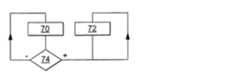
図4は、スクリーン6、8、10を、それぞれY方向、X方向、U方向に沿って変位させるための変位メカニズム20の実行可能な例を示している。この実施形態においては、変位メカニズム20は、スライドレールおよびスライダで構成されている。より詳細に述べると、変位メカニズム20は、次のものを備えている。
− X方向に平行な軸26に沿って、内部をスライダ24がスライドするスライドレール22と、
− Y方向に平行な軸32に沿って、内部をスライダ30がスライドするスライドレール28と、
− U方向に平行な軸40に沿って、内部をスライダ38がスライドするスライドレール36。FIG. 4 shows a feasible example of a
A
A
A
スライドレール22、28、36は、全く自由度なしに、表示装置2のフレームに取り付けられている。スライドレール22、28、36は、それぞれ、スクリーン8、6、10の最大変位可能平面内に位置している。 The slide rails 22, 28, and 36 are attached to the frame of the
スクリーン6、8、10は、全く自由度なしに、それぞれスライダ30、24、38の自由端42、43、44に取り付けられている。 The
図4には、さらに、単に例示の目的だけで、表示装置2のフレームにスクリーン4を取り付けるための取り付け点45を示してある。 FIG. 4 further shows attachment points 45 for attaching the
図4は、さらに、スクリーン6、8、10の変位を、互いに同期させるための同期メカニズム50を示している。この同期メカニズム50によって、スクリーン6、8、10は、それぞれY方向、X方向、U方向に沿って、相互依存的に、すなわち互いに相関的に変位する。例えばスクリーン6、8、10の位置に関わりなく、統合表示面の高さに対する幅の比が一定になるように、同期メカニズム50は作られている。 FIG. 4 further shows a
一例として、同期メカニズム50は、2つの自由端43と44との間で、Y方向に沿って延びる垂直のレール52を備えている。同期メカニズム50は、さらに、2つの自由端42と44との間で、X方向に沿って延びる水平のレール54を備えている。これらのレール52および54は、スクリーン6、8、10の、それぞれの最大変位可能平面内の変位を妨げないように、自由端42、43、44に固定されている。例えばレール52および54は、スクリーン6、8、10の外周上、または外周を越えて位置している。 As an example, the
これらのレール52および54は、スライダ24および30を、それぞれX方向およびY方向に沿って変位させるために、自由端44をU方向に引っ張ったときに発生する張力に抗することができるような、十分な剛性を有している。これらのレール52および54は、それぞれ例えばスライドレールとスライダとによって構成されていてもよい。 These
図5は、スクリーンの位置をロックするためのロッキングメカニズムを示している。このロッキングメカニズム60により、スクリーン6、8、10の並進運動をロックして、スクリーン6、8、10を、引っ込み位置、または完全展開位置、または図2に示されているようないくつかの中間位置に保持することができる。 FIG. 5 shows a locking mechanism for locking the position of the screen. This
例えばロッキングメカニズム60は、スライダ24の、スライドレール22内に位置する端部に形成されたボス62を備えている。このボス62は、スライドレール22に形成されたトラフ64と協働して、スクリーン8の位置をロックする。ボス62は、板ばね66によって、トラフ64の内部に押し付けられている。一連のトラフが、X方向に沿って設けられており、引っ込み位置と完全展開位置との中間のいくつかの中間位置に、スクリーン8をロックすることができる。 For example, the
スクリーン10および6の位置をロックするために、ロッキングメカニズム60のようなロッキングメカニズムを、それぞれU方向およびY方向に沿って設けることもできる。しかしながら、本発明の場合においては、変位を同期させるための同期メカニズム50を用いることによって、スクリーン8の位置をロックすると、スクリーン6および10の位置もロックされるから、そのような必要はない。 A locking mechanism, such as
次に、図6に示す方法を参照して、表示装置2の動作を、より詳細に説明する。 Next, the operation of the
スクリーンは、初期状態において、図1に示されている引っ込み位置にあると仮定する。 Assume that the screen is initially in the retracted position shown in FIG.
これらのスクリーンは、ユーザによって、引っ込み位置から完全展開位置まで変位可能である。これを可能にするために、ユーザは、例えばスクリーン10をU方向に引っ張ることによって、Y方向、X方向、U方向に沿う、それぞれのスクリーン6、8、10の変位を同期させることができる。 These screens can be displaced by the user from a retracted position to a fully deployed position. To make this possible, the user can synchronize the displacement of the
ステップ70において、センサ16は、スクリーン6、8、10のうちの少なくとも1つの、各時刻における位置を測定する。この位置は、リアルタイムに、コンピュータ12に伝達される。 In
同時に、ステップ72において、コンピュータ12は、表示されるべき全体画像を、存在するスクリーン数と同数の部分画像に分割する。この分割は、部分画像の各々が、対応するそれぞれのスクリーン上に表示されたときに、全体画像が統合表示面の全面にわたって、すなわち統合表示面の90%を超過し、かつ最大100%までの面上に表示されるように行われる。ステップ72において、全体画像の、部分画像への分割は、スクリーンの測定された位置、および各スクリーンの個別表示面の既知サイズに基づいて行われる。 At the same time, in
一例として、全体画像の分割のために、最初に、スクリーンの位置に基づいて、X方向およびY方向において利用可能なピクセル数が特定される。利用可能なピクセルとは、Z方向から見たときに、前面に位置しているスクリーンによって覆い隠されないピクセルである。スクリーンが、完全展開位置に向かって変位するにつれて、利用可能なピクセルの総数は増加する。利用可能なピクセルの総数は、1(全てのスクリーンが最大に重ね合わされている時)〜4(最大拡張時)の比率で変化する。各位置において、コンピュータは、その位置において利用可能なピクセル数に応じて、表示されるべき全体画像の最良の分割を決定する。ソース画像の同一点を表示するために、スクリーンの利用可能な2つ以上のピクセルを用いることもある。この際に遂行される演算は、与えられたソース画像を、可変規模のスクリーン(すなわち、X方向および/またはY方向に沿ったピクセル数が可変であるスクリーン)上に表示しなければならないか、そうでなければ、可変解像度のソース画像を、与えられた解像度のスクリーン上に表示しなければならない当業者によって遂行される演算に準ずる。 As an example, for segmenting the entire image, the number of pixels available in the X and Y directions is first identified based on the screen position. An available pixel is a pixel that is not obscured by the front screen when viewed from the Z direction. As the screen is displaced toward the fully expanded position, the total number of available pixels increases. The total number of available pixels varies in a ratio of 1 (when all screens are maximally overlaid) to 4 (when fully expanded). At each location, the computer determines the best division of the entire image to be displayed, depending on the number of pixels available at that location. Two or more available pixels of the screen may be used to display the same point in the source image. The operations performed at this time must display a given source image on a variable scale screen (ie, a screen with a variable number of pixels along the X and / or Y direction), Otherwise, it follows the operations performed by those skilled in the art that must display variable resolution source images on a screen of a given resolution.
分割が行われると、ステップ72において、コンピュータ12は、統合表示面の全面にわたって全体画像を表示するために、分割された各部分画像を、対応するスクリーン上に表示するように制御する。 When the division is performed, in
ステップ72は、新しい画像が表示されるたびに反復される。
ステップ74において、コンピュータ12は、スクリーン6、8、10の変位を検出するために、これらのスクリーンの測定された位置を用いる。例えばコンピュータ12は、新しく測定された位置と、前に測定された位置とを比較する。変位が検出されなかった場合には、この方法はステップ70に戻る。 In
変位が検出された場合には、ステップ72において、コンピュータは、現在表示されている画像のサイズを、スクリーンの変位が検出された後に得られた新しい統合表示面に自動的に適応させる。 If a displacement is detected, in
したがって、コンピュータ12が、表示されている画像を、常に、現在利用可能な統合表示面の全面を占めるように画像処理するから、ユーザが統合表示面を拡げると同時に、表示されている画像のサイズが拡大される。したがって、ユーザにとっては、全体画像の一要素または一部分を拡大表示する必要なく、画像のサイズを拡大することができる新しい方法が得られる。 Therefore, since the
コンピュータ12は、さらに、スクリーンがどのような位置にあろうとも、統合表示面上に全体画像を表示させる。 The
多くの別の実施形態が可能である。特に、スクリーンを変位させるための変位メカニズムに関して、多くの別の実施形態が可能である。例えばこの変位メカニズムに、必ずしも、スライドレールおよび/またはスライダを組み込む必要はない。 Many other embodiments are possible. Many other embodiments are possible, particularly with respect to the displacement mechanism for displacing the screen. For example, it is not always necessary to incorporate slide rails and / or sliders in this displacement mechanism.
X方向およびY方向に沿う変位が、互いに独立して行われるように、変位メカニズムを作ることができる。このようにするために、例えばスライドレール36の端部が、Z方向に平行な回転軸を有する第1の枢動リンクによって、表示装置2のフレームに固定される。例えばこの回転軸は、図2に示されている取り付け点45を通る。次に、スライダ38が、やはりZ方向に平行な回転軸を有する第2の枢動リンクによって、スクリーン10および同期メカニズム50に固定される。 A displacement mechanism can be made such that displacement along the X and Y directions takes place independently of each other. For this purpose, for example, the end of the
同様に、スクリーンの位置をロックするために、別のロッキングメカニズムとすることも可能である。例えばスタッドまたはロックスクリューを用いて、スクリーンの位置をロックすることができる。ロッキングメカニズムは、必ずしも、引っ込み位置と完全展開位置との中間位置をロックすることができる必要はないが、できることが望ましい。 Similarly, another locking mechanism may be used to lock the screen position. For example, the position of the screen can be locked using a stud or a lock screw. The locking mechanism need not necessarily be able to lock an intermediate position between the retracted position and the fully deployed position, but it is desirable to be able to do so.
多くの平面スクリーンを用いることができる。例えばOLEDスクリーンではなく、電気泳動スクリーンを用いることができる。この電気泳動スクリーンは、上部透明層と下部層との間に詰め込まれた黒ビーズ−白ビーズの混合物をベースとするものであってもよい。黒ビーズは、例えば正極性を有しており、白ビーズは、例えば負極性を有している。下部層の下に、電極が配置されている。電極に電圧が印加されると、電極は、例えば正極性のビーズを引き付け、負極性のビーズを遠ざける。したがって、これによって、内側層の近傍に黒ビーズが集中し、上部透明層の近傍に白ビーズが集中する。したがって、この方法により、黒ピクセルと白ピクセルとから成る色を調整し、画像を明確に示すことができる。このような電気泳動スクリーンは、双安定性であり、したがって、電力を消費することなく、画像を表示し続ける。 Many flat screens can be used. For example, an electrophoretic screen can be used instead of an OLED screen. This electrophoretic screen may be based on a mixture of black beads-white beads packed between an upper transparent layer and a lower layer. The black beads have, for example, positive polarity, and the white beads have, for example, negative polarity. An electrode is disposed under the lower layer. When a voltage is applied to the electrode, for example, the electrode attracts positive-polarity beads and moves the negative-polarity beads away. Accordingly, this concentrates black beads near the inner layer and concentrates white beads near the upper transparent layer. Therefore, by this method, the color composed of black pixels and white pixels can be adjusted to clearly show the image. Such electrophoretic screens are bistable and therefore continue to display images without consuming power.
必要に応じて、LCD(液晶ディスプレイ)スクリーンを用いることができる。 If necessary, an LCD (liquid crystal display) screen can be used.
スクリーンとして、タッチスクリーンを用いることもできる。 A touch screen can also be used as the screen.
表示装置を作るために、全てのスクリーンが同じサイズを有する必要はない。相異なるサイズのスクリーンを用いてもよい。さらに、各スクリーンはそれぞれに、図示されているような矩形の個別表示面を有する必要は必ずしもない。個別表示面は、例えばダイヤモンド形状であっても、三角形形状であっても、または、鋭角または鈍角を有する他の形状であってもよい。 Not all screens need to have the same size to make a display. Different size screens may be used. Further, each screen need not necessarily have a rectangular individual display surface as shown. The individual display surface may be, for example, a diamond shape, a triangular shape, or another shape having an acute angle or an obtuse angle.
複数のスクリーンは、一方向にのみ変位しうるものでもよいし、またそれと対照的に、同一直線状にないいくつかの方向に沿って変位することができるものでもよい。さらに、同一のスクリーンが、例えばいくつの方向に引っ張られるかにより、いくつかの相異なる方向に移動するものであってもよい。 The plurality of screens may be displaceable only in one direction, or in contrast, may be displaceable along several directions that are not collinear. Furthermore, the same screen may move in several different directions, for example depending on how many directions it is pulled.
スクリーンの変位を同期させる手段は、省略してもよい。 The means for synchronizing the screen displacement may be omitted.
スクリーンの数は変更してもよい。スクリーンの数は、2以上でなければならないが、5以上、例えば9以上であってもよい。 The number of screens may be changed. The number of screens must be 2 or more, but may be 5 or more, for example 9 or more.
スクリーン間pの互いに相対的な変位を、モータ駆動で行ってもよい。この場合には、スクリーンの変位を同期させるための同期メカニズムは、アクチュエータを用いて、スクリーンの変位を適切に制御することによって得られる。 The relative displacement between the screens p may be performed by motor drive. In this case, the synchronization mechanism for synchronizing the displacement of the screen is obtained by appropriately controlling the displacement of the screen using an actuator.
センサ16は省略してもよい。その場合には、画像のサイズを手動で調整するためのモジュールを、表示装置2内に設ける。 The
さらに、一変形例として、表示されている全体画像の内容を、センサによって測定されたスクリーンの位置に応じて変更することもある。例えば、引っ込み位置においては、画像を、単に、統一表示面の全面を占める初期説明によって構成する。完全展開位置においては、表示されている全体画像は、補足説明で補った同じ初期説明を有している。例えば補足説明は、統合表示面のうちの、完全展開位置に変位することによって現れる補足部分に配置される。統合表示面上に表示される初期説明の大きさは、引っ込み位置と完全展開位置とで同じであることが望ましい。そのようにすると、完全展開位置へのスクリーンの変位によって、補足説明へのアクセスが得られる。これを、街の中心部および郊外の地図の参照に適用することができる。初期説明は、街の中心部のみの地図である。補足説明は、郊外の地図である。この適用においては、スクリーンを、その引っ込み位置から完全展開位置に変位させることによって、ユーザは、より多くの情報、すなわち郊外の地図にアクセスすることができる。 Furthermore, as a modification, the content of the displayed whole image may be changed according to the position of the screen measured by the sensor. For example, in the retracted position, the image is simply composed of an initial description that occupies the entire unified display surface. At the fully expanded position, the displayed whole image has the same initial description supplemented by the supplementary description. For example, the supplementary explanation is arranged in a supplementary portion that appears by displacing to the fully developed position on the integrated display surface. It is desirable that the size of the initial description displayed on the integrated display surface is the same at the retracted position and the fully expanded position. In doing so, access to the supplementary explanation is gained by the displacement of the screen to the fully deployed position. This can be applied to city center and suburban map references. The initial explanation is a map of the city center only. The supplementary explanation is a suburban map. In this application, the user can access more information, ie a suburban map, by displacing the screen from its retracted position to its fully deployed position.
表示されている全体画像を、スクリーンの位置に応じて変更する別の1つの手法は、スクリーンの位置がどうであれ、初期説明が統合表示面の90%を超過する面積を占めるように、スクリーンの変位の方向(1つ以上の)に、初期説明のサイズを拡げることである。 Another technique for changing the entire displayed image according to the screen position is to ensure that the initial description occupies more than 90% of the integrated display surface, regardless of the screen position. Is to expand the size of the initial description in the direction of the displacement (s).
携帯電話またはラップトップコンピューターなどの携帯端末に、表示装置2を用いることができる。さらに、テレビジョンセットなどの固定端末を得るために、表示装置2を実装することもできる。 The
2 表示装置
4、6、8、10 スクリーン
12 コンピュータ
14 メモリ
16 センサ
20 変位メカニズム
22、28、36 スライドレール
24、30、38 スライダ
26、32、40 軸
42、43、44 自由端
45 取り付け点
50 同期メカニズム
52、54 レール
60 ロッキングメカニズム
62 ボス
64 トラフ
66 板ばね2
Claims (9)
Translated fromJapanese− 前記統合表示面の全面にわたって全体画像を表示するように、前記スクリーンの各々上への部分画像の表示を制御することができるコンピュータ(12)
とを備えている表示装置であって、
− 前記表示装置は、前記統合表示面を縮小するために、前記スクリーンのうちの少なくとも2つが重なり合っている引っ込み位置と、前記統合表示面を増加させるために、前記スクリーンの重なり合いが軽減または解除されている完全展開位置との間で、前記表示平面に平行に前記スクリーンを変位させるための変位メカニズム(20)を、さらに備えていること、並びに
− 前記コンピュータは、前記引っ込み位置と前記完全展開位置との両方において、前記統合表示面の全面にわたって全体画像を表示するように制御することができること
を特徴とする表示装置。-When there are multiple screens (4, 6, 8, 10) arranged in parallel to the same display plane, and there is an overlap between the individual display surfaces from the total of the individual display surfaces of each screen Are a plurality of screens (4, 6, 8, 10) forming an integrated display surface of the image, which is equal to the surface of such portion minus the surface,
A computer (12) capable of controlling the display of the partial images on each of the screens so as to display the whole image over the whole of the integrated display surface;
A display device comprising:
The display device has a retracted position where at least two of the screens overlap to reduce the integrated display surface, and the overlap of the screens is reduced or released to increase the integrated display surface; A displacement mechanism (20) for displacing the screen parallel to the display plane between the retracted position and the fully deployed position; and The display device can be controlled so as to display the entire image over the entire surface of the integrated display surface.
− 前記引っ込み位置と前記完全展開位置との両方において、前記統合表示面の全面にわたって全体画像を表示するように制御するステップ(72)
とを含むことを特徴とする、請求項1〜5のいずれか1つに記載の表示装置上に画像を表示する方法。Between a retracted position where at least two screens overlap to reduce the integrated display surface and a fully deployed position where the overlap of the screens is reduced or released to increase the integrated display surface; Displacing the screen parallel to the display plane;
-Controlling to display the entire image over the entire integrated display surface at both the retracted position and the fully deployed position (72);
The method of displaying an image on the display apparatus as described in any one of Claims 1-5 characterized by the above-mentioned.
− 該測定されたスクリーンの位置から、前記スクリーンの変位を検出するステップ(74)と、
− それに応じて、各部分画像を表示するための新しい制御を自動的に開始するステップ
とを含む、請求項6に記載の方法。-Measuring the position of the screen (70);
-Detecting the displacement of the screen from the measured screen position (74);
Accordingly, automatically initiating a new control for displaying each partial image.
Applications Claiming Priority (2)
| Application Number | Priority Date | Filing Date | Title |
|---|---|---|---|
| FR0954267AFR2947090B1 (en) | 2009-06-23 | 2009-06-23 | DISPLAY, DISPLAY METHOD, AND RECORDING MEDIUM FOR THIS METHOD. |
| FR0954267 | 2009-06-23 |
Publications (2)
| Publication Number | Publication Date |
|---|---|
| JP2011008255Atrue JP2011008255A (en) | 2011-01-13 |
| JP5735223B2 JP5735223B2 (en) | 2015-06-17 |
Family
ID=41119819
Family Applications (1)
| Application Number | Title | Priority Date | Filing Date |
|---|---|---|---|
| JP2010141139AExpired - Fee RelatedJP5735223B2 (en) | 2009-06-23 | 2010-06-22 | Display device, display method, and recording medium for the display method |
Country Status (6)
| Country | Link |
|---|---|
| US (1) | US8334818B2 (en) |
| EP (1) | EP2267594B1 (en) |
| JP (1) | JP5735223B2 (en) |
| KR (1) | KR101665424B1 (en) |
| CN (1) | CN101980141B (en) |
| FR (1) | FR2947090B1 (en) |
Cited By (1)
| Publication number | Priority date | Publication date | Assignee | Title |
|---|---|---|---|---|
| JP2023072663A (en)* | 2021-11-12 | 2023-05-24 | エルジー ディスプレイ カンパニー リミテッド | Large area display device and large area display device driving system |
Families Citing this family (5)
| Publication number | Priority date | Publication date | Assignee | Title |
|---|---|---|---|---|
| KR101467663B1 (en)* | 2013-01-30 | 2014-12-01 | 주식회사 엘지씨엔에스 | Method and system of providing display in display monitoring system |
| US20150161937A1 (en)* | 2013-12-05 | 2015-06-11 | Lenovo (Singapore) Pte. Ltd. | Overlapping detection display and method |
| JP6669617B2 (en)* | 2016-09-12 | 2020-03-18 | ルネサスエレクトロニクス株式会社 | Video processing system |
| CN107632808A (en)* | 2017-09-25 | 2018-01-26 | 上海闻泰信息技术有限公司 | Display screen auto-changing terminal and its transform method |
| WO2022144574A1 (en)* | 2020-12-30 | 2022-07-07 | Technogym S.P.A. | Location and position-based display systems and methods |
Citations (4)
| Publication number | Priority date | Publication date | Assignee | Title |
|---|---|---|---|---|
| JPH10222090A (en)* | 1996-10-30 | 1998-08-21 | Hewlett Packard Co <Hp> | Positioning method of connection type movable display screen for portable computer |
| JP2003050655A (en)* | 2001-05-11 | 2003-02-21 | Xerox Corp | Mixed resolution display |
| JP2007114694A (en)* | 2005-10-24 | 2007-05-10 | Pioneer Electronic Corp | Display device and display method |
| JP2007163912A (en)* | 2005-12-15 | 2007-06-28 | Sony Corp | Display section support mechanism, display apparatus and display system |
Family Cites Families (7)
| Publication number | Priority date | Publication date | Assignee | Title |
|---|---|---|---|---|
| US7362046B2 (en)* | 2001-11-10 | 2008-04-22 | Image Portal Limited | Partial overlapping display tiles of organic light emitting device |
| EP1588248A2 (en)* | 2003-01-14 | 2005-10-26 | Koninklijke Philips Electronics N.V. | Rearranging views on a computer screen |
| JP3881330B2 (en)* | 2003-08-27 | 2007-02-14 | 松下電器産業株式会社 | Video display device |
| CN100375952C (en)* | 2005-04-26 | 2008-03-19 | 威盛电子股份有限公司 | Method and device for realizing dynamic image display by using virtual plane coordinate transformation |
| US7898600B2 (en)* | 2005-08-05 | 2011-03-01 | Samsung Electronics Co., Ltd. | Apparatus for providing multiple screens and method of dynamically configuring multiple screens |
| EP1970886B1 (en)* | 2006-01-06 | 2015-06-03 | Unified Innovative Technology, LLC | Mobile terminal device, display method, display program, and recording medium |
| KR100703514B1 (en)* | 2006-04-07 | 2007-04-03 | 삼성에스디아이 주식회사 | Dual screen mobile display devices |
- 2009
- 2009-06-23FRFR0954267Apatent/FR2947090B1/enactiveActive
- 2010
- 2010-06-17EPEP10166394.6Apatent/EP2267594B1/ennot_activeNot-in-force
- 2010-06-22JPJP2010141139Apatent/JP5735223B2/ennot_activeExpired - Fee Related
- 2010-06-23USUS12/821,229patent/US8334818B2/ennot_activeExpired - Fee Related
- 2010-06-23CNCN201010213332XApatent/CN101980141B/ennot_activeExpired - Fee Related
- 2010-06-23KRKR1020100059748Apatent/KR101665424B1/ennot_activeExpired - Fee Related
Patent Citations (4)
| Publication number | Priority date | Publication date | Assignee | Title |
|---|---|---|---|---|
| JPH10222090A (en)* | 1996-10-30 | 1998-08-21 | Hewlett Packard Co <Hp> | Positioning method of connection type movable display screen for portable computer |
| JP2003050655A (en)* | 2001-05-11 | 2003-02-21 | Xerox Corp | Mixed resolution display |
| JP2007114694A (en)* | 2005-10-24 | 2007-05-10 | Pioneer Electronic Corp | Display device and display method |
| JP2007163912A (en)* | 2005-12-15 | 2007-06-28 | Sony Corp | Display section support mechanism, display apparatus and display system |
Cited By (3)
| Publication number | Priority date | Publication date | Assignee | Title |
|---|---|---|---|---|
| JP2023072663A (en)* | 2021-11-12 | 2023-05-24 | エルジー ディスプレイ カンパニー リミテッド | Large area display device and large area display device driving system |
| JP7443459B2 (en) | 2021-11-12 | 2024-03-05 | エルジー ディスプレイ カンパニー リミテッド | Large area display device and large area display device drive system |
| US12027115B2 (en) | 2021-11-12 | 2024-07-02 | Lg Display Co., Ltd. | Large-area display device and large-area display device driving system |
Also Published As
| Publication number | Publication date |
|---|---|
| CN101980141A (en) | 2011-02-23 |
| US20100321276A1 (en) | 2010-12-23 |
| JP5735223B2 (en) | 2015-06-17 |
| EP2267594B1 (en) | 2017-08-30 |
| KR101665424B1 (en) | 2016-10-12 |
| CN101980141B (en) | 2013-09-18 |
| FR2947090B1 (en) | 2011-07-15 |
| FR2947090A1 (en) | 2010-12-24 |
| KR20100138832A (en) | 2010-12-31 |
| US8334818B2 (en) | 2012-12-18 |
| EP2267594A1 (en) | 2010-12-29 |
Similar Documents
| Publication | Publication Date | Title |
|---|---|---|
| JP5735223B2 (en) | Display device, display method, and recording medium for the display method | |
| US20210319613A1 (en) | Systems and methods for displaying representative images | |
| CN207302506U (en) | foldable display device | |
| KR102529503B1 (en) | Display Apparatus and Driving Method of the same | |
| KR100786415B1 (en) | Image display device | |
| WO2016091082A1 (en) | Multi-screen joint display processing method and device | |
| US20110102421A1 (en) | Information processing device, image display method, and computer program | |
| CN111833746B (en) | Flexible display panel, display device and method for controlling display of display device | |
| TWI257596B (en) | Display apparatus | |
| CN104182080B (en) | Semiconductor device and display device | |
| CN108230931B (en) | A kind of display module and electronic equipment | |
| EP2627079A1 (en) | Image displaying apparatus and image displaying method | |
| US8253654B2 (en) | Visual interface control based on viewing display area configuration | |
| JP2012502580A (en) | Display device and method for displaying an image in a display area of variable size | |
| KR20210052708A (en) | Sun visor apparatus for vehicle and method for controlling the same | |
| KR20170048232A (en) | Expanding display type mobile terminal capable of folding reversely | |
| CN110688043B (en) | Double-image display method and device and terminal | |
| CN102810047B (en) | For browsing the apparatus and method of the map shown on the touchscreen | |
| KR20170049777A (en) | Flexible display panel, flexible display device, and the method for driving them flexible display device | |
| KR20090129711A (en) | Electronic picture frame and its image display method | |
| KR20200070657A (en) | Rollable display and driving method thereof | |
| CN104040291A (en) | Map display device and map display method | |
| CN206601563U (en) | Display device | |
| CN202677761U (en) | Multi-screen and multi-angle information interaction device | |
| JP2007114694A (en) | Display device and display method |
Legal Events
| Date | Code | Title | Description |
|---|---|---|---|
| A621 | Written request for application examination | Free format text:JAPANESE INTERMEDIATE CODE: A621 Effective date:20130509 | |
| A977 | Report on retrieval | Free format text:JAPANESE INTERMEDIATE CODE: A971007 Effective date:20140117 | |
| A131 | Notification of reasons for refusal | Free format text:JAPANESE INTERMEDIATE CODE: A131 Effective date:20140204 | |
| A521 | Request for written amendment filed | Free format text:JAPANESE INTERMEDIATE CODE: A523 Effective date:20140507 | |
| A131 | Notification of reasons for refusal | Free format text:JAPANESE INTERMEDIATE CODE: A131 Effective date:20141216 | |
| A521 | Request for written amendment filed | Free format text:JAPANESE INTERMEDIATE CODE: A523 Effective date:20150223 | |
| TRDD | Decision of grant or rejection written | ||
| A01 | Written decision to grant a patent or to grant a registration (utility model) | Free format text:JAPANESE INTERMEDIATE CODE: A01 Effective date:20150331 | |
| A61 | First payment of annual fees (during grant procedure) | Free format text:JAPANESE INTERMEDIATE CODE: A61 Effective date:20150416 | |
| R150 | Certificate of patent or registration of utility model | Ref document number:5735223 Country of ref document:JP Free format text:JAPANESE INTERMEDIATE CODE: R150 | |
| LAPS | Cancellation because of no payment of annual fees |