JP2010540167A - Transluminal endoscopic surgery kit - Google Patents
Transluminal endoscopic surgery kitDownload PDFInfo
- Publication number
- JP2010540167A JP2010540167AJP2010528003AJP2010528003AJP2010540167AJP 2010540167 AJP2010540167 AJP 2010540167AJP 2010528003 AJP2010528003 AJP 2010528003AJP 2010528003 AJP2010528003 AJP 2010528003AJP 2010540167 AJP2010540167 AJP 2010540167A
- Authority
- JP
- Japan
- Prior art keywords
- overtube
- distal end
- patient
- needle
- lumen
- Prior art date
- Legal status (The legal status is an assumption and is not a legal conclusion. Google has not performed a legal analysis and makes no representation as to the accuracy of the status listed.)
- Withdrawn
Links
Images


Classifications
- A—HUMAN NECESSITIES
- A61—MEDICAL OR VETERINARY SCIENCE; HYGIENE
- A61B—DIAGNOSIS; SURGERY; IDENTIFICATION
- A61B17/00—Surgical instruments, devices or methods
- A61B17/00234—Surgical instruments, devices or methods for minimally invasive surgery
- A—HUMAN NECESSITIES
- A61—MEDICAL OR VETERINARY SCIENCE; HYGIENE
- A61B—DIAGNOSIS; SURGERY; IDENTIFICATION
- A61B1/00—Instruments for performing medical examinations of the interior of cavities or tubes of the body by visual or photographical inspection, e.g. endoscopes; Illuminating arrangements therefor
- A61B1/00064—Constructional details of the endoscope body
- A61B1/00071—Insertion part of the endoscope body
- A61B1/0008—Insertion part of the endoscope body characterised by distal tip features
- A61B1/00087—Tools
- A—HUMAN NECESSITIES
- A61—MEDICAL OR VETERINARY SCIENCE; HYGIENE
- A61B—DIAGNOSIS; SURGERY; IDENTIFICATION
- A61B1/00—Instruments for performing medical examinations of the interior of cavities or tubes of the body by visual or photographical inspection, e.g. endoscopes; Illuminating arrangements therefor
- A61B1/00131—Accessories for endoscopes
- A61B1/00135—Oversleeves mounted on the endoscope prior to insertion
- A—HUMAN NECESSITIES
- A61—MEDICAL OR VETERINARY SCIENCE; HYGIENE
- A61B—DIAGNOSIS; SURGERY; IDENTIFICATION
- A61B1/00—Instruments for performing medical examinations of the interior of cavities or tubes of the body by visual or photographical inspection, e.g. endoscopes; Illuminating arrangements therefor
- A61B1/012—Instruments for performing medical examinations of the interior of cavities or tubes of the body by visual or photographical inspection, e.g. endoscopes; Illuminating arrangements therefor characterised by internal passages or accessories therefor
- A61B1/018—Instruments for performing medical examinations of the interior of cavities or tubes of the body by visual or photographical inspection, e.g. endoscopes; Illuminating arrangements therefor characterised by internal passages or accessories therefor for receiving instruments
- A—HUMAN NECESSITIES
- A61—MEDICAL OR VETERINARY SCIENCE; HYGIENE
- A61B—DIAGNOSIS; SURGERY; IDENTIFICATION
- A61B1/00—Instruments for performing medical examinations of the interior of cavities or tubes of the body by visual or photographical inspection, e.g. endoscopes; Illuminating arrangements therefor
- A61B1/313—Instruments for performing medical examinations of the interior of cavities or tubes of the body by visual or photographical inspection, e.g. endoscopes; Illuminating arrangements therefor for introducing through surgical openings, e.g. laparoscopes
- A—HUMAN NECESSITIES
- A61—MEDICAL OR VETERINARY SCIENCE; HYGIENE
- A61B—DIAGNOSIS; SURGERY; IDENTIFICATION
- A61B17/00—Surgical instruments, devices or methods
- A61B17/34—Trocars; Puncturing needles
- A61B17/3417—Details of tips or shafts, e.g. grooves, expandable, bendable; Multiple coaxial sliding cannulas, e.g. for dilating
- A61B17/3421—Cannulas
- A61B17/3423—Access ports, e.g. toroid shape introducers for instruments or hands
- A—HUMAN NECESSITIES
- A61—MEDICAL OR VETERINARY SCIENCE; HYGIENE
- A61B—DIAGNOSIS; SURGERY; IDENTIFICATION
- A61B17/00—Surgical instruments, devices or methods
- A61B17/34—Trocars; Puncturing needles
- A61B17/3478—Endoscopic needles, e.g. for infusion
- A—HUMAN NECESSITIES
- A61—MEDICAL OR VETERINARY SCIENCE; HYGIENE
- A61B—DIAGNOSIS; SURGERY; IDENTIFICATION
- A61B1/00—Instruments for performing medical examinations of the interior of cavities or tubes of the body by visual or photographical inspection, e.g. endoscopes; Illuminating arrangements therefor
- A61B1/00142—Instruments for performing medical examinations of the interior of cavities or tubes of the body by visual or photographical inspection, e.g. endoscopes; Illuminating arrangements therefor with means for preventing contamination, e.g. by using a sanitary sheath
- A—HUMAN NECESSITIES
- A61—MEDICAL OR VETERINARY SCIENCE; HYGIENE
- A61B—DIAGNOSIS; SURGERY; IDENTIFICATION
- A61B1/00—Instruments for performing medical examinations of the interior of cavities or tubes of the body by visual or photographical inspection, e.g. endoscopes; Illuminating arrangements therefor
- A61B1/005—Flexible endoscopes
- A61B1/01—Guiding arrangements therefore
- A—HUMAN NECESSITIES
- A61—MEDICAL OR VETERINARY SCIENCE; HYGIENE
- A61B—DIAGNOSIS; SURGERY; IDENTIFICATION
- A61B17/00—Surgical instruments, devices or methods
- A61B17/00234—Surgical instruments, devices or methods for minimally invasive surgery
- A61B2017/00238—Type of minimally invasive operation
- A61B2017/00278—Transorgan operations, e.g. transgastric
- A—HUMAN NECESSITIES
- A61—MEDICAL OR VETERINARY SCIENCE; HYGIENE
- A61B—DIAGNOSIS; SURGERY; IDENTIFICATION
- A61B17/00—Surgical instruments, devices or methods
- A61B17/34—Trocars; Puncturing needles
- A61B17/3417—Details of tips or shafts, e.g. grooves, expandable, bendable; Multiple coaxial sliding cannulas, e.g. for dilating
- A61B17/3421—Cannulas
- A61B17/3423—Access ports, e.g. toroid shape introducers for instruments or hands
- A61B2017/3425—Access ports, e.g. toroid shape introducers for instruments or hands for internal organs, e.g. heart ports
- A—HUMAN NECESSITIES
- A61—MEDICAL OR VETERINARY SCIENCE; HYGIENE
- A61B—DIAGNOSIS; SURGERY; IDENTIFICATION
- A61B17/00—Surgical instruments, devices or methods
- A61B17/34—Trocars; Puncturing needles
- A61B2017/348—Means for supporting the trocar against the body or retaining the trocar inside the body
- A61B2017/3482—Means for supporting the trocar against the body or retaining the trocar inside the body inside
- A61B2017/3484—Anchoring means, e.g. spreading-out umbrella-like structure
- A61B2017/3488—Fixation to inner organ or inner body tissue
- A—HUMAN NECESSITIES
- A61—MEDICAL OR VETERINARY SCIENCE; HYGIENE
- A61B—DIAGNOSIS; SURGERY; IDENTIFICATION
- A61B90/00—Instruments, implements or accessories specially adapted for surgery or diagnosis and not covered by any of the groups A61B1/00 - A61B50/00, e.g. for luxation treatment or for protecting wound edges
- A61B90/40—Apparatus fixed or close to patients specially adapted for providing an aseptic surgical environment
Landscapes
- Health & Medical Sciences (AREA)
- Life Sciences & Earth Sciences (AREA)
- Surgery (AREA)
- General Health & Medical Sciences (AREA)
- Public Health (AREA)
- Veterinary Medicine (AREA)
- Nuclear Medicine, Radiotherapy & Molecular Imaging (AREA)
- Animal Behavior & Ethology (AREA)
- Molecular Biology (AREA)
- Engineering & Computer Science (AREA)
- Biomedical Technology (AREA)
- Heart & Thoracic Surgery (AREA)
- Medical Informatics (AREA)
- Pathology (AREA)
- Biophysics (AREA)
- Radiology & Medical Imaging (AREA)
- Physics & Mathematics (AREA)
- Optics & Photonics (AREA)
- Surgical Instruments (AREA)
- Infusion, Injection, And Reservoir Apparatuses (AREA)
- Endoscopes (AREA)
Abstract
Translated fromJapaneseDescription
Translated fromJapanese (本発明の背景)
本発明は、概して、内視鏡に関し、より具体的には、経管腔的内視鏡手術キットに関する。(Background of the present invention)
The present invention relates generally to endoscopes, and more specifically to transluminal endoscopic surgery kits.
多くの医療手技は、身体組織に切開を施し、その結果として起こるいずれの出血をもコントロールすることに関与する。これらの手技を行う場合、切開する際の組織の外傷および内出血を止めるために必要な時間の両方を、最小限に留めることが非常に重要である。内視鏡検査を用いて行われる手技等の低侵襲性の手技は、これらの手技を用いると、より侵襲性の高い従来の手技を用いるよりも身体組織の外傷が少ないため、非常に望ましい。 Many medical procedures involve making an incision in body tissue and controlling any resulting bleeding. When performing these procedures, it is very important to minimize both the tissue trauma and the time required to stop internal bleeding during the incision. Minimally invasive procedures such as procedures performed using endoscopy are highly desirable because these procedures cause less trauma to body tissue than using more invasive conventional procedures.
通常の内視鏡手技では、患者は穏やかな鎮静剤を投与され、口または肛門等の自然の開口部を通して、内視鏡の遠位端が消化管内の対象領域付近に位置付けられるまで、内視鏡の遠位端が消化管に挿入される。次に、対象領域に所望の手技を行う際の使用に適した器具が、内視鏡の作業チャネルに挿入される。次いで、内視鏡医は、器具を使用して当該領域に対する手技を行う。手技が完了すると、内視鏡から器具が取り出され、内視鏡が患者から取り出される。 In a normal endoscopic procedure, the patient is given a gentle sedation and passes through a natural opening, such as the mouth or anus, until the distal end of the endoscope is positioned near the area of interest in the gastrointestinal tract. The distal end of the mirror is inserted into the digestive tract. Next, an instrument suitable for use in performing a desired procedure on the target region is inserted into the working channel of the endoscope. The endoscopist then performs a procedure on the area using the instrument. When the procedure is complete, the instrument is removed from the endoscope and the endoscope is removed from the patient.
前述した種類の内視鏡手技の実施例は、特許文献1、特許文献2、特許文献3、および特許文献4に開示され、そのすべてが本明細書に参考として援用される。より具体的には、これらの特許は、胃食道逆流性疾患(GERD)を治療する内視鏡手技を開示する。GERDとは、日常活動および/または睡眠を妨げるほど胸焼けが重度であるか、または頻度が高い状態である。胸焼けは、胃液および胃酸が胃から食道内に入り込み、食道を刺激すると起こる。通常は、下部食道括約筋(LES)と称される輪状の筋肉が、食道と胃の間の弁の役割を果たし、胃液および胃酸が胃から食道内に入り込まないようにしながら、食物が食道から胃の中へと通過できるようにする。LESが、胃液および胃酸を胃の中に維持することができない場合に、胸焼けが起こる。GERDを有する人々の中には、LESが必要以上におよび/または誤った時間に弛緩する人々がいる。頻繁および/または重度の胸焼けをもたらす他に、GERDは、他の健康問題の原因となる可能性がある。例えば、食道内に逆流する胃液および胃酸は、食道の炎症(食道炎)または潰瘍を引き起こす可能性がある。重症の場合、この障害は、食道の粘膜を傷つけて食道を狭め、患者にとって嚥下が困難であるかまたは痛みを伴う、狭窄の原因となる可能性がある。特定の場合、これは、食道の粘膜が変化して、時間の経過とともに癌化する恐れのある、バレット食道と称される状態を引き起こす可能性がある。 Examples of endoscopic procedures of the type described above are disclosed in Patent Document 1, Patent Document 2, Patent Document 3, and Patent Document 4, all of which are incorporated herein by reference. More specifically, these patents disclose endoscopic procedures for treating gastroesophageal reflux disease (GERD). GERD is a condition in which heartburn is severe or frequent enough to interfere with daily activities and / or sleep. Heartburn occurs when gastric juice and acid enter the esophagus from the stomach and irritate the esophagus. Normally, a ring-shaped muscle called the lower esophageal sphincter (LES) acts as a valve between the esophagus and the stomach, preventing food and gastric acid from entering the esophagus from the stomach, while food flows from the esophagus to the stomach. To be able to pass through. Heartburn occurs when LES is unable to maintain gastric juices and acid in the stomach. Some people with GERD relax more than necessary and / or at the wrong time. In addition to causing frequent and / or severe heartburn, GERD can cause other health problems. For example, gastric juice and gastric acid refluxing into the esophagus can cause esophageal inflammation (esophagitis) or ulcers. In severe cases, this disorder can damage the mucosa of the esophagus and narrow the esophagus, leading to stenosis that is difficult or painful for the patient to swallow. In certain cases, this can cause a condition called Barrett's esophagus that can change the mucosa of the esophagus and become cancerous over time.
上記特許に記載される内視鏡手技は、患者の口を通して食道内のLESに近接して内視鏡を挿入することに関与する。次いで、一般的に「注射針」と称されるデバイスの遠位端が、注射針の遠位端がLESの筋肉に挿入されるまで、内視鏡の作業チャネルを通して挿入される。次いで、注射針を通して、LESの筋肉内に特殊な溶液が分注される。溶液は、LESが胃液および胃酸が食道内に戻らないよう維持する助けとなる、柔らかいスポンジ状の永久インプラントを括約筋中に形成する、生体適合性ポリマーを含む。 The endoscopic procedure described in the above patent involves inserting an endoscope through the patient's mouth and close to the LES in the esophagus. The distal end of the device, commonly referred to as the “injection needle”, is then inserted through the working channel of the endoscope until the distal end of the injection needle is inserted into the muscle of the LES. A special solution is then dispensed through the needle into the muscle of the LES. The solution includes a biocompatible polymer that forms a soft sponge-like permanent implant in the sphincter that helps the LES keep gastric juice and acid from returning into the esophagus.
通常は、前述した種類の注射針は、中空針、柔軟な内側カテーテル、柔軟な外側カテーテル、内側ハブ、および外側ハブを備える。中空針の近位端は、通常は、柔軟な内側カテーテルの遠位端内に固定して取り付けられる。内側ハブは、通常は、内側カテーテルの近位端上に固定して取り付けられ、無針注射器等から内側カテーテルに流体を運搬するように適合される。内側カテーテルおよび中空針は、注射を行いたい場合は、外側カテーテルの遠位端から中空針を伸長させることができ、また注射を行わない場合は、中空針を外側カテーテル内に後退させることができるように、通常は、外側カテーテル内に摺動可能に取り付けられる。外側ハブは、通常は、外側カテーテルの近位端上に固定して取り付けられ、かつ内側ハブに係合して、外側カテーテルに対する針および内側カテーテルの遠位の移動を制限するように適合される。注射針の実施例は、以下の特許に開示され、そのすべてが本明細書に参考として援用される。:特許文献5、特許文献6、特許文献7、特許文献8、特許文献9、特許文献10、特許文献11、および特許文献12。 Typically, an injection needle of the type described above comprises a hollow needle, a flexible inner catheter, a flexible outer catheter, an inner hub, and an outer hub. The proximal end of the hollow needle is usually fixedly mounted within the distal end of the flexible inner catheter. The inner hub is typically fixedly mounted on the proximal end of the inner catheter and is adapted to carry fluid from a needleless syringe or the like to the inner catheter. The inner catheter and hollow needle can be extended from the distal end of the outer catheter if injection is desired, and the hollow needle can be retracted into the outer catheter if injection is not desired As such, it is usually slidably mounted within the outer catheter. The outer hub is typically fixedly mounted on the proximal end of the outer catheter and is adapted to engage the inner hub to limit distal movement of the needle and inner catheter relative to the outer catheter. . Examples of needles are disclosed in the following patents, all of which are hereby incorporated by reference: : Patent Literature 5, Patent Literature 6, Patent Literature 7, Patent Literature 8, Patent Literature 9, Patent Literature 10,
新たに台頭してきた医療分野は、NOTES、すなわち、自然の開口部からの経管腔的内視鏡手術(Natural Orifice Transluminal Endoscopic Surgery)である。NOTESでは、自然の開口部を通して挿入され、次いで、消化管の切開を通して腹腔内に通過させられる内視鏡を使用して、腹腔内で内視鏡手技が行われる。より具体的には、NOTESの手技は、通常は、口または肛門等の自然の開口部を通して内視鏡の遠位端を消化管内に挿入し、消化管(例えば、胃、食道、大腸、小腸)内の所望の位置に開口部を形成し、開口部を拡張し、拡張した開口部を通して内視鏡を腹腔内に通過させることに関与する。次いで、内視鏡の遠位端を腔内の標的領域まで進めることができ、内視鏡によって送達された器具を使用して、標的領域上で外科的手技を行うことができる。NOTESが適切である可能性がある手技の実施例には、虫垂切除術および胆嚢摘出術を含む。NOTESが適切である可能性がある他の自然の開口部には、膣および尿道を含む。 A new medical field that has emerged is NOTES, ie, Natural Orifice Transluminal Endoscopic Surgery through natural openings. In NOTES, endoscopic procedures are performed in the abdominal cavity using an endoscope that is inserted through a natural opening and then passed through the digestive tract incision into the abdominal cavity. More specifically, NOTES procedures typically involve inserting the distal end of the endoscope into the digestive tract through a natural opening, such as the mouth or anus, and the digestive tract (eg, stomach, esophagus, large intestine, small intestine). ) To form an opening at a desired position within, expand the opening, and pass the endoscope through the expanded opening into the abdominal cavity. The distal end of the endoscope can then be advanced to the target area within the cavity and a surgical procedure can be performed on the target area using the instrument delivered by the endoscope. Examples of procedures where NOTES may be appropriate include appendectomy and cholecystectomy. Other natural openings where NOTES may be appropriate include the vagina and urethra.
(本発明の概要)
本発明の一局面によると、経管腔的内視鏡手術キットが提供され、経管腔的内視鏡手術キットは、(a)近位端、遠位端、およびチャネルを備えるアクセスチューブと、(b)アクセスチューブのチャネル内への着脱可能な挿入のために適合される手術器具と、(c)オーバーチューブであって、オーバーチューブは、近位端、遠位端、および長手方向に延在する穴を有し、長手方向に延在する穴は、アクセスチューブの遠位端を着脱可能に受容するように適合され、オーバーチューブの遠位端は、患者体内の管腔壁に固着されるように適合される、オーバーチューブとを備える。(Outline of the present invention)
According to one aspect of the present invention, a transluminal endoscopic surgery kit is provided, the transluminal endoscopic surgery kit comprising: (a) an access tube comprising a proximal end, a distal end, and a channel; (B) a surgical instrument adapted for removable insertion into the channel of the access tube, and (c) an overtube, the overtube being proximal, distal, and longitudinally A longitudinally extending bore is adapted to removably receive the distal end of the access tube, the distal end of the overtube being secured to the lumen wall within the patient body And an overtube adapted to be adapted.
本発明の別の局面によると、注射針が提供され、注射針は、(a)内側カテーテルであって、近位端、遠位端、および長手方向の穴を有する内側カテーテルと、(b)中空針であって、中空針は、近位端および遠位端を有し、中空針の近位端は、内側カテーテルの遠位端内で同軸上に取り付けられ、中空針は、少なくとも9ゲージ針の外径を有する、中空針と、(c)外側カテーテルであって、外側カテーテルは、近位端、遠位端、および長手方向の穴を有し、内側カテーテルおよび中空針は、外側カテーテル内で同軸上に取り付けられ、中空針が外側カテーテルの遠位端を越えて遠位に伸長する伸長位置と、中空針が外側カテーテルの遠位端を越えて遠位に伸長しない後退位置との間で、移動可能である、外側カテーテルとを備える。 According to another aspect of the present invention, an injection needle is provided, the injection needle comprising: (a) an inner catheter having an inner catheter having a proximal end, a distal end, and a longitudinal bore; and (b) A hollow needle, the hollow needle having a proximal end and a distal end, the proximal end of the hollow needle being coaxially mounted within the distal end of the inner catheter, wherein the hollow needle is at least 9 gauge A hollow needle having an outer diameter of the needle, and (c) an outer catheter, the outer catheter having a proximal end, a distal end, and a longitudinal bore, the inner catheter and the hollow needle being an outer catheter And an extended position where the hollow needle extends distally beyond the distal end of the outer catheter and a retracted position where the hollow needle does not extend distally beyond the distal end of the outer catheter. And an outer catheter that is movable between.
本発明のさらに別の局面によると、アクセスチューブのためのオーバーチューブが提供され、オーバーチューブは、近位端、遠位端、および長手方向に延在する穴を備え、長手方向に延在する穴は、アクセスチューブの遠位端を着脱可能に受容するように適合され、オーバーチューブの遠位端は、患者体内の管腔壁に固着されるように適合される。 According to yet another aspect of the invention, an overtube for an access tube is provided, the overtube having a proximal end, a distal end, and a longitudinally extending hole, extending longitudinally. The hole is adapted to removably receive the distal end of the access tube and the distal end of the overtube is adapted to be secured to the lumen wall within the patient.
本発明のさらに別の局面によると、アクセスチューブのためのオーバーチューブが提供され、オーバーチューブは、近位端、遠位端、および複数の穴を有する管状部材を備え、複数の穴のうちの1つは、アクセスチューブの遠位端を着脱可能に受容するように適合され、オーバーチューブは、複数の穴のうちの別の1つに配置される締結具をさらに備える。 According to yet another aspect of the invention, an overtube for an access tube is provided, the overtube comprising a tubular member having a proximal end, a distal end, and a plurality of holes, of the plurality of holes One is adapted to removably receive the distal end of the access tube, and the overtube further comprises a fastener disposed in another one of the plurality of holes.
本発明のさらに別の局面によると、針を用いて身体器官にアクセスする方法が提供され、この方法は、(a)オーバーチューブを提供するステップであって、オーバーチューブは、近位端、遠位端、および長手方向に延在する穴を有し、長手方向に延在する穴は、アクセスチューブの遠位端を着脱可能に受容するように適合され、オーバーチューブの遠位端は、患者体内の管腔壁に固着されるように適合される、ステップと、(b)オーバーチューブの近位端を患者の外部に保持しながら、患者体内の管腔にオーバーチューブの遠位端を挿入するステップと、(c)オーバーチューブの近位端を患者の外部に保持しながら、オーバーチューブの遠位端を管腔の壁に固着するステップと、(d)アクセスチューブの遠位端をオーバーチューブに挿入するステップと、(e)アクセスチューブに挿入された穿孔ツールを使用して、管腔の壁に穿孔を形成するステップと、(f)針の遠位端をアクセスチューブに挿入するステップと、(g)針の遠位端を、管腔の壁の穿孔に通過させるステップとを含む。 According to yet another aspect of the invention, a method for accessing a body organ using a needle is provided, the method comprising: (a) providing an overtube, the overtube having a proximal end, a distal end; And a longitudinally extending bore adapted to removably receive the distal end of the access tube, the distal end of the overtube being a patient A step adapted to be secured to the lumen wall within the body; and (b) inserting the distal end of the overtube into the lumen within the patient body while holding the proximal end of the overtube external to the patient. (C) securing the distal end of the overtube to the lumen wall while holding the proximal end of the overtube external to the patient; and (d) overshooting the distal end of the access tube. On the tube (E) forming a perforation in the lumen wall using a drilling tool inserted into the access tube; (f) inserting the distal end of the needle into the access tube; (G) passing the distal end of the needle through a bore in the lumen wall.
本発明のさらなる局面によると、経管腔的手術を行う方法が提供され、この方法は、(a)オーバーチューブを提供するステップであって、オーバーチューブは、近位端、遠位端、および長手方向に延在する穴を有し、長手方向に延在する穴は、アクセスチューブの遠位端を着脱可能に受容するように適合され、オーバーチューブの遠位端は、患者体内の管腔壁に固着されるように適合される、ステップと、(b)オーバーチューブの近位端を患者の外部に保持しながら、患者体内の管腔にオーバーチューブの遠位端を挿入するステップと、(c)オーバーチューブの近位端を患者の外部に保持しながら、オーバーチューブの遠位端を管腔の壁に固着するステップと、(d)オーバーチューブに挿入された穿孔ツールを使用して、管腔の壁に穿孔を形成するステップと、(e)内視鏡の遠位端をオーバーチューブに挿入するステップと、(f)手術器具の遠位端を内視鏡に挿入するステップと、(g)手術器具の遠位端を、管腔の壁の穿孔に通過させるステップと、(h)手術器具を使用して、穿孔を通してアクセスされる標的に外科手技を行うステップとを含む。 According to a further aspect of the invention, there is provided a method for performing transluminal surgery, the method comprising: (a) providing an overtube, the overtube comprising a proximal end, a distal end, and A longitudinally extending bore is adapted to removably receive the distal end of the access tube, the distal end of the overtube being a lumen within the patient body Being adapted to be secured to the wall; and (b) inserting the distal end of the overtube into a lumen within the patient body while holding the proximal end of the overtube external to the patient; (C) securing the distal end of the overtube to the lumen wall while holding the proximal end of the overtube external to the patient; and (d) using a drilling tool inserted into the overtube. On the lumen wall Forming a hole; (e) inserting the distal end of the endoscope into the overtube; (f) inserting the distal end of the surgical instrument into the endoscope; and (g) a surgical instrument. Passing the distal end of the lumen through a perforation in the lumen wall and (h) using a surgical instrument to perform a surgical procedure on a target accessed through the perforation.
本明細書および特許請求の範囲の目的のために、本発明が所与の方向に配置される、または所与の方向から見られる場合に、「上」、「下」、「近位」、「遠位」、「上側」、「下側」、「前」、および「後」等の様々な関係を表す用語が、発明を説明するために使用される。本発明の方向を変えることにより、それに応じて、特定の関係を表す用語を調節する必要がある場合があることを理解されたい。 For purposes of this specification and claims, when the present invention is positioned in or viewed from a given direction, “up”, “down”, “proximal”, Terms describing various relationships such as “distal”, “upper”, “lower”, “front”, and “rear” are used to describe the invention. It should be understood that by changing the direction of the invention, it may be necessary to adjust the terminology representing a particular relationship accordingly.
本発明の様々な目的、特徴、および利点が、以下の説明において一部記載され、また一部はその説明から明らかであるか、または本発明の実施により学ぶことができる。説明では、その一部を成す付属の図面についての言及が行われ、本発明を実施するための様々な実施形態が、例として示される。実施形態は、当業者が本発明を実施することができるよう十分に詳細に説明され、本発明の範囲から逸脱することなく、他の実施形態が用いられてもよく、また、構造上の変更が行われてもよいことを理解されたい。以下の詳細な説明は、したがって、限定的な意味で解釈されるべきではなく、本発明の範囲は、付属の特許請求の範囲によって最善として規定される。 Various objects, features and advantages of the present invention will be set forth in part in the description which follows, and in part will be obvious from the description, or may be learned by practice of the invention. In the description, reference is made to the accompanying drawings that form a part hereof, and various embodiments for carrying out the invention are shown by way of illustration. The embodiments are described in sufficient detail to enable those skilled in the art to practice the invention, and other embodiments may be used and structural changes may be made without departing from the scope of the invention. It should be understood that may be performed. The following detailed description is, therefore, not to be taken in a limiting sense, and the scope of the present invention is best defined by the appended claims.
ここで本明細書に組み込まれ、本明細書の一部を構成する添付の図面は、本発明の様々な実施形態を示し、説明とともに本発明の主旨を説明する役割を果たす。図面において、同様の参照番号は同様の部分を表す。
(好ましい実施形態の詳細な説明)
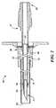
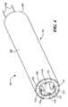
図1を参照すると、本発明の教示にしたがって構成される経管腔的手術キットの第1の実施形態の斜視図が一部切り離されて示され、経管腔的手術キットは、使用前に示されており、好ましくは、無菌状態であり、概して、参照番号11で表される。Detailed Description of Preferred Embodiments
Referring to FIG. 1, a perspective view of a first embodiment of a transluminal surgical kit constructed in accordance with the teachings of the present invention is shown partially cut away, and the transluminal surgical kit is It is shown, preferably sterile, and is generally represented by
例えば、経胃的注射、経食道的注射、または経腸的注射において使用されてもよいキット11は、内視鏡13、注射針15、オーバーチューブ17、および穿孔ツール18を備えてもよい。 For example, a
多くの点で従来の内視鏡に類似してもよい内視鏡13は、近位端19、遠位端21、および長手方向の穴または作業チャネル23を有する、細長い柔軟な部材であってもよい。いくつかの実施形態では、作業チャネル23は、約6mmの直径を有してもよく、内視鏡13は、約10mmの外径を有してもよい。 The
図2においても、その針が完全に後退した位置にある状態で別途示される注射針15は、多くの点で従来の注射針に類似してもよい。注射針15は、中空針31、柔軟な内側カテーテル(または、ステンレススチールもしくはニチノール(ニッケル/チタン合金)ハイポチューブ)33、柔軟な外側カテーテル35、管状内側ハブ37、および管状外側ハブ39を備えてもよい。中空針31の近位端41は、内側カテーテル33の外側の周囲に圧着されてもよい金属帯45によって、柔軟な内側カテーテル33の遠位端43の中に固定して取り付けられてもよい。内側カテーテル33の近位端47は、内側ハブ37の遠位端49の中に固定して取り付けられてもよい。内側ハブ37の近位端51には、外ネジ山が設けられてもよく、かつ従来の無針注射器等への接続のために適合されてもよい。内側カテーテル33および中空針31は、注射を行いたい場合は、外側カテーテル35の遠位端55から中空針31を伸長することができ、また注射を行わない場合は、中空針31を外側カテーテル35内に後退させることができるように、外側カテーテル35内に摺動可能に取り付けられる。外側ハブ39は、外側カテーテル35の近位端57の上に固定して取り付けられてもよく、かつ内側ハブ37に係合して、外側カテーテル35に対する針31および内側カテーテル33の遠位の移動を制限するように適合されてもよい。 Also in FIG. 2, the
注射針15は、内視鏡13の中に着脱可能に取りつけられてもよく、注射針15の遠位端(例えば、針31、内側カテーテル33の遠位端43、外側カテーテル35の遠位端55)は、内視鏡13の作業チャネル23に挿入され、内側ハブ37および外側ハブ39は、好ましくは、作業チャネル23に挿入されていない。所望の場合は、針31、内側カテーテル33、および外側カテーテル35は、作業チャネル23に収容することができる最大の直径であってもよい。したがって、本実施例では、作業チャネル23が4〜8mmの直径を有する場合、針31は、少なくとも9ゲージの針(すなわち、約0.15インチの外径)の大きさであってもよい。上記にかかわらず、所望の場合は、針31、内側カテーテル33、および外側カテーテル35は、光ファイバまたは他の直接的な可視化手段も作業チャネル23に挿入されることができるような、適切な直径であってもよい。 The
腹腔にアクセスする実質的に無菌の環境を提供することが主な役割であるオーバーチューブ17は、近位部51および遠位部53を備えてもよい。近位部51は、近位端52、遠位端54、および長手方向の穴55を有する細長い管状部材であってもよい。穴55は、内視鏡13の遠位端21を同軸上で受容するように適切に寸法決定されてもよく、内視鏡13の近位端19は、好ましくは、穴55の中に挿入されないが、そこから近位に延在する。(本実施形態では、近位部51は円筒形を有しているが、近位部51はそのような形に限定されるものではなく、例えば楕円等の任意の形状を有してもよい。)概して円盤形であってもよい遠位部53は、近位部51の遠位端54の上に位置してもよく、半径方向外向きに延在して外部フランジを画定してもよい。(好ましくは、遠位部53は、食道を通過できるように約20mm以下の外径を有する。)複数の横方向開口部57は、近位部51の半径方向外向きに配される位置で、遠位部53上に均一に離間されてもよい。後にさらに考察されるように、開口部57は、締結具を受容するように寸法決定されてもよい。(あるいは、開口部57は省略されてもよく、遠位部53の外部フランジ部を通して締結具が直接挿入されてもよい)。 The
オーバーチューブ17は、好ましくは、柔軟な生体適合性材料から作られてもよく、シリコーンゴム、熱可塑性エラストマー、ブレードカテーテル、または同様の材料から作られる単一構造であってもよい。あるいは、単一構造である代わりに、近位部51および遠位部53は、別々に製造して後に連結されてもよいか、または遠位部53が近位部51の周囲にオーバーモールドされてもよいか、もしくはその逆であってもよい。 The
従来の穿孔ツールであってもよい穿孔ツール18は、柔軟なチューブ61および貫通ツール63を備えてもよい。シリコーンゴム等から作られてもよいチューブ61は、近位端65および遠位端67を有する、細長い単一部材であってもよい。先鋭化された遠位端69を有する、硬い金属部材であってもよい先端63は、チューブ61の遠位端67内に固定して取り付けられてもよい。 The
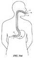
図3(a)から3(f)を参照すると、経管腔的手術キット11が使用されてもよい一様式を概略的に示す様々な図が示される。(これらの図では、キット11は、経胃的注射を行うために使用されている。しかしながら、キット11は、あるいは、例えば経食道的注射、経腸的注射、または身体の自然の開口部もしくは管腔を通して操作する任意の他の手技を行うために使用されてもよいことを理解されたい。)最初に、図3(a)に見られるように、把持器具G(鉗子等)を備える従来の内視鏡Eを使用して、無菌のオーバーチューブ17の遠位部53を把持器具Gで把持し、次いで、遠位部53が患者の胃の中の所望の場所に位置付けられるまで、内視鏡Eの遠位端およびオーバーチューブ17の遠位部53の両方を、患者の口を通して患者の胃の中に挿入する。理解されるように、例えば、遠位部53を患者の胃まで送達する場合、オーバーチューブ17の近位端52は、患者の体内にまったく挿入されない。このように、たとえオーバーチューブ17の遠位端が患者の口を通されても(口は非無菌環境である)、オーバーチューブ17の内部は患者の口に曝露されないため、オーバーチューブ17の内部の無菌性が維持されることができる。さらに、内視鏡Eは、オーバーチューブ17の内部のいずれの部分とも接触しないため、オーバーチューブ17の内部の無菌性は、それ自体は非無菌性であってもよい内視鏡Eによる影響を受けない。次に、図3(b)に見られるように、次いで送達用の内視鏡Eの作業チャネルから器具Gを除去し、内視鏡Eの作業チャネルを使用して、開口部57の向こう側および患者の胃壁Wの向こう側まで、締結具F(例えば、止め金、T字型締結具、クリップ等)を挿入し、そうすることで、オーバーチューブ17を胃壁Wに固着する。(あるいは、締結具は、オーバーチューブ17を患者の体内に挿入する前にオーバーチューブ17に連結されてもよく、オーバーチューブ17を組織に押し当てることによって、または締結具を展開するためのトリガ機構を作動させることによって、締結が行われてもよい。)好ましくは、遠位部53は、無菌性を維持するため、そして漏出または出血を防ぐために、胃(または他の器官)と密接に接触した状態を保つ。次に、図3(c)に見られるように、次いで、内視鏡Eを患者から除去し、内視鏡13の遠位端21がオーバーチューブ17の遠位部53の近くに位置付けられるまで、無菌の内視鏡13をオーバーチューブ17に挿入する。次に、図3(d)に見られるように、無菌の穿孔ツール18を内視鏡13の作業チャネル23に挿入し、次いで、穿孔ツール18を使用してオーバーチューブ17の遠位部53および胃壁Wを穿孔する。次に、図3(e)に見られるように、内視鏡13から穿孔ツール18を除去し、次いで、注射針15の遠位端が腹腔内の標的組織Tの近くに位置付けられるまで、無菌の注射針15の遠位端(針31は完全に後退した位置にある)を、内視鏡13の作業チャネル23、ならびにオーバーチューブ17の穿孔および胃壁Wを通して挿入する。次に、図3(f)に見られるように、注射針15の針31をその伸長位置まで移動し、次いで針31を標的組織Tに挿入する。次いで、従来の様式で、注射針15を通して物質が標的組織Tに分注されてもよい。(あるいは、注射針15を使用して組織Tに物質を分注する代わりに、注射針15は、流体を吸引するため、またさらには組織を除去するために使用されてもよい。)針31は、従来の針よりも内径が大きくてもよいため、針31は、大量の物質、ならびにより高い粘性の物質、および放射性ビーズ、薬物送達マトリクス、膨張性ビーズまたは薬剤、スポンジ等の粒状物質を含む物質を分注するために、より適している可能性があることに留意されたい。標的組織Tへの物質の注射が完了した後で、針31を、その完全に後退した位置まで戻すことができ、次いで、患者から注射針15および内視鏡13を除去する。その後、締結具Fが除去され、オーバーチューブ17が患者から除去される。 Referring to FIGS. 3 (a) through 3 (f), various views are shown that schematically illustrate one manner in which the transluminal
理解されるように、オーバーチューブ17を使用する利点の1つは、体液、血液、糞便、尿、毒素等が、器官または管腔から漏れるのが防止されることである。 As will be appreciated, one of the advantages of using the
本発明の用途の1つは、化学療法剤の部位特異的な送達である。 One application of the present invention is site-specific delivery of chemotherapeutic agents.
前述した方法は、キット11の患者への経口的導入に関与するが、経鼻的アプローチが代替として使用されてもよいことを理解されたい。経口的アプローチまたは経鼻的アプローチのどちらを用いるかを決定する際に考慮されてもよい1つの要因は、患者における標的構造の場所、すなわち、消化管から腹腔内に進入する最適な場所である。考慮されてもよいもう1つの要因は、経鼻的アプローチは、術中の無菌環境に対するより高い必要性を有する可能性があることである。 Although the method described above involves the oral introduction of the
図4を参照すると、キット11を用いた使用のために適合されるオーバーチューブの第1の代替実施形態の透視図が示されており、オーバーチューブは、概して、参照番号101で表される。 Referring to FIG. 4, a perspective view of a first alternative embodiment of an overtube adapted for use with
オーバーチューブ101は、細長い管状部材103を備えてもよい。管状部材103は、シリコーンゴム、熱可塑性エラストマー、または同様の材料等の、柔軟な材料から作られる単一構造であってもよい。管状部材103は、側壁105、開放近位端107、概して管状である遠位端109、および長手方向の穴110を含むように成形されてもよい。(本実施形態では、側壁105は円筒形を有するように示されているが、側壁105は、そのような形に限定されるものではなく、例えば、楕円等の任意の形状を有してもよい。)遠位端109は、複数のタブ111を含むように成形されてもよく、タブ111は、半径方向内向きに短距離で延在する。横方向開口部113は、タブ111の各々に提供されてもよく、各開口部113は、手術用止め金、縫合糸等の締結具を受容するように適合される。また、ストリング115は、互いに正反対に対向する2つのタブ111の各々に固着されてもよく、ストリング115は、穴110を通じて近位に通されるように、かつ後に明らかになる距離の分だけ近位端107を越えて、近位に延在するように適合される。 The
オーバーチューブ101は、薄いフィルム117をさらに備えてもよく、フィルム117は、管状部材103の遠位端109に提供される中央開口部を密封可能に覆う。フィルム117、およびオーバーチューブ101全体の任意の他の部分は、オーバーチューブ101内に配置される内視鏡に提供される可視化手段を使用して、消化管内の所望の場所での遠位端109の適切な設置を保証することができるように、光学的に透明であってもよい。 The
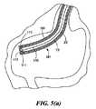
次に、図5(a)から5(e)を参照すると、経管腔的注射を行うために、オーバーチューブ101が、内視鏡13、注射針15、および穿孔ツール18とともに使用されてもよい一様式を概略的に示す様々な図が示される。(これらの図では、経胃的注射が示されている。しかしながら、本発明は、あるいは、経器官的、経管腔的、経食道的、または経腸的注射を行うために使用されてもよいことを理解されたい。)最初に、患者に対して使用する前に、内視鏡13の作業チャネル23を通してストリング115を近位に引きながら、同時に、無菌の内視鏡13を無菌のオーバーチューブ101内に遠位に搭載することができる。(内視鏡13を患者内に挿入しながらストリング115を保持することにより、内視鏡13およびオーバーチューブ101を、並進運動するように互いに連結された状態で維持することができる。)次に、図5(a)に見られるように、次いで、オーバーチューブ101の遠位端109が患者の胃の中の所望の場所に位置付けられるまで、内視鏡13およびオーバーチューブ101の遠位端が、患者の口を通して患者の胃の中に挿入されてもよい。(あるいは、オーバーチューブ101を患者内に挿入し、その後で内視鏡13をオーバーチューブ101に挿入することができるか、または、展開チューブを体内に配置された患者にオーバーチューブ101を挿入し、次いで、オーバーチューブ101および展開チューブを患者内に挿入した後に、展開チューブを内視鏡13と置き換えることができる。)次に、図5(b)に見られるように、内視鏡13の作業チャネル23を使用して、開口部113の向こう側および患者の胃壁Wの向こう側まで、締結具Fを挿入することができ、そうすることで、オーバーチューブ101を胃壁Wに固着する。(あるいは、締結具は、オーバーチューブ101を患者の体内に挿入する前にオーバーチューブ101に連結されてもよく、オーバーチューブ101を組織に押し当てることによって、または締結具を展開するためのトリガ機構を作動させることによって、締結が行われてもよい。)次に、5(c)に見られるように、次いで内視鏡13の作業チャネル23に無菌の穿孔ツール18を挿入して、穿孔ツール18を使用してオーバーチューブ101のフィルム117および胃壁Wを穿孔することができる。次に、5(d)に見られるように、内視鏡13から穿孔ツール18を除去し、次いで、注射針15の遠位端が、腹腔内の標的組織Tの近くに位置付けられるまで、無菌の注射針15の遠位端(針31は完全に後退した位置にある)を、内視鏡13の作業チャネル23、ならびにオーバーチューブ101の穿孔および胃壁Wを通して挿入することができる。次に、5(e)に見られるように、注射針15の針31をその伸長位置まで移動し、次いで針31を標的組織Tに挿入することができる。次いで、従来の様式で、注射針15を通して物質が標的組織Tに分注されてもよい。(あるいは、注射針15を使用して組織Tに物質を分注する代わりに、注射針15は、流体を吸引するため、またさらには組織を除去するために使用されてもよい。)針31は、従来の針よりも内径が大きくてもよいため、針31は、大量の物質、ならびにより高い粘性の物質、および放射性ビーズ、薬物送達マトリクス、膨張性ビーズまたは薬剤、スポンジ等の粒状物質を含む物質を分注するために、より適している可能性があることに留意されたい。標的組織Tへの物質の注射が完了した後で、針31を、その完全に後退した位置まで戻し、次いで、患者から注射針15および内視鏡13を除去することができる。その後、締結具Fが除去されてもよく、オーバーチューブ101が、患者から除去されてもよい。 Next, referring to FIGS. 5 (a) to 5 (e), the
前述した方法は、キット11の患者への経口的導入に関与するが、経鼻的アプローチが代替として使用されてもよいことを理解されたい。経口的アプローチまたは経鼻的アプローチのどちらを用いるかを決定する際に考慮されてもよい1つの要因は、患者における標的構造の場所、すなわち、消化管から腹腔内に進入する最適な場所である。 Although the method described above involves the oral introduction of the
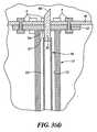
図6(a)および6(b)を参照すると、キット11を用いた使用のために適合されるオーバーチューブの第2の代替実施形態の近位透視図および部分長手方向断面図がそれぞれ示されており、オーバーチューブは、概して、参照番号201で表される。 Referring to FIGS. 6 (a) and 6 (b), there are shown a proximal perspective view and a partial longitudinal cross-sectional view, respectively, of a second alternative embodiment of an overtube adapted for use with the
オーバーチューブ201は、細長い管状部材203を備えてもよい。管状部材203は、シリコーンゴム、熱可塑性エラストマー、または同様の材料等の、好ましくは、柔軟な生体適合性の材料から作られる、単一構造であってもよい。後に考察される理由のために、管状部材203は、例えば、弾性材料で作られることによって、または波形のアコーディオンもしくは折り畳み形を有することによって、半径方向に拡張可能に構成されてもよい。管状部材203は、近位端207および遠位端209で終端する側壁205を含むように成形されてもよい。(本実施形態では、側壁205は円筒形を有するように示されているが、側壁205は、そのような形に限定されるものではなく、例えば楕円等の任意の形状を有してもよい。)光学的に透明であってもよい薄いフィルム210は、オーバーチューブ201内に配置される内視鏡に提供される可視化手段を使用して、消化管内の所望の場所での遠位端209の適切な設置を保証することができるように、遠位端209を密封可能に覆ってもよい。フィルム210は、管状部材203とともに拡張するように、半径方向に拡張可能であってもよい。 The
側壁205は、中央穴211を含むように成形されてもよい。また、第1の複数の長手方向の外周穴213−1から213−4、および第2の複数の長手方向の外周穴215−1から215−4が、側壁205に提供されてもよい。(穴213−1から213−4は、図6(b)において、管状部材203の全長(すなわち、遠位端209から近位端207まで)に延在するように示されているが、代わりに、穴213−1から213−4は、遠位端209の近位から、近位端207の遠位である特定の中間点まで延在してもよいことを理解されたい。例えば、穴213−1から213−4は、遠位部216の長さまで長さが短縮されてもよい。また、穴215−1から215−4は、近位端207から遠位端209まで延在する長手方向の穴である必要があるが、むしろ、近位端207から、壁205を通してアクセス可能である部材203の特定の中間点までの、部材203の長さの一部分のみに延在して、湾曲していてもよい。)穴213−1から213−5の各々は、比較的大きな直径の近位部214および比較的小さな直径の遠位部216を有してもよい。管状部材203を患者に固着するために適した締結具217(例えば、本明細書に参考として援用される米国再発行特許34,021号に開示される)は、穴213−1から213−4の各々に装入されてもよい。生体適合性の材料から作られてもよい締結具217(生分解性であってもよい)は、その一端に配置される遠位の横棒221、およびその反対の端に配置される近位の横棒223を有するフィラメント219を含むように成形されてもよい。遠位の横棒221は、遠位部216内に配置されてもよく、後に記載する様式で遠位の横棒221が遠位部216から押し出されるまで遠位部216内に保留されるように、寸法決定されおよび方向付けられる。近位の横棒223は、その長さが遠位部216の直径を上回り、それによって、遠位部216への挿入を妨げるように、寸法決定されてもよい。 The
押込ロッド231−1から231−4は、それぞれ、穴213−1から213−4の近位部214に摺動可能に配置されてもよい。押込ロッド231−1から231−4は、遠位の横棒221が、フィルム210を通って、またオーバーチューブ201が係止される組織を通って挿入されるまで、締結具217を遠位に押すために使用されてもよい(近位の横棒223の長さおよび方向のために、締結具217の近位端はオーバーチューブ201内に留まる。) The push rods 231-1 to 231-4 may be slidably disposed in the
穴215−1から215−4までのうちの1つは、例えば、オーバーチューブ201の遠位端を固着したい部位の細片を洗浄するために、オーバーチューブ201の遠位端から水等の流体を分注するために使用されてもよい。水の分注は、例えば、そのような各穴内に遠位に挿入されるウォータージェット等を使用して達成されてもよい。あるいは、穴215−1から215−4のうちの1つ以上は、オーバーチューブ201の遠位端から、オーバーチューブ201の遠位端を固着したい部位上に抗生物質を分注するために使用されてもよい。切開部位における感染の可能性を低下させる予防目的のために行われてもよい、標的固着部位への抗生物質の適用は、そのような各穴内に遠位に挿入される分注チューブを使用して達成されてもよい。あるいは、穴215−1から215−4のうちの1つ以上は、オーバーチューブ201の遠位端を固着したい部位に、吸引を適用するために使用されてもよい。これは、オーバーチューブ201の遠位端を固着したい部位から、流体または細片を除去するために行われてもよい。そのような吸引は、そのような各穴内に挿入される吸引チューブを使用して適用されてもよく、吸引チューブの近位端は、真空源等に連結される。あるいは、穴215−1から215−4のうちの1つ以上は、例えば、そのような各穴内に挿入されるファイバ照明を使用して、照明目的のために使用されてもよい。あるいは、穴215−1から215−4のうちの1つ以上は、オーバーチューブ201の遠位端を固着したい部位で、細片をアブレートするためのアブレーションファイバを受容するために使用されてもよい。あるいは、穴215−1から215−4のうちの1つ以上は、一次的な無菌性のための充填剤を分注するために使用されてもよいか、または、一次的な接着剤を適用するために使用されてもよい。 One of the holes 215-1 to 215-4 is formed from a fluid such as water from the distal end of the
理解されるように、フィルム210が穴215−1から215−4の遠位端を覆う場合、穴215−1から215−4の使用を可能にするために、フィルム210の穴215−1から215−4を覆っている領域を穿刺しなければならない。(しかしながら、そのような穿刺は、フィルム210が光学的に透明である場合、および穴が照明および/またはアブレーションの目的に使用される場合には、必要ではない可能性がある。) As will be appreciated, if
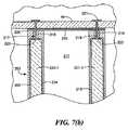
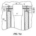
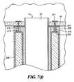
図7(a)から7(h)を参照すると、経管腔的注射を行うためにオーバーチューブ201が使用されてもよい一様式を概略的に示す、様々な図が示される。(これらの図では、経胃的注射が示されている。しかしながら、本発明は、あるいは、経食道的、経器官的、経管腔的、または経腸的注射を行うために使用されてもよいことを理解されたい。)最初に、オーバーチューブ201の遠位端は、図7(a)に示すように、オーバーチューブ201の遠位端が患者の胃の中の所望の場所に位置付けられることができるまで、患者の口を通して患者の胃の中に挿入されてもよい。次に、図7(b)に見られるように、次いで、押込ロッド231を使用して、フィルム210を通って患者の胃壁Wの向こう側まで、締結具217を挿入することができ、そうすることで、オーバーチューブ201を胃壁Wに固着する。(ここで、締結具217は、胃壁Wを穿刺できるように記載されているが、あるいは、ある穿刺デバイスを使用して胃壁を穿刺し、次いで、穿刺された胃壁に締結具217を通過させることができる。)所望の場合は、押込ロッド231は、その後、穴213−1から213−4から除去されてもよい。次に、無菌の内視鏡13をオーバーチューブ201に挿入することができる。無菌の針刀Nまたは他の穿刺デバイスが内視鏡13の作業チャネル23に搭載されてもよく、図7(c)に見られるように、針刀Nは、中央穴211の上に位置するフィルム210のその部分を穿孔するために使用されてもよく、また胃壁Wを穿孔するために使用されてもよい。(あるいは、内視鏡13を通して針刀Nを挿入する代わりに、オーバーチューブ201は、針刀Nが挿入されてもよい専用のチャネルを含んでもよい。)次に、図7(d)に見られるように、ガイドワイヤG(またはガイドチューブ)が胃壁Wの穿孔を通して挿入されてもよい。次に、バルーン等の拡張デバイスBが、オーバーチューブ201の中および胃壁Wの穿孔の向こう側まで挿入されてもよい。次に、図7(e)に見られるように、胃壁Wの穿孔を拡張するため、およびオーバーチューブ201を半径方向に拡張するため、の両方に、拡張デバイスBが使用されてもよい。次に、図7(f)に見られるように、内視鏡13が、胃壁Wの拡張された穿孔を通して挿入されてもよい。次に、図7(g)に見られるように、注射針15の遠位端が、腹腔内の標的組織Tの近くに位置付けられるまで、無菌の注射針15の遠位端(針31は完全に後退した位置にある)を、内視鏡13の作業チャネル23、ならびにフィルム210の穿孔および胃壁Wを通して挿入することができる。次に、図7(h)に見られるように、注射針15の針31をその伸長位置まで移動し、次いで、針31を標的組織Tに挿入することができる。次いで、従来の様式で、注射針15を通して物質が標的組織Tに分注されてもよい。(あるいは、注射針15を使用して組織Tに物質を分注する代わりに、注射針15は、流体を吸引するため、またさらには組織を除去するために使用されてもよい。)針31は、従来の針よりも内径が大きくてもよいため、針31は、大量の物質、ならびにより高い粘性の物質、および放射性ビーズ、薬物送達マトリクス、膨張性ビーズまたは薬剤、スポンジ等の粒状物質を含む物質を分注するために、より適している可能性があることに留意されたい。標的組織Tへの物質の注射が完了した後で、針31を、その完全に後退した位置まで戻し、次いで、患者から注射針15および内視鏡13を除去することができる。その後、例えば、締結具217が壊れるかまたは胃壁Wを通って引き抜かれるまで、オーバーチューブ201を胃壁Wから離れた近位に引くことによって、締結具217が胃壁Wから除去されてもよい。オーバーチューブ201は、その後、患者から除去されてもよい。 Referring to FIGS. 7 (a) to 7 (h), various views are shown that schematically illustrate one manner in which the
上記手技は、比較的大きな切開を胃壁に形成するのとは対照的に、後に拡張される比較的小さな穿孔を胃壁に形成することに関与するという点で望ましい。結果として、本手技は、胃壁のより迅速な治癒を促すことができる。 The above procedure is desirable in that it involves forming a relatively small perforation in the stomach wall that is later expanded, as opposed to making a relatively large incision in the stomach wall. As a result, this procedure can facilitate faster healing of the stomach wall.
前述した方法は、キット11の患者への経口的導入に関与するが、経鼻的アプローチまたは他のアプローチが代替として使用されてもよいことを理解されたい。経口的アプローチ、経鼻的アプローチ、または別の管腔のどちらを用いるかを決定する際に考慮されてもよい1つの要因は、患者における標的構造の場所、すなわち、消化管から腹腔内に進入する最適な場所である。 Although the method described above involves oral introduction of the
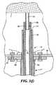
図8を参照すると、キット11を用いた使用のために適合されるオーバーチューブの第3の代替実施形態の部分長手方向断面図が示されており、オーバーチューブは、概して、参照番号301で表される。 Referring to FIG. 8, a partial longitudinal cross-sectional view of a third alternative embodiment of an overtube adapted for use with
オーバーチューブ301は、多くの点でオーバーチューブ201に類似しており、2つのチューブの間の主な相違は、オーバーチューブ201が、対応する複数の締結具217および押込ロッド231を含んでもよいのに対し、オーバーチューブ301は、代わりに、対応する複数のスクリュー303およびスクリュードライバ305を含んでもよいことである。(あるいは、スクリュー303は、先の尖ったらせん構造で置き換えられてもよく、スクリュードライバ305は、回転ロッドで置き換えられてもよい。)オーバーチューブ301の管状部材203を患者に取り付けたい場合は、スクリュードライバ305を使用して、スクリュー303が、穴213およびシール210を通して、次いで、消化管の向こう側まで挿入されてもよい。例えば、外科手技が行われた後で、患者からオーバーチューブ301を除去したい場合は、スクリュードライバ305を使用して消化管からスクリュー303が除去されてもよい。 The
容易に理解されるように、前述した実施形態のいずれにおいても、注射針15は、はさみ、縫合デバイス、把持器具、ホッチキス、生検針、鉗子、止血鉗子、切断ワイヤ、または開腹手術もしくは腹腔鏡手術に適合する他のデバイス等の、1つ以上の他の器具で置き換えることができる(また、注射針15は、先の尖った遠位端を有するハイポチューブのみから構成されてもよい。)また、前述した実施形態のいずれにおいても、無菌の内視鏡は、無菌のアクセスチューブまたは可視化能力を含むかまたは含まないガイドチューブで置き換えることができる。さらに、前述した実施形態のいずれにおいても、穿刺デバイスと注射針、または穿刺デバイスと内視鏡は、なんらかの形で組み合わせられてもよい(例えば、針を通って延在する先の尖った探り針、落下する針の前にあるキャップ、内視鏡上の先の尖ったキャップ、または、本明細書に参考として援用される米国特許第6,497,686号のものと同様のデバイス)。さらに、前述した実施形態のいずれにおいても、穿刺が起こった場合に、穿刺部位に押し込まれるのとは対照的に、穿刺部位から細片が除去されるように、オーバーチューブに吸引を適用する能力を欲してもよい。さらに、前述した実施形態のいずれにおいても、オーバーチューブを、何らかの薬剤、例えば、殺生剤で処理したいと望んでもよい。そのような処理は、薬剤をオーバーチューブのポリマーに組み込むことによって、または薬剤をオーバーチューブの表面(その遠位端の表面等)に適用することによって、または薬剤をオーバーチューブの管腔内に噴出させるもしくは分注することによって、達成されてもよい。 As will be readily appreciated, in any of the previously described embodiments, the
また理解されるように、キット11は、前述した適用に限定されるものではなく、血管または非血管カテーテルの経皮的導入、再配置されて無菌状態を保つ必要のあるスワンガンツカテーテル、胸膜腔にアクセスするための経気管および経胸腔的な胸穿刺の両方による気管支への適用、心膜および心臓への経皮的な胸骨下アプローチ等の、他の適用にも適している可能性がある。 As will also be appreciated, the
前述した本明細書の実施形態は、単に例示であることが意図され、当業者は、本明細書の主旨から逸脱することなく、その多くの変形および修正を作製することができる。そのようなすべての変形および修正は、付属の特許請求の範囲に規定されるように、本明細書の範囲内であることが意図される。 The embodiments described herein are intended to be exemplary only, and many variations and modifications can be made by those skilled in the art without departing from the spirit of the specification. All such variations and modifications are intended to be within the scope of this specification, as defined in the appended claims.
Claims (37)
Translated fromJapanese(b)該アクセスチューブの該チャネル内への着脱可能な挿入のために適合される手術器具と、
(c)オーバーチューブであって、該オーバーチューブは、近位端、遠位端、および長手方向に延在する穴を有し、該長手方向に延在する穴は、該アクセスチューブの該遠位端を着脱可能に受容するように適合され、該オーバーチューブの該遠位端は、患者体内の管腔壁に固着されるように適合される、オーバーチューブと
を備える、経管腔的手術キット。(A) an access tube comprising a proximal end, a distal end, and a channel;
(B) a surgical instrument adapted for removable insertion of the access tube into the channel;
(C) an overtube, the overtube having a proximal end, a distal end, and a longitudinally extending hole, wherein the longitudinally extending hole is at the distal end of the access tube; A transluminal operation comprising: an overtube adapted to removably receive a distal end, and wherein the distal end of the overtube is adapted to be secured to a lumen wall within a patient body kit.
(b)中空針であって、該中空針は、近位端および遠位端を有し、該中空針の該近位端は、該内側カテーテルの該遠位端内で同軸上に取り付けられ、該中空針は、少なくとも9ゲージ針の外径を有する、中空針と、
(c)外側カテーテルであって、該外側カテーテルは、近位端、遠位端、および長手方向の穴を有し、該内側カテーテルおよび該中空針は、該外側カテーテル内で同軸上に取り付けられ、該中空針が該外側カテーテルの該遠位端を越えて遠位に伸長する伸長位置と、該中空針が該外側カテーテルの該遠位端を越えて遠位に伸長しない後退位置との間で、移動可能である、外側カテーテルと
を備える、注射針。(A) an inner catheter having a proximal end, a distal end, and a longitudinal bore;
(B) a hollow needle, the hollow needle having a proximal end and a distal end, the proximal end of the hollow needle being coaxially mounted within the distal end of the inner catheter. The hollow needle has an outer diameter of at least a 9 gauge needle;
(C) an outer catheter, the outer catheter having a proximal end, a distal end, and a longitudinal bore, wherein the inner catheter and the hollow needle are coaxially mounted within the outer catheter. Between an extended position where the hollow needle extends distally beyond the distal end of the outer catheter and a retracted position where the hollow needle does not extend distally beyond the distal end of the outer catheter An injection needle comprising an outer catheter that is movable.
(a)オーバーチューブを提供するステップであって、該オーバーチューブは、近位端、遠位端、および長手方向に延在する穴を有し、該長手方向に延在する穴は、アクセスチューブの遠位端を着脱可能に受容するように適合され、該オーバーチューブの該遠位端は、患者体内の管腔壁に固着されるように適合される、ステップと、
(b)該オーバーチューブの該近位端を患者の外部に保持しながら、該患者体内の管腔に該オーバーチューブの該遠位端を挿入するステップと、
(c)該オーバーチューブの該近位端を該患者の外部に保持しながら、該オーバーチューブの該遠位端を該管腔の壁に固着するステップと、
(d)アクセスチューブの遠位端を該オーバーチューブに挿入するステップと、
(e)該アクセスチューブに挿入された穿孔ツールを使用して、該管腔の該壁に穿孔を形成するステップと、
(f)針の遠位端を該アクセスチューブに挿入するステップと、
(g)該針の該遠位端に、該管腔の該壁の該穿孔を通過させるステップと
を含む、方法。A method of accessing a body organ using a needle, the method comprising:
(A) providing an overtube, the overtube having a proximal end, a distal end, and a longitudinally extending hole, the longitudinally extending hole being an access tube; Adapted to removably receive a distal end of the overtube, the distal end of the overtube being adapted to be secured to a lumen wall within a patient body; and
(B) inserting the distal end of the overtube into a lumen within the patient body while holding the proximal end of the overtube external to the patient;
(C) securing the distal end of the overtube to the lumen wall while holding the proximal end of the overtube external to the patient;
(D) inserting the distal end of the access tube into the overtube;
(E) forming a perforation in the wall of the lumen using a perforation tool inserted into the access tube;
(F) inserting the distal end of a needle into the access tube;
(G) passing the perforation of the wall of the lumen through the distal end of the needle.
(a)オーバーチューブを提供するステップであって、該オーバーチューブは、近位端、遠位端、および長手方向に延在する穴を有し、該長手方向に延在する穴は、内視鏡の遠位端を着脱可能に受容するように適合され、該オーバーチューブの該遠位端は、患者体内の管腔壁に固着されるように適合される、ステップと、
(b)該オーバーチューブの該近位端を患者の外部に保持しながら、該オーバーチューブの該遠位端を該患者体内の管腔に挿入するステップと、
(c)該オーバーチューブの該近位端を該患者の外部に保持しながら、該オーバーチューブの該遠位端を該管腔の壁に固着するステップと、
(d)該オーバーチューブに挿入された穿孔ツールを使用して、該管腔の該壁に穿孔を形成するステップと
を含む、方法。A method for providing a pathway for a transluminal endoscopic procedure comprising:
(A) providing an overtube, the overtube having a proximal end, a distal end, and a longitudinally extending hole, wherein the longitudinally extending hole is Adapted to removably receive a distal end of a mirror, and wherein the distal end of the overtube is adapted to be secured to a lumen wall within a patient body;
(B) inserting the distal end of the overtube into a lumen within the patient while holding the proximal end of the overtube external to the patient;
(C) securing the distal end of the overtube to the lumen wall while holding the proximal end of the overtube external to the patient;
(D) forming a perforation in the wall of the lumen using a perforation tool inserted into the overtube.
Applications Claiming Priority (2)
| Application Number | Priority Date | Filing Date | Title |
|---|---|---|---|
| US99787107P | 2007-10-05 | 2007-10-05 | |
| PCT/US2008/011507WO2009048542A2 (en) | 2007-10-05 | 2008-10-06 | Transluminal endoscopic surgery kit |
Publications (1)
| Publication Number | Publication Date |
|---|---|
| JP2010540167Atrue JP2010540167A (en) | 2010-12-24 |
Family
ID=40377663
Family Applications (1)
| Application Number | Title | Priority Date | Filing Date |
|---|---|---|---|
| JP2010528003AWithdrawnJP2010540167A (en) | 2007-10-05 | 2008-10-06 | Transluminal endoscopic surgery kit |
Country Status (6)
| Country | Link |
|---|---|
| US (2) | US9011320B2 (en) |
| EP (1) | EP2217161B1 (en) |
| JP (1) | JP2010540167A (en) |
| CA (1) | CA2701609C (en) |
| ES (1) | ES2559864T3 (en) |
| WO (1) | WO2009048542A2 (en) |
Families Citing this family (25)
| Publication number | Priority date | Publication date | Assignee | Title |
|---|---|---|---|---|
| AU2008310975B2 (en)* | 2007-10-09 | 2013-08-22 | Cook Medical Technologies Llc | Systems, devices and methods having an overtube for accessing a bodily opening |
| EP2259733B1 (en)* | 2008-03-06 | 2014-07-23 | Cook Medical Technologies LLC | Medical systems for accessing an internal bodily opening |
| WO2009140594A2 (en)* | 2008-05-15 | 2009-11-19 | Wilson-Cook Medical, Inc. | Systems, devices and methods for accessing a bodily opening |
| US8267857B2 (en)* | 2009-01-30 | 2012-09-18 | Cook Medical Technologies Llc | Expandable port for accessing a bodily opening |
| US8834361B2 (en)* | 2009-05-15 | 2014-09-16 | Cook Medical Technologies Llc | Systems, devices and methods for accessing a bodily opening |
| WO2011041669A1 (en)* | 2009-10-02 | 2011-04-07 | Wilson-Cook Medical, Inc. | Apparatus for single port access |
| US9339264B2 (en) | 2010-10-01 | 2016-05-17 | Cook Medical Technologies Llc | Port access visualization platform |
| WO2011041668A1 (en)* | 2009-10-02 | 2011-04-07 | Wilson-Cook Medical, Inc. | Endoscopic fascia tunneling |
| US8475407B2 (en)* | 2010-03-25 | 2013-07-02 | Medtronic, Inc. | Method and apparatus for guiding an external needle to an implantable device |
| US8679151B2 (en)* | 2010-11-24 | 2014-03-25 | Covidien Lp | Access device including shape memory deployment mechanism |
| EP4000497A1 (en) | 2011-02-16 | 2022-05-25 | The General Hospital Corporation | Optical coupler for an endoscope |
| US9022928B2 (en) | 2011-03-18 | 2015-05-05 | Covidien Lp | Wound protector including balloon within incision |
| DE102011107613A1 (en)* | 2011-06-30 | 2013-01-03 | Siegfried Riek | trocar |
| CN104394753A (en)* | 2012-07-13 | 2015-03-04 | 木村正 | Guide tube, guide device, and method for using guide device |
| US9459442B2 (en) | 2014-09-23 | 2016-10-04 | Scott Miller | Optical coupler for optical imaging visualization device |
| US10548467B2 (en) | 2015-06-02 | 2020-02-04 | GI Scientific, LLC | Conductive optical element |
| WO2017015480A1 (en) | 2015-07-21 | 2017-01-26 | GI Scientific, LLC | Endoscope accessory with angularly adjustable exit portal |
| US10582914B2 (en)* | 2016-01-15 | 2020-03-10 | Covidien Lp | Navigable endobronchial tool to access tissue outside a bronchus |
| DE102016009848A1 (en) | 2016-08-16 | 2018-02-22 | Mecus GmbH | Medical device for circumscribed fixation, cleaning and / or germ reduction of a tissue structure |
| EP3773235B1 (en)* | 2018-03-29 | 2023-07-19 | Trice Medical, Inc. | Fully integrated endoscope with biopsy capabilities |
| MX2020010706A (en) | 2018-04-12 | 2021-01-20 | Rocket Science Health Corp | Intranasal drug delivery device, system, and process. |
| WO2020222808A1 (en)* | 2019-04-30 | 2020-11-05 | C.R. Bard, Inc. | Endovascular cutting catheter and related method |
| CN112263285A (en)* | 2020-11-10 | 2021-01-26 | 广东省人民医院 | Percutaneous two-channel endoscope sleeve device |
| US20230165447A1 (en)* | 2021-11-30 | 2023-06-01 | Boston Scientific Scimed, Inc. | External sleeve providing additional working channel |
| WO2024210862A2 (en)* | 2023-04-04 | 2024-10-10 | Koc Universitesi | Surgical instrument port for vaginal natural orifice transluminal endoscopic surgery |
Family Cites Families (28)
| Publication number | Priority date | Publication date | Assignee | Title |
|---|---|---|---|---|
| US3254651A (en)* | 1962-09-12 | 1966-06-07 | Babies Hospital | Surgical anastomosis methods and devices |
| US4624255A (en)* | 1982-02-18 | 1986-11-25 | Schenck Robert R | Apparatus for anastomosing living vessels |
| JPH0216764Y2 (en)* | 1984-10-22 | 1990-05-09 | ||
| US4857057A (en)* | 1985-06-28 | 1989-08-15 | Olympus Optical Co., Ltd. | Endoscope treatment device |
| USRE34021E (en)* | 1985-11-18 | 1992-08-04 | Abbott Laboratories | Percutaneous fixation of hollow organs |
| US4693257A (en)* | 1986-05-12 | 1987-09-15 | Markham Charles W | Needle aspiration biopsy device with enclosed fluid supply |
| JP3003944B2 (en)* | 1990-10-04 | 2000-01-31 | オリンパス光学工業株式会社 | Solid-state imaging device |
| JP3180219B2 (en)* | 1993-07-09 | 2001-06-25 | ニプロ株式会社 | Trocar |
| JP3614943B2 (en)* | 1994-09-29 | 2005-01-26 | オリンパス株式会社 | Endoscopic puncture needle |
| US5964740A (en)* | 1996-07-09 | 1999-10-12 | Asahi Kogaku Kogyo Kabushiki Kaisha | Treatment accessory for an endoscope |
| US5746694A (en)* | 1996-05-16 | 1998-05-05 | Wilk; Peter J. | Endoscope biopsy channel liner and associated method |
| US5785689A (en)* | 1996-07-18 | 1998-07-28 | Act Medical, Inc. | Endoscopic catheter sheath position control |
| US5906594A (en)* | 1997-01-08 | 1999-05-25 | Symbiosis Corporation | Endoscopic infusion needle having dual distal stops |
| US6238335B1 (en)* | 1998-12-11 | 2001-05-29 | Enteric Medical Technologies, Inc. | Method for treating gastroesophageal reflux disease and apparatus for use therewith |
| US6251064B1 (en)* | 1998-12-11 | 2001-06-26 | Enteric Medical Technologies, Inc. | Method for creating valve-like mechanism in natural body passageway |
| US6338345B1 (en)* | 1999-04-07 | 2002-01-15 | Endonetics, Inc. | Submucosal prosthesis delivery device |
| US6358197B1 (en)* | 1999-08-13 | 2002-03-19 | Enteric Medical Technologies, Inc. | Apparatus for forming implants in gastrointestinal tract and kit for use therewith |
| US6497686B1 (en)* | 2000-04-21 | 2002-12-24 | Scimed Life Systems, Inc. | Method and apparatus for performing sterile medical procedures |
| US6585694B1 (en)* | 2000-09-07 | 2003-07-01 | Syntheon, Llc | Knob-controlled endoscopic needle device |
| JP3533163B2 (en)* | 2000-09-18 | 2004-05-31 | ペンタックス株式会社 | Endoscope tip |
| US6911005B2 (en)* | 2001-10-25 | 2005-06-28 | Pentax Corporation | Endoscope with detachable sheath |
| DE602004015729D1 (en)* | 2003-02-11 | 2008-09-25 | Olympus Corp | ABOUT TUBE |
| US7931661B2 (en)* | 2004-06-14 | 2011-04-26 | Usgi Medical, Inc. | Apparatus and methods for performing transluminal gastrointestinal procedures |
| US20060258909A1 (en)* | 2005-04-08 | 2006-11-16 | Usgi Medical, Inc. | Methods and apparatus for maintaining sterility during transluminal procedures |
| EP2037795A2 (en)* | 2006-07-10 | 2009-03-25 | Boston Scientific Limited | Optical spectroscopic injection needle |
| US20080097378A1 (en)* | 2006-08-02 | 2008-04-24 | Zuckerman Stephen D | Optical device for needle placement into a joint |
| JP4875445B2 (en)* | 2006-09-22 | 2012-02-15 | オリンパスメディカルシステムズ株式会社 | Endoscopic treatment tool |
| US8403858B2 (en)* | 2006-10-12 | 2013-03-26 | Perceptive Navigation Llc | Image guided catheters and methods of use |
- 2008
- 2008-10-06WOPCT/US2008/011507patent/WO2009048542A2/enactiveApplication Filing
- 2008-10-06JPJP2010528003Apatent/JP2010540167A/ennot_activeWithdrawn
- 2008-10-06USUS12/287,151patent/US9011320B2/enactiveActive
- 2008-10-06CACA2701609Apatent/CA2701609C/ennot_activeExpired - Fee Related
- 2008-10-06ESES08837305.5Tpatent/ES2559864T3/enactiveActive
- 2008-10-06EPEP08837305.5Apatent/EP2217161B1/enactiveActive
- 2015
- 2015-03-20USUS14/664,058patent/US20150190126A1/ennot_activeAbandoned
Also Published As
| Publication number | Publication date |
|---|---|
| EP2217161B1 (en) | 2015-11-25 |
| CA2701609A1 (en) | 2009-04-16 |
| CA2701609C (en) | 2017-04-18 |
| US20150190126A1 (en) | 2015-07-09 |
| US20090143643A1 (en) | 2009-06-04 |
| WO2009048542A2 (en) | 2009-04-16 |
| WO2009048542A3 (en) | 2009-08-20 |
| EP2217161A2 (en) | 2010-08-18 |
| US9011320B2 (en) | 2015-04-21 |
| ES2559864T3 (en) | 2016-02-16 |
Similar Documents
| Publication | Publication Date | Title |
|---|---|---|
| CA2701609C (en) | Transluminal endoscopic surgery kit | |
| JP7725634B2 (en) | Endoscopic tissue access systems and methods | |
| US8092472B2 (en) | Methods and devices for endoscopic treatment of organs | |
| EP2155082B1 (en) | Tissue securing and sealing apparatus | |
| AU2008335399B2 (en) | Methods and apparatuses for delivering anchoring devices into body passage walls | |
| EP2098186B1 (en) | Transluminal tissue markers | |
| US8361033B2 (en) | Access needle well-suited for percutaneous implantation in a body lumen | |
| US20060258909A1 (en) | Methods and apparatus for maintaining sterility during transluminal procedures | |
| JP5224298B2 (en) | Lumen wall puncture overtube | |
| US20060015006A1 (en) | System and method for accessing a body cavity | |
| EP2166955B1 (en) | Devices for traversing an anatomic wall | |
| JP2009509669A (en) | Transgastric surgery device and procedure | |
| EP3626178B1 (en) | Specimen retrieval device | |
| EP1915098B1 (en) | Gastric instrument sleeve with fixation means | |
| WO2010084869A1 (en) | Guide tube system for forming pneumoperitoneum and providing route for accessing body cavity | |
| WO2025160585A1 (en) | Devices, systems and methods for percutaneously accessing and securing internal organs or other target tissue within a patient | |
| JP2025159023A (en) | Endoscopic tissue access systems and methods | |
| WO2025019771A1 (en) | Devices, systems and methods for percutaneously accessing and securing internal organs or other target tissue within a patient |
Legal Events
| Date | Code | Title | Description |
|---|---|---|---|
| A300 | Application deemed to be withdrawn because no request for examination was validly filed | Free format text:JAPANESE INTERMEDIATE CODE: A300 Effective date:20111206 |