JP2010540041A - Surgical equipment - Google Patents
Surgical equipmentDownload PDFInfo
- Publication number
- JP2010540041A JP2010540041AJP2010526047AJP2010526047AJP2010540041AJP 2010540041 AJP2010540041 AJP 2010540041AJP 2010526047 AJP2010526047 AJP 2010526047AJP 2010526047 AJP2010526047 AJP 2010526047AJP 2010540041 AJP2010540041 AJP 2010540041A
- Authority
- JP
- Japan
- Prior art keywords
- jaw
- rotary drive
- drive shaft
- shaft
- surgical
- Prior art date
- Legal status (The legal status is an assumption and is not a legal conclusion. Google has not performed a legal analysis and makes no representation as to the accuracy of the status listed.)
- Granted
Links
Images


Classifications
- A—HUMAN NECESSITIES
- A61—MEDICAL OR VETERINARY SCIENCE; HYGIENE
- A61B—DIAGNOSIS; SURGERY; IDENTIFICATION
- A61B17/00—Surgical instruments, devices or methods
- A61B17/068—Surgical staplers, e.g. containing multiple staples or clamps
- A—HUMAN NECESSITIES
- A61—MEDICAL OR VETERINARY SCIENCE; HYGIENE
- A61B—DIAGNOSIS; SURGERY; IDENTIFICATION
- A61B17/00—Surgical instruments, devices or methods
- A61B17/068—Surgical staplers, e.g. containing multiple staples or clamps
- A61B17/072—Surgical staplers, e.g. containing multiple staples or clamps for applying a row of staples in a single action, e.g. the staples being applied simultaneously
- A61B17/07207—Surgical staplers, e.g. containing multiple staples or clamps for applying a row of staples in a single action, e.g. the staples being applied simultaneously the staples being applied sequentially
- A—HUMAN NECESSITIES
- A61—MEDICAL OR VETERINARY SCIENCE; HYGIENE
- A61B—DIAGNOSIS; SURGERY; IDENTIFICATION
- A61B90/00—Instruments, implements or accessories specially adapted for surgery or diagnosis and not covered by any of the groups A61B1/00 - A61B50/00, e.g. for luxation treatment or for protecting wound edges
- A61B90/90—Identification means for patients or instruments, e.g. tags
- A61B90/98—Identification means for patients or instruments, e.g. tags using electromagnetic means, e.g. transponders
- A—HUMAN NECESSITIES
- A61—MEDICAL OR VETERINARY SCIENCE; HYGIENE
- A61B—DIAGNOSIS; SURGERY; IDENTIFICATION
- A61B17/00—Surgical instruments, devices or methods
- A61B2017/00017—Electrical control of surgical instruments
- A61B2017/00199—Electrical control of surgical instruments with a console, e.g. a control panel with a display
- A—HUMAN NECESSITIES
- A61—MEDICAL OR VETERINARY SCIENCE; HYGIENE
- A61B—DIAGNOSIS; SURGERY; IDENTIFICATION
- A61B17/00—Surgical instruments, devices or methods
- A61B2017/00367—Details of actuation of instruments, e.g. relations between pushing buttons, or the like, and activation of the tool, working tip, or the like
- A61B2017/00398—Details of actuation of instruments, e.g. relations between pushing buttons, or the like, and activation of the tool, working tip, or the like using powered actuators, e.g. stepper motors, solenoids
- A—HUMAN NECESSITIES
- A61—MEDICAL OR VETERINARY SCIENCE; HYGIENE
- A61B—DIAGNOSIS; SURGERY; IDENTIFICATION
- A61B17/00—Surgical instruments, devices or methods
- A61B2017/0046—Surgical instruments, devices or methods with a releasable handle; with handle and operating part separable
- A61B2017/00464—Surgical instruments, devices or methods with a releasable handle; with handle and operating part separable for use with different instruments
- A—HUMAN NECESSITIES
- A61—MEDICAL OR VETERINARY SCIENCE; HYGIENE
- A61B—DIAGNOSIS; SURGERY; IDENTIFICATION
- A61B17/00—Surgical instruments, devices or methods
- A61B2017/00681—Aspects not otherwise provided for
- A61B2017/00734—Aspects not otherwise provided for battery operated
- A—HUMAN NECESSITIES
- A61—MEDICAL OR VETERINARY SCIENCE; HYGIENE
- A61B—DIAGNOSIS; SURGERY; IDENTIFICATION
- A61B17/00—Surgical instruments, devices or methods
- A61B17/068—Surgical staplers, e.g. containing multiple staples or clamps
- A61B17/072—Surgical staplers, e.g. containing multiple staples or clamps for applying a row of staples in a single action, e.g. the staples being applied simultaneously
- A61B2017/07214—Stapler heads
- A—HUMAN NECESSITIES
- A61—MEDICAL OR VETERINARY SCIENCE; HYGIENE
- A61B—DIAGNOSIS; SURGERY; IDENTIFICATION
- A61B17/00—Surgical instruments, devices or methods
- A61B17/28—Surgical forceps
- A61B17/29—Forceps for use in minimally invasive surgery
- A61B17/2909—Handles
- A61B2017/2912—Handles transmission of forces to actuating rod or piston
- A61B2017/2923—Toothed members, e.g. rack and pinion
- A—HUMAN NECESSITIES
- A61—MEDICAL OR VETERINARY SCIENCE; HYGIENE
- A61B—DIAGNOSIS; SURGERY; IDENTIFICATION
- A61B17/00—Surgical instruments, devices or methods
- A61B17/28—Surgical forceps
- A61B17/29—Forceps for use in minimally invasive surgery
- A61B2017/2926—Details of heads or jaws
- A—HUMAN NECESSITIES
- A61—MEDICAL OR VETERINARY SCIENCE; HYGIENE
- A61B—DIAGNOSIS; SURGERY; IDENTIFICATION
- A61B17/00—Surgical instruments, devices or methods
- A61B17/28—Surgical forceps
- A61B17/29—Forceps for use in minimally invasive surgery
- A61B2017/2926—Details of heads or jaws
- A61B2017/2932—Transmission of forces to jaw members
- A61B2017/2943—Toothed members, e.g. rack and pinion
Landscapes
- Health & Medical Sciences (AREA)
- Surgery (AREA)
- Life Sciences & Earth Sciences (AREA)
- Molecular Biology (AREA)
- Animal Behavior & Ethology (AREA)
- Veterinary Medicine (AREA)
- Nuclear Medicine, Radiotherapy & Molecular Imaging (AREA)
- Public Health (AREA)
- Engineering & Computer Science (AREA)
- Biomedical Technology (AREA)
- Heart & Thoracic Surgery (AREA)
- Medical Informatics (AREA)
- General Health & Medical Sciences (AREA)
- Oral & Maxillofacial Surgery (AREA)
- Physics & Mathematics (AREA)
- Electromagnetism (AREA)
- Pathology (AREA)
- Surgical Instruments (AREA)
Abstract
Translated fromJapaneseDescription
Translated fromJapanese (関連出願の相互参照)
本願は、米国仮特許出願第60/974,267号(2007年9月21日出願)の利益を主張し、この出願はその全体が本明細書に参照により援用される。(Cross-reference of related applications)
This application claims the benefit of US Provisional Patent Application No. 60 / 974,267 (filed Sep. 21, 2007), which is hereby incorporated by reference in its entirety.
(参照による取込み)
本願は、下記の出願の各々の全体を参照によりに援用する:
米国特許出願第11/191,851号(2007年7月27日出願);米国特許出願第10/460,291号(2003年6月11日出願);米国特許出願第10/099,634号(2002年3月15日出願);米国特許出願第09/999,546号(2001年11月30日出願);米国特許出願第09/887,789号(2001年6月22日出願であって、2006年4月25日に米国特許第7,032,798号として発行);米国特許出願第09/836,781号(2001年4月17日出願であって、2006年1月3日に米国特許第6,981,941号として発行);米国特許出願第09/723,715号(2000年11月28日出願であって,2004年9月21日に米国特許第6,793,652号として発行);米国特許出願第09/324,451号(1999年6月2日出願であって、2001年11月13日に米国特許第6,315,184号として発行);米国特許出願第09/324,452号(1999年6月2日出願であって、2002年9月3日に米国特許第6,443,973号として発行);米国特許出願第09/351,534号(1999年7月12日出願であって、2001年7月24日に米国特許第6,264,087号として発行);米国特許出願第09/510,923号(2000円2月22日出願であって、2003年2月11日に米国特許第6,517,565号として発行);および米国特許出願第09/510,927号(2000年2月22日出願であって、2004年4月6日に米国特許6,716,233号として発行)。(Incorporation by reference)
This application incorporates each of the following applications by reference in their entirety:
U.S. Patent Application No. 11 / 191,851 (filed July 27, 2007); U.S. Patent Application No. 10 / 460,291 (filed Jun. 11, 2003); U.S. Patent Application No. 10 / 099,634 (Filed on March 15, 2002); US patent application No. 09 / 999,546 (filed on November 30, 2001); US patent application No. 09 / 887,789 (filed on June 22, 2001) Issued on April 25, 2006 as US Pat. No. 7,032,798; US patent application Ser. No. 09 / 836,781 (filed April 17, 2001, filed January 3, 2006). Issued as U.S. Patent No. 6,981,941); U.S. Patent Application No. 09 / 723,715 (filed on Nov. 28, 2000, U.S. Patent No. 6,793, Sep. 21, 2004). With 652 U.S. Patent Application No. 09 / 324,451 (filed on June 2, 1999 and issued on Nov. 13, 2001 as U.S. Patent No. 6,315,184); 09 / 324,452 (filed on June 2, 1999 and issued as US Pat. No. 6,443,973 on September 3, 2002); US Patent Application No. 09 / 351,534 ( Filed on July 12, 1999 and issued on July 24, 2001 as US Pat. No. 6,264,087; US Patent Application No. 09 / 510,923 (filed on February 22, 2000) Issued as US Pat. No. 6,517,565 on Feb. 11, 2003); and US patent application Ser. No. 09 / 510,927 (filed Feb. 22, 2000, April 2004). US patent on 6th , It issued as No. 716,233).
(発明の分野)
本発明は、外科用装置に関する。より具体的には、本発明は、組織を締め付け、切断し、ステープルで固定するための電動回転および/または関節運動する装置に関する。(Field of Invention)
The present invention relates to a surgical device. More specifically, the present invention relates to an electrically rotating and / or articulating device for clamping, cutting and stapling tissue.
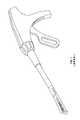
1つの種類の外科用装置は、直線状の締め付け、切断、およびステープル固定の装置である。そのような装置は、胃腸管から癌または異常組織を切除するために外科的手技で使用されてもよい。1つの直線状締め付け、切断、およびステープル固定の器具を図1に示す。装置は、細長い軸および遠位部分を有する、ピストルグリップ型構造を含む。遠位部分は、結腸の開放端を閉鎖して締め付ける、一対の鋏型把持要素を含む。この装置では、アンビル部分等の2つの鋏型把持要素のうちの一方は、全体構造に対して移動または枢動するが、他方の把持要素は、全体構造に対して固定されたままである。この鋏切断装置の作動(アンビル部分の枢動)は、ハンドルの中で維持されたグリップトリガによって制御されてもよい。 One type of surgical device is a linear clamping, cutting, and stapling device. Such a device may be used in a surgical procedure to remove cancer or abnormal tissue from the gastrointestinal tract. One linear clamping, cutting and stapling instrument is shown in FIG. The device includes a pistol grip type structure having an elongated shaft and a distal portion. The distal portion includes a pair of saddle gripping elements that close and clamp the open end of the colon. In this device, one of the two saddle-shaped gripping elements, such as the anvil portion, moves or pivots with respect to the overall structure, while the other gripping element remains fixed with respect to the overall structure. The operation of this scissor cutting device (pivoting of the anvil part) may be controlled by a grip trigger maintained in the handle.
鋏切断装置に加えて、遠位部分は、ステープル固定機構も含む。挟切断機構の固定把持要素は、ステープルカートリッジ受容領域と、アンビル部分に対する組織の締め付けられた端を通してステープルを駆動し、それにより、事前に開かれた端を密閉するための機構とを含む。鋏切断要素は、軸と一体化して形成されてもよく、または、種々の鋏切断およびステープル固定要素が交換可能であってもよいように着脱可能であってもよい。 In addition to the scissor cutting device, the distal portion also includes a staple securing mechanism. The fixed gripping element of the nip-cutting mechanism includes a staple cartridge receiving area and a mechanism for driving the staples through the clamped end of the tissue relative to the anvil portion, thereby sealing the pre-opened end. The scissor cutting element may be formed integrally with the shaft or may be removable so that the various scissor cutting and stapling elements may be interchangeable.
先述の外科用装置に関する、具体的には、図1に図示されるもの等の、先述の直線状締め付け、切断、およびステープル固定の装置に関する1つの問題は、対向ジョーは患者体内で操縦しにくい場合があるということである。対向ジョーの間に所望の組織を配置するために、外科医が種々の角度の間で対向ジョーを動かすことが必要な場合がある。しかしながら、可能な限り小さい切開を患者に行うことも概して望ましく、切開の小さいサイズは、対向ジョーが操縦されてもよい程度を限定する。 One problem with the previously described linear clamping, cutting, and stapling devices, such as that illustrated in FIG. 1, with respect to the previously described surgical device, is that the opposing jaws are difficult to maneuver within the patient. There are cases. It may be necessary for the surgeon to move the opposing jaws between various angles in order to place the desired tissue between the opposing jaws. However, it is also generally desirable to make the smallest possible incision in the patient, and the small size of the incision limits the extent to which the opposing jaws may be steered.
先述の外科用装置に関する、具体的には、図1に図示されるもの等の、先述の直線状締め付け、切断、およびステープル固定装置に関する別の問題は、対向ジョーが十分に止血しない場合があるということである。具体的には、先述の外科用装置の対向ジョーは、十分な力で固く閉じられず、それにより、外科用装置の有効性を低減する。先述の外科用装置に関する、具体的には、図1に図示されるもの等の、先述の直線状締め付け、切断、およびステープル固定装置に関するさらに別の問題は、切断および/またはステープル固定部材が十分なトルクで駆動されず、それにより、外科用装置の有効性を低減することである。 Another problem with the previously described linear clamping, cutting, and stapling device, such as that illustrated in FIG. 1, with respect to the previously described surgical device, may be that the opposing jaws do not stop sufficiently. That's what it means. Specifically, the opposing jaws of the aforementioned surgical device are not tightly closed with sufficient force, thereby reducing the effectiveness of the surgical device. Yet another problem with the above-described linear clamping, cutting, and stapling apparatus, such as that illustrated in FIG. 1, particularly with respect to the aforementioned surgical apparatus, is that the cutting and / or stapling member is sufficient. It is not driven with a strong torque, thereby reducing the effectiveness of the surgical device.
したがって、締め付け、切断、およびステープル固定の装置の操縦性の改善の必要性があると考えられる。加えて、付加的な締め付け、切断、およびステープル固定力を提供する、締め付け、切断、およびステープル固定装置の必要性があると考えられる。 Thus, there appears to be a need for improved maneuverability of the clamping, cutting and stapling devices. In addition, there may be a need for a clamping, cutting and stapling device that provides additional clamping, cutting and stapling forces.
本発明の実施形態例によれば、外科用装置が提供され、外科用装置は、第1の運動機能を果たすための第1のドライバと、第2の運動機能を果たすための第2のドライバと、作動時に、第1および第2のドライバのうちの1つの第2の回転型駆動軸との選択的係合を引き起こすように構成される、第1の回転型駆動軸とを含み、第2の回転型駆動軸は、第1および第2のドライバのうちの選択に係合された1つを駆動するように構成される。 According to an example embodiment of the present invention, a surgical device is provided, the surgical device comprising a first driver for performing a first motor function and a second driver for performing a second motor function. And a first rotary drive shaft configured to cause selective engagement with a second rotary drive shaft of one of the first and second drivers in operation, and The two rotary drive shafts are configured to drive one engaged in the selection of the first and second drivers.
実施形態では、外科用装置はまた、第3の運動機能を果たすための第3のドライバをも含み、第1の回転型駆動軸は、第1、第2、および第3のドライバのうちの選択された1つの第2の回転型駆動軸との係合を引き起こすように構成され、第2の回転型駆動軸は、第1、第2、および第3のドライバのうちの選択的に係合された1つを駆動するように構成される。また、外科用装置は、第3の運動機能を果たすための第4のドライバを含んでもよく、第1の回転型駆動軸は、第2の回転型駆動軸との第1、第2、第3、および第4のドライバのうちの1つの選択的係合を引き起こすように構成され、第2の回転型駆動軸は、第1、第2、第3、および第4のドライバのうちの選択的に係合された1つを駆動するように構成される。 In an embodiment, the surgical device also includes a third driver for performing a third motion function, wherein the first rotary drive shaft is one of the first, second, and third drivers. Configured to cause engagement with one selected second rotary drive shaft, the second rotary drive shaft being selectively engaged among the first, second, and third drivers. It is configured to drive the combined one. The surgical device may also include a fourth driver for performing a third motion function, wherein the first rotary drive shaft is first, second, second with respect to the second rotary drive shaft. The second rotary drive shaft is configured to cause selective engagement of one of the third and fourth drivers, and the second rotary drive shaft is selected from the first, second, third, and fourth drivers Configured to drive one engaged mechanically.
種々の運動機能は、外科用装置によって果たされてもよい。例えば、外科用装置は、ハンドルに連結される軸部分を含んでもよく、ハンドルは、長手軸を画定する。第1および第2の運動機能のうちの少なくとも1つは、第2の回転型駆動軸の作動時に、外科用装置のハンドルに対して、および外科用装置の長手軸の周囲で、外科用装置の軸部分を回転させるステップを含んでもよい。第1の回転方向への第2の回転型駆動軸の作動は、ハンドルに対して、およびハンドルの前記長手軸の周りで、第1の回転方向に軸部分の枢動運動を引き起こしてもよく、第2の回転方向への第2の回転型駆動軸の作動は、ハンドルに対して、およびハンドルの長手軸の周りで、第1の回転方向とは反対の第2の回転方向に軸部分の枢動運動を引き起こしてもよい。第1および第2のドライバは、第1の回転型駆動軸が、第1および第2の運動機能のうちの少なくとも1つに対応する位置に機能的構成要素を動かすと、第2の回転型駆動軸によって選択的に係合される、少なくとも1つの歯車を含んでもよい。 Various motor functions may be performed by the surgical device. For example, the surgical device may include a shaft portion that is coupled to the handle, the handle defining a longitudinal axis. At least one of the first and second motor functions is the surgical device upon actuation of the second rotary drive shaft, relative to the handle of the surgical device and about the longitudinal axis of the surgical device. A step of rotating the shaft portion of the. Actuation of the second rotary drive shaft in the first rotational direction may cause a pivoting movement of the shaft portion in the first rotational direction relative to the handle and about the longitudinal axis of the handle. Actuation of the second rotary drive shaft in the second rotational direction is a shaft portion in a second rotational direction opposite to the first rotational direction relative to the handle and about the longitudinal axis of the handle May cause a pivoting movement. The first and second drivers move to the second rotational type when the first rotational drive shaft moves the functional component to a position corresponding to at least one of the first and second motion functions. It may include at least one gear selectively engaged by the drive shaft.
外科用装置によって果たされてもよい別の運動機能では、外科用装置は、軸部分に連結されるジョー部分を含んでもよく、第1または第2の運動機能は、第2の回転型駆動軸の作動時に、外科用装置の軸部分に対して外科用装置のジョー部分を動かすステップを含んでもよい。第1の回転方向への第2の回転型駆動軸の作動は、軸部分に対して第1の回転方向にジョー部分の枢動運動を引き起こしてもよく、第2の回転方向への第2の回転型駆動軸の作動は、軸部分に対して第1の回転方向とは反対の第2の回転方向にジョー部分の枢動運動を引き起こしてもよい。ジョー部分および軸部分は、それぞれの長手軸を画定してもよく、ジョー部分は、ジョー部分および軸部分の長手軸に垂直である長手軸の周りで軸部分に対して枢動してもよい。第1または第2のドライバは、第1の回転型駆動軸が、第1および第2の運動機能のうちの少なくとも1つに対応する位置に機能的構成要素を動かすと、第2の回転型駆動軸によって選択的に係合される、少なくとも1つの歯車を含んでもよい。 In another motion function that may be performed by the surgical device, the surgical device may include a jaw portion coupled to the shaft portion, the first or second motion function being the second rotational drive. Moving the jaw portion of the surgical device relative to the shaft portion of the surgical device upon actuation of the shaft may be included. Actuation of the second rotary drive shaft in the first rotational direction may cause a pivoting movement of the jaw portion in the first rotational direction relative to the shaft portion, and a second in the second rotational direction. Actuation of the rotary drive shaft may cause the jaw portion to pivot in a second rotational direction opposite to the first rotational direction relative to the shaft portion. The jaw portion and the shaft portion may define respective longitudinal axes, and the jaw portion may pivot relative to the shaft portion about a longitudinal axis that is perpendicular to the longitudinal axis of the jaw portion and the shaft portion. . The first or second driver moves the second rotational type when the first rotational drive shaft moves the functional component to a position corresponding to at least one of the first and second motion functions. It may include at least one gear selectively engaged by the drive shaft.
外科用装置によって果たされてもよい別の運動機能では、外科用装置は、相互に対向して対応している第1のジョーおよび第2のジョーを含む、ジョー部分を含んでもよく、第1または第2の運動機能は、第2の回転型駆動軸の作動時に、第2のジョーに対して第1のジョーを動かすステップを含んでもよい。第1の回転方向への第2の回転型駆動軸の作動は、第2のジョーに対して第1の回転方向に第1のジョーの運動を引き起こしてもよく、第2の回転方向への第2の回転型駆動軸の作動は、第2のジョーに対して第1の回転方向とは反対の第2の回転方向に第1のジョーの枢動運動を引き起こしてもよい。第1または第2のジョーは、それぞれの長手軸を画定してもよく、第1のジョーは、第1および第2のジョーの長手軸に垂直である長手軸の周りで第2のジョーに対して枢動してもよい。第1または第2のドライバは、第1の回転型駆動軸が、第1および第2の運動機能のうちの少なくとも1つに対応する位置に機能的構成要素を動かすと、第2の回転型駆動軸によって選択的に係合される、少なくとも1つの歯車を含んでもよい。 In another motor function that may be performed by the surgical device, the surgical device may include a jaw portion that includes a first jaw and a second jaw that correspond in opposition to each other, The first or second motion function may include moving the first jaw relative to the second jaw upon actuation of the second rotary drive shaft. Actuation of the second rotary drive shaft in the first rotational direction may cause movement of the first jaw in the first rotational direction relative to the second jaw and in the second rotational direction. Actuation of the second rotary drive shaft may cause the first jaw to pivot in a second rotational direction opposite to the first rotational direction relative to the second jaw. The first or second jaw may define a respective longitudinal axis, and the first jaw is a second jaw about a longitudinal axis that is perpendicular to the longitudinal axis of the first and second jaws. You may pivot against it. The first or second driver moves the second rotational type when the first rotational drive shaft moves the functional component to a position corresponding to at least one of the first and second motion functions. It may include at least one gear selectively engaged by the drive shaft.
外科用装置によって果たされてもよい別の運動機能では、外科用装置は、第1のジョーと、第1のジョーと対向して対応している第2のジョーであって、外科用部材を含む第2のジョーとを含んでもよい。第1および第2の運動機能のうちの少なくとも1つは、第2の回転型駆動軸の作動時に、第2のジョー内で外科用部材を駆動するステップを含んでもよい。第1の回転方向への第2の回転型駆動軸の作動は、第2のジョー内で第1の方向に外科用部材の運動を引き起こしてもよく、第2の回転方向への第2の回転型駆動軸の作動は、第2のジョー内で第1の方向とは反対の第2の方向に外科用部材の運動を引き起こしてもよい。外科用部材は、切断要素およびステープル固定要素のうちの少なくとも1つを含んでもよい。第1または第2のドライバは、第1の回転型駆動軸が、第1および第2の運動機能のうちの少なくとも1つに対応する位置に機能的構成要素を動かすと、第2の回転型駆動軸によって選択的に係合される、少なくとも1つの歯車を含んでもよい。 In another kinematic function that may be performed by the surgical device, the surgical device is a first jaw and a second jaw oppositely corresponding to the first jaw, the surgical member And a second jaw including At least one of the first and second motion functions may include driving a surgical member within the second jaw upon actuation of the second rotary drive shaft. Actuation of the second rotational drive shaft in the first rotational direction may cause movement of the surgical member in the first direction within the second jaw, and the second rotational direction in the second rotational direction. Actuation of the rotary drive shaft may cause movement of the surgical member in a second direction opposite to the first direction within the second jaw. The surgical member may include at least one of a cutting element and a staple fixing element. The first or second driver moves the second rotational type when the first rotational drive shaft moves the functional component to a position corresponding to at least one of the first and second motion functions. It may include at least one gear selectively engaged by the drive shaft.
実施形態では、第1および第2の回転型駆動軸は、電気機械ドライバの各駆動連結部に連結可能である。代替として、外科用装置はまた、少なくとも1つのモータであって、第1および第2の回転型駆動軸を回転させるように構成される、少なくとも1つのモータを含んでもよい。 In the embodiment, the first and second rotary drive shafts can be connected to each drive connecting portion of the electromechanical driver. Alternatively, the surgical device may also include at least one motor that is configured to rotate the first and second rotary drive shafts.
別の実施形態では、少なくとも1つのモータユニットを含む電気機械ドライバユニットと、外科用付属部品であって、第1の運動機能を果たすための第1のドライバと、第2の運動機能を果たすための第2のドライバと、少なくとも1つのモータユニットに連結可能であり、少なくとも1つのモータユニットによる作動時に、第2の回転型駆動軸との第1および第2のドライバのうちの1つの選択的係合を引き起こすように構成される、第1の回転型駆動軸とを含む、外科用付属部品とを含む、外科用システムが提供され、第2の回転型駆動軸は、少なくとも1つのモータユニットに連結可能であり、少なくとも1つのモータユニットを介して、第1および第2のドライバのうちの選択的に係合された1つを駆動するように構成される。 In another embodiment, an electromechanical driver unit that includes at least one motor unit, a surgical accessory, a first driver for performing a first motion function, and a second motion function The second driver and at least one motor unit, and when activated by the at least one motor unit, selectively one of the first and second drivers with the second rotary drive shaft A surgical system is provided that includes a surgical accessory including a first rotary drive shaft configured to cause engagement, wherein the second rotary drive shaft includes at least one motor unit. And is configured to drive a selectively engaged one of the first and second drivers via at least one motor unit.
また、外科用システムの外科用付属部品はさらに、第3の運動機能を果たすための第3のドライバを含んでもよく、第1の回転型駆動軸は、作動時に、第2の回転型駆動軸との第1、第2、および第3のドライバのうちの1つの選択的係合を引き起こすように構成され、第2の回転型駆動軸は、第1、第2、および第3のドライバのうちの選択的に係合された1つを駆動するように構成される。加えて、外科用付属部品はまた、第3の運動機能を果たすための第4のドライバを含んでもよく、第1の回転型駆動軸は、作動時に、第2の回転型駆動軸との第1、第2、第3、および第4のドライバのうちの1つの選択的係合を引き起こすように構成され、第2の回転型駆動軸は、第1、第2、第3、および第4のドライバのうちの選択的に係合された1つを駆動するように構成される。 The surgical accessory of the surgical system may further include a third driver for performing a third motion function, wherein the first rotary drive shaft, in operation, is the second rotary drive shaft. And the second rotary drive shaft is configured to cause selective engagement of one of the first, second, and third drivers with the first, second, and third drivers. It is configured to drive one of the selectively engaged ones. In addition, the surgical accessory may also include a fourth driver for performing a third motion function, wherein the first rotary drive shaft is in operation with the second rotary drive shaft. The second rotary drive shaft is configured to cause selective engagement of one of the first, second, third, and fourth drivers, the first, second, third, and fourth Configured to drive a selectively engaged one of the drivers.
実施形態では、外科用システムの外科用付属部品は、ハンドルに連結される軸部分を含み、ハンドルは、長手軸を画定し、第1および第2の運動機能のうちの少なくとも1つは、第2の回転型駆動軸の作動時に、外科用装置のハンドルに対して、および外科用装置のハンドルの長手軸の周りで、外科用装置の軸部分を回転させるステップを含む。第1の回転方向への第2の回転型駆動軸の少なくとも1つのモータユニットを介した作動は、ハンドルに対して、およびハンドルの長手軸の周りで、第1の回転方向に軸部分の枢動運動を引き起こしてもよく、第2の回転方向への第2の回転型駆動軸の少なくとも1つのモータユニットを介した作動は、ハンドルに対して、およびハンドルの長手軸の周りで、第1の回転方向とは反対の第2の回転方向に軸部分の枢動運動を引き起こしてもよい。第1または第2のドライバは、第1の回転型駆動軸が、第1および第2の運動機能のうちの少なくとも1つに対応する位置に機能的構成要素を動かすと、第2の回転型駆動軸によって選択的に係合される、少なくとも1つの歯車を含んでもよい。 In an embodiment, the surgical accessory of the surgical system includes a shaft portion coupled to the handle, the handle defines a longitudinal axis, and at least one of the first and second motion functions is the first Rotating the axial portion of the surgical device relative to the surgical device handle and about the longitudinal axis of the surgical device handle upon actuation of the two rotary drive shafts. Actuation via the at least one motor unit of the second rotary drive shaft in the first rotational direction is pivotal of the shaft portion in the first rotational direction relative to the handle and about the longitudinal axis of the handle. Actuating via the at least one motor unit of the second rotary drive shaft in the second rotational direction in relation to the handle and about the longitudinal axis of the handle. The pivotal movement of the shaft portion may be caused in a second rotational direction opposite to the rotational direction of. The first or second driver moves the second rotational type when the first rotational drive shaft moves the functional component to a position corresponding to at least one of the first and second motion functions. It may include at least one gear selectively engaged by the drive shaft.
実施形態では、外科用システムの外科用付属部品は、軸部分に連結されるジョー部分を含み、第1および第2の運動機能のうちの少なくとも1つは、第2の回転型駆動軸の少なくとも1つのモータユニットを介した駆動時に、外科用装置の軸部分に対して外科用装置のジョー部分を動かすステップを含む。第1の回転方向への第2の回転型駆動軸の少なくとも1つのモータユニットを介した作動は、軸部分に対して第1の回転方向にジョー部分の枢動運動を引き起こしてもよく、第2の回転方向への第2の回転型駆動軸の少なくとも1つのモータユニットを介した作動は、軸部分に対して第1の回転方向とは反対の第2の回転方向にジョー部分の枢動運動を引き起こしてもよい。ジョー部分および軸部分は、それぞれの長手軸を画定してもよく、ジョー部分は、ジョー部分および軸部分の長手軸に垂直である長手軸の周りで軸部分に対して枢動してもよい。第1または第2のドライバは、第1の回転型駆動軸が、第1および第2の運動機能のうちの少なくとも1つに対応する位置に機能的構成要素を動かすと、第2の回転型駆動軸によって選択的に係合される、少なくとも1つの歯車を含んでもよい。 In an embodiment, the surgical accessory of the surgical system includes a jaw portion coupled to the shaft portion, wherein at least one of the first and second motion functions is at least of the second rotary drive shaft. Moving the jaw portion of the surgical device relative to the shaft portion of the surgical device when driven through one motor unit. Actuation via the at least one motor unit of the second rotary drive shaft in the first rotational direction may cause a pivoting movement of the jaw portion in the first rotational direction relative to the shaft portion, Actuation of the second rotary drive shaft in the two rotational directions via the at least one motor unit pivots the jaw part in a second rotational direction opposite to the first rotational direction relative to the shaft part May cause exercise. The jaw portion and the shaft portion may define respective longitudinal axes, and the jaw portion may pivot relative to the shaft portion about a longitudinal axis that is perpendicular to the longitudinal axis of the jaw portion and the shaft portion. . The first or second driver moves the second rotational type when the first rotational drive shaft moves the functional component to a position corresponding to at least one of the first and second motion functions. It may include at least one gear selectively engaged by the drive shaft.
実施形態では、外科用システムの外科用付属部品は、相互に対向して対応している第1のジョーおよび第2のジョーを含む、ジョー部分を含んでもよく、第1または第2の運動機能は、第2の回転型駆動軸の少なくとも1つのモータユニットを介した作動時に、第2のジョーに対して第1のジョーを動かすステップを含んでもよい。第1の回転方向への第2の回転型駆動軸の少なくとも1つのモータユニットを介した作動は、第2のジョーに対して第1の回転方向に第1のジョーの運動を引き起こしてもよく、第2の回転方向への第2の回転型駆動軸の少なくとも1つのモータユニットを介した作動は、第2のジョーに対して第1の回転方向とは反対の第2の回転方向に第1のジョーの枢動運動を引き起こしてもよい。第1および第2のジョーは、それぞれの長手軸を画定してもよく、第1のジョーは、第1および第2のジョーの長手軸に垂直である長手軸の周りで第2のジョーに対して枢動してもよい。第1または第2のドライバは、第1の回転型駆動軸が、第1および第2の運動機能のうちの少なくとも1つに対応する位置に機能的構成要素を動かすと、第2の回転型駆動軸によって選択的に係合される、少なくとも1つの歯車を含んでもよい。 In an embodiment, the surgical accessory of the surgical system may include a jaw portion including a first jaw and a second jaw that correspond in opposition to each other, the first or second motion function. May include moving the first jaw relative to the second jaw when actuated via at least one motor unit of the second rotary drive shaft. Actuation via the at least one motor unit of the second rotary drive shaft in the first rotational direction may cause movement of the first jaw in the first rotational direction relative to the second jaw. , The operation of the second rotary drive shaft in the second rotational direction via the at least one motor unit in a second rotational direction opposite to the first rotational direction relative to the second jaw. It may cause a pivoting movement of one jaw. The first and second jaws may define respective longitudinal axes, the first jaws being in the second jaw about a longitudinal axis that is perpendicular to the longitudinal axes of the first and second jaws. You may pivot against it. The first or second driver moves the second rotational type when the first rotational drive shaft moves the functional component to a position corresponding to at least one of the first and second motion functions. It may include at least one gear selectively engaged by the drive shaft.
実施形態では、外科用システムの外科用付属部品は、第1のジョーと、第1のジョーと対向して対応している第2のジョーであって、外科用部材を含む第2のジョーとを含み、第1および第2の運動機能のうちの少なくとも1つは、第2の回転型駆動軸の少なくとも1つのモータユニットを介した作動時に、第2のジョー内で外科用部材を駆動するステップを含む。第1の回転方向への第2の回転型駆動軸の少なくとも1つのモータユニットを介した作動は、第2のジョー内で第1の方向に外科用部材の運動を引き起こしてもよく、第2の回転方向への第2の回転型駆動軸の少なくとも1つのモータユニットを介した作動は、第2のジョー内で第1の方向とは反対の第2の方向に外科用部材の運動を引き起こしてもよい。外科用部材は、切断要素およびステープル固定要素のうちの少なくとも1つを含んでもよい。第1または第2のドライバは、第1の回転型駆動軸が、第1および第2の運動機能のうちの少なくとも1つに対応する位置に機能的構成要素を動かすと、第2の回転型駆動軸によって選択的に係合される、少なくとも1つの歯車を含んでもよい。 In an embodiment, the surgical accessory of the surgical system is a first jaw and a second jaw oppositely corresponding to the first jaw, the second jaw including a surgical member; And at least one of the first and second motion functions drives the surgical member within the second jaw upon actuation via the at least one motor unit of the second rotary drive shaft Includes steps. Actuation via the at least one motor unit of the second rotary drive shaft in the first rotational direction may cause movement of the surgical member in the first direction within the second jaw, Actuation of the second rotary drive shaft in the direction of rotation of the second rotary drive shaft via the at least one motor unit causes movement of the surgical member in the second jaw in a second direction opposite to the first direction. May be. The surgical member may include at least one of a cutting element and a staple fixing element. The first or second driver moves the second rotational type when the first rotational drive shaft moves the functional component to a position corresponding to at least one of the first and second motion functions. It may include at least one gear selectively engaged by the drive shaft.
実施形態では、外科用システムはまた、モータユニットを制御するように構成される制御システムを含んでもよい。制御システムは、筐体内に配置されてもよい。また、制御システムは、外科用付属部品上に載置される少なくとも1つの制御装置を含んでもよく、制御装置は、無線遠隔制御ユニットを含んでもよい。外科用付属部品は、第1の回転型駆動軸によって可動である機能構成要素に対応する位置センサであって、機能構成要素の位置に対応する信号を出力するセンサを含んでもよい。第2の回転型駆動軸は、機能構成要素の位置に基づいて第1および/または第2のドライバと選択的に係合するように構成されてもよい。 In an embodiment, the surgical system may also include a control system configured to control the motor unit. The control system may be disposed in the housing. The control system may also include at least one control device mounted on the surgical accessory, and the control device may include a wireless remote control unit. The surgical accessory may include a position sensor corresponding to a functional component movable by the first rotary drive shaft and outputting a signal corresponding to the position of the functional component. The second rotary drive shaft may be configured to selectively engage the first and / or second driver based on the position of the functional component.
別の実施形態では、第2のジョーと対向して対応している第1のジョーを有する、ジョー部分であって、第2のジョーは、外科用部材を含む、ジョー部分と、ジョー部分の近位端に連結される軸部分と、長手軸を画定するハンドルとを含む、外科用装置が提供される。外科用装置はまた、ハンドルに対して、およびハンドルの長手軸の周りで、外科用装置の軸部分を回転させるための第1のドライバと、軸部分に対してジョー部分を動かすための第2のドライバと、第2のジョーに対して第1のジョーを動かすための第3のドライバと、第2のジョー内で外科用部材を動かすための第4のドライバとを含んでもよい。加えて、外科用装置はまた、作動時に、第2の回転型駆動軸との第1、第2、第3、および第4のドライバのうちの少なくとも1つの選択的係合を引き起こすように構成される、第1の回転型駆動軸を含んでもよい。 In another embodiment, a jaw portion having a first jaw oppositely corresponding to a second jaw, the second jaw including a surgical member; A surgical device is provided that includes a shaft portion coupled to the proximal end and a handle defining a longitudinal axis. The surgical device also includes a first driver for rotating the shaft portion of the surgical device relative to the handle and about the longitudinal axis of the handle, and a second for moving the jaw portion relative to the shaft portion. And a third driver for moving the first jaw relative to the second jaw and a fourth driver for moving the surgical member within the second jaw. In addition, the surgical device is also configured to cause selective engagement of at least one of the first, second, third, and fourth drivers with the second rotary drive shaft upon actuation. The first rotary drive shaft may be included.
そのような実施形態では、外科用装置は、第1の回転型駆動軸が、第2の回転型駆動軸との第1のドライバの係合を引き起こすと、第1の回転方向への第2の回転型駆動軸の作動が、ハンドルに対して、およびハンドルの長手軸の周りで、第1の回転方向に軸部分の枢動運動を引き起こし、第2の回転方向への第2の回転型駆動軸の作動が、ハンドルに対して、およびハンドルの長手軸の周りで、第1の回転方向とは反対の第2の回転方向に軸部分の枢動運動を引き起こすように、配設されてもよい。また、外科用装置は、第1の回転型駆動軸が、第2の回転型駆動軸との第2のドライバの係合を引き起こすと、第1の回転方向への第2の回転型駆動軸の作動が、軸部分に対して第1の回転方向にジョー部分の枢動運動を引き起こし、第2の回転方向への第2の回転型駆動軸の作動が、軸部分に対して第1の回転方向とは反対の第2の回転方向にジョー部分の枢動運動を引き起こすように、配設されてもよい。さらに、外科用装置は、ジョー部分および軸部分がそれぞれの長手軸を画定するように配設されてもよく、ジョー部分は、ジョー部分および軸部分の長手軸に垂直である長手軸の周りで軸部分に対して枢動する。 In such an embodiment, the surgical device provides a second rotational direction in the first rotational direction when the first rotational drive shaft causes engagement of the first driver with the second rotational drive shaft. Of the rotary drive shaft causes a pivotal movement of the shaft portion in the first rotational direction relative to the handle and about the longitudinal axis of the handle, and the second rotational type in the second rotational direction. Arranged so that actuation of the drive shaft causes a pivoting movement of the shaft portion relative to the handle and about the longitudinal axis of the handle in a second rotational direction opposite to the first rotational direction. Also good. The surgical device also includes a second rotational drive shaft in the first rotational direction when the first rotational drive shaft causes engagement of the second driver with the second rotational drive shaft. Actuation of the jaw portion causes a pivoting movement of the jaw portion in a first rotational direction relative to the shaft portion, and actuation of the second rotary drive shaft in the second rotational direction corresponds to the first rotational direction relative to the shaft portion. It may be arranged to cause a pivoting movement of the jaw part in a second direction of rotation opposite to the direction of rotation. Further, the surgical device may be arranged such that the jaw portion and the shaft portion define respective longitudinal axes, the jaw portion being around a longitudinal axis that is perpendicular to the longitudinal axis of the jaw portion and the shaft portion. Pivot with respect to the shaft part.
外科用装置は、第1の回転型駆動軸が、第2の回転型駆動軸との第3のドライバの係合を引き起こすと、第1の回転方向への第2の回転型駆動軸の作動が、第2のジョーに対して第1の回転方向に第1のジョーの運動を引き起こし、第2の回転方向への第2の回転型駆動軸の作動が、第2のジョーに対して第1の回転方向とは反対の第2の回転方向に第1のジョーの枢動運動を引き起こすように、配設されてもよい。そのような配設では、第1および第2のジョーは、それぞれの長手軸を画定しもよく、第1のジョーは、第1および第2のジョーの長手軸に垂直である長手軸の周りで第2のジョーに対して枢動してもよい。 The surgical device operates the second rotary drive shaft in the first rotational direction when the first rotary drive shaft causes engagement of the third driver with the second rotary drive shaft. Causes movement of the first jaw in the first rotational direction relative to the second jaw, and actuation of the second rotary drive shaft in the second rotational direction causes the second jaw to move in the first rotational direction. It may be arranged to cause a pivoting movement of the first jaw in a second rotation direction opposite to the one rotation direction. In such an arrangement, the first and second jaws may define respective longitudinal axes, wherein the first jaw is about a longitudinal axis that is perpendicular to the longitudinal axes of the first and second jaws. May pivot with respect to the second jaw.
また、外科用装置は、第1の回転型駆動軸が、第2の回転型駆動軸との第3のドライバの係合を引き起こすと、第1の回転方向への第2の回転型駆動軸の作動が、第2のジョーに対して第1の方向に外科用部材の運動を引き起こし、第2の回転方向への第2の回転型駆動軸の作動が、第2のジョーに対して第1の方向とは反対の第2の方向に外科用部材の運動を引き起こすように、配設されてもよい。 The surgical device also includes a second rotary drive shaft in the first rotational direction when the first rotary drive shaft causes the engagement of the third driver with the second rotary drive shaft. Actuation of the surgical member causes movement of the surgical member in a first direction relative to the second jaw, and actuation of the second rotary drive shaft in the second rotational direction results in movement of the second rotational drive shaft relative to the second jaw. It may be arranged to cause movement of the surgical member in a second direction opposite to the one direction.
実施形態では、第1および第2の回転型駆動軸は、電気機械ドライバの各駆動連結部に連結可能であってもよい。代替として、外科用装置は、少なくとも1つのモータであって、第1および第2の回転型駆動軸を回転させるように構成される、少なくとも1つのモータを含んでもよい。 In the embodiment, the first and second rotary drive shafts may be connectable to each drive connecting portion of the electromechanical driver. Alternatively, the surgical device may include at least one motor that is configured to rotate the first and second rotary drive shafts.
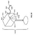
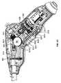
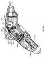
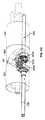
図2(b)は、本発明の実施形態例による、外科用装置11の構成要素のうちのいくつかを図示する概略図である。外科用装置11は、例えば、カニューレ(図示せず)を介した、患者の体内への挿入に特によく適するよう構成される。示された実施形態では、外科用装置11は、締め付け、切断、およびステープル固定の装置である。外科用装置11は、ヒンジ部分11cによって軸部分11bに枢動可能に連結されるジョー部分11aを含む。ジョー部分11aは、遠位端50aおよび近位端50bを有する第1のジョー50と、遠位端80aおよび近位端80bを有する第2のジョー80とを含む。第1のジョー50および第2のジョー80は、それらの各近位端50b、80bにおいて、またはその付近で、相互に対して枢動可能に連結される。示されるように、第1のジョー50および第2のジョー80は、枢動軸Aの周りで相互に対して枢動可能である。示された実施形態例では、枢動軸Aは、紙面と垂直に配向されている。この配設では、ジョーは、第2のジョー80に対する第1のジョー50の開閉時に、および第2のジョー80に対する第1のジョー50の運動の時点で、第1のジョー50および第2のジョー80の両方、例えば、それらの長手軸が、紙面によって画定される平面内にとどまるように、配設される。しかしながら、その代わり、外科用装置11は、第1のジョー50および第2のジョー80が、紙面と垂直に配向されていない枢動軸の周りで相互に対して枢動可能であるように、配設されてもよく、その場合、第1のジョー50および第2のジョー80は、紙面以外によって画定される1つまたは複数の平面内で動いてもよいことを理解されたい。 FIG. 2 (b) is a schematic diagram illustrating some of the components of the
上記のように、ジョー部分11aは、ヒンジ部分11cによって軸部分11bに枢動可能に連結される。具体的には、ジョー部分11aは、ジョー部分11aと軸部分11bとの上または間の任意の場所に、またはジョー部分11aおよび軸部分11bに対する任意の円周場所に配置されてもよい、枢動軸Bの周りで軸部分11bに対して枢動可能である。示された実施形態例では、枢動軸Bは、示された図中で、垂直に、かつ紙面内で配向されている。この配設では、ジョー部分11aおよび軸部分11bは、軸部分11bに対するジョー部分11aの関節運動時に、および軸部分11bに対するジョー部分11aの運動の任意の時点で、ジョー部分11aおよび軸部分11bが、枢動軸Bと垂直な平面内にとどまるように、構成される。他の実施形態例では、ジョー部分11aが異なる平面内で枢動することを可能にするように、枢動軸Bが異なる配向を有してもよいことを認識されたい。ジョー部分11aを、使用中に所望に応じて選択的に配置することができるように、ジョー部分11aは、軸部分11bに対する任意の角度へと、およびその間で枢動可能であってもよい。 As described above, the
さらに、外科用装置11は、外科用装置11の長手軸の周りで種々の構成要素の回転を提供してもよい。例えば、種々の実施形態では、ジョーおよび/または軸部分11a、11bは、軸部分11bの近位端に取り付けられるハンドル1103(以下でさらに詳細に説明される)に対して、およびハンドル1103の長手軸D、例えば、ハンドル1103が軸部分11bと接触するハンドル1103の長手軸Dの周囲で、回転可能であってもよい。 Further, the
軸部分11bは、ジョー部分11aが接続される遠位部分1101aと、ハンドル1103が接続される近位部分1101bとを含んでもよい。明確にする目的で、ハンドル1103を図2(b)では概略的に示し、本発明の種々の実施形態によるハンドル1103のさらなる詳細を、例えば、図5(a)−5(d)に関して説明する。概して、ハンドル1103は、それによりユーザが外科用装置11を把持して操作してもよい、装置を提供する。ハンドル1103は、近位部分1102を有する。近位部分1102において、ハンドル1103は、可撓軸(以下でさらに詳細に説明される)に接続するための接続要素1104、例えば、迅速接続連結部を含んでもよい。 The
第2のジョー80は、締め付け表面106を含む。第2のジョー80はまた、第2のジョー80の締め付け表面106の少なくとも一部を形成してもよい、切断およびステープル固定要素104も含む。第1のジョー50は、第2のジョー80と対向して対応しているアンビル部材700を含む。アンビル部材700は、第2のジョー80の締め付け表面106とともに、切断され、ステープルで固定される組織片を締め付ける、締め付け表面108を含む。以下でさらに詳細に説明されるように、切断およびステープル固定要素104は、第1のジョー50および第2のジョー80が、閉鎖、例えば、完全閉鎖位置にある時に、組織片を切断し、ステープルで固定するように構成される。実施形態による、切断およびステープル固定要素104の付加的な特徴は、例えば、以下の図3(f)および3(g)に関連して、さらには、2001年11月30日出願の米国特許出願第09/999,546号および2003年6月11日出願の第10/460,291号で、図示および説明されており、そのそれぞれは、上記で説明されるように、それらの全体で参照することにより本明細書に明示的に組み込まれる。
外科用装置11の運動、例えば、第2のジョー80に対する第1のジョー50の枢動、ステープルカートリッジの発射、軸部分11bに対するジョー部分11aの枢動、軸部分11bの長手軸の周りでのジョーおよび軸部分11a、11bまたはそれらのある部分の回転等を駆動するために、種々のドライバが採用されてもよい。本発明の実施形態によれば、これらの機能は、2つの回転型駆動軸を有する可撓軸への外科用装置11の接続によって果たされるが、他の実施形態では、異なる種類および/または異なる数の駆動構成要素が採用されてもよいことを認識されたい。 Movement of the
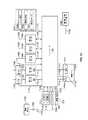
図2(b)は、ハンドル1103が機能セレクタモジュール1110を含むことを概略的に図示する。機能セレクタモジュール1110の付加的な詳細を以下で説明する。概して、機能セレクタモジュール1110は、複数の異なる位置の間で動くように、第1の回転型駆動軸1110aによって作動可能である。示された実施形態では、機能セレクタモジュール1110は、そのそれぞれが以下でさらに十分に説明される、4つの異なる機能的位置の間で第1の回転型駆動軸1110aによって作動可能である。機能セレクタモジュール1110は、異なる機能的位置のうちの各1つにおいて、機能セレクタモジュール1110が、外科用装置11の種々のドライバ88、98、201、202のうちの選択された1つとの第2の回転型駆動軸1110bの係合を引き起こすように、構成される。ドライバ88、98、201、202のうちの各1つは、第2の回転型駆動軸1110bとの係合および第2の回転型駆動軸1110bの動作時に、以下で説明されるように外科用装置11の特定の機能を果たすように構成される。 FIG. 2 (b) schematically illustrates that the
上記で説明されるように、図2(b)に示された実施形態では、ハンドル1103は、第1の回転型駆動軸1110aが第1の駆動ソケット654を介して第3の回転型駆動軸94に連結されることを可能にする、接続要素1104を含む。次に、第3の回転型駆動軸94は、第1のモータ96に連結されるか、または連結可能である。このように、第3の回転型駆動軸94、第1の駆動ソケット654、および第1の回転型駆動軸1110aを回転させる第1のモータ96の動作が、機能選択モジュール1110を作動させてもよい。 As described above, in the embodiment shown in FIG. 2 (b), the
また、図2(b)に示された実施形態では、ハンドル1103の接続要素1104は、第2の回転型駆動軸1110bが第2の駆動ソケット694を介して第4の回転型駆動軸102に連結されることを可能にしてもよい。次に、第4の回転型駆動軸102は、第2のモータ100に連結されるか、または連結可能である。このように、第4の回転型駆動軸102、第2の駆動ソケット694、および第2の回転型駆動軸1110bを回転させる第2のモータ100の動作が、機能選択モジュール1110の動作によって前もって選択された特定のドライバ機構を駆動してもよい。 Further, in the embodiment shown in FIG. 2B, the
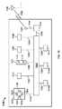
実施形態では、外科用装置11によって果たされてもよい第1の機能は、ハンドル1103に対して長手軸Dの周りで軸部分11bを回転させること、例えば、ハンドル1103に対して長手軸Dの周りで軸部分11bを回転させるように、ハンドル1103内の回転歯車を操作することである。この機能を果たすために、機能選択モジュール1110は、最初に、第1のモータ96による第1の回転型駆動軸1110aの作動によって(および、その間で係合された第3の回転型駆動軸94および第1の駆動ソケット654の回転によって)、第1の選択位置に配置されてもよい。一旦機能選択モジュール1110が第1の選択位置に配置されると、第2のモータ100の動作が回転ドライバ202を作動させるために、機能選択モジュール1110は、(その間で係合された第4の回転型駆動軸102および第2の駆動ソケット694を介して)回転ドライバ202を第2のモータ100と係合させる。本明細書で説明される実施形態では、回転ドライバ202は、(その間で係合された第4の回転型駆動軸102および第2の駆動ソケット694を介して)第2のモータ100によって作動されると、外科用装置11の他の操作を行うことに加えて、ハンドル1103に対して長手軸Dの周りで軸部分11bを回転させるように、例えば、ハンドル1103に対して長手軸Dの周りで軸部分11bを回転させるように、ハンドル1103内の回転歯車を操作するように動作してもよい。回転ドライバ202は、ハンドル1103に対して長手軸Dの周りで軸部分11bを回転させること、例えば、ハンドル1103に対して長手軸Dの周りで軸部分11bを回転させるように、ハンドル1103内の回転歯車を操作することが可能である、任意の種類の駆動機構を含んでもよい。回転ドライバ202は、ハンドル1103の遠位部分の中に位置してもよく、ハンドル1103に対して軸部分11bを動かす目的で軸部分11bに係合してもよい。本発明の実施形態例による、回転ドライバ202の付加的な詳細を、以下でさらに詳細に説明する。 In an embodiment, the first function that may be performed by the
実施形態では、外科用装置11によって果たされてもよい第2の機能は、軸部分11bに対してジョー部分11aを動かすこと、例えば、軸部分11bに対して軸Bの周りでジョー部分11aを枢動することである。この機能を果たすために、機能選択モジュール1110は、最初に、第1のモータ96による第1の回転型駆動軸1110aの作動によって(および、その間で係合された第3の回転型駆動軸94および第1の駆動ソケット654の回転によって)、第2の選択位置に配置されてもよい。一旦機能選択モジュール1110が第2の選択位置に配置されると、第2のモータ100の動作が関節運動ドライバ201を作動させるために、機能選択モジュール1110は、(その間で係合された第4の回転型駆動軸102および第2の駆動ソケット694を介して)関節運動ドライバ201を第2のモータ100と係合させる。本明細書で説明される実施形態では、関節運動ドライバ201は、(その間で係合された第4の回転型駆動軸102および第2の駆動ソケット694を介して)第2のモータ100によって作動されると、外科用装置11の他の操作を行うことに加えて、軸部分11bに対してジョー部分11aを動かすように、例えば、軸部分11bに対して軸Bの周りでジョー部分11aを枢動するように動作してもよい。関節運動ドライバ201は、例えば、軸部分11bに対して軸Bの周りでジョー部分11aを枢動するように、軸部分11bに対してジョー部分11aを動かすことが可能である、任意の種類の駆動機構を含んでもよい。関節運動ドライバ201は、軸部分11bの遠位部分1101aの中に位置してもよく、軸部分11bに対してジョー部分11aを動かす目的でジョー部分11aに係合してもよい。本発明の実施形態例による、関節運動ドライバ201の付加的な詳細を、以下でさらに詳細に説明する。 In an embodiment, a second function that may be performed by the
実施形態では、外科用装置11によって果たされてもよい第3の機能は、第2のジョー80に対して第1のジョー50を動かすこと、例えば、枢動または任意の他の考えられる相対運動によって開閉することである。この機能を果たすために、機能選択モジュール1110は、最初に、第1のモータ96による第1の回転型駆動軸1110aの作動によって(および、その間で係合された第3の回転型駆動軸94および第1の駆動ソケット654の回転によって)、第3の選択位置に配置されてもよい。一旦機能選択モジュール1110が第3の選択位置に配置されると、第2のモータ100の動作が締め付けドライバ88を作動させるように、機能選択モジュール1110は、(その間で係合された第4の回転型駆動軸102および第2の駆動ソケット694を介して)締め付けドライバ88を第2のモータ100と係合させる。本明細書で説明される実施形態では、締め付けドライバ88は、(その間で係合された第4の回転型駆動軸102および第2の駆動ソケット694を介して)第2のモータ100によって作動されると、外科用装置11の他の操作を行うことに加えて、第2のジョー80に対して第1のジョー50を動かす、例えば、開閉するように動作してもよい。締め付けドライバ88は、相互に対して第1のジョー50および第2のジョー80を動かすことが可能である、任意の種類の駆動機構を含んでもよい。締め付けドライバ88は、第2のジョー80の近位端80bの中に少なくとも部分的に位置してもよく、第2のジョー80に対して第1のジョー50を開閉するために、第1のジョー50の近位端50bに係合するよう第1のジョー50の近位端50bに接続されてもよい。本発明の実施形態例による、締め付けドライバ88の付加的な詳細を、以下でさらに詳細に説明する。 In an embodiment, a third function that may be performed by the
実施形態では、外科用装置11によって果たされてもよい第4の機能は、切断および/またはステープル固定要素を動かすこと、例えば、切断およびステープル固定要素104のネジ式駆動軸を旋回させることに等によって、組織片を通してステープル押込要素および/または切断刃を駆動することである。この機能を果たすために、機能選択モジュール1110は、最初に、第1のモータ96による第1の回転型駆動軸1110aの作動によって(および、その間で係合された第3の回転型駆動軸94および第1の駆動ソケット654の回転によって)、第4の選択位置に配置されてもよい。一旦機能選択モジュール1110が第4の選択位置に配置されると、第2のモータ100の動作が第2のドライバ88を作動させるように、機能選択モジュール1110は、(その間で係合された第4の回転型駆動軸102および第2の駆動ソケット694を介して)発射ドライバ98を第2のモータ100と係合させる。本明細書で説明される実施形態では、第2のドライバ88は、(その間で係合された第4の回転型駆動軸102および第2の駆動ソケット694を介して)第2のモータ100によって作動されると、外科用装置11の他の操作を行うことに加えて、切断および/またはステープル固定要素を動かすように、例えば、組織片を通してステープル押込要素および/または切断刃を駆動するように動作してもよい。発射ドライバ98は、切断および/またはステープル固定要素を動かすこと、例えば、組織片を通してステープル押込要素および/または切断刃を駆動することが可能である、任意の種類の駆動機構を含んでもよい。発射ドライバ98は、第1のジョー50と第2のジョー80との間に配置される組織片を切断する、および/またはステープルで固定するよう、第2のジョー80の近位端80bと遠位端80aとの間に位置してもよい。本発明の実施形態例による、発射ドライバ98の付加的な詳細を、以下でさらに詳細に説明する。 In an embodiment, a fourth function that may be performed by the
2つの駆動ソケット、例えば、第1の駆動ソケット654および第2の駆動ソケット694、ならびに2つの対応する駆動軸、例えば、第1の駆動軸94および第2の駆動軸102は、外科用装置11の一部であるとして図示され、例えば、他の構成要素に対して外科用装置11のある構成要素を動かし、配置する目的、および/または組織片を締め付け、切断し、ステープで固定する目的のものであるとして図示されているが、任意の好適な数の駆動ソケットおよび駆動軸を提供することが可能であると認識されたい。例えば、外科用装置11の上記の機能を果たすように、単一の駆動軸、または2つより多い駆動軸が提供されてもよい。 Two drive sockets, such as a first drive socket 654 and a
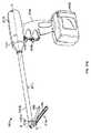
駆動軸、例えば、第1および第2の回転型駆動軸94および102ならびに任意の他の駆動軸は、図2(a)に図示された可撓駆動軸1620等の可撓駆動軸内に収納されてもよい。他の種類の可撓駆動軸も採用されてもよい。例えば、駆動軸は、その全体で参照することにより本明細書に明示的に組み込まれる、「Flexible Shaft foran Electro−Mechanical Surgical Device」と題された2006年7月27日出願の米国仮特許出願第60/703,227号で説明および図示されている種類の可撓駆動軸内に収納されてもよい。 The drive shaft, for example, the first and second
図2(b)を参照すると、外科用装置11はまた、メモリモジュール6041を含んでもよい。実施形態では、メモリモジュール6041は、切断およびステープル固定要素104に接続されるか、またはそれと一体化している。メモリモジュール6041は、データ転送ケーブル1278によってデータコネクタ1272に接続される。これらの構成要素の付加的な特徴を、例えば、図3(f)および7に関連して説明する。 With reference to FIG. 2 (b), the
さらに、図2(b)は、接続要素1104も図示する。接続要素1104は、可撓駆動軸1620の相補迅速接続要素1664に係合する迅速接続スロット713aを有する、迅速接続スリーブ713を含んでもよく、それは以下でさらに詳細に説明される。迅速接続スリーブ713の迅速接続スロット713aの中で可撓駆動軸1620の迅速接続要素1664を保持するために、接続要素1104はまた、バネを含んでもよい。 In addition, FIG. 2 (b) also illustrates a connecting
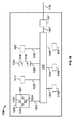
また、第1および第2の回転型駆動軸1110aおよび1110bを駆動するために採用されるモータは、外科用装置11と一体化してもよいことを認識されたい。例えば、図2(c)は、本発明の別の実施形態例による、外科用装置11の代替配設を図示する概略図である。この実施形態では、第1および第2の回転型駆動軸1110aおよび1110bが、それぞれ第1および第2のモータ961、1001に接続されるように、第1のモータ961および第2のモータ1001は、ハンドル1103内で配設される。 It should also be appreciated that the motor employed to drive the first and second
本発明の実施形態例によれば、外科用装置11は、図2(a)に図示されたモータシステムを有する電気機械ドライバ構成要素1610等の電気機械外科用システムの付属部品として構成されてもよく、または電気機械外科用システムと一体化してもよい。この実施形態例では、任意の適切な数のモータが提供されてもよく、モータは、バッテリ電力、線電流、DC電力供給部、電子制御式DC電力供給部等を介して動作してもよいことを理解されたい。モータは、DC電力供給部に接続されてもよく、次に、DC電力供給部は、線電流に接続され、モータに動作電流を供給することも理解されたい。別の実施形態例では、外科用装置は、機械的ドライバシステムの付属部品として構成されてもよく、または機械的ドライバシステムと一体化してもよい。 According to an example embodiment of the present invention, the
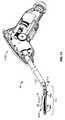
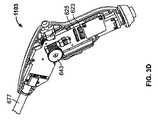
図3(a)は、本発明の実施形態による外科用装置11の斜視図である。上記で説明されるように、図3(a)−3(e)は、ハンドル1103に対して、およびハンドル1103の長手軸の周りで軸部分11bを回転させるため、軸部分11bに対してジョー部分11aを動かす、例えば、関節運動させるため、第2のジョー80に対して第1のジョー50を動かす、例えば、開放または閉鎖するため、およびステープル固定および切断カートリッジを発射するために、2つの駆動軸が採用されるように構成される、本発明の実施形態を図示する。図3(a)に示された位置では、ジョー部分11aは、軸部分11bに対して約60度の角度で配置されている。ジョー部分11aは、患者に行われる切開に従って、および締め付けられ、切断され、および/またはステープルで固定されることが所望される組織の位置に従って、適切に配置されてもよい。 FIG. 3 (a) is a perspective view of the
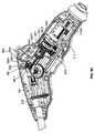
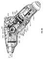
上記のように、図3(b)は、本発明の実施形態による、外科用装置のハンドル1103を図示する、部分的断面の側面図である。図3(c)は、図3(b)に図示された実施形態による、外科用装置のハンドルの付加的な特徴を図示する、部分的断面の側面斜視図である。図3(d)および3(e)は、本発明の実施形態例による、外科用装置のハンドルのなおもさらなる特徴を図示する、部分的断面の側面斜視図である。 As described above, FIG. 3 (b) is a partial cross-sectional side view illustrating a
ここで図3(b)を参照すると、ハンドル1103が、ハンドル1103の近位端から内向きに延在する第1の回転型駆動軸1110aを含むことが図示されている。第1の回転型駆動軸1110aは、セレクタ軸601の近位端が配設される長手方向に配設された穴を有する。有利なことには、第1の回転型駆動軸1110aの長手方向に配設された穴およびセレクタ軸601の近位端は、係合されると、第1の回転型駆動軸1110aの回転がセレクタ軸601の回転を引き起こすように、対応して寸法設定および成形される。加えて、セレクタ軸601の近位端は、バネ603を通して挿入され、セレクタ軸601の長手方向停止部と第1の回転型駆動軸1110aとの間で適所に維持される。バネ603は、近位方向に第1の回転型駆動軸1110aを付勢するように機能する。 Referring now to FIG. 3 (b), the
セレクタ軸601の最遠位端は、ハンドル1103の固定内壁605の開口内で回転可能に載置され、ハンドルの固定内壁605は、セレクタ軸601の長手軸と垂直である。セレクタ軸601はまた、その最遠位端に隣接する長さに沿って、ネジ式部分607も含む。機能セレクタブロック609は、それを通って長手方向に延在する、ネジ穴を有する。セレクタ軸601のネジ式部分607は、機能セレクタブロック609がその上に載置されるように、機能セレクタブロック609のネジ穴を通って延在する。機能セレクタブロック609は、セレクタ軸601の回転時に、機能セレクタブロック609のネジ穴の内側のセレクタ軸601のネジ式部分607のネジ式係合が、機能セレクタブロック609をセレクタ軸601に沿って遠位および近位に動かすように、ハンドルの内面に合わせられる。 The most distal end of the
図3(b)はまた、ハンドル1103が、ハンドル1103の近位端から内向きに延在する第2の回転型駆動軸1110bを含むことも図示する。第2の回転型駆動軸1110bは、その中に機能軸611の近位端が配設される長手方向に配設された穴を有する。有利なことには、第2の回転型駆動軸1110bの長手方向に配設された穴および機能軸611の近位端は、係合されると、第2の回転型駆動軸1110bの回転が機能軸611の回転を引き起こすように、対応して寸法設定および成形される。加えて、機能軸611の近位端は、バネ613を通して挿入され、機能軸611の長手方向停止部と第2の回転型駆動軸1110bとの間で適所にて維持される。バネ613は、近位方向に第2の回転型駆動軸1110bを付勢するように機能する。 FIG. 3 (b) also illustrates that the
機能軸611の最遠位端は、ハンドルの固定内壁615の開口内で回転可能に載置され、ハンドル1103の固定内壁615は、機能軸611の長手軸と垂直である。機能軸611はまた、その最遠位端に隣接する長さに沿って、発射平歯車617も含む。発射平歯車617に対して近位の位置で機能軸611に沿って位置するのは、入力平歯車619である。発射平歯車617および入力平歯車619はそれぞれ、それぞれの外周の歯車の歯6171、6191を有する。また、ハンドルの固定内壁615の開口内で回転可能に載置されるのは、2次発射平歯車618である。2次平歯車618は、発射平歯車619の外周の歯車の歯6191と咬み合って係合される、外周の歯車の歯6181を有する。 The most distal end of the
機能セレクタブロック609から遠位に延在するのは、歯車軸621である。歯車軸621に沿った様々な長手方向位置に配設されるのは、種々の歯車である。例えば、機能セレクタブロック609に最も近く隣接している歯車軸621に沿った長手方向位置には、回転平歯車623がある。回転平歯車623は、外周の歯車の歯6231を含む。外周の歯車の歯6231は、入力平歯車619の外周の歯車の歯6191に係合する。実施形態では、回転平歯車623および入力平歯車619は、相互に対して4:1の歯車比を提供する。当然ながら、任意の好適な歯車比が採用されてもよいことを認識されたい。また、回転平歯車623に対して遠位にある歯車軸621に沿った長手方向位置には、発射平歯車625がある。発射平歯車625は、外周の歯車の歯6251を含む。発射平歯車625の外周の歯車の歯6251は、発射平歯車617の外周の歯車の歯6171に係合する。加えて、発射平歯車625に対して遠位にある歯車軸621に沿った長手方向位置には、締め付け平歯車627がある。締め付け平歯車627は、外周の歯車の歯6271を含む。締め付け平歯車627に対して遠位にある歯車軸621に沿った長手方向位置には、関節運動平歯車629がある。関節運動平歯車629は、外周の歯車の歯6291を含む。なおもさらに、関節運動平歯車629に対して遠位にある歯車軸621に沿った長手方向位置には、回転平歯車631がある。回転平歯車631は、外周の歯車の歯6311を含む。 Extending distally from the
ハンドル1103はまた、回転歯車軸633も含む。回転歯車軸633の近位端は、ハンドル1103の固定内壁635の開口内で回転可能に載置され、ハンドル1103の固定内壁635は、回転歯車軸633の長手軸と略垂直である。回転歯車軸633の遠位端は、ハンドル1103の固定内壁637の開口内で回転可能に載置され、ハンドル1103の固定内壁637も、回転歯車軸633の長手軸と略垂直である。回転歯車軸633は、その近位端に隣接した長さに沿って、回転平歯車639を含む。回転平歯車639は、外周の歯車の歯6391を有する。回転歯車軸633はまた、その遠位端に隣接した長さに沿って、回転ウォーム歯車641も含む。回転ウォーム歯車641は、外周のウォーム歯車の歯6411を有する。 The
回転歯車643は、ハンドル1103の固定内壁645に回転可能に載置される。有利なことには、回転歯車643は、回転歯車軸633の長手軸と垂直である枢動軸の周りで回転可能に載置される。回転歯車643は、回転ウォーム歯車641の外周のウォーム歯車の歯6411と咬み合って係合される、外周の歯車の歯6431を有する。実施形態では、回転歯車643および回転ウォーム歯車641は、相互に対して45:1の歯車比を提供する。当然ながら、任意の好適な歯車比が採用されてもよいことを認識されたい。回転歯車643の表面に載置され、それとともに回転するように構成されるのは、回転マイタ歯車644である。回転マイタ歯車644は、マイタ歯車の歯6441を有する。 The
ハンドル1103はまた、第2の回転歯車軸665も含む。第2の回転歯車軸665は、第2の回転歯車軸665が長手方向および回転可能に維持されるチャネル667によって、ハンドル1103内に維持される。第2の回転歯車軸665の近位端は、回転マイタ歯車669を含む。回転マイタ歯車669は、マイタ歯車の歯6691を有する。回転マイタ歯車669のマイタ歯車の歯6691は、マイタ歯車644のマイタ歯車の歯6441と咬み合って係合される。 The
第2の回転歯車軸665の遠位端は、ハンドル1103の固定内壁671の開口内で回転可能に載置され、ハンドル1103の固定内壁671は、第2の締め付け歯車軸665の長手軸と略垂直である。第2の回転歯車軸665はまた、その遠位端に隣接した長さに沿って、回転平歯車673も含む。回転平歯車673は、外周の歯車の歯6731を有する。 The distal end of the second
ハンドル1103の最遠位端における開口675内に載置されるのは、回転管677である。長手方向停止部は、開口675内で長手方向に回転管677を維持する。回転管677の遠位端は、管筐体523まで延在する。回転管677の近位端は、回転管平歯車679を含む。回転管平歯車679は、外周の歯車の歯6791を有する。回転管平歯車679の外周の歯車の歯6791は、回転平歯車673の外周の歯車の歯6731と咬み合って係合される。実施形態では、回転平歯車673および回転管平歯車679は、相互に対して1.4:1の歯車比を提供する。当然ながら、任意の好適な歯車比が採用されてもよいことを認識されたい。 Mounted in the
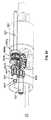
図5(b)は、図3(b)で提供された側面図とは反対側の部分的断面の側面斜視図である。図5(b)は、図3(b)の図から隠されている、ハンドル1103の付加的な構成要素を図示する。ここで図5(b)を参照すると、関節運動歯車軸685が示されている。関節運動歯車軸685の近位端は、ハンドル1103の固定内壁(透視で示される)の開口内で回転可能に載置され、ハンドル1103の固定内壁は、関節運動歯車軸685の長手軸と略垂直である。関節運動歯車軸685の遠位端は、ハンドル1103の別の固定内壁(同様に透視で示される)の開口内で回転可能に載置され、このハンドル1103の固定内壁も、関節運動歯車軸685の長手軸と略垂直である。関節運動歯車軸685は、その近位端に隣接した長さに沿って、関節運動平歯車687を含む。関節運動平歯車687は、外周の歯車の歯6871を有する。関節運動平歯車687の外周の歯車の歯6871は、関節運動平歯車629の外周の歯車の歯6291と咬み合って係合される。関節運動歯車軸685はまた、その遠位端に隣接した長さに沿って、関節運動ウォーム歯車689も含む。関節運動ウォーム歯車689は、外周のウォーム歯車の歯6891を有する。 FIG. 5 (b) is a side perspective view of a partial cross-section opposite to the side view provided in FIG. 3 (b). FIG. 5 (b) illustrates additional components of the
関節運動歯車691は、ハンドル1103の固定内壁693に回転可能に載置される。有利なことには、関節運動歯車691は、関節運動歯車軸685の長手軸と垂直である枢動軸の周りで回転可能に載置される。関節運動歯車691は、関節運動ウォーム歯車689の外周のウォーム歯車の歯6891と咬み合って係合される、外周の歯車の歯6911を有する。実施形態では、関節運動歯車691および関節運動ウォーム歯車689は、相互に対して11.25:1の歯車比を提供する。当然ながら、任意の好適な歯車比が採用されてもよいことを認識されたい。 The articulation gear 691 is rotatably mounted on the fixed
再度、図3(b)を参照すると、関節運動機能に貢献するハンドル1103の付加的な特徴が示されている。例えば、関節運動歯車691の表面に載置され、それとともに回転するように構成されるのは、第1の関節運動マイタ歯車692である。第1の関節運動マイタ歯車692は、マイタ歯車の歯6921を有する。 Referring again to FIG. 3 (b), additional features of the
ハンドル1103はまた、第2の関節運動歯車軸693も含む。第2の関節運動歯車軸693は、チャネル694によってハンドル1103内で回転可能に保持される。第2の関節運動歯車軸693の近位端は、ネジ式棒695を形成する。ネジ式棒695の上に載置されるのは、関節運動マイタ歯車支持材697によってハンドル696内で載置される、第2の関節運動マイタ歯車696である。第2の関節運動マイタ歯車696は、マイタ歯車の歯6961を有する。第2の関節運動マイタ歯車696のマイタ歯車の歯6961は、第1の関節運動マイタ歯車692のマイタ歯車の歯6921と咬み合って係合される。関節運動歯車支持材697は、ハンドル1103内で第2の関節運動マイタ歯車696の長手方向および半径方向位置を維持する一方で、第2の関節運動マイタ歯車696がその長手軸の周りで回転することを可能にする。第2の関節運動マイタ歯車696は、長手方向に配設されたネジ穴を画定し、第2の関節運動歯車軸693のネジ式棒695は、第2の関節運動マイタ歯車696の長手方向に配設されたネジ穴に係合する。 The
第2の関節運動歯車軸693の遠位端は、回転管平歯車679の中心領域を通る長手方向に画定された開口部を通って延在し、最終的に(図4(a)に示されるような)関節運動軸525を形成するよう、ハンドル1103の開口675において回転管677を通過する。第2の関節運動歯車軸693のネジ式棒695と第2の関節運動マイタ歯車696の長手方向に配設されたネジ穴との間のネジ式係合により、第2の関節運動マイタ歯車696の回転は、ハンドル1103に対する第2の関節運動歯車軸693の遠位または近位方向に選択的運動を引き起こす。 The distal end of the second
図3(b)を参照すると、ハンドル1103はまた、締め付け歯車軸651も含む。締め付け歯車軸651の近位端は、ハンドル1103の固定内壁653の開口内で回転可能に載置され、ハンドル1103の固定内壁653は、締め付け歯車軸651の長手軸と略垂直である。締め付け歯車軸651は、その遠位端に隣接した長さに沿って、締め付け平歯車655を含む。締め付け平歯車655は、外周の歯車の歯6551を有する。締め付け歯車軸651はまた、その遠位端において、第1の締め付けマイタ歯車657も含む。第1の締め付けマイタ歯車657は、マイタ歯車の歯6571を有する。 Referring to FIG. 3 (b), the
第2の締め付けマイタ歯車659は、ハンドル1103の固定内壁663に回転可能に載置される。有利なことには、第2の締め付けマイタ歯車659は、締め付け歯車軸651の長手軸と垂直である枢動軸の周りで回転可能に載置される。第2の締め付けマイタ歯車659は、第1の締め付けマイタ歯車657のマイタ歯車の歯6571と咬み合って係合される、マイタ歯車の歯6591を有する。 The second
また、ハンドル1103は、第2の締め付け歯車軸681を含む。第2の締め付け歯車軸681の近位端は、第3の締め付けマイタ歯車661を含む。第3の締め付けマイタ歯車661は、第2の締め付けマイタ歯車659のマイタ歯車の歯6591と咬み合って係合される、マイタ歯車の歯6611を有する。第2の締め付け歯車軸681の遠位端は、回転管平歯車679の中心領域を通る長手方向に画定された開口部を通って延在し、最終的に(図4(a)に示されるような)締め付け軸527を形成するよう、ハンドル1103の開口675において回転管677を通過する。 The
図3(b)を参照すると、ハンドル1103はまた、発射歯車軸604も含む。その近位端に隣接して、発射歯車軸604は、ハンドル1103の固定内部支持材606の開口内で回転可能に載置され、ハンドル1103の固定内部支持材604は、その中に機能軸611の遠位端が回転可能に載置される、固定内壁606を、その遠位表面として含む。発射歯車軸604は、その近位端において、発射平歯車608を含む。発射平歯車608は、外周の歯車の歯6081を有する。発射平歯車608の外周の歯車の歯6081は、発射平歯車617の外周の歯車の歯6171と咬み合って係合される。 Referring to FIG. 3 (b), the
図5(d)は、図3(b)で提供された側面図とは反対側の部分的断面の側面斜視図を図示する。図5(d)は、図3(b)の図から隠されている、ハンドル1103の付加的な構成要素を図示する。ここで図5(d)を参照すると、発射歯車軸604は、その遠位端において、第1の発射マイタ歯車610を含む。第1の発射マイタ歯車610は、マイタ歯車の歯6101を有する。 FIG. 5 (d) illustrates a side perspective view of a partial cross-section opposite to the side view provided in FIG. 3 (b). FIG. 5 (d) illustrates additional components of the
第2の発射マイタ歯車612は、ハンドル1103の固定内壁616に回転可能に載置される。有利なことには、第2の発射マイタ歯車612は、発射歯車軸604の長手軸と垂直である枢動軸の周りで回転可能に載置される。第2の発射マイタ歯車612は、第1の発射マイタ歯車610のマイタ歯車の歯6101と咬み合って係合される、マイタ歯車の歯6121を有する。 The second
また、ハンドル1103は、第2の発射歯車軸618を含む。第2の発射歯車軸618の近位端は、第3の発射マイタ歯車614を含む。第3の発射マイタ歯車614は、第2の発射マイタ歯車612のマイタ歯車の歯6121と咬み合って係合される、マイタ歯車の歯6141を有する。第2の発射歯車軸618の遠位端は、回転管平歯車679の中心領域を通る長手方向に画定された開口部を通って延在し、最終的に(図4(a)に示されるような)発射軸529を形成するよう、ハンドル1103の開口675において回転管677を通過する。 The
図3(b)はまた、本発明の実施形態によれば、外科用装置11が光機能センサ3001、3002、3003、および3004を含んでもよいことも図示する。これらの光センサ3001、3002、3003、および3004はそれぞれ、壁3005の各穴から出る光を提供する、ダイオード、例えば、LEDを含んでもよい。セレクタ軸601のネジ式部分607を介した機能セレクタブロック609の運動は、センサ3001、3002、3003、および3004のダイオードのうちの1つからの光の透過を選択的に遮断する。この光の透過の遮断は、機能セレクタブロック609が4つの上記の機能的位置のうちのどの1つにあるのかを外科用装置11が判定し、したがって、それに応じて外科用装置11の操作を制御することを可能にする。言い換えれば、機能セレクタブロック609の位置に応じて、光センサ3001、3002、3003、および3004のうちの種々のセンサを往復する、対応する信号が遮断され、それにより、外科用装置11が、4つの上記の機能的位置、例えば、相互に対するジョーの回転、関節運動、開閉、ならびに切断および/またはステープル固定機構の発射のうちの1つに順調に配置されると、好適なコントローラに指標を提供する。 FIG. 3 (b) also illustrates that the
図3(b)はまた、本発明の実施形態によれば、外科用装置11が回転/関節運動制御装置3006を含んでもよいことも図示する。実施形態では、回転/関節運動制御装置3006は、例えば、ハンドル1103の頂面上で好適に配置され、操作者がハンドル1103を担持している時に操作者の親指によって作動可能となるよう寸法設定される、ジョイスティック型装置であってもよい。また、図3(b)は、本発明の実施形態によれば、外科用装置11が開放/閉鎖/発射制御装置3007を含んでもよいことも図示する。実施形態では、開放/閉鎖/発射制御装置3007は、例えば、ハンドル1103の底面上で好適に配置され、操作者がハンドル1103を担持している時に操作者の人差し指によって作動可能となるよう寸法設定される、トリガ型装置であってもよい。回転/関節運動制御装置3006および開放/閉鎖/発射制御装置3007の操作を、以下でさらに詳細に説明する。 FIG. 3 (b) also illustrates that the
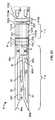
図3(f)、4(a)−4(c)および4(d)は、ハンドル1103に対して遠位にある外科用装置の構成要素をまとめて図示する。例えば、図3(f)は、本発明の実施形態による、組み立てられた時の外科用装置11の遠位アセンブリの側面斜視図である。図4(a)は、図3(f)に図示された実施形態による、この遠位アセンブリの近位セクションを図示する分解斜視図である。 3 (f), 4 (a) -4 (c) and 4 (d) collectively illustrate the components of the surgical device distal to the
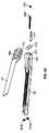
例えば、図4(a)は、その各1つが一対のネジ山付きネジ501a、501bのそれぞれ1つを受容するように構成される、一対の長手方向に配設された開口を有する、近位枢動筐体503を図示する。近位枢動筐体503はまた、その各1つが一対の玉軸受507a、507bのそれぞれ1つに挿入されるように構成される、一対の入力傘歯車505a、505bも収納する。近位枢動筐体503に対して近位に配設されるのは、管筐体523である。 For example, FIG. 4 (a) shows a proximal having a pair of longitudinally disposed openings, each one of which is configured to receive a respective one of a pair of threaded
一対の入力傘歯車505a、505bのうちの各1つは、その近位端において、長手方向に配設された開口を含む。第1の玉軸受507aに対して近位に、ベベルスラストブロック509が配設される。ベベルスラストブロック509は、それを通る長手方向に配設された穴を有する。締め付け軸527の遠位端は、管筐体523の長手方向に配設された開口部を通り、ベベルスラストブロック509の長手方向に配設された穴を通り、玉軸受507aの長手方向に配設された穴を通って延在するように、および入力傘歯車505aの近位端における長手方向に配設された開口に係合するように構成される。有利なことには、締め付け軸527の遠位端、および入力傘歯車505aの近位端における長手方向に配設された開口は、係合されると、締め付け軸527の回転が入力傘歯車505aの回転を引き起こすように、対応して寸法設定および成形される。 Each one of the pair of
また、第2の玉軸受507bに対して近位に、ベベルスラストブロック511も配設される。ベベルスラストブロック511の外周表面は、その中に着座した関節運動スラストピン513を有するように構成される、円形の切り欠き5111を含む。近位関節運動歯車515は、その中へ関節運動スラストピン513が下から挿入されるように構成される、中央開口を有する。ベベルスラストブロック511はまた、それを通る長手方向に配設された穴も有する。発射軸529の遠位端は、管筐体523の長手方向に配設された開口部を通り、ベベルスラストブロック511の長手方向に配設された穴を通って延在するように、および入力傘歯車505bの近位端における長手方向に配設された開口に係合するように構成される。有利なことには、発射軸529の遠位端、および入力傘歯車505bの近位端における長手方向に配設された開口は、係合されると、発射軸529の回転が入力傘歯車505bの回転を引き起こすように、対応して寸法設定および成形される。 A
管筐体503は、その遠位端において一対の垂直に整列した穴5031を有する。加えて、管筐体503は、近位関節運動歯車515の一部分を受容するように、その遠位端において好適に成形されたスロットを有する。下から近位関節運動歯車515の中央開口に挿入されるように構成される、関節運動スラストピン513に加えて、関節運動歯車515の中央開口も、上からラック歯車519を受容するよう、好適に寸法設定および成形される。ラック歯車519の歯は、ラック517に係合するように構成される。ラック517は、管筐体513における対応して成形され長手方向に配設された開口部を通って延在する。ラック517の近位端における開口は、関節運動軸525の遠位端を受容するように構成され、クリップ521によってそれに対して適所で維持される。
上記で説明されるように、図4(b)は、図3(f)に図示された実施形態による、遠位アセンブリの関節運動アセンブリセクションを図示する分解斜視図である。図4(b)は、発射入力傘歯車533に係合するように構成される、発射バネ531を図示する。発射入力傘歯車533は、カートリッジ筐体連結部535の長手方向に配設された開口部を通って延在するように構成され、その近位端において傘歯車5331を有する。加えて、締め付けネジ軸537も、カートリッジ筐体連結部535の長手方向に配設された開口部を通って延在する。締め付けネジ軸537に対して近位に、外側遊び歯車539が配設される。外側遊び歯車539は、それを通って締め付けネジ軸537の近位端が延在するように構成される、長手方向に配設された穴を含む。外側遊び歯車539はまた、外周の歯車の歯も含む。 As described above, FIG. 4 (b) is an exploded perspective view illustrating the articulation assembly section of the distal assembly, according to the embodiment illustrated in FIG. 3 (f). FIG. 4 (b) illustrates a
図4(b)はまた、複合かさ/平歯車構成要素541も図示する。複合かさ/平歯車構成要素541は、カートリッジ筐体連結部535における対応して寸法設定および成形された開口内で、その遠位端5411において回転可能に載置されるように構成される。加えて、複合かさ/平歯車構成要素541は、その中間領域に沿って、外周の歯を有する平歯車5412を含む。外側遊び歯車539の外周の歯は、複合かさ/平歯車構成要素541の平歯車5412の外周の歯と咬み合って係合するように構成される。また、複合かさ/平歯車構成要素541は、その近位端において、傘歯車5413も含む。 FIG. 4 (b) also illustrates a composite bevel /
図4(b)はまた、遠位枢動筐体543も図示する。遠位枢動筐体543は、その近位端において一対の垂直に整列した穴5431を有する。また、複合かさ/平歯車構成要素541の遠位端における傘歯車5413、外側遊び歯車539、および発射入力ベベル構成要素533の遠位端における傘歯車5331はそれぞれ、遠位枢動筐体543の各長手方向に配設された開口内に存在するように構成される。加えて、遠位枢動筐体543は、一対の長手方向に配設された開口を含み、その各1つは、一対のネジ山付きネジ545a、545bのそれぞれ1つを受容するように構成される。 FIG. 4 (b) also illustrates the
遠位枢動筐体543は、遠位関節運動歯車547の一部分を受容するように、その遠位端において好適に成形されたスロットを有する。遠位関節運動歯車547は、中央開口と、遠位関節運動歯車547の少なくとも一部分の周囲に延在する外周の歯車の歯とを画定する。一対の遊び傘歯車549a、549bが、遠位関節運動歯車の各対向上面および下面の上に配設される。一対の遊び傘歯車549a、549bのうちの各1つは、遠位関節運動歯車547の中央に配置された開口と整列されるように構成される、中央に配置された開口を含む。ヒンジピン551は、近位枢動筐体503の遠位端における一対の垂直に整列した穴5031の内側、遠位枢動筐体543の近位端における一対の垂直に整列した穴5431の内側、一対の遊び傘歯車549a、549bのうちの各1つの中央に配置された開口の内側、および遠位関節運動歯車547の中央に配置された開口の内側で受容されるように構成される。 The
上記で説明されるように、図4(c)は、図3(f)に図示された実施形態による、遠位アセンブリの遠位セクションを図示する分解斜視図である。図4(c)は、第1のジョー50および第2のジョー80を図示する。第1のジョー50の近位部分は、第1のジョー50の近位部分の側面に沿って延在する、第1のスロット552を含む。また、第1のジョー50の近位部分は、第1のジョー50の近位部分の頂面に沿って延在する、第2のスロット556も含む。加えて、第2のジョーの近位部分が第1のジョー50の近位部分内に存在するように、第2のジョー80の近位部分は、第2のジョーの近位部分が第1のジョー50の第2のスロット556内に嵌合してもよいように、寸法設定および成形される。加えて、第2のジョーの近位部分は、スロット554を含む。 As described above, FIG. 4 (c) is an exploded perspective view illustrating the distal section of the distal assembly, according to the embodiment illustrated in FIG. 3 (f). FIG. 4 (c) illustrates the
内側軸555は、第1のジョー50の第1のスロット552および第2のジョー80のスロット554内に嵌合するように、およびそれらに対して略遠位および近位方向に可動であるように構成される。内側軸555は、第1の円周表面から反対側の円周表面まで、それを通って半径方向に延在する、ネジ穴を含む。締め付けネジ559は、第2のジョー80の近位端の長手方向に配設された開口内で受容されるように構成される。内側軸555のネジ穴は、締め付けネジ559のネジ式遠位端を受容するように構成される。締め付けネジ559はまた、その近位端において、締め付けネジ軸537の相応じて寸法設定および成形された遠位端を受容するよう好適に寸法設定および成形される、長手方向に配設された開口も含む。 The
図4(c)はまた、発射軸557も図示する。発射軸557の遠位端は、例えば、第2のジョー80の近位端から遠位端まで延在する切断およびステープル固定要素104のネジ式駆動軸(図示せず)の相応じて寸法設定および成形された近位端を受容するよう、好適に寸法設定および成形される、長手方向に配設された開口を含む。発射軸557の近位端は、その遠位端より小さい直径を有し、バネ531内で長手方向に受容されるように構成される。また、発射軸557の近位端は、発射入力傘歯車533の遠位端における、対応して寸法設定および成形され、長手方向に配設された穴の内側で受容されることが好適である、断面サイズおよび形状を有する。一対のナット563a、563bは、ネジ山付きネジ545a、545bのそれぞれ1つに係合するように構成され、そのそれぞれは、遠位枢動筐体543の一対の長手方向に配設された開口のそれぞれ1つを通り、第2のジョー80の一対の長手方向に配設された開口のそれぞれ1つを通って延在する。 FIG. 4 (c) also illustrates firing
図4(d)は、図3(f)に図示された実施形態による、外科用装置11が関節運動するように構成される領域の付加的な詳細を示す、組み立てられた時の外科用装置11の遠位アセンブリの部分的断面の側面斜視図である。例えば、図4(d)は、近位枢動筐体503の垂直に整列した開口5031および遠位枢動筐体543の垂直に整列した開口5431を通って延在するヒンジピン551によって、遠位枢動筐体543(透視で図示)に接続される近位枢動筐体503(同様に透視で図示)を図示する。ヒンジピン551はまた、遠位関節運動歯車547の中心開口を通り、遠位関節運動歯車547の各対向上面および下面の上に配設される、一対の遊び傘歯車549a、549bの中央に配置された開口を通って挿入される。 FIG. 4 (d) shows the surgical device when assembled, showing additional details of the region in which the
締め付け軸527は、遠位に延在し、管筐体523の長手方向に配設された開口部を通り、ベベルスラストブロック509および玉軸受507aの長手方向に配設された穴を通って延在し、入力傘歯車505aの近位端における長手方向に配設された開口に係合する。入力傘歯車505aの歯車の歯は、上遊び傘歯車549aの歯車の歯と咬み合って係合される。また、複合かさ/平歯車構成要素541の傘歯車5413の歯車の歯も、上遊び傘歯車549aの歯車の歯と咬み合って係合される。複合かさ/平歯車構成要素541は、その遠位端5411において回転可能に載置される。加えて、複合かさ/平歯車構成要素541の平歯車5412の外周の歯は、締め付けネジ軸537上に載置される外側遊び歯車539の外周の歯と咬み合って係合される。 The
発射軸529は、遠位に延在し、管筐体523の長手方向に配設された開口部を通り、ベベルスラストブロック511および玉軸受507bの長手方向に配設された穴を通って延在し、入力傘歯車505bの近位端における長手方向に配設された開口に係合する。入力傘歯車505bの歯車の歯は、下遊び傘歯車549bの歯車の歯と咬み合って係合される。また、発射入力傘歯車533の傘歯車5331の歯車の歯も、下遊び傘歯車549bの歯車の歯と咬み合って係合される。発射入力傘歯車533は、発射軸557へと遠位に延在する。 The firing
関節運動軸525も、遠位に延在し、管筐体523の長手方向に配設された開口部を通って延在する。関節運動軸525の遠位端に、クリップ521によってラック537が載置され、その歯は、ラック歯車519の外周の歯と係合される。ラック歯車519は、近位関節運動歯車515の上面の上に配置され、関節運動スラストピン513の上に回転可能に載置される。近位関節運動歯車515の外周の歯車の歯は、遠位関節運動歯車547の外周の歯車の歯と咬み合って係合される。遠位関節運動歯車547は、遠位枢動筐体543に対して回転固定される。 The
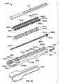
上記で説明されるように、外科用装置11はまた、切断およびステープル固定要素104を含んでもよい。実施形態では、ステープルおよび切断要素104は、ステープルカートリッジである。図4(e)は、交換可能ステープルカートリッジ2600の分解斜視図である。交換可能ステープルカートリッジ2600は、例えば、図3(a)−3(e)に図示された本発明の実施形態例で、切断およびステープル固定要素104として採用されてもよい、1つの種類のステープル固定/切断配設である。交換可能ステープルカートリッジ2600は、ステープルトレイ2604を含む。ステープルトレイ2604は、その近位端2604dにおいて、メモリモジュール6041がメモリモジュール保持器6042によって保持される、スロット2604iを有する。例えば、そのそれぞれがその全体で参照することにより本明細書に明示的に組み込まれる、現在は2004年9月21日に米国特許第6,793,652号として発行されている、2000年11月28日に出願された米国特許出願第09/723,715号、2001年4月17日に出願された米国特許出願第09/836,781号、2001年6月22日に出願された米国特許出願第09/887,789号、および2002年3月15日に出願された米国特許出願第10/099,634号で説明されているように、メモリモジュール6041は、情報を記憶してもよい。ウェッジドライバ2605は、ステープルトレイ2604の中央チャネル2604eを通って回転可能に配置されるように構成される。具体的には、ウェッジドライバ2605は、ステープルトレイ2604の遠位開口604a内で回転可能に載置されるように構成される、遠位端2605aを有する。ウェッジドライバ2605はまた、雄ネジ領域2605bと、ステープルトレイ2604の近位端2604bの近位開口2604bを通って回転可能に延在する非ネジ式部分2605cと、締め付けネジ559の遠位端を受容するための、最近位端における近位に対面する開口部2605dとを含む。近位に対面する開口部2605dおよび締め付けネジ559の遠位端は、締め付けネジ559の遠位端が、近位に対面する開口部2605d内で受容される、例えば、挿入されると、相互に対する非回転型連結のために適合される。 As described above, the
交換可能ステープルカートリッジ2600はまた、雌ネジ穴2603aを有するウェッジ2603も含む。ウェッジドライバ2605の雄ネジ領域2605bは、ウェッジ2603の雌ネジ穴2603aを通って延在するように構成される。ウェッジ2603の雌ネジ穴2603aのネジ山は、ウェッジドライバ2605の雄ネジ領域2605bのネジ山に一致する。以下でさらに論議されるように、ウェッジドライバ2605の回転時に、ウェッジ2603は、中央チャネル2604eを通って、ステープルトレイ2604の遠位端2604cとステープルトレイ2604の近位端2604dとの間で動かされる。 The
ステープルトレイ2604はまた、中央チャネル2604eの対向壁2604gに、複数の垂直に配置されたスロット2604fも含む。中央チャネル2604eの各側面上では、ステープル押込器2607がスロット2604f内で摺動可能に配置されるように構成される。より具体的には、ステープル押込器2607のそれぞれは、ステープル押込指部2607cの2列2607bの間で長手方向に及ぶ、頂面2607aを有する。テープル押込指部2607cは、ステープルトレイ2604の壁2604gに隣接する列2607b中の各ステープル押込指部2607cが、その中で垂直に摺動可能であるよう壁2604gの対応するスロット2604f内で保持されるように、構成される。ステープル押込指部2607cは、ステープルトレイ2604のスロット2604hを覆って配置される。ステープルトレイ2604のスロット2604hは、複数の締結具、例えば、ステープル2606を収納する。ステープル2606のそれぞれは、台尻2606aと、一対の突起2606bとを含む。ウェッジ2603はまた、ステープル押込器2607の各頂面2607aに摺動可能に係合する、一対の傾斜縁2603bも含む。ウェッジ2603が中央チャネル2604eを通ってステープルトレイ2604の遠位端2604cから近位端2604dへと動かされると、ウェッジ2603の一対の傾斜縁2603bは、連続してステープル押込器2607のステープル押込指部2607cをステープルトレイ2604のスロット2604hの中へ押し込み、したがって、ステープル2606をそこから押し出すために、ステープル押込器2607の各頂面2607aに摺動可能に係合するように係合される。カートリッジ最上部2611が、ステープルトレイ2604の中央チャネル2604aを覆って嵌合するように構成される一方で、ステープル保持器2610は、ステープルトレイ2604の締め付け表面106を覆うように構成される。ステープルカートリッジ2600の付加的な特徴、例えば、ブレード51を、図4(f)に関連して以下で説明し、これらの特徴は、外科用装置11の操作中に説明されている。 The
図4(f)は、第1のジョー50の底面図である。第1のジョー50は、アンビル部材2700の遠位端から近位端まで延在する長手方向に配置されたスロット2701を有する、アンビル部材2700を含む。スロット2701は、ブレードが第2のジョー80の遠位端80aから近位端80bまで動かされると、ブレード51がスロット2701の中へ延在し、かつスロット2701に沿って進行するように、第2のジョー80のブレード51と整列される。アンビル部材2700はまた、ステープルガイド2703の複数の列2702も含む。ステープルガイド2703は、ステープル2606の突起2606bを受容するように、およびステープル2606を閉じるよう突起2606bを屈曲させるように構成される。外科用装置11が閉鎖位置にある時、ステープルガイド2703の列2702は、第2のジョー80の中のステープルトレイ2604のスロット2604hと整列される。 FIG. 4F is a bottom view of the
上記で説明されるように、その種々の実施形態による、本発明の外科用装置11は、外科手技の経過中に異なる機能を選択し、次いでそれらを果たすように構成されてもよい。外科用装置11が採用されてもよい手技例を以下で説明する。 As explained above, the
操作中、ジョー部分11aは、図3(b)に示された位置等の、軸部分11bと軸方向に整列した初期位置で維持される。この位置で、外科用装置11は、例えば、トロカールを通して、手術部位に挿入されてもよい。次いで、切開の位置、および締め付けられ、ステープルで固定され、切断される組織に応じて、ユーザは、外科用装置11を操作してもよい。 During operation, the
一旦外科用装置11が患者体内に挿入されると、軸部分11bは、回転されてもよく、例えば、軸部分11bは、ハンドル1103に対して、およびハンドル1103の長手軸Dの周囲で回転されてもよい。当然ながら、本明細書で説明される実施形態例では、ハンドル1103に対する軸部分11bの回転が、軸部分11bに対して遠位に配置されるジョー部分11aの回転も引き起こすことを認識されたい。他の実施形態では、回転は、軸部分11bに対して、および軸部分11bの長手軸の周りで回転するジョー部分11aによって達成されてもよく、または、ジョー部分11aがハンドル1103に直接連結される実施形態では、ハンドル1103に対して、およびハンドル1103の長手軸の周りで回転するジョー部分11aによって達成されてもよい。本出願の目的で、「軸部分」は、ハンドルに対して遠位に位置する外科用装置の構成要素の任意の部分を指すことを目的とする。 Once the
この第1の機能を果たすために、外科用装置11は、機能セレクタモジュール1110が第1の機能的位置に動かされるように操作されてもよい。上記で説明されるように、この第1の機能的位置では、機能セレクタモジュール1110が、回転ドライバ202との第2の回転型駆動軸1110bの係合を引き起こす。図5(a)は、外科用装置のハンドル1103の部分的断面の側面斜視図である。特に、図5(a)は、図3(a)−3(e)に図示された実施形態による、回転ドライバ202を形成し、ハンドル1103の長手軸の周りでハンドル1103に対して、外科用装置11の軸部分を回転させるように機能する、ハンドル1103の構成要素のうちのいくつかを図示する。図5(a)は、これらの回転ドライバ202の構成要素のうちのいくつかを際立たせて図示する。 To perform this first function, the
ここで図5(a)を参照すると、第1の回転型駆動軸1110aは、例えば、反時計方向に、モータ96(図2(b)で示される)等によって回転させられる(簡単にするために、回転方向、例えば、時計回りまたは反時計回りへの全ての言及は、特に記述がない限り、外科用装置の近位端から外科用装置11の遠位端に向かった見方を指し、さらに、以下の開示が、外科用装置11の構成要素のそれぞれに対して、特定の機能を果たすために回転方向への種々の言及を含む一方で、ある構成要素が異なって構成されてもよく、例えば、同じ下記の機能を果たすために、本明細書で説明される回転方向が逆転されてもよいように、ネジ式部分は、左方向ネジ山とは対照的な右方向ネジ山を有してもよい、等であるため、これらの方向は例示的にすぎないことを認識されたい)。第1の回転型駆動軸1110aの長手方向に配設された穴、およびセレクタ軸601の近位端は、対応して寸法設定および成形されるため、反時計方向への第1の回転型駆動軸1110aの回転は、反時計方向にセレクタ軸601の回転を引き起こす。機能セレクタブロック609のネジ穴の内側でのセレクタ軸601のネジ式部分607のネジ式係合により、反時計方向へのセレクタ軸601の回転は、機能セレクタブロック609を、ハンドル1103の特定の歯車が相互に係合される、最遠位、例えば、第1の位置に動かす。機能セレクタブロック609が、セレクタ軸601の回転によって、この最遠位、例えば、第1の位置に動かされてもよい一方で、種々の他の実施形態では、外科用装置11は、機能セレクタブロック609が最初にこの第1の場所にあるように、構成されてもよいことを理解されたい。 Referring now to FIG. 5 (a), the first
一旦機能セレクタブロック609が第1の位置に動かされると、第2の回転型駆動軸1110bは、モータ100(図2(b)で示される)等によって、例えば、反時計方向に回転させられてもよい。第2の回転型駆動軸1110bの長手方向に配設された穴、および機能軸611の近位端は、対応して寸法設定および成形されるため、反時計方向への第2の回転型駆動軸1110bの回転は、反時計方向に機能軸611の回転を引き起こす。第2の回転型駆動軸1110bの入力平歯車619も回転する。回転平歯車623の外周の歯車の歯6231との入力平歯車619の外周の歯車の歯6191の係合により、反時計方向への入力平歯車619の回転は、時計回り方向に回転平歯車623の回転を引き起こす。 Once the
機能セレクタブロック609が第1の位置にある時、回転平歯車623および回転平歯車631は、時計回り方向への回転平歯車623の回転が、時計回り方向に歯車軸621の回転を引き起こし、また、時計回り方向に回転平歯車631の回転も引き起こすように、歯車軸621と係合される。回転平歯車639の外周の歯車の歯6391との回転平歯車631の外周の歯車の歯6311の咬み合い係合により、時計回り方向への回転平歯車631の回転は、反時計方向に回転平歯車639の回転を引き起こす。 When the
回転歯車軸633の端に載置される、回転平歯車639の反時計方向への回転は、反時計方向への回転歯車軸633の回転、および、同様にその上に載置される回転ウォーム歯車641の反時計方向への回転を引き起こす。回転歯車643の外周の歯車の歯6431との回転ウォーム歯車641の外周のウォーム歯車の歯6411の係合により、反時計方向への回転ウォーム歯車641の回転は、回転歯車軸633の長手軸に垂直である枢動軸の周りで(紙面を覗き込んだ時に見られるような)時計回り方向に回転歯車643の回転を引き起こす。同様に、時計回り方向への回転歯車643の回転は、時計回り方向に、その上に載置される回転マイタ歯車644の回転を引き起こす。回転マイタ歯車644のマイタ歯車の歯6441は、時計回り方向への回転マイタ歯車644の回転が、反時計方向に回転マイタ歯車669の回転を引き起こすように、回転マイタ歯車669のマイタ歯車の歯6691に係合する。 The rotation of the
反時計方向への回転マイタ歯車669の回転が、反時計方向への第2の回転歯車軸665の回転および反時計方向への回転平歯車673の回転を引き起こすように、回転マイタ歯車669は、第2の回転歯車軸665の上に載置される。回転管平歯車679の外周の歯車の歯6791との回転平歯車673の外周の歯車の歯6731の咬み合い係合により、反時計方向への回転平歯車673の回転は、時計回り方向に回転管平歯車679の回転を引き起こし、また、時計回り方向に、その上に載置される回転管677の回転も引き起こす。ハンドル1103の最遠位端における開口675内での回転管677の回転は、ハンドル1103の長手軸の周りで軸部分11bを動かす、例えば、回転させる、第1の上記の機能を提供する。当然ながら、反対方向への運動、例えば、回転も、上記の歯車が回転させられる方向を逆転することによって達成されてもよい。 The
図6(a)は、外科用装置11の遠位部分の別のセクションの部分的断面の側面斜視図である。具体的には、図6(a)は、本発明の実施形態による、ハンドル1103の長手軸の周りでの外科用装置11の軸部分11bの回転を図示する。 FIG. 6 (a) is a side perspective view of a partial cross section of another section of the distal portion of the
一旦軸部分11bがハンドル1103に対して回転すると、外科用装置11は、軸部分11bに対してジョー部分11aを動かすため、例えば、軸部分11bに対して軸Bの周囲でジョー部分11aを枢動するために採用されてもよい。この第2の機能を果たすために、外科用装置11は、機能セレクタモジュール1110が第2の機能的位置に動かされるように操作されてもよい。上記で説明されるように、この第2の機能的位置で、機能セレクタモジュール1110は、関節運動ドライバ201との第2の回転型駆動軸1110bの係合を引き起こす。図5(b)は、外科用装置のハンドル1103の部分的断面の側面斜視図である。特に、図5(b)は、図3(a)−3(e)に図示された実施形態による、関節運動ドライバ201を形成し、軸部分11bに対してジョー部分11aを動かす、例えば関節運動させるように機能する、ハンドル1103の構成要素のうちのいくつかを図示する。図5(b)は、これらの関節運動ドライバ201の構成要素のうちのいくつかを際立たせて図示する。 Once the
図5(b)を参照すると、第1の回転型駆動軸1110aは、再度、例えば、時計回り方向に、モータ96(図2(b)で示される)等によって回転させられる。第1の回転型駆動軸1110aの長手方向に配設された穴、およびセレクタ軸601の近位端は、対応して寸法設定および成形されるため、時計回り方向への第1の回転型駆動軸1110aの回転は、時計回り方向にセレクタ軸601の回転を引き起こす。機能セレクタブロック609のネジ穴の内側でのセレクタ軸601のネジ式部分607のネジ式係合により、セレクタ軸601の回転は、機能セレクタブロック609を、近位に、例えば、ハンドル1103の特定の歯車が相互に係合される第2の位置に動かす。 Referring to FIG. 5B, the first
一旦機能セレクタブロック609が第2の位置に動かされると、第2の回転型駆動軸1110bは、モータ100(図2(b)で示される)等によって、例えば、反時計方向に回転させられる。第2の回転型駆動軸1110bの長手方向に配設された穴、および機能軸611の近位端は、対応して寸法設定および成形されるため、反時計方向への第2の回転型駆動軸1110bの回転は、反時計方向に機能軸611の回転を引き起こす。第2の回転型駆動軸1110bの発射平歯車617も反時計方向に回転させられる。関節運動平歯車623の外周の歯車の歯6231との入力平歯車619の外周の歯車の歯6191の係合により、反時計方向への入力平歯車619の回転は、時計回り方向に回転平歯車623の回転を引き起こす。 Once the
機能セレクタブロック609が第2の位置にある時、回転平歯車623および関節運動平歯車629は、時計回り方向への回転平歯車623の回転が、時計回り方向に歯車軸621の回転を引き起こし、また、時計回り方向に関節運動平歯車629の回転も引き起こすように、歯車軸621と係合される。関節運動平歯車687の外周の歯車の歯6871との関節運動平歯車629の外周の歯車の歯6291の咬み合い係合により、時計回り方向への関節運動平歯車629の回転は、反時計方向に関節運動平歯車687の回転を引き起こす。 When the
関節運動歯車軸685の端に載置される、関節運動平歯車687の反時計方向への回転は、反時計方向への関節運動歯車軸685の回転、および、同様にその上に載置される関節運動ウォーム歯車689の反時計方向への回転を引き起こす。関節運動歯車691の外周の歯車の歯6911との関節運動ウォーム歯車689の外周のウォーム歯車の歯6891の係合により、反時計方向への関節運動ウォーム歯車689の回転は、関節運動歯車軸685の長手軸に垂直である枢動軸の周りで(紙面を見た時の)反時計方向に関節運動歯車691の回転を引き起こす。同様に、反時計方向への関節運動歯車691の回転は、反時計方向に、その上に載置される関節運動マイタ歯車692の回転を引き起こす。関節運動マイタ歯車692のマイタ歯車の歯6921は、反時計方向への関節運動マイタ歯車692の回転が、反時計方向に関節運動マイタ歯車696の回転を引き起こすように、関節運動マイタ歯車696のママイタ歯車の歯6961に係合する。 The counterclockwise rotation of the
関節運動マイタ歯車696は、第2の関節運動歯車軸693の上に載置される。第2の関節運動歯車軸693のネジ式棒部分695と関節運動マイタ歯車696の内部ネジ穴との間のネジ式係合により、反時計方向への関節運動マイタ歯車696の回転は、(第2の関節運動歯車軸693上のネジ山の方向に応じて)例えば、遠位に、第2の関節運動歯車軸693を動かす。 The articulation miter gear 696 is placed on the second
図6(b)は、外科用装置11の遠位部分の別のセクションの部分的断面の側面斜視図である。具体的には、図6(b)は、図3(f)および4(d)に図示された実施形態による、軸部分11bに対してジョー部分11aを動かす、例えば、関節運動させるように機能する、外科用装置11の付加的な構成要素を図示する。図6(b)は、これらの関節運動ドライバ201の構成要素のうちのいくつかを際立たせて図示する。 FIG. 6 (b) is a side perspective view of a partial cross section of another section of the distal portion of the
図6(b)に示されるように、遠位への関節運動軸525の運動は、ラック517も遠位に動かす。ラック歯車519の歯とのラック517の歯の係合により、ラック517の遠位運動は、ラック歯車519および近位関節運動歯車515を時計回り方向(上方から見た時)に回転させる。また、遠位関節運動歯車547の外周の歯との近位関節運動歯車515の外周の歯の係合により、時計回り方向への近位関節運動歯車515の回転は、反時計方向に遠位関節運動歯車547の回転を引き起こす。遠位関節運動歯車547が遠位枢動筐体543に対して回転固定されるため、反時計方向への遠位関節運動歯車547の回転は、この実施形態例では図2(b)に示された軸Bを画定する、ヒンジピン551の周囲で軸部分11bに対して反時計方向(上方から見た時)に、ジョー部分11aを動かす、例えば、関節運動させる。当然ながら、反対方向への運動、例えば、関節運動も、上記の歯車が回転させられる方向を逆転させることによって達成されてもよい。 As shown in FIG. 6 (b), the movement of the
一旦ジョー部分11aが軸部分11bに対して軸Bの周囲で関節運動されると、ジョー50、80は、組織片がその間に配置されることを可能にするよう、動かされる、例えば、開かれてもよい。この第3の機能を果たすために、外科用装置11は、機能セレクタモジュール1110が第3の機能的位置に動かされるように操作されてもよい。上記で説明されるように、この第3の機能的位置で、機能セレクタモジュール1110は、締め付けドライバ88との第2の回転型駆動軸1110bの係合を引き起こす。図5(c)は、外科用装置11のハンドル1103の部分的断面の側面斜視図である。具体的には、図5(c)は、図3(a)−3(e)に図示された実施形態による、締め付けドライバ88を形成し、第2のジョー80に対して第1のジョー50を動かす、例えば、開くように機能する、ハンドル1103の構成要素のうちのいくつかを図示する。図5(c)は、これらの締め付けドライバ88の構成要素のうちのいくつかを際立たせて図示する。 Once
図5(c)を参照すると、第1の回転型駆動軸1110aは、再度、例えば、時計回り方向に、モータ96(図2(b)で示される)等によって回転させられる。第1の回転型駆動軸1110aの長手方向に配設された穴、およびセレクタ軸601の近位端は、対応して寸法設定および成形されるため、時計回り方向への第1の回転型駆動軸1110aの回転は、時計回り方向にセレクタ軸601の回転を引き起こす。機能セレクタブロック609のネジ穴の内側でのセレクタ軸601のネジ式部分607のネジ式係合により、時計回り方向へのセレクタ軸601の回転は、機能セレクタブロック609を、近位に、例えば、ハンドル1103の特定の歯車が相互に係合される第3の位置に動かす。 Referring to FIG. 5C, the first
一旦機能セレクタブロック609が第3の位置に動かされると、第2の回転型駆動軸1110bは、モータ100(図2(b)で示される)等によって、例えば、反時計方向に回転させられる。第2の回転型駆動軸1110bの長手方向に配設された穴、および機能軸611の近位端は、対応して寸法設定および成形されるため、反時計方向への第2の回転型駆動軸1110bの回転は、反時計方向に機能軸611の回転を引き起こす。第2の回転型駆動軸1110bの入力平歯車619も反時計方向に回転させられる。回転平歯車623の外周の歯車の歯6231との入力平歯車619の外周の歯車の歯6191の係合により、反時計方向への入力平歯車619の回転は、時計回り方向に回転平歯車623の回転を引き起こす。 Once the
機能セレクタブロック609が第3の位置にある時、回転平歯車623および締め付け平歯車627は、時計回り方向への回転平歯車623の回転が、時計回り方向に歯車軸621の回転を引き起こし、また、時計回り方向に締め付け平歯車627の回転も引き起こすように、歯車軸621と係合される。締め付け平歯車655の外周の歯車の歯6551との締め付け平歯車627の外周の歯車の歯6271の咬み合い係合により、時計回り方向への締め付け平歯車627の回転は、反時計方向に締め付け平歯車655の回転を引き起こす。反時計方向への締め付け平歯車655の回転が、反時計方向への締め付け歯車軸651の回転および反時計方向への第1の締め付けマイタ歯車657の回転を引き起こすように、締め付け平歯車655は、その反対端に載置された第1の締め付けマイタ歯車657を有する、締め付け歯車軸651の端に載置される。 When the
反時計方向への第1の締め付けマイタ歯車657の回転が、締め付け歯車軸651の長手軸に垂直である軸の周りで反時計方向(紙面を覗き込んだ時)に第2の締め付けマイタ歯車659の回転を引き起こすように、第1の締め付けマイタ歯車657のマイタ歯車の歯6571は、第2の締め付けマイタ歯車659のマイタ歯車の歯6591に係合する。同様に、時計回り方向への第2の締め付けマイタ歯車659の回転が、時計回り方向に、第3の締め付けマイタ歯車661の回転を引き起こすように、第2の締め付けマイタ歯車659のマイタ歯車の歯6591は、第3の締め付けマイタ歯車661のマイタ歯車の歯6611に係合する。時計回り方向への第3の締め付けマイタ歯車661の回転が、時計回り方向への第2の締め付け歯車軸681の回転を引き起こすように、第3の締め付けマイタ歯車661は、第2の締め付け歯車軸681の近位端に載置される。 The rotation of the first
図6(c)は、外科用装置11の遠位部分の別のセクションの部分的断面の側面斜視図である。具体的には、図6(c)は、図3(f)および4(d)に図示された実施形態による、第2のジョー80に対して第1のジョー50を動かす、例えば、開くように機能する、外科用装置11の付加的な構成要素を図示する。図6(c)は、これらの締め付けドライバ88の構成要素のうちのいくつかを際立たせて図示する。 FIG. 6 (c) is a side perspective view of a partial cross section of another section of the distal portion of the
上記で説明されるように、第2の締め付け歯車軸681は、回転管677を通って遠位に延在して、最終的に締め付け軸527を形成する。時計回り方向への締め付け軸527の回転は、時計回り方向への入力傘歯車505aの回転を引き起こす。上遊び傘歯車549aの歯車の歯との入力傘歯車505aの歯車の歯の咬み合い係合により、締め付け軸527の長手軸の周りで時計回り方向への入力傘歯車505aの回転は、時計回り方向(上方から見た時)に上遊び傘歯車549aの回転を引き起こす。同様に、複合かさ/平歯車構成要素541の傘歯車5413の歯車の歯との上遊び傘歯車549aの歯車の歯の咬み合い係合により、ヒンジピン551の長手軸の周りで時計回り方向への上遊び傘歯車549aの回転は、反時計方向への複合かさ/平歯車構成要素541の上に載置された平歯車の回転とともに、反時計方向に複合かさ/平歯車構成要素541の傘歯車5413の回転を引き起こす。複合かさ/平歯車構成要素541の平歯車の外周の歯が、外側遊び歯車539の外周の歯と咬み合って係合されるため、反時計方向への複合かさ/平歯車構成要素541の平歯車の回転は、時計回り方向に外側遊び歯車539の回転を引き起こし、反時計方向にそれが載置される締め付けネジ軸537の回転を引き起こす。 As explained above, the second
ここで図4(c)を参照すると、締め付けネジ軸537の遠位端上に載置される締め付けネジ559も、反時計方向に旋回させられる。反時計方向への締め付けネジ559の回転が、内側軸555を、それぞれ第1および第2のジョー50および80のスロット552および554内で近位方向に動かすように、内側軸555は、締め付けネジ559の外側ネジ山と螺合して係合される。内側軸555のこの近位運動は、第1および第2のジョーが相互に対して動く、例えば、開くことを可能にする。この締め付け配設の付加的な詳細は、例えば、2005年7月27日出願の「Surgical Device」と題された米国特許出願第11/191,851号で見出すことができ、その開示は、その全体で参照することにより本明細書に組み込まれる。 Referring now to FIG. 4 (c), the clamping
一旦第1および第2のジョー50、80が、相互に対して所望の位置まで開かれ、かつ、一旦手術を受けることが所望される組織片が、外科用装置11の第1および第2のジョー50、80の間で満足に配置されると、第1および第2のジョー50、80は、その間で組織片を締め付けるように閉じられる。 Once the first and
相互に対して第1および第2のジョー50、80を閉じるために、機能セレクタモジュール1110は、第3の機能的位置にとどまってもよい。上記で説明されるように、この第3の機能的位置では、機能セレクタモジュール1110は、締め付けドライバ88との第2の回転型駆動軸1110bの係合を引き起こす。 To close the first and
図5(c)を参照すると、第3の位置に機能セレクタブロック609を伴って、第2の回転型駆動軸1110bは、例えば、時計回り方向に、モータ100(図2(b)で示される)等によって回転させられる。第2の回転型駆動軸1110bの長手方向に配設された穴、および機能軸611の近位端は、対応して寸法設定および成形されるため、時計回り方向への第2の回転型駆動軸1110bの回転は、時計回り方向に機能軸611の回転を引き起こす。第2の回転型駆動軸1110bの入力平歯車619も時計回り方向に回転させられる。回転平歯車623の外周の歯車の歯6231との入力平歯車619の外周の歯車の歯6191の係合により、時計回り方向への入力平歯車619の回転は、反時計方向に回転平歯車623の回転を引き起こす。 Referring to FIG. 5 (c), with the function selector block 609 at the third position, the second
再度、機能セレクタブロック609が第3の位置にある時、回転平歯車623および締め付け平歯車627は、反時計方向への回転平歯車623の回転が、反時計方向に歯車軸621の回転を引き起こし、また、反時計方向に締め付け平歯車627の回転も引き起こすように、歯車軸621と係合される。締め付け平歯車655の外周の歯車の歯6551との締め付け平歯車627の外周の歯車の歯6271の咬み合い係合により、反時計方向への締め付け平歯車627の回転は、時計回り方向に締め付け平歯車655の回転を引き起こす。時計回り方向への締め付け平歯車655の回転が、時計回り方向への締め付け歯車軸651の回転および時計回り方向への第1の締め付けマイタ歯車657の回転も引き起こすように、締め付け平歯車655は、その反対端に載置された第1の締め付けマイタ歯車657を有する、締め付け歯車軸651の端に載置される。 Again, when the
時計回り方向への第1の締め付けマイタ歯車657の回転が、締め付け歯車軸651の長手軸に垂直である軸の周りで時計回り方向(紙面を覗き込んだ時)に第2の締め付けマイタ歯車659の回転を引き起こすように、第1の締め付けマイタ歯車657のマイタ歯車の歯6571は、第2の締め付けマイタ歯車659のマイタ歯車の歯6591に係合する。同様に、時計回り方向への第2の締め付けマイタ歯車659の回転が、反時計方向に第3の締め付けマイタ歯車661の回転を引き起こすように、第2の締め付けマイタ歯車659のマイタ歯車の歯6591は、第3の締め付けマイタ歯車661のマイタ歯車の歯6611に係合する。反時計方向への第3の締め付けマイタ歯車661の回転が、反時計方向への第2の締め付け歯車軸681の回転を引き起こすように、第3の締め付けマイタ歯車661は、第2の締め付け歯車軸681の近位端に載置される。 The rotation of the first
次に図6(c)を参照すると、反時計方向への締め付け軸527の回転は、反時計方向に入力傘歯車505aの回転を引き起こす。上遊び傘歯車549aの歯車の歯との入力傘歯車505aの歯車の歯の咬み合い係合により、締め付け軸527の長手軸の周りで反時計方向への入力傘歯車505aの回転は、反時計方向(上方から見た時)に上遊び傘歯車549aの回転を引き起こす。同様に、複合かさ/平歯車構成要素541の傘歯車5413の歯車の歯との上遊び傘歯車549aの歯車の歯の咬み合い係合により、ヒンジピン551の長手軸の周りで反時計方向への上遊び傘歯車549aの回転は、時計回り方向への複合かさ/平歯車構成要素541の上に載置された平歯車の回転とともに、時計回り方向に複合かさ/平歯車構成要素541の傘歯車5413の回転を引き起こす。複合かさ/平歯車構成要素541の平歯車の外周の歯が、外側遊び歯車539の外周の歯と咬み合って係合されるため、時計回り方向への複合かさ/平歯車構成要素541の平歯車の回転は、反時計方向に外側遊び歯車539の回転を引き起こし、反時計方向にそれが載置される締め付けネジ軸537の回転を引き起こす。 Next, referring to FIG. 6C, the rotation of the
ここで図4(c)を参照すると、締め付けネジ軸537の遠位端上に載置される締め付けネジ559も、反時計方向に旋回させられる。反時計方向への締め付けネジ559の回転が、内側軸555を、それぞれ第1および第2のジョー50および80のスロット552および554内で遠位方向に動かすように、内側軸555は、締め付けネジ559の外側ネジ山と螺合して係合される。内側軸555のこの遠位運動は、第1および第2のジョー50、80が相互に対して動く、例えば、開くことを可能にし、それにより、第1および第2のジョー50、80の間で組織片を締め付ける。 Referring now to FIG. 4 (c), the clamping
一旦組織片が第1および第2のジョー50、80の間で締め付けられると、組織片は、切断および/またはステープルで固定されてもよい。本発明は、切断およびステープル固定要素の両方を使用するものとして図示されているが、外科用装置11は、そのような要素を1つだけ採用してもよく、あるいは、異なる種類の手術器具を採用してもよいことを理解されたい。 Once the tissue piece is clamped between the first and
外科用装置11が患者の身体に挿入される前に、ステープルカートリッジ578が第2のジョー80内に提供される。実施形態では、外科用装置11は、ステープルカートリッジが第2のジョー80に不可欠である、使い捨ての装置である。代替として、外科用装置11は、交換可能ステープルカートリッジ、例えば、図4(e)に図示されるような交換可能ステープルカートリッジ600を有してもよく、それにより、外科用装置11が異なるステープルカートリッジとともに何回も使用されることを可能にする。この実施形態では、外科用装置11が初めて使用されている場合、ステープルカートリッジ600は、外科用装置11の製造および組立中に事前設置されてもよく、あるいは、外科用装置11を使用する直前にユーザによって設置されてもよい。外科用装置11が2回目以上で使用されている場合、ステープルカートリッジ600は、外科用装置11を使用する直前にユーザによって設置されてもよい。ステープルカートリッジ600が第2のジョー80に挿入されると、発射軸557の遠位端がウェッジドライバ605の近位に対面する開口部605d内で受容される。 A staple cartridge 578 is provided in the
外科用装置11の切断/ステープル固定動作を図示するために、最初に図5(d)を参照する。外科用装置11の第2のジョー80内に設置されたステープルカートリッジ600とともに、外科用装置11は、機能セレクタモジュール1110が第4の機能的位置へ動かされるように操作されてもよい。上記で説明されるように、この第4の機能的位置では、機能セレクタモジュール1110が、発射ドライバ98との第2の回転型駆動軸1110bの係合を引き起こす。図5(d)は、外科用装置11のハンドル1103の部分的断面の側面斜視図である。具体的には、図5(d)は、図3(a)−3(e)に図示された実施形態による、発射ドライバ98を形成し、切断および/またはステープル固定要素を動かす、例えば、組織片を通してステープル押込要素および/または切断刃を駆動するように機能する、ハンドル1103の構成要素のうちのいくつかを図示する。図5(d)は、これらの発射ドライバ98の構成要素のうちのいくつかを際立たせて図示する。 To illustrate the cutting / stapling operation of the
図5(d)を参照すると、第1の回転型駆動軸1110aは、再度、例えば、時計回り方向に、モータ96(図2(b)で示される)等によって回転させられる。第1の回転型駆動軸1110aの長手方向に配設された穴、およびセレクタ軸601の近位端は、対応して寸法設定および成形されるため、時計回り方向への第1の回転型駆動軸1110aの回転は、時計回り方向にセレクタ軸601の回転を引き起こす。機能セレクタブロック609のネジ穴の内側でのセレクタ軸601のネジ式部分607のネジ式係合により、時計回り方向へのセレクタ軸601の回転は、機能セレクタブロック609を、近位に、例えば、ハンドル1103の特定の歯車が相互に係合される第4の位置に動かす。 Referring to FIG. 5D, the first
一旦機能セレクタブロック609が第4の位置に動かされると、第2の回転型駆動軸1110bは、モータ100(図2(b)で示される)等によって、例えば、反時計方向に回転させられる。第2の回転型駆動軸1110bの長手方向に配設された穴、および機能軸611の近位端は、対応して寸法設定および成形されるため、反時計方向への第2の回転型駆動軸1110bの回転は、反時計方向に機能軸611の回転を引き起こす。第2の回転型駆動軸1110bの入力平歯車619および発射平歯車617も反時計方向に回転させられる。発射平歯車625の外周の歯車の歯6251との発射平歯車617の外周の歯車の歯6171の係合により、反時計方向への発射平歯車617の回転は、時計回り方向に発射平歯車625の回転を引き起こす。同様に、回転平歯車623の外周の歯車の歯6231との入力平歯車619の外周の歯車の歯6191の係合により、反時計方向への入力平歯車619の回転は、時計回り方向に回転平歯車623の回転を引き起こす。なおもさらに、発射平歯車608の外周の歯車の歯6081との発射平歯車617の外周の歯車の歯6171の係合により、反時計方向への発射平歯車617の回転は、時計回り方向に発射平歯車608の回転を引き起こす。 Once the
時計回り方向への発射平歯車608の回転が、時計回り方向に発射歯車軸604および第1の発射マイタ歯車610の回転も引き起こすように、発射平歯車608は、その反対端に載置された第1の発射マイタ歯車610を有する、発射歯車軸604の端に載置される。 The
時計回り方向への第1の発射マイタ歯車610の回転が、発射歯車軸604の長手軸に垂直である軸の周りで時計回り方向(紙面を覗き込んだ時)に第2の発射マイタ歯車612の回転を引き起こすように、第1の発射マイタ歯車610のマイタ歯車の歯6101は、第2の発射マイタ歯車612のマイタ歯車の歯6121に係合する。 The rotation of the first
同様に、時計回り方向への第2の発射マイタ歯車612の回転が、反時計方向に第3の発射マイタ歯車614の回転を引き起こすように、第2の発射マイタ歯車612のマイタ歯車の歯6121は、第3の発射マイタ歯車614のマイタ歯車の歯6141に係合する。反時計方向への第3の発射マイタ歯車614の回転が、反時計方向への第2の発射歯車軸618の回転を引き起こすように、第3の発射マイタ歯車614は、第2の発射歯車軸618の近位端に載置される。 Similarly, the
図6(d)は、外科用装置11の遠位部分の別のセクションの部分的断面の側面斜視図である。具体的には、図6(d)は、図3(f)および4(d)に図示された実施形態による、切断および/またはステープル固定要素を動かす、例えば、組織片を通してステープル押込要素および/または切断刃を駆動するように機能する、外科用装置11の付加的な構成要素を図示する。図6(d)は、これらの発射ドライバ98の構成要素のうちのいくつかを際立たせて図示する。 FIG. 6 (d) is a side perspective view of a partial cross section of another section of the distal portion of the
上記で説明されるように、第2の発射歯車軸618は、回転管677を通って遠位に延在して、最終的に発射軸529を形成する。反時計方向への発射軸527の回転は、反時計方向への入力傘歯車505bの回転を引き起こす。下遊び傘歯車549bの歯車の歯との入力傘歯車505bの歯車の歯の咬み合い係合により、発射軸529の長手軸の周りで反時計方向への入力傘歯車505bの回転は、ヒンジピン551の長手軸の周りで時計回り方向(上方から見た時)に下遊び傘歯車549aの回転を引き起こす。同様に、発射入力傘歯車533の歯車の歯との下遊び傘歯車549bの歯車の歯の咬み合い係合により、ヒンジピン551の長手軸の周りで時計回り方向への下遊び傘歯車549bの回転は、時計回り方向に発射入力傘歯車533の回転を引き起こす。発射入力傘歯車533の遠位端が、発射軸557の近位端に対して回転不可能に係合されるため、時計回り方向への発射入力傘歯車533の回転は、時計回り方向に発射軸557の回転を引き起こす。 As explained above, the second
外科用装置11の切断/ステープル固定動作をさらに図示するために、次に図5(e)を参照する。図5(e)は、完全閉鎖位置にある、本発明の実施形態による、外科用装置11のジョー部分の断面図である。図5(e)では、外科用装置11は、第1および第2のジョー50、80の締め付け表面106、108の間に組織片を含まずに図示されている。 To further illustrate the cutting / stapling operation of the
図5(e)で図示されるように、外科用装置11は、第2のジョー80内に配置され、切断およびステープル固定要素104は、第2のジョー80内で交換可能に載置可能である、図5(e)の交換可能ステープルカートリッジ2600を含む。図4(e)では分解図で示された、交換可能ステープルカートリッジ2600は、図5(e)では第2のジョー80内で組み立てられ、載置されて示されている。 As illustrated in FIG. 5 (e), the
図5(e)で図示されるように、ウェッジ2603は、刃先51aを有するブレード51をその上に配置している。代替として、切断およびステープル固定要素は、別々に配置されてもよい。図5(e)で図示された実施形態例では、ブレード51は、接触面2653を伴う後尾領域2654を有する。ブレード51は、ブレード51が第1および第2の位置の間で回転することを可能にするように、枢動51bの周囲でウェッジ2603に回転可能に連結される。図5(e)は、ウェッジ2603およびブレード51がステープルトレイ2604の遠位端2604cから近位端2604dへと進行する際の、位置AからEとして標識された、いくつかの位置におけるウェッジ2603およびブレード51を図示する。 As illustrated in FIG. 5E, the
Aと標識された位置では、ウェッジ2603およびブレード51は、ステープルトレイ2604の遠位端2604cに配置される。Aと標識された位置では、ウェッジ2603およびブレード51は、筐体2615内に収納し、ブレード51は、後退位置となるようにウェッジ2603に対して回転させられ、例えば、刃先51aが上の方を向いて露出されない。接触面2653は、最初に、ステープルトレイ2604の近位端2604dに対面する。 In the position labeled A, the
動作中、時計回り方向へのウェッジドライバ2605の回転(時計回り方向への回転としても上記で説明される、発射軸557の遠位端とのその係合によって引き起こされる)は、ウェッジ2603およびブレード51をBと標識された位置に前進させる。Bと標識された位置では、ウェッジ2603およびブレード51は、ステープルトレイ2604の遠位端2604cに対して近位に配置される。具体的には、Bと標識された位置では、ウェッジ2603およびブレード51は、ブレード51の接触面2653が筐体2615の作動リップ2615aに接触し始めるように配置される。ブレード51の接触面2653が筐体2615の作動リップ2615aに接触し始めるにつれて、ブレード51は、ウェッジ2603に対して回転し始める。 During operation, rotation of the
発射軸557の遠位端を介したウェッジドライバ2605のさらなる回転は、ウェッジ2603およびブレード51をCと標識された位置に前進させる。Cと標識された位置では、ウェッジ2603およびブレード51は、ステープルトレイ2604の遠位端2604cに対してさらに近位に配置される。具体的には、Cと標識された位置では、ウェッジ2603およびブレード51は、ブレード51の接触面2653が筐体2615の作動リップ2615aに完全に接触するように配置される。ブレード51の接触面2653が筐体2615の作動リップ2615aに完全に接触すると、ブレード51の刃先51aが延長位置にある、例えば、刃先51aがステープルトレイ2604の近位端2604dに対面するように、ブレード51は、ウェッジ2603に対して完全に回転させられる。 Further rotation of the
発射軸557の遠位端を介したウェッジドライバ2605のさらなる回転は、ウェッジ2603およびブレード51をDと標識された位置に前進させる。Dと標識された位置では、ウェッジ2603およびブレード51は、ステープルトレイ2604の遠位端2604cと近位端2604dとの間の中間点にほぼ配置される。Dと標識された位置では、ブレード51は、第1のジョー50と第2のジョー80との間で締め付けられる組織片(図示せず)を切断するよう、刃先51aをステープルトレイ2604の近位端2604dに対面させて、延長位置で維持される。 Further rotation of the
発射軸557の遠位端を介したウェッジドライバ2605のさらなる回転は、ウェッジ2603およびブレード51をEと標識された位置に前進させる。Eと標識された位置では、ウェッジ2603およびブレード51は、ステープルトレイ2604の近位端2604dに配置される。Eと標識された位置では、ブレード51は、ステープルトレイ2604の近位端2604dに対面する刃先51aを伴って、依然として延長位置で維持される。かしながら、ここでは、刃先51aが露出されないように、ブレード51は、筐体2616内に封入される。 Further rotation of the
ステープルトレイ2604内に収納されるステープル2606は、第2のジョー80の近位端80bから遠位端80aへのブレード51の運動と同時に発射されてもよい。例えば、発射軸557の遠位端を介したウェッジドライバ2605の回転は、ステープルトレイ2604の中央チャネル2604eを通ってウェッジ2603を動かす。ウェッジ2603が中央チャネル2604eを通ってステープルトレイ2604の遠位端2604cから近位端2604dへと動かされるにつれて、ウェッジ2603の一対の傾斜縁2603bは、ステープル押込器2607の各頂面2607aに摺動可能に係合し、ステープル押込器2607のステープル押込指部2607cをステープルトレイ2604のスロット2604hに連続して押し込み、したがって、そこからステープル2606を押し出す。外科用装置11が閉鎖位置にある時、ステープルトレイ2604のスロット2604hの中で維持されたステープル2606が、ステープル押込器2607のステープル押込指部2607cによって、アンビル部材2700の対応するステープルガイド2703に押し込まれ、かつステープル押込器2607のステープル押込指部2607cによって閉じられるように、ステープルガイド2703の列2702は、第2のジョー80の中のステープルトレイ2604のスロット2604hと整列する。ステープルガイド2703は、外科用装置11が発射されるとステープル2606の突起2606bを受容し、ステープル2606を閉じるよう突起2606bを曲げ、それにより、組織片をステープルで固定する。
本発明の種々の実施形態によれば、ブレード51およびウェッジ2603は、第1のジョー50と第2のジョー80との間に配置される組織片を切断および/またはステープルで固定するために、近位または遠位方向のいずれかに動かされてもよいことを認識されたい。さらに、本発明の種々の実施形態によれば、第1のジョー50と第2のジョー80との間に配置される組織片を切断および/またはステープルで固定するために、ブレード51およびウェッジ2603を動かすように構成される、任意の機械的配設が採用されてもよいことを認識されたい。 According to various embodiments of the present invention, the
一旦組織片が切断および/またはステープルで固定されると、ウェッジ2603およびブレード51をそれらの初期位置に戻すために、外科用装置11が採用されてもよい。このことは、外科用装置11が、交換可能ステープルカートリッジ、例えば、図4(e)に図示されるような交換可能ステープルカートリッジ600を採用し、それにより、外科用装置11が異なるステープルカートリッジとともに何回も使用されることを可能にする時に、特に望ましくてもよい。一旦ウェッジ2603およびブレード51がそれらの初期位置に動かされると、外科用装置11は、2回以上使用されてもよい。そうするために、ユーザは、使用済みのステープルカートリッジ600を除去し、外科用装置11に新しいステープルカートリッジ600を挿入してもよく、発射軸557の遠位端は、新しいステープルカートリッジ2600のウェッジドライバ2605の近位に対面する開口部2605d内で受容される。当然ながら、ウェッジ2603およびブレード51をそれらの初期位置に戻すというこのステップは、患者の身体からの外科用装置11の除去の前または後のいずれかに行われてもよいことを認識されたい。
ウェッジ2603およびブレード51をそれらの初期位置に戻すために、および図5(d)に示されるように、機能セレクタブロック609は、ハンドル1103の特定の歯車が相互に係合される、第4の位置にとどまってもよい。機能セレクタブロック609が第4の位置にある間、第2の回転型駆動軸1110bは、モータ100(図2(b)で示される)等によって、例えば、時計回り方向に回転させられてもよい。時計回り方向への第2の回転型駆動軸1110bの回転は、時計回り方向に機能軸611の回転を引き起こす。第2の回転型駆動軸1110bの入力平歯車619および発射平歯車617も、時計回り方向に回転させられる。発射平歯車625の外周の歯車の歯6251との発射平歯車617の外周の歯車の歯6171の係合により、時計回り方向への発射平歯車617の回転は、反時計方向に発射平歯車625の回転を引き起こす。同様に、回転平歯車623の外周の歯車の歯6231との入力平歯車619の外周の歯車の歯6191の係合により、時計回り方向への入力平歯車619の回転は、反時計方向に回転平歯車623の回転を引き起こす。なおもさらに、発射平歯車608の外周の歯車の歯6081との発射平歯車617の外周の歯車の歯6171の係合により、時計回り方向への発射平歯車617の回転は、時計回り方向に発射平歯車608の回転を引き起こす。 To return the
反時計方向への発射平歯車608の回転が、反時計方向に発射歯車軸604および第1の発射マイタ歯車610の回転も引き起こすように、発射平歯車608は、その反対端に載置された第1の発射マイタ歯車610を有する、発射歯車軸604の端に載置される。 The
反時計方向への第1の発射マイタ歯車610の回転が、発射歯車軸604の長手軸に垂直である軸の周りで反時計方向(紙面を覗き込んだ時)に第2の発射マイタ歯車612の回転を引き起こすように、第1の発射マイタ歯車610のマイタ歯車の歯6101は、第2の発射マイタ歯車612のマイタ歯車の歯6121に係合する。同様に、反時計方向への第2の発射マイタ歯車612の回転が、時計回り方向に第3の発射マイタ歯車614の回転を引き起こすように、第2の発射マイタ歯車612のマイタ歯車の歯6121は、第3の発射マイタ歯車614のマイタ歯車の歯6141に係合する。時計回り方向への第3の発射マイタ歯車614の回転が、時計回り方向への第2の発射歯車軸618の回転を引き起こすように、第3の発射マイタ歯車614は、第2の発射歯車軸618の近位端に載置される。 The rotation of the first
図6(d)を参照すると、第2の発射歯車軸618は、回転管677を通って遠位に延在して、最終的に発射軸529を形成する。時計回り方向への発射軸529の回転は、時計回り方向への入力傘歯車505bの回転を引き起こす。下遊び傘歯車549bの歯車の歯との入力傘歯車505bの歯車の歯の咬み合い係合により、発射軸529の長手軸の周りで時計回り方向への入力傘歯車505bの回転は、ヒンジピン551の長手軸の周りで反時計方向(上方から見た時)に下遊び傘歯車549aの回転を引き起こす。同様に、発射入力傘歯車533の歯車の歯との下遊び傘歯車549bの歯車の歯の咬み合い係合により、ヒンジピン551の長手軸の周りで反時計方向への下遊び傘歯車549bの回転は、反時計方向に発射入力傘歯車533の回転を引き起こす。発射入力傘歯車533の遠位端が、発射軸557の近位端に対して回転不可能に係合されるため、反時計方向への発射入力傘歯車533の回転は、反時計方向に発射軸557の回転を引き起こす。 With reference to FIG. 6 (d), the second
図5(e)を参照すると、ウェッジ2603およびブレード51が、ステープルトレイ2604の遠位端2604c、例えば、位置Aとして標識される位置に配置される時まで、ウェッジ2603およびブレード51がステープルトレイ2604の近位端2604dから遠位端2604cへと進行し、ウェッジ2603およびブレード51が筐体2615内に再び収納され、後退位置にあるよう、例えば、刃先51aが上の方を向いて露出されないよう、ブレード51がウェッジ2603に対して回転させられるように、ウェッジドライバ2605は、発射軸557の回転によって反時計方向に回転させられる。 Referring to FIG. 5 (e),
一旦ウェッジ2603およびブレード51が初期位置に来ると、軸部分11bに対してジョー部分11aを動かすため、例えば、軸部分11bに対して軸Bの周囲でジョー部分11aを枢動し、患者の切開からの外科用装置の除去を容易にする目的で、その初期整列位置に戻すために、外科用装置11が採用されてもよい。この機能を果たすために、外科用装置11は、機能セレクタモジュール1110が第2の機能的位置に戻されるように操作されてもよい。上記で説明されるように、この第2の機能的位置では、機能セレクタモジュール1110は、関節運動ドライバ201との第2の回転型駆動軸1110bの係合を引き起こす。 Once the
図5(b)を参照すると、第1の回転型駆動軸1110aは、再度、例えば、反時計方向に、モータ96(図2(b)で示される)等によって回転させられる。第1の回転型駆動軸1110aの長手方向に配設された穴、およびセレクタ軸601の近位端は、対応して寸法設定および成形されるため、反時計方向への第1の回転型駆動軸1110aの回転は、反時計方向にセレクタ軸601の回転を引き起こす。機能セレクタブロック609のネジ穴の内側でのセレクタ軸601のネジ式部分607のネジ式係合により、セレクタ軸601の回転は、機能セレクタブロック609を、遠位に、例えば、ハンドル1103の特定の歯車が相互に係合される第2の位置に動かす。 Referring to FIG. 5B, the first
一旦機能セレクタブロック609が第2の位置に戻されると、第2の回転型駆動軸1110bは、モータ100(図2(b)で示される)等によって、例えば、時計回り方向に回転させられてもよい。第2の回転型駆動軸1110bの長手方向に配設された穴、および機能軸611の近位端は、対応して寸法設定および成形されるため、時計回り方向への第2の回転型駆動軸1110bの回転は、時計回り方向に機能軸611の回転を引き起こす。第2の回転型駆動軸1110bの発射平歯車617も時計回り方向に回転させられる。関節運動平歯車623の外周の歯車の歯6231との入力平歯車619の外周の歯車の歯6191の係合により、時計回り方向への入力平歯車619の回転は、反時計方向に関節運動平歯車623の回転を引き起こす。 Once the
機能セレクタブロック609が第2の位置にある時、回転平歯車623および関節運動平歯車629は、反時計方向への回転平歯車623の回転が、反時計方向に歯車軸621の回転を引き起こし、また、反時計方向に関節運動平歯車629の回転も引き起こすように、歯車軸621と係合される。関節運動平歯車687の外周の歯車の歯6871との関節運動平歯車629の外周の歯車の歯6291の咬み合い係合により、反時計方向への関節運動平歯車629の回転は、時計回り方向に関節運動平歯車687の回転を引き起こす。 When the
時計回り方向への、関節運動歯車軸685の端に載置される関節運動平歯車687の回転は、時計回り方向に関節運動歯車軸685の回転を引き起こし、かつ時計回り方向に、同様にその上に載置される関節運動ウォーム歯車689の回転を引き起こす。関節運動歯車691の外周の歯車の歯6911との関節運動ウォーム歯車689の外周ウォーム歯車の歯6891の係合により、時計回り方向への関節運動ウォーム歯車689の回転は、関節運動歯車軸685の長手軸に垂直である枢動軸の周りで時計回り方向(紙面を覗き込んだ時)に関節運動歯車691の回転を引き起こす。同様に、時計回り方向への関節運動歯車691の回転は、時計回り方向に、その上に載置される関節運動マイタ歯車692の回転を引き起こす。時計回り方向への関節運動マイタ歯車692の回転が、時計回り方向に関節運動マイタ歯車696の回転を引き起こすように、関節運動マイタ歯車692のマイタ歯車の歯6921は、関節運動マイタ歯車696のマイタ歯車の歯6961に係合する。 The rotation of the
関節運動マイタ歯車696は、第2の関節運動歯車軸693の上に載置される。第2の関節運動歯車軸693のネジ式棒部分695と関節運動マイタ歯車696の内部ネジ穴との間のネジ式係合により、時計回り方向への関節運動マイタ歯車696の回転は、(第2の関節運動歯車軸693上のネジ山の方向に応じて)例えば、近位に、第2の関節運動歯車軸693を動かす。 The articulation miter gear 696 is placed on the second
図6(b)を参照すると、第2の関節運動歯車軸693、およびそれが最終的に形成する関節運動軸525の近位運動は、ラック517も近位に動かす。ラック歯車519の歯とのラック517の歯の係合により、ラック517の近位運動は、ラック歯車519および近位関節運動歯車515を反時計方向(上方から見た時)に回転させる。また、遠位関節運動歯車547の外周の歯との近位関節運動歯車515の外周の歯との係合により、反時計方向への近位関節運動歯車515の回転は、時計回り方向に遠位関節運動歯車547の回転を引き起こす。遠位関節運動歯車547が遠位枢動筐体543に対して回転固定されるため、時計回り方向への遠位関節運動歯車547の回転は、ヒンジピン551の周囲で軸部分11bに対して時計回り方向(上方から見た時)に、ジョー部分11aを動かす、例えば、関節運動させる。軸部分11bに対するジョー部分11aのこの運動、例えば、関節運動は、ジョー部分11aおよび軸部分11bの長手軸が整列されるまで継続してもよく、それにより、患者の切開からの外科用装置11の除去を容易にする。 Referring to FIG. 6 (b), the proximal movement of the second
一旦ジョー部分11aおよび軸部分11bの長手軸が整列されると、例えば、軸部分11bおよびハンドル1103が、相互に対して、それらの初期位置、例えば、整列位置となるまで、ハンドル1103の長手軸Dの周囲でハンドル1103に対して軸部分11bを回転させることによって、軸部分11bをハンドル1103に対してその初期位置に戻すために、外科用装置11が採用されてもよい。再度、このことは、異なるステープルカートリッジとともに何回も使用されることを可能にする状態に外科用装置11を戻すよう、外科用装置11が、交換可能ステープルカートリッジ、例えば、図4(e)に図示されるような交換可能ステープルカートリッジ600を採用する時に、特に望ましくてもよい。一旦軸部分11bがハンドル1103に対してその初期位置に戻るように回転させられると、外科用装置11は、2回以上使用されてもよい。当然ながら、この特定のステップは、患者の身体からの外科用装置11の除去の前または後のいずれかに行われてもよいことを認識されたい。 Once the longitudinal axes of the
軸部分11bおよびハンドル1103が相互に対してそれらの初期位置となるまで、ハンドル1103の長手軸Dの周囲でハンドル1103に対して軸部分11bを回転させるために、および図5(d)に示されるように、外科用装置11は、機能セレクタモジュール1110が第1の機能的位置に戻されるように操作されてもよい。上記で説明されるように、この第1の機能的位置では、機能セレクタモジュール1110は、回転ドライバ202との第2の回転型駆動軸1110bの係合を引き起こす。 To rotate the
個々で図5(a)を参照すると、第1の回転型駆動軸1110aは、例えば、時計回り方向に、モータ96(図2(b)で示される)等によって回転させられる。第1の回転型駆動軸1110aの長手方向に配設された穴、およびセレクタ軸601の近位端は、対応して寸法設定および成形されるため、時計回り方向への第1の回転型駆動軸1110aの回転は、時計回り方向にセレクタ軸601の回転を引き起こす。機能セレクタブロック609のネジ穴の内側でのセレクタ軸601のネジ式部分607のネジ式係合により、時計回り方向へのセレクタ軸601の回転は、機能セレクタブロック609を、最遠位位置、例えば、ハンドル1103の特定の歯車が相互に係合される第1の位置に戻らせる。 Referring to FIG. 5A individually, the first
一旦機能セレクタブロック609が第1の位置に戻されると、第2の回転型駆動軸1110bは、モータ100(図2(b)で示される)等によって、例えば、時計回り方向に回転させられてもよい。第2の回転型駆動軸1110bの長手方向に配設された穴、および機能軸611の近位端は、対応して寸法設定および成形されるため、時計回り方向への第2の回転型駆動軸1110bの回転は、時計回り方向に機能軸611の回転を引き起こす。第2の回転型駆動軸1110bの入力平歯車619も時計回り方向に回転する。回転平歯車623の外周の歯車の歯6231との入力平歯車619の外周の歯車の歯6191の係合により、時計回り方向への入力平歯車619の回転は、反時計方向に関節運動平歯車623の回転を引き起こす。 Once the
機能セレクタブロック609が第1の位置にある時、回転平歯車623および連回転平歯車631は、反時計方向への回転平歯車623の回転が、反時計方向に歯車軸621の回転を引き起こし、また、反時計方向に回転平歯車631の回転も引き起こすように、歯車軸621と係合される。回転平歯車639の外周の歯車の歯6391との回転平歯車631の外周の歯車の歯6311の咬み合い係合により、反時計方向への回転平歯車631の回転は、時計回り方向に回転平歯車639の回転を引き起こす。 When the
時計回り方向への、回転歯車軸633の端に載置される回転平歯車639の回転は、時計回り方向に回転歯車軸633の回転を引き起こし、かつ時計回り方向に、同様にその上に載置される回転ウォーム歯車641の回転を引き起こす。回転歯車643の外周の歯車の歯6431との回転ウォーム歯車641の外周ウォーム歯車の歯6411の係合により、時計回り方向への回転ウォーム歯車641の回転は、回転歯車軸633の長手軸に垂直である枢動軸の周りで(紙面を覗き込んだ時に見られるような)反時計方向に回転歯車643の回転を引き起こす。同様に、反時計方向への回転歯車643の回転は、反時計方向に、その上に載置される回転マイタ歯車644の回転を引き起こす。反時計方向への回転マイタ歯車644の回転が、時計回り方向に回転マイタ歯車669の回転を引き起こすように、回転マイタ歯車644のマイタ歯車の歯6441は、回転マイタ歯車669のマイタ歯車の歯6691に係合する。 The rotation of the
時計回り方向への回転マイタ歯車669の回転が、時計回り方向への第2の回転歯車軸665の回転、および時計回り方向への回転平歯車673の回転を引き起こすように、回転マイタ歯車669は、第2の回転歯車軸665の上に載置される。回転管平歯車679の外周の歯車の歯6791との回転平歯車673の外周の歯車の歯6731の咬み合い係合により、時計回り方向への回転平歯車673の回転は、反時計方向に回転管平歯車679の回転を引き起こし、また、反時計方向に、それに載置される回転平歯車677の回転も引き起こす。ハンドル1103の最遠位端における開口675内で、反時計方向への回転管677の回転は、軸部分11bおよびハンドル1103が相互に対してそれらの初期位置となるまで継続してもよい。 The
上記で説明されるように、本発明の実施形態例によれば、外科用装置11は、図1に示されるもの等の純機械的装置ドライバシステムの付属部品として構成されてもよく、または純機械的装置ドライバシステムと一体であってもよい。代替として、本発明の別の実施形態例では、外科用装置11は、独立するように構成される、例えば、別個の電気機械外科用システムの付属部品が排除されるように、一体配設に種々のモータ、駆動軸、制御システム等を含む、電気機械装置であってもよい。そのような配設は、図2(c)に概略的に図示されており、使用前に外科用装置11が別々に配置された駆動システムに接続されていないという利点を含んでもよい。この実施形態では、第1および第2の回転型駆動軸1110aおよび1110bが、それぞれ第1および第2のモータ961、1001に接続され、かつそれらによって駆動されるように、第1のモータ961および第2のモータ1001は、ハンドル1103内に配設される。なおもさらに、外科用装置11は、独立しないがむしろ、モータ、駆動軸、制御システム等のうちの1つ以上を一体的に含む一方で、モータ、駆動軸、制御システム等のうちのもう1つの方を含む別個の電気機械外科用システムに依然として連結可能である、電気機械装置であってもよい。 As explained above, according to example embodiments of the present invention, the
さらに別の実施形態では、外科用装置11は、図2(a)に示された電気機械ドライバシステム1610等の電気機械外科用システムの付属部品として構成されてもよく、または電気機械外科用システムと一体であってもよい。図3(a)−6(d)は、そのような配設、例えば、外科用装置11が、可撓軸(その中に含まれる種々の回転型駆動軸を有する)を介して、その中に含まれる駆動ユニット(回転型駆動軸を回転させるためのモータの配設を有する)に連結可能である配設を有する、外科用装置11の実施形態例を図示する。例えば、図2(b)は、外科用装置11が、可撓駆動軸1620の相補的迅速接続要素1664に係合する迅速接続スロット713aを有する迅速接続スリーブ713を含む、接続要素1104を含んでもよいことを図示し、それを以下でさらに詳細に説明する(例えば、図10を参照)。 In yet another embodiment, the
図2(a)は、本発明の実施形態例による、図3(a)−6(d)に関連して示され、説明される外科用装置11が接続されてもよい、電気機械ドライバ構成要素1610の斜視図である。そのような電気機械外科用システムは、そのそれぞれがその全体で参照することにより本明細書に明示的に組み込まれる、例えば、現在は2004年9月21日に米国特許第6,793,652号として発行されている、2000年11月28日に出願された米国特許出願第09/723,715号、2001年4月17日に出願された米国特許出願第09/836,781号、2001年6月22日に出願された米国特許出願第09/887,789号、および2002年3月15日に出願された米国特許出願第10/099,634号で説明されている。電気機械ドライバ構成要素1610は、例えば、前面パネル1615を有する筐体1614を含む、遠隔電力コンソール1612を含んでもよい。前面パネル1615上には、表示装置1616、およびインジケータ1618a、1618bが載置される。可撓軸1620が筐体1614から延在してもよく、第1の連結部1622を介してそれに着脱可能に取り付けられてもよい。可撓軸1620の遠位端1624は、例えば、上記で説明される外科用装置11を、可撓軸1620の遠位端1624に着脱可能に連結するように適合される、第2の連結部1626を含んでもよい。第2の連結部1626はまた、異なる手術器具または付属部品を着脱可能に取り付けるように適合されてもよい。別の実施形態例では、可撓軸1620の遠位端1624は、永久的に手術器具に取り付けられるか、または手術器具と一体化してもよい。 FIG. 2 (a) is an electromechanical driver configuration to which the
外科用装置11を電気機械駆動構成要素1610に接続するために採用されてもよい、例えば、可撓性またはその他である、連結部および軸の任意の好適な配設が採用されてもよい。例えば、図7−10は、外科用装置11が電気機械電力コンソール1610に取り付けられてもよい、配設を図示する。図7を参照すると、可撓軸1620の部分断面の側面図が見られる。実施形態例によれば、可撓軸1620は、その内部チャネル1640と環境との間に流体密封シールを提供するように構成される、被覆または他の密閉配設を含んでもよい、管状鞘1628を含む。鞘1628は、組織適合性で殺菌可能なエラストマー材料で形成されてもよい。鞘1628はまた、加熱滅菌可能である材料で形成されてもよい。第1の回転型駆動軸94、第2の回転型駆動軸102、第1の操縦ケーブル1634、第2の操縦ケーブル1635、第3の操縦ケーブル1636、第4の操縦ケーブル1637(これらの特定の操縦ケーブルの操縦能力なしで、外科用装置11が十分な操縦性を提供するとみなされてもよいため、そのような操縦ケーブル1634、1635、1636、および1637は、本発明の種々の実施形態では排除されてもよいことに留意されたい)、およびデータ転送ケーブル1638が、可撓軸1620の内部チャネル1640内に配置され、その全長に沿って延在してもよい。図8は、図7に図示された線8−8に沿って得られた可撓軸1620の断面図であり、さらに、いくつかのケーブル94、102、1634、1635、1636、1637、および1638を図示する。操縦ケーブル1634、1635、1636、1637の各遠位端は、可撓軸1620の遠位端1624に付加される。いくつかのケーブル94、102、1634、1635、1636、1637、1638のそれぞれは、各鞘内に含有されてもよい。 Any suitable arrangement of couplings and shafts may be employed that may be employed to connect the
第1の回転型駆動軸94および第2の回転型駆動軸102は、例えば、編組またはらせん駆動ケーブル等の、例えば、高可撓性の駆動軸として形成されてもよい。そのような高可撓性の駆動ケーブルは、限定されたトルク伝達特性および能力を有してもよいことを理解されたい。また、可撓軸1620に接続される外科用装置11または他の付属部品は、駆動軸94、102によって伝達可能なトルクよりも高い入力を必要としてもよいことも理解されたい。したがって、駆動軸94、102は、低トルクであるが高速度を伝達するように構成されてもよく、高速/低トルクは、例えば、駆動可撓軸1620の遠位端および/または近位端に、手術器具または付属品の中に、または遠隔電力コンソール1612の中に配置される配設を伝動させることによって、低速/高トルクに変換される。そのような伝動配設は、筐体1614の中に配置されるモータの間の伝動機構、取り付けられた手術器具、または可撓軸1620に接続された他の付属品に沿った、任意の好適な場所に提供されてもよいことを理解されたい。そのような伝動配設は、例えば、平歯車配設、遊星歯車配設、調和歯車配設、サイクロイド駆動配設、周転円歯車配設等を含んでもよい。上記の図3(a)−6(d)に図示された外科用装置11は、速度および/またはトルク伝達に関する上記の変換を提供する、種々の伝動配設を提供する。 The first
ここで図9を参照すると、第1の連結部1622の後部端面図が見られる。第1の連結部1622は、それぞれ第1の連結部1622に回転可能に固定される、第1のコネクタ1644、第2のコネクタ1648、第3のコネクタ1652、および第4のコネクタ1656を含む。コネクタ1644、1648、1652、1656のそれぞれは、各陥凹1646、1650、1654、1658を含む。図9に図示されるように、各陥凹1646、1650、1654、1658は、六角形状であってもよい。しかしながら、陥凹1646、1650、1654、1658は、コネクタ1644、1648、1652、1656を、筐体1614内に含有されるモータ配設の各駆動軸に回転不可能に連結し、かつ堅く取り付けるように適合される、任意の形状および構成を有してもよいことを理解されたい。相補的突出がモータ配設の各駆動軸上に提供され、それにより、可撓軸1620の駆動要素を駆動してもよいことを理解されたい。また、陥凹が駆動軸上に提供されてもよく、相補的突出がコネクタ1644、1648、1652、1656上に提供されてもよいことも理解されたい。コネクタ1644、1648、1652、1656およびモータ配設の駆動軸を回転不可能かつ解放可能に連結するように構成される、任意の他の連結配設が提供されてもよい。 Referring now to FIG. 9, a rear end view of the
コネクタ1644、1648、1652、1656のうちの1つは、第1の駆動軸94に回転不可能に固定され、コネクタ1644、1648、1652、1656のうちのもう1つは、第2の駆動軸102に回転不可能に固定される。コネクタ1644、1648、1652、1656のうちの残りの2つは、操縦ケーブル1634、1635、1636、1637に引張力を適用し、それにより、可撓軸1620の遠位端1624を操縦するように構成される、伝達要素と係合する。データ転送ケーブル1638は、データコネクタ1660と電気的および論理的に接続される。データコネクタ1660は、例えば、データケーブル1638に含有される個別ワイヤの数に対応し、かつ数が等しい、電気接点1662を含む。第1の連結部1622は、第1の連結部1622を、筐体1612上に配置される噛合および相補連結配設に適正に配向させるように構成される、鍵構造1642を含む。鍵構造1642は、第1の連結部1622、および筐体1612上に配置される噛合および相補連結配設のいずれか一方または両方の上に提供されてもよい。第1の連結部1622は、単純な押込運動によって第1の連結部1622を筐体1612に係合してもよい、迅速接続型コネクタを含んでもよい。第1の連結部1622の内部と環境との間に流体密封シールを提供するように、いくつかのコネクタ1644、1648、1652、1656、1660のうちのいずれかと連動して、シールが提供されてもよい。 One of the
ここで図10を参照すると、可撓軸1620の第2の連結部1626の前部端面図が見られる。実施形態例では、第2の連結部1626は、それぞれ第2の連結部1626に回転可能に固定され、それぞれ第1および第2の駆動軸94、102のうちの各1つの遠位端に回転不可能に固定される、第1のコネクタ1666および第2のコネクタ1668を含む。それに装置11を着脱可能に固定するように、迅速接続型付属品1664が第2の連結部1626の上に提供される。迅速接続型付属品1664は、例えば、回転式迅速接続型付属品、差し込み型付属品等であってもよく、図2(b)に図示された迅速接続スリーブ713を補完する付属品であってもよい。鍵構造1674は、第2の連結部1626の上に提供されてもよく、外科用装置11を第2の連結部1626に適正に整列させるように構成されてもよい。外科用装置11を可撓軸1620に適正に整列させるように構成される、鍵構造または他の配設が、第2の連結部1626および外科用装置11のいずれか一方または両方の上に提供されてもよい。加えて、鍵構造は、迅速接続スリーブ713のスロット713aとして、図2(b)に図示されるような装置11上に提供されてもよい。電気接点1672を有するデータコネクタ1670も、第2の連結部1626の中に提供される。第1の連結部1622のデータコネクタ1660のように、第2の連結部1626のデータコネクタ1670は、データ転送ケーブル1638の各ワイヤに電気的および論理的に接続される接点1672と、データコネクタ1660の接点1662とを含む。第2の連結部1626の内部と環境との間に流体密封シールを提供するように、コネクタ1666、1668、1670と連動して、シールが提供されてもよい。 Referring now to FIG. 10, a front end view of the
遠隔電力コンソール1612の筐体1614内には、駆動軸94、102および操縦ケーブル1634、1635、1636、1637を駆動し、それにより、電気機械ドライバ構成要素1610および第2の連結部1626に取り付けられる外科用装置11を操作するように構成される、電気機械ドライバ要素が配置される。図11で概略的に図示された実施形態例では、それぞれ電源を介して操作される、5つの電気モータ96、100、1684、1690、1696が、遠隔電力コンソール1612の中に配置されてもよい。しかしながら、任意の適切な数のモータが提供されてもよく、モータは、バッテリ電力、線電流、DC電力供給部、電子制御式DC電力供給部等を介して動作してもよいことを理解されたい。また、モータは、DC電力供給部に接続されてもよく、DC電力供給部は次に、線電流に接続され、モータに動作電流を供給することも理解されたい。 Within the
図11は、モータの1つの可能な配設を概略的に図示する。第1のモータ96の出力軸1678は、第1の連結部1622、したがって、可撓軸1620が、筐体1614と係合され、それにより、第1の駆動軸94および第2の連結部1626の第1のコネクタ1666を駆動すると、第1の連結部1622の第1のコネクタ1644と係合する。同様に、第2のモータ100の出力軸1682は、第1の連結部1622、したがって、可撓軸1620が、筐体1614と係合され、それにより、第2の駆動軸102および第2の連結部1626の第2のコネクタ1668を駆動すると、第1の連結部1622の第2のコネクタ1648に係合する。第3のモータ1684の出力軸1686は、第1の連結部1622、したがって、可撓軸1620が、筐体1614と係合され、それにより、第1の滑車配設1688を介して第1および第2の操縦ケーブル1634、1635を駆動すると、第1の連結部1622の第3のコネクタ1652に係合する。第4のモータ1690の出力軸1692は、第1の連結部1622、したがって、可撓軸1620が、筐体1614と係合され、それにより、第2の滑車配設1694を介して第3および第4の操縦ケーブル1636、1637を駆動すると、第1の連結部1622の第4のコネクタ1656に係合する。第3および第4のモータ1684、1690は、第3および第4のモータ1684、1690を各滑車配設1688、1694と選択的に係合および係脱し、それにより、可撓軸1620が必要に応じて、緊張状態および操縦可能または柔軟になることを可能にするように、第1の位置と第2の位置との間で第5のモータ1696の出力軸1698を介して選択的に可動である、キャリッジ1100上に固定されてもよい。操縦機構に選択的に係合および係脱するために、他の機械的、電気的、および/または電気機械的機構等が使用されてもよいことを理解されたい。モータは、例えば、その全体で参照することにより本明細書に明示的に組み込まれる、「A Carriage Assembly for Controlling a Steering Wire Mechanism With in a Flexible Shaft」と題された米国特許出願第09/510,923号で説明されるように、配設および構成されてもよい。また、本発明の他の実施形態によれば、操縦機構が全く存在しなくてもよく、外科用装置11が、手術部位内で外科用装置11を操縦するよう、ジョー部分11aと軸部分11bとの間の関節運動を提供することも理解されたい。 FIG. 11 schematically illustrates one possible arrangement of the motor. The
モータ96、100、1684、1690、1696のうちのいずれか1つ以上は、例えば、高速/低トルクモータ、低速/高トルクモータ等であってもよいことを理解されたい。以上で示されるように、第1の回転型駆動軸94および第2の回転型駆動軸102は、高速度および低トルクを伝達するように構成されてもよい。したがって、第1のモータ96および第2のモータ100は、高速/低トルクモータとして構成されてもよい。代替として、第1のモータ96および第2のモータ100は、第1のモータ96と第2のモータ100との間に配置されたトルク低減/速度増加歯車配設と、第1の回転型駆動軸94および第2の回転型駆動軸102のうちの各1つとを伴う、低速/高トルクモータとして構成されてもよい。そのようなトルク低減/速度増加歯車配設は、例えば、平歯車配設、遊星歯車配設、調和歯車配設、サイクロイド駆動配設、周転円歯車配設等を含んでもよい。任意のそのような歯車配設は、遠隔電力コンソール1612内、または、例えば、第1の連結部1622の中等の可撓軸1620の近位端の中に配置されてもよいことを理解されたい。その巻き上げおよび破損を防止するように、歯車配設が第1の回転型駆動軸94および/または第2の回転型駆動軸102の遠位および/または近位端に提供されてもよいことを理解されたい。上記で説明されるように、以上で説明される実施形態例は、適切な速度/トルク機能を提供するために、種々のそのような伝動配設を含む。 It should be understood that any one or more of the
ここで図12を参照すると、電気機械ドライバ構成要素1610の概略図が見られる。コントローラ1122は、遠隔電力コンソール1612の筐体1614の中に提供され、電気機械ドライバ構成要素1610、ならびに直線状締め付け、切断、およびステープル固定装置11、または他の手術器具あるいは可撓軸1620に取り付けられる付属部品の全ての機能および動作を制御するように構成される。メモリユニット1130が提供され、ROM構成要素1132、RAM構成要素1134等のメモリ装置を含んでもよい。ROM構成要素1132は、線1136を介してコントローラ1122と電気的および論理的に通信し、RAM構成要素1134は、線1138を介してコントローラ1122と電気的および論理的に通信している。RAM構成要素1134は、例えば、磁気メモリ装置、光メモリ装置、磁気光学メモリ装置、電子メモリ装置等の、任意の種類のランダムアクセスメモリを含んでもよい。同様に、ROM構成要素1132は、例えば、PCカードまたはPCMCIA型装置等の可撤性メモリ装置等の、任意の種類の読み出し専用メモリを含んでもよい。ROM構成要素1132およびRAM構成要素1134は、単一ユニットとして構成されてもよく、または別個のユニットであってもよく、ROM構成要素1132および/またはRAM構成要素1134は、PCカードまたはPCMCIA型装置の形で提供されてもよいことを理解されたい。 Referring now to FIG. 12, a schematic diagram of an
コントローラ1122はさらに、筐体1614の前面パネル1615に接続され、より具体的には、線1154を介して表示装置1616、および各線1156、1158を介してインジケータ1618a、1618bに接続される。線1116、1118、1124、1126、1128は、コントローラ1122を、それぞれ第1、第2、第3、第4、および第5のモータ96、100、1684、1690、1696に電気的および論理的に接続する。有線遠隔制御ユニット(「RCU」)1150は、線1152を介してコントローラ1122に電気的および論理的に接続される。無線RCU1148も提供され、線1144を介してトランシーバ1140に接続される受信/送信ユニット1146と、無線リンク1160を介して通信する。トランシーバ1140は、線1142を介してコントローラ1122に電気的および論理的に接続される。無線リンク1160は、例えば、赤外線リンクなどの光リンク、電波リンク、または任意の形態の無線通信リンクであってもよい。 The
例えば、一連のDIPスイッチを含んでもよい、スイッチ装置1186が、線1188を介してコントローラ1122に接続されてもよい。スイッチ装置1186は、例えば、表示装置1616上にメッセージおよびプロンプトを表示する際に使用される複数の言語のうちの1つを選択するように構成されてもよい。メッセージおよびプロンプトは、例えば、電気機械ドライバ構成要素1610の動作および/または状態、および/またはそれに取り付けられる外科用装置11に関してもよい。 For example, a
本発明の実施形態例によれば、第1のエンコーダ1106が第2の連結部1626内に提供され、第1の駆動軸94の回転に反応し、かつそれに従って、信号を出力するように構成される。第2のエンコーダ1108も第2の連結部626内に提供され、第2の駆動軸102の回転に反応し、かつそれに従って、信号を出力するように構成される。エンコーダ1106、1108のそれぞれによって出力される信号は、各駆動軸94、102の回転位置ならびにその回転方向を表してもよい。これらの符号化は、例えば、図6(e)で図示されるように、光源、例えば、LEDおよび光ファイバの配設であってもよい。代替として、そのようなエンコーダ1106、1108は、例えば、ホール効果装置、光学装置等を含んでもよい。エンコーダ1106、1108は、第2の連結部1626内に配置されているものとして説明されるが、エンコーダ1106、1108は、モータシステムと外科用装置11との間の任意の場所に提供されてもよいことを理解されたい。第2の連結部1626内、または可撓軸1620の遠位端にエンコーダ1106、1108を提供することにより、駆動軸の回転の正確な判定を提供してもよいことを理解されたい。エンコーダ1106、1108が可撓軸1620の近位端に配置された場合、第1および第2の回転型駆動軸94、102の巻き上げが、測定誤差をもたらす場合がある。 According to an example embodiment of the present invention, a
図13は、ホール効果装置を含む、エンコーダ1106、1108の概略図である。N極1242およびS極1244を有する磁石1240が、駆動軸94、102上で回転不可能に載置される。エンコーダ1106、1108はさらに、駆動軸94、102の長手軸または回転軸に対して約90°離れて配置される、第1のセンサ1246および第2のセンサ1248を含む。センサ1246、1248の出力は、持続性であり、センサの検出範囲中の磁界の極性の変化の関数として、その状態を変化させる。したがって、エンコーダ1106、1108からの出力信号に基づいて、駆動軸94、102の角度位置が4分の1回転内で判定されてもよく、駆動軸94、102の回転の方向が判定されてもよい。各エンコーダ1106、1108の出力は、データ転送ケーブル1638の各線1110、1112を介してコントローラ1122に伝送される。コントローラ1122は、エンコーダ1106、1108からの出力信号に基づいて、駆動軸94、102の角度位置および回転方向を追跡することによって、電気機械ドライバ構成要素1610に接続された外科用装置の構成要素の位置および/または状態を判定してもよい。つまり、駆動軸94、102の回転数を数えることによって、コントローラ1122は、電気機械ドライバ構成要素1610に接続された外科用装置の構成要素の位置および/または状態を判定してもよい。 FIG. 13 is a schematic diagram of
例えば、第2のジョー80に対する第1のジョー50の前進距離およびウェッジ2603の前進距離は、各駆動軸94、102の回転の関数であり、かつそれに基づいて確認可能であってもよい。ある時点での第1のジョー50およびウェッジ2603の絶対位置を確認することによって、エンコーダ1106、1108からの出力信号、ならびに締め付けネジ559およびウェッジドライバ2605の既知のピッチに基づく、第1のジョー50およびウェッジ2603の相対変位が、その後のあらゆる時点の第1のジョー50およびウェッジ2603の絶対位置を確認するために使用されてもよい。第1のジョー50およびウェッジ2603の絶対位置は、外科用装置11が最初に可撓軸1620に連結される時に固定され、確認されてもよい。代替として、例えば、第2のジョー80に対する第1のジョー50およびウェッジ603の位置は、エンコーダ1106、1108からの出力信号に基づいて判定されてもよい。 For example, the advance distance of the
なおもさらに、外科用装置11は、例えば、図3(b)で図示されるように、光センサ3001、3002、3003、および3004を含んでもよい。これらの光センサ3001、3002、3003、および3004は、機能セレクタブロック609と連動して動作してもよい。機能セレクタブロック609の位置に応じて、光センサ3001、3002、3003、および3004のうちの種々のセンサを往復する、対応する信号が遮断され、それにより、外科用装置11が、例えば、回転、関節運動、相互に対するジョーの開閉、ならびに切断および/またはステープル固定機構の発射といった、4つの上記の機能的位置のうちの1つにある時を、好適なコントローラに提供する。 Still further, the
図2(b)および10に関連して上記で論議されるように、外科用装置11は、第2の連結部1626のコネクタ1670に電気的および論理的に接続するように、サイズおよび構成によって適合される、データコネクタ1272を含んでもよい。実施形態例では、データコネクタ1272は、コネクタ1670の接点1672の数と数が等しい、接点1276を含む。メモリモジュール6041は、データコネクタ1272と電気的および論理的に接続される。メモリモジュール6041は、例えば、EEPROM、EPROM等の形であってもよく、例えば、図3(f)で図示されるように、外科用装置11の第2のジョー80の中の交換可能ステープルカートリッジ2600のステープルトレイ2604内に含有されてもよい。 As discussed above in connection with FIGS. 2 (b) and 10, the
図14は、メモリモジュール6041を概略的に図示する。図14で見られるように、データコネクタ1272は、それぞれ、各線、例えば、可撓データケーブル1278を介してメモリモジュール6041に電気的および論理的に接続される、接点1276を含む。メモリモジュール6041は、例えば、シリアル番号データ1180、付属品種類識別子(ID)データ1182、および使用法データ1184を記憶するように構成されてもよい。加えて、メモリモジュール6041は、他のデータを記憶してもよい。シリアル番号データ1180およびIDデータ1182の両方は、読み出し専用データとして構成されてもよい。シリアル番号データ1180および/またはIDデータ1182は、メモリモジュール6041の読み出し専用セクションに記憶されてもよい。実施形態例では、シリアル番号データ1180は、特定の外科用装置を一意的に識別するデータであってもよいが、IDデータ1182は、例えば、他の種類の手術器具または付属部品が取付可能である、電気機械ドライバ構成要素1610等に対する、付属品の種類を識別するデータであってもよい。使用法データ1184は、例えば、外科用装置11の第1のジョー50が操作され、閉じられた回数、または外科用装置11のウェッジ2603が前進させられた回数等の、特定の付属部品の使用法を表す。使用法データ1184は、メモリモジュール6041の読み書きセクションに記憶されてもよい。 FIG. 14 schematically illustrates the
可撓軸1620の遠位端1624に取付可能な付属部品、例えば、外科用装置11は、1回または複数回使用されるように設計および構成されてもよいことを理解されたい。付属部品はまた、所定回数で使用されるように設計および構成されてもよい。したがって、外科用装置11が使用されたかどうか、および使用回数が許可された最大使用回数を超えたかどうかを判定するために、使用法データ1184が使用されてもよい。以下でさらに十分に説明されるように、許可された最大使用回数に到達した後の付属部品の使用の試行は、エラー状態を生成する。 It should be understood that an attachment that can be attached to the
再度、図12を参照すると、コントローラ1122は、外科用装置11が最初に可撓軸1620に接続されると、外科用装置11のメモリモジュール6041からIDデータ1182を読み取るように構成される。メモリモジュール6041は、データ転送ケーブル1638の線1120を介してコントローラ1122に電気的および論理的に接続される。読み取ったIDデータ1182に基づいて、コントローラ1122は、メモリユニット1130から、可撓軸1620に接続される手術器具または付属部品の種類に対応する動作プロゴラムまたはアルゴリズムを読み取るか、または選択するように構成される。メモリユニット1130は、各利用可能な種類の手術器具または付属部品に対する動作プロゴラムまたはアルゴリズムを記憶するように構成され、コントローラ1122は、取り付けられた手術器具または付属部品のメモリモジュール6041から読み取られるIDデータ1182に従って、メモリユニット1130から動作プロゴラムまたはアルゴリズムを選択する、および/または読み取る。以上で示されるように、メモリユニット1130は、可撤性ROM構成要素1132および/またはRAM構成要素1134を含んでもよい。したがって、メモリユニット1130に記憶される動作プロゴラムまたはアルゴリズムは、必要に応じて、更新、追加、削除、改善、あるいは改訂されてもよい。メモリユニット1130に記憶される動作プロゴラムまたはアルゴリズムは、例えば、ユーザの特殊な必要性に基づいて、カスタマイズ可能であってもよい。例えば、キーボード、マウス、ポインティング装置、タッチスクリーン等のデータ入力装置が、動作プロゴラムまたはアルゴリズムのカスタマイズを促進するように、例えば、データコネクタポートを介して、メモリユニット1130に接続されてもよい。代替として、または加えて、動作プロゴラムまたはアルゴリズムは、電気機械ドライバ構成要素1610から遠隔で、メモリユニット1130にカスタマイズされ、事前にプログラムされてもよい。シリアル番号データ1180および/または使用法データ1184はまた、複数の動作プロゴラムまたはアルゴリズムのうちのどれがメモリユニット1130から読み取られるか、または選択されるかを判定するために使用されてもよいことを理解されたい。動作プロゴラムまたはアルゴリズムは、代替として、外科用装置11のメモリモジュール6041に記憶され、データ転送ケーブル1638を介してコントローラ1122に転送されてもよいことを理解されたい。一旦適切な動作プロゴラムまたはアルゴリズムが、コントローラ1122によって準備が整う、またはコントローラ1122によって選択される、またはコントローラ1122に伝送されると、コントローラ1122は、有線RCU1150および/または無線RCU1148を介してユーザによって行われる操作に従って、動作プロゴラムまたはアルゴリズムを実行させる。以上で示されるように、コントローラ1122は、各線1116、1118、1124、1126、1128を介して、第1、第2、第3、第4、および第5のモータ96、100、1684、1690、1696と電気的および論理的に接続され、各線1116、1118、1124、1126、1128を介して、読み取られた、選択された、または伝送された動作プロゴラムまたはアルゴリズムに従って、そのようなモータ96、100、1684、1690、1696を制御するように構成される。 Referring again to FIG. 12, the
ここで図15を参照すると、無線RCU1148の概略図が見られる。無線RCU1148は、4方向ロッカ1310の下で配設される複数のスイッチ1302、1304、1306、1308を有する、操縦コントローラ1300を含む。ロッカ1310を介したスイッチ1302、1304の動作は、第3のモータ1684を介した第1および第2の操縦ケーブル1634、1635の動作を制御する。同様に、ロッカ1310を介したスイッチ1306、1308の動作は、第4のモータ1692を介した第3および第4の操縦ケーブル1636、1637の動作を制御する。ロッカ1310およびスイッチ1302、1304、1306、1308は、スイッチ1302、1304の動作が南北方向に可撓軸1620を操縦し、スイッチ1306、1308の動作が東西方向に可撓軸1620を操縦するように、配設されることを理解されたい。本明細書では、北、南、東、および西は、相対座標系について言及される。代替として、デジタルジョイスティック、アナログジョイスティック等が、ロッカ1310、およびスイッチ1302、1304、1306、1308の代わりに提供されてもよい。電位差計または任意の他の種類のアクチュエータも、スイッチ1302、1304、1306、1308の代わりに使用されてもよい。 Referring now to FIG. 15, a schematic diagram of a
無線RCU1148はさらに、操縦係合/係脱スイッチ1312を含み、その動作は、第5のモータ696の動作を制御して、操縦機構に選択的を係合および係脱する。無線RCU1148はまた、それにより動作可能である第1および第2のスイッチ1316、1318を有する、2方向ロッカ1314も含む。これらのスイッチ1316、1318の動作は、取り付けられた装置に対応する動作プロゴラムまたはアルゴリズムに従って、電気機械ドライバ構成要素1610、および可撓軸1620に取り付けられた、外科用装置11等の任意の手術器具または付属部品のある機能を制御する。例えば、2方向ロッカ1314の動作は、外科用装置11の第1のジョー50および第2のジョー80の開閉を制御してもよい。無線RCU1148には、さらに別のスイッチ1320が提供され、その動作は、取り付けられた装置に対応する動作プロゴラムまたはアルゴリズムに従って、電気機械ドライバ構成要素1610、および可撓軸1620に取り付けられた装置をさらに制御してもよい。例えば、スイッチ1320の動作が、外科用装置11のウェッジ603の前進を開始してもよい。 The
無線RCU1148は、線1324を介してスイッチ1302、1304、1306、1308と、線1326を介してスイッチ1316、1318と、線1328を介してスイッチ1312と、かつ線1330を介してスイッチ1320と電気的および論理的に接続される、コントローラ1322を含む。無線RCU1148は、前面パネル1615のインジケータ1618a、1618bに対応するインジケータ1618a’、1618b’と、前面パネル1615の表示装置1616に対応する表示装置1616’とを含んでもよい。提供された場合、インジケータ1618a’、1618b’は、各線1332、1334を介してコントローラ1322に電気的および論理的に接続され、表示装置1616’は、線1336を介してコントローラ1322に電気的および論理的に接続される。コントローラ1322は、線1340を介してトランシーバ1338に電気的および論理的に接続され、トランシーバ1338は、線1344を介して受信機/伝送機1342に電気的および論理的に接続される。無線RCU1148に電力供給するように、電力供給部、例えば、バッテリが、同無線RCUの中に提供されてもよい。したがって、無線リンク1160を介して、電気機械ドライバ構成要素1610、および可撓軸1620に取り付けられた装置11の動作を制御するために、無線RCU1148が使用されてもよい。
無線RCU1148は、線1348を介してコントローラ1322に接続されるスイッチ1346を含んでもよい。スイッチ1346の動作は、無線リンク1160を介して、伝送機/受信機1146にデータ信号を伝送する。データ信号は、無線RCU1148を一意的に識別する識別データを含む。この識別データは、電気機械ドライバ構成要素1610の無認可動作を防止するため、および別の無線RCUによる電気機械ドライバ構成要素610の動作の妨害を防止するために、コントローラ1122によって使用される。無線RCU1148と電気機械外科用装置610との間の各後続通信は、識別データを含んでもよい。したがって、コントローラ1122は、無線RCUを区別し、それにより、1つだけの識別可能な無線RCU1148が、電気機械ドライバ構成要素1610、および可撓軸1620に取り付けられた外科用装置11の動作を制御することを可能にしてもよい。
エンコーダ1106、1108からの出力信号に従って判定されるような、可撓軸1620に取り付けられた外科用装置の構成要素の位置に基づいて、コントローラ1122は、取り付けられた装置に対応する動作プロゴラムまたはアルゴリズムによって定義されるように、電気機械ドライバ構成要素1610の機能を選択的に有効化または無効化してもよい。例えば、外科用装置11については、スイッチ1320の動作によって制御される発射機能は、第1のジョー50と第2のジョー80との間の空間または間隙が許容範囲内であると判定されない限り、無効化されてもよい。 Based on the position of the components of the surgical device attached to the
ここで図16を参照すると、有線RCU1150の概略図が見られる。実施形態例では、有線RCU1150は、無線RCU1148と実質的に同じ制御要素を含み、そのような要素のさらなる説明は省略する。類似要素を、付随するプライム符号とともに図16で示す。電気機械ドライバ構成要素1610、および可撓軸1620に取り付けられた装置、例えば、外科用装置11の機能は、有線RCU1150によって、および/または無線RCU1148によって制御されてもよいことを理解されたい。例えば、無線RCU1148におけるバッテリ故障の場合は、電気機械ドライバ構成要素1610、および可撓軸1620に取り付けられた装置の機能を制御するために、有線RCU1150が使用されてもよい。 Referring now to FIG. 16, a schematic diagram of a
以上で説明されるように、筐体1614の前面パネル1615は、表示装置1616と、インジケータ1618a、1618bとを含む。表示装置1616は、LCD表示装置等の英数字表示装置を含んでもよい。表示装置1616はまた、スピーカ、ブザー等の音声出力装置を含んでもよい。表示装置1616は、可撓軸1620に取り付けられた装置、例えば、外科用装置11に対応する動作プロゴラムまたはアルゴリズムに従って、コントローラ1122によって操作および制御される。いずれの手術器具または付属部品もそのように取り付けられない場合は、既定の動作プロゴラムまたはアルゴリズムが、コントローラ1122によって読み取られ、またはコントローラ1122によって選択され、またはコントローラ1122に伝送され、それにより、表示装置1616の動作、ならびに電気機械ドライバ構成要素1610の他の側面および機能を制御してもよい。外科用装置11が可撓軸1620に取り付けられた場合、表示装置1616は、例えば、以上でさらに十分に説明されるように、エンコーダ1106、1108の出力信号に従って判定されるような、第1のジョー50と第2のジョー80との間の間隙を示すデータを表示してもよい。 As described above, the
同様に、インジケータ1618a、1618bは、可撓軸1620に取り付けられた装置、例えば、外科用装置11に対応する動作プロゴラムまたはアルゴリズムに従って、コントローラ1122によって操作および制御される。インジケータ1618aおよび/またはインジケータ1618bは、スピーカ、ブザー等の音声出力装置、および/または、LED、ランプ、ライト等の視覚インジケータ装置を含んでもよい。外科用装置11が可撓軸1620に取り付けられた場合、インジケータ1618aは、例えば、電気機械ドライバ構成要素1610が電源オン状態であることを示してもよく、インジケータ618bは、例えば、第1のジョー50と第2のジョー80との間の間隙が許容範囲内であると判定されるかどうかを示してもよい。2つのインジケータ1618a、1618bが説明されるが、任意の数の付加的なインジケータが必要に応じて提供されてもよいことを理解されたい。加えて、単一の表示装置1616が説明されるが、任意の数の付加的な表示装置が必要に応じて提供されてもよいことを理解されたい。 Similarly,
RCU1150の表示装置1616’およびインジケータ1618a’、1618b’、ならびに無線RCU1148の表示装置1616"およびインジケータ1618a"、1618b"は、同様に、可撓軸1620に取り付けられた装置の動作プロゴラムまたはアルゴリズムに従って、各コントローラ1322、1322’によって操作および制御される。 The display 1616 'and
図15および16は、それぞれ無線および有線RCUの概略図を図示し、そのそれぞれは、操作者による作動時に、外科用装置11によって行われる種々の機能、例えば、回転、関節運動、相互に対するジョーの開閉、ならびに切断および/またはステープル固定機構の発射を制御するように構成される。上記で説明されるように、外科用装置11はまた、これらの機能の性能を制御するために、種々の他の配設を含んでもよい。例えば、図3(b)は、本発明の実施形態によれば、外科用装置11が、回転/関節運動制御装置3006、および/または、開放/閉鎖/発射制御装置3007を含んでもよいことを図示する。 FIGS. 15 and 16 illustrate schematic views of wireless and wired RCUs, respectively, each of which perform various functions performed by the
示された実施形態では、回転/関節運動制御装置3006は、操作者がハンドル1103を握っている時に操作者の親指によって作動可能となるよう、ハンドル1103の頂面上に配置されるジョイスティック型装置である。外科用装置11が回転モードである時、例えば、機能セレクタブロック609が第1の機能的位置にある時に、南北方向への回転/関節運動制御装置3006の運動が、回転ドライバ202の動作を制御してもよいという点で、回転/関節運動制御装置3006は、無線RCU1148の上記の4方向ロッカ1310と同様に機能してもよい。例えば、回転/関節運動制御装置3006が、例えば、回転/関節運動制御装置3006を遠位に押すことによって、操作者によって北方向に動かされると、回転ドライバ202は、ハンドル1103に対して時計回り方向に軸部分11bを回転させるのに好適な方向に、第2の回転型駆動軸1110bを回転させるよう作動されてもよい。同様に、回転/関節運動制御装置3006が、例えば、回転/関節運動制御装置3006を近位に押すことによって、操作者によって南方向に動かされると、回転ドライバ202は、ハンドル1103に対して反時計方向に軸部分11bを回転させるのに好適な方向に、第2の回転型駆動軸1110bを回転させるよう作動されてもよい。外科用装置11は、機能セレクタブロック609が、第1の機能的位置に、例えば、回転モードに配置されていない場合に、回転ドライバ202が、ロックアウトされる、例えば、動くことを禁じられてもよいように、構成されてもよく、それにより、北または南方向のいずれかへの回転/関節運動制御装置3006の運動は、回転ドライバ202の作動を引き起こさない。 In the illustrated embodiment, the rotation /
外科用装置11が関節運動モードである時、例えば、機能セレクタブロック609が第2の機能的位置にある時に、東西方向への回転/関節運動制御装置3006の運動が、関節運動ドライバ201の動作を制御してもよいという点で、回転/関節運動制御装置3006は、無線RCU1148の上記の4方向ロッカ1310と同様に機能してもよい。例えば、回転/関節運動制御装置3006が、例えば、回転/関節運動制御装置3006を左に押すことによって、操作者によって西方向に動かされると、関節運動ドライバ201は、軸部分11bに対して時計回り方向にジョー部分11aを回転させるのに好適な方向に、第2の回転型駆動軸1110bを回転させるよう作動されてもよい。同様に、回転/関節運動制御装置3006が、例えば、回転/関節運動制御装置3006を右に押すことによって、操作者によって東方向に動かされると、関節運動ドライバ201は、軸部分11bに対して反時計方向にジョー部分11aを回転させるのに好適な方向に、第2の回転型駆動軸1110bを回転させるよう作動されてもよい。外科用装置11は、機能セレクタブロック609が、第2の機能的位置に、例えば、関節運動モードに配置されていない場合に、関節運動ドライバ201が、ロックアウトされる、例えば、動くことを禁じられてもよいように、構成されてもよく、それにより、東または西方向のいずれかへの回転/関節運動制御装置3006の運動は、関節運動ドライバ201の作動を引き起こさない。 When the
また、示された実施形態では、開放/閉鎖/発射制御装置3007は、例えば、ハンドル1103の底面に好適に配置され、操作者がハンドル1103を握っている時に操作者の親指によって作動可能となるよう寸法設定される、トリガ型装置である。外科用装置11が締め付けモードである時、例えば、機能セレクタブロック609が第3の機能的位置にある時に、第1および第2の方向への開放/閉鎖/発射制御装置3007の運動が、締め付けドライバ88の動作を制御してもよいという点で、開放/閉鎖/発射制御装置3007は、無線RCU1148の上記の2方向ロッカ1314と同様に機能してもよい。例えば、開放/閉鎖/発射制御装置3007が、例えば、開放/閉鎖/発射制御装置3007の最上部分を押圧することによって、操作者によって第1の方向に動かされると、締め付けドライバ88は、第2のジョー80に対して第1のジョーを開かせるのに好適な方向に、第2の回転型駆動軸1110bを回転させるよう作動されてもよい。同様に、開放/閉鎖/発射制御装置3007が、例えば、開放/閉鎖/発射制御装置3007の底部分を押圧することによって、操作者によって第2の方向に動かされると、締め付けドライバ88は、第2のジョー80に対して第1のジョーを閉めさせるのに好適な方向に、第2の回転型駆動軸1110bを回転させるよう作動されてもよい。外科用装置11は、機能セレクタブロック609が、第3の機能的位置に、例えば、締め付けモードに配置されていない場合に、締め付けドライバ88が、ロックアウトされる、例えば、動くことを禁じられてもよいように、構成されてもよく、それにより、第1または第2の方向のいずれかへの開放/閉鎖/発射制御装置3007の運動は、締め付けドライバ88の作動を引き起こさない。 Also, in the illustrated embodiment, the opening / closing /
外科用装置11が発射モードである時、例えば、機能セレクタブロック609が第4の機能的位置にある時に、第1および第2の方向への開放/閉鎖/発射制御装置3007の運動が、発射ドライバ98の動作を制御してもよいという点で、開放/閉鎖/発射制御装置3007はまた、無線RCU1148の上記のスイッチ1320と同様に機能してもよい。例えば、開放/閉鎖/発射制御装置3007が、例えば、開放/閉鎖/発射制御装置3007の最上部分を押圧することによって、操作者によって第1の方向に動かされると、発射ドライバ98は、時計回り方向に発射軸557およびウェッジドライバ2605を回転させるのに好適な方向に、第2の回転型駆動軸1110bを回転させるよう作動され、それにより、組織片を通してウェッジ2603および/またはブレード51を駆動してもよい。同様に、開放/閉鎖/発射制御装置3007が、例えば、開放/閉鎖/発射制御装置3007の底部分を押圧することによって、操作者によって第2の方向に動かされると、発射ドライバ98は、反時計方向に発射軸557およびウェッジドライバ2605を回転させるよう作動され、それにより、ウェッジ2603および/またはブレード51をそれらの初期位置に引っ込めてもよい。外科用装置11は、機能セレクタブロック609が、第4の機能的位置に、例えば、発射モードに配置されていない場合に、発射ドライバ98が、ロックアウトされる、例えば、動くことを禁じられてもよいように、構成されてもよく、それにより、第1または第2の方向のいずれかへの開放/閉鎖/発射制御装置3007の運動は、発射ドライバ98の作動を引き起こさない。 When the
回転/関節運動制御装置3006および/または開放/閉鎖/発射制御装置3007から適切なコントローラへの信号の伝送は、図15および16でそれぞれ図示されるものと同様の通信配設を使用して、有線接続または無線伝送のいずれかによって行われてもよい。 The transmission of signals from the rotation /
本発明の外科用装置11はまた、撮像配設、例えば、カメラを採用してもよい。そのような配設では、操作者に、手術部位に対応する撮像データを提供するよう、外科用装置11の好適な場所に撮像装置が配置されてもよい。有利なことには、ジョー部分11aが軸部分11bに対して時計回りまたは反時計回りに回転させられたかどうかに関係なく、適切な画像データが操作者に提供されてもよいように、撮像装置は、ジョー部分11aとともに関節運動可能である。 The
上記で説明されるように、従来の外科用装置に関する、具体的には、図1で図示されるもの等の、従来の直線状締め付け、切断、およびステープル固定装置に関する、1つの問題は、対向ジョーが患者体内で操縦しにくい場合があるということである。対向ジョーの間に所望の組織を配置するために、外科医が種々の角度の間で対向ジョーを動かすことが必要な場合がある。しかしながら、可能な限り小さい切開を患者に行うことが望ましい場合もあり、切開の小さいサイズは、対向ジョーが操縦されてもよい程度を限定する。本発明の実施形態例は、患者体内での外科用装置、例えば、外科用装置11の改善した操縦性を提供してもよい。 As explained above, one problem with conventional linear clamping, cutting and stapling devices, such as that illustrated in FIG. That is, Joe may have difficulty navigating inside the patient. In order to place the desired tissue between the opposing jaws, it may be necessary for the surgeon to move the opposing jaws between various angles. However, it may be desirable to make the smallest possible incision in the patient, and the small size of the incision limits the extent to which the opposing jaws may be maneuvered. Example embodiments of the present invention may provide improved maneuverability of a surgical device, eg,
従来の外科用装置に関する、具体的には、図1で図示されるもの等の、従来の直線状締め付け、切断、およびステープル固定装置に関する、別の問題は、対向ジョーが十分に止血しない場合があるということである。具体的には、先述の外科用装置の対向ジョーは、十分な力で固く閉じられず、それにより、外科用装置の有効性を低減する場合がある。本発明の実施形態例は、外科用装置、例えば、外科用装置11のジョーの間に配置される組織片の改善した締め付けを提供し、それにより、締め付けられた組織片に関して十分な止血状態を提供してもよい。 Another problem with conventional surgical devices, particularly with respect to conventional linear clamping, cutting, and stapling devices, such as that illustrated in FIG. 1, is that the opposing jaws may not stop sufficiently. That is. Specifically, the opposing jaws of the aforementioned surgical device may not be tightly closed with sufficient force, thereby reducing the effectiveness of the surgical device. Example embodiments of the present invention provide improved clamping of a surgical device, eg, a tissue piece disposed between jaws of
上記で説明されるように、本発明の外科用装置は、第1および第2の回転型駆動軸1110aおよび1110bを駆動するためにモータを採用してもよく、モータは、外科用装置11と一体化している。例えば、図2(c)は、本発明の実施形態例による、外科用装置11の配設を図示する概略図であり、図中、第1および第2の回転型駆動軸1110aおよび1110bが、それぞれ第1および第2のモータ961、1001に接続されるように、第1のモータ961および第2のモータ1001は、ハンドル1103内に配設されている。図17(a)−18(d)は、そのような実施形態の付加的な詳細、特に、種々の構成要素、例えば、モータ、電源等が装置と一体化している配設を提供する。 As explained above, the surgical device of the present invention may employ a motor to drive the first and second
図17(a)は、本発明の実施形態実施形態例による、そのような外科用装置の側面斜視図である。ここで図17(a)を参照すると、独立するように構成される、例えば、別個の電気機械外科用システムの付属部品が排除されるように、一体配設に種々のモータ、駆動軸、制御システム等を含む、外科用装置800が示されている。そのような配設は、使用前に外科用装置800が別々に配置された駆動システムに接続されていないという利点を含んでもよい。外科用装置800は、例えば、カニューレ(図示せず)を介した、患者の身体への挿入に特によく適するよう構成される。示された実施形態では、外科用装置800は、締め付け、切断、およびステープル固定装置である。外科用装置800は、ヒンジ部分811cによって軸部分811bに枢動可能に連結される、ジョー部分811aを含む。ジョー部分811aは、遠位端および近位端を有する第1のジョー850と、遠位端および近位端を有する第2のジョー880とを含む。第1のジョー850および第2のジョー880は、それぞれの近位端において、またはその付近で、相互に対して枢動可能に連結される。示されるように、第1のジョー850および第2のジョー880は、枢動軸Aの周囲で相互に対して枢動可能である。この配設では、ジョーは、第2のジョー880に対する第1のジョー850の開閉時、および第2のジョー880に対する第1のジョー850の運動の時点で、第1のジョー850および第2のジョー880の両方、例えば、それらの長手軸が、平面内にとどまるように、構成される。しかしながら、外科用装置800は、代わりに、第1のジョー850および第2のジョー880が、示された枢動軸とは異なって配向される枢動軸の周りで相互に対して枢動可能であるように、構成されてもよいことを理解されたい。 FIG. 17 (a) is a side perspective view of such a surgical device, according to an example embodiment embodiment of the present invention. Referring now to FIG. 17 (a), various motors, drive shafts, and controls in an integral arrangement are configured such that, for example, separate electromechanical surgical system accessories are eliminated. A
上記のように、ジョー部分811aは、ヒンジ部分811cによって軸部分811bに枢動可能に連結される。具体的には、ジョー部分811aは、ジョー部分811aおよび軸部分811bの上または間の任意の場所に、かつジョー部分811aおよび軸部分811bに対する任意の円周場所に配置されてもよい、枢動軸Bの周囲で軸部分811bに対して枢動可能である。示された実施形態例では、枢動軸Bは、示された図中で、垂直に、かつ紙面内で配向されている。この配設では、ジョー部分811aおよび軸部分811bは、軸部分811bに対するジョー部分811aの関節運動時に、および軸部分811bに対するジョー部分811aの運動の任意の時点で、ジョー部分811aおよび軸部分811bが、枢動軸Bと垂直な平面内にとどまるように、構成される。他の実施形態例では、ジョー部分811aが異なる平面内で枢動することを可能にするよう、枢動軸Bが異なる配向を有してもよいことを認識されたい。ジョー部分811aを、使用中に所望に応じて選択的に配置することができるように、ジョー部分811aは、軸部分811bに対する任意の角度へと、およびその間で枢動可能であってもよい。 As described above, the
さらに、外科用装置800は、外科用装置800の長手軸の周りで種々の構成要素の回転を提供してもよい。例えば、種々の実施形態では、ジョーおよび/または軸部分811a、811bは、軸部分811bの近位端に取り付けられるハンドル8103(以下でさらに詳細に説明される)に対して、ハンドル8103の長手軸D、例えば、ハンドル8103が軸部分811bと接触するハンドル8103の長手軸Dの周りで、回転可能であってもよい。軸部分811bは、ジョー部分811aが接続される遠位部分8101aと、ハンドル8103に接続されてもよい近位部分8101bとを含んでもよい。 Further,
概して、ハンドル8103は、外科用装置800を操作するように、操作者によって把持されてもよい。ハンドル8103は、示された実施形態では基部を形成する、近位部分8102を有する。加えて、ハンドル8103は、いくつかの指作動式制御ボタン8107、8108、およびロッカ装置8117、8118を含む、中間部分8104を有する。なおもさらに、ハンドル8103は、軸部分811bに接続される遠位部分8105を有する。 In general, the
図17(b)は、ハンドル8103内部の構成要素の付加的な詳細を示す、外科用装置800の部分切断図である。示されるように、ハンドル8103の近位部分8102は、電源、例えば、バッテリ8106が位置してもよい、筐体を提供する。バッテリ8106は、外科用装置800の構成要素のうちのいずれかに電力を供給するように構成されてもよい。上記で説明されるように、この配設は、別個の電気機械外科用システムの電源への外科用装置800の取付が排除されてもよいという点で、他の外科用装置に優る利点を提供してもよい。 FIG. 17 (b) is a partial cutaway view of
同様に、ハンドル8103の中間部分8104は、回路基板8109が位置してもよい、筐体を提供する。回路基板8109は、以下でさらに詳細に説明されるように、外科用装置800の種々の動作を制御するように構成されてもよい。上記で説明されるように、この配設は、別個の電気機械外科用システムの制御システム、例えば、ソフトウェアおよび同等物への外科用装置800の取付が排除されてもよいという点で、他の外科用装置に優る利点を提供してもよい。 Similarly, the
ハンドル8103の中間部分8104の近位側には、制御ボタン8107、8108、およびロッカ装置8117、8118が位置する。制御ボタン8107、8108およびロッカ装置8117、8118の各自は、操作者の作動によって動かされる各磁石を含む。加えて、回路基板8109は、制御ボタン8107、8108およびロッカ装置8117、8118の各自に対して、制御ボタン8107、8108およびロッカ装置8117、8118の中の磁石の運動によって作動される、各ホール効果スイッチを含む。例えば、制御ボタン8107の直接近位には、操作者が制御ボタン8107を作動させると、制御ボタン8107の中の磁石の運動時に作動される、ホール効果スイッチが位置する。ホール効果スイッチの作動は、回路基板8109に、適切な信号を機能選択モジュール8210および入力駆動構成要素8310に提供させ(以下でさらに説明される)て、第2のジョー880に対して第1のジョー850を閉じ、および/または第2のジョー880内のステープル固定/切断カートリッジを発射させる。 Located on the proximal side of the
また、ロッカ装置8117の直接近位には、操作者がロッカ装置8117を作動させると、ロッカ装置8117内の磁石の運動時に作動される、ホール効果スイッチも位置する。ホール効果スイッチの作動は、回路基板8109に、適切な信号を機能選択モジュール8210および入力駆動構成要素8310に提供させて、軸部分811bに対してジョー部分811aを関節運動させる。有利なことには、第1の方向へのロッカ装置8117の運動が、第1の方向にジョー部分811aを軸部分811bに対して関節運動させてもよい一方で、反対方向、例えば、第2の方向へのロッカ装置8117の運動は、反対方向、例えば、第2の方向にジョー部分811aを軸部分811bに対して関節運動させてもよい。 Also located directly proximal to the
さらに、制御ボタン8108の直接近位には、操作者が制御ボタン8108を作動させると、制御ボタン8108内の磁石の運動時に作動される、ホール効果スイッチが位置する。ホール効果スイッチの作動は、回路基板8109に、適切な信号を機能選択モジュール8210および入力駆動構成要素8310に提供させて、第2のジョー880に対して第1のジョー850を開く。 In addition, located immediately proximal to the
加えて、ロッカ装置8118の直接近位には、操作者がロッカ装置8118を作動させると、ロッカ装置8118内の磁石の運動時に作動される、ホール効果スイッチが位置する。ホール効果スイッチの作動は、回路基板8109に、適切な信号を機能選択モジュール8210および入力駆動構成要素8310に提供させて、ハンドル8103に対して軸部分811bまたはその少なくとも一部分を回転させる。有利なことには、第1の方向へのロッカ装置8118の運動が、第1の方向にハンドル8103に対して軸部分811bまたはその少なくとも一部分を回転させてもよい一方で、反対方向、例えば、第2の方向へのロッカ装置8118の運動は、反対方向、例えば、第2の方向にハンドル8103に対して軸部分811bまたはその少なくとも一部分を回転させてもよい。 In addition, located directly proximal to the
なおもさらに、ハンドル8103の遠位部分8105は、駆動機構8110が位置してもよい、筐体を提供する。駆動機構8110は、上記で説明されるように、外科用装置800の種々の操作を行うために、軸および/または歯車構成要素を駆動するように構成されてもよい。例えば、駆動機構8110は、軸部分811bに対してジョー部分811aを選択的に動かすため、ハンドル8103に対する長手軸Dの周囲で軸部分811b(またはそれの遠位にある外科用装置800の複数部分)を回転させるため、第2のジョー880に対して第1のジョー850を動かすため、および/または第2のジョー880内でステープル固定および切断カートリッジを発射するために、軸および/または歯車構成要素を駆動するように構成されてもよい。上記で説明されるように、この配設は、別個の電気機械外科用システムの駆動システム、例えば、モータ等への外科用装置800の取付が排除されてもよいという点で、他の外科用装置に優る利点を提供してもよい。 Still further, the
図17(c)は、駆動機構8110の付加的な詳細を示す、外科用装置800の部分切断上面斜視図である。図17(c)で示されるように、駆動機構8110は、軸部分811に対して直接近位に位置する、セレクタ歯車箱アセンブリ850を含んでもよい。セレクタ歯車箱アセンブリ850の近位には、セレクタ歯車箱アセンブリ850内の歯車要素を入力駆動構成要素8310と選択的に係合させるように機能する、機能選択モジュール8210がある。 FIG. 17 (c) is a partially cut top perspective view of the
図18(a)−18(d)は、セレクタ歯車箱アセンブリ850の種々の図を図示する。具体的には、図18(a)は、セレクタ歯車箱アセンブリ850の分解斜視図である。図18(a)を参照すると、セレクタ歯車箱アセンブリ850は、一対のネジ8101および8102を含む。一対のネジ8101および8102の各自は、近位筐体826の各開口部内に受容される。加えて、軸受801が、近位筐体826の対応する形状の陥凹内に位置する。近位筐体826はまた、その遠位面で、一対の隣接し、重複する陥凹8261、8262も有する。第1の陥凹8261は、その外周に歯車の歯を有する平歯車839を受容するように構成される。加えて、平歯車839は、それを通って延在する、中央に配置された開口8391を有し、中央に配置された開口8391は、細長いスロット付き形状を有する開口部を画定する。第2の陥凹8262は、その外周に歯車の歯を有する平歯車840を受容するように構成される。加えて、平歯車840は、それを通って延在する、中央に配置された開口8401を有し、中央に配置された開口8401は、非円形開口部を画定する。平歯車839の歯車の歯は、平歯車840の歯車の歯と咬み合って係合される。平歯車839、840に対して遠位に、スペーサ要素883が位置する。 18 (a) -18 (d) illustrate various views of the
スペーサ要素883に対して遠位に、その外周に歯車の歯を有する平歯車836が位置する。加えて、平歯車836は、それを通って延在する、中央に配置された開口8361を有する。中央に配置された開口8361は、その内周面に沿って種々の間隔で配置される、長手方向に延在するスロットを有する開口部を画定する。セレクタ歯車箱アセンブリ850はまた、その外周に歯車の歯を有する平歯車838も含む。加えて、平歯車838は、それを通って延在する、中央に配置された開口8381を有し、中央に配置された開口8381は、非円形開口部を画定する。平歯車836の歯車の歯は、平歯車838の歯車の歯と咬み合って係合される。平歯車838に対して遠位に、軸受802が位置する。軸受802、ならびに平歯車836、838は、第1の中間筐体825の各陥凹内で維持される。 Distal to the
第1の中間筐体825に対して遠位に、その外周に歯車の歯を有する平歯車837が位置する。加えて、平歯車837は、それを通って延在する、中央に配置された開口8371を有する。中央に配置された開口8371は、その内周面に沿って種々の間隔で配置される、長手方向に延在するスロットを有する開口部を画定する。セレクタ歯車箱アセンブリ850はまた、その外周に歯車の歯を有する平歯車834も含む。加えて、平歯車834は、それを通って延在する、中央に配置された開口8341を有し、中央に配置された開口8341は、非円形開口部を画定する。平歯車837の歯車の歯は、平歯車834の歯車の歯と咬み合って係合される。平歯車834、837に対して遠位に、スペーサ882が位置する。 Distal to the first
スペーサ要素882に対して遠位に、その外周に歯車の歯を有する平歯車896が位置する。加えて、平歯車896は、それを通って延在する、中央に配置された開口8961を有する。中央に配置された開口8961は、その内周面に沿って種々の間隔で配置される、長手方向に延在するスロットを有する開口部を画定する。セレクタ歯車箱アセンブリ850はまた、その外周に歯車の歯を有する平歯車895も含む。加えて、平歯車895は、それを通って延在する、中央に配置された開口8951を有し、中央に配置された開口8951は、非円形開口部を画定する。平歯車896の歯車の歯は、平歯車895の歯車の歯と咬み合って係合される。平歯車895、896に対して遠位に、軸受8031、8032が位置する。軸受8031、8032、ならびに平歯車895、896は、第2の中間筐体824の各陥凹内で維持される。 Distal to the
第2の中間筐体824はまた、その遠位面で、一対の隣接し、重複する陥凹8241、8242も有する。第1の陥凹8241は、その外周に歯車の歯を有する平歯車876を受容するように構成される。加えて、平歯車876は、それを通って延在する、中央に配置された開口8761を有し、中央に配置された開口8761は、その内周面に沿って種々の間隔で配置される、長手方向に延在するスロットを有する開口部を画定する。第2の陥凹8242は、その外周に歯車の歯を有する平歯車875を受容するように構成される。加えて、平歯車875は、それを通って延在する、中央に配置された開口8751を有し、中央に配置された開口8751は、非円形開口部を画定する。平歯車876の歯車の歯は、平歯車875の歯車の歯と咬み合って係合される。 Second
平歯車875、876に対して遠位に、軸受804、8051、および8052が位置する。軸受804、8051、および8052は、遠位筐体823の各陥凹内で維持される。近位筐体826、第1の中間筐体825、第2の中間筐体824、および遠位筐体823は、セレクタ歯車箱アセンブリ850の近位端からのネジ8101および8102を介して、およびその遠位端からのネジ8111および8112(それぞれスリーブ8321および8322の中で維持される)を介して、相互に取り付けられる。
セレクタ歯車箱アセンブリ850はまた、セレクタ棒827も含む。セレクタ棒は、その近位端においてヘッド8271を有する。ヘッド8271は、機能選択モジュール8210の軸8211に係合するように構成される。加えて、セレクタ棒827は、近位部分8272を含む。近位部分8272は、その外周に沿って、反対側に配置された平坦部分8273を有する。近位部分8272は、平歯車839の開口部8391内に存在し、セレクタ棒827が平歯車839との回転係合に係止されるように、平坦部分8273は、それと合わせられている。セレクタ棒827はまた、ほぼその軸方向中間点において、反対側に配置された小塊828も含む。小塊828は、セレクタ棒827の外周から半径方向外向きに延在する。 The
動作中、ジョー部分811aは、図3(b)に示された位置と同様の位置等の、それが軸部分811bと軸方向に整列している初期位置で維持される。この位置では、外科用装置800は、例えば、トロカールを通して、手術部位に挿入されてもよい。次いで、切開の位置、および締め付けられ、ステープルで固定され、切断される組織に応じて、ユーザは、外科用装置800を操作してもよい。 In operation, the
一旦外科用装置800が患者体内に挿入されると、軸部分811bまたはその少なくとも一部分が回転させられてもよく、例えば、軸部分811bは、ハンドル8103に対して、およびハンドル8103の長手軸Dの周囲で回転させられてもよい。当然ながら、本明細書で説明される実施形態例では、ハンドル8103に対する軸部分811bの回転が、軸部分811bに対して遠位に配置されたジョー部分811aの回転も引き起こすことを認識されたい。他の実施形態では、回転は、軸部分811bに対して、および軸部分811bの周囲で回転するジョー部分811aによって達成されてもよく、または、ジョー部分811aがハンドル8103に直接連結される実施形態では、ハンドル8103に対して、およびハンドル8103の長手軸の周りで回転するジョー部分811aによって達成されてもよい。本出願の目的で、「軸部分」は、ハンドルに対して遠位に位置する外科用装置の構成要素の任意の部分を指すことを目的とする。 Once
一旦軸部分811bがハンドル8103に対して回転されると、軸部分811bに対してジョー部分811aを動かすため、例えば、軸部分811bに対して軸Bの周囲でジョー部分811aを枢動するために、外科用装置800が採用されてもよい。この関節運動機能を果たすために、外科用装置800は、機能セレクタモジュール8210が関節運動機能位置に動かされるように操作されてもよい。上記で説明されるように、この関節運動機能位置では、機能セレクタモジュール8210は、以下でさらに十分に説明されるような、セレクタ歯車箱アセンブリ850の適切な歯車との主要モータ駆動構成要素8310の主要駆動軸8311の係合を引き起こす。 Once the
概して、機能セレクタモジュール8210は、軸8211がセレクタ棒827を関節運動位置に動かすように作動される。示された実施形態では、関節運動機能位置は、セレクタ棒827がその最近位位置に動かされる位置である。セレクタ棒827がここにあると、セレクタ棒827の小塊828が、平歯車836の開口部8361の内周面上に位置する縦スロットに配置される。 In general, the
セレクタ棒827がそのように配置されると、次いで、主要モータ駆動構成要素が作動される。具体的には、操作者は、第1の方向に指作動式ロッカ装置8117を動かしてもよい。ロッカ装置8117の直接近位に位置する、対応するホール効果スイッチは、ロッカ装置3117の中の磁石の運動を感知し、主要モータ駆動構成要素8310に送信され、かつモータ駆動構成要素8310によって受信される、適切な信号を生成する。主要モータ駆動構成要素8310は、受信した信号に応じて、軸8311を旋回させる。実施形態例では、主要モータ駆動構成要素8310は、時計回り方向に軸8311を旋回させてもよい(以前に説明したように、簡単にするために、回転方向、例えば、時計回りまたは反時計回りへの全ての言及は、特に記述がない限り、外科用装置の近位端から外科用装置800の遠位端に向かった見方を指し、さらに、以下の開示が、外科用装置800の構成要素のそれぞれに対して、特定の機能を果たすために回転方向への種々の言及を含む一方で、ある構成要素が異なって構成されてもよく、例えば、同じ下記の機能を果たすために、本明細書で説明される回転方向が逆転されてもよいように、ネジ式部分は、左方向ネジ山とは対照的な右方向ネジ山を有してもよい等であるため、これらの方向は例示的にすぎないことを認識されたい)。 Once the
軸8311の時計回り回転が、時計回り方向に平歯車840を回転させるように、軸8311の遠位端は、平歯車840の非円形開口部8401に合わせられる。平歯車840の外周上の歯車の歯が、平歯車839の外周上の歯車の歯と咬み合って係合されるため、平歯車840の時計回り回転は、反時計方向に平歯車839を回転させる。上記で説明されるように、平歯車839の反時計回り回転が、反時計方向にセレクタ棒827を回転させるように、セレクタ棒827の近位部分8272は、平歯車839の非円形開口部8391内に合わせられる。また、セレクタ棒827は、セレクタ棒827の小塊828が、平歯車836の開口部8361の内周面上に位置する縦スロット内に配置される、軸方向位置にあるため、セレクタ棒827の反時計回り回転は、反時計方向に平歯車836を回転させる。 The distal end of the
平歯車836の外周上の歯車の歯が、平歯車838の外周上の歯車の歯と咬み合って係合されるため、平歯車836の反時計回り回転は、時計回り方向に平歯車838を回転させる。平歯車838の時計回り回転が、以上で説明される方式で、または任意の他の方式で、第1の方向、例えば、反時計方向(上方から見た時)に、軸Bの周囲で軸部分811bに対してジョー部分811aの関節運動を引き起こすように、平歯車838の非円形開口部8381は、例えば、図4(d)に図示された軸525等の軸に合わせられる。当然ながら、反対方向への運動、例えば、関節運動も、上記の歯車が回転させられる方向を逆転することによって達成されてもよい。 Since the gear teeth on the outer periphery of the
一旦ジョー部分811aが軸部分811bに対して軸Bの周囲で関節運動されると、ジョー850、880は、組織片がその間に配置されることを可能にするよう、動かされ、例えば、開かれてもよい。この開放機能を果たすために、外科用装置800は、機能セレクタモジュール8210が開放機能位置に動かされるように操作されてもよい。上記で説明されるように、この開放機能位置では、機能セレクタモジュール8210は、以下でさらに十分に説明されるように、セレクタ歯車箱アセンブリ850の適切な歯車との主要モータ駆動構成要素8310の主要駆動軸8311の係合を引き起こす。 Once
概して、機能セレクタモジュール8210は、軸8211がセレクタ棒827を関節運動位置に動かすように作動される。示された実施形態では、締め付け機能位置は、セレクタ棒827が軸方向位置に動かされる位置であり、そこで、セレクタ棒827の小塊828が、平歯車896の開口部8961の内周面上に位置する縦スロットに配置される。 In general, the
セレクタ棒827がそのように配置されると、次いで、主要モータ駆動構成要素8310が作動される。具体的には、操作者は、指作動式制御ボタン8108を動かしてもよい。制御ボタン8108の直接近位に位置する、対応するホール効果スイッチは、制御ボタン8108の中の磁石の運動を感知し、主要モータ駆動構成要素8310に送信され、かつモータ駆動構成要素8310によって受信される、適切な信号を生成する。主要モータ駆動構成要素8310は、受信した信号に応じて、軸8311を旋回させる。実施形態例では、主要モータ駆動構成要素8310は、時計回り方向に軸8311を旋回させてもよい。 Once
軸8311の遠位端が、平歯車840の非円形開口部8401に合わせられるため、軸8311の時計回り回転が、時計回り方向に平歯車840を回転させる。また、平歯車840の外周上の歯車の歯が、平歯車839の外周上の歯車の歯と咬み合って係合されるため、平歯車840の時計回り回転は、反時計方向に平歯車839を回転させる。上記で説明されるように、平歯車839の反時計回り回転が、反時計方向にセレクタ棒827を回転させるように、セレクタ棒827の近位部分8272は、平歯車896の非円形開口部8961内に合わせられる。また、セレクタ棒827は、セレクタ棒827の小塊828が、平歯車896の開口部8961の内周面上に位置する縦スロット内に配置される、軸方向位置にあるため、セレクタ棒827の反時計回り回転は、反時計方向に平歯車896を回転させる。 Since the distal end of the
平歯車896の外周上の歯車の歯が、平歯車895の外周上の歯車の歯と咬み合って係合されるため、平歯車896の反時計回り回転は、時計回り方向に平歯車895を回転させる。平歯車895の時計回り回転が、以上で説明される方式で、または任意の他の方式で、第2のジョー880に対して第1のジョー850を動かす、例えば、開かせるように、平歯車895の非円形開口部8951は、例えば、図4(d)に図示された軸527等の軸に合わせられる。 Since the gear teeth on the outer periphery of the
一旦第1および第2のジョー850、880が、相互に対して所望の位置に開かれ、かつ、一旦手術を受けることが所望される組織片が、外科用装置800の第1および第2のジョー850、880の間で満足に配置されると、第1および第2のジョー850、880は、その間で組織片を締め付けるよう閉じられる。 Once the first and
相互に対して第1および第2のジョー50、80を閉じるために、機能セレクタモジュール8210は、締め付け機能位置にとどまってもよい。上記で説明されるように、この締め付け機能位置では、セレクタ棒827は、セレクタ棒827の小塊828が、平歯車896の開口部8961の内周面上に位置する縦スロット内に配置されるように、配置される。 To close the first and
セレクタ棒827がそのように配置されると、次いで、主要モータ駆動構成要素8310が、上記で説明される方向から逆方向に作動される。具体的には、操作者は、指作動式制御ボタン8107を動かしてもよい。制御ボタン8107の直接近位に位置する、対応するホール効果スイッチは、制御ボタン8107の中の磁石の運動を感知し、主要モータ駆動構成要素8310に送信され、かつモータ駆動構成要素8310によって受信される、適切な信号を生成する。主要モータ駆動構成要素8310は、受信した信号に応じて、軸8311を旋回させる。この実施形態例では、主要モータ駆動構成要素8310は、反時計方向に軸8311を旋回させてもよい。 Once
軸8311の遠位端が、平歯車840の非円形開口部8401に合わせられるため、軸8311の反時計回り回転が、反時計方向に平歯車840を回転させる。また、平歯車840の外周上の歯車の歯が、平歯車839の外周上の歯車の歯と咬み合って係合されるため、平歯車840の反時計回り回転は、時計回り方向に平歯車839を回転させる。上記で説明されるように、平歯車839の時計回り回転が、時計回り方向にセレクタ棒827を回転させるように、セレクタ棒827の近位部分8272は、平歯車839の非円形開口部8391内に合わせられる。また、セレクタ棒827は、セレクタ棒827の小塊828が、平歯車896の開口部8961の内周面上に位置する縦スロット内に配置される、軸方向位置にあるため、セレクタ棒827の時計回り回転は、時計回り方向に平歯車896を回転させる。 Because the distal end of the
平歯車896の外周上の歯車の歯が、平歯車895の外周上の歯車の歯と咬み合って係合されるため、平歯車896の時計回り回転は、反時計方向に平歯車895を回転させる。平歯車895の反時計回り回転が、以上で説明される方式で、または任意の他の方式で、第2のジョー880に対して第1のジョー850を動かす、例えば、閉じさせ、それにより、第1および第2のジョー850、880の間で組織片を締め付けるように、平歯車895の非円形開口部8951は、例えば、図4(d)に図示された軸527等の軸に合わせられる。 Since the gear teeth on the outer periphery of the
一旦組織片が第1および第2のジョー850、880の間で締め付けられると、組織片は、切断および/またはステープルで固定されてもよい。本発明は、切断およびステープル固定要素の両方を使用するものとして図示されているが、外科用装置800は、そのような要素を1つだけ採用してもよく、あるいは、異なる種類の手術器具を採用してもよいことを理解されたい。 Once the tissue piece is clamped between the first and
外科用装置800が患者の身体に挿入される前に、ステープルカートリッジ578が第2のジョー880内に提供される。実施形態では、外科用装置800は、ステープルカートリッジが第2のジョー880に不可欠である、使い捨ての装置である。代替として、外科用装置800は、交換可能ステープルカートリッジ、例えば、図4(e)に図示されるような交換可能ステープルカートリッジ600を有してもよく、それにより、外科用装置800が異なるステープルカートリッジとともに何回も使用されることを可能にする。この実施形態では、外科用装置800が初めて使用されている場合、ステープルカートリッジ600は、外科用装置800の製造および組立中に事前設置されてもよく、あるいは、外科用装置800を使用する直前にユーザによって設置されてもよい。外科用装置800が2回目以上で使用されている場合、ステープルカートリッジ600は、外科用装置800を使用する直前にユーザによって設置されてもよい。ステープルカートリッジ600が第2のジョー880に挿入されると、発射軸557の遠位端がウェッジドライバ605の近位に対面する開口部605d内で受容される。 A staple cartridge 578 is provided in the
ステープルカートリッジ600が外科用装置800の第2のジョー80内に設置されると、外科用装置800は、機能セレクタモジュール8210が発射機能位置に動かされるように操作されてもよい。上記で説明されるように、この発射機能位置では、セレクタ棒827は、セレクタ棒827の小塊828が、平歯車837の開口部8371の内周面上に位置する縦スロット内に配置されるように、配置される。 Once the staple cartridge 600 is installed in the
セレクタ棒827がそのように配置されると、次いで、主要モータ駆動構成要素8310が作動される。具体的には、操作者は、再度、指作動式制御ボタン8107を動かしてもよい。制御ボタン8107の直接近位に位置する、対応するホール効果スイッチは、制御ボタン8107の中の磁石の運動を感知し、主要モータ駆動構成要素8310に送信され、かつモータ駆動構成要素8310によって受信される、適切な信号を生成する。主要モータ駆動構成要素8310は、受信した信号に応じて、軸8311を旋回させる。この実施形態例では、主要モータ駆動構成要素8310は、反時計方向に軸8311を旋回させてもよい。 Once
軸8311の遠位端が、平歯車840の非円形開口部8401に合わせられるため、軸8311の反時計回り回転が、反時計回り方向に平歯車840を回転させる。また、平歯車840の外周上の歯車の歯が、平歯車839の外周上の歯車の歯と咬み合って係合されるため、平歯車840の反時計回り回転は、時計回り方向に平歯車839を回転させる。上記で説明されるように、平歯車839の時計回り回転が、時計回り方向にセレクタ棒827を回転させるように、セレクタ棒827の近位部分8272は、平歯車839の非円形開口部8391内に合わせられる。また、セレクタ棒827は、セレクタ棒827の小塊828が、平歯車837の開口部8371の内周面上に位置する縦スロット内に配置される、軸方向位置にあるため、セレクタ棒827の時計回り回転は、時計回り方向に平歯車837を回転させる。 Since the distal end of the
平歯車837の外周上の歯車の歯が、平歯車834の外周上の歯車の歯と咬み合って係合されるため、平歯車837の時計回り回転は、反時計方向に平歯車834を回転させる。平歯車834の反時計回り回転が、以上で説明される方式で、または任意の他の方式で、例えば、組織片を通してステープル押込要素および/または切断刃を駆動することによって、組織の切断および/またはステープル固定を引き起こすように、平歯車834の非円形開口部8341は、例えば、図4(d)に図示された軸529等の軸に合わせられる。 Since the gear teeth on the outer periphery of the
一旦組織片が切断および/またはステープルで固定されると、ウェッジ2603およびブレード51をそれらの初期位置に戻すために、外科用装置800が採用されてもよい。このことは、外科用装置800が、交換可能ステープルカートリッジ、例えば、図4(e)に図示されるような交換可能ステープルカートリッジ600を採用し、それにより、外科用装置800が異なるステープルカートリッジとともに何回も使用されることを可能にする時に、特に望ましくてもよい。一旦ウェッジ2603およびブレード51がそれらの初期位置に動かされると、外科用装置800は、2回以上使用されてもよい。そうするために、ユーザは、使用済みのステープルカートリッジ600を除去し、外科用装置800に新しいステープルカートリッジ600を挿入してもよく、発射軸557の遠位端は、新しいステープルカートリッジ2600のウェッジドライバ2605の近位に対面する開口部2605d内で受容される。当然ながら、ウェッジ2603およびブレード51をそれらの初期位置に戻すというこのステップは、患者の身体からの外科用装置800の除去の前または後のいずれかに行われてもよいことを認識されたい。
ウェッジ2603およびブレード51をそれらの初期位置に戻すために、機能セレクタモジュール8210は、発射機能位置にとどまってもよい。上記で説明されるように、この発射機能位置では、セレクタ棒827は、セレクタ棒827の小塊828が、平歯車837の開口部8371の内周面上に位置する縦スロット内に配置されるように、配置される。 To return
セレクタ棒827がそのように配置されると、主要モータ駆動構成要素8310が、上記で説明される方向から逆方向に作動される。具体的には、操作者は、再度、指作動式制御ボタン8107を動かしてもよい。制御ボタン8107の直接近位に位置する、対応するホール効果スイッチは、制御ボタン8107の中の磁石の運動を感知し、主要モータ駆動構成要素8310に送信され、かつモータ駆動構成要素8310によって受信される、適切な信号を生成する。主要モータ駆動構成要素8310は、受信した信号に応じて、軸8311を旋回させる。この実施形態例では、主要モータ駆動構成要素8310は、時計回り方向に軸8311を旋回させてもよい。 When
軸8311の遠位端が、平歯車840の非円形開口部8401に合わせられるため、軸8311の時計回り回転が、時計回り方向に平歯車840を回転させる。また、平歯車840の外周上の歯車の歯が、平歯車839の外周上の歯車の歯と咬み合って係合されるため、平歯車840の時計回り回転は、反時計方向に平歯車839を回転させる。上記で説明されるように、平歯車839の反時計回り回転が、反時計方向にセレクタ棒827を回転させるように、セレクタ棒827の近位部分8272は、平歯車839の非円形開口部8391内に合わせられる。また、セレクタ棒827は、セレクタ棒827の小塊828が、平歯車837の開口部8371の内周面上に位置する縦スロット内に配置される、軸方向位置にあるため、セレクタ棒827の反時計回り回転は、反時計方向に平歯車837を回転させる。 Since the distal end of the
平歯車837の外周上の歯車の歯が、平歯車834の外周上の歯車の歯と咬み合って係合されるため、平歯車837の反時計回り回転は、時計回り方向に平歯車834を回転させる。平歯車834の時計回り回転が、以上で説明される方式で、または任意の他の方式で、切断および/またはステープル固定要素、例えば、ウェッジ2603およびブレード51を、それらの初期位置に戻らせるように、平歯車834の非円形開口部8341は、例えば、図4(d)に図示された軸529等の軸に合わせられる。 Since the gear teeth on the outer periphery of the
一旦ウェッジ2603およびブレード51が初期位置に来ると、軸部分811bに対してジョー部分811aを動かすため、例えば、軸部分811bに対して軸Bの周囲でジョー部分811aを枢動し、患者の切開からの外科用装置の除去を容易にする目的で、その初期整列位置に戻すために、外科用装置800が採用されてもよい。この機能を果たすために、外科用装置800は、機能セレクタモジュール8210が関節運動機能位置に戻されるように操作されてもよい。上記で説明されるように、この関節運動機能位置では、機能セレクタモジュール8210は、以下でさらに十分に説明されるような、セレクタ歯車箱アセンブリ850の適切な歯車との主要モータ駆動構成要素8310の主要駆動軸8311の係合を引き起こす。 Once the
概して、機能セレクタモジュール8210は、セレクタ棒827の小塊828が、平歯車836の開口部8361の内周面上に位置する縦スロット内に配置される、関節運動機能位置に、軸8211がセレクタ棒827を戻すように、作動される。 In general, the
セレクタ棒827がそのように配置されると、次いで、主要モータ駆動構成要素が、上記で説明される方向から逆方向に作動される。具体的には、操作者は、第2の方向に指作動式ロッカ装置8117を動かしてもよい。ロッカ装置8117の直接近位に位置する、対応するホール効果スイッチは、ロッカ装置3117の中の磁石の運動を感知し、主要モータ駆動構成要素8310に送信され、かつモータ駆動構成要素8310によって受信される、適切な信号を生成する。主要モータ駆動構成要素8310は、受信した信号に応じて、軸8311を旋回させる。この実施形態例では、主要モータ駆動構成要素8310は、反時計方向に軸8311を旋回させてもよい。軸8311の反時計回り回転が、反時計方向に平歯車840を回転させるように、軸8311の遠位端は、平歯車840の非円形開口部8401に合わせられる。平歯車840の外周上の歯車の歯が、平歯車839の外周上の歯車の歯と咬み合って係合されるので、平歯車840の反時計回り回転は、時計回り方向に平歯車839を回転させる。上記で説明されるように、平歯車839の時計回り回転が、時計回り方向にセレクタ棒827を回転させるように、セレクタ棒827の近位部分8272は、平歯車839の非円形開口部8391内に合わせられる。また、セレクタ棒827は、セレクタ棒827の小塊828が、平歯車836の開口部8361の内周面上に位置する縦スロット内に配置される、軸方向位置にあるため、セレクタ棒827の時計回り回転は、時計回り方向に平歯車836を回転させる。 Once the
平歯車836の外周上の歯車の歯が、平歯車838の外周上の歯車の歯と咬み合って係合されるので、平歯車836の時計回り回転は、反時計方向に平歯車838を回転させる。平歯車838の反時計回り回転が、以上で説明される方式で、または任意の他の方式で、第2の方向、例えば、時計回り方向(上方から見た時)に、軸Bの周囲で軸部分811bに対してジョー部分811aの関節運動を引き起こすように、平歯車838の非円形開口部8381は、例えば、図4(d)に図示された軸525等の軸に合わせられる。当然ながら、反対方向への運動、例えば、関節運動も、上記の歯車が回転させられる方向を逆転することによって達成されてもよい。 Since the gear teeth on the outer periphery of the
一旦ジョー部分811aおよび軸部分811bの長手軸が整列されると、例えば、軸部分811bおよびハンドル8103が、相互に対して、それらの初期位置、例えば、整列位置となるまで、ハンドル8103の長手軸Dの周囲でハンドル8103に対して軸部分811bを回転させることによって、軸部分811bをハンドル8103に対してその初期位置に戻すために、外科用装置800が採用されてもよい。再度、このことは、異なるステープルカートリッジとともに何回も使用されることを可能にする状態に外科用装置800を戻すよう、外科用装置800が、交換可能ステープルカートリッジ、例えば、図4(e)に図示されるような交換可能ステープルカートリッジ600を採用する時に、特に望ましくてもよい。一旦軸部分811bがハンドル8103に対してその初期位置に戻るように回転させられると、外科用装置800は、2回以上使用されてもよい。当然ながら、この特定のステップは、患者の身体からの外科用装置800の除去の前または後のいずれかに行われてもよいことを認識されたい。 Once the longitudinal axes of the
当業者であれば、本発明の精神および範囲から逸脱することなく、以上で説明される例示的実施形態の多数の修正が行われてもよいことを理解するであろう。本発明の例示的実施形態が本明細書で詳細に説明および開示されているが、本発明は、決してそれにより限定されないことを理解されたい。 Those skilled in the art will appreciate that many modifications of the exemplary embodiments described above may be made without departing from the spirit and scope of the invention. While exemplary embodiments of the present invention are described and disclosed in detail herein, it should be understood that the present invention is in no way limited thereby.
Claims (57)
Translated fromJapanese第1の運動機能を果たすための第1のドライバと、
第2の運動機能を果たすための第2のドライバと、
該第1および第2のドライバのうちの選択された1つと第2の回転型駆動軸との係合を引き起こすように構成される、第1の回転型駆動軸と
を備え、
該第2の回転型駆動軸は、該第1および第2のドライバのうちの該選択された1つを駆動するように構成される、装置。A surgical device,
A first driver for performing a first motor function;
A second driver for performing a second motor function;
A first rotary drive shaft configured to cause engagement of a selected one of the first and second drivers with a second rotary drive shaft;
The apparatus, wherein the second rotary drive shaft is configured to drive the selected one of the first and second drivers.
前記第1の回転型駆動軸は、前記第1、第2、および第3のドライバのうちの選択された1つの前記第2の回転型駆動軸との係合を引き起こすように構成され、
該第2の回転型駆動軸は、該第1、第2、および第3のドライバのうちの該選択された1つを駆動するように構成される、請求項1に記載の外科用装置。A third driver for performing a third motor function;
The first rotary drive shaft is configured to cause engagement with a selected one of the first, second, and third drivers of the second rotary drive shaft;
The surgical apparatus according to claim 1, wherein the second rotary drive shaft is configured to drive the selected one of the first, second, and third drivers.
前記第1の回転型駆動軸は、前記第1、第2、第3、および第4のドライバのうちの選択された1つの前記第2の回転型駆動軸との係合を引き起こすように構成され、
該第2の回転型駆動軸は、該第1、第2、第3、および第4のドライバのうちの該選択された1つを駆動するように構成される、請求項2に記載の外科用装置。A fourth driver for performing a fourth motor function;
The first rotary drive shaft is configured to cause engagement with a selected one of the first, second, third, and fourth drivers of the second rotary drive shaft. And
The surgical according to claim 2, wherein the second rotary drive shaft is configured to drive the selected one of the first, second, third, and fourth drivers. Equipment.
前記第1および第2の運動機能のうちの少なくとも1つは、前記第2の回転型駆動軸の作動時に、前記外科用装置のハンドルに対して、および該外科用装置の長手軸の周りで、該外科用装置の軸部分を回転させることを含む、請求項1に記載の外科用装置。A shaft portion coupled to the handle, the handle defining a longitudinal axis;
At least one of the first and second motion functions is relative to a handle of the surgical device and about a longitudinal axis of the surgical device upon actuation of the second rotary drive shaft. The surgical apparatus of claim 1, comprising rotating the shaft portion of the surgical apparatus.
第2の回転方向への該第2の回転型駆動軸の作動は、該ハンドルに対して、および該ハンドルの該長手軸の周りで、該第1の回転方向とは反対の第2の回転方向に該軸部分の枢動運動を引き起こす、請求項7に記載の外科用装置。Actuation of the second rotary drive shaft in a first rotational direction causes pivotal movement of the shaft portion in the first rotational direction relative to the handle and about the longitudinal axis of the handle. Cause,
Actuation of the second rotational drive shaft in a second rotational direction is a second rotation opposite to the first rotational direction relative to the handle and about the longitudinal axis of the handle. The surgical apparatus according to claim 7, causing a pivoting movement of the shaft portion in a direction.
前記第1および第2の運動機能のうちの少なくとも1つは、前記第2の回転型駆動軸の作動時に、前記外科用装置の軸部分に対して該外科用装置のジョー部分を動かすことを含む、請求項1に記載の外科用装置。A jaw portion coupled to the shaft portion;
At least one of the first and second motion functions includes moving a jaw portion of the surgical device relative to a shaft portion of the surgical device upon actuation of the second rotary drive shaft. The surgical apparatus according to claim 1, comprising:
第2の回転方向への該第2の回転型駆動軸の作動は、該軸部分に対して該第1の回転方向とは反対の第2の回転方向に該ジョー部分の枢動運動を引き起こす、請求項9に記載の外科用装置。Actuation of the second rotary drive shaft in a first rotational direction causes a pivoting movement of the jaw portion in the first rotational direction relative to the shaft portion;
Actuation of the second rotary drive shaft in a second rotational direction causes a pivoting movement of the jaw portion in a second rotational direction opposite to the first rotational direction relative to the shaft portion. The surgical apparatus according to claim 9.
前記第1および第2の運動機能のうちの少なくとも1つは、前記第2の回転型駆動軸の作動時に、該第2のジョーに対して該第1のジョーを動かすことを含む、請求項1に記載の外科用装置。Further comprising a jaw portion including a first jaw and a second jaw that correspond in opposition to each other;
The at least one of the first and second motion functions includes moving the first jaw relative to the second jaw upon actuation of the second rotary drive shaft. The surgical apparatus according to claim 1.
第2の回転方向への該第2の回転型駆動軸の作動は、該第2のジョーに対して該第1の回転方向とは反対の第2の回転方向に該第1のジョーの枢動運動を引き起こす、請求項11に記載の外科用装置。Actuation of the second rotary drive shaft in a first rotational direction causes movement of the first jaw in a first rotational direction relative to the second jaw;
Actuation of the second rotational drive shaft in a second rotational direction is such that the first jaw pivots in a second rotational direction opposite to the first rotational direction relative to the second jaw. The surgical apparatus according to claim 11, wherein the surgical apparatus causes dynamic movement.
該第1のジョーと対向して対応している第2のジョーであって、外科用部材を含む、第2のジョーと
をさらに備え、
前記第1および第2の運動機能のうちの少なくとも1つは、前記第2の回転型駆動軸の作動時に、該第2のジョー内で該外科用部材を駆動することを含む、請求項1に記載の外科用装置。With the first Joe,
A second jaw opposing and corresponding to the first jaw, the second jaw including a surgical member;
The at least one of the first and second motion functions includes driving the surgical member within the second jaw upon actuation of the second rotary drive shaft. A surgical device according to claim 1.
第2の回転方向への該第2の回転型駆動軸の作動は、該第2のジョー内で該第1の方向とは反対の第2の方向に該外科用部材の運動を引き起こす、請求項15に記載の外科用装置。Actuation of the second rotary drive shaft in a first rotational direction causes movement of the surgical member in the first direction within the second jaw;
Actuation of the second rotary drive shaft in a second rotational direction causes movement of the surgical member in a second direction opposite to the first direction within the second jaw. Item 16. The surgical device according to Item 15.
外科用付属部品であって、
第1の運動機能を果たすための第1のドライバと、
第2の運動機能を果たすための第2のドライバと、
該少なくとも1つのモータユニットに連結可能であり、該第1および第2のドライバのうちの選択された1つの第2の回転型駆動軸との係合を引き起こすように構成される、第1の回転型駆動軸と
を備える、外科用付属部品と
を備え、
該第2の回転型駆動軸は、該少なくとも1つのモータユニットに連結可能であり、該少なくとも1つのモータユニットを介して、該第1および第2のドライバのうちの該選択された1つを駆動するように構成される、外科システム。An electromechanical driver unit comprising at least one motor unit;
A surgical accessory,
A first driver for performing a first motor function;
A second driver for performing a second motor function;
A first that is connectable to the at least one motor unit and configured to cause engagement with a selected second rotary drive shaft of the selected one of the first and second drivers; A surgical accessory with a rotary drive shaft, and
The second rotary drive shaft is connectable to the at least one motor unit, and the selected one of the first and second drivers is connected via the at least one motor unit. A surgical system configured to drive.
前記第1の回転型駆動軸は、前記第1、第2、および第3のドライバのうちの選択された1つを前記第2の回転型駆動軸と係合させるように構成され、
該第2の回転型駆動軸は、該第1、第2、および第3のドライバのうちの該選択された1つを駆動するように構成される、請求項21に記載の外科用システム。The surgical accessory further comprises a third driver for performing a third motor function,
The first rotary drive shaft is configured to engage a selected one of the first, second, and third drivers with the second rotary drive shaft;
The surgical system according to claim 21, wherein the second rotary drive shaft is configured to drive the selected one of the first, second, and third drivers.
前記第1の回転型駆動軸は、前記第1、第2、第3、および第4のドライバのうちの選択された1つを前記第2の回転型駆動軸と係合させるように構成され、
前記第2の回転型駆動軸は、該第1、第2、第3、および第4のドライバのうちの該選択された1つを駆動するように構成される、請求項22に記載の外科用システム。The surgical accessory further comprises a fourth driver for performing a fourth motor function,
The first rotary drive shaft is configured to engage a selected one of the first, second, third, and fourth drivers with the second rotary drive shaft. ,
23. The surgical instrument of claim 22, wherein the second rotary drive shaft is configured to drive the selected one of the first, second, third, and fourth drivers. System.
第2のジョーと対向して対応している第1のジョーを有するジョー部分であって、該第2のジョーは外科用部材を含む、ジョー部分と、
該ジョー部分の近位端に連結される軸部分と、
長手軸を画定するハンドルと、
該ハンドルに対して、および該ハンドルの該長手軸の周りで、該外科用装置の前記軸部分を回転させるための、前記第1、第2、第3、および第4のドライバのうちの少なくとも1つと、
該軸部分に対して該ジョー部分を動かすための、該第1、第2、第3、および第4のドライバのうちの少なくとも1つと、
該第2のジョーに対して該第1のジョーを動かすための、該第1、第2、第3、および第4のドライバのうちの少なくとも1つと、
該第2のジョー内で該外科用部材を動かすための、該第1、第2、第3、および第4のドライバのうちの少なくとも1つと
をさらに備える、請求項21に記載の外科用システム。The surgical accessory is
A jaw portion having a first jaw opposing and corresponding to a second jaw, the second jaw including a surgical member;
A shaft portion coupled to the proximal end of the jaw portion;
A handle defining a longitudinal axis;
At least one of the first, second, third, and fourth drivers for rotating the shaft portion of the surgical device relative to the handle and about the longitudinal axis of the handle With one
At least one of the first, second, third and fourth drivers for moving the jaw portion relative to the shaft portion;
At least one of the first, second, third, and fourth drivers for moving the first jaw relative to the second jaw;
The surgical system according to claim 21, further comprising: at least one of the first, second, third, and fourth drivers for moving the surgical member within the second jaw. .
第1の回転型駆動軸を介して、第1のドライバおよび第2のドライバのうちの1つを選択するステップであって、該第1のドライバは該外科用装置の第1の運動機能を果たすためのものであり、該第のドライバは、該外科用装置の第2の運動機能を果たすためものである、ステップと、
該第1および第2のドライバのうちの該選択された1つを、第2の回転型駆動軸と係合させるステップと、
該第2の回転型駆動軸を介して、該第1および第2のドライバのうちの該選択された1つを駆動するステップと
を含む、方法。A method for operating a surgical device comprising:
Selecting one of a first driver and a second driver via a first rotary drive shaft, wherein the first driver performs a first motion function of the surgical device; And wherein the first driver is for performing a second motion function of the surgical device;
Engaging the selected one of the first and second drivers with a second rotary drive shaft;
Driving the selected one of the first and second drivers via the second rotary drive shaft.
前記係合させるステップは、前記第1、第2、および第3のドライバのうちの前記選択された1つを、第2の回転型駆動軸と係合させるステップを含み、
前記駆動するステップは、該第2の回転型駆動軸を介して、該第1、第2、および第3のドライバのうちの該選択された1つを駆動するステップを含む、請求項29に記載の方法。The surgical device further comprises a third driver for performing a third movement function of the surgical device;
The step of engaging includes the step of engaging the selected one of the first, second and third drivers with a second rotary drive shaft;
30. The driving of claim 29, wherein driving comprises driving the selected one of the first, second, and third drivers via the second rotary drive shaft. The method described.
前記係合させるステップは、前記第1、第2、第3、および第4のドライバのうちの選択された1つを、前記第2の回転型駆動軸と係合させるステップを含み、
前記駆動するステップは、該第2の回転型駆動軸を介して、該第1、第2、第3、および第4のドライバのうちの該選択された1つを駆動するステップを含む、請求項30に記載の方法。The surgical device further comprises a fourth driver for performing a fourth motion function of the surgical device;
The step of engaging includes the step of engaging a selected one of the first, second, third and fourth drivers with the second rotary drive shaft;
The driving step includes driving the selected one of the first, second, third, and fourth drivers via the second rotary drive shaft. Item 30. The method according to Item 30.
前記第2の回転型駆動軸を作動させるステップと、
該第2の回転型駆動軸を介して、該外科用装置の該ハンドルに対して、および該外科用装置の該ハンドルの該長手軸の周りで、該外科用装置の該軸部分を回転させるステップと
を含む、請求項29に記載の方法。The surgical device further comprises a shaft portion coupled to a handle, the handle defining a longitudinal axis, the method further comprising:
Activating the second rotary drive shaft;
Rotating the shaft portion of the surgical device relative to the handle of the surgical device and about the longitudinal axis of the handle of the surgical device via the second rotary drive shaft 30. The method of claim 29, comprising the steps of:
前記第2の回転型駆動軸を作動させるステップと、
該第2の回転型駆動軸を介して、該軸部分に対して該ジョー部分を動かすステップと
を含む、請求項29に記載の方法。The surgical device further comprises a jaw portion coupled to the shaft portion, the method further comprising:
Activating the second rotary drive shaft;
Moving the jaw portion relative to the shaft portion via the second rotary drive shaft.
前記第2の回転型駆動軸を作動させるステップと、
該第2の回転型駆動軸を介して、該第2のジョーに対して該第1のジョーを動かすステップと
を含む、請求項29に記載の方法。The surgical device further comprises a first jaw coupled to a second jaw, the method further comprising:
Activating the second rotary drive shaft;
30. The method of claim 29, comprising moving the first jaw relative to the second jaw via the second rotary drive shaft.
前記第2の回転型駆動軸を作動させるステップと、
該第2の回転型駆動軸を介して、該ジョー内で該外科用部材を動かすステップと
を含む、請求項29に記載の方法。The surgical device further comprises a jaw that includes a surgical member, and the method further includes:
Activating the second rotary drive shaft;
30. The method of claim 29, comprising moving the surgical member within the jaws via the second rotary drive shaft.
第2のジョーと対向して対応している第1のジョーを有するジョー部分であって、該第2のジョーは外科用部材を含む、ジョー部分と、
該ジョー部分の近位端に連結される軸部分と、
長手軸を画定するハンドルと、
該ハンドルに対して該外科用装置の該軸部分を回転させ、該軸部分に対して該ジョー部分を動かし、該第2のジョーに対して該第1のジョーを動かし、該第2のジョー内で該外科用部材を動かすように構成される、少なくとも1つのモータと
を備える、外科用装置。A surgical device,
A jaw portion having a first jaw opposing and corresponding to a second jaw, the second jaw including a surgical member;
A shaft portion coupled to the proximal end of the jaw portion;
A handle defining a longitudinal axis;
Rotating the shaft portion of the surgical device relative to the handle, moving the jaw portion relative to the shaft portion, moving the first jaw relative to the second jaw, and the second jaw A surgical device comprising: at least one motor configured to move the surgical member therein.
該可撓軸は、該ハンドルの中の該第1の回転型駆動軸に連結可能な第1の回転型駆動軸と、該ハンドルの中の該第2の回転型駆動軸に連結可能な第2の回転型駆動軸とを含む、請求項41に記載の外科用装置。The surgical device includes a first rotary drive shaft and a second rotary drive shaft in the handle,
The flexible shaft includes a first rotary drive shaft that can be connected to the first rotary drive shaft in the handle and a second rotary drive shaft that can be connected to the second rotary drive shaft in the handle. 42. The surgical apparatus of claim 41, comprising two rotary drive shafts.
第2のジョーと対向して対応している第1のジョーを有するジョー部分であって、該第2のジョーは外科用部材を含む、ジョー部分と、
該ジョー部分の近位端に連結される軸部分と、
長手軸を画定するハンドルと、
該ハンドルに対して、および該ハンドルの該長手軸の周りで、該外科用装置の該軸部分を回転させるための第1のドライバと、
該軸部分に対して該ジョー部分を動かすための第2のドライバと、
該第2のジョーに対して該第1のジョーを動かすための第3のドライバと、
該第2のジョー内で該外科用部材を動かすための第4のドライバと、
作動時に、該第1、第2、第3、および第4のドライバのうちの少なくとも1つの第2の回転型駆動軸との選択的係合を引き起こすように構成される第1の回転型駆動軸と
を備え、
該第2の回転型駆動軸は、該第1、第2、第3、および第4のドライバのうちの該選択的に係合された1つを駆動するように構成される、装置。A surgical device,
A jaw portion having a first jaw opposing and corresponding to a second jaw, the second jaw including a surgical member;
A shaft portion coupled to the proximal end of the jaw portion;
A handle defining a longitudinal axis;
A first driver for rotating the shaft portion of the surgical device relative to the handle and about the longitudinal axis of the handle;
A second driver for moving the jaw portion relative to the shaft portion;
A third driver for moving the first jaw relative to the second jaw;
A fourth driver for moving the surgical member within the second jaw;
A first rotary drive configured to cause selective engagement with a second rotary drive shaft of at least one of the first, second, third, and fourth drivers in operation; With shaft and
The apparatus, wherein the second rotary drive shaft is configured to drive the selectively engaged one of the first, second, third, and fourth drivers.
第2の回転方向への該第2の回転型駆動軸の作動は、該ハンドルに対して、および該ハンドルの該長手軸の周りで、該第1の回転方向とは反対の第2の回転方向に該軸部分の枢動運動を引き起こす、請求項45に記載の外科用装置。When the first rotary drive shaft causes engagement of the first driver with the second rotary drive shaft, the operation of the second rotary drive shaft in the first rotational direction is Causing a pivotal movement of the shaft portion in a first rotational direction relative to the handle and about the longitudinal axis of the handle;
Actuation of the second rotational drive shaft in a second rotational direction is a second rotation opposite to the first rotational direction relative to the handle and about the longitudinal axis of the handle. 46. The surgical device of claim 45, causing a pivoting motion of the shaft portion in a direction.
第2の回転方向への該第2の回転型駆動軸の作動は、該軸部分に対して、該第1の回転方向とは反対の第2の回転方向に該ジョー部分の枢動運動を引き起こす、請求項45に記載の外科用装置。When the first rotary drive shaft causes engagement of the second driver with the second rotary drive shaft, the operation of the second rotary drive shaft in the first rotational direction is Causing a pivoting movement of the jaw portion in a first rotational direction relative to the shaft portion;
Actuation of the second rotary drive shaft in a second rotational direction causes the jaw portion to pivot in a second rotational direction opposite to the first rotational direction relative to the shaft portion. 46. The surgical device of claim 45, causing.
第2の回転方向への前記第2の回転型駆動軸の作動は、該第2のジョーに対して、該第1の回転方向とは反対の第2の回転方向に該第1のジョーの枢動運動を引き起こす、請求項45に記載の外科用装置。When the first rotary drive shaft causes engagement of the third driver with the second rotary drive shaft, the operation of the second rotary drive shaft in the first rotational direction is Causing movement of the first jaw in a first rotational direction relative to the second jaw;
Actuation of the second rotary drive shaft in a second rotational direction is relative to the second jaw in a second rotational direction opposite to the first rotational direction. 46. The surgical device of claim 45, causing a pivoting movement.
外科用付属部品であって、
第1の運動機能を果たすための第1のドライバと、
第2の運動機能を果たすための第2のドライバと、
少なくとも1つのモータユニットに連結可能である第1の回転型駆動軸であって、該第1および第2のドライバのうちの選択された1つの第2の回転型駆動軸との係合を引き起こすように構成される、第1の回転型駆動軸と
を備える、外科用付属部品と
を備え、
該第2の回転型駆動軸は、該少なくとも1つのモータユニットに連結可能であり、該少なくとも1つのモータユニットを介して、該第1および第2のドライバのうちの該選択された1つを駆動するように構成される、外科用装置。An electromechanical driver unit including at least one motor unit;
A surgical accessory,
A first driver for performing a first motor function;
A second driver for performing a second motor function;
A first rotary drive shaft connectable to at least one motor unit, causing engagement with a selected second rotary drive shaft of the first and second drivers; A surgical accessory comprising: a first rotary drive shaft configured;
The second rotary drive shaft is connectable to the at least one motor unit, via which the selected one of the first and second drivers is coupled via the at least one motor unit. A surgical device configured to be driven.
第3の運動機能を果たすように配設される第3のドライバを備え、
前記第1の回転型駆動軸は、前記第1、第2、および第3のドライバのうちの選択された1つの前記第2の回転型駆動軸との係合を引き起こすように構成され、
該第2の回転型駆動軸は、該第1、第2、および第3のドライバのうちの該選択された1つを駆動するように構成される、請求項54に記載の外科用装置。The surgical accessory further includes:
A third driver arranged to perform a third motor function;
The first rotary drive shaft is configured to cause engagement with a selected one of the first, second, and third drivers of the second rotary drive shaft;
The surgical apparatus according to claim 54, wherein the second rotary drive shaft is configured to drive the selected one of the first, second, and third drivers.
第4の運動機能を果たすための第4のドライバをさらに備え、
前記第1の回転型駆動軸は、前記第2の回転型駆動軸との前記第1、第2、第3、および第4のドライバのうちの選択された1つの係合を引き起こすように構成され、
該第2の回転型駆動軸は、該第1、第2、第3、および第4のドライバのうちの該選択された1つを駆動するように構成される、請求項55に記載の外科用装置。The surgical accessory is
A fourth driver for performing a fourth motor function;
The first rotary drive shaft is configured to cause engagement of a selected one of the first, second, third, and fourth drivers with the second rotary drive shaft. And
56. A surgical device according to claim 55, wherein the second rotary drive shaft is configured to drive the selected one of the first, second, third, and fourth drivers. Equipment.
第2のジョーと対向して対応している第1のジョーを有するジョー部分であって、該第2のジョーは外科用部材を含む、ジョー部分と、
該ジョー部分の近位端に連結される軸部分と、
長手軸を画定するハンドルと
をさらに備え、
前記第1、第2、第3、および第4のドライバのうちの少なくとも1つは、該ハンドルに対して、および該ハンドルの該長手軸の周りで、前記外科用装置の前記軸部分を回転させるように配設され、
該第1、第2、第3、および第4のドライバのうちの少なくとも1つは、該軸部分に対して該ジョー部分を動かすように配設され、
該第1、第2、第3、および第4のドライバのうちの少なくとも1つは、該第2のジョーに対して該第1のジョーを動かすように配設され、
該第1、第2、第3、および第4のドライバのうちの少なくとも1つは、該第2のジョー内で該外科用部材を動かすように配設される、請求項54に記載の外科用装置The surgical accessory is
A jaw portion having a first jaw opposing and corresponding to a second jaw, the second jaw including a surgical member;
A shaft portion coupled to the proximal end of the jaw portion;
A handle defining a longitudinal axis;
At least one of the first, second, third, and fourth drivers rotates the shaft portion of the surgical device relative to the handle and about the longitudinal axis of the handle Arranged to let
At least one of the first, second, third, and fourth drivers is disposed to move the jaw portion relative to the shaft portion;
At least one of the first, second, third, and fourth drivers is disposed to move the first jaw relative to the second jaw;
55. The surgical instrument of claim 54, wherein at least one of the first, second, third, and fourth drivers is disposed to move the surgical member within the second jaw. Equipment
Applications Claiming Priority (3)
| Application Number | Priority Date | Filing Date | Title |
|---|---|---|---|
| US97426707P | 2007-09-21 | 2007-09-21 | |
| US60/974,267 | 2007-09-21 | ||
| PCT/US2008/077249WO2009039506A1 (en) | 2007-09-21 | 2008-09-22 | Surgical device |
Related Child Applications (1)
| Application Number | Title | Priority Date | Filing Date |
|---|---|---|---|
| JP2013099355ADivisionJP5647711B2 (en) | 2007-09-21 | 2013-05-09 | Surgical equipment |
Publications (2)
| Publication Number | Publication Date |
|---|---|
| JP2010540041Atrue JP2010540041A (en) | 2010-12-24 |
| JP5425786B2 JP5425786B2 (en) | 2014-02-26 |
Family
ID=40468438
Family Applications (5)
| Application Number | Title | Priority Date | Filing Date |
|---|---|---|---|
| JP2010526047AActiveJP5425786B2 (en) | 2007-09-21 | 2008-09-22 | Surgical equipment |
| JP2013099355AActiveJP5647711B2 (en) | 2007-09-21 | 2013-05-09 | Surgical equipment |
| JP2014132135AActiveJP5974049B2 (en) | 2007-09-21 | 2014-06-27 | Surgical equipment |
| JP2015166403AActiveJP6250605B2 (en) | 2007-09-21 | 2015-08-26 | Surgical equipment |
| JP2016204037AWithdrawnJP2017006748A (en) | 2007-09-21 | 2016-10-18 | Surgical device |
Family Applications After (4)
| Application Number | Title | Priority Date | Filing Date |
|---|---|---|---|
| JP2013099355AActiveJP5647711B2 (en) | 2007-09-21 | 2013-05-09 | Surgical equipment |
| JP2014132135AActiveJP5974049B2 (en) | 2007-09-21 | 2014-06-27 | Surgical equipment |
| JP2015166403AActiveJP6250605B2 (en) | 2007-09-21 | 2015-08-26 | Surgical equipment |
| JP2016204037AWithdrawnJP2017006748A (en) | 2007-09-21 | 2016-10-18 | Surgical device |
Country Status (8)
| Country | Link |
|---|---|
| US (7) | US7963433B2 (en) |
| EP (3) | EP2197363B1 (en) |
| JP (5) | JP5425786B2 (en) |
| CN (2) | CN102793571B (en) |
| AU (1) | AU2008302039B2 (en) |
| CA (2) | CA2698571C (en) |
| ES (1) | ES2534292T5 (en) |
| WO (1) | WO2009039506A1 (en) |
Cited By (156)
| Publication number | Priority date | Publication date | Assignee | Title |
|---|---|---|---|---|
| JP2013255840A (en)* | 2009-11-13 | 2013-12-26 | Intuitive Surgical Operations Inc | Surgical tool with compact wrist |
| JP2014039809A (en)* | 2012-07-20 | 2014-03-06 | Covidien Lp | Apparatus for endoscope procedure |
| JP2014121603A (en)* | 2012-12-19 | 2014-07-03 | Covidien Lp | Lower anterior resection 90 degree instrument |
| JP2014155826A (en)* | 2013-02-18 | 2014-08-28 | Covidien Lp | Apparatus for endoscopic procedures |
| JP2014155825A (en)* | 2013-02-18 | 2014-08-28 | Covidien Lp | Apparatus for endoscopic procedures |
| JP2014176706A (en)* | 2013-03-14 | 2014-09-25 | Ethicon Endo Surgery Inc | Articulation control system for bendable articulated surgical instrument |
| JP2014200690A (en)* | 2013-04-09 | 2014-10-27 | コヴィディエン リミテッド パートナーシップ | Apparatus for endoscopic procedures |
| JP2014529436A (en)* | 2011-08-25 | 2014-11-13 | アンドコントロルEndocontrol | Surgical instrument with disengageable handle |
| JP2015037551A (en)* | 2013-08-16 | 2015-02-26 | コヴィディエン リミテッド パートナーシップ | Chip assembly for reusable surgical instruments |
| JP2015523147A (en)* | 2012-06-28 | 2015-08-13 | エシコン・エンド−サージェリィ・インコーポレイテッドEthicon Endo−Surgery,Inc. | Rotational drive configuration for surgical instruments |
| US9226761B2 (en) | 2009-11-13 | 2016-01-05 | Intuitive Surgical Operations, Inc. | End effector with redundant closing mechanisms |
| JP2016007545A (en)* | 2014-06-26 | 2016-01-18 | コヴィディエン リミテッド パートナーシップ | Hand held surgical handle assembly, surgical adapters for use between surgical handle assembly and surgical end effectors, and methods of use |
| US9259275B2 (en) | 2009-11-13 | 2016-02-16 | Intuitive Surgical Operations, Inc. | Wrist articulation by linked tension members |
| JP2016512057A (en)* | 2013-03-01 | 2016-04-25 | エシコン・エンド−サージェリィ・インコーポレイテッドEthicon Endo−Surgery,Inc. | Rotary powered surgical instrument with multiple degrees of freedom |
| JP2016513993A (en)* | 2013-03-01 | 2016-05-19 | エシコン・エンド−サージェリィ・インコーポレイテッドEthicon Endo−Surgery,Inc. | Rotating electric joint joint for surgical instruments |
| JP2016518913A (en)* | 2013-04-16 | 2016-06-30 | エシコン・エンド−サージェリィ・インコーポレイテッドEthicon Endo−Surgery,Inc. | Electric surgical instrument with a lockable double drive shaft |
| JP2016518919A (en)* | 2013-04-16 | 2016-06-30 | エシコン・エンド−サージェリィ・インコーポレイテッドEthicon Endo−Surgery,Inc. | Electric surgical stapler |
| JP2016530946A (en)* | 2013-08-23 | 2016-10-06 | エシコン・エンド−サージェリィ・エルエルシーEthicon Endo−Surgery, LLC | Motor-powered articulatable surgical instrument |
| EP3120782A3 (en)* | 2013-07-09 | 2017-04-05 | Covidien LP | Surgical device, surgical adapters for use between surgical handle assembly and surgical loading units, and methods of use |
| US9763740B2 (en) | 2009-11-13 | 2017-09-19 | Intuitive Surgical Operations, Inc. | Motor interface for parallel drive shafts within an independently rotating member |
| US9993258B2 (en) | 2015-02-27 | 2018-06-12 | Ethicon Llc | Adaptable surgical instrument handle |
| US10004498B2 (en) | 2006-01-31 | 2018-06-26 | Ethicon Llc | Surgical instrument comprising a plurality of articulation joints |
| US10016199B2 (en) | 2014-09-05 | 2018-07-10 | Ethicon Llc | Polarity of hall magnet to identify cartridge type |
| US10045779B2 (en) | 2015-02-27 | 2018-08-14 | Ethicon Llc | Surgical instrument system comprising an inspection station |
| US10045781B2 (en) | 2014-06-13 | 2018-08-14 | Ethicon Llc | Closure lockout systems for surgical instruments |
| US10045776B2 (en) | 2015-03-06 | 2018-08-14 | Ethicon Llc | Control techniques and sub-processor contained within modular shaft with select control processing from handle |
| US10052044B2 (en) | 2015-03-06 | 2018-08-21 | Ethicon Llc | Time dependent evaluation of sensor data to determine stability, creep, and viscoelastic elements of measures |
| US10052104B2 (en) | 2014-10-16 | 2018-08-21 | Ethicon Llc | Staple cartridge comprising a tissue thickness compensator |
| US10052102B2 (en) | 2015-06-18 | 2018-08-21 | Ethicon Llc | Surgical end effectors with dual cam actuated jaw closing features |
| US10058963B2 (en) | 2006-01-31 | 2018-08-28 | Ethicon Llc | Automated end effector component reloading system for use with a robotic system |
| JP2018524082A (en)* | 2015-06-26 | 2018-08-30 | エシコン エルエルシーEthicon LLC | Circular stapler launch assembly |
| US10064621B2 (en) | 2012-06-15 | 2018-09-04 | Ethicon Llc | Articulatable surgical instrument comprising a firing drive |
| US10064688B2 (en) | 2006-03-23 | 2018-09-04 | Ethicon Llc | Surgical system with selectively articulatable end effector |
| US10064624B2 (en) | 2010-09-30 | 2018-09-04 | Ethicon Llc | End effector with implantable layer |
| US10070861B2 (en) | 2006-03-23 | 2018-09-11 | Ethicon Llc | Articulatable surgical device |
| US10070863B2 (en) | 2005-08-31 | 2018-09-11 | Ethicon Llc | Fastener cartridge assembly comprising a fixed anvil |
| US10076325B2 (en) | 2014-10-13 | 2018-09-18 | Ethicon Llc | Surgical stapling apparatus comprising a tissue stop |
| US10076326B2 (en) | 2015-09-23 | 2018-09-18 | Ethicon Llc | Surgical stapler having current mirror-based motor control |
| US10085751B2 (en) | 2015-09-23 | 2018-10-02 | Ethicon Llc | Surgical stapler having temperature-based motor control |
| US10085748B2 (en) | 2014-12-18 | 2018-10-02 | Ethicon Llc | Locking arrangements for detachable shaft assemblies with articulatable surgical end effectors |
| US10098642B2 (en) | 2015-08-26 | 2018-10-16 | Ethicon Llc | Surgical staples comprising features for improved fastening of tissue |
| US10105139B2 (en) | 2015-09-23 | 2018-10-23 | Ethicon Llc | Surgical stapler having downstream current-based motor control |
| US10105136B2 (en) | 2008-09-23 | 2018-10-23 | Ethicon Llc | Robotically-controlled motorized surgical instrument with an end effector |
| US10117652B2 (en) | 2011-04-29 | 2018-11-06 | Ethicon Llc | End effector comprising a tissue thickness compensator and progressively released attachment members |
| US10117653B2 (en) | 2014-03-26 | 2018-11-06 | Ethicon Llc | Systems and methods for controlling a segmented circuit |
| US10117649B2 (en) | 2014-12-18 | 2018-11-06 | Ethicon Llc | Surgical instrument assembly comprising a lockable articulation system |
| US10130366B2 (en) | 2011-05-27 | 2018-11-20 | Ethicon Llc | Automated reloading devices for replacing used end effectors on robotic surgical systems |
| US10149679B2 (en) | 2005-11-09 | 2018-12-11 | Ethicon Llc | Surgical instrument comprising drive systems |
| US10149683B2 (en) | 2008-10-10 | 2018-12-11 | Ethicon Llc | Powered surgical cutting and stapling apparatus with manually retractable firing system |
| US10172616B2 (en) | 2006-09-29 | 2019-01-08 | Ethicon Llc | Surgical staple cartridge |
| US10172620B2 (en) | 2015-09-30 | 2019-01-08 | Ethicon Llc | Compressible adjuncts with bonding nodes |
| US10180463B2 (en) | 2015-02-27 | 2019-01-15 | Ethicon Llc | Surgical apparatus configured to assess whether a performance parameter of the surgical apparatus is within an acceptable performance band |
| US10188385B2 (en) | 2014-12-18 | 2019-01-29 | Ethicon Llc | Surgical instrument system comprising lockable systems |
| US10194910B2 (en) | 2010-09-30 | 2019-02-05 | Ethicon Llc | Stapling assemblies comprising a layer |
| US10201363B2 (en) | 2006-01-31 | 2019-02-12 | Ethicon Llc | Motor-driven surgical instrument |
| US10201364B2 (en) | 2014-03-26 | 2019-02-12 | Ethicon Llc | Surgical instrument comprising a rotatable shaft |
| US10201349B2 (en) | 2013-08-23 | 2019-02-12 | Ethicon Llc | End effector detection and firing rate modulation systems for surgical instruments |
| US10211586B2 (en) | 2017-06-28 | 2019-02-19 | Ethicon Llc | Surgical shaft assemblies with watertight housings |
| US10206678B2 (en) | 2006-10-03 | 2019-02-19 | Ethicon Llc | Surgical stapling instrument with lockout features to prevent advancement of a firing assembly unless an unfired surgical staple cartridge is operably mounted in an end effector portion of the instrument |
| US10206676B2 (en) | 2008-02-14 | 2019-02-19 | Ethicon Llc | Surgical cutting and fastening instrument |
| US10206677B2 (en) | 2014-09-26 | 2019-02-19 | Ethicon Llc | Surgical staple and driver arrangements for staple cartridges |
| US10213201B2 (en) | 2015-03-31 | 2019-02-26 | Ethicon Llc | Stapling end effector configured to compensate for an uneven gap between a first jaw and a second jaw |
| US10226249B2 (en) | 2013-03-01 | 2019-03-12 | Ethicon Llc | Articulatable surgical instruments with conductive pathways for signal communication |
| US10238386B2 (en) | 2015-09-23 | 2019-03-26 | Ethicon Llc | Surgical stapler having motor control based on an electrical parameter related to a motor current |
| US10245033B2 (en) | 2015-03-06 | 2019-04-02 | Ethicon Llc | Surgical instrument comprising a lockable battery housing |
| US10245027B2 (en) | 2014-12-18 | 2019-04-02 | Ethicon Llc | Surgical instrument with an anvil that is selectively movable about a discrete non-movable axis relative to a staple cartridge |
| US10245032B2 (en) | 2005-08-31 | 2019-04-02 | Ethicon Llc | Staple cartridges for forming staples having differing formed staple heights |
| US10245030B2 (en) | 2016-02-09 | 2019-04-02 | Ethicon Llc | Surgical instruments with tensioning arrangements for cable driven articulation systems |
| US10258330B2 (en) | 2010-09-30 | 2019-04-16 | Ethicon Llc | End effector including an implantable arrangement |
| US10258418B2 (en) | 2017-06-29 | 2019-04-16 | Ethicon Llc | System for controlling articulation forces |
| US10258331B2 (en) | 2016-02-12 | 2019-04-16 | Ethicon Llc | Mechanisms for compensating for drivetrain failure in powered surgical instruments |
| US10265068B2 (en) | 2015-12-30 | 2019-04-23 | Ethicon Llc | Surgical instruments with separable motors and motor control circuits |
| US10265074B2 (en) | 2010-09-30 | 2019-04-23 | Ethicon Llc | Implantable layers for surgical stapling devices |
| US10271846B2 (en) | 2005-08-31 | 2019-04-30 | Ethicon Llc | Staple cartridge for use with a surgical stapler |
| US10271849B2 (en) | 2015-09-30 | 2019-04-30 | Ethicon Llc | Woven constructs with interlocked standing fibers |
| US10278780B2 (en) | 2007-01-10 | 2019-05-07 | Ethicon Llc | Surgical instrument for use with robotic system |
| US10278702B2 (en) | 2004-07-28 | 2019-05-07 | Ethicon Llc | Stapling system comprising a firing bar and a lockout |
| US10292704B2 (en) | 2015-12-30 | 2019-05-21 | Ethicon Llc | Mechanisms for compensating for battery pack failure in powered surgical instruments |
| US10293100B2 (en) | 2004-07-28 | 2019-05-21 | Ethicon Llc | Surgical stapling instrument having a medical substance dispenser |
| US10299878B2 (en) | 2015-09-25 | 2019-05-28 | Ethicon Llc | Implantable adjunct systems for determining adjunct skew |
| US10299787B2 (en) | 2007-06-04 | 2019-05-28 | Ethicon Llc | Stapling system comprising rotary inputs |
| US10299792B2 (en) | 2014-04-16 | 2019-05-28 | Ethicon Llc | Fastener cartridge comprising non-uniform fasteners |
| US10307163B2 (en) | 2008-02-14 | 2019-06-04 | Ethicon Llc | Detachable motor powered surgical instrument |
| US10307170B2 (en) | 2017-06-20 | 2019-06-04 | Ethicon Llc | Method for closed loop control of motor velocity of a surgical stapling and cutting instrument |
| US10314589B2 (en) | 2006-06-27 | 2019-06-11 | Ethicon Llc | Surgical instrument including a shifting assembly |
| USD851762S1 (en) | 2017-06-28 | 2019-06-18 | Ethicon Llc | Anvil |
| US10327769B2 (en) | 2015-09-23 | 2019-06-25 | Ethicon Llc | Surgical stapler having motor control based on a drive system component |
| US10327767B2 (en) | 2017-06-20 | 2019-06-25 | Ethicon Llc | Control of motor velocity of a surgical stapling and cutting instrument based on angle of articulation |
| US10335145B2 (en) | 2016-04-15 | 2019-07-02 | Ethicon Llc | Modular surgical instrument with configurable operating mode |
| USD854151S1 (en) | 2017-06-28 | 2019-07-16 | Ethicon Llc | Surgical instrument shaft |
| US10357247B2 (en) | 2016-04-15 | 2019-07-23 | Ethicon Llc | Surgical instrument with multiple program responses during a firing motion |
| US10363031B2 (en) | 2010-09-30 | 2019-07-30 | Ethicon Llc | Tissue thickness compensators for surgical staplers |
| US10363037B2 (en) | 2016-04-18 | 2019-07-30 | Ethicon Llc | Surgical instrument system comprising a magnetic lockout |
| US10363036B2 (en) | 2015-09-23 | 2019-07-30 | Ethicon Llc | Surgical stapler having force-based motor control |
| US10368864B2 (en) | 2017-06-20 | 2019-08-06 | Ethicon Llc | Systems and methods for controlling displaying motor velocity for a surgical instrument |
| US10368865B2 (en) | 2015-12-30 | 2019-08-06 | Ethicon Llc | Mechanisms for compensating for drivetrain failure in powered surgical instruments |
| US10376263B2 (en) | 2016-04-01 | 2019-08-13 | Ethicon Llc | Anvil modification members for surgical staplers |
| US10390841B2 (en) | 2017-06-20 | 2019-08-27 | Ethicon Llc | Control of motor velocity of a surgical stapling and cutting instrument based on angle of articulation |
| US10398434B2 (en) | 2017-06-29 | 2019-09-03 | Ethicon Llc | Closed loop velocity control of closure member for robotic surgical instrument |
| US10398433B2 (en) | 2007-03-28 | 2019-09-03 | Ethicon Llc | Laparoscopic clamp load measuring devices |
| US10405859B2 (en) | 2016-04-15 | 2019-09-10 | Ethicon Llc | Surgical instrument with adjustable stop/start control during a firing motion |
| US10413294B2 (en) | 2012-06-28 | 2019-09-17 | Ethicon Llc | Shaft assembly arrangements for surgical instruments |
| US10420549B2 (en) | 2008-09-23 | 2019-09-24 | Ethicon Llc | Motorized surgical instrument |
| US10420550B2 (en) | 2009-02-06 | 2019-09-24 | Ethicon Llc | Motor driven surgical fastener device with switching system configured to prevent firing initiation until activated |
| US10426471B2 (en) | 2016-12-21 | 2019-10-01 | Ethicon Llc | Surgical instrument with multiple failure response modes |
| US10426481B2 (en) | 2014-02-24 | 2019-10-01 | Ethicon Llc | Implantable layer assemblies |
| US10426467B2 (en) | 2016-04-15 | 2019-10-01 | Ethicon Llc | Surgical instrument with detection sensors |
| US10426463B2 (en) | 2006-01-31 | 2019-10-01 | Ehticon LLC | Surgical instrument having a feedback system |
| US10441285B2 (en) | 2012-03-28 | 2019-10-15 | Ethicon Llc | Tissue thickness compensator comprising tissue ingrowth features |
| US10448950B2 (en) | 2016-12-21 | 2019-10-22 | Ethicon Llc | Surgical staplers with independently actuatable closing and firing systems |
| US10448948B2 (en) | 2016-02-12 | 2019-10-22 | Ethicon Llc | Mechanisms for compensating for drivetrain failure in powered surgical instruments |
| US10456137B2 (en) | 2016-04-15 | 2019-10-29 | Ethicon Llc | Staple formation detection mechanisms |
| US10463370B2 (en) | 2008-02-14 | 2019-11-05 | Ethicon Llc | Motorized surgical instrument |
| US10485539B2 (en) | 2006-01-31 | 2019-11-26 | Ethicon Llc | Surgical instrument with firing lockout |
| US10485536B2 (en) | 2010-09-30 | 2019-11-26 | Ethicon Llc | Tissue stapler having an anti-microbial agent |
| US10492785B2 (en) | 2016-12-21 | 2019-12-03 | Ethicon Llc | Shaft assembly comprising a lockout |
| US10517596B2 (en) | 2016-12-21 | 2019-12-31 | Ethicon Llc | Articulatable surgical instruments with articulation stroke amplification features |
| US10517590B2 (en) | 2007-01-10 | 2019-12-31 | Ethicon Llc | Powered surgical instrument having a transmission system |
| US10517594B2 (en) | 2014-10-29 | 2019-12-31 | Ethicon Llc | Cartridge assemblies for surgical staplers |
| US10524790B2 (en) | 2011-05-27 | 2020-01-07 | Ethicon Llc | Robotically-controlled surgical stapling devices that produce formed staples having different lengths |
| US10568652B2 (en) | 2006-09-29 | 2020-02-25 | Ethicon Llc | Surgical staples having attached drivers of different heights and stapling instruments for deploying the same |
| US10568625B2 (en) | 2016-12-21 | 2020-02-25 | Ethicon Llc | Staple cartridges and arrangements of staples and staple cavities therein |
| US10575868B2 (en) | 2013-03-01 | 2020-03-03 | Ethicon Llc | Surgical instrument with coupler assembly |
| US10588623B2 (en) | 2010-09-30 | 2020-03-17 | Ethicon Llc | Adhesive film laminate |
| US10617412B2 (en) | 2015-03-06 | 2020-04-14 | Ethicon Llc | System for detecting the mis-insertion of a staple cartridge into a surgical stapler |
| US10639115B2 (en) | 2012-06-28 | 2020-05-05 | Ethicon Llc | Surgical end effectors having angled tissue-contacting surfaces |
| US10646224B2 (en) | 2013-04-09 | 2020-05-12 | Covidien Lp | Apparatus for endoscopic procedures |
| US10687806B2 (en) | 2015-03-06 | 2020-06-23 | Ethicon Llc | Adaptive tissue compression techniques to adjust closure rates for multiple tissue types |
| US10716614B2 (en) | 2017-06-28 | 2020-07-21 | Ethicon Llc | Surgical shaft assemblies with slip ring assemblies with increased contact pressure |
| US10729432B2 (en) | 2015-03-06 | 2020-08-04 | Ethicon Llc | Methods for operating a powered surgical instrument |
| US10736636B2 (en) | 2014-12-10 | 2020-08-11 | Ethicon Llc | Articulatable surgical instrument system |
| US10736628B2 (en) | 2008-09-23 | 2020-08-11 | Ethicon Llc | Motor-driven surgical cutting instrument |
| US10743849B2 (en) | 2006-01-31 | 2020-08-18 | Ethicon Llc | Stapling system including an articulation system |
| JP2020525124A (en)* | 2017-06-27 | 2020-08-27 | エシコン エルエルシーEthicon LLC | Powered surgical instrument with independent, selectively applied rotary drivetrain and linear drivetrain |
| US10758233B2 (en) | 2009-02-05 | 2020-09-01 | Ethicon Llc | Articulatable surgical instrument comprising a firing drive |
| US10765429B2 (en) | 2017-09-29 | 2020-09-08 | Ethicon Llc | Systems and methods for providing alerts according to the operational state of a surgical instrument |
| US10796471B2 (en) | 2017-09-29 | 2020-10-06 | Ethicon Llc | Systems and methods of displaying a knife position for a surgical instrument |
| US10811816B2 (en) | 2013-08-16 | 2020-10-20 | Covidien Lp | Chip assembly for reusable surgical instruments |
| US10828028B2 (en) | 2016-04-15 | 2020-11-10 | Ethicon Llc | Surgical instrument with multiple program responses during a firing motion |
| US10835249B2 (en) | 2015-08-17 | 2020-11-17 | Ethicon Llc | Implantable layers for a surgical instrument |
| US10842491B2 (en) | 2006-01-31 | 2020-11-24 | Ethicon Llc | Surgical system with an actuation console |
| US10856868B2 (en) | 2016-12-21 | 2020-12-08 | Ethicon Llc | Firing member pin configurations |
| US10881396B2 (en) | 2017-06-20 | 2021-01-05 | Ethicon Llc | Surgical instrument with variable duration trigger arrangement |
| US10912575B2 (en) | 2007-01-11 | 2021-02-09 | Ethicon Llc | Surgical stapling device having supports for a flexible drive mechanism |
| US10973516B2 (en) | 2016-12-21 | 2021-04-13 | Ethicon Llc | Surgical end effectors and adaptable firing members therefor |
| US10980539B2 (en) | 2015-09-30 | 2021-04-20 | Ethicon Llc | Implantable adjunct comprising bonded layers |
| US11006951B2 (en) | 2007-01-10 | 2021-05-18 | Ethicon Llc | Surgical instrument with wireless communication between control unit and sensor transponders |
| US11039836B2 (en) | 2007-01-11 | 2021-06-22 | Cilag Gmbh International | Staple cartridge for use with a surgical stapling instrument |
| US11141153B2 (en) | 2014-10-29 | 2021-10-12 | Cilag Gmbh International | Staple cartridges comprising driver arrangements |
| JP2021527553A (en)* | 2018-06-20 | 2021-10-14 | ダイナミック スチュア インコーポレイテッド | Needle holders and manufacturing methods for suturing instruments |
| US11179150B2 (en) | 2016-04-15 | 2021-11-23 | Cilag Gmbh International | Systems and methods for controlling a surgical stapling and cutting instrument |
| US11213293B2 (en) | 2016-02-09 | 2022-01-04 | Cilag Gmbh International | Articulatable surgical instruments with single articulation link arrangements |
| US11224426B2 (en) | 2016-02-12 | 2022-01-18 | Cilag Gmbh International | Mechanisms for compensating for drivetrain failure in powered surgical instruments |
| US11272927B2 (en) | 2008-02-15 | 2022-03-15 | Cilag Gmbh International | Layer arrangements for surgical staple cartridges |
| US11564686B2 (en) | 2017-06-28 | 2023-01-31 | Cilag Gmbh International | Surgical shaft assemblies with flexible interfaces |
| US11622766B2 (en) | 2012-06-28 | 2023-04-11 | Cilag Gmbh International | Empty clip cartridge lockout |
Families Citing this family (1200)
| Publication number | Priority date | Publication date | Assignee | Title |
|---|---|---|---|---|
| US5865361A (en) | 1997-09-23 | 1999-02-02 | United States Surgical Corporation | Surgical stapling apparatus |
| US10285694B2 (en) | 2001-10-20 | 2019-05-14 | Covidien Lp | Surgical stapler with timer and feedback display |
| US7464847B2 (en) | 2005-06-03 | 2008-12-16 | Tyco Healthcare Group Lp | Surgical stapler with timer and feedback display |
| AU2002348033B2 (en) | 2001-10-23 | 2008-05-29 | Covidien Lp | Surgical fasteners |
| US9155544B2 (en) | 2002-03-20 | 2015-10-13 | P Tech, Llc | Robotic systems and methods |
| ES2279156T3 (en) | 2002-06-11 | 2007-08-16 | Tyco Healthcare Group Lp | MALE TIGHTS FOR HERNIAS. |
| EP1608272B1 (en) | 2003-03-11 | 2017-01-25 | Covidien LP | Clip applying apparatus with angled jaw |
| US8926637B2 (en) | 2003-06-13 | 2015-01-06 | Covidien Lp | Multiple member interconnect for surgical instrument and absorbable screw fastener |
| US7670362B2 (en) | 2003-06-13 | 2010-03-02 | Tyco Healthcare Group Lp | Multiple member interconnect for surgical instrument and absorbable screw fastener |
| US10022123B2 (en) | 2012-07-09 | 2018-07-17 | Covidien Lp | Surgical adapter assemblies for use between surgical handle assembly and surgical end effectors |
| US10041822B2 (en) | 2007-10-05 | 2018-08-07 | Covidien Lp | Methods to shorten calibration times for powered devices |
| US11311291B2 (en) | 2003-10-17 | 2022-04-26 | Covidien Lp | Surgical adapter assemblies for use between surgical handle assembly and surgical end effectors |
| US8968276B2 (en) | 2007-09-21 | 2015-03-03 | Covidien Lp | Hand held surgical handle assembly, surgical adapters for use between surgical handle assembly and surgical end effectors, and methods of use |
| US8806973B2 (en) | 2009-12-02 | 2014-08-19 | Covidien Lp | Adapters for use between surgical handle assembly and surgical end effector |
| US10588629B2 (en)* | 2009-11-20 | 2020-03-17 | Covidien Lp | Surgical console and hand-held surgical device |
| US10105140B2 (en)* | 2009-11-20 | 2018-10-23 | Covidien Lp | Surgical console and hand-held surgical device |
| US9055943B2 (en) | 2007-09-21 | 2015-06-16 | Covidien Lp | Hand held surgical handle assembly, surgical adapters for use between surgical handle assembly and surgical end effectors, and methods of use |
| US10478179B2 (en) | 2004-04-27 | 2019-11-19 | Covidien Lp | Absorbable fastener for hernia mesh fixation |
| US11890012B2 (en) | 2004-07-28 | 2024-02-06 | Cilag Gmbh International | Staple cartridge comprising cartridge body and attached support |
| US11998198B2 (en) | 2004-07-28 | 2024-06-04 | Cilag Gmbh International | Surgical stapling instrument incorporating a two-piece E-beam firing mechanism |
| US7947034B2 (en) | 2004-07-30 | 2011-05-24 | Tyco Healthcare Group Lp | Flexible shaft extender and method of using same |
| CA2809110A1 (en) | 2004-10-08 | 2006-04-20 | Tyco Healthcare Group Lp | Apparatus for applying surgical clips |
| EP2641548B1 (en) | 2004-10-08 | 2015-08-19 | Covidien LP | Endoscopic surgical clip applier |
| US9763668B2 (en) | 2004-10-08 | 2017-09-19 | Covidien Lp | Endoscopic surgical clip applier |
| US11291443B2 (en) | 2005-06-03 | 2022-04-05 | Covidien Lp | Surgical stapler with timer and feedback display |
| CN101495046B (en) | 2005-07-27 | 2012-12-12 | Tyco医疗健康集团 | e.g. shafts for electromechanical surgical equipment |
| US11484312B2 (en) | 2005-08-31 | 2022-11-01 | Cilag Gmbh International | Staple cartridge comprising a staple driver arrangement |
| US11246590B2 (en) | 2005-08-31 | 2022-02-15 | Cilag Gmbh International | Staple cartridge including staple drivers having different unfired heights |
| US7673781B2 (en) | 2005-08-31 | 2010-03-09 | Ethicon Endo-Surgery, Inc. | Surgical stapling device with staple driver that supports multiple wire diameter staples |
| US9861359B2 (en) | 2006-01-31 | 2018-01-09 | Ethicon Llc | Powered surgical instruments with firing system lockout arrangements |
| US20110024477A1 (en) | 2009-02-06 | 2011-02-03 | Hall Steven G | Driven Surgical Stapler Improvements |
| US11793518B2 (en) | 2006-01-31 | 2023-10-24 | Cilag Gmbh International | Powered surgical instruments with firing system lockout arrangements |
| US11278279B2 (en) | 2006-01-31 | 2022-03-22 | Cilag Gmbh International | Surgical instrument assembly |
| US11224427B2 (en) | 2006-01-31 | 2022-01-18 | Cilag Gmbh International | Surgical stapling system including a console and retraction assembly |
| EP2015681B1 (en) | 2006-05-03 | 2018-03-28 | Datascope Corp. | Tissue closure device |
| EP2018248B1 (en) | 2006-05-19 | 2015-11-04 | Applied Medical Resources Corporation | Surgical stapler |
| US10130359B2 (en) | 2006-09-29 | 2018-11-20 | Ethicon Llc | Method for forming a staple |
| US11980366B2 (en) | 2006-10-03 | 2024-05-14 | Cilag Gmbh International | Surgical instrument |
| US8584921B2 (en) | 2006-10-06 | 2013-11-19 | Covidien Lp | Surgical instrument with articulating tool assembly |
| CA2605135C (en) | 2006-10-17 | 2014-12-30 | Tyco Healthcare Group Lp | Apparatus for applying surgical clips |
| US8961551B2 (en) | 2006-12-22 | 2015-02-24 | The Spectranetics Corporation | Retractable separating systems and methods |
| US9028520B2 (en) | 2006-12-22 | 2015-05-12 | The Spectranetics Corporation | Tissue separating systems and methods |
| US11291441B2 (en) | 2007-01-10 | 2022-04-05 | Cilag Gmbh International | Surgical instrument with wireless communication between control unit and remote sensor |
| US7673782B2 (en) | 2007-03-15 | 2010-03-09 | Ethicon Endo-Surgery, Inc. | Surgical stapling instrument having a releasable buttress material |
| EP2157920B1 (en) | 2007-03-26 | 2017-09-27 | Covidien LP | Endoscopic surgical clip applier |
| WO2008124650A1 (en) | 2007-04-06 | 2008-10-16 | Interlace Medical, Inc. | Method, system and device for tissue removal |
| US9095366B2 (en) | 2007-04-06 | 2015-08-04 | Hologic, Inc. | Tissue cutter with differential hardness |
| US8951274B2 (en)* | 2007-04-06 | 2015-02-10 | Hologic, Inc. | Methods of high rate, low profile tissue removal |
| CN102327136B (en) | 2007-04-11 | 2014-04-23 | 柯惠Lp公司 | Surgical clip applier |
| US20080255413A1 (en) | 2007-04-13 | 2008-10-16 | Michael Zemlok | Powered surgical instrument |
| US7950560B2 (en)* | 2007-04-13 | 2011-05-31 | Tyco Healthcare Group Lp | Powered surgical instrument |
| US11259801B2 (en) | 2007-04-13 | 2022-03-01 | Covidien Lp | Powered surgical instrument |
| US11564682B2 (en) | 2007-06-04 | 2023-01-31 | Cilag Gmbh International | Surgical stapler device |
| US8408439B2 (en) | 2007-06-22 | 2013-04-02 | Ethicon Endo-Surgery, Inc. | Surgical stapling instrument with an articulatable end effector |
| US7753245B2 (en) | 2007-06-22 | 2010-07-13 | Ethicon Endo-Surgery, Inc. | Surgical stapling instruments |
| US11849941B2 (en) | 2007-06-29 | 2023-12-26 | Cilag Gmbh International | Staple cartridge having staple cavities extending at a transverse angle relative to a longitudinal cartridge axis |
| US8061576B2 (en) | 2007-08-31 | 2011-11-22 | Tyco Healthcare Group Lp | Surgical instrument |
| US7624902B2 (en) | 2007-08-31 | 2009-12-01 | Tyco Healthcare Group Lp | Surgical stapling apparatus |
| US9023014B2 (en) | 2007-09-21 | 2015-05-05 | Covidien Lp | Quick connect assembly for use between surgical handle assembly and surgical accessories |
| AU2008302043B2 (en) | 2007-09-21 | 2013-06-27 | Covidien Lp | Surgical device |
| CN102793571B (en) | 2007-09-21 | 2014-12-17 | 柯惠Lp公司 | Surgical device |
| US8967443B2 (en) | 2007-10-05 | 2015-03-03 | Covidien Lp | Method and apparatus for determining parameters of linear motion in a surgical instrument |
| US8517241B2 (en) | 2010-04-16 | 2013-08-27 | Covidien Lp | Hand-held surgical devices |
| US10498269B2 (en) | 2007-10-05 | 2019-12-03 | Covidien Lp | Powered surgical stapling device |
| US10779818B2 (en) | 2007-10-05 | 2020-09-22 | Covidien Lp | Powered surgical stapling device |
| US10271844B2 (en) | 2009-04-27 | 2019-04-30 | Covidien Lp | Surgical stapling apparatus employing a predictive stapling algorithm |
| US8012170B2 (en) | 2009-04-27 | 2011-09-06 | Tyco Healthcare Group Lp | Device and method for controlling compression of tissue |
| US8647258B2 (en) | 2008-01-10 | 2014-02-11 | Covidien Lp | Apparatus for endoscopic procedures |
| US8561870B2 (en) | 2008-02-13 | 2013-10-22 | Ethicon Endo-Surgery, Inc. | Surgical stapling instrument |
| US11986183B2 (en) | 2008-02-14 | 2024-05-21 | Cilag Gmbh International | Surgical cutting and fastening instrument comprising a plurality of sensors to measure an electrical parameter |
| US7866527B2 (en) | 2008-02-14 | 2011-01-11 | Ethicon Endo-Surgery, Inc. | Surgical stapling apparatus with interlockable firing system |
| US8657174B2 (en) | 2008-02-14 | 2014-02-25 | Ethicon Endo-Surgery, Inc. | Motorized surgical cutting and fastening instrument having handle based power source |
| US8636736B2 (en) | 2008-02-14 | 2014-01-28 | Ethicon Endo-Surgery, Inc. | Motorized surgical cutting and fastening instrument |
| US7819298B2 (en) | 2008-02-14 | 2010-10-26 | Ethicon Endo-Surgery, Inc. | Surgical stapling apparatus with control features operable with one hand |
| US8758391B2 (en) | 2008-02-14 | 2014-06-24 | Ethicon Endo-Surgery, Inc. | Interchangeable tools for surgical instruments |
| US20090206131A1 (en) | 2008-02-15 | 2009-08-20 | Ethicon Endo-Surgery, Inc. | End effector coupling arrangements for a surgical cutting and stapling instrument |
| US8701959B2 (en) | 2008-06-06 | 2014-04-22 | Covidien Lp | Mechanically pivoting cartridge channel for surgical instrument |
| US7789283B2 (en) | 2008-06-06 | 2010-09-07 | Tyco Healthcare Group Lp | Knife/firing rod connection for surgical instrument |
| US8011551B2 (en)* | 2008-07-01 | 2011-09-06 | Tyco Healthcare Group Lp | Retraction mechanism with clutch-less drive for use with a surgical apparatus |
| US20110208212A1 (en) | 2010-02-19 | 2011-08-25 | Zergiebel Earl M | Surgical clip applier |
| US8465502B2 (en) | 2008-08-25 | 2013-06-18 | Covidien Lp | Surgical clip applier and method of assembly |
| US8409223B2 (en) | 2008-08-29 | 2013-04-02 | Covidien Lp | Endoscopic surgical clip applier with clip retention |
| US9358015B2 (en) | 2008-08-29 | 2016-06-07 | Covidien Lp | Endoscopic surgical clip applier with wedge plate |
| US8267944B2 (en) | 2008-08-29 | 2012-09-18 | Tyco Healthcare Group Lp | Endoscopic surgical clip applier with lock out |
| US20100058909A1 (en)* | 2008-09-11 | 2010-03-11 | Shaodong Chen | Power tool |
| PL3476312T3 (en) | 2008-09-19 | 2024-03-11 | Ethicon Llc | Surgical stapler with apparatus for adjusting staple height |
| US7954686B2 (en) | 2008-09-19 | 2011-06-07 | Ethicon Endo-Surgery, Inc. | Surgical stapler with apparatus for adjusting staple height |
| US8628544B2 (en) | 2008-09-23 | 2014-01-14 | Covidien Lp | Knife bar for surgical instrument |
| US7988028B2 (en) | 2008-09-23 | 2011-08-02 | Tyco Healthcare Group Lp | Surgical instrument having an asymmetric dynamic clamping member |
| US11648005B2 (en) | 2008-09-23 | 2023-05-16 | Cilag Gmbh International | Robotically-controlled motorized surgical instrument with an end effector |
| US7896214B2 (en) | 2008-09-23 | 2011-03-01 | Tyco Healthcare Group Lp | Tissue stop for surgical instrument |
| US20100084453A1 (en)* | 2008-10-03 | 2010-04-08 | Changzhou Waston Medical Appliance Co., Ltd | Circular stapler |
| ES2477417T3 (en) | 2008-10-23 | 2014-07-16 | Alphatec Spine, Inc. | Fixation systems for the spine |
| US8453907B2 (en) | 2009-02-06 | 2013-06-04 | Ethicon Endo-Surgery, Inc. | Motor driven surgical fastener device with cutting member reversing mechanism |
| RU2525225C2 (en) | 2009-02-06 | 2014-08-10 | Этикон Эндо-Серджери, Инк. | Improvement of drive surgical suturing instrument |
| US8292154B2 (en) | 2009-04-16 | 2012-10-23 | Tyco Healthcare Group Lp | Surgical apparatus for applying tissue fasteners |
| US11903602B2 (en) | 2009-04-29 | 2024-02-20 | Hologic, Inc. | Uterine fibroid tissue removal device |
| US8127976B2 (en) | 2009-05-08 | 2012-03-06 | Tyco Healthcare Group Lp | Stapler cartridge and channel interlock |
| US8132706B2 (en) | 2009-06-05 | 2012-03-13 | Tyco Healthcare Group Lp | Surgical stapling apparatus having articulation mechanism |
| US8343150B2 (en)* | 2009-07-15 | 2013-01-01 | Covidien Lp | Mechanical cycling of seal pressure coupled with energy for tissue fusion |
| US8663220B2 (en) | 2009-07-15 | 2014-03-04 | Ethicon Endo-Surgery, Inc. | Ultrasonic surgical instruments |
| US8342378B2 (en) | 2009-08-17 | 2013-01-01 | Covidien Lp | One handed stapler |
| US11090104B2 (en) | 2009-10-09 | 2021-08-17 | Cilag Gmbh International | Surgical generator for ultrasonic and electrosurgical devices |
| US8418907B2 (en) | 2009-11-05 | 2013-04-16 | Covidien Lp | Surgical stapler having cartridge with adjustable cam mechanism |
| US8235272B2 (en) | 2009-11-20 | 2012-08-07 | Tyco Healthcare Group Lp | Surgical stapling device with captive anvil |
| US9186136B2 (en) | 2009-12-09 | 2015-11-17 | Covidien Lp | Surgical clip applier |
| US8545486B2 (en) | 2009-12-15 | 2013-10-01 | Covidien Lp | Surgical clip applier |
| JP5557522B2 (en)* | 2009-12-24 | 2014-07-23 | Ntn株式会社 | Remote control type actuator |
| US8220688B2 (en) | 2009-12-24 | 2012-07-17 | Ethicon Endo-Surgery, Inc. | Motor-driven surgical cutting instrument with electric actuator directional control assembly |
| US8851354B2 (en) | 2009-12-24 | 2014-10-07 | Ethicon Endo-Surgery, Inc. | Surgical cutting instrument that analyzes tissue thickness |
| US8608046B2 (en) | 2010-01-07 | 2013-12-17 | Ethicon Endo-Surgery, Inc. | Test device for a surgical tool |
| US8469981B2 (en) | 2010-02-11 | 2013-06-25 | Ethicon Endo-Surgery, Inc. | Rotatable cutting implement arrangements for ultrasonic surgical instruments |
| US8403945B2 (en) | 2010-02-25 | 2013-03-26 | Covidien Lp | Articulating endoscopic surgical clip applier |
| US8348127B2 (en) | 2010-04-07 | 2013-01-08 | Covidien Lp | Surgical fastener applying apparatus |
| IT1399603B1 (en)* | 2010-04-26 | 2013-04-26 | Scuola Superiore Di Studi Universitari E Di Perfez | ROBOTIC SYSTEM FOR MINIMUM INVASIVE SURGERY INTERVENTIONS |
| US8403946B2 (en)* | 2010-07-28 | 2013-03-26 | Covidien Lp | Articulating clip applier cartridge |
| US8968337B2 (en)* | 2010-07-28 | 2015-03-03 | Covidien Lp | Articulating clip applier |
| US8783543B2 (en) | 2010-07-30 | 2014-07-22 | Ethicon Endo-Surgery, Inc. | Tissue acquisition arrangements and methods for surgical stapling devices |
| CN105078524A (en)* | 2010-08-27 | 2015-11-25 | 伊顿株式会社 | Instrument for surgical operation |
| US8360296B2 (en) | 2010-09-09 | 2013-01-29 | Ethicon Endo-Surgery, Inc. | Surgical stapling head assembly with firing lockout for a surgical stapler |
| US8632525B2 (en) | 2010-09-17 | 2014-01-21 | Ethicon Endo-Surgery, Inc. | Power control arrangements for surgical instruments and batteries |
| US9289212B2 (en) | 2010-09-17 | 2016-03-22 | Ethicon Endo-Surgery, Inc. | Surgical instruments and batteries for surgical instruments |
| US8733613B2 (en) | 2010-09-29 | 2014-05-27 | Ethicon Endo-Surgery, Inc. | Staple cartridge |
| US11298125B2 (en) | 2010-09-30 | 2022-04-12 | Cilag Gmbh International | Tissue stapler having a thickness compensator |
| US9301752B2 (en) | 2010-09-30 | 2016-04-05 | Ethicon Endo-Surgery, Llc | Tissue thickness compensator comprising a plurality of capsules |
| US9277919B2 (en) | 2010-09-30 | 2016-03-08 | Ethicon Endo-Surgery, Llc | Tissue thickness compensator comprising fibers to produce a resilient load |
| US9332974B2 (en) | 2010-09-30 | 2016-05-10 | Ethicon Endo-Surgery, Llc | Layered tissue thickness compensator |
| US9220501B2 (en) | 2010-09-30 | 2015-12-29 | Ethicon Endo-Surgery, Inc. | Tissue thickness compensators |
| US9314246B2 (en) | 2010-09-30 | 2016-04-19 | Ethicon Endo-Surgery, Llc | Tissue stapler having a thickness compensator incorporating an anti-inflammatory agent |
| US9629814B2 (en) | 2010-09-30 | 2017-04-25 | Ethicon Endo-Surgery, Llc | Tissue thickness compensator configured to redistribute compressive forces |
| US9301753B2 (en) | 2010-09-30 | 2016-04-05 | Ethicon Endo-Surgery, Llc | Expandable tissue thickness compensator |
| US10945731B2 (en) | 2010-09-30 | 2021-03-16 | Ethicon Llc | Tissue thickness compensator comprising controlled release and expansion |
| US9307989B2 (en) | 2012-03-28 | 2016-04-12 | Ethicon Endo-Surgery, Llc | Tissue stapler having a thickness compensator incorportating a hydrophobic agent |
| RU2013119928A (en) | 2010-09-30 | 2014-11-10 | Этикон Эндо-Серджери, Инк. | A STAPLING SYSTEM CONTAINING A RETAINING MATRIX AND A LEVELING MATRIX |
| US11925354B2 (en) | 2010-09-30 | 2024-03-12 | Cilag Gmbh International | Staple cartridge comprising staples positioned within a compressible portion thereof |
| US11812965B2 (en) | 2010-09-30 | 2023-11-14 | Cilag Gmbh International | Layer of material for a surgical end effector |
| US12213666B2 (en) | 2010-09-30 | 2025-02-04 | Cilag Gmbh International | Tissue thickness compensator comprising layers |
| US9055941B2 (en) | 2011-09-23 | 2015-06-16 | Ethicon Endo-Surgery, Inc. | Staple cartridge including collapsible deck |
| US8899461B2 (en) | 2010-10-01 | 2014-12-02 | Covidien Lp | Tissue stop for surgical instrument |
| US8695866B2 (en) | 2010-10-01 | 2014-04-15 | Ethicon Endo-Surgery, Inc. | Surgical instrument having a power control circuit |
| GB201017968D0 (en)* | 2010-10-23 | 2010-12-08 | Sra Dev Ltd | Ergonomic handpiece for laparoscopic and open surgery |
| US8292150B2 (en) | 2010-11-02 | 2012-10-23 | Tyco Healthcare Group Lp | Adapter for powered surgical devices |
| US9011464B2 (en) | 2010-11-02 | 2015-04-21 | Covidien Lp | Self-centering clip and jaw |
| US8308041B2 (en) | 2010-11-10 | 2012-11-13 | Tyco Healthcare Group Lp | Staple formed over the wire wound closure procedure |
| EP2640301B1 (en)* | 2010-11-15 | 2016-03-30 | Intuitive Surgical Operations, Inc. | Decoupling instrument shaft roll and end effector actuation in a surgical instrument |
| US8480703B2 (en) | 2010-11-19 | 2013-07-09 | Covidien Lp | Surgical device |
| US9186153B2 (en) | 2011-01-31 | 2015-11-17 | Covidien Lp | Locking cam driver and jaw assembly for clip applier |
| US20120211542A1 (en) | 2011-02-23 | 2012-08-23 | Tyco Healthcare Group I.P | Controlled tissue compression systems and methods |
| US9211122B2 (en) | 2011-03-14 | 2015-12-15 | Ethicon Endo-Surgery, Inc. | Surgical access devices with anvil introduction and specimen retrieval structures |
| US9549758B2 (en) | 2011-03-23 | 2017-01-24 | Covidien Lp | Surgical access assembly with adapter |
| US9775623B2 (en) | 2011-04-29 | 2017-10-03 | Covidien Lp | Surgical clip applier including clip relief feature |
| US8490850B2 (en) | 2011-04-29 | 2013-07-23 | Covidien Lp | Circular stapler with controlled tissue compression |
| US11207064B2 (en) | 2011-05-27 | 2021-12-28 | Cilag Gmbh International | Automated end effector component reloading system for use with a robotic system |
| US9271728B2 (en) | 2011-06-09 | 2016-03-01 | Covidien Lp | Surgical fastener applying apparatus |
| US9451959B2 (en) | 2011-06-09 | 2016-09-27 | Covidien Lp | Surgical fastener applying apparatus |
| US9289209B2 (en) | 2011-06-09 | 2016-03-22 | Covidien Lp | Surgical fastener applying apparatus |
| US8763876B2 (en) | 2011-06-30 | 2014-07-01 | Covidien Lp | Surgical instrument and cartridge for use therewith |
| US20130012958A1 (en) | 2011-07-08 | 2013-01-10 | Stanislaw Marczyk | Surgical Device with Articulation and Wrist Rotation |
| US9724095B2 (en) | 2011-08-08 | 2017-08-08 | Covidien Lp | Surgical fastener applying apparatus |
| US9155537B2 (en) | 2011-08-08 | 2015-10-13 | Covidien Lp | Surgical fastener applying apparatus |
| US9539007B2 (en) | 2011-08-08 | 2017-01-10 | Covidien Lp | Surgical fastener applying aparatus |
| US9050084B2 (en) | 2011-09-23 | 2015-06-09 | Ethicon Endo-Surgery, Inc. | Staple cartridge including collapsible deck arrangement |
| US8672206B2 (en) | 2011-10-25 | 2014-03-18 | Covidien Lp | Apparatus for endoscopic procedures |
| US8899462B2 (en) | 2011-10-25 | 2014-12-02 | Covidien Lp | Apparatus for endoscopic procedures |
| US9480492B2 (en) | 2011-10-25 | 2016-11-01 | Covidien Lp | Apparatus for endoscopic procedures |
| US9492146B2 (en) | 2011-10-25 | 2016-11-15 | Covidien Lp | Apparatus for endoscopic procedures |
| US8657177B2 (en) | 2011-10-25 | 2014-02-25 | Covidien Lp | Surgical apparatus and method for endoscopic surgery |
| US9016539B2 (en) | 2011-10-25 | 2015-04-28 | Covidien Lp | Multi-use loading unit |
| US11207089B2 (en) | 2011-10-25 | 2021-12-28 | Covidien Lp | Apparatus for endoscopic procedures |
| US9364231B2 (en) | 2011-10-27 | 2016-06-14 | Covidien Lp | System and method of using simulation reload to optimize staple formation |
| WO2013063674A1 (en) | 2011-11-04 | 2013-05-10 | Titan Medical Inc. | Apparatus and method for controlling an end-effector assembly |
| US8968312B2 (en) | 2011-11-16 | 2015-03-03 | Covidien Lp | Surgical device with powered articulation wrist rotation |
| US20130131697A1 (en) | 2011-11-21 | 2013-05-23 | Covidien Lp | Surgical clip applier |
| US8740036B2 (en) | 2011-12-01 | 2014-06-03 | Covidien Lp | Surgical instrument with actuator spring arm |
| US9364239B2 (en) | 2011-12-19 | 2016-06-14 | Covidien Lp | Jaw closure mechanism for a surgical clip applier |
| CA2796525A1 (en) | 2011-12-23 | 2013-06-23 | Covidien Lp | Apparatus for endoscopic procedures |
| US9364216B2 (en) | 2011-12-29 | 2016-06-14 | Covidien Lp | Surgical clip applier with integrated clip counter |
| US10299815B2 (en) | 2012-01-19 | 2019-05-28 | Covidien Lp | Surgical instrument with clam releases mechanism |
| US8864010B2 (en) | 2012-01-20 | 2014-10-21 | Covidien Lp | Curved guide member for articulating instruments |
| US9038882B2 (en) | 2012-02-03 | 2015-05-26 | Covidien Lp | Circular stapling instrument |
| US9044230B2 (en) | 2012-02-13 | 2015-06-02 | Ethicon Endo-Surgery, Inc. | Surgical cutting and fastening instrument with apparatus for determining cartridge and firing motion status |
| US8979827B2 (en) | 2012-03-14 | 2015-03-17 | Covidien Lp | Surgical instrument with articulation mechanism |
| MX358135B (en) | 2012-03-28 | 2018-08-06 | Ethicon Endo Surgery Inc | Tissue thickness compensator comprising a plurality of layers. |
| US9198662B2 (en) | 2012-03-28 | 2015-12-01 | Ethicon Endo-Surgery, Inc. | Tissue thickness compensator having improved visibility |
| BR112014024098B1 (en) | 2012-03-28 | 2021-05-25 | Ethicon Endo-Surgery, Inc. | staple cartridge |
| US9439668B2 (en) | 2012-04-09 | 2016-09-13 | Ethicon Endo-Surgery, Llc | Switch arrangements for ultrasonic surgical instruments |
| AU2013201994B2 (en) | 2012-04-11 | 2017-09-07 | Covidien Lp | Apparatus for endoscopic procedures |
| US9186141B2 (en) | 2012-04-12 | 2015-11-17 | Covidien Lp | Circular anastomosis stapling apparatus utilizing a two stroke firing sequence |
| US9408610B2 (en) | 2012-05-04 | 2016-08-09 | Covidien Lp | Surgical clip applier with dissector |
| US9526497B2 (en) | 2012-05-07 | 2016-12-27 | Covidien Lp | Surgical instrument with articulation mechanism |
| US11871901B2 (en) | 2012-05-20 | 2024-01-16 | Cilag Gmbh International | Method for situational awareness for surgical network or surgical network connected device capable of adjusting function based on a sensed situation or usage |
| US8973805B2 (en) | 2012-05-25 | 2015-03-10 | Covidien Lp | Surgical fastener applying apparatus including a knife guard |
| US9532787B2 (en) | 2012-05-31 | 2017-01-03 | Covidien Lp | Endoscopic clip applier |
| AU2013203675B2 (en)* | 2012-05-31 | 2014-11-27 | Covidien Lp | Hand held surgical handle assembly, surgical adapters for use between surgical handle assembly and surgical end effectors, and methods of use |
| US9868198B2 (en) | 2012-06-01 | 2018-01-16 | Covidien Lp | Hand held surgical handle assembly, surgical adapters for use between surgical handle assembly and surgical loading units, and methods of use |
| US9597104B2 (en) | 2012-06-01 | 2017-03-21 | Covidien Lp | Handheld surgical handle assembly, surgical adapters for use between surgical handle assembly and surgical end effectors, and methods of use |
| US10080563B2 (en) | 2012-06-01 | 2018-09-25 | Covidien Lp | Loading unit detection assembly and surgical device for use therewith |
| US9364220B2 (en)* | 2012-06-19 | 2016-06-14 | Covidien Lp | Apparatus for endoscopic procedures |
| US20140005705A1 (en) | 2012-06-29 | 2014-01-02 | Ethicon Endo-Surgery, Inc. | Surgical instruments with articulating shafts |
| US12383267B2 (en) | 2012-06-28 | 2025-08-12 | Cilag Gmbh International | Robotically powered surgical device with manually-actuatable reversing system |
| JP6290201B2 (en) | 2012-06-28 | 2018-03-07 | エシコン・エンド−サージェリィ・インコーポレイテッドEthicon Endo−Surgery,Inc. | Lockout for empty clip cartridge |
| US9119657B2 (en) | 2012-06-28 | 2015-09-01 | Ethicon Endo-Surgery, Inc. | Rotary actuatable closure arrangement for surgical end effector |
| US9028494B2 (en) | 2012-06-28 | 2015-05-12 | Ethicon Endo-Surgery, Inc. | Interchangeable end effector coupling arrangement |
| US9125662B2 (en) | 2012-06-28 | 2015-09-08 | Ethicon Endo-Surgery, Inc. | Multi-axis articulating and rotating surgical tools |
| US9101385B2 (en) | 2012-06-28 | 2015-08-11 | Ethicon Endo-Surgery, Inc. | Electrode connections for rotary driven surgical tools |
| BR112014032776B1 (en) | 2012-06-28 | 2021-09-08 | Ethicon Endo-Surgery, Inc | SURGICAL INSTRUMENT SYSTEM AND SURGICAL KIT FOR USE WITH A SURGICAL INSTRUMENT SYSTEM |
| US9072536B2 (en) | 2012-06-28 | 2015-07-07 | Ethicon Endo-Surgery, Inc. | Differential locking arrangements for rotary powered surgical instruments |
| US20140005718A1 (en) | 2012-06-28 | 2014-01-02 | Ethicon Endo-Surgery, Inc. | Multi-functional powered surgical device with external dissection features |
| US9561038B2 (en) | 2012-06-28 | 2017-02-07 | Ethicon Endo-Surgery, Llc | Interchangeable clip applier |
| US11278284B2 (en)* | 2012-06-28 | 2022-03-22 | Cilag Gmbh International | Rotary drive arrangements for surgical instruments |
| US9351754B2 (en) | 2012-06-29 | 2016-05-31 | Ethicon Endo-Surgery, Llc | Ultrasonic surgical instruments with distally positioned jaw assemblies |
| US9408622B2 (en) | 2012-06-29 | 2016-08-09 | Ethicon Endo-Surgery, Llc | Surgical instruments with articulating shafts |
| US9393037B2 (en) | 2012-06-29 | 2016-07-19 | Ethicon Endo-Surgery, Llc | Surgical instruments with articulating shafts |
| US9232944B2 (en) | 2012-06-29 | 2016-01-12 | Covidien Lp | Surgical instrument and bushing |
| US9839480B2 (en) | 2012-07-09 | 2017-12-12 | Covidien Lp | Surgical adapter assemblies for use between surgical handle assembly and surgical end effectors |
| US10492814B2 (en) | 2012-07-09 | 2019-12-03 | Covidien Lp | Apparatus for endoscopic procedures |
| US9955965B2 (en) | 2012-07-09 | 2018-05-01 | Covidien Lp | Switch block control assembly of a medical device |
| AU2013206807A1 (en) | 2012-07-18 | 2014-02-06 | Covidien Lp | Apparatus for endoscopic procedures |
| US9413896B2 (en) | 2012-09-14 | 2016-08-09 | The Spectranetics Corporation | Tissue slitting methods and systems |
| US8906001B2 (en) | 2012-10-10 | 2014-12-09 | Covidien Lp | Electromechanical surgical apparatus including wire routing clock spring |
| US9386985B2 (en) | 2012-10-15 | 2016-07-12 | Ethicon Endo-Surgery, Llc | Surgical cutting instrument |
| US9364217B2 (en) | 2012-10-16 | 2016-06-14 | Covidien Lp | In-situ loaded stapler |
| US9421014B2 (en) | 2012-10-18 | 2016-08-23 | Covidien Lp | Loading unit velocity and position feedback |
| US9375205B2 (en) | 2012-11-15 | 2016-06-28 | Covidien Lp | Deployment mechanisms for surgical instruments |
| US10772674B2 (en)* | 2012-11-15 | 2020-09-15 | Covidien Lp | Deployment mechanisms for surgical instruments |
| US10722222B2 (en) | 2012-12-14 | 2020-07-28 | Covidien Lp | Surgical system including a plurality of handle assemblies |
| US9445816B2 (en) | 2012-12-17 | 2016-09-20 | Ethicon Endo-Surgery, Llc | Circular stapler with selectable motorized and manual control |
| GB2509523A (en)* | 2013-01-07 | 2014-07-09 | Anish Kumar Mampetta | Surgical instrument with flexible members and a motor |
| US9968362B2 (en) | 2013-01-08 | 2018-05-15 | Covidien Lp | Surgical clip applier |
| US9113892B2 (en) | 2013-01-08 | 2015-08-25 | Covidien Lp | Surgical clip applier |
| US9522003B2 (en)* | 2013-01-14 | 2016-12-20 | Intuitive Surgical Operations, Inc. | Clamping instrument |
| US9345480B2 (en) | 2013-01-18 | 2016-05-24 | Covidien Lp | Surgical instrument and cartridge members for use therewith |
| US9782187B2 (en) | 2013-01-18 | 2017-10-10 | Covidien Lp | Adapter load button lockout |
| US9615825B2 (en) | 2013-01-18 | 2017-04-11 | Covidien Lp | Release tool for an end effector of a surgical stapling apparatus |
| US9750500B2 (en) | 2013-01-18 | 2017-09-05 | Covidien Lp | Surgical clip applier |
| US9351733B2 (en) | 2013-01-18 | 2016-05-31 | Covidien Lp | Surgical fastener applier |
| US10918364B2 (en) | 2013-01-24 | 2021-02-16 | Covidien Lp | Intelligent adapter assembly for use with an electromechanical surgical system |
| CN103110441B (en)* | 2013-01-29 | 2016-06-15 | 北京派尔特医疗科技股份有限公司 | The universal handle of electric surgery binding instrument |
| US9386984B2 (en) | 2013-02-08 | 2016-07-12 | Ethicon Endo-Surgery, Llc | Staple cartridge comprising a releasable cover |
| US9468438B2 (en)* | 2013-03-01 | 2016-10-18 | Eticon Endo-Surgery, LLC | Sensor straightened end effector during removal through trocar |
| US10561432B2 (en) | 2013-03-05 | 2020-02-18 | Covidien Lp | Pivoting screw for use with a pair of jaw members of a surgical instrument |
| US20140257416A1 (en)* | 2013-03-06 | 2014-09-11 | Nathan Meyer | Percutaneous rod inserter |
| US9358010B2 (en) | 2013-03-12 | 2016-06-07 | Covidien Lp | Flex cable and spring-loaded tube for tacking device |
| US9283040B2 (en) | 2013-03-13 | 2016-03-15 | The Spectranetics Corporation | Device and method of ablative cutting with helical tip |
| US9668729B2 (en) | 2013-03-13 | 2017-06-06 | Covidien Lp | Surgical stapling apparatus |
| US12161322B2 (en) | 2013-03-13 | 2024-12-10 | Covidien Lp | Surgical stapling apparatus |
| US9345481B2 (en) | 2013-03-13 | 2016-05-24 | Ethicon Endo-Surgery, Llc | Staple cartridge tissue thickness sensor system |
| US9291663B2 (en) | 2013-03-13 | 2016-03-22 | The Spectranetics Corporation | Alarm for lead insulation abnormality |
| US9814463B2 (en) | 2013-03-13 | 2017-11-14 | Covidien Lp | Surgical stapling apparatus |
| US9456872B2 (en) | 2013-03-13 | 2016-10-04 | The Spectranetics Corporation | Laser ablation catheter |
| US10383691B2 (en) | 2013-03-13 | 2019-08-20 | The Spectranetics Corporation | Last catheter with helical internal lumen |
| US9717498B2 (en) | 2013-03-13 | 2017-08-01 | Covidien Lp | Surgical stapling apparatus |
| US9492189B2 (en) | 2013-03-13 | 2016-11-15 | Covidien Lp | Apparatus for endoscopic procedures |
| US9883885B2 (en) | 2013-03-13 | 2018-02-06 | The Spectranetics Corporation | System and method of ablative cutting and pulsed vacuum aspiration |
| US9629628B2 (en) | 2013-03-13 | 2017-04-25 | Covidien Lp | Surgical stapling apparatus |
| US9867620B2 (en) | 2013-03-14 | 2018-01-16 | Covidien Lp | Articulation joint for apparatus for endoscopic procedures |
| EP2967564B1 (en) | 2013-03-14 | 2018-09-12 | Applied Medical Resources Corporation | Surgical stapler with partial pockets |
| US9629629B2 (en) | 2013-03-14 | 2017-04-25 | Ethicon Endo-Surgey, LLC | Control systems for surgical instruments |
| US10835279B2 (en) | 2013-03-14 | 2020-11-17 | Spectranetics Llc | Distal end supported tissue slitting apparatus |
| US9668765B2 (en) | 2013-03-15 | 2017-06-06 | The Spectranetics Corporation | Retractable blade for lead removal device |
| WO2014151814A1 (en) | 2013-03-15 | 2014-09-25 | The Spectranetics Corporation | Surgical instrument for removing an implanted object |
| US9980743B2 (en) | 2013-03-15 | 2018-05-29 | The Spectranetics Corporation | Medical device for removing an implanted object using laser cut hypotubes |
| US10448999B2 (en) | 2013-03-15 | 2019-10-22 | The Spectranetics Corporation | Surgical instrument for removing an implanted object |
| US9655621B2 (en) | 2013-03-15 | 2017-05-23 | Covidien Lp | Surgical instrument for dispensing tacks and solution |
| US9820742B2 (en) | 2013-03-15 | 2017-11-21 | Applied Medical Resources Corporation | Surgical stapler with expandable jaw |
| US9918737B2 (en) | 2013-03-15 | 2018-03-20 | The Spectranetics Corporation | Medical device for removing an implanted object |
| KR102526549B1 (en) | 2013-03-15 | 2023-04-27 | 어플라이드 메디컬 리소시스 코포레이션 | Surgical stapler having actuation mechanism with rotatable shaft |
| US10842532B2 (en) | 2013-03-15 | 2020-11-24 | Spectranetics Llc | Medical device for removing an implanted object |
| US9510827B2 (en) | 2013-03-25 | 2016-12-06 | Covidien Lp | Micro surgical instrument and loading unit for use therewith |
| US9795384B2 (en) | 2013-03-27 | 2017-10-24 | Ethicon Llc | Fastener cartridge comprising a tissue thickness compensator and a gap setting element |
| US9332984B2 (en) | 2013-03-27 | 2016-05-10 | Ethicon Endo-Surgery, Llc | Fastener cartridge assemblies |
| US9572577B2 (en) | 2013-03-27 | 2017-02-21 | Ethicon Endo-Surgery, Llc | Fastener cartridge comprising a tissue thickness compensator including openings therein |
| BR112015026109B1 (en) | 2013-04-16 | 2022-02-22 | Ethicon Endo-Surgery, Inc | surgical instrument |
| US9357984B2 (en) | 2013-04-23 | 2016-06-07 | Covidien Lp | Constant value gap stabilizer for articulating links |
| US9801646B2 (en) | 2013-05-30 | 2017-10-31 | Covidien Lp | Adapter load button decoupled from loading unit sensor |
| US9574644B2 (en)* | 2013-05-30 | 2017-02-21 | Ethicon Endo-Surgery, Llc | Power module for use with a surgical instrument |
| US9445810B2 (en) | 2013-06-12 | 2016-09-20 | Covidien Lp | Stapling device with grasping jaw mechanism |
| US9668763B2 (en) | 2013-09-11 | 2017-06-06 | Covidien Lp | System for myomectomy and morcellation |
| US10117654B2 (en) | 2013-06-18 | 2018-11-06 | Covidien Lp | Method of emergency retraction for electro-mechanical surgical devices and systems |
| US9797486B2 (en) | 2013-06-20 | 2017-10-24 | Covidien Lp | Adapter direct drive with manual retraction, lockout and connection mechanisms |
| US10085746B2 (en)* | 2013-06-28 | 2018-10-02 | Covidien Lp | Surgical instrument including rotating end effector and rotation-limiting structure |
| US9351728B2 (en) | 2013-06-28 | 2016-05-31 | Covidien Lp | Articulating apparatus for endoscopic procedures |
| US9358004B2 (en) | 2013-06-28 | 2016-06-07 | Covidien Lp | Articulating apparatus for endoscopic procedures |
| US9668730B2 (en) | 2013-06-28 | 2017-06-06 | Covidien Lp | Articulating apparatus for endoscopic procedures with timing system |
| US9757129B2 (en) | 2013-07-08 | 2017-09-12 | Covidien Lp | Coupling member configured for use with surgical devices |
| US20150032130A1 (en) | 2013-07-24 | 2015-01-29 | Covidien Lp | Expanding absorbable tack |
| US10076348B2 (en) | 2013-08-15 | 2018-09-18 | Intuitive Surgical Operations, Inc. | Rotary input for lever actuation |
| US10550918B2 (en) | 2013-08-15 | 2020-02-04 | Intuitive Surgical Operations, Inc. | Lever actuated gimbal plate |
| MX369362B (en) | 2013-08-23 | 2019-11-06 | Ethicon Endo Surgery Llc | Firing member retraction devices for powered surgical instruments. |
| US9775624B2 (en) | 2013-08-27 | 2017-10-03 | Covidien Lp | Surgical clip applier |
| US9539006B2 (en)* | 2013-08-27 | 2017-01-10 | Covidien Lp | Hand held electromechanical surgical handle assembly for use with surgical end effectors, and methods of use |
| US9662108B2 (en) | 2013-08-30 | 2017-05-30 | Covidien Lp | Surgical stapling apparatus |
| US9603624B2 (en) | 2013-09-11 | 2017-03-28 | Covidien Lp | System for myomectomy and morcellation |
| US9526498B2 (en) | 2013-09-17 | 2016-12-27 | Covidien Lp | Surgical device with a trigger lockout mechanism device |
| US20150076211A1 (en) | 2013-09-17 | 2015-03-19 | Covidien Lp | Surgical instrument controls with illuminated feedback |
| US9955966B2 (en) | 2013-09-17 | 2018-05-01 | Covidien Lp | Adapter direct drive with manual retraction, lockout, and connection mechanisms for improper use prevention |
| US9962157B2 (en) | 2013-09-18 | 2018-05-08 | Covidien Lp | Apparatus and method for differentiating between tissue and mechanical obstruction in a surgical instrument |
| US10463365B2 (en) | 2013-10-17 | 2019-11-05 | Covidien Lp | Chip assembly for surgical instruments |
| US9974540B2 (en) | 2013-10-18 | 2018-05-22 | Covidien Lp | Adapter direct drive twist-lock retention mechanism |
| JP6366708B2 (en) | 2013-11-04 | 2018-08-01 | コヴィディエン リミテッド パートナーシップ | Surgical fastener application device |
| CN105682568B (en) | 2013-11-04 | 2018-10-23 | 柯惠Lp公司 | Surgical fasteners bringing device |
| CN105682567B (en) | 2013-11-04 | 2021-09-10 | 柯惠Lp公司 | Surgical fastener applying apparatus |
| US9295522B2 (en)* | 2013-11-08 | 2016-03-29 | Covidien Lp | Medical device adapter with wrist mechanism |
| WO2015077356A1 (en) | 2013-11-19 | 2015-05-28 | Wheeler William K | Fastener applicator with interlock |
| US10236616B2 (en) | 2013-12-04 | 2019-03-19 | Covidien Lp | Adapter assembly for interconnecting surgical devices and surgical attachments, and surgical systems thereof |
| US20150150574A1 (en) | 2013-12-04 | 2015-06-04 | Covidien Lp | Adapter direct drive push button retention mechanism |
| ES2755485T3 (en) | 2013-12-09 | 2020-04-22 | Covidien Lp | Adapter assembly for the interconnection of electromechanical surgical devices and surgical load units, and surgical systems thereof |
| US9918713B2 (en) | 2013-12-09 | 2018-03-20 | Covidien Lp | Adapter assembly for interconnecting electromechanical surgical devices and surgical loading units, and surgical systems thereof |
| CN105813582B (en) | 2013-12-11 | 2019-05-28 | 柯惠Lp公司 | Wrist and jaw assemblies for robotic surgical systems |
| CN110448377A (en) | 2013-12-12 | 2019-11-15 | 柯惠Lp公司 | Gear train for robotic surgical system |
| US9808245B2 (en) | 2013-12-13 | 2017-11-07 | Covidien Lp | Coupling assembly for interconnecting an adapter assembly and a surgical device, and surgical systems thereof |
| MX369672B (en) | 2013-12-17 | 2019-11-15 | Standard Bariatrics Inc | Resection line guide for a medical procedure and method of using same. |
| US9867613B2 (en) | 2013-12-19 | 2018-01-16 | Covidien Lp | Surgical staples and end effectors for deploying the same |
| US9681870B2 (en) | 2013-12-23 | 2017-06-20 | Ethicon Llc | Articulatable surgical instruments with separate and distinct closing and firing systems |
| US9839428B2 (en) | 2013-12-23 | 2017-12-12 | Ethicon Llc | Surgical cutting and stapling instruments with independent jaw control features |
| US9642620B2 (en) | 2013-12-23 | 2017-05-09 | Ethicon Endo-Surgery, Llc | Surgical cutting and stapling instruments with articulatable end effectors |
| US20150173756A1 (en) | 2013-12-23 | 2015-06-25 | Ethicon Endo-Surgery, Inc. | Surgical cutting and stapling methods |
| US20150173749A1 (en) | 2013-12-23 | 2015-06-25 | Ethicon Endo-Surgery, Inc. | Surgical staples and staple cartridges |
| US9724092B2 (en) | 2013-12-23 | 2017-08-08 | Ethicon Llc | Modular surgical instruments |
| US9839424B2 (en) | 2014-01-17 | 2017-12-12 | Covidien Lp | Electromechanical surgical assembly |
| US9655616B2 (en) | 2014-01-22 | 2017-05-23 | Covidien Lp | Apparatus for endoscopic procedures |
| US9962161B2 (en) | 2014-02-12 | 2018-05-08 | Ethicon Llc | Deliverable surgical instrument |
| US10219869B2 (en) | 2014-02-12 | 2019-03-05 | Covidien Lp | Surgical end effectors and pulley assemblies thereof |
| US9848874B2 (en) | 2014-02-14 | 2017-12-26 | Covidien Lp | Small diameter endoscopic stapler |
| US9974541B2 (en) | 2014-02-14 | 2018-05-22 | Covidien Lp | End stop detection |
| US9301691B2 (en) | 2014-02-21 | 2016-04-05 | Covidien Lp | Instrument for optically detecting tissue attributes |
| US20140166724A1 (en) | 2014-02-24 | 2014-06-19 | Ethicon Endo-Surgery, Inc. | Staple cartridge including a barbed staple |
| US12053203B2 (en) | 2014-03-03 | 2024-08-06 | Spectranetics, Llc | Multiple configuration surgical cutting device |
| EP3113701B1 (en) | 2014-03-03 | 2020-07-22 | The Spectranetics Corporation | Multiple configuration surgical cutting device |
| EP4248901A3 (en) | 2014-03-17 | 2023-11-29 | Intuitive Surgical Operations, Inc. | System and method for breakaway clutching in an articulated arm |
| US10004497B2 (en) | 2014-03-26 | 2018-06-26 | Ethicon Llc | Interface systems for use with surgical instruments |
| US12232723B2 (en) | 2014-03-26 | 2025-02-25 | Cilag Gmbh International | Systems and methods for controlling a segmented circuit |
| US20180132850A1 (en)* | 2014-03-26 | 2018-05-17 | Ethicon Llc | Surgical instrument comprising a sensor system |
| US9913642B2 (en) | 2014-03-26 | 2018-03-13 | Ethicon Llc | Surgical instrument comprising a sensor system |
| BR112016021943B1 (en) | 2014-03-26 | 2022-06-14 | Ethicon Endo-Surgery, Llc | SURGICAL INSTRUMENT FOR USE BY AN OPERATOR IN A SURGICAL PROCEDURE |
| WO2015153324A1 (en) | 2014-03-29 | 2015-10-08 | Standard Bariatrics, Inc. | End effectors, surgical stapling devices, and methods of using same |
| AU2015241193B2 (en) | 2014-03-29 | 2020-01-02 | Standard Bariatrics, Inc. | End effectors surgical stapling devices, and methods of using same |
| CN106163445B (en) | 2014-03-31 | 2019-11-29 | 直观外科手术操作公司 | Surgical instruments with switchable drives |
| US9737355B2 (en) | 2014-03-31 | 2017-08-22 | Ethicon Llc | Controlling impedance rise in electrosurgical medical devices |
| EP3125785B1 (en) | 2014-03-31 | 2020-03-04 | Covidien LP | Wrist and jaw assemblies for robotic surgical systems |
| US9757126B2 (en) | 2014-03-31 | 2017-09-12 | Covidien Lp | Surgical stapling apparatus with firing lockout mechanism |
| CN106163444B (en) | 2014-04-01 | 2019-06-28 | 直观外科手术操作公司 | Control Input Accuracy of Teleoperated Surgical Instruments |
| US10335146B2 (en) | 2014-04-02 | 2019-07-02 | Coviden Lp | Surgical fastener applying apparatus, kits and methods for endoscopic procedures |
| CN106456176B (en) | 2014-04-16 | 2019-06-28 | 伊西康内外科有限责任公司 | Fastener Cartridge Including Extensions With Different Configurations |
| CN106456159B (en) | 2014-04-16 | 2019-03-08 | 伊西康内外科有限责任公司 | Fastener Cartridge Assembly and Nail Retainer Cover Arrangement |
| US20150297225A1 (en) | 2014-04-16 | 2015-10-22 | Ethicon Endo-Surgery, Inc. | Fastener cartridges including extensions having different configurations |
| BR112016023825B1 (en) | 2014-04-16 | 2022-08-02 | Ethicon Endo-Surgery, Llc | STAPLE CARTRIDGE FOR USE WITH A SURGICAL STAPLER AND STAPLE CARTRIDGE FOR USE WITH A SURGICAL INSTRUMENT |
| US20150297205A1 (en) | 2014-04-17 | 2015-10-22 | Covidien Lp | Manual retraction tool for use with an electromechanical surgical device |
| US10164466B2 (en) | 2014-04-17 | 2018-12-25 | Covidien Lp | Non-contact surgical adapter electrical interface |
| US9668733B2 (en) | 2014-04-21 | 2017-06-06 | Covidien Lp | Stapling device with features to prevent inadvertent firing of staples |
| US10080552B2 (en) | 2014-04-21 | 2018-09-25 | Covidien Lp | Adapter assembly with gimbal for interconnecting electromechanical surgical devices and surgical loading units, and surgical systems thereof |
| US10133248B2 (en) | 2014-04-28 | 2018-11-20 | Covidien Lp | Systems and methods for determining an end of life state for surgical devices |
| US9861366B2 (en) | 2014-05-06 | 2018-01-09 | Covidien Lp | Ejecting assembly for a surgical stapler |
| US9913643B2 (en) | 2014-05-09 | 2018-03-13 | Covidien Lp | Interlock assemblies for replaceable loading unit |
| EP3142569B1 (en) | 2014-05-15 | 2023-12-27 | Covidien LP | Surgical fastener applying apparatus |
| US9901341B2 (en)* | 2014-05-16 | 2018-02-27 | Covidien Lp | Surgical instrument |
| AU2015201323B2 (en) | 2014-05-16 | 2019-12-19 | Covidien Lp | Apparatus for endoscopic procedures |
| US9713466B2 (en) | 2014-05-16 | 2017-07-25 | Covidien Lp | Adaptor for surgical instrument for converting rotary input to linear output |
| US10405924B2 (en) | 2014-05-30 | 2019-09-10 | The Spectranetics Corporation | System and method of ablative cutting and vacuum aspiration through primary orifice and auxiliary side port |
| US10251725B2 (en)* | 2014-06-09 | 2019-04-09 | Covidien Lp | Authentication and information system for reusable surgical instruments |
| ES2861258T3 (en) | 2014-06-11 | 2021-10-06 | Applied Med Resources | Circumferential Shot Surgical Stapler |
| US9987099B2 (en) | 2014-06-18 | 2018-06-05 | Covidien Lp | Disposable housings for encasing handle assemblies |
| US10163589B2 (en) | 2014-06-26 | 2018-12-25 | Covidien Lp | Adapter assemblies for interconnecting surgical loading units and handle assemblies |
| US9839425B2 (en) | 2014-06-26 | 2017-12-12 | Covidien Lp | Adapter assembly for interconnecting electromechanical surgical devices and surgical loading units, and surgical systems thereof |
| US9987095B2 (en) | 2014-06-26 | 2018-06-05 | Covidien Lp | Adapter assemblies for interconnecting electromechanical handle assemblies and surgical loading units |
| US10561418B2 (en) | 2014-06-26 | 2020-02-18 | Covidien Lp | Adapter assemblies for interconnecting surgical loading units and handle assemblies |
| US9763661B2 (en) | 2014-06-26 | 2017-09-19 | Covidien Lp | Adapter assembly for interconnecting electromechanical surgical devices and surgical loading units, and surgical systems thereof |
| US9629631B2 (en) | 2014-07-01 | 2017-04-25 | Covidien Lp | Composite drive beam for surgical stapling |
| BR112017004361B1 (en) | 2014-09-05 | 2023-04-11 | Ethicon Llc | ELECTRONIC SYSTEM FOR A SURGICAL INSTRUMENT |
| US10617342B2 (en) | 2014-09-05 | 2020-04-14 | Vision Service Plan | Systems, apparatus, and methods for using a wearable device to monitor operator alertness |
| US11311294B2 (en) | 2014-09-05 | 2022-04-26 | Cilag Gmbh International | Powered medical device including measurement of closure state of jaws |
| US11918375B2 (en) | 2014-09-05 | 2024-03-05 | Beijing Zitiao Network Technology Co., Ltd. | Wearable environmental pollution monitor computer apparatus, systems, and related methods |
| US10448867B2 (en) | 2014-09-05 | 2019-10-22 | Vision Service Plan | Wearable gait monitoring apparatus, systems, and related methods |
| KR102773368B1 (en) | 2014-09-15 | 2025-02-27 | 어플라이드 메디컬 리소시스 코포레이션 | Surgical stapler with self-adjusting staple height |
| US10105142B2 (en) | 2014-09-18 | 2018-10-23 | Ethicon Llc | Surgical stapler with plurality of cutting elements |
| CN107427300B (en) | 2014-09-26 | 2020-12-04 | 伊西康有限责任公司 | Surgical suture buttresses and auxiliary materials |
| US11523821B2 (en) | 2014-09-26 | 2022-12-13 | Cilag Gmbh International | Method for creating a flexible staple line |
| US10603128B2 (en) | 2014-10-07 | 2020-03-31 | Covidien Lp | Handheld electromechanical surgical system |
| US10729443B2 (en) | 2014-10-21 | 2020-08-04 | Covidien Lp | Adapter, extension, and connector assemblies for surgical devices |
| US10226254B2 (en) | 2014-10-21 | 2019-03-12 | Covidien Lp | Adapter, extension, and connector assemblies for surgical devices |
| US9949737B2 (en) | 2014-10-22 | 2018-04-24 | Covidien Lp | Adapter assemblies for interconnecting surgical loading units and handle assemblies |
| US10085750B2 (en) | 2014-10-22 | 2018-10-02 | Covidien Lp | Adapter with fire rod J-hook lockout |
| US11504192B2 (en) | 2014-10-30 | 2022-11-22 | Cilag Gmbh International | Method of hub communication with surgical instrument systems |
| US9844376B2 (en) | 2014-11-06 | 2017-12-19 | Ethicon Llc | Staple cartridge comprising a releasable adjunct material |
| US10702278B2 (en) | 2014-12-02 | 2020-07-07 | Covidien Lp | Laparoscopic surgical ligation clip applier |
| MX389118B (en) | 2014-12-18 | 2025-03-20 | Ethicon Llc | SURGICAL INSTRUMENT WITH AN ANVIL THAT CAN BE SELECTIVELY MOVED ON A DISCRETE, NON-MOBILE AXIS RELATIVE TO A STAPLE CARTRIDGE. |
| US9987000B2 (en) | 2014-12-18 | 2018-06-05 | Ethicon Llc | Surgical instrument assembly comprising a flexible articulation system |
| US9844375B2 (en) | 2014-12-18 | 2017-12-19 | Ethicon Llc | Drive arrangements for articulatable surgical instruments |
| US9844374B2 (en) | 2014-12-18 | 2017-12-19 | Ethicon Llc | Surgical instrument systems comprising an articulatable end effector and means for adjusting the firing stroke of a firing member |
| KR20160075907A (en)* | 2014-12-19 | 2016-06-30 | 한국생산기술연구원 | Drug Infusion Device Having Sliding Mount Unit |
| US9931124B2 (en) | 2015-01-07 | 2018-04-03 | Covidien Lp | Reposable clip applier |
| CN107205747B (en) | 2015-01-15 | 2020-09-08 | 柯惠有限合伙公司 | Reusable endoscopic surgical clip applier |
| US10292712B2 (en) | 2015-01-28 | 2019-05-21 | Covidien Lp | Surgical clip applier with integrated cutter |
| US10215568B2 (en) | 2015-01-30 | 2019-02-26 | Vision Service Plan | Systems and methods for tracking motion, performance, and other data for an individual such as a winter sports athlete |
| WO2016130842A1 (en)* | 2015-02-14 | 2016-08-18 | In2Bones Usa, Llc | Surgical bending instrument |
| US10111665B2 (en) | 2015-02-19 | 2018-10-30 | Covidien Lp | Electromechanical surgical systems |
| USD770616S1 (en) | 2015-02-20 | 2016-11-01 | The Spectranetics Corporation | Medical device handle |
| USD765243S1 (en) | 2015-02-20 | 2016-08-30 | The Spectranetics Corporation | Medical device handle |
| US10039545B2 (en) | 2015-02-23 | 2018-08-07 | Covidien Lp | Double fire stapling |
| US10285698B2 (en) | 2015-02-26 | 2019-05-14 | Covidien Lp | Surgical apparatus |
| US10085749B2 (en) | 2015-02-26 | 2018-10-02 | Covidien Lp | Surgical apparatus with conductor strain relief |
| US11154301B2 (en) | 2015-02-27 | 2021-10-26 | Cilag Gmbh International | Modular stapling assembly |
| US10441279B2 (en) | 2015-03-06 | 2019-10-15 | Ethicon Llc | Multiple level thresholds to modify operation of powered surgical instruments |
| US9993248B2 (en) | 2015-03-06 | 2018-06-12 | Ethicon Endo-Surgery, Llc | Smart sensors with local signal processing |
| US9901342B2 (en) | 2015-03-06 | 2018-02-27 | Ethicon Endo-Surgery, Llc | Signal and power communication system positioned on a rotatable shaft |
| US9895148B2 (en) | 2015-03-06 | 2018-02-20 | Ethicon Endo-Surgery, Llc | Monitoring speed control and precision incrementing of motor for powered surgical instruments |
| JP2020121162A (en) | 2015-03-06 | 2020-08-13 | エシコン エルエルシーEthicon LLC | Time dependent evaluation of sensor data to determine stability element, creep element and viscoelastic element of measurement |
| US9924961B2 (en) | 2015-03-06 | 2018-03-27 | Ethicon Endo-Surgery, Llc | Interactive feedback system for powered surgical instruments |
| US10159491B2 (en) | 2015-03-10 | 2018-12-25 | Covidien Lp | Endoscopic reposable surgical clip applier |
| US10190888B2 (en) | 2015-03-11 | 2019-01-29 | Covidien Lp | Surgical stapling instruments with linear position assembly |
| US11090097B2 (en) | 2015-03-17 | 2021-08-17 | Covidien Lp | Connecting end effectors to surgical devices |
| US9918717B2 (en) | 2015-03-18 | 2018-03-20 | Covidien Lp | Pivot mechanism for surgical device |
| US10327779B2 (en) | 2015-04-10 | 2019-06-25 | Covidien Lp | Adapter, extension, and connector assemblies for surgical devices |
| US11432902B2 (en) | 2015-04-10 | 2022-09-06 | Covidien Lp | Surgical devices with moisture control |
| US10226239B2 (en) | 2015-04-10 | 2019-03-12 | Covidien Lp | Adapter assembly with gimbal for interconnecting electromechanical surgical devices and surgical loading units, and surgical systems thereof |
| US10463368B2 (en) | 2015-04-10 | 2019-11-05 | Covidien Lp | Endoscopic stapler |
| US11278286B2 (en) | 2015-04-22 | 2022-03-22 | Covidien Lp | Handheld electromechanical surgical system |
| EP3741309A1 (en) | 2015-04-22 | 2020-11-25 | Covidien LP | Handheld electromechanical surgical system |
| US10299789B2 (en) | 2015-05-05 | 2019-05-28 | Covidie LP | Adapter assembly for surgical stapling devices |
| US10117650B2 (en) | 2015-05-05 | 2018-11-06 | Covidien Lp | Adapter assembly and loading units for surgical stapling devices |
| US10039532B2 (en)* | 2015-05-06 | 2018-08-07 | Covidien Lp | Surgical instrument with articulation assembly |
| EP4245227A3 (en) | 2015-05-08 | 2024-01-17 | Bolder Surgical, LLC | Surgical stapler |
| CN107635481B (en) | 2015-05-25 | 2021-01-05 | 柯惠有限合伙公司 | Minor diameter surgical suturing device |
| US10172615B2 (en) | 2015-05-27 | 2019-01-08 | Covidien Lp | Multi-fire push rod stapling device |
| US10349941B2 (en) | 2015-05-27 | 2019-07-16 | Covidien Lp | Multi-fire lead screw stapling device |
| US11141213B2 (en) | 2015-06-30 | 2021-10-12 | Cilag Gmbh International | Surgical instrument with user adaptable techniques |
| US10548599B2 (en) | 2015-07-20 | 2020-02-04 | Covidien Lp | Endoscopic stapler and staple |
| US9987012B2 (en) | 2015-07-21 | 2018-06-05 | Covidien Lp | Small diameter cartridge design for a surgical stapling instrument |
| US10751058B2 (en) | 2015-07-28 | 2020-08-25 | Covidien Lp | Adapter assemblies for surgical devices |
| US10064622B2 (en) | 2015-07-29 | 2018-09-04 | Covidien Lp | Surgical stapling loading unit with stroke counter and lockout |
| US10045782B2 (en) | 2015-07-30 | 2018-08-14 | Covidien Lp | Surgical stapling loading unit with stroke counter and lockout |
| EP3331455B1 (en) | 2015-08-06 | 2019-10-09 | Applied Medical Resources Corporation | Surgical stapler having locking articulation joint |
| MX2018002392A (en) | 2015-08-26 | 2018-08-01 | Ethicon Llc | Staple cartridge assembly comprising various tissue compression gaps and staple forming gaps. |
| RU2725081C2 (en) | 2015-08-26 | 2020-06-29 | ЭТИКОН ЭлЭлСи | Strips with surgical staples allowing the presence of staples with variable properties and providing simple loading of the cartridge |
| MX2022009705A (en) | 2015-08-26 | 2022-11-07 | Ethicon Llc | Surgical staples comprising hardness variations for improved fastening of tissue. |
| US10238390B2 (en) | 2015-09-02 | 2019-03-26 | Ethicon Llc | Surgical staple cartridges with driver arrangements for establishing herringbone staple patterns |
| MX2022006189A (en) | 2015-09-02 | 2022-06-16 | Ethicon Llc | Surgical staple configurations with camming surfaces located between portions supporting surgical staples. |
| US10285837B1 (en) | 2015-09-16 | 2019-05-14 | Standard Bariatrics, Inc. | Systems and methods for measuring volume of potential sleeve in a sleeve gastrectomy |
| AU2016326371B2 (en) | 2015-09-25 | 2020-07-23 | Covidien Lp | Robotic surgical assemblies and instrument drive connectors thereof |
| US10194973B2 (en) | 2015-09-30 | 2019-02-05 | Ethicon Llc | Generator for digitally generating electrical signal waveforms for electrosurgical and ultrasonic surgical instruments |
| US11890015B2 (en) | 2015-09-30 | 2024-02-06 | Cilag Gmbh International | Compressible adjunct with crossing spacer fibers |
| US10213204B2 (en) | 2015-10-02 | 2019-02-26 | Covidien Lp | Micro surgical instrument and loading unit for use therewith |
| US10371238B2 (en) | 2015-10-09 | 2019-08-06 | Covidien Lp | Adapter assembly for surgical device |
| US10413298B2 (en) | 2015-10-14 | 2019-09-17 | Covidien Lp | Adapter assembly for surgical devices |
| US10952730B2 (en) | 2015-10-15 | 2021-03-23 | Ethicon Llc | End effector for surgical stapler with varying curve and taper |
| US10499917B2 (en) | 2015-10-15 | 2019-12-10 | Ethicon Llc | Surgical stapler end effector with knife position indicators |
| US10265073B2 (en) | 2015-10-15 | 2019-04-23 | Ethicon Llc | Surgical stapler with terminal staple orientation crossing center line |
| US10226251B2 (en) | 2015-10-15 | 2019-03-12 | Ethicon Llc | Surgical staple actuating sled with actuation stroke having minimized distance relative to distal staple |
| US10342535B2 (en)* | 2015-10-15 | 2019-07-09 | Ethicon Llc | Method of applying staples to liver and other organs |
| US10265069B2 (en) | 2015-10-15 | 2019-04-23 | Ethicon Llc | Surgical staple cartridge with varying staple crown width along a curve |
| US11141159B2 (en) | 2015-10-15 | 2021-10-12 | Cilag Gmbh International | Surgical stapler end effector with multi-staple driver crossing center line |
| US10595930B2 (en) | 2015-10-16 | 2020-03-24 | Ethicon Llc | Electrode wiping surgical device |
| US10772632B2 (en) | 2015-10-28 | 2020-09-15 | Covidien Lp | Surgical stapling device with triple leg staples |
| CN108348259B (en) | 2015-11-03 | 2020-12-11 | 柯惠有限合伙公司 | Endoscopic Surgical Fixture Applicator |
| US10292705B2 (en) | 2015-11-06 | 2019-05-21 | Covidien Lp | Surgical apparatus |
| US10729435B2 (en) | 2015-11-06 | 2020-08-04 | Covidien Lp | Adapter assemblies for interconnecting surgical loading units and handle assemblies |
| US10939952B2 (en) | 2015-11-06 | 2021-03-09 | Covidien Lp | Adapter, extension, and connector assemblies for surgical devices |
| US10390831B2 (en) | 2015-11-10 | 2019-08-27 | Covidien Lp | Endoscopic reposable surgical clip applier |
| US10905425B2 (en) | 2015-11-10 | 2021-02-02 | Covidien Lp | Endoscopic reposable surgical clip applier |
| US10702280B2 (en) | 2015-11-10 | 2020-07-07 | Covidien Lp | Endoscopic reposable surgical clip applier |
| US10595864B2 (en) | 2015-11-24 | 2020-03-24 | Covidien Lp | Adapter assembly for interconnecting electromechanical surgical devices and surgical loading units, and surgical systems thereof |
| US10617411B2 (en)* | 2015-12-01 | 2020-04-14 | Covidien Lp | Adapter assembly for surgical device |
| US10111660B2 (en) | 2015-12-03 | 2018-10-30 | Covidien Lp | Surgical stapler flexible distal tip |
| US10433841B2 (en) | 2015-12-10 | 2019-10-08 | Covidien Lp | Adapter assembly for surgical device |
| US10338259B2 (en) | 2015-12-14 | 2019-07-02 | Covidien Lp | Surgical adapter assemblies and wireless detection of surgical loading units |
| US10285690B2 (en) | 2015-12-22 | 2019-05-14 | Covidien Lp | Surgical instruments and switch assemblies thereof |
| US10420554B2 (en) | 2015-12-22 | 2019-09-24 | Covidien Lp | Personalization of powered surgical devices |
| US10253847B2 (en) | 2015-12-22 | 2019-04-09 | Covidien Lp | Electromechanical surgical devices with single motor drives and adapter assemblies therfor |
| US10314579B2 (en) | 2016-01-07 | 2019-06-11 | Covidien Lp | Adapter assemblies for interconnecting surgical loading units and handle assemblies |
| US10966717B2 (en) | 2016-01-07 | 2021-04-06 | Covidien Lp | Surgical fastener apparatus |
| CN108472044B (en) | 2016-01-11 | 2021-04-16 | 柯惠有限合伙公司 | endoscope-reserved surgical clip applier |
| US10524797B2 (en) | 2016-01-13 | 2020-01-07 | Covidien Lp | Adapter assembly including a removable trocar assembly |
| US10660623B2 (en) | 2016-01-15 | 2020-05-26 | Covidien Lp | Centering mechanism for articulation joint |
| US11229471B2 (en) | 2016-01-15 | 2022-01-25 | Cilag Gmbh International | Modular battery powered handheld surgical instrument with selective application of energy based on tissue characterization |
| US12193698B2 (en) | 2016-01-15 | 2025-01-14 | Cilag Gmbh International | Method for self-diagnosing operation of a control switch in a surgical instrument system |
| US11051840B2 (en) | 2016-01-15 | 2021-07-06 | Ethicon Llc | Modular battery powered handheld surgical instrument with reusable asymmetric handle housing |
| US11129670B2 (en) | 2016-01-15 | 2021-09-28 | Cilag Gmbh International | Modular battery powered handheld surgical instrument with selective application of energy based on button displacement, intensity, or local tissue characterization |
| AU2016388454A1 (en) | 2016-01-18 | 2018-07-19 | Covidien Lp | Endoscopic surgical clip applier |
| US10508720B2 (en) | 2016-01-21 | 2019-12-17 | Covidien Lp | Adapter assembly with planetary gear drive for interconnecting electromechanical surgical devices and surgical loading units, and surgical systems thereof |
| BR112018016098B1 (en) | 2016-02-09 | 2023-02-23 | Ethicon Llc | SURGICAL INSTRUMENT |
| US10349937B2 (en) | 2016-02-10 | 2019-07-16 | Covidien Lp | Surgical stapler with articulation locking mechanism |
| US10398439B2 (en) | 2016-02-10 | 2019-09-03 | Covidien Lp | Adapter, extension, and connector assemblies for surgical devices |
| US10835255B2 (en) | 2016-02-10 | 2020-11-17 | Covidien Lp | Adapter assemblies for interconnecting electromechanical handle assemblies and surgical loading units |
| US10420559B2 (en) | 2016-02-11 | 2019-09-24 | Covidien Lp | Surgical stapler with small diameter endoscopic portion |
| US20170231628A1 (en)* | 2016-02-12 | 2017-08-17 | Ethicon Endo-Surgery, Llc | Mechanisms for compensating for drivetrain failure in powered surgical instruments |
| CA2958160A1 (en) | 2016-02-24 | 2017-08-24 | Covidien Lp | Endoscopic reposable surgical clip applier |
| US10350016B2 (en)* | 2016-03-17 | 2019-07-16 | Intuitive Surgical Operations, Inc. | Stapler with cable-driven advanceable clamping element and dual distal pulleys |
| US10531874B2 (en) | 2016-04-01 | 2020-01-14 | Ethicon Llc | Surgical cutting and stapling end effector with anvil concentric drive member |
| US11284890B2 (en) | 2016-04-01 | 2022-03-29 | Cilag Gmbh International | Circular stapling system comprising an incisable tissue support |
| JP7010838B2 (en) | 2016-04-01 | 2022-01-26 | エシコン エルエルシー | Surgical staple fasteners |
| US10420552B2 (en) | 2016-04-01 | 2019-09-24 | Ethicon Llc | Surgical stapling system configured to provide selective cutting of tissue |
| US10617413B2 (en) | 2016-04-01 | 2020-04-14 | Ethicon Llc | Closure system arrangements for surgical cutting and stapling devices with separate and distinct firing shafts |
| US10743850B2 (en)* | 2016-04-04 | 2020-08-18 | Ethicon Llc | Surgical instrument with locking articulation drive wheel |
| WO2017180706A1 (en) | 2016-04-12 | 2017-10-19 | Applied Medical Resources Corporation | Surgical stapler having articulation mechanism |
| AU2017250206B2 (en) | 2016-04-12 | 2022-03-24 | Applied Medical Resources Corporation | Surgical stapler having a powered handle |
| KR102388183B1 (en) | 2016-04-12 | 2022-04-19 | 어플라이드 메디컬 리소시스 코포레이션 | Reload Shaft Assembly for Surgical Stapler |
| US11607239B2 (en) | 2016-04-15 | 2023-03-21 | Cilag Gmbh International | Systems and methods for controlling a surgical stapling and cutting instrument |
| US10492783B2 (en) | 2016-04-15 | 2019-12-03 | Ethicon, Llc | Surgical instrument with improved stop/start control during a firing motion |
| US11317917B2 (en) | 2016-04-18 | 2022-05-03 | Cilag Gmbh International | Surgical stapling system comprising a lockable firing assembly |
| US20170296173A1 (en) | 2016-04-18 | 2017-10-19 | Ethicon Endo-Surgery, Llc | Method for operating a surgical instrument |
| US10456193B2 (en) | 2016-05-03 | 2019-10-29 | Ethicon Llc | Medical device with a bilateral jaw configuration for nerve stimulation |
| US11039833B2 (en) | 2016-05-04 | 2021-06-22 | Covidien Lp | Manual retraction tool for use with an electromechanical surgical device |
| US10617486B2 (en) | 2016-05-04 | 2020-04-14 | Covidien Lp | Manual retraction tool for use with an electromechanical surgical device |
| US10561419B2 (en) | 2016-05-04 | 2020-02-18 | Covidien Lp | Powered end effector assembly with pivotable channel |
| US10799239B2 (en) | 2016-05-09 | 2020-10-13 | Covidien Lp | Adapter assembly with pulley system and worm gear drive for interconnecting electromechanical surgical devices and surgical end effectors |
| EP3244330B1 (en) | 2016-05-09 | 2020-04-29 | Covidien LP | Adapter assembly with pulley system and worm gear drive for interconnecting electromechanical surgical devices and surgical end effectors |
| US10588610B2 (en) | 2016-05-10 | 2020-03-17 | Covidien Lp | Adapter assemblies for surgical devices |
| US10736637B2 (en) | 2016-05-10 | 2020-08-11 | Covidien Lp | Brake for adapter assemblies for surgical devices |
| US11065022B2 (en) | 2016-05-17 | 2021-07-20 | Covidien Lp | Cutting member for a surgical instrument |
| US10702302B2 (en) | 2016-05-17 | 2020-07-07 | Covidien Lp | Adapter assembly including a removable trocar assembly |
| US10463374B2 (en) | 2016-05-17 | 2019-11-05 | Covidien Lp | Adapter assembly for a flexible circular stapler |
| EP3463143A4 (en) | 2016-05-26 | 2020-01-22 | Covidien LP | ROBOTIC SURGICAL ARRANGEMENTS |
| US10893863B2 (en) | 2016-06-24 | 2021-01-19 | Ethicon Llc | Staple cartridge comprising offset longitudinal staple rows |
| USD826405S1 (en) | 2016-06-24 | 2018-08-21 | Ethicon Llc | Surgical fastener |
| USD822206S1 (en) | 2016-06-24 | 2018-07-03 | Ethicon Llc | Surgical fastener |
| JP6957532B2 (en) | 2016-06-24 | 2021-11-02 | エシコン エルエルシーEthicon LLC | Staple cartridges including wire staples and punched staples |
| JP6980705B2 (en) | 2016-06-24 | 2021-12-15 | エシコン エルエルシーEthicon LLC | Stapling system for use with wire staples and punched staples |
| USD847989S1 (en) | 2016-06-24 | 2019-05-07 | Ethicon Llc | Surgical fastener cartridge |
| USD850617S1 (en) | 2016-06-24 | 2019-06-04 | Ethicon Llc | Surgical fastener cartridge |
| CN109414300B (en)* | 2016-07-14 | 2021-11-09 | 直观外科手术操作公司 | Instrument flushing system |
| WO2018013316A1 (en) | 2016-07-14 | 2018-01-18 | Intuitive Surgical Operations, Inc. | Geared roll drive for medical instrument |
| US10653398B2 (en) | 2016-08-05 | 2020-05-19 | Covidien Lp | Adapter assemblies for surgical devices |
| US10376305B2 (en) | 2016-08-05 | 2019-08-13 | Ethicon Llc | Methods and systems for advanced harmonic energy |
| WO2018027788A1 (en) | 2016-08-11 | 2018-02-15 | Covidien Lp | Endoscopic surgical clip applier and clip applying systems |
| US10500000B2 (en) | 2016-08-16 | 2019-12-10 | Ethicon Llc | Surgical tool with manual control of end effector jaws |
| CA3034671A1 (en)* | 2016-08-25 | 2018-03-01 | Shane Farritor | Quick-release tool coupler and related systems and methods |
| CN109640844B (en) | 2016-08-25 | 2021-08-06 | 柯惠Lp公司 | Endoscopic Surgical Clip Appliers and Applicator Systems |
| US10786245B2 (en) | 2016-10-04 | 2020-09-29 | Ergosuture Corp. | Rotational driver |
| US11298123B2 (en) | 2016-10-21 | 2022-04-12 | Covidien Lp | Surgical end effectors |
| US10743859B2 (en) | 2016-10-21 | 2020-08-18 | Covidien Lp | Surgical end effectors |
| US10617409B2 (en) | 2016-10-21 | 2020-04-14 | Covidien Lp | Surgical end effectors |
| US10660651B2 (en) | 2016-10-31 | 2020-05-26 | Covidien Lp | Endoscopic reposable surgical clip applier |
| US10639044B2 (en) | 2016-10-31 | 2020-05-05 | Covidien Lp | Ligation clip module and clip applier |
| US10492795B2 (en) | 2016-11-01 | 2019-12-03 | Covidien Lp | Endoscopic surgical clip applier |
| US10610236B2 (en) | 2016-11-01 | 2020-04-07 | Covidien Lp | Endoscopic reposable surgical clip applier |
| US10426489B2 (en) | 2016-11-01 | 2019-10-01 | Covidien Lp | Endoscopic reposable surgical clip applier |
| US11642126B2 (en) | 2016-11-04 | 2023-05-09 | Covidien Lp | Surgical stapling apparatus with tissue pockets |
| US10631857B2 (en) | 2016-11-04 | 2020-04-28 | Covidien Lp | Loading unit for surgical instruments with low profile pushers |
| US10492784B2 (en) | 2016-11-08 | 2019-12-03 | Covidien Lp | Surgical tool assembly with compact firing assembly |
| US11116594B2 (en) | 2016-11-08 | 2021-09-14 | Covidien Lp | Surgical systems including adapter assemblies for interconnecting electromechanical surgical devices and end effectors |
| US10463371B2 (en) | 2016-11-29 | 2019-11-05 | Covidien Lp | Reload assembly with spent reload indicator |
| US11266430B2 (en) | 2016-11-29 | 2022-03-08 | Cilag Gmbh International | End effector control and calibration |
| US10695055B2 (en) | 2016-12-21 | 2020-06-30 | Ethicon Llc | Firing assembly comprising a lockout |
| JP7010956B2 (en) | 2016-12-21 | 2022-01-26 | エシコン エルエルシー | How to staple tissue |
| US11419606B2 (en) | 2016-12-21 | 2022-08-23 | Cilag Gmbh International | Shaft assembly comprising a clutch configured to adapt the output of a rotary firing member to two different systems |
| JP7010957B2 (en) | 2016-12-21 | 2022-01-26 | エシコン エルエルシー | Shaft assembly with lockout |
| MX2019007295A (en) | 2016-12-21 | 2019-10-15 | Ethicon Llc | Surgical instrument system comprising an end effector lockout and a firing assembly lockout. |
| US11134942B2 (en) | 2016-12-21 | 2021-10-05 | Cilag Gmbh International | Surgical stapling instruments and staple-forming anvils |
| US20180168615A1 (en) | 2016-12-21 | 2018-06-21 | Ethicon Endo-Surgery, Llc | Method of deforming staples from two different types of staple cartridges with the same surgical stapling instrument |
| CN110087565A (en) | 2016-12-21 | 2019-08-02 | 爱惜康有限责任公司 | Surgical stapling system |
| US10813638B2 (en) | 2016-12-21 | 2020-10-27 | Ethicon Llc | Surgical end effectors with expandable tissue stop arrangements |
| US20180168648A1 (en) | 2016-12-21 | 2018-06-21 | Ethicon Endo-Surgery, Llc | Durability features for end effectors and firing assemblies of surgical stapling instruments |
| US11684367B2 (en) | 2016-12-21 | 2023-06-27 | Cilag Gmbh International | Stepped assembly having and end-of-life indicator |
| US10993715B2 (en) | 2016-12-21 | 2021-05-04 | Ethicon Llc | Staple cartridge comprising staples with different clamping breadths |
| US10898186B2 (en) | 2016-12-21 | 2021-01-26 | Ethicon Llc | Staple forming pocket arrangements comprising primary sidewalls and pocket sidewalls |
| US10945727B2 (en) | 2016-12-21 | 2021-03-16 | Ethicon Llc | Staple cartridge with deformable driver retention features |
| US11090048B2 (en) | 2016-12-21 | 2021-08-17 | Cilag Gmbh International | Method for resetting a fuse of a surgical instrument shaft |
| US10687810B2 (en) | 2016-12-21 | 2020-06-23 | Ethicon Llc | Stepped staple cartridge with tissue retention and gap setting features |
| US10758229B2 (en) | 2016-12-21 | 2020-09-01 | Ethicon Llc | Surgical instrument comprising improved jaw control |
| JP6983893B2 (en)* | 2016-12-21 | 2021-12-17 | エシコン エルエルシーEthicon LLC | Lockout configuration for surgical end effectors and replaceable tool assemblies |
| JP2020501815A (en) | 2016-12-21 | 2020-01-23 | エシコン エルエルシーEthicon LLC | Surgical stapling system |
| US20180168625A1 (en) | 2016-12-21 | 2018-06-21 | Ethicon Endo-Surgery, Llc | Surgical stapling instruments with smart staple cartridges |
| US10709901B2 (en) | 2017-01-05 | 2020-07-14 | Covidien Lp | Implantable fasteners, applicators, and methods for brachytherapy |
| US10888309B2 (en) | 2017-01-31 | 2021-01-12 | Covidien Lp | Surgical fastener devices with geometric tubes |
| US10709455B2 (en) | 2017-02-02 | 2020-07-14 | Covidien Lp | Endoscopic surgical clip applier |
| US11116514B2 (en) | 2017-02-06 | 2021-09-14 | Covidien Lp | Surgical clip applier with user feedback feature |
| US10952767B2 (en) | 2017-02-06 | 2021-03-23 | Covidien Lp | Connector clip for securing an introducer to a surgical fastener applying apparatus |
| US10758244B2 (en) | 2017-02-06 | 2020-09-01 | Covidien Lp | Endoscopic surgical clip applier |
| US10660725B2 (en) | 2017-02-14 | 2020-05-26 | Covidien Lp | Endoscopic surgical clip applier including counter assembly |
| US20180235618A1 (en) | 2017-02-22 | 2018-08-23 | Covidien Lp | Loading unit for surgical instruments with low profile pushers |
| US10603038B2 (en) | 2017-02-22 | 2020-03-31 | Covidien Lp | Surgical clip applier including inserts for jaw assembly |
| US10849621B2 (en) | 2017-02-23 | 2020-12-01 | Covidien Lp | Surgical stapler with small diameter endoscopic portion |
| US11350915B2 (en) | 2017-02-23 | 2022-06-07 | Covidien Lp | Surgical stapler with small diameter endoscopic portion |
| US10548602B2 (en) | 2017-02-23 | 2020-02-04 | Covidien Lp | Endoscopic surgical clip applier |
| US11583291B2 (en) | 2017-02-23 | 2023-02-21 | Covidien Lp | Endoscopic surgical clip applier |
| US10631945B2 (en) | 2017-02-28 | 2020-04-28 | Covidien Lp | Autoclavable load sensing device |
| US10925607B2 (en) | 2017-02-28 | 2021-02-23 | Covidien Lp | Surgical stapling apparatus with staple sheath |
| US11272929B2 (en) | 2017-03-03 | 2022-03-15 | Covidien Lp | Dynamically matching input and output shaft speeds of articulating adapter assemblies for surgical instruments |
| US10299790B2 (en) | 2017-03-03 | 2019-05-28 | Covidien Lp | Adapter with centering mechanism for articulation joint |
| US10660641B2 (en) | 2017-03-16 | 2020-05-26 | Covidien Lp | Adapter with centering mechanism for articulation joint |
| US11076926B2 (en) | 2017-03-21 | 2021-08-03 | Intuitive Surgical Operations, Inc. | Manual release for medical device drive system |
| US9910298B1 (en) | 2017-04-17 | 2018-03-06 | Vision Service Plan | Systems and methods for a computerized temple for use with eyewear |
| US10390858B2 (en) | 2017-05-02 | 2019-08-27 | Covidien Lp | Powered surgical device with speed and current derivative motor shut off |
| US10603035B2 (en) | 2017-05-02 | 2020-03-31 | Covidien Lp | Surgical loading unit including an articulating end effector |
| US11324502B2 (en) | 2017-05-02 | 2022-05-10 | Covidien Lp | Surgical loading unit including an articulating end effector |
| AU2018202813A1 (en) | 2017-05-03 | 2018-11-22 | Covidien Lp | Surgical stapling apparatus employing a predictive stapling algorithm |
| US10675043B2 (en) | 2017-05-04 | 2020-06-09 | Covidien Lp | Reposable multi-fire surgical clip applier |
| US10524784B2 (en) | 2017-05-05 | 2020-01-07 | Covidien Lp | Surgical staples with expandable backspan |
| US10390826B2 (en) | 2017-05-08 | 2019-08-27 | Covidien Lp | Surgical stapling device with elongated tool assembly and methods of use |
| US10722235B2 (en) | 2017-05-11 | 2020-07-28 | Covidien Lp | Spring-release surgical clip |
| US11311295B2 (en) | 2017-05-15 | 2022-04-26 | Covidien Lp | Adaptive powered stapling algorithm with calibration factor |
| US10420551B2 (en) | 2017-05-30 | 2019-09-24 | Covidien Lp | Authentication and information system for reusable surgical instruments |
| US10478185B2 (en) | 2017-06-02 | 2019-11-19 | Covidien Lp | Tool assembly with minimal dead space |
| US10849628B2 (en)* | 2017-06-12 | 2020-12-01 | Covidien Lp | Flexible surgical stapler |
| USD890784S1 (en) | 2017-06-20 | 2020-07-21 | Ethicon Llc | Display panel with changeable graphical user interface |
| US10779820B2 (en) | 2017-06-20 | 2020-09-22 | Ethicon Llc | Systems and methods for controlling motor speed according to user input for a surgical instrument |
| US11517325B2 (en) | 2017-06-20 | 2022-12-06 | Cilag Gmbh International | Closed loop feedback control of motor velocity of a surgical stapling and cutting instrument based on measured displacement distance traveled over a specified time interval |
| US10980537B2 (en) | 2017-06-20 | 2021-04-20 | Ethicon Llc | Closed loop feedback control of motor velocity of a surgical stapling and cutting instrument based on measured time over a specified number of shaft rotations |
| USD879809S1 (en) | 2017-06-20 | 2020-03-31 | Ethicon Llc | Display panel with changeable graphical user interface |
| US10646220B2 (en) | 2017-06-20 | 2020-05-12 | Ethicon Llc | Systems and methods for controlling displacement member velocity for a surgical instrument |
| US10813639B2 (en) | 2017-06-20 | 2020-10-27 | Ethicon Llc | Closed loop feedback control of motor velocity of a surgical stapling and cutting instrument based on system conditions |
| US11653914B2 (en) | 2017-06-20 | 2023-05-23 | Cilag Gmbh International | Systems and methods for controlling motor velocity of a surgical stapling and cutting instrument according to articulation angle of end effector |
| US10888321B2 (en) | 2017-06-20 | 2021-01-12 | Ethicon Llc | Systems and methods for controlling velocity of a displacement member of a surgical stapling and cutting instrument |
| US11382638B2 (en) | 2017-06-20 | 2022-07-12 | Cilag Gmbh International | Closed loop feedback control of motor velocity of a surgical stapling and cutting instrument based on measured time over a specified displacement distance |
| US10881399B2 (en) | 2017-06-20 | 2021-01-05 | Ethicon Llc | Techniques for adaptive control of motor velocity of a surgical stapling and cutting instrument |
| US11090046B2 (en) | 2017-06-20 | 2021-08-17 | Cilag Gmbh International | Systems and methods for controlling displacement member motion of a surgical stapling and cutting instrument |
| US10624633B2 (en) | 2017-06-20 | 2020-04-21 | Ethicon Llc | Systems and methods for controlling motor velocity of a surgical stapling and cutting instrument |
| USD879808S1 (en) | 2017-06-20 | 2020-03-31 | Ethicon Llc | Display panel with graphical user interface |
| US11071554B2 (en) | 2017-06-20 | 2021-07-27 | Cilag Gmbh International | Closed loop feedback control of motor velocity of a surgical stapling and cutting instrument based on magnitude of velocity error measurements |
| US11324503B2 (en) | 2017-06-27 | 2022-05-10 | Cilag Gmbh International | Surgical firing member arrangements |
| US10772629B2 (en) | 2017-06-27 | 2020-09-15 | Ethicon Llc | Surgical anvil arrangements |
| US11090049B2 (en) | 2017-06-27 | 2021-08-17 | Cilag Gmbh International | Staple forming pocket arrangements |
| US11266405B2 (en) | 2017-06-27 | 2022-03-08 | Cilag Gmbh International | Surgical anvil manufacturing methods |
| US10856869B2 (en) | 2017-06-27 | 2020-12-08 | Ethicon Llc | Surgical anvil arrangements |
| US10993716B2 (en) | 2017-06-27 | 2021-05-04 | Ethicon Llc | Surgical anvil arrangements |
| US11259805B2 (en) | 2017-06-28 | 2022-03-01 | Cilag Gmbh International | Surgical instrument comprising firing member supports |
| US10903685B2 (en) | 2017-06-28 | 2021-01-26 | Ethicon Llc | Surgical shaft assemblies with slip ring assemblies forming capacitive channels |
| US10758232B2 (en) | 2017-06-28 | 2020-09-01 | Ethicon Llc | Surgical instrument with positive jaw opening features |
| EP3420947B1 (en) | 2017-06-28 | 2022-05-25 | Cilag GmbH International | Surgical instrument comprising selectively actuatable rotatable couplers |
| US11246592B2 (en) | 2017-06-28 | 2022-02-15 | Cilag Gmbh International | Surgical instrument comprising an articulation system lockable to a frame |
| US10765427B2 (en) | 2017-06-28 | 2020-09-08 | Ethicon Llc | Method for articulating a surgical instrument |
| US11484310B2 (en) | 2017-06-28 | 2022-11-01 | Cilag Gmbh International | Surgical instrument comprising a shaft including a closure tube profile |
| USD869655S1 (en) | 2017-06-28 | 2019-12-10 | Ethicon Llc | Surgical fastener cartridge |
| USD906355S1 (en) | 2017-06-28 | 2020-12-29 | Ethicon Llc | Display screen or portion thereof with a graphical user interface for a surgical instrument |
| US10898183B2 (en) | 2017-06-29 | 2021-01-26 | Ethicon Llc | Robotic surgical instrument with closed loop feedback techniques for advancement of closure member during firing |
| US10932772B2 (en) | 2017-06-29 | 2021-03-02 | Ethicon Llc | Methods for closed loop velocity control for robotic surgical instrument |
| US11007022B2 (en) | 2017-06-29 | 2021-05-18 | Ethicon Llc | Closed loop velocity control techniques based on sensed tissue parameters for robotic surgical instrument |
| US10660723B2 (en) | 2017-06-30 | 2020-05-26 | Covidien Lp | Endoscopic reposable surgical clip applier |
| US10639032B2 (en) | 2017-06-30 | 2020-05-05 | Covidien Lp | Endoscopic surgical clip applier including counter assembly |
| US10660665B2 (en) | 2017-07-10 | 2020-05-26 | Covidien Lp | Surgical instruments for tissue removal |
| US10206711B1 (en) | 2017-08-02 | 2019-02-19 | Covidien Lp | Surgical instruments for engaging tissue to stabilize tissue and facilitate tissue manipulation |
| US11974742B2 (en) | 2017-08-03 | 2024-05-07 | Cilag Gmbh International | Surgical system comprising an articulation bailout |
| US11471155B2 (en) | 2017-08-03 | 2022-10-18 | Cilag Gmbh International | Surgical system bailout |
| US11304695B2 (en) | 2017-08-03 | 2022-04-19 | Cilag Gmbh International | Surgical system shaft interconnection |
| US11944300B2 (en) | 2017-08-03 | 2024-04-02 | Cilag Gmbh International | Method for operating a surgical system bailout |
| US10675112B2 (en) | 2017-08-07 | 2020-06-09 | Covidien Lp | Endoscopic surgical clip applier including counter assembly |
| US10932790B2 (en) | 2017-08-08 | 2021-03-02 | Covidien Lp | Geared actuation mechanism and surgical clip applier including the same |
| US10786262B2 (en) | 2017-08-09 | 2020-09-29 | Covidien Lp | Endoscopic reposable surgical clip applier |
| US10912562B2 (en) | 2017-08-14 | 2021-02-09 | Standard Bariatrics, Inc. | End effectors, surgical stapling devices, and methods of using same |
| US10786263B2 (en) | 2017-08-15 | 2020-09-29 | Covidien Lp | Endoscopic reposable surgical clip applier |
| US10772700B2 (en) | 2017-08-23 | 2020-09-15 | Covidien Lp | Contactless loading unit detection |
| US10624636B2 (en) | 2017-08-23 | 2020-04-21 | Covidien Lp | Surgical stapling device with floating staple cartridge |
| US10806452B2 (en) | 2017-08-24 | 2020-10-20 | Covidien Lp | Loading unit for a surgical stapling instrument |
| CN112426190A (en)* | 2017-08-25 | 2021-03-02 | 上海逸思医疗科技股份有限公司 | Reusable electric endoscope cutting anastomat |
| US10966720B2 (en) | 2017-09-01 | 2021-04-06 | RevMedica, Inc. | Surgical stapler with removable power pack |
| US10695060B2 (en) | 2017-09-01 | 2020-06-30 | RevMedica, Inc. | Loadable power pack for surgical instruments |
| US11331099B2 (en) | 2017-09-01 | 2022-05-17 | Rev Medica, Inc. | Surgical stapler with removable power pack and interchangeable battery pack |
| CN111132630B (en) | 2017-09-05 | 2023-11-07 | 柯惠Lp公司 | Robotic surgical system control arm including dual encoders |
| US11583358B2 (en) | 2017-09-06 | 2023-02-21 | Covidien Lp | Boundary scaling of surgical robots |
| EP3678579A4 (en) | 2017-09-08 | 2021-06-16 | Covidien LP | Energy disconnect for robotic surgical assemblies |
| US10835341B2 (en) | 2017-09-12 | 2020-11-17 | Covidien Lp | Endoscopic surgical clip applier and handle assemblies for use therewith |
| US10835260B2 (en) | 2017-09-13 | 2020-11-17 | Covidien Lp | Endoscopic surgical clip applier and handle assemblies for use therewith |
| US10653429B2 (en) | 2017-09-13 | 2020-05-19 | Covidien Lp | Endoscopic surgical clip applier |
| US10758245B2 (en) | 2017-09-13 | 2020-09-01 | Covidien Lp | Clip counting mechanism for surgical clip applier |
| USD907647S1 (en) | 2017-09-29 | 2021-01-12 | Ethicon Llc | Display screen or portion thereof with animated graphical user interface |
| US11399829B2 (en) | 2017-09-29 | 2022-08-02 | Cilag Gmbh International | Systems and methods of initiating a power shutdown mode for a surgical instrument |
| US10743872B2 (en) | 2017-09-29 | 2020-08-18 | Ethicon Llc | System and methods for controlling a display of a surgical instrument |
| US10729501B2 (en) | 2017-09-29 | 2020-08-04 | Ethicon Llc | Systems and methods for language selection of a surgical instrument |
| USD907648S1 (en) | 2017-09-29 | 2021-01-12 | Ethicon Llc | Display screen or portion thereof with animated graphical user interface |
| USD917500S1 (en) | 2017-09-29 | 2021-04-27 | Ethicon Llc | Display screen or portion thereof with graphical user interface |
| US11564756B2 (en) | 2017-10-30 | 2023-01-31 | Cilag Gmbh International | Method of hub communication with surgical instrument systems |
| US11229436B2 (en) | 2017-10-30 | 2022-01-25 | Cilag Gmbh International | Surgical system comprising a surgical tool and a surgical hub |
| US10736616B2 (en) | 2017-10-30 | 2020-08-11 | Ethicon Llc | Surgical instrument with remote release |
| US11134944B2 (en) | 2017-10-30 | 2021-10-05 | Cilag Gmbh International | Surgical stapler knife motion controls |
| US11317919B2 (en) | 2017-10-30 | 2022-05-03 | Cilag Gmbh International | Clip applier comprising a clip crimping system |
| US11207066B2 (en) | 2017-10-30 | 2021-12-28 | Covidien Lp | Apparatus for endoscopic procedures |
| US12185949B2 (en) | 2017-10-30 | 2025-01-07 | Covidien Lp | Apparatus for endoscopic procedures |
| US10987104B2 (en) | 2017-10-30 | 2021-04-27 | Covidien Lp | Apparatus for endoscopic procedures |
| US11311342B2 (en) | 2017-10-30 | 2022-04-26 | Cilag Gmbh International | Method for communicating with surgical instrument systems |
| US11090075B2 (en) | 2017-10-30 | 2021-08-17 | Cilag Gmbh International | Articulation features for surgical end effector |
| US11129634B2 (en) | 2017-10-30 | 2021-09-28 | Cilag Gmbh International | Surgical instrument with rotary drive selectively actuating multiple end effector functions |
| US11801098B2 (en) | 2017-10-30 | 2023-10-31 | Cilag Gmbh International | Method of hub communication with surgical instrument systems |
| US11510741B2 (en) | 2017-10-30 | 2022-11-29 | Cilag Gmbh International | Method for producing a surgical instrument comprising a smart electrical system |
| US10932804B2 (en) | 2017-10-30 | 2021-03-02 | Ethicon Llc | Surgical instrument with sensor and/or control systems |
| US11291510B2 (en) | 2017-10-30 | 2022-04-05 | Cilag Gmbh International | Method of hub communication with surgical instrument systems |
| US11911045B2 (en) | 2017-10-30 | 2024-02-27 | Cllag GmbH International | Method for operating a powered articulating multi-clip applier |
| US11925373B2 (en) | 2017-10-30 | 2024-03-12 | Cilag Gmbh International | Surgical suturing instrument comprising a non-circular needle |
| US11026687B2 (en) | 2017-10-30 | 2021-06-08 | Cilag Gmbh International | Clip applier comprising clip advancing systems |
| US10842490B2 (en) | 2017-10-31 | 2020-11-24 | Ethicon Llc | Cartridge body design with force reduction based on firing completion |
| US10779903B2 (en) | 2017-10-31 | 2020-09-22 | Ethicon Llc | Positive shaft rotation lock activated by jaw closure |
| US11376015B2 (en) | 2017-11-03 | 2022-07-05 | Covidien Lp | Endoscopic surgical clip applier and handle assemblies for use therewith |
| US10945734B2 (en) | 2017-11-03 | 2021-03-16 | Covidien Lp | Rotation knob assemblies and surgical instruments including the same |
| US11116513B2 (en) | 2017-11-03 | 2021-09-14 | Covidien Lp | Modular surgical clip cartridge |
| US10828036B2 (en) | 2017-11-03 | 2020-11-10 | Covidien Lp | Endoscopic surgical clip applier and handle assemblies for use therewith |
| US10932791B2 (en) | 2017-11-03 | 2021-03-02 | Covidien Lp | Reposable multi-fire surgical clip applier |
| US10925603B2 (en) | 2017-11-14 | 2021-02-23 | Covidien Lp | Reload with articulation stabilization system |
| US10863987B2 (en) | 2017-11-16 | 2020-12-15 | Covidien Lp | Surgical instrument with imaging device |
| US10722236B2 (en) | 2017-12-12 | 2020-07-28 | Covidien Lp | Endoscopic reposable surgical clip applier |
| US10959737B2 (en) | 2017-12-13 | 2021-03-30 | Covidien Lp | Reposable multi-fire surgical clip applier |
| US10743887B2 (en) | 2017-12-13 | 2020-08-18 | Covidien Lp | Reposable multi-fire surgical clip applier |
| US10849630B2 (en) | 2017-12-13 | 2020-12-01 | Covidien Lp | Reposable multi-fire surgical clip applier |
| US11071543B2 (en) | 2017-12-15 | 2021-07-27 | Cilag Gmbh International | Surgical end effectors with clamping assemblies configured to increase jaw aperture ranges |
| US10779825B2 (en) | 2017-12-15 | 2020-09-22 | Ethicon Llc | Adapters with end effector position sensing and control arrangements for use in connection with electromechanical surgical instruments |
| US10966718B2 (en) | 2017-12-15 | 2021-04-06 | Ethicon Llc | Dynamic clamping assemblies with improved wear characteristics for use in connection with electromechanical surgical instruments |
| US11033267B2 (en) | 2017-12-15 | 2021-06-15 | Ethicon Llc | Systems and methods of controlling a clamping member firing rate of a surgical instrument |
| US10743875B2 (en) | 2017-12-15 | 2020-08-18 | Ethicon Llc | Surgical end effectors with jaw stiffener arrangements configured to permit monitoring of firing member |
| US10687813B2 (en) | 2017-12-15 | 2020-06-23 | Ethicon Llc | Adapters with firing stroke sensing arrangements for use in connection with electromechanical surgical instruments |
| US10743874B2 (en) | 2017-12-15 | 2020-08-18 | Ethicon Llc | Sealed adapters for use with electromechanical surgical instruments |
| US10779826B2 (en) | 2017-12-15 | 2020-09-22 | Ethicon Llc | Methods of operating surgical end effectors |
| US11006955B2 (en) | 2017-12-15 | 2021-05-18 | Ethicon Llc | End effectors with positive jaw opening features for use with adapters for electromechanical surgical instruments |
| US10828033B2 (en)* | 2017-12-15 | 2020-11-10 | Ethicon Llc | Handheld electromechanical surgical instruments with improved motor control arrangements for positioning components of an adapter coupled thereto |
| US11197670B2 (en) | 2017-12-15 | 2021-12-14 | Cilag Gmbh International | Surgical end effectors with pivotal jaws configured to touch at their respective distal ends when fully closed |
| US10869666B2 (en) | 2017-12-15 | 2020-12-22 | Ethicon Llc | Adapters with control systems for controlling multiple motors of an electromechanical surgical instrument |
| US11020112B2 (en) | 2017-12-19 | 2021-06-01 | Ethicon Llc | Surgical tools configured for interchangeable use with different controller interfaces |
| US10716565B2 (en) | 2017-12-19 | 2020-07-21 | Ethicon Llc | Surgical instruments with dual articulation drivers |
| US11045270B2 (en) | 2017-12-19 | 2021-06-29 | Cilag Gmbh International | Robotic attachment comprising exterior drive actuator |
| US10729509B2 (en) | 2017-12-19 | 2020-08-04 | Ethicon Llc | Surgical instrument comprising closure and firing locking mechanism |
| US10835330B2 (en) | 2017-12-19 | 2020-11-17 | Ethicon Llc | Method for determining the position of a rotatable jaw of a surgical instrument attachment assembly |
| USD910847S1 (en) | 2017-12-19 | 2021-02-16 | Ethicon Llc | Surgical instrument assembly |
| US11179151B2 (en) | 2017-12-21 | 2021-11-23 | Cilag Gmbh International | Surgical instrument comprising a display |
| US11311290B2 (en) | 2017-12-21 | 2022-04-26 | Cilag Gmbh International | Surgical instrument comprising an end effector dampener |
| US12336705B2 (en) | 2017-12-21 | 2025-06-24 | Cilag Gmbh International | Continuous use self-propelled stapling instrument |
| US11129680B2 (en) | 2017-12-21 | 2021-09-28 | Cilag Gmbh International | Surgical instrument comprising a projector |
| US11076853B2 (en) | 2017-12-21 | 2021-08-03 | Cilag Gmbh International | Systems and methods of displaying a knife position during transection for a surgical instrument |
| US11786251B2 (en) | 2017-12-28 | 2023-10-17 | Cilag Gmbh International | Method for adaptive control schemes for surgical network control and interaction |
| US11364075B2 (en) | 2017-12-28 | 2022-06-21 | Cilag Gmbh International | Radio frequency energy device for delivering combined electrical signals |
| US11571234B2 (en) | 2017-12-28 | 2023-02-07 | Cilag Gmbh International | Temperature control of ultrasonic end effector and control system therefor |
| US20190201090A1 (en) | 2017-12-28 | 2019-07-04 | Ethicon Llc | Capacitive coupled return path pad with separable array elements |
| US11896443B2 (en) | 2017-12-28 | 2024-02-13 | Cilag Gmbh International | Control of a surgical system through a surgical barrier |
| US11100631B2 (en) | 2017-12-28 | 2021-08-24 | Cilag Gmbh International | Use of laser light and red-green-blue coloration to determine properties of back scattered light |
| US12062442B2 (en) | 2017-12-28 | 2024-08-13 | Cilag Gmbh International | Method for operating surgical instrument systems |
| US11266468B2 (en) | 2017-12-28 | 2022-03-08 | Cilag Gmbh International | Cooperative utilization of data derived from secondary sources by intelligent surgical hubs |
| US11969216B2 (en) | 2017-12-28 | 2024-04-30 | Cilag Gmbh International | Surgical network recommendations from real time analysis of procedure variables against a baseline highlighting differences from the optimal solution |
| US11423007B2 (en) | 2017-12-28 | 2022-08-23 | Cilag Gmbh International | Adjustment of device control programs based on stratified contextual data in addition to the data |
| US11864728B2 (en) | 2017-12-28 | 2024-01-09 | Cilag Gmbh International | Characterization of tissue irregularities through the use of mono-chromatic light refractivity |
| US11132462B2 (en) | 2017-12-28 | 2021-09-28 | Cilag Gmbh International | Data stripping method to interrogate patient records and create anonymized record |
| US11179208B2 (en) | 2017-12-28 | 2021-11-23 | Cilag Gmbh International | Cloud-based medical analytics for security and authentication trends and reactive measures |
| US11376002B2 (en) | 2017-12-28 | 2022-07-05 | Cilag Gmbh International | Surgical instrument cartridge sensor assemblies |
| US10966791B2 (en) | 2017-12-28 | 2021-04-06 | Ethicon Llc | Cloud-based medical analytics for medical facility segmented individualization of instrument function |
| US11896322B2 (en) | 2017-12-28 | 2024-02-13 | Cilag Gmbh International | Sensing the patient position and contact utilizing the mono-polar return pad electrode to provide situational awareness to the hub |
| US11589888B2 (en) | 2017-12-28 | 2023-02-28 | Cilag Gmbh International | Method for controlling smart energy devices |
| US11076921B2 (en) | 2017-12-28 | 2021-08-03 | Cilag Gmbh International | Adaptive control program updates for surgical hubs |
| US11273001B2 (en) | 2017-12-28 | 2022-03-15 | Cilag Gmbh International | Surgical hub and modular device response adjustment based on situational awareness |
| US11166772B2 (en) | 2017-12-28 | 2021-11-09 | Cilag Gmbh International | Surgical hub coordination of control and communication of operating room devices |
| US11744604B2 (en) | 2017-12-28 | 2023-09-05 | Cilag Gmbh International | Surgical instrument with a hardware-only control circuit |
| US20190201112A1 (en) | 2017-12-28 | 2019-07-04 | Ethicon Llc | Computer implemented interactive surgical systems |
| US11419667B2 (en) | 2017-12-28 | 2022-08-23 | Cilag Gmbh International | Ultrasonic energy device which varies pressure applied by clamp arm to provide threshold control pressure at a cut progression location |
| US11253315B2 (en) | 2017-12-28 | 2022-02-22 | Cilag Gmbh International | Increasing radio frequency to create pad-less monopolar loop |
| US12376855B2 (en) | 2017-12-28 | 2025-08-05 | Cilag Gmbh International | Safety systems for smart powered surgical stapling |
| US11291495B2 (en) | 2017-12-28 | 2022-04-05 | Cilag Gmbh International | Interruption of energy due to inadvertent capacitive coupling |
| US10758310B2 (en) | 2017-12-28 | 2020-09-01 | Ethicon Llc | Wireless pairing of a surgical device with another device within a sterile surgical field based on the usage and situational awareness of devices |
| US11678881B2 (en) | 2017-12-28 | 2023-06-20 | Cilag Gmbh International | Spatial awareness of surgical hubs in operating rooms |
| US11056244B2 (en) | 2017-12-28 | 2021-07-06 | Cilag Gmbh International | Automated data scaling, alignment, and organizing based on predefined parameters within surgical networks |
| US11304745B2 (en) | 2017-12-28 | 2022-04-19 | Cilag Gmbh International | Surgical evacuation sensing and display |
| US11419630B2 (en) | 2017-12-28 | 2022-08-23 | Cilag Gmbh International | Surgical system distributed processing |
| US11666331B2 (en) | 2017-12-28 | 2023-06-06 | Cilag Gmbh International | Systems for detecting proximity of surgical end effector to cancerous tissue |
| US11602393B2 (en) | 2017-12-28 | 2023-03-14 | Cilag Gmbh International | Surgical evacuation sensing and generator control |
| US11464535B2 (en) | 2017-12-28 | 2022-10-11 | Cilag Gmbh International | Detection of end effector emersion in liquid |
| US12096916B2 (en) | 2017-12-28 | 2024-09-24 | Cilag Gmbh International | Method of sensing particulate from smoke evacuated from a patient, adjusting the pump speed based on the sensed information, and communicating the functional parameters of the system to the hub |
| US11147607B2 (en) | 2017-12-28 | 2021-10-19 | Cilag Gmbh International | Bipolar combination device that automatically adjusts pressure based on energy modality |
| US11633237B2 (en) | 2017-12-28 | 2023-04-25 | Cilag Gmbh International | Usage and technique analysis of surgeon / staff performance against a baseline to optimize device utilization and performance for both current and future procedures |
| US10943454B2 (en) | 2017-12-28 | 2021-03-09 | Ethicon Llc | Detection and escalation of security responses of surgical instruments to increasing severity threats |
| US11529187B2 (en) | 2017-12-28 | 2022-12-20 | Cilag Gmbh International | Surgical evacuation sensor arrangements |
| US10892899B2 (en) | 2017-12-28 | 2021-01-12 | Ethicon Llc | Self describing data packets generated at an issuing instrument |
| US12127729B2 (en) | 2017-12-28 | 2024-10-29 | Cilag Gmbh International | Method for smoke evacuation for surgical hub |
| US11389164B2 (en) | 2017-12-28 | 2022-07-19 | Cilag Gmbh International | Method of using reinforced flexible circuits with multiple sensors to optimize performance of radio frequency devices |
| US11410259B2 (en) | 2017-12-28 | 2022-08-09 | Cilag Gmbh International | Adaptive control program updates for surgical devices |
| US11096693B2 (en) | 2017-12-28 | 2021-08-24 | Cilag Gmbh International | Adjustment of staple height of at least one row of staples based on the sensed tissue thickness or force in closing |
| US11446052B2 (en) | 2017-12-28 | 2022-09-20 | Cilag Gmbh International | Variation of radio frequency and ultrasonic power level in cooperation with varying clamp arm pressure to achieve predefined heat flux or power applied to tissue |
| US11257589B2 (en) | 2017-12-28 | 2022-02-22 | Cilag Gmbh International | Real-time analysis of comprehensive cost of all instrumentation used in surgery utilizing data fluidity to track instruments through stocking and in-house processes |
| US11559307B2 (en) | 2017-12-28 | 2023-01-24 | Cilag Gmbh International | Method of robotic hub communication, detection, and control |
| US11304699B2 (en) | 2017-12-28 | 2022-04-19 | Cilag Gmbh International | Method for adaptive control schemes for surgical network control and interaction |
| US11160605B2 (en) | 2017-12-28 | 2021-11-02 | Cilag Gmbh International | Surgical evacuation sensing and motor control |
| US11424027B2 (en) | 2017-12-28 | 2022-08-23 | Cilag Gmbh International | Method for operating surgical instrument systems |
| US10987178B2 (en) | 2017-12-28 | 2021-04-27 | Ethicon Llc | Surgical hub control arrangements |
| US11559308B2 (en) | 2017-12-28 | 2023-01-24 | Cilag Gmbh International | Method for smart energy device infrastructure |
| US11696760B2 (en) | 2017-12-28 | 2023-07-11 | Cilag Gmbh International | Safety systems for smart powered surgical stapling |
| US11937769B2 (en) | 2017-12-28 | 2024-03-26 | Cilag Gmbh International | Method of hub communication, processing, storage and display |
| US11576677B2 (en) | 2017-12-28 | 2023-02-14 | Cilag Gmbh International | Method of hub communication, processing, display, and cloud analytics |
| US11069012B2 (en) | 2017-12-28 | 2021-07-20 | Cilag Gmbh International | Interactive surgical systems with condition handling of devices and data capabilities |
| US10849697B2 (en) | 2017-12-28 | 2020-12-01 | Ethicon Llc | Cloud interface for coupled surgical devices |
| US11832840B2 (en) | 2017-12-28 | 2023-12-05 | Cilag Gmbh International | Surgical instrument having a flexible circuit |
| US10944728B2 (en) | 2017-12-28 | 2021-03-09 | Ethicon Llc | Interactive surgical systems with encrypted communication capabilities |
| US11202570B2 (en) | 2017-12-28 | 2021-12-21 | Cilag Gmbh International | Communication hub and storage device for storing parameters and status of a surgical device to be shared with cloud based analytics systems |
| US11304720B2 (en) | 2017-12-28 | 2022-04-19 | Cilag Gmbh International | Activation of energy devices |
| US11308075B2 (en) | 2017-12-28 | 2022-04-19 | Cilag Gmbh International | Surgical network, instrument, and cloud responses based on validation of received dataset and authentication of its source and integrity |
| US11659023B2 (en) | 2017-12-28 | 2023-05-23 | Cilag Gmbh International | Method of hub communication |
| US11857152B2 (en) | 2017-12-28 | 2024-01-02 | Cilag Gmbh International | Surgical hub spatial awareness to determine devices in operating theater |
| US20190201142A1 (en) | 2017-12-28 | 2019-07-04 | Ethicon Llc | Automatic tool adjustments for robot-assisted surgical platforms |
| US12396806B2 (en) | 2017-12-28 | 2025-08-26 | Cilag Gmbh International | Adjustment of a surgical device function based on situational awareness |
| US11179175B2 (en) | 2017-12-28 | 2021-11-23 | Cilag Gmbh International | Controlling an ultrasonic surgical instrument according to tissue location |
| US11786245B2 (en) | 2017-12-28 | 2023-10-17 | Cilag Gmbh International | Surgical systems with prioritized data transmission capabilities |
| US11304763B2 (en) | 2017-12-28 | 2022-04-19 | Cilag Gmbh International | Image capturing of the areas outside the abdomen to improve placement and control of a surgical device in use |
| US11278281B2 (en) | 2017-12-28 | 2022-03-22 | Cilag Gmbh International | Interactive surgical system |
| US11109866B2 (en) | 2017-12-28 | 2021-09-07 | Cilag Gmbh International | Method for circular stapler control algorithm adjustment based on situational awareness |
| US11612444B2 (en) | 2017-12-28 | 2023-03-28 | Cilag Gmbh International | Adjustment of a surgical device function based on situational awareness |
| US11317937B2 (en) | 2018-03-08 | 2022-05-03 | Cilag Gmbh International | Determining the state of an ultrasonic end effector |
| US10932872B2 (en) | 2017-12-28 | 2021-03-02 | Ethicon Llc | Cloud-based medical analytics for linking of local usage trends with the resource acquisition behaviors of larger data set |
| US11311306B2 (en) | 2017-12-28 | 2022-04-26 | Cilag Gmbh International | Surgical systems for detecting end effector tissue distribution irregularities |
| US11324557B2 (en) | 2017-12-28 | 2022-05-10 | Cilag Gmbh International | Surgical instrument with a sensing array |
| US10755813B2 (en) | 2017-12-28 | 2020-08-25 | Ethicon Llc | Communication of smoke evacuation system parameters to hub or cloud in smoke evacuation module for interactive surgical platform |
| US10918310B2 (en) | 2018-01-03 | 2021-02-16 | Biosense Webster (Israel) Ltd. | Fast anatomical mapping (FAM) using volume filling |
| US11051876B2 (en) | 2017-12-28 | 2021-07-06 | Cilag Gmbh International | Surgical evacuation flow paths |
| US11234756B2 (en) | 2017-12-28 | 2022-02-01 | Cilag Gmbh International | Powered surgical tool with predefined adjustable control algorithm for controlling end effector parameter |
| US11464559B2 (en) | 2017-12-28 | 2022-10-11 | Cilag Gmbh International | Estimating state of ultrasonic end effector and control system therefor |
| US11432885B2 (en) | 2017-12-28 | 2022-09-06 | Cilag Gmbh International | Sensing arrangements for robot-assisted surgical platforms |
| US20190206569A1 (en) | 2017-12-28 | 2019-07-04 | Ethicon Llc | Method of cloud based data analytics for use with the hub |
| US11969142B2 (en) | 2017-12-28 | 2024-04-30 | Cilag Gmbh International | Method of compressing tissue within a stapling device and simultaneously displaying the location of the tissue within the jaws |
| US11026751B2 (en) | 2017-12-28 | 2021-06-08 | Cilag Gmbh International | Display of alignment of staple cartridge to prior linear staple line |
| WO2019133144A1 (en) | 2017-12-28 | 2019-07-04 | Ethicon Llc | Detection and escalation of security responses of surgical instruments to increasing severity threats |
| US20190201039A1 (en) | 2017-12-28 | 2019-07-04 | Ethicon Llc | Situational awareness of electrosurgical systems |
| US11284936B2 (en) | 2017-12-28 | 2022-03-29 | Cilag Gmbh International | Surgical instrument having a flexible electrode |
| US10892995B2 (en) | 2017-12-28 | 2021-01-12 | Ethicon Llc | Surgical network determination of prioritization of communication, interaction, or processing based on system or device needs |
| US11540855B2 (en) | 2017-12-28 | 2023-01-03 | Cilag Gmbh International | Controlling activation of an ultrasonic surgical instrument according to the presence of tissue |
| US11903601B2 (en) | 2017-12-28 | 2024-02-20 | Cilag Gmbh International | Surgical instrument comprising a plurality of drive systems |
| US11832899B2 (en) | 2017-12-28 | 2023-12-05 | Cilag Gmbh International | Surgical systems with autonomously adjustable control programs |
| US11818052B2 (en) | 2017-12-28 | 2023-11-14 | Cilag Gmbh International | Surgical network determination of prioritization of communication, interaction, or processing based on system or device needs |
| US11998193B2 (en) | 2017-12-28 | 2024-06-04 | Cilag Gmbh International | Method for usage of the shroud as an aspect of sensing or controlling a powered surgical device, and a control algorithm to adjust its default operation |
| US10898622B2 (en) | 2017-12-28 | 2021-01-26 | Ethicon Llc | Surgical evacuation system with a communication circuit for communication between a filter and a smoke evacuation device |
| US11013563B2 (en)* | 2017-12-28 | 2021-05-25 | Ethicon Llc | Drive arrangements for robot-assisted surgical platforms |
| WO2019136041A1 (en) | 2018-01-04 | 2019-07-11 | Covidien Lp | Robotic surgical instrument including high articulation wrist assembly with torque transmission and mechanical manipulation |
| EP3737328B1 (en) | 2018-01-09 | 2025-04-30 | Covidien LP | STERILE INTERFACE MODULE FOR ROBOTIC SURGICAL DEVICES |
| US11051827B2 (en) | 2018-01-16 | 2021-07-06 | Covidien Lp | Endoscopic surgical instrument and handle assemblies for use therewith |
| US10945732B2 (en) | 2018-01-17 | 2021-03-16 | Covidien Lp | Surgical stapler with self-returning assembly |
| US12186879B2 (en)* | 2018-01-18 | 2025-01-07 | Ingersoll-Rand Industrial U.S., Inc. | Add-on user interface module for precision power tools |
| CN110123401A (en) | 2018-02-02 | 2019-08-16 | 柯惠Lp公司 | The manual retrieving tool being used together with electromechanical surgical equipment |
| US11497567B2 (en) | 2018-02-08 | 2022-11-15 | Intuitive Surgical Operations, Inc. | Jointed control platform |
| US11118661B2 (en) | 2018-02-12 | 2021-09-14 | Intuitive Surgical Operations, Inc. | Instrument transmission converting roll to linear actuation |
| KR20250038836A (en) | 2018-02-27 | 2025-03-19 | 어플라이드 메디컬 리소시스 코포레이션 | Surgical stapler having a powered handle |
| CA3090020A1 (en) | 2018-03-02 | 2019-09-06 | Covidien Lp | Surgical stapling instrument |
| US11534196B2 (en) | 2018-03-08 | 2022-12-27 | Cilag Gmbh International | Using spectroscopy to determine device use state in combo instrument |
| US11986233B2 (en) | 2018-03-08 | 2024-05-21 | Cilag Gmbh International | Adjustment of complex impedance to compensate for lost power in an articulating ultrasonic device |
| US11259830B2 (en) | 2018-03-08 | 2022-03-01 | Cilag Gmbh International | Methods for controlling temperature in ultrasonic device |
| US12303159B2 (en) | 2018-03-08 | 2025-05-20 | Cilag Gmbh International | Methods for estimating and controlling state of ultrasonic end effector |
| US10631861B2 (en) | 2018-03-23 | 2020-04-28 | Ethicon Llc | Slip ring assembly for surgical instrument |
| US11278280B2 (en) | 2018-03-28 | 2022-03-22 | Cilag Gmbh International | Surgical instrument comprising a jaw closure lockout |
| US11096688B2 (en) | 2018-03-28 | 2021-08-24 | Cilag Gmbh International | Rotary driven firing members with different anvil and channel engagement features |
| US11589865B2 (en) | 2018-03-28 | 2023-02-28 | Cilag Gmbh International | Methods for controlling a powered surgical stapler that has separate rotary closure and firing systems |
| JP7348199B2 (en) | 2018-03-28 | 2023-09-20 | データスコープ コーポレイション | Device for atrial appendage exclusion |
| US11219453B2 (en) | 2018-03-28 | 2022-01-11 | Cilag Gmbh International | Surgical stapling devices with cartridge compatible closure and firing lockout arrangements |
| US11213294B2 (en) | 2018-03-28 | 2022-01-04 | Cilag Gmbh International | Surgical instrument comprising co-operating lockout features |
| US11090047B2 (en) | 2018-03-28 | 2021-08-17 | Cilag Gmbh International | Surgical instrument comprising an adaptive control system |
| US11471156B2 (en) | 2018-03-28 | 2022-10-18 | Cilag Gmbh International | Surgical stapling devices with improved rotary driven closure systems |
| US10973520B2 (en) | 2018-03-28 | 2021-04-13 | Ethicon Llc | Surgical staple cartridge with firing member driven camming assembly that has an onboard tissue cutting feature |
| US11207067B2 (en) | 2018-03-28 | 2021-12-28 | Cilag Gmbh International | Surgical stapling device with separate rotary driven closure and firing systems and firing member that engages both jaws while firing |
| WO2019191015A1 (en) | 2018-03-29 | 2019-10-03 | Covidien Lp | Robotic surgical systems and instrument drive assemblies |
| US11160556B2 (en) | 2018-04-23 | 2021-11-02 | Covidien Lp | Threaded trocar for adapter assemblies |
| US10905416B2 (en) | 2018-04-23 | 2021-02-02 | Covidien Lp | Over-molded connector for surgical instruments |
| US10993721B2 (en) | 2018-04-25 | 2021-05-04 | Covidien Lp | Surgical clip applier |
| US11298126B2 (en) | 2018-05-02 | 2022-04-12 | Covidien Lp | Shipping wedge for end effector installation onto surgical devices |
| US11399839B2 (en) | 2018-05-07 | 2022-08-02 | Covidien Lp | Surgical devices including trocar lock and trocar connection indicator |
| US11534172B2 (en) | 2018-05-07 | 2022-12-27 | Covidien Lp | Electromechanical surgical stapler including trocar assembly release mechanism |
| US11896230B2 (en) | 2018-05-07 | 2024-02-13 | Covidien Lp | Handheld electromechanical surgical device including load sensor having spherical ball pivots |
| US10849622B2 (en) | 2018-06-21 | 2020-12-01 | Covidien Lp | Articulated stapling with fire lock |
| US20190388091A1 (en) | 2018-06-21 | 2019-12-26 | Covidien Lp | Powered surgical devices including strain gauges incorporated into flex circuits |
| US11116500B2 (en) | 2018-06-28 | 2021-09-14 | Covidien Lp | Surgical fastener applying device, kits and methods for endoscopic procedures |
| US11241233B2 (en) | 2018-07-10 | 2022-02-08 | Covidien Lp | Apparatus for ensuring strain gauge accuracy in medical reusable device |
| US20200015808A1 (en) | 2018-07-10 | 2020-01-16 | Covidien Lp | Adapter assemblies for interconnecting electromechanical handle assemblies and surgical loading units |
| US10786273B2 (en) | 2018-07-13 | 2020-09-29 | Covidien Lp | Rotation knob assemblies for handle assemblies |
| US12029507B2 (en) | 2018-07-26 | 2024-07-09 | Covidien Lp | Surgical robotic systems |
| US10722128B2 (en) | 2018-08-01 | 2020-07-28 | Vision Service Plan | Heart rate detection system and method |
| US10736631B2 (en) | 2018-08-07 | 2020-08-11 | Covidien Lp | End effector with staple cartridge ejector |
| US11219463B2 (en) | 2018-08-13 | 2022-01-11 | Covidien Lp | Bilateral spring for surgical instruments and surgical instruments including the same |
| US11278267B2 (en) | 2018-08-13 | 2022-03-22 | Covidien Lp | Latch assemblies and surgical instruments including the same |
| US11051828B2 (en) | 2018-08-13 | 2021-07-06 | Covidien Lp | Rotation knob assemblies and surgical instruments including same |
| US11344316B2 (en) | 2018-08-13 | 2022-05-31 | Covidien Lp | Elongated assemblies for surgical clip appliers and surgical clip appliers incorporating the same |
| US11246601B2 (en) | 2018-08-13 | 2022-02-15 | Covidien Lp | Elongated assemblies for surgical clip appliers and surgical clip appliers incorporating the same |
| US11596496B2 (en) | 2018-08-13 | 2023-03-07 | Covidien Lp | Surgical devices with moisture control |
| US11076858B2 (en) | 2018-08-14 | 2021-08-03 | Covidien Lp | Single use electronics for surgical devices |
| US11083458B2 (en) | 2018-08-20 | 2021-08-10 | Cilag Gmbh International | Powered surgical instruments with clutching arrangements to convert linear drive motions to rotary drive motions |
| US10779821B2 (en) | 2018-08-20 | 2020-09-22 | Ethicon Llc | Surgical stapler anvils with tissue stop features configured to avoid tissue pinch |
| US11324501B2 (en) | 2018-08-20 | 2022-05-10 | Cilag Gmbh International | Surgical stapling devices with improved closure members |
| US20200054321A1 (en) | 2018-08-20 | 2020-02-20 | Ethicon Llc | Surgical instruments with progressive jaw closure arrangements |
| US10842492B2 (en) | 2018-08-20 | 2020-11-24 | Ethicon Llc | Powered articulatable surgical instruments with clutching and locking arrangements for linking an articulation drive system to a firing drive system |
| US11045192B2 (en) | 2018-08-20 | 2021-06-29 | Cilag Gmbh International | Fabricating techniques for surgical stapler anvils |
| US11291440B2 (en) | 2018-08-20 | 2022-04-05 | Cilag Gmbh International | Method for operating a powered articulatable surgical instrument |
| US10912559B2 (en) | 2018-08-20 | 2021-02-09 | Ethicon Llc | Reinforced deformable anvil tip for surgical stapler anvil |
| USD914878S1 (en) | 2018-08-20 | 2021-03-30 | Ethicon Llc | Surgical instrument anvil |
| US11039834B2 (en) | 2018-08-20 | 2021-06-22 | Cilag Gmbh International | Surgical stapler anvils with staple directing protrusions and tissue stability features |
| US11253256B2 (en) | 2018-08-20 | 2022-02-22 | Cilag Gmbh International | Articulatable motor powered surgical instruments with dedicated articulation motor arrangements |
| US11207065B2 (en) | 2018-08-20 | 2021-12-28 | Cilag Gmbh International | Method for fabricating surgical stapler anvils |
| US10856870B2 (en) | 2018-08-20 | 2020-12-08 | Ethicon Llc | Switching arrangements for motor powered articulatable surgical instruments |
| US11510720B2 (en) | 2018-09-07 | 2022-11-29 | Cilag Gmbh International | Managing simultaneous monopolar outputs using duty cycle and synchronization |
| US12144136B2 (en) | 2018-09-07 | 2024-11-12 | Cilag Gmbh International | Modular surgical energy system with module positional awareness with digital logic |
| US10849620B2 (en) | 2018-09-14 | 2020-12-01 | Covidien Lp | Connector mechanisms for surgical stapling instruments |
| US11510669B2 (en) | 2020-09-29 | 2022-11-29 | Covidien Lp | Hand-held surgical instruments |
| US11395655B2 (en)* | 2019-12-06 | 2022-07-26 | Covidien Lp | Hand-held surgical instruments |
| US11147566B2 (en) | 2018-10-01 | 2021-10-19 | Covidien Lp | Endoscopic surgical clip applier |
| AU2019232836A1 (en) | 2018-10-12 | 2020-04-30 | Covidien Lp | Apparatus for endoscopic procedures |
| US11090051B2 (en) | 2018-10-23 | 2021-08-17 | Covidien Lp | Surgical stapling device with floating staple cartridge |
| US11197673B2 (en) | 2018-10-30 | 2021-12-14 | Covidien Lp | Surgical stapling instruments and end effector assemblies thereof |
| US11717276B2 (en) | 2018-10-30 | 2023-08-08 | Covidien Lp | Surgical devices including adapters and seals |
| US12048504B2 (en) | 2018-11-15 | 2024-07-30 | Intuitive Surgical Operations, Inc. | Cable drive limited slip capstan and shaft |
| GB2579380B (en) | 2018-11-29 | 2022-07-06 | Cmr Surgical Ltd | Internal structure of a robotic surgical instrument |
| USD893027S1 (en) | 2018-12-21 | 2020-08-11 | Stryker Corporation | Measurement head for surgical tool |
| US10912563B2 (en) | 2019-01-02 | 2021-02-09 | Covidien Lp | Stapling device including tool assembly stabilizing member |
| US11331100B2 (en) | 2019-02-19 | 2022-05-17 | Cilag Gmbh International | Staple cartridge retainer system with authentication keys |
| US11317915B2 (en) | 2019-02-19 | 2022-05-03 | Cilag Gmbh International | Universal cartridge based key feature that unlocks multiple lockout arrangements in different surgical staplers |
| US11464511B2 (en) | 2019-02-19 | 2022-10-11 | Cilag Gmbh International | Surgical staple cartridges with movable authentication key arrangements |
| US11357503B2 (en) | 2019-02-19 | 2022-06-14 | Cilag Gmbh International | Staple cartridge retainers with frangible retention features and methods of using same |
| US11369377B2 (en) | 2019-02-19 | 2022-06-28 | Cilag Gmbh International | Surgical stapling assembly with cartridge based retainer configured to unlock a firing lockout |
| EP3930588B1 (en) | 2019-02-27 | 2025-09-03 | Applied Medical Resources Corporation | Surgical stapling instrument having a two-position lockout mechanism |
| US11344297B2 (en) | 2019-02-28 | 2022-05-31 | Covidien Lp | Surgical stapling device with independently movable jaws |
| US11259808B2 (en) | 2019-03-13 | 2022-03-01 | Covidien Lp | Tool assemblies with a gap locking member |
| US11524398B2 (en) | 2019-03-19 | 2022-12-13 | Covidien Lp | Gear drive mechanisms for surgical instruments |
| US11147553B2 (en) | 2019-03-25 | 2021-10-19 | Cilag Gmbh International | Firing drive arrangements for surgical systems |
| US11147551B2 (en) | 2019-03-25 | 2021-10-19 | Cilag Gmbh International | Firing drive arrangements for surgical systems |
| US11172929B2 (en) | 2019-03-25 | 2021-11-16 | Cilag Gmbh International | Articulation drive arrangements for surgical systems |
| US11696761B2 (en) | 2019-03-25 | 2023-07-11 | Cilag Gmbh International | Firing drive arrangements for surgical systems |
| KR20210145248A (en) | 2019-03-29 | 2021-12-01 | 어플라이드 메디컬 리소시스 코포레이션 | Reload cover for surgical stapling system |
| US11284892B2 (en) | 2019-04-02 | 2022-03-29 | Covidien Lp | Loading unit and adapter with modified coupling assembly |
| US11284893B2 (en) | 2019-04-02 | 2022-03-29 | Covidien Lp | Stapling device with articulating tool assembly |
| US11241228B2 (en) | 2019-04-05 | 2022-02-08 | Covidien Lp | Surgical instrument including an adapter assembly and an articulating surgical loading unit |
| US11369378B2 (en) | 2019-04-18 | 2022-06-28 | Covidien Lp | Surgical instrument including an adapter assembly and an articulating surgical loading unit |
| US11253254B2 (en) | 2019-04-30 | 2022-02-22 | Cilag Gmbh International | Shaft rotation actuator on a surgical instrument |
| US11426251B2 (en) | 2019-04-30 | 2022-08-30 | Cilag Gmbh International | Articulation directional lights on a surgical instrument |
| US11648009B2 (en) | 2019-04-30 | 2023-05-16 | Cilag Gmbh International | Rotatable jaw tip for a surgical instrument |
| US11432816B2 (en) | 2019-04-30 | 2022-09-06 | Cilag Gmbh International | Articulation pin for a surgical instrument |
| US11903581B2 (en) | 2019-04-30 | 2024-02-20 | Cilag Gmbh International | Methods for stapling tissue using a surgical instrument |
| US11471157B2 (en) | 2019-04-30 | 2022-10-18 | Cilag Gmbh International | Articulation control mapping for a surgical instrument |
| US11452528B2 (en) | 2019-04-30 | 2022-09-27 | Cilag Gmbh International | Articulation actuators for a surgical instrument |
| US11446035B2 (en) | 2019-06-24 | 2022-09-20 | Covidien Lp | Retaining mechanisms for trocar assemblies |
| US11058429B2 (en) | 2019-06-24 | 2021-07-13 | Covidien Lp | Load sensing assemblies and methods of manufacturing load sensing assemblies |
| US11123101B2 (en) | 2019-07-05 | 2021-09-21 | Covidien Lp | Retaining mechanisms for trocar assemblies |
| US11426168B2 (en) | 2019-07-05 | 2022-08-30 | Covidien Lp | Trocar coupling assemblies for a surgical stapler |
| US11464541B2 (en) | 2019-06-24 | 2022-10-11 | Covidien Lp | Retaining mechanisms for trocar assembly |
| USD964564S1 (en) | 2019-06-25 | 2022-09-20 | Cilag Gmbh International | Surgical staple cartridge retainer with a closure system authentication key |
| USD952144S1 (en) | 2019-06-25 | 2022-05-17 | Cilag Gmbh International | Surgical staple cartridge retainer with firing system authentication key |
| USD950728S1 (en) | 2019-06-25 | 2022-05-03 | Cilag Gmbh International | Surgical staple cartridge |
| US11523817B2 (en) | 2019-06-27 | 2022-12-13 | Covidien Lp | Endoluminal pursestring device |
| US11259803B2 (en) | 2019-06-28 | 2022-03-01 | Cilag Gmbh International | Surgical stapling system having an information encryption protocol |
| US11298132B2 (en) | 2019-06-28 | 2022-04-12 | Cilag GmbH Inlernational | Staple cartridge including a honeycomb extension |
| US12004740B2 (en) | 2019-06-28 | 2024-06-11 | Cilag Gmbh International | Surgical stapling system having an information decryption protocol |
| US11241235B2 (en) | 2019-06-28 | 2022-02-08 | Cilag Gmbh International | Method of using multiple RFID chips with a surgical assembly |
| US11051807B2 (en) | 2019-06-28 | 2021-07-06 | Cilag Gmbh International | Packaging assembly including a particulate trap |
| US11627959B2 (en) | 2019-06-28 | 2023-04-18 | Cilag Gmbh International | Surgical instruments including manual and powered system lockouts |
| US11399837B2 (en) | 2019-06-28 | 2022-08-02 | Cilag Gmbh International | Mechanisms for motor control adjustments of a motorized surgical instrument |
| US11771419B2 (en) | 2019-06-28 | 2023-10-03 | Cilag Gmbh International | Packaging for a replaceable component of a surgical stapling system |
| US11497492B2 (en) | 2019-06-28 | 2022-11-15 | Cilag Gmbh International | Surgical instrument including an articulation lock |
| US11219455B2 (en) | 2019-06-28 | 2022-01-11 | Cilag Gmbh International | Surgical instrument including a lockout key |
| US11553971B2 (en) | 2019-06-28 | 2023-01-17 | Cilag Gmbh International | Surgical RFID assemblies for display and communication |
| US11684434B2 (en) | 2019-06-28 | 2023-06-27 | Cilag Gmbh International | Surgical RFID assemblies for instrument operational setting control |
| US11426167B2 (en) | 2019-06-28 | 2022-08-30 | Cilag Gmbh International | Mechanisms for proper anvil attachment surgical stapling head assembly |
| US11523822B2 (en) | 2019-06-28 | 2022-12-13 | Cilag Gmbh International | Battery pack including a circuit interrupter |
| US11224497B2 (en) | 2019-06-28 | 2022-01-18 | Cilag Gmbh International | Surgical systems with multiple RFID tags |
| US11291451B2 (en) | 2019-06-28 | 2022-04-05 | Cilag Gmbh International | Surgical instrument with battery compatibility verification functionality |
| US11246678B2 (en) | 2019-06-28 | 2022-02-15 | Cilag Gmbh International | Surgical stapling system having a frangible RFID tag |
| US11638587B2 (en) | 2019-06-28 | 2023-05-02 | Cilag Gmbh International | RFID identification systems for surgical instruments |
| US11478241B2 (en) | 2019-06-28 | 2022-10-25 | Cilag Gmbh International | Staple cartridge including projections |
| US11660163B2 (en) | 2019-06-28 | 2023-05-30 | Cilag Gmbh International | Surgical system with RFID tags for updating motor assembly parameters |
| US11464601B2 (en) | 2019-06-28 | 2022-10-11 | Cilag Gmbh International | Surgical instrument comprising an RFID system for tracking a movable component |
| US11298127B2 (en) | 2019-06-28 | 2022-04-12 | Cilag GmbH Interational | Surgical stapling system having a lockout mechanism for an incompatible cartridge |
| US11376098B2 (en) | 2019-06-28 | 2022-07-05 | Cilag Gmbh International | Surgical instrument system comprising an RFID system |
| AU2020315615A1 (en) | 2019-07-15 | 2022-02-17 | Stryker Corporation | Robotic hand-held surgical instrument systems and methods |
| US12279770B2 (en) | 2019-07-19 | 2025-04-22 | RevMedica, Inc. | Power pack for activating surgical instruments and providing user feedback |
| US12279771B2 (en) | 2019-07-19 | 2025-04-22 | RevMedica, Inc. | Power pack for activating surgical instruments and providing user feedback |
| US12357307B2 (en) | 2022-05-13 | 2025-07-15 | RevMedica, Inc. | Power pack for activating surgical instruments and providing user feedback |
| US12290257B2 (en) | 2019-07-19 | 2025-05-06 | RevMedica, Inc. | Surgical clip applier with removable power pack |
| EP3998960A4 (en) | 2019-07-19 | 2022-12-14 | Revmedica, Inc. | Surgical stapler with removable power pack |
| CN212089645U (en)* | 2019-07-31 | 2020-12-08 | 柯惠有限合伙公司 | Handle unit and electric hand-held surgical instrument |
| US11224424B2 (en) | 2019-08-02 | 2022-01-18 | Covidien Lp | Linear stapling device with vertically movable knife |
| US11202686B2 (en)* | 2019-08-21 | 2021-12-21 | Ethicon LLC. | Manual knife bailout monitoring using inductive coupling |
| US11406385B2 (en) | 2019-10-11 | 2022-08-09 | Covidien Lp | Stapling device with a gap locking member |
| BR112022008009A2 (en) | 2019-11-04 | 2022-07-12 | Standard Bariatrics Inc | SYSTEMS AND METHODS OF PERFORMING SURGERY USING LAPLACE'S LAW TENSION RETRACTION DURING SURGERY |
| US12274635B2 (en) | 2019-11-04 | 2025-04-15 | Standard Bariatrics, Inc. | Systems and methods of performing surgery using laplace's law tension retraction during surgery |
| US11123068B2 (en) | 2019-11-08 | 2021-09-21 | Covidien Lp | Surgical staple cartridge |
| US11534163B2 (en) | 2019-11-21 | 2022-12-27 | Covidien Lp | Surgical stapling instruments |
| US11076850B2 (en) | 2019-11-26 | 2021-08-03 | Covidien Lp | Surgical instrument including an adapter assembly and an articulating surgical loading unit |
| US11974743B2 (en) | 2019-12-02 | 2024-05-07 | Covidien Lp | Linear stapling device with a gap locking member |
| US11707274B2 (en) | 2019-12-06 | 2023-07-25 | Covidien Lp | Articulating mechanism for surgical instrument |
| US11109862B2 (en) | 2019-12-12 | 2021-09-07 | Covidien Lp | Surgical stapling device with flexible shaft |
| US12383260B2 (en) | 2019-12-13 | 2025-08-12 | Covidien Lp | Surgical stapler with universal tip reload |
| US11737747B2 (en) | 2019-12-17 | 2023-08-29 | Covidien Lp | Hand-held surgical instruments |
| US11291446B2 (en) | 2019-12-18 | 2022-04-05 | Covidien Lp | Surgical instrument including an adapter assembly and an articulating surgical loading unit |
| US11464512B2 (en) | 2019-12-19 | 2022-10-11 | Cilag Gmbh International | Staple cartridge comprising a curved deck surface |
| US11529139B2 (en) | 2019-12-19 | 2022-12-20 | Cilag Gmbh International | Motor driven surgical instrument |
| US11291447B2 (en) | 2019-12-19 | 2022-04-05 | Cilag Gmbh International | Stapling instrument comprising independent jaw closing and staple firing systems |
| US11559304B2 (en) | 2019-12-19 | 2023-01-24 | Cilag Gmbh International | Surgical instrument comprising a rapid closure mechanism |
| USD944984S1 (en) | 2019-12-19 | 2022-03-01 | Covidien Lp | Tubular positioning guide |
| US11701111B2 (en) | 2019-12-19 | 2023-07-18 | Cilag Gmbh International | Method for operating a surgical stapling instrument |
| US11576672B2 (en) | 2019-12-19 | 2023-02-14 | Cilag Gmbh International | Surgical instrument comprising a closure system including a closure member and an opening member driven by a drive screw |
| US11607219B2 (en) | 2019-12-19 | 2023-03-21 | Cilag Gmbh International | Staple cartridge comprising a detachable tissue cutting knife |
| US11529137B2 (en) | 2019-12-19 | 2022-12-20 | Cilag Gmbh International | Staple cartridge comprising driver retention members |
| US11234698B2 (en) | 2019-12-19 | 2022-02-01 | Cilag Gmbh International | Stapling system comprising a clamp lockout and a firing lockout |
| US11446029B2 (en) | 2019-12-19 | 2022-09-20 | Cilag Gmbh International | Staple cartridge comprising projections extending from a curved deck surface |
| US11304696B2 (en) | 2019-12-19 | 2022-04-19 | Cilag Gmbh International | Surgical instrument comprising a powered articulation system |
| US11504122B2 (en) | 2019-12-19 | 2022-11-22 | Cilag Gmbh International | Surgical instrument comprising a nested firing member |
| US11911032B2 (en) | 2019-12-19 | 2024-02-27 | Cilag Gmbh International | Staple cartridge comprising a seating cam |
| US11844520B2 (en) | 2019-12-19 | 2023-12-19 | Cilag Gmbh International | Staple cartridge comprising driver retention members |
| US11197675B2 (en) | 2019-12-19 | 2021-12-14 | Covidien Lp | Positioning guide for surgical instruments and surgical instrument systems |
| USD944985S1 (en) | 2019-12-19 | 2022-03-01 | Covidien Lp | Positioning guide cuff |
| US11931033B2 (en) | 2019-12-19 | 2024-03-19 | Cilag Gmbh International | Staple cartridge comprising a latch lockout |
| US12035913B2 (en) | 2019-12-19 | 2024-07-16 | Cilag Gmbh International | Staple cartridge comprising a deployable knife |
| US11583275B2 (en) | 2019-12-27 | 2023-02-21 | Covidien Lp | Surgical instruments including sensor assembly |
| US12343063B2 (en) | 2019-12-30 | 2025-07-01 | Cilag Gmbh International | Multi-layer clamp arm pad for enhanced versatility and performance of a surgical device |
| US11779387B2 (en) | 2019-12-30 | 2023-10-10 | Cilag Gmbh International | Clamp arm jaw to minimize tissue sticking and improve tissue control |
| US11944366B2 (en) | 2019-12-30 | 2024-04-02 | Cilag Gmbh International | Asymmetric segmented ultrasonic support pad for cooperative engagement with a movable RF electrode |
| US11452525B2 (en) | 2019-12-30 | 2022-09-27 | Cilag Gmbh International | Surgical instrument comprising an adjustment system |
| US11911063B2 (en) | 2019-12-30 | 2024-02-27 | Cilag Gmbh International | Techniques for detecting ultrasonic blade to electrode contact and reducing power to ultrasonic blade |
| US12114912B2 (en) | 2019-12-30 | 2024-10-15 | Cilag Gmbh International | Non-biased deflectable electrode to minimize contact between ultrasonic blade and electrode |
| US11684412B2 (en) | 2019-12-30 | 2023-06-27 | Cilag Gmbh International | Surgical instrument with rotatable and articulatable surgical end effector |
| US12262937B2 (en) | 2019-12-30 | 2025-04-01 | Cilag Gmbh International | User interface for surgical instrument with combination energy modality end-effector |
| US11696776B2 (en) | 2019-12-30 | 2023-07-11 | Cilag Gmbh International | Articulatable surgical instrument |
| US20210196362A1 (en) | 2019-12-30 | 2021-07-01 | Ethicon Llc | Electrosurgical end effectors with thermally insulative and thermally conductive portions |
| US12023086B2 (en) | 2019-12-30 | 2024-07-02 | Cilag Gmbh International | Electrosurgical instrument for delivering blended energy modalities to tissue |
| US12082808B2 (en) | 2019-12-30 | 2024-09-10 | Cilag Gmbh International | Surgical instrument comprising a control system responsive to software configurations |
| US11986201B2 (en) | 2019-12-30 | 2024-05-21 | Cilag Gmbh International | Method for operating a surgical instrument |
| US11779329B2 (en) | 2019-12-30 | 2023-10-10 | Cilag Gmbh International | Surgical instrument comprising a flex circuit including a sensor system |
| US12053224B2 (en) | 2019-12-30 | 2024-08-06 | Cilag Gmbh International | Variation in electrode parameters and deflectable electrode to modify energy density and tissue interaction |
| US11812957B2 (en) | 2019-12-30 | 2023-11-14 | Cilag Gmbh International | Surgical instrument comprising a signal interference resolution system |
| US12336747B2 (en) | 2019-12-30 | 2025-06-24 | Cilag Gmbh International | Method of operating a combination ultrasonic / bipolar RF surgical device with a combination energy modality end-effector |
| US11937863B2 (en) | 2019-12-30 | 2024-03-26 | Cilag Gmbh International | Deflectable electrode with variable compression bias along the length of the deflectable electrode |
| US11937866B2 (en) | 2019-12-30 | 2024-03-26 | Cilag Gmbh International | Method for an electrosurgical procedure |
| US20210196357A1 (en) | 2019-12-30 | 2021-07-01 | Ethicon Llc | Electrosurgical instrument with asynchronous energizing electrodes |
| US11950797B2 (en) | 2019-12-30 | 2024-04-09 | Cilag Gmbh International | Deflectable electrode with higher distal bias relative to proximal bias |
| US11786294B2 (en) | 2019-12-30 | 2023-10-17 | Cilag Gmbh International | Control program for modular combination energy device |
| US11660089B2 (en) | 2019-12-30 | 2023-05-30 | Cilag Gmbh International | Surgical instrument comprising a sensing system |
| US12076006B2 (en)* | 2019-12-30 | 2024-09-03 | Cilag Gmbh International | Surgical instrument comprising an orientation detection system |
| US12064109B2 (en) | 2019-12-30 | 2024-08-20 | Cilag Gmbh International | Surgical instrument comprising a feedback control circuit |
| US11786291B2 (en) | 2019-12-30 | 2023-10-17 | Cilag Gmbh International | Deflectable support of RF energy electrode with respect to opposing ultrasonic blade |
| US11963711B2 (en) | 2019-12-31 | 2024-04-23 | Applied Medical Resources Corporation | Electrosurgical system with tissue and maximum current identification |
| US11779340B2 (en) | 2020-01-02 | 2023-10-10 | Covidien Lp | Ligation clip loading device |
| US11723669B2 (en) | 2020-01-08 | 2023-08-15 | Covidien Lp | Clip applier with clip cartridge interface |
| US12102305B2 (en) | 2020-01-15 | 2024-10-01 | Covidien Lp | Adapter assemblies and surgical loading units |
| US11452524B2 (en) | 2020-01-31 | 2022-09-27 | Covidien Lp | Surgical stapling device with lockout |
| US11278282B2 (en) | 2020-01-31 | 2022-03-22 | Covidien Lp | Stapling device with selective cutting |
| US12156651B2 (en) | 2020-02-03 | 2024-12-03 | Covidien Lp | Surgical stapling device |
| JP2023523507A (en) | 2020-02-14 | 2023-06-06 | コヴィディエン リミテッド パートナーシップ | A cartridge holder for surgical staples and having ridges on the peripheral wall for gripping tissue |
| CN115103642A (en) | 2020-02-14 | 2022-09-23 | 柯惠有限合伙公司 | surgical stapler |
| US11344301B2 (en) | 2020-03-02 | 2022-05-31 | Covidien Lp | Surgical stapling device with replaceable reload assembly |
| US11344302B2 (en) | 2020-03-05 | 2022-05-31 | Covidien Lp | Articulation mechanism for surgical stapling device |
| US11707278B2 (en) | 2020-03-06 | 2023-07-25 | Covidien Lp | Surgical stapler tool assembly to minimize bleeding |
| US11246593B2 (en) | 2020-03-06 | 2022-02-15 | Covidien Lp | Staple cartridge |
| US11357505B2 (en) | 2020-03-10 | 2022-06-14 | Covidien Lp | Surgical stapling apparatus with firing lockout mechanism |
| US11317911B2 (en) | 2020-03-10 | 2022-05-03 | Covidien Lp | Tool assembly with replaceable cartridge assembly |
| US11406383B2 (en) | 2020-03-17 | 2022-08-09 | Covidien Lp | Fire assisted powered EGIA handle |
| US12108953B2 (en) | 2020-03-24 | 2024-10-08 | Covidien Lp | Surgical stapling device with replaceable staple cartridge |
| US12114866B2 (en) | 2020-03-26 | 2024-10-15 | Covidien Lp | Interoperative clip loading device |
| US11426159B2 (en) | 2020-04-01 | 2022-08-30 | Covidien Lp | Sled detection device |
| US11331098B2 (en) | 2020-04-01 | 2022-05-17 | Covidien Lp | Sled detection device |
| US11504117B2 (en) | 2020-04-02 | 2022-11-22 | Covidien Lp | Hand-held surgical instruments |
| US11937794B2 (en) | 2020-05-11 | 2024-03-26 | Covidien Lp | Powered handle assembly for surgical devices |
| US11191537B1 (en) | 2020-05-12 | 2021-12-07 | Covidien Lp | Stapling device with continuously parallel jaws |
| US11406387B2 (en) | 2020-05-12 | 2022-08-09 | Covidien Lp | Surgical stapling device with replaceable staple cartridge |
| US11534167B2 (en) | 2020-05-28 | 2022-12-27 | Covidien Lp | Electrotaxis-conducive stapling |
| USD967421S1 (en) | 2020-06-02 | 2022-10-18 | Cilag Gmbh International | Staple cartridge |
| USD976401S1 (en) | 2020-06-02 | 2023-01-24 | Cilag Gmbh International | Staple cartridge |
| USD975278S1 (en) | 2020-06-02 | 2023-01-10 | Cilag Gmbh International | Staple cartridge |
| USD975850S1 (en) | 2020-06-02 | 2023-01-17 | Cilag Gmbh International | Staple cartridge |
| USD975851S1 (en) | 2020-06-02 | 2023-01-17 | Cilag Gmbh International | Staple cartridge |
| USD966512S1 (en) | 2020-06-02 | 2022-10-11 | Cilag Gmbh International | Staple cartridge |
| USD974560S1 (en) | 2020-06-02 | 2023-01-03 | Cilag Gmbh International | Staple cartridge |
| US11191538B1 (en) | 2020-06-08 | 2021-12-07 | Covidien Lp | Surgical stapling device with parallel jaw closure |
| US12016557B2 (en) | 2020-06-10 | 2024-06-25 | Covidien Lp | Sealed electrical connection between surgical loading unit and adapter |
| US11844517B2 (en) | 2020-06-25 | 2023-12-19 | Covidien Lp | Linear stapling device with continuously parallel jaws |
| US11324500B2 (en) | 2020-06-30 | 2022-05-10 | Covidien Lp | Surgical stapling device |
| CN115955943A (en) | 2020-06-30 | 2023-04-11 | 标准肥胖病研究公司 | Systems, devices, and methods for preventing or reducing insufflation loss during laparoscopic procedures |
| US12023027B2 (en) | 2020-07-02 | 2024-07-02 | Covidien Lp | Surgical stapling device with compressible staple cartridge |
| US11446028B2 (en) | 2020-07-09 | 2022-09-20 | Covidien Lp | Tool assembly with pivotable clamping beam |
| US12349902B2 (en) | 2020-07-09 | 2025-07-08 | Covidien Lp | Powered handle assembly for surgical devices |
| US11517305B2 (en) | 2020-07-09 | 2022-12-06 | Covidien Lp | Contoured staple pusher |
| US11622768B2 (en) | 2020-07-13 | 2023-04-11 | Covidien Lp | Methods and structure for confirming proper assembly of powered surgical stapling systems |
| EP4185215A4 (en) | 2020-07-21 | 2024-04-03 | Covidien LP | Shipping cover for staple cartridge |
| US11871925B2 (en) | 2020-07-28 | 2024-01-16 | Cilag Gmbh International | Surgical instruments with dual spherical articulation joint arrangements |
| US11266402B2 (en) | 2020-07-30 | 2022-03-08 | Covidien Lp | Sensing curved tip for surgical stapling instruments |
| US11439392B2 (en) | 2020-08-03 | 2022-09-13 | Covidien Lp | Surgical stapling device and fastener for pathological exam |
| US11395654B2 (en) | 2020-08-07 | 2022-07-26 | Covidien Lp | Surgical stapling device with articulation braking assembly |
| US11602342B2 (en) | 2020-08-27 | 2023-03-14 | Covidien Lp | Surgical stapling device with laser probe |
| US11660091B2 (en) | 2020-09-08 | 2023-05-30 | Covidien Lp | Surgical device with seal assembly |
| CN111904515B (en)* | 2020-09-15 | 2023-03-28 | 赛诺微医疗科技(浙江)有限公司 | Surgical instrument and position identification and control device and method of actuator of surgical instrument |
| US11678878B2 (en) | 2020-09-16 | 2023-06-20 | Covidien Lp | Articulation mechanism for surgical stapling device |
| US11571192B2 (en) | 2020-09-25 | 2023-02-07 | Covidien Lp | Adapter assembly for surgical devices |
| US11660092B2 (en) | 2020-09-29 | 2023-05-30 | Covidien Lp | Adapter for securing loading units to handle assemblies of surgical stapling instruments |
| US11406384B2 (en) | 2020-10-05 | 2022-08-09 | Covidien Lp | Stapling device with drive assembly stop member |
| US11576674B2 (en) | 2020-10-06 | 2023-02-14 | Covidien Lp | Surgical stapling device with articulation lock assembly |
| US11844518B2 (en) | 2020-10-29 | 2023-12-19 | Cilag Gmbh International | Method for operating a surgical instrument |
| US11517390B2 (en) | 2020-10-29 | 2022-12-06 | Cilag Gmbh International | Surgical instrument comprising a limited travel switch |
| USD980425S1 (en) | 2020-10-29 | 2023-03-07 | Cilag Gmbh International | Surgical instrument assembly |
| US11452526B2 (en) | 2020-10-29 | 2022-09-27 | Cilag Gmbh International | Surgical instrument comprising a staged voltage regulation start-up system |
| EP4236819A1 (en) | 2020-10-29 | 2023-09-06 | Applied Medical Resources Corporation | Material combinations and processing methods for a surgical instrument |
| US11534259B2 (en) | 2020-10-29 | 2022-12-27 | Cilag Gmbh International | Surgical instrument comprising an articulation indicator |
| US11730475B2 (en) | 2020-10-29 | 2023-08-22 | Applied Medical Resources Corporation | Surgical stapler having a powered handle |
| US11931025B2 (en) | 2020-10-29 | 2024-03-19 | Cilag Gmbh International | Surgical instrument comprising a releasable closure drive lock |
| US11617577B2 (en) | 2020-10-29 | 2023-04-04 | Cilag Gmbh International | Surgical instrument comprising a sensor configured to sense whether an articulation drive of the surgical instrument is actuatable |
| KR20230096077A (en) | 2020-10-29 | 2023-06-29 | 어플라이드 메디컬 리소시스 코포레이션 | Working Shaft Retaining Mechanism for Surgical Stapler |
| USD1013170S1 (en) | 2020-10-29 | 2024-01-30 | Cilag Gmbh International | Surgical instrument assembly |
| US11779330B2 (en) | 2020-10-29 | 2023-10-10 | Cilag Gmbh International | Surgical instrument comprising a jaw alignment system |
| US11896217B2 (en) | 2020-10-29 | 2024-02-13 | Cilag Gmbh International | Surgical instrument comprising an articulation lock |
| US11717289B2 (en) | 2020-10-29 | 2023-08-08 | Cilag Gmbh International | Surgical instrument comprising an indicator which indicates that an articulation drive is actuatable |
| US12053175B2 (en) | 2020-10-29 | 2024-08-06 | Cilag Gmbh International | Surgical instrument comprising a stowed closure actuator stop |
| USD954950S1 (en) | 2020-11-18 | 2022-06-14 | Stryker Corporation | Measurement head for a surgical tool |
| US11890007B2 (en) | 2020-11-18 | 2024-02-06 | Covidien Lp | Stapling device with flex cable and tensioning mechanism |
| US11653920B2 (en) | 2020-12-02 | 2023-05-23 | Cilag Gmbh International | Powered surgical instruments with communication interfaces through sterile barrier |
| US11849943B2 (en) | 2020-12-02 | 2023-12-26 | Cilag Gmbh International | Surgical instrument with cartridge release mechanisms |
| WO2022118168A2 (en) | 2020-12-02 | 2022-06-09 | Cilag Gmbh International | Surgical instrument with cartridge release mechanisms |
| US11744581B2 (en) | 2020-12-02 | 2023-09-05 | Cilag Gmbh International | Powered surgical instruments with multi-phase tissue treatment |
| US11653915B2 (en) | 2020-12-02 | 2023-05-23 | Cilag Gmbh International | Surgical instruments with sled location detection and adjustment features |
| US11737751B2 (en) | 2020-12-02 | 2023-08-29 | Cilag Gmbh International | Devices and methods of managing energy dissipated within sterile barriers of surgical instrument housings |
| WO2022118158A1 (en) | 2020-12-02 | 2022-06-09 | Cilag Gmbh International | Surgical instruments with interactive features to remedy incidental sled movements |
| JP2023551919A (en) | 2020-12-02 | 2023-12-13 | シラグ・ゲーエムベーハー・インターナショナル | Surgical instrument with thread position detection and adjustment function |
| US11627960B2 (en) | 2020-12-02 | 2023-04-18 | Cilag Gmbh International | Powered surgical instruments with smart reload with separately attachable exteriorly mounted wiring connections |
| US11944296B2 (en) | 2020-12-02 | 2024-04-02 | Cilag Gmbh International | Powered surgical instruments with external connectors |
| US11890010B2 (en) | 2020-12-02 | 2024-02-06 | Cllag GmbH International | Dual-sided reinforced reload for surgical instruments |
| US11678882B2 (en) | 2020-12-02 | 2023-06-20 | Cilag Gmbh International | Surgical instruments with interactive features to remedy incidental sled movements |
| US11737774B2 (en) | 2020-12-04 | 2023-08-29 | Covidien Lp | Surgical instrument with articulation assembly |
| US11819200B2 (en) | 2020-12-15 | 2023-11-21 | Covidien Lp | Surgical instrument with articulation assembly |
| US11802609B2 (en) | 2020-12-15 | 2023-10-31 | Covidien Lp | Handle assemblies for hand-held surgical instruments |
| US11553914B2 (en) | 2020-12-22 | 2023-01-17 | Covidien Lp | Surgical stapling device with parallel jaw closure |
| WO2022140080A1 (en) | 2020-12-23 | 2022-06-30 | Covidien Lp | Surgical instrument including a decoupling mechanism |
| US11744582B2 (en) | 2021-01-05 | 2023-09-05 | Covidien Lp | Surgical stapling device with firing lockout mechanism |
| US11759206B2 (en) | 2021-01-05 | 2023-09-19 | Covidien Lp | Surgical stapling device with firing lockout mechanism |
| US12279767B2 (en) | 2021-01-14 | 2025-04-22 | Applied Medical Resources Corporation | Surgical stapler having shaft recognition mechanism |
| CN112754547B (en)* | 2021-01-18 | 2022-03-25 | 中南大学湘雅医院 | Multi-degree-of-freedom laparoscopic surgical instrument |
| US11759207B2 (en) | 2021-01-27 | 2023-09-19 | Covidien Lp | Surgical stapling apparatus with adjustable height clamping member |
| US11517313B2 (en) | 2021-01-27 | 2022-12-06 | Covidien Lp | Surgical stapling device with laminated drive member |
| US11950777B2 (en) | 2021-02-26 | 2024-04-09 | Cilag Gmbh International | Staple cartridge comprising an information access control system |
| US12108951B2 (en) | 2021-02-26 | 2024-10-08 | Cilag Gmbh International | Staple cartridge comprising a sensing array and a temperature control system |
| US11701113B2 (en) | 2021-02-26 | 2023-07-18 | Cilag Gmbh International | Stapling instrument comprising a separate power antenna and a data transfer antenna |
| US11812964B2 (en) | 2021-02-26 | 2023-11-14 | Cilag Gmbh International | Staple cartridge comprising a power management circuit |
| US11980362B2 (en) | 2021-02-26 | 2024-05-14 | Cilag Gmbh International | Surgical instrument system comprising a power transfer coil |
| US11925349B2 (en) | 2021-02-26 | 2024-03-12 | Cilag Gmbh International | Adjustment to transfer parameters to improve available power |
| US11793514B2 (en) | 2021-02-26 | 2023-10-24 | Cilag Gmbh International | Staple cartridge comprising sensor array which may be embedded in cartridge body |
| US11751869B2 (en) | 2021-02-26 | 2023-09-12 | Cilag Gmbh International | Monitoring of multiple sensors over time to detect moving characteristics of tissue |
| US11749877B2 (en) | 2021-02-26 | 2023-09-05 | Cilag Gmbh International | Stapling instrument comprising a signal antenna |
| US11696757B2 (en) | 2021-02-26 | 2023-07-11 | Cilag Gmbh International | Monitoring of internal systems to detect and track cartridge motion status |
| US11723657B2 (en) | 2021-02-26 | 2023-08-15 | Cilag Gmbh International | Adjustable communication based on available bandwidth and power capacity |
| US11730473B2 (en) | 2021-02-26 | 2023-08-22 | Cilag Gmbh International | Monitoring of manufacturing life-cycle |
| US11950779B2 (en) | 2021-02-26 | 2024-04-09 | Cilag Gmbh International | Method of powering and communicating with a staple cartridge |
| US11744583B2 (en) | 2021-02-26 | 2023-09-05 | Cilag Gmbh International | Distal communication array to tune frequency of RF systems |
| US12324580B2 (en) | 2021-02-26 | 2025-06-10 | Cilag Gmbh International | Method of powering and communicating with a staple cartridge |
| US12178535B2 (en) | 2021-03-01 | 2024-12-31 | RevMedica, Inc. | Power pack for activating surgical instruments |
| US11717300B2 (en) | 2021-03-11 | 2023-08-08 | Covidien Lp | Surgical stapling apparatus with integrated visualization |
| US11717291B2 (en) | 2021-03-22 | 2023-08-08 | Cilag Gmbh International | Staple cartridge comprising staples configured to apply different tissue compression |
| US11737749B2 (en) | 2021-03-22 | 2023-08-29 | Cilag Gmbh International | Surgical stapling instrument comprising a retraction system |
| US11826042B2 (en) | 2021-03-22 | 2023-11-28 | Cilag Gmbh International | Surgical instrument comprising a firing drive including a selectable leverage mechanism |
| US11759202B2 (en) | 2021-03-22 | 2023-09-19 | Cilag Gmbh International | Staple cartridge comprising an implantable layer |
| US11723658B2 (en) | 2021-03-22 | 2023-08-15 | Cilag Gmbh International | Staple cartridge comprising a firing lockout |
| US11806011B2 (en) | 2021-03-22 | 2023-11-07 | Cilag Gmbh International | Stapling instrument comprising tissue compression systems |
| US11826012B2 (en) | 2021-03-22 | 2023-11-28 | Cilag Gmbh International | Stapling instrument comprising a pulsed motor-driven firing rack |
| AU2022242751B2 (en) | 2021-03-23 | 2024-05-02 | Standard Bariatrics, Inc. | Systems and methods for preventing tissue migration in surgical staplers |
| US12102323B2 (en) | 2021-03-24 | 2024-10-01 | Cilag Gmbh International | Rotary-driven surgical stapling assembly comprising a floatable component |
| US11786243B2 (en) | 2021-03-24 | 2023-10-17 | Cilag Gmbh International | Firing members having flexible portions for adapting to a load during a surgical firing stroke |
| US11849945B2 (en) | 2021-03-24 | 2023-12-26 | Cilag Gmbh International | Rotary-driven surgical stapling assembly comprising eccentrically driven firing member |
| US11896219B2 (en) | 2021-03-24 | 2024-02-13 | Cilag Gmbh International | Mating features between drivers and underside of a cartridge deck |
| US11832816B2 (en) | 2021-03-24 | 2023-12-05 | Cilag Gmbh International | Surgical stapling assembly comprising nonplanar staples and planar staples |
| US11903582B2 (en) | 2021-03-24 | 2024-02-20 | Cilag Gmbh International | Leveraging surfaces for cartridge installation |
| US11744603B2 (en) | 2021-03-24 | 2023-09-05 | Cilag Gmbh International | Multi-axis pivot joints for surgical instruments and methods for manufacturing same |
| US11786239B2 (en) | 2021-03-24 | 2023-10-17 | Cilag Gmbh International | Surgical instrument articulation joint arrangements comprising multiple moving linkage features |
| US11857183B2 (en) | 2021-03-24 | 2024-01-02 | Cilag Gmbh International | Stapling assembly components having metal substrates and plastic bodies |
| US11896218B2 (en) | 2021-03-24 | 2024-02-13 | Cilag Gmbh International | Method of using a powered stapling device |
| US11944336B2 (en) | 2021-03-24 | 2024-04-02 | Cilag Gmbh International | Joint arrangements for multi-planar alignment and support of operational drive shafts in articulatable surgical instruments |
| US11849944B2 (en) | 2021-03-24 | 2023-12-26 | Cilag Gmbh International | Drivers for fastener cartridge assemblies having rotary drive screws |
| US11793516B2 (en) | 2021-03-24 | 2023-10-24 | Cilag Gmbh International | Surgical staple cartridge comprising longitudinal support beam |
| US11974750B2 (en) | 2021-03-26 | 2024-05-07 | Covidien Lp | Surgical staple cartridge |
| US11963727B2 (en) | 2021-03-30 | 2024-04-23 | Cilag Gmbh International | Method for system architecture for modular energy system |
| US12369994B2 (en) | 2021-03-30 | 2025-07-29 | Cilag Gmbh International | Modular energy system with multi-energy port splitter for multiple energy devices |
| US12235697B2 (en) | 2021-03-30 | 2025-02-25 | Cilag Gmbh International | Backplane connector attachment mechanism for modular energy system |
| US12228987B2 (en) | 2021-03-30 | 2025-02-18 | Cilag Gmbh International | Method for energy delivery for modular energy system |
| US12040749B2 (en) | 2021-03-30 | 2024-07-16 | Cilag Gmbh International | Modular energy system with dual amplifiers and techniques for updating parameters thereof |
| US11980411B2 (en) | 2021-03-30 | 2024-05-14 | Cilag Gmbh International | Header for modular energy system |
| US11950860B2 (en) | 2021-03-30 | 2024-04-09 | Cilag Gmbh International | User interface mitigation techniques for modular energy systems |
| US11978554B2 (en) | 2021-03-30 | 2024-05-07 | Cilag Gmbh International | Radio frequency identification token for wireless surgical instruments |
| US11497495B2 (en) | 2021-03-31 | 2022-11-15 | Covidien Lp | Continuous stapler strip for use with a surgical stapling device |
| US11666330B2 (en) | 2021-04-05 | 2023-06-06 | Covidien Lp | Surgical stapling device with lockout mechanism |
| CN113180831A (en)* | 2021-04-16 | 2021-07-30 | 南京航空航天大学 | Magnetic anchoring laparoscopic surgery robot |
| US11576670B2 (en) | 2021-05-06 | 2023-02-14 | Covidien Lp | Surgical stapling device with optimized drive assembly |
| US11812956B2 (en) | 2021-05-18 | 2023-11-14 | Covidien Lp | Dual firing radial stapling device |
| US11696755B2 (en) | 2021-05-19 | 2023-07-11 | Covidien Lp | Surgical stapling device with reload assembly removal lockout |
| CN117337154A (en) | 2021-05-21 | 2024-01-02 | 柯惠有限合伙公司 | Articulated assemblies for surgical devices |
| US11771423B2 (en) | 2021-05-25 | 2023-10-03 | Covidien Lp | Powered stapling device with manual retraction |
| US11510673B1 (en) | 2021-05-25 | 2022-11-29 | Covidien Lp | Powered stapling device with manual retraction |
| US11701119B2 (en) | 2021-05-26 | 2023-07-18 | Covidien Lp | Powered stapling device with rack release |
| US11826047B2 (en) | 2021-05-28 | 2023-11-28 | Cilag Gmbh International | Stapling instrument comprising jaw mounts |
| US11576675B2 (en) | 2021-06-07 | 2023-02-14 | Covidien Lp | Staple cartridge with knife |
| US11617579B2 (en) | 2021-06-29 | 2023-04-04 | Covidien Lp | Ultra low profile surgical stapling instrument for tissue resections |
| US11707275B2 (en) | 2021-06-29 | 2023-07-25 | Covidien Lp | Asymmetrical surgical stapling device |
| US11602344B2 (en) | 2021-06-30 | 2023-03-14 | Covidien Lp | Surgical stapling apparatus with firing lockout assembly |
| US11786248B2 (en) | 2021-07-09 | 2023-10-17 | Covidien Lp | Surgical stapling device including a buttress retention assembly |
| US11278303B1 (en) | 2021-07-29 | 2022-03-22 | Vita Solutions LLC | Minimally invasive surgical devices, systems, and methods |
| US11819209B2 (en) | 2021-08-03 | 2023-11-21 | Covidien Lp | Hand-held surgical instruments |
| US11540831B1 (en) | 2021-08-12 | 2023-01-03 | Covidien Lp | Staple cartridge with actuation sled detection |
| US11862884B2 (en) | 2021-08-16 | 2024-01-02 | Covidien Lp | Surgical instrument with electrical connection |
| US11779334B2 (en) | 2021-08-19 | 2023-10-10 | Covidien Lp | Surgical stapling device including a manual retraction assembly |
| US11576671B1 (en) | 2021-08-20 | 2023-02-14 | Covidien Lp | Small diameter linear surgical stapling apparatus |
| US11707277B2 (en) | 2021-08-20 | 2023-07-25 | Covidien Lp | Articulating surgical stapling apparatus with pivotable knife bar guide assembly |
| US12023028B2 (en) | 2021-08-20 | 2024-07-02 | Covidien Lp | Articulating surgical stapling apparatus with pivotable knife bar guide assembly |
| US11864761B2 (en) | 2021-09-14 | 2024-01-09 | Covidien Lp | Surgical instrument with illumination mechanism |
| US11653922B2 (en) | 2021-09-29 | 2023-05-23 | Covidien Lp | Surgical stapling device with firing lockout mechanism |
| US11660094B2 (en) | 2021-09-29 | 2023-05-30 | Covidien Lp | Surgical fastening instrument with two-part surgical fasteners |
| US11849949B2 (en) | 2021-09-30 | 2023-12-26 | Covidien Lp | Surgical stapling device with firing lockout member |
| US12035909B2 (en) | 2021-10-13 | 2024-07-16 | Covidien Lp | Surgical stapling device with firing lockout mechanism |
| US11980363B2 (en) | 2021-10-18 | 2024-05-14 | Cilag Gmbh International | Row-to-row staple array variations |
| US11877745B2 (en) | 2021-10-18 | 2024-01-23 | Cilag Gmbh International | Surgical stapling assembly having longitudinally-repeating staple leg clusters |
| US11957337B2 (en) | 2021-10-18 | 2024-04-16 | Cilag Gmbh International | Surgical stapling assembly with offset ramped drive surfaces |
| US12239317B2 (en) | 2021-10-18 | 2025-03-04 | Cilag Gmbh International | Anvil comprising an arrangement of forming pockets proximal to tissue stop |
| US11937816B2 (en) | 2021-10-28 | 2024-03-26 | Cilag Gmbh International | Electrical lead arrangements for surgical instruments |
| US12432790B2 (en) | 2021-10-28 | 2025-09-30 | Cilag Gmbh International | Method and device for transmitting UART communications over a security short range wireless communication |
| US12089841B2 (en) | 2021-10-28 | 2024-09-17 | Cilag CmbH International | Staple cartridge identification systems |
| US12268389B2 (en) | 2021-11-12 | 2025-04-08 | Covidien Lp | Surgical stapling device with firing lockout |
| CN114224414A (en)* | 2022-01-25 | 2022-03-25 | 天津瑞奇外科器械股份有限公司 | a surgical instrument |
| USD1030054S1 (en) | 2022-03-18 | 2024-06-04 | Stryker Corporation | Surgical handpiece |
| US12137905B2 (en) | 2022-05-16 | 2024-11-12 | Covidien Lp | Gas-powered continuous feed surgical fastening device |
| US12193666B2 (en) | 2022-05-27 | 2025-01-14 | Covidien Lp | Replaceable staple cartridge with retractable knife |
| US12419648B2 (en) | 2022-09-26 | 2025-09-23 | Covidien Lp | Two-part fasteners for surgical clip appliers and surgical clip appliers for deploying the same |
| CN118800537A (en)* | 2023-04-12 | 2024-10-18 | 深圳一森科技有限公司 | A non-contact optical rocker potentiometer |
| CN116327286B (en)* | 2023-05-24 | 2023-07-21 | 四川省医学科学院·四川省人民医院 | Shapable cutting suture device for surgical operation |
| CN116370020B (en)* | 2023-06-07 | 2023-08-25 | 杭州锐健马斯汀医疗器材有限公司 | Planing tool and planing system |
| WO2025064874A1 (en)* | 2023-09-20 | 2025-03-27 | Paragon 28, Inc. | Right angle drill, instrumentation, system and methods of use and assembly |
| US12150729B1 (en) | 2024-02-02 | 2024-11-26 | Panda Surgical Limited | Handheld surgical systems with interchangeable dexterous end-effectors |
| US12419638B1 (en) | 2024-06-25 | 2025-09-23 | Cilag Gmbh International | Adaptive knife-based closure methods for surgical stapler |
Citations (4)
| Publication number | Priority date | Publication date | Assignee | Title |
|---|---|---|---|---|
| JP2003500153A (en)* | 1999-06-02 | 2003-01-07 | パワー メディカル インターベンションズ,インコーポレイテッド | Electromechanical drive mechanism device for use with anastomosis, staple, and resection instruments |
| US20070023477A1 (en)* | 2005-07-27 | 2007-02-01 | Whitman Michael P | Surgical device |
| JP2008114339A (en)* | 2006-11-06 | 2008-05-22 | Terumo Corp | manipulator |
| JP2010518985A (en)* | 2007-02-21 | 2010-06-03 | エシコン エンド−サージェリー,インク. | Electric self-driven surgical instrument using code recognition of replaceable parts |
Family Cites Families (574)
| Publication number | Priority date | Publication date | Assignee | Title |
|---|---|---|---|---|
| US1798902A (en) | 1928-11-05 | 1931-03-31 | Edwin M Raney | Surgical instrument |
| US1881250A (en) | 1929-06-20 | 1932-10-04 | Tomlinson George Milton | Electrosurgical instrument |
| US1881706A (en) | 1931-02-05 | 1932-10-11 | Western Electric Co | Apparatus for handling articles |
| US2031682A (en) | 1932-11-18 | 1936-02-25 | Wappler Frederick Charles | Method and means for electrosurgical severance of adhesions |
| US2174219A (en) | 1935-04-15 | 1939-09-26 | Balma Aldo | Stapling pliers |
| US2226789A (en) | 1938-11-28 | 1940-12-31 | Cullen Friestedt Company | Lifter |
| US2246647A (en) | 1938-12-10 | 1941-06-24 | Firm Reissnagel Und Metallkurz | Stapling device |
| US2229800A (en) | 1939-03-20 | 1941-01-28 | William T Dean | Tongs |
| US2355086A (en) | 1943-10-27 | 1944-08-08 | Walter B Lang | Marine salvage device |
| US2419045A (en) | 1947-01-04 | 1947-04-15 | Charles C Whittaker | Spring-driven rotatable surgical cutter with hand pressure speed control |
| US2725628A (en) | 1952-01-10 | 1955-12-06 | O'neilly William Jack | Cutting, clipping and skinning tools |
| BE559514A (en) | 1955-05-31 | |||
| US3017637A (en) | 1959-07-10 | 1962-01-23 | Sampson Arnold | Surgical suturing instrument |
| US3079606A (en) | 1960-01-04 | 1963-03-05 | Bobrov Boris Sergeevich | Instrument for placing lateral gastrointestinal anastomoses |
| US3120845A (en) | 1961-02-20 | 1964-02-11 | David B Horner | Self-powered surgical drill |
| CA736256A (en) | 1962-08-27 | 1966-06-14 | S. Kasoolin Viacheslav | Instrument for suturing esophagus to intestine or stomach |
| US3252643A (en) | 1962-12-24 | 1966-05-24 | Strekopytov Alexey Alexcevich | Instrument for suturing living tissue |
| US3253643A (en) | 1963-03-18 | 1966-05-31 | Arne R Gudheim | Horizontally axised evaporator of the rotary wiped thin film type |
| US3256875A (en) | 1963-05-17 | 1966-06-21 | Tsepelev Juri Alexeevich | Flexible gastroscope |
| GB1082821A (en) | 1964-02-01 | 1967-09-13 | Ni Sky Iex Noi Khirurgicheskoi | A surgical suturing instrument |
| US3317105A (en) | 1964-03-25 | 1967-05-02 | Niiex Khirurgicheskoi Apparatu | Instrument for placing lateral intestinal anastomoses |
| US3269631A (en) | 1964-06-19 | 1966-08-30 | Takaro Timothy | Surgical stapler |
| US3275211A (en) | 1965-05-10 | 1966-09-27 | United States Surgical Corp | Surgical stapler with replaceable cartridge |
| US3315863A (en) | 1965-07-06 | 1967-04-25 | United States Surgical Corp | Medical instrument |
| FR1461464A (en) | 1965-08-20 | 1966-02-25 | Niiex Khirurgicheskoi Apparatu | Surgical device for suturing organs |
| US3490675A (en) | 1966-10-10 | 1970-01-20 | United States Surgical Corp | Instrument for placing lateral gastrointestinal anastomoses |
| US3494533A (en) | 1966-10-10 | 1970-02-10 | United States Surgical Corp | Surgical stapler for stitching body organs |
| US3490576A (en) | 1967-06-12 | 1970-01-20 | Standard Packaging Corp | Air evacuated package |
| US3499591A (en) | 1967-06-23 | 1970-03-10 | United States Surgical Corp | Instrument for placing lateral gastro-intestinal anastomoses |
| DE1791114B1 (en) | 1967-09-19 | 1971-12-02 | Vnii Chirurgitscheskoj Apparat | Surgical device for stapling tissues |
| CH470170A (en) | 1968-02-02 | 1969-03-31 | Vnii Khirurgicheskoi Apparatur | Device for applying round anastomoses |
| US3816476A (en) | 1968-03-08 | 1974-06-11 | R Bafford | Addition reaction involving diperoxy-fumarate and compounds having diperoxysuccinyl groups |
| US3593903A (en) | 1968-07-12 | 1971-07-20 | Vnii Khirurgicheskoi Apparatur | Surgical instrument for suturing hollow organs in infants |
| US3568659A (en) | 1968-09-24 | 1971-03-09 | James N Karnegis | Disposable percutaneous intracardiac pump and method of pumping blood |
| US3643851A (en) | 1969-08-25 | 1972-02-22 | United States Surgical Corp | Skin stapler |
| US3662939A (en) | 1970-02-26 | 1972-05-16 | United States Surgical Corp | Surgical stapler for skin and fascia |
| US3618842A (en) | 1970-03-20 | 1971-11-09 | United States Surgical Corp | Surgical stapling cartridge with cylindrical driving cams |
| US3735762A (en) | 1970-04-27 | 1973-05-29 | Us Corp Baltimo E | Instrument for ligating suturing and dividing organic tubular structures |
| US3675688A (en) | 1970-04-27 | 1972-07-11 | United States Surgical Corp | Instrument for ligating, suturing and dividing organic tubular structures |
| US3638652A (en) | 1970-06-01 | 1972-02-01 | James L Kelley | Surgical instrument for intraluminal anastomosis |
| BE758685A (en) | 1970-10-14 | 1971-05-10 | Vnii Khirurgicheskoi Apparatur | SURGICAL APPARATUS FOR TISSUE SUTURE WITH STAPLES |
| US3837555A (en) | 1970-12-14 | 1974-09-24 | Surgical Corp | Powering instrument for stapling skin and fascia |
| US3717294A (en) | 1970-12-14 | 1973-02-20 | Surgical Corp | Cartridge and powering instrument for stapling skin and fascia |
| FR2135597B1 (en) | 1971-05-03 | 1973-07-13 | Inst Chirurgicheskoi Apparatur | |
| US3902614A (en) | 1971-08-27 | 1975-09-02 | Alvin M Roberts | Jack-actuated crane tongs |
| US3788303A (en) | 1972-01-24 | 1974-01-29 | American Cystoscope Makers Inc | Orthogonally deflectable endoscope |
| US3777538A (en) | 1972-03-15 | 1973-12-11 | Weck & Co Edward | Surgical clip applicator |
| US3819100A (en) | 1972-09-29 | 1974-06-25 | United States Surgical Corp | Surgical stapling instrument |
| USRE28932E (en) | 1972-09-29 | 1976-08-17 | United States Surgical Corporation | Surgical stapling instrument |
| US3892228A (en) | 1972-10-06 | 1975-07-01 | Olympus Optical Co | Apparatus for adjusting the flexing of the bending section of an endoscope |
| US3844289A (en) | 1973-04-13 | 1974-10-29 | Surgical Corp | Hemostat and attachment for suturing organic tubular structures |
| US3879104A (en) | 1973-04-26 | 1975-04-22 | Gamm Tech Inc | Lockable solderless electrical connector |
| DE7318970U (en) | 1973-05-19 | 1973-08-30 | Wolf R Gmbh | PLIERS FOR SETTING TANTALUM CLIPS |
| DE2330182A1 (en) | 1973-06-14 | 1975-01-02 | Wolf Gmbh Richard | PLIERS FOR SETTING TANTALUM CLIPS |
| US3859986A (en) | 1973-06-20 | 1975-01-14 | Jiro Okada | Surgical device |
| SU449524A1 (en) | 1973-07-31 | 1976-05-15 | Всесоюзный научно-исследовательский и испытательный институт медицинской техники | Surgical apparatus for cross-linking of organs |
| US3882854A (en) | 1973-08-23 | 1975-05-13 | Research Corp | Surgical clip and applicator |
| SU659146A1 (en) | 1974-02-12 | 1979-04-30 | Организация П/Я М-5237 | Surgical instrument for placing anastomoses between hollow organs |
| US3858577A (en) | 1974-04-05 | 1975-01-07 | Univ Southern California | Fiber optic laser light delivery system |
| US4027510A (en) | 1974-05-15 | 1977-06-07 | Siegfried Hiltebrandt | Forceps |
| US3952748A (en) | 1974-07-18 | 1976-04-27 | Minnesota Mining And Manufacturing Company | Electrosurgical system providing a fulguration current |
| US3949924A (en) | 1974-10-18 | 1976-04-13 | United States Surgical Corporation | Surgical stapling instrument |
| US3985050A (en) | 1975-05-02 | 1976-10-12 | Lurie Charles L | Pivoted jaw pipe wrench of the three-arm lever type |
| SU566574A1 (en) | 1975-05-04 | 1977-07-30 | Всесоюзный научно-исследовательский и испытательный институт медицинской техники | Apparatus for applying linear agraffe suture on organs and tissue |
| GB1486351A (en) | 1975-06-06 | 1977-09-21 | Rocket Of London Ltd | Surgical clip applicator |
| US4014492A (en) | 1975-06-11 | 1977-03-29 | Senco Products, Inc. | Surgical staple |
| US4000743A (en) | 1975-07-09 | 1977-01-04 | Kenneth Weaver | Uterine anteverter |
| US4060089A (en) | 1975-09-03 | 1977-11-29 | United States Surgical Corporation | Surgical fastening method and device therefor |
| US4071029A (en) | 1976-05-21 | 1978-01-31 | Stryker Corporation | Angle handpiece |
| US4092986A (en) | 1976-06-14 | 1978-06-06 | Ipco Hospital Supply Corporation (Whaledent International Division) | Constant output electrosurgical unit |
| US4086926A (en) | 1976-10-08 | 1978-05-02 | United States Surgical Corporation | Ligating and dividing organic structures |
| JPS5394515A (en) | 1977-01-31 | 1978-08-18 | Kubota Ltd | Method of producing glass fiber reinforced cement plate |
| US4207873A (en) | 1977-05-16 | 1980-06-17 | American Cystoscope Makers, Inc. | Endoscope deflection control |
| US4603693A (en) | 1977-05-26 | 1986-08-05 | United States Surgical Corporation | Instrument for circular surgical stapling of hollow body organs and disposable cartridge therefor |
| US4573468A (en) | 1977-05-26 | 1986-03-04 | United States Surgical Corporation | Hollow body organ stapling instrument and disposable cartridge employing relief vents |
| US4304236A (en) | 1977-05-26 | 1981-12-08 | United States Surgical Corporation | Stapling instrument having an anvil-carrying part of particular geometric shape |
| US4169476A (en) | 1977-08-12 | 1979-10-02 | Wolf Medical Instruments Corporation | Applicator for surgical clip |
| NL7711347A (en) | 1977-10-17 | 1979-04-19 | Carl Robert Erik Daantje | Stapling instrument for joining intestine ends - has head coupling rod in two parts screwing together with hand grip |
| US4207898A (en) | 1978-03-27 | 1980-06-17 | Senco Products, Inc. | Intralumenal anastomosis surgical stapling instrument |
| SU1036324A1 (en) | 1978-03-31 | 1983-08-23 | Всесоюзный научно-исследовательский и испытательный институт медицинской техники | Surgical suturing device |
| US4198982A (en) | 1978-03-31 | 1980-04-22 | Memorial Hospital For Cancer And Allied Diseases | Surgical stapling instrument and method |
| US4273129A (en) | 1978-06-29 | 1981-06-16 | Richard Wolf Gmbh | Forceps for applying clips to fallopian tubes |
| JPS5578950A (en) | 1978-12-09 | 1980-06-14 | Takasago Ika Kogyo Kk | Suture device of duct portion in body |
| JPS5586436A (en) | 1978-12-22 | 1980-06-30 | Olympus Optical Co | Endoscope |
| JPS5586435A (en) | 1978-12-22 | 1980-06-30 | Olympus Optical Co | Endoscope |
| DE2903159A1 (en) | 1979-01-27 | 1980-07-31 | Georg Kirchner | Motor driven medical instrument with piercing needles - has needle carrier reciprocated by eccentric drive mounted on motor shaft |
| US4202479A (en) | 1979-02-12 | 1980-05-13 | Razgulov Mikhail M | Surgical instrument for suturing tubular organs with U-shaped staples |
| US4202480A (en) | 1979-02-26 | 1980-05-13 | Minnesota Mining And Manufacturing Company | Stapler including means for preventing double feeding of staples |
| US4440170A (en) | 1979-03-06 | 1984-04-03 | Ethicon, Inc. | Surgical clip applying instrument |
| JPS55130640A (en) | 1979-03-30 | 1980-10-09 | Olympus Optical Co | Endoscope |
| US4391401A (en) | 1979-04-03 | 1983-07-05 | Lawrence M. Smith | Surgical staplers and staple |
| DE2917783C2 (en) | 1979-05-03 | 1982-07-01 | Richard Wolf Gmbh, 7134 Knittlingen | Forceps for applying a clip to a fallopian tube |
| US4261244A (en) | 1979-05-14 | 1981-04-14 | Senco Products, Inc. | Surgical staple |
| US4289131A (en) | 1979-05-17 | 1981-09-15 | Ergo Instruments, Inc. | Surgical power tool |
| JPS5921767Y2 (en) | 1979-10-22 | 1984-06-28 | オリンパス光学工業株式会社 | Endoscope |
| AU534210B2 (en) | 1980-02-05 | 1984-01-12 | United States Surgical Corporation | Surgical staples |
| US4429695A (en) | 1980-02-05 | 1984-02-07 | United States Surgical Corporation | Surgical instruments |
| CH643130A5 (en) | 1980-02-13 | 1984-05-30 | Arnegger Richard E | HAND DEVICE OF LONG-EXTENDED SHAPE, ESPECIALLY FOR SURGICAL INTERVENTIONS, AND METHOD FOR THE PRODUCTION THEREOF. |
| US4319576A (en) | 1980-02-26 | 1982-03-16 | Senco Products, Inc. | Intralumenal anastomosis surgical stapling instrument |
| US4289133A (en) | 1980-02-28 | 1981-09-15 | Senco Products, Inc. | Cut-through backup washer for the scalpel of an intraluminal surgical stapling instrument |
| US4296881A (en) | 1980-04-03 | 1981-10-27 | Sukoo Lee | Surgical stapler using cartridge |
| US4334539A (en) | 1980-04-28 | 1982-06-15 | Cimarron Instruments, Inc. | Electrosurgical generator control apparatus |
| US4331277A (en) | 1980-05-23 | 1982-05-25 | United States Surgical Corporation | Self-contained gas powered surgical stapler |
| US4360110A (en) | 1980-08-18 | 1982-11-23 | Amca International Corporation | Positive grip lifting mechanism |
| US4606343A (en) | 1980-08-18 | 1986-08-19 | United States Surgical Corporation | Self-powered surgical fastening instrument |
| US4354628A (en) | 1980-09-29 | 1982-10-19 | United States Surgical Corporation | Surgical stapler apparatus having pivotally related staple holder and anvil |
| US4349028A (en) | 1980-10-03 | 1982-09-14 | United States Surgical Corporation | Surgical stapling apparatus having self-contained pneumatic system for completing manually initiated motion sequence |
| US4351466A (en) | 1980-10-16 | 1982-09-28 | United States Surgical Corporation | Disposable instrument for surgical fastening |
| AU542936B2 (en) | 1980-10-17 | 1985-03-28 | United States Surgical Corporation | Self centering staple |
| US5993378A (en) | 1980-10-28 | 1999-11-30 | Lemelson; Jerome H. | Electro-optical instruments and methods for treating disease |
| US4379457A (en) | 1981-02-17 | 1983-04-12 | United States Surgical Corporation | Indicator for surgical stapler |
| US4476863A (en) | 1981-03-09 | 1984-10-16 | Kanshin Nikolai N | Surgical instrument for establishing circular coloanastomoses |
| DE3114135C2 (en) | 1981-04-08 | 1985-01-31 | Aesculap-Werke Ag Vormals Jetter & Scheerer, 7200 Tuttlingen | Method and circuit for determining the temperature in medical electric motors |
| US4423727A (en) | 1981-04-10 | 1984-01-03 | Jerrold Widran | Continuous flow urological endoscopic apparatus and method of using same |
| JPS57192547A (en) | 1981-05-21 | 1982-11-26 | Olympus Optical Co | Ultrasonic diagnostic apparatus for body cavity |
| US4383634A (en) | 1981-05-26 | 1983-05-17 | United States Surgical Corporation | Surgical stapler apparatus with pivotally mounted actuator assemblies |
| US4576167A (en) | 1981-09-03 | 1986-03-18 | United States Surgical Corporation | Surgical stapler apparatus with curved shaft |
| US4461305A (en) | 1981-09-04 | 1984-07-24 | Cibley Leonard J | Automated biopsy device |
| US4759348A (en) | 1981-09-28 | 1988-07-26 | Cawood Charles David | Endoscope assembly and surgical instrument for use therewith |
| US4402445A (en) | 1981-10-09 | 1983-09-06 | United States Surgical Corporation | Surgical fastener and means for applying same |
| US4513746A (en) | 1981-10-09 | 1985-04-30 | United States Surgical Corp. | Instrument for applying plastic-like surgical fastening devices |
| EP0077526B1 (en) | 1981-10-15 | 1987-09-16 | Olympus Optical Co., Ltd. | Endoscope system with an electric bending mechanism |
| EP0078017B1 (en) | 1981-10-22 | 1988-03-30 | Olympus Optical Co., Ltd. | Endoscope apparatus with motor-driven bending mechanism |
| DE3142682C2 (en) | 1981-10-28 | 1986-06-19 | Black & Decker, Inc. (Eine Gesellschaft N.D.Ges.D. Staates Delaware), Newark, Del. | Power tools, in particular hand tools |
| DE3146494C2 (en) | 1981-11-24 | 1986-10-30 | Black & Decker, Inc. (Eine Gesellschaft N.D.Ges.D. Staates Delaware), Newark, Del. | Power tool, in particular hand tool, with torque monitoring |
| JPS5887494U (en) | 1981-12-05 | 1983-06-14 | 株式会社モリタ製作所 | Speed control device for small medical motors |
| US4442964A (en) | 1981-12-07 | 1984-04-17 | Senco Products, Inc. | Pressure sensitive and working-gap controlled surgical stapling instrument |
| US4445509A (en) | 1982-02-04 | 1984-05-01 | Auth David C | Method and apparatus for removal of enclosed abnormal deposits |
| US4448188A (en) | 1982-02-18 | 1984-05-15 | Laserscope, Inc. | Method for providing an oxygen bearing liquid to a blood vessel for the performance of a medical procedure |
| SU1114405A1 (en) | 1982-02-23 | 1984-09-23 | Всесоюзный научно-исследовательский и испытательный институт медицинской техники | Surgical suturing apparatus for placing compression anastomoses on the organs of digestive tract |
| US4535773A (en) | 1982-03-26 | 1985-08-20 | Inbae Yoon | Safety puncturing instrument and method |
| US4664305A (en) | 1982-05-04 | 1987-05-12 | Blake Joseph W Iii | Surgical stapler |
| US4445892A (en) | 1982-05-06 | 1984-05-01 | Laserscope, Inc. | Dual balloon catheter device |
| US4485817A (en) | 1982-05-28 | 1984-12-04 | United States Surgical Corporation | Surgical stapler apparatus with flexible shaft |
| US4473077A (en) | 1982-05-28 | 1984-09-25 | United States Surgical Corporation | Surgical stapler apparatus with flexible shaft |
| US4484775A (en) | 1982-08-23 | 1984-11-27 | The United States Of America As Represented By The Secretary Of The Army | Adjustable smooth action linkage gripper mechanism |
| US4488523A (en) | 1982-09-24 | 1984-12-18 | United States Surgical Corporation | Flexible, hydraulically actuated device for applying surgical fasteners |
| US4887599A (en) | 1982-09-24 | 1989-12-19 | Muller George H | Powered rotary scalpel structure |
| US4790225A (en)* | 1982-11-24 | 1988-12-13 | Panduit Corp. | Dispenser of discrete cable ties provided on a continuous ribbon of cable ties |
| US4562839A (en) | 1983-01-06 | 1986-01-07 | Blake Joseph W Iii | Surgical instrument |
| DE3300768C2 (en) | 1983-01-12 | 1985-04-04 | Kurt Dr. med. 4030 Ratingen Groeben | Surgical instrument for connecting two hollow organs by means of clamps |
| US4519532A (en) | 1983-02-28 | 1985-05-28 | Minnesota Mining And Manufacturing Company | Stapler including ratchet means for preventing double feeding of staples |
| US4506670A (en) | 1983-03-30 | 1985-03-26 | United States Surgical Corporation | Two-part surgical fastener applying apparatus with frangible member |
| US4506671A (en) | 1983-03-30 | 1985-03-26 | United States Surgical Corporation | Apparatus for applying two-part surgical fasteners |
| US4569346A (en) | 1983-03-30 | 1986-02-11 | United States Surgical Corporation | Safety apparatus for surgical occluding and cutting device |
| US4655673A (en) | 1983-05-10 | 1987-04-07 | Graham S. Hawkes | Apparatus providing tactile feedback to operators of remotely controlled manipulators |
| USD286567S (en) | 1983-05-16 | 1986-11-04 | Acufex Microsurgical Inc. | Surgical trocar |
| US4527724A (en) | 1983-06-10 | 1985-07-09 | Senmed, Inc. | Disposable linear surgical stapling instrument |
| US4944443A (en) | 1988-04-22 | 1990-07-31 | Innovative Surgical Devices, Inc. | Surgical suturing instrument and method |
| US4919152A (en) | 1987-03-02 | 1990-04-24 | Ralph Ger | Method of closing the opening of a hernial sac |
| US4582237A (en) | 1983-08-26 | 1986-04-15 | Anthony Storace | Surgical stapling system, apparatus and staple |
| JPS6076986A (en) | 1983-09-30 | 1985-05-01 | 株式会社東芝 | Robot |
| US4534352A (en) | 1983-10-04 | 1985-08-13 | United States Surgical Corporation | Surgical fastener member having increased rate of absorption |
| US4589416A (en) | 1983-10-04 | 1986-05-20 | United States Surgical Corporation | Surgical fastener retainer member assembly |
| US4592354A (en) | 1983-10-11 | 1986-06-03 | Senmed, Inc. | Tissue retention spool for intraluminal anastomotic surgical stapling instrument and methods |
| US4505414A (en) | 1983-10-12 | 1985-03-19 | Filipi Charles J | Expandable anvil surgical stapler |
| US4610383A (en) | 1983-10-14 | 1986-09-09 | Senmed, Inc. | Disposable linear surgical stapler |
| US4669471A (en) | 1983-11-10 | 1987-06-02 | Olympus Optical Co., Ltd. | Forceps device for use in an endoscope |
| DE3390553C2 (en) | 1983-12-01 | 1988-05-26 | Char Kovskij Ni Skij I Obscej | Bipolar electrosurgical tool |
| US4589412A (en) | 1984-01-03 | 1986-05-20 | Intravascular Surgical Instruments, Inc. | Method and apparatus for surgically removing remote deposits |
| US4631052A (en) | 1984-01-03 | 1986-12-23 | Intravascular Surgical Instruments, Inc. | Method and apparatus for surgically removing remote deposits |
| GB2153957B (en) | 1984-02-09 | 1986-11-26 | Warner Lambert Tech | Endoscope |
| US4600357A (en) | 1984-02-21 | 1986-07-15 | Heath Company | Gripper force sensor/controller for robotic arm |
| US4667673A (en) | 1984-03-12 | 1987-05-26 | American Cyanamid Company | Anastomotic device applicator and method |
| US4612933A (en) | 1984-03-30 | 1986-09-23 | Senmed, Inc. | Multiple-load cartridge assembly for a linear surgical stapling instrument |
| JPS60207793A (en) | 1984-03-31 | 1985-10-19 | 株式会社東芝 | Robot hand |
| US4607638A (en) | 1984-04-20 | 1986-08-26 | Design Standards Corporation | Surgical staples |
| US4796793A (en) | 1984-05-10 | 1989-01-10 | Ethicon, Inc. | Surgical stapler and methods |
| US4781186A (en) | 1984-05-30 | 1988-11-01 | Devices For Vascular Intervention, Inc. | Atherectomy device having a flexible housing |
| DE8418993U1 (en) | 1984-06-23 | 1984-09-20 | Richard Wolf Gmbh, 7134 Knittlingen | Medical forceps |
| US4574809A (en)* | 1984-06-29 | 1986-03-11 | Electro-Biology, Inc. | Portable non-invasive electromagnetic therapy equipment |
| GB8422863D0 (en) | 1984-09-11 | 1984-10-17 | Univ London | Sewing machine |
| US4591085A (en) | 1984-07-16 | 1986-05-27 | Ethicon, Inc. | Surgical instrument for applying fasteners, said instrument having an improved trigger interlocking mechanism (Case VI) |
| US4671445A (en) | 1984-08-09 | 1987-06-09 | Baxter Travenol Laboratories, Inc. | Flexible surgical stapler assembly |
| US4754909A (en) | 1984-08-09 | 1988-07-05 | Barker John M | Flexible stapler |
| US4589582A (en) | 1984-08-23 | 1986-05-20 | Senmed, Inc. | Cartridge and driver assembly for a surgical stapling instrument |
| US4994060A (en) | 1984-09-17 | 1991-02-19 | Xintec Corporation | Laser heated cautery cap with transparent substrate |
| US4574806A (en) | 1984-10-01 | 1986-03-11 | Cordis Corporation | Tunnelling device for peripheral vascular reconstruction |
| US4633874A (en) | 1984-10-19 | 1987-01-06 | Senmed, Inc. | Surgical stapling instrument with jaw latching mechanism and disposable staple cartridge |
| US4573622A (en) | 1984-10-19 | 1986-03-04 | United States Surgical Corporation | Surgical fastener applying apparatus with variable fastener arrays |
| US4633861A (en) | 1984-10-19 | 1987-01-06 | Senmed, Inc. | Surgical stapling instrument with jaw clamping mechanism |
| US4767044A (en) | 1984-10-19 | 1988-08-30 | United States Surgical Corporation | Surgical fastener applying apparatus |
| US4566620A (en) | 1984-10-19 | 1986-01-28 | United States Surgical Corporation | Articulated surgical fastener applying apparatus |
| US4605001A (en) | 1984-10-19 | 1986-08-12 | Senmed, Inc. | Surgical stapling instrument with dual staple height mechanism |
| US4674515A (en) | 1984-10-26 | 1987-06-23 | Olympus Optical Co., Ltd. | Ultrasonic endoscope |
| DE3500056A1 (en) | 1985-01-03 | 1986-07-10 | MAN Gutehoffnungshütte GmbH, 4200 Oberhausen | SELF-CLOSING PLIERS FOR TRANSPORTING STEEL BLOCKS, SLABS OR THE LIKE |
| US4705038A (en) | 1985-01-23 | 1987-11-10 | Dyonics, Inc. | Surgical system for powered instruments |
| US4703887A (en) | 1985-01-28 | 1987-11-03 | Ethicon, Inc. | Collapsible purse string aid for use with intraluminal stapling device |
| US4756309A (en) | 1985-02-14 | 1988-07-12 | Sachse Hans Ernst | Endoscope for removal of tissue |
| US4644952A (en) | 1985-02-19 | 1987-02-24 | Palm Beach Medical Engineering, Inc. | Surgical operating instrument |
| GB8505746D0 (en) | 1985-03-06 | 1985-04-11 | Universal Machine Intelligence | Robotic wrist & gripper |
| JPS635697Y2 (en) | 1985-04-04 | 1988-02-17 | ||
| US4807628A (en) | 1985-04-26 | 1989-02-28 | Edward Weck & Company, Inc. | Method and apparatus for storing, dispensing, and applying surgical staples |
| JPS61293439A (en) | 1985-06-21 | 1986-12-24 | オリンパス光学工業株式会社 | Ultrasonic endoscope |
| US4728020A (en) | 1985-08-30 | 1988-03-01 | United States Surgical Corporation | Articulated surgical fastener applying apparatus |
| DE3533423A1 (en) | 1985-09-19 | 1987-03-26 | Wolf Gmbh Richard | APPLICATOR PLIERS FOR SURGICAL HANDLING FOR USE IN ENDOSCOPY |
| US4742815A (en) | 1986-01-02 | 1988-05-10 | Ninan Champil A | Computer monitoring of endoscope |
| US4763669A (en) | 1986-01-09 | 1988-08-16 | Jaeger John C | Surgical instrument with adjustable angle of operation |
| US4696501A (en)* | 1986-01-30 | 1987-09-29 | Honeywell Inc. | Robot gripper |
| US4715502A (en) | 1986-02-20 | 1987-12-29 | Newton Instrument Company | Telephone equipment rack |
| US4771774A (en) | 1986-02-28 | 1988-09-20 | Devices For Vascular Intervention, Inc. | Motor drive unit |
| US4696667A (en) | 1986-03-20 | 1987-09-29 | Helmut Masch | Intravascular catheter and method |
| US4903697A (en) | 1986-03-27 | 1990-02-27 | Semion Resnick | Cartridge assembly for a surgical stapling instrument |
| US4700703A (en) | 1986-03-27 | 1987-10-20 | Semion Resnick | Cartridge assembly for a surgical stapling instrument |
| US4817847A (en) | 1986-04-21 | 1989-04-04 | Finanzaktiengesellschaft Globe Control | Instrument and a procedure for performing an anastomosis |
| US4688555A (en) | 1986-04-25 | 1987-08-25 | Circon Corporation | Endoscope with cable compensating mechanism |
| US4672961A (en) | 1986-05-19 | 1987-06-16 | Davies David H | Retrolasing catheter and method |
| US4819632A (en) | 1986-05-19 | 1989-04-11 | Davies David H | Retrolasing catheter and method |
| GB8620560D0 (en) | 1986-08-23 | 1986-10-01 | Femcare Ltd | Applicator |
| US4733118A (en) | 1986-09-22 | 1988-03-22 | Hhk Inc. | Low damping torque brushless D.C. motor |
| US4893622A (en) | 1986-10-17 | 1990-01-16 | United States Surgical Corporation | Method of stapling tubular body organs |
| US4917114A (en) | 1986-10-17 | 1990-04-17 | United States Surgical Corporation | Surgical fastener and surgical stapling apparatus |
| US4752024A (en) | 1986-10-17 | 1988-06-21 | Green David T | Surgical fastener and surgical stapling apparatus |
| US4789090A (en) | 1986-11-03 | 1988-12-06 | Blake Joseph W Iii | Surgical stapler |
| US4776506A (en) | 1986-11-13 | 1988-10-11 | United States Surgical Corporation | Surgical stapler apparatus |
| US4714187A (en) | 1986-11-26 | 1987-12-22 | United States Surgical Corporation | Reloading unit for surgical fastening instruments |
| US4760840A (en) | 1986-12-16 | 1988-08-02 | The Regents Of The University Of California | Endoscopic laser instrument |
| US4976710A (en) | 1987-01-28 | 1990-12-11 | Mackin Robert A | Working well balloon method |
| US4873977A (en) | 1987-02-11 | 1989-10-17 | Odis L. Avant | Stapling method and apparatus for vesicle-urethral re-anastomosis following retropubic prostatectomy and other tubular anastomosis |
| US4936845A (en) | 1987-03-17 | 1990-06-26 | Cordis Corporation | Catheter system having distal tip for opening obstructions |
| US5119983A (en) | 1987-05-26 | 1992-06-09 | United States Surgical Corporation | Surgical stapler apparatus |
| US4941623A (en) | 1987-05-12 | 1990-07-17 | United States Surgical Corporation | Stapling process and device for use on the mesentery of the abdomen |
| US4928699A (en) | 1987-05-18 | 1990-05-29 | Olympus Optical Co., Ltd. | Ultrasonic diagnosis device |
| US5158222A (en) | 1987-05-26 | 1992-10-27 | United States Surgical Corp. | Surgical stapler apparatus |
| US4848637A (en) | 1987-06-11 | 1989-07-18 | Pruitt J Crayton | Staple device for use on the mesenteries of the abdomen |
| SU1616624A1 (en) | 1987-07-14 | 1990-12-30 | Предприятие П/Я А-3697 | Surgical suturing apparatus |
| US4867158A (en) | 1987-07-20 | 1989-09-19 | Sugg Winfred L | Hand held battery powered bone awl |
| US4815469A (en) | 1987-10-08 | 1989-03-28 | Siemens-Pacesetter, Inc. | Implantable blood oxygen sensor and method of use |
| DE3736150A1 (en) | 1987-10-26 | 1989-05-03 | Wolf Gmbh Richard | PLIERS, ESPECIALLY HOOK PUNCH |
| FR2622429A1 (en) | 1987-11-16 | 1989-05-05 | Blagoveschensky G | SURGICAL SUTURE APPARATUS |
| US4890602A (en) | 1987-11-25 | 1990-01-02 | Hake Lawrence W | Endoscope construction with means for controlling rigidity and curvature of flexible endoscope tube |
| US4893613A (en) | 1987-11-25 | 1990-01-16 | Hake Lawrence W | Endoscope construction with means for controlling rigidity and curvature of flexible endoscope tube |
| US4951860A (en) | 1987-12-28 | 1990-08-28 | Edward Weck & Co. | Method and apparatus for storing, dispensing and applying surgical staples |
| US4819853A (en) | 1987-12-31 | 1989-04-11 | United States Surgical Corporation | Surgical fastener cartridge |
| DE3800331A1 (en) | 1988-01-08 | 1989-07-27 | Fehling Medizintechnik Gmbh | MICROSURGICAL PLIERS, IN PART. FOR BIOPSY |
| EP0324637B1 (en) | 1988-01-15 | 1994-03-23 | Ethicon, Inc. | Surgical stapler pressure regulator |
| GB8800909D0 (en) | 1988-01-15 | 1988-02-17 | Ethicon Inc | Gas powered surgical stapler |
| DE3805179A1 (en) | 1988-02-19 | 1989-08-31 | Wolf Gmbh Richard | DEVICE WITH A ROTATING DRIVEN SURGICAL INSTRUMENT |
| US5100041A (en) | 1988-03-07 | 1992-03-31 | Technalytics, Inc. | Surgical stapler |
| US4863088A (en) | 1988-03-09 | 1989-09-05 | Minnesota Mining And Manufacturing Company | Surgical stapling instrument |
| US4930494A (en) | 1988-03-09 | 1990-06-05 | Olympus Optical Co., Ltd. | Apparatus for bending an insertion section of an endoscope using a shape memory alloy |
| US4805823A (en) | 1988-03-18 | 1989-02-21 | Ethicon, Inc. | Pocket configuration for internal organ staplers |
| US4907591A (en) | 1988-03-29 | 1990-03-13 | Pfizer Hospital Products Group, Inc. | Surgical instrument for establishing compression anastomosis |
| US4955882A (en) | 1988-03-30 | 1990-09-11 | Hakky Said I | Laser resectoscope with mechanical and laser cutting means |
| US4887612A (en) | 1988-04-27 | 1989-12-19 | Esco Precision, Inc. | Endoscopic biopsy forceps |
| DE3815835A1 (en) | 1988-05-09 | 1989-11-23 | Flachenecker Gerhard | HIGH FREQUENCY GENERATOR FOR TISSUE CUTTING AND COAGULATION IN HIGH FREQUENCY SURGERY |
| US5114065A (en) | 1988-05-23 | 1992-05-19 | Technalytics, Inc. | Surgical stapler |
| US5005749A (en) | 1988-07-01 | 1991-04-09 | United States Surgical Corp. | Anastomosis surgical stapling instrument |
| ES2011110A6 (en) | 1988-09-02 | 1989-12-16 | Lopez Hervas Pedro | Hydraulic device with flexible body for surgical anastomosts |
| US4869415A (en) | 1988-09-26 | 1989-09-26 | Ethicon, Inc. | Energy storage means for a surgical stapler |
| US4892244A (en) | 1988-11-07 | 1990-01-09 | Ethicon, Inc. | Surgical stapler cartridge lockout device |
| DE68924692T2 (en) | 1988-11-11 | 1996-04-25 | United States Surgical Corp | Surgical instrument. |
| US4907973A (en) | 1988-11-14 | 1990-03-13 | Hon David C | Expert system simulator for modeling realistic internal environments and performance |
| GB2226245A (en) | 1988-11-18 | 1990-06-27 | Alan Crockard | Endoscope, remote actuator and aneurysm clip applicator. |
| AU4633589A (en) | 1988-11-18 | 1990-06-12 | Immuno Sweden Ab | Instrument for anastomosis |
| SE465201B (en) | 1989-11-17 | 1991-08-12 | Immuno Sweden Ab | ANASTOMY INSTRUMENT WITH BINDING APPLICATOR |
| AU4742190A (en) | 1988-11-29 | 1990-06-26 | Bruce S. Gingold | Surgical stapling apparatus |
| US4991764A (en) | 1989-01-23 | 1991-02-12 | Edward Weck Incorporated | Surgical stapling instrument |
| US4976688A (en) | 1989-02-03 | 1990-12-11 | Rosenblum Jeffrey L | Position-adjustable thoracic catheter |
| US5077506A (en) | 1989-02-03 | 1991-12-31 | Dyonics, Inc. | Microprocessor controlled arthroscopic surgical system |
| JPH0790017B2 (en) | 1989-04-20 | 1995-10-04 | 株式会社東芝 | Endoscope device |
| US5059203A (en) | 1989-05-17 | 1991-10-22 | Husted Royce Hill | Powered microsurgical tool |
| US4955959A (en) | 1989-05-26 | 1990-09-11 | United States Surgical Corporation | Locking mechanism for a surgical fastening apparatus |
| US5413268A (en) | 1989-05-26 | 1995-05-09 | United States Surgical Corporation | Apparatus and method for placing stables in laparoscopic or endoscopic procedures |
| US5040715B1 (en) | 1989-05-26 | 1994-04-05 | United States Surgical Corp | Apparatus and method for placing staples in laparoscopic or endoscopic procedures |
| US5031814A (en) | 1989-05-26 | 1991-07-16 | United States Surgical Corporation | Locking mechanism for surgical fastening apparatus |
| US4978049A (en) | 1989-05-26 | 1990-12-18 | United States Surgical Corporation | Three staple drive member |
| US5318221A (en) | 1989-05-26 | 1994-06-07 | United States Surgical Corporation | Apparatus and method for placing staples in laparoscopic or endoscopic procedures |
| USD322143S (en) | 1989-06-05 | 1991-12-03 | Ethicon, Inc. | Combined linear surgical stapler and cutter |
| US4932960A (en) | 1989-09-01 | 1990-06-12 | United States Surgical Corporation | Absorbable surgical fastener |
| US5201325A (en) | 1989-09-01 | 1993-04-13 | Andronic Devices Ltd. | Advanced surgical retractor |
| DE3929575A1 (en) | 1989-09-06 | 1991-03-07 | Vascomed Kathetertech | DILATATION CATHETER FOR EXTENDING BLOOD VESSELS WITH MOTOR DRIVE |
| US4941454A (en) | 1989-10-05 | 1990-07-17 | Welch Allyn, Inc. | Servo actuated steering mechanism for borescope or endoscope |
| CH677728A5 (en) | 1989-10-17 | 1991-06-28 | Bieffe Medital Sa | |
| US5665100A (en) | 1989-12-05 | 1997-09-09 | Yoon; Inbae | Multifunctional instrument with interchangeable operating units for performing endoscopic procedures |
| EP0448857A1 (en) | 1990-03-27 | 1991-10-02 | Jong-Khing Huang | An apparatus of a spinning type of resectoscope for prostatectomy |
| FR2660851A1 (en) | 1990-04-11 | 1991-10-18 | Cardial Sa | Device for unblocking vascular channels, such as the arteries |
| US5431645A (en) | 1990-05-10 | 1995-07-11 | Symbiosis Corporation | Remotely activated endoscopic tools such as endoscopic biopsy forceps |
| US5482054A (en) | 1990-05-10 | 1996-01-09 | Symbiosis Corporation | Edoscopic biopsy forceps devices with selective bipolar cautery |
| JPH06114070A (en) | 1990-06-22 | 1994-04-26 | Vance Prod Inc | Tissue abscission device for surgery |
| US5275609A (en) | 1990-06-22 | 1994-01-04 | Vance Products Incorporated | Surgical cutting instrument |
| US5133729A (en) | 1990-08-17 | 1992-07-28 | Smith & Nephew Dyonics Inc. | Motor driven hand piece for a surgical tool |
| US5253793A (en) | 1990-09-17 | 1993-10-19 | United States Surgical Corporation | Apparatus for applying two-part surgical fasteners |
| US5156315A (en) | 1990-09-17 | 1992-10-20 | United States Surgical Corporation | Arcuate apparatus for applying two-part surgical fasteners |
| US5104025A (en) | 1990-09-28 | 1992-04-14 | Ethicon, Inc. | Intraluminal anastomotic surgical stapler with detached anvil |
| EP0484677B2 (en) | 1990-10-05 | 2000-07-05 | United States Surgical Corporation | Apparatus for placing staples in laparoscopic or endoscopic procedures |
| US5221279A (en) | 1990-10-12 | 1993-06-22 | Surgical Laser Technologies, Inc. | Adjustable touch control handpiece |
| US5192292A (en) | 1990-11-02 | 1993-03-09 | Stryker Corporation | Surgical apparatus useable for arthroscopic surgery |
| IL96352A (en) | 1990-11-14 | 1994-11-11 | Du Kedem Tech Ltd | Hard tissue biopsy instrument |
| US5129570A (en) | 1990-11-30 | 1992-07-14 | Ethicon, Inc. | Surgical stapler |
| US5226426A (en) | 1990-12-18 | 1993-07-13 | Inbae Yoon | Safety penetrating instrument |
| US5645556A (en) | 1990-12-18 | 1997-07-08 | Yoon; Inbae | Safety penetrating instrument with triggered penetrating member retraction and single or multiple safety member protrusion |
| US5157837A (en) | 1990-12-27 | 1992-10-27 | Rose Anthony T | Cutting implement |
| EP0566694A1 (en) | 1991-01-09 | 1993-10-27 | EndoMedix Corporation | Method and device for intracorporeal liquidization of tissue and/or intracorporeal fragmentation of calculi during endoscopic surgical procedures |
| US5957882A (en) | 1991-01-11 | 1999-09-28 | Advanced Cardiovascular Systems, Inc. | Ultrasound devices for ablating and removing obstructive matter from anatomical passageways and blood vessels |
| AU648135B2 (en) | 1991-01-15 | 1994-04-14 | Ethicon Inc. | Knife for surgical trocar |
| DE9117217U1 (en) | 1991-01-16 | 1997-05-15 | Erbe Elektromedizin GmbH, 72072 Tübingen | High frequency surgical device |
| US5249583A (en) | 1991-02-01 | 1993-10-05 | Vance Products Incorporated | Electronic biopsy instrument with wiperless position sensors |
| US5984919A (en) | 1991-02-13 | 1999-11-16 | Applied Medical Resources Corporation | Surgical trocar |
| WO1992014514A1 (en) | 1991-02-13 | 1992-09-03 | Applied Medical Resources, Inc. | Surgical trocar |
| US5599347A (en) | 1991-02-13 | 1997-02-04 | Applied Medical Resources Corporation | Surgical trocar with cutoff circuit |
| FR2672834B1 (en) | 1991-02-18 | 1993-05-21 | Essilor Int | TIGHTENING AND GRIPPING BODY. |
| US5224951A (en) | 1991-02-19 | 1993-07-06 | Dexide, Inc. | Surgical trocar and spike assembly |
| CA2061885A1 (en) | 1991-03-14 | 1992-09-15 | David T. Green | Approximating apparatus for surgical jaw structure |
| US5217453A (en) | 1991-03-18 | 1993-06-08 | Wilk Peter J | Automated surgical system and apparatus |
| US5217003A (en) | 1991-03-18 | 1993-06-08 | Wilk Peter J | Automated surgical system and apparatus |
| US5170925A (en) | 1991-03-18 | 1992-12-15 | Ethicon, Inc. | Laparoscopic stapler with knife means |
| US5300087A (en) | 1991-03-22 | 1994-04-05 | Knoepfler Dennis J | Multiple purpose forceps |
| US5217460A (en) | 1991-03-22 | 1993-06-08 | Knoepfler Dennis J | Multiple purpose forceps |
| JP3063784B2 (en) | 1991-03-26 | 2000-07-12 | オリンパス光学工業株式会社 | Endoscope device |
| US5065929A (en) | 1991-04-01 | 1991-11-19 | Ethicon, Inc. | Surgical stapler with locking means |
| US5396900A (en) | 1991-04-04 | 1995-03-14 | Symbiosis Corporation | Endoscopic end effectors constructed from a combination of conductive and non-conductive materials and useful for selective endoscopic cautery |
| US5246156A (en) | 1991-09-12 | 1993-09-21 | Ethicon, Inc. | Multiple fire endoscopic stapling mechanism |
| US5258004A (en) | 1991-04-04 | 1993-11-02 | Symbiosis Corporation | Double acting, dual pivot thoracoscopic surgical lung clamps |
| US5171247A (en) | 1991-04-04 | 1992-12-15 | Ethicon, Inc. | Endoscopic multiple ligating clip applier with rotating shaft |
| US5392789A (en) | 1991-04-04 | 1995-02-28 | Symbiosis Corporation | Endoscopic scissors having scissor elements loosely engaged with a clevis |
| US5237884A (en) | 1991-04-22 | 1993-08-24 | Osada Research Institute, Ltd. | Power transmission device |
| US5339799A (en) | 1991-04-23 | 1994-08-23 | Olympus Optical Co., Ltd. | Medical system for reproducing a state of contact of the treatment section in the operation unit |
| US5324288A (en) | 1991-04-30 | 1994-06-28 | Utah Medical Products, Inc. | Electrosurgical loop with a depth gauge |
| EP0596543B1 (en) | 1991-05-14 | 1999-08-11 | United States Surgical Corporation | Surgical stapler with spent cartridge sensing and lockout means |
| US5413267A (en) | 1991-05-14 | 1995-05-09 | United States Surgical Corporation | Surgical stapler with spent cartridge sensing and lockout means |
| US5591186A (en) | 1991-05-22 | 1997-01-07 | Wurster; Helmut | Self-cutting trocar |
| US5330471A (en) | 1991-06-07 | 1994-07-19 | Hemostatic Surgery Corporation | Bi-polar electrosurgical endoscopic instruments and methods of use |
| US5417210A (en) | 1992-05-27 | 1995-05-23 | International Business Machines Corporation | System and method for augmentation of endoscopic surgery |
| US5207697A (en) | 1991-06-27 | 1993-05-04 | Stryker Corporation | Battery powered surgical handpiece |
| US5268622A (en) | 1991-06-27 | 1993-12-07 | Stryker Corporation | DC powered surgical handpiece having a motor control circuit |
| US5688269A (en) | 1991-07-10 | 1997-11-18 | Electroscope, Inc. | Electrosurgical apparatus for laparoscopic and like procedures |
| US5558644A (en) | 1991-07-16 | 1996-09-24 | Heartport, Inc. | Retrograde delivery catheter and method for inducing cardioplegic arrest |
| US5261877A (en) | 1991-07-22 | 1993-11-16 | Dow Corning Wright | Method of performing a thrombectomy procedure |
| US5173133A (en) | 1991-07-23 | 1992-12-22 | United States Surgical Corporation | Method for annealing stapler anvils |
| GR920100358A (en) | 1991-08-23 | 1993-06-07 | Ethicon Inc | Surgical anastomosis stapling instrument. |
| US5333773A (en) | 1991-08-23 | 1994-08-02 | Ethicon, Inc. | Sealing means for endoscopic surgical anastomosis stapling instrument |
| US5350104A (en) | 1991-08-23 | 1994-09-27 | Ethicon, Inc. | Sealing means for endoscopic surgical anastomosis stapling instrument |
| US5326013A (en) | 1991-10-18 | 1994-07-05 | United States Surgical Corporation | Self contained gas powered surgical apparatus |
| US5474223A (en) | 1991-10-18 | 1995-12-12 | United States Surgical Corporation | Surgical fastener applying apparatus |
| US5289963A (en) | 1991-10-18 | 1994-03-01 | United States Surgical Corporation | Apparatus and method for applying surgical staples to attach an object to body tissue |
| CA2075227C (en) | 1991-10-18 | 2004-02-10 | Robert J. Geiste | Surgical fastening apparatus with shipping interlock |
| US5307976A (en) | 1991-10-18 | 1994-05-03 | Ethicon, Inc. | Linear stapling mechanism with cutting means |
| US5364001A (en) | 1991-10-18 | 1994-11-15 | United States Surgical Corporation | Self contained gas powered surgical apparatus |
| US5443198A (en) | 1991-10-18 | 1995-08-22 | United States Surgical Corporation | Surgical fastener applying apparatus |
| AU657364B2 (en) | 1991-10-18 | 1995-03-09 | United States Surgical Corporation | Self contained gas powered surgical apparatus |
| US5312023A (en) | 1991-10-18 | 1994-05-17 | United States Surgical Corporation | Self contained gas powered surgical apparatus |
| US5431322A (en) | 1991-10-18 | 1995-07-11 | United States Surgical Corporation | Self contained gas powered surgical apparatus |
| US5397046A (en) | 1991-10-18 | 1995-03-14 | United States Surgical Corporation | Lockout mechanism for surgical apparatus |
| US5324300A (en) | 1991-10-25 | 1994-06-28 | Elias Elias G | Device for the controlled excision of tissue from a living body |
| US5197649A (en) | 1991-10-29 | 1993-03-30 | The Trustees Of Columbia University In The City Of New York | Gastrointestinal endoscoptic stapler |
| US5240163A (en) | 1991-10-30 | 1993-08-31 | American Cyanamid Company | Linear surgical stapling instrument |
| WO1993008754A1 (en) | 1991-11-01 | 1993-05-13 | Medical Scientific, Inc. | Electrosurgical cutting tool |
| US5207691A (en) | 1991-11-01 | 1993-05-04 | Medical Scientific, Inc. | Electrosurgical clip applicator |
| US5383874A (en) | 1991-11-08 | 1995-01-24 | Ep Technologies, Inc. | Systems for identifying catheters and monitoring their use |
| US5290299A (en) | 1991-12-11 | 1994-03-01 | Ventritex, Inc. | Double jaw apparatus for attaching implanted materials to body tissue |
| US5433721A (en) | 1992-01-17 | 1995-07-18 | Ethicon, Inc. | Endoscopic instrument having a torsionally stiff drive shaft for applying fasteners to tissue |
| US5383880A (en) | 1992-01-17 | 1995-01-24 | Ethicon, Inc. | Endoscopic surgical system with sensing means |
| FI90622C (en) | 1992-01-24 | 1994-03-10 | Biocon Oy | Surgical mounting instrument |
| US5271543A (en) | 1992-02-07 | 1993-12-21 | Ethicon, Inc. | Surgical anastomosis stapling instrument with flexible support shaft and anvil adjusting mechanism |
| US5171251A (en) | 1992-03-02 | 1992-12-15 | Ethicon, Inc. | Surgical clip having hole therein and method of anchoring suture |
| US5352235A (en) | 1992-03-16 | 1994-10-04 | Tibor Koros | Laparoscopic grasper and cutter |
| US5254117A (en) | 1992-03-17 | 1993-10-19 | Alton Dean Medical | Multi-functional endoscopic probe apparatus |
| USD357535S (en) | 1992-03-23 | 1995-04-18 | Ethicon, Inc. | Circular anastomotic stapler with curved shaft |
| US5370294A (en) | 1992-03-26 | 1994-12-06 | Bauer; William | Intranasal septal stapling device and method |
| US5425738A (en) | 1992-04-08 | 1995-06-20 | American Cyanamid Company | Endoscopic anastomosis ring insertion device and method of use thereof |
| DE4312147C2 (en) | 1992-04-14 | 1996-01-25 | Olympus Optical Co | Trocar |
| US5484451A (en) | 1992-05-08 | 1996-01-16 | Ethicon, Inc. | Endoscopic surgical instrument and staples for applying purse string sutures |
| US5364409A (en) | 1992-05-08 | 1994-11-15 | Ethicon, Inc. | Endoscopic needle holder |
| US5258007A (en) | 1992-05-14 | 1993-11-02 | Robert F. Spetzler | Powered surgical instrument |
| US5389098A (en) | 1992-05-19 | 1995-02-14 | Olympus Optical Co., Ltd. | Surgical device for stapling and/or fastening body tissues |
| JPH0647050A (en) | 1992-06-04 | 1994-02-22 | Olympus Optical Co Ltd | Tissue suture and ligature device |
| GR930100244A (en) | 1992-06-30 | 1994-02-28 | Ethicon Inc | Flexible endoscopic surgical port |
| US5368606A (en) | 1992-07-02 | 1994-11-29 | Marlow Surgical Technologies, Inc. | Endoscopic instrument system |
| US5342299A (en) | 1992-07-06 | 1994-08-30 | Catheter Imaging Systems | Steerable catheter |
| US5857996A (en) | 1992-07-06 | 1999-01-12 | Catheter Imaging Systems | Method of epidermal surgery |
| US5354266A (en) | 1992-07-06 | 1994-10-11 | Catheter Imaging Systems | Method of epidural surgery |
| US5330486A (en) | 1992-07-29 | 1994-07-19 | Wilk Peter J | Laparoscopic or endoscopic anastomosis technique and associated instruments |
| US5258008A (en) | 1992-07-29 | 1993-11-02 | Wilk Peter J | Surgical stapling device and associated method |
| DE4225792C2 (en) | 1992-07-31 | 1994-06-01 | Ethicon Gmbh | Indicator for the number of heats performed |
| US5524180A (en) | 1992-08-10 | 1996-06-04 | Computer Motion, Inc. | Automated endoscope system for optimal positioning |
| US5657429A (en) | 1992-08-10 | 1997-08-12 | Computer Motion, Inc. | Automated endoscope system optimal positioning |
| US5762458A (en) | 1996-02-20 | 1998-06-09 | Computer Motion, Inc. | Method and apparatus for performing minimally invasive cardiac procedures |
| US5609560A (en) | 1992-08-19 | 1997-03-11 | Olympus Optical Co., Ltd. | Medical operation device control system for controlling a operation devices accessed respectively by ID codes |
| US5295990A (en) | 1992-09-11 | 1994-03-22 | Levin John M | Tissue sampling and removal device |
| US5460182A (en) | 1992-09-14 | 1995-10-24 | Sextant Medical Corporation | Tissue penetrating apparatus and methods |
| CA2106126A1 (en) | 1992-09-23 | 1994-03-24 | Ian M. Scott | Bipolar surgical instruments |
| US5485952A (en) | 1992-09-23 | 1996-01-23 | United States Surgical Corporation | Apparatus for applying surgical fasteners |
| US5381943A (en) | 1992-10-09 | 1995-01-17 | Ethicon, Inc. | Endoscopic surgical stapling instrument with pivotable and rotatable staple cartridge |
| US5578052A (en) | 1992-10-27 | 1996-11-26 | Koros; Tibor | Insulated laparoscopic grasper with removable shaft |
| US5380321A (en) | 1992-11-04 | 1995-01-10 | Yoon; Inbae | Shielded energy transmitting surgical instrument and methods therefor |
| US5667478A (en) | 1992-11-06 | 1997-09-16 | Clarus Medical Systems, Inc. | Surgical instrument with stick-on fiber-optic viewing system and method of using |
| US5562696A (en) | 1992-11-12 | 1996-10-08 | Cordis Innovasive Systems, Inc. | Visualization trocar |
| US5275166A (en) | 1992-11-16 | 1994-01-04 | Ethicon, Inc. | Method and apparatus for performing ultrasonic assisted surgical procedures |
| US5400267A (en) | 1992-12-08 | 1995-03-21 | Hemostatix Corporation | Local in-device memory feature for electrically powered medical equipment |
| US5312434A (en) | 1992-12-21 | 1994-05-17 | Lawrence Crainich | Medical instrument |
| US5807393A (en) | 1992-12-22 | 1998-09-15 | Ethicon Endo-Surgery, Inc. | Surgical tissue treating device with locking mechanism |
| US5403312A (en) | 1993-07-22 | 1995-04-04 | Ethicon, Inc. | Electrosurgical hemostatic device |
| US5403327A (en) | 1992-12-31 | 1995-04-04 | Pilling Weck Incorporated | Surgical clip applier |
| US5322055B1 (en) | 1993-01-27 | 1997-10-14 | Ultracision Inc | Clamp coagulator/cutting system for ultrasonic surgical instruments |
| US5403326A (en) | 1993-02-01 | 1995-04-04 | The Regents Of The University Of California | Method for performing a gastric wrap of the esophagus for use in the treatment of esophageal reflux |
| US5279565A (en) | 1993-02-03 | 1994-01-18 | Localmed, Inc. | Intravascular treatment apparatus and method |
| US5514134A (en) | 1993-02-05 | 1996-05-07 | Everest Medical Corporation | Bipolar electrosurgical scissors |
| US5336229A (en) | 1993-02-09 | 1994-08-09 | Laparomed Corporation | Dual ligating and dividing apparatus |
| US5342381A (en) | 1993-02-11 | 1994-08-30 | Everest Medical Corporation | Combination bipolar scissors and forceps instrument |
| US5425705A (en) | 1993-02-22 | 1995-06-20 | Stanford Surgical Technologies, Inc. | Thoracoscopic devices and methods for arresting the heart |
| US5735861A (en) | 1995-09-06 | 1998-04-07 | Wilson-Cook Medical, Inc. | Channel mounted activating mechanism for an endoscopic ligator |
| US5569274A (en) | 1993-02-22 | 1996-10-29 | Heartport, Inc. | Endoscopic vascular clamping system and method |
| US5797960A (en) | 1993-02-22 | 1998-08-25 | Stevens; John H. | Method and apparatus for thoracoscopic intracardiac procedures |
| US5366476A (en) | 1993-04-02 | 1994-11-22 | Laparomed Corporation | Handle for laparoscopic instrument |
| CA2121861A1 (en) | 1993-04-23 | 1994-10-24 | William D. Fox | Mechanical morcellator |
| US5467911A (en) | 1993-04-27 | 1995-11-21 | Olympus Optical Co., Ltd. | Surgical device for stapling and fastening body tissues |
| US5447265A (en) | 1993-04-30 | 1995-09-05 | Minnesota Mining And Manufacturing Company | Laparoscopic surgical instrument with a mechanism for preventing its entry into the abdominal cavity once it is depleted and removed from the abdominal cavity |
| ES2122282T3 (en) | 1993-04-30 | 1998-12-16 | United States Surgical Corp | SURGICAL INSTRUMENT THAT HAS AN ARTICULATED JAW STRUCTURE. |
| GB9309142D0 (en) | 1993-05-04 | 1993-06-16 | Gyrus Medical Ltd | Laparoscopic instrument |
| US5415334A (en) | 1993-05-05 | 1995-05-16 | Ethicon Endo-Surgery | Surgical stapler and staple cartridge |
| CA2124109A1 (en) | 1993-05-24 | 1994-11-25 | Mark T. Byrne | Endoscopic surgical instrument with electromagnetic sensor |
| US5395369A (en) | 1993-06-10 | 1995-03-07 | Symbiosis Corporation | Endoscopic bipolar electrocautery instruments |
| US5549565A (en) | 1993-07-13 | 1996-08-27 | Symbiosis Corporation | Reusable surgical trocar with disposable valve assembly |
| US5569243A (en) | 1993-07-13 | 1996-10-29 | Symbiosis Corporation | Double acting endoscopic scissors with bipolar cautery capability |
| US5352223A (en) | 1993-07-13 | 1994-10-04 | Symbiosis Corporation | Endoscopic instruments having distally extending lever mechanisms |
| US5356408A (en) | 1993-07-16 | 1994-10-18 | Everest Medical Corporation | Bipolar electrosurgical scissors having nonlinear blades |
| GR940100335A (en) | 1993-07-22 | 1996-05-22 | Ethicon Inc. | Electrosurgical device for placing staples. |
| US5503320A (en) | 1993-08-19 | 1996-04-02 | United States Surgical Corporation | Surgical apparatus with indicator |
| US5464404A (en) | 1993-09-20 | 1995-11-07 | Abela Laser Systems, Inc. | Cardiac ablation catheters and method |
| US5454825A (en) | 1993-10-01 | 1995-10-03 | United States Surgical Corporation | Circular anastomosis device with seal |
| US5487499A (en) | 1993-10-08 | 1996-01-30 | United States Surgical Corporation | Surgical apparatus for applying surgical fasteners including a counter |
| US5496333A (en) | 1993-10-20 | 1996-03-05 | Applied Medical Resources Corporation | Laparoscopic surgical clamp |
| US5776147A (en) | 1993-10-20 | 1998-07-07 | Applied Medical Resources Corporation | Laparoscopic surgical clamp |
| US5465894A (en) | 1993-12-06 | 1995-11-14 | Ethicon, Inc. | Surgical stapling instrument with articulated stapling head assembly on rotatable and flexible support shaft |
| US5782397A (en) | 1994-01-04 | 1998-07-21 | Alpha Surgical Technologies, Inc. | Stapling device |
| US5597107A (en) | 1994-02-03 | 1997-01-28 | Ethicon Endo-Surgery, Inc. | Surgical stapler instrument |
| US5465895A (en) | 1994-02-03 | 1995-11-14 | Ethicon Endo-Surgery, Inc. | Surgical stapler instrument |
| US5487500A (en) | 1994-02-03 | 1996-01-30 | Ethicon Endo-Surgery, Inc. | Surgical stapler instrument |
| US5452836A (en)* | 1994-02-07 | 1995-09-26 | Ethicon Endo-Surgery, Inc. | Surgical stapling instrument with improved jaw closure and staple firing actuator mechanism |
| US5507773A (en) | 1994-02-18 | 1996-04-16 | Ethicon Endo-Surgery | Cable-actuated jaw assembly for surgical instruments |
| US5352222A (en) | 1994-03-15 | 1994-10-04 | Everest Medical Corporation | Surgical scissors with bipolar coagulation feature |
| US5667472A (en) | 1994-03-18 | 1997-09-16 | Clarus Medical Systems, Inc. | Surgical instrument and method for use with a viewing system |
| DE4411319C1 (en) | 1994-03-28 | 1995-06-01 | Ipea Inst Fuer Prozesadaptive | Parallel gripper with spindle drive |
| CA2145723A1 (en) | 1994-03-30 | 1995-10-01 | Steven W. Hamblin | Surgical stapling instrument with remotely articulated stapling head assembly on rotatable support shaft |
| US5529235A (en) | 1994-04-28 | 1996-06-25 | Ethicon Endo-Surgery, Inc. | Identification device for surgical instrument |
| US5489058A (en) | 1994-05-02 | 1996-02-06 | Minnesota Mining And Manufacturing Company | Surgical stapler with mechanisms for reducing the firing force |
| US5628446A (en)* | 1994-05-05 | 1997-05-13 | United States Surgical Corporation | Self-contained powered surgical apparatus |
| US5732872A (en) | 1994-06-17 | 1998-03-31 | Heartport, Inc. | Surgical stapling instrument |
| WO1995035065A1 (en) | 1994-06-17 | 1995-12-28 | Heartport, Inc. | Surgical stapling instrument and method thereof |
| US5881943A (en) | 1994-06-17 | 1999-03-16 | Heartport, Inc. | Surgical anastomosis apparatus and method thereof |
| AU694225B2 (en) | 1994-08-02 | 1998-07-16 | Ethicon Endo-Surgery, Inc. | Ultrasonic hemostatic and cutting instrument |
| US5779130A (en) | 1994-08-05 | 1998-07-14 | United States Surgical Corporation | Self-contained powered surgical apparatus |
| EP0699418A1 (en)* | 1994-08-05 | 1996-03-06 | United States Surgical Corporation | Self-contained powered surgical apparatus |
| CA2146508C (en) | 1994-08-25 | 2006-11-14 | Robert H. Schnut | Anvil for circular stapler |
| US5456684A (en) | 1994-09-08 | 1995-10-10 | Hutchinson Technology Incorporated | Multifunctional minimally invasive surgical instrument |
| DE19535114B4 (en) | 1994-09-21 | 2013-09-05 | Hoya Corp. | Endoscope system with fluorescence diagnosis |
| US5571116A (en) | 1994-10-02 | 1996-11-05 | United States Surgical Corporation | Non-invasive treatment of gastroesophageal reflux disease |
| EP0705571A1 (en) | 1994-10-07 | 1996-04-10 | United States Surgical Corporation | Self-contained powered surgical apparatus |
| US5893875A (en) | 1994-10-07 | 1999-04-13 | Tnco, Inc. | Surgical instrument with replaceable jaw assembly |
| US5868760A (en) | 1994-12-07 | 1999-02-09 | Mcguckin, Jr.; James F. | Method and apparatus for endolumenally resectioning tissue |
| US5632432A (en) | 1994-12-19 | 1997-05-27 | Ethicon Endo-Surgery, Inc. | Surgical instrument |
| AU697045B2 (en) | 1995-01-16 | 1998-09-24 | Baxter International Inc. | Self-supporting sheet-like material of cross-linked fibrin for preventing post- operative adhesions |
| US5814044A (en) | 1995-02-10 | 1998-09-29 | Enable Medical Corporation | Apparatus and method for morselating and removing tissue from a patient |
| US5976159A (en) | 1995-02-24 | 1999-11-02 | Heartport, Inc. | Surgical clips and methods for tissue approximation |
| US5695504A (en) | 1995-02-24 | 1997-12-09 | Heartport, Inc. | Devices and methods for performing a vascular anastomosis |
| US6179837B1 (en) | 1995-03-07 | 2001-01-30 | Enable Medical Corporation | Bipolar electrosurgical scissors |
| US5575799A (en) | 1995-03-30 | 1996-11-19 | United States Surgical Corporation | Articulating surgical apparatus |
| US5626607A (en) | 1995-04-03 | 1997-05-06 | Heartport, Inc. | Clamp assembly and method of use |
| US5618307A (en) | 1995-04-03 | 1997-04-08 | Heartport, Inc. | Clamp assembly and method of use |
| US5553765A (en) | 1995-04-28 | 1996-09-10 | Ethicon Endo-Surgery, Inc. | Surgical stapler with improved operating lever mounting arrangement |
| US5649956A (en)* | 1995-06-07 | 1997-07-22 | Sri International | System and method for releasably holding a surgical instrument |
| US5752644A (en) | 1995-07-11 | 1998-05-19 | United States Surgical Corporation | Disposable loading unit for surgical stapler |
| US5782396A (en) | 1995-08-28 | 1998-07-21 | United States Surgical Corporation | Surgical stapler |
| US5667526A (en) | 1995-09-07 | 1997-09-16 | Levin; John M. | Tissue retaining clamp |
| US6068637A (en) | 1995-10-03 | 2000-05-30 | Cedar Sinai Medical Center | Method and devices for performing vascular anastomosis |
| ATE440559T1 (en) | 1995-10-13 | 2009-09-15 | Medtronic Vascular Inc | DEVICE FOR INTERSTITIAL TRANSVASCULAR PROCEDURES |
| US5697542A (en) | 1995-10-19 | 1997-12-16 | Ethicon Endo-Surgery, Inc. | Endoscopic surgical stapler with compact profile |
| US5860953A (en) | 1995-11-21 | 1999-01-19 | Catheter Imaging Systems, Inc. | Steerable catheter having disposable module and sterilizable handle and method of connecting same |
| US6007531A (en) | 1995-11-21 | 1999-12-28 | Catheter Imaging Systems, Inc. | Steerable catheter having disposable module and sterilizable handle and method of connecting same |
| US5855583A (en) | 1996-02-20 | 1999-01-05 | Computer Motion, Inc. | Method and apparatus for performing minimally invasive cardiac procedures |
| US6063095A (en) | 1996-02-20 | 2000-05-16 | Computer Motion, Inc. | Method and apparatus for performing minimally invasive surgical procedures |
| US5820009A (en) | 1996-02-20 | 1998-10-13 | Richard-Allan Medical Industries, Inc. | Articulated surgical instrument with improved jaw closure mechanism |
| US6010054A (en) | 1996-02-20 | 2000-01-04 | Imagyn Medical Technologies | Linear stapling instrument with improved staple cartridge |
| US5836503A (en) | 1996-04-22 | 1998-11-17 | United States Surgical Corporation | Insertion device for surgical apparatus |
| US5792135A (en) | 1996-05-20 | 1998-08-11 | Intuitive Surgical, Inc. | Articulated surgical instrument for performing minimally invasive surgery with enhanced dexterity and sensitivity |
| US5797900A (en) | 1996-05-20 | 1998-08-25 | Intuitive Surgical, Inc. | Wrist mechanism for surgical instrument for performing minimally invasive surgery with enhanced dexterity and sensitivity |
| US5807377A (en) | 1996-05-20 | 1998-09-15 | Intuitive Surgical, Inc. | Force-reflecting surgical instrument and positioning mechanism for performing minimally invasive surgery with enhanced dexterity and sensitivity |
| US6119913A (en)* | 1996-06-14 | 2000-09-19 | Boston Scientific Corporation | Endoscopic stapler |
| US6017354A (en) | 1996-08-15 | 2000-01-25 | Stryker Corporation | Integrated system for powered surgical tools |
| US5910139A (en) | 1996-08-29 | 1999-06-08 | Storz Instrument Co. | Numeric keypad simulated on touchscreen |
| US6364888B1 (en) | 1996-09-09 | 2002-04-02 | Intuitive Surgical, Inc. | Alignment of master and slave in a minimally invasive surgical apparatus |
| WO1998010822A1 (en) | 1996-09-16 | 1998-03-19 | Green Philip S | System and method for endosurgery employing conjoint operation of an endoscope and endosurgical instrument |
| WO1998014129A1 (en) | 1996-09-30 | 1998-04-09 | Minnesota Mining And Manufacturing Company | Powered surgical instruments and control unit |
| US5989274A (en) | 1996-10-17 | 1999-11-23 | Ethicon Endo-Surgery, Inc. | Methods and devices for improving blood flow to a heart of a patient |
| US5735849A (en) | 1996-11-07 | 1998-04-07 | Everest Medical Corporation | Endoscopic forceps with thumb-slide lock release mechanism |
| US5910150A (en) | 1996-12-02 | 1999-06-08 | Angiotrax, Inc. | Apparatus for performing surgery |
| US6132368A (en) | 1996-12-12 | 2000-10-17 | Intuitive Surgical, Inc. | Multi-component telepresence system and method |
| US6331181B1 (en) | 1998-12-08 | 2001-12-18 | Intuitive Surgical, Inc. | Surgical robotic tools, data architecture, and use |
| US5951549A (en) | 1996-12-20 | 1999-09-14 | Enable Medical Corporation | Bipolar electrosurgical scissors |
| US6083163A (en) | 1997-01-21 | 2000-07-04 | Computer Aided Surgery, Inc. | Surgical navigation system and method using audio feedback |
| US5895084A (en) | 1997-02-19 | 1999-04-20 | Mauro; George | Cam operated microgripper |
| US5879332A (en) | 1997-03-26 | 1999-03-09 | Ethicon Endo-Surgery, Inc. | Trocar having protector with flexible end |
| USH2037H1 (en) | 1997-05-14 | 2002-07-02 | David C. Yates | Electrosurgical hemostatic device including an anvil |
| US5925055A (en) | 1997-06-23 | 1999-07-20 | Medelex, Inc | Multimodal rotary abrasion and acoustic ablation catheter |
| US5954731A (en) | 1997-07-29 | 1999-09-21 | Yoon; Inbae | Surgical instrument with multiple rotatably mounted spreadable end effectors |
| US6217591B1 (en) | 1997-08-28 | 2001-04-17 | Axya Medical, Inc. | Suture fastening device |
| US5893553A (en) | 1997-10-17 | 1999-04-13 | Pinkous; Stephen L. | Portable C-clamp with non-rotatable clamping pad means |
| WO1999020328A2 (en) | 1997-10-22 | 1999-04-29 | Minnesota Mining And Manufacturing Company | Dispenser for an adhesive tissue sealant |
| US6086600A (en) | 1997-11-03 | 2000-07-11 | Symbiosis Corporation | Flexible endoscopic surgical instrument for invagination and fundoplication |
| US6068627A (en) | 1997-12-10 | 2000-05-30 | Valleylab, Inc. | Smart recognition apparatus and method |
| US6110188A (en) | 1998-03-09 | 2000-08-29 | Corvascular, Inc. | Anastomosis method |
| AU2125499A (en) | 1998-03-30 | 1999-10-14 | Ethicon Endo-Surgery, Inc. | Methods and apparatus to recognize surgical apparatus |
| US6126591A (en) | 1998-04-01 | 2000-10-03 | Mcgarry; Eugene | Video endoscope for use with a flexible video monitor assembly, a video monitor mount for mounting a video monitor to a video endoscope or a mounting post, and a kit including a flexible video monitor assembly, a video endoscope and a mounting post |
| US5897523A (en) | 1998-04-13 | 1999-04-27 | Ethicon Endo-Surgery, Inc. | Articulating ultrasonic surgical instrument |
| US6030384A (en) | 1998-05-01 | 2000-02-29 | Nezhat; Camran | Bipolar surgical instruments having focused electrical fields |
| DE59914125D1 (en) | 1998-05-08 | 2007-02-15 | Heribert Schmid | WORK EQUIPMENT FOR DRILLING, CUTTING AND SCREWING TOOLS FOR MEDICAL PURPOSES |
| US6165191A (en) | 1998-05-28 | 2000-12-26 | Olympus Optical Co., Ltd. | Ultrasonic treating tool |
| US6073939A (en)* | 1998-06-05 | 2000-06-13 | Power Tool Holders Incorporated | Locking chuck |
| US6126058A (en) | 1998-06-19 | 2000-10-03 | Scimed Life Systems, Inc. | Method and device for full thickness resectioning of an organ |
| US6174324B1 (en) | 1998-07-13 | 2001-01-16 | Axya Medical, Inc. | Suture guide and fastener |
| WO2000007503A1 (en) | 1998-08-04 | 2000-02-17 | Intuitive Surgical, Inc. | Manipulator positioning linkage for robotic surgery |
| US5993454A (en) | 1998-09-29 | 1999-11-30 | Stryker Corporation | Drill attachment for a surgical drill |
| US6398726B1 (en) | 1998-11-20 | 2002-06-04 | Intuitive Surgical, Inc. | Stabilizer for robotic beating-heart surgery |
| USD441076S1 (en) | 1998-12-08 | 2001-04-24 | Intuitive Surgical, Inc. | Adaptor for a medical instrument |
| USD438617S1 (en) | 1998-12-08 | 2001-03-06 | Intuitive Surgical, Inc. | Portion of an adaptor for a medical instrument |
| US6309397B1 (en) | 1999-12-02 | 2001-10-30 | Sri International | Accessories for minimally invasive robotic surgery and methods |
| USD441862S1 (en) | 1998-12-08 | 2001-05-08 | Intuitive Surgical, Inc. | Portion of an interface for a medical instrument |
| USD444555S1 (en) | 1998-12-08 | 2001-07-03 | Intuitive Surgical, Inc. | Interface for a medical instrument |
| US6394998B1 (en) | 1999-01-22 | 2002-05-28 | Intuitive Surgical, Inc. | Surgical tools for use in minimally invasive telesurgical applications |
| US6716233B1 (en) | 1999-06-02 | 2004-04-06 | Power Medical Interventions, Inc. | Electromechanical driver and remote surgical instrument attachment having computer assisted control capabilities |
| US6793652B1 (en)* | 1999-06-02 | 2004-09-21 | Power Medical Interventions, Inc. | Electro-mechanical surgical device |
| US7951071B2 (en) | 1999-06-02 | 2011-05-31 | Tyco Healthcare Group Lp | Moisture-detecting shaft for use with an electro-mechanical surgical device |
| US6981941B2 (en)* | 1999-06-02 | 2006-01-03 | Power Medical Interventions | Electro-mechanical surgical device |
| US7695485B2 (en) | 2001-11-30 | 2010-04-13 | Power Medical Interventions, Llc | Surgical device |
| US6315184B1 (en) | 1999-06-02 | 2001-11-13 | Powermed, Inc. | Stapling device for use with an electromechanical driver device for use with anastomosing, stapling, and resecting instruments |
| US6517565B1 (en)* | 1999-06-02 | 2003-02-11 | Power Medical Interventions, Inc. | Carriage assembly for controlling a steering wire steering mechanism within a flexible shaft |
| US6491201B1 (en) | 2000-02-22 | 2002-12-10 | Power Medical Interventions, Inc. | Fluid delivery mechanism for use with anastomosing, stapling, and resecting instruments |
| US7032798B2 (en) | 1999-06-02 | 2006-04-25 | Power Medical Interventions, Inc. | Electro-mechanical surgical device |
| US6264087B1 (en) | 1999-07-12 | 2001-07-24 | Powermed, Inc. | Expanding parallel jaw device for use with an electromechanical driver device |
| AU6438800A (en) | 1999-07-30 | 2001-02-19 | Norbert Heske | Cannula system for introducing endoscopic tools in a human or animal body |
| US6419675B1 (en) | 1999-09-03 | 2002-07-16 | Conmed Corporation | Electrosurgical coagulating and cutting instrument |
| US6312435B1 (en) | 1999-10-08 | 2001-11-06 | Intuitive Surgical, Inc. | Surgical instrument with extended reach for use in minimally invasive surgery |
| US6206903B1 (en) | 1999-10-08 | 2001-03-27 | Intuitive Surgical, Inc. | Surgical tool with mechanical advantage |
| IL132944A (en) | 1999-11-15 | 2009-05-04 | Arkady Glukhovsky | Method for activating an image collecting process |
| AUPQ462599A0 (en) | 1999-12-13 | 2000-01-13 | Polychip Pharmaceuticals Pty Ltd | Yeast-based process for production of l-pac |
| US6193129B1 (en) | 2000-01-24 | 2001-02-27 | Ethicon Endo-Surgery, Inc. | Cutting blade for a surgical anastomosis stapling instrument |
| JP4447196B2 (en)* | 2000-02-22 | 2010-04-07 | パワー メディカル インターベンションズ, エルエルシー | Telesurgical instrument attachment with electromechanical driver and computer control capability |
| US8016855B2 (en)† | 2002-01-08 | 2011-09-13 | Tyco Healthcare Group Lp | Surgical device |
| US6488197B1 (en) | 2000-02-22 | 2002-12-03 | Power Medical Interventions, Inc. | Fluid delivery device for use with anastomosing resecting and stapling instruments |
| US6533157B1 (en) | 2000-02-22 | 2003-03-18 | Power Medical Interventions, Inc. | Tissue stapling attachment for use with an electromechanical driver device |
| US6348061B1 (en) | 2000-02-22 | 2002-02-19 | Powermed, Inc. | Vessel and lumen expander attachment for use with an electromechanical driver device |
| US6443970B1 (en) | 2001-01-24 | 2002-09-03 | Ethicon, Inc. | Surgical instrument with a dissecting tip |
| US6620161B2 (en) | 2001-01-24 | 2003-09-16 | Ethicon, Inc. | Electrosurgical instrument with an operational sequencing element |
| US6997931B2 (en)* | 2001-02-02 | 2006-02-14 | Lsi Solutions, Inc. | System for endoscopic suturing |
| US8313496B2 (en)* | 2001-02-02 | 2012-11-20 | Lsi Solutions, Inc. | System for endoscopic suturing |
| US7905897B2 (en) | 2001-03-14 | 2011-03-15 | Tyco Healthcare Group Lp | Trocar device |
| JP4617059B2 (en) | 2001-04-20 | 2011-01-19 | パワー メディカル インターベンションズ, エルエルシー | Imaging device |
| EP1478263B1 (en) | 2002-01-30 | 2011-03-09 | Tyco Healthcare Group LP | Surgical imaging device |
| CA2489727C (en)* | 2002-06-14 | 2011-04-26 | Power Medical Interventions, Inc. | Surgical device |
| US7111769B2 (en) | 2003-07-09 | 2006-09-26 | Ethicon Endo-Surgery, Inc. | Surgical instrument incorporating an articulation mechanism having rotation about the longitudinal axis |
| US8806973B2 (en) | 2009-12-02 | 2014-08-19 | Covidien Lp | Adapters for use between surgical handle assembly and surgical end effector |
| US8968276B2 (en) | 2007-09-21 | 2015-03-03 | Covidien Lp | Hand held surgical handle assembly, surgical adapters for use between surgical handle assembly and surgical end effectors, and methods of use |
| US7407077B2 (en)* | 2004-07-28 | 2008-08-05 | Ethicon Endo-Surgery, Inc. | Electroactive polymer-based actuation mechanism for linear surgical stapler |
| US7128254B2 (en)* | 2004-09-07 | 2006-10-31 | Ethicon Endo-Surgery, Inc. | Surgical stapling instrument incorporating a multistroke firing mechanism having a rotary slip-clutch transmission |
| CA2579606C (en)* | 2004-09-10 | 2012-04-17 | Ethicon Endo-Surgery, Inc. | Surgical stapling instrument |
| US7588583B2 (en)* | 2005-09-14 | 2009-09-15 | Rhaphis Medical, Inc. | Suturing device, system and method |
| US7607557B2 (en)* | 2005-11-04 | 2009-10-27 | Ethicon Endo-Surgery, Inc. | Surgical stapling instruments structured for pump-assisted delivery of medical agents |
| US7328828B2 (en)* | 2005-11-04 | 2008-02-12 | Ethicon Endo-Surgery, Inc, | Lockout mechanisms and surgical instruments including same |
| US7644848B2 (en)* | 2006-01-31 | 2010-01-12 | Ethicon Endo-Surgery, Inc. | Electronic lockouts and surgical instrument including same |
| US7568603B2 (en)* | 2006-01-31 | 2009-08-04 | Ethicon Endo-Surgery, Inc. | Motor-driven surgical cutting and fastening instrument with articulatable end effector |
| US7464849B2 (en)† | 2006-01-31 | 2008-12-16 | Ethicon Endo-Surgery, Inc. | Electro-mechanical surgical instrument with closure system and anvil alignment components |
| US7464846B2 (en)* | 2006-01-31 | 2008-12-16 | Ethicon Endo-Surgery, Inc. | Surgical instrument having a removable battery |
| US7766210B2 (en)* | 2006-01-31 | 2010-08-03 | Ethicon Endo-Surgery, Inc. | Motor-driven surgical cutting and fastening instrument with user feedback system |
| US8236010B2 (en)* | 2006-03-23 | 2012-08-07 | Ethicon Endo-Surgery, Inc. | Surgical fastener and cutter with mimicking end effector |
| US8322455B2 (en)* | 2006-06-27 | 2012-12-04 | Ethicon Endo-Surgery, Inc. | Manually driven surgical cutting and fastening instrument |
| US20080066430A1 (en)* | 2006-09-15 | 2008-03-20 | Triangle Package Machinery Company | Continuous motion drive mechanism for a form, fill, and seal machine |
| US20080255413A1 (en)* | 2007-04-13 | 2008-10-16 | Michael Zemlok | Powered surgical instrument |
| US7708182B2 (en)* | 2007-04-17 | 2010-05-04 | Tyco Healthcare Group Lp | Flexible endoluminal surgical instrument |
| CN102793571B (en) | 2007-09-21 | 2014-12-17 | 柯惠Lp公司 | Surgical device |
| US8623276B2 (en) | 2008-02-15 | 2014-01-07 | Covidien Lp | Method and system for sterilizing an electrosurgical instrument |
| US8210367B2 (en) | 2009-01-15 | 2012-07-03 | Trion Industries, Inc. | Width-adjustable product display tray with novel mounting arrangement |
| FR2946632B1 (en) | 2009-06-11 | 2015-05-29 | Sidel Participations | CONVEYOR INSTALLATION COMPRISING AT LEAST ONE CURVED CORRIDOR |
| BR112013030226A2 (en) | 2011-05-24 | 2022-05-10 | Siluria Technologies Inc | Catalysts for the oxidative coupling of methane |
- 2008
- 2008-09-22CNCN201210279583.7Apatent/CN102793571B/enactiveActive
- 2008-09-22CACA2698571Apatent/CA2698571C/enactiveActive
- 2008-09-22EPEP08831651.8Apatent/EP2197363B1/enactiveActive
- 2008-09-22WOPCT/US2008/077249patent/WO2009039506A1/enactiveApplication Filing
- 2008-09-22USUS12/235,362patent/US7963433B2/enactiveActive
- 2008-09-22EPEP16184170.5Apatent/EP3111854B1/enactiveActive
- 2008-09-22AUAU2008302039Apatent/AU2008302039B2/enactiveActive
- 2008-09-22EPEP10006209.0Apatent/EP2233081B2/enactiveActive
- 2008-09-22ESES10006209.0Tpatent/ES2534292T5/enactiveActive
- 2008-09-22JPJP2010526047Apatent/JP5425786B2/enactiveActive
- 2008-09-22CNCN2008801082783Apatent/CN101801284B/enactiveActive
- 2008-09-22CACA2921566Apatent/CA2921566C/enactiveActive
- 2011
- 2011-04-19USUS13/089,672patent/US8342379B2/enactiveActive
- 2011-04-19USUS13/089,473patent/US9017371B2/enactiveActive
- 2011-04-20USUS13/090,286patent/US8272554B2/enactiveActive
- 2013
- 2013-05-09JPJP2013099355Apatent/JP5647711B2/enactiveActive
- 2014
- 2014-06-27JPJP2014132135Apatent/JP5974049B2/enactiveActive
- 2015
- 2015-04-23USUS14/694,204patent/US9282961B2/enactiveActive
- 2015-08-26JPJP2015166403Apatent/JP6250605B2/enactiveActive
- 2016
- 2016-02-25USUS15/053,335patent/US10420548B2/enactiveActive
- 2016-10-18JPJP2016204037Apatent/JP2017006748A/ennot_activeWithdrawn
- 2019
- 2019-09-13USUS16/570,193patent/US11317909B2/enactiveActive
Patent Citations (4)
| Publication number | Priority date | Publication date | Assignee | Title |
|---|---|---|---|---|
| JP2003500153A (en)* | 1999-06-02 | 2003-01-07 | パワー メディカル インターベンションズ,インコーポレイテッド | Electromechanical drive mechanism device for use with anastomosis, staple, and resection instruments |
| US20070023477A1 (en)* | 2005-07-27 | 2007-02-01 | Whitman Michael P | Surgical device |
| JP2008114339A (en)* | 2006-11-06 | 2008-05-22 | Terumo Corp | manipulator |
| JP2010518985A (en)* | 2007-02-21 | 2010-06-03 | エシコン エンド−サージェリー,インク. | Electric self-driven surgical instrument using code recognition of replaceable parts |
Cited By (313)
| Publication number | Priority date | Publication date | Assignee | Title |
|---|---|---|---|---|
| US10278702B2 (en) | 2004-07-28 | 2019-05-07 | Ethicon Llc | Stapling system comprising a firing bar and a lockout |
| US10292707B2 (en) | 2004-07-28 | 2019-05-21 | Ethicon Llc | Articulating surgical stapling instrument incorporating a firing mechanism |
| US10293100B2 (en) | 2004-07-28 | 2019-05-21 | Ethicon Llc | Surgical stapling instrument having a medical substance dispenser |
| US10314590B2 (en) | 2004-07-28 | 2019-06-11 | Ethicon Llc | Articulating surgical stapling instrument incorporating a two-piece e-beam firing mechanism |
| US10485547B2 (en) | 2004-07-28 | 2019-11-26 | Ethicon Llc | Surgical staple cartridges |
| US10383634B2 (en) | 2004-07-28 | 2019-08-20 | Ethicon Llc | Stapling system incorporating a firing lockout |
| US10463369B2 (en) | 2005-08-31 | 2019-11-05 | Ethicon Llc | Disposable end effector for use with a surgical instrument |
| US10278697B2 (en) | 2005-08-31 | 2019-05-07 | Ethicon Llc | Staple cartridge comprising a staple driver arrangement |
| US10842489B2 (en) | 2005-08-31 | 2020-11-24 | Ethicon Llc | Fastener cartridge assembly comprising a cam and driver arrangement |
| US10869664B2 (en) | 2005-08-31 | 2020-12-22 | Ethicon Llc | End effector for use with a surgical stapling instrument |
| US10245032B2 (en) | 2005-08-31 | 2019-04-02 | Ethicon Llc | Staple cartridges for forming staples having differing formed staple heights |
| US10070863B2 (en) | 2005-08-31 | 2018-09-11 | Ethicon Llc | Fastener cartridge assembly comprising a fixed anvil |
| US10271845B2 (en) | 2005-08-31 | 2019-04-30 | Ethicon Llc | Fastener cartridge assembly comprising a cam and driver arrangement |
| US10321909B2 (en) | 2005-08-31 | 2019-06-18 | Ethicon Llc | Staple cartridge comprising a staple including deformable members |
| US10842488B2 (en) | 2005-08-31 | 2020-11-24 | Ethicon Llc | Fastener cartridge assembly comprising a fixed anvil and different staple heights |
| US10932774B2 (en) | 2005-08-31 | 2021-03-02 | Ethicon Llc | Surgical end effector for forming staples to different heights |
| US10271846B2 (en) | 2005-08-31 | 2019-04-30 | Ethicon Llc | Staple cartridge for use with a surgical stapler |
| US10420553B2 (en) | 2005-08-31 | 2019-09-24 | Ethicon Llc | Staple cartridge comprising a staple driver arrangement |
| US10729436B2 (en) | 2005-08-31 | 2020-08-04 | Ethicon Llc | Robotically-controlled surgical stapling devices that produce formed staples having different lengths |
| US10245035B2 (en) | 2005-08-31 | 2019-04-02 | Ethicon Llc | Stapling assembly configured to produce different formed staple heights |
| US10149679B2 (en) | 2005-11-09 | 2018-12-11 | Ethicon Llc | Surgical instrument comprising drive systems |
| US10004498B2 (en) | 2006-01-31 | 2018-06-26 | Ethicon Llc | Surgical instrument comprising a plurality of articulation joints |
| US10278722B2 (en) | 2006-01-31 | 2019-05-07 | Ethicon Llc | Motor-driven surgical cutting and fastening instrument |
| US10743849B2 (en) | 2006-01-31 | 2020-08-18 | Ethicon Llc | Stapling system including an articulation system |
| US10485539B2 (en) | 2006-01-31 | 2019-11-26 | Ethicon Llc | Surgical instrument with firing lockout |
| US10993717B2 (en) | 2006-01-31 | 2021-05-04 | Ethicon Llc | Surgical stapling system comprising a control system |
| US10201363B2 (en) | 2006-01-31 | 2019-02-12 | Ethicon Llc | Motor-driven surgical instrument |
| US10842491B2 (en) | 2006-01-31 | 2020-11-24 | Ethicon Llc | Surgical system with an actuation console |
| US11058420B2 (en) | 2006-01-31 | 2021-07-13 | Cilag Gmbh International | Surgical stapling apparatus comprising a lockout system |
| US10299817B2 (en) | 2006-01-31 | 2019-05-28 | Ethicon Llc | Motor-driven fastening assembly |
| US11051811B2 (en) | 2006-01-31 | 2021-07-06 | Ethicon Llc | End effector for use with a surgical instrument |
| US10052099B2 (en) | 2006-01-31 | 2018-08-21 | Ethicon Llc | Surgical instrument system comprising a firing system including a rotatable shaft and first and second actuation ramps |
| US10463384B2 (en) | 2006-01-31 | 2019-11-05 | Ethicon Llc | Stapling assembly |
| US10052100B2 (en) | 2006-01-31 | 2018-08-21 | Ethicon Llc | Surgical instrument system configured to detect resistive forces experienced by a tissue cutting implement |
| US10426463B2 (en) | 2006-01-31 | 2019-10-01 | Ehticon LLC | Surgical instrument having a feedback system |
| US10058963B2 (en) | 2006-01-31 | 2018-08-28 | Ethicon Llc | Automated end effector component reloading system for use with a robotic system |
| US10463383B2 (en) | 2006-01-31 | 2019-11-05 | Ethicon Llc | Stapling instrument including a sensing system |
| US10653417B2 (en) | 2006-01-31 | 2020-05-19 | Ethicon Llc | Surgical instrument |
| US10064688B2 (en) | 2006-03-23 | 2018-09-04 | Ethicon Llc | Surgical system with selectively articulatable end effector |
| US10070861B2 (en) | 2006-03-23 | 2018-09-11 | Ethicon Llc | Articulatable surgical device |
| US10213262B2 (en) | 2006-03-23 | 2019-02-26 | Ethicon Llc | Manipulatable surgical systems with selectively articulatable fastening device |
| US10314589B2 (en) | 2006-06-27 | 2019-06-11 | Ethicon Llc | Surgical instrument including a shifting assembly |
| US10420560B2 (en) | 2006-06-27 | 2019-09-24 | Ethicon Llc | Manually driven surgical cutting and fastening instrument |
| US10448952B2 (en) | 2006-09-29 | 2019-10-22 | Ethicon Llc | End effector for use with a surgical fastening instrument |
| US10172616B2 (en) | 2006-09-29 | 2019-01-08 | Ethicon Llc | Surgical staple cartridge |
| US10595862B2 (en) | 2006-09-29 | 2020-03-24 | Ethicon Llc | Staple cartridge including a compressible member |
| US10568652B2 (en) | 2006-09-29 | 2020-02-25 | Ethicon Llc | Surgical staples having attached drivers of different heights and stapling instruments for deploying the same |
| US10206678B2 (en) | 2006-10-03 | 2019-02-19 | Ethicon Llc | Surgical stapling instrument with lockout features to prevent advancement of a firing assembly unless an unfired surgical staple cartridge is operably mounted in an end effector portion of the instrument |
| US10342541B2 (en) | 2006-10-03 | 2019-07-09 | Ethicon Llc | Surgical instruments with E-beam driver and rotary drive arrangements |
| US10433918B2 (en) | 2007-01-10 | 2019-10-08 | Ethicon Llc | Surgical instrument system configured to evaluate the load applied to a firing member at the initiation of a firing stroke |
| US12004743B2 (en) | 2007-01-10 | 2024-06-11 | Cilag Gmbh International | Staple cartridge comprising a sloped wall |
| US10441369B2 (en) | 2007-01-10 | 2019-10-15 | Ethicon Llc | Articulatable surgical instrument configured for detachable use with a robotic system |
| US10278780B2 (en) | 2007-01-10 | 2019-05-07 | Ethicon Llc | Surgical instrument for use with robotic system |
| US10751138B2 (en) | 2007-01-10 | 2020-08-25 | Ethicon Llc | Surgical instrument for use with a robotic system |
| US11000277B2 (en) | 2007-01-10 | 2021-05-11 | Ethicon Llc | Surgical instrument with wireless communication between control unit and remote sensor |
| US11064998B2 (en) | 2007-01-10 | 2021-07-20 | Cilag Gmbh International | Surgical instrument with wireless communication between a control unit of a robotic system and remote sensor |
| US10517682B2 (en) | 2007-01-10 | 2019-12-31 | Ethicon Llc | Surgical instrument with wireless communication between control unit and remote sensor |
| US11006951B2 (en) | 2007-01-10 | 2021-05-18 | Ethicon Llc | Surgical instrument with wireless communication between control unit and sensor transponders |
| US10517590B2 (en) | 2007-01-10 | 2019-12-31 | Ethicon Llc | Powered surgical instrument having a transmission system |
| US10912575B2 (en) | 2007-01-11 | 2021-02-09 | Ethicon Llc | Surgical stapling device having supports for a flexible drive mechanism |
| US11039836B2 (en) | 2007-01-11 | 2021-06-22 | Cilag Gmbh International | Staple cartridge for use with a surgical stapling instrument |
| US10398433B2 (en) | 2007-03-28 | 2019-09-03 | Ethicon Llc | Laparoscopic clamp load measuring devices |
| US10368863B2 (en) | 2007-06-04 | 2019-08-06 | Ethicon Llc | Robotically-controlled shaft based rotary drive systems for surgical instruments |
| US10299787B2 (en) | 2007-06-04 | 2019-05-28 | Ethicon Llc | Stapling system comprising rotary inputs |
| US10441280B2 (en) | 2007-06-04 | 2019-10-15 | Ethicon Llc | Robotically-controlled shaft based rotary drive systems for surgical instruments |
| US10363033B2 (en) | 2007-06-04 | 2019-07-30 | Ethicon Llc | Robotically-controlled surgical instruments |
| US10327765B2 (en) | 2007-06-04 | 2019-06-25 | Ethicon Llc | Drive systems for surgical instruments |
| US10238387B2 (en) | 2008-02-14 | 2019-03-26 | Ethicon Llc | Surgical instrument comprising a control system |
| US10265067B2 (en) | 2008-02-14 | 2019-04-23 | Ethicon Llc | Surgical instrument including a regulator and a control system |
| US10779822B2 (en) | 2008-02-14 | 2020-09-22 | Ethicon Llc | System including a surgical cutting and fastening instrument |
| US10463370B2 (en) | 2008-02-14 | 2019-11-05 | Ethicon Llc | Motorized surgical instrument |
| US10307163B2 (en) | 2008-02-14 | 2019-06-04 | Ethicon Llc | Detachable motor powered surgical instrument |
| US10206676B2 (en) | 2008-02-14 | 2019-02-19 | Ethicon Llc | Surgical cutting and fastening instrument |
| US10238385B2 (en) | 2008-02-14 | 2019-03-26 | Ethicon Llc | Surgical instrument system for evaluating tissue impedance |
| US10470763B2 (en) | 2008-02-14 | 2019-11-12 | Ethicon Llc | Surgical cutting and fastening instrument including a sensing system |
| US11058418B2 (en) | 2008-02-15 | 2021-07-13 | Cilag Gmbh International | Surgical end effector having buttress retention features |
| US10856866B2 (en) | 2008-02-15 | 2020-12-08 | Ethicon Llc | Surgical end effector having buttress retention features |
| US10390823B2 (en) | 2008-02-15 | 2019-08-27 | Ethicon Llc | End effector comprising an adjunct |
| US11272927B2 (en) | 2008-02-15 | 2022-03-15 | Cilag Gmbh International | Layer arrangements for surgical staple cartridges |
| US10765425B2 (en) | 2008-09-23 | 2020-09-08 | Ethicon Llc | Robotically-controlled motorized surgical instrument with an end effector |
| US10456133B2 (en) | 2008-09-23 | 2019-10-29 | Ethicon Llc | Motorized surgical instrument |
| US10736628B2 (en) | 2008-09-23 | 2020-08-11 | Ethicon Llc | Motor-driven surgical cutting instrument |
| US10485537B2 (en) | 2008-09-23 | 2019-11-26 | Ethicon Llc | Motorized surgical instrument |
| US10105136B2 (en) | 2008-09-23 | 2018-10-23 | Ethicon Llc | Robotically-controlled motorized surgical instrument with an end effector |
| US10420549B2 (en) | 2008-09-23 | 2019-09-24 | Ethicon Llc | Motorized surgical instrument |
| US11617575B2 (en) | 2008-09-23 | 2023-04-04 | Cilag Gmbh International | Motor-driven surgical cutting instrument |
| US10898184B2 (en) | 2008-09-23 | 2021-01-26 | Ethicon Llc | Motor-driven surgical cutting instrument |
| US10149683B2 (en) | 2008-10-10 | 2018-12-11 | Ethicon Llc | Powered surgical cutting and stapling apparatus with manually retractable firing system |
| US10758233B2 (en) | 2009-02-05 | 2020-09-01 | Ethicon Llc | Articulatable surgical instrument comprising a firing drive |
| US11129615B2 (en) | 2009-02-05 | 2021-09-28 | Cilag Gmbh International | Surgical stapling system |
| US10420550B2 (en) | 2009-02-06 | 2019-09-24 | Ethicon Llc | Motor driven surgical fastener device with switching system configured to prevent firing initiation until activated |
| US10779896B2 (en) | 2009-11-13 | 2020-09-22 | Intuitive Surgical Operations, Inc. | Motor interface for parallel drive shafts within an independently rotating member |
| US11090119B2 (en) | 2009-11-13 | 2021-08-17 | Intuitive Surgical Operations, Inc. | Surgical tool with a two degree of freedom wrist |
| US11304768B2 (en) | 2009-11-13 | 2022-04-19 | Intuitive Surgical Operations, Inc. | Wrist articulation by linked tension members |
| US10045823B2 (en) | 2009-11-13 | 2018-08-14 | Intuitive Surgical Operations, Inc. | Surgical tool with a two degree of freedom wrist |
| US12082894B2 (en) | 2009-11-13 | 2024-09-10 | Intuitive Surgical Operations, Inc. | Motor interface for parallel drive shafts within an independently rotating member |
| US9226761B2 (en) | 2009-11-13 | 2016-01-05 | Intuitive Surgical Operations, Inc. | End effector with redundant closing mechanisms |
| US12114941B2 (en) | 2009-11-13 | 2024-10-15 | Intuitive Surgical Operations, Inc. | Wrist articulation by linked tension members |
| US9763740B2 (en) | 2009-11-13 | 2017-09-19 | Intuitive Surgical Operations, Inc. | Motor interface for parallel drive shafts within an independently rotating member |
| US9259275B2 (en) | 2009-11-13 | 2016-02-16 | Intuitive Surgical Operations, Inc. | Wrist articulation by linked tension members |
| US11660152B2 (en) | 2009-11-13 | 2023-05-30 | Intuitive Surgical Operations, Inc. | Motor interface for parallel drive shafts within an independently rotating member |
| US10835331B2 (en) | 2009-11-13 | 2020-11-17 | Intuitive Surgical Operations, Inc. | Wrist articulation by linked tension members |
| JP2013255840A (en)* | 2009-11-13 | 2013-12-26 | Intuitive Surgical Operations Inc | Surgical tool with compact wrist |
| US10292767B2 (en) | 2009-11-13 | 2019-05-21 | Intuitive Surgical Operations, Inc. | Double universal joint |
| US11357572B2 (en) | 2009-11-13 | 2022-06-14 | Intuitive Surgical Operations, Inc. | Double universal joint |
| US10898188B2 (en) | 2009-11-13 | 2021-01-26 | Intuitive Surgical Operations, Inc. | End effector with redundant closing mechanisms |
| US11744645B2 (en) | 2009-11-13 | 2023-09-05 | Intuitive Surgical Operations, Inc. | Surgical tool with a two degree of freedom wrist |
| US11717290B2 (en) | 2009-11-13 | 2023-08-08 | Intuitive Surgical Operations, Inc. | End effector with redundant closing mechanisms |
| US10098635B2 (en) | 2009-11-13 | 2018-10-16 | Intuitive Surgical Operations, Inc. | End effector with redundant closing mechanisms |
| US10206748B2 (en) | 2009-11-13 | 2019-02-19 | Intuitive Surgical Operations, Inc. | Wrist articulation by linked tension members |
| US10588623B2 (en) | 2010-09-30 | 2020-03-17 | Ethicon Llc | Adhesive film laminate |
| US10335148B2 (en) | 2010-09-30 | 2019-07-02 | Ethicon Llc | Staple cartridge including a tissue thickness compensator for a surgical stapler |
| US10363031B2 (en) | 2010-09-30 | 2019-07-30 | Ethicon Llc | Tissue thickness compensators for surgical staplers |
| US10064624B2 (en) | 2010-09-30 | 2018-09-04 | Ethicon Llc | End effector with implantable layer |
| US10265072B2 (en) | 2010-09-30 | 2019-04-23 | Ethicon Llc | Surgical stapling system comprising an end effector including an implantable layer |
| US10265074B2 (en) | 2010-09-30 | 2019-04-23 | Ethicon Llc | Implantable layers for surgical stapling devices |
| US10335150B2 (en) | 2010-09-30 | 2019-07-02 | Ethicon Llc | Staple cartridge comprising an implantable layer |
| US10149682B2 (en) | 2010-09-30 | 2018-12-11 | Ethicon Llc | Stapling system including an actuation system |
| US10194910B2 (en) | 2010-09-30 | 2019-02-05 | Ethicon Llc | Stapling assemblies comprising a layer |
| US10485536B2 (en) | 2010-09-30 | 2019-11-26 | Ethicon Llc | Tissue stapler having an anti-microbial agent |
| US10463372B2 (en) | 2010-09-30 | 2019-11-05 | Ethicon Llc | Staple cartridge comprising multiple regions |
| US10182819B2 (en) | 2010-09-30 | 2019-01-22 | Ethicon Llc | Implantable layer assemblies |
| US10258332B2 (en) | 2010-09-30 | 2019-04-16 | Ethicon Llc | Stapling system comprising an adjunct and a flowable adhesive |
| US10398436B2 (en) | 2010-09-30 | 2019-09-03 | Ethicon Llc | Staple cartridge comprising staples positioned within a compressible portion thereof |
| US10258330B2 (en) | 2010-09-30 | 2019-04-16 | Ethicon Llc | End effector including an implantable arrangement |
| US10117652B2 (en) | 2011-04-29 | 2018-11-06 | Ethicon Llc | End effector comprising a tissue thickness compensator and progressively released attachment members |
| US10130366B2 (en) | 2011-05-27 | 2018-11-20 | Ethicon Llc | Automated reloading devices for replacing used end effectors on robotic surgical systems |
| US10485546B2 (en) | 2011-05-27 | 2019-11-26 | Ethicon Llc | Robotically-driven surgical assembly |
| US10420561B2 (en) | 2011-05-27 | 2019-09-24 | Ethicon Llc | Robotically-driven surgical instrument |
| US10426478B2 (en) | 2011-05-27 | 2019-10-01 | Ethicon Llc | Surgical stapling systems |
| US10524790B2 (en) | 2011-05-27 | 2020-01-07 | Ethicon Llc | Robotically-controlled surgical stapling devices that produce formed staples having different lengths |
| US10231794B2 (en) | 2011-05-27 | 2019-03-19 | Ethicon Llc | Surgical stapling instruments with rotatable staple deployment arrangements |
| US10383633B2 (en) | 2011-05-27 | 2019-08-20 | Ethicon Llc | Robotically-driven surgical assembly |
| US10335151B2 (en) | 2011-05-27 | 2019-07-02 | Ethicon Llc | Robotically-driven surgical instrument |
| US10071452B2 (en) | 2011-05-27 | 2018-09-11 | Ethicon Llc | Automated end effector component reloading system for use with a robotic system |
| JP2014529437A (en)* | 2011-08-25 | 2014-11-13 | アンドコントロルEndocontrol | Actuating knob for surgical instruments |
| JP2014529436A (en)* | 2011-08-25 | 2014-11-13 | アンドコントロルEndocontrol | Surgical instrument with disengageable handle |
| US10441285B2 (en) | 2012-03-28 | 2019-10-15 | Ethicon Llc | Tissue thickness compensator comprising tissue ingrowth features |
| US10064621B2 (en) | 2012-06-15 | 2018-09-04 | Ethicon Llc | Articulatable surgical instrument comprising a firing drive |
| US11058423B2 (en) | 2012-06-28 | 2021-07-13 | Cilag Gmbh International | Stapling system including first and second closure systems for use with a surgical robot |
| US10413294B2 (en) | 2012-06-28 | 2019-09-17 | Ethicon Llc | Shaft assembly arrangements for surgical instruments |
| US10687812B2 (en) | 2012-06-28 | 2020-06-23 | Ethicon Llc | Surgical instrument system including replaceable end effectors |
| JP2015523147A (en)* | 2012-06-28 | 2015-08-13 | エシコン・エンド−サージェリィ・インコーポレイテッドEthicon Endo−Surgery,Inc. | Rotational drive configuration for surgical instruments |
| US10258333B2 (en) | 2012-06-28 | 2019-04-16 | Ethicon Llc | Surgical fastening apparatus with a rotary end effector drive shaft for selective engagement with a motorized drive system |
| JP2015525612A (en)* | 2012-06-28 | 2015-09-07 | エシコン・エンド−サージェリィ・インコーポレイテッドEthicon Endo−Surgery,Inc. | Coupling arrangement for attaching a surgical end effector to its drive system |
| US10874391B2 (en) | 2012-06-28 | 2020-12-29 | Ethicon Llc | Surgical instrument system including replaceable end effectors |
| US10485541B2 (en) | 2012-06-28 | 2019-11-26 | Ethicon Llc | Robotically powered surgical device with manually-actuatable reversing system |
| US11622766B2 (en) | 2012-06-28 | 2023-04-11 | Cilag Gmbh International | Empty clip cartridge lockout |
| US10420555B2 (en) | 2012-06-28 | 2019-09-24 | Ethicon Llc | Hand held rotary powered surgical instruments with end effectors that are articulatable about multiple axes |
| US10383630B2 (en) | 2012-06-28 | 2019-08-20 | Ethicon Llc | Surgical stapling device with rotary driven firing member |
| US10639115B2 (en) | 2012-06-28 | 2020-05-05 | Ethicon Llc | Surgical end effectors having angled tissue-contacting surfaces |
| JP2014039809A (en)* | 2012-07-20 | 2014-03-06 | Covidien Lp | Apparatus for endoscope procedure |
| JP2014121603A (en)* | 2012-12-19 | 2014-07-03 | Covidien Lp | Lower anterior resection 90 degree instrument |
| JP2014155825A (en)* | 2013-02-18 | 2014-08-28 | Covidien Lp | Apparatus for endoscopic procedures |
| JP2014155826A (en)* | 2013-02-18 | 2014-08-28 | Covidien Lp | Apparatus for endoscopic procedures |
| JP2016513993A (en)* | 2013-03-01 | 2016-05-19 | エシコン・エンド−サージェリィ・インコーポレイテッドEthicon Endo−Surgery,Inc. | Rotating electric joint joint for surgical instruments |
| US10226249B2 (en) | 2013-03-01 | 2019-03-12 | Ethicon Llc | Articulatable surgical instruments with conductive pathways for signal communication |
| US10575868B2 (en) | 2013-03-01 | 2020-03-03 | Ethicon Llc | Surgical instrument with coupler assembly |
| JP2016512057A (en)* | 2013-03-01 | 2016-04-25 | エシコン・エンド−サージェリィ・インコーポレイテッドEthicon Endo−Surgery,Inc. | Rotary powered surgical instrument with multiple degrees of freedom |
| US10285695B2 (en) | 2013-03-01 | 2019-05-14 | Ethicon Llc | Articulatable surgical instruments with conductive pathways |
| JP2014176706A (en)* | 2013-03-14 | 2014-09-25 | Ethicon Endo Surgery Inc | Articulation control system for bendable articulated surgical instrument |
| US10470762B2 (en) | 2013-03-14 | 2019-11-12 | Ethicon Llc | Multi-function motor for a surgical instrument |
| US10238391B2 (en) | 2013-03-14 | 2019-03-26 | Ethicon Llc | Drive train control arrangements for modular surgical instruments |
| US11844522B2 (en) | 2013-04-09 | 2023-12-19 | Covidien Lp | Apparatus for endoscopic procedures |
| US10646224B2 (en) | 2013-04-09 | 2020-05-12 | Covidien Lp | Apparatus for endoscopic procedures |
| JP2014200690A (en)* | 2013-04-09 | 2014-10-27 | コヴィディエン リミテッド パートナーシップ | Apparatus for endoscopic procedures |
| US10874392B2 (en) | 2013-04-09 | 2020-12-29 | Covidien Lp | Apparatus for endoscopic procedures |
| US11589866B2 (en) | 2013-04-09 | 2023-02-28 | Covidien Lp | Apparatus for endoscopic procedures |
| JP2016518913A (en)* | 2013-04-16 | 2016-06-30 | エシコン・エンド−サージェリィ・インコーポレイテッドEthicon Endo−Surgery,Inc. | Electric surgical instrument with a lockable double drive shaft |
| US10149680B2 (en) | 2013-04-16 | 2018-12-11 | Ethicon Llc | Surgical instrument comprising a gap setting system |
| JP2016518920A (en)* | 2013-04-16 | 2016-06-30 | エシコン・エンド−サージェリィ・インコーポレイテッドEthicon Endo−Surgery,Inc. | Modular electric surgical instrument with status indication device |
| US10405857B2 (en) | 2013-04-16 | 2019-09-10 | Ethicon Llc | Powered linear surgical stapler |
| JP2016518919A (en)* | 2013-04-16 | 2016-06-30 | エシコン・エンド−サージェリィ・インコーポレイテッドEthicon Endo−Surgery,Inc. | Electric surgical stapler |
| US10485549B2 (en) | 2013-07-09 | 2019-11-26 | Covidien Lp | Surgical device, surgical adapters for use between surgical handle assembly and surgical loading units, and methods of use |
| EP3120782A3 (en)* | 2013-07-09 | 2017-04-05 | Covidien LP | Surgical device, surgical adapters for use between surgical handle assembly and surgical loading units, and methods of use |
| US10811816B2 (en) | 2013-08-16 | 2020-10-20 | Covidien Lp | Chip assembly for reusable surgical instruments |
| JP2015037551A (en)* | 2013-08-16 | 2015-02-26 | コヴィディエン リミテッド パートナーシップ | Chip assembly for reusable surgical instruments |
| US10441281B2 (en) | 2013-08-23 | 2019-10-15 | Ethicon Llc | surgical instrument including securing and aligning features |
| US10201349B2 (en) | 2013-08-23 | 2019-02-12 | Ethicon Llc | End effector detection and firing rate modulation systems for surgical instruments |
| US10828032B2 (en) | 2013-08-23 | 2020-11-10 | Ethicon Llc | End effector detection systems for surgical instruments |
| JP2016530946A (en)* | 2013-08-23 | 2016-10-06 | エシコン・エンド−サージェリィ・エルエルシーEthicon Endo−Surgery, LLC | Motor-powered articulatable surgical instrument |
| US10624634B2 (en) | 2013-08-23 | 2020-04-21 | Ethicon Llc | Firing trigger lockout arrangements for surgical instruments |
| US10426481B2 (en) | 2014-02-24 | 2019-10-01 | Ethicon Llc | Implantable layer assemblies |
| US11497488B2 (en) | 2014-03-26 | 2022-11-15 | Cilag Gmbh International | Systems and methods for controlling a segmented circuit |
| US10201364B2 (en) | 2014-03-26 | 2019-02-12 | Ethicon Llc | Surgical instrument comprising a rotatable shaft |
| US10117653B2 (en) | 2014-03-26 | 2018-11-06 | Ethicon Llc | Systems and methods for controlling a segmented circuit |
| US10136889B2 (en) | 2014-03-26 | 2018-11-27 | Ethicon Llc | Systems and methods for controlling a segmented circuit |
| US11517315B2 (en) | 2014-04-16 | 2022-12-06 | Cilag Gmbh International | Fastener cartridges including extensions having different configurations |
| US10327776B2 (en) | 2014-04-16 | 2019-06-25 | Ethicon Llc | Surgical stapling buttresses and adjunct materials |
| US10299792B2 (en) | 2014-04-16 | 2019-05-28 | Ethicon Llc | Fastener cartridge comprising non-uniform fasteners |
| US11185330B2 (en) | 2014-04-16 | 2021-11-30 | Cilag Gmbh International | Fastener cartridge assemblies and staple retainer cover arrangements |
| US10470768B2 (en) | 2014-04-16 | 2019-11-12 | Ethicon Llc | Fastener cartridge including a layer attached thereto |
| US10542988B2 (en) | 2014-04-16 | 2020-01-28 | Ethicon Llc | End effector comprising an anvil including projections extending therefrom |
| US10045781B2 (en) | 2014-06-13 | 2018-08-14 | Ethicon Llc | Closure lockout systems for surgical instruments |
| JP2016007545A (en)* | 2014-06-26 | 2016-01-18 | コヴィディエン リミテッド パートナーシップ | Hand held surgical handle assembly, surgical adapters for use between surgical handle assembly and surgical end effectors, and methods of use |
| US10135242B2 (en) | 2014-09-05 | 2018-11-20 | Ethicon Llc | Smart cartridge wake up operation and data retention |
| US10016199B2 (en) | 2014-09-05 | 2018-07-10 | Ethicon Llc | Polarity of hall magnet to identify cartridge type |
| US10111679B2 (en) | 2014-09-05 | 2018-10-30 | Ethicon Llc | Circuitry and sensors for powered medical device |
| US10206677B2 (en) | 2014-09-26 | 2019-02-19 | Ethicon Llc | Surgical staple and driver arrangements for staple cartridges |
| US10327764B2 (en) | 2014-09-26 | 2019-06-25 | Ethicon Llc | Method for creating a flexible staple line |
| US10426476B2 (en) | 2014-09-26 | 2019-10-01 | Ethicon Llc | Circular fastener cartridges for applying radially expandable fastener lines |
| US10426477B2 (en) | 2014-09-26 | 2019-10-01 | Ethicon Llc | Staple cartridge assembly including a ramp |
| US10076325B2 (en) | 2014-10-13 | 2018-09-18 | Ethicon Llc | Surgical stapling apparatus comprising a tissue stop |
| US10052104B2 (en) | 2014-10-16 | 2018-08-21 | Ethicon Llc | Staple cartridge comprising a tissue thickness compensator |
| US10517594B2 (en) | 2014-10-29 | 2019-12-31 | Ethicon Llc | Cartridge assemblies for surgical staplers |
| US11141153B2 (en) | 2014-10-29 | 2021-10-12 | Cilag Gmbh International | Staple cartridges comprising driver arrangements |
| US10736636B2 (en) | 2014-12-10 | 2020-08-11 | Ethicon Llc | Articulatable surgical instrument system |
| US10085748B2 (en) | 2014-12-18 | 2018-10-02 | Ethicon Llc | Locking arrangements for detachable shaft assemblies with articulatable surgical end effectors |
| US10245027B2 (en) | 2014-12-18 | 2019-04-02 | Ethicon Llc | Surgical instrument with an anvil that is selectively movable about a discrete non-movable axis relative to a staple cartridge |
| US10188385B2 (en) | 2014-12-18 | 2019-01-29 | Ethicon Llc | Surgical instrument system comprising lockable systems |
| US10117649B2 (en) | 2014-12-18 | 2018-11-06 | Ethicon Llc | Surgical instrument assembly comprising a lockable articulation system |
| US10180463B2 (en) | 2015-02-27 | 2019-01-15 | Ethicon Llc | Surgical apparatus configured to assess whether a performance parameter of the surgical apparatus is within an acceptable performance band |
| US9993258B2 (en) | 2015-02-27 | 2018-06-12 | Ethicon Llc | Adaptable surgical instrument handle |
| US10226250B2 (en) | 2015-02-27 | 2019-03-12 | Ethicon Llc | Modular stapling assembly |
| US10245028B2 (en) | 2015-02-27 | 2019-04-02 | Ethicon Llc | Power adapter for a surgical instrument |
| US10182816B2 (en) | 2015-02-27 | 2019-01-22 | Ethicon Llc | Charging system that enables emergency resolutions for charging a battery |
| US10159483B2 (en) | 2015-02-27 | 2018-12-25 | Ethicon Llc | Surgical apparatus configured to track an end-of-life parameter |
| US10321907B2 (en) | 2015-02-27 | 2019-06-18 | Ethicon Llc | System for monitoring whether a surgical instrument needs to be serviced |
| US10045779B2 (en) | 2015-02-27 | 2018-08-14 | Ethicon Llc | Surgical instrument system comprising an inspection station |
| US10687806B2 (en) | 2015-03-06 | 2020-06-23 | Ethicon Llc | Adaptive tissue compression techniques to adjust closure rates for multiple tissue types |
| US10548504B2 (en) | 2015-03-06 | 2020-02-04 | Ethicon Llc | Overlaid multi sensor radio frequency (RF) electrode system to measure tissue compression |
| US10045776B2 (en) | 2015-03-06 | 2018-08-14 | Ethicon Llc | Control techniques and sub-processor contained within modular shaft with select control processing from handle |
| US10052044B2 (en) | 2015-03-06 | 2018-08-21 | Ethicon Llc | Time dependent evaluation of sensor data to determine stability, creep, and viscoelastic elements of measures |
| US10206605B2 (en) | 2015-03-06 | 2019-02-19 | Ethicon Llc | Time dependent evaluation of sensor data to determine stability, creep, and viscoelastic elements of measures |
| US10729432B2 (en) | 2015-03-06 | 2020-08-04 | Ethicon Llc | Methods for operating a powered surgical instrument |
| US10245033B2 (en) | 2015-03-06 | 2019-04-02 | Ethicon Llc | Surgical instrument comprising a lockable battery housing |
| US10617412B2 (en) | 2015-03-06 | 2020-04-14 | Ethicon Llc | System for detecting the mis-insertion of a staple cartridge into a surgical stapler |
| US10390825B2 (en) | 2015-03-31 | 2019-08-27 | Ethicon Llc | Surgical instrument with progressive rotary drive systems |
| US10213201B2 (en) | 2015-03-31 | 2019-02-26 | Ethicon Llc | Stapling end effector configured to compensate for an uneven gap between a first jaw and a second jaw |
| US10433844B2 (en) | 2015-03-31 | 2019-10-08 | Ethicon Llc | Surgical instrument with selectively disengageable threaded drive systems |
| US10052102B2 (en) | 2015-06-18 | 2018-08-21 | Ethicon Llc | Surgical end effectors with dual cam actuated jaw closing features |
| JP2018524082A (en)* | 2015-06-26 | 2018-08-30 | エシコン エルエルシーEthicon LLC | Circular stapler launch assembly |
| US10835249B2 (en) | 2015-08-17 | 2020-11-17 | Ethicon Llc | Implantable layers for a surgical instrument |
| US11058425B2 (en) | 2015-08-17 | 2021-07-13 | Ethicon Llc | Implantable layers for a surgical instrument |
| US10098642B2 (en) | 2015-08-26 | 2018-10-16 | Ethicon Llc | Surgical staples comprising features for improved fastening of tissue |
| US10390829B2 (en) | 2015-08-26 | 2019-08-27 | Ethicon Llc | Staples comprising a cover |
| US10433845B2 (en) | 2015-08-26 | 2019-10-08 | Ethicon Llc | Surgical staple strips for permitting varying staple properties and enabling easy cartridge loading |
| US10076326B2 (en) | 2015-09-23 | 2018-09-18 | Ethicon Llc | Surgical stapler having current mirror-based motor control |
| US10363036B2 (en) | 2015-09-23 | 2019-07-30 | Ethicon Llc | Surgical stapler having force-based motor control |
| US10105139B2 (en) | 2015-09-23 | 2018-10-23 | Ethicon Llc | Surgical stapler having downstream current-based motor control |
| US10085751B2 (en) | 2015-09-23 | 2018-10-02 | Ethicon Llc | Surgical stapler having temperature-based motor control |
| US10238386B2 (en) | 2015-09-23 | 2019-03-26 | Ethicon Llc | Surgical stapler having motor control based on an electrical parameter related to a motor current |
| US10327769B2 (en) | 2015-09-23 | 2019-06-25 | Ethicon Llc | Surgical stapler having motor control based on a drive system component |
| US10299878B2 (en) | 2015-09-25 | 2019-05-28 | Ethicon Llc | Implantable adjunct systems for determining adjunct skew |
| US10524788B2 (en) | 2015-09-30 | 2020-01-07 | Ethicon Llc | Compressible adjunct with attachment regions |
| US10172620B2 (en) | 2015-09-30 | 2019-01-08 | Ethicon Llc | Compressible adjuncts with bonding nodes |
| US10980539B2 (en) | 2015-09-30 | 2021-04-20 | Ethicon Llc | Implantable adjunct comprising bonded layers |
| US10433846B2 (en) | 2015-09-30 | 2019-10-08 | Ethicon Llc | Compressible adjunct with crossing spacer fibers |
| US10561420B2 (en) | 2015-09-30 | 2020-02-18 | Ethicon Llc | Tubular absorbable constructs |
| US10307160B2 (en) | 2015-09-30 | 2019-06-04 | Ethicon Llc | Compressible adjunct assemblies with attachment layers |
| US10271849B2 (en) | 2015-09-30 | 2019-04-30 | Ethicon Llc | Woven constructs with interlocked standing fibers |
| US10327777B2 (en) | 2015-09-30 | 2019-06-25 | Ethicon Llc | Implantable layer comprising plastically deformed fibers |
| US11690623B2 (en) | 2015-09-30 | 2023-07-04 | Cilag Gmbh International | Method for applying an implantable layer to a fastener cartridge |
| US10478188B2 (en) | 2015-09-30 | 2019-11-19 | Ethicon Llc | Implantable layer comprising a constricted configuration |
| US10285699B2 (en) | 2015-09-30 | 2019-05-14 | Ethicon Llc | Compressible adjunct |
| US10292704B2 (en) | 2015-12-30 | 2019-05-21 | Ethicon Llc | Mechanisms for compensating for battery pack failure in powered surgical instruments |
| US10265068B2 (en) | 2015-12-30 | 2019-04-23 | Ethicon Llc | Surgical instruments with separable motors and motor control circuits |
| US12324579B2 (en) | 2015-12-30 | 2025-06-10 | Cilag Gmbh International | Mechanisms for compensating for battery pack failure in powered surgical instruments |
| US10368865B2 (en) | 2015-12-30 | 2019-08-06 | Ethicon Llc | Mechanisms for compensating for drivetrain failure in powered surgical instruments |
| US11213293B2 (en) | 2016-02-09 | 2022-01-04 | Cilag Gmbh International | Articulatable surgical instruments with single articulation link arrangements |
| US10470764B2 (en) | 2016-02-09 | 2019-11-12 | Ethicon Llc | Surgical instruments with closure stroke reduction arrangements |
| US10653413B2 (en) | 2016-02-09 | 2020-05-19 | Ethicon Llc | Surgical instruments with an end effector that is highly articulatable relative to an elongate shaft assembly |
| US10245029B2 (en) | 2016-02-09 | 2019-04-02 | Ethicon Llc | Surgical instrument with articulating and axially translatable end effector |
| US10245030B2 (en) | 2016-02-09 | 2019-04-02 | Ethicon Llc | Surgical instruments with tensioning arrangements for cable driven articulation systems |
| US10413291B2 (en) | 2016-02-09 | 2019-09-17 | Ethicon Llc | Surgical instrument articulation mechanism with slotted secondary constraint |
| US10433837B2 (en) | 2016-02-09 | 2019-10-08 | Ethicon Llc | Surgical instruments with multiple link articulation arrangements |
| US10258331B2 (en) | 2016-02-12 | 2019-04-16 | Ethicon Llc | Mechanisms for compensating for drivetrain failure in powered surgical instruments |
| US10448948B2 (en) | 2016-02-12 | 2019-10-22 | Ethicon Llc | Mechanisms for compensating for drivetrain failure in powered surgical instruments |
| US11224426B2 (en) | 2016-02-12 | 2022-01-18 | Cilag Gmbh International | Mechanisms for compensating for drivetrain failure in powered surgical instruments |
| US10376263B2 (en) | 2016-04-01 | 2019-08-13 | Ethicon Llc | Anvil modification members for surgical staplers |
| US11179150B2 (en) | 2016-04-15 | 2021-11-23 | Cilag Gmbh International | Systems and methods for controlling a surgical stapling and cutting instrument |
| US10357247B2 (en) | 2016-04-15 | 2019-07-23 | Ethicon Llc | Surgical instrument with multiple program responses during a firing motion |
| US10456137B2 (en) | 2016-04-15 | 2019-10-29 | Ethicon Llc | Staple formation detection mechanisms |
| US10426467B2 (en) | 2016-04-15 | 2019-10-01 | Ethicon Llc | Surgical instrument with detection sensors |
| US10335145B2 (en) | 2016-04-15 | 2019-07-02 | Ethicon Llc | Modular surgical instrument with configurable operating mode |
| US10405859B2 (en) | 2016-04-15 | 2019-09-10 | Ethicon Llc | Surgical instrument with adjustable stop/start control during a firing motion |
| US10828028B2 (en) | 2016-04-15 | 2020-11-10 | Ethicon Llc | Surgical instrument with multiple program responses during a firing motion |
| US10363037B2 (en) | 2016-04-18 | 2019-07-30 | Ethicon Llc | Surgical instrument system comprising a magnetic lockout |
| US10368867B2 (en) | 2016-04-18 | 2019-08-06 | Ethicon Llc | Surgical instrument comprising a lockout |
| US10478181B2 (en) | 2016-04-18 | 2019-11-19 | Ethicon Llc | Cartridge lockout arrangements for rotary powered surgical cutting and stapling instruments |
| US10433840B2 (en) | 2016-04-18 | 2019-10-08 | Ethicon Llc | Surgical instrument comprising a replaceable cartridge jaw |
| US10426469B2 (en) | 2016-04-18 | 2019-10-01 | Ethicon Llc | Surgical instrument comprising a primary firing lockout and a secondary firing lockout |
| US10426471B2 (en) | 2016-12-21 | 2019-10-01 | Ethicon Llc | Surgical instrument with multiple failure response modes |
| US10448950B2 (en) | 2016-12-21 | 2019-10-22 | Ethicon Llc | Surgical staplers with independently actuatable closing and firing systems |
| US10517595B2 (en) | 2016-12-21 | 2019-12-31 | Ethicon Llc | Jaw actuated lock arrangements for preventing advancement of a firing member in a surgical end effector unless an unfired cartridge is installed in the end effector |
| US10568625B2 (en) | 2016-12-21 | 2020-02-25 | Ethicon Llc | Staple cartridges and arrangements of staples and staple cavities therein |
| US10517596B2 (en) | 2016-12-21 | 2019-12-31 | Ethicon Llc | Articulatable surgical instruments with articulation stroke amplification features |
| US11160551B2 (en) | 2016-12-21 | 2021-11-02 | Cilag Gmbh International | Articulatable surgical stapling instruments |
| US10492785B2 (en) | 2016-12-21 | 2019-12-03 | Ethicon Llc | Shaft assembly comprising a lockout |
| US10893864B2 (en) | 2016-12-21 | 2021-01-19 | Ethicon | Staple cartridges and arrangements of staples and staple cavities therein |
| US11191539B2 (en) | 2016-12-21 | 2021-12-07 | Cilag Gmbh International | Shaft assembly comprising a manually-operable retraction system for use with a motorized surgical instrument system |
| US10603036B2 (en) | 2016-12-21 | 2020-03-31 | Ethicon Llc | Articulatable surgical instrument with independent pivotable linkage distal of an articulation lock |
| US10918385B2 (en) | 2016-12-21 | 2021-02-16 | Ethicon Llc | Surgical system comprising a firing member rotatable into an articulation state to articulate an end effector of the surgical system |
| US10856868B2 (en) | 2016-12-21 | 2020-12-08 | Ethicon Llc | Firing member pin configurations |
| US11571210B2 (en) | 2016-12-21 | 2023-02-07 | Cilag Gmbh International | Firing assembly comprising a multiple failed-state fuse |
| US10973516B2 (en) | 2016-12-21 | 2021-04-13 | Ethicon Llc | Surgical end effectors and adaptable firing members therefor |
| US10368864B2 (en) | 2017-06-20 | 2019-08-06 | Ethicon Llc | Systems and methods for controlling displaying motor velocity for a surgical instrument |
| US10390841B2 (en) | 2017-06-20 | 2019-08-27 | Ethicon Llc | Control of motor velocity of a surgical stapling and cutting instrument based on angle of articulation |
| US10307170B2 (en) | 2017-06-20 | 2019-06-04 | Ethicon Llc | Method for closed loop control of motor velocity of a surgical stapling and cutting instrument |
| US10327767B2 (en) | 2017-06-20 | 2019-06-25 | Ethicon Llc | Control of motor velocity of a surgical stapling and cutting instrument based on angle of articulation |
| US10881396B2 (en) | 2017-06-20 | 2021-01-05 | Ethicon Llc | Surgical instrument with variable duration trigger arrangement |
| JP7358247B2 (en) | 2017-06-27 | 2023-10-10 | エシコン エルエルシー | Powered surgical instrument with independent, selectively applied rotary and linear drive trains |
| JP2020525124A (en)* | 2017-06-27 | 2020-08-27 | エシコン エルエルシーEthicon LLC | Powered surgical instrument with independent, selectively applied rotary drivetrain and linear drivetrain |
| US10211586B2 (en) | 2017-06-28 | 2019-02-19 | Ethicon Llc | Surgical shaft assemblies with watertight housings |
| USD851762S1 (en) | 2017-06-28 | 2019-06-18 | Ethicon Llc | Anvil |
| US10716614B2 (en) | 2017-06-28 | 2020-07-21 | Ethicon Llc | Surgical shaft assemblies with slip ring assemblies with increased contact pressure |
| USD854151S1 (en) | 2017-06-28 | 2019-07-16 | Ethicon Llc | Surgical instrument shaft |
| US11564686B2 (en) | 2017-06-28 | 2023-01-31 | Cilag Gmbh International | Surgical shaft assemblies with flexible interfaces |
| US10398434B2 (en) | 2017-06-29 | 2019-09-03 | Ethicon Llc | Closed loop velocity control of closure member for robotic surgical instrument |
| US10258418B2 (en) | 2017-06-29 | 2019-04-16 | Ethicon Llc | System for controlling articulation forces |
| US10796471B2 (en) | 2017-09-29 | 2020-10-06 | Ethicon Llc | Systems and methods of displaying a knife position for a surgical instrument |
| US10765429B2 (en) | 2017-09-29 | 2020-09-08 | Ethicon Llc | Systems and methods for providing alerts according to the operational state of a surgical instrument |
| JP2021527553A (en)* | 2018-06-20 | 2021-10-14 | ダイナミック スチュア インコーポレイテッド | Needle holders and manufacturing methods for suturing instruments |
Also Published As
Similar Documents
| Publication | Publication Date | Title |
|---|---|---|
| JP6250605B2 (en) | Surgical equipment | |
| JP5357161B2 (en) | Surgical equipment | |
| JP5535084B2 (en) | Imaging system for a surgical device | |
| US8241322B2 (en) | Surgical device | |
| AU2013245441B2 (en) | Surgical device |
Legal Events
| Date | Code | Title | Description |
|---|---|---|---|
| A711 | Notification of change in applicant | Free format text:JAPANESE INTERMEDIATE CODE: A711 Effective date:20101124 | |
| A621 | Written request for application examination | Free format text:JAPANESE INTERMEDIATE CODE: A621 Effective date:20110801 | |
| A521 | Request for written amendment filed | Free format text:JAPANESE INTERMEDIATE CODE: A523 Effective date:20120719 | |
| A977 | Report on retrieval | Free format text:JAPANESE INTERMEDIATE CODE: A971007 Effective date:20130225 | |
| A131 | Notification of reasons for refusal | Free format text:JAPANESE INTERMEDIATE CODE: A131 Effective date:20130227 | |
| A521 | Request for written amendment filed | Free format text:JAPANESE INTERMEDIATE CODE: A523 Effective date:20130509 | |
| A131 | Notification of reasons for refusal | Free format text:JAPANESE INTERMEDIATE CODE: A131 Effective date:20130719 | |
| A521 | Request for written amendment filed | Free format text:JAPANESE INTERMEDIATE CODE: A523 Effective date:20131008 | |
| TRDD | Decision of grant or rejection written | ||
| A01 | Written decision to grant a patent or to grant a registration (utility model) | Free format text:JAPANESE INTERMEDIATE CODE: A01 Effective date:20131122 | |
| A61 | First payment of annual fees (during grant procedure) | Free format text:JAPANESE INTERMEDIATE CODE: A61 Effective date:20131127 | |
| R150 | Certificate of patent or registration of utility model | Free format text:JAPANESE INTERMEDIATE CODE: R150 Ref document number:5425786 Country of ref document:JP Free format text:JAPANESE INTERMEDIATE CODE: R150 | |
| R250 | Receipt of annual fees | Free format text:JAPANESE INTERMEDIATE CODE: R250 | |
| R250 | Receipt of annual fees | Free format text:JAPANESE INTERMEDIATE CODE: R250 | |
| R250 | Receipt of annual fees | Free format text:JAPANESE INTERMEDIATE CODE: R250 | |
| R250 | Receipt of annual fees | Free format text:JAPANESE INTERMEDIATE CODE: R250 | |
| R250 | Receipt of annual fees | Free format text:JAPANESE INTERMEDIATE CODE: R250 | |
| R250 | Receipt of annual fees | Free format text:JAPANESE INTERMEDIATE CODE: R250 | |
| R250 | Receipt of annual fees | Free format text:JAPANESE INTERMEDIATE CODE: R250 | |
| R250 | Receipt of annual fees | Free format text:JAPANESE INTERMEDIATE CODE: R250 | |
| R250 | Receipt of annual fees | Free format text:JAPANESE INTERMEDIATE CODE: R250 |