JP2010536427A - Highly versatile variable angle bone plate system - Google Patents
Highly versatile variable angle bone plate systemDownload PDFInfo
- Publication number
- JP2010536427A JP2010536427AJP2010521118AJP2010521118AJP2010536427AJP 2010536427 AJP2010536427 AJP 2010536427AJP 2010521118 AJP2010521118 AJP 2010521118AJP 2010521118 AJP2010521118 AJP 2010521118AJP 2010536427 AJP2010536427 AJP 2010536427A
- Authority
- JP
- Japan
- Prior art keywords
- bone
- bone plate
- screw
- hole
- thread
- Prior art date
- Legal status (The legal status is an assumption and is not a legal conclusion. Google has not performed a legal analysis and makes no representation as to the accuracy of the status listed.)
- Granted
Links
Images


Classifications
- A—HUMAN NECESSITIES
- A61—MEDICAL OR VETERINARY SCIENCE; HYGIENE
- A61B—DIAGNOSIS; SURGERY; IDENTIFICATION
- A61B17/00—Surgical instruments, devices or methods
- A61B17/16—Instruments for performing osteoclasis; Drills or chisels for bones; Trepans
- A61B17/17—Guides or aligning means for drills, mills, pins or wires
- A61B17/1728—Guides or aligning means for drills, mills, pins or wires for holes for bone plates or plate screws
- A—HUMAN NECESSITIES
- A61—MEDICAL OR VETERINARY SCIENCE; HYGIENE
- A61B—DIAGNOSIS; SURGERY; IDENTIFICATION
- A61B17/00—Surgical instruments, devices or methods
- A61B17/56—Surgical instruments or methods for treatment of bones or joints; Devices specially adapted therefor
- A61B17/58—Surgical instruments or methods for treatment of bones or joints; Devices specially adapted therefor for osteosynthesis, e.g. bone plates, screws or setting implements
- A61B17/68—Internal fixation devices, including fasteners and spinal fixators, even if a part thereof projects from the skin
- A61B17/80—Cortical plates, i.e. bone plates; Instruments for holding or positioning cortical plates, or for compressing bones attached to cortical plates
- A61B17/8052—Cortical plates, i.e. bone plates; Instruments for holding or positioning cortical plates, or for compressing bones attached to cortical plates immobilised relative to screws by interlocking form of the heads and plate holes, e.g. conical or threaded
- A61B17/8057—Cortical plates, i.e. bone plates; Instruments for holding or positioning cortical plates, or for compressing bones attached to cortical plates immobilised relative to screws by interlocking form of the heads and plate holes, e.g. conical or threaded the interlocking form comprising a thread
- A—HUMAN NECESSITIES
- A61—MEDICAL OR VETERINARY SCIENCE; HYGIENE
- A61B—DIAGNOSIS; SURGERY; IDENTIFICATION
- A61B17/00—Surgical instruments, devices or methods
- A61B17/56—Surgical instruments or methods for treatment of bones or joints; Devices specially adapted therefor
- A61B17/58—Surgical instruments or methods for treatment of bones or joints; Devices specially adapted therefor for osteosynthesis, e.g. bone plates, screws or setting implements
- A61B17/68—Internal fixation devices, including fasteners and spinal fixators, even if a part thereof projects from the skin
- A61B17/84—Fasteners therefor or fasteners being internal fixation devices
- A61B17/86—Pins or screws or threaded wires; nuts therefor
- A61B17/8605—Heads, i.e. proximal ends projecting from bone
- B—PERFORMING OPERATIONS; TRANSPORTING
- B23—MACHINE TOOLS; METAL-WORKING NOT OTHERWISE PROVIDED FOR
- B23G—THREAD CUTTING; WORKING OF SCREWS, BOLT HEADS, OR NUTS, IN CONJUNCTION THEREWITH
- B23G1/00—Thread cutting; Automatic machines specially designed therefor
- B23G1/02—Thread cutting; Automatic machines specially designed therefor on an external or internal cylindrical or conical surface, e.g. on recesses
- A—HUMAN NECESSITIES
- A61—MEDICAL OR VETERINARY SCIENCE; HYGIENE
- A61B—DIAGNOSIS; SURGERY; IDENTIFICATION
- A61B17/00—Surgical instruments, devices or methods
- A61B17/16—Instruments for performing osteoclasis; Drills or chisels for bones; Trepans
- A61B17/17—Guides or aligning means for drills, mills, pins or wires
- A61B17/1739—Guides or aligning means for drills, mills, pins or wires specially adapted for particular parts of the body
- A61B17/1782—Guides or aligning means for drills, mills, pins or wires specially adapted for particular parts of the body for the hand or wrist
- A—HUMAN NECESSITIES
- A61—MEDICAL OR VETERINARY SCIENCE; HYGIENE
- A61B—DIAGNOSIS; SURGERY; IDENTIFICATION
- A61B17/00—Surgical instruments, devices or methods
- A61B17/56—Surgical instruments or methods for treatment of bones or joints; Devices specially adapted therefor
- A61B17/58—Surgical instruments or methods for treatment of bones or joints; Devices specially adapted therefor for osteosynthesis, e.g. bone plates, screws or setting implements
- A61B17/68—Internal fixation devices, including fasteners and spinal fixators, even if a part thereof projects from the skin
- A61B17/80—Cortical plates, i.e. bone plates; Instruments for holding or positioning cortical plates, or for compressing bones attached to cortical plates
- A61B17/8061—Cortical plates, i.e. bone plates; Instruments for holding or positioning cortical plates, or for compressing bones attached to cortical plates specially adapted for particular bones
- A—HUMAN NECESSITIES
- A61—MEDICAL OR VETERINARY SCIENCE; HYGIENE
- A61B—DIAGNOSIS; SURGERY; IDENTIFICATION
- A61B17/00—Surgical instruments, devices or methods
- A61B17/56—Surgical instruments or methods for treatment of bones or joints; Devices specially adapted therefor
- A61B17/58—Surgical instruments or methods for treatment of bones or joints; Devices specially adapted therefor for osteosynthesis, e.g. bone plates, screws or setting implements
- A61B17/68—Internal fixation devices, including fasteners and spinal fixators, even if a part thereof projects from the skin
- A61B17/84—Fasteners therefor or fasteners being internal fixation devices
- A61B17/86—Pins or screws or threaded wires; nuts therefor
- A61B17/864—Pins or screws or threaded wires; nuts therefor hollow, e.g. with socket or cannulated
- A—HUMAN NECESSITIES
- A61—MEDICAL OR VETERINARY SCIENCE; HYGIENE
- A61B—DIAGNOSIS; SURGERY; IDENTIFICATION
- A61B90/00—Instruments, implements or accessories specially adapted for surgery or diagnosis and not covered by any of the groups A61B1/00 - A61B50/00, e.g. for luxation treatment or for protecting wound edges
- A61B90/06—Measuring instruments not otherwise provided for
- A61B2090/062—Measuring instruments not otherwise provided for penetration depth
- A—HUMAN NECESSITIES
- A61—MEDICAL OR VETERINARY SCIENCE; HYGIENE
- A61B—DIAGNOSIS; SURGERY; IDENTIFICATION
- A61B90/00—Instruments, implements or accessories specially adapted for surgery or diagnosis and not covered by any of the groups A61B1/00 - A61B50/00, e.g. for luxation treatment or for protecting wound edges
- A61B90/06—Measuring instruments not otherwise provided for
- A61B2090/067—Measuring instruments not otherwise provided for for measuring angles
Landscapes
- Health & Medical Sciences (AREA)
- Orthopedic Medicine & Surgery (AREA)
- Life Sciences & Earth Sciences (AREA)
- Surgery (AREA)
- Engineering & Computer Science (AREA)
- Molecular Biology (AREA)
- Veterinary Medicine (AREA)
- Biomedical Technology (AREA)
- Heart & Thoracic Surgery (AREA)
- Medical Informatics (AREA)
- Nuclear Medicine, Radiotherapy & Molecular Imaging (AREA)
- Animal Behavior & Ethology (AREA)
- General Health & Medical Sciences (AREA)
- Public Health (AREA)
- Neurology (AREA)
- Dentistry (AREA)
- Oral & Maxillofacial Surgery (AREA)
- Mechanical Engineering (AREA)
- Surgical Instruments (AREA)
- Artificial Fish Reefs (AREA)
- Laminated Bodies (AREA)
- Prostheses (AREA)
Abstract
Translated fromJapaneseDescription
Translated fromJapanese関連出願の相互参照
本出願は、2007年8月13日出願の米国仮出願番号60/955,506号の利益を主張するものであり、2004年1月26日出願の、係属する米国特許出願番号10/763,689号の一部継続である。両出願のすべての内容は、両出願の参照により明確に本明細書に組み込まれる。CROSS REFERENCE TO RELATED APPLICATIONS This application claims the benefit of US Provisional Application No. 60 / 955,506, filed August 13, 2007, and is a pending US patent application filed January 26, 2004. This is a partial continuation of No. 10 / 763,689. The entire contents of both applications are expressly incorporated herein by reference of both applications.
本発明は骨折部を体内で固定化するための骨プレートシステムに関する。より詳細には本発明は、非ロック骨ネジ、ロック骨ネジ、または角度可変のロック骨ネジを受容するように構築された骨プレート穴を有する骨プレートを含有する骨プレートシステムに関する。 The present invention relates to a bone plate system for fixing a fractured part in a body. More particularly, the present invention relates to a bone plate system containing a bone plate having a bone plate hole constructed to receive a non-locking bone screw, a locking bone screw, or a variable angle locking bone screw.
骨折部を体内で固定化する骨プレートシステムが周知されている。従来の骨プレートシステムは、骨折の治癒を促すように、特に適している。骨ネジ(骨アンカーとしても知られている)は、骨プレート穴(アンカー穴としても知られている)を介して挿入され、圧縮、中和、支持、張力の折曲をするため、且つ/または骨折部の端と端を架橋するために骨に係止され、プレートに骨を引き寄せる。骨プレートに締付けをしない(且つ後に本明細書で「非ロックネジ」として参照される)このネジは、骨プレートに対し種々の角度で骨に係止させることができる。しかし、ネジは骨プレートに締付けられないため、手術中および/または手術後にプレートとネジとの間の角度関係が固定されず、且つ変化してしまう恐れがある。すなわち、生理学的条件から骨と骨プレートへの動的負荷は、骨プレートに対するネジのゆるみまたは戻りを引き起こしかねない。これでは配列が崩れ、不十分な臨床結果につながる恐れがある。 Bone plate systems that fix fractures in the body are well known. Conventional bone plate systems are particularly suitable for promoting fracture healing. Bone screws (also known as bone anchors) are inserted through bone plate holes (also known as anchor holes) to compress, neutralize, support, fold tension and / or Or it is locked to the bone to bridge the ends of the fracture and draws the bone to the plate. This screw, which does not clamp on the bone plate (and later referred to herein as the “non-locking screw”), can be locked to the bone at various angles relative to the bone plate. However, since the screws are not fastened to the bone plate, the angular relationship between the plate and the screws may not be fixed and may change during and / or after the operation. That is, dynamic loading on the bone and bone plate from physiological conditions can cause loosening or return of screws to the bone plate. This can disrupt the sequence and lead to inadequate clinical results.
プレートにネジを締付けることでネジとプレートとの間の固定した角度関係が得られ、ゆるみの発生が減少する。周知の一実施例での骨プレートに締付けが可能なネジは、ネジ頭部の外面にネジ山を有する。ネジ頭部上のネジ山は、対応する骨プレート穴の内面のネジ山と嵌合してネジをプレートに係止させる。このネジ(後に本明細書で「ロックネジ」として参照される)は典型的に、穴の中心軸と同軸に挿入される。ロックネジとプレートとの間の関係が固定されるため、ロックネジは剪断、ねじれ、および折曲の力に対して高い耐性を得られる。しかし、ロックネジは、治癒を促す骨断片の圧縮力が制限される。 Tightening the screws to the plate provides a fixed angular relationship between the screws and the plate, reducing the occurrence of looseness. The screw that can be fastened to the bone plate in one known embodiment has a thread on the outer surface of the screw head. The thread on the screw head engages with the thread on the inner surface of the corresponding bone plate hole to lock the screw to the plate. This screw (later referred to herein as a “lock screw”) is typically inserted coaxially with the central axis of the hole. Because the relationship between the lock screw and the plate is fixed, the lock screw can be highly resistant to shear, twist, and bending forces. However, the locking screw limits the compressive force of the bone fragments that promote healing.
従って、要するにロックネジおよび骨プレートにより形成された接合部分は、ずり応力に対して耐性が高く、ネジ/プレート接合部分の安定性を維持するが、骨断片の圧縮力には限りがあり、一方、非ロック骨ネジおよび骨プレートにより形成された接合部分は、骨断片を効果的に圧縮するが、ネジのゆるみまたは戻りを引き起こす恐れのあるずり応力に対して耐性が低い。しかるべく、様々な臨床条件において非ロックネジおよびロックネジを組み合わせた骨プレートシステムが望ましい。 Thus, in essence, the joint formed by the locking screw and the bone plate is highly resistant to shear stress and maintains the stability of the screw / plate joint, but the compression force of the bone fragments is limited, The joint formed by the non-locking bone screw and bone plate effectively compresses the bone fragments, but is less resistant to shear stress that can cause loosening or return of the screw. Accordingly, a bone plate system that combines a non-locking screw and a locking screw in various clinical conditions is desirable.
ロックネジおよび非ロックネジの両方に適合できる周知の骨プレートシステムは、ロックネジを受容するためにネジ切りされた複数のプレート穴、および非ロックネジを受容するためにネジ切りされない複数のプレート穴を有する骨プレートを含有している。しかし、この周知のシステムでの非ロックネジは、ロックネジが挿入されるまでの間、プレートを定位置に保つよう一時的に使用されるだけである。非ロックネジはロックネジが挿入された後に取り外される。従って、非ロックネジおよびロックネジの組み合わせによる長期的な利益は得られない。 A known bone plate system that can accommodate both locking and non-locking screws is a bone plate having a plurality of plate holes threaded to receive locking screws and a plurality of plate holes that are not threaded to receive non-locking screws. Contains. However, the non-locking screw in this known system is only used temporarily to keep the plate in place until the locking screw is inserted. The non-locking screw is removed after the locking screw is inserted. Accordingly, long-term benefits from the combination of the non-locking screw and the locking screw cannot be obtained.
両方のネジの形に適合する別の周知の骨プレートシステムは、部分的にネジ切りされたプレート穴を備える骨プレートを含有している。部分的にネジ切りされた穴は、ロックネジまたは非ロックネジのいずれかを受容する。しかし、プレート穴は部分的にネジ切りされただけなので、ロックネジは生理的負荷がかかる間に、ネジとプレートとの間の固定した角度関係を維持できないかもしれない。具体的には、プレート内のロックネジは、ネジ山で部分的に覆われているだけであり、従って部分的な締付けにしかならない。強い圧迫と負荷とがかかる状況下では、ロックプレート穴は変形し、且つロックネジとプレートとの間の固定した角度関係が変わってしまうかもしれない。この結果、固定性またはプレートの配置性が失われる恐れがある。さらに、プレート穴の形状によりプレートと非ロックネジとの転換が一方向のみに制限される。これでは骨折の整復や処置が不都合になるかもしれない。 Another known bone plate system that fits both screw configurations contains a bone plate with partially threaded plate holes. The partially threaded hole receives either a lock screw or a non-lock screw. However, because the plate holes are only partially threaded, the lock screw may not be able to maintain a fixed angular relationship between the screw and the plate while under physiological load. In particular, the locking screw in the plate is only partially covered by the thread, and thus can only be partially tightened. Under conditions of strong compression and load, the lock plate hole may deform and the fixed angular relationship between the lock screw and the plate may change. As a result, the fixing property or the arrangement of the plate may be lost. Furthermore, the shape of the plate hole limits the conversion between the plate and the non-locking screw in only one direction. This may be inconvenient for fracture reduction and treatment.
両方のネジの形に適合するさらに別の周知の骨プレートシステムは、ネジ切りされたプレート穴およびネジ切りされないプレート穴を有する骨プレートを含有している。ネジ切りされたプレート穴はロックネジを受容し、且つネジ切りされないプレート穴は非ロックネジを受容し、プレートが埋め込まれる間、各々が挿入したままの状態を保つことを目的とする。しかし、ロックネジはネジ切りされた穴と共に使用した場合にのみ効果的であるため、このシステムは不都合なことに、プレートのネジ切りされた穴の数と配置が、特定の外科手術には望まれないかもしれない。例えば、外科医がロックネジを挿入するため、ネジ切りされた穴を選びたい位置に一つ以上のネジ切りされない穴があるかもしれない。 Yet another known bone plate system that fits both screw shapes contains a bone plate having a threaded plate hole and a non-threaded plate hole. The threaded plate holes receive the locking screws and the non-threaded plate holes receive the non-locking screws and are intended to keep each inserted while the plate is embedded. However, since the locking screw is only effective when used with threaded holes, this system unfortunately requires the number and placement of the threaded holes in the plate for certain surgical procedures. It may not be. For example, there may be one or more non-threaded holes where a surgeon wishes to select a threaded hole for inserting a locking screw.
上述した周知の骨プレートシステムに関してさらに、外科医にとっては、骨プレートに対し外科医が選択した角度で骨プレート穴を介してロック骨ネジを挿入できることが時に望ましい。いわゆる「多軸」骨プレートシステムがいくつか周知されている。多くがプレート穴に配置された軸受を用いて、プレートに対して角度付けしたネジの角度を固定する。その一例のシステムでは、軸受がプレート穴内で回転可能である。いわゆる「角度可変のロック」ネジは、軸受およびプレート穴を介して骨に係止される。ネジが骨に係止されると、ネジのネジ切りされた先細の頭部が軸受のネジ切りされた内面と係合し、プレート穴の内面または内壁に向けて軸受を拡張させる。それにより骨プレートに対して所望の角度でネジを摩擦固定する。 In addition to the known bone plate system described above, it is sometimes desirable for the surgeon to be able to insert a locking bone screw through the bone plate hole at an angle selected by the surgeon relative to the bone plate. Several so-called “multi-axial” bone plate systems are known. Bearings, many of which are located in the plate holes, are used to fix the angle of the screws angled with respect to the plate. In that example system, the bearing is rotatable within the plate hole. So-called “variable angle lock” screws are locked to the bone via bearings and plate holes. When the screw is locked to the bone, the threaded tapered head of the screw engages the threaded inner surface of the bearing, causing the bearing to expand toward the inner surface or inner wall of the plate hole. Thereby, the screw is frictionally fixed at a desired angle with respect to the bone plate.
別の周知の多軸骨プレートシステムでは、所望の角度で軸受がプレート穴に据付けられている。ネジ切りされた凹部を備える拡張可能な頭部を有する締結ネジは軸受を介して挿入され、骨に係止される。それからロックネジはネジ頭部の凹部に係止されて軸受に向けて外側に頭部を拡張させ、骨プレートに対し選択したネジの角度を固定する。 In another known polyaxial bone plate system, the bearing is installed in the plate hole at the desired angle. A fastening screw having an expandable head with a threaded recess is inserted through the bearing and locked to the bone. The lock screw is then locked into the recess in the screw head to expand the head outward toward the bearing and fix the selected screw angle relative to the bone plate.
さらに別の周知の多軸骨プレートシステムでは、拡張可能なリングがプレート穴に配置されている。先細の頭部を備える骨ネジがリングと係合して骨に係止されると、リングは穴の内面または内壁を拡張させ、骨プレートに対して選択したネジの角度を固定させる。In yet another known polyaxial bone plate system, an expandable ring is placed in the plate hole. When a bone screw with a tapered head engages the ring and is locked to the bone, the ring expands the inner surface or inner wall of the hole and fixes the selected screw angle relative to the bone plate.
しかし、これらの多軸骨プレートシステムには、外科処置中の操作が煩わしく時間を要すであろう複数の構成材が備えてあり、より詳細には、例えば、外科処置中に軸受または拡張可能なリングが脱落してしまう恐れもある。 However, these polyaxial bone plate systems have multiple components that can be cumbersome and time consuming to operate during a surgical procedure, and more particularly, can be bearing or expanded during a surgical procedure, for example. There is a risk that the ring will fall off.
前述を考慮すると、周知の骨プレートシステムの欠陥性および不便性を克服する、改善された骨プレートシステムを提供できることが望ましい。 In view of the foregoing, it would be desirable to be able to provide an improved bone plate system that overcomes the deficiencies and inconveniences of known bone plate systems.
本発明は、骨折部を固定化するための高度に多様性のある角度可変の骨プレートシステムを提供する。システムは、プレートの表面から骨との接触面であるプレートの底面まで貫通する、複数の骨プレート穴を有する骨プレートを含有している。穴は、非ロック骨ネジ、ロック骨ネジ、または角度可変のロック骨ネジのいずれかを受容するのに有益的に構築されている。従来の骨プレート穴で周知のネジ山の代わりに、骨プレート穴の内面は、適合するように寸法化され且つ構築されたロック骨ネジおよび角度可変のロック骨ネジのネジ切りされた頭部と係合させるため、歯またはネジ山部分を持つ分離した列を有している。 The present invention provides a highly versatile variable angle bone plate system for fixing fractures. The system includes a bone plate having a plurality of bone plate holes that extend from the surface of the plate to the bottom surface of the plate that is in contact with the bone. The holes are beneficially constructed to accept either non-locking bone screws, locking bone screws, or variable angle locking bone screws. Instead of the thread known in the conventional bone plate hole, the inner surface of the bone plate hole has a threaded head of a lock bone screw sized and constructed to fit and a variable angle lock bone screw. It has separate rows with teeth or threaded parts for engagement.
本発明の有益性により、従来の適合する大きさの非ロック骨ネジおよびネジ頭部の形態を骨プレート穴に使用することができる。非ロック骨ネジは、骨と係合するネジ切りされた軸部、および骨プレートに締付けるあるいは固定するための手段または構造(例えばネジ山)を持たないネジ頭部を有している。非ロック骨ネジは所望の角度で骨プレート穴に受容されることができ、ネジの軸はネジの頭部が骨プレート穴に所望通り据付けられるまで骨にねじ込まれる。 Due to the benefits of the present invention, conventional conformably sized non-locking bone screws and screw head configurations can be used for bone plate holes. A non-locking bone screw has a threaded shaft that engages the bone and a screw head that does not have means or structure (eg, threads) for clamping or securing to a bone plate. The non-locking bone screw can be received in the bone plate hole at a desired angle and the screw shaft is screwed into the bone until the screw head is installed in the bone plate hole as desired.
また本発明の有益性により、従来の適合する大きさ、ネジ頭部の形態、およびネジ頭部のネジ山を有する従来のロック骨ネジも骨プレート穴に使用することができる。これらのロック骨ネジは骨と係合するネジ切りされた軸部およびネジ頭部の外面に、骨プレート穴のネジ山部分を持つ列と有益的に係合できるネジ山を有している。ロック骨ネジは穴の中心軸と同軸に骨プレート穴に受容される。すなわち、例えば穴の中心軸が骨プレートの表面と垂直であれば、ロック骨ネジは表面に対し約90度の角度で本発明の骨プレート穴に受容される。ロックネジの軸部は、ネジ頭部が骨プレート穴と係合するまで骨にねじ込まれ、ネジ頭部のネジ山は骨プレート穴のネジ山部分を持つ列と係合する。それから、ネジはネジ頭部が骨プレート穴に所望通り係止されるまでねじ込まれ、ネジをプレートに固定する。 Also, due to the benefits of the present invention, conventional lock bone screws with conventional compatible sizes, screw head configurations, and screw head threads can also be used for bone plate holes. These locking bone screws have threaded shafts that engage the bone and threads on the outer surface of the screw head that can beneficially engage rows with threaded portions of the bone plate holes. The lock bone screw is received in the bone plate hole coaxially with the central axis of the hole. That is, for example, if the central axis of the hole is perpendicular to the surface of the bone plate, the locking bone screw is received in the bone plate hole of the present invention at an angle of about 90 degrees to the surface. The shaft of the locking screw is screwed into the bone until the screw head engages the bone plate hole, and the screw head thread engages the row with the threaded portion of the bone plate hole. The screw is then screwed in until the screw head is locked into the bone plate hole as desired, securing the screw to the plate.
本発明による角度可変のロック骨ネジは、骨プレート穴を介して挿入され、且つ選択可能な角度範囲内の選択可能な角度で骨プレートに固定される。一実施形態での選択可能な角度範囲では、穴の中心軸の周囲で約30度の円錐を形成する。換言すれば、ネジの角度は穴の中心軸からいかなる方向でも0度から約15度まで変えることができる。本発明の角度可変のロックネジは有益的に、骨プレートに対するネジの角度位置を固定するような軸受、圧縮キャップ、拡張可能なリング、または拡張可能な頭部を必要としない。 A variable angle lock bone screw according to the present invention is inserted through a bone plate hole and secured to the bone plate at a selectable angle within a selectable angle range. A selectable angular range in one embodiment forms a cone of about 30 degrees around the central axis of the hole. In other words, the screw angle can vary from 0 degrees to about 15 degrees in any direction from the central axis of the hole. The variable angle lock screw of the present invention advantageously does not require a bearing, compression cap, expandable ring, or expandable head to fix the angular position of the screw relative to the bone plate.
本発明の角度可変のロックネジは有益的に、少なくとも部分的に球状形状の頭部を有している。頭部の球状形状部分はその外面に雄ネジのネジ山を有している。ネジのネジ山の輪郭は、球状形状部分の外側の弧形状(すなわち直線ではない)の曲率半径をたどる。各ネジ山の峰および各ネジ山の谷(またはそれぞれ専門用語でネジ山の頂と谷底)は、ネジ頭部の球状形状部分の曲率半径に一致または平行/同心(すなわち同じ中心を有する)する、それぞれの曲率半径上にある。換言すれば、峰は球状形状部の曲率半径と一致する、「外径」の
曲率半径上にあってもよく、一方谷は「内径」の 曲率半径上にあり、ここで外径の曲率半径および内径の曲率半径は同じ中心を有し、従って同心円を形成する。この曲率半径の中心は必ずしもネジ頭部の中心ではないことに留意されたい。一実施形態でのネジ山の輪郭は、ネジ頭部の曲率半径の中心と交差する輪郭線を有している。輪郭線は、カッティングビットがネジ山が切り出される面と接触するように、ネジ切りのカッティングビットの縦軸の延長を表している。対照的に、従来のロックネジ頭部はネジ山の実質的に直線上、平行線上のそれぞれに、ネジ山の峰および谷(横から観察して)を有しており、ネジ山の峰および谷の輪郭線は互いに平行して伸長し且つネジ頭部の曲率半径の中心と交差しない(偶然中心と並ぶ峰または谷の一つの輪郭線は除く)。The variable angle locking screw of the present invention advantageously has an at least partially spherical head. The spherically shaped portion of the head has a male thread on its outer surface. The thread profile of the screw follows the radius of curvature of the arc shape (ie not straight) outside the spherical shaped portion. Each thread peak and each thread trough (or thread terminology and thread bottom, respectively, in the terminology) coincide or parallel / concentric (ie have the same center) with the radius of curvature of the spherically shaped portion of the screw head. , On each radius of curvature. In other words, the peak may be on the radius of curvature of the “outer diameter” that matches the radius of curvature of the spherical shape, while the valley is on the radius of curvature of the “inner diameter”, where the radius of curvature of the outer diameter is And the radius of curvature of the inner diameter has the same center, thus forming a concentric circle. Note that the center of this radius of curvature is not necessarily the center of the screw head. The thread contour in one embodiment has a contour line that intersects the center of curvature radius of the screw head. The contour line represents the extension of the longitudinal axis of the threaded cutting bit so that the cutting bit contacts the surface from which the thread is cut. In contrast, conventional locking screw heads have thread peaks and valleys (observed from the side) on the substantially straight and parallel lines of the threads, respectively. , Which extend parallel to each other and do not intersect the center of the radius of curvature of the screw head (except for one contour line of a peak or valley aligned with the center by chance).
骨への係止を容易にするため、骨ネジの各々はセルフタッピングおよび/またはセルフドリルでもよい。骨ネジの各々はまた、ネジの配置を先導するようガイドワイヤを挿入するためにカニューレ状であってもよい。 Each bone screw may be self-tapping and / or self-drilling to facilitate locking to the bone. Each of the bone screws may also be cannulated to insert a guide wire to lead the screw placement.
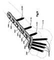
本発明の骨プレートはいかなる特定の形態、大きさ、または構造にも限定されるものではない。例えば、一実施形態での骨プレートは、頭部および軸部を有している。頭部は骨の骨幹端に適合するように構築化し且つ寸法化されており、軸部は骨の骨幹に適合するように構築化され且つ寸法化されている。別の例示的な実施形態での頭部は、曲面を有し且つ軸部の前側と実質的に平行な前方フォーク、および軸部の後側から伸長する後方フォークを含有している。さらに別の例示的な実施形態での頭部は、軸部から外側に向かって広がり、且つカーブしたり、先が細くなったり、ねじれたりする。 The bone plate of the present invention is not limited to any particular form, size, or structure. For example, the bone plate in one embodiment has a head and a shank. The head is constructed and dimensioned to fit the bone metaphysis, and the shaft is constructed and dimensioned to fit the bone shaft. The head in another exemplary embodiment includes a front fork having a curved surface and substantially parallel to the front side of the shaft, and a rear fork extending from the rear side of the shaft. In yet another exemplary embodiment, the head extends outward from the shank and curves, tapers, and twists.
本発明の骨プレート穴はいかなる特定の数や配列にも限定されるものではない。随意に、本発明の骨プレート穴は非ロックネジを配置する多様性を上げるため、拡張されたネジ切りされない部分を有してもよい。本発明の骨プレートはまた、従来のどちらの型の穴も必要ではないし推奨もしないが、接合用の穴、並びに従来のネジ切りされたネジ穴および/またはネジ切りされないネジ穴を随意に有してもよい。 The bone plate holes of the present invention are not limited to any particular number or arrangement. Optionally, the bone plate hole of the present invention may have an extended non-threaded portion to increase the variety of placement of non-locking screws. The bone plate of the present invention also does not require or recommend either conventional type of hole, but optionally has a hole for joining and a conventional threaded and / or unthreaded screw hole. May be.
本発明はまた、骨折部の固定化の方法を提供する。方法は、骨プレートを骨に対して位置付けるステップと、骨ネジを介して挿入するための骨プレート穴を選択するステップと、非ロック骨ネジ、ロック骨ネジ、または角度可変のロック骨ネジのいずれか一つを選択するステップと、選択された骨プレート穴を介して選択された骨ネジを挿入するステップと、適用できれば、穴の中心軸に対する挿入角度を選択するステップと、骨に対して骨プレートを圧迫させるかまたはネジと骨プレートとの間の結びつきを固定させるか、のどちらかをさせるために、ネジ頭部が骨プレート穴に据付けられるまたは締付けられるまで骨にネジをねじ込むステップとを含む。骨ネジは実質的に骨プレートが埋め込まれている限り、骨に残ったままである。 The present invention also provides a method of immobilizing a fracture. The method includes positioning a bone plate relative to bone, selecting a bone plate hole for insertion through a bone screw, and either a non-locking bone screw, a locking bone screw, or a variable angle locking bone screw. Selecting one, inserting a selected bone screw through the selected bone plate hole, selecting an insertion angle with respect to the central axis of the hole, if applicable, and bone to the bone Screwing the screw into the bone until the screw head is installed or tightened into the bone plate hole to either compress the plate or to fix the connection between the screw and the bone plate Including. The bone screw remains in the bone as long as the bone plate is substantially implanted.
本発明の上述および他の利点は、添付の図面(同じ参照番号は通じて同じ部分に関する)の組み合わせに取り込まれた、以下の詳細な説明の考察により明らかになるであろう。
本発明による骨プレートシステムは骨プレート、角度可変のロックネジ、非ロックネジ、および随意にロックネジを含有する。骨プレートは有益的に、骨プレート穴の内面の周囲にネジ山部分を持つ分離した列を有する骨プレート穴を含有する。骨プレートはまた、ネジ山部分を持つ列を備える部分、およびネジ山部分またはネジ山を持たない部分を有する、組み合わせ骨プレート穴を有してもよい。骨プレート穴の型はどちらも有益的に非ロックネジ、ロックネジ、および角度可変のロックネジを受容するように構築されている。随意に、本発明の骨プレートは接合用の穴、および必要ではないが、従来のネジ切りされた穴、滑らかな穴(すなわちネジ山部分またはネジ山を持たない穴)、および/またはそれらの組み合わせを付加的に有してもよい。 The bone plate system according to the present invention includes a bone plate, a variable angle locking screw, a non-locking screw, and optionally a locking screw. The bone plate beneficially contains bone plate holes having separate rows with threaded portions around the inner surface of the bone plate hole. The bone plate may also have a combined bone plate hole having a portion with a row with a threaded portion and a portion with or without a threaded portion. Both types of bone plate holes are beneficially constructed to accept non-locking screws, locking screws, and variable angle locking screws. Optionally, the bone plate of the present invention may be provided with a hole for joining and, although not necessary, a conventional threaded hole, a smooth hole (ie a threaded portion or a hole without a thread), and / or their Additional combinations may be included.
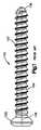
図1は皮質ネジとしても周知である典型的な非ロック骨ネジ100を示している。通常、概して滑面を備え、且つ選択したプレート穴に適合する大きさおよび形状である、ネジ切りされない頭部102を有する外科用の骨ネジは、どれも本発明で使用することができる。例えば、頭部102の形態は円錐状に先細でも、まっすぐな側面でも、球状でも、半球状でもよい。非ロックネジ100は骨への取付けのため、少なくとも部分的にネジ切りされた軸部104を有している。軸部104の長さおよび軸部のネジ山107のネジ山構造(例えばピッチ、輪郭)は、応用により変化を持たせることができる。当技術分野で周知のように、先端106および軸部のネジ山107は骨に埋め込み易くするため、セルフタッピングおよび/またはセルフドリルであってもよい。頭部102および軸部104はまた、適切な配置への補助を施すガイドワイヤを受け取るためのカニューレ108を有してもよい。 FIG. 1 shows a typical
図2は典型的なロックネジ200を示している。通常、本発明で使用することができる外科用の骨ネジは、ネジ切りされた頭部202を有しており、選択したプレート穴に適合する大きさおよび形状である頭部202、およびプレート穴のネジ山部分を持つ列と嵌合するネジ山203を備えている。頭部202の形態は典型的に円錐状の先細であるが、同様に、例えばまっすぐな側面であってもよい。ロックネジ200は骨への取付けのため、少なくとも部分的にネジ切りされた軸部204を有している。軸部204の長さおよび軸部のネジ山207のネジ山構造(例えばピッチ、輪郭)は、応用により変化を持たせることができる。当技術分野で周知のように、先端206および軸部のネジ山207は骨に埋め込み易くするため、セルフタッピングおよび/またはセルフドリルであってもよい。頭部202および軸部204はまた、適切な配置への補助を施すガイドワイヤを受け取るためのカニューレであってもよい。 FIG. 2 shows a
図3Aおよび図3Bは典型的なロックネジ300の頭部302を示している。頭部302上のネジ山303の輪郭は、フランク311により互いに連結されたネジ山の峰310および谷312を含有しており、図3Cに示されるように、隣接する二つのフランク311がネジ山の角度317を形成している。周知のロックネジでよくある円錐状の形態である頭部302は典型的に、線313または線315のようにネジ山の峰310が直線上にあるように、且つ線314または線316のようにネジ山の谷312が別の直線上にあるように位置が定められており、ここで二対の線(313、314)および(315、316)は互いに平行している。さらに、ネジ山の輪郭線であるネジ山の各峰310およびネジ山の谷312は互いに平行して伸長しており、且つ図3Bに示される谷の輪郭線318a〜eで表されるように、ネジの中心軸319と垂直または直交している。頭部302の外面とカッティングビットが接触してネジ山303を切り出すように、輪郭線318a〜eはネジ切りのカッティングビット305の縦軸301を伸長させて形成されている。典型的なロックネジはまた、中心軸に沿って測定されると(例えば319)、一定のネジ山のピッチ(峰から峰、谷から谷、または輪郭線から輪郭線までの距離)を有している。 3A and 3B show the
本発明による角度可変のロックネジは少なくとも部分的に球状のネジ頭部を有している。頭部の球状形状部分はその外面に、好ましくは二重リードのネジ山を有している。ネジ山は、頭部の球状形状部分の弧形状(すなわち直線ではない)の曲率半径をたどる輪郭を有している。ネジ山のピッチは曲率半径に沿って計測されると一定であるが、ネジの中心軸に沿って、頭部の球状形状部分の一方の端(例えば頂上部)から他方の端(例えば最下部)まで測定すると、狭い部分から広い部分、広い部分から狭い部分へと変化することに留意されたい(図32〜図35およびさらに以下の説明を参照のこと)。このネジ山の輪郭により角度可変のロックネジは、選択した角度に関わらず骨プレートとの接触度を同じままに有益的に維持しながら、選択可能な角度範囲内の角度で本発明の骨プレート穴と係合させることができる。すなわち、可能な角度範囲内での骨プレート穴の中心軸に対するネジの角度は、プレート穴の内面に対するネジ頭部のネジ山との係合に影響しない。ネジ頭部の球状形状部分にあるネジ山は、正確に同じ様式で、ぴったりとした適合を確保しながらネジ山部分を持つ列と係合するため、ネジが骨プレート穴に挿入される角度に関わらず(角度範囲内で)、堅固な締結が有益的にネジと骨プレートとの間に得られる。 The variable angle locking screw according to the invention has at least a partially spherical screw head. The spherically shaped part of the head has preferably double lead threads on its outer surface. The thread has a contour that follows the radius of curvature of the arcuate shape (ie not straight) of the spherical portion of the head. The thread pitch is constant when measured along the radius of curvature, but along the central axis of the screw, from one end (eg, the top) of the spherical portion of the head to the other end (eg, the bottom) Note that the measurement changes from narrow to wide and from wide to narrow (see FIGS. 32-35 and further below). This thread profile allows the variable angle lock screw to maintain the same degree of contact with the bone plate regardless of the selected angle while maintaining the bone plate hole of the present invention at an angle within a selectable angle range. Can be engaged. That is, the angle of the screw relative to the central axis of the bone plate hole within the possible angular range does not affect the engagement of the screw head thread with the inner surface of the plate hole. The thread on the spherically shaped part of the screw head engages the row with the threaded part in the exact same manner, ensuring a snug fit, so that the angle at which the screw is inserted into the bone plate hole Regardless (within the angular range), a tight fastening is beneficially obtained between the screw and the bone plate.
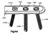
本発明の骨プレートシステムの有益的な特徴のいくつかは、ラック・ギアおよびピニオン・ギアを用いて説明され得る。骨プレートシステム並びにラック・ギアおよびピニオン・ギアは非常に無関係ではあるが(例えばラック・ギアおよびピニオン・ギアは自動車の操縦機構、並びに機関車および鉄道車両の運転機構に使用される)、本発明の骨プレートシステムは類似する構想を共有している。図4A〜Cに示されるように、ラック・ギアおよびピニオン・ギア400は、歯421を有するラック420、および歯423を有する円形のピニオン422を有している。ピニオン422に適用させた回転運動によりラック420を平行移動させるのだが、逆に言えば、ラック420の直線運動または平行移動がピニオン422を回転させる。 Some of the beneficial features of the bone plate system of the present invention can be described using rack gears and pinion gears. Although the bone plate system and rack and pinion gears are very irrelevant (eg, rack gears and pinion gears are used in motor vehicle steering mechanisms and locomotive and railway vehicle driving mechanisms), the present invention The bone plate system shares a similar concept. As shown in FIGS. 4A-C, the rack and
類似した構想とは、ピニオン422の曲率半径425の周囲にある歯423の配列である。図4Bおよび図4Cの輪郭で示されるギアの歯423は等しい角度間隔をあけており、且つ曲率半径425をたどっている。さらに、各歯423は線427で表されるように、歯423を二等分する線が曲率半径425の中心426と交差するように位置を定められており、ここで曲率半径425は半径424を有する円を形成している。同様に、線429で表されるように隣接する歯423の間にあるわずかな間隔428を二等分する線もまた中心426と交差している。本発明による角度可変のロックネジの頭部にあるネジ山の輪郭(ネジの中心軸と垂直する方向に観察される)は、図4Cにあるピニオンの歯423および間隔428の断面の輪郭と類似している。 A similar concept is an array of
図5A〜Cは、本発明による角度可変のロックネジの実施形態を示している。角度可変のロックネジ500は部分的に球状の頭部502および軸部504を有している。頭部502はネジ山503を有し、軸部504はネジ山507を有している。好ましくは頭部502は、ネジを骨にねじ込んだり抜き出したり、且つネジを骨プレート穴にねじ込んだり抜き出したりするための器具を受容するための凹部509を有している。好ましくは、先端506および軸部のネジ山507は骨に埋め込み易くするため、セルフタッピングおよび/またはセルフドリルである。頭部502および軸部504は適切な配置への補助を施すガイドワイヤを受け取るためのカニューレ状であってもよい。図5Bおよび図5Cは曲率半径525を有益的にたどるネジ山503の輪郭を示している。一実施形態での半径は約2mmである。輪郭で理解されるようにネジ山503の各峰510および各谷512は、好ましくは等しい増分角度で分離されている。峰510および谷512は、この実施形態では好ましくは約60度であるネジ山の角度517で、フランク511により連結されている。ネジ山の輪郭線518a〜fは、谷512を介して伸長し、且つ曲率半径525の中心526と交差する一連の線になっている。ネジ山の輪郭線518a〜fは、ネジ切りのカッティングビット505が頭部502の球状の外表面と接触してネジ山503を切り出すように、カッティングビットの縦軸501を伸長させて形成されている。この実施形態では、カッティングビット505はネジ山503が切り出されるように、常に頭部502の球状の外面と垂直である。この実施形態ではまた、半径の中心526がネジ500の中心軸519上にあるような曲率半径となっている。ネジの半径の長さおよび寸法によって、中心526はネジの中心軸上にあっても、またはなくてもよい。さらにネジの寸法が一定のままでも半径が延びるため、例えば図6に示されるように、半径の中心はネジ頭部の外側に移っていく。 5A-C illustrate an embodiment of a variable angle lock screw according to the present invention. The variable
図6は本発明の角度可変ロックネジの別の実施形態を示している。この実施形態での角度可変ロックネジ600のネジ頭部602は、ネジ500よりも大きい曲率半径625を有している。これがネジ600の中心軸619からの距離630(垂直に測定される)である曲率半径の中心626と交差する谷の輪郭線618a〜fになる。例えば2.4mmのネジ(2.4mmは軸604の外径を参照とする)に対して半径624が10mmであれば、距離630は約8.2mmとなる。しかし、曲率半径が大きくなるにつれ、ネジ頭部は球状の形態が失われていき、ネジ頭部の輪郭が周知のロックネジ頭部のように直線(線313〜316のような)になることに留意されたい。 FIG. 6 shows another embodiment of the variable angle lock screw of the present invention. The
図7は本発明に従う角度可変のロックネジ頭部のさらに別の実施形態である。ネジ頭部702は中心軸719、ネジ山703およびねじ込み器具/抜き出し器具を受容する凹部709を有している。前の実施形態のように、ネジ山703の輪郭は有益的に弧形状(すなわち直線ではない)の曲率半径725をたどっており、且つネジ山の峰710、谷712、およびフランク711を含有している。しかし、前の実施形態と異なり、ネジ山の輪郭線は曲率半径の中心と交差していない。代わりに、谷の輪郭線718a〜fで表されたネジ山の輪郭線は、各々が平行し且つ中心軸719と垂直に伸長している。これらの線は、ネジ切りのカッティングビット705が頭部702の外球面と接触してネジ山703を切り出す方法のためにこうした様式で伸長しており、線718a〜fはカッティングビット705の縦軸701を伸長させた線を表している。この相違により、機能的にネジ頭部/穴のネジ山の係合が理想的ではなくなる。しかし、ネジの頭部702は現在のところネジ頭部502よりも製造し易い。 FIG. 7 shows still another embodiment of the variable angle lock screw head according to the present invention. The
図8は、ロック骨プレート穴832を含有する従来の骨プレート穴、非ロック骨プレート穴834、およびロック/非ロック骨プレート穴の組み合わせ穴836を有する骨プレート800である。各型の穴は頂面837から底面の骨との係合面839を貫通して伸長している。ロックプレート穴832は、ロック骨ネジの頭部の周囲にあるネジ山と係合するために、穴の内面の周囲に伸長するネジ山833を有している。従来のロックプレート穴は、示されるように頂面837から底面839まで貫通して伸長するネジ山833を有しても、または骨プレートの頂面と底面との間の垂直方向距離の一部分にのみ伸長するネジ山を代わりに有してもよい。非ロックプレート穴834は非ロック骨ネジの頭部と適合する、ネジ切りされない内面または滑らかな内面835を有している。ロック/非ロックプレート穴の組み合わせ穴836により骨プレートの多用途性が増すため、外科医は穴を介してロックネジまたは非ロックネジのいずれかを使用することができる。組み合わせ穴836は、穴の内面の周囲にロック骨ネジを受容するためのネジ山833を備えた一端と、代わりとして非ロック骨ネジを受容するための滑らかな、またはネジ切りされない内面835を備えた他端とを有している。 FIG. 8 is a
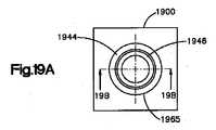
図9Aおよび図9Bは本発明と一致する、骨プレート穴940を有する骨プレート900を示している。従来のロックネジ用の骨プレート穴のように、プレート穴の内面935の周囲にあるらせん形のネジ山の代わりに、本発明の骨プレート穴は、穴の内面の周囲に好ましくはネジ山部分を持つ垂直方向の分離した列942を有している。ネジ山部分を持つ列は、各々が結びつくように拡張されると(すなわち、全面的に内面935の周囲に伸長されると)、らせん形のネジ山を形成する。列は上面937から下面939の方向に伸長し、且つ好ましくは穴の内面の周囲で等距離に離れて間隔を空けている。列ごとのネジ山部分921の数は、外科的応用により、且つ骨プレートおよび骨ネジの寸法(例えばプレートの厚さやネジ山のピッチ)により変化を持たせることができる。しかし、各列は少なくとも二つのネジ山部分を有すべきであり、且つネジとプレートとの間の固定した角度関係を確保するために、好ましくは二つ以上のネジ山部分を有すべきである。 9A and 9B illustrate a
ネジ山部分の代わりとして、列942はその列上に形成した複数の歯を二者択一的に有してもよいことに留意されたい。歯を持つ列は、互いに結びつくように拡張すると(すなわち、内面935の周囲全面に伸長すると)、らせん形のネジ山を形成するのではないが、骨プレート穴の中心軸と垂直な一連の同心の尾根および溝を形成する。このような歯の列もまた、非ロック骨ネジ、ロック骨ネジ、角度可変のロック骨ネジを受容可能であるものの、ロック骨ネジおよび角度可変のロック骨ネジのネジ頭部のネジ山との歯の係合は、ロック骨ネジおよび角度可変のロック骨ネジのネジ頭部のネジ山とのネジ山部分との係合よりも理想的ではない。 Note that as an alternative to the thread portion,
本発明の骨プレート穴は好ましくは、図9Aおよび図9Bで示されるように、ネジ山部分を持つ列942を四列有している。しかし本発明の骨プレート穴は、代わりとして別の列数のネジ山部分を持つ列を有してもよい。 The bone plate holes of the present invention preferably have four
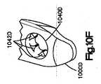
例えば図10A〜Cおよび図10D〜Fの二つの実施形態で説明されるように、それぞれ、骨プレート1000Aおよび1000Dの各骨プレート穴1040Aおよび1040Dは、各々が六列のネジ山部分を持つ列を有している(前に示しているため、図10Cおよび図10Fでは三列のみ明白であることに留意されたい)。ネジ山部分を持つ列1042Aとネジ山部分を持つ列1042Dとの間には相違点があり、ネジ山部分1042Aの列幅1041Aが、ネジ山部分1042Dの列幅1041Dの約二倍になっている。七列以上のネジ山部分を持つ列は、ネジ山部分を持つ列とネジ頭部のネジ山が斜めに係止する危険が増すため推奨しない。反対に、二列以下のネジ山部分を持つ列を有する本発明の骨プレート穴もまた、骨/プレート接合部分における安定性が不十分になる可能性が高まるため推奨しない。 For example, as described in the two embodiments of FIGS. 10A-C and FIGS. 10D-F, each of the bone plate holes 1040A and 1040D of the
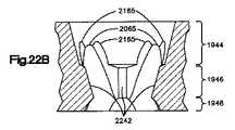
図11は本発明による骨プレート穴の断面図を示している。骨プレート穴1140は骨プレート1100に形成され、且つ骨プレート1100を介し、上面1137から骨と結合する下面1139まで貫通して伸長している。穴1040は上部1144、中央部1146、および底部1148を包含する内面1135を有している。上部1144は上面1137から中央部1146まで伸長している。中央部1146は上部1144から底部1148まで伸長しており、且つ好ましくは穴の最小直径を有している。底部1148は中央部1146から下面1139まで伸長している。上部1144はネジ切りされず、好ましくは滑らかな内面1143を有しており、且つ下面内部方向に好ましくは円錐形の先細になっている。骨プレート穴1140は、上部1144と中央部1146との交点に肩部1145を有している(肩部は各列にある一番目のネジ山部分の頂上である)。肩部1145は穴1140を介して挿入された非ロック骨ネジのネジ頭のための止め部として機能してもよく、一実施形態では、穴の中心軸に対し約60度の角度を形成するように角度付けされている。内面1143または上面1137が頭部の大きさや形態により、非ロック骨ネジのネジ頭部のための止め具として機能してもよいことに留意されたい。底部1148もまた、好ましくは滑らかな内面1149を有し、且つ好ましくはアンダーカットされた球状の形で上面内部方向に先細である。本発明の一実施形態でのアンダーカットされた球状の半径は、約1.75mmである。例えば骨プレートの厚さが2mm厚くなると、上部が約1mm伸長することができ、中央部および底部が各々、約0.5mm伸長することができる。 FIG. 11 shows a cross-sectional view of a bone plate hole according to the present invention. A
この実施形態での骨プレート穴1140の中央部1146は、内面1135にネジ山部分を持つ四列の分離した列1142を有している。各列1142は好ましくは、中心軸1119に対して測定される角度1150で、下面1139の内側方向に傾斜している。一実施形態での角度1150は、好ましくは約15度である。各列1142はまた、好ましくは四つまたは五つのネジ山部分1121を有している。別の実施形態が、上述した数ほどのネジ山部分を有してもよい。2.4mmの角度可変のロックネジを適合させる骨プレート穴のためには、各ネジ山部分を持つ列幅1141が好ましくは約0.35mmである。応用により、別の実施形態が異なる列幅を有してもよい。 The central portion 1146 of the
図12は、ネジ山部分1221を持つ列1242の一部分の断面輪郭を示している(上述のように、代わりとして歯を持つ列の断面の輪郭がネジ山部分と同じように表示されることに留意されたい)。図12では、列1242にある五つのネジ山部分1221のうち二つが示されている。ネジ山部分を持つ列1242は、好ましくは骨プレートの下面方向に角度1250で傾斜している。一実施形態での角度1250は、約15度である。輪郭で見られるように、ネジ山部分1221を持つ列1242は、ネジ山の角度1217でフランク1211により互いに連結された峰(または頂)1210および谷(または谷底)1212を含有している。峰1210は好ましくは、一実施形態で約0.04mmである長さ1252を有している。谷1212は好ましくは、一実施形態で約0.03mmである半径1254を有している。角度1217は好ましくは約60度であり、且つ谷の輪郭線1218で表されるように、谷1212の二等分はフランク1211から測定されると、好ましくは約30度の角度1256で生じている。骨プレート穴のネジ山部分を持つ列の別の実施形態では、代わりとして、列の傾斜角度、峰の長さ、谷の半径、ネジ山の角度、および二等分の角度(ネジ山の角度の作用である)を、異なる値で有してもよい。 FIG. 12 shows a cross-sectional profile of a portion of a
本発明の角度可変のロック骨ネジは有益的に、選択可能な角度範囲内の選択可能な角度で骨にねじ込み、且つ骨プレートに締付けることができる。図13は本発明の実施形態を示しており、骨プレート1300は本発明に従って構築された骨プレート穴1340を有している。各穴1340は、同様に本発明に従って構築された角度可変のロックネジ1360を、選択可能な角度範囲内の角度でいかなる方向でも有益的に受容することができる。角度範囲は角度1362を有する円錐を形成しており、この実施形態では約30度である。換言すれば、角度可変のロックネジ1360は、骨プレート1340の中心軸1319に対し、0度から15度までの選択可能な角度でいかなる方向でも穴1340に挿入し、且つ骨プレート1300に締付けることができる。 The variable angle lock bone screw of the present invention can be beneficially screwed into the bone at a selectable angle within a selectable angular range and tightened to the bone plate. FIG. 13 illustrates an embodiment of the present invention, where the
図14A〜図17Bは本発明に従って構築された骨プレート穴の有益的な特徴を示している。骨プレート1400は少なくとも三つの骨プレート穴1440を有している。各穴1440はネジ山部分を持つ列1542を四列有しており、非ロック骨ネジ、ロック骨ネジ、または角度可変のロック骨ネジのいずれか一つを有益的に受容することができる。 14A-17B illustrate beneficial features of bone plate holes constructed in accordance with the present invention.
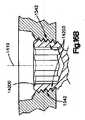
図14A、図14B、図15A、および図15Bに示されるように、従来の非ロック骨ネジ14100は骨プレート穴1440の一つを介して挿入できる。非ロック骨ネジ14100は、穴1440で使用するため各々適切な大きさであり且つ形成された、ネジ切りされないネジ頭部14102、およびネジ切りされた胴部14104を有している。非ロック骨ネジ14100は、必ずしも穴1440を介して穴の中心軸に対して同軸に挿入する必要はなく、代わりに、図14Bで示されるように、穴1440を介して選択可能な角度で挿入してもよいことに留意されたい。図15Bは、ネジ頭部14102がネジ山部分を持つ列1542と係合しないが、代わりに、穴に全体が据付けられると穴1440の肩部1545と接触することを示している。 A conventional
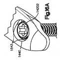
図14A、図14B、図16A、および図16Bは二番目の骨プレート穴1440を介して挿入された従来のロック骨ネジ14200を示している。ロック骨ネジ14200は、ネジ頭部の外面上にネジ山14203を備えるネジ頭部14202を有している。ネジ山14203が、ネジ山部分を持つ列1542と係止しながら係合し且つ嵌合する事ができるように、ネジ頭部およびネジ山の両方ともに適切な大きさであり且つ寸法化されている。ネジ山部分を持つ列1542と正確に係合し且つ嵌合するように、ロック骨ネジ14200は穴1440を介して穴の中心軸1419と同軸に挿入されるべきである。ネジ14200もまた、骨と係合するためのネジ切りされた胴部14204を有している。胴部14204も同様に穴1440を介して挿入するために、適切な大きさであり且つ寸法化されている。 14A, 14B, 16A, and 16B show a conventional
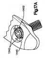
図14A、図14B、図17A、および図17Bは三番目の骨プレート穴1440を介して挿入された角度可変のロック骨ネジ1460を示している。本発明に従って構築された角度可変のロック骨ネジ1460は、ネジ切りされた胴部1404および頭部の外表面上にネジ山1403を備える部分的に球状の頭部1402を有している。ネジ頭部のネジ山1403は頭部1402の球状形状部分である弧形状(すなわち直線ではない)の曲率半径を有益的にたどる輪郭を有している。ネジ1460は、ネジ山部分を持つ列1542と締付けながら係合するネジ山1403を備え、中心軸1719と非同軸に三番目の穴1440へと挿入されていることが示されている。 FIGS. 14A, 14B, 17A, and 17B show a variable angle locking
図18A〜図24Cは、本発明による骨プレート穴の実施形態の種々の特徴を説明している。穴の内面の周囲にある列の構造以外では、少なくともいくつかあるこれらの特徴を、本発明による骨プレート穴の代わりとなる実施形態で使用する必要はない。また、これらの特徴が記載され且つ示される順序は、本発明の骨プレート穴を組み立てるための特定の過程の順序又は段階を意味するものでもないことに留意されたい。当技術分野における通常の技術を持った当業者には明白であるように、本発明の穴を組み立てることができる方法は二通り以上存在する。 18A-24C illustrate various features of an embodiment of a bone plate hole according to the present invention. Other than the structure of the rows around the inner surface of the hole, at least some of these features need not be used in alternative embodiments of the bone plate hole according to the present invention. It should also be noted that the order in which these features are described and shown does not imply a particular process order or step for assembling the bone plate holes of the present invention. As will be apparent to those skilled in the art having ordinary skill in the art, there are two or more ways in which the holes of the present invention can be assembled.
本発明の骨プレート穴は典型的に、図18A〜Cで示されるように、円形の開穴1865から始まる。開穴1865は中心軸1819を有しており、且つ骨プレート1800を介して上面1837から下面1839まで貫通して伸長している。一実施形態での開穴の直径は、約2.2mmである。 The bone plate holes of the present invention typically begin with a
図19A〜Cは他の特徴を示さない骨プレート穴の内面の輪郭を示している。骨プレート1900の穴1965の輪郭は、内側方向に先細の上部1944、突出しながら内側方向に先細の中央部1946、およびアンダーカットされた球状の底部1948を含有している。一実施形態での穴の中央部および底部は、各々が中心軸1919に沿って約1mmずつ伸長し、且つアンダーカットされた球状の半径は約1.75mmである。 19A-C show the contour of the inner surface of the bone plate hole without showing other features. The contour of the
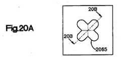
別の特徴は、図20A〜Cで示される随意的な「Xキー」の切り出し2065である。Xキーの切り出し2065は好ましくは、骨プレート穴の開穴1865と同じ中心軸1819の周囲の骨プレートを貫通して、押圧されるか、切り出されるか、または打ち抜かれる。一実施形態での「X」の各脚は約1.5mmの幅を有し、且つ約0.75mmの半径を有する弧形状に至る。この同じ実施形態での共線する脚の端から端までの全長は、約4.25mmである。Xキーの切り出しはクローバーの葉の形を形成して、以下の図25A〜図27Dで記述されるように、相補するドリルガイドの先端図を有するドリルガイドと適合することを目的とする。 Another feature is the optional “X key”
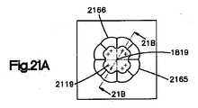
別の特徴は、図21A〜C(他の穴の特徴は何も示していない)で示されるように、好ましくは12度のレリーフカット2165である。レリーフカット2165は八面の対称的なカット断面2166(四分円につき二面の断面)を含有しており、ここで各断面は骨プレートの上面2137から約12度で内部に傾斜している。レリーフカットは骨プレートを貫通して形成されている。一実施形態での各レリーフカットの軸2119は、骨プレート穴の中心軸1819から約1.1mmである。 Another feature is a 12
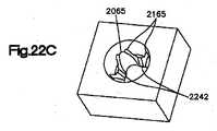
図22A〜Cは上部1944、中央部1946、底部1948、Xキーの切り出し2065、レリーフカット2165、および歯状部分またはネジ山部分の切り出しをまだ有さずに形成された四列の列2242を備えた穴の輪郭を示している。列2242は穴の中央部の内面から軸方向の断面を取り除くことで形成されている。 FIGS. 22A-C show a
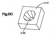
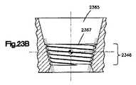
ネジ切り過程により、列2242でネジ山部分が形成される。中央部1946が中央部に形成した列を有していなければ、図23A〜Cで示されるように、ネジ切り過程により、穴2365の中央部2346の内面内に且つ周囲全体にらせん状のネジ山2367が切り出されたであろうことに留意されたい。ネジ山部分のネジ山の輪郭(すなわち峰、谷、フランク、および隣接するフランクにより形成された角度)は、図11および図12で示されたネジ山部分を持つ列について上述した輪郭と、好ましくは同じである。 Due to the threading process, a thread portion is formed in the
前述したように、列2242でネジ山部分を形成する代わりに歯を形成してもよい。歯は穴の中心軸と垂直または少なくとも実質的に垂直する列に溝を切り出すことで形成される。中央部1946が中央部に形成した列を有していなければ、溝を切り出す過程により、同心で平行な一連の交互する溝および尾根を形成したであろうことに留意されたい。 As previously described, teeth may be formed instead of forming threaded portions in
図24A〜Dは本発明による骨プレート穴の完全な実施形態を示している。穴2440はネジ山部分を持つ列2442、Xキーの切り出し2065、およびレリーフカット2165を含有している。図24Cが穴2440の頂面2437を示す一方で、図24Dは骨と接触、隣接、または対面する穴2440の底面2439を示している。 Figures 24A-D show a complete embodiment of a bone plate hole according to the present invention.
図25A〜図27Dはドリルガイドとの接続における本発明の別の有益的な特徴を示している。本発明に従って構築されたドリルガイドの一実施形態が図25A〜図26Cで示され、別の実施形態が図27A〜Dで示されている。 Figures 25A-27D illustrate another beneficial feature of the present invention in connection with a drill guide. One embodiment of a drill guide constructed in accordance with the present invention is shown in FIGS. 25A-26C, and another embodiment is shown in FIGS. 27A-D.
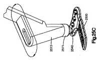
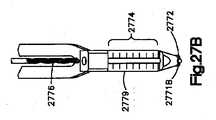
図25Aは先端2571および柄部2573を有するドリルガイド2570を示している。図25Bで示されるように先端2571は、ドリル、骨ネジ、および/または骨プレート2500を介し選択可能な角度で骨にねじ込み/引き抜く器具、を先導するためにドリル軸の周囲に配列された、クローバーの葉の形を形成する、等距離に間隔を空け且つ曲線的な羽または断面2572を四つ有している。羽2572は、骨プレート穴2540のXキーの切り出し1965内にぴったりと適合する大きさであり且つ構築されている。これによりドリルガイド2570は、骨プレート穴2540と同軸に(すなわち骨プレート穴の中心軸と同軸に)挿入され、且つ骨に穴が穿孔される間および/または骨に骨ネジがねじ込まれる間、適所に保つことが容易となる。代わりとして、クローバーの葉の形およびXキーの切り出し以外の構造が、先端2571および穴2540のそれぞれに使用できることに留意されたい。図25Cで示されるように、柄部2573は先端2571および先端2571が挿入される穴2540の中心軸の周囲を360度旋回できる。 FIG. 25A shows a
図26Aは、スロットを介して選択可能な角度範囲内で穿孔を成すことができる、スロット2675を有するドリルガイド2570を示している。この実施形態での選択可能な角度範囲は0度から15度までである。柄部2573は360度旋回させることができるので、それにより穴の中心軸の周囲には30度の角度形成をした円錐が成される。ドリルガイド2570はスロット2675に沿って標識2674a〜dを有しており、この実施形態では穴の中心軸に対し、それぞれ0度、5度、10度、および15度を表示している。別の実施形態では選択可能な角度の別の角度範囲および/または別の標識を有してもよい。図26Aおよび図26Bは、最上部の角度設定2674aで、ドリルガイド2570を経て骨プレート2500を介し骨2678に先導されるドリルビット2676を示しており、この実施形態では骨プレート穴の中心軸に対し0度である(すなわち同軸である)。図26Cは、最下部の角度設定2674dで、ドリルガイド2570を経て骨プレート2500を介し骨2678に先導されるドリルビット2676を示しており、この実施形態では、骨プレート穴の中心軸に対し15度または骨プレート2500の頂面2637に対し75度である。 FIG. 26A shows a
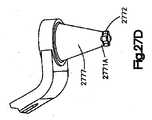
図27A〜Dは本発明に従うドリルガイドの別の実施形態を示している。ドリルガイド2770は、一端に先端2771Aを備えた漏斗形状のガイド2777、逆端に先端2771Bを備えた同軸のガイド2779、およびそれらの間に柄部2773を有している。先端2771Aおよび先端2771Bの各々は、ドリル、骨ネジ、および/または骨プレートを介して骨にねじ込み/引き抜く器具2776、を先導するためにドリル軸の周囲にクローバーの葉の形を形成する、等距離に間隔を空け且つ曲線的な羽または断面2772を四つ有している。羽2772は、本発明の骨プレート穴のXキーの切り出し1965にぴったりと適合する大きさであり且つ構築されている(例えば骨プレート穴2540)。これによりドリルガイド2770のいずれか一端が骨プレート穴と同軸に(すなわち骨プレート穴の中心軸と同軸に)挿入され、且つ骨に穴が穿孔される間および/または骨に骨ネジがねじ込まれる間、適所に保つことが容易となる。代わりとして、クローバーの葉の形およびXキー型の切り出し以外の構造が、本発明の先端2771A、先端2771B、および穴のそれぞれに使用可能であることに留意されたい。ドリルガイド2570の柄部2573と異なり、柄部2773は2771Aおよび2771Bのいずれの先端も旋回しない。代わりに、漏斗形状のガイド2777は先端2771Aが挿入される骨プレート穴の中心軸を介して伸長し、且つ中心軸を中央に合わせた漏斗形状のボア2775を有している。ボア2775は円錐の角度形成を成しており、この実施形態では30度である。本発明の骨プレート穴に挿入された漏斗形状のガイド2777を用い、それにより固定位置に締結させることで、穴の中心軸に対して、0度から15度までの選択可能な角度でいかなる方向でも有益的に穿孔することができる。ドリルガイド2770の逆端にある同軸のガイド2779はガイドを介して伸長するボア2778を有している。本発明の骨プレート穴に挿入された同軸のガイド2779を用いることで、ボア2778は、穴の中心軸と同軸にドリルビットまたはねじ込み/引き抜く器具2776を先導させるように使用することができる。同軸のガイド2779はまた、侵入度の測定に役立つ随意の測定ゲージ2774を有している。 27A-D show another embodiment of a drill guide according to the present invention. The
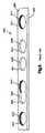
図28は本発明に従う骨プレートの構造を示している。骨プレート2800は、外側近位の脛骨プラトーの骨折部用に形態化され、且つ構築されているが、これに限定されるものではない。骨プレート2800は、外側近位の脛骨の骨幹端と適合するように構築され且つ寸法化された頭部部分2880、および外側近位の脛骨の骨幹と適合するように構築され且つ寸法化された軸部2882を有している。骨プレート2800はさらに、上面2837および骨プレートを上面2837から下面まで貫通して伸長する複数の骨プレート穴2840を有している。各穴2840は四列のネジ山部分を持つ列2842を有しており、本発明による非ロック骨ネジ、ロック骨ネジ、角度可変のロック骨ネジのいずれかを有益的に受容することができる。軸部2882はまた、さらに多用途性を高めるための8の字形状の組み合わせ穴2884をいくつか有しており、8の字形状の片方の部分2885が好ましくは四列のネジ山部分を持つ列を有しており、他方の部分2886が好ましくは滑らかでネジ切りされない。部分2886が非ロック骨ネジを受容できる一方、部分2885は非ロック骨ネジ、ロック骨ネジ、または角度可変のロック骨ネジのいずれかを有益的に受容することができる。骨幹の一部である外側の骨皮質が欠ける、または著しく損傷して、外側の骨皮質の状況により非ロックネジでの固定に問題がある場合、軸部2882で角度可変のロックネジを使用することが特に有用である。骨プレート穴の特定の型および配列はもちろん変化を持たせてよい。 FIG. 28 shows the structure of a bone plate according to the present invention. The
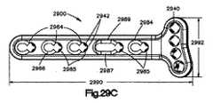
図29A〜Cは本発明に従う別の骨プレートの構造を示している(これは図25から図27で示された骨プレートと同じである)。骨プレート2900は橈骨遠位端の骨折用に形態化され且つ構築されているが、これに限定されるものではない。骨プレート2900は橈骨遠位端の骨幹端と適合するように構築され且つ寸法化された頭部部分2980、および橈骨遠位端の骨幹と適合するように構築され且つ寸法化された軸部2982を有している。骨プレート2900はさらに、表面2937、下面2939および骨プレートを表面2937から下面2939まで貫通して伸長する複数の骨プレート穴2940を有している。各穴2940は好ましくは四列のネジ山部分を持つ列2942を有しており、本発明による非ロック骨ネジ、ロック骨ネジ、角度可変のロック骨ネジのいずれかを有益的に受容することができる。軸部2982もまた、さらに多用途性を高めるための組み合わせ穴2984および2989をいくつか有している。組み合わせ穴の穴の一部分2985は好ましくは四列のネジ山部分を持つ列2942を有しており、それ以外の部分2986および2987は、好ましくは滑らかでネジ切りされない。部分2986および2987が非ロック骨ネジを受容可できる一方で、部分2985は非ロック骨ネジ、ロック骨ネジ、角度可変のロック骨ネジのいずれかを有益的に受容することができる。一実施形態での骨プレート2900の長さ2990は約65mmであり、頭部部分2980の幅2992は約22.2mmであり、頭部部分2980が軸部2982に対し上向きに傾斜する角度2994は約25度である。 29A-C show the structure of another bone plate according to the present invention (this is the same as the bone plate shown in FIGS. 25-27). The
図30で示されるように、本発明の骨プレートは好ましくは、骨プレートの下面または下側と骨との間の接触を制限および/または最小限にするよう形態化してもよい。骨プレートと骨との間の接触を制限および/または最小限にすることは、血液供給への損傷を緩和させ、且つプレートの除去を簡易させることを含め、いくつかの生物学的且つ機械的な利益が得られる。骨プレート3000と骨との間の接触を制限および/または最小限にする一つの方法は、下面3039の骨プレートの穴と穴との間に半径形または扇形の切り出し3099をプレート3000に設けることである。別の方法が米国特許第5151103号明細書(特許文献1)、第5053036号明細書(特許文献2)、第5002544号明細書(特許文献3)、および第4838252号明細書(特許文献4)に開示されている。これらの特許明細書の内容は参照により本明細書に組み込まれる。 As shown in FIG. 30, the bone plate of the present invention may preferably be configured to limit and / or minimize contact between the bone plate's lower surface or underside and the bone. Limiting and / or minimizing contact between the bone plate and the bone includes several biological and mechanical features, including mitigating damage to the blood supply and facilitating removal of the plate. Benefits. One way to limit and / or minimize contact between
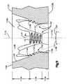
図31は骨折部に適用した場合の本発明の骨プレートシステムの実施形態である。骨プレート2900が、頭部部分2980の骨プレート穴2940を介して選択可能な種々の角度で挿入され、且つ穴2940のネジ山部分を持つ列を通じて骨プレート2900に取付けられた、四つの角度可変のロックネジ3160によって骨折した骨3178に取付けられていることが示されている。骨プレート穴2940の内面にあるネジ山部分を持つ列は、一般的にはラックアンドピニオン式に類似する角度可変のロックネジ3160の球状形状の頭部にあるネジ山と相互作用して嵌合し、これにより角度可変のネジ3160を種々の角度でプレート穴2940に締付けることができる。角度可変のロックネジ3160は、本発明に従って構築されており、例えば角度可変のロックネジ500、600、および/または700であってもよい。骨プレート2900はまた、骨プレート穴2989の一部分2987を介して挿入された非ロック骨ネジ31100によって骨3178に取付けられている。骨プレート2900はさらに、個別の骨プレート穴2984の一部分2985を介して挿入された、一対の従来のロック骨ネジ31200によって骨3178に取付けられ、且つ一部分2985のネジ山部分を持つ列を通じて骨プレートに締付けられている。骨プレート穴にあるネジ山部分を持つ列はロックネジを骨プレートに締付けるようにロックネジのネジ切りされた頭部と嵌合する。ロックネジ31200の代わりに、本発明の角度可変のロックネジが使用できたであろうことに留意されたい。全ての骨プレート穴が各適用において使用する必要はないことに、さらに留意されたい。角度可変のロックネジ3160、非ロックネジ31100、およびロックネジ31200はプレート2900が埋め込まれたままである限り、骨プレート2900を介して骨3178に挿入されたままである。 FIG. 31 shows an embodiment of the bone plate system of the present invention when applied to a fractured part. Four angle
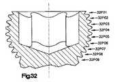
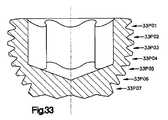
本発明に従って構築された角度可変のロック骨ネジのネジ頭部のネジ山の特徴に戻り、図32〜図34は各ネジの中心軸に沿って測定された、種々のネジ山のピッチ(例えば峰から峰の間隔)を説明する角度可変のロックネジのネジ頭部の三つの実施形態を示している。以下の表は、説明されたネジ頭部が属する角度可変のネジの大きさ、および種々のピッチ(ミリ単位で示す全寸法)を記載している。本発明の角度可変のロック骨ネジの別の実施形態が別の種々のネジ山のピッチを有してもよい。
各事例において、曲率半径に沿って測定されると、隣接するネジ山の峰と峰(または隣接するネジ山の谷と谷)との間の角の間隔は、図35で説明されるように一定であることに留意されたい。すなわち、曲率半径3525に沿って測定されると、隣接するネジ山の峰3510と峰との間の各角度の間隔35ADは、図32〜図34で説明されるようなネジ山のピッチ35P01から35P05と対照的に同じであり、中心軸3519に沿ってまたは平行して測定されると変化する。 In each case, as measured along the radius of curvature, the angular spacing between adjacent thread peaks and peaks (or adjacent thread valleys and valleys) is as illustrated in FIG. Note that it is constant. That is, when measured along a radius of
同じ型の骨プレート穴を使用する同一の骨プレート上で角度可変のロックネジ、ロックネジ、および非ロックネジを組み合わせることにより、本発明は混成された新規の固定化術を提供する。非ロックネジを用いることで、骨プレートと骨との間の摩擦により骨折整復を支える。この摩擦は非ロックネジを骨に堅く締付けることで生じる。しかし、非ロックネジと骨との間の微動が生じると、骨の吸収が生じ、結果的に整復力が失われる。加えて非ロックネジの挿入には、骨がネジの堅い締付けの圧迫に耐える必要があり、非ロックネジを囲む骨には強い圧迫が生じる。通常、圧迫が強いと非ロックネジのネジ山がつぶれて(すなわち骨でネジ山が変形をきたす)、且つ/または骨に変形が生じる恐れがある(骨は粘弾性物質なため)。この現象のどちらか一つでも生じると、結果的に整復力が失われる。By combining variable angle locking screws, locking screws, and non-locking screws on the same bone plate using the same type of bone plate holes, the present invention provides a new hybrid fixation technique. By using a non-locking screw, fracture reduction is supported by friction between the bone plate and the bone. This friction is caused by tightening the non-locking screw tightly on the bone. However, when a fine movement between the non-locking screw and the bone occurs, bone resorption occurs and consequently the reduction force is lost. In addition, insertion of a non-locking screw requires the bone to withstand the tight tightening of the screw, resulting in strong compression on the bone surrounding the non-locking screw. Typically, strong compression will cause the thread of the non-locking screw to collapse (ie, the thread will deform in the bone) and / or deform the bone (since bone is a viscoelastic material). If any one of these phenomena occurs, the reduction force is lost as a result.
少なくとも一つのロックネジまたは角度可変のロックネジを付け足すことで整復力の損失は最小限に抑えられるか、または取り除かれる。具体的には、ロックネジを骨プレートに締付け且つ骨には締付けないことで骨の粘弾性的挙動の影響が減り、ネジ山がつぶれず、且つ微動を防止する。ロックネジと骨プレートとの間の取付けは、固定した角度構成の非常に強い結合をしており、ロックネジは骨を介して横から切られなければ落ちることはない。 By adding at least one lock screw or a variable angle lock screw, the loss of reduction force is minimized or eliminated. Specifically, by tightening the lock screw to the bone plate and not to the bone, the influence of the viscoelastic behavior of the bone is reduced, the screw thread is not crushed, and fine movement is prevented. The attachment between the lock screw and the bone plate is a very strong connection in a fixed angular configuration, and the lock screw will not fall unless it is cut from the side through the bone.
角度可変のネジはロックネジよりも好ましい角度で締付けることができるため、角度可変のネジの使用によりロックネジよりもさらに高い有益性が得られる。 Since a variable angle screw can be tightened at a preferred angle over a lock screw, the use of a variable angle screw provides even greater benefits than a lock screw.
さらに、ある種の関節周囲骨折の処理は、通常骨プレートに対して種々の角度でのネジの挿入が必要であり、且つ個々のネジと骨プレートとの間の初めの角度関係を維持する必要性からも、本発明の高度に多用途性のある骨プレートシステムは、こうした臨床応用に特に適している。 In addition, the treatment of certain periarticular fractures usually requires the insertion of screws at various angles with respect to the bone plate and the initial angular relationship between the individual screws and the bone plate must be maintained. In view of the nature, the highly versatile bone plate system of the present invention is particularly suitable for such clinical applications.
本明細書に記述され説明された特徴は、単独でまたは骨プレートシステムの別の特徴および実施形態との組み合わせで使用してもよいことに留意されたい。 It should be noted that the features described and described herein may be used alone or in combination with other features and embodiments of the bone plate system.
本発明は好ましい実施形態に関連して上述してきた。しかし本発明はこれらの実施形態に限定されるものではなく、本発明の例示でしかない。当業者であれば種々の改良が本発明の範囲内で成されることができ、本発明が以下の特許請求項によってのみ限定されることを理解されるであろう。 The invention has been described above with reference to preferred embodiments. However, the present invention is not limited to these embodiments, and is merely an illustration of the present invention. Those skilled in the art will recognize that various modifications can be made within the scope of the present invention and that the invention is limited only by the following claims.
Claims (25)
Translated fromJapanese前記システムは
中心軸を有する骨ネジであって、
前記骨と係合するように構築され且つ寸法化された軸部;
および曲率半径を有する球状形状の部分を有する頭部;
を包含する骨ネジを具備しており、
前記頭部は前記球状形状の部分の外面にネジ山を有し、
前記ネジ山は峰、谷、およびフランクを包含する輪郭を有し、
且つ前記フランクは前記峰と前記谷とを連結させ、
前記峰と谷とはそれぞれ前記曲率半径と平行または同心する直線ではない曲線上にある、骨プレートシステム。In a bone plate system for fastening a bone plate to bone:
The system is a bone screw having a central axis,
A shaft constructed and dimensioned to engage the bone;
And a head having a spherically shaped portion having a radius of curvature;
A bone screw including
The head has a thread on the outer surface of the spherical portion;
The thread has a contour encompassing peaks, valleys, and flank;
And the flank connects the peak and the valley,
The bone plate system, wherein the peaks and valleys are each on a non-straight curve parallel or concentric with the radius of curvature.
前記骨プレートは、各列が前記上面から前記下面の方向に伸長する、前記穴の円周囲に配列された、歯またはネジ山部分を持つ複数の分離した列を前記穴の内面に有し;
前記穴は非ロック骨ネジ、ロック骨ネジ、または角度可変のロック骨ネジを受容するように構築され且つ寸法化され;
且つ前記歯またはネジ山部分を持つ列は、前記ロック骨ネジの頭部または前記角度可変のロック骨ネジの頭部にあるネジ山と係合するように構築され且つ寸法化されている、骨プレートシステム。A bone plate system for clamping a bone plate to bone, the system comprising a bone plate having a hole with an upper surface, a lower surface engaging the bone, and an inner surface extending through the upper surface to the lower surface. ,
The bone plate has a plurality of separate rows on the inner surface of the hole with teeth or thread portions arranged around the hole circle, each row extending from the upper surface toward the lower surface;
The hole is constructed and dimensioned to receive a non-locking bone screw, a locking bone screw, or a variable angle locking bone screw;
And the row with the tooth or thread portion is constructed and dimensioned to engage a thread on the head of the lock bone screw or the head of the variable angle lock bone screw. Plate system.
各穴が骨プレートを貫通して伸長する、複数の骨プレート穴を有する前記骨プレートを骨に対して位置付けるステップと;
前記骨プレート穴のいずれか一つを介して前記骨に挿入するために、非ロック骨ネジ、ロック骨ネジ、または角度可変のロック骨ネジのいずれか一つを選択するステップと;
前記選択された骨ネジを介して挿入するために前記骨プレート穴のいずれか一つを選択するステップと;
前記選択された骨プレート穴を介して前記選択された骨ネジを前記骨に挿入するステップ
を含む方法。In fracture fixation methods:
Positioning the bone plate with a plurality of bone plate holes relative to the bone, each hole extending through the bone plate;
Selecting any one of a non-locking bone screw, a locking bone screw, or a variable angle locking bone screw for insertion into the bone through any one of the bone plate holes;
Selecting any one of the bone plate holes for insertion through the selected bone screw;
Inserting the selected bone screw into the bone through the selected bone plate hole.
さらに前記方法は、前記ロック骨ネジまたは前記角度可変のロック骨ネジの前記ネジ頭部のネジ山を、前記選択された骨プレート穴の内面に設置された前記歯またはネジ山部分を持つ列に係合させるステップを含む、請求項20に記載の方法。Selecting one of the non-locking bone screw, locking bone screw, or variable angle locking bone screw includes selecting a locking bone screw or variable angle locking bone screw;
Further, the method includes: threading the screw head of the lock bone screw or the variable angle lock bone screw into a row having the teeth or thread portions installed on the inner surface of the selected bone plate hole. 21. The method of claim 20, comprising the step of engaging.
前記選択された骨ネジを挿入するステップが、前記選択された穴の中心軸から角度範囲内の任意の角度でいかなる方向でも、前記選択された骨プレート穴を介して前記選択された角度可変の骨ネジを前記骨に挿入するステップを含む、請求項20に記載の方法。Selecting one of the non-locking bone screw, locking bone screw, or variable angle locking bone screw includes selecting a variable angle locking bone screw;
The step of inserting the selected bone screw can be performed through the selected bone plate hole in any direction at any angle within an angular range from the central axis of the selected hole. 21. The method of claim 20, comprising inserting a bone screw into the bone.
前記選択された穴を介して骨ネジを前記骨に挿入するため、前記ドリルガイドにより可能となる角度範囲内で所望の角度を選択するステップをさらに含み、
前記選択された穴に挿入された前記ドリルガイドの一部分は選択された角度に関わらず前記選択された穴で固定した位置のままである、請求項20に記載の方法。Inserting a portion of a drill guide having curved corners into a corresponding sector cut of the selected hole;
Selecting a desired angle within an angular range allowed by the drill guide to insert a bone screw into the bone through the selected hole;
21. The method of claim 20, wherein a portion of the drill guide inserted into the selected hole remains in a fixed position with the selected hole regardless of the selected angle.
骨プレートの上面から下面まで前記骨プレートを貫通して開穴を穿孔するステップであって、前記開穴が中心軸を有し、且つ前記骨プレートが前記穴の円周囲に内面を有する前記ステップと;
前記穴の周囲の前記内面に上部、中央部、および底部を形成するステップであって、
前記上部が前記上面から前記中央部まで伸長し、
前記中央部が前記上部から前記底部まで伸長し、
且つ前記底部が前記中央部から前記下面まで伸長し、前記中央部が前記上部および前記底部よりも穴の直径が小さい前記ステップと;
前記中央部の内面に複数の列を形成するため、前記穴の中央部の内面から複数の軸方向の断面を取り除くステップと;
前記各列に複数の溝を形成するステップ
を含む方法。In a method of drilling a hole in a bone plate of a bone plate system to fix a fracture in the body, the method includes:
Drilling an aperture through the bone plate from an upper surface to a lower surface of the bone plate, wherein the aperture has a central axis and the bone plate has an inner surface around a circle of the hole When;
Forming a top, center, and bottom on the inner surface around the hole, comprising:
The upper part extends from the upper surface to the central part,
The central portion extends from the top to the bottom;
And the bottom portion extends from the central portion to the lower surface, and the central portion has a smaller hole diameter than the upper portion and the bottom portion;
Removing a plurality of axial cross sections from the inner surface of the central portion of the hole to form a plurality of rows on the inner surface of the central portion;
Forming a plurality of grooves in each row.
Applications Claiming Priority (5)
| Application Number | Priority Date | Filing Date | Title |
|---|---|---|---|
| US95550607P | 2007-08-13 | 2007-08-13 | |
| US60/955,506 | 2007-08-13 | ||
| US11/971,358US8574268B2 (en) | 2004-01-26 | 2008-01-09 | Highly-versatile variable-angle bone plate system |
| US11/971,358 | 2008-01-09 | ||
| PCT/US2008/072894WO2009023666A2 (en) | 2007-08-13 | 2008-08-12 | Highly-versatile variable-angle bone plate system |
Related Child Applications (1)
| Application Number | Title | Priority Date | Filing Date |
|---|---|---|---|
| JP2014176532ADivisionJP6055445B2 (en) | 2007-08-13 | 2014-08-29 | Highly versatile variable angle bone plate system |
Publications (3)
| Publication Number | Publication Date |
|---|---|
| JP2010536427Atrue JP2010536427A (en) | 2010-12-02 |
| JP2010536427A5 JP2010536427A5 (en) | 2011-09-29 |
| JP5608080B2 JP5608080B2 (en) | 2014-10-15 |
Family
ID=39870474
Family Applications (2)
| Application Number | Title | Priority Date | Filing Date |
|---|---|---|---|
| JP2010521118AActiveJP5608080B2 (en) | 2007-08-13 | 2008-08-12 | Highly versatile variable angle bone plate system |
| JP2014176532AActiveJP6055445B2 (en) | 2007-08-13 | 2014-08-29 | Highly versatile variable angle bone plate system |
Family Applications After (1)
| Application Number | Title | Priority Date | Filing Date |
|---|---|---|---|
| JP2014176532AActiveJP6055445B2 (en) | 2007-08-13 | 2014-08-29 | Highly versatile variable angle bone plate system |
Country Status (14)
| Country | Link |
|---|---|
| US (3) | US8574268B2 (en) |
| EP (4) | EP2559392B1 (en) |
| JP (2) | JP5608080B2 (en) |
| KR (1) | KR101569173B1 (en) |
| CN (2) | CN101778604B (en) |
| BR (1) | BRPI0815225A2 (en) |
| CA (2) | CA2696138C (en) |
| CO (1) | CO6260041A2 (en) |
| ES (3) | ES2545778T3 (en) |
| HR (2) | HRP20150800T1 (en) |
| HU (2) | HUE027127T2 (en) |
| PL (3) | PL2559392T3 (en) |
| SI (2) | SI2559394T1 (en) |
| WO (1) | WO2009023666A2 (en) |
Cited By (24)
| Publication number | Priority date | Publication date | Assignee | Title |
|---|---|---|---|---|
| JP2012165976A (en)* | 2011-02-16 | 2012-09-06 | Olympus Terumo Biomaterials Corp | Bone plate and bone plate system |
| KR20140022859A (en)* | 2011-04-01 | 2014-02-25 | 신세스 게엠바하 | Posterior vertebral plating system |
| JP2014036746A (en)* | 2012-08-16 | 2014-02-27 | Mizuho Co Ltd | Plate for fracture treatment |
| JP2015500682A (en)* | 2011-11-18 | 2015-01-08 | シンセス・ゲーエムベーハーSynthes GmbH | Femoral neck fracture implant |
| JP2015525616A (en)* | 2012-06-27 | 2015-09-07 | シンセス・ゲーエムベーハーSynthes GmbH | Variable angle bone fixation device |
| JP2016512711A (en)* | 2013-03-14 | 2016-05-09 | アメイ テクノロジーズ インコーポレイテッド | Variable angle screws, plates and systems |
| JP2016154877A (en)* | 2010-06-02 | 2016-09-01 | シンセス ゲゼルシャフト ミット ベシュレンクテル ハフツングSynthes Gmbh | Bone plate |
| JP2016529998A (en)* | 2013-08-13 | 2016-09-29 | ジンマー,インコーポレイティド | Multi-axis locking mechanism |
| JP2017507739A (en)* | 2014-03-11 | 2017-03-23 | デピュイ・シンセス・プロダクツ・インコーポレイテッド | Bone plate |
| JP2019526375A (en)* | 2016-09-08 | 2019-09-19 | デピュイ・シンセス・プロダクツ・インコーポレイテッド | Variable angle bone plate |
| JP2019526373A (en)* | 2016-09-08 | 2019-09-19 | デピュイ・シンセス・プロダクツ・インコーポレイテッド | Variable angle bone plate |
| JP2020039871A (en)* | 2018-09-06 | 2020-03-19 | グローバス メディカル インコーポレイティッド | Bone fixation anchor, plate and spacer device systems and methods |
| JP2021518223A (en)* | 2018-03-20 | 2021-08-02 | デピュイ・シンセス・プロダクツ・インコーポレイテッド | Bone plate with variable angle locking holes to shape fit |
| JP2021522008A (en)* | 2018-04-30 | 2021-08-30 | デピュイ・シンセス・プロダクツ・インコーポレイテッド | Threaded locking structure for anchoring bone anchors to bone plates |
| US11147599B2 (en) | 2016-08-17 | 2021-10-19 | Globus Medical Inc. | Systems and methods for bone fixation anchor, plate, and spacer devices |
| US11259851B2 (en) | 2003-08-26 | 2022-03-01 | DePuy Synthes Products, Inc. | Bone plate |
| JP2022521011A (en)* | 2019-02-20 | 2022-04-04 | スミス アンド ネフュー インコーポレイテッド | Systems and methods for high tibial osteotomy |
| US11291484B2 (en) | 2004-01-26 | 2022-04-05 | DePuy Synthes Products, Inc. | Highly-versatile variable-angle bone plate system |
| US11389209B2 (en) | 2019-07-19 | 2022-07-19 | Medos International Sarl | Surgical plating systems, devices, and related methods |
| JP2022538525A (en)* | 2019-06-11 | 2022-09-05 | デピュイ・シンセス・プロダクツ・インコーポレイテッド | DEFORMABLE THREADED LOCKING STRUCTURES AND RELATED SYSTEMS AND METHODS |
| US11529176B2 (en) | 2016-09-08 | 2022-12-20 | DePuy Synthes Products, Inc. | Variable angle bone plate |
| US12102361B2 (en) | 2020-10-30 | 2024-10-01 | DePuy Synthes Products, Inc. | Bone plates having multi-use screw holes for locking and compression screws, and related systems and methods |
| US12178481B2 (en) | 2021-01-22 | 2024-12-31 | DePuy Synthes Products, Inc. | Bone plates having multi-use combination holes for locking and dynamic compression, and related systems and methods |
| US12213709B2 (en) | 2019-06-11 | 2025-02-04 | DePuy Synthes Products, Inc. | Deformable threaded locking structures, and related systems and methods |
Families Citing this family (230)
| Publication number | Priority date | Publication date | Assignee | Title |
|---|---|---|---|---|
| US20060200044A1 (en) | 2002-04-19 | 2006-09-07 | Pelikan Technologies, Inc. | Method and apparatus for measuring analytes |
| US7951176B2 (en) | 2003-05-30 | 2011-05-31 | Synthes Usa, Llc | Bone plate |
| DE20321551U1 (en) | 2003-08-26 | 2007-12-27 | Synthes Gmbh | bone plate |
| US8105367B2 (en) | 2003-09-29 | 2012-01-31 | Smith & Nephew, Inc. | Bone plate and bone plate assemblies including polyaxial fasteners |
| US8182485B1 (en) | 2003-11-21 | 2012-05-22 | Toby Orthopaedics, Llc | Fracture fixation system |
| US7637928B2 (en)* | 2004-01-26 | 2009-12-29 | Synthes Usa, Llc | Variable angle locked bone fixation system |
| US8574268B2 (en)* | 2004-01-26 | 2013-11-05 | DePuy Synthes Product, LLC | Highly-versatile variable-angle bone plate system |
| CA2616798C (en) | 2005-07-25 | 2014-01-28 | Smith & Nephew, Inc. | Systems and methods for using polyaxial plates |
| US8382807B2 (en) | 2005-07-25 | 2013-02-26 | Smith & Nephew, Inc. | Systems and methods for using polyaxial plates |
| US20070198016A1 (en)* | 2006-02-21 | 2007-08-23 | Osteomed, L.P. | Compression stabilizing spacers |
| DE202006019220U1 (en)* | 2006-12-19 | 2007-05-24 | Zrinski Ag | Orthopedic screw fastening system for fixing at bone of patient, has through-holes cut on one another so that intersection line and surfaces are produced in direction of plate thickness, where line and surfaces co-operate with head windings |
| US9668759B2 (en)* | 2007-07-11 | 2017-06-06 | Orthohelix Surgical Designs, Inc. | Surgical drill guide having keyway for axial alignment of a fastener for use for an orthopedic plate |
| BRPI0818349A2 (en) | 2007-10-12 | 2015-04-07 | Synthes Gmbh | Reconstruction device |
| AU2008318657A1 (en)* | 2007-10-30 | 2009-05-07 | Synthes Gmbh | Variable angle locked bone plate |
| CA2781407A1 (en) | 2008-01-14 | 2009-07-23 | Michael P. Brenzel | Apparatus and methods for fracture repair |
| US8728126B2 (en)* | 2008-03-10 | 2014-05-20 | Dennis L. Steffen | Bone fixation system and method |
| US20090228010A1 (en) | 2008-03-10 | 2009-09-10 | Eduardo Gonzalez-Hernandez | Bone fixation system |
| CN104068925B (en)* | 2008-03-26 | 2017-07-14 | 斯恩蒂斯有限公司 | For the universal anchor by physical attachment on bone tissue |
| AU2008354730A1 (en) | 2008-04-17 | 2009-10-22 | Toby Orthopaedics, Inc. | Soft tissue attachment system and clip |
| US8257407B2 (en)* | 2008-04-23 | 2012-09-04 | Aryan Henry E | Bone plate system and method |
| US8882838B2 (en)* | 2008-06-05 | 2014-11-11 | DePuy Synthes Products, LLC | Articulating disc implant |
| CN102046111A (en) | 2008-06-05 | 2011-05-04 | 斯恩蒂斯有限公司 | Articulating disc implant |
| US8668694B2 (en)* | 2008-06-06 | 2014-03-11 | Steven M. Teeny | Bone fixation assemblies and methods of use |
| US10251757B2 (en)* | 2008-09-17 | 2019-04-09 | Skeletal Dynamics Llc | Grooved slot allowing adjustment of the position of a bone fixation device for osteosynthesis |
| US20100094352A1 (en)* | 2008-10-10 | 2010-04-15 | Andrew Iott | Bone screw |
| US8784458B1 (en) | 2008-10-10 | 2014-07-22 | Greatbatch Medical S.A. | Polyaxial insert for surgical screws |
| KR20100057240A (en)* | 2008-11-21 | 2010-05-31 | 주식회사 솔고 바이오메디칼 | Apparatus for bone fixation |
| JP5759900B2 (en) | 2008-12-05 | 2015-08-05 | ジンテス ゲゼルシャフト ミット ベシュレンクテル ハフツング | Anchor-in-anchor system for use in bone fixation |
| US9060808B2 (en) | 2008-12-05 | 2015-06-23 | DePuy Synthes Products, Inc. | Anchor-in-anchor system for use in bone fixation |
| WO2011075757A1 (en)* | 2008-12-23 | 2011-06-30 | Austofix Group Pty Ltd | Fixation elements for fixation plates |
| CA2749684C (en) | 2009-01-16 | 2016-04-26 | Carbofix Orthopedics Ltd. | Composite material bone implant |
| DE102009016394B4 (en)* | 2009-04-07 | 2016-02-11 | Merete Medical Gmbh | Device for stable-angle fixation and compression of a fracture site or osteotomy on a bone |
| EP2248479B1 (en) | 2009-05-06 | 2012-09-19 | Greatbatch Ltd. | Bone plate assembly |
| US8986353B2 (en) | 2009-07-09 | 2015-03-24 | Orthohelix Surgical Designs, Inc. | Osteotomy plate, plate driver and method for their use |
| US9259255B2 (en) | 2009-07-15 | 2016-02-16 | Orthohelix Surgical Designs, Inc. | Variable axis locking mechanism for use in orthopedic implants |
| US8834536B2 (en)* | 2009-07-16 | 2014-09-16 | Nexxt Spine, LLC | Cervical plate fixation system |
| GB0914673D0 (en)* | 2009-08-24 | 2009-09-30 | Kumar Deepak | Fracture buttress fixation system |
| US8715326B2 (en)* | 2009-08-28 | 2014-05-06 | Competitive Global Medical, Llc | Distal interphalangeal fusion device and method of use |
| US8758346B2 (en)* | 2009-09-14 | 2014-06-24 | DePuy Synthes Products, LLC | Variable angle compression plate |
| WO2011035103A2 (en)* | 2009-09-18 | 2011-03-24 | Depuy Products, Inc. | Disposable orthopaedic surgery kit and components |
| US10390867B2 (en) | 2009-09-18 | 2019-08-27 | Biomet C.V. | Bone plate system and method |
| DE102009049168A1 (en)* | 2009-10-12 | 2011-04-28 | Normed Medizin-Technik Gmbh | Bone screw and system |
| JP5756118B2 (en) | 2009-11-17 | 2015-07-29 | シンセス ゲゼルシャフト ミット ベシュレンクテル ハフツングSynthes Gmbh | Fixed support pin with variable angle |
| CN102740786A (en)* | 2009-12-22 | 2012-10-17 | 托比骨科有限公司 | Bone plate and tool assembly and method for use thereof |
| US20110178520A1 (en) | 2010-01-15 | 2011-07-21 | Kyle Taylor | Rotary-rigid orthopaedic rod |
| WO2011091052A1 (en) | 2010-01-20 | 2011-07-28 | Kyle Taylor | Apparatus and methods for bone access and cavity preparation |
| US8303667B2 (en) | 2010-03-02 | 2012-11-06 | Alastair Younger | Fastening system for prostheses |
| KR101768706B1 (en)* | 2010-03-04 | 2017-08-16 | 신세스 게엠바하 | Ulna osteotomy system |
| EP2363087B1 (en)* | 2010-03-04 | 2014-05-07 | Alastair Younger | Fastening system for prostheses |
| WO2011112615A1 (en) | 2010-03-08 | 2011-09-15 | Krinke Todd A | Apparatus and methods for securing a bone implant |
| FR2956971B1 (en) | 2010-03-08 | 2012-03-02 | Memometal Technologies | PLATE OSTEOSYNTHESIS SYSTEM |
| FR2956972B1 (en) | 2010-03-08 | 2012-12-28 | Memometal Technologies | ARTICULATED OSTEOSYNTHESIS PLATE |
| KR101821835B1 (en) | 2010-04-27 | 2018-01-24 | 신세스 게엠바하 | Bone fixation systems |
| EP2563250B1 (en) | 2010-04-27 | 2017-11-15 | Synthes GmbH | Bone fixation system including k-wire compression |
| US10154867B2 (en) | 2010-06-07 | 2018-12-18 | Carbofix In Orthopedics Llc | Multi-layer composite material bone screw |
| CN105877829B (en) | 2010-06-07 | 2018-06-22 | 卡波菲克斯整形有限公司 | Composite material bone implant |
| US10368919B2 (en)* | 2010-07-22 | 2019-08-06 | Globus Medical, Inc. | Sacral-iliac stabilization system |
| US8961573B2 (en) | 2010-10-05 | 2015-02-24 | Toby Orthopaedics, Inc. | System and method for facilitating repair and reattachment of comminuted bone portions |
| WO2012058448A2 (en) | 2010-10-27 | 2012-05-03 | Toby Orthopaedics, Llc | System and method for fracture replacement of comminuted bone fractures or portions thereof adjacent bone joints |
| EP2460484A1 (en)* | 2010-12-01 | 2012-06-06 | FACET-LINK Inc. | Variable angle bone screw fixation assembly |
| US8685067B2 (en) | 2010-12-21 | 2014-04-01 | Competitive Global Medical, Llc | Compression plate apparatus |
| US9387020B2 (en)* | 2011-01-10 | 2016-07-12 | Ascension Orthopedics, Inc. | Bone plate system for repair of proximal humeral fracture |
| FR2971144A1 (en) | 2011-02-08 | 2012-08-10 | Tornier Sa | GLENOIDAL IMPLANT FOR SHOULDER PROSTHESIS AND SURGICAL KIT |
| US9283057B2 (en)* | 2011-02-02 | 2016-03-15 | Mid Corp. | System, apparatus and method for implementing implants |
| US8709092B2 (en) | 2011-02-16 | 2014-04-29 | Genesis Medical Devices, LLC | Periprosthetic fracture management enhancements |
| WO2012119146A2 (en) | 2011-03-03 | 2012-09-07 | Toby Orthopaedics, Llc | Anterior lesser tuberosity fixed angle fixation device and method of use associated therewith |
| US20120259367A1 (en)* | 2011-04-08 | 2012-10-11 | Kyphon Sarl | Lumbar-sacral implant allowing variable angle fixation |
| RU2013153116A (en)* | 2011-05-06 | 2015-06-20 | Смит Энд Нефью, Инк. | TARGETING FOR SIGNIFICANT POINTS OF ORTHOPEDIC DEVICES |
| US8771324B2 (en) | 2011-05-27 | 2014-07-08 | Globus Medical, Inc. | Securing fasteners |
| FR2975888B1 (en)* | 2011-05-31 | 2013-06-21 | Cie Financiere Et Medicale | ASSEMBLY COMPRISING AN IMPLANTABLE PART FOR FIXING TO ONE OR MORE BONE OR BONE PARTS TO BE ASSEMBLED, AND AT LEAST ONE FIXING SCREW OF THIS PART IMPLANTABLE TO THIS BONE |
| AU2012271441B2 (en) | 2011-06-15 | 2017-02-02 | Smith & Nephew, Inc. | Variable angle locking implant |
| WO2013021033A1 (en)* | 2011-08-11 | 2013-02-14 | Dietmar Wolter | System comprising a bone plate and a bone screw |
| WO2013036362A1 (en) | 2011-09-06 | 2013-03-14 | Synthes Usa, Llc | Pancarpal arthrodesis bone plate |
| US10751099B2 (en)* | 2011-09-12 | 2020-08-25 | Dietmar Wolter | Bone plate |
| CN102499749A (en)* | 2011-09-30 | 2012-06-20 | 谢友军 | Steel plate for acetabulum |
| US9730797B2 (en) | 2011-10-27 | 2017-08-15 | Toby Orthopaedics, Inc. | Bone joint replacement and repair assembly and method of repairing and replacing a bone joint |
| US9271772B2 (en) | 2011-10-27 | 2016-03-01 | Toby Orthopaedics, Inc. | System and method for fracture replacement of comminuted bone fractures or portions thereof adjacent bone joints |
| US9402667B2 (en) | 2011-11-09 | 2016-08-02 | Eduardo Gonzalez-Hernandez | Apparatus and method for use of the apparatus for fracture fixation of the distal humerus |
| US9198677B2 (en)* | 2011-11-16 | 2015-12-01 | Biomet Manufacturing, Llc | Quick-connect drill guide |
| JP6282596B2 (en)* | 2011-12-07 | 2018-02-21 | スミス アンド ネフュー インコーポレイテッド | Orthopedic implant augment |
| WO2013095756A1 (en)* | 2011-12-20 | 2013-06-27 | Synthes Usa, Llc | Self centering feature for an intramedullary nail |
| US9259217B2 (en)* | 2012-01-03 | 2016-02-16 | Biomet Manufacturing, Llc | Suture Button |
| US20130184765A1 (en)* | 2012-01-16 | 2013-07-18 | Carbofix Orthopedics Ltd. | Multi-axial bone plate fixation |
| US9526549B2 (en) | 2012-01-16 | 2016-12-27 | Carbofix Orthopedics Ltd. | Bone screw with insert |
| EP3061403B1 (en) | 2012-01-24 | 2018-04-18 | Synthes GmbH | Compression screw system |
| US10363140B2 (en) | 2012-03-09 | 2019-07-30 | Si-Bone Inc. | Systems, device, and methods for joint fusion |
| US20130289630A1 (en)* | 2012-04-26 | 2013-10-31 | Daniel Duane Fritzinger | Conical-spherical thread form for variable angle locking systems |
| EP3818947B1 (en) | 2012-05-04 | 2023-08-30 | SI-Bone, Inc. | Fenestrated implant |
| US10405893B2 (en) | 2012-07-12 | 2019-09-10 | DePuy Synthes Products, Inc. | Device, kit and method for correction of spinal deformity |
| CA2882601C (en) | 2012-08-22 | 2020-10-27 | Andreas Appenzeller | Anchor-in-anchor system |
| US20140066998A1 (en)* | 2012-09-06 | 2014-03-06 | Jean-Jacques Martin | Assembly comprising an implantable part designed to be fastened to one or more bones or bone portions to be joined, and at least one screw for fastening the implantable part to said bone(s) |
| US9060821B2 (en) | 2012-11-16 | 2015-06-23 | DePuy Synthes Products, Inc. | Locking and lagging bone screws |
| CN102961179A (en)* | 2012-12-03 | 2013-03-13 | 浙江科惠医疗器械有限公司 | Universal locking and pressurizing bone plate |
| US9283008B2 (en) | 2012-12-17 | 2016-03-15 | Toby Orthopaedics, Inc. | Bone plate for plate osteosynthesis and method for use thereof |
| WO2014111432A1 (en) | 2013-01-15 | 2014-07-24 | Zimmer Gmbh | Surgical bone screw and implant system |
| US9687284B2 (en) | 2013-02-13 | 2017-06-27 | Stryker European Holdings I, Llc | Locking peg with extended thread |
| US9404525B2 (en)* | 2013-03-14 | 2016-08-02 | Imds Llc | Polyaxial locking interface |
| US9103367B2 (en) | 2013-03-14 | 2015-08-11 | Imds Llc | Polyaxial locking interface |
| US9333014B2 (en) | 2013-03-15 | 2016-05-10 | Eduardo Gonzalez-Hernandez | Bone fixation and reduction apparatus and method for fixation and reduction of a distal bone fracture and malunion |
| WO2014145902A1 (en) | 2013-03-15 | 2014-09-18 | Si-Bone Inc. | Implants for spinal fixation or fusion |
| US9545276B2 (en) | 2013-03-15 | 2017-01-17 | Aristotech Industries Gmbh | Fixation device and method of use for a lapidus-type plantar hallux valgus procedure |
| US20150005856A1 (en)* | 2013-06-27 | 2015-01-01 | Boston Scientific Neuromodulation Corporation | Lead anchors and systems and methods using the lead anchors |
| CN105517501B (en) | 2013-07-09 | 2018-09-07 | 德普伊新特斯产品公司 | bone fixation system |
| US20150039038A1 (en)* | 2013-08-05 | 2015-02-05 | Stephan Eckhof | Orthopedic Screw Fastener System Including Locking and Non-Locking Screws |
| US9468479B2 (en) | 2013-09-06 | 2016-10-18 | Cardinal Health 247, Inc. | Bone plate |
| US11147688B2 (en) | 2013-10-15 | 2021-10-19 | Si-Bone Inc. | Implant placement |
| US9848924B2 (en)* | 2013-12-11 | 2017-12-26 | DePuy Synthes Products, Inc. | Bone plate |
| AU2014364307B2 (en)* | 2013-12-11 | 2018-12-20 | DePuy Synthes Products, Inc. | Bone plate |
| CN105939677A (en) | 2013-12-12 | 2016-09-14 | 康文图斯整形外科公司 | Tissue displacement tools and methods |
| US10849708B2 (en)* | 2013-12-12 | 2020-12-01 | The Cleveland Clinic Foundation | Devices and methods for treating medical conditions associated with sacroiliac joint abnormalities |
| US10231766B2 (en) | 2013-12-23 | 2019-03-19 | Smith & Nephew, Inc. | Distal radius plate |
| WO2015103090A1 (en) | 2014-01-03 | 2015-07-09 | Tornier, Inc. | Reverse shoulder systems |
| EP3091912B1 (en)* | 2014-01-08 | 2023-10-25 | Smith&Nephew, Inc. | Drill guide system |
| US9545277B2 (en) | 2014-03-11 | 2017-01-17 | DePuy Synthes Products, Inc. | Bone plate |
| US10226287B2 (en) | 2014-03-31 | 2019-03-12 | Association For The Advancement Of Musculoskeletal | Bone plate with versatile screw holes |
| JP6735529B2 (en) | 2014-07-09 | 2020-08-05 | 国立大学法人東海国立大学機構 | Locking plate system for the treatment of distal radius fractures |
| BR112016023184B1 (en) | 2014-08-22 | 2022-02-22 | Wright Medical Technology, Inc | ENHANCED IMPLANT REVISION COMPONENT |
| AU2015308881B2 (en)* | 2014-08-28 | 2019-03-14 | Zimmer Gmbh | Bone plate system and method |
| KR101665048B1 (en)* | 2014-08-29 | 2016-10-14 | 김일환 | Bone fixation of screw system |
| PL231693B1 (en) | 2014-09-12 | 2019-03-29 | Chm Spolka Z Ograniczona Odpowiedzialnoscia | Bone plate complex with the bone screw for stabilization of fractures |
| US10166033B2 (en) | 2014-09-18 | 2019-01-01 | Si-Bone Inc. | Implants for bone fixation or fusion |
| JP6542362B2 (en) | 2014-09-18 | 2019-07-10 | エスアイ−ボーン・インコーポレイテッドSi−Bone, Inc. | Matrix implant |
| AU2015336928B2 (en)* | 2014-10-24 | 2021-05-27 | Austofix Group Limited | A bone fixation system and a plate therefor |
| CN105596075A (en)* | 2014-11-13 | 2016-05-25 | 无锡市闻泰百得医疗器械有限公司 | Bone plate screw structure |
| CN104398327A (en)* | 2014-12-18 | 2015-03-11 | 上海晟实医疗器械科技有限公司 | Locking screw provided with porous surface and used for bone connection and fixation |
| CN105167835B (en)* | 2014-12-31 | 2019-02-15 | 天津正天医疗器械有限公司 | locking screw |
| AU2016215127B2 (en)* | 2015-02-05 | 2020-12-03 | Paragon 28, Inc. | Bone plates, systems, and methods of use |
| US10064668B2 (en)* | 2015-02-13 | 2018-09-04 | Kls-Martin, L.P. | Bone plate locking cannula and drill guide assembly |
| KR101722747B1 (en)* | 2015-02-25 | 2017-04-03 | 주식회사 제일메디칼코퍼레이션 | Bone plate system |
| DE102016002444A1 (en) | 2015-03-11 | 2016-09-15 | Königsee Implantate GmbH | Osteosynthesis device with a bone plate and with at least one bone screw |
| US9987062B2 (en) | 2015-03-24 | 2018-06-05 | Advanced Orthopaedic Solutions, Inc. | Variable angle bone plate |
| KR101670273B1 (en) | 2015-03-27 | 2016-10-31 | 학교법인 김천대학교 | Locking fixing system for orthopedic implants |
| KR101681078B1 (en)* | 2015-04-17 | 2016-12-01 | 비케이메디텍 (주) | Plate unit |
| US10058362B2 (en) | 2015-05-22 | 2018-08-28 | Gramercy Extremity Orthopedics Llc | Orthopedic bone fixation assembly |
| US9636498B2 (en) | 2015-08-03 | 2017-05-02 | Boston Scientific Neuromodulation Corporation | Lead anchor with a wedge and systems using the lead anchor |
| US20180221067A1 (en)* | 2015-08-06 | 2018-08-09 | Industrias Medicas Sampedro | Divergent, biplanar and segmental plate for bone fixation |
| US11076898B2 (en) | 2015-08-27 | 2021-08-03 | Globus Medical, Inc. | Proximal humeral stabilization system |
| US11197682B2 (en) | 2015-08-27 | 2021-12-14 | Globus Medical, Inc. | Proximal humeral stabilization system |
| US10687874B2 (en) | 2015-08-27 | 2020-06-23 | Globus Medical, Inc | Proximal humeral stabilization system |
| GB2557840B (en) | 2015-09-18 | 2021-07-21 | Smith & Nephew Inc | Bone plate |
| US10130402B2 (en) | 2015-09-25 | 2018-11-20 | Globus Medical, Inc. | Bone fixation devices having a locking feature |
| DE202016100245U1 (en)* | 2015-10-19 | 2017-01-23 | Königsee Implantate GmbH | Surgical guide and surgical drill set |
| CN105213017A (en)* | 2015-10-29 | 2016-01-06 | 创辉医疗器械江苏有限公司 | Lock screw that multi-angle is adjustable |
| US9974581B2 (en) | 2015-11-20 | 2018-05-22 | Globus Medical, Inc. | Expandable intramedullary systems and methods of using the same |
| US10537371B2 (en)* | 2015-12-23 | 2020-01-21 | Osteomed Llc | Wrist plate and drill guide |
| US10617458B2 (en) | 2015-12-23 | 2020-04-14 | Carbofix In Orthopedics Llc | Multi-layer composite material bone screw |
| US11833055B2 (en) | 2016-02-28 | 2023-12-05 | Integrated Shoulder Collaboration, Inc. | Shoulder arthroplasty implant system |
| JP6703144B2 (en) | 2016-02-28 | 2020-06-03 | コンソーシアム オブ フォーカスド オーソペディスツ, エルエルシー | Shoulder arthroplasty implant system |
| WO2017151438A1 (en) | 2016-02-29 | 2017-09-08 | Boston Scientific Neuromodulation Corporation | Lead anchor for an electrical stimulation system |
| US9795411B2 (en) | 2016-03-02 | 2017-10-24 | Globus Medical, Inc. | Fixators for bone stabilization and associated systems and methods |
| US9962192B2 (en) | 2016-03-17 | 2018-05-08 | Medos International Sarl | Multipoint fixation implants |
| US10531905B2 (en) | 2016-04-19 | 2020-01-14 | Globus Medical, Inc. | Implantable compression screws |
| WO2017201058A1 (en) | 2016-05-17 | 2017-11-23 | Boston Scientific Neuromodulation Corporation | Systems and methods for anchoring a lead for neurostimulation of a target anatomy |
| AU2017311669B2 (en) | 2016-08-16 | 2022-08-25 | DePuy Synthes Products, Inc. | Bone fixation system |
| US11197701B2 (en) | 2016-08-17 | 2021-12-14 | Globus Medical, Inc. | Stabilization systems |
| US11213327B2 (en) | 2016-08-17 | 2022-01-04 | Globus Medical, Inc. | Fracture plates, systems, and methods |
| US10751098B2 (en) | 2016-08-17 | 2020-08-25 | Globus Medical Inc. | Stabilization systems |
| US10420596B2 (en) | 2016-08-17 | 2019-09-24 | Globus Medical, Inc. | Volar distal radius stabilization system |
| US11432857B2 (en) | 2016-08-17 | 2022-09-06 | Globus Medical, Inc. | Stabilization systems |
| US11141204B2 (en) | 2016-08-17 | 2021-10-12 | Globus Medical Inc. | Wrist stabilization systems |
| US10383668B2 (en) | 2016-08-17 | 2019-08-20 | Globus Medical, Inc. | Volar distal radius stabilization system |
| US10575884B2 (en) | 2016-08-17 | 2020-03-03 | Globus Medical, Inc. | Fracture plates, systems, and methods |
| US11331128B2 (en) | 2016-08-17 | 2022-05-17 | Globus Medical Inc. | Distal radius stabilization system |
| US10136998B2 (en) | 2016-08-30 | 2018-11-27 | Wright Medical Technology, Inc. | Revision total ankle implants |
| US10299847B2 (en) | 2016-09-22 | 2019-05-28 | Globus Medical, Inc. | Systems and methods for intramedullary nail implantation |
| US10610273B2 (en)* | 2016-11-07 | 2020-04-07 | In2Bones Usa, Llc | Bone plate with transverse screw |
| EP3348218B1 (en)* | 2017-01-13 | 2022-11-16 | Globus Medical, Inc. | Stabilization systems |
| US10709886B2 (en) | 2017-02-28 | 2020-07-14 | Boston Scientific Neuromodulation Corporation | Electrical stimulation leads and systems with elongate anchoring elements and methods of making and using |
| US10881438B2 (en) | 2017-03-10 | 2021-01-05 | Globus Medical, Inc. | Clavicle fixation system |
| US10368928B2 (en) | 2017-03-13 | 2019-08-06 | Globus Medical, Inc. | Bone stabilization systems |
| US10905477B2 (en) | 2017-03-13 | 2021-02-02 | Globus Medical, Inc. | Bone stabilization systems |
| JP2020509863A (en)* | 2017-03-13 | 2020-04-02 | デピュイ・シンセス・プロダクツ・インコーポレイテッド | Proximal femoral plate system |
| US10835739B2 (en) | 2017-03-24 | 2020-11-17 | Boston Scientific Neuromodulation Corporation | Electrical stimulation leads and systems with elongate anchoring elements and methods of making and using |
| US10857351B2 (en) | 2017-04-28 | 2020-12-08 | Boston Scientific Neuromodulation Corporation | Lead anchors for electrical stimulation leads and systems and methods of making and using |
| WO2019010252A2 (en) | 2017-07-04 | 2019-01-10 | Conventus Orthopaedics, Inc. | APPARATUS AND METHODS FOR TREATING BONES |
| CN109262327A (en)* | 2017-07-18 | 2019-01-25 | 中国航空工业集团公司济南特种结构研究所 | A kind of Special-Shaped Surface clamping and groove axle thread processing tool |
| US12318122B2 (en) | 2017-09-13 | 2025-06-03 | Globus Medical, Inc. | Bone stabilization systems |
| US10856920B2 (en) | 2017-09-13 | 2020-12-08 | Globus Medical Inc. | Bone stabilization systems |
| US11096730B2 (en) | 2017-09-13 | 2021-08-24 | Globus Medical Inc. | Bone stabilization systems |
| US11116519B2 (en) | 2017-09-26 | 2021-09-14 | Si-Bone Inc. | Systems and methods for decorticating the sacroiliac joint |
| WO2019079104A2 (en) | 2017-10-16 | 2019-04-25 | Imascap Sas | Shoulder implants and methods of use and assembly |
| KR20190073697A (en) | 2017-12-19 | 2019-06-27 | 학교법인 김천대학교 | Drilling guide mechanism of freely locking fixation system for orthopedic implants |
| KR102009785B1 (en)* | 2017-12-28 | 2019-08-14 | 에이블 주식회사 | Bone joint poly axial plate |
| US11224468B2 (en) | 2018-03-02 | 2022-01-18 | Globus Medical, Inc. | Distal tibial plating system |
| EP4108194A1 (en) | 2018-03-02 | 2022-12-28 | Stryker European Holdings I, LLC | Bone plates and associated screws |
| US11071570B2 (en) | 2018-03-02 | 2021-07-27 | Globus Medical, Inc. | Distal tibial plating system |
| US10898232B2 (en) | 2018-03-20 | 2021-01-26 | Medos International Sàrl | Multipoint fixation implants and related methods |
| ES3011907T3 (en) | 2018-03-28 | 2025-04-08 | Si Bone Inc | Threaded implants for use across bone segments |
| US10772665B2 (en)* | 2018-03-29 | 2020-09-15 | DePuy Synthes Products, Inc. | Locking structures for affixing bone anchors to a bone plate, and related systems and methods |
| US11141172B2 (en) | 2018-04-11 | 2021-10-12 | Globus Medical, Inc. | Method and apparatus for locking a drill guide in a polyaxial hole |
| CN113473918B (en)* | 2018-09-14 | 2024-10-01 | 博恩医疗器械股份有限公司 | Orthopedic bone screw |
| US11000322B2 (en) | 2018-09-20 | 2021-05-11 | DePuy Synthes Products, Inc. | Bone fixation system |
| US10966735B1 (en)* | 2018-10-27 | 2021-04-06 | Eric M. Larsen | Surgical device and method for performing arthrodesis |
| US10925651B2 (en) | 2018-12-21 | 2021-02-23 | DePuy Synthes Products, Inc. | Implant having locking holes with collection cavity for shavings |
| KR102210692B1 (en) | 2018-12-21 | 2021-02-02 | 에이블 주식회사 | Cutting tool for medicall bone joint plate |
| KR20200082384A (en) | 2018-12-28 | 2020-07-08 | 학교법인 김천대학교 | Drilling guide mechanism of freely locked fixation system for orthopedic implants capable of drill depth measurement |
| US10864026B2 (en)* | 2019-02-08 | 2020-12-15 | Steris Instrument Management Services, Inc. | Tibial fixation plate |
| US11202663B2 (en) | 2019-02-13 | 2021-12-21 | Globus Medical, Inc. | Proximal humeral stabilization systems and methods thereof |
| EP4613244A2 (en) | 2019-02-14 | 2025-09-10 | SI-Bone Inc. | Implants for spinal fixation and or fusion |
| FR3092744B1 (en) | 2019-02-14 | 2021-02-26 | Newclip Int | Plate osteosynthesis device with a tapped hole for receiving a locked fixing screw |
| HRP20190451A2 (en) | 2019-03-06 | 2020-09-18 | Janoš Kodvanj | Screw with a variable locking angle and the corresponding system of locking |
| JP7257546B2 (en) | 2019-05-13 | 2023-04-13 | ハウメディカ オステオニクス コーポレイション | Glenoid baseplate and implant assembly |
| US11278334B2 (en) | 2019-05-22 | 2022-03-22 | DePuy Synthes Products, Inc. | Variable angle bone screw having a hardened head |
| US12070253B2 (en)* | 2019-06-07 | 2024-08-27 | Smith & Nephew, Inc. | Orthopedic implant with improved variable angle locking mechanism |
| EP3982848A1 (en) | 2019-08-09 | 2022-04-20 | Howmedica Osteonics Corp. | Apparatuses and methods for implanting glenoid prostheses |
| US11426210B2 (en) | 2019-09-25 | 2022-08-30 | Medos International Sàrl | Multipoint angled fixation implants for multiple screws and related methods |
| US10743922B1 (en) | 2019-09-27 | 2020-08-18 | Trilliant Surgical Llc | Variable angle locking construct for orthopedic applications |
| US12185995B2 (en) | 2019-10-09 | 2025-01-07 | Globus Medical, Inc. | Bone stabilization systems |
| US11129627B2 (en) | 2019-10-30 | 2021-09-28 | Globus Medical, Inc. | Method and apparatus for inserting a bone plate |
| JP7646654B2 (en) | 2019-11-21 | 2025-03-17 | エスアイ-ボーン・インコーポレイテッド | Rod coupling assembly for bone stabilization construct - Patent application |
| AU2020392121B2 (en) | 2019-11-27 | 2025-05-22 | Si-Bone, Inc. | Bone stabilizing implants and methods of placement across SI joints |
| EP4072452A4 (en) | 2019-12-09 | 2023-12-20 | SI-Bone, Inc. | Sacro-iliac joint stabilizing implants and methods of implantation |
| US11723647B2 (en) | 2019-12-17 | 2023-08-15 | Globus Medical, Inc. | Syndesmosis fixation assembly |
| EP4103083B1 (en) | 2020-02-14 | 2024-10-23 | Medos International Sàrl | Integrated multipoint fixation screw |
| US20220117749A1 (en)* | 2020-07-09 | 2022-04-21 | Globus Medical, Inc. | Intradiscal fixation systems |
| USD949341S1 (en) | 2020-09-29 | 2022-04-19 | Trilliant Surgical Llc | Bone fixation plate |
| TWI775172B (en)* | 2020-10-05 | 2022-08-21 | 黃信華 | bone screw |
| EP4225177B1 (en) | 2020-10-05 | 2025-01-15 | DePuy Synthes Products, Inc. | Deformable threaded locking structures and related systems |
| JP7541900B2 (en) | 2020-11-11 | 2024-08-29 | メイラ株式会社 | Variable angle fixing mechanism and bone treatment device using same |
| EP4259015A4 (en) | 2020-12-09 | 2024-09-11 | SI-Bone, Inc. | SACROILIAC JOINT STABILIZATION IMPLANTS AND METHODS OF IMPLANTATION |
| WO2022172172A2 (en) | 2021-02-10 | 2022-08-18 | DePuy Synthes Products, Inc. | Bone plates having compression holes, and related systems and methods |
| US12137951B2 (en)* | 2021-06-11 | 2024-11-12 | DePuy Synthes Products, Inc. | Bone plates having polygonal locking holes with thread interruption, and related systems and methods |
| CN113397677B (en)* | 2021-07-08 | 2025-08-08 | 天津正天医疗器械有限公司 | Fixing device |
| EP4351485A4 (en)* | 2021-08-12 | 2025-04-16 | Howmedica Osteonics Corp. | GLENOID COMPONENT WITH FENESTRATED BEARING |
| WO2023039398A1 (en)* | 2021-09-07 | 2023-03-16 | Integrity Implants Inc. | Ball-nosed pedicle screw |
| USD1041008S1 (en) | 2022-09-06 | 2024-09-03 | Mirus Llc | Bone plate |
| US12064150B2 (en) | 2022-01-19 | 2024-08-20 | Globus Medical Inc. | System and method for treating bone fractures |
| BE1030403B1 (en)* | 2022-03-31 | 2023-10-30 | Life Int | Bone fixation plate |
| TWD227883S (en)* | 2023-03-08 | 2023-10-01 | 博晟生醫股份有限公司 | Medical implantable device set |
| WO2025038769A1 (en) | 2023-08-15 | 2025-02-20 | Si-Bone Inc. | Pelvic stabilization implants, methods of use and manufacture |
Citations (1)
| Publication number | Priority date | Publication date | Assignee | Title |
|---|---|---|---|---|
| DE102005042766A1 (en)* | 2005-07-13 | 2007-01-25 | Königsee Implantate und Instrumente zur Osteosynthese GmbH | Screw connection for bone plate in particular used for osteosynthesis, comprises specifically shaped central bore for flexible use with different screw heads |
Family Cites Families (545)
| Publication number | Priority date | Publication date | Assignee | Title |
|---|---|---|---|---|
| US327296A (en) | 1885-09-29 | William t | ||
| US526910A (en)* | 1894-10-02 | Brierley kelsall rigby | ||
| FR742618A (en) | 1933-03-10 | |||
| US1105105A (en) | 1912-02-10 | 1914-07-28 | William O'n Sherman | Surgical appliance. |
| US1203546A (en) | 1914-09-22 | 1916-10-31 | Stanley Works | Threaded member. |
| US2228584A (en) | 1936-10-26 | 1941-01-14 | Detroit Harvester Co | Fastener clip |
| US2352297A (en) | 1940-07-03 | 1944-06-27 | George F Wales | Bolt |
| US2443363A (en)* | 1942-04-13 | 1948-06-15 | Townsend Kenneth | Bone plate |
| US2477430A (en) | 1943-06-24 | 1949-07-26 | Swanstrom Klas Arent | Locking nut and method of manufacturing the same |
| US2414882A (en) | 1943-09-24 | 1947-01-28 | Herschel Leiter H | Fracture reduction apparatus |
| US2526959A (en) | 1947-07-01 | 1950-10-24 | Frank A Lorenzo | Fracture reduction apparatus |
| US2496126A (en) | 1947-10-28 | 1950-01-31 | Edward J Haboush | Fracture nail and bone plate |
| US2612159A (en) | 1949-03-01 | 1952-09-30 | Marie B Collison | Trochanteric plate for bone surgery |
| US2627855A (en) | 1950-04-07 | 1953-02-10 | James W Price | Fracture nail and bone plate |
| US2846701A (en) | 1950-10-12 | 1958-08-12 | United Carr Fastener Corp | Method of forming a sheet metal lock nut |
| US2772676A (en) | 1951-12-06 | 1956-12-04 | Pohl Ernst | Connecting device for bone fractures in the neighborhood of joints |
| US2699774A (en) | 1952-05-12 | 1955-01-18 | Livingston Herman Harrison | Bone pin locking device |
| US2801631A (en) | 1954-08-18 | 1957-08-06 | Charnley John | Fracture screw adjusting means |
| US2874691A (en) | 1957-02-08 | 1959-02-24 | Christopher A Mason | Femoral nail |
| US3025853A (en) | 1958-07-07 | 1962-03-20 | Christopher A Mason | Fixation device for fractured femur |
| FR83840E (en) | 1962-08-24 | 1964-10-23 | Improvement of fixing elements for roofs such as screws, lag screws or bolts | |
| US3229743A (en) | 1964-05-04 | 1966-01-18 | California Ind Prod Inc | Sheet metal nut with yielding retainer |
| US3314326A (en) | 1964-10-20 | 1967-04-18 | Republic Ind Corp | Self-threading nut with interrupted threads |
| US3374786A (en) | 1964-12-15 | 1968-03-26 | George R. Callender Jr. | Fractured bone setting fastener assembly |
| US3263949A (en) | 1965-05-17 | 1966-08-02 | Teleflex Inc | Screw retaining fitting for a remote control assembly |
| US3364807A (en) | 1965-11-26 | 1968-01-23 | Tinnerman Products Inc | Threadless nut type fastener |
| US3463148A (en)* | 1966-01-20 | 1969-08-26 | Richards Mfg Co | Bone plate |
| USRE28841E (en)* | 1966-06-22 | 1976-06-08 | Synthes A.G. | Osteosynthetic pressure plate construction |
| USRE31628E (en)* | 1966-06-22 | 1984-07-10 | Synthes Ag | Osteosynthetic pressure plate construction |
| CH462375A (en)* | 1966-06-22 | 1968-09-15 | Synthes Ag | Osteosynthetic pressure plate |
| US3388732A (en) | 1967-07-31 | 1968-06-18 | Tinnerman Products Inc | Self-threading fastening device |
| FR1538053A (en) | 1967-08-18 | 1968-09-07 | Osteosynthesis plate combined with its key | |
| US3561437A (en) | 1967-11-08 | 1971-02-09 | Jose Luis Orlich | Apparatus for fixing fractures of the femur |
| US3489143A (en) | 1967-12-15 | 1970-01-13 | William X Halloran | Convertible hip pin |
| FR1599500A (en) | 1968-01-31 | 1970-07-15 | ||
| US3630261A (en) | 1968-02-27 | 1971-12-28 | Rex Chainbelt Inc | Frictional antirotation device |
| US3551389A (en) | 1969-03-04 | 1970-12-29 | Celanese Corp | Process for the polymerization of aromatic polybenzimidazoles |
| US3577601A (en) | 1969-03-12 | 1971-05-04 | Thomas & Betts Corp | Article fastening device |
| CA954430A (en) | 1970-04-03 | 1974-09-10 | Dumont Aviation Associates | Self-locking screw |
| US4040129A (en) | 1970-07-15 | 1977-08-09 | Institut Dr. Ing. Reinhard Straumann Ag | Surgical implant and alloy for use in making an implant |
| US3695618A (en) | 1970-08-25 | 1972-10-03 | Acushnet Co | Golf club wood with face plate insert |
| US3688972A (en)* | 1970-10-26 | 1972-09-05 | Container Corp | Opening feature for bottle carrier |
| US3695259A (en) | 1970-11-10 | 1972-10-03 | Clyde E Yost | Bone plate |
| US3716050A (en)* | 1971-02-11 | 1973-02-13 | F Johnston | Olecranon plate |
| US3744488A (en) | 1971-06-08 | 1973-07-10 | J Cox | Bone splint |
| US3741205A (en)* | 1971-06-14 | 1973-06-26 | K Markolf | Bone fixation plate |
| FR2149943A5 (en) | 1971-08-17 | 1973-03-30 | Fischer Artur | |
| US3850215A (en) | 1971-11-22 | 1974-11-26 | Litton Industrial Products | Self-locking fasteners |
| US4304039A (en) | 1972-02-08 | 1981-12-08 | Asmus James F | Method and an article for joining articles |
| US3779240A (en) | 1972-03-31 | 1973-12-18 | S Kondo | Compression plate for osteosynthesis |
| US3824995A (en) | 1972-07-24 | 1974-07-23 | Villiers E | Trochanteric plate |
| FR2233973A1 (en) | 1973-06-25 | 1975-01-17 | Chatin Robert | Osteosynthesis plate for femoral fracture surgery - has anchoring holes in ablong flat portion and widened blade |
| US3842825A (en) | 1973-11-12 | 1974-10-22 | R Wagner | Hip fixation device |
| US3877339A (en) | 1973-12-07 | 1975-04-15 | Res Eng & Mfg | Lobular screw with means for improved stress distribution |
| US3996834A (en) | 1974-04-05 | 1976-12-14 | Litton Systems, Inc. | Fastening element |
| DE2438669C3 (en)* | 1974-08-12 | 1978-10-05 | Bezold Geb. Graefin Von Sponeck, Margarete Von, 8035 Gauting | Osteosynthesis plate |
| US3967049A (en) | 1975-02-27 | 1976-06-29 | Sola Basic Industries, Inc. | Mounting strap |
| US3996931A (en) | 1975-07-03 | 1976-12-14 | Callender Jr George R | Fractured bone setting fastener assembly |
| US4009712A (en) | 1975-08-07 | 1977-03-01 | The Sampson Corporation | Fluted hip nail implant system for orthopaedic surgery |
| US4120298A (en) | 1976-12-06 | 1978-10-17 | Fixel Irving E | Implant to secure the greater trochanter |
| CH611147A5 (en) | 1977-01-07 | 1979-05-31 | Mueller Kurt | Osteosynthesis compression plate |
| US4095591A (en) | 1977-01-27 | 1978-06-20 | Richards Manufacturing Co., Inc. | Compression screw system |
| GB1565178A (en)* | 1977-02-24 | 1980-04-16 | Interfix Ltd | Bone screw |
| CH614761A5 (en) | 1977-03-03 | 1979-12-14 | Alphons Rogger | Screw |
| CH613858A5 (en)* | 1977-04-22 | 1979-10-31 | Straumann Inst Ag | |
| FR2405062A1 (en) | 1977-10-10 | 1979-05-04 | Dayan Robert | Surgical repair plate for lower fractures of femur - has concave cross section and enlarged end with staggered countersunk screw holes |
| FR2405705A1 (en) | 1977-10-14 | 1979-05-11 | Dayan Robert | Surgical repair plate for tibia upper end fracture - has elongated length with enlarged head and countersunk for fixing screws |
| FR2405706A1 (en) | 1977-10-14 | 1979-05-11 | Dayan Robert | Surgical repair plate for humerus lower end fracture - has end with unequal curved branches and countersunk holes for fixing screws |
| FR2416683A1 (en)* | 1978-02-10 | 1979-09-07 | Judet Robert | IMPROVEMENTS TO OSTEO-SYNTHESIS DEVICES |
| IL54025A0 (en) | 1978-02-12 | 1978-04-30 | Aginsky Yacov | Connector for fractured bones |
| ZA791284B (en) | 1978-03-30 | 1980-08-27 | D Dall | Implant |
| US4172452A (en) | 1978-05-15 | 1979-10-30 | Howmedica, Inc. | Fracture nail plate assembly |
| CA1112803A (en) | 1978-08-17 | 1981-11-24 | George W. Bagby | Internal fracture plate assembly with releasing feature |
| CH632658A5 (en) | 1978-10-26 | 1982-10-29 | Sulzer Ag | Implant for the fixation of bones and/or bone parts |
| CH645013A5 (en)* | 1980-04-14 | 1984-09-14 | Wenk Wilh Ag | Osteosynthetic COMPRESSION PLATE. |
| CH648197A5 (en) | 1980-05-28 | 1985-03-15 | Synthes Ag | IMPLANT AND SCREW FASTENING ON ITS BONE. |
| CH645264A5 (en) | 1980-05-28 | 1984-09-28 | Straumann Inst Ag | FITTING WITH A PLATE AND SCREWS THAT FIX IT TO A BONE. |
| IT1132843B (en) | 1980-09-15 | 1986-07-09 | Cise Spa | PLATE FOR JOINTS OF SEPARATE BONE PORTIONS FROM FRACTURE |
| US4379451A (en) | 1980-11-04 | 1983-04-12 | Getscher Philip E | Intramedullary hip pin and cortical plate |
| CH651192A5 (en) | 1980-11-20 | 1985-09-13 | Synthes Ag | OSTEOSYNTHETIC DEVICE AND CORRESPONDING DRILL GAUGE. |
| US4338926A (en)* | 1980-11-21 | 1982-07-13 | Howmedica, Inc. | Bone fracture prosthesis with controlled stiffness |
| DE8034274U1 (en) | 1980-12-23 | 1981-05-27 | Schwan-Stabilo Schwanhäußer GmbH & Co, 8500 Nürnberg | COSMETIC PEN |
| GB2090745B (en) | 1981-01-09 | 1984-05-02 | Howmedica Uk Ltd | Device for treating trochanteric fracture |
| US4355198A (en) | 1981-01-19 | 1982-10-19 | Harvey Hubbell Incorporated | Screw retaining and aligning cover plate |
| CH650915A5 (en)* | 1981-03-16 | 1985-08-30 | Synthes Ag | DEVICE FOR STABILIZING THE AREA OF A BONE BREAK OR OSTEOTOMY. |
| US4494535A (en) | 1981-06-24 | 1985-01-22 | Haig Armen C | Hip nail |
| SU1037911A1 (en) | 1981-08-27 | 1983-08-30 | Kobzev Ernest V | Apparatus for extracortical osteosynthesis |
| US4438762A (en) | 1981-12-30 | 1984-03-27 | Richard F. Kyle | Orthopedic hip fixation device |
| US4616638A (en) | 1982-01-18 | 1986-10-14 | Richards Medical Company | Compression screw assembly |
| US4617922A (en) | 1982-01-18 | 1986-10-21 | Richards Medical Company | Compression screw assembly |
| FR2519857A1 (en) | 1982-01-19 | 1983-07-22 | Butel Jean | DEVICE FOR OSTEOSYNTHESIS OF THE FRACTURES OF THE END OF THE FEMUR |
| US4454876A (en) | 1982-05-25 | 1984-06-19 | University Of Pittsburgh | Pelvic fixation plate and method of implanting same |
| US4491317A (en)* | 1982-06-16 | 1985-01-01 | Bansal Arun K | Electrically powered swing for infant |
| US4484750A (en) | 1982-07-01 | 1984-11-27 | Dresser Industries, Inc. | High pressure seal joint |
| AT378324B (en)* | 1982-09-13 | 1985-07-25 | Streli Elke | TINNED PLATE FOR FIXING THE BONES IN THE BODIES IN BONE BREAKS |
| US4537185A (en) | 1983-06-10 | 1985-08-27 | Denis P. Stednitz | Cannulated fixation screw |
| US4580225A (en) | 1983-09-22 | 1986-04-01 | General Electric Company | Method for producing multiple entry threads |
| US4628923A (en) | 1983-11-28 | 1986-12-16 | Medoff Robert J | Axial compression device |
| US4612923A (en)* | 1983-12-01 | 1986-09-23 | Ethicon, Inc. | Glass-filled, absorbable surgical devices |
| US4630985A (en) | 1984-01-12 | 1986-12-23 | Leon Simons | Self aligning screw |
| JPS60129941U (en) | 1984-02-09 | 1985-08-31 | テルモ株式会社 | medical equipment |
| US4717613A (en) | 1984-05-10 | 1988-01-05 | Ranpak Corporation | Mechanism and method for producing cushioning dunnage |
| GB2158716B (en)* | 1984-05-18 | 1987-09-30 | Technomed Gmk | Bone joining plate |
| US4657001A (en) | 1984-07-25 | 1987-04-14 | Fixel Irving E | Antirotational hip screw |
| FR2571957B1 (en) | 1984-10-24 | 1989-01-06 | Univ Rennes | SENSOR FOR FEMUR COLLAR FRACTURES AND THE LIKE |
| DE8431616U1 (en)* | 1984-10-27 | 1984-12-20 | Howmedica International, Inc. Zweigniederlassung Kiel, 2314 Schönkirchen | Plate for osteosynthesis |
| US4612920A (en) | 1984-11-06 | 1986-09-23 | Zimmer, Inc. | Compression hip screw |
| DE3442004C1 (en) | 1984-11-16 | 1986-04-24 | Otte, Heinz, Dr.med., 8712 Volkach | Bone fixation apparatus for the treatment of fractures |
| US4683878A (en)* | 1985-04-29 | 1987-08-04 | Kirschner Medical Corporation | Osteosynthetic fixation plate |
| DE8513288U1 (en) | 1985-05-06 | 1986-09-04 | Wolter, Dietmar, Prof. Dr., 2000 Hamburg | Osteosynthesis plate |
| SU1279626A1 (en) | 1985-06-06 | 1986-12-30 | Центральный научно-исследовательский институт травматологии и ортопедии им.Н.Н.Приорова | Compression device for osteosynthesis |
| DE8519854U1 (en) | 1985-07-05 | 1986-04-30 | Mecron Medizinische Produkte Gmbh, 1000 Berlin | Self-tightening straight bone plate |
| US5013315A (en) | 1985-07-12 | 1991-05-07 | Minnesota Mining And Manufacturing Company | Semiabsorbable bone plate spacer |
| US4621629A (en) | 1985-08-12 | 1986-11-11 | Harrington Arthritis Research Center | Compression hip screw |
| CH668174A5 (en)* | 1985-08-30 | 1988-12-15 | Synthes Ag | OSTEOSYNTHETIC PRINT PLATE. |
| US4776329A (en)* | 1985-09-20 | 1988-10-11 | Richards Medical Company | Resorbable compressing screw and method |
| US4973333A (en) | 1985-09-20 | 1990-11-27 | Richards Medical Company | Resorbable compressing screw and method |
| DE3534747A1 (en) | 1985-09-28 | 1987-04-09 | Hasselbach Christoph Von | THIGH NECK IMPLANT |
| DE8528003U1 (en) | 1985-10-02 | 1986-01-09 | Oswald Leibinger GmbH, 7202 Mühlheim | Bone plate |
| DE3601715A1 (en) | 1986-01-22 | 1987-07-23 | Heinl Thomas | SURGICAL INSTRUMENT SET FOR CONNECTING BONE FRAGMENTS |
| FR2595579B1 (en) | 1986-03-14 | 1989-05-05 | Salomon Sa | SKI WITH PRE-DRILLS FOR MOUNTING BINDINGS |
| PL147580B1 (en) | 1986-04-14 | 1989-06-30 | Plate for uniting epiphysis and diaphysis of broken bone | |
| US4772167A (en) | 1986-05-07 | 1988-09-20 | Monogram Industries, Inc. | Blind fastener with deformable drive nut |
| US4848328A (en) | 1986-05-20 | 1989-07-18 | Laboureau Jacques P | Agraffe for osteosynthesis |
| US5190544A (en)* | 1986-06-23 | 1993-03-02 | Pfizer Hospital Products Group, Inc. | Modular femoral fixation system |
| US4776330A (en)* | 1986-06-23 | 1988-10-11 | Pfizer Hospital Products Group, Inc. | Modular femoral fixation system |
| AT387711B (en) | 1986-07-15 | 1989-03-10 | David Thomas | BONE FIXATION PLATE |
| US4781183A (en) | 1986-08-27 | 1988-11-01 | American Cyanamid Company | Surgical prosthesis |
| NZ222159A (en) | 1986-10-27 | 1989-12-21 | Johnson & Johnson Prod Inc | Absorbable bone plate |
| US4905680A (en) | 1986-10-27 | 1990-03-06 | Johnson & Johnson Orthopaedics, Inc. | Absorbable bone plate |
| FR2606268B1 (en) | 1986-11-07 | 1989-02-03 | Landos Applic Orthopediques Fs | DEVICE FOR FEMALE NECK OSTEOSYNTHESIS |
| WO1988003781A1 (en) | 1986-11-25 | 1988-06-02 | Synthes Ag | Osteosynthetic device |
| CH672245A5 (en) | 1987-02-02 | 1989-11-15 | Synthes Ag | Inner osteosynthesis fastener with bone screws |
| SU1651778A3 (en) | 1986-12-19 | 1991-05-23 | Хута Баильдон, Пшедсембиорство Паньствове (Инопредприятие) | Appliance for ostheosynthesis of fractures of the femoral neck |
| US4795473A (en) | 1987-01-09 | 1989-01-03 | Grimes James B | Extramedullary femoral head-neck prosthesis and method of implanting same |
| US4966599A (en) | 1987-04-07 | 1990-10-30 | Pollock Richard A | Anatomical precontoured plating, instruments and methods |
| EP0290138B1 (en) | 1987-04-07 | 1996-07-17 | POLLOCK, Richard Allison | Method of manufacturing of anatomical precontoured plates |
| DE8706912U1 (en) | 1987-05-14 | 1987-08-27 | Howmedica GmbH, 2314 Schönkirchen | Small bone plate and screws, particularly for the treatment of fractures of the skull and facial skeleton or similar. |
| DE3722852A1 (en) | 1987-07-10 | 1989-01-19 | Kernforschungsz Karlsruhe | Implant for the treatment of bone fractures |
| DE8709615U1 (en) | 1987-07-13 | 1987-08-27 | Waldemar Link Gmbh & Co, 2000 Hamburg | Plate to be connected to a bone by means of an oblique screw |
| FR2622431A1 (en) | 1987-11-03 | 1989-05-05 | Letournel Emile | Plate for osteosynthesis of the calcaneum |
| US5151103A (en)* | 1987-11-03 | 1992-09-29 | Synthes (U.S.A.) | Point contact bone compression plate |
| MX170527B (en)* | 1987-11-03 | 1993-08-30 | Synthes Ag | IMPLEMENTATION FOR OSTEOSYNTHESIS |
| CH673762A5 (en)* | 1987-12-02 | 1990-04-12 | Synthes Ag | |
| DE3743638A1 (en) | 1987-12-22 | 1989-07-06 | Johannes Franz Dr Med Hoenig | Osteosynthesis or reconstruction plates |
| US4955886A (en) | 1988-04-01 | 1990-09-11 | The Trustees Of Columbia University In The City Of New York | Dual-taper, asymmetric hole placement in reconstruction and fracture plates |
| IT214756Z2 (en) | 1988-04-11 | 1990-06-18 | Armillei Egisto | DEVICE FOR THE REDUCTION AND FASTENING OF FRACTURES OF THE FEMORE COLLODEL |
| CH675531A5 (en) | 1988-04-29 | 1990-10-15 | Synthes Ag | Instrument for osteosynthesis with perforated plate - has convex head bone screws fitting in tapering holes in osteosynthesis plate |
| US4858601A (en)* | 1988-05-27 | 1989-08-22 | Glisson Richard R | Adjustable compression bone screw |
| FR2632029B1 (en) | 1988-05-30 | 1990-09-07 | Surer Patrick | DEVICE FOR FIXING A WORKPIECE ON A SUPPORT, IN PARTICULAR OF AN IMPLANT ON A BONE |
| DE8808123U1 (en)* | 1988-06-24 | 1988-09-22 | Herzberg, Wolfgang, Dr. med., 2000 Wedel | Tab screw for osteosynthesis of pertrochanteric fractures |
| US4973332A (en) | 1988-09-12 | 1990-11-27 | Hospital For Joint Diseases | Attachment for femur sliding screw plate |
| DE3831657A1 (en) | 1988-09-17 | 1990-03-22 | Boehringer Ingelheim Kg | DEVICE FOR THE OSTEOSYNTHESIS AND METHOD FOR THE PRODUCTION THEREOF |
| DE3838774A1 (en) | 1988-11-11 | 1990-05-17 | Mecron Med Prod Gmbh | SLIDING PLATE |
| US5066296A (en) | 1989-02-02 | 1991-11-19 | Pfizer Hopsital Products Group, Inc. | Apparatus for treating a fracture |
| IT1232572B (en) | 1989-02-10 | 1992-02-26 | Calderale Pasquale Mario | MEANS OF OSTEOSYNTHESIS FOR THE CONNECTION OF BONE FRACTURE SEGMENTS |
| FR2642958A1 (en) | 1989-02-16 | 1990-08-17 | Louyot Comptoir Lyon Alemand | SYSTEM FOR IMPLEMENTING SURGICAL INTERVENTIONS, SUCH AS THE TREATMENT OF FRACTURES OF THE VERTEBRAL COLUMN OR OF DEGENERATIVE OR TUMORAL LESIONS |
| US4927421A (en)* | 1989-05-15 | 1990-05-22 | Marlowe Goble E | Process of endosteal fixation of a ligament |
| DE3923995A1 (en) | 1989-07-20 | 1991-01-31 | Lutz Biedermann | BONE STABILIZING ELEMENT |
| US5152794A (en) | 1989-07-25 | 1992-10-06 | Smith & Nephew Richards Inc. | Zirconium oxide and nitride coated prothesis for reduced microfretting |
| JPH0358150A (en) | 1989-07-26 | 1991-03-13 | Nec Corp | Memory controller |
| FR2650500A1 (en) | 1989-08-02 | 1991-02-08 | Matco | Prosthesis with variable angulation for reducing fractures of the lower limbs |
| US5087260A (en) | 1989-09-15 | 1992-02-11 | Fixel Irving E | Total femoral hip system |
| US5006120A (en)* | 1989-10-10 | 1991-04-09 | Carter Peter R | Distal radial fracture set and method for repairing distal radial fractures |
| JPH03158150A (en) | 1989-11-15 | 1991-07-08 | Kijuro Hayano | Inplant for thighbone fracture treatment |
| JPH066810Y2 (en) | 1989-11-29 | 1994-02-23 | 旭光学工業株式会社 | Vertebral body fixation plate |
| DE3942326A1 (en) | 1989-12-21 | 1991-06-27 | Haerle Anton | SCREW AS AN OSTEOSYNTHESIS TOOL |
| US5039265A (en) | 1990-02-28 | 1991-08-13 | Vsi Corporation | Lightweight fastener |
| US5027904A (en) | 1990-03-05 | 1991-07-02 | Miller Jack V | Racing plate horseshoe system with movable calks |
| CH681595A5 (en) | 1990-03-19 | 1993-04-30 | Synthes Ag | |
| US5041116A (en) | 1990-05-21 | 1991-08-20 | Wilson James T | Compression hip screw system |
| US5015248A (en) | 1990-06-11 | 1991-05-14 | New York Society For The Relief Of The Ruptured & Crippled, Maintaining The Hospital For Special Surgery | Bone fracture fixation device |
| US6464713B2 (en) | 1990-06-28 | 2002-10-15 | Peter M. Bonutti | Body tissue fastening |
| DE9010051U1 (en) | 1990-07-02 | 1991-10-31 | Waldemar Link Gmbh & Co, 2000 Hamburg | Bone plate for the distal humerus |
| CH681199A5 (en) | 1990-07-23 | 1993-02-15 | Synthes Ag | |
| JPH04138152A (en) | 1990-09-29 | 1992-05-12 | Ikufumi Yamada | Internal fixing tool for collum humeri fracture |
| US5085660A (en)* | 1990-11-19 | 1992-02-04 | Lin Kwan C | Innovative locking plate system |
| CH682300A5 (en) | 1990-12-17 | 1993-08-31 | Synthes Ag | |
| US5108449A (en) | 1990-12-31 | 1992-04-28 | Gray Frank B | Femoral component for a hip prosthesis |
| CA2034126C (en) | 1991-01-14 | 2001-12-25 | Robin Black | Spinal support plates |
| IT224673Z2 (en) | 1991-01-24 | 1996-06-27 | Hit Medica Srl | DEVICE TO REDUCE TROCANTERIC, CONDYLIC AND NECK OF FEMORE FRACTURES. |
| US5514138A (en)* | 1991-02-08 | 1996-05-07 | Pfizer Inc. | Connector having a stop member |
| FR2674118B1 (en) | 1991-03-19 | 1998-02-20 | Benoit Girard Cie Sa | SPINAL OSTEOSYNTHESIS DEVICE. |
| ES2117968T3 (en) | 1991-03-27 | 1998-09-01 | Smith & Nephew Inc | DEVICE FOR THE FIXATION OF BONES. |
| CH686222A5 (en) | 1991-05-30 | 1996-02-15 | Synthes Ag | The trochanter stabilization. |
| US5129901A (en)* | 1991-06-10 | 1992-07-14 | Decoste Vern X | Cannulated orthopedic screw |
| KR930004380Y1 (en) | 1991-06-14 | 1993-07-14 | 조우신 | Bone joining metal plate |
| FR2677876B1 (en) | 1991-06-18 | 1995-04-28 | Lepine Groupe | OSTEOSYNTHESIS DEVICE FOR REDUCING A FRACTURE OF THE FEMUR'S NECK. |
| DE59203295D1 (en) | 1991-06-25 | 1995-09-21 | Synthes Ag | FASTENING ELEMENT. |
| SE9102216D0 (en) | 1991-07-23 | 1991-07-23 | Astra Ab | HIP JOINT PROSTHESIS |
| US5275601A (en)* | 1991-09-03 | 1994-01-04 | Synthes (U.S.A) | Self-locking resorbable screws and plates for internal fixation of bone fractures and tendon-to-bone attachment |
| FR2681235B1 (en) | 1991-09-13 | 1993-11-12 | Itac Var Implant | OSTEOSYNTHESIS MATERIAL WITH BONE CONTACT FACE COVERED BY A SURFACE COATING. |
| US5360448A (en) | 1991-10-07 | 1994-11-01 | Thramann Jeffrey J | Porous-coated bone screw for securing prosthesis |
| US5139497A (en) | 1991-11-25 | 1992-08-18 | Timesh, Inc. | Orbital repair implant |
| CH686339A5 (en) | 1991-12-10 | 1996-03-15 | Synthes Ag | Nut for the plate fixation. |
| US5356410A (en) | 1991-12-13 | 1994-10-18 | Dietmar Pennig | Adjuvant for osteosynthesis in the case of pertrochanteric fracture of the neck of the femur |
| DE4141152C2 (en) | 1991-12-13 | 1993-09-30 | Pennig Dietmar | Osteosynthesis aid for pertrochanteric fracture of the femur |
| US5304180A (en)* | 1992-01-17 | 1994-04-19 | Slocum D Barclay | Tibial osteotomy fixation plate |
| DE4201531A1 (en) | 1992-01-17 | 1993-07-22 | Schubert Werner | Setting of fractured bone affected by osteoporosis - uses hollow pins which are guided by pins of smaller diameter |
| US5201733A (en) | 1992-01-21 | 1993-04-13 | Etheredge Iii James L | Method and apparatus for internal fixation of fractures |
| FR2686788A1 (en) | 1992-02-05 | 1993-08-06 | Hardy Jean Marie | Set of osteosynthesis implants, especially for the end of the femur, and its fitting device |
| US5261910A (en) | 1992-02-19 | 1993-11-16 | Acromed Corporation | Apparatus for maintaining spinal elements in a desired spatial relationship |
| US5360429A (en) | 1992-02-20 | 1994-11-01 | Jbs Societe Anonyme | Device for straightening, fixing, compressing, and elongating cervical vertebrae |
| US5171279A (en) | 1992-03-17 | 1992-12-15 | Danek Medical | Method for subcutaneous suprafascial pedicular internal fixation |
| US5655089A (en) | 1992-04-10 | 1997-08-05 | Bucci; Joseph J. | Method for the consolidation summarization and transmission of a plurality of mailable materials |
| DE4217236C2 (en) | 1992-05-20 | 1996-10-31 | Stuckenbrock Medizintechnik Gm | Plate screw implant |
| US5197966A (en)* | 1992-05-22 | 1993-03-30 | Sommerkamp T Greg | Radiodorsal buttress blade plate implant for repairing distal radius fractures |
| US5290281A (en) | 1992-06-15 | 1994-03-01 | Medicon Eg | Surgical system |
| US5779706A (en) | 1992-06-15 | 1998-07-14 | Medicon Eg | Surgical system |
| US5316520A (en)* | 1992-06-25 | 1994-05-31 | Green William P | Formation of threads with varying pitch |
| JPH0645941A (en) | 1992-07-24 | 1994-02-18 | Matsushita Electric Ind Co Ltd | Inspection equipment |
| FR2693899B1 (en) | 1992-07-24 | 1994-09-23 | Laboureau Jacques | Osteosynthesis plate clip. |
| US5484439A (en) | 1992-09-16 | 1996-01-16 | Alphatec Manufacturing, Inc. | Modular femur fixation device |
| US5324290A (en)* | 1992-09-24 | 1994-06-28 | Danek Medical, Inc. | Anterior thoracolumbar plate |
| JPH06125918A (en) | 1992-10-16 | 1994-05-10 | Yoshiomi Kuriwaka | Bone setting screw |
| US5336224A (en)* | 1992-11-30 | 1994-08-09 | Ace Medical Company | Bone fixation plate |
| US5306275A (en) | 1992-12-31 | 1994-04-26 | Bryan Donald W | Lumbar spine fixation apparatus and method |
| US6030162A (en) | 1998-12-18 | 2000-02-29 | Acumed, Inc. | Axial tension screw |
| US6001099A (en) | 1998-06-08 | 1999-12-14 | Huebner; Randall J. | Bone plate with varying rigidity |
| CA2132832C (en)* | 1993-01-25 | 2001-08-14 | Synthes Ag | Lock washer for bone plate osteosynthesis |
| US5364399A (en) | 1993-02-05 | 1994-11-15 | Danek Medical, Inc. | Anterior cervical plating system |
| US5324292A (en) | 1993-02-10 | 1994-06-28 | Zimmer, Inc. | Fracture fixation assembly with selectively removable protrusion |
| JPH06245941A (en) | 1993-02-23 | 1994-09-06 | Seiichi Suetani | Barrel plate for redressing and fixing fracture |
| DE4406374C2 (en) | 1993-03-25 | 1995-07-13 | Pennig Dietmar | Fixation pin for osteosynthesis work |
| IL105183A (en)* | 1993-03-28 | 1996-07-23 | Yehiel Gotfried | Surgical device for connection of fractured bones |
| US5534027A (en) | 1993-06-21 | 1996-07-09 | Zimmer, Inc. | Method for providing a barrier to the advancement of wear debris in an orthopaedic implant assembly |
| FR2706763A1 (en) | 1993-06-25 | 1994-12-30 | Implants Ind Sa | Osteosynthesis plate |
| US5458654A (en) | 1993-07-14 | 1995-10-17 | Ao-Forschungsinstitut Davos | Screw-fixed femoral component for hip joint prosthesis |
| DE4328690B4 (en) | 1993-08-26 | 2006-08-17 | SDGI Holdings, Inc., Wilmington | Intervertebral implant for vertebral body blocking and implantation instrument for positioning the intervertebral implant |
| US5395372A (en) | 1993-09-07 | 1995-03-07 | Danek Medical, Inc. | Spinal strut graft holding staple |
| FR2711505B1 (en)* | 1993-10-25 | 1995-12-29 | Tornier Sa | Device for synthesizing fractures of the upper end of the femur. |
| US5376126A (en) | 1993-11-12 | 1994-12-27 | Lin; Chih-I | Artificial acetabular joint replacing device |
| CH688222A5 (en) | 1993-12-07 | 1997-06-30 | Synthes Ag | Bone fixation element. |
| DE9321544U1 (en) | 1993-12-09 | 1999-09-23 | Königsee Implantate und Instrumente zur Ostheosynthese GmbH, 07426 Königsee | Osteosynthetic plate |
| DE4341980B4 (en) | 1993-12-09 | 2005-02-17 | Königsee Implantate und Instrumente zur Ostheosynthese GmbH | Osteosynthetic bone plate |
| US5558674A (en) | 1993-12-17 | 1996-09-24 | Smith & Nephew Richards, Inc. | Devices and methods for posterior spinal fixation |
| DE4343117C2 (en) | 1993-12-17 | 1999-11-04 | Dietmar Wolter | Bone fixation system |
| US5571198A (en) | 1994-01-21 | 1996-11-05 | David A. Drucker | Acetabular shell with selectively available bone screw holds |
| USD385963S (en) | 1994-02-21 | 1997-11-04 | Collux Ab | Femural osseoimplant |
| ATE188363T1 (en) | 1994-02-21 | 2000-01-15 | Collux Ab | IMPLANT FOR THE TREATMENT OF FRACTURES OF THE FEMUR |
| US5522902A (en) | 1994-03-09 | 1996-06-04 | Yuan; Hansen A. | Femoral component used in artificial knee joint |
| US5709687A (en) | 1994-03-16 | 1998-01-20 | Pennig; Dietmar | Fixation pin for small-bone fragments |
| FR2719211B1 (en) | 1994-04-27 | 1996-07-19 | Mortier Jean Pierre | Equipment for correcting foot deformities. |
| CA2144353C (en) | 1994-05-24 | 2001-08-21 | Slobodan Tepic | Bone plate |
| US5674222A (en)* | 1994-06-01 | 1997-10-07 | Synthes (U.S.A.) | Forked plate |
| SE9402130D0 (en) | 1994-06-17 | 1994-06-17 | Sven Olerud | Device and method for plate fixation of legs |
| US5620445A (en) | 1994-07-15 | 1997-04-15 | Brosnahan; Robert | Modular intramedullary nail |
| DE4438264C2 (en) | 1994-09-08 | 1996-11-28 | Schaefer Micomed Gmbh | Osteosynthesis device |
| US5810823A (en)* | 1994-09-12 | 1998-09-22 | Synthes (U.S.A.) | Osteosynthetic bone plate and lock washer |
| US5681311A (en) | 1994-09-15 | 1997-10-28 | Smith & Nephew, Inc. | Osteosynthesis apparatus |
| US5690633A (en) | 1994-09-23 | 1997-11-25 | Smith & Nephew Richards, Inc. | Orthopedic fracture fixation device |
| JP3184718B2 (en) | 1994-09-30 | 2001-07-09 | 株式会社ホムズ技研 | Femur joint |
| US5601553A (en)* | 1994-10-03 | 1997-02-11 | Synthes (U.S.A.) | Locking plate and bone screw |
| US5586985A (en) | 1994-10-26 | 1996-12-24 | Regents Of The University Of Minnesota | Method and apparatus for fixation of distal radius fractures |
| JP3077049B2 (en) | 1994-11-01 | 2000-08-14 | 有限会社エーアンドエフ | Internal fixation member for treatment of rotational femoral head osteotomy and femoral neck fracture |
| IT1271079B (en) | 1994-11-22 | 1997-05-26 | Lucio Martinotti | RETINA FOR ORTHOPEDIC-TRAUMATOLOGICAL SURGERY |
| SE505452C2 (en) | 1995-02-14 | 1997-09-01 | Robert J Medoff | An implantable fragment clip / support and method of making it |
| JPH08154946A (en) | 1994-12-09 | 1996-06-18 | Ikufumi Yamada | Bone cutting plate with guide |
| US5693055A (en) | 1995-01-03 | 1997-12-02 | Zahiri; Christopher A. | Odd angle internal bone fixation device |
| SE508120C2 (en) | 1995-01-27 | 1998-08-31 | Robert J Medoff | Implantable device comprising a pin plate and pins |
| SE505453C2 (en) | 1995-02-14 | 1997-09-01 | Robert J Medoff | Implantable support plate |
| US5976141A (en) | 1995-02-23 | 1999-11-02 | Synthes (U.S.A.) | Threaded insert for bone plate screw hole |
| US5601551A (en)* | 1995-03-01 | 1997-02-11 | Smith & Nephew Richards, Inc. | Geared external fixator |
| JPH08257034A (en) | 1995-03-18 | 1996-10-08 | Ee & F:Kk | Internal fixation member for pediatric femoral osteotomy / cervical fracture treatment and its driving method |
| DE19511268A1 (en) | 1995-03-27 | 1996-10-02 | Johannes Franz Dr Med Hoenig | Osteosynthesis plate for bone stabilising e.g. post-tumour resection etc. |
| CA2189744C (en) | 1995-03-27 | 2003-09-16 | Gilbert Talos | Bone plate |
| US5520690A (en) | 1995-04-13 | 1996-05-28 | Errico; Joseph P. | Anterior spinal polyaxial locking screw plate assembly |
| US5634926A (en) | 1995-04-25 | 1997-06-03 | Jobe; Richard P. | Surgical bone fixation apparatus |
| US5607428A (en)* | 1995-05-01 | 1997-03-04 | Lin; Kwan C. | Orthopedic fixation device having a double-threaded screw |
| US6712073B2 (en) | 1995-06-26 | 2004-03-30 | Easton L. Manderson | Extramedullary rod implant for long bones |
| US6488685B1 (en) | 1995-06-26 | 2002-12-03 | Easton L. Manderson | Extramedullary rod fixateur for bones |
| FR2737968B1 (en) | 1995-08-23 | 1997-12-05 | Biomat | IMPLANT FOR OSTEOSYNTHESIS OF SUPERIOR FEMALE EPIPHYSIS |
| DE59509247D1 (en)* | 1995-09-06 | 2001-06-13 | Synthes Ag | BONE PLATE |
| US5749872A (en)* | 1995-09-08 | 1998-05-12 | Ace Medical Company | Keyed/keyless barrel for bone plates |
| AU6971396A (en) | 1995-09-08 | 1997-03-27 | Depuy Ace Medical Company | Internal bone fracture fixator |
| FR2738477B1 (en) | 1995-09-11 | 1998-01-09 | Landanger Landos | IMPROVEMENT ON IMPLANTABLE PLATES IN MAXILLOFACIAL SURGERY |
| FR2739151B1 (en) | 1995-09-22 | 1997-11-28 | Numedic | DEVICE FOR SOLIDARIZING A PART ON A SUPPORT |
| US5676667A (en) | 1995-12-08 | 1997-10-14 | Hausman; Michael | Bone fixation apparatus and method |
| US6007535A (en) | 1996-01-03 | 1999-12-28 | John M. Rayhack | Multi-plane bone distraction system |
| US5658339A (en) | 1996-01-05 | 1997-08-19 | Wright Medical Technology, Inc. | Compression hip screw plate |
| US5976139A (en) | 1996-07-17 | 1999-11-02 | Bramlet; Dale G. | Surgical fastener assembly |
| US5868749A (en)* | 1996-04-05 | 1999-02-09 | Reed; Thomas M. | Fixation devices |
| SE510025C2 (en) | 1996-05-10 | 1999-04-12 | Robert J Medoff | Graft material retaining device |
| FR2748387B1 (en) | 1996-05-13 | 1998-10-30 | Stryker France Sa | BONE FIXATION DEVICE, IN PARTICULAR TO THE SACRUM, IN OSTEOSYNTHESIS OF THE SPINE |
| US5702399A (en) | 1996-05-16 | 1997-12-30 | Pioneer Laboratories, Inc. | Surgical cable screw connector |
| WO1997047251A1 (en)* | 1996-06-14 | 1997-12-18 | Depuy Ace Medical Company | Upper extremity bone plate |
| US5718705A (en) | 1996-07-16 | 1998-02-17 | Sammarco; Giacomo J. | Internal fixation plate |
| WO1998002105A1 (en) | 1996-07-17 | 1998-01-22 | Bramlet Dale G | Surgical fastener assembly |
| DE19629011C2 (en) | 1996-07-18 | 2001-08-23 | Dietmar Wolter | Tools for osteosynthesis |
| EP0917449B1 (en) | 1996-07-31 | 2003-02-05 | Synthes Ag Chur | Device for attaching fractured hip-joint heads |
| DE29614425U1 (en) | 1996-08-22 | 1997-12-18 | Waldemar Link GmbH & Co, 22339 Hamburg | Heel bone plate |
| ATE244686T1 (en) | 1996-10-15 | 2003-07-15 | Andreas Weissenbacher | USE OF AN ELECTROLYSIS DEVICE FOR REDUCING OR PREVENTING STONE FORMATION |
| JPH10118096A (en) | 1996-10-21 | 1998-05-12 | Ngk Spark Plug Co Ltd | Fitting tool for fixing plate for bone prosthesis material and fixing plate for bone prosthesis material |
| FR2755600B1 (en) | 1996-11-08 | 1999-02-05 | Proseal | INSTRUMENTATION FOR PLACEMENT OF A BLADE-CLIP FOR SUBTRACTION OSTEOTOMY FOR THE TREATMENT OF GONARTHROSIS |
| US5797916A (en) | 1996-12-10 | 1998-08-25 | Johnson & Johnson Professional, Inc. | Trochanteric reattachment cerclage device |
| FR2757370B1 (en) | 1996-12-20 | 1999-02-19 | Tornier Sa | IMPROVED PLATE OF FEMALE OSTEOSYNTHESIS |
| US5741256A (en) | 1997-01-13 | 1998-04-21 | Synthes (U.S.A.) | Helical osteosynthetic implant |
| US5931801A (en) | 1997-01-21 | 1999-08-03 | Vasca, Inc. | Valve port assembly with interlock |
| ES2297092T3 (en)* | 1997-02-11 | 2008-05-01 | Warsaw Orthopedic, Inc. | PREVIOUS CERVICAL PLATE OF UNIQUE BLOCK. |
| US5827286A (en) | 1997-02-14 | 1998-10-27 | Incavo; Stephen J. | Incrementally adjustable tibial osteotomy fixation device and method |
| US5810821A (en) | 1997-03-28 | 1998-09-22 | Biomet Inc. | Bone fixation screw system |
| US5853413A (en) | 1997-04-18 | 1998-12-29 | Bristol-Myers Squibb Company | Wrist fusion plate |
| ZA983955B (en) | 1997-05-15 | 2001-08-13 | Sdgi Holdings Inc | Anterior cervical plating system. |
| US5999940A (en) | 1997-05-28 | 1999-12-07 | Home Information Services, Inc. | Interactive information discovery tool and methodology |
| GB9715440D0 (en) | 1997-07-22 | 1997-09-24 | Dall Desmond Meiring | Bone grip |
| FR2766353B1 (en)* | 1997-07-28 | 1999-11-26 | Dimso Sa | IMPLANT, ESPECIALLY ANTERIOR CERVICAL PLATE |
| US5954722A (en)* | 1997-07-29 | 1999-09-21 | Depuy Acromed, Inc. | Polyaxial locking plate |
| US6454769B2 (en)* | 1997-08-04 | 2002-09-24 | Spinal Concepts, Inc. | System and method for stabilizing the human spine with a bone plate |
| US6030389A (en)* | 1997-08-04 | 2000-02-29 | Spinal Concepts, Inc. | System and method for stabilizing the human spine with a bone plate |
| JP3072275B2 (en) | 1997-09-03 | 2000-07-31 | 株式会社ホムズ技研 | Joint and joint set for upper end of femur |
| ES2196356T3 (en)* | 1997-09-04 | 2003-12-16 | Synthes Ag | SYNTHRICAL PLATE FOR OSTEOSINTESIS. |
| FR2768609B1 (en) | 1997-09-23 | 2000-01-14 | Dimso Sa | SCREW AND PLATE SYSTEM FOR OSTEOSYNTHESIS OF THE RACHIS |
| DE19750493A1 (en) | 1997-11-14 | 1999-06-02 | Medos Medizintechnik Gmbh | Fracture stabilization implant and screw for use in surgery |
| US7052499B2 (en) | 1998-02-18 | 2006-05-30 | Walter Lorenz Surgical, Inc. | Method and apparatus for bone fracture fixation |
| US6129728A (en) | 1998-02-18 | 2000-10-10 | Walter Lorenz Surgical, Inc. | Method and apparatus for mandibular osteosynthesis |
| US6325803B1 (en) | 1998-02-18 | 2001-12-04 | Walter Lorenz Surgical, Inc. | Method and apparatus for mandibular osteosynthesis |
| US6221075B1 (en) | 1998-03-06 | 2001-04-24 | Bionx Implants Oy | Bioabsorbable, deformable fixation plate |
| US5961524A (en) | 1998-03-11 | 1999-10-05 | Stryker Technologies Corporation | Screw and method of attachment to a substrate |
| JPH11276501A (en) | 1998-03-27 | 1999-10-12 | Bristol-Myers Squibb Kk | Bone joining device |
| US5938664A (en) | 1998-03-31 | 1999-08-17 | Zimmer, Inc. | Orthopaedic bone plate |
| JP2942539B1 (en) | 1998-04-16 | 1999-08-30 | 株式会社ホムズ技研 | Osteosynthesis device |
| CA2330705A1 (en)* | 1998-04-29 | 1999-11-04 | Dimso (Distribution Medicale Du Sud-Ouest) | Backbone osteosynthesis system for anterior fixing |
| US6533786B1 (en) | 1999-10-13 | 2003-03-18 | Sdgi Holdings, Inc. | Anterior cervical plating system |
| JP3301964B2 (en) | 1998-05-13 | 2002-07-15 | 株式会社ホリックス | Osteosynthesis device |
| US5968046A (en) | 1998-06-04 | 1999-10-19 | Smith & Nephew, Inc. | Provisional fixation pin |
| JP2000000247A (en) | 1998-06-15 | 2000-01-07 | Yoshihiro Adachi | Ultra-lug screw |
| US6228085B1 (en)* | 1998-07-14 | 2001-05-08 | Theken Surgical Llc | Bone fixation system |
| DE19832513A1 (en) | 1998-07-20 | 2000-02-17 | Impag Gmbh Medizintechnik | Fastening arrangement |
| US5989255A (en) | 1998-08-06 | 1999-11-23 | Smith & Nephew | Orthopaedic done screw apparatus |
| US6302883B1 (en) | 1998-10-22 | 2001-10-16 | Depuy Acromed, Inc. | Bone plate-ratcheting compression apparatus |
| US6183475B1 (en)* | 1998-12-18 | 2001-02-06 | Sulzer Orthopedics Inc. | Distal femoral osteotomy system and method |
| DE19858889B4 (en) | 1998-12-19 | 2008-08-07 | Wolter, Dietmar, Prof. Dr.Med. | Fixation system for bones |
| US6155756A (en)* | 1998-12-30 | 2000-12-05 | Musculoskeletal Transplant Foundation | Thread forming machine for bone material |
| US6129730A (en)* | 1999-02-10 | 2000-10-10 | Depuy Acromed, Inc. | Bi-fed offset pitch bone screw |
| US6206883B1 (en) | 1999-03-05 | 2001-03-27 | Stryker Technologies Corporation | Bioabsorbable materials and medical devices made therefrom |
| CN1149057C (en) | 1999-03-09 | 2004-05-12 | 库尔斯恩蒂斯股份公司 | Bone plate with conical screw threads |
| DK1158915T3 (en) | 1999-03-09 | 2004-11-08 | Synthes Ag | bone plate |
| US6342055B1 (en) | 1999-04-29 | 2002-01-29 | Theken Surgical Llc | Bone fixation system |
| AU3954200A (en) | 1999-05-03 | 2000-11-17 | Medartis Ag | Blockable bone plate |
| ES2238835T3 (en)* | 1999-07-07 | 2005-09-01 | Synthes Ag Chur | SCREW FOR ANGULARLY ADJUSTABLE OSTEOSYNTHESIS AND FIXING DEVICE FOR BONES IN OSTEOSYNTHESIS. |
| US6261291B1 (en) | 1999-07-08 | 2001-07-17 | David J. Talaber | Orthopedic implant assembly |
| US6221073B1 (en) | 1999-08-20 | 2001-04-24 | Kinetikos Medical, Inc. | Wrist fusion apparatus and method |
| CN1172634C (en) | 1999-09-13 | 2004-10-27 | 库尔斯恩蒂斯股份公司 | Bone plating system |
| DE19962317A1 (en) | 1999-09-14 | 2001-03-15 | Dietmar Wolter | Bone fixation system |
| AU7420000A (en) | 1999-09-14 | 2001-04-17 | Dietmar Wolter | Fixation system for bones |
| DE19944120B4 (en)* | 1999-09-15 | 2008-08-28 | Ulrich Gmbh & Co. Kg | Bone screw for variable angle connection with a side member |
| JP4236795B2 (en) | 1999-09-16 | 2009-03-11 | 株式会社ホリックス | Osteosynthesis device |
| US6602256B1 (en) | 1999-10-11 | 2003-08-05 | Cross Medical Products, Inc. | Bone stabilization plate with a secured-locking mechanism for cervical fixation |
| US6224602B1 (en) | 1999-10-11 | 2001-05-01 | Interpore Cross International | Bone stabilization plate with a secured-locking mechanism for cervical fixation |
| FR2802082B1 (en) | 1999-12-14 | 2003-08-29 | Fixano | OSTEOSYNTHESIS EQUIPMENT |
| US6350265B1 (en) | 2000-01-13 | 2002-02-26 | Walter Lorenz Surgical, Inc. | Cover for plate for mandibular osteosynthesis |
| EP1255498B1 (en) | 2000-01-27 | 2005-11-23 | SYNTHES AG Chur | Bone plate |
| US7857838B2 (en) | 2003-03-27 | 2010-12-28 | Depuy Products, Inc. | Anatomical distal radius fracture fixation plate |
| US6893444B2 (en) | 2000-02-01 | 2005-05-17 | Hand Innovations, Llc | Bone fracture fixation systems with both multidirectional and unidirectional stabilization pegs |
| US6358250B1 (en)* | 2000-02-01 | 2002-03-19 | Hand Innovations, Inc. | Volar fixation system |
| US7695502B2 (en) | 2000-02-01 | 2010-04-13 | Depuy Products, Inc. | Bone stabilization system including plate having fixed-angle holes together with unidirectional locking screws and surgeon-directed locking screws |
| US6730090B2 (en) | 2000-02-01 | 2004-05-04 | Hand Innovations, Inc. | Fixation device for metaphyseal long bone fractures |
| US6712820B2 (en) | 2000-02-01 | 2004-03-30 | Hand Innovations, Inc. | Fixation plate system for dorsal wrist fracture fixation |
| US6767351B2 (en) | 2000-02-01 | 2004-07-27 | Hand Innovations, Inc. | Fixation system with multidirectional stabilization pegs |
| US20040153073A1 (en) | 2000-02-01 | 2004-08-05 | Hand Innovations, Inc. | Orthopedic fixation system including plate element with threaded holes having divergent axes |
| US6706046B2 (en) | 2000-02-01 | 2004-03-16 | Hand Innovations, Inc. | Intramedullary fixation device for metaphyseal long bone fractures and methods of using the same |
| US6440135B2 (en)* | 2000-02-01 | 2002-08-27 | Hand Innovations, Inc. | Volar fixation system with articulating stabilization pegs |
| US7282053B2 (en) | 2003-03-27 | 2007-10-16 | Depuy Products, Inc. | Method of using fracture fixation plate for performing osteotomy |
| US6866665B2 (en) | 2003-03-27 | 2005-03-15 | Hand Innovations, Llc | Bone fracture fixation system with subchondral and articular surface support |
| DE10015734A1 (en) | 2000-03-02 | 2001-09-13 | Med Medical Engineering Dev Lt | Screw connection for osteosynthesis, e.g. to fix tibia head plate; has screw with conical head and ring, which can be moved in bearing ring, but is spread by screw head to fix angle of implant |
| US6283969B1 (en) | 2000-03-10 | 2001-09-04 | Wright Medical Technology, Inc. | Bone plating system |
| US6338734B1 (en) | 2000-03-14 | 2002-01-15 | Biomet, Inc. | Method and apparatus for trochanter fixation |
| US6375657B1 (en) | 2000-03-14 | 2002-04-23 | Hammill Manufacturing Co. | Bonescrew |
| US6533789B1 (en) | 2000-04-04 | 2003-03-18 | Synthes (Usa) | Device for rotational stabilization of bone segments |
| US6645209B2 (en) | 2000-04-04 | 2003-11-11 | Synthes (Usa) | Device for rotational stabilization of bone segments |
| US6235033B1 (en) | 2000-04-19 | 2001-05-22 | Synthes (Usa) | Bone fixation assembly |
| US6525525B1 (en)* | 2000-05-02 | 2003-02-25 | Tektronix, Inc. | Oscilloscope with simplified setup procedure, and procedure for setting up oscilloscope |
| US6379359B1 (en) | 2000-05-05 | 2002-04-30 | University Of North Carolina At Chapel Hill | Percutaneous intrafocal plate system |
| KR100810198B1 (en) | 2000-05-25 | 2008-03-06 | 오소플렉스 엘엘씨 | Fixtures for fixing objects to bones |
| USD443060S1 (en) | 2000-06-01 | 2001-05-29 | Bristol-Myers Squibb Company | Bone plate |
| USD480141S1 (en) | 2000-06-01 | 2003-09-30 | Steve Benirschke | Bone plate |
| US6503281B1 (en) | 2000-08-25 | 2003-01-07 | Thomas H. Mallory | Total hip replacement |
| JP2002095673A (en) | 2000-09-22 | 2002-04-02 | Showa Ika Kohgyo Co Ltd | Rod plate for cervical vertebra and its joining system |
| US6605090B1 (en) | 2000-10-25 | 2003-08-12 | Sdgi Holdings, Inc. | Non-metallic implant devices and intra-operative methods for assembly and fixation |
| US20030055435A1 (en) | 2000-11-27 | 2003-03-20 | Barrick Earl Frederick | Orthopaedic implant shaper |
| US6306140B1 (en) | 2001-01-17 | 2001-10-23 | Synthes (Usa) | Bone screw |
| JP3218465B2 (en) | 2001-01-22 | 2001-10-15 | 株式会社メディテック | Osteosynthesis device |
| US6355041B1 (en) | 2001-01-30 | 2002-03-12 | Board Of Supervisors Of Louisiana State University And Agricultural And Mechanical College | Bone pin-plate surgical device and method for promoting athrodesis of the equine fetlock joint |
| JP2002232185A (en) | 2001-02-07 | 2002-08-16 | Nisshin Steel Co Ltd | Electromagnetic wave shielding material |
| SE518461C2 (en) | 2001-02-21 | 2002-10-15 | Henrik Hansson | Bone screw, way to make its threads and drill to drill holes for same |
| US6666868B2 (en) | 2001-03-02 | 2003-12-23 | Medicinelodge, Inc. | Two-part orthopedic fastener |
| US6440131B1 (en) | 2001-03-09 | 2002-08-27 | Mayo Foundation For Medical Education And Research | Acetabular bone plate |
| WO2002071963A1 (en) | 2001-03-14 | 2002-09-19 | Pina Paez Jesus Ramon | Guide plate for 95° angled plates in orthopedic surgery |
| US20020156474A1 (en) | 2001-04-20 | 2002-10-24 | Michael Wack | Polyaxial locking plate |
| US8475504B2 (en) | 2007-07-19 | 2013-07-02 | Acumed Llc | Method of bone fixation with slender spanning members disposed outside bone |
| DE10125092A1 (en) | 2001-05-23 | 2001-12-06 | Miho Nicoloff | Osteosynthesis plate has two Y-shaped arms of different length/ |
| DE20122742U1 (en) | 2001-05-28 | 2007-06-14 | Synthes Ag Chur, Chur | Bone plate for fixing proximal humerus fracture, has screw holes with partial internal threads or partial rotating taper grooves, where pitch of internal threads or taper grooves lies within range of specific millimeter |
| AU2002306182A1 (en) | 2001-06-29 | 2003-03-03 | The Lubrizol Corporation | Emulsified fuel compositions prepared employing emulsifier derived from high polydispersity olefin polymers |
| JP4015828B2 (en) | 2001-07-16 | 2007-11-28 | 株式会社神戸製鋼所 | Implant member for femoral osteosynthesis |
| JP2003038509A (en) | 2001-07-27 | 2003-02-12 | Mitsubishi Materials Corp | Bone joining instrument and bone joining method |
| JP4416359B2 (en) | 2001-08-03 | 2010-02-17 | 株式会社ホリックス | Osteosynthesis device |
| US7316687B2 (en) | 2001-08-24 | 2008-01-08 | Zimmer Technology, Inc. | Blade plate and instruments |
| US6508819B1 (en) | 2001-08-28 | 2003-01-21 | Hand Innovations, Inc. | Method of dorsal wrist fracture fixation |
| ITTO20010854A1 (en) | 2001-09-07 | 2003-03-07 | Biotek S R L | OSTEOSYNTHESIS DEVICE FOR FEMORAL FRACTURES. |
| WO2003024344A1 (en) | 2001-09-14 | 2003-03-27 | The Regents Of The University Of California | System and method for fusing spinal vertebrae |
| FR2829920B1 (en) | 2001-09-26 | 2004-05-28 | Newdeal Sa | PLATE FOR FIXING THE BONES OF A JOINT, PARTICULARLY A METATARSO-PHALANGIAN JOINT |
| US6835197B2 (en) | 2001-10-17 | 2004-12-28 | Christoph Andreas Roth | Bone fixation system |
| USD458996S1 (en) | 2001-11-13 | 2002-06-18 | Zimmer, Inc. | Orthopaedic bone plate |
| USD458683S1 (en) | 2001-11-13 | 2002-06-11 | Zimmer, Inc. | Orthopaedic bone plate |
| USD458684S1 (en) | 2001-11-13 | 2002-06-11 | Zimmer, Inc. | Orthopaedic bone plate |
| USD458374S1 (en) | 2001-11-13 | 2002-06-04 | Zimmer, Inc. | Orthopaedic bone plate |
| USD464731S1 (en) | 2001-11-16 | 2002-10-22 | Zimmer, Inc. | Orthopaedic bone plate |
| USD463558S1 (en) | 2001-11-16 | 2002-09-24 | Zimmer, Inc. | Orthopaedic bone plate |
| USD463559S1 (en) | 2001-11-16 | 2002-09-24 | Zimmer, Inc. | Orthopaedic bone plate |
| USD464136S1 (en) | 2001-11-16 | 2002-10-08 | Zimmer, Inc. | Orthopaedic bone plate |
| USD463557S1 (en) | 2001-11-16 | 2002-09-24 | Zimmer, Inc. | Bone plate |
| US6755831B2 (en) | 2001-11-30 | 2004-06-29 | Regents Of The University Of Minnesota | Wrist surgery devices and techniques |
| AU2002360783A1 (en) | 2001-12-27 | 2003-07-24 | Osteotech Inc. | Orthopedic/neurosurgical system and method for securing vertebral bone facets |
| US20030125738A1 (en) | 2002-01-03 | 2003-07-03 | Khanna Rohit Kumar | Laminoplasty with laminar stabilization method and system |
| US20030135212A1 (en) | 2002-01-11 | 2003-07-17 | Y. Chow James C. | Rod and plate bone fixation device for persons with osteophorosis |
| USD469532S1 (en) | 2002-01-17 | 2003-01-28 | Zimmer, Inc. | Bone plate |
| USD469533S1 (en) | 2002-01-17 | 2003-01-28 | Zimmer, Inc. | Orthopaedic bone plate |
| US20040019353A1 (en) | 2002-02-01 | 2004-01-29 | Freid James M. | Spinal plate system for stabilizing a portion of a spine |
| US6875215B2 (en) | 2002-02-15 | 2005-04-05 | John Stanley Taras | Distraction pin for fracture fixation |
| USD469874S1 (en) | 2002-04-26 | 2003-02-04 | Zimmer, Inc. | Orthopaedic bone plate |
| USD470588S1 (en) | 2002-04-26 | 2003-02-18 | Zimmer, Inc. | Orthopaedic bone plate |
| USD469875S1 (en) | 2002-04-26 | 2003-02-04 | Zimmer, Inc. | Orthopaedic bone plate |
| USD469534S1 (en) | 2002-04-26 | 2003-01-28 | Zimmer, Inc. | Orthopaedic bone plate |
| DE10224005B4 (en) | 2002-05-29 | 2015-08-13 | Stryker Leibinger Gmbh & Co. Kg | Cutting / bending system for fitting a bone plate |
| US20050171544A1 (en) | 2004-02-02 | 2005-08-04 | Acumed Llc | Bone plate with toothed aperture |
| US7179260B2 (en)* | 2003-09-29 | 2007-02-20 | Smith & Nephew, Inc. | Bone plates and bone plate assemblies |
| US6955677B2 (en)* | 2002-10-15 | 2005-10-18 | The University Of North Carolina At Chapel Hill | Multi-angular fastening apparatus and method for surgical bone screw/plate systems |
| USD479331S1 (en)* | 2002-11-05 | 2003-09-02 | Zimmer | Orthopedic bone plate |
| EP1572017A1 (en) | 2002-11-13 | 2005-09-14 | Orthoplex LLC | Anchoring system for fixing objects to bones |
| US20040097937A1 (en) | 2002-11-19 | 2004-05-20 | Sandi Pike | Orthopedic bone plate |
| US7641677B2 (en) | 2002-11-20 | 2010-01-05 | Orthopediatrics Corp. | Compression bone fragment wire |
| US7517350B2 (en) | 2002-11-20 | 2009-04-14 | Orthopediatrics Corp. | Convertible threaded compression device and method of use |
| US7811312B2 (en) | 2002-12-04 | 2010-10-12 | Morphographics, Lc | Bone alignment implant and method of use |
| EP1567075B1 (en) | 2002-12-06 | 2013-11-27 | Synthes GmbH | Device for osteosynthesis |
| US7044953B2 (en)* | 2003-02-27 | 2006-05-16 | Stryker Leibinger Gmbh & Co. Kg | Compression bone screw |
| DE602004001398T2 (en) | 2003-03-20 | 2007-06-14 | Stryker Trauma S.A. | BONE CONNECTION DEVICE |
| US7722653B2 (en) | 2003-03-26 | 2010-05-25 | Greatbatch Medical S.A. | Locking bone plate |
| BRPI0408769A (en) | 2003-03-26 | 2006-03-28 | Swiss Orthopedic Solutions Sa | lock bone plate |
| US7635381B2 (en) | 2003-03-27 | 2009-12-22 | Depuy Products, Inc. | Anatomical distal radius fracture fixation plate with fixed-angle K-wire holes defining a three-dimensional surface |
| US7294130B2 (en) | 2003-03-27 | 2007-11-13 | Depuy Products, Inc. | Distal radius fracture fixation plate having K-wire hole structured to fix a K-wire in one dimension relative to the plate |
| DE20309361U1 (en) | 2003-04-11 | 2003-09-18 | Königsee Implantate und Instrumente zur Ostheosynthese GmbH, 07426 Königsee | Osteosynthesis, especially an angle-stable radius plate, for the surgical treatment of bone fractures |
| US7491204B2 (en) | 2003-04-28 | 2009-02-17 | Spine Solutions, Inc. | Instruments and method for preparing an intervertebral space for receiving an artificial disc implant |
| DE10319781B3 (en) | 2003-04-30 | 2004-08-26 | Biedermann Motech Gmbh | Bone anchor, to attach a component to the bone, has a head to hold the component and a shaft with screw thread sections and thread-free sections along the shaft length |
| US7951176B2 (en) | 2003-05-30 | 2011-05-31 | Synthes Usa, Llc | Bone plate |
| US7776076B2 (en) | 2004-05-11 | 2010-08-17 | Synthes Usa, Llc | Bone plate |
| WO2004112587A2 (en) | 2003-06-20 | 2004-12-29 | Acumed Llc | Bone plates with intraoperatively tapped apertures |
| US7309340B2 (en) | 2003-06-20 | 2007-12-18 | Medicinelodge, Inc. | Method and apparatus for bone plating |
| US7169149B1 (en) | 2003-07-24 | 2007-01-30 | Phoenix Orthopaedic Corporation | Device for external fixation of a proximal fracture of the ulna with a clamped medullar pin and multiple clamped pins holding bone fragments |
| DE20321551U1 (en) | 2003-08-26 | 2007-12-27 | Synthes Gmbh | bone plate |
| US7857839B2 (en) | 2003-09-03 | 2010-12-28 | Synthes Usa, Llc | Bone plate with captive clips |
| ES2295708T3 (en)* | 2003-09-08 | 2008-04-16 | Synthes Gmbh | DEVICE FOR OSEA FIXATION. |
| US8105367B2 (en)* | 2003-09-29 | 2012-01-31 | Smith & Nephew, Inc. | Bone plate and bone plate assemblies including polyaxial fasteners |
| US20050085818A1 (en) | 2003-10-17 | 2005-04-21 | Huebner Randall J. | Systems for distal radius fixation |
| DE50311436D1 (en)* | 2003-10-30 | 2009-05-28 | Synthes Gmbh | BONE PLATE |
| EE04899B1 (en) | 2003-11-05 | 2007-10-15 | Tartu �likool | Fixer for jointing broken long tubular bone fragments by combined metal purchase by synthesis |
| CA2544742A1 (en) | 2003-11-05 | 2005-05-19 | Koenigsee Implantate Und Instrumente Zur Osteosynthese Gmbh | Plate used to stabilise distal radius fractures |
| DE20317651U1 (en) | 2003-11-07 | 2004-03-11 | Aap Implantate Ag | System to be used in osteosynthesis, comprising perforated plate and bone screws with threaded lower surfaces at oval screw heads |
| US7699852B2 (en) | 2003-11-19 | 2010-04-20 | Zimmer Spine, Inc. | Fenestrated bone tap and method |
| US7001388B2 (en) | 2004-01-23 | 2006-02-21 | Hand Innovations, Llc | System for stabilization of fractures of convex articular bone surfaces including subchondral support structure |
| US8574268B2 (en)* | 2004-01-26 | 2013-11-05 | DePuy Synthes Product, LLC | Highly-versatile variable-angle bone plate system |
| US7637928B2 (en) | 2004-01-26 | 2009-12-29 | Synthes Usa, Llc | Variable angle locked bone fixation system |
| DE102004009429A1 (en) | 2004-02-24 | 2005-09-22 | Biedermann Motech Gmbh | Bone anchoring element |
| US7491221B2 (en) | 2004-03-23 | 2009-02-17 | Stryker Spine | Modular polyaxial bone screw and plate |
| US7776916B2 (en) | 2004-04-28 | 2010-08-17 | The Uab Research Foundation | Nitrated lipids and methods of making and using thereof |
| US20050277937A1 (en) | 2004-06-10 | 2005-12-15 | Leung Takkwong R | Bone plating system |
| US7229445B2 (en)* | 2004-06-21 | 2007-06-12 | Synthes (Usa) | Bone plate with bladed portion |
| DE102004035546A1 (en) | 2004-07-19 | 2006-02-16 | Wolter, Dietmar, Prof. Dr.Med. | Fixation system for bones and filling bodies for a bone fixation system |
| US7771433B2 (en) | 2004-12-14 | 2010-08-10 | Depuy Products, Inc. | Bone fracture fixation plate shaping system |
| US7799061B2 (en) | 2005-01-28 | 2010-09-21 | Orthohelix Surgical Designs, Inc. | Orthopedic plate |
| US8118846B2 (en)* | 2005-01-28 | 2012-02-21 | Orthohelix Surgical Designs, Inc. | Orthopedic plates for use in clavicle repair and methods for their use |
| US8118848B2 (en) | 2005-01-28 | 2012-02-21 | Orthohelix Surgical Designs, Inc. | Orthopedic plate for use in fibula repair |
| US20060200151A1 (en) | 2005-01-28 | 2006-09-07 | Dustin Ducharme | Orthopedic screw for use in repairing small bones |
| US7338491B2 (en)* | 2005-03-22 | 2008-03-04 | Spinefrontier Inc | Spinal fixation locking mechanism |
| ATE420603T1 (en) | 2005-04-11 | 2009-01-15 | Aap Implantate Ag | BONE PLATE |
| US20060293668A1 (en) | 2005-06-10 | 2006-12-28 | Sdgi Holdings, Inc. | Bone screw locking mechanism and method of use |
| US8382807B2 (en)* | 2005-07-25 | 2013-02-26 | Smith & Nephew, Inc. | Systems and methods for using polyaxial plates |
| CA2616798C (en) | 2005-07-25 | 2014-01-28 | Smith & Nephew, Inc. | Systems and methods for using polyaxial plates |
| WO2007014279A2 (en)* | 2005-07-25 | 2007-02-01 | Smith & Nephew, Inc. | Polyaxial fastener systems and methods |
| US7905909B2 (en) | 2005-09-19 | 2011-03-15 | Depuy Products, Inc. | Bone stabilization system including multi-directional threaded fixation element |
| US7955364B2 (en) | 2005-09-21 | 2011-06-07 | Ebi, Llc | Variable angle bone fixation assembly |
| KR101246113B1 (en) | 2005-10-25 | 2013-03-20 | 앤썸 오르소패딕스, 엘엘씨 | Bone fastening assembly and bushing and screw for use therewith |
| JP2007267359A (en) | 2006-03-03 | 2007-10-11 | Ricoh Co Ltd | Image reading apparatus and image forming apparatus |
| SE531987C2 (en) | 2006-03-17 | 2009-09-22 | Sven Olerud | Device for attaching and fixing a first element to a second element |
| US7837717B2 (en) | 2006-03-24 | 2010-11-23 | Depuy Products, Inc. | Fastening system for internal fixation |
| CN101505670B (en) | 2006-07-07 | 2015-05-20 | 瑞博奥公司 | Bone plate with complex, adjacent holes joined by a relief-space |
| US20080015591A1 (en) | 2006-07-13 | 2008-01-17 | Castaneda Javier E | Threaded Guide for an Orthopedic Fixation Plate |
| DE202006019220U1 (en)* | 2006-12-19 | 2007-05-24 | Zrinski Ag | Orthopedic screw fastening system for fixing at bone of patient, has through-holes cut on one another so that intersection line and surfaces are produced in direction of plate thickness, where line and surfaces co-operate with head windings |
| WO2008077137A1 (en)* | 2006-12-19 | 2008-06-26 | Small Bone Innovations, Inc. | Locking fixation system and lag tool |
| DE102006060933A1 (en) | 2006-12-20 | 2008-07-10 | Wolter, Dietmar F., Prof. Dr. | bone screw |
| US20080234749A1 (en) | 2007-01-26 | 2008-09-25 | Zimmer Technology, Inc. | Bone plate providing threaded locking head screw capture |
| US8317843B2 (en) | 2007-07-11 | 2012-11-27 | Perumala Corporation | Multi-axis connection and methods for internal spinal stabilizers |
| US8556944B2 (en) | 2007-07-31 | 2013-10-15 | Stryker Spine | System and method for vertebral body plating |
| US8025667B2 (en) | 2007-09-27 | 2011-09-27 | Depuy Products, Inc. | Apparatus for measuring an angle of a guide wire relative to a bone |
| US8551171B2 (en) | 2007-10-12 | 2013-10-08 | Globus Medical, Inc. | Methods of stabilizing the sacroiliac joint |
| AU2008318657A1 (en) | 2007-10-30 | 2009-05-07 | Synthes Gmbh | Variable angle locked bone plate |
| EP2397094B1 (en)* | 2007-11-02 | 2013-06-26 | Biomet C.V. | Elbow fracture fixation system |
| US8317842B2 (en) | 2007-11-30 | 2012-11-27 | Biomet C.V. | Distal tibia plating system |
| DE202007017159U1 (en) | 2007-12-08 | 2008-05-08 | Ferber, Ottfried, Dr.med. | Tension screw system for the treatment of fractures particularly suitable for stability-reduced bones |
| DE202008000914U1 (en) | 2008-01-22 | 2008-03-20 | Stryker Trauma Gmbh | Kirschner wire clamp |
| US8092505B2 (en) | 2008-01-28 | 2012-01-10 | Acumed Llc | Bone nail |
| US8608783B2 (en) | 2008-05-08 | 2013-12-17 | The Cleveland Clinic Foundation | Bone plate with flange member and methods of use thereof |
| EP2313016B1 (en) | 2008-05-09 | 2016-11-09 | Skeletal Dynamics, LLC | Formable bone plate, clamping apparatus and osteotomy system |
| US20090287258A1 (en) | 2008-05-14 | 2009-11-19 | Vannemreddy Prasad | Bone fixation device and method |
| US8894693B2 (en) | 2008-06-12 | 2014-11-25 | Valorisation Recherche Hscm, Limited Partnership | Orthopaedic fixation component and method |
| US9072555B2 (en) | 2008-07-21 | 2015-07-07 | Arthrex, Inc. | Carbon fiber reinforced peek bone plate with titanium fixation screws |
| US8257405B2 (en) | 2008-07-31 | 2012-09-04 | Biomet C.V. | Periarticular bone plate with biplanar offset head member |
| US20100057086A1 (en) | 2008-08-29 | 2010-03-04 | Zimmer, Inc. | Anodized locking plate components |
| FR2936700B1 (en) | 2008-10-02 | 2012-04-13 | Memometal Technologies | ORTHOPEDIC IMPLANT IN THE FORM OF A PLATE TO BE FIXED BETWEEN TWO BONE PARTS |
| WO2010045355A1 (en) | 2008-10-14 | 2010-04-22 | K2M, Inc. | Semi-constrained screw and spinal plate assembly |
| US8597334B2 (en) | 2008-10-17 | 2013-12-03 | Osteomed Llc | Angulated locking plate/screw interface |
| US10335214B2 (en) | 2009-04-24 | 2019-07-02 | DePuy Synthes Products, Inc. | Multiplexed screws |
| EP2248479B1 (en) | 2009-05-06 | 2012-09-19 | Greatbatch Ltd. | Bone plate assembly |
| US8758346B2 (en) | 2009-09-14 | 2014-06-24 | DePuy Synthes Products, LLC | Variable angle compression plate |
| GB2473874A (en) | 2009-09-29 | 2011-03-30 | Peter Giannoudis | Surgical plate and nail implant |
| US20110087295A1 (en) | 2009-10-12 | 2011-04-14 | University Of Utah | Bone fixation systems |
| KR101781790B1 (en) | 2010-07-21 | 2017-09-26 | 신세스 게엠바하 | Device for osteosynthesis |
| DE102010048052B4 (en) | 2010-10-12 | 2015-06-25 | Bernhard Clasbrummel | Nail screw system for osteosynthesis |
| US8518042B2 (en) | 2010-10-19 | 2013-08-27 | Biomet Manufacturing, Llc | Orthopedic plate assembly for a distal radius having re-contouring features and method for using same |
| US8551095B2 (en) | 2011-02-02 | 2013-10-08 | Bionet Manufacturing, LLC | Bone plate having combination locking and compression screw holes |
| ES2663362T3 (en) | 2011-02-14 | 2018-04-12 | Skeletal Dynamics, Llc | Fracture fixation plate |
| FR2975888B1 (en) | 2011-05-31 | 2013-06-21 | Cie Financiere Et Medicale | ASSEMBLY COMPRISING AN IMPLANTABLE PART FOR FIXING TO ONE OR MORE BONE OR BONE PARTS TO BE ASSEMBLED, AND AT LEAST ONE FIXING SCREW OF THIS PART IMPLANTABLE TO THIS BONE |
| WO2013036582A1 (en) | 2011-09-06 | 2013-03-14 | Skeletal Dynamics, L.L.C. | Fracture fixation plate, system and methods of use |
| DE202011106835U1 (en) | 2011-10-14 | 2012-02-06 | Königsee Implantate GmbH | bone plate |
| WO2013059090A1 (en) | 2011-10-17 | 2013-04-25 | Biomet Trauma, LLC | Variable locking bone plating system |
| US20130261675A1 (en) | 2012-03-28 | 2013-10-03 | Daniel Duane Fritzinger | Loose thread form for variable angle locking systems |
| JP5745450B2 (en) | 2012-03-30 | 2015-07-08 | 株式会社日本自動車部品総合研究所 | Compressor injection device |
| WO2013173873A1 (en) | 2012-05-22 | 2013-11-28 | Austofix Group Limited | Bone fixation device |
| US9387022B2 (en) | 2012-06-27 | 2016-07-12 | DePuy Synthes Products, Inc. | Variable angle bone fixation device |
| US9265542B2 (en) | 2012-06-27 | 2016-02-23 | DePuy Synthes Products, Inc. | Variable angle bone fixation device |
| US20140066998A1 (en) | 2012-09-06 | 2014-03-06 | Jean-Jacques Martin | Assembly comprising an implantable part designed to be fastened to one or more bones or bone portions to be joined, and at least one screw for fastening the implantable part to said bone(s) |
| US9241747B2 (en) | 2012-12-19 | 2016-01-26 | Industrial Technology Research Institute | Bone plate structure, surgery device and method for bone plate implant |
| WO2014111432A1 (en) | 2013-01-15 | 2014-07-24 | Zimmer Gmbh | Surgical bone screw and implant system |
| US9107711B2 (en) | 2013-02-20 | 2015-08-18 | Stryker Trauma Sa | Screw thread with flattened peaks |
| US9433454B2 (en) | 2013-03-14 | 2016-09-06 | Amei Technologies, Inc. | Variable angle screws, plates and systems |
| WO2014176416A1 (en) | 2013-04-24 | 2014-10-30 | Skeletal Dynamics, Llc | Bone plate with transversal slots for receiving a fastener |
| US9510880B2 (en) | 2013-08-13 | 2016-12-06 | Zimmer, Inc. | Polyaxial locking mechanism |
| US9855083B2 (en) | 2013-12-12 | 2018-01-02 | Extremity Designs, Llc | Bone plate with elevated suture hole structures |
| US10231766B2 (en) | 2013-12-23 | 2019-03-19 | Smith & Nephew, Inc. | Distal radius plate |
| US10258395B2 (en) | 2014-09-25 | 2019-04-16 | Stryker European Holdings I, Llc | Bone plate locking mechanism |
| KR101722747B1 (en) | 2015-02-25 | 2017-04-03 | 주식회사 제일메디칼코퍼레이션 | Bone plate system |
| DE102016002444A1 (en) | 2015-03-11 | 2016-09-15 | Königsee Implantate GmbH | Osteosynthesis device with a bone plate and with at least one bone screw |
| US9987062B2 (en) | 2015-03-24 | 2018-06-05 | Advanced Orthopaedic Solutions, Inc. | Variable angle bone plate |
| GB2557840B (en) | 2015-09-18 | 2021-07-21 | Smith & Nephew Inc | Bone plate |
| US20170319248A1 (en) | 2016-05-06 | 2017-11-09 | Cardinal Health 247, Inc. | Variable-angle locking screws, and bone plate systems that include variable-angle locking screws |
| US10820930B2 (en) | 2016-09-08 | 2020-11-03 | DePuy Synthes Products, Inc. | Variable angle bone plate |
- 2008
- 2008-01-09USUS11/971,358patent/US8574268B2/enactiveActive
- 2008-08-12HUHUE12006617Apatent/HUE027127T2/enunknown
- 2008-08-12WOPCT/US2008/072894patent/WO2009023666A2/enactiveApplication Filing
- 2008-08-12PLPL12006606Tpatent/PL2559392T3/enunknown
- 2008-08-12SISI200831487Tpatent/SI2559394T1/enunknown
- 2008-08-12BRBRPI0815225-0Apatent/BRPI0815225A2/ennot_activeApplication Discontinuation
- 2008-08-12HRHRP20150800TTpatent/HRP20150800T1/enunknown
- 2008-08-12CACA2696138Apatent/CA2696138C/enactiveActive
- 2008-08-12KRKR1020107003438Apatent/KR101569173B1/enactiveActive
- 2008-08-12ESES08797698.1Tpatent/ES2545778T3/enactiveActive
- 2008-08-12ESES12006617.0Tpatent/ES2545456T3/enactiveActive
- 2008-08-12PLPL08797698Tpatent/PL2182870T3/enunknown
- 2008-08-12EPEP12006606.3Apatent/EP2559392B1/enactiveActive
- 2008-08-12EPEP12006617.0Apatent/EP2559394B1/enactiveActive
- 2008-08-12HUHUE08797698Apatent/HUE027023T2/enunknown
- 2008-08-12CACA2937072Apatent/CA2937072C/enactiveActive
- 2008-08-12ESES12006606.3Tpatent/ES2524901T3/enactiveActive
- 2008-08-12JPJP2010521118Apatent/JP5608080B2/enactiveActive
- 2008-08-12CNCN200880103402.7Apatent/CN101778604B/ennot_activeCeased
- 2008-08-12EPEP08797698.1Apatent/EP2182870B1/enactiveActive
- 2008-08-12EPEP12006615Apatent/EP2559393A1/ennot_activeWithdrawn
- 2008-08-12PLPL12006617Tpatent/PL2559394T3/enunknown
- 2008-08-12CNCN201410139383.0Apatent/CN103961173B/enactiveActive
- 2008-08-12SISI200831486Tpatent/SI2182870T1/enunknown
- 2010
- 2010-03-10COCO10028455Apatent/CO6260041A2/enactiveIP Right Grant
- 2013
- 2013-10-17USUS14/056,240patent/US9314284B2/ennot_activeExpired - Lifetime
- 2014
- 2014-08-29JPJP2014176532Apatent/JP6055445B2/enactiveActive
- 2015
- 2015-07-21HRHRP20150801TTpatent/HRP20150801T1/enunknown
- 2016
- 2016-03-18USUS15/073,775patent/US10335211B2/ennot_activeExpired - Fee Related
Patent Citations (1)
| Publication number | Priority date | Publication date | Assignee | Title |
|---|---|---|---|---|
| DE102005042766A1 (en)* | 2005-07-13 | 2007-01-25 | Königsee Implantate und Instrumente zur Osteosynthese GmbH | Screw connection for bone plate in particular used for osteosynthesis, comprises specifically shaped central bore for flexible use with different screw heads |
Cited By (36)
| Publication number | Priority date | Publication date | Assignee | Title |
|---|---|---|---|---|
| US11259851B2 (en) | 2003-08-26 | 2022-03-01 | DePuy Synthes Products, Inc. | Bone plate |
| US11291484B2 (en) | 2004-01-26 | 2022-04-05 | DePuy Synthes Products, Inc. | Highly-versatile variable-angle bone plate system |
| JP2016154877A (en)* | 2010-06-02 | 2016-09-01 | シンセス ゲゼルシャフト ミット ベシュレンクテル ハフツングSynthes Gmbh | Bone plate |
| JP2012165976A (en)* | 2011-02-16 | 2012-09-06 | Olympus Terumo Biomaterials Corp | Bone plate and bone plate system |
| US10959759B2 (en) | 2011-04-01 | 2021-03-30 | Depuy Synthesis Products, Inc. | Posterior vertebral plating system |
| US10045799B2 (en) | 2011-04-01 | 2018-08-14 | DePuy Synthes Products, Inc. | Posterior vertebral plating system |
| JP2014516607A (en)* | 2011-04-01 | 2014-07-17 | シンセス・ゲーエムベーハー | Posterior vertebra plating system |
| KR20140022859A (en)* | 2011-04-01 | 2014-02-25 | 신세스 게엠바하 | Posterior vertebral plating system |
| JP2017051706A (en)* | 2011-04-01 | 2017-03-16 | シンセス・ゲーエムベーハーSynthes GmbH | Posterior vertebral plating system |
| KR101920618B1 (en) | 2011-04-01 | 2018-11-22 | 신세스 게엠바하 | Posterior vertebral plating system |
| JP2015500682A (en)* | 2011-11-18 | 2015-01-08 | シンセス・ゲーエムベーハーSynthes GmbH | Femoral neck fracture implant |
| US10179013B2 (en) | 2012-06-27 | 2019-01-15 | DePuy Synthes Products, Inc. | Variable angle bone fixation device |
| JP2015525616A (en)* | 2012-06-27 | 2015-09-07 | シンセス・ゲーエムベーハーSynthes GmbH | Variable angle bone fixation device |
| JP2014036746A (en)* | 2012-08-16 | 2014-02-27 | Mizuho Co Ltd | Plate for fracture treatment |
| JP2016512711A (en)* | 2013-03-14 | 2016-05-09 | アメイ テクノロジーズ インコーポレイテッド | Variable angle screws, plates and systems |
| JP2016529998A (en)* | 2013-08-13 | 2016-09-29 | ジンマー,インコーポレイティド | Multi-axis locking mechanism |
| JP2017507739A (en)* | 2014-03-11 | 2017-03-23 | デピュイ・シンセス・プロダクツ・インコーポレイテッド | Bone plate |
| TWI674878B (en)* | 2014-03-11 | 2019-10-21 | 美商德派信迪思產品公司 | Bone plate |
| US11957389B2 (en) | 2016-08-17 | 2024-04-16 | Globus Medical, Inc. | Systems and methods for bone fixation anchor, plate, and spacer devices |
| US11147599B2 (en) | 2016-08-17 | 2021-10-19 | Globus Medical Inc. | Systems and methods for bone fixation anchor, plate, and spacer devices |
| JP2019526375A (en)* | 2016-09-08 | 2019-09-19 | デピュイ・シンセス・プロダクツ・インコーポレイテッド | Variable angle bone plate |
| JP2019526373A (en)* | 2016-09-08 | 2019-09-19 | デピュイ・シンセス・プロダクツ・インコーポレイテッド | Variable angle bone plate |
| US11529176B2 (en) | 2016-09-08 | 2022-12-20 | DePuy Synthes Products, Inc. | Variable angle bone plate |
| JP7003118B2 (en) | 2016-09-08 | 2022-01-20 | デピュイ・シンセス・プロダクツ・インコーポレイテッド | Variable angle bone plate |
| JP2021518223A (en)* | 2018-03-20 | 2021-08-02 | デピュイ・シンセス・プロダクツ・インコーポレイテッド | Bone plate with variable angle locking holes to shape fit |
| JP7322056B2 (en) | 2018-03-20 | 2023-08-07 | デピュイ・シンセス・プロダクツ・インコーポレイテッド | Bone plate with form-fitting variable angle locking holes |
| JP2021522008A (en)* | 2018-04-30 | 2021-08-30 | デピュイ・シンセス・プロダクツ・インコーポレイテッド | Threaded locking structure for anchoring bone anchors to bone plates |
| JP7434177B2 (en) | 2018-04-30 | 2024-02-20 | デピュイ・シンセス・プロダクツ・インコーポレイテッド | Threaded locking structure for securing the bone anchor to the bone plate |
| JP2020039871A (en)* | 2018-09-06 | 2020-03-19 | グローバス メディカル インコーポレイティッド | Bone fixation anchor, plate and spacer device systems and methods |
| JP2022521011A (en)* | 2019-02-20 | 2022-04-04 | スミス アンド ネフュー インコーポレイテッド | Systems and methods for high tibial osteotomy |
| JP2022538525A (en)* | 2019-06-11 | 2022-09-05 | デピュイ・シンセス・プロダクツ・インコーポレイテッド | DEFORMABLE THREADED LOCKING STRUCTURES AND RELATED SYSTEMS AND METHODS |
| US12213709B2 (en) | 2019-06-11 | 2025-02-04 | DePuy Synthes Products, Inc. | Deformable threaded locking structures, and related systems and methods |
| JP7646574B2 (en) | 2019-06-11 | 2025-03-17 | デピュイ・シンセス・プロダクツ・インコーポレイテッド | DEFORMABLE THREADED LOCKING STRUCTURES AND ASSOCIATED SYSTEMS AND METHODS |
| US11389209B2 (en) | 2019-07-19 | 2022-07-19 | Medos International Sarl | Surgical plating systems, devices, and related methods |
| US12102361B2 (en) | 2020-10-30 | 2024-10-01 | DePuy Synthes Products, Inc. | Bone plates having multi-use screw holes for locking and compression screws, and related systems and methods |
| US12178481B2 (en) | 2021-01-22 | 2024-12-31 | DePuy Synthes Products, Inc. | Bone plates having multi-use combination holes for locking and dynamic compression, and related systems and methods |
Also Published As
Similar Documents
| Publication | Publication Date | Title |
|---|---|---|
| JP6055445B2 (en) | Highly versatile variable angle bone plate system | |
| US10918430B2 (en) | Bone screw with multiple thread profiles for far cortical locking and flexible engagement to a bone | |
| EP3202348B1 (en) | Bone plate with alternating chamfers | |
| US7905909B2 (en) | Bone stabilization system including multi-directional threaded fixation element | |
| EP1764052B1 (en) | Bone stabilization system | |
| US11291484B2 (en) | Highly-versatile variable-angle bone plate system | |
| CN107257667B (en) | Elongated pin for external fixator |
Legal Events
| Date | Code | Title | Description |
|---|---|---|---|
| A521 | Request for written amendment filed | Free format text:JAPANESE INTERMEDIATE CODE: A523 Effective date:20110812 | |
| A621 | Written request for application examination | Free format text:JAPANESE INTERMEDIATE CODE: A621 Effective date:20110812 | |
| A521 | Request for written amendment filed | Free format text:JAPANESE INTERMEDIATE CODE: A523 Effective date:20111209 | |
| A131 | Notification of reasons for refusal | Free format text:JAPANESE INTERMEDIATE CODE: A131 Effective date:20130129 | |
| A977 | Report on retrieval | Free format text:JAPANESE INTERMEDIATE CODE: A971007 Effective date:20130131 | |
| A521 | Request for written amendment filed | Free format text:JAPANESE INTERMEDIATE CODE: A523 Effective date:20130425 | |
| A131 | Notification of reasons for refusal | Free format text:JAPANESE INTERMEDIATE CODE: A131 Effective date:20131001 | |
| A601 | Written request for extension of time | Free format text:JAPANESE INTERMEDIATE CODE: A601 Effective date:20131220 | |
| A602 | Written permission of extension of time | Free format text:JAPANESE INTERMEDIATE CODE: A602 Effective date:20140106 | |
| A601 | Written request for extension of time | Free format text:JAPANESE INTERMEDIATE CODE: A601 Effective date:20140131 | |
| A602 | Written permission of extension of time | Free format text:JAPANESE INTERMEDIATE CODE: A602 Effective date:20140207 | |
| A521 | Request for written amendment filed | Free format text:JAPANESE INTERMEDIATE CODE: A523 Effective date:20140224 | |
| TRDD | Decision of grant or rejection written | ||
| A01 | Written decision to grant a patent or to grant a registration (utility model) | Free format text:JAPANESE INTERMEDIATE CODE: A01 Effective date:20140805 | |
| A61 | First payment of annual fees (during grant procedure) | Free format text:JAPANESE INTERMEDIATE CODE: A61 Effective date:20140829 | |
| R150 | Certificate of patent or registration of utility model | Ref document number:5608080 Country of ref document:JP Free format text:JAPANESE INTERMEDIATE CODE: R150 | |
| R250 | Receipt of annual fees | Free format text:JAPANESE INTERMEDIATE CODE: R250 | |
| R250 | Receipt of annual fees | Free format text:JAPANESE INTERMEDIATE CODE: R250 | |
| R250 | Receipt of annual fees | Free format text:JAPANESE INTERMEDIATE CODE: R250 | |
| R250 | Receipt of annual fees | Free format text:JAPANESE INTERMEDIATE CODE: R250 | |
| R250 | Receipt of annual fees | Free format text:JAPANESE INTERMEDIATE CODE: R250 | |
| R250 | Receipt of annual fees | Free format text:JAPANESE INTERMEDIATE CODE: R250 | |
| R250 | Receipt of annual fees | Free format text:JAPANESE INTERMEDIATE CODE: R250 | |
| R250 | Receipt of annual fees | Free format text:JAPANESE INTERMEDIATE CODE: R250 | |
| R250 | Receipt of annual fees | Free format text:JAPANESE INTERMEDIATE CODE: R250 |