JP2010535958A - Door notification system - Google Patents
Door notification systemDownload PDFInfo
- Publication number
- JP2010535958A JP2010535958AJP2010520066AJP2010520066AJP2010535958AJP 2010535958 AJP2010535958 AJP 2010535958AJP 2010520066 AJP2010520066 AJP 2010520066AJP 2010520066 AJP2010520066 AJP 2010520066AJP 2010535958 AJP2010535958 AJP 2010535958A
- Authority
- JP
- Japan
- Prior art keywords
- door
- operable
- switch
- load
- receiver
- Prior art date
- Legal status (The legal status is an assumption and is not a legal conclusion. Google has not performed a legal analysis and makes no representation as to the accuracy of the status listed.)
- Granted
Links
Images


Classifications
- G—PHYSICS
- G08—SIGNALLING
- G08B—SIGNALLING OR CALLING SYSTEMS; ORDER TELEGRAPHS; ALARM SYSTEMS
- G08B25/00—Alarm systems in which the location of the alarm condition is signalled to a central station, e.g. fire or police telegraphic systems
- G08B25/01—Alarm systems in which the location of the alarm condition is signalled to a central station, e.g. fire or police telegraphic systems characterised by the transmission medium
- G08B25/10—Alarm systems in which the location of the alarm condition is signalled to a central station, e.g. fire or police telegraphic systems characterised by the transmission medium using wireless transmission systems
- E—FIXED CONSTRUCTIONS
- E05—LOCKS; KEYS; WINDOW OR DOOR FITTINGS; SAFES
- E05D—HINGES OR SUSPENSION DEVICES FOR DOORS, WINDOWS OR WINGS
- E05D11/00—Additional features or accessories of hinges
- E05D11/0081—Additional features or accessories of hinges for transmitting energy, e.g. electrical cable routing
- F—MECHANICAL ENGINEERING; LIGHTING; HEATING; WEAPONS; BLASTING
- F21—LIGHTING
- F21S—NON-PORTABLE LIGHTING DEVICES; SYSTEMS THEREOF; VEHICLE LIGHTING DEVICES SPECIALLY ADAPTED FOR VEHICLE EXTERIORS
- F21S8/00—Lighting devices intended for fixed installation
- F21S8/02—Lighting devices intended for fixed installation of recess-mounted type, e.g. downlighters
- F21S8/026—Lighting devices intended for fixed installation of recess-mounted type, e.g. downlighters intended to be recessed in a ceiling or like overhead structure, e.g. suspended ceiling
- F—MECHANICAL ENGINEERING; LIGHTING; HEATING; WEAPONS; BLASTING
- F21—LIGHTING
- F21S—NON-PORTABLE LIGHTING DEVICES; SYSTEMS THEREOF; VEHICLE LIGHTING DEVICES SPECIALLY ADAPTED FOR VEHICLE EXTERIORS
- F21S8/00—Lighting devices intended for fixed installation
- F21S8/04—Lighting devices intended for fixed installation intended only for mounting on a ceiling or the like overhead structures
- H—ELECTRICITY
- H05—ELECTRIC TECHNIQUES NOT OTHERWISE PROVIDED FOR
- H05B—ELECTRIC HEATING; ELECTRIC LIGHT SOURCES NOT OTHERWISE PROVIDED FOR; CIRCUIT ARRANGEMENTS FOR ELECTRIC LIGHT SOURCES, IN GENERAL
- H05B47/00—Circuit arrangements for operating light sources in general, i.e. where the type of light source is not relevant
- H05B47/10—Controlling the light source
- H05B47/175—Controlling the light source by remote control
- H05B47/19—Controlling the light source by remote control via wireless transmission
Landscapes
- Engineering & Computer Science (AREA)
- Computer Networks & Wireless Communication (AREA)
- Mechanical Engineering (AREA)
- General Engineering & Computer Science (AREA)
- Business, Economics & Management (AREA)
- Emergency Management (AREA)
- Physics & Mathematics (AREA)
- General Physics & Mathematics (AREA)
- Alarm Systems (AREA)
- Circuit Arrangement For Electric Light Sources In General (AREA)
- Audible And Visible Signals (AREA)
- Interconnected Communication Systems, Intercoms, And Interphones (AREA)
- Selective Calling Equipment (AREA)
- Burglar Alarm Systems (AREA)
- Drawers Of Furniture (AREA)
- Remote Monitoring And Control Of Power-Distribution Networks (AREA)
- Power Sources (AREA)
- Transmitters (AREA)
- Transceivers (AREA)
- Power-Operated Mechanisms For Wings (AREA)
- Telephonic Communication Services (AREA)
Abstract
Translated fromJapaneseDescription
Translated fromJapanese本願はドア通知システムに関し、詳しくは、無線バッテリレススイッチ動作を含むドア通知システムに関する。 The present application relates to a door notification system, and more particularly to a door notification system including a wireless batteryless switch operation.
関連出願の相互参照
本願は、2007年8月5日出願の米国仮特許出願第60/954,007号の優先権を主張する。This application claims the priority of US Provisional Patent Application No. 60 / 954,007, filed Aug. 5, 2007.
誰かが家に入りたいことを当該家の住人に通知するべく、ドアベル及びドアノッカーのような装置が通常使用される。しかし、かかる装置は、聴覚障害者のような所定の人にとっては有効ではない。また、大きな家では、人が当該家の離れたところにいる場合にはドアベル又はドアノッカーを聞き取ることが困難な可能性もある。 Devices such as doorbells and door knockers are typically used to notify a resident of someone who wants to enter the house. However, such a device is not effective for a predetermined person such as a hearing impaired person. Also, in a large house, it may be difficult to hear the doorbell or door knocker when a person is away from the house.
一例では、ドア通知システムは、ドアに関連付けられた無線バッテリレススイッチと、照明負荷及び発音負荷に接続された受信機とを含む。受信機は、無線バッテリレススイッチからの信号に応答してドア通知を与えるべく動作可能である。ドア通知は、照明負荷のフラッシュ又は発音負荷からの音の少なくとも1つを含む。 In one example, the door notification system includes a wireless batteryless switch associated with the door and a receiver connected to the lighting load and the sounding load. The receiver is operable to provide a door notification in response to a signal from the wireless batteryless switch. The door notification includes at least one of a light from a lighting load flash or a sounding load.
他例では、ドア通知システムは、ドアに関連付けられた無線バッテリレススイッチと、電気コンセントに差し込まれるべく動作可能であり、かつ、ビルトイン発音負荷を含む携帯可能受信機とを含む。携帯可能受信機は、無線バッテリレススイッチからの信号に応答して発音負荷を作動させ音声信号を生成するべく動作可能である。 In another example, a door notification system includes a wireless batteryless switch associated with the door and a portable receiver operable to be plugged into an electrical outlet and including a built-in sounding load. The portable receiver is operable to activate the sounding load and generate an audio signal in response to a signal from the wireless batteryless switch.
以下の明細書及び図面から、本発明のこれらの及びその他の特徴を最もよく理解することができる。図面の簡単な説明は以下のとおりである。 These and other features of the present invention can be best understood from the following specification and drawings. A brief description of the drawings is as follows.
図1は、例示の無線バッテリレススイッチのアプリケーション10を概略的に示す。無線バッテリレススイッチ12は受信機14と通信する。一例では、スイッチ12は、上部12a及び下部12bを有する。上部12aが押されるとスイッチは第1信号を送信する。下部12bが押されるとスイッチは第2信号を送信する。一例では、第1信号がオン信号であり、第2信号がオフ信号である。しかし、スイッチ12は、1つの作動可能部のみを含んでもよい。また、上部12a及び下部12bを含まなくともよい。無線バッテリレススイッチはエネルギー自給式である。スイッチ12は、例えばスイッチを動作させる人又は光起電力電池のような外部ソースからエネルギーを回収するべく動作可能なエネルギー回収器を含む。受信機14は、スイッチ12からの信号に応答して照明負荷16又は発音負荷18の少なくとも1つを電源20に選択的に接続するべく動作可能である。 FIG. 1 schematically illustrates an example wireless
一例の無線バッテリレススイッチが、EnOcean(登録商標)から製品番号PTM250として入手可能である。また、一例の受信機が、EnOceanから製品番号RCM130Cとして入手可能である。図1に示される受信機14は多チャンネル受信機であるが、受信機14は単チャンネル受信であってもよく、2よりも多い又は少ない要素に接続されてもよい。また、スイッチアプリケーション10においては複数の受信機が使用されてもよい。 An example wireless batteryless switch is available from EnOcean® as product number PTM250. An example receiver is also available from EnOcean as product number RCM130C. Although the receiver 14 shown in FIG. 1 is a multi-channel receiver, the receiver 14 may be a single channel receiver and may be connected to more or less than two elements. In the
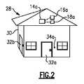
図2は、例示のドアベルスイッチのアプリケーション28を概略的に示す。家30は、ドア32aと、ドアベルボタンに組み込まれてドア32aに関連付けられた無線バッテリレスドアベルスイッチ34aとを含む。ドア32aは家30への入口ドアとして示されているが、例えば、子供用ドア、ペット用ドア、地下室ドア、エレべータルーフドア、非常口ドア、又は高齢者用ドアのような他のドアが使用されてもよい。スイッチ34aはバッテリレスであり、太陽エネルギーを回収するべく動作可能である。または、スイッチ34aの作動から機械的エネルギーを回収するべく動作可能であってもよい。受信機14aは、照明負荷16a及び発音負荷18aに接続される。照明負荷16aは、受信機14aによって制御される家30内のシーリングライトのような標準的なライトに対応してよく、複数のライトに対応してもよい。発音負荷18aは、ドアベル音のような音声信号を発生するべく動作可能なスピーカに対応してよい。受信機14aがドアベルスイッチ34aから信号を受信すると、受信機14aはソフトウェアを使用して当該信号を処理し、照明負荷16aに関連付けられたライトをフラッシュさせるか又は音を発生する発音負荷18aを作動させることによりドア通知を与える。一例では、ドア通知は、照明負荷16aのフラッシュ及び発音負荷18aからの音を含む。受信機14aは標準の建物のライトを制御するべく動作可能であり、かつ、発音負荷18aを制御するので、このような態様での当該2つの相互接続が可能となる。また、家30は、第2ドア32bと、第2ドア32bに関連付けられた第2無線バッテリレスドアベルスイッチ34bとを含んでよい。また、スイッチ34bが、照明負荷16a及び発音負荷18aを作動させるべく動作可能であってもよい。 FIG. 2 schematically illustrates an exemplary
図3は、例示のドアノッカースイッチのアプリケーション38を概略的に示す。家40は、ドア32cと、ドア32cに関連付けられたドアノッカースイッチ42とを含む。この例では、ドアノッカースイッチ42は、機械的エネルギー回収器44に接続される。機械的エネルギー回収器44は、ドアノッカースイッチ42の動きからエネルギーを回収するべく動作可能である。一例のエネルギー回収器がEnOceanから製品番号ECO100として入手可能である。ドアノッカースイッチ42は、受信機14bに信号を送信するべく作動する。受信機14bは、照明負荷16b及び発音負荷18bに接続される。受信機14bがドアノッカースイッチ42から信号を受信すると、受信機14bはソフトウェアを使用して当該信号を処理し、照明負荷16aをフラッシュさせる又は発音負荷18aを作動させるといったドア通知を与える。前述の例のように、ライト16は、シーリングライトのような標準の建物のライトであってよい。 FIG. 3 schematically illustrates an exemplary door
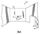
図4は、可動受信機ユニット50を概略的に示す。図4に示されるように、可動受信機ユニット50は、家60の壁54のコンセント52に差し込まれてよい。この例では、可動受信機ユニット50が受信機として動作する。発音負荷18cが可動受信機ユニット50に組み込まれる。ドア32dの無線バッテリレスドアベルスイッチ34が作動すると、ドアベルスイッチ34cは可動受信機ユニット50に信号を送信する。可動受信器ユニット50は、当該信号に応答して、ソフトウェアを使用して当該信号を処理し可動受信機ユニット50内のドアベルを作動させる。人が、家中で可動受信機50を持ち歩いてよい。また、可動受信機ユニット50を異なるコンセントに差し込んでもよい。これにより、ドアベルスイッチ34cが作動した場合に人が家内の離れたところにいても、ドアベル音のような音がなおも可聴となる。 FIG. 4 schematically shows the
なお、家30、40、60は、複数のドアベルスイッチ34、複数のドアノッカースイッチ42、複数の照明負荷16、複数の発音負荷18、又は複数の可動受信機を含んでよい。受信機14は、複数のドアベルスイッチ及び複数のドアノッカースイッチに応答するべくプログラムされてよい。発音負荷18が、例えば異なる着信音のような異なる音を鳴らすことができる場合、受信機14、50は、どのスイッチが作動したかに基づいて又はスイッチからのクリックパターンに基づいて異なる音を作動させるべくプログラムされてよい。例えば、図2に示されるように、家30は、第1ドアベルスイッチ34a及び第2ドアベルスイッチ34bを有する。発音負荷18aが異なる音を鳴らすことができる場合、受信機14aは、発音負荷18aに指令を与えるべくプログラムされてよい。これにより、第1ドアベルスイッチ34aが作動すると第1音が鳴り、第2ドアベルスイッチ34bが作動すると第2音が鳴る。 The
また、受信機14aは、スイッチ34aからの第1クリックパターンに応答して第1通知を与えるべくプログラムされてよく、スイッチ34aからの第2クリックパターンに応答して第2通知を与えるべくプログラムされてもよい。これにより、住宅所有者のような人が異なる個人へ異なるクリックパターンを与え、当該人は、その通知に基づいて誰がドアのところにいるかを特定することができる。 The
本発明の好ましい実施例が説明されたが、当業者であれば所定の修正例も本発明の範囲内に入ることがわかるだろう。したがって、本発明の真の範囲及び内容を決定するべく以下の特許請求の範囲が精査されるべきである。 While the preferred embodiment of the present invention has been described, those skilled in the art will recognize that certain modifications are within the scope of the present invention. Accordingly, the following claims should be reviewed to determine the true scope and content of this invention.
Claims (20)
Translated fromJapanese照明負荷、発音負荷、又はその双方に接続された受信機と
を含み、
前記受信機は、前記無線バッテリレススイッチからの信号に応答してドア通知を与えるべく動作可能であり、
前記ドア通知は、前記照明負荷のフラッシュ、前記発音負荷からの音、又はその双方を含むドア通知システム。A wireless batteryless switch associated with the door;
And a receiver connected to the lighting load, the sounding load, or both,
The receiver is operable to provide a door notification in response to a signal from the wireless batteryless switch;
The door notification includes a door notification system including a flash of the lighting load, a sound from the sound generation load, or both.
電気コンセントに差し込まれるべく動作可能であって、ビルトイン発音負荷を含む携帯可能受信機と
を含み、
前記携帯可能受信機は、前記発音負荷を作動させて前記無線バッテリレススイッチからの信号に応答して音声信号を生成するべく動作可能であるドア通知システム。A wireless batteryless switch associated with the door;
A portable receiver operable to be plugged into an electrical outlet and including a built-in sounding load;
The portable receiver is operable to generate a voice signal in response to a signal from the wireless batteryless switch by actuating the sounding load.
Applications Claiming Priority (3)
| Application Number | Priority Date | Filing Date | Title |
|---|---|---|---|
| US95400707P | 2007-08-05 | 2007-08-05 | |
| US60/954,007 | 2007-08-05 | ||
| PCT/US2008/070700WO2009020757A1 (en) | 2007-08-05 | 2008-07-22 | Door notification system |
Publications (2)
| Publication Number | Publication Date |
|---|---|
| JP2010535958Atrue JP2010535958A (en) | 2010-11-25 |
| JP5681858B2 JP5681858B2 (en) | 2015-03-11 |
Family
ID=39817133
Family Applications (5)
| Application Number | Title | Priority Date | Filing Date |
|---|---|---|---|
| JP2010520068APendingJP2011512044A (en) | 2007-08-05 | 2008-07-22 | Wireless energy self-sufficiency switch |
| JP2010520066AExpired - Fee RelatedJP5681858B2 (en) | 2007-08-05 | 2008-07-22 | Door notification system |
| JP2010520065AExpired - Fee RelatedJP5688490B2 (en) | 2007-08-05 | 2008-07-22 | Wireless switching application |
| JP2010520089APendingJP2010536247A (en) | 2007-08-05 | 2008-07-25 | Notification system using energy self-sufficiency switch |
| JP2013183904APendingJP2014014149A (en) | 2007-08-05 | 2013-09-05 | Notification system using energy self-supply switch |
Family Applications Before (1)
| Application Number | Title | Priority Date | Filing Date |
|---|---|---|---|
| JP2010520068APendingJP2011512044A (en) | 2007-08-05 | 2008-07-22 | Wireless energy self-sufficiency switch |
Family Applications After (3)
| Application Number | Title | Priority Date | Filing Date |
|---|---|---|---|
| JP2010520065AExpired - Fee RelatedJP5688490B2 (en) | 2007-08-05 | 2008-07-22 | Wireless switching application |
| JP2010520089APendingJP2010536247A (en) | 2007-08-05 | 2008-07-25 | Notification system using energy self-sufficiency switch |
| JP2013183904APendingJP2014014149A (en) | 2007-08-05 | 2013-09-05 | Notification system using energy self-supply switch |
Country Status (13)
| Country | Link |
|---|---|
| US (5) | US20110012541A1 (en) |
| EP (4) | EP2179407A1 (en) |
| JP (5) | JP2011512044A (en) |
| KR (4) | KR20100038410A (en) |
| CN (4) | CN101842817B (en) |
| AR (4) | AR068803A1 (en) |
| BR (4) | BRPI0814969A2 (en) |
| CA (4) | CA2693385A1 (en) |
| CL (4) | CL2008002305A1 (en) |
| MX (4) | MX2010001007A (en) |
| RU (4) | RU2010107737A (en) |
| WO (4) | WO2009020762A1 (en) |
| ZA (5) | ZA201000361B (en) |
Cited By (3)
| Publication number | Priority date | Publication date | Assignee | Title |
|---|---|---|---|---|
| JP2013062770A (en)* | 2011-09-15 | 2013-04-04 | Kawamura Electric Inc | Battery-less wireless switch system |
| JP2015033046A (en)* | 2013-08-05 | 2015-02-16 | 京セラドキュメントソリューションズ株式会社 | Operation control device, electronic apparatus, and image forming apparatus |
| KR20170026858A (en)* | 2015-08-31 | 2017-03-09 | 주식회사 아이콘트롤스 | Home-network system for Disabled |
Families Citing this family (68)
| Publication number | Priority date | Publication date | Assignee | Title |
|---|---|---|---|---|
| US8519566B2 (en)* | 2006-03-28 | 2013-08-27 | Wireless Environment, Llc | Remote switch sensing in lighting devices |
| CN101965752A (en)* | 2008-03-05 | 2011-02-02 | 马斯科公司 | User interface for wireless lighting control |
| JP4544338B2 (en)* | 2008-04-28 | 2010-09-15 | ソニー株式会社 | Power transmission device, power reception device, power transmission method, program, and power transmission system |
| US7839017B2 (en)* | 2009-03-02 | 2010-11-23 | Adura Technologies, Inc. | Systems and methods for remotely controlling an electrical load |
| US8275471B2 (en) | 2009-11-06 | 2012-09-25 | Adura Technologies, Inc. | Sensor interface for wireless control |
| US20100114340A1 (en)* | 2008-06-02 | 2010-05-06 | Charles Huizenga | Automatic provisioning of wireless control systems |
| US8364325B2 (en) | 2008-06-02 | 2013-01-29 | Adura Technologies, Inc. | Intelligence in distributed lighting control devices |
| CA2957199C (en) | 2008-11-26 | 2019-01-08 | Wireless Environment, Llc | Wireless lighting devices and applications |
| US8508148B1 (en)* | 2009-02-01 | 2013-08-13 | MagicLux, LLC | System for light and appliance remote control |
| FR2953059B1 (en)* | 2009-11-25 | 2011-11-04 | Schneider Electric Ind Sas | REMOTE CONTROL DEVICE |
| JP2013541156A (en)* | 2010-09-24 | 2013-11-07 | コーニンクレッカ フィリップス エヌ ヴェ | Tactile navigation of color temperature and light intensity |
| US8730046B2 (en)* | 2010-10-01 | 2014-05-20 | B&G Plastics, Inc. | EAS integrated faucet tag assembly |
| DE102011005336A1 (en)† | 2011-03-10 | 2012-09-13 | Zf Friedrichshafen Ag | hinge assembly |
| ITTO20110694A1 (en) | 2011-07-28 | 2011-10-27 | Torino Politecnico | SYSTEM OF INFOMOBILITY AND / OR SELF-ENHANCED DIAGNOSTICS AND HARVESTER DEVICE PERFECTED FOR SUPPLYING THIS SYSTEM |
| WO2013030361A1 (en)* | 2011-09-02 | 2013-03-07 | Msr-Solutions Gmbh | Home automation and/or home information system having a push-button unit |
| JP2013070520A (en) | 2011-09-22 | 2013-04-18 | Panasonic Corp | Driving method of non contact power supply device, non contact power supply device, and non contact power supply system |
| TWM425985U (en)* | 2011-11-11 | 2012-04-01 | Tuton Technology Co Ltd | Lamp holder module with wireless network sharing function |
| US9192019B2 (en) | 2011-12-07 | 2015-11-17 | Abl Ip Holding Llc | System for and method of commissioning lighting devices |
| US9046414B2 (en)* | 2012-09-21 | 2015-06-02 | Google Inc. | Selectable lens button for a hazard detector and method therefor |
| JP6121802B2 (en)* | 2012-10-12 | 2017-04-26 | 東芝ライフスタイル株式会社 | refrigerator |
| US9678548B1 (en)* | 2012-12-31 | 2017-06-13 | EMC IP Holding Company LLC | Powering security devices |
| US9948892B2 (en)* | 2013-07-17 | 2018-04-17 | BOT Home Automation, Inc. | Wireless speaker devices for wireless audio/video recording and communication devices |
| US10412487B2 (en) | 2013-07-17 | 2019-09-10 | Amazon Technologies, Inc. | Auto-provisioning of wireless speaker devices for audio/video recording and communication devices |
| AU2015220797B2 (en)* | 2014-02-19 | 2018-08-30 | Basf Se | Aqueous co-formulation of metalaxyl |
| KR102206179B1 (en)* | 2014-03-11 | 2021-01-22 | 삼성전자주식회사 | Refrigerator |
| DE102014011156A1 (en)* | 2014-07-25 | 2016-01-28 | Hella Kgaa Hueck & Co. | Method for wireless signal transmission and sensor-controlled component |
| US10531545B2 (en) | 2014-08-11 | 2020-01-07 | RAB Lighting Inc. | Commissioning a configurable user control device for a lighting control system |
| US9883567B2 (en) | 2014-08-11 | 2018-01-30 | RAB Lighting Inc. | Device indication and commissioning for a lighting control system |
| US10085328B2 (en) | 2014-08-11 | 2018-09-25 | RAB Lighting Inc. | Wireless lighting control systems and methods |
| US10039174B2 (en) | 2014-08-11 | 2018-07-31 | RAB Lighting Inc. | Systems and methods for acknowledging broadcast messages in a wireless lighting control network |
| US9366065B2 (en) | 2014-09-18 | 2016-06-14 | Vivint, Inc. | Hinge sensor for barrier |
| US10352734B2 (en) | 2014-09-18 | 2019-07-16 | Vivint, Inc. | Hinge sensor for barrier |
| US9990819B2 (en)* | 2014-09-18 | 2018-06-05 | Vivint, Inc. | Magnetic hinge sensor for barrier |
| US10438978B2 (en) | 2014-10-31 | 2019-10-08 | Sargent Manufacturing Company | Measuring harvested energy using an ultra-low duty cycle measurement system |
| US9526155B2 (en)* | 2014-12-30 | 2016-12-20 | Google Inc. | Systems and methods of controlling light sources according to location |
| US9628692B2 (en)* | 2015-05-13 | 2017-04-18 | Tyco Fire & Security Gmbh | Self-powered door and window opening sensor |
| US10578802B2 (en) | 2015-06-15 | 2020-03-03 | Nec Corporation | Pluggable optical module and optical communication system |
| US9911290B1 (en) | 2015-07-25 | 2018-03-06 | Gary M. Zalewski | Wireless coded communication (WCC) devices for tracking retail interactions with goods and association to user accounts |
| US10355730B1 (en) | 2015-07-25 | 2019-07-16 | Gary M. Zalewski | Wireless coded communication (WCC) devices with power harvesting power sources for processing internet purchase transactions |
| CN105116753A (en)* | 2015-09-18 | 2015-12-02 | 李林国 | Smart home based on Internet of Things |
| CA3013667C (en)* | 2016-03-21 | 2022-10-25 | Sargent Manufacturing Company | Measuring harvested energy using an ultra-low duty cycle measurement system |
| CA2961090A1 (en) | 2016-04-11 | 2017-10-11 | Tti (Macao Commercial Offshore) Limited | Modular garage door opener |
| USD841444S1 (en) | 2016-04-11 | 2019-02-26 | Tti (Macao Commercial Offshore) Limited | Accessory mount |
| USD871472S1 (en) | 2016-04-11 | 2019-12-31 | Tti (Macao Commercial Offshore) Limited | Garage door opener |
| CA2961221A1 (en) | 2016-04-11 | 2017-10-11 | Tti (Macao Commercial Offshore) Limited | Modular garage door opener |
| CN106201418A (en)* | 2016-06-27 | 2016-12-07 | 捷开通讯(深圳)有限公司 | The audio method of adjustment of intelligent mobile terminal and intelligent mobile terminal |
| US9923514B1 (en)* | 2017-01-26 | 2018-03-20 | Face International Corporation | Security and tracking systems including energy harvesting components for providing autonomous electrical power |
| US11310637B2 (en) | 2017-01-26 | 2022-04-19 | Face International Corporation | Methods for producing security and tracking systems including energy harvesting components for providing autonomous electrical power |
| EP3580732A4 (en) | 2017-02-08 | 2020-12-09 | The Lockout Co., LLC | Building lockdown system |
| US10410492B2 (en) | 2017-09-18 | 2019-09-10 | Comcast Cable Communications, Llc | Automatic presence simulator for security systems |
| JP6980259B2 (en) | 2017-09-25 | 2021-12-15 | 下西技研工業株式会社 | Hinge and hinge monitoring method |
| JP7283721B2 (en) | 2017-09-25 | 2023-05-30 | 下西技研工業株式会社 | Hinge and how to monitor the hinge |
| US10251242B1 (en) | 2017-10-04 | 2019-04-02 | Resilience Magnum IP, LLC | Information and hub lights |
| US10574757B2 (en) | 2017-10-04 | 2020-02-25 | Resilience Magnum IP, LLC | Self aware lights that self-configure |
| US10867486B2 (en)* | 2017-10-04 | 2020-12-15 | Resilience Magnum IP, LLC | Hospitality light |
| US10510251B2 (en) | 2017-10-04 | 2019-12-17 | Resilience Magnum IP, LLC | Parking space light |
| US11244563B2 (en) | 2017-10-04 | 2022-02-08 | Resilience Magnum IP, LLC | Flow management light |
| US10408988B2 (en) | 2017-10-04 | 2019-09-10 | Resilience Magnum IP, LLC | Techniques for enhanced diffusion lighting |
| US10794603B2 (en) | 2017-10-04 | 2020-10-06 | Resilience Magnum IP, LLC | Intelligent purifier light |
| US11596118B2 (en) | 2017-10-04 | 2023-03-07 | Resilience Magnum IP, LLC | Intelligent horticulture light |
| US10677402B2 (en) | 2017-10-04 | 2020-06-09 | Resilience Magnum IP, LLC | Lighting drywall |
| CN107845215A (en)* | 2017-10-30 | 2018-03-27 | 四川金网通电子科技有限公司 | The wireless doorbell system and wireless doorbell matching method of a kind of electronic lock |
| US10798801B2 (en)* | 2018-06-26 | 2020-10-06 | Charter Communications Operating, Llc | Universal smart switch management |
| US11095153B2 (en) | 2019-03-15 | 2021-08-17 | Ossia Inc. | Wireless power system technology implemented in lighting infrastructure |
| US11412187B2 (en) | 2019-10-21 | 2022-08-09 | Alarm.Com Incorporated | Batteryless video doorbell |
| US11514764B2 (en) | 2019-11-21 | 2022-11-29 | Alarm.Com Incorporated | Smartlock system for improved fire safety |
| JP7503752B2 (en)* | 2020-03-05 | 2024-06-21 | パナソニックIpマネジメント株式会社 | Information processing system and information processing method |
| CN111315098B (en)* | 2020-04-09 | 2022-07-19 | 三一重机有限公司 | Night lighting control system and method |
Citations (8)
| Publication number | Priority date | Publication date | Assignee | Title |
|---|---|---|---|---|
| JPS63135488U (en)* | 1987-02-24 | 1988-09-06 | ||
| JPH0353296A (en)* | 1989-07-21 | 1991-03-07 | Nishi Michio | Door chime device |
| JPH1139573A (en)* | 1997-07-15 | 1999-02-12 | Yutaka Aono | Visitor notification device for the visually impaired |
| JP3058722U (en)* | 1998-10-27 | 1999-06-22 | 船井電機株式会社 | Mecha chime notification device |
| JP2000057882A (en)* | 1998-08-04 | 2000-02-25 | Maruyasu Industries Co Ltd | Mat device |
| JP2002118480A (en)* | 2000-10-10 | 2002-04-19 | Seiko Epson Corp | Radio communication equipment |
| JP2004350019A (en)* | 2003-05-22 | 2004-12-09 | Hitachi Ltd | Switch terminal having power generation unit and method of using switch terminal having power generation unit |
| JP2005130395A (en)* | 2003-10-27 | 2005-05-19 | Usc Corp | Wireless remote control apparatus |
Family Cites Families (109)
| Publication number | Priority date | Publication date | Assignee | Title |
|---|---|---|---|---|
| US3614760A (en)* | 1968-12-27 | 1971-10-19 | Arthur L Zimmer | Signaling apparatus |
| US3860872A (en)* | 1970-02-05 | 1975-01-14 | Pye Ltd | Multiple receiver selection system |
| US3781836A (en)* | 1972-07-14 | 1973-12-25 | Westinghouse Electric Corp | Self-powered wireless intrusion alarm system |
| US3827038A (en)* | 1972-10-26 | 1974-07-30 | Solid State Technology | Alarm system |
| US3980996A (en)* | 1973-09-12 | 1976-09-14 | Myron Greenspan | Self-sustaining alarm transmitter device |
| US4150265A (en)* | 1977-03-14 | 1979-04-17 | Buildex Incorporated | Hinge-activated switch |
| US4365238A (en)* | 1979-06-08 | 1982-12-21 | Adam Kollin | Visual signalling apparatus |
| JPS57147599U (en)* | 1981-03-11 | 1982-09-16 | ||
| US4400696A (en)* | 1981-04-29 | 1983-08-23 | Klingensmith Robert R | Animal actuated attention attracting apparatus |
| US4538139A (en)* | 1982-04-30 | 1985-08-27 | Bolt Beranek And Newman Inc. | Signalling apparatus |
| JPS6084693A (en)* | 1983-10-15 | 1985-05-14 | 松下電工株式会社 | Wireless monitor |
| JPS6073595U (en)* | 1983-10-27 | 1985-05-23 | 株式会社トミー | Switching device for toys |
| JPS60184188U (en)* | 1984-05-15 | 1985-12-06 | 三洋電機株式会社 | visitor alarm |
| JPS645296A (en)* | 1987-06-29 | 1989-01-10 | Sanyo Electric Co | Remote control device |
| US5099193A (en)* | 1987-07-30 | 1992-03-24 | Lutron Electronics Co., Inc. | Remotely controllable power control system |
| US5237264A (en)* | 1987-07-30 | 1993-08-17 | Lutron Electronics Co., Inc. | Remotely controllable power control system |
| US5146153A (en)* | 1987-07-30 | 1992-09-08 | Luchaco David G | Wireless control system |
| JPH01126095U (en)* | 1988-02-23 | 1989-08-29 | ||
| JPH0360800U (en)* | 1989-10-19 | 1991-06-14 | ||
| JPH0446495A (en)* | 1990-06-13 | 1992-02-17 | Sony Corp | Remote commander |
| JPH0473292U (en)* | 1990-10-26 | 1992-06-26 | ||
| US5191265A (en)* | 1991-08-09 | 1993-03-02 | Lutron Electronics Co., Inc. | Wall mounted programmable modular control system |
| JPH07506738A (en)* | 1992-03-13 | 1995-07-27 | アレクサンダー,ゲイリー・イー | birth aid device |
| JPH0587894U (en)* | 1992-04-27 | 1993-11-26 | 弘 松岡 | Wireless auto switch in toilets |
| US5586048A (en)* | 1992-06-16 | 1996-12-17 | Vigilight Inc. | Intelligent wall switch |
| CN2161981Y (en)* | 1992-08-18 | 1994-04-13 | 吴忠华 | Wireless mutual interlocking switch |
| US5317303A (en)* | 1992-09-11 | 1994-05-31 | Anro Engineering, Inc. | Batteryless sensor used in security applications |
| JPH06133365A (en)* | 1992-10-15 | 1994-05-13 | Sony Corp | Wireless electric equipment |
| US5455464A (en)* | 1992-12-22 | 1995-10-03 | Firstperson, Inc. | Method and apparatus for providing dynamically configurable electrical switches |
| FI95326C (en) | 1993-12-03 | 1996-01-10 | Helvar Oy | Method and device for wireless remote control |
| DE69515204T2 (en)* | 1994-05-13 | 2000-10-12 | Fred M Schildwachter & Sons, Inc. | Combined audible and visual signaling device |
| EP0799461B1 (en)* | 1994-11-29 | 2001-10-31 | Simon K. C. Yung | Infrared motion detector with 180-degree detecting range |
| US5572190A (en)* | 1995-03-22 | 1996-11-05 | Anro Engineering, Inc. | Batteryless sensor used in security applications |
| US5475369A (en)* | 1995-05-24 | 1995-12-12 | Baker; William J. | Animal actuating signaling device |
| GB2308910A (en)* | 1996-01-02 | 1997-07-09 | Bernard John Regan | Lighting control |
| JPH09259367A (en)* | 1996-03-26 | 1997-10-03 | Nippon Rotsukusaabisu:Kk | Burglar prevention system |
| US6828909B2 (en) | 1996-05-30 | 2004-12-07 | Guardit Technologies Llc | Portable motion detector and alarm system and method |
| JPH11122680A (en)* | 1997-10-16 | 1999-04-30 | Matsushita Electric Works Ltd | Wireless remote control system |
| DE69910161T2 (en)* | 1998-05-20 | 2004-06-09 | Koninklijke Philips Electronics N.V. | DEVICE FOR RECEIVING SIGNALS |
| US6259372B1 (en)* | 1999-01-22 | 2001-07-10 | Eaton Corporation | Self-powered wireless transducer |
| US6275277B1 (en)* | 1999-05-17 | 2001-08-14 | Colorado Microdisplay, Inc. | Micro liquid crystal displays having a circular cover glass and a viewing area free of spacers |
| JP2001103061A (en)* | 1999-09-29 | 2001-04-13 | Hitachi Kokusai Electric Inc | Information communication equipment in accommodation facilities |
| JP2001224078A (en) | 1999-12-02 | 2001-08-17 | Yohachiro Hori | Remote control system, and its control method |
| US6445302B2 (en)* | 2000-02-14 | 2002-09-03 | Anthony Vena | Pet wireless doorbell device |
| JP2001320336A (en)* | 2000-05-08 | 2001-11-16 | Seiko Precision Inc | Data transmission device, nurse call transmitter, and nurse call system |
| JP2002015380A (en)* | 2000-06-28 | 2002-01-18 | Oga Kensetsu Kk | Crime prevention sensor-buried fitting structure |
| US6630894B1 (en)* | 2000-07-14 | 2003-10-07 | Face International Corp. | Self-powered switching device |
| US6882128B1 (en)* | 2000-09-27 | 2005-04-19 | Science Applications International Corporation | Method and system for energy reclamation and reuse |
| US20020070635A1 (en) | 2000-10-13 | 2002-06-13 | Morrison Gerald O. | Self-powered wireless switch |
| US6700310B2 (en)* | 2000-10-13 | 2004-03-02 | Lear Corporation | Self-powered wireless switch |
| JP2002142269A (en) | 2000-10-30 | 2002-05-17 | Matsushita Electric Works Ltd | Wireless switch system |
| US6715730B2 (en)* | 2000-12-27 | 2004-04-06 | Jerry A. Ehr | Security water control |
| DE10103952A1 (en)* | 2001-01-30 | 2002-10-02 | Enocean Gmbh | Device for supplying energy to a sensor |
| US6776334B1 (en)* | 2001-02-22 | 2004-08-17 | Advanced Micro Devices, Inc. | System and method for determining the location of a mobile device within a wireless network |
| FR2826204B1 (en)* | 2001-06-15 | 2003-09-19 | Legrand Sa | USE OF A PIEZO-ACTIVE BODY AS WELL AS APPARATUS AND SYSTEM COMPRISING SAME |
| AU2002320270B2 (en)* | 2001-07-03 | 2008-06-05 | Clark Davis Boyd | Self-powered switch initiation system |
| US6832072B2 (en)* | 2001-08-31 | 2004-12-14 | Inncom International, Inc. | Wireless switch |
| JP4335485B2 (en)* | 2001-09-28 | 2009-09-30 | 美恵子 露崎 | Control device |
| DE10155125B4 (en)* | 2001-11-09 | 2004-07-15 | Enocean Gmbh | Device for converting mechanical energy into electrical energy |
| US6737969B2 (en)* | 2001-11-27 | 2004-05-18 | Ion Digital Llp | Wireless security sensor systems for windows and doors |
| US6478603B1 (en)* | 2001-12-24 | 2002-11-12 | Hon Hai Precision Ind. Co., Ltd. | Electrical connector with mechanically reinforced blind mating guides |
| US6775523B2 (en)* | 2002-01-03 | 2004-08-10 | Desa Ip, Llc | Wireless transmitter and doorbell system |
| JP2003224315A (en)* | 2002-01-30 | 2003-08-08 | Sony Corp | Power generation device, power supply device, remote control device, and electronic equipment |
| US7256505B2 (en)* | 2003-03-05 | 2007-08-14 | Microstrain, Inc. | Shaft mounted energy harvesting for wireless sensor operation and data transmission |
| JP3915577B2 (en)* | 2002-04-05 | 2007-05-16 | 松下電工株式会社 | Open / close detection sensor |
| US7082339B2 (en)* | 2002-04-17 | 2006-07-25 | Black & Decker Inc. | Home automation system |
| US6778086B2 (en)* | 2002-05-02 | 2004-08-17 | Gerald Angelo Morrone | Open window security lock |
| DE10221420A1 (en)* | 2002-05-14 | 2003-12-11 | Enocean Gmbh | Device for converting mechanical energy into electrical energy |
| JP3947802B2 (en)* | 2002-08-30 | 2007-07-25 | 株式会社ユーエスシー | Building closure |
| DE10256156A1 (en)* | 2002-10-04 | 2004-04-15 | Enocean Gmbh | Power self-sufficient type electromechanical push-button radio switch, includes electronics unit for generating and sending radio signal |
| DE10301678B4 (en)* | 2003-01-17 | 2005-02-24 | Enocean Gmbh | sensor |
| US7081816B2 (en)* | 2003-06-06 | 2006-07-25 | Ion Digital Llp | Compact wireless sensor |
| JP3908207B2 (en)* | 2003-07-17 | 2007-04-25 | 伊藤忠丸紅テクノスチール株式会社 | Crescent handle cap and crime prevention system using the crescent handle cap |
| CA2476947C (en)* | 2003-08-07 | 2012-11-13 | Joerg C. Wagner | Method and apparatus for asset tracking and room monitoring in establishments having multiple rooms for temporary occupancy |
| JP3894179B2 (en)* | 2003-10-02 | 2007-03-14 | トヨタ自動車株式会社 | Fuel supply device for internal combustion engine |
| US7321301B2 (en) | 2003-10-02 | 2008-01-22 | Honeywell International, Inc. | Wireless children's safety light in a security system |
| JP2005126996A (en)* | 2003-10-23 | 2005-05-19 | Nabtesco Corp | Simple security system for automatic doors |
| US7161276B2 (en)* | 2003-10-24 | 2007-01-09 | Face International Corp. | Self-powered, electronic keyed, multifunction switching system |
| US6952165B2 (en)* | 2003-12-19 | 2005-10-04 | Honeywell International, Inc. | Concealed wireless sensor with external antenna |
| US7122944B2 (en)* | 2004-01-16 | 2006-10-17 | Tangidyne Corporation | Signal generation system and method for generating signals |
| JP2005322008A (en)* | 2004-05-10 | 2005-11-17 | Hitachi Ltd | Intruder monitoring system and intruder monitoring method |
| US7692559B2 (en)* | 2004-06-19 | 2010-04-06 | Face International Corp | Self-powered switch initiation system |
| WO2006009540A1 (en)* | 2004-06-19 | 2006-01-26 | Face Bradbury R | Self-powered switch initiation system |
| JP2006009280A (en)* | 2004-06-22 | 2006-01-12 | Usc Corp | Remote controller for sanitary washing apparatus |
| US20060012317A1 (en)* | 2004-07-14 | 2006-01-19 | Shin-Yung Chiu | RF remote dimmer controller |
| JP2006037344A (en)* | 2004-07-22 | 2006-02-09 | Matsushita Electric Ind Co Ltd | Electric lock control device and program |
| US20060033597A1 (en)* | 2004-08-11 | 2006-02-16 | Wells James D | Wireless safety alarm with enlarged actuator button |
| US7656308B2 (en)* | 2004-10-28 | 2010-02-02 | Heathco Llc | AC powered wireless control 3-way light switch transmitter |
| JP2006235724A (en)* | 2005-02-22 | 2006-09-07 | Matsushita Electric Ind Co Ltd | Crime prevention system |
| JP4694861B2 (en)* | 2005-02-28 | 2011-06-08 | アイホン株式会社 | Nursing support system |
| JP4732785B2 (en)* | 2005-04-21 | 2011-07-27 | セイコーインスツル株式会社 | Security system and slave station management method |
| JP5030943B2 (en) | 2005-04-22 | 2012-09-19 | コーニンクレッカ フィリップス エレクトロニクス エヌ ヴィ | Lighting device control method and control system |
| JP2006333049A (en) | 2005-05-26 | 2006-12-07 | Sony Computer Entertainment Inc | Remote controller, control method for remote controller, and program |
| US7498952B2 (en)* | 2005-06-06 | 2009-03-03 | Lutron Electronics Co., Inc. | Remote control lighting control system |
| CN101194219A (en)* | 2005-06-08 | 2008-06-04 | 鲍尔卡斯特公司 | Powering Units Using RF Energy Harvesting |
| US7142123B1 (en)* | 2005-09-23 | 2006-11-28 | Lawrence Kates | Method and apparatus for detecting moisture in building materials |
| JP2007104175A (en)* | 2005-10-03 | 2007-04-19 | Sharp Corp | Remote control device |
| US7733224B2 (en)* | 2006-06-30 | 2010-06-08 | Bao Tran | Mesh network personal emergency response appliance |
| DE102005059538B4 (en)* | 2005-12-13 | 2018-08-23 | Asm Automation Sensorik Messtechnik Gmbh | Hinge sensor |
| EP1967046B1 (en) | 2005-12-22 | 2018-02-21 | Philips Lighting Holding B.V. | A system and method for controlling lighting systems |
| US20070182543A1 (en)* | 2006-02-04 | 2007-08-09 | Hongyue Luo | Intelligent Home Security System |
| US9338839B2 (en)* | 2006-03-28 | 2016-05-10 | Wireless Environment, Llc | Off-grid LED power failure lights |
| US7724147B2 (en)* | 2006-07-13 | 2010-05-25 | Cardinal Health 303, Inc. | Medical notification apparatus and method |
| US20080070652A1 (en)* | 2006-09-18 | 2008-03-20 | Igt, Inc. | Reduced power consumption wager gaming machine |
| US8588103B2 (en)* | 2007-04-10 | 2013-11-19 | Control4 Corporation | System and method for distributing communications through a dense mesh network |
| US8274383B2 (en)* | 2008-03-31 | 2012-09-25 | The Boeing Company | Methods and systems for sensing activity using energy harvesting devices |
| CA2957199C (en)* | 2008-11-26 | 2019-01-08 | Wireless Environment, Llc | Wireless lighting devices and applications |
| US8277073B2 (en)* | 2009-01-21 | 2012-10-02 | Wells William K | Portable light apparatus and method of attachment |
| US20100253156A1 (en)* | 2009-04-07 | 2010-10-07 | Jeffrey Iott | Sensor device powered through rf harvesting |
- 2008
- 2008-07-22BRBRPI0814969-0A2Apatent/BRPI0814969A2/ennot_activeIP Right Cessation
- 2008-07-22EPEP08796392Apatent/EP2179407A1/ennot_activeWithdrawn
- 2008-07-22WOPCT/US2008/070720patent/WO2009020762A1/enactiveApplication Filing
- 2008-07-22RURU2010107737/08Apatent/RU2010107737A/enunknown
- 2008-07-22USUS12/667,909patent/US20110012541A1/ennot_activeAbandoned
- 2008-07-22USUS12/667,921patent/US8786435B2/enactiveActive
- 2008-07-22MXMX2010001007Apatent/MX2010001007A/ennot_activeApplication Discontinuation
- 2008-07-22KRKR1020107002092Apatent/KR20100038410A/ennot_activeWithdrawn
- 2008-07-22CNCN2008801020594Apatent/CN101842817B/ennot_activeExpired - Fee Related
- 2008-07-22EPEP08782182Apatent/EP2179406A1/ennot_activeWithdrawn
- 2008-07-22CNCN200880102060Apatent/CN101772788A/enactivePending
- 2008-07-22KRKR1020107002410Apatent/KR20100039876A/ennot_activeWithdrawn
- 2008-07-22CACA2693385Apatent/CA2693385A1/ennot_activeAbandoned
- 2008-07-22JPJP2010520068Apatent/JP2011512044A/enactivePending
- 2008-07-22RURU2010107739/07Apatent/RU2010107739A/ennot_activeApplication Discontinuation
- 2008-07-22EPEP08796391Apatent/EP2177086A1/ennot_activeCeased
- 2008-07-22JPJP2010520066Apatent/JP5681858B2/ennot_activeExpired - Fee Related
- 2008-07-22WOPCT/US2008/070700patent/WO2009020757A1/enactiveApplication Filing
- 2008-07-22CNCN200880102056Apatent/CN101810057A/enactivePending
- 2008-07-22MXMX2010001008Apatent/MX2010001008A/enactiveIP Right Grant
- 2008-07-22MXMX2010001010Apatent/MX2010001010A/enactiveIP Right Grant
- 2008-07-22JPJP2010520065Apatent/JP5688490B2/ennot_activeExpired - Fee Related
- 2008-07-22BRBRPI0814970-4A2Apatent/BRPI0814970A2/ennot_activeIP Right Cessation
- 2008-07-22RURU2010107738/08Apatent/RU2010107738A/enunknown
- 2008-07-22BRBRPI0814834-1Apatent/BRPI0814834A2/ennot_activeIP Right Cessation
- 2008-07-22KRKR1020107002093Apatent/KR20100042633A/ennot_activeWithdrawn
- 2008-07-22CACA2693386Apatent/CA2693386A1/ennot_activeAbandoned
- 2008-07-22CACA2693387Apatent/CA2693387A1/ennot_activeAbandoned
- 2008-07-22WOPCT/US2008/070699patent/WO2009020756A1/enactiveApplication Filing
- 2008-07-22USUS12/667,949patent/US20110012730A1/ennot_activeAbandoned
- 2008-07-25BRBRPI0814842-2Apatent/BRPI0814842A2/ennot_activeIP Right Cessation
- 2008-07-25MXMX2010001009Apatent/MX2010001009A/ennot_activeApplication Discontinuation
- 2008-07-25KRKR1020107002094Apatent/KR20100044191A/ennot_activeWithdrawn
- 2008-07-25WOPCT/US2008/071120patent/WO2009020775A1/enactiveApplication Filing
- 2008-07-25USUS12/667,934patent/US20110006893A1/ennot_activeAbandoned
- 2008-07-25RURU2010107740/08Apatent/RU2010107740A/enunknown
- 2008-07-25CACA2693299Apatent/CA2693299A1/ennot_activeAbandoned
- 2008-07-25USUS12/667,959patent/US8829809B2/enactiveActive
- 2008-07-25EPEP08796593.5Apatent/EP2177087B1/ennot_activeNot-in-force
- 2008-07-25JPJP2010520089Apatent/JP2010536247A/enactivePending
- 2008-07-25CNCN200880102069Apatent/CN101772991A/enactivePending
- 2008-08-04ARARP080103399Apatent/AR068803A1/enunknown
- 2008-08-04ARARP080103401Apatent/AR068805A1/enunknown
- 2008-08-04ARARP080103400Apatent/AR068804A1/enunknown
- 2008-08-04ARARP080103398Apatent/AR068979A1/enunknown
- 2008-08-05CLCL2008002305Apatent/CL2008002305A1/enunknown
- 2008-08-05CLCL2008002301Apatent/CL2008002301A1/enunknown
- 2008-08-05CLCL2008002304Apatent/CL2008002304A1/enunknown
- 2008-08-05CLCL2008002303Apatent/CL2008002303A1/enunknown
- 2010
- 2010-01-18ZAZA201000361Apatent/ZA201000361B/enunknown
- 2010-01-18ZAZA201000363Apatent/ZA201000363B/enunknown
- 2010-01-18ZAZA201000362Apatent/ZA201000362B/enunknown
- 2010-01-25ZAZA201000553Apatent/ZA201000553B/enunknown
- 2010-01-25ZAZA201000554Apatent/ZA201000554B/enunknown
- 2013
- 2013-09-05JPJP2013183904Apatent/JP2014014149A/enactivePending
Patent Citations (8)
| Publication number | Priority date | Publication date | Assignee | Title |
|---|---|---|---|---|
| JPS63135488U (en)* | 1987-02-24 | 1988-09-06 | ||
| JPH0353296A (en)* | 1989-07-21 | 1991-03-07 | Nishi Michio | Door chime device |
| JPH1139573A (en)* | 1997-07-15 | 1999-02-12 | Yutaka Aono | Visitor notification device for the visually impaired |
| JP2000057882A (en)* | 1998-08-04 | 2000-02-25 | Maruyasu Industries Co Ltd | Mat device |
| JP3058722U (en)* | 1998-10-27 | 1999-06-22 | 船井電機株式会社 | Mecha chime notification device |
| JP2002118480A (en)* | 2000-10-10 | 2002-04-19 | Seiko Epson Corp | Radio communication equipment |
| JP2004350019A (en)* | 2003-05-22 | 2004-12-09 | Hitachi Ltd | Switch terminal having power generation unit and method of using switch terminal having power generation unit |
| JP2005130395A (en)* | 2003-10-27 | 2005-05-19 | Usc Corp | Wireless remote control apparatus |
Cited By (4)
| Publication number | Priority date | Publication date | Assignee | Title |
|---|---|---|---|---|
| JP2013062770A (en)* | 2011-09-15 | 2013-04-04 | Kawamura Electric Inc | Battery-less wireless switch system |
| JP2015033046A (en)* | 2013-08-05 | 2015-02-16 | 京セラドキュメントソリューションズ株式会社 | Operation control device, electronic apparatus, and image forming apparatus |
| KR20170026858A (en)* | 2015-08-31 | 2017-03-09 | 주식회사 아이콘트롤스 | Home-network system for Disabled |
| KR101720762B1 (en)* | 2015-08-31 | 2017-04-03 | 주식회사 아이콘트롤스 | Home-network system for Disabled |
Also Published As
Similar Documents
| Publication | Publication Date | Title |
|---|---|---|
| JP5681858B2 (en) | Door notification system | |
| US11545171B2 (en) | Voice responsive in-wall device | |
| US10134305B2 (en) | Navigation system | |
| TW201516984A (en) | A smoke detector with enhanced audio and communications capabilities | |
| CN105035891B (en) | Elevator intelligent calling system and its control method | |
| JP2020020259A (en) | Automatic door system for toilet, voice guidance device, voice guidance method | |
| KR101678396B1 (en) | Call System for deaf person | |
| JP2004062548A (en) | Security alarm device using an electric door | |
| HK1141618A (en) | Door notification system | |
| JP2009076252A (en) | Sensor light | |
| JP2004047346A (en) | Lighting control system | |
| KR200405228Y1 (en) | Light Control with Sensor | |
| CN215341308U (en) | A wireless lighting remote control based on electronic technology | |
| JP3112659U (en) | Guard dog | |
| JP2009290350A (en) | Intercom system and intercom master set | |
| JP5957776B2 (en) | Intercom system | |
| KR20250102677A (en) | LED indoor lighting system with loT-based life-friendly communication function added | |
| JP2017174566A (en) | Apparatus control system | |
| BE1022734B1 (en) | PROFILE FOR DOOR OR WALL PANELS | |
| JP2024058516A (en) | Emergency Broadcast System | |
| JP2009111528A (en) | Intercom device | |
| JP6319783B2 (en) | Lighting unit | |
| KR20090020063A (en) | Elevator system to guide the timeout during waiting in connection with the waiting situation | |
| JP2015114824A (en) | Rescue device, rescue method, and rescue system | |
| ITMI980625U1 (en) | VOCAL BELL |
Legal Events
| Date | Code | Title | Description |
|---|---|---|---|
| A621 | Written request for application examination | Free format text:JAPANESE INTERMEDIATE CODE: A621 Effective date:20110602 | |
| A977 | Report on retrieval | Free format text:JAPANESE INTERMEDIATE CODE: A971007 Effective date:20121126 | |
| A131 | Notification of reasons for refusal | Free format text:JAPANESE INTERMEDIATE CODE: A131 Effective date:20121219 | |
| A601 | Written request for extension of time | Free format text:JAPANESE INTERMEDIATE CODE: A601 Effective date:20130318 | |
| A602 | Written permission of extension of time | Free format text:JAPANESE INTERMEDIATE CODE: A602 Effective date:20130326 | |
| A521 | Request for written amendment filed | Free format text:JAPANESE INTERMEDIATE CODE: A523 Effective date:20130607 | |
| A131 | Notification of reasons for refusal | Free format text:JAPANESE INTERMEDIATE CODE: A131 Effective date:20131203 | |
| A521 | Request for written amendment filed | Free format text:JAPANESE INTERMEDIATE CODE: A523 Effective date:20140219 | |
| TRDD | Decision of grant or rejection written | ||
| A01 | Written decision to grant a patent or to grant a registration (utility model) | Free format text:JAPANESE INTERMEDIATE CODE: A01 Effective date:20140715 | |
| A601 | Written request for extension of time | Free format text:JAPANESE INTERMEDIATE CODE: A601 Effective date:20140812 | |
| A602 | Written permission of extension of time | Free format text:JAPANESE INTERMEDIATE CODE: A602 Effective date:20140818 | |
| A711 | Notification of change in applicant | Free format text:JAPANESE INTERMEDIATE CODE: A711 Effective date:20140908 | |
| A61 | First payment of annual fees (during grant procedure) | Free format text:JAPANESE INTERMEDIATE CODE: A61 Effective date:20140908 | |
| R150 | Certificate of patent or registration of utility model | Ref document number:5681858 Country of ref document:JP Free format text:JAPANESE INTERMEDIATE CODE: R150 | |
| R250 | Receipt of annual fees | Free format text:JAPANESE INTERMEDIATE CODE: R250 | |
| R250 | Receipt of annual fees | Free format text:JAPANESE INTERMEDIATE CODE: R250 | |
| R250 | Receipt of annual fees | Free format text:JAPANESE INTERMEDIATE CODE: R250 | |
| R250 | Receipt of annual fees | Free format text:JAPANESE INTERMEDIATE CODE: R250 | |
| R250 | Receipt of annual fees | Free format text:JAPANESE INTERMEDIATE CODE: R250 | |
| R250 | Receipt of annual fees | Free format text:JAPANESE INTERMEDIATE CODE: R250 | |
| LAPS | Cancellation because of no payment of annual fees |