JP2010535570A - Automatic identification of the responsible coronary artery - Google Patents
Automatic identification of the responsible coronary arteryDownload PDFInfo
- Publication number
- JP2010535570A JP2010535570AJP2010519556AJP2010519556AJP2010535570AJP 2010535570 AJP2010535570 AJP 2010535570AJP 2010519556 AJP2010519556 AJP 2010519556AJP 2010519556 AJP2010519556 AJP 2010519556AJP 2010535570 AJP2010535570 AJP 2010535570A
- Authority
- JP
- Japan
- Prior art keywords
- lead
- coronary artery
- ecg
- leads
- elevation
- Prior art date
- Legal status (The legal status is an assumption and is not a legal conclusion. Google has not performed a legal analysis and makes no representation as to the accuracy of the status listed.)
- Granted
Links
- 210000004351coronary vesselAnatomy0.000titleclaimsabstractdescription102
- 238000000034methodMethods0.000claimsabstractdescription28
- 230000000302ischemic effectEffects0.000claimsabstractdescription10
- 230000001154acute effectEffects0.000claimsabstractdescription9
- 230000000694effectsEffects0.000claimsabstractdescription9
- 230000007423decreaseEffects0.000claimsdescription14
- 230000015556catabolic processEffects0.000claimsdescription9
- 238000006731degradation reactionMethods0.000claimsdescription9
- 230000009467reductionEffects0.000claimsdescription5
- 206010000891acute myocardial infarctionDiseases0.000claimsdescription4
- 238000001514detection methodMethods0.000claims1
- 230000007274generation of a signal involved in cell-cell signalingEffects0.000claims1
- 230000000747cardiac effectEffects0.000abstractdescription2
- 238000002565electrocardiographyMethods0.000description92
- 210000001367arteryAnatomy0.000description14
- 238000005259measurementMethods0.000description13
- 208000024891symptomDiseases0.000description11
- 238000010586diagramMethods0.000description7
- 210000000038chestAnatomy0.000description6
- 230000002107myocardial effectEffects0.000description5
- 230000010412perfusionEffects0.000description5
- 208000004476Acute Coronary SyndromeDiseases0.000description4
- 206010061216InfarctionDiseases0.000description4
- 230000002159abnormal effectEffects0.000description4
- 210000004204blood vesselAnatomy0.000description4
- 230000006378damageEffects0.000description4
- 230000007574infarctionEffects0.000description4
- 230000003601intercostal effectEffects0.000description4
- 210000004165myocardiumAnatomy0.000description4
- 208000031481Pathologic ConstrictionDiseases0.000description3
- 235000014676Phragmites communisNutrition0.000description3
- 239000008280bloodSubstances0.000description3
- 210000004369bloodAnatomy0.000description3
- 238000007689inspectionMethods0.000description3
- 238000012545processingMethods0.000description3
- 230000036262stenosisEffects0.000description3
- 208000037804stenosisDiseases0.000description3
- 210000001562sternumAnatomy0.000description3
- 238000012360testing methodMethods0.000description3
- 206010008479Chest PainDiseases0.000description2
- 230000005856abnormalityEffects0.000description2
- 210000003484anatomyAnatomy0.000description2
- 210000000709aortaAnatomy0.000description2
- 239000004020conductorSubstances0.000description2
- 230000000875corresponding effectEffects0.000description2
- 238000005516engineering processMethods0.000description2
- 210000003414extremityAnatomy0.000description2
- 238000002955isolationMethods0.000description2
- 208000010125myocardial infarctionDiseases0.000description2
- 208000031225myocardial ischemiaDiseases0.000description2
- 238000013146percutaneous coronary interventionMethods0.000description2
- 230000008569processEffects0.000description2
- 230000033764rhythmic processEffects0.000description2
- 210000005241right ventricleAnatomy0.000description2
- 230000002861ventricularEffects0.000description2
- 206010008469Chest discomfortDiseases0.000description1
- 208000000059DyspneaDiseases0.000description1
- 206010013975DyspnoeasDiseases0.000description1
- 206010019280Heart failuresDiseases0.000description1
- 208000025174PANDASDiseases0.000description1
- 208000021155Paediatric autoimmune neuropsychiatric disorders associated with streptococcal infectionDiseases0.000description1
- 240000000220Panda oleosaSpecies0.000description1
- 235000016496Panda oleosaNutrition0.000description1
- 208000009729Ventricular Premature ComplexesDiseases0.000description1
- 239000000853adhesiveSubstances0.000description1
- 230000001070adhesive effectEffects0.000description1
- 239000003146anticoagulant agentSubstances0.000description1
- 230000001174ascending effectEffects0.000description1
- 230000015572biosynthetic processEffects0.000description1
- 230000017531blood circulationEffects0.000description1
- 230000008081blood perfusionEffects0.000description1
- 210000004413cardiac myocyteAnatomy0.000description1
- 230000008602contractionEffects0.000description1
- 208000029078coronary artery diseaseDiseases0.000description1
- 230000002596correlated effectEffects0.000description1
- 230000006735deficitEffects0.000description1
- 230000001934delayEffects0.000description1
- 201000010099diseaseDiseases0.000description1
- 208000037265diseases, disorders, signs and symptomsDiseases0.000description1
- 238000004070electrodepositionMethods0.000description1
- 230000007717exclusionEffects0.000description1
- 238000001914filtrationMethods0.000description1
- 210000003361heart septumAnatomy0.000description1
- 238000013152interventional procedureMethods0.000description1
- 230000001788irregularEffects0.000description1
- 210000005240left ventricleAnatomy0.000description1
- 230000007774longtermEffects0.000description1
- 210000003141lower extremityAnatomy0.000description1
- 238000013507mappingMethods0.000description1
- 239000011159matrix materialSubstances0.000description1
- 230000028161membrane depolarizationEffects0.000description1
- 230000003287optical effectEffects0.000description1
- 230000037361pathwayEffects0.000description1
- 230000035790physiological processes and functionsEffects0.000description1
- 230000002336repolarizationEffects0.000description1
- 230000035945sensitivityEffects0.000description1
- 208000011818severe chest painDiseases0.000description1
- 230000035939shockEffects0.000description1
- 208000013220shortness of breathDiseases0.000description1
- 238000007619statistical methodMethods0.000description1
- 230000002966stenotic effectEffects0.000description1
- 238000003786synthesis reactionMethods0.000description1
- 238000002560therapeutic procedureMethods0.000description1
- 230000002537thrombolytic effectEffects0.000description1
- 230000002792vascularEffects0.000description1
- 230000000007visual effectEffects0.000description1
Images


Classifications
- A—HUMAN NECESSITIES
- A61—MEDICAL OR VETERINARY SCIENCE; HYGIENE
- A61B—DIAGNOSIS; SURGERY; IDENTIFICATION
- A61B5/00—Measuring for diagnostic purposes; Identification of persons
- A61B5/24—Detecting, measuring or recording bioelectric or biomagnetic signals of the body or parts thereof
- A61B5/316—Modalities, i.e. specific diagnostic methods
- A61B5/318—Heart-related electrical modalities, e.g. electrocardiography [ECG]
- A61B5/346—Analysis of electrocardiograms
- A61B5/349—Detecting specific parameters of the electrocardiograph cycle
- A61B5/358—Detecting ST segments
- A—HUMAN NECESSITIES
- A61—MEDICAL OR VETERINARY SCIENCE; HYGIENE
- A61B—DIAGNOSIS; SURGERY; IDENTIFICATION
- A61B5/00—Measuring for diagnostic purposes; Identification of persons
- A61B5/24—Detecting, measuring or recording bioelectric or biomagnetic signals of the body or parts thereof
- A61B5/316—Modalities, i.e. specific diagnostic methods
- A61B5/318—Heart-related electrical modalities, e.g. electrocardiography [ECG]
- A61B5/346—Analysis of electrocardiograms
- A61B5/349—Detecting specific parameters of the electrocardiograph cycle
Landscapes
- Health & Medical Sciences (AREA)
- Life Sciences & Earth Sciences (AREA)
- Cardiology (AREA)
- Heart & Thoracic Surgery (AREA)
- Molecular Biology (AREA)
- Pathology (AREA)
- Engineering & Computer Science (AREA)
- Biomedical Technology (AREA)
- Physics & Mathematics (AREA)
- Medical Informatics (AREA)
- Biophysics (AREA)
- Surgery (AREA)
- Animal Behavior & Ethology (AREA)
- General Health & Medical Sciences (AREA)
- Public Health (AREA)
- Veterinary Medicine (AREA)
- Measurement And Recording Of Electrical Phenomena And Electrical Characteristics Of The Living Body (AREA)
Abstract
Translated fromJapaneseDescription
Translated fromJapaneseこの発明は、心電図記録法システムに関し、特に、急性心筋梗塞を生じさせている責任冠動脈を自動的に識別する心電計システムに関する。 The present invention relates to an electrocardiogram recording system, and more particularly to an electrocardiograph system that automatically identifies a responsible coronary artery causing an acute myocardial infarction.
心電図記録法(ECG;electrocardiography)は、人の体の表面上において心臓により生じる電圧から得られる記録情報を生成するために広く使用されている。このようにして生成される記録情報は、文字による図式的なものとされ、その結果として得られる情報を当該患者の心臓の状態に関係づけるために専門的な解釈及び分析を必要とする。歴史的に、このような記録情報は、被検体から記録装置まで延びる有線接続部から視認可能なグラフィック記録情報として直接生成されている。コンピュータテクノロジの進歩とともに、後の再現及び分析のためにディジタル記憶された情報の形態で、このような記録情報を生成することができるようになってきている。 Electrocardiography (ECG) is widely used to generate recorded information derived from the voltage generated by the heart on the surface of the human body. The recorded information generated in this way is graphical in character and requires specialized interpretation and analysis to relate the resulting information to the patient's heart condition. Historically, such recording information has been directly generated as graphic recording information visible from a wired connection extending from the subject to the recording device. With advances in computer technology, it has become possible to generate such recorded information in the form of digitally stored information for later reproduction and analysis.
ECG記録が非常に重要となる緊急臨床用途は、一般に心筋発作と称される急性冠状動脈疾病の症状の分析である。胸痛又は胸部不快感及び息切れのような急性冠症候群(ACS;acute coronary syndrome)の患者は、しばしば、心電図で診断される。心筋梗塞症を最近経験した患者のECGトレースは、完全な障害物により生じるトレースのST部分の上昇、ST上昇の無い異常Q波及び/又はT波、又は部分的障害物により生じるST低下のような既知の特性を示す可能性がある。これらの状態は、2つの主たる冠動脈のうちの一方、すなわち右冠動脈(RCA;right coronary artery)か又は左主(LM;left main)冠動脈、或いは当該LMの2つの主要な枝路のうちの一方、すなわち左前下降枝(LAD(left anterior descending))の冠動脈又は左回旋枝(LCx(left circumflex))の冠動脈における狭窄症の特徴を示す。血液の心筋に対するこれら主な管路のうちの1つに係る障害物は、心臓筋肉に対する永続的な損傷を回避するために可及的速やかに取り除かれるべきである。カテーテル装置による経皮冠動脈インターベンション(PCI;Percutaneous coronary intervention)は、心筋潅流を回復するために迅速に梗塞関連動脈を開くことができ、多くのケースにおいて血栓溶解療法よりも優れている。この良好に確立された処置方法は、救命及び生活の質の向上の点で良好な長期間の成果を提供している。 An emergency clinical application where ECG recording is very important is the analysis of symptoms of acute coronary artery disease, commonly referred to as a myocardial attack. Patients with acute coronary syndrome (ACS) such as chest pain or chest discomfort and shortness of breath are often diagnosed with an electrocardiogram. An ECG trace of a patient who has recently experienced myocardial infarction appears to be an increase in the ST portion of the trace caused by a complete obstruction, an abnormal Q wave and / or T wave without ST elevation, or an ST decrease caused by a partial obstruction May exhibit known properties. These conditions are either one of the two main coronary arteries, the right coronary artery (RCA) or the left main (LM) coronary artery, or one of the two main branches of the LM. That is, the characteristics of stenosis in the left anterior descending (LAD) coronary artery or the left circumflex (LCx) coronary artery are shown. Obstacles associated with one of these main ducts to the blood myocardium should be removed as soon as possible to avoid permanent damage to the heart muscle. Percutaneous coronary intervention (PCI) with a catheter device can quickly open an infarct-related artery to restore myocardial perfusion and is superior to thrombolytic therapy in many cases. This well-established treatment method provides good long-term results in terms of life saving and improving quality of life.
心筋潅流が回復するのが早いほど、心臓へのダメージは少なく、心不全又は心臓死のリスクが低い。心筋は、梗塞の始まりから最初の数時間内に損傷する可能性があるので、患者が病院のドアから入った時点から患者の心筋潅流が回復する時までの時間(「ドア・ツー・パーフュージョン」時間と定義される)は、ACS患者の効果的治療の主要な尺度である。しかし、激しい胸痛の患者が病院のカテーテル検査室における手術台に横たわり、心臓専門医がアドミッションECGを掌握しているときには、心臓専門医には、どの冠動脈が閉塞され直ちに開かせるべきであるかについての情報がない。そして心臓専門医は、責任動脈を識別するよう全体の冠動脈ツリーを探し始めなければならない。これは、こうした状態の下での管理し難い骨の折れる探索であるだけでなく、この探索は、「ドア・ツー・パーフュージョン」時間のさらなる遅延を生じさせ、心臓への回復不可能な損傷及び/又は死をもたらしうる患者のリスクを高める。多くの患者は、現在のイベントを起こしている閉塞の探索が続行させられるので認識されかつ除外されなければならない部分的障害物のより早い虚血イベントから異常を呈する。多動脈疾病の患者においては、しばしば、3つの全ての冠動脈が高度(70%超)の障害を有し、当該瞬時的イベントの梗塞領域に関連した責任動脈を識別することは、さらに一層困難なものである。完全な障害物を破裂させかつ起動することのできる不安定プラークの絶えず存在する可能性によって、直近のイベントの責任動脈を識別することは、なおさら臨床的に重要である。 The faster myocardial perfusion recovers, the less damage to the heart and the lower the risk of heart failure or death. Since the myocardium can be damaged within the first hours after the onset of infarction, the time from when the patient enters the hospital door to when the patient's myocardial perfusion recovers ("Door to Perfusion"). (Defined as “time”) is the primary measure of effective treatment of ACS patients. However, when a patient with severe chest pain lies on the operating table in the hospital's catheterization laboratory and the cardiologist is in control of the admission ECG, the cardiologist will be told which coronary arteries should be occluded and opened immediately. There is no information. The cardiologist must then start looking through the entire coronary tree to identify the responsible artery. This is not only an unmanageable and painstaking search under these conditions, but this search also causes further delays in “door-to-perfusion” time and irreparable damage to the heart And / or increase the patient's risk of death. Many patients present abnormalities from earlier ischemic events of partial obstructions that must be recognized and excluded as the search for the occlusion causing the current event is continued. In patients with multiarterial disease, often all three coronary arteries have severe (> 70%) impairment, making it even more difficult to identify the responsible artery associated with the infarct area of the instantaneous event. Is. It is even more clinically important to identify the responsible artery for the most recent event due to the continual presence of vulnerable plaque that can rupture and trigger complete obstacles.
本発明の原理によれば、自動化された分析は、責任冠動脈を識別するための、心電図のような診断用ECG機能を持つ装置、診断用ECG機能を持つ除細動器、さらには、診断用ECG機能を持つモニタ、並びに診断用ECG機能を持つ家庭用ECGモニタについて説明される。ACSの患者がECG検査を受けているとき、この自動化された技術は、ST上昇、ST低下の存在及び特定のECGリードにおける他のECG測定値について当該ECG信号を分析し、責任動脈を自動的に識別する。この識別は、視覚的なもの、聴覚的なものとすることができ、或いは印刷されるECGレポートに示すことができる。本発明の実施例によって、心臓専門医は、責任冠動脈を迅速かつ確実に識別し、時間の付加的ロスを伴うことなく心筋潅流を速やかに回復させることができるようにしている。本発明は、2つの主要な冠状動脈、RCAとLMのうちの一方、又はLMの2つの主要な枝路、LAD及びLCxのうちの一方における障害物を検出することができ、当該心臓専門医の参照用のセカンドオピニオンとしてECGレポート上に責任冠動脈識別情報を印刷することができる。 In accordance with the principles of the present invention, automated analysis can be performed by a device having a diagnostic ECG function, such as an electrocardiogram, a defibrillator having a diagnostic ECG function, and a diagnostic A monitor having an ECG function and a home ECG monitor having a diagnostic ECG function will be described. When an ACS patient is undergoing an ECG test, this automated technique automatically analyzes the responsible artery by analyzing the ECG signal for the presence of ST elevation, ST depression, and other ECG measurements on a particular ECG lead. To identify. This identification can be visual, audible, or shown on a printed ECG report. Embodiments of the present invention allow cardiologists to quickly and reliably identify the responsible coronary artery and to quickly restore myocardial perfusion without the additional loss of time. The present invention can detect obstructions in one of two major coronary arteries, one of RCA and LM, or two major branches of LM, LAD and LCx. The responsible coronary artery identification information can be printed on the ECG report as a second opinion for reference.
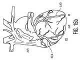
図1ないし図3は、閉塞したときに心臓に重大なダメージを起こすことになると目される冠動脈の位置を示す心臓の種々の図である。図1は、大動脈12から心臓10の右側に沿って下降する右冠動脈(RCA)を示す非常に概略的な図である。また、この大動脈から心臓の左側に沿って降りるのは、左主(LM)冠動脈であり、これは、心臓の前側(前部)にある左前下行枝(LAD)と心臓の後側(後部)の周りを包む形の左冠動脈回旋枝(LCx)とを形成するよう直ちに分岐する。3つの全ての主要な血管は、特徴的な曲がりくねった経路において心臓10の周りを最終的には包むものとなっており、新鮮な血液の心筋への一定した供給をなすようにしていることが分かる。 FIGS. 1-3 are various views of the heart showing the location of the coronary arteries that are expected to cause significant damage to the heart when occluded. FIG. 1 is a very schematic diagram showing the right coronary artery (RCA) descending from the
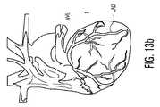
図2は、この心臓10の前方側からの同じ動脈及び枝路を、当該心臓のより解剖学的に正確な描写で示している。図3において、心臓10は、心臓の前部及び後部側両方における冠動脈の曲がりくねった経路が容易に視覚化されることができるように半透明の分枝として描かれている。 FIG. 2 shows the same artery and branch from the anterior side of the
本発明の目的は、標準又は非標準のECG検査のトレースの分析からこれら冠動脈及び枝路のどれが閉塞されているかを自動的に識別することを可能にすることである。ECGの正しい解釈は、多大な経験を必要とする。何故なら、それは色々なリードのトレーシングにおける広い範囲のパターンの熟知に絡むからである。リードの慣例的でないシステムを用いたECGは、慣例的ECGの解釈において培われた多数の経験から必然的に外れ、これにより、概して望ましくないものとみなされる場合もある。発生したトレーシングは、当該慣例的でないシステムを熟知した比較的少数の者によってのみ理解可能なものとなる。したがって、本発明は、慣例的な電極配置による標準のECG検査において実現可能であることが重要である。図4aは、10個のリード電極を持つ慣例的な12リードECG検査のために患者の胴に位置づけられたV1〜V6の6つの電極の配置を示している。各電極は、1つ以上の他の電極と組み合わせで機能し、個々の心臓筋肉細胞の消極及び再分極により生成される電圧を検出する。検出された電圧は、合成され処理されて、時間的に変化する電圧の12個のトレーシングを生成する。こうして生成されたトレーシングは、次のようになる。
ここで、背臥位の被検体の短期心電図記録をなす最も広く使用されている標準のシステムでは、上記電位、及びこれらの関連の電極位置は、次の如くである。
VL 左腕上の電極の電位
VR 右腕上の電極の電位
VF 左脚上の電極の電位
V1 胸部正面上の電極の電位(第4肋骨間空における胸骨の右)
V2 胸部正面上の電極の電位(第4肋骨間空における胸骨の左)
V4 第5肋骨間空における左鎖骨中央線における電極の電位
V3 V2とV4の電極間の電極中間部の電位
V6 第5肋骨間空における左中腋窩線における電極の電位
V5 V4とV6の電極間の電極中間部の電位
G (上に示してはいないが)電位VL,VR,VF及びV1ないしV6が相対的に測定されるところの接地又は基準電位(大抵は(必然的ではないが)、右脚上にこの接地又は基準電極が配置される)。Here, in the most widely used standard system for short-term electrocardiogram recording of a supine subject, the potentials and their associated electrode positions are as follows.
VL Potential of electrode on left arm VR Potential of electrode on right arm VF Potential of electrode on left leg V1 Potential of electrode on front of chest (right of sternum in fourth intercostal space)
V2 Potential of electrode on front of chest (left of sternum in fourth intercostal space)
V4 Potential of electrode at left midclavicular line in fifth intercostal space V3 Potential of electrode middle portion between electrodes of V2 and V4 V6 Potential of electrode at left middle axillary line in fifth intercostal space V5 Between electrodes of V4 and V6 The potential G at the middle of the electrode G (not shown above), where the potentials VL, VR, VF and V1 to V6 are relatively measured, or the ground or reference potential (usually (although not necessarily)), This ground or reference electrode is placed on the right leg).
本発明は、慣例的な12リードECGシステム及び13,14,15,16,17又は18リードシステム又はこれを上回る56リード及び128リード体表マッピングシステムとともに用いられるのに適している。3リード(EASI及びその他)、5リード及び8リードシステムも、当該技術において知られているように、精度を低くして12リードから派生するように用いることができる。例えば、米国特許第5,377,687号(Evans氏ら)及び米国特許第6,217,525号(Medema氏ら)を参照されたい。要するに、本発明の実現形態は、任意の数のリード及び電極を使うことができる。図4a及び図4bは、高度なリードシステムにより用いられる電極のうちの幾つかを示している。V7,V8及びV9の電極は、V6電極から当該胴部の周りをまとい続けることが分かる。V3R,V4R,V5R及び付加的電極は、体の右側周辺から始まり、V3,V4,V5及びその他の電極の位置を体の左側に鏡で映した形とする。 The present invention is suitable for use with conventional 12-lead ECG systems and 13, 14, 15, 16, 17 or 18 lead systems or better 56 and 128 lead body surface mapping systems. Three lead (EASI and others), five lead and eight lead systems can also be used to derive from 12 leads with reduced accuracy, as is known in the art. See, for example, US Pat. No. 5,377,687 (Evans et al.) And US Pat. No. 6,217,525 (Medema et al.). In short, implementations of the present invention can use any number of leads and electrodes. Figures 4a and 4b show some of the electrodes used by the advanced lead system. It can be seen that the V7, V8 and V9 electrodes continue to wrap around the barrel from the V6 electrode. V3R, V4R, V5R and additional electrodes start from around the right side of the body and mirror the positions of V3, V4, V5 and other electrodes on the left side of the body.
図5は、本発明を用いるのに適した診断用ECGシステムをブロック図の形で示している。複数の電極20は、患者の皮膚に付けるために設けられている。大抵は、これら電極は、皮膚に貼り付く導電性粘着ゲル表面を持つ使い捨ての導電体である。各導電体は、ECGシステムの電極線に嵌るか又は留まるスナップ又はクリップを有する。電極20は、電極により受信される信号の条件を整えるECG取込モジュール22に結合される。これら電極信号は、概して、衝撃危険性から患者を保護しまた患者が例えば除細動を受けているときにECGシステムを保護する電気的絶縁装置24により、ECG処理モジュール26に結合される。光学的絶縁は、概して電気的絶縁のために用いられる。そして、処理されたECG情報は、画像ディスプレイに表示され、又は出力装置28によりECGレポートに印刷される。 FIG. 5 illustrates in block diagram form a diagnostic ECG system suitable for use with the present invention. A plurality of electrodes 20 are provided for application to the patient's skin. Mostly, these electrodes are disposable conductors having a conductive adhesive gel surface that sticks to the skin. Each conductor has a snap or clip that fits or stays on the electrode wire of the ECG system. Electrode 20 is coupled to an
図6は、より詳細に取込モジュール22を示している。大抵は振幅がちょうど数ミリボルトの電極信号は、これも大抵は除細動パルスからの高電圧保護を有する増幅器により増幅される。これら増幅された信号は、フィルタリングにより調整され、その後にアナログ/ディジタル変換器によりディジタル式に標本化された信号に変換される。そして、これら信号は、12リードシステムのための上記のもののような組み合わせでリード信号を得るように、様々な電極信号を差動で合成することによってフォーマット化される。これらディジタルリード信号は、CPU34の制御の下でECG処理のために転送される。取込モジュールの特定の電子回路構成部の多くは、しばしば、特定用途向け集積回路(ASIC)の形態で実現される。 FIG. 6 shows the
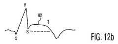
図7は、代表的な診断用ECGシステムの分析部のブロック図である。ペースパルス検出器42は、電気的スパイク及び1台装着している患者のペースメーカにより生じるその他の電気的異常性を識別し除外する。QRS検出器44は、電気的トレースの主要なパルスを検出する。図12aは、代表的な正常なECGトレースを示しており、Q−R−Sセグメントは、左心室の収縮をシミュレートするパルスである、当該トレースの主たる電気的パルスを描く。QRS合成の描写は、波形分割器46により行われる当該トレースの比較的小さい動揺を検出するための基礎を形成する。この波形分割器は、P波を含むトレースセグメント及びECGトレースのQないしUセグメントの全シーケンスを描く。ここで全部が描かれる各波形により、心拍分類器48は、新しい心拍の各々を以前の心拍と比較し、心拍を当該個人の正常(規則的)なものとして又は異常(不規則)なものとして分類する。心拍の分類によって、平均心拍分析器52は、正常心拍の特性を規定することができ、平均心拍の振幅及び部分(セグメント)持続長が54で測定される。心拍分類は、56で心調律を測定するために用いられる。図8,図9a及び図9bは、このECGトレース処理の機能的な図である。図8の左側には、リードI,II,V1,V2,V5及びV6からのECGトレースのシリーズ60がある。この心拍分類器48は、様々な心拍特性を比較し、正常なもの(N*,0)として当該心拍のうちのいくつかを分類している。例えば、リードV5及びV6からの心拍の全ては、正常なものとして分類されている。他の4つのリードは、早熟な心室収縮の特性(PVC,1)を示す心拍を含む。62では、ECGシステムは、正常な心拍の特性を集約し、異常な心拍の特性を排除し、平均的心拍を生成するように、時間的に当該各心拍を位置合わせしかつそれらの平均をとる。64でのトレースは、この例において示される6つのリードに対する平均心拍のトレースを示している。図9aにおいて、66に示される様々な特性、例えば、Q波、R波及びT波の振幅及び持続長、並びにQRSやQTのような波間間隔について測定される。これらの測定値は、この例の6つのリードに対する測定テーブル68において記録されるものとして示されている。12リードシステムのための完全な測定テーブルの例は、図9bに示される。FIG. 7 is a block diagram of an analysis unit of a typical diagnostic ECG system. The pace pulse detector 42 identifies and eliminates electrical spikes and other electrical abnormalities caused by the patient's pacemaker wearing it.
ECG波及びそれらの測定値は、患者のECG波形についてのレポートの生成のためのレポート発生パッケージを伴うオフラインワークステーションに送ることができる。但し、心電計のPhilips Pagewriter(R)ラインやPhilips TraceMaster(R)ECG管理システムのような多くの診断用ECGシステムは、オンボードECGレポーティングパッケージを有する。図10は、これらシステムにより生成可能なレポートのタイプを示している。70に示される12個のリードの波形の特性及び図9bの測定値から、臨床医は、或る特定の心臓症状を臨床的に規定する方法で様々な特性を識別し、論理的に合成し、含有させ又は排除するためのレポーティングソフトウェアをプログラムすることができる。このタイプの代表的プログラムは、図10における72に示され、74に示されるような治療担当心臓専門医のためのECGレポートをもたらすことになる。急性心筋梗塞を患っている患者にとっては、このレポートは、心臓の中の急性心筋虚血の存在と、時として、心臓の領域の或る種の領域特定及び梗塞により影響を受ける領域のサイズを、大抵は示すこととなる。但し、当該障害物を除去するためにカテーテルを手に持って待機している介入の心臓専門医には、より多くの情報が必要である。心臓専門医は、閉鎖した動脈又は枝路にカテーテルを入れ、心臓の影響受けている領域に血液潅流を戻すように、即座に取り掛かることができるようにどの主要な冠動脈及び冠状動脈のどの枝路が閉鎖されているのかが知りたい。 The ECG waves and their measurements can be sent to an offline workstation with a report generation package for generating a report on the patient's ECG waveform. However, many diagnostic ECG systems, such as the ECG Philips Pagewriter® line and the Philips TraceMaster® ECG management system, have an on-board ECG reporting package. FIG. 10 shows the types of reports that can be generated by these systems. From the waveform characteristics of the twelve leads shown at 70 and the measurements in FIG. 9b, the clinician identifies and logically synthesizes various characteristics in a manner that clinically defines a particular cardiac condition. Reporting software for inclusion or exclusion can be programmed. A representative program of this type is shown at 72 in FIG. 10 and will result in an ECG report for the treating cardiologist as shown at 74. For patients suffering from acute myocardial infarction, this report shows the presence of acute myocardial ischemia in the heart, and sometimes the identification of certain regions of the heart region and the size of the region affected by the infarction. , Usually will show. However, more information is needed for an interventional cardiologist who is waiting with a catheter in his hand to remove the obstruction. The cardiologist puts the catheter into a closed artery or branch, and which major coronary artery and which branch of the coronary artery can be immediately started to return blood perfusion to the affected area of the heart. I want to know if it is closed.
本発明の原理により、本発明者らは、ECGデータベースの統計学的分析及びこれらの種々の冠動脈の幾何学的構造との関係性を検討し、急性虚血イベントの責任動脈を識別するための自動化された技術を開発した。本発明の技術は、2つの主たる冠動脈、RC及びLMのうちの1つ、又はLMの2つの主要な枝路のうちの1つ、LDA又はLCxを、責任動脈として識別することができる。そして心臓専門医は、責任動脈の識別(情報)を、ECGレポートにおいて、スクリーン上に視覚的に、ECGトレースのディスプレイにおいて、聞こえる形で、又は他の出力手段によって、知らされる。本発明者らは、ST部分上昇を伴う場合及び伴わない場合の状況における、結果として得られるECGにおけるST偏差及び他のECG測定値(例えば、Q波、R波、T波の振幅及び持続長、並びにQRS及びQTのような波間間隔)及び急性心虚血は、種々の冠動脈においてそして動脈の種々のレベルにおいて障害が生じている場合に、種々のパターンを有することを認識した。冠状動脈は、或る特定のパターン及び偏りを有することを考えると、これらST偏差は、患者の冠動脈の幾何学的構造に密接に関連する。本発明の技術は、ST偏差及び標準のECGリード構成の他の測定値を検査することを可能にし、それらの分類は、特定の冠動脈又は枝路が急性虚血イベントの原因であるという結論を下すことを規定する。 In accordance with the principles of the present invention, we examine the statistical analysis of the ECG database and its relationship to the various coronary artery geometries to identify the arteries responsible for acute ischemic events. Developed automated technology. The technique of the present invention can identify two major coronary arteries, one of RC and LM, or one of the two major branches of LM, LDA or LCx, as the responsible artery. The cardiologist is then informed of the identification (information) of the responsible artery in the ECG report, visually on the screen, in the display of the ECG trace, in an audible manner, or by other output means. We have ST deviations and other ECG measurements in the resulting ECG in situations with and without ST segment elevation (eg Q-wave, R-wave, T-wave amplitude and duration). , And interwave intervals such as QRS and QT) and acute cardiac ischemia have been recognized to have different patterns in various coronary arteries and at various levels of arteries. Given that the coronary arteries have a certain pattern and bias, these ST deviations are closely related to the patient's coronary artery geometry. The technique of the present invention allows examination of ST deviation and other measurements of the standard ECG lead configuration, and their classification concludes that a particular coronary artery or branch is responsible for an acute ischemic event. Stipulate that
例えば、LADが閉鎖されると、心臓の前部壁への血液の流れは減ることになる。この状況において、当該前部壁に面するECGリードV2,V3,V4,V5の幾つかは、ST上昇を示すことになる。これに対応して、心臓の反対の壁部に面するECGリードは、ST低下を示すことになる。この原理を用いることによって、心臓壁部の急激に閉塞した領域に供給する責任冠動脈又は枝路を識別することができる。 For example, when the LAD is closed, blood flow to the anterior wall of the heart will be reduced. In this situation, some of the ECG leads V2, V3, V4, V5 facing the front wall will show an ST rise. Correspondingly, an ECG lead facing the opposite wall of the heart will show ST depression. By using this principle, the responsible coronary artery or branch supplying the rapidly occluded region of the heart wall can be identified.
この原理は、さらに、図11a及び図11bに示されるように、ECGリードを冠動脈の幾何学的構造に関係づけることによって理解することができる。図11a及び図11bは、図3に示されるようなRCA、LCA、LCx及びLADを伴う心臓10の前面図である。血管の経路は、vG電極と一緒に12リードシステムの6つの肢リードI,II,III,aVR,aVL及びaVFを生成するために、上に示したように組み合わせられる3つの肢電極に関係づけられる。下部リードII,III及びaVFは、当該下部又は左心室の横隔膜壁のパンデージポイントから心臓の電気的活動を見せる。横のリードI,aVL,V5(図11bにおける5として示される)及びV6(図11bにおける6として示される)は、左心室の横の壁部のパンデージポイントからの電気的活動を示す。V1及びV2リード(図11bにおいて1及び2として示される)は、胸骨(図4a参照)の両側の電極から出されるものであり、心臓の隔壁のパンデージポイントからの電気的活動を示すものである。前部リードV3及びV4は、心臓の前部壁のパンデージポイントからの電気的活動を示す。本発明は、リード信号及び心臓に対するそれらの対応するパンデージポイントを考慮に入れて、狭窄症の冠動脈を識別するようにしている。 This principle can be further understood by relating the ECG lead to the coronary artery geometry, as shown in FIGS. 11a and 11b. 11a and 11b are front views of the
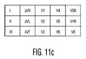
図11cは、ECGレポートに通常用いられる種々のリードに対するECGトレースの位置付けを示している。12リードレポートは、図11cにおける第1の4つの列によって示されるように3×4行列でリード信号を配列するものである。下部電極II,III及びaVFの信号は、第1及び第2列に位置づけられ、横リード信号は、第1の列(I)の上部、第2の列(aVL)の中央、及び第4の列(V5及びV6)、…に位置づけられる。本発明の実施例は、その分析を行い当該結果を臨床医に提示するよう当該リードのこの標準の方向づけを有利に用いることができる。図11cの例では、第5の列が、以下の例に示されるように高次リードに対して付加される。 FIG. 11c shows the positioning of the ECG trace for the various leads commonly used in ECG reports. The 12 lead report is an arrangement of the read signals in a 3 × 4 matrix as indicated by the first four columns in FIG. 11c. The signals of the lower electrodes II, III and aVF are positioned in the first and second columns, and the lateral lead signal is the upper part of the first column (I), the center of the second column (aVL), and the fourth Located in columns (V5 and V6),. Embodiments of the present invention can advantageously use this standard orientation of the lead to perform the analysis and present the results to the clinician. In the example of FIG. 11c, a fifth column is added for higher order leads as shown in the following example.
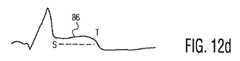
本発明の他の態様によれば、ECGリード信号は、特定の冠動脈及び枝路の狭窄症に関係する上昇及び低下ST部分の特定のパターンに対して分析される。図12aの正常なECGトレースでは、ST部分80の信号レベルは、ECGトレースの公称のベースラインにあるか又はこれに非常に近いところにある。冠動脈が全部塞がれるようになるとき、当該動脈に近接したリードのST部分82は、図12bに示されるように高く上昇することになり、当該点線は、当該トレースの公称のベースラインを示す。ST部分は、100μボルト以上上昇する可能性がある。心臓の他方の側に隣接したECGリードは、対応の下降を示すこととなり、これが検出され、ST上昇の正の識別のために当該上昇したトレースと相関づけられることができる。さらに、ST上昇の量は、時間及び狭窄症の程度の関数として変化することになる。例えば、閉塞を生じさせるイベントの時間の直後に、リードのST部分は、図12cに示されるように比較的に大きな上昇84を示すことになる。時間の経過とともに、当該上昇は低下することになり、ST上昇86は、図12dに示されるように出現することができる。時間のかなり長い期間の後、心臓はその新しい生理学的状態に適合し始める頃、又は動脈が部分的にのみ閉鎖させられるときに、ST部分は、図12eにおける88で示されるように少しだけ上昇させられることになる。したがって、胸痛の開始の時間について患者に質問することによって、当該イベントの時間を記録することができ、期待される上昇の程度を評価することができる。また、上昇の程度は、古い血餅が時間とともに固化しているものの如き部分的にのみ閉鎖した血管を認識するために用いられることができる。これらの兆候は、応急手当を必要としない血管を無視するために用いることができるとともに、介入処置は、正に重大な閉鎖を被る血管に差し向けられる。 According to another aspect of the invention, the ECG lead signal is analyzed for a particular pattern of ascending and descending ST portions associated with a particular coronary artery and branch stenosis. In the normal ECG trace of FIG. 12a, the signal level of the
図13a,図14a及び図15aは、責任冠動脈が臨床医のために識別されるとしたECGレポートの例を示している。図13aにおいて、12リードトレースは、上述した3×4パターンにおいて配列される。ここでも示されるのは、3つの付加的リード、心臓の後部側における2つ(V8及びV9)を伴う胴体の右側における2つ(V4R及びV5R)である。丸のついたリードトレースは、V3及びV4並びに隣接のリードV2及びV5の前部リードグループにおける大なるST部分上昇を示している。ST上昇はまた、横リードV6、I及びaVLにおいても確認される。リードV6、I及びaVLにおけるST上昇と同時に生じうるリードグループV2,V3,V4,V5におけるST上昇の存在は、左前下降(LAD)枝の閉鎖を示しており、この結論は、印刷され図13aのレポートの上部において強調されるように示される。 Figures 13a, 14a and 15a show examples of ECG reports where the responsible coronary artery is identified for the clinician. In FIG. 13a, the 12 lead traces are arranged in the 3 × 4 pattern described above. Also shown here are two on the right side of the torso (V4R and V5R) with three additional leads, two on the posterior side of the heart (V8 and V9). The rounded lead trace shows a large ST partial rise in the front lead group of V3 and V4 and adjacent leads V2 and V5. ST elevation is also confirmed in lateral leads V6, I and aVL. The presence of ST rise in lead groups V2, V3, V4, V5, which can occur simultaneously with ST rise in leads V6, I and aVL, indicates the closure of the left anterior descending (LAD) branch, and this conclusion is printed and shown in FIG. Shown as highlighted at the top of the report.
図13b及び図13cは、何故これら前部及び横のリードグループがLAD閉鎖を示すかを示している。図13bは、心臓の左側を示す横リードaVL及びIを示し、これにより、右冠動脈症状よりも左冠動脈症状に敏感なものとなっている。横リードグループのリードV6は、図13cに示されるのと同様に方向づけられている。図13cはまた、LADに関係した前部リードV3及びV4並びに隣接の前部リードV2及びV5を示している。これらリードは、心臓の前部表面を示しているので、LCx症状よりもLAD症状に敏感である。より高次のリードセットが12リードセットに代えて用いられる場合、ST上昇リードは、心臓の反対の壁部に向くリードにおけるST低下により鏡面反射された形となる。この例は、図13aにおいて確認され、心臓の右側を示すV4Rリードが或る程度のST低下を示している。したがって、2つの左側リードグループにおける大幅なST上昇は、責任動脈としてのLAD冠動脈を指示するものである。 Figures 13b and 13c show why these front and side lead groups indicate LAD closure. FIG. 13b shows lateral leads aVL and I showing the left side of the heart, which makes it more sensitive to left coronary artery symptoms than right coronary artery symptoms. The lead V6 of the lateral lead group is oriented as shown in FIG. 13c. FIG. 13c also shows the front leads V3 and V4 and the adjacent front leads V2 and V5 related to LAD. These leads are more sensitive to LAD symptoms than LCx symptoms because they represent the anterior surface of the heart. If a higher order lead set is used instead of a 12 lead set, the ST elevated lead will be specularly reflected due to the ST drop in the lead toward the opposite wall of the heart. This example is confirmed in FIG. 13a, where the V4R lead showing the right side of the heart shows some ST drop. Thus, a significant ST elevation in the two left lead groups is indicative of the LAD coronary artery as the responsible artery.
図14aのECGレポートは、下部リードII,III及びaVFにおけるST上昇を示している。ST上昇はまた、後部リードV8にも存在する。この後部リードのST上昇は、前部リードV1,V2及びV3においてST低下により鏡面反射された形となる。さらに、前部胸部リードV1〜V3のST低下のレベルは、下部肢リードII,III及びaVFのST上昇より大きい。測定値のこのセットは、図14aのレポートの上部においてレポートされ強調されるように、左冠動脈回旋枝(LCx)の閉鎖を示している。隣接の後部リードV7及びV9は、用いられると、リードV8のものと同様のST上昇を示すことになる。 The ECG report in FIG. 14a shows ST rise in lower leads II, III and aVF. ST rise is also present in the rear lead V8. This ST rise of the rear lead is in the form of being specularly reflected by the ST drop in the front leads V1, V2 and V3. In addition, the level of ST decline in the front chest leads V1-V3 is greater than the ST rise in the lower limb leads II, III and aVF. This set of measurements indicates closure of the left coronary artery rotator (LCx), as reported and highlighted at the top of the report of FIG. 14a. Adjacent rear leads V7 and V9, when used, will exhibit an ST rise similar to that of lead V8.
図14b及び図14cは、この兆候の解剖学的な図を提供するものである。図14bに示される下部リードII,III及びaVFは、下から心臓を見ており、これにより、左右の冠動脈の上部の症状に対して感度が低く、心臓の周囲及び下側を取り巻くので左回旋枝の閉鎖にはより感度が高いものとなっている。後部リードV7,V8及びV9は、LCxの後部箇所に対向しており、これにより、より前方にあるRCA及びLAD冠動脈よりもLCx症状に感度が高い。これら後部リードの感度は、前部リードV1,V2及びV3のST低下により鏡面反射される形となる。したがって、ST低下との整合を伴うST上昇のこのセットは、LCx冠動脈の閉鎖の兆候である。 Figures 14b and 14c provide an anatomical view of this indication. The lower leads II, III and aVF shown in FIG. 14b look at the heart from below, which is less sensitive to the symptoms of the upper part of the left and right coronary arteries and surrounds the lower and upper sides of the heart so It is more sensitive to branch closure. The posterior leads V7, V8, and V9 are facing the posterior location of LCx, which is more sensitive to LCx symptoms than the more forward RCA and LAD coronary arteries. The sensitivity of these rear leads is specularly reflected by the ST drop of the front leads V1, V2 and V3. Thus, this set of ST elevation with matching ST decline is an indication of LCx coronary artery closure.
図15aは、下部リードグループII,III及びaVFにおけるST上昇を伴うECGレポートを示している。リードIIIにおけるST上昇は、リードIIのものよりも大きい。ST上昇はまた、右の胸部リードV4R及びV5Rにおいても確認される。このセットの測定値は、ECGレポートにおいて記述され強調されているように右の冠動脈(RCA)閉鎖を示している。下部リードグループ若しくは右胸部リードグループ又はこれら双方のST上昇は、RCA閉鎖を示している。リードaVRにおけるST上昇も存在しうる。ここでも存在しうる他の兆候は、右側リードにおけるST上昇を鏡面反射した形態を採る、前部(V3,V4)及び横(I,aVL,V5)リードグループにおける潜在的ST低下を含む。ST低下のレベルは、図15aにおいて確認されるように、下部リードにおけるST上昇よりも概して低い。 FIG. 15a shows an ECG report with ST elevation in lower lead groups II, III and aVF. The ST rise in lead III is greater than that of lead II. ST elevation is also confirmed in the right chest leads V4R and V5R. This set of measurements indicates right coronary artery (RCA) closure as described and emphasized in the ECG report. An ST elevation in the lower lead group or right chest lead group or both indicates RCA closure. There may also be an ST rise in the lead aVR. Other signs that may also be present include potential ST decline in the front (V3, V4) and lateral (I, aVL, V5) lead groups, which takes the form of a specular reflection of the ST rise in the right lead. The level of ST reduction is generally lower than ST rise in the lower lead, as confirmed in FIG. 15a.
図15b及び図15cは、これら兆候の解剖学的関係を示している。下部リードII,III及びaVFは、RCA及びLADの双方が血液を供給するところの心臓の底部における症状に敏感であるが、IIIリードは、左側のLADに近いIIリードよりも、右側RCAにより近接している。図15cに示されるものを含む右胸部リードも、右側の症状に対する感度がより高い。また、aVRリードは、右心室の領域における症状に敏感であり、これにより、右側にも感度が高い。このST上昇を鏡面反射する形のST低下は、心臓の左側に関連した前部及び横リードにおいて期待される。したがって、このセットの兆候は、RCAを責任冠動脈と識別することになることが分かる。 Figures 15b and 15c show the anatomical relationship of these signs. Lower leads II, III and aVF are sensitive to symptoms at the bottom of the heart where both RCA and LAD supply blood, but the III lead is closer to the right RCA than the II lead close to the left LAD is doing. The right chest lead, including that shown in FIG. 15c, is also more sensitive to the right symptom. The aVR lead is also sensitive to symptoms in the region of the right ventricle, which is also sensitive to the right side. This ST elevation in the form of a specular reflection of the ST elevation is expected in the anterior and lateral leads associated with the left side of the heart. Thus, it can be seen that this set of signs will identify the RCA as the responsible coronary artery.
左主(LM)冠動脈の閉鎖は、その上部位置が心臓の上部にあるものであり、同様に示すことができる。図16のECGレポートを参照すると、LM閉鎖は、心臓の上方室(右心室)に関連づけられているaVRリードにおけるST上昇により示される。これは、時として、リードV1におけるST上昇と同時に起こるものであるが、この場合、V1リードはST低下を示す。他のリードに示される程度の異常なSTレベルは、殆どのリードにおいてST低下を示すことになる。この場合、当該他のリードの全ての丸付きのトレースは、心臓の右側におけるリードaVRに隣接していることによりリードV4R以外はST低下を示す。V4Rリードの少しのST上昇は、心臓の他方の側のリードにおいて確認されるST低下を鏡面反射した形をとる。このセットの測定値は、LMが責任冠動脈であることを示す。LM閉鎖において確認される代表的な拡散ST低下は、急性虚血イベントとして通常認識されるものではなく、他の急性虚血イベントと同じか又はそれよりも悪い意味を有するものである。 The closure of the left main (LM) coronary artery is one whose upper position is at the top of the heart and can be shown as well. Referring to the ECG report of FIG. 16, LM closure is indicated by ST elevation in the aVR lead associated with the upper ventricle (right ventricle) of the heart. This sometimes occurs simultaneously with the ST rise in lead V1, but in this case, the V1 lead shows a ST fall. An abnormal ST level to the extent shown on other leads will show ST degradation on most leads. In this case, all rounded traces of the other leads show ST reduction except for lead V4R due to being adjacent to lead aVR on the right side of the heart. A slight ST rise in the V4R lead takes the form of a specular reflection of the ST drop observed in the lead on the other side of the heart. This set of measurements indicates that the LM is the responsible coronary artery. The typical diffuse ST decline observed in LM closure is not normally recognized as an acute ischemic event, but has the same or worse meaning than other acute ischemic events.
患者が心臓発作の症状を伴うもののECG測定値がリードにおける有意なST上昇を呈しないとき、リードは、上記ST低下の例のいずれかのために上昇させられるべきできる。ST上昇の無い特定の閉鎖の特徴を示しているST低下兆候の存在は、被検体の冠動脈の部分的閉鎖又は切迫した完全な閉鎖を示し、医師により見つけられる他の兆候とともに検討するために治療担当介入心臓専門医に示されるべきである。 When the patient has a heart attack symptom but the ECG measurement does not exhibit a significant ST elevation in the lead, the lead should be elevated for any of the above examples of ST depression. The presence of ST-lowering signs, which are characteristic of specific closure without ST elevation, indicates a partial or imminent complete closure of the subject's coronary artery and is treated to be examined along with other signs found by the physician Should be shown to the attending cardiologist.
上述したST上昇及び低下特性に加えて、Q波、R波、T波の振幅及び持続長及びQRS及びQTのような波間間隔などの他のECG測定値も、責任冠動脈の識別において適用可能なものとして用いることができる。13〜18リードECGシステム及び64及び128リードECG体表マップを含む高次のリードセットの使用は、責任冠動脈識別の精度を高めるために付加的な追加情報を提供することができる。12リードよりも少ないシステムの場合、恐らくは低下する精度で本発明の技術を実現するために、付加的なリード信号を導くことができる。 In addition to the ST rise and fall characteristics described above, other ECG measurements such as Q-wave, R-wave, T-wave amplitude and duration and inter-wave spacings such as QRS and QT are also applicable in identifying the responsible coronary artery. It can be used as a thing. The use of a 13-18 lead ECG system and a higher order lead set including 64 and 128 lead ECG body surface maps can provide additional additional information to increase the accuracy of responsible coronary artery identification. For systems with fewer than 12 leads, additional lead signals can be derived to implement the technique of the present invention, possibly with reduced accuracy.
Claims (24)
Translated fromJapanese当該心臓に関係した種々のバンテージポイントから当該心臓の電気的活動を取得するように適合された1組の電極と、
前記電極に結合され、増強された電極信号を生成するよう動作するECG取込モジュールと、
前記電極信号に応答して、種々のバンテージポイントから当該心臓の電気的活動を測定する複数のリードトレースの生成をなすために電極信号を合成するように動作するECGプロセッサであって、リードトレースにおけるST上昇を検出し、冠動脈又は枝路の閉鎖を示すST上昇パターンを識別するプロセッサと、
急性虚血イベントに関連した責任冠動脈又は枝路を識別する出力装置と、
を有するシステム。A diagnostic ECG system for identifying a responsible coronary artery associated with acute myocardial infarction, comprising:
A set of electrodes adapted to obtain electrical activity of the heart from various vantage points associated with the heart;
An ECG capture module coupled to the electrode and operative to generate an enhanced electrode signal;
An ECG processor that operates to synthesize electrode signals to generate a plurality of lead traces that measure electrical activity of the heart from various vantage points in response to the electrode signals, A processor that detects ST elevation and identifies an ST elevation pattern indicative of coronary artery or branch closure;
An output device for identifying a responsible coronary artery or branch associated with an acute ischemic event;
Having a system.
前記ECGプロセッサはさらに、LAD冠動脈の閉鎖を示唆するものとして前記横リードグループにおけるST上昇と同時に起きうる前記前部リードグループにおけるST上昇を識別し、
前記出力装置は、当該示唆に応答して責任冠動脈としてLAD冠動脈を識別する、
システム。2. The diagnostic ECG system of claim 1, wherein the ECG processor is responsive to the electrode signal and includes a front lead group and leads including one or more of leads V2, V3, V4, V5. Generating a signal of a horizontal lead group including one or more of V6, I, and aVL;
The ECG processor further identifies ST elevation in the anterior lead group that may occur concurrently with ST elevation in the lateral lead group as an indication of LAD coronary artery closure;
The output device identifies the LAD coronary artery as a responsible coronary artery in response to the suggestion;
system.
前記ECGプロセッサは、さらに前記前部リードグループにおけるST低下を識別し、
前記ECGプロセッサは、さらに、前記下部リードグループ及び前記後部リードグループにおけるST上昇、及び前部リードグループにおけるST低下を、当該LCx冠動脈の閉鎖を示唆するものとして識別し、
前記出力装置は、当該示唆に応答して、前記LCx冠動脈を責任冠動脈として識別する、
システム。2. The diagnostic ECG system of claim 1, wherein the ECG processor is responsive to the electrode signal to provide a lower lead group including one or more of leads II, III, aVF, leads V7, V8. , V9, generating a signal for a rear lead group including one or more of V9 and a front lead group including one or more of leads V1, V2, V3,
The ECG processor further identifies ST degradation in the front lead group;
The ECG processor further identifies ST elevation in the lower lead group and the posterior lead group and ST decline in the anterior lead group as indicative of closure of the LCx coronary artery;
In response to the suggestion, the output device identifies the LCx coronary artery as a responsible coronary artery.
system.
前記ECGプロセッサは、さらに、リードaVRにおけるST上昇と同時に起きうる前記下部リードグループ及び/又は右胸部リードにおけるST上昇を、右冠動脈(RCA)の閉鎖を示唆するものとして識別し、
前記出力装置は、当該示唆に応答して、前記RCAを責任冠動脈として識別する、
システム。2. The diagnostic ECG system of claim 1, wherein the ECG processor is responsive to the electrode signal to one or more of leads II, III, aVF, one of leads V3R-V5R. Or a plurality of right chest lead and lead aVR signal generation,
The ECG processor further identifies ST elevation in the lower lead group and / or right chest lead that may occur simultaneously with ST elevation in lead aVR as indicative of right coronary artery (RCA) closure;
In response to the suggestion, the output device identifies the RCA as a responsible coronary artery.
system.
当該リードIIIにおけるST上昇は、リードIIのものよりも大きい、
システム。5. The diagnostic ECG system of claim 4, wherein both leads II and III exhibit ST elevation,
The ST rise in lead III is greater than that of lead II,
system.
前記ECGプロセッサは、さらに前記前部リードグループにおけるST低下を識別し、
前記前部リードグループにおけるST低下のレベルは、前記下部リードグループにおけるST上昇よりも小さい、
システム。6. The diagnostic ECG system of claim 5, wherein the ECG processor is further responsive to the electrode signal for a front lead group signal including one or more of leads V1, V2, V3. Generation of
The ECG processor further identifies ST degradation in the front lead group;
The level of ST decrease in the front lead group is smaller than ST increase in the lower lead group.
system.
前記ECGプロセッサは、さらに前記他のリードのうちの大部分におけるST低下を識別し、
前記ECGプロセッサは、さらに、リードV1におけるST上昇と同時に起こりうるリードaVRにおけるST上昇を、当該左主(LM)冠動脈の閉鎖を示唆するものとして識別し、
前記出力装置は、当該示唆に応答して、前記LM冠動脈を責任冠動脈として識別する、
システム。The diagnostic ECG system according to claim 1, wherein the ECG processor generates a signal of a lead aVR and a signal of a plurality of other leads including a lead V1 in response to the electrode signal;
The ECG processor further identifies ST degradation in a majority of the other leads;
The ECG processor further identifies an ST rise in the lead aVR that may coincide with an ST rise in lead V1 as an indication of closure of the left main (LM) coronary artery;
In response to the suggestion, the output device identifies the LM coronary artery as a responsible coronary artery.
system.
前記ECGプロセッサはさらに、前記リードトレースのうちの1つ又は複数におけるST低下を識別し、
前記ECGプロセッサは、さらに、リードV1,V2,V3のうちの1つ又は複数を含む前部リードのうちの1つ又は複数におけるST低下の検出に応答して、前記左冠動脈回旋枝(LCx)を部分的に閉塞した責任冠動脈として識別する、
システム。The diagnostic ECG system of claim 1, wherein the ECG processor detects a state without significant ST elevation in response to the lead trace;
The ECG processor further identifies ST degradation in one or more of the lead traces;
The ECG processor is further responsive to detection of ST depression in one or more of the anterior leads including one or more of leads V1, V2, and V3. Identify the partially occluded responsible coronary artery,
system.
前記ECGプロセッサは、さらに前記リードトレースのうちの1つ又は複数におけるST低下を識別し、
前記ECGプロセッサはさらに、リードV1,V2,V3のうちの1つ又は複数を含む前部リードのうちの1つ又は複数、及び横リードI,aVL,V5,V6のうちの1つ又は複数におけるST低下の検出に応答して、当該右冠動脈(RCA)を部分的に閉塞した責任冠動脈として識別するようにしている、
システム。The diagnostic ECG system of claim 1, wherein the ECG processor detects a state without significant ST elevation in response to the lead trace;
The ECG processor further identifies ST degradation in one or more of the lead traces;
The ECG processor further includes one or more of the front leads including one or more of the leads V1, V2, V3 and one or more of the lateral leads I, aVL, V5, V6. In response to detecting ST depression, the right coronary artery (RCA) is identified as the responsible coronary artery partially occluded.
system.
前記ECGプロセッサは、さらに当該複数の他のリードトレースにおけるST低下を識別し、
前記ECGプロセッサはさらに、前記複数の他のリードトレースにおけるST低下の検出に応答して、当該左主(LM)冠動脈を部分的に閉塞した責任冠動脈として識別する、
システム。The diagnostic ECG system of claim 1, wherein the ECG processor detects a state without significant ST elevation in the lead aVR in response to the lead trace;
The ECG processor further identifies ST degradation in the plurality of other lead traces;
The ECG processor further identifies the left main (LM) coronary artery as a responsible coronary artery that is partially occluded in response to detecting ST depression in the other lead traces.
system.
当該nリードのトレースを受けること、
ST上昇のために前記トレースを分析すること、
特定の冠動脈又は枝路の閉鎖の示唆のためのST上昇のパターンを分析すること、及び
ユーザに対して特定の冠動脈又は枝路を責任冠動脈として識別すること、
を有する方法。A method for identifying a responsible coronary artery associated with an ischemic event by an n-lead ECG system comprising:
Receiving the n-lead trace,
Analyzing the trace for ST elevation;
Analyzing the pattern of ST elevation for an indication of closure of a particular coronary artery or branch, and identifying the particular coronary artery or branch as the responsible coronary artery to the user;
Having a method.
におけるST上昇と同時に起こりうるリードV2,V3,V4,V5のうちの1つ又は複数を含む前部リードグループにおけるST上昇を、左前下降(LAD)枝の閉鎖を示唆するものとして識別することを有し、
当該識別はさらに、前記LAD冠動脈を責任冠動脈として識別することを有する、
方法。12. The method of claim 11, wherein analyzing the pattern of ST rise further includes leads that can coincide with ST rise in a lateral lead group that includes one or more of leads V6, I, aVL. Identifying ST elevation in a front lead group comprising one or more of V2, V3, V4, V5 as indicative of closure of a left anterior descending (LAD) branch;
The identification further comprises identifying the LAD coronary artery as a responsible coronary artery;
Method.
リードII,III,aVFのうちの1つ又は複数を含む下部リードグループ、及びリードV7,V8,V9のうちの1つ又は複数を含む後部リードグループのST上昇を識別すること、及び
ST低下についてリードV1,V2,V3のうちの1つ又は複数を含む前部リードグループのトレースを分析し前記リードグループにおけるST低下を識別すること、
を有し、当該識別することはさらに、当該左冠動脈回旋(LCx)枝を責任冠動脈として識別することを有する、
方法。12. The method of claim 11, wherein analyzing the ST rise pattern further comprises:
Identifying an ST rise in a lower lead group containing one or more of leads II, III, aVF and a rear lead group containing one or more of leads V7, V8, V9, and ST reduction Analyzing the trace of the front lead group including one or more of leads V1, V2, V3 and identifying ST degradation in said lead group;
And the identifying further comprises identifying the left coronary artery rotation (LCx) branch as the responsible coronary artery,
Method.
当該識別することは、さらに、当該右冠動脈(RCA)を責任冠動脈として識別することを有する、
方法。12. The method of claim 11, wherein analyzing the pattern of ST elevation further comprises lower lead groups including one or more of leads II, III, and aVF and / or leads V3R-V5R. Identifying the ST elevation of the right chest lead comprising one or more of the, wherein the level of ST elevation in lead III is greater than the level of ST elevation in lead II;
The identifying further comprises identifying the right coronary artery (RCA) as a responsible coronary artery;
Method.
当該方法はさらに、複数の他のリードにおけるST低下を識別することを有し、
当該識別することは、さらに、左主(LM)冠動脈を責任冠動脈として識別することを有する、
方法。12. The method of claim 11, wherein analyzing the ST rise pattern further comprises identifying ST rise in lead aVR;
The method further comprises identifying ST degradation in a plurality of other leads;
The identifying further comprises identifying the left main (LM) coronary artery as the responsible coronary artery;
Method.
当該nリードのトレースを受けること、
ST上昇及びST低下について前記トレースを分析すること、
有意のST上昇を持つトレースの無い状態を見つけること、
特定の冠動脈又は枝路の閉塞の兆候について前記ST低下のパターンを分析すること、及び
ユーザに対し特定の冠動脈又は枝路を部分的に閉鎖した責任冠動脈として識別すること、
を有する方法。A method for identifying a responsible coronary artery associated with an ischemic event by an n-lead ECG system comprising:
Receiving the n-lead trace,
Analyzing the trace for ST elevation and ST decline;
Finding a trace-free state with a significant ST rise;
Analyzing the ST decline pattern for signs of blockage of a particular coronary artery or branch, and identifying to the user as a responsible coronary artery that partially closed a particular coronary artery or branch;
Having a method.
当該心臓に関係している種々のバンテージポイントから当該心臓の電気的活動の取り込みをなすように適合させられた1組の電極と、
前記電極に結合され、増強された電極信号を生成するように動作するECG取込モジュールと、
前記電極信号に応答して、種々のバンテージポイントから当該心臓の電気的活動を測定する複数のリードトレースの生成をなすために電極信号を合成するよう動作するECGプロセッサであって、リードトレースにおけるST低下を検出し、左主冠動脈閉鎖を示唆する拡大したST低下を識別するECGプロセッサと、
急性虚血イベントに関連した責任冠動脈又は枝路を識別する出力装置と、
を有するシステム。A diagnostic ECG system for identifying a responsible coronary artery associated with acute myocardial infarction, comprising:
A set of electrodes adapted to capture the electrical activity of the heart from various vantage points associated with the heart;
An ECG capture module coupled to the electrode and operative to generate an enhanced electrode signal;
In response to the electrode signal, an ECG processor that operates to synthesize the electrode signal to generate a plurality of lead traces measuring the electrical activity of the heart from various vantage points, the STG in the lead trace An ECG processor that detects a decrease and identifies an expanded ST decrease indicative of a left main coronary artery closure;
An output device for identifying a responsible coronary artery or branch associated with an acute ischemic event;
Having a system.
Applications Claiming Priority (3)
| Application Number | Priority Date | Filing Date | Title |
|---|---|---|---|
| US95436707P | 2007-08-07 | 2007-08-07 | |
| US60/954,367 | 2007-08-07 | ||
| PCT/IB2008/053114WO2009019649A1 (en) | 2007-08-07 | 2008-08-04 | Automated identification of culprit coronary artery |
Publications (3)
| Publication Number | Publication Date |
|---|---|
| JP2010535570Atrue JP2010535570A (en) | 2010-11-25 |
| JP2010535570A5 JP2010535570A5 (en) | 2011-09-22 |
| JP5539199B2 JP5539199B2 (en) | 2014-07-02 |
Family
ID=40076540
Family Applications (1)
| Application Number | Title | Priority Date | Filing Date |
|---|---|---|---|
| JP2010519556AActiveJP5539199B2 (en) | 2007-08-07 | 2008-08-04 | Automatic identification of the responsible coronary artery |
Country Status (5)
| Country | Link |
|---|---|
| US (1) | US8233971B2 (en) |
| EP (1) | EP2175775A1 (en) |
| JP (1) | JP5539199B2 (en) |
| CN (1) | CN101795622B (en) |
| WO (1) | WO2009019649A1 (en) |
Cited By (1)
| Publication number | Priority date | Publication date | Assignee | Title |
|---|---|---|---|---|
| JP2014503251A (en)* | 2010-12-01 | 2014-02-13 | コーニンクレッカ フィリップス エヌ ヴェ | Automatic identification of occlusion position in the responsible coronary artery |
Families Citing this family (16)
| Publication number | Priority date | Publication date | Assignee | Title |
|---|---|---|---|---|
| CN101902959B (en)* | 2007-12-18 | 2013-11-20 | 皇家飞利浦电子股份有限公司 | Automated identification of culprit coronary artery using anatomically oriented ECG data display |
| US9510755B2 (en) | 2008-03-10 | 2016-12-06 | Koninklijke Philips N.V. | ECG monitoring sytstem with docking station |
| US8290573B2 (en)* | 2008-08-21 | 2012-10-16 | Mr Holdings (Hk) Limited | Systems and methods for quantifying and providing indicia of ST-segment resolution in an ECG signal |
| US7925337B2 (en)* | 2009-02-17 | 2011-04-12 | Mindray Ds Usa, Inc. | Systems and methods for graphic display of ST-segment deviation |
| JP2013517083A (en)* | 2010-01-20 | 2013-05-16 | コーニンクレッカ フィリップス エレクトロニクス エヌ ヴィ | Identification of the causal coronary artery using anatomically oriented ECG data from the expanded lead set |
| JP5950902B2 (en) | 2010-03-31 | 2016-07-13 | コーニンクレッカ フィリップス エヌ ヴェKoninklijke Philips N.V. | Apparatus and method for automatically determining a part of anatomy, image processing system, and computer program |
| US8838218B2 (en)* | 2010-12-28 | 2014-09-16 | Mohammad Khair | Leadless wireless ECG measurement system for measuring of bio-potential electrical activity of the heart |
| US9241677B2 (en)* | 2013-07-02 | 2016-01-26 | MobHealth Corporation | Device and methods for assessing, diagnosing, and/or monitoring heart health |
| US9167981B2 (en) | 2013-10-08 | 2015-10-27 | Mediatek Inc. | ECG device, ECG lead signal generating circuit, and related method |
| WO2016138022A1 (en) | 2015-02-25 | 2016-09-01 | Washington University | Breakaway connector |
| MX2017013027A (en)* | 2015-04-14 | 2017-12-08 | Koninklijke Philips Nv | Method and system for ecg based cardiac ischemia detection. |
| US10470701B2 (en)* | 2015-09-30 | 2019-11-12 | General Electric Company | Monitoring systems and methods for monitoring a condition of a patient |
| US10357362B2 (en)* | 2015-12-09 | 2019-07-23 | Medtronic Vascular, Inc. | Valve delivery device with a piezochromatic feedback indicator and methods of use |
| WO2021061705A1 (en)* | 2019-09-24 | 2021-04-01 | Battelle Memorial Institute | Therapeutic window for treatment of ischemia by vagus nerve stimulation |
| TWI802888B (en)* | 2021-05-27 | 2023-05-21 | 財團法人祺華教育基金會 | Cardiovascular Function Assessment System |
| WO2025027596A2 (en)* | 2023-08-01 | 2025-02-06 | Acculine Ltd. | Multi-stream biological signal processing |
Citations (1)
| Publication number | Priority date | Publication date | Assignee | Title |
|---|---|---|---|---|
| JP2007510493A (en)* | 2003-11-12 | 2007-04-26 | コンサルト イン メディスン ベスローテン フェンノートシャップ | Method and apparatus for determining the presence of an ischemic region of a human or animal heart |
Family Cites Families (3)
| Publication number | Priority date | Publication date | Assignee | Title |
|---|---|---|---|---|
| US6217525B1 (en)* | 1998-04-30 | 2001-04-17 | Medtronic Physio-Control Manufacturing Corp. | Reduced lead set device and method for detecting acute cardiac ischemic conditions |
| US6454697B1 (en)* | 2000-07-18 | 2002-09-24 | Dai-Yuan Wang | Cardiac support device and method |
| US10517883B2 (en)* | 2003-06-27 | 2019-12-31 | Zuli Holdings Ltd. | Method of treating acute myocardial infarction |
- 2008
- 2008-08-04USUS12/672,298patent/US8233971B2/enactiveActive
- 2008-08-04WOPCT/IB2008/053114patent/WO2009019649A1/enactiveApplication Filing
- 2008-08-04EPEP08789539Apatent/EP2175775A1/ennot_activeWithdrawn
- 2008-08-04CNCN2008801019953Apatent/CN101795622B/enactiveActive
- 2008-08-04JPJP2010519556Apatent/JP5539199B2/enactiveActive
Patent Citations (1)
| Publication number | Priority date | Publication date | Assignee | Title |
|---|---|---|---|---|
| JP2007510493A (en)* | 2003-11-12 | 2007-04-26 | コンサルト イン メディスン ベスローテン フェンノートシャップ | Method and apparatus for determining the presence of an ischemic region of a human or animal heart |
Cited By (1)
| Publication number | Priority date | Publication date | Assignee | Title |
|---|---|---|---|---|
| JP2014503251A (en)* | 2010-12-01 | 2014-02-13 | コーニンクレッカ フィリップス エヌ ヴェ | Automatic identification of occlusion position in the responsible coronary artery |
Also Published As
| Publication number | Publication date |
|---|---|
| CN101795622B (en) | 2012-03-21 |
| US8233971B2 (en) | 2012-07-31 |
| EP2175775A1 (en) | 2010-04-21 |
| JP5539199B2 (en) | 2014-07-02 |
| US20120010515A1 (en) | 2012-01-12 |
| CN101795622A (en) | 2010-08-04 |
| WO2009019649A1 (en) | 2009-02-12 |
Similar Documents
| Publication | Publication Date | Title |
|---|---|---|
| JP5539199B2 (en) | Automatic identification of the responsible coronary artery | |
| JP5667448B2 (en) | Automatic identification of suspect coronary arteries using anatomically oriented ECG data display | |
| US5419337A (en) | Non-invasive multi-electrocardiographic apparatus and method of assessing acute ischaemic damage | |
| US8862211B2 (en) | Apparatus and method for identifying myocardial ischemia using analysis of high frequency QRS potentials | |
| EP2190350B1 (en) | Qt interval monitoring system with alarms and trending | |
| JP6251035B2 (en) | Operating method of n-lead ECG system | |
| US20120323133A1 (en) | Identification of culprit coronary artery using anatomically oriented ecg data from extended lead set | |
| CN107530020B (en) | Method and system for ECG-based cardiac ischemia detection | |
| Murgatroyd | Handbook of cardiac electrophysiology: a practical guide to invasive EP studies and catheter ablation | |
| US20240138744A1 (en) | Apparatus and method for analysis and monitoring of high frequency electrograms and electrocardiograms in various physiological conditions | |
| van der Schaaf et al. | CineECG for visualization of changes in ventricular electrical activity during ischemia | |
| Pieper et al. | Design and implementation of a new computerized system for intraoperative cardiac mapping | |
| US11191473B1 (en) | Generation of vital sign monitoring | |
| Garvey | ST Segment Trend Monitoring of Acute Chest Pain Patients | |
| Kossick et al. | PhD" Linda Hill, DNP"(" DNS, Union University, Jackson, TN, USA:" University of Alabama at Birmingham, Birmingham, AL, USA;“University | |
| Hakacova et al. | Simulation of the QRS complex using papillary muscles positions as the site of early activation: first QRS simulation in human subjects | |
| Mirmoghisi | Electrocardiographic Monitoring During Acute Myocardial Ischemia |
Legal Events
| Date | Code | Title | Description |
|---|---|---|---|
| A521 | Request for written amendment filed | Free format text:JAPANESE INTERMEDIATE CODE: A523 Effective date:20110803 | |
| A621 | Written request for application examination | Free format text:JAPANESE INTERMEDIATE CODE: A621 Effective date:20110803 | |
| A131 | Notification of reasons for refusal | Free format text:JAPANESE INTERMEDIATE CODE: A131 Effective date:20130228 | |
| A601 | Written request for extension of time | Free format text:JAPANESE INTERMEDIATE CODE: A601 Effective date:20130530 | |
| A602 | Written permission of extension of time | Free format text:JAPANESE INTERMEDIATE CODE: A602 Effective date:20130606 | |
| A521 | Request for written amendment filed | Free format text:JAPANESE INTERMEDIATE CODE: A523 Effective date:20130828 | |
| A131 | Notification of reasons for refusal | Free format text:JAPANESE INTERMEDIATE CODE: A131 Effective date:20130919 | |
| A601 | Written request for extension of time | Free format text:JAPANESE INTERMEDIATE CODE: A601 Effective date:20131218 | |
| A602 | Written permission of extension of time | Free format text:JAPANESE INTERMEDIATE CODE: A602 Effective date:20131226 | |
| A521 | Request for written amendment filed | Free format text:JAPANESE INTERMEDIATE CODE: A523 Effective date:20140310 | |
| TRDD | Decision of grant or rejection written | ||
| A01 | Written decision to grant a patent or to grant a registration (utility model) | Free format text:JAPANESE INTERMEDIATE CODE: A01 Effective date:20140401 | |
| R150 | Certificate of patent or registration of utility model | Ref document number:5539199 Country of ref document:JP Free format text:JAPANESE INTERMEDIATE CODE: R150 | |
| A61 | First payment of annual fees (during grant procedure) | Free format text:JAPANESE INTERMEDIATE CODE: A61 Effective date:20140430 | |
| R250 | Receipt of annual fees | Free format text:JAPANESE INTERMEDIATE CODE: R250 | |
| R250 | Receipt of annual fees | Free format text:JAPANESE INTERMEDIATE CODE: R250 | |
| R250 | Receipt of annual fees | Free format text:JAPANESE INTERMEDIATE CODE: R250 | |
| R250 | Receipt of annual fees | Free format text:JAPANESE INTERMEDIATE CODE: R250 | |
| R250 | Receipt of annual fees | Free format text:JAPANESE INTERMEDIATE CODE: R250 | |
| R250 | Receipt of annual fees | Free format text:JAPANESE INTERMEDIATE CODE: R250 | |
| R250 | Receipt of annual fees | Free format text:JAPANESE INTERMEDIATE CODE: R250 | |
| R250 | Receipt of annual fees | Free format text:JAPANESE INTERMEDIATE CODE: R250 | |
| R250 | Receipt of annual fees | Free format text:JAPANESE INTERMEDIATE CODE: R250 |