JP2010533524A - Insertion device with pivoting action - Google Patents
Insertion device with pivoting actionDownload PDFInfo
- Publication number
- JP2010533524A JP2010533524AJP2010516450AJP2010516450AJP2010533524AJP 2010533524 AJP2010533524 AJP 2010533524AJP 2010516450 AJP2010516450 AJP 2010516450AJP 2010516450 AJP2010516450 AJP 2010516450AJP 2010533524 AJP2010533524 AJP 2010533524A
- Authority
- JP
- Japan
- Prior art keywords
- inserter device
- pivot
- inserter
- shaft
- guide slot
- Prior art date
- Legal status (The legal status is an assumption and is not a legal conclusion. Google has not performed a legal analysis and makes no representation as to the accuracy of the status listed.)
- Abandoned
Links
- 238000003780insertionMethods0.000titleclaimsabstractdescription144
- 230000037431insertionEffects0.000titleclaimsabstractdescription144
- 238000007920subcutaneous administrationMethods0.000claimsabstractdescription7
- 238000007918intramuscular administrationMethods0.000claimsabstractdescription4
- 230000000149penetrating effectEffects0.000claimsdescription20
- 230000003993interactionEffects0.000claimsdescription11
- 101100072702Drosophila melanogaster defl geneProteins0.000claimsdescription7
- 238000001802infusionMethods0.000claimsdescription7
- 239000012530fluidSubstances0.000claimsdescription2
- 238000007789sealingMethods0.000description5
- 239000000853adhesiveSubstances0.000description4
- 230000001070adhesive effectEffects0.000description4
- 238000011109contaminationMethods0.000description4
- 239000000356contaminantSubstances0.000description3
- 239000011888foilSubstances0.000description3
- 208000015181infectious diseaseDiseases0.000description3
- NOESYZHRGYRDHS-UHFFFAOYSA-NinsulinChemical compoundN1C(=O)C(NC(=O)C(CCC(N)=O)NC(=O)C(CCC(O)=O)NC(=O)C(C(C)C)NC(=O)C(NC(=O)CN)C(C)CC)CSSCC(C(NC(CO)C(=O)NC(CC(C)C)C(=O)NC(CC=2C=CC(O)=CC=2)C(=O)NC(CCC(N)=O)C(=O)NC(CC(C)C)C(=O)NC(CCC(O)=O)C(=O)NC(CC(N)=O)C(=O)NC(CC=2C=CC(O)=CC=2)C(=O)NC(CSSCC(NC(=O)C(C(C)C)NC(=O)C(CC(C)C)NC(=O)C(CC=2C=CC(O)=CC=2)NC(=O)C(CC(C)C)NC(=O)C(C)NC(=O)C(CCC(O)=O)NC(=O)C(C(C)C)NC(=O)C(CC(C)C)NC(=O)C(CC=2NC=NC=2)NC(=O)C(CO)NC(=O)CNC2=O)C(=O)NCC(=O)NC(CCC(O)=O)C(=O)NC(CCCNC(N)=N)C(=O)NCC(=O)NC(CC=3C=CC=CC=3)C(=O)NC(CC=3C=CC=CC=3)C(=O)NC(CC=3C=CC(O)=CC=3)C(=O)NC(C(C)O)C(=O)N3C(CCC3)C(=O)NC(CCCCN)C(=O)NC(C)C(O)=O)C(=O)NC(CC(N)=O)C(O)=O)=O)NC(=O)C(C(C)CC)NC(=O)C(CO)NC(=O)C(C(C)O)NC(=O)C1CSSCC2NC(=O)C(CC(C)C)NC(=O)C(NC(=O)C(CCC(N)=O)NC(=O)C(CC(N)=O)NC(=O)C(NC(=O)C(N)CC=1C=CC=CC=1)C(C)C)CC1=CN=CN1NOESYZHRGYRDHS-UHFFFAOYSA-N0.000description2
- 238000000034methodMethods0.000description2
- 238000004659sterilization and disinfectionMethods0.000description2
- 208000032484Accidental exposure to productDiseases0.000description1
- 241000894006BacteriaSpecies0.000description1
- 241000233866FungiSpecies0.000description1
- 102000004877InsulinHuman genes0.000description1
- 108090001061InsulinProteins0.000description1
- 102000029797PrionHuman genes0.000description1
- 108091000054PrionProteins0.000description1
- 240000004808Saccharomyces cerevisiaeSpecies0.000description1
- 241000700605VirusesSpecies0.000description1
- 231100000818accidental exposureToxicity0.000description1
- 239000000443aerosolSubstances0.000description1
- 230000036760body temperatureEffects0.000description1
- 206010012601diabetes mellitusDiseases0.000description1
- 230000036512infertilityEffects0.000description1
- 239000004615ingredientSubstances0.000description1
- 238000002347injectionMethods0.000description1
- 239000007924injectionSubstances0.000description1
- 229940125396insulinDrugs0.000description1
- 238000004519manufacturing processMethods0.000description1
- 239000000463materialSubstances0.000description1
- 210000003205muscleAnatomy0.000description1
- 238000003825pressingMethods0.000description1
- 238000007391self-medicationMethods0.000description1
- 230000001954sterilising effectEffects0.000description1
- 238000003860storageMethods0.000description1
- 230000001225therapeutic effectEffects0.000description1
- 238000002560therapeutic procedureMethods0.000description1
Images


Classifications
- A—HUMAN NECESSITIES
- A61—MEDICAL OR VETERINARY SCIENCE; HYGIENE
- A61M—DEVICES FOR INTRODUCING MEDIA INTO, OR ONTO, THE BODY; DEVICES FOR TRANSDUCING BODY MEDIA OR FOR TAKING MEDIA FROM THE BODY; DEVICES FOR PRODUCING OR ENDING SLEEP OR STUPOR
- A61M5/00—Devices for bringing media into the body in a subcutaneous, intra-vascular or intramuscular way; Accessories therefor, e.g. filling or cleaning devices, arm-rests
- A61M5/14—Infusion devices, e.g. infusing by gravity; Blood infusion; Accessories therefor
- A61M5/158—Needles for infusions; Accessories therefor, e.g. for inserting infusion needles, or for holding them on the body
- A—HUMAN NECESSITIES
- A61—MEDICAL OR VETERINARY SCIENCE; HYGIENE
- A61M—DEVICES FOR INTRODUCING MEDIA INTO, OR ONTO, THE BODY; DEVICES FOR TRANSDUCING BODY MEDIA OR FOR TAKING MEDIA FROM THE BODY; DEVICES FOR PRODUCING OR ENDING SLEEP OR STUPOR
- A61M25/00—Catheters; Hollow probes
- A61M25/01—Introducing, guiding, advancing, emplacing or holding catheters
- A61M25/06—Body-piercing guide needles or the like
- A61M25/0612—Devices for protecting the needle; Devices to help insertion of the needle, e.g. wings or holders
- A—HUMAN NECESSITIES
- A61—MEDICAL OR VETERINARY SCIENCE; HYGIENE
- A61M—DEVICES FOR INTRODUCING MEDIA INTO, OR ONTO, THE BODY; DEVICES FOR TRANSDUCING BODY MEDIA OR FOR TAKING MEDIA FROM THE BODY; DEVICES FOR PRODUCING OR ENDING SLEEP OR STUPOR
- A61M5/00—Devices for bringing media into the body in a subcutaneous, intra-vascular or intramuscular way; Accessories therefor, e.g. filling or cleaning devices, arm-rests
- A61M5/14—Infusion devices, e.g. infusing by gravity; Blood infusion; Accessories therefor
- A61M5/158—Needles for infusions; Accessories therefor, e.g. for inserting infusion needles, or for holding them on the body
- A61M2005/1581—Right-angle needle-type devices
- A—HUMAN NECESSITIES
- A61—MEDICAL OR VETERINARY SCIENCE; HYGIENE
- A61M—DEVICES FOR INTRODUCING MEDIA INTO, OR ONTO, THE BODY; DEVICES FOR TRANSDUCING BODY MEDIA OR FOR TAKING MEDIA FROM THE BODY; DEVICES FOR PRODUCING OR ENDING SLEEP OR STUPOR
- A61M5/00—Devices for bringing media into the body in a subcutaneous, intra-vascular or intramuscular way; Accessories therefor, e.g. filling or cleaning devices, arm-rests
- A61M5/14—Infusion devices, e.g. infusing by gravity; Blood infusion; Accessories therefor
- A61M5/158—Needles for infusions; Accessories therefor, e.g. for inserting infusion needles, or for holding them on the body
- A61M2005/1585—Needle inserters
Landscapes
- Health & Medical Sciences (AREA)
- Life Sciences & Earth Sciences (AREA)
- Animal Behavior & Ethology (AREA)
- Engineering & Computer Science (AREA)
- Anesthesiology (AREA)
- Biomedical Technology (AREA)
- Heart & Thoracic Surgery (AREA)
- Hematology (AREA)
- General Health & Medical Sciences (AREA)
- Public Health (AREA)
- Veterinary Medicine (AREA)
- Pulmonology (AREA)
- Biophysics (AREA)
- Vascular Medicine (AREA)
- Infusion, Injection, And Reservoir Apparatuses (AREA)
Abstract
Translated fromJapaneseDescription
Translated fromJapanese本発明は、医療デバイスを患者の皮下領域又は筋肉内領域に挿入するための挿入デバイスに関する。更に詳細には、本発明は、穿刺部材が挿入方向に向いていない位置から穿刺部材が挿入方向に向いた位置まで穿刺部材を移動するための枢動−案内手段を含む挿入デバイスに関する。 The present invention relates to an insertion device for inserting a medical device into a subcutaneous or intramuscular region of a patient. More particularly, the present invention relates to an insertion device comprising pivot-guide means for moving the puncture member from a position where the puncture member is not oriented in the insertion direction to a position where the puncture member is oriented in the insertion direction.
インジェクタとも呼ばれる挿入デバイスは、一般的には、医療の分野で注入セット等の医療デバイスを半自動態様で患者の皮膚を通して挿入するために使用される。
欧州特許第EP1 011 785号は、皮下注入セット用のインジェクタに関し、欧州特許第EP1 044 028号は挿入セット用の挿入デバイスに関する。
欧州特許第EP1 502 613号は、穿刺部材を患者の皮下領域に挿入するための挿入器デバイスに関する。この挿入器デバイスによる穿刺部材は、挿入中に湾曲経路で移動を行う、即ち穿刺部材は穿刺部材の先が患者の皮膚表面を穿刺した後でも方向を連続的に変化する。湾曲経路を辿るこの移動は、患者に不快感をもたらし、場合によっては苦痛をもたらす。Insertion devices, also called injectors, are commonly used in the medical field to insert a medical device, such as an infusion set, through a patient's skin in a semi-automated manner.
患者によっては、特に子供たちは、注射針等の先が尖ったもの及び医療的治療及びセラピーで一般的に使用される他の穿刺デバイスを怖がるということが知られている。この恐怖は、多くの場合、不合理であり、適切な医療的治療を妨げてしまう。例えば、自己投薬を行う場合、必要な治療成分を適切な投与量だけ投与しないと、合併症を引き起こしてしまう。これは、場合によっては生命を脅かすことになる。例えば小児の糖尿病の治療を行う場合、デバイスの針即ちニードルを不合理に恐れること、及び全体としての知識の不足及びデバイスを正しく適用し投与を行わないことの結果に関して気付いていないことにより、必要なインシュリン投与量が自己投薬されない危険がある。 It is known that in some patients, children in particular are scared of pointed objects such as needles and other puncture devices commonly used in medical treatment and therapy. This fear is often irrational and prevents proper medical treatment. For example, when self-medication is performed, complications can occur if the necessary therapeutic ingredients are not administered in appropriate doses. This can be life threatening in some cases. For example, when treating diabetes in children, it is necessary due to unreasonable fear of the needle of the device, and lack of overall knowledge and unaware of the consequences of not applying the device correctly and administering it. There is a risk that a large insulin dose will not be self-medicated.
医療デバイスの挿入に関する別の周知の事項は、適用前又は適用中に穿刺部材が汚染される危険である。これは、例えば汚染された挿入ニードルにより、感染症を患者にもたらす。このようなニードルが長く露呈されればされる程、例えば指がニードルと接触する危険、ニードルが清浄でない表面と接触する危険、又は空気中を漂う汚染物、エアゾール汚染物、等によって誤って汚染される危険が大きくなる。汚染の性質(例えばウィルス、細菌、真菌、酵母、及び/又はプリオン)及び患者の全身の健康状態によっては、罹患した感染症により、急速に生命を脅かす状態になる場合がある。
最後に、特に病院環境における、感染した使用済みのニードルとの接触は生命を脅かす場合があり、汚染物に誤って露呈される危険を最小にしなければならないということが周知である。Another well-known matter regarding the insertion of a medical device is the risk of contamination of the piercing member before or during application. This introduces an infection to the patient, for example by a contaminated insertion needle. The longer such needles are exposed, the more likely they are, for example, the risk of finger contact with the needle, the risk of needle contact with an unclean surface, or contamination by airborne contaminants, aerosol contaminants, etc. The risk of being increased. Depending on the nature of the contamination (eg, viruses, bacteria, fungi, yeast, and / or prions) and the general health of the patient, the affected infection can quickly become life threatening.
Finally, it is well known that contact with infected used needles, particularly in hospital settings, can be life threatening and the risk of accidental exposure to contaminants must be minimized.
かくして、当該技術分野において、丈夫であり、信頼性があり、正確であり、安全であり、そして使用者に優しい、上文中で論じた問題点を解決した挿入デバイスが必要とされている。 Thus, there is a need in the art for an insertion device that solves the above-discussed problems that is robust, reliable, accurate, safe, and user friendly.
本発明は、ニードル又はカニューレ又はこれらの両方等の穿刺デバイスが、医療デバイスの挿入前、挿入中、及び挿入後に見えない挿入デバイスを提供する。これによって、投与及び取り扱いが劇的に容易になり、使用者に対する優しさが向上する。更に、このデバイスは、穿刺デバイスが露呈されないため、感染症及び汚染の危険が低減する。適用可能である場合には、医療デバイスの挿入ニードルは挿入デバイスのハウジングに引っ込められており、かくして問題の医療デバイスの取り扱い及び配置を容易にする。 The present invention provides an insertion device in which a puncture device such as a needle or cannula or both is not visible before, during and after insertion of the medical device. This dramatically eases administration and handling and improves user friendliness. Furthermore, this device reduces the risk of infection and contamination because the puncture device is not exposed. Where applicable, the insertion needle of the medical device is retracted into the housing of the insertion device, thus facilitating handling and placement of the medical device in question.
かくして、本発明は、穿刺部材を患者の皮下領域及び/又は筋肉内領域に挿入するための請求項1に記載の挿入器を提供する。前記挿入器デバイスは、穿刺部材を取り囲むハウジングを含み、このハウジングは、更に、上部分及び下部分を含む。挿入デバイスは、更に、穿刺部材が挿入方向に向いていない第1位置から、穿刺部材が挿入方向と整合しているが前記ハウジングから突出していない第2位置まで、穿刺部材がハウジングから突出し、穿刺部材が挿入方向と整合した第3位置まで、穿刺部材の一つ又はそれ以上の枢動及び一つ又はそれ以上の長さ方向移動を提供する、枢動手段及び案内手段を含む。 Thus, the present invention provides an inserter according to
枢動−案内手段は、長さ方向移動によって、穿刺エレメントを患者に一杯に挿入した第4位置を提供してもよく、長さ方向移動は、穿刺部材の長さと同じであるか或いはこれよりも長い。
一実施例によれば、枢動手段は、一つ又はそれ以上のシャフトを含む。このシャフトは、上部分及び/又は下部分を通って横方向に延びている。シャフトは、例えば一つの貫通部材で形成されていてもよく、又はシャフトは、二つ又はそれ以上の部品を含んでいてもよい。The pivot-guide means may provide a fourth position through which the piercing element is fully inserted into the patient by longitudinal movement, the longitudinal movement being equal to or greater than the length of the piercing member. Also long.
According to one embodiment, the pivoting means includes one or more shafts. The shaft extends laterally through the upper part and / or the lower part. The shaft may be formed of, for example, a single penetrating member, or the shaft may include two or more parts.
一実施例によれば、医療デバイスが取り付けられたデバイス取り付け手段は前記シャフトに取り付けられており、デバイス取り付け手段及びシャフトは同じ回転中心を共有する。
一実施例によれば、枢動手段は一つ又はそれ以上の枢動シャフト及び一つ又はそれ以上の枢動部材を含む。例えば、第1枢動シャフトが下部分及び枢動部材を通って横方向に延びており、第1枢動シャフトは、枢動部材の回転中心である。更に、第2枢動シャフトが枢動部材及びデバイス取り付け手段を通って横方向に延びていてもよい。
一実施例によれば、案内手段は、一つ又はそれ以上の案内スロットを含む。これらの案内スロットは下部分に設けられていてもよく、案内スロットは挿入方向と平行であってもよく、前記長さ方向移動の長さと同じ長さであるか或いはこれよりも長い。案内スロットはシャフトを取り囲んでいてもよく、シャフト及び下部分の長さ方向移動の長さを制限する。According to one embodiment, the device attachment means to which the medical device is attached is attached to the shaft, and the device attachment means and the shaft share the same center of rotation.
According to one embodiment, the pivoting means includes one or more pivot shafts and one or more pivot members. For example, a first pivot shaft extends laterally through the lower portion and the pivot member, the first pivot shaft being the center of rotation of the pivot member. Furthermore, a second pivot shaft may extend laterally through the pivot member and the device attachment means.
According to one embodiment, the guiding means includes one or more guiding slots. These guide slots may be provided in the lower part, and the guide slots may be parallel to the insertion direction and have the same length or longer than the length of the longitudinal movement. The guide slot may surround the shaft and limit the length of the longitudinal movement of the shaft and lower part.
案内スロットは枢動部材内に設けられていてもよく、案内スロットは、枢動部材の上部分の湾曲部分、及び前記長さ方向移動と長さが同じであるか或いはこれよりも長い直線状部分を有する。案内スロットは、前記シャフトを取り囲み、シャフトの移動を制限する。
案内スロットは、デバイス取り付け手段の垂直部分内に設けられていてもよい。この場合、案内スロットは、長さ方向移動と長さが同じであるか或いはこれよりも長く、案内スロットは、第2枢動シャフトを取り囲み、第2枢動シャフトの移動を制限する。A guide slot may be provided in the pivot member, the guide slot being a curved portion of the upper portion of the pivot member, and a straight line having the same length as or longer than the longitudinal movement. Has a part. A guide slot surrounds the shaft and limits movement of the shaft.
The guide slot may be provided in the vertical part of the device attachment means. In this case, the guide slot is equal in length or longer than the longitudinal movement, and the guide slot surrounds the second pivot shaft and limits the movement of the second pivot shaft.
一実施例によれば、下向きの力を上部分に挿入方向に加えることにより、医療デバイスを、下部分の案内スロット及び枢動部材の案内スロットによって案内されたシャフトの相互作用により、及び枢動部材及びデバイス取り付け手段の垂直部分に設けられた案内スロットによって案内される第1及び第2の枢動シャフトの相互作用により、医療デバイスを回転する。
一実施例によれば、案内手段は、デバイス取り付け手段に設けられた一つ又はそれ以上の丸味のある突出部を含み、前記突出部は、挿入方向から遠ざかる方向に延びている。案内手段は、主突出部及びこの主突出部の側方に対称に設けられた二つの副突出部を含み、主突出部は、シャフトに対して垂直な軸線に沿って穿刺部材と整合している。この実施例によれば、デバイスは、上案内手段及び下案内手段を含み、上下の案内手段は下部分の内面から延びている。上部分に下向きの力を加えたとき、突出部と上下の案内手段との間の相互作用により、医療デバイスを回転する。According to one embodiment, by applying a downward force on the upper part in the insertion direction, the medical device is driven by the interaction of the shaft guided by the guide slot of the lower part and the guide slot of the pivot member and by pivoting. The medical device is rotated by the interaction of the first and second pivot shafts guided by guide slots provided in the vertical portion of the member and device attachment means.
According to one embodiment, the guiding means comprises one or more rounded protrusions provided on the device attachment means, said protrusions extending in a direction away from the insertion direction. The guide means includes a main protrusion and two sub-protrusions provided symmetrically on the sides of the main protrusion, and the main protrusion is aligned with the puncture member along an axis perpendicular to the shaft. Yes. According to this embodiment, the device includes upper guide means and lower guide means, with the upper and lower guide means extending from the inner surface of the lower portion. When a downward force is applied to the upper portion, the medical device is rotated by the interaction between the protrusion and the upper and lower guide means.
一実施例によれば、穿刺部材は、カニューレ及び/又は導入器ニードルを含む。導入器ニードルが挿入器デバイスの部分である場合には、穿刺部材の挿入後に導入器ニードルを医療デバイスから取り外す。
一実施例によれば、枢動−案内手段は、長さ方向移動により第5位置を提供でき、随意であるが、この長さ方向移動は、枢動又は回転移動を伴い、この位置では、導入器ニードルは、カニューレを通して引っ込められる。この第5位置は、一つ又はそれ以上の線型移動及び一つ又はそれ以上の枢動により提供され、デバイスは、導入器ニードルがハウジング内に引っ込められた後にもはや見えないように形成されていてもよい。
一実施例によれば、穿刺部材は、医療デバイスの一部であり、例えば穿刺部材は硬質の穿刺カニューレを含む。According to one embodiment, the piercing member includes a cannula and / or introducer needle. If the introducer needle is part of an inserter device, the introducer needle is removed from the medical device after insertion of the piercing member.
According to one embodiment, the pivot-guide means can provide a fifth position by a longitudinal movement, optionally this longitudinal movement involves a pivoting or rotational movement, in this position: The introducer needle is retracted through the cannula. This fifth position is provided by one or more linear movements and one or more pivots, and the device is configured so that it is no longer visible after the introducer needle is retracted into the housing. Also good.
According to one embodiment, the piercing member is part of a medical device, for example, the piercing member includes a rigid piercing cannula.
本発明によれば、医療デバイスは、センサ、又は注入部分、又は流体を注射するためのゲートウェイ/ポートであってもよい。
本発明によれば、挿入器デバイスは、デバイスの形成に使用された材料に応じて、一回使用(使い捨て)であってもよいし、繰り返し使用に適していてもよい。
本発明によれば、挿入器デバイスは、様々な医療デバイスを同時に又は連続的に挿入するのに適していてもよい。
本発明によれば、挿入器デバイスは、使用前、使用後、又は使用間にクリーニング、消毒、及び/又は殺菌を行うことができる。According to the present invention, the medical device may be a sensor, or an infusion portion, or a gateway / port for injecting fluid.
In accordance with the present invention, the inserter device may be single use (disposable) or suitable for repeated use, depending on the material used to form the device.
According to the present invention, the inserter device may be suitable for inserting various medical devices simultaneously or sequentially.
According to the present invention, the inserter device can be cleaned, disinfected and / or sterilized before use, after use, or between uses.
本発明によれば、挿入器デバイスは、挿入器デバイスの「中央」に設けられていてもよいし、「中央」からずらして設けられていてもよい穿刺部材を含んでいてもよい。
本発明によれば、挿入器デバイスは追加のカバー及び/又は保護手段を含んでいてもよい。
本発明によれば、挿入器デバイスは、挿入デバイスの中央軸線と平行な中央挿入軸線を備えていてもよい。According to the present invention, the inserter device may include a puncture member that may be provided at the “center” of the inserter device or may be provided offset from the “center”.
According to the invention, the inserter device may include additional covers and / or protection means.
According to the invention, the inserter device may comprise a central insertion axis parallel to the central axis of the insertion device.
本発明によれば、穿刺部材の中央挿入方向は、患者の皮膚の表面に対して本質的に垂直、即ち挿入角度αins が約90°であるか或いは、挿入角度が0°<αins <90°であるか或いは、10°<αins <80°であるか或いは、20°<αins <70°である。
本発明によれば、挿入器デバイスの中央軸線は、患者の皮膚の表面に対して本質的に垂直、即ち中央軸線のところでの角度αcenterが約0°であるか或いは、中央軸線のところでの角度が0°<αcenter<90°、又は10°<αcenter<90°、又は30°<αcenter<60°である。According to the present invention, the central insertion direction of the puncture member is essentially perpendicular to the surface of the patient's skin, ie the insertion angle αins is about 90 °, or the insertion angle is 0 ° <αins < 90 °, 10 ° <αins <80 °, or 20 ° <αins <70 °.
According to the present invention, the central axis of the inserter device is essentially perpendicular to the surface of the patient's skin, ie the angle αcenter at the central axis is about 0 °, or at the central axis. The angle is 0 ° <αcenter <90 °, or 10 ° <αcenter <90 °, or 30 ° <αcenter <60 °.
本発明によれば、穿刺部材の挿入方向は、挿入器デバイスの中央軸線と平行である、即ち偏向角度αdefl=0°であるか或いは、0°<αdefl<90°、又は10°<αdefl<80°、又は30°<αdefl<60°である。
本発明の実施例を添付図面を参照して以下に詳細に説明する。添付図面では、様々な図に亘り、対応する部分に同じ参照番号が付してある。According to the invention, the insertion direction of the piercing member is parallel to the central axis of the inserter device, ie the deflection angle αdefl = 0 °, or 0 ° <αdefl <90 °, or 10 ° < αdefl <80 ° or 30 ° <αdefl <60 °.
Embodiments of the present invention will be described in detail below with reference to the accompanying drawings. In the accompanying drawings, like reference numerals designate corresponding parts throughout the different views.
図1は挿入デバイスを示し、この挿入デバイス1の主キャビティ35内での医療デバイス3の様々な位置を示す。前記医療デバイス3は、本発明によれば、穿刺部材9を含む。主キャビティ35は、挿入デバイス1のハウジング15内の容積であると定義される。底平面7を破線で示す。主キャビティ35は、幅、高さ、及び直径が十分な寸法を備えており、随意であるが可撓性であり、及び/又は穿刺部材9を含む医療デバイス3を取り囲むように大きさを変化でき、一回又はそれ以上の回転及び/又は枢動、及び随意であるが一回又はそれ以上の長さ方向移動を可能にする(図1参照)。 FIG. 1 shows an insertion device, showing the various positions of the
本発明による挿入デバイス1は、ハウジング15の底平面7に向かう開口部2を含む。この開口部2は、挿入されるべき医療デバイス3の本体5と同じ幅であるか或いはこれよりも広幅である。図1に示す挿入デバイス1の実施例は、挿入デバイス1から医療デバイス3を前記開口部2を通して取り出す上で十分な幅を持つ開口部2を備えている。多くの場合、開口部2は取り外し自在のシーリングホイル又は剥離ライナでシールできる。挿入デバイス1の使用前の取り外しプロセスを容易にするため、シーリングホイルにはフラップ6が設けられていてもよい。これにより、適当なレベルの消毒又は無菌性を維持するといった適切な衛生基準を確保できる。更に、シーリングホイルは、挿入デバイス1及び/又は医療デバイス3に問題がないということについての表示器としても作用する。これによって、安全基準を改善する。これは、汚染された可能性がある、及びかくしてもはや無菌でないデバイスを使用することを回避できるためである。 The
図1Aに示す本発明の実施例による開始位置では、医療デバイス3の穿刺部材9は、挿入方向から遠ざかる方向に180°回転してある。0°と等しい挿入方向は、この例では、底平面7に対して垂直である。この場合、穿刺部材9は、図1に示すように上方に向いている(位置A)。穿刺部材9は、主キャビティ35内を見たとき、医療デバイス3の本体5がどれ程小さくても、医療デバイス3の本体5によって穿刺部材9がシールドされているため、位置Aでは見えない。別の実施例では、医療デバイス3は、開始位置において、挿入方向から遠ざかる方向に約135°の角度で回転してある。更に別の実施例では、医療デバイス3は、挿入方向から遠ざかる方向に0°乃至180°の所定の角度で回転してあり、挿入デバイス1は見えない及び/又はハウジング15及び/又は医療デバイス3の本体5によってシールドされている。 In the starting position according to the embodiment of the invention shown in FIG. 1A, the
本発明によれば、挿入デバイス1は、第2位置即ち位置Cを提供するための枢動−案内手段を含む。この位置では、医療デバイス3(穿刺部材9を含む)は主キャビティ35内にあり、かくして挿入デバイス1から突出しておらず、医療デバイス3及び穿刺部材9は挿入方向で整合している(図1参照)。
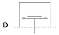
挿入デバイス1は、穿刺部材9の少なくとも一部がハウジング15から突出した第3位置即ち位置Dを介して、第4位置即ち位置Eに至る。この位置では、穿刺部材9は完全に突出している。穿刺部材9のこの突出は、挿入方向に本質的に長さ方向に少なくとも穿刺部材9の長さだけ移動することによって行われる。これは、穿刺部材9を全長に亘って挿入しなければならないためである。According to the invention, the
The
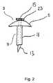
図2は、本発明による挿入器デバイスで挿入できる医療デバイス3の一実施例を示す。一般的には、このような医療デバイス3は、患者に挿入されないが患者の皮膚に載る本体5と、一つ又はそれ以上の穿刺部材9とを含む。図2に示す医療デバイス3は、穿刺部材9と導入器ニードル13とを含む軟質カニューレ11を持つポートデバイスセットである。例えば挿入ニードルを用いなければ挿入できない軟質カニューレの場合には、医療デバイス3の適用時に挿入ニードルを引っ込める。これは、導入器ニードル13を手作業で引っ込めるためのアタッチメント手段23を必要とする。これらは図2に示してある。他の医療デバイスは、穿刺性を持つカニューレを備えていてもよい。このカニューレは、医療デバイスの適用時に患者に挿入されたままである。 FIG. 2 shows an embodiment of a
本発明に従って挿入できる医療デバイスは、例えば、複数の注入セット又は一つの注入セットの注入部分、一つ又はそれ以上のセンサが挿入されたセンサデバイス、注射器又は穿刺部材を患者の皮下領域又は筋肉内領域に挿入した任意の他のデバイスによる繰り返し注射に代わる、アクセスが制限された本体しか持たないポートデバイスを含む。
多くの場合、医療デバイスを患者の皮膚と適切に接触するため、取り付けパッドを使用する。この取り付けパッドは、医療デバイス3の本体5の下側に取り付けられていてもよい。別の態様では、取り付けパッドを患者の皮膚に取り付け、医療デバイスを取り付けパッドを通して直接的に、又は取り付けパッドの開口部を通して挿入する。一般的には、取り付けパッドの接着剤の強さは、挿入後に医療デバイスを患者の皮膚に残し、医療デバイスをその場に残したまま挿入ニードル13だけをカニューレ11を通して取り外すのに十分な強さである。本発明の変形例では、医療デバイス3を第2医療デバイス3を通して挿入する。Medical devices that can be inserted in accordance with the present invention include, for example, multiple infusion sets or infusion portions of an infusion set, sensor devices into which one or more sensors are inserted, syringes or puncture members within a patient's subcutaneous region or muscle. Includes a port device with a limited access body to replace repeated injections by any other device inserted into the area.
In many cases, a mounting pad is used to properly contact the medical device with the patient's skin. This attachment pad may be attached to the lower side of the
図3は、本発明の別の実施例を示す。図3Aは、本発明による挿入デバイスのハウジングを示す。挿入デバイス1のハウジングは、上部分14及び下部分16の二つの部分を含む。両部分は、本質的に中空円筒形ジャケットの形状をなしている。二つの部分は、任意の断面を備えていてもよい。例えば、図3に示すように円筒形であってもよく、又は上部分14及び下部分16が互いに対応する限り、楕円形又は多角形、例えば正方形であってもよい。上部分14は頂部が頂部表面7によって閉鎖されている。上部分14の直径は下部分16の直径よりも大きく、これらの二つの部分は、高さがほぼ同じであり、上部分14が下部分16と重なる。 FIG. 3 shows another embodiment of the present invention. FIG. 3A shows the housing of the insertion device according to the invention. The housing of the
上部分14の下部分に向かって、回転/枢動手段を取り付けるため、通穴及び随意の支承体を含むアタッチメント手段29が設けられている。回転/枢動手段は、回転/枢動シャフト27用の円筒形の穴又は支承体を含む。これは上部分14内に取り付けられている。アタッチメント手段29は対称に配置されており、随意であるが直径方向両側に配置されている。
下部分16は、頂部も底部も閉鎖しておらず、垂直方向に、即ち挿入方向と平行に延びる一対の対称な案内スロット10を含む。これらの案内スロットは、下部分16の対角線の前後で対称である。案内スロット10は、回転/枢動シャフト27を案内するのに十分に大径であり、回転/枢動シャフト27を案内スロット10に沿って長さ方向に移動できる。上部分14及び下部分16は、前記回転/枢動シャフト27を介して連結される。An attachment means 29 including a through hole and an optional support is provided for mounting the rotation / pivoting means towards the lower part of the
The
図3Bは、穿刺部材9が図を見る人の方に向いた、医療デバイス3の平面図である。本体5の近位側、即ち医療デバイス3の適用時に患者の皮膚に面する側並びに取り付けパッド6が示してある。取り付けパッド6から突出した枢動/回転シャフト27の端部が見える。 FIG. 3B is a plan view of the
図3Cは、枢動/回転シャフト27に沿った、即ちこのシャフトと平行な、挿入デバイス1の断面図を示す。この図により、別の構成要素及び特徴が明らかになる。医療デバイス3の穿刺部材9は、閉鎖した円形の頂部表面7に向かって上方に向いている(即ち図1の位置1)。医療デバイス3は、デバイス取り付け手段18を介して枢動/回転シャフト27に解放自在に取り付けられている。本発明の一実施例によれば、医療デバイス3は、導入器ニードル13、及び前記導入器ニードル13とカニューレ11との間の摩擦によって、デバイス取り付け手段18に取り付けられている。導入器ニードル13は、医療デバイス3の挿入時に引っ込められる。導入器ニードル13とカニューレ11との間の摩擦により、デバイス取り付け手段18と医療デバイス3との間に、挿入前及び挿入中に、十分であり且つ適当な取り付けを提供する。十分であり且つ適当な取り付けというのは、医療デバイス3が、適用前(製造中、殺菌中、輸送中、及び貯蔵中)、又は挿入中に一つ又はそれ以上の回転及び/又は枢動によって生じる遠心力を含む適用中等に、例えばデバイス取り付け手段18又は導入器ニードル13から、意図せずに落下することがないということを意味する。十分であり且つ適当な取り付けというのは、更に、摩擦が余り高くなく、穿刺ニードル13を挿入後に引っ込めることができるということを意味する。かくして、導入器ニードル13の外径及びカニューレ9の内径の寸法並びにこれらの表面特性が、これに従って定められ且つ選択される。本発明の別の実施例によれば、医療デバイス3は、接着剤手段によってデバイス取り付け手段18及び/又は枢動/回転シャフト27に取り付けられる。接着剤手段の機能は、医療デバイス3とデバイス取り付け手段18及び/又は枢動/回転シャフト27との間に、医療デバイス3が挿入前及び挿入中に固定的に取り付けられた状態にとどまるが、挿入時に医療デバイス3を解放できるのに十分であり且つ適当な取り付け/接着を提供することである。接着剤手段は、これに従って選択され且つ寸法が定められる。 FIG. 3C shows a cross-sectional view of the
デバイス取り付け手段18の断面を図3Cに示す。枢動/回転シャフト27は、デバイス取り付け手段18を通って延びているか或いは、二つの独立した枢動/回転シャフト27が対称に且つデバイス取り付け手段18の各側で同じ枢動/回転軸線上で整合しているかのいずれかである。一対の案内手段19が、デバイス取り付け手段18の反対側の面に、即ち医療デバイス3に関して穿刺部材9の挿入方向から180°の方向に向いた面に取り付けられている。これらの案内手段19は、デバイス取り付け手段18の外周に向かって対称に位置決めされており、案内手段19間の距離は、医療デバイス3の直径よりも大きい。位置1では、枢動/回転シャフト27は、上部分14の頂部表面7並びに下部分16の開口部2と平行である。下部分16の開口部2は、この実施例では、シーリングデバイス4によって閉鎖されている。本発明の変形例では、シーリングデバイス4は取り付けパッドであってもよい。図示の実施例では、案内スロット10が下部分16の高さの約2/3に亘って延びている。別の態様では、案内スロット10は、穿刺部材9の長さと同じであってもよいし、これよりも長くてもよい。案内スロット10は上端10u及び下端10lを有する。枢動/回転シャフト27は、案内スロット10及び上部分14の開口部29を通って延びる。上部分14及び下部分16の高さは、各々、医療デバイス3の長さよりも大きい。 A cross section of the device attachment means 18 is shown in FIG. 3C. The pivot /
上案内手段19u及び下案内手段19lが設けられており、これらの案内手段は、下部分16の内面から垂直に、頂部表面7と本質的に平行に延びる。本発明の一実施例では、上案内手段19u及び下案内手段19lは円筒形である。本発明の別の実施例では、上案内手段19u及び下案内手段19lは本質的に楕円形である。更に別の実施例では、上案内手段19u及び下案内手段19lは正方形であり、随意であるが、縁部に丸味が付けてある。上案内手段19u及び下案内手段19lは、医療デバイス3が位置1にあるとき、デバイス取り付け手段及び案内手段19の下に位置決めされている。上案内手段19u及び下案内手段19lの長さは、デバイス取り付け手段を下げるとき、案内手段19と接触できるのに十分である。下部分16の外径とほぼ同じ直径を持つコイルばね25が上部分14の内側と下部分16との間に配置されている。コイルばね25は、上部分14の内面及び/又は円形の頂部表面7に取り付けられていてもよい。更に、コイルばね25は、遠位表面、例えば下部分16の壁の頂部表面20に載止していてもよいし、取り付けられていてもよい。挿入デバイスが位置1にある場合には、コイルばね25は、本質的に弛緩状態にあり、又は弛緩状態に近い状態にある。コイルばね25の作用により上部分14及び下部分16を最大に離間し、これらの部分の組み合わせキャビティの容積をほぼ最大にし、医療デバイス3を所定位置に、穿刺部材9が上を向いた状態、即ち図1の位置1に維持する。 Upper guide means 19u and lower guide means 19l are provided, which extend perpendicularly from the inner surface of the
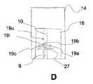
図3Dは、図1Eに示す第4位置と対応する一杯に挿入した位置で挿入デバイスを示す。この位置では、医療デバイス3は180°回転されており、穿刺部材9及び本体5が上部分14及び下部分16から突出しており、挿入デバイスが患者の皮膚にぴったりと当てて配置された場合に、穿刺部材9が一杯に挿入される。例えば圧力を上部分14に、下部分16に挿入する方向に加えることによって力を加えたとき、コイルばね25に力が蓄えられ、頂部表面7と下部分16の壁の頂部表面20との間で圧縮される。上部分14及び下部分16を互いに向かって移動し、かくして主キャビティ35の容積を最小にする。案内手段19を含むデバイス保持手段が取り付けられた回転/枢動シャフト27を下方に案内スロット10の下端10lまで、デバイスの挿入方向に移動し、上下の案内手段19u、19lを通過する。案内手段19、19u、19l及び回転/枢動手段27、18、29の連続的な作用又は組み合わせ作用及び相互作用、及び前方への移動により、医療デバイス3を約180°枢動/回転させ、長さ方向に移動する。従って、案内手段19は、次いで、上案内手段19u及び下案内手段19lの下にある。図3に示す実施例に示すように、デバイス取り付け手段18に配置された案内手段19及び19lは互いに接触する。 FIG. 3D shows the insertion device in the fully inserted position corresponding to the fourth position shown in FIG. 1E. In this position, the
コイルばね25は、その機能に従って選択され且つ寸法が定められる。コイルばね25の一つの機能は、医療デバイス3の穿刺部材9の挿入後に上部分14及び下部分16を分離するのに十分なエネルギを提供することである。本発明の一実施例によれば、コイルばね25は、挿入後に医療デバイス3を挿入デバイスから分離し、随意であるが、デバイス取り付け手段18及び枢動/回転シャフト27を開始位置に、又は図1の位置A又は位置B等の開始位置に近い位置に戻すのに十分なエネルギを提供する。本発明の別の実施例によれば、コイルばね25は、更に、穿刺ニードル13を患者に挿入した後で引っ込めるのに十分なエネルギを提供する。 The
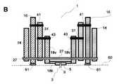
図4は、枢動/回転シャフト27に対して垂直な長さ方向断面図を示す。図4は、図3に示す実施例と同様の実施例を示すが、図3に示す角度に対して垂直方向から見た図である。図4では、案内手段及び枢動/回転手段の夫々の上述の作用及び相互作用が更に詳細に示してある。
挿入デバイス1は、上部分14及び下部分16を含み、上部分14は下部分16よりも広幅であり、上部分14は少なくとも部分的に下部分16と重なっている。これらの部分の形状(挿入デバイスの長さ方向軸線に対して垂直な断面)は、円筒形であってもよいし楕円形であってもよいし、矩形であってもよく、又は円形及び直線状輪郭の組み合わせでできていてもよい。本発明の一実施例では、断面は回転対称であり、又は少なくとも一つの対角線に関して対称であり、例えば鏡像対称(図示せず)である。FIG. 4 shows a longitudinal section perpendicular to the pivot /
The
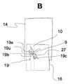
図4は、図3に示すのと本質的に同じ特徴を示す。しかしながら、この実施例では、デバイス取り付け手段18は、三つの別個の丸味のある突出部、即ち第1突出部19a、第2突出部19b、及び第3突出部19cを含む案内手段19を含む。第2突出部19bは、第1突出部19a及び第3突出部19cよりも長く、第1突出部19a及び第3突出部19cが第2突出部19bの側方に設けられている。第1突出部19a及び第3突出部19cは、第2突出部19bを中心として対称に位置決めされている。第2突出部19bの中心線は、回転/枢動シャフト27に対して垂直であり且つこのシャフトを通る軸線に沿って整合しており、穿刺部材9と整合している。前記軸線は、第1突出部19a及び第3突出部19cについての対称軸線でもある。 FIG. 4 shows essentially the same features as shown in FIG. However, in this embodiment, the device attachment means 18 includes guide means 19 including three separate rounded protrusions, namely a
図4Aは、医療デバイス3の穿刺部材9を第1位置で示す。この位置では、穿刺部材9は上方に向いており、挿入方向から180°の方向に差し向けられている。枢動/回転シャフト27は、案内スロット10の上端10uに位置決めされている。案内手段19u及び19lは、突出部19a、19b、又は19cと接触していない。 FIG. 4A shows the
図4Bは、医療デバイス3の穿刺部材9を、挿入方向から約135°離れた方向に向いた状態で示す。この位置は、上部分14に下向きの力を加え、これによって枢動/回転軸線27を挿入方向に案内し、この前方移動を枢動と組み合わせ、側方に案内し、約20°乃至70°又は約45°の(時計廻り方向)回転移動を提供するときに達成される。枢動/回転軸線27を下方に案内手段10に沿って移動し、案内手段10の上側1/3の辺りに位置決めする。このとき、中央突出部19bが案内手段19uと相互作用し及び/又は接触し、案内手段19uと案内手段19lとの間に配置される。両突出部19a及び19bは、これらの突出部19a及び19b間に配置された案内手段19uと相互作用し及び/又は接触する。 FIG. 4B shows the
図4Cは、上文中に説明したように下方への力を更に加えることにより、医療デバイス3及びデバイス取り付け手段18を約90°枢動/回転させることを示す。この位置では、案内手段19u及び19lは突出部19a、19b、及び19cと相互作用する。案内手段19uと19lとの間の距離は、好ましくは、突出部19bの幅と同じであるか或いはこれよりも大きいということが明らかになる。同様に、突出部19aと突出部19bとの間の距離、並びに突出部19bと突出部19cとの間の距離は、好ましくは、案内手段19u及び案内手段19lの夫々の直径と同じであるか或いはこれよりも大きい。 FIG. 4C shows that applying a further downward force as described above causes the
図4Dは、上文中に説明したように下方への力を更に加えることにより、上述の案内手段19u及び19lと突出部19a、19b、及び19cとの作用及び相互作用によって更に大きな枢動/回転が生じることを示す。回転は、穿刺手段が挿入方向と整合したときに停止する。図示の実施例では、更に90°回転/枢動し、回転/枢動による移動が180°になった後に停止する。最後の90°の回転は、大きな突出部19b及び小さな突出部19c及びこれらの突出部間の溝が下案内手段19lと相互作用することによって行われる。図示のように、挿入方向に更に下方に力を加えると、穿刺部材が所望の挿入方向に長さ方向に挿入される。長さ方向挿入移動の長さは、加えられた下方への力及び案内スロット10の長さによって制御される。案内スロットの下部分10lは、残りの挿入長さを、随意であるが、別の手段(図示していないし、説明していない)と組み合わせて決定する。 FIG. 4D shows that by further applying a downward force as described above, a greater pivot / rotation due to the action and interaction of the aforementioned guide means 19u and 19l with the
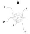
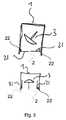
図5は、医療デバイス3及びその穿刺部材9を見えないように及びアクセスできないように保護し、シールドするための手段を示す。一つ又はそれ以上の保護手段21が、挿入デバイス1の内面に取り付け手段22によって取り付けられている。挿入デバイス1を作動するとき、即ち医療デバイス3の挿入プロセスで、これらの保護手段21が開口部2をシールドする位置から、保護手段21が医療デバイス3を通すことができる位置まで保護手段21を移動する。この移動は、一つ又はそれ以上の長さ方向移動、回転移動又は枢動を含み、これらの移動は連続的に又は同時に又は重ねて行われる。必要とされる作動手段は示してない。図5Bでは、保護手段21は上方に枢動しており、医療デバイス3を通すことができる。 FIG. 5 shows a means for protecting and shielding the
図6は、医療デバイス3を挿入するための本発明による挿入デバイス1の一実施例の断面図を示す。この断面は、穿刺部材9及び回転/枢動シャフト27の長さを通る、挿入方向での、即ち皮膚の表面60に対して垂直な断面である。
厚さや高さ等の様々な形状及び寸法が概略に示してある。図6Aでは、挿入デバイス1は、適用/挿入をいつでも行うことができる状態で示してあり、本体5及び穿刺部材9を含む医療デバイス3は上方を向いている、即ち患者から遠ざかる方向に向いている。挿入デバイス1は、(i)医療デバイス3の枢動/回転移動を提供し、次いで(ii)医療デバイス3を穿刺部材9の挿入方向に長さ方向に移動するための手段を含む。FIG. 6 shows a cross-sectional view of one embodiment of an
Various shapes and dimensions such as thickness and height are shown schematically. In FIG. 6A, the
本発明の一実施例では、医療デバイス3の枢動/回転移動は、挿入方向での長さ方向移動と同時に行われる。本発明の別の実施例では、医療デバイス3を、挿入方向でのその長さ方向移動とは別個に回転/枢動移動する回転手段が設けられている。別の実施例では、穿刺部材9が挿入方向に向いていない開始位置から、穿刺部材9が挿入方向に向いた第2位置まで医療デバイス3を回転/枢動する回転手段が設けられている。この回転/枢動移動は、本質的に、医療デバイス3を挿入方向に長さ方向に移動することなく行われる。回転/枢動移動の完了後、即ち穿刺部材9が挿入方向に整合したとき、挿入手段が医療デバイス3の穿刺部材9の長さ方向挿入を行う。 In one embodiment of the invention, the pivoting / rotating movement of the
図6に示す実施例では、前記挿入デバイス1は医療デバイス3の枢動/回転移動並びに医療デバイス3の長さ方向移動を提供するための手段を含む。前記手段は、図6Aのデバイスの上部分、即ち、デバイスを患者の皮膚に当てて位置決めしたが挿入前のデバイスの上部分を構成する上部分14と、実際に患者の皮膚と接触する図6Aの下部分を形成する下部分16と、枢動部材31と、垂直デバイス取り付け手段18vと、水平デバイス取り付け手段18hと、貫通シャフト27と、第1枢動シャフト41と、第2枢動シャフト43とを含む。下部分16、枢動部材31、及び垂直デバイス取り付け手段18vは、スロット(16s、31s、及び18sの夫々)を各々備えており、これらのスロットは、この図には示してない。挿入デバイスの実施例は、皮膚60の表面に対して本質的に垂直な、挿入方向が形成する軸線を中心として対称である。上部分14及び下部分16は、一つの部材の部分として示してないけれども、二つの別々の部品であってもよいし、同じ部品の部分であってもよい。垂直デバイス取り付け手段18vは二つの別々の部品であってもよいし、同じ部品の部分であってもよい。更に、垂直デバイス取り付け手段18v及び水平デバイス取り付け手段18hは、一つ、二つ、又はそれ以上の部品を含んでいてもよい。一実施例では、上部分14及び下部分16は、図3に示す実施例と同様に、円筒形形状であってもよい。貫通シャフト27が、上部分14、下部分16、枢動部材31、及び垂直デバイス取り付け手段18vを通って延びており、これらを連結する。第1枢動シャフト41は、下部分16及び枢動部材31を通って延びる。第2枢動シャフト43は、枢動部材31及び垂直デバイス取り付け手段18vを通って延びる。夫々のシャフト用の取り付け手段は示してない。一実施例では、一つ又はそれ以上のシャフトを回転できるように、一つ又はそれ以上の回転手段が設けられている。別の実施例では、一つ又はそれ以上のシャフトが、上部分14、下部分16、枢動部材31、又は垂直デバイス取り付け手段18vを含む群の少なくとも一つの部材に永久的に連結されている。図示の実施例では、貫通シャフト27及び第1及び第2の枢動シャフト41及び43は互いに平行であり、上部分14、下部分16、枢動部材31、及び垂直デバイス取り付け手段18vに対して垂直である。別の実施例では、貫通シャフト27、第1枢動シャフト41又は第2枢動シャフト43は、互いに平行でない。更に別の実施例では、上部分14、下部分16、枢動部材31、及び垂直デバイス取り付け手段18vを含む群から選択された少なくとも一つ又はそれ以上の部材が、前記群の少なくとも一つの他の部材と平行でない。 In the embodiment shown in FIG. 6, the
この実施例では、回転並びに長さ方向移動を提供するための前記手段の順番(挿入デバイスの外側から内側への方向で)は、上部分14、下部分16、枢動部材31、及び垂直デバイス取り付け手段18v及び水平デバイス取り付け手段18hである。別の実施例では、前記手段の順番は異なっていてもよく、第1及び第2の枢動シャフト41及び43が追加の部分及び/又は部材を貫通していてもよく、及び/又は貫通シャフト27が上掲の全ての部材を貫通していなくてもよい。
更に、図6に示す実施例では、挿入デバイスは、軟質部材61を含む。この部材は、下部分16の下端に取り付けられている。軟質部材61の機能は、下部分16の堅固な部分と患者の皮膚60の表面との間で緩衝体として作用し、これによって使用者の不快さを低減することである。この緩衝機能は、圧力を更に均等に分配すること、並びに皮膚上の体温よりも低温のデバイスを用いる場合に患者の不快感を低減することを含む。本発明の別の実施例では、軟質部材61がなくてもよい。In this embodiment, the order of the means for providing rotation and longitudinal movement (in the direction from the outside to the inside of the insertion device) is the
Further, in the embodiment shown in FIG. 6, the insertion device includes a
図6Bでは、図6Aに示す挿入デバイス1を、医療デバイス3を患者に適用し、穿刺部材9又は前記穿刺部材9の一部が患者の皮膚60の表面を穿刺した位置で示す。下部分16、枢動部材31、並びに第1及び第2の枢動シャフト41及び43だけが、図6Aにおけるのと本質的に同じ位置にあるということがわかる。デバイス取り付け手段18v及び18h、かくして、医療デバイス3が貫通シャフト27を中心として180°回転されている。これは、上部分14を押して力を加えることによって行われる。これによって、この力の大部分が貫通シャフト27に伝わり、これにより第1枢動シャフト41を中心として枢動部材31を枢動し、かくしてデバイス取り付け手段18を回転する。緩衝部材61は、図6Bでは、圧縮状態で示してあり、医療デバイス3の表面本体5が患者の皮膚60の表面と接触している。
デバイス取り付け手段18v及び18h及び医療デバイス3の回転移動及び長さ方向移動を生じるこの相互作用を図7及び図8を参照して以下に更に詳細に説明する。6B shows the
This interaction that causes the rotational and longitudinal movement of the device attachment means 18v and 18h and the
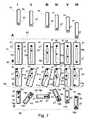
図7は、図6に示す挿入デバイス1の実施例の手段(A:上部分14、B:下部分16、C:枢動部材31、D:デバイス取り付け手段18v及び18h)の別の図を示す。水平デバイス取り付け手段18hの小さな部分しか示しておらず、医療デバイス3は示してない。位置I乃至VIは、
I: 開始位置
II: デバイス取り付け手段18v、18hを45°回転させた位置;
III: デバイス取り付け手段18v、18hを90°回転させた位置;
IV: デバイス取り付け手段18v、18hを135°回転させた位置;
V: デバイス取り付け手段18v、18hの180°回転させた位置;
VI: 最終位置(挿入位置)。7 shows another view of the means of the embodiment of the
I: Start position II: Position where the device attachment means 18v, 18h is rotated by 45 °;
III: Position of device attachment means 18v, 18h rotated 90 °;
IV: Position where the
V: Position of device attachment means 18v, 18h rotated 180 °;
VI: Final position (insertion position).
位置I及び位置VIは、図6A及び図6Bに示す位置と夫々対応する。図の方向は、挿入デバイス1の中央にあり且つ貫通シャフト27と平行な方向である。様々な部材の枢動/回転移動が明らかになり、及びこれらの部材の皮膚表面60からの夫々の距離がわかる。図示の手段の形状及び外寸法は、明瞭化を図るため、随意に選択されている。別の実施例では、外部分14には、挿入デバイス1の適用を容易にするため、ハンドル(図示せず)が設けられている。 The position I and the position VI correspond to the positions shown in FIGS. 6A and 6B, respectively. The direction shown is in the center of the
図7Aでは、上部分14を下に(即ち挿入方向に及び患者に向かって)押すことによって、貫通シャフト27が同様に下方に押されることが示してある。図示の実施例では、上部分14は、貫通シャフト27と同幅の又は貫通シャフト27よりも大径の開口部を有する。貫通シャフト27は、下端(患者に面する端部)に取り付けられているということがわかる。図示の実施例では、シャフトは固定されている。別の実施例では、シャフトは回転できる。位置Iは開始位置であり、この位置では、外部分14は、患者の皮膚の表面60から最も大きく離れている。位置VIでは、外部分14は、患者に最も近い。 FIG. 7A shows that by pushing the
図7Bは、下部分16が移動しないということを示す。下部分16は、患者の皮膚の表面60と接触した状態を維持する。制御スロット16s内の貫通シャフト27の6個の位置がわかる(I乃至VI)。制御スロット16sの上方の下部分16の上端に、第1枢動シャフト41を取り付けるための開口部が設けられている。図示の実施例では、この開口部は第1枢動シャフト41の直径よりも大径であり、前記第1枢動シャフト41は前記開口部内で回転できる。別の実施例では、第1枢動シャフト41は回転できない。挿入方向において、制御スロット16sが挿入方向と平行に下部分16に設けられている。貫通シャフト27は制御スロット16sによって取り囲まれており、上部分14及び貫通シャフト41が取り付けられているため、上部分14の移動の長さを制御する。スロットの長さは、挿入長さよりも長い。 FIG. 7B shows that the
図7Cは、案内スロット31sを持つ枢動部材31を示す。貫通部材27が案内スロット31s内で上下に移動できる。案内スロット31sの上方に第1枢動シャフト41が設けられており、枢動部材31は枢動軸線41を中心として枢動/回転できる。一実施例では、第1枢動シャフト41は下部分16に取り付けられており、枢動部材31は枢動軸線41用の開口部又は支承体を備えている。別の実施例では、第1枢動シャフト41は、枢動部材31に取り付けられている。案内スロット31sは、湾曲した開始部分を除き、直線状をなしている。案内スロット31sは、第2枢動シャフト43を設けることができるのに十分に湾曲しており、前記第2枢動シャフト43は、本質的に、枢動軸線41と、案内スロット31sの上開始点と、案内スロット31sの直線状下部分との間で一直線上に並ぶように位置決めされている。上部分14を下方に押すと、貫通シャフト27が下方に移動し、下部分16の制御スロット16sによって長さ方向下方に案内されるということは明らかである。枢動部材31は、下部分16に第1枢動シャフト41を通して連結されている。枢動部材31は、貫通シャフト27が下方に移動するときに枢動し(位置II)、この枢動は、案内スロット31sの開始点と終点との間の直線から案内スロット31sが最も大きく湾曲した離れた場所である位置IIIで最大に達する。更に下方に移動すると、枢動が減少する(位置IV)。貫通シャフト27が案内スロット31sの直線状下部分に達し、下方に移動するとき、枢動部材31の枢動は停止する(位置V乃至VI)。 FIG. 7C shows a
図7Dは、垂直デバイス取り付け手段18v及び水平デバイス取り付け手段18hの、開始位置Iから挿入位置VIまでの回転及び長さ方向移動を示す。垂直デバイス取り付け手段18vは、位置Iでは上方を向いており、位置V及びVIでは下方に、即ち患者の皮膚の表面60に向いている。垂直デバイス取り付け手段18vには、第2枢動シャフト43用の長さ方向案内スロット18s、及び貫通シャフト27を取り囲むのに十分に大径の開口部が設けられている。貫通シャフト27が下方に移動すると、枢動部材31が枢動し、かくして第2枢動シャフト43も枢動する。位置IIにおいて、これにより、水平デバイス取り付け手段18h及び垂直デバイス取り付け手段18vの回転/枢動移動を提供することがわかる。位置IIIにおいて、垂直デバイス取り付け手段18v及び水平デバイス取り付け手段18hは約90°回転されており、位置IVでは約135°回転されており、位置V及びVIでは約180°回転されている。回転速度は、本質的に、貫通シャフト27と第2枢動シャフト43との間の角度によって決定されるということは明らかである(図7Cと図7Dとを比較されたい)。貫通シャフト27と第2枢動シャフト43との間の距離は、位置I乃至VI中に変化する。案内スロット18sの長さは、挿入長さ(位置Vと位置VIとの間の差)よりも長い。 FIG. 7D shows the rotation and longitudinal movement of the vertical device mounting means 18v and the horizontal device mounting means 18h from the start position I to the insertion position VI. The vertical device attachment means 18v faces upwards at position I and downwards at positions V and VI, i.e. towards the
図8は、図7に示す挿入デバイスの6個の異なる位置(位置I乃至位置VI)での実施例の別の図を示す。断面を見る方向は、図6A及び図6Bに示す断面と同じであり、これらの図は図7の位置I乃至位置VIと夫々対応する。 FIG. 8 shows another view of the embodiment at six different positions (position I to position VI) of the insertion device shown in FIG. The direction of viewing the cross section is the same as the cross section shown in FIGS. 6A and 6B, and these figures correspond to positions I to VI in FIG. 7, respectively.
1 挿入デバイス
2 開口部
3 医療デバイス
5 医療デバイス本体
6 フラップ
7 底平面
9 穿刺部材
15 ハウジング
35 主キャビティDESCRIPTION OF
Claims (37)
Translated fromJapanese前記案内手段(10、19、16s、31s、18s)は前記穿刺部材(9)の前記第2位置から前記第3位置までの長さ方向移動を提供するようになっている、ことを特徴とする挿入器デバイス(1)。An inserter device (1) for inserting a piercing member (9) into the subcutaneous and / or intramuscular region of a patient, comprising a housing (15) surrounding the piercing member (9), the housing comprising: The insertion device (1) includes an upper part (14) and a lower part (16). The puncture member (9) protrudes from the housing (15) to the aligned second position, and one of the puncture members (9) to the third position where the puncture member (9) is aligned with the insertion direction or In an inserter device (1) comprising pivot means (27, 31, 41, 43) and guide means (10, 19, 16s, 31s, 18s) providing further pivoting,
The guide means (10, 19, 16s, 31s, 18s) are adapted to provide longitudinal movement of the puncture member (9) from the second position to the third position. Inserter device (1) to do.
前記枢動−案内手段(19、27、31、41、43、10、16s、31s、18s)は、長さ方向移動によって、前記穿刺エレメント(9)を患者に一杯に挿入した第4位置を提供し、前記長さ方向移動は、前記穿刺部材(9)の長さと同じであるか或いはこれよりも長い、挿入器デバイス(1)。The inserter device (1) according to claim 1,
The pivoting-guiding means (19, 27, 31, 41, 43, 10, 16s, 31s, 18s) are in a fourth position where the puncture element (9) is fully inserted into the patient by longitudinal movement. An inserter device (1) provided, wherein the longitudinal movement is equal to or longer than the length of the piercing member (9).
前記枢動手段は、一つ又はそれ以上のシャフト(27)を含む、挿入器デバイス(1)。Inserter device (1) according to claim 1 or 2,
The inserter device (1), wherein the pivot means comprises one or more shafts (27).
前記シャフト(27)は、前記上部分(14)及び前記下部分(16)を通って横方向に延びている、挿入器デバイス(1)。The inserter device (1) according to claim 3,
The inserter device (1), wherein the shaft (27) extends laterally through the upper part (14) and the lower part (16).
前記シャフト(27)は一つの貫通部材を含む、挿入器デバイス(1)。The inserter device (1) according to claim 4,
The inserter device (1), wherein the shaft (27) comprises one penetrating member.
前記シャフト(27)は二つ又はそれ以上の部品を含む、挿入器デバイス(1)。The inserter device (1) according to claim 4,
The inserter device (1), wherein the shaft (27) comprises two or more parts.
デバイス取り付け手段(18)が前記シャフト(27)に取り付けられており、前記デバイス取り付け手段(18)及び前記シャフト(27)は同じ回転中心を共有する、挿入器デバイス(1)。The inserter device (1) according to claim 5 or 6,
An inserter device (1), wherein a device attachment means (18) is attached to the shaft (27), the device attachment means (18) and the shaft (27) sharing the same center of rotation.
前記枢動手段は一つ又はそれ以上の枢動シャフト(41、43)及び一つ又はそれ以上の枢動部材(31)を含む、挿入器デバイス(1)。In the inserter device (1) according to any one of the preceding claims,
The inserter device (1), wherein the pivot means comprises one or more pivot shafts (41, 43) and one or more pivot members (31).
第1枢動シャフト(41)が前記下部分(16)及び枢動部材(31)を通って横方向に延びており、前記第1枢動シャフト(41)は、前記枢動部材(31)の回転中心である、挿入器デバイス(1)。The inserter device (1) according to claim 8,
A first pivot shaft (41) extends laterally through the lower portion (16) and a pivot member (31), the first pivot shaft (41) being connected to the pivot member (31). The inserter device (1), which is the center of rotation.
第2枢動シャフト(43)が前記枢動部材(31)及び前記デバイス取り付け手段(18)を通って横方向に延びている、挿入器デバイス(1)。The inserter device (1) according to claim 9,
An inserter device (1) in which a second pivot shaft (43) extends laterally through the pivot member (31) and the device attachment means (18).
前記案内手段は、一つ又はそれ以上の案内スロット(10、16s、18s)を含む、挿入器デバイス(1)。In an inserter device (1) according to any one of the preceding claims,
The inserter device (1), wherein the guiding means comprises one or more guiding slots (10, 16s, 18s).
前記案内スロット(10、16s)は前記下部分(16)に設けられており、前記案内スロット(10、16s)は前記挿入方向と平行であり、前記長さ方向移動の長さと同じ長さであるか或いはこれよりも長い、挿入器デバイス(1)。The inserter device (1) according to claim 11,
The guide slot (10, 16s) is provided in the lower portion (16), and the guide slot (10, 16s) is parallel to the insertion direction and has the same length as the lengthwise movement. An inserter device (1) that is or is longer.
前記案内スロット(10、16s)は前記シャフト(27)を取り囲み、前記シャフト(27)及び前記下部分(14)の長さ方向移動の長さを制限する、挿入器デバイス(1)。The inserter device (1) according to claim 12,
The inserter device (1), wherein the guide slot (10, 16s) surrounds the shaft (27) and limits the length of the longitudinal movement of the shaft (27) and the lower part (14).
前記案内スロット(31s)は前記枢動部材(31)に設けられており、前記案内スロット(31s)は、前記枢動部材(31)の上部分の湾曲部分、及び前記長さ方向移動と長さが同じであるか或いはこれよりも長い直線状部分を有し、前記案内スロット(31s)は、前記シャフト(27)を取り囲み、前記シャフト(27)の移動を制限する、挿入器デバイス(1)。The inserter device (1) according to any one of claims 1 to 13,
The guide slot (31s) is provided in the pivot member (31), and the guide slot (31s) includes a curved portion of an upper portion of the pivot member (31) and the lengthwise movement and length. An inserter device (1) having linear portions of the same length or longer than each other, the guide slot (31s) surrounding the shaft (27) and restricting the movement of the shaft (27) ).
前記案内スロット(18s)は、前記デバイス取り付け手段(18)の垂直部分(18v)内に設けられており、前記案内スロット(18s)は、前記長さ方向移動と長さが同じであるか或いはこれよりも長く、前記案内スロット(18s)は、前記第2枢動シャフト(43)を取り囲み、前記第2枢動シャフト(43)の移動を制限する、挿入器デバイス(1)。In an inserter device (1) according to any one of the preceding claims,
The guide slot (18s) is provided in a vertical part (18v) of the device mounting means (18), and the guide slot (18s) is the same in length as the longitudinal movement or Longer than this, the guide slot (18s) surrounds the second pivot shaft (43) and restricts the movement of the second pivot shaft (43).
下向きの力を前記上部分(14)に前記挿入方向に加えることにより、前記医療デバイス(3)を、前記下部分(16)の前記案内スロット(16s)及び前記枢動部材(31)の前記案内スロット(31s)によって案内された前記シャフト(27)の相互作用により、及び前記枢動部材(31)及び前記デバイス取り付け手段(18)の垂直部分(18v)に設けられた前記案内スロット(18s)によって案内される前記第1及び第2の枢動シャフト(41、43)の相互作用により、前記医療デバイス(3)を回転する、挿入器デバイス(1)。In an inserter device (1) according to any one of the preceding claims,
By applying a downward force to the upper part (14) in the insertion direction, the medical device (3) is moved into the guide slot (16s) of the lower part (16) and the pivoting member (31). The guide slot (18s) provided in the vertical part (18v) of the pivot member (31) and the device mounting means (18) by the interaction of the shaft (27) guided by the guide slot (31s). The inserter device (1), which rotates the medical device (3) by the interaction of the first and second pivot shafts (41, 43) guided by.
前記案内手段(19)は、前記デバイス取り付け手段(18)に設けられた一つ又はそれ以上の丸味のある突出部(19a、19b、19c)を含み、前記突出部(19a、19b、19c)は、前記挿入方向から遠ざかる方向に延びている、挿入器デバイス(1)。Inserter device (1) according to any one of claims 7 to 15,
The guide means (19) includes one or more rounded protrusions (19a, 19b, 19c) provided on the device attachment means (18), and the protrusions (19a, 19b, 19c). The inserter device (1) extends in a direction away from the insertion direction.
前記案内手段(19)は、主突出部(19b)及びこの主突出部の側方に対称に設けられた二つの副突出部(19a、19c)を含み、前記主突出部(19b)は、前記シャフト(27)に対して垂直な軸線に沿って前記穿刺部材(9)と整合している、挿入器デバイス(1)。The inserter device (1) according to claim 17,
The guide means (19) includes a main protrusion (19b) and two sub protrusions (19a, 19c) provided symmetrically to the sides of the main protrusion, and the main protrusion (19b) An inserter device (1) aligned with the piercing member (9) along an axis perpendicular to the shaft (27).
前記デバイスは、上案内手段(19u)及び下案内手段(19l)を含み、前記上下の案内手段(19u、19l)は前記下部分(16)の前記内面から延びている、挿入器デバイス(1)。Inserter device (1) according to claim 17 or 18,
The device comprises an upper guide means (19u) and a lower guide means (19l), the upper and lower guide means (19u, 19l) extending from the inner surface of the lower part (16). ).
前記上部分(14)に下向きの力を加えたとき、前記突出部(19a、19b、19c)と前記上下の案内手段(19u、19l)との間の相互作用により、前記医療デバイス(3)を回転する、挿入器デバイス(1)。The inserter device (1) according to claim 17, 18 or 19,
When a downward force is applied to the upper portion (14), the medical device (3) is caused by the interaction between the protrusions (19a, 19b, 19c) and the upper and lower guide means (19u, 19l). The inserter device (1).
前記穿刺部材(9)は、カニューレ(11)及び/又は導入器ニードル(13)を含む、挿入器デバイス(1)。In an inserter device (1) according to any one of the preceding claims,
The piercing member (9) comprises an cannula device (1) comprising a cannula (11) and / or an introducer needle (13).
前記導入器ニードル(13)は前記挿入器デバイスの部分であり、前記穿刺部材(9)の挿入後、前記導入器ニードル(13)を医療デバイス(3)から取り外す、挿入器デバイス(1)。The inserter device (1) according to claim 21,
An introducer device (1), wherein the introducer needle (13) is part of the inserter device and the introducer needle (13) is removed from the medical device (3) after insertion of the piercing member (9).
前記枢動−案内手段(27、31、41、43、10、16s、31s、18s、19)は、長さ方向移動により第5位置を提供し、随意であるが、この長さ方向移動は、枢動又は回転移動を伴い、この位置では、前記導入器ニードル(13)は、前記穿刺部材(9)を通して引っ込められる、挿入器デバイス(1)。The inserter device (1) according to claim 22,
Said pivot-guide means (27, 31, 41, 43, 10, 16s, 31s, 18s, 19) provide a fifth position by means of a longitudinal movement, optionally this longitudinal movement is In this position, with pivoting or rotational movement, the introducer needle (13) is retracted through the piercing member (9).
前記枢動−案内手段(19、27、31、41、43、10、16s、31s、18s)は、一つ又はそれ以上の線型移動及び一つ又はそれ以上の枢動により第5位置を提供し、この位置では、前記ニードル(13)は前記ハウジング(15)内に引っ込められる、挿入器デバイス(1)。The inserter device (1) according to claim 23,
Said pivot-guide means (19, 27, 31, 41, 43, 10, 16s, 31s, 18s) provide a fifth position by one or more linear movements and one or more pivots In this position, the inserter device (1), wherein the needle (13) is retracted into the housing (15).
前記導入器ニードル(13)は、前記ハウジング(15)内に引っ込められた後、もはや見えない、挿入器デバイス(1)。Inserter device (1) according to claim 22 or 23,
An introducer device (1), wherein the introducer needle (13) is no longer visible after being retracted into the housing (15).
前記穿刺部材(9)は、医療デバイス(3)の一部である、挿入器デバイス(1)。In an inserter device (1) according to any one of the preceding claims,
The puncture member (9) is an inserter device (1) that is part of a medical device (3).
前記医療デバイス(3)は、センサ、又は注入部分、又は流体を注射するためのゲートウェイ/ポートである、挿入器デバイス(1)。The inserter device (1) according to any one of claims 1 to 26,
The medical device (3) is an inserter device (1), which is a sensor or infusion part or gateway / port for injecting fluid.
前記挿入器デバイスは一回使用(使い捨て)である、挿入器デバイス(1)。In an inserter device (1) according to any one of the preceding claims,
The inserter device (1), wherein the inserter device is single use (disposable).
前記挿入器デバイスは繰り返し使用に適している、挿入器デバイス(1)。The inserter device (1) according to any one of the preceding claims,
The inserter device (1), which is suitable for repeated use.
前記挿入器デバイスは、様々な医療デバイスを同時に又は連続的に挿入するのに適している、挿入器デバイス(1)。The inserter device (1) according to any one of the preceding claims,
The inserter device (1) is suitable for inserting various medical devices simultaneously or sequentially.
前記挿入器デバイスは、使用前、使用後、又は使用間にクリーニング、消毒、及び/又は殺菌を行うことができる、挿入器デバイス(1)。Inserter device (1) according to any one of claims 1 to 30,
The inserter device (1) can be cleaned, disinfected and / or sterilized before use, after use or between uses.
前記穿刺部材(9)は、前記挿入器デバイスの「中央」に設けられていてもよいし、「中央」からずらして設けられていてもよい、挿入器デバイス(1)。The inserter device (1) according to any one of the preceding claims,
The puncture member (9) may be provided at the “center” of the inserter device, or may be provided shifted from the “center”.
前記挿入デバイス(1)は追加のカバー及び/又は保護手段(4、21)を含む、挿入器デバイス(1)。Inserter device (1) according to any one of the preceding claims,
The insertion device (1), wherein the insertion device (1) comprises an additional cover and / or protection means (4, 21).
前記中央挿入軸線は、前記挿入デバイスの前記中央軸線と平行である、挿入器デバイス(1)。The inserter device (1) according to any one of claims 1 to 33,
The inserter device (1), wherein the central insertion axis is parallel to the central axis of the insertion device.
前記穿刺部材(9)の前記中央挿入方向は、患者の皮膚の表面に対して本質的に垂直、即ち挿入角度αins が約0°であるか或いは、挿入角度が0°<αins <90°であるか或いは、10°<αins <80°であるか或いは、20°<αins <70°である、挿入器デバイス(1)。Inserter device (1) according to any one of the preceding claims,
The central insertion direction of the puncture member (9) is essentially perpendicular to the surface of the patient's skin, ie, the insertion angle αins is about 0 °, or the insertion angle is 0 ° <αins <90. An inserter device (1) that is either °, 10 ° <αins <80 °, or 20 ° <αins <70 °.
前記挿入器デバイスの前記中央軸線は、患者の皮膚の表面に対して本質的に垂直、即ち中央軸線のところでの角度αcenterが約0°であるか或いは、中央軸線のところでの角度が0°<αcenter<90°、又は10°<αcenter<90°、又は30°<αcenter<60°である、挿入器デバイス(1)。Inserter device (1) according to any one of the preceding claims, wherein
The central axis of the inserter device is essentially perpendicular to the surface of the patient's skin, ie, the angle αcenter at the central axis is about 0 °, or the angle at the central axis is 0 °. <[Alpha]center <90 [deg.], Or 10 [deg.] <[Alpha]center <90 [deg.], Or 30 [deg.] <[Alpha]center <60 [deg.].
前記穿刺部材(9)の前記挿入方向は、前記挿入器デバイスの前記中央軸線と平行である、即ち偏向角度αdefl=0°であるか或いは、0°<αdefl<90°、又は10°<αdefl<80°、又は30°<αdefl<60°である、挿入器デバイス(1)。The inserter device (1) according to any one of claims 1 to 36,
The insertion direction of the puncture member (9) is parallel to the central axis of the inserter device, ie the deflection angle αdefl = 0 °, or 0 ° <αdefl <90 ° or 10 ° <Αdefl <80 °, or 30 ° <αdefl <60 °, inserter device (1).
Applications Claiming Priority (3)
| Application Number | Priority Date | Filing Date | Title |
|---|---|---|---|
| US95051207P | 2007-07-18 | 2007-07-18 | |
| DKPA200701061 | 2007-07-18 | ||
| PCT/EP2008/058586WO2009010396A1 (en) | 2007-07-18 | 2008-07-03 | Insertion device with pivoting action |
Publications (2)
| Publication Number | Publication Date |
|---|---|
| JP2010533524Atrue JP2010533524A (en) | 2010-10-28 |
| JP2010533524A5 JP2010533524A5 (en) | 2011-09-08 |
Family
ID=38372447
Family Applications (1)
| Application Number | Title | Priority Date | Filing Date |
|---|---|---|---|
| JP2010516450AAbandonedJP2010533524A (en) | 2007-07-18 | 2008-07-03 | Insertion device with pivoting action |
Country Status (11)
| Country | Link |
|---|---|
| US (1) | US8246588B2 (en) |
| EP (1) | EP2175913A1 (en) |
| JP (1) | JP2010533524A (en) |
| KR (1) | KR20100049576A (en) |
| CN (1) | CN101801439A (en) |
| AU (1) | AU2008277763B2 (en) |
| CA (1) | CA2694952A1 (en) |
| IL (1) | IL202746A (en) |
| NZ (1) | NZ582226A (en) |
| RU (1) | RU2010105684A (en) |
| WO (1) | WO2009010396A1 (en) |
Families Citing this family (71)
| Publication number | Priority date | Publication date | Assignee | Title |
|---|---|---|---|---|
| US7381184B2 (en) | 2002-11-05 | 2008-06-03 | Abbott Diabetes Care Inc. | Sensor inserter assembly |
| USD902408S1 (en) | 2003-11-05 | 2020-11-17 | Abbott Diabetes Care Inc. | Analyte sensor control unit |
| MXPA06010784A (en) | 2004-03-26 | 2006-12-15 | Unomedical As | Injector device for infusion set. |
| US8062250B2 (en) | 2004-08-10 | 2011-11-22 | Unomedical A/S | Cannula device |
| US20090105569A1 (en) | 2006-04-28 | 2009-04-23 | Abbott Diabetes Care, Inc. | Introducer Assembly and Methods of Use |
| US9259175B2 (en) | 2006-10-23 | 2016-02-16 | Abbott Diabetes Care, Inc. | Flexible patch for fluid delivery and monitoring body analytes |
| US8571624B2 (en) | 2004-12-29 | 2013-10-29 | Abbott Diabetes Care Inc. | Method and apparatus for mounting a data transmission device in a communication system |
| US10226207B2 (en) | 2004-12-29 | 2019-03-12 | Abbott Diabetes Care Inc. | Sensor inserter having introducer |
| US7883464B2 (en) | 2005-09-30 | 2011-02-08 | Abbott Diabetes Care Inc. | Integrated transmitter unit and sensor introducer mechanism and methods of use |
| US8512243B2 (en) | 2005-09-30 | 2013-08-20 | Abbott Diabetes Care Inc. | Integrated introducer and transmitter assembly and methods of use |
| US8029441B2 (en) | 2006-02-28 | 2011-10-04 | Abbott Diabetes Care Inc. | Analyte sensor transmitter unit configuration for a data monitoring and management system |
| US9398882B2 (en) | 2005-09-30 | 2016-07-26 | Abbott Diabetes Care Inc. | Method and apparatus for providing analyte sensor and data processing device |
| US9788771B2 (en) | 2006-10-23 | 2017-10-17 | Abbott Diabetes Care Inc. | Variable speed sensor insertion devices and methods of use |
| US9743862B2 (en) | 2011-03-31 | 2017-08-29 | Abbott Diabetes Care Inc. | Systems and methods for transcutaneously implanting medical devices |
| US8333714B2 (en) | 2006-09-10 | 2012-12-18 | Abbott Diabetes Care Inc. | Method and system for providing an integrated analyte sensor insertion device and data processing unit |
| US7697967B2 (en) | 2005-12-28 | 2010-04-13 | Abbott Diabetes Care Inc. | Method and apparatus for providing analyte sensor insertion |
| US9572534B2 (en) | 2010-06-29 | 2017-02-21 | Abbott Diabetes Care Inc. | Devices, systems and methods for on-skin or on-body mounting of medical devices |
| US7731657B2 (en) | 2005-08-30 | 2010-06-08 | Abbott Diabetes Care Inc. | Analyte sensor introducer and methods of use |
| US7985199B2 (en) | 2005-03-17 | 2011-07-26 | Unomedical A/S | Gateway system |
| EP1762259B2 (en) | 2005-09-12 | 2025-01-01 | Unomedical A/S | Inserter for an infusion set with a first and second spring units |
| US9521968B2 (en) | 2005-09-30 | 2016-12-20 | Abbott Diabetes Care Inc. | Analyte sensor retention mechanism and methods of use |
| DK1962926T3 (en) | 2005-12-23 | 2009-09-28 | Unomedical As | injection device |
| US11298058B2 (en) | 2005-12-28 | 2022-04-12 | Abbott Diabetes Care Inc. | Method and apparatus for providing analyte sensor insertion |
| CA2636034A1 (en) | 2005-12-28 | 2007-10-25 | Abbott Diabetes Care Inc. | Medical device insertion |
| WO2007098771A2 (en) | 2006-02-28 | 2007-09-07 | Unomedical A/S | Inserter for infusion part and infusion part provided with needle protector |
| CA2653631A1 (en) | 2006-06-07 | 2007-12-13 | Unomedical A/S | Inserter |
| CA2653764A1 (en) | 2006-06-09 | 2007-12-13 | Unomedical A/S | Mounting pad |
| JP2009545341A (en) | 2006-08-02 | 2009-12-24 | ウノメディカル アクティーゼルスカブ | Cannula and delivery device |
| EP1917990A1 (en) | 2006-10-31 | 2008-05-07 | Unomedical A/S | Infusion set |
| WO2008150917A1 (en) | 2007-05-31 | 2008-12-11 | Abbott Diabetes Care, Inc. | Insertion devices and methods |
| EP2155311B1 (en) | 2007-06-20 | 2013-01-02 | Unomedical A/S | A method and an apparatus for making a catheter |
| AU2008270327A1 (en) | 2007-07-03 | 2009-01-08 | Unomedical A/S | Inserter having bistable equilibrium states |
| DE602008005153D1 (en) | 2007-07-10 | 2011-04-07 | Unomedical As | INSERT WITH TWO SPRINGS |
| ATE522240T1 (en) | 2008-02-13 | 2011-09-15 | Unomedical As | SEAL BETWEEN A CANNULAR PART AND A FLUID PATH |
| US9566384B2 (en) | 2008-02-20 | 2017-02-14 | Unomedical A/S | Insertion device with horizontally moving part |
| AU2009331635A1 (en) | 2008-12-22 | 2011-06-23 | Unomedical A/S | Medical device comprising adhesive pad |
| US9402544B2 (en) | 2009-02-03 | 2016-08-02 | Abbott Diabetes Care Inc. | Analyte sensor and apparatus for insertion of the sensor |
| AU2010277755A1 (en) | 2009-07-30 | 2012-02-02 | Unomedical A/S | Inserter device with horizontal moving part |
| KR20120047896A (en) | 2009-08-07 | 2012-05-14 | 우노메디컬 에이/에스 | Delivery device with sensor and one or more cannulas |
| EP3001194B1 (en) | 2009-08-31 | 2019-04-17 | Abbott Diabetes Care, Inc. | Medical devices and methods |
| WO2011041531A1 (en) | 2009-09-30 | 2011-04-07 | Abbott Diabetes Care Inc. | Interconnect for on-body analyte monitoring device |
| ATE553800T1 (en) | 2009-11-26 | 2012-05-15 | Hoffmann La Roche | EXTERNALLY TRIGGERABLE CANNULA ARRANGEMENT |
| USD924406S1 (en) | 2010-02-01 | 2021-07-06 | Abbott Diabetes Care Inc. | Analyte sensor inserter |
| LT3622883T (en) | 2010-03-24 | 2021-08-25 | Abbott Diabetes Care, Inc. | Medical device inserters and processes of inserting and using medical devices |
| KR20130018783A (en) | 2010-03-30 | 2013-02-25 | 우노메디컬 에이/에스 | Medical device |
| US11064921B2 (en) | 2010-06-29 | 2021-07-20 | Abbott Diabetes Care Inc. | Devices, systems and methods for on-skin or on-body mounting of medical devices |
| EP2433663A1 (en) | 2010-09-27 | 2012-03-28 | Unomedical A/S | Insertion system |
| EP2436412A1 (en) | 2010-10-04 | 2012-04-04 | Unomedical A/S | A sprinkler cannula |
| USD694397S1 (en) | 2011-02-28 | 2013-11-26 | Abbott Diabetes Care Inc. | Medical device inserter |
| EP2572741A1 (en) | 2011-09-23 | 2013-03-27 | Sanofi-Aventis Deutschland GmbH | Medicament delivery device and actuation mechanism for a drug delivery device |
| WO2013050277A1 (en) | 2011-10-05 | 2013-04-11 | Unomedical A/S | Inserter for simultaneous insertion of multiple transcutaneous parts |
| US9440051B2 (en) | 2011-10-27 | 2016-09-13 | Unomedical A/S | Inserter for a multiplicity of subcutaneous parts |
| CA2854003C (en) | 2011-11-07 | 2020-07-14 | Safety Syringes, Inc. | Contact trigger release needle guard |
| EP2713879B1 (en) | 2011-12-11 | 2017-07-26 | Abbott Diabetes Care, Inc. | Analyte sensor devices, connections, and methods |
| WO2014121119A1 (en) | 2013-02-01 | 2014-08-07 | Nxstage Medical, Inc. | Safe cannulation devices, methods, and systems |
| CH709930A2 (en) | 2014-07-29 | 2016-01-29 | Tecpharma Licensing Ag | Insertion device for an infusion. |
| WO2016183493A1 (en) | 2015-05-14 | 2016-11-17 | Abbott Diabetes Care Inc. | Compact medical device inserters and related systems and methods |
| US10213139B2 (en) | 2015-05-14 | 2019-02-26 | Abbott Diabetes Care Inc. | Systems, devices, and methods for assembling an applicator and sensor control device |
| EP4026488B1 (en) | 2015-12-30 | 2023-07-19 | Dexcom, Inc. | Transcutaneous analyte sensor systems and methods |
| US10702652B2 (en)* | 2016-11-15 | 2020-07-07 | Adam Teach | Injection device |
| US11071478B2 (en) | 2017-01-23 | 2021-07-27 | Abbott Diabetes Care Inc. | Systems, devices and methods for analyte sensor insertion |
| EP4111949B1 (en) | 2017-06-23 | 2023-07-26 | Dexcom, Inc. | Transcutaneous analyte sensors, applicators therefor, and needle hub comprising anti-rotation feature |
| US11331022B2 (en) | 2017-10-24 | 2022-05-17 | Dexcom, Inc. | Pre-connected analyte sensors |
| US20190120785A1 (en) | 2017-10-24 | 2019-04-25 | Dexcom, Inc. | Pre-connected analyte sensors |
| CN112423664B (en) | 2018-06-07 | 2025-01-21 | 雅培糖尿病护理公司 | Focused sterilization and sterilized sub-assemblies for analyte monitoring systems |
| USD926325S1 (en) | 2018-06-22 | 2021-07-27 | Dexcom, Inc. | Wearable medical monitoring device |
| CA3126999A1 (en) | 2019-02-22 | 2020-08-27 | Deka Products Limited Partnership | Infusion set and inserter assembly systems and methods |
| USD1002852S1 (en) | 2019-06-06 | 2023-10-24 | Abbott Diabetes Care Inc. | Analyte sensor device |
| CA3188510A1 (en) | 2020-08-31 | 2022-03-03 | Vivek S. RAO | Systems, devices, and methods for analyte sensor insertion |
| USD999913S1 (en) | 2020-12-21 | 2023-09-26 | Abbott Diabetes Care Inc | Analyte sensor inserter |
| USD1013864S1 (en) | 2021-08-26 | 2024-02-06 | Deka Products Limited Partnership | Fluid administration apparatus assembly |
Family Cites Families (514)
| Publication number | Priority date | Publication date | Assignee | Title |
|---|---|---|---|---|
| US2047010A (en) | 1935-01-30 | 1936-07-07 | Fairleigh S Dickinson | Automatic syringe injector |
| US2295849A (en) | 1940-10-25 | 1942-09-15 | Gustave L Kayden | Attachment for hypodermic syringes |
| US2690529A (en) | 1950-03-01 | 1954-09-28 | Bofors Ab | Suspension arrangement for movable members |
| US2972779A (en)* | 1954-06-07 | 1961-02-28 | Baxter Don Inc | Plastic tubing process |
| US3074541A (en)* | 1959-10-13 | 1963-01-22 | Brunswick Corp | Medicinal vial and needle assembly |
| DE1133507B (en) | 1960-03-29 | 1962-07-19 | Bundesrep Deutschland | Injection device |
| US3221739A (en) | 1962-03-26 | 1965-12-07 | Rosenthal Sol Roy | Injection device |
| US3221740A (en) | 1962-08-31 | 1965-12-07 | Rosenthal Sol Roy | Injection device |
| US3306291A (en)* | 1964-04-14 | 1967-02-28 | Burron Medical Prod Inc | Disposable sterile syringes, needle containers and the like having prestressed frangible portions therein |
| US3610240A (en) | 1967-06-13 | 1971-10-05 | American Hospital Supply Corp | Intravenous catheter apparatus with catheter telescoped inside puncturing cannula |
| US3547119A (en) | 1967-12-08 | 1970-12-15 | Baxter Laboratories Inc | Catheter assembly |
| US3485352A (en) | 1968-08-12 | 1969-12-23 | American Hospital Supply Corp | Package for sterile medical catheter |
| US3670727A (en) | 1970-04-16 | 1972-06-20 | American Hospital Supply Corp | Medical infusion set |
| US3810469A (en) | 1972-05-24 | 1974-05-14 | Ampoules Inc | Multiple compartment hypodermic devices |
| US3840011A (en) | 1973-08-06 | 1974-10-08 | F Wright | Adjustable syringe dose aid |
| US3986508A (en) | 1973-08-22 | 1976-10-19 | Abcor, Inc. | Sterilizable, medical connector for blood processing |
| US4022205A (en) | 1973-11-05 | 1977-05-10 | Tenczar Francis J | Fluid connectors |
| US3893448A (en) | 1973-11-26 | 1975-07-08 | John W Brantigan | Catheter device for use in detecting gas in body fluids and tissue |
| US3937219A (en)* | 1974-01-14 | 1976-02-10 | Karakashian Nubar A | Sterile syringe assembly and method of making same |
| US3995518A (en) | 1975-08-28 | 1976-12-07 | Spiroff Carl M | Means and methods for punching holes in catheters |
| US4267836A (en) | 1976-11-12 | 1981-05-19 | Whitney Douglass G | Injection device and method |
| GB1580924A (en)* | 1977-06-24 | 1980-12-10 | Smiths Industries Ltd | Methods of hole-forming in plastics workpieces and products manufactured using such methods |
| US4188950A (en)* | 1978-10-30 | 1980-02-19 | Wardlaw Stephen C | Disposable syringe |
| US4201406A (en) | 1978-11-13 | 1980-05-06 | Baxter Travenol Laboratories, Inc. | Spike connector for solution bag |
| US4227528A (en) | 1978-12-26 | 1980-10-14 | Wardlaw Stephen C | Automatic disposable hypodermic syringe |
| US4334551A (en) | 1979-04-30 | 1982-06-15 | Becton Dickinson & Company | Connector |
| US4333455A (en) | 1979-12-26 | 1982-06-08 | Sherwood Medical Industries Inc. | Injectable catheter and method of placing same |
| US4315505A (en)* | 1980-04-07 | 1982-02-16 | Shiley, Inc. | Tracheostomy tube with disposable inner cannula |
| GB2088215B (en) | 1980-06-10 | 1984-11-28 | Wallace Ltd H G | Improvements in intravascular devices |
| USD267199S (en) | 1980-07-17 | 1982-12-07 | Abbott Laboratories | Vial and solution container connecting device |
| SE426023B (en) | 1981-04-23 | 1982-12-06 | Bengt Gustavsson | DEVICE BLA FOR INFANTRY OF CATHEDRES IN BLOOD BLOOD |
| US4417886A (en) | 1981-11-05 | 1983-11-29 | Arrow International, Inc. | Catheter introduction set |
| US4464178A (en) | 1981-11-25 | 1984-08-07 | Dalton Michael J | Method and apparatus for administration of fluids |
| US4378015A (en)* | 1981-12-21 | 1983-03-29 | Wardlaw Stephen C | Automatic injecting syringe |
| US4473369A (en) | 1982-01-11 | 1984-09-25 | Baxter Travenol Laboratories, Inc. | Continuous ambulatory peritoneal dialysis clamping system |
| US4500312A (en)* | 1982-12-15 | 1985-02-19 | Mcfarlane Richard H | Connecting assembly |
| US4530695A (en) | 1982-12-31 | 1985-07-23 | N.J. Phillips Pty. Limited | Injector |
| USRE32922E (en) | 1983-01-13 | 1989-05-16 | Paul D. Levin | Blood sampling instrument |
| US4531937A (en) | 1983-01-24 | 1985-07-30 | Pacesetter Systems, Inc. | Introducer catheter apparatus and method of use |
| NZ206837A (en) | 1983-01-27 | 1986-08-08 | Johnson & Johnson Prod Inc | Thin film adhesive dressing:backing material in three sections |
| NL8300386A (en) | 1983-02-02 | 1984-09-03 | Steritech Bv | STERILE DEVICE CONNECTING TWO ROOMS. |
| US4525157A (en) | 1983-07-28 | 1985-06-25 | Manresa, Inc. | Closed system catheter with guide wire |
| US4484910A (en) | 1983-12-21 | 1984-11-27 | Survival Technology, Inc. | Dual mode automatic injector |
| US4563177A (en)* | 1983-12-22 | 1986-01-07 | Kamen Dean L | Catheter stabilization pad |
| US4617019A (en) | 1984-09-28 | 1986-10-14 | Sherwood Medical Company | Catheter |
| US4713059A (en) | 1984-10-11 | 1987-12-15 | American Hospital Supply Corporation | Dispenser for an elongated flexible member |
| US4850974A (en) | 1984-10-11 | 1989-07-25 | Baxter International Inc. | Dispenser and method for an elongated flexible member |
| GB2176402B (en)* | 1985-06-20 | 1989-04-19 | Craig Med Prod Ltd | Wound management appliance for use on the human skin |
| US4755173A (en) | 1986-02-25 | 1988-07-05 | Pacesetter Infusion, Ltd. | Soft cannula subcutaneous injection set |
| CA1272423A (en) | 1986-02-25 | 1990-08-07 | Peter C. Lord | Soft cannula subcutaneous injection set and method of making same |
| US4878897A (en) | 1986-05-15 | 1989-11-07 | Ideation Enterprises, Inc. | Injection site device having a safety shield |
| GB8618578D0 (en) | 1986-07-30 | 1986-09-10 | Turner R C | Lancet device |
| GB8627808D0 (en) | 1986-11-20 | 1986-12-17 | Cox J A | Sampling liquids from human/animal body |
| US4734092A (en)* | 1987-02-18 | 1988-03-29 | Ivac Corporation | Ambulatory drug delivery device |
| US4895570A (en)* | 1987-06-05 | 1990-01-23 | Abbott Laboratories | Locking port shroud for peritoneal dialysis tubing connector |
| US4838871A (en) | 1987-07-17 | 1989-06-13 | Luther Ronald B | Needle guard, and assembly |
| US4950252A (en) | 1987-11-02 | 1990-08-21 | Luther Medical Products, Inc. | Single hand actuated locking safety catheter and method of use |
| US5248301A (en) | 1987-12-03 | 1993-09-28 | Medfusion, Inc. | Transcutaneous infusion apparatus and methods of manufacture and use |
| US4850996A (en) | 1988-02-22 | 1989-07-25 | Cree Ian C | Safety needle |
| US5067496A (en) | 1988-04-07 | 1991-11-26 | Shiley Incorporated | Tracheostomy tube |
| US4978338A (en) | 1988-04-21 | 1990-12-18 | Therex Corp. | Implantable infusion apparatus |
| US4840613A (en) | 1988-04-27 | 1989-06-20 | Menlo Care, Inc. | Protective sheath for catheter assembly |
| US4950163A (en) | 1988-05-19 | 1990-08-21 | Zimble Alan W | Dental syringe for treating gums |
| GB8812096D0 (en)* | 1988-05-21 | 1988-06-22 | Smith & Nephew Ass | Adhesive sheet |
| US4894054A (en)* | 1988-06-20 | 1990-01-16 | Miskinyar Shir A | Preloaded automatic disposable syringe |
| US5020665A (en) | 1988-07-01 | 1991-06-04 | John Bruno | Storage/carrying devices for transport of hypodermic needle/syringe assemblies to bedside use and ultimate disposal |
| US5172808A (en) | 1988-07-01 | 1992-12-22 | John Bruno | Device for safely transporting one or more hypodermic needles or the like from point of use to point of ultimate disposal |
| US4863016A (en) | 1988-07-25 | 1989-09-05 | Abbott Laboratories | Packaging for a sterilizable calibratable medical device |
| NL8802106A (en) | 1988-08-26 | 1990-03-16 | Abraham Van Den Haak | NEEDLE PROTECTION FOR AN INJECTION SYRINGE. |
| CA2001732A1 (en) | 1988-10-31 | 1990-04-30 | Lawrence A. Lynn | Intravenous line coupling device |
| FR2638359A1 (en) | 1988-11-03 | 1990-05-04 | Tino Dalto | SYRINGE GUIDE WITH ADJUSTMENT OF DEPTH DEPTH OF NEEDLE IN SKIN |
| US4986817A (en)* | 1988-11-22 | 1991-01-22 | International Development Systems, Inc. | Hypodermic syringe sheath holder and needle guide |
| USRE34223E (en) | 1989-02-08 | 1993-04-13 | Care Medical Devices, Inc. | Catheter inserter |
| US4917669A (en) | 1989-02-08 | 1990-04-17 | Safetyject | Catheter inserter |
| US5054499A (en) | 1989-03-27 | 1991-10-08 | Swierczek Remi D | Disposable skin perforator and blood testing device |
| GB8909395D0 (en) | 1989-04-25 | 1989-06-14 | Simpla Plastics | A catheter |
| US5011475A (en) | 1989-06-02 | 1991-04-30 | Olson Richard A | Protector for intravenous and syringe needles |
| US5205820A (en) | 1989-06-16 | 1993-04-27 | Science, Incorporated | Fluid delivery apparatus |
| US5702371A (en) | 1989-07-24 | 1997-12-30 | Venetec International, Inc. | Tube fitting anchoring system |
| US5112313A (en) | 1989-08-11 | 1992-05-12 | Sallee Patricia L | IV cover/protector |
| US5282793A (en)* | 1989-10-02 | 1994-02-01 | Larson Eldon E | Syringe holder and applicator |
| US4994042A (en)* | 1989-10-02 | 1991-02-19 | Vadher Dinesh L | Combined catheter and needle |
| GB8926825D0 (en) | 1989-11-28 | 1990-01-17 | Glaxo Group Ltd | Device |
| US4970954A (en)* | 1990-01-09 | 1990-11-20 | Richard E. Hewitt | Self inking hand stamp |
| US5129884A (en) | 1990-01-16 | 1992-07-14 | Dysarz Edward D | Trap in barrel one handed retracted intervenous catheter device |
| US5024662A (en) | 1990-03-13 | 1991-06-18 | Menes Cesar M | Resistance syringe for epidural anesthesia |
| US5121751A (en) | 1990-03-16 | 1992-06-16 | Ryder International Corporation | Instrument for tissue sampling |
| IE911031A1 (en) | 1990-04-03 | 1991-10-23 | Knutson Richard A | Closed system intravenous catheter |
| US5222947A (en)* | 1990-04-18 | 1993-06-29 | Amico Elio D | Self recapping injection needle assembly |
| US4994045A (en)* | 1990-04-20 | 1991-02-19 | Sherwood Medical Company | Split sleeve safety syringe |
| US5188611A (en)* | 1990-05-31 | 1993-02-23 | Orgain Peter A | Safety sheath for needles, sharp instruments and tools |
| US4982842A (en)* | 1990-06-04 | 1991-01-08 | Concord/Portex | Safety needle container |
| US5116325A (en) | 1990-06-06 | 1992-05-26 | Paterson Donald W | Needle assembly |
| US5098389A (en)* | 1990-06-28 | 1992-03-24 | Becton, Dickinson And Company | Hypodermic needle assembly |
| US5279591A (en)* | 1990-07-16 | 1994-01-18 | Simon Alexander Z | Protector for needle catheter |
| US5232454A (en) | 1990-08-01 | 1993-08-03 | Smiths Industries Medical Systems, Inc. | Safety needle container |
| US5176662A (en)* | 1990-08-23 | 1993-01-05 | Minimed Technologies, Ltd. | Subcutaneous injection set with improved cannula mounting arrangement |
| NO173261C (en) | 1990-09-07 | 1993-11-24 | Bent Heimreid | Intravenously! Skanyle |
| AR245372A1 (en) | 1990-12-04 | 1994-01-31 | Arcusin Sa | Safety sheath for hypodermic syringes. |
| GB9100819D0 (en)* | 1991-01-15 | 1991-02-27 | Medimech Int Ltd | Subcutaneous injector |
| US5092853A (en)* | 1991-02-04 | 1992-03-03 | Couvertier Ii Douglas | Automatic retractable medical needle and method |
| US5176643A (en)* | 1991-04-29 | 1993-01-05 | George C. Kramer | System and method for rapid vascular drug delivery |
| US5451210A (en) | 1991-04-29 | 1995-09-19 | Lifequest Medical, Inc. | System and method for rapid vascular drug delivery |
| US5271744A (en) | 1991-04-29 | 1993-12-21 | George C. Kramer | System and method for rapid vascular drug delivery |
| GB9111600D0 (en) | 1991-05-30 | 1991-07-24 | Owen Mumford Ltd | Improvements relating to injection devices |
| US5147375A (en) | 1991-05-31 | 1992-09-15 | Ann Sullivan | Safety finger prick instrument |
| US5645076A (en) | 1991-08-14 | 1997-07-08 | Yoon; Inbae | Automatic retractable safety penetrating instrument |
| US5186712A (en)* | 1991-08-23 | 1993-02-16 | Kansas Creative Devices, Inc. | Intravenous catheter launching device |
| GB9120416D0 (en) | 1991-09-25 | 1991-11-06 | Sterimatic Holdings Ltd | Catheter placement units |
| US5256152A (en) | 1991-10-29 | 1993-10-26 | Marks Lloyd A | Safety needle and method of using same |
| US5207647A (en) | 1991-11-05 | 1993-05-04 | Phelps David Y | Needle device |
| CA2123400A1 (en) | 1991-11-12 | 1993-05-27 | Urs A. Ramel | Lancet device |
| US5312359A (en) | 1991-12-03 | 1994-05-17 | Wallace Henry G | Intravenous cannula insertion assembly with protective shield |
| US5807316A (en) | 1991-12-06 | 1998-09-15 | Teeple, Jr.; Edward | Method and apparatus for preparing and administering intravenous anesthesia infusions |
| US5163915A (en) | 1992-01-07 | 1992-11-17 | Barry Holleron | Safety needle set |
| US5324302A (en) | 1992-10-13 | 1994-06-28 | Sherwood Medical Company | Lancet with locking cover |
| US5176650A (en)* | 1992-02-10 | 1993-01-05 | Haining Michael L | Intravenous catheter and insertion device |
| US5403288A (en) | 1992-02-13 | 1995-04-04 | Stanners; Sydney D. | Safety sleeve for dental syringe |
| US5256149A (en) | 1992-02-14 | 1993-10-26 | Ethicon, Inc. | Trocar having transparent cannula and method of using |
| US5316246A (en) | 1992-03-23 | 1994-05-31 | Scott/Ross Designs Inc. | Intravenous tube holder |
| DE4212723C1 (en) | 1992-04-16 | 1993-11-04 | Arta Plast Ab Tyresoe | LANCETTE DEVICE FOR POINTING THE SKIN |
| US5372592A (en) | 1992-06-22 | 1994-12-13 | C. R. Bard, Inc. | Method and device for preparing catheters prior to use |
| EP0588228A1 (en) | 1992-09-12 | 1994-03-23 | Ralf Ritter | Sterilizable container for single medical and surgical sets and instruments |
| US5993470A (en) | 1992-09-15 | 1999-11-30 | Yoon; Inbae | Universal handle for medical instruments |
| US5269799A (en) | 1992-11-05 | 1993-12-14 | Daniel Richard F | Finger pricker |
| DE69330374T2 (en) | 1992-11-10 | 2002-05-02 | Seikagaku Kogyo K.K., Tokio/Tokyo | INJECTOR AND ITS APPLICATION |
| SE502537C2 (en) | 1992-11-26 | 1995-11-06 | Boc Ohmeda Ab | Device for infusion cannula |
| IT227703Y1 (en) | 1992-12-16 | 1997-12-15 | S I F Ra Societa Italiana Farm | PACKAGE OF A DISPOSABLE GROUP FOR THE INFUSION OF A MEDICAL LIQUID IN THE BODY OF A PATIENT. |
| US5342324A (en) | 1993-01-08 | 1994-08-30 | Device Labs, Inc. | Needle device |
| DK169711B1 (en)* | 1993-01-15 | 1995-01-23 | Coloplast As | A dressing |
| US5545143A (en) | 1993-01-21 | 1996-08-13 | T. S. I. Medical | Device for subcutaneous medication delivery |
| US5919170A (en) | 1993-02-01 | 1999-07-06 | Mentor Corporation | Urinary catheter |
| US5354280A (en) | 1993-02-19 | 1994-10-11 | Habley Medical Technology Corporation | Trocar and seal arrangement |
| US5387197A (en)* | 1993-02-25 | 1995-02-07 | Ethicon, Inc. | Trocar safety shield locking mechanism |
| DK25793A (en) | 1993-03-09 | 1994-09-10 | Pharma Plast Int As | Infusion set for intermittent or continuous administration of a therapeutic agent |
| EP0693946B1 (en)* | 1993-03-24 | 2001-05-16 | Owen Mumford Limited | Improvements relating to injection devices |
| DK39293D0 (en) | 1993-04-01 | 1993-04-01 | Novo Nordisk As | DISPENSES PROTECTED FOR RECYCLING |
| US5257980A (en) | 1993-04-05 | 1993-11-02 | Minimed Technologies, Ltd. | Subcutaneous injection set with crimp-free soft cannula |
| GB9310163D0 (en) | 1993-05-18 | 1993-06-30 | Owen Mumford Ltd | Improvements relating to injection devices |
| US5540664A (en) | 1993-05-27 | 1996-07-30 | Washington Biotech Corporation | Reloadable automatic or manual emergency injection system |
| US5697907A (en) | 1993-07-20 | 1997-12-16 | Graphic Controls Corporation | Safety catheter |
| US5417659A (en) | 1993-07-20 | 1995-05-23 | Devon Industries, Inc. | Surgical instrument sharp end foil |
| US5390669A (en)* | 1993-08-09 | 1995-02-21 | Mallinckrodt Medical, Inc. | Device using connector tube to lock inner cannula inside outer cannula |
| JP3494183B2 (en) | 1993-08-10 | 2004-02-03 | 株式会社アドバンス | Simple blood collection device |
| US5342319A (en) | 1993-08-17 | 1994-08-30 | Watson Robert L | Transdermal injection appliance |
| US5562629A (en) | 1993-08-31 | 1996-10-08 | Haughton; Victor M. | Catheter placement system utilizing a handle, a sharp, and a releasable retainer mechanism providing retraction of the sharp upon disengagement of the catheter from the handle |
| WO1996032981A1 (en) | 1995-04-17 | 1996-10-24 | Med Design Corporation | Safety stylet for intravenous catheter insertion |
| CA2132277C (en) | 1993-10-22 | 2005-05-10 | Giorgio Cirelli | Injection device |
| GB9323121D0 (en) | 1993-11-09 | 1994-01-05 | Smiths Industries Plc | Needle protection assemblies |
| CA2135706C (en) | 1993-11-15 | 1999-06-15 | Walter E. Cover | Retractable-needle cannula insertion set with refinements to better control leakage, retraction speed, and reuse |
| US5833666A (en) | 1993-11-23 | 1998-11-10 | Uresil Corporation | Catheter fixation assembly |
| DE69431369T2 (en) | 1993-12-10 | 2003-05-15 | The Boc Group Plc, Windlesham | venous cannula |
| US5439473A (en) | 1993-12-13 | 1995-08-08 | Modulohm A/S | Safety lancet |
| US5350392A (en) | 1994-02-03 | 1994-09-27 | Miles Inc. | Lancing device with automatic cocking |
| US5429607A (en) | 1994-03-09 | 1995-07-04 | I-Flow Corporation | Elastomeric syringe actuation device |
| US5573510A (en) | 1994-02-28 | 1996-11-12 | Isaacson; Dennis R. | Safety intravenous catheter assembly with automatically retractable needle |
| US5405332A (en) | 1994-03-28 | 1995-04-11 | Opalek; A. Allen | Shield apparatus for syringe needle |
| IL109294A (en)* | 1994-04-12 | 1998-02-08 | Wais Med Ltd | Surgical instrument for impact insertion of an intraosseous trocar- needle |
| USD362718S (en) | 1994-04-22 | 1995-09-26 | Mcgaw, Inc. | Turn lock cannula |
| US5685859A (en) | 1994-06-02 | 1997-11-11 | Nikomed Aps | Device for fixating a drainage tube and a drainage tube assembly |
| US5562636A (en) | 1994-07-15 | 1996-10-08 | Utterberg; David S. | Needle protector sheath |
| US5490841A (en)* | 1994-07-29 | 1996-02-13 | Landis; Robert M. | Safety sheath device |
| US5505709A (en) | 1994-09-15 | 1996-04-09 | Minimed, Inc., A Delaware Corporation | Mated infusion pump and syringe |
| CA2157999C (en) | 1994-09-23 | 1999-08-03 | Robert B. Odell | Manually pivoted barrier assembly for a piercing element |
| US5507730A (en) | 1994-10-04 | 1996-04-16 | Habley Medical Technology Corporation | One-piece glass prefilled syringe system |
| US5449349A (en) | 1994-10-14 | 1995-09-12 | Sallee; Wayne A. | Intravenous needle cover/protector |
| FR2725902B1 (en) | 1994-10-21 | 1997-01-10 | M2Ct | PROTECTION DEVICE FOR A TUBULAR NEEDLE |
| US5545152A (en) | 1994-10-28 | 1996-08-13 | Minimed Inc. | Quick-connect coupling for a medication infusion system |
| JPH08187286A (en) | 1994-11-11 | 1996-07-23 | Ikufumi Yamada | Intravascular indwelling needle with separate take out opening for inner tube |
| US5628765A (en) | 1994-11-29 | 1997-05-13 | Apls Co., Ltd. | Lancet assembly |
| US5501675A (en)* | 1994-12-27 | 1996-03-26 | Becton, Dickinson And Company | Safety catheter assembly having safety stop push button |
| ATE269739T1 (en) | 1994-12-28 | 2004-07-15 | Abbott Lab | INTRODUCTION DEVICE WITH VALVE FOR A CATHETER |
| US5836917A (en)* | 1995-01-10 | 1998-11-17 | Specialized Health Products, Inc. | Self retracting medical needle apparatus and methods |
| US5823997A (en) | 1995-01-10 | 1998-10-20 | Specialized Health Products, Inc. | Medical needle safety apparatus and methods |
| GB9501218D0 (en) | 1995-01-21 | 1995-03-15 | Boc Group Plc | Medical devices |
| US5586553A (en) | 1995-02-16 | 1996-12-24 | Minimed Inc. | Transcutaneous sensor insertion set |
| CA2168615A1 (en) | 1995-03-07 | 1996-09-08 | Timothy J. Erskine | Catheter-advancement actuated needle retraction system |
| FR2733155B1 (en) | 1995-04-18 | 1997-09-19 | Tebro | RECHARGEABLE SELF-INJECTOR |
| US5554130A (en) | 1995-05-17 | 1996-09-10 | Creative Bio Tech, Inc. | Stick-free syringe and associated methods |
| US5584816A (en) | 1995-05-25 | 1996-12-17 | Becton, Dickinson And Company | Hardpack shield for a pivoting needle guard |
| US5584813A (en) | 1995-06-07 | 1996-12-17 | Minimed Inc. | Subcutaneous injection set |
| US5643216A (en) | 1995-06-08 | 1997-07-01 | White; James E. | Patient bracelet having catheter capture integrally formed therewith and methods of making the same |
| JPH11508465A (en) | 1995-07-06 | 1999-07-27 | ディセトロニック・ライセンシング・アクチェンゲゼルシャフト | Disposable cassette connected to liquid chemical infusion pump |
| DE19525607A1 (en) | 1995-07-14 | 1997-01-16 | Boehringer Ingelheim Kg | Transcorneal drug delivery system |
| IT1277390B1 (en) | 1995-07-28 | 1997-11-10 | Fatro Spa | SYRINGE FOR THE INTRAMAMMARY ADMINISTRATION OF A VETERINARY DRUG COMPOSITION |
| PL309932A1 (en) | 1995-08-07 | 1997-02-17 | Henryk Bursig | Device for protecting a needle especially disposable injection needle |
| US5599318A (en)* | 1995-08-29 | 1997-02-04 | Becton, Dickinson And Company | Needle shield assembly having a releasable lock |
| US5611576A (en) | 1995-11-24 | 1997-03-18 | Industrie Borla Spa | Female coupling element for haemodialysis medical equipment |
| US5599315A (en)* | 1995-12-01 | 1997-02-04 | Charles J. McPhee | Syringe actuation device |
| ZA9610374B (en)* | 1995-12-11 | 1997-06-23 | Elan Med Tech | Cartridge-based drug delivery device |
| US5830187A (en) | 1995-12-22 | 1998-11-03 | Science Incorporated | Fluid delivery device with conformable ullage and fill assembly |
| US5865806A (en)* | 1996-04-04 | 1999-02-02 | Becton Dickinson And Company | One step catheter advancement automatic needle retraction system |
| US5704920A (en)* | 1996-05-17 | 1998-01-06 | Becton, Dickinson And Company | Manually driven needle shield assembly |
| US5913846A (en) | 1996-06-13 | 1999-06-22 | Becton, Dickinson And Company | Shielded needle assembly |
| US5807351A (en) | 1996-06-17 | 1998-09-15 | Safegard Medical Products, Inc. | Protection device for sharp objects |
| US6230051B1 (en) | 1996-06-18 | 2001-05-08 | Alza Corporation | Device for enhancing transdermal agent delivery or sampling |
| US5752923A (en) | 1996-06-24 | 1998-05-19 | Medical Device Technologies, Inc. | Biopsy instrument with handle and needle set |
| US5741288A (en) | 1996-06-27 | 1998-04-21 | Chemtrak, Inc. | Re-armable single-user safety finger stick device having reset for multiple use by a single patient |
| US5665075A (en) | 1996-07-03 | 1997-09-09 | Becton, Dickinson And Company | Method of making a needle shield assembly |
| US5916199A (en) | 1996-07-11 | 1999-06-29 | Miles; John E. | Tapeless tubing anchoring system with intravenous applications |
| US5681323A (en) | 1996-07-15 | 1997-10-28 | Arick; Daniel S. | Emergency cricothyrotomy tube insertion |
| US5738641A (en) | 1996-07-31 | 1998-04-14 | Watson; Robert L. | Blood withdrawal patch |
| US5643220A (en) | 1996-08-19 | 1997-07-01 | Cosme; Edgar Z. | Needle assembly |
| US5899886A (en) | 1997-07-07 | 1999-05-04 | Cosme; Edgar Z. | Puncture safe needle assembly |
| JPH10179734A (en) | 1996-10-25 | 1998-07-07 | Terumo Corp | Intravenous cannula assembly |
| US5947935A (en) | 1996-11-12 | 1999-09-07 | Medrad, Inc. | Syringes, syringe plungers and injector systems |
| US5944694A (en) | 1996-11-12 | 1999-08-31 | Medrad, Inc. | Prefillable syringes and injectors for use therewith |
| US5817058A (en) | 1996-12-23 | 1998-10-06 | Shaw; Thomas J. | Retractable catheter introducer structure |
| US6607509B2 (en)* | 1997-12-31 | 2003-08-19 | Medtronic Minimed, Inc. | Insertion device for an insertion set and method of using the same |
| US5851197A (en) | 1997-02-05 | 1998-12-22 | Minimed Inc. | Injector for a subcutaneous infusion set |
| US7329239B2 (en) | 1997-02-05 | 2008-02-12 | Medtronic Minimed, Inc. | Insertion device for an insertion set and method of using the same |
| US6093172A (en) | 1997-02-05 | 2000-07-25 | Minimed Inc. | Injector for a subcutaneous insertion set |
| US20070142776A9 (en)* | 1997-02-05 | 2007-06-21 | Medtronic Minimed, Inc. | Insertion device for an insertion set and method of using the same |
| GB9708569D0 (en) | 1997-04-29 | 1997-06-18 | Smiths Industries Ltd | Catheter and needle assemblies |
| US5954643A (en) | 1997-06-09 | 1999-09-21 | Minimid Inc. | Insertion set for a transcutaneous sensor |
| US5968011A (en) | 1997-06-20 | 1999-10-19 | Maersk Medical A/S | Subcutaneous injection set |
| CA2239515C (en) | 1997-08-12 | 2006-09-05 | Genesis Medical Technologies, Inc. | Spring-actuated needleless injector |
| US6120482A (en) | 1997-09-09 | 2000-09-19 | Becton, Dickinson And Company | Pivotable guard for shielding a needle |
| DE19740187C1 (en) | 1997-09-12 | 1999-04-15 | Disetronic Licensing Ag | Dosing unit, e.g. for medicines |
| US5843001A (en) | 1997-09-17 | 1998-12-01 | Goldenberg; Alec | Connector for a replaceable biopsy needle |
| CH692543A5 (en) | 1997-09-25 | 2002-07-31 | Disetronic Licensing Ag | Dispenser with auto switch. |
| US6375641B2 (en) | 1997-10-01 | 2002-04-23 | Dr. Japan Co., Ltd. | Medical anesthetic needle |
| US6361523B1 (en) | 1998-03-27 | 2002-03-26 | Venetec International, Inc. | Anchoring system for a medical article |
| US6045534A (en) | 1997-10-27 | 2000-04-04 | Sarcos, Inc. | Disposable fluid injection module |
| US6077244A (en) | 1998-04-30 | 2000-06-20 | Mdc Investment Holdings, Inc. | Catheter insertion device with retractable needle |
| US6224571B1 (en)* | 1997-11-14 | 2001-05-01 | Venetec International, Inc. | Medical line securement device |
| EP1037687B8 (en) | 1997-12-11 | 2008-10-22 | Alza Corporation | Device for enhancing transdermal agent flux |
| US6086008A (en) | 1997-12-22 | 2000-07-11 | Deka Products Limited Partnership | Apparatus and method for permitting introduction and withdrawal of a catheter |
| WO1999033504A1 (en) | 1997-12-31 | 1999-07-08 | Minimed Inc. | Insertion device for an insertion set and method of using the same |
| JP4194754B2 (en) | 1998-01-12 | 2008-12-10 | モルソエ,クラウス | Syringe |
| US6093179A (en) | 1998-01-21 | 2000-07-25 | Abbott Laboratories | Apparatus and method for placement of a percutaneous endoscopic gastrostomy tube |
| US5925032A (en) | 1998-02-17 | 1999-07-20 | Alcon Laboratories, Inc. | Syringe cannula holder |
| US5957895A (en) | 1998-02-20 | 1999-09-28 | Becton Dickinson And Company | Low-profile automatic injection device with self-emptying reservoir |
| US6056718A (en)* | 1998-03-04 | 2000-05-02 | Minimed Inc. | Medication infusion set |
| US5975120A (en) | 1998-03-05 | 1999-11-02 | Novosel; Lorraine Ley | Automatically retractable gas tubing feed spool |
| US5957892A (en) | 1998-03-12 | 1999-09-28 | Specialized Health Products, Inc. | Safety catheter insertion apparatus and methods |
| US6123690A (en) | 1998-03-20 | 2000-09-26 | Maersk Medical A/S | Subcutaneous infusion device |
| US5980506A (en) | 1998-03-20 | 1999-11-09 | Mathiasen; Orla | Subcutaneous infusion device |
| US6086575A (en) | 1998-03-20 | 2000-07-11 | Maersk Medical A/S | Subcutaneous infusion device |
| DE29905072U1 (en) | 1998-03-20 | 1999-09-09 | Maersk Medical A/S, Lynge | Subcutaneous infusion device |
| US5919167A (en) | 1998-04-08 | 1999-07-06 | Ferring Pharmaceuticals | Disposable micropump |
| GB9808408D0 (en) | 1998-04-18 | 1998-06-17 | Owen Mumford Ltd | Improvements relating to injection devices |
| USD417733S (en) | 1998-04-28 | 1999-12-14 | Becton, Dickinson And Company | Catheter introducer needle assembly |
| USD421119S (en)* | 1998-04-28 | 2000-02-22 | Becton, Dickinson And Company | Introducer needle |
| DE19821723C2 (en) | 1998-05-14 | 2000-07-06 | Disetronic Licensing Ag | Catheter head for subcutaneous administration of an active ingredient |
| US6949084B2 (en) | 1998-05-14 | 2005-09-27 | Disetronic Licensing Ag | Catheter head for subcutaneous administration of an active substance |
| DE19822031C2 (en) | 1998-05-15 | 2000-03-23 | Disetronic Licensing Ag | Auto injection device |
| US6183464B1 (en)* | 1998-06-01 | 2001-02-06 | Inviro Medical Devices Ltd. | Safety syringe with retractable needle and universal luer coupling |
| US6503231B1 (en)* | 1998-06-10 | 2003-01-07 | Georgia Tech Research Corporation | Microneedle device for transport of molecules across tissue |
| US6736797B1 (en) | 1998-06-19 | 2004-05-18 | Unomedical A/S | Subcutaneous infusion set |
| WO2000002614A1 (en) | 1998-07-08 | 2000-01-20 | Becton Dickinson And Company | Sealable safety catheter having a combination needle retraction chamber and needle cover |
| US6355021B1 (en)* | 1998-07-14 | 2002-03-12 | Maersk Medical A/S | Medical puncturing device |
| USD526409S1 (en) | 1998-07-14 | 2006-08-08 | Unomedical A/S | Medical puncturing device |
| TW372674U (en) | 1998-07-21 | 1999-10-21 | Cotron Corp | Earphone storage case |
| FR2781378B1 (en) | 1998-07-23 | 2001-02-16 | Stephane Chanut | PROTECTED AND EASILY EXTRACTED NEEDLE DEVICE |
| US6547762B1 (en) | 1999-05-13 | 2003-04-15 | Mdc Investment Holdings, Inc. | Retractable needle medical device |
| US6554798B1 (en) | 1998-08-18 | 2003-04-29 | Medtronic Minimed, Inc. | External infusion device with remote programming, bolus estimator and/or vibration alarm capabilities |
| EP1360970A1 (en) | 1998-08-28 | 2003-11-12 | Becton, Dickinson and Company | Method for using a safety shield assembly and related combinations thereof |
| US6074371A (en) | 1998-09-10 | 2000-06-13 | Magnolia Medical, Llc | Blunt injection needle for a pen-type injector |
| IT1311489B1 (en) | 1998-10-12 | 2002-03-13 | Francesco Rigon | DEVICE FOR PROTECTION AFTER THE USE OF A HYPODERMIC NEEDLE, PARTICULARLY OF THE BUTTERFLY TYPE. |
| US20020173748A1 (en) | 1998-10-29 | 2002-11-21 | Mcconnell Susan | Reservoir connector |
| US6248093B1 (en) | 1998-10-29 | 2001-06-19 | Minimed Inc. | Compact pump drive system |
| US6191338B1 (en)* | 1998-11-19 | 2001-02-20 | Kurt Haller | Adhesive bandage, matrix, and methods of removal |
| GB2344054B (en) | 1998-11-28 | 2003-02-19 | Smiths Industries Plc | Catheter retainers and assemblies |
| JP2000180442A (en) | 1998-12-15 | 2000-06-30 | Fuji Photo Film Co Ltd | Hemofilter |
| US6105218A (en) | 1998-12-16 | 2000-08-22 | Siemens Medical Systems, Inc. | Snap-type fastening device |
| US6050976A (en) | 1998-12-23 | 2000-04-18 | Specialized Health Products, Inc. | In-line retractable safety catheter needle insertion assembly |
| US6334857B1 (en) | 1999-01-11 | 2002-01-01 | Sims Portex Inc. | Needle protection apparatus used with a vial |
| AU2750400A (en) | 1999-02-01 | 2000-08-18 | Neldon C. Wagner | Adhesive pad with flexible release paper |
| US6042570A (en) | 1999-02-11 | 2000-03-28 | Dsu Medical Corporation | Needle point protection sheath |
| US6620136B1 (en) | 1999-02-18 | 2003-09-16 | Medsafe Technologies, Llc | Retractable I-V catheter placement device |
| US20040069044A1 (en) | 1999-04-29 | 2004-04-15 | Gilad Lavi | Device for measuring a volume of drug |
| US6039629A (en)* | 1999-05-06 | 2000-03-21 | Mitchell; Julia | Nursing pad |
| US6450992B1 (en) | 1999-07-02 | 2002-09-17 | Smith & Nephew, Inc. | Cannula interface |
| US6837877B2 (en)* | 1999-08-23 | 2005-01-04 | Becton, Dickinson And Company | Safety shield assembly |
| US6623457B1 (en) | 1999-09-22 | 2003-09-23 | Becton, Dickinson And Company | Method and apparatus for the transdermal administration of a substance |
| AU1153701A (en) | 1999-10-28 | 2001-05-08 | William Anthony Denne | Disposable jet injector |
| US6517508B1 (en) | 1999-11-03 | 2003-02-11 | Dsu Medical Corporation | Set for blood processing |
| US7198618B2 (en)* | 1999-11-04 | 2007-04-03 | Tyco Healthcare Group Lp | Safety shield for medical needles |
| US6280420B1 (en) | 1999-11-04 | 2001-08-28 | Specialized Health Products | Reaccessible medical needle safety devices and methods |
| AU1649100A (en) | 1999-12-08 | 2001-06-18 | Union Medico | Injection device |
| US6776775B1 (en) | 1999-12-23 | 2004-08-17 | Owais Mohammad | Hypodermic syringe needle assembly and method of making the same |
| US6749589B1 (en) | 2000-01-18 | 2004-06-15 | Sterling Medications, Inc. | Subcutaneous injection set for use with a reservoir that has a septum |
| US20020120231A1 (en) | 2000-01-18 | 2002-08-29 | Douglas Joel S. | Subcutaneous injection set with secondary injection septum |
| WO2001054758A1 (en) | 2000-01-27 | 2001-08-02 | Afra Design Pty. Limited | A single-use syringe |
| CN1206964C (en) | 2000-01-28 | 2005-06-22 | 科洛普拉斯特公司 | Collecting bag |
| US6221058B1 (en) | 2000-02-01 | 2001-04-24 | Wang-Hsiang Kao | Structure for infusion catheter needle |
| CA2331030A1 (en) | 2000-02-16 | 2001-08-16 | Roche Diagnostics Gmbh | Hypodermic needleless injection system |
| ES2220734T3 (en) | 2000-02-24 | 2004-12-16 | Venetec International, Inc. | UNIVERSAL FIXING SYSTEM FOR CATETER. |
| DE10008826C2 (en) | 2000-02-25 | 2002-03-14 | Disetronic Licensing Ag | Micro perfusion device with collection container |
| US6572588B1 (en) | 2000-03-10 | 2003-06-03 | Venetec International, Inc. | Medical anchoring system |
| JP2003527932A (en) | 2000-03-29 | 2003-09-24 | エラン・ファルマ・インターナショナル・リミテッド | Needle assembly and sheath and method of filling drug delivery device |
| PL191428B1 (en) | 2000-04-06 | 2006-05-31 | Htl Strefa Sp Z Oo | Puncturing depth adjusting assembly for puncturing devices |
| US6485461B1 (en) | 2000-04-04 | 2002-11-26 | Insulet, Inc. | Disposable infusion device |
| US6629949B1 (en) | 2000-05-08 | 2003-10-07 | Sterling Medivations, Inc. | Micro infusion drug delivery device |
| US6659982B2 (en) | 2000-05-08 | 2003-12-09 | Sterling Medivations, Inc. | Micro infusion drug delivery device |
| DK1289586T3 (en) | 2000-05-15 | 2008-01-28 | Ares Trading Sa | Container for needle for syringe |
| US6443183B1 (en) | 2000-06-07 | 2002-09-03 | Transcend Inc. | Valve and assembly for axially movable members |
| US6517517B1 (en)* | 2000-06-08 | 2003-02-11 | Mayo Foundation For Medical Education And Research | Automated injection device for administration of liquid medicament |
| US7530964B2 (en)* | 2000-06-30 | 2009-05-12 | Elan Pharma International Limited | Needle device and method thereof |
| JP2002028246A (en) | 2000-07-13 | 2002-01-29 | Mitsubishi Pencil Co Ltd | Safety device for intravenous cannula |
| US6440096B1 (en) | 2000-07-14 | 2002-08-27 | Becton, Dickinson And Co. | Microdevice and method of manufacturing a microdevice |
| US6572586B1 (en) | 2000-07-25 | 2003-06-03 | Animas Corporation | Low profile infusion set |
| US6589229B1 (en) | 2000-07-31 | 2003-07-08 | Becton, Dickinson And Company | Wearable, self-contained drug infusion device |
| US6986760B2 (en)* | 2000-08-02 | 2006-01-17 | Becton, Dickinson And Company | Pen needle and safety shield system |
| US6702779B2 (en)* | 2000-08-18 | 2004-03-09 | Becton, Dickinson And Company | Constant rate fluid delivery device with selectable flow rate and titratable bolus button |
| US6790199B1 (en) | 2000-09-28 | 2004-09-14 | North American Medical Products, Inc. | Needle protective assembly for multi-draw needle |
| US6503222B2 (en)* | 2000-09-28 | 2003-01-07 | Pfizer Inc | Oral dosage dispenser |
| GB2370506B (en) | 2000-10-04 | 2005-02-16 | Biocompatibles Ltd | Catheter tip |
| SE0003672D0 (en) | 2000-10-12 | 2000-10-12 | Astrazeneca Ab | Package |
| US6808514B2 (en) | 2000-10-17 | 2004-10-26 | Patricia G. Schneider | Emergency medical dispensing card |
| WO2002045771A2 (en) | 2000-11-09 | 2002-06-13 | Biovalve Technologies, Inc. | Microneedle adapter |
| ES2281457T3 (en) | 2000-11-09 | 2007-10-01 | Insulet Corporation | TRANSCUTANEOUS SUPPLY MEDIA. |
| US20020072720A1 (en) | 2000-12-11 | 2002-06-13 | Hague Clifford W. | Rigid soluble materials for use with needle-less infusion sets, sensor sets and injection devices and methods of making the same |
| US9302903B2 (en) | 2000-12-14 | 2016-04-05 | Georgia Tech Research Corporation | Microneedle devices and production thereof |
| US7052483B2 (en) | 2000-12-19 | 2006-05-30 | Animas Corporation | Transcutaneous inserter for low-profile infusion sets |
| US6387078B1 (en) | 2000-12-21 | 2002-05-14 | Gillespie, Iii Richard D. | Automatic mixing and injecting apparatus |
| US6579267B2 (en) | 2001-01-05 | 2003-06-17 | Applied Diabetes Research, Inc. | Pivoting joint infusion assembly |
| US7083597B2 (en)* | 2001-01-05 | 2006-08-01 | Applied Diabetes Research, Inc. | Pivoting joint infusion system with seal |
| US6837878B2 (en)* | 2001-01-09 | 2005-01-04 | Icu Medical, Inc. | Bluntable needle assembly with open-ended blunting probe |
| US6811545B2 (en) | 2001-01-31 | 2004-11-02 | Vincent L. Vaillancourt | Safety needle |
| KR200232249Y1 (en) | 2001-02-03 | 2001-10-25 | 이춘발 | Disposable Safety Syringe without Remainder |
| US6500155B2 (en) | 2001-02-13 | 2002-12-31 | Churchill Medical Systems, Inc. | Safety angled indwelling needle and a protective shield for a safety angled indwelling needle |
| EP1381408A4 (en) | 2001-02-22 | 2007-06-13 | Insulet Corp | Modular infusion device and method |
| IL157561A0 (en) | 2001-03-04 | 2004-03-28 | Sterling Medivations Inc | Infusion hub assembly and fluid line disconnect system |
| US6984213B2 (en) | 2001-03-15 | 2006-01-10 | Specialized Health Products, Inc. | Biopsy needle device |
| DE10117285B4 (en) | 2001-04-06 | 2016-08-04 | Roche Diabetes Care Gmbh | cannula system |
| DE10117286A1 (en) | 2001-04-06 | 2002-10-17 | Disetronic Licensing Ag | Soft cannula |
| EP1383560B2 (en) | 2001-04-06 | 2023-04-26 | F. Hoffmann-La Roche AG | Infusion set |
| US20020161332A1 (en) | 2001-04-13 | 2002-10-31 | Kirk Ramey | Infusion set with tape |
| JP2003010329A (en) | 2001-04-24 | 2003-01-14 | Mitsubishi Pencil Co Ltd | Needle covering member and syringe equipped therewith |
| JP2003010326A (en) | 2001-04-24 | 2003-01-14 | Mitsubishi Pencil Co Ltd | Needle protector assemblage, syringe equipped therewith and needle hub |
| US6461362B1 (en) | 2001-04-30 | 2002-10-08 | Mdc Investment Holdings, Inc. | Catheter insertion device with retractable needle |
| DK1256358T3 (en) | 2001-05-09 | 2005-01-10 | Unomedical As | Infusion device for administration of a therapeutic drug |
| US6824530B2 (en) | 2001-05-11 | 2004-11-30 | Harmac Medical Products, Inc. | Combination needle assembly and needle safety guard |
| EP1815879A3 (en)* | 2001-05-18 | 2007-11-14 | Deka Products Limited Partnership | Infusion set for a fluid pump |
| WO2002100467A2 (en) | 2001-06-08 | 2002-12-19 | Eli Lilly And Company | Needle hiding assembly for a medication injector |
| AUPR568901A0 (en) | 2001-06-14 | 2001-07-12 | Occupational & Medical Innovations Ltd | A retractable needle assembly for a catheter and which uses an elastomeric member to retract the needle |
| US6582397B2 (en) | 2001-06-19 | 2003-06-24 | Portex, Inc. | Needle safety device with antiremoval protection |
| JP3771819B2 (en) | 2001-07-18 | 2006-04-26 | 株式会社トップ | Wing needle protector |
| GB0118419D0 (en) | 2001-07-28 | 2001-09-19 | Owen Mumford Ltd | Improvements relating to injection devices |
| DE10139291A1 (en) | 2001-08-09 | 2003-02-20 | Sartorius Gmbh | Packaging unit, in particular, for throw away filters comprises a housing and a cover element which has a central piercing point and at least one planned tearing line |
| US6607511B2 (en) | 2001-08-09 | 2003-08-19 | Mdc Investment Holdings, Inc. | Medical device with safety flexible needle |
| SE0102736D0 (en) | 2001-08-14 | 2001-08-14 | Patrick Griss | Side opened out-of-plane microneedles for microfluidic transdermal interfacing and fabrication process of side opened out-of-plane microneedles |
| US7186236B2 (en) | 2001-09-07 | 2007-03-06 | Medtronic Minimed, Inc. | Infusion device and inlet structure for same |
| US6994213B2 (en)* | 2001-09-18 | 2006-02-07 | Becton, Dickinson And Company | Packaging for push button blood collection set |
| US20030088238A1 (en) | 2001-09-26 | 2003-05-08 | Poulsen Jens Ulrik | Modular drug delivery system |
| US6830562B2 (en)* | 2001-09-27 | 2004-12-14 | Unomedical A/S | Injector device for placing a subcutaneous infusion set |
| US20030109829A1 (en) | 2001-09-28 | 2003-06-12 | Mogensen Lasse Wesseltoft | Injector device for placing a subcutaneous infusion set |
| US6689100B2 (en) | 2001-10-05 | 2004-02-10 | Becton, Dickinson And Company | Microdevice and method of delivering or withdrawing a substance through the skin of an animal |
| US20040078028A1 (en) | 2001-11-09 | 2004-04-22 | Flaherty J. Christopher | Plunger assembly for patient infusion device |
| US20030105430A1 (en) | 2001-11-30 | 2003-06-05 | Elan Pharma International Limited Wil House | Automatic injector |
| US6726649B2 (en) | 2001-12-28 | 2004-04-27 | Becton, Dickinson And Company | Medical needle assemblies |
| ITTO20011228A1 (en) | 2001-12-28 | 2003-06-28 | Cane Srl | DISPOSABLE NEEDLE CONTAINER. |
| GB2396560B (en) | 2002-01-14 | 2005-01-05 | Future Top Medical Environment | Protecting cap structure for the needle of a syringe |
| EP2111885B1 (en)* | 2002-02-04 | 2011-09-21 | Becton, Dickinson and Company | Device and method for delivering or withdrawing a substance through the skin |
| US20070005017A1 (en)* | 2002-02-04 | 2007-01-04 | Becton, Dickinson And Company | Intradermal delivery device with crenellated skin engaging surface geometry |
| DE60304681T2 (en) | 2002-02-12 | 2007-01-25 | Unomedical A/S | INFUSION DEVICE WITH NADELSCHUTZHÜLSE |
| WO2003072164A2 (en) | 2002-02-26 | 2003-09-04 | Sterling Medivations, Inc. | Insertion device for an insertion set and method of using the same |
| AU2003213816B2 (en) | 2002-03-08 | 2008-06-05 | Vicentra B.V. | Low profile, pivotal connection infusion assembly |
| US7258678B2 (en) | 2002-03-14 | 2007-08-21 | Becton, Dickinson And Company | Retractable safety needle |
| AU2003201335B2 (en) | 2002-03-20 | 2009-07-23 | Becton, Dickinson And Company | Shieldable needle assembly with biased safety shield |
| EP1485158B1 (en) | 2002-03-20 | 2008-01-16 | Manfred Sauer | Catheter |
| CA2422307A1 (en) | 2002-03-20 | 2003-09-20 | Stefanie Livanos | Blood collection device |
| AU2003201346A1 (en) | 2002-03-20 | 2003-10-16 | Becton, Dickinson And Company | Needle shield assembly |
| US7115108B2 (en) | 2002-04-02 | 2006-10-03 | Becton, Dickinson And Company | Method and device for intradermally delivering a substance |
| US7047070B2 (en) | 2002-04-02 | 2006-05-16 | Becton, Dickinson And Company | Valved intradermal delivery device and method of intradermally delivering a substance to a patient |
| US6780171B2 (en) | 2002-04-02 | 2004-08-24 | Becton, Dickinson And Company | Intradermal delivery device |
| CA2419232A1 (en) | 2002-04-04 | 2003-10-04 | Becton, Dickinson And Company | Medical device |
| SE524157C2 (en) | 2002-04-08 | 2004-07-06 | Transcutan Ab | Transcutaneous door device |
| US6960192B1 (en) | 2002-04-23 | 2005-11-01 | Insulet Corporation | Transcutaneous fluid delivery system |
| USD472316S1 (en)* | 2002-04-30 | 2003-03-25 | Sterling Medivations, Inc. | Pen needle catheter connector |
| USD472630S1 (en) | 2002-04-30 | 2003-04-01 | Sterling Medivations, Inc. | Pen needle catheter connector |
| US6979316B1 (en) | 2002-05-23 | 2005-12-27 | Seedlings Life Science Ventures Llc | Apparatus and method for rapid auto-injection of medication |
| US20030229308A1 (en) | 2002-06-05 | 2003-12-11 | Israil Tsals | Injector adapter and combination thereof |
| EP1380315A1 (en) | 2002-06-12 | 2004-01-14 | Becton, Dickinson and Company | Safety needle assembly |
| AU2003236624A1 (en)* | 2002-06-28 | 2004-01-19 | Georges Bogaerts | Guiding member for surgical instruments |
| US7338465B2 (en)* | 2002-07-02 | 2008-03-04 | Patton Medical Devices, Lp | Infusion device and method thereof |
| CN100479875C (en) | 2002-07-22 | 2009-04-22 | 贝克顿·迪金森公司 | Patch-like infusion device |
| EP1386626A1 (en) | 2002-07-31 | 2004-02-04 | Novo Nordisk A/S | Delivery device for treatment of diabetes mellitus |
| US20040059316A1 (en)* | 2002-07-31 | 2004-03-25 | Smedegaard Jorgen K. | Medical delivery device |
| EP1534362A4 (en) | 2002-08-30 | 2007-08-29 | Sterling Medivations Inc | Injector for a subcutaneous infusion set |
| EP1534378B1 (en) | 2002-09-02 | 2008-12-31 | Unomedical A/S | A device for subcutaneous administration of a medicament to a patient and tubing for same |
| AU2003258487A1 (en) | 2002-09-02 | 2004-03-19 | Unomedical A/S | A device for subcutaneous administration of a medicament to a patient |
| EP1403519A1 (en) | 2002-09-27 | 2004-03-31 | Novo Nordisk A/S | Membrane pump with stretchable pump membrane |
| FR2845266B1 (en) | 2002-10-03 | 2004-12-17 | Porges Sa | DEVICE FOR TAKING A BODY SAMPLE |
| US7014625B2 (en)* | 2002-10-07 | 2006-03-21 | Novo Nordick A/S | Needle insertion device |
| EP1556103A1 (en) | 2002-10-07 | 2005-07-27 | Novo Nordisk A/S | Needle device comprising a plurality of needles |
| US20040073185A1 (en) | 2002-10-09 | 2004-04-15 | Yuzo Ichiura | Absorbent article |
| KR100481420B1 (en) | 2002-10-22 | 2005-04-08 | 주식회사 이래화학 | Blood vessel needle using biodegradable materials |
| US6878134B2 (en) | 2002-11-04 | 2005-04-12 | Aragon Medical | Safety needle assembly with locking retraction |
| US7381184B2 (en) | 2002-11-05 | 2008-06-03 | Abbott Diabetes Care Inc. | Sensor inserter assembly |
| US6896666B2 (en) | 2002-11-08 | 2005-05-24 | Kochamba Family Trust | Cutaneous injection delivery under suction |
| US7055713B2 (en) | 2002-11-12 | 2006-06-06 | Sonoco Development, Inc. | Easy-opening closure for retortable container |
| PT1421968E (en) | 2002-11-19 | 2009-11-03 | Pajunk Gmbh & Co Kg Besitzverwaltung | Device for fixation of a catheter and a filter |
| DE10254443B4 (en) | 2002-11-21 | 2007-01-11 | Disetronic Licensing Ag | Insertion aid for inserting a catheter head into an organic tissue |
| DE10255817A1 (en)* | 2002-11-29 | 2004-06-17 | Disetronic Licensing Ag | Catheter head with lockable sealing element |
| US8231583B2 (en) | 2002-12-04 | 2012-07-31 | Becton, Dickinson And Company | Safety needle assembly with passive pivoting shield |
| GB0229345D0 (en) | 2002-12-17 | 2003-01-22 | Safe T Ltd | Hollow needle applicators |
| JP4611278B2 (en) | 2003-01-17 | 2011-01-12 | ディセトロニック・ライセンシング・アクチェンゲゼルシャフト | Flexible needle |
| US20040143218A1 (en) | 2003-01-21 | 2004-07-22 | Animas Corporation | Needle having optimum grind for reduced insertion force |
| US7018344B2 (en)* | 2003-01-21 | 2006-03-28 | Becton, Dickinson And Company | Retractable needle shielding device |
| US20040158202A1 (en) | 2003-02-12 | 2004-08-12 | Soren Jensen | Cover |
| WO2004071308A1 (en) | 2003-02-13 | 2004-08-26 | Massn Medical Limited | Pouch for packaging a medical device |
| US6923791B2 (en) | 2003-03-31 | 2005-08-02 | Sterling Medivations, Inc. | Infusion device having offset flow path |
| US7070580B2 (en) | 2003-04-01 | 2006-07-04 | Unomedical A/S | Infusion device and an adhesive sheet material and a release liner |
| CA2521059C (en) | 2003-04-01 | 2011-11-08 | Unomedical A/S | An infusion device and an adhesive sheet material and a release liner |
| JP2004305466A (en) | 2003-04-08 | 2004-11-04 | Nipro Corp | Medical connector set and catheter set for dwelling using the same |
| US20060069382A1 (en)* | 2003-04-11 | 2006-03-30 | Novo Nordisk A/S | Delivery device |
| US7125398B2 (en) | 2003-04-30 | 2006-10-24 | Garcia Jr Raul | Medical needle guard |
| US6805686B1 (en) | 2003-05-06 | 2004-10-19 | Abbott Laboratories | Autoinjector with extendable needle protector shroud |
| EP1475113A1 (en) | 2003-05-08 | 2004-11-10 | Novo Nordisk A/S | External needle inserter |
| ATE392223T1 (en) | 2003-05-08 | 2008-05-15 | Novo Nordisk As | INTERNAL NEEDLE INTRODUCER |
| EP1631336B1 (en) | 2003-05-08 | 2010-02-17 | Novo Nordisk A/S | Pivotable injection needle unit |
| US6926694B2 (en) | 2003-05-09 | 2005-08-09 | Medsolve Technologies, Llc | Apparatus and method for delivery of therapeutic and/or diagnostic agents |
| WO2004101016A1 (en) | 2003-05-19 | 2004-11-25 | De Villiers, Malan | Preparation of an osteoinductive agent |
| US8403941B2 (en) | 2003-06-02 | 2013-03-26 | Abbott Medical Optics Inc. | Intraocular lens and cartridge packaging with lens-loading function |
| DE20320207U1 (en) | 2003-06-12 | 2004-10-14 | Disetronic Licensing Ag | Insertion device for an infusion set comprises a thrust linkage which is constituted so that the forward motion of the set takes place without a sliding contact with the device housing |
| US20040254433A1 (en) | 2003-06-12 | 2004-12-16 | Bandis Steven D. | Sensor introducer system, apparatus and method |
| CA2525549A1 (en) | 2003-06-12 | 2004-12-23 | Disetronic Licensing Ag | Insertion device for infusion sets |
| US7431713B2 (en) | 2003-06-18 | 2008-10-07 | Command Medical Products, Inc. | Infusion device with safety guard |
| DE602004005597T2 (en) | 2003-07-08 | 2008-02-14 | Novo Nordisk A/S | PORTABLE MEDICAMENT DISPENSER WITH AN ENCAPSULATED NEEDLE |
| EP1495775A1 (en) | 2003-07-08 | 2005-01-12 | Novo Nordisk A/S | Portable drug delivery device having an encapsulated needle |
| EP1721632A4 (en) | 2003-07-09 | 2013-02-20 | Jms Co Ltd | Mixed injection port |
| US6824531B1 (en) | 2003-07-14 | 2004-11-30 | Smiths Medical Asd, Inc. | Medicament container with needle protection housing |
| EP1502613A1 (en)* | 2003-08-01 | 2005-02-02 | Novo Nordisk A/S | Needle device with retraction means |
| EP3695862A1 (en)* | 2003-08-12 | 2020-08-19 | Becton, Dickinson and Company | Patch-like infusion device |
| US7655000B2 (en) | 2003-09-26 | 2010-02-02 | Tyco Healthcare Group Lp | Urology catheter |
| USD554253S1 (en) | 2003-10-15 | 2007-10-30 | Unomedical A/S | Medical infusion device |
| EP1525873A1 (en) | 2003-10-23 | 2005-04-27 | Novo Nordisk A/S | Container with septum member |
| EP1527792A1 (en) | 2003-10-27 | 2005-05-04 | Novo Nordisk A/S | Medical injection device mountable to the skin |
| CN100586414C (en)* | 2003-10-21 | 2010-02-03 | 诺沃挪第克公司 | Reservoir device with inclined needle |
| DE602004022075D1 (en) | 2003-10-21 | 2009-08-27 | Novo Nordisk As | RESERVOIR DEVICE WITH INTEGRATED FASTENER |
| WO2005037350A2 (en) | 2003-10-21 | 2005-04-28 | Novo Nordisk A/S | Internal fluid connector for establishing a fluid connection |
| WO2005037184A2 (en) | 2003-10-21 | 2005-04-28 | Novo Nordisk A/S | Reservoir device with integrated mounting means |
| KR20060099520A (en) | 2003-10-21 | 2006-09-19 | 노보 노르디스크 에이/에스 | Medical Skin Mounting Device |
| ES2377647T3 (en) | 2003-10-31 | 2012-03-29 | Alza Corporation | Self-acting applicator for microprojection ordering |
| US7850658B2 (en) | 2003-11-10 | 2010-12-14 | Smiths Medical Asd, Inc. | Subcutaneous infusion device and method including release feature for adhesive portion |
| US7699807B2 (en) | 2003-11-10 | 2010-04-20 | Smiths Medical Asd, Inc. | Device and method for insertion of a cannula of an infusion device |
| US7520867B2 (en) | 2003-11-10 | 2009-04-21 | Medtronic Minimed, Inc. | Subcutaneous infusion set |
| US7699808B2 (en) | 2003-11-10 | 2010-04-20 | Smiths Medical Asd, Inc. | Subcutaneous infusion device and method |
| US7731691B2 (en) | 2003-11-10 | 2010-06-08 | Smiths Medical Asd, Inc. | Subcutaneous infusion device and device for insertion of a cannula of an infusion device and method |
| US7309326B2 (en) | 2003-11-18 | 2007-12-18 | Icu Medical, Inc. | Infusion set |
| US6939325B2 (en) | 2003-11-28 | 2005-09-06 | Michael L. Haining | Intravenous catheter and insertion device |
| CA2549050C (en)* | 2003-12-30 | 2011-03-08 | Disetronic Licensing Ag | Insertion device for infusion sets |
| EP1704889B1 (en) | 2004-01-16 | 2010-03-17 | Kabushiki Kaisha Top | Indwelling needle |
| US20050159709A1 (en) | 2004-01-20 | 2005-07-21 | Becton, Dickinson And Company | Safety shield system for a plastic syringe |
| MXPA06010784A (en) | 2004-03-26 | 2006-12-15 | Unomedical As | Injector device for infusion set. |
| CN100586495C (en) | 2004-03-30 | 2010-02-03 | 诺和诺德公司 | Actuator system comprising lever mechanism |
| JP2007530860A (en) | 2004-03-30 | 2007-11-01 | ノボ・ノルデイスク・エー/エス | Actuator system having detection means |
| US20050240154A1 (en) | 2004-04-21 | 2005-10-27 | Unomedical A/S: | Infusion set with patch |
| DE102004026806B4 (en) | 2004-06-02 | 2006-05-24 | Disetronic Licensing Ag | Catheter head with movable connector |
| US20050277892A1 (en) | 2004-06-09 | 2005-12-15 | Feng-Chi Tsao | Leakproof needle cover structure improvement |
| US7585287B2 (en) | 2004-06-16 | 2009-09-08 | Smiths Medical Md, Inc. | Device and method for insertion of a cannula of an infusion device |
| WO2006003130A1 (en) | 2004-07-05 | 2006-01-12 | Novo Nordisk A/S | A credit card sized injection device |
| DK1616594T3 (en) | 2004-07-15 | 2007-05-29 | Clinico Betr Sverpachtungs Gmb | Puncture device with a flexible, permanent tube for connection to a medical supply line |
| US20060011224A1 (en)* | 2004-07-18 | 2006-01-19 | Chung-Chih Chen | Extrusion free wet cleaning process |
| DE202004011617U1 (en)* | 2004-07-23 | 2004-10-07 | Clinico Gmbh | Coupling device for connecting a medical supply line to a catheter |
| US8062250B2 (en) | 2004-08-10 | 2011-11-22 | Unomedical A/S | Cannula device |
| DE102004039408A1 (en) | 2004-08-13 | 2006-03-02 | Disetronic Licensing Ag | Insertion head for medical or pharmaceutical applications |
| WO2006024650A2 (en) | 2004-09-02 | 2006-03-09 | Novo Nordisk A/S | Medical device adapted for detection of drug condition |
| ES2827179T3 (en) | 2004-09-10 | 2021-05-20 | Becton Dickinson Co | Infusion reconstitution device |
| WO2006032689A1 (en) | 2004-09-22 | 2006-03-30 | Novo Nordisk A/S | Medical device with transcutaneous cannula device |
| EP1804859A1 (en) | 2004-09-22 | 2007-07-11 | Novo Nordisk A/S | Medical device with cannula inserter |
| US7303543B1 (en) | 2004-12-03 | 2007-12-04 | Medtronic Minimed, Inc. | Medication infusion set |
| EP1824536B1 (en) | 2004-12-06 | 2009-08-26 | Novo Nordisk A/S | Ventilated skin mountable device |
| US7867199B2 (en) | 2004-12-10 | 2011-01-11 | Unomedical A/S | Inserter |
| US20060173413A1 (en) | 2004-12-21 | 2006-08-03 | Taiject Medical Device Co., Ltd. | Intravenous catheter insertion device with retractable needle |
| CN101107025A (en) | 2005-01-17 | 2008-01-16 | 诺和诺德公司 | Fluid delivery device with integrated monitoring of physiological characteristics |
| US8167841B2 (en) | 2005-01-24 | 2012-05-01 | Novo Nordisk A/S | Transcutaneous device assembly |
| US7704229B2 (en) | 2005-02-03 | 2010-04-27 | Medtronic Minimed, Inc. | Insertion device |
| US20060184104A1 (en) | 2005-02-15 | 2006-08-17 | Medtronic Minimed, Inc. | Needle guard |
| GB2423267B (en) | 2005-02-18 | 2010-04-28 | Focus Product Developments Ltd | Adhesive pad for a medical device |
| EP1866009A1 (en) | 2005-02-25 | 2007-12-19 | Novo Nordisk A/S | Pump assembly with safety valve |
| US7985199B2 (en) | 2005-03-17 | 2011-07-26 | Unomedical A/S | Gateway system |
| US7441655B1 (en) | 2005-04-01 | 2008-10-28 | Mike Hoftman | Transfer tray for surgical sharps |
| WO2006108775A2 (en) | 2005-04-08 | 2006-10-19 | Novo Nordisk A/S | Pump assembly with active and passive valve |
| US7699833B2 (en) | 2005-05-06 | 2010-04-20 | Moberg Sheldon B | Pump assembly and method for infusion device |
| US20060253085A1 (en) | 2005-05-06 | 2006-11-09 | Medtronic Minimed, Inc. | Dual insertion set |
| CA2612664A1 (en)* | 2005-06-28 | 2007-01-04 | Unomedical A/S | Packing for infusion set and method of applying an infusion set |
| DE102005038933A1 (en) | 2005-08-17 | 2007-02-22 | L + N Plast Vertriebs Gmbh | Autoinjector |
| EP1762259B2 (en) | 2005-09-12 | 2025-01-01 | Unomedical A/S | Inserter for an infusion set with a first and second spring units |
| US8057436B2 (en) | 2005-09-26 | 2011-11-15 | Asante Solutions, Inc. | Dispensing fluid from an infusion pump system |
| US20070088271A1 (en) | 2005-10-18 | 2007-04-19 | Richards Cynthia C | Medication device |
| EP1960018A1 (en) | 2005-12-08 | 2008-08-27 | Novo Nordisk A/S | Medical system comprising a sensor device |
| DK1962926T3 (en) | 2005-12-23 | 2009-09-28 | Unomedical As | injection device |
| US7892216B2 (en) | 2006-02-07 | 2011-02-22 | Icu Medical, Inc. | Infusion set |
| US20090218243A1 (en) | 2006-02-13 | 2009-09-03 | Unomedical A/S | Packing for Injection Device |
| US20070191772A1 (en) | 2006-02-16 | 2007-08-16 | Animas Corporation | Straight insertion safety infusion set |
| US20070191773A1 (en) | 2006-02-16 | 2007-08-16 | Animas Corporation | Low profile infusion set |
| CA2653631A1 (en) | 2006-06-07 | 2007-12-13 | Unomedical A/S | Inserter |
| JP2009539437A (en) | 2006-06-07 | 2009-11-19 | エフ.ホフマン−ラ ロシュ アーゲー | Rotary infusion set |
| CA2653764A1 (en) | 2006-06-09 | 2007-12-13 | Unomedical A/S | Mounting pad |
| CA2659077A1 (en)* | 2006-08-02 | 2008-02-07 | Unomedical A/S | Insertion device |
| JP2009545341A (en) | 2006-08-02 | 2009-12-24 | ウノメディカル アクティーゼルスカブ | Cannula and delivery device |
| EP1917990A1 (en) | 2006-10-31 | 2008-05-07 | Unomedical A/S | Infusion set |
| US8696570B2 (en) | 2006-11-28 | 2014-04-15 | Roche Diagnostics Operations Inc. | Insertion device and method for inserting a subcutaneously insertable element into body |
| WO2008092782A1 (en) | 2007-02-02 | 2008-08-07 | Unomedical A/S | Injection site for injecting medication |
| ATE514442T1 (en) | 2007-02-02 | 2011-07-15 | Unomedical As | GATEWAY DEVICE |
| KR20090117749A (en) | 2007-02-02 | 2009-11-12 | 우노메디컬 에이/에스 | Drug supply |
| ATE485858T1 (en)* | 2007-03-14 | 2010-11-15 | Hoffmann La Roche | INSERTION HEAD FOR MEDICAL OR PHARMACEUTICAL APPLICATIONS |
| EP2155299B1 (en) | 2007-05-07 | 2022-01-26 | Unomedical A/S | Delivery device |
| DK2150195T3 (en) | 2007-06-06 | 2010-12-06 | Unomedical As | Gas sterilized packaging |
| WO2008155377A1 (en) | 2007-06-20 | 2008-12-24 | Unomedical A/S | Cannula insertion device with automatic needle retraction comprising only one spring |
| EP2155311B1 (en) | 2007-06-20 | 2013-01-02 | Unomedical A/S | A method and an apparatus for making a catheter |
| AU2008270327A1 (en) | 2007-07-03 | 2009-01-08 | Unomedical A/S | Inserter having bistable equilibrium states |
| DE602008005153D1 (en) | 2007-07-10 | 2011-04-07 | Unomedical As | INSERT WITH TWO SPRINGS |
| AU2008277766A1 (en) | 2007-07-18 | 2009-01-22 | Unomedical A/S | Inserter device with controlled acceleration |
| KR20100132495A (en) | 2008-02-08 | 2010-12-17 | 우노메디컬 에이/에스 | Injector assembly |
| WO2009098291A1 (en) | 2008-02-08 | 2009-08-13 | Unomedical A/S | Assembly comprising inserter, cannula part and base part |
| US20090204077A1 (en) | 2008-02-13 | 2009-08-13 | Hasted Soren B | Moulded Connection Between Cannula and Delivery Part |
| ATE522240T1 (en) | 2008-02-13 | 2011-09-15 | Unomedical As | SEAL BETWEEN A CANNULAR PART AND A FLUID PATH |
| AU2009331635A1 (en) | 2008-12-22 | 2011-06-23 | Unomedical A/S | Medical device comprising adhesive pad |
| EP2272553A1 (en) | 2009-06-29 | 2011-01-12 | Unomedical A/S | Inserter Assembly |
- 2008
- 2008-07-03AUAU2008277763Apatent/AU2008277763B2/ennot_activeCeased
- 2008-07-03JPJP2010516450Apatent/JP2010533524A/ennot_activeAbandoned
- 2008-07-03KRKR1020107002475Apatent/KR20100049576A/ennot_activeWithdrawn
- 2008-07-03CNCN200880025109Apatent/CN101801439A/enactivePending
- 2008-07-03NZNZ582226Apatent/NZ582226A/ennot_activeIP Right Cessation
- 2008-07-03RURU2010105684/14Apatent/RU2010105684A/ennot_activeApplication Discontinuation
- 2008-07-03EPEP08774704Apatent/EP2175913A1/ennot_activeWithdrawn
- 2008-07-03WOPCT/EP2008/058586patent/WO2009010396A1/enactiveApplication Filing
- 2008-07-03USUS12/669,114patent/US8246588B2/enactiveActive
- 2008-07-03CACA2694952Apatent/CA2694952A1/ennot_activeAbandoned
- 2009
- 2009-12-15ILIL202746Apatent/IL202746A/ennot_activeIP Right Cessation
Also Published As
| Publication number | Publication date |
|---|---|
| IL202746A (en) | 2012-12-31 |
| AU2008277763A1 (en) | 2009-01-22 |
| CN101801439A (en) | 2010-08-11 |
| US8246588B2 (en) | 2012-08-21 |
| RU2010105684A (en) | 2011-08-27 |
| US20100204653A1 (en) | 2010-08-12 |
| KR20100049576A (en) | 2010-05-12 |
| NZ582226A (en) | 2011-12-22 |
| AU2008277763B2 (en) | 2011-11-10 |
| IL202746A0 (en) | 2010-06-30 |
| CA2694952A1 (en) | 2009-01-22 |
| EP2175913A1 (en) | 2010-04-21 |
| WO2009010396A1 (en) | 2009-01-22 |
Similar Documents
| Publication | Publication Date | Title |
|---|---|---|
| JP2010533524A (en) | Insertion device with pivoting action | |
| EP2763723B1 (en) | Inserter for simultaneous insertion of multiple transcutaneous parts | |
| JP2013500074A (en) | Intradermal injection adapter | |
| CN100551455C (en) | Intradermal syringe and needle assembly | |
| JP5030963B2 (en) | Disposable needle and hub assembly | |
| EP3125985B1 (en) | Devices and methods for installation and removal of a needle tip of a needle | |
| CA2788738C (en) | Dermal access device | |
| US9327086B2 (en) | Needle shield and adapter fixedly attached to syringe | |
| WO2013141351A1 (en) | Automatic injection device | |
| JP2010533525A (en) | Accelerator controlled inserter device | |
| JP2014533998A (en) | Disposable array type micro needle head and its prefilled syringe | |
| MX2008010286A (en) | Packing for injection device. | |
| WO2008139303A2 (en) | A novel device for intradermal injection | |
| CN103732277A (en) | Injection device with needle shield for desensitizing the skin | |
| WO2015070914A1 (en) | Access device | |
| JP2007503866A (en) | Intradermal injection device | |
| EP3500323B1 (en) | Safety needle with deformable cannula for injector pen | |
| WO2009031144A1 (en) | Envelope containing sterile needle | |
| WO2017044029A1 (en) | Dental syringe and needle tip shielding system for a dental needle | |
| US20250073393A1 (en) | Refill kit for implantable pump | |
| WO2022132111A1 (en) | Pediatric oral injector | |
| KR20240128477A (en) | Improved catheter | |
| US20160158505A1 (en) | Applicator for antiseptic or medications |
Legal Events
| Date | Code | Title | Description |
|---|---|---|---|
| A621 | Written request for application examination | Free format text:JAPANESE INTERMEDIATE CODE: A621 Effective date:20110624 Free format text:JAPANESE INTERMEDIATE CODE: A621 Effective date:20110624 | |
| A521 | Request for written amendment filed | Free format text:JAPANESE INTERMEDIATE CODE: A523 Effective date:20110722 Free format text:JAPANESE INTERMEDIATE CODE: A523 Effective date:20110722 | |
| A762 | Written abandonment of application | Free format text:JAPANESE INTERMEDIATE CODE: A762 Effective date:20121114 | |
| A521 | Request for written amendment filed | Free format text:JAPANESE INTERMEDIATE CODE: A523 Effective date:20121128 | |
| A977 | Report on retrieval | Free format text:JAPANESE INTERMEDIATE CODE: A971007 Effective date:20121130 |