JP2010533045A - Biopsy elements, arm devices, and medical devices - Google Patents
Biopsy elements, arm devices, and medical devicesDownload PDFInfo
- Publication number
- JP2010533045A JP2010533045AJP2010516278AJP2010516278AJP2010533045AJP 2010533045 AJP2010533045 AJP 2010533045AJP 2010516278 AJP2010516278 AJP 2010516278AJP 2010516278 AJP2010516278 AJP 2010516278AJP 2010533045 AJP2010533045 AJP 2010533045A
- Authority
- JP
- Japan
- Prior art keywords
- medical device
- biopsy
- arm
- winch
- driven
- Prior art date
- Legal status (The legal status is an assumption and is not a legal conclusion. Google has not performed a legal analysis and makes no representation as to the accuracy of the status listed.)
- Granted
Links
- 238000001574biopsyMethods0.000titleclaimsabstractdescription60
- 238000001727in vivoMethods0.000claimsabstractdescription12
- 239000012636effectorSubstances0.000claimsdescription12
- 238000003780insertionMethods0.000claimsdescription12
- 230000037431insertionEffects0.000claimsdescription12
- 230000008878couplingEffects0.000claimsdescription8
- 238000010168coupling processMethods0.000claimsdescription8
- 238000005859coupling reactionMethods0.000claimsdescription8
- 230000007246mechanismEffects0.000abstractdescription39
- 239000012530fluidSubstances0.000abstractdescription27
- 230000033001locomotionEffects0.000abstractdescription10
- 230000002441reversible effectEffects0.000abstract1
- 230000005291magnetic effectEffects0.000description31
- 210000001519tissueAnatomy0.000description18
- 238000000034methodMethods0.000description17
- 238000011282treatmentMethods0.000description14
- 239000011521glassSubstances0.000description13
- 244000025254Cannabis sativaSpecies0.000description11
- 238000003384imaging methodMethods0.000description9
- 238000012360testing methodMethods0.000description9
- 210000000683abdominal cavityAnatomy0.000description6
- 210000003815abdominal wallAnatomy0.000description6
- 230000000712assemblyEffects0.000description5
- 238000000429assemblyMethods0.000description5
- 229910001000nickel titaniumInorganic materials0.000description5
- HLXZNVUGXRDIFK-UHFFFAOYSA-Nnickel titaniumChemical compound[Ti].[Ti].[Ti].[Ti].[Ti].[Ti].[Ti].[Ti].[Ti].[Ti].[Ti].[Ni].[Ni].[Ni].[Ni].[Ni].[Ni].[Ni].[Ni].[Ni].[Ni].[Ni].[Ni].[Ni].[Ni]HLXZNVUGXRDIFK-UHFFFAOYSA-N0.000description4
- 210000000056organAnatomy0.000description4
- 210000000707wristAnatomy0.000description4
- 230000009471actionEffects0.000description3
- 239000011248coating agentSubstances0.000description3
- 238000000576coating methodMethods0.000description3
- 238000005520cutting processMethods0.000description3
- 210000002310elbow jointAnatomy0.000description3
- 230000006870functionEffects0.000description3
- 238000002357laparoscopic surgeryMethods0.000description3
- 230000008569processEffects0.000description3
- 238000005070samplingMethods0.000description3
- 210000000323shoulder jointAnatomy0.000description3
- 238000001356surgical procedureMethods0.000description3
- 230000001225therapeutic effectEffects0.000description3
- CURLTUGMZLYLDI-UHFFFAOYSA-NCarbon dioxideChemical compoundO=C=OCURLTUGMZLYLDI-UHFFFAOYSA-N0.000description2
- XEEYBQQBJWHFJM-UHFFFAOYSA-NIronChemical compound[Fe]XEEYBQQBJWHFJM-UHFFFAOYSA-N0.000description2
- 239000004677NylonSubstances0.000description2
- 230000005540biological transmissionEffects0.000description2
- 230000008859changeEffects0.000description2
- 238000012937correctionMethods0.000description2
- 230000000994depressogenic effectEffects0.000description2
- 238000002224dissectionMethods0.000description2
- 238000005516engineering processMethods0.000description2
- 210000003238esophagusAnatomy0.000description2
- 239000010720hydraulic oilSubstances0.000description2
- 238000005286illuminationMethods0.000description2
- 238000004519manufacturing processMethods0.000description2
- 229920001778nylonPolymers0.000description2
- 238000004091panningMethods0.000description2
- 210000004303peritoneumAnatomy0.000description2
- 239000004033plasticSubstances0.000description2
- 230000004044responseEffects0.000description2
- 239000007787solidSubstances0.000description2
- 239000010935stainless steelSubstances0.000description2
- 229910001220stainless steelInorganic materials0.000description2
- 238000003860storageMethods0.000description2
- QDZRBIRIPNZRSG-UHFFFAOYSA-Ntitanium nitrateChemical compound[O-][N+](=O)O[Ti](O[N+]([O-])=O)(O[N+]([O-])=O)O[N+]([O-])=OQDZRBIRIPNZRSG-UHFFFAOYSA-N0.000description2
- 238000012546transferMethods0.000description2
- 238000013519translationMethods0.000description2
- 238000012800visualizationMethods0.000description2
- XLYOFNOQVPJJNP-UHFFFAOYSA-NwaterSubstancesOXLYOFNOQVPJJNP-UHFFFAOYSA-N0.000description2
- 241000254032AcrididaeSpecies0.000description1
- RYGMFSIKBFXOCR-UHFFFAOYSA-NCopperChemical compound[Cu]RYGMFSIKBFXOCR-UHFFFAOYSA-N0.000description1
- 240000004929Juglans cinereaSpecies0.000description1
- FAPWRFPIFSIZLT-UHFFFAOYSA-MSodium chlorideChemical compound[Na+].[Cl-]FAPWRFPIFSIZLT-UHFFFAOYSA-M0.000description1
- 229910000831SteelInorganic materials0.000description1
- 230000004913activationEffects0.000description1
- 238000013459approachMethods0.000description1
- 210000001367arteryAnatomy0.000description1
- 230000008901benefitEffects0.000description1
- 230000000740bleeding effectEffects0.000description1
- 210000004204blood vesselAnatomy0.000description1
- 229910002092carbon dioxideInorganic materials0.000description1
- 239000001569carbon dioxideSubstances0.000description1
- 239000003795chemical substances by applicationSubstances0.000description1
- 238000010073coating (rubber)Methods0.000description1
- 230000007423decreaseEffects0.000description1
- 238000010586diagramMethods0.000description1
- 239000006260foamSubstances0.000description1
- 210000000232gallbladderAnatomy0.000description1
- 208000014674injuryDiseases0.000description1
- 230000010354integrationEffects0.000description1
- 229910052742ironInorganic materials0.000description1
- 230000002262irrigationEffects0.000description1
- 238000003973irrigationMethods0.000description1
- 210000001503jointAnatomy0.000description1
- 210000004185liverAnatomy0.000description1
- 230000014759maintenance of locationEffects0.000description1
- 239000000463materialSubstances0.000description1
- 238000005259measurementMethods0.000description1
- 229910052751metalInorganic materials0.000description1
- 239000002184metalSubstances0.000description1
- 238000012544monitoring processMethods0.000description1
- 229910001172neodymium magnetInorganic materials0.000description1
- 231100000252nontoxicToxicity0.000description1
- 230000003000nontoxic effectEffects0.000description1
- 239000004417polycarbonateSubstances0.000description1
- 229920000515polycarbonatePolymers0.000description1
- 230000036544postureEffects0.000description1
- 238000003825pressingMethods0.000description1
- 238000010791quenchingMethods0.000description1
- 230000000171quenching effectEffects0.000description1
- 230000000717retained effectEffects0.000description1
- 239000011780sodium chlorideSubstances0.000description1
- 230000003068static effectEffects0.000description1
- 239000010959steelSubstances0.000description1
- 210000002784stomachAnatomy0.000description1
- 239000003356suture materialSubstances0.000description1
- 238000002560therapeutic procedureMethods0.000description1
- 230000008733traumaEffects0.000description1
Images


Classifications
- A—HUMAN NECESSITIES
- A61—MEDICAL OR VETERINARY SCIENCE; HYGIENE
- A61B—DIAGNOSIS; SURGERY; IDENTIFICATION
- A61B34/00—Computer-aided surgery; Manipulators or robots specially adapted for use in surgery
- A61B34/30—Surgical robots
- A—HUMAN NECESSITIES
- A61—MEDICAL OR VETERINARY SCIENCE; HYGIENE
- A61B—DIAGNOSIS; SURGERY; IDENTIFICATION
- A61B17/00—Surgical instruments, devices or methods
- A61B17/00234—Surgical instruments, devices or methods for minimally invasive surgery
- A—HUMAN NECESSITIES
- A61—MEDICAL OR VETERINARY SCIENCE; HYGIENE
- A61B—DIAGNOSIS; SURGERY; IDENTIFICATION
- A61B34/00—Computer-aided surgery; Manipulators or robots specially adapted for use in surgery
- A61B34/70—Manipulators specially adapted for use in surgery
- A—HUMAN NECESSITIES
- A61—MEDICAL OR VETERINARY SCIENCE; HYGIENE
- A61B—DIAGNOSIS; SURGERY; IDENTIFICATION
- A61B34/00—Computer-aided surgery; Manipulators or robots specially adapted for use in surgery
- A61B34/70—Manipulators specially adapted for use in surgery
- A61B34/71—Manipulators operated by drive cable mechanisms
- A—HUMAN NECESSITIES
- A61—MEDICAL OR VETERINARY SCIENCE; HYGIENE
- A61B—DIAGNOSIS; SURGERY; IDENTIFICATION
- A61B34/00—Computer-aided surgery; Manipulators or robots specially adapted for use in surgery
- A61B34/70—Manipulators specially adapted for use in surgery
- A61B34/72—Micromanipulators
- A—HUMAN NECESSITIES
- A61—MEDICAL OR VETERINARY SCIENCE; HYGIENE
- A61B—DIAGNOSIS; SURGERY; IDENTIFICATION
- A61B34/00—Computer-aided surgery; Manipulators or robots specially adapted for use in surgery
- A61B34/70—Manipulators specially adapted for use in surgery
- A61B34/73—Manipulators for magnetic surgery
- A—HUMAN NECESSITIES
- A61—MEDICAL OR VETERINARY SCIENCE; HYGIENE
- A61B—DIAGNOSIS; SURGERY; IDENTIFICATION
- A61B17/00—Surgical instruments, devices or methods
- A61B17/00234—Surgical instruments, devices or methods for minimally invasive surgery
- A61B2017/00238—Type of minimally invasive operation
- A61B2017/00278—Transorgan operations, e.g. transgastric
- A—HUMAN NECESSITIES
- A61—MEDICAL OR VETERINARY SCIENCE; HYGIENE
- A61B—DIAGNOSIS; SURGERY; IDENTIFICATION
- A61B17/00—Surgical instruments, devices or methods
- A61B2017/00535—Surgical instruments, devices or methods pneumatically or hydraulically operated
- A61B2017/00539—Surgical instruments, devices or methods pneumatically or hydraulically operated hydraulically
- A—HUMAN NECESSITIES
- A61—MEDICAL OR VETERINARY SCIENCE; HYGIENE
- A61B—DIAGNOSIS; SURGERY; IDENTIFICATION
- A61B17/00—Surgical instruments, devices or methods
- A61B2017/00535—Surgical instruments, devices or methods pneumatically or hydraulically operated
- A61B2017/00544—Surgical instruments, devices or methods pneumatically or hydraulically operated pneumatically
- A—HUMAN NECESSITIES
- A61—MEDICAL OR VETERINARY SCIENCE; HYGIENE
- A61B—DIAGNOSIS; SURGERY; IDENTIFICATION
- A61B34/00—Computer-aided surgery; Manipulators or robots specially adapted for use in surgery
- A61B34/30—Surgical robots
- A61B2034/302—Surgical robots specifically adapted for manipulations within body cavities, e.g. within abdominal or thoracic cavities
- A—HUMAN NECESSITIES
- A61—MEDICAL OR VETERINARY SCIENCE; HYGIENE
- A61B—DIAGNOSIS; SURGERY; IDENTIFICATION
- A61B34/00—Computer-aided surgery; Manipulators or robots specially adapted for use in surgery
- A61B34/30—Surgical robots
- A61B2034/305—Details of wrist mechanisms at distal ends of robotic arms
- A61B2034/306—Wrists with multiple vertebrae
Landscapes
- Health & Medical Sciences (AREA)
- Surgery (AREA)
- Life Sciences & Earth Sciences (AREA)
- Engineering & Computer Science (AREA)
- Medical Informatics (AREA)
- Biomedical Technology (AREA)
- Heart & Thoracic Surgery (AREA)
- Nuclear Medicine, Radiotherapy & Molecular Imaging (AREA)
- Molecular Biology (AREA)
- Animal Behavior & Ethology (AREA)
- General Health & Medical Sciences (AREA)
- Public Health (AREA)
- Veterinary Medicine (AREA)
- Robotics (AREA)
- Manipulator (AREA)
- Surgical Instruments (AREA)
- Endoscopes (AREA)
Abstract
Translated fromJapaneseDescription
Translated fromJapanese本明細書に開示の実施形態は、ロボット装置および/または生体内医療装置に組込可能な要素など、様々な医療装置に関する。特定の実施形態は、流体作動システム、駆動系作動システム、モータレス作動システムなど、様々な作動システムの実施形態を含む。他の実施形態は、医療装置のアーム機構、医療装置のウィンチ機構、医療装置の生体組織検査機構/ステープラ機構/クランプ機構、医療装置の焦点調節機構など、医療装置の様々な操作要素を含む。他の実施形態は、可逆的にロック可能なチューブ機構に関する。 Embodiments disclosed herein relate to various medical devices, such as elements that can be incorporated into robotic devices and / or in-vivo medical devices. Certain embodiments include various actuation system embodiments, such as fluid actuation systems, drive train actuation systems, motorless actuation systems, and the like. Other embodiments include various operating elements of the medical device, such as a medical device arm mechanism, a medical device winch mechanism, a medical device biopsy / stapler mechanism / clamp mechanism, a medical device focus adjustment mechanism, and the like. Another embodiment relates to a reversibly lockable tube mechanism.
侵襲性外科治療は、様々な病状に対処するうえで不可欠である。可能な場合、腹腔鏡検査のような最小侵襲治療法が好まれる。 Invasive surgical treatment is essential to address various medical conditions. Where possible, minimally invasive treatments such as laparoscopy are preferred.
しかし、腹腔鏡検査のような既知の最小侵襲性技術は、範囲と複雑度に限界がある。これは部分的には、1)アクセスポートから挿入される剛体の器具の使用によって可動性に制限があるため、2)視覚的なフィードバックに限界があるためである。ダ・ヴィンチ(登録商標)サージカルシステム(da Vinci(R)Surgical System)(カリフォルニア州サニーベール(Sunnyvale)のインテュイティブサージカル(Intuitive Surgical)社から入手可能)などの既知のロボットシステムにも、アクセスポートによる制限がある。更に、非常に大きく高価であり、多くの病院において利用不可能であり、知覚能力および可動能力に限界があるという不利点を備えている。 However, known minimally invasive techniques such as laparoscopy are limited in scope and complexity. This is due in part to 1) limited mobility due to the limited mobility due to the use of rigid instruments inserted through the access port. Access ports also include known robotic systems such as the Da Vinci (R) Surgical System (available from Da Vinci (R) Surgical System, Intuitive Surgical, Sunnyvale, CA) There is a limit. Furthermore, it is disadvantageous in that it is very large and expensive, unavailable in many hospitals, and has limited perceptual and mobile capabilities.
当技術分野において、改善された外科的な方法、システム、および装置が求められている。 There is a need in the art for improved surgical methods, systems, and devices.
本明細書に開示の一実施形態は、固定顎要素と、固定顎要素に隣接する可動顎要素と、第1スライディング位置と第2スライディング位置の間で移動するスライディング要素とを含む生検要素に関する。可動顎要素の先端は、固定顎要素に接しない位置に予め配置されている。更に、第2スライディング位置のスライディング要素は、固定顎要素に向かって可動顎要素の先端を付勢するように、可動顎要素に接している。 One embodiment disclosed herein relates to a biopsy element that includes a fixed jaw element, a movable jaw element adjacent to the fixed jaw element, and a sliding element that moves between a first sliding position and a second sliding position. . The tip of the movable jaw element is arranged in advance at a position that does not contact the fixed jaw element. Further, the sliding element in the second sliding position is in contact with the movable jaw element so as to bias the tip of the movable jaw element toward the fixed jaw element.
本明細書に開示の他の実施形態は、可変長の回転式のアーム部と、第1駆動要素と、第2駆動要素と、第1被駆動要素と、第2被駆動要素と、ピンとを備えるアーム装置に関する。可変長の回転式のアーム部は、第1連結要素を含む外部部分と、内部に形成される第1開口部とを有する。第1駆動要素は第1被駆動要素に連結され、第1被駆動要素は、第1連結要素に連結される第2連結要素を含む内表面を有する。第2駆動要素は第2被駆動要素に連結され、第2被駆動要素は、第2被駆動要素内に形成される第2開口部を有する。ピンは第1開口部と第2開口部に配置されている。一実施形態によると、第1連結要素と第2連結要素はスレッドである。他の実施形態によると、第1駆動要素と第2駆動要素、および第1被駆動要素と第2被駆動要素は、ギアである。あるいは第1駆動要素と第2駆動要素、および第1被駆動要素と第2被駆動要素は、滑車システムまたは摩擦駆動システムである。 Other embodiments disclosed herein include a variable length rotary arm, a first drive element, a second drive element, a first driven element, a second driven element, and a pin. The present invention relates to an arm device provided. The variable-length rotary arm has an outer part including a first connecting element and a first opening formed inside. The first driving element is coupled to the first driven element, and the first driven element has an inner surface that includes a second coupling element coupled to the first coupling element. The second driven element is coupled to the second driven element, and the second driven element has a second opening formed in the second driven element. The pins are disposed in the first opening and the second opening. According to one embodiment, the first connecting element and the second connecting element are threads. According to another embodiment, the first driving element and the second driving element, and the first driven element and the second driven element are gears. Alternatively, the first drive element and the second drive element, and the first driven element and the second driven element are a pulley system or a friction drive system.
本明細書に開示の更に他の実施形態は、本体と、第1ウィンチ要素と、作動要素とを備
える医療装置に関する。第1ウィンチ要素は、第1ドラムと、第1ドラムに操作可能に連結される第1テザーとを含む。一実施形態において、作動要素は、第1ドラムに操作可能に連結されている。追加の実施形態において、医療装置は、テザーの先端に操作可能に連結されるエンドエフェクタを更に備える。更に他の実施形態において、医療装置は、第2ドラムと、第2ドラムに操作可能に連結される第2テザーとを含む第2ウィンチ要素を更に備える。他の実施形態によると、医療装置は、第3ドラムと、第3ドラムに操作可能に連結される第3テザーとを含む第3ウィンチ要素を更に備える。Yet another embodiment disclosed herein relates to a medical device that includes a body, a first winch element, and an actuation element. The first winch element includes a first drum and a first tether operably coupled to the first drum. In one embodiment, the actuating element is operably coupled to the first drum. In additional embodiments, the medical device further comprises an end effector operably coupled to the tip of the tether. In yet another embodiment, the medical device further comprises a second winch element that includes a second drum and a second tether operably coupled to the second drum. According to another embodiment, the medical device further comprises a third winch element that includes a third drum and a third tether operably coupled to the third drum.
本明細書に開示の各種システムおよび装置は、医療処置および医療システムで使用される装置に関する。具体的には、各種実施形態は、各種治療装置および治療システムで使用可能な各種作動要素、エンドエフェクタ要素、またはシステムに関する。 The various systems and devices disclosed herein relate to devices used in medical procedures and systems. Specifically, various embodiments relate to various actuation elements, end effector elements, or systems that can be used in various treatment devices and systems.
本明細書に記載の作動要素、エンドエフェクタ要素、および他の種類の装置要素の各種実施形態については、制限はされないが、本明細書に定義するロボット装置または生体内装置な任意の既知の医療装置への組込み、または該医療装置での使用が可能であることを理解されたい。 The various embodiments of the actuation elements, end effector elements, and other types of device elements described herein are not limited, but may be any known medical device such as a robotic device or an in-vivo device as defined herein. It should be understood that it can be incorporated into a device or used with the medical device.
本明細書に開示の様々な実施形態は、同時係属出願の米国特許出願第11/932,441号明細書、2007年10月31日出願、「Robot for Surgical
Applications」;米国特許出願第11/695,944号明細書、2007年4月3日出願、「Robot for Surgical Applications」;米国特許出願第11/947,097号明細書、2007年11月27日出願、「Robotic Devices with Agent Delivery Components and Related Methods」;米国特許出願第11/932,516号明細書、2007年10月31日出願、「Robot for Surgical Applications」;米国特許出願第11/766,683号明細書、2007年6月21日出願、「Magnetically Coupleable Robotic Devices and Related Methods」;米国特許出願第11/766,720号明細書、2007年6月21日出願、「Magnetically Coupleable Surgical Robotic Devices and Related Methods」;米国特許出願第11/966,741号明細書、2007年12月28日出願、「Methods,Systems,and Devices for Surgical Visualization and Device Manipulation」;米国特許出願第60/949,391号明細書、2007年7月12日出願;米国特許出願第60/949,390号明細書、2007年7月12日出願;米国特許出願第60/990,062号明細書、2007年11月26日出願;米国特許出願第60/990,076号明細書、2007年11月26日出願;米国特許出願第60/990,086号明細書、2007年11月26日出願;米国特許出願第60/990,106号明細書、2007年11月26日出願;米国特許出願第60/990,470号明細書、2007年11月27日出願;米国特許出願第61/025,346号明細書、2008年2月1日出願;米国特許出願第61/030,588号明細書、2008年2月22日出願;米国特許出願第61/030,617号明細書、2008年2月22日出願に開示される医療装置への組込または使用が可能である。これらの特許文献はすべて、引用によって本明細書に援用される。Various embodiments disclosed herein may be found in co-pending US patent application Ser. No. 11 / 932,441, filed Oct. 31, 2007, “Robot for Surgical.
"Applications"; U.S. Patent Application No. 11 / 695,944, filed April 3, 2007, "Robot for Surgical Applications"; U.S. Patent Application No. 11 / 947,097, November 27, 2007 Application, “Robotic Devices with Agent Delivered Components and Related Methods”; US Patent Application No. 11 / 932,516, filed October 31, 2007, “Robot for Surgical Applications” No. 683, filed June 21, 2007, “Magnetically Coupleable Robotic Devices and Related M”. US Patent Application No. 11 / 766,720, filed on June 21, 2007, “Magnetically Coupleable Surgical Robotics and Related Methods”; US Patent Application No. 11 / 966,741, 2007 Filed Dec. 28, “Methods, Systems, and Devices for Surgical Visualization and Device Manipulation”; U.S. Patent Application No. 60 / 949,391, Jul. 12, 2007; U.S. Patent Application No. 60/949, No. 390, filed July 12, 2007; US Patent Application No. 60 / 990,062, filed November 26, 2007; US Patent Application No. 60 / 990,076, filed Nov. 26, 2007; U.S. Patent Application No. 60 / 990,086, filing Nov. 26, 2007; U.S. Patent Application No. 60 / 990,106 Filed on Nov. 26, 2007; U.S. Patent Application No. 60 / 990,470, filed Nov. 27, 2007; U.S. Patent Application No. 61 / 025,346, filed Feb. 1, 2008 US Patent Application No. 61 / 030,588, filed February 22, 2008; US Patent Application No. 61 / 030,617, filed February 22, 2008; Can be embedded or used. All of these patent documents are hereby incorporated by reference.
一実施形態において、本明細書に開示の各種実施形態は、経管腔的内視鏡手術装置(たとえばNOTES装置)への組込、または該装置での使用が可能である。当技術分野における既知の特徴と共に本明細書に開示の特徴を含む様々な組合せの特徴が利用可能であることを、当業者には理解されたい。 In one embodiment, the various embodiments disclosed herein can be incorporated into or used in a transluminal endoscopic surgical device (eg, a NOTES device). Those skilled in the art will appreciate that various combinations of features are available, including those disclosed herein, as well as features known in the art.
上記に挙げた出願において開示される特定の装置、たとえば内腔壁に接触または隣接して配置可能な特定の装置、および関連する装置の実装として、患者の体腔内に配置可能である。本明細書に用いられる「生体内装置」とは、患者の体腔内に配置されるものであるが、ユーザによる配置、操作、または制御が少なくとも部分的に可能な装置を意味する。たとえば患者の体腔壁に接触または隣接して配置される装置、(原動力となる外部源なく)内部で作動する装置、更に外科治療時に腹腔鏡的または内視鏡的に使用可能な装置を意味する。本明細書に用いられる「ロボット」および「ロボット装置」という語は、自動的にまたはコマンドに応じてタスクを実行可能な装置を意味する。 Specific devices disclosed in the above-listed applications, such as certain devices that can be placed in contact with or adjacent to the lumen wall, and associated device implementations can be placed in a patient's body cavity. As used herein, “in vivo device” refers to a device that is placed within a body cavity of a patient, but at least partially capable of being placed, operated, or controlled by a user. For example, a device placed in contact with or adjacent to the body cavity wall of a patient, a device that operates internally (without a driving external source), and a device that can be used laparoscopically or endoscopically during surgical treatment . As used herein, the terms “robot” and “robot device” refer to devices that can perform tasks automatically or in response to commands.
本明細書に開示の特定の実施形態は、上記の各種治療装置の実施形態に源動力を供給するように構成される作動要素または作動システムに関する。このような実施形態の1つは、流体作動システムである。 Certain embodiments disclosed herein relate to an actuating element or system configured to provide source power to the various therapeutic device embodiments described above. One such embodiment is a fluid actuation system.
図1Aは、治療装置の流体作動システム10の一実施形態を概略的に示す。一実装例によると、流体作動システム10は油圧装置である。あるいは流体作動システム10は空気圧システムである。代替例において、流体作動システムはこのような既知のシステムであってもよい。油圧システムは一般に高出力伝送に好まれ、空気圧システムは2進法の作動(たとえばグラスパに必要な作動)に優れた作動システムとされる。図1Aに示す油圧式の実施形態において、流体作動システム10は、油圧接続ライン20によって外部油圧装置22に接続される医療装置12を含む。図に示す医療装置12は、シリンダ18内に配置されるピストン16を備える油圧ピストンアセンブリ14を有する。油圧ピストンアセンブリ14は、医療装置12に関連する任意の作動(たとえば患者の体に対する医療装置12の動力供給動作、行為を行うための該装置の要素の作動、または他の所望の作動)に使用可能である。 FIG. 1A schematically illustrates one embodiment of a
図1Aに更に示すように、油圧ピストンアセンブリ14は、タンク24と、ポンプ26と、蓄圧器28とを備える外部油圧装置22に、油圧接続ライン20によって接続される。外部油圧装置22は、患者の体外の或る位置に配置される。このため、医療装置12が患者の体内に配置されている場合、油圧接続ライン20が患者の体内から外部に達するように、油圧接続ライン20はバルブ装置30を介して治療装置12の油圧ピストンアセンブリ14に、更に外部油圧装置22に接続される。一実施形態によると、蓄圧器28をバルブ装置30に連結するライン20aは、高圧下においてバルブ装置30に流体を供給する高圧供給ライン20aである。他の実装例によると、バルブ装置30をタンク24に連結するライン20bは、低圧下においてバルブ装置30からタンク24に流体を移動可能にする低圧供給ライン20bである。 As further shown in FIG. 1A, the
一実施形態において、油圧システム10において使用される作動油は食塩水である。あるいは流体は水系のものである。他の代替例において、作動油は無毒で生体適合性があり、十分正確な制御を行うのに必要な低圧縮性の流体であってもよい。 In one embodiment, the hydraulic oil used in
一実装例において、外部油圧装置22は上記のようにタンク24、ポンプ26、および蓄圧器28であり、油圧によって油圧ピストンアセンブリ14に動力供給するように既知
の方法で動作する。一例において、このシステムで使用されるポンプ26は、たとえば市販の外科洗浄ポンプであり、蓄圧器28およびタンク24は、オハイオ州クリーヴランドのパーカーハニフィン(Parker Hannifin)社から市販で入手可能である。あるいは外部油圧装置22は、ピストン16に油圧によって動力供給可能な油圧装置の既知の構成であってもよい。In one implementation, the external
流体作動システムの一実装例によると、ピストン16は標準のシリンジハンドルであり、シリンダ18はシリンジ本体である。あるいは油圧ピストンアセンブリ14は、模型飛行機着陸装置に使用される小さな市販の小型システムであってもよい。他の実施形態において、ピストン16は、ピストンヘッドの周囲をOリングで特注機械加工したものであり、シリンダ18はロボットのベースまたはアーム内に機械加工または成型された孔である。 According to one implementation of the fluid actuation system, the
バルブ装置30は、各油圧ピストンアセンブリ14のバルブを含んでいる。このため、バルブ装置30の数は、1個から、システムに設けられるバルブの最大数に等しい数までであってもよい。 The valve device 30 includes a valve for each
他の例として、バルブ装置32を図1Bに示す。本実施形態において、バルブ装置32は6つのバルブ34を含む。流体が高圧供給ライン36aによって高圧で供給され、低圧ライン36bから低圧でバルブ装置32を出る。各バルブ34は図に示すように、ピストンアセンブリ38に連結される。一実施形態によると、このようなバルブ装置30(「バルブシステム」とも言う)は、パーカーハニフィン社によって販売されている。 As another example, the
上記のように、図1Aと図1Bに示す流体作動システムは、代替として空気圧システムであってもよい。図1Aに戻り、空気圧システム10の本実施形態において、外部空気圧装置22は患者の体外に配置される。このため、空気圧接続ライン20は、医療装置12が患者の体内に配置されている場合、空気圧接続ライン20が患者の体内から外部に達するように治療装置12のバルブ装置30に、更に外部空気圧装置22に接続される。 As noted above, the fluid actuation system shown in FIGS. 1A and 1B may alternatively be a pneumatic system. Returning to FIG. 1A, in this embodiment of the
空気圧システムの一実施形態によると、ポンプ26、蓄圧器28、およびタンク24の代わりに、外部空気圧装置22は圧力シリンダ(図示なし)である。本実施形態において、還気はシステムの外部環境に放出される。圧力シリンダは、たとえば容易に入手可能な二酸化炭素のキャニスタであり、一般に腹腔鏡手術時に腹腔への吸込に用いられる。あるいは外部空気圧装置22は、空気圧によってピストン16に動力供給可能な空気圧装置の既知の構成であってもよい。 According to one embodiment of the pneumatic system, instead of
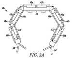
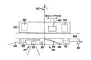
図2Aと図3は、一実施形態に係る油圧システムを備えるロボット装置40を示す。ロボット装置40は、6つのピストンアセンブリ42a,42b,42c,42d,42e,42fを有する。ピストンアセンブリ42a,42bはロボット装置40の本体44内に配置され、ロボットアーム46a,46bの第1リンク48a,48bを作動させる。ピストンアセンブリ42c,42dは第1リンク48a,48b内に配置され、第2リンク50a,50bを作動させる。またピストンアセンブリ42e,42fは第2リンク50a,50b内に配置され、操作要素52,54を作動させる。 2A and 3 show a robot apparatus 40 including a hydraulic system according to an embodiment. The robot apparatus 40 includes six
あるいはロボット装置40の数は、1個から、作動要素としてロボット装置に統合可能なピストンアセンブリの数までであってもよい。一実施形態によると、ピストンにはそれぞれ自由度がある。 Alternatively, the number of robotic devices 40 may be from one to the number of piston assemblies that can be integrated into the robotic device as actuating elements. According to one embodiment, each piston has a degree of freedom.
図2Bに示す一実施形態によると、油圧システム56の外部要素は、ロボット装置への高圧供給ライン57aを提供し、ロボット装置からの低圧返還ライン57bを収容する。
他の実施形態において、ロボット装置は、バルブシステムまたはマスタバルブシステム58を有する。バルブシステムまたはマスタバルブシステム58は、作動油の流れを制御し、適宜流体をピストンアセンブリ(たとえば図2Aと図3に示すアセンブリ)に向ける。According to one embodiment shown in FIG. 2B, the external elements of the
In other embodiments, the robotic device has a valve system or
図4は、一実施形態に係る、リンク62をロボット本体64に接続するロボット装置ジョイント部60を示す。ロボット本体64はピストンアセンブリ66を有する。ピストンアセンブリ66において、ピストン68はピン70に接続され、ピン70は接続点72においてリンク62に接続されている。一実装例において、リンク62は第1リンク62であり、この場合、ロボット装置ジョイント部60は、ロボット本体64と第1リンク62の間のジョイント部60である(「ショルダジョイント」とも言う)。 FIG. 4 illustrates a robotic device joint 60 that connects the
図5は、一実施形態に係る第1リンク82を第2リンク84に接続するロボット装置ジョイント部80を示す。第1リンク82はピストンアセンブリ86を有する。ピストンアセンブリ86において、ピストン88はピン90に接続され、更にピン90は接続点92において第2リンク84に接続されている。一実装例において、2つのリンク82,84の間のジョイント部80は、「エルボジョイント」と言う。 FIG. 5 shows a robot apparatus joint 80 that connects the
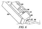
図6は、一実施形態に係る、ロボットアーム102に連結される操作要素100を示す。ロボットアーム102はピストンアセンブリ104を有する。ピストンアセンブリ104において、ピストン106は操作要素100の一部に接続されている。具体的には、ピストン106は接続点110においてスライディング要素108に連結されている。ピストンアセンブリ104の生成する力がスライディング要素110に対して変換され、スライディング要素110をロボットアーム102において前後にスライドさせるように、スライディング要素110はロボットアーム102において摺動自在に配置される。 FIG. 6 illustrates the
スライディング要素110の前後へのスライディング動作によって、ロボットアーム102に対し操作要素100が伸展および後退するように、操作要素100はジョイント部112においてスライディング要素110に連結される。これによって、ロボットアーム102までの操作要素100の到達距離、および操作要素100が動作する処置空間の長短が可能になる。別の言い方をすれば、一実施形態によると、スライディング要素110およびロボットアーム102のこのスライド可能な連結部は、ロボットアーム102の「手首部」であると考えられる。スライディング要素110の前後へのスライディング動作は、ロボットアーム102の残りの部分に対して、「手首部」を長短するように動作する。 The
一実施形態において、スライディング要素108に配置されたアクチュエータ(図示なし)は、操作要素100を作動させる。たとえば操作要素100が1組のグラスパ100である図6に示す実施形態において、アクチュエータは、グラスパを開位置と閉位置の間で移動するように作動させる。 In one embodiment, an actuator (not shown) disposed on the sliding
空気圧システムは、図2A、図2B、および図3〜図6に示す実施形態および要素に組込可能であること、また一般に上記の方法によって動作可能であることを理解されたい。他の種類の流体作動システムも、一般にこれらの実施形態において同様の方法で実施可能であることを理解されたい。 It should be understood that the pneumatic system can be incorporated into the embodiments and elements shown in FIGS. 2A, 2B, and FIGS. 3-6, and can generally operate in the manner described above. It should be understood that other types of fluid actuation systems can generally be implemented in a similar manner in these embodiments.
一実装例によると、流体作動システム(たとえば本明細書に開示の各種システム)を備える装置は、装置に付随するコストを削減可能にする。すなわち装置に関連するシステムの要素は、(高価な搭載モータを備える装置に比べて)低価格で装置への統合が可能である。一方、一層高価な要素をシステムの外部要素に組込むことができ、長期間再使用できる。他の実施形態において、流体作動システムを装置に使用することによって、内部モー
タに比べて増強した力および/またはスピードを提供できる。According to one implementation, a device with a fluid actuation system (eg, various systems disclosed herein) can reduce the costs associated with the device. That is, the system elements associated with the device can be integrated into the device at a lower cost (as compared to a device with an expensive on-board motor). On the other hand, more expensive elements can be incorporated into the external elements of the system and can be reused for a long time. In other embodiments, a fluid actuation system can be used in the device to provide increased force and / or speed compared to an internal motor.
更に他の実施形態において、装置は、少なくとも1本のピストンと少なくとも1つのモータを備える「ハイブリッド」であり、装置の構成と非常に緻密な動作を実現する能力とに一層柔軟性を与える。たとえば緻密な動作とは、手首部の動作(組織解剖は細心の注意を要するため、非常に緻密な制御が必要な回転または伸張など)を含み得る。このような実施形態において、流体作動ピストンアセンブリは、一層高い電力を要する粗い作動および/または即座の作動(たとえばショルダジョイントおよび/またはエルボジョイントの作動)を目的として使用できる。一方、モータアセンブリは、緻密で一層ゆっくりした作動(たとえば解剖などの緻密な作業のための手首部または操作要素の作動)を目的として使用できる。このようにショルダジョイントおよびエルボジョイントの流体作動アセンブリは、一層高い電力を必要とする引張動作または切断動作に継続して使用できる。 In yet another embodiment, the device is a “hybrid” with at least one piston and at least one motor, giving more flexibility to the configuration of the device and the ability to achieve very precise operation. For example, precise movements can include wrist movements (such as rotation or extension that requires very fine control because tissue dissection requires close attention). In such embodiments, the fluid-actuated piston assembly can be used for coarse and / or immediate actuation that requires higher power (eg, shoulder and / or elbow joint actuation). On the other hand, the motor assembly can be used for precise and slower operation (for example, activation of a wrist or operating element for precise work such as dissection). Thus, the fluid actuation assembly of the shoulder joint and elbow joint can continue to be used for tensioning or cutting operations that require higher power.
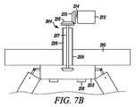
上記の流体作動システムに加えて、本明細書において開示または具体化される各種医療装置で実施可能な他の作動システムとして、駆動システムがある。駆動システムの一実装例を図7Aに示す。図7Aは、駆動システム200によって機械的に動力供給または作動が行われるロボット装置202を示す。駆動システム200はロボット装置202に連結した駆動要素204を備え、ロボット装置202に機械力を供給する。 In addition to the fluid actuation systems described above, drive systems are other actuation systems that can be implemented with the various medical devices disclosed or embodied herein. One implementation example of the drive system is shown in FIG. 7A. FIG. 7A shows a
図7Bに示す一実施形態において、駆動要素204は、互いにおよび作動要素212(一実装例によると、駆動モータ212であってもよい)に接続され、最終的にロボット装置202に接続される一連の軸およびカプラを含む。具体的には、駆動要素204は、駆動シャフト214と、第1連結要素215と、第2連結要素216と、接続シャフト217と、第3連結要素218とを含む。一実施形態によると、第1連結要素215、第2連結要素216、および第3連結要素218は互いに連結可能なギアである。動作時、図7Bに示す作動要素212は、駆動シャフト214を作動させることによって駆動要素204に動力を供給する。駆動シャフト214の回転は、第1連結可能ギア215および第2連結可能ギア216によって、接続シャフト217の回転に動力を供給する。その後、動力は第3ギア218によって医療装置202に伝達される。 In one embodiment shown in FIG. 7B, the
あるいは駆動要素204は、ロボット装置202に回転動力を伝達可能なフレキシブルロッドである。他の実施形態において、駆動要素204は、ロボット装置202に動力を伝達可能な既知の駆動要素である。 Alternatively, the
図7Aと図7Bに示すように、この特定の実施形態は、患者の体内に配置されたロボット装置202に接続した針、ポート、または他の種類の挿入要素206の内部に配置される駆動要素204に関する。あるいは挿入要素206は、患者の体内のロボット装置202へのアクセスまたは接続を与える開口部またはチャネルである。具体的には、図7に示す実施形態において、挿入要素206は、患者の切開口208(たとえば腹壁210の切開部208)から挿入されるトロカール状のポート206である。その後、駆動要素204はポート206内に配置され、患者の体腔に配置されたロボット装置202に接続される。 As shown in FIGS. 7A and 7B, this particular embodiment provides a drive element disposed within a needle, port, or other type of
上記のとおり、駆動要素204は、ロボット装置202に回転作動を与える回転シャフト204であってもよい。一実装例において、回転シャフト204は、ジョイント部および他の作動要素を作動させるために該作動をピストンアセンブリまたは他の並進アセンブリに伝達する一連のクラッチ(図示なし)を有する。小型のクラッチは、フロリダ州マイアミレイクスのSmall Parts社から市販されている一般の部品である。一実施形態において、クラッチは油圧で動作する。あるいはクラッチは電気的にまたは他の既知の方法で動作する。 As described above, the
他の代替実装例において、駆動要素204には1つ以上の伸張可能な搭載(onboard)スプリングが巻かれている。このスプリングは、クラッチシステムによって、ロボット装置のエンドエフェクタまたは他の駆動可能要素/被駆動要素に動力を供給する。 In other alternative implementations, the
あるいは回転シャフト204はフレキシブルロッド204である。本実施形態において、挿入要素206は直線的でなくてもよい。一例において、挿入要素206は患者の食道に挿入され、胃壁の切開口から腹腔に挿入される。内部のフレキシブルロッド204は、挿入要素206内に配置され、ロボット装置202に連結される。この例において、フレキシブルロッド204は、ロボット装置202に回転作動を与えるように回転する。 Alternatively, the
任意の流体作動システムまたは駆動系作動システム(たとえば上記のシステム)と共に使用可能な1つの要素は、可逆的にロック可能なチューブである。本明細書において、「可逆的にロック可能なチューブ」は、フレキシブルな構成とロックされた構成(「ロックされた」とは、ある程度の剛性を包含する)の間で切替、調節、または変更が可能な管状部材を意味する。本明細書において、フレキシブルな構成と剛性のある構成の間の調節も、「可逆的にロック可能な」特徴と言う。本明細書において用いられる「チューブ」という語は、医療治療装置および/または患者の体内に配置される装置への接続のために、患者の様々な体腔にアクセスする管状またはホース状の部材を包含する。 One element that can be used with any fluid actuation system or driveline actuation system (eg, the system described above) is a reversibly lockable tube. As used herein, a “reversibly lockable tube” is a switchable, adjustable, or changed between a flexible configuration and a locked configuration (“locked” includes some stiffness). Means a possible tubular member. As used herein, adjustment between a flexible configuration and a rigid configuration is also referred to as a “reversibly lockable” feature. As used herein, the term “tube” includes tubular or hose-like members that access various body cavities of a patient for connection to a medical treatment device and / or a device disposed within the patient's body. To do.
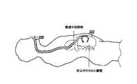
図8は、患者の目的とする体腔に配置されるロボット装置222に連結される可逆的にロック可能なチューブ220の一実施形態を示す。上記のように、チューブ220の一実施形態は、フレキシブルな構成と剛性のある構成(または「ロックされた構成」)との間で調節可能である。使用時、上記のような油圧または空気圧の作動システムは、患者の体外に配置される要素に接続する他の要素と同様に、患者の体内に配置されるロボット装置をチューブ220内に配置可能である。具体的には、チューブ220はフレキシブルな構成に保持され、チューブ220は患者の体内の開口部から(たとえば図8に示すように患者の口および食道から)配置される。一度配置されると、チューブ220はロボット装置222の動作時にはロックされた構成に調節できる。本明細書に開示の各種ロック可能なチューブの実施形態に係る動作については、以下に詳細に説明する。 FIG. 8 illustrates one embodiment of a reversibly
図10と図11は、複数のモジュラチューブ要素(本明細書において「リンク」とも言う)から成る、一実施形態に係る可逆的にロック可能なチューブ240を示す。
モジュラチューブ要素260(たとえば図10と図11に示すチューブ240に使用されるモジュラチューブ要素)の一例を、図9Aと図9Bに示す。図9Aは雄端262(または「突起部」)を示し、図9Bは雌端264を示す。図9Aに示すように、雄端262は凸状突起である。あるいは雄端262は、雌端264に一致するどのような突起形状であってもよい。図9Bに示すように、雌端264は凹面の構成である。あるいは雌端264は、雄端262に一致するどのような形状または構成であってもよい。10 and 11 show a reversibly
An example of a modular tube element 260 (eg, a modular tube element used in the
図9Aと図9Bに示すように、各モジュラチューブ要素260は、モジュラチューブ要素260によって定義される少なくとも1つの孔268(本明細書において「チャネル」とも言う)を有する。図に示すように、モジュラチューブ要素260は、3つのチャネル268,270,272を有する。一実施形態によると、チャネル268,270,272は、たとえば図10と図11に示すように、可逆的にロック可能なチューブ240内に挿入または配置されるケーブルまたはチューブの経路を収容する(および/または可能にする)ように構成されている。一実装例において、中央のチャネル268は、図10と図11に最もよく示されるように、剛性ケーブル242を収容するように構成されている。剛性ケーブル242は、チューブ240を剛性のある構成または位相に変換または調節するのに使用される。チャネル270,272など追加のチャネルも、電気的な接続要素、
油圧式または空気圧式のチューブ、または目的とする体腔への挿入、または目的とする体腔に配置されるロボット装置への接続を必要とする他の伸張部材を収容するように構成されている。As shown in FIGS. 9A and 9B, each
It is configured to accommodate a hydraulic or pneumatic tube or other extension member that requires insertion into a target body cavity or connection to a robotic device disposed in the target body cavity.
図10、図11、および図12に最もよく示される一実施形態によると、剛性ケーブル242は以下のように動作して、チューブ240をフレキシブルな構成から剛性のある構成に調節または変換する。図11に示すフレキシブルな状態において剛性ケーブル242は緩むため、モジュラチューブ要素246は互いに付勢されず、硬固な構成にはならない。一実施形態によると、各モジュラチューブ要素246はフレキシブルな状態において、隣接するモジュラチューブ要素246に対して約20度移動できる。チューブ240をフレキシブルな状態から堅固な状態に調節または変形させることが望ましい場合、剛性ケーブル242は、自身の基端248においてチューブ240から離れる方向に引かれる(または付勢される)。これによってケーブル端244は末端のモジュール要素250に接触し、チューブ240の他の要素に向かって該モジュール要素250を付勢し始める。最終的にはモジュラチューブ要素246は付勢されて堅固な構成になり、各モジュラチューブ要素246は堅固に積層されるか、あるいは他のモジュラチューブ要素246に密着する。その結果、チューブ240は堅固な構成になる。 According to one embodiment best shown in FIGS. 10, 11, and 12, the
チューブ(たとえばチューブ220またはチューブ240)は使用時に、患者の体内にロボット装置を挿入するために、フレキシブルな構成または状態にされる。該装置がユーザの所望どおりに(図8または図13に示すロボット装置222およびチューブ220の位置)に配置されると、チューブは堅固な構成または位相に調節または変換される。剛性によって、幾何学的または物理的な形状の維持、および/または患者に対するチューブの配置が助けられる。またロボット装置と油圧システム、空気圧システム、または駆動システムの外部要素との間の接続によって与えられる油圧もしくは空気圧の力、または物理的力の矯正力に耐性を有することができる。これについては当技術分野において既知であり、上記から明白である。このようにチューブは使用時に、ロボット装置の安定性の維持を助けることができる。あるいは一般に医療装置の操作または医療治療に利益をもたらすため、剛性によって、チューブの幾何学的または物理的な形状の維持および/または配置が助けられる。 The tube (eg,
上記の流体作動システムおよび駆動システムの実施形態に加えて、本明細書に開示または記載の医療装置への組込または使用が可能な他の作動要素として、モータレス作動システムまたはモータレス作動要素がある。 In addition to the fluid actuation system and drive system embodiments described above, other actuation elements that can be incorporated or used in the medical devices disclosed or described herein include motorless actuation systems or motorless actuation elements.
図14Aと図14Bは、モータレス作動要素の一実施形態を示す。具体的には、図14Aと図14Bは、一実施形態に係るロボットカメラ装置310を示す。ロボットカメラ装置310は患者の腹腔内に配置され、磁気ハンドル312が患者の体外の或る位置に配置されている。磁気ハンドル312は、腹腔内のロボットカメラ装置310を磁力によって腹膜(腹壁)に保持するように動作する。このモータレス作動要素の実施形態は、上記の同時係属出願に開示される実施形態に組込可能であることを理解されたい。 14A and 14B show one embodiment of a motorless actuating element. Specifically, FIG. 14A and FIG. 14B show a
図14Aと図14Bに示す実装例において、ロボットカメラ装置310は円筒状であり、イメージング要素314、照明要素316、ロボット装置の各端にある体内磁石318、および有線接続要素320(本明細書において「ワイヤテザー」とも言う)を備える。ロボットカメラ装置310が体腔壁に付勢および保持されるように、体内磁石318は、磁気ハンドル312上の外部磁石322に磁気的に結合可能である。一実施形態において、関心のある体腔または目的とするエリアの映像をキャプチャするようなイメージング要素314の配置を保証するように、体内磁石318は構成される。 In the implementation shown in FIGS. 14A and 14B, the
ロボットカメラ装置310の体内磁石318、および磁気ハンドル312の外部磁石322は、任意の構成に配置可能であること、また本明細書に援用される米国特許出願第11/766,720号明細書、2007年6月21日出願、「Magnetically
Coupleable Surgical Robotic Devices and
Related Methods」;および米国特許出願第11/766,683号明細書、2007年6月21日出願、「Magnetically Coupleable
Robotic Devices and Related Methods」に開示されるように、任意の数の磁石を備えてもよいことを理解されたい。The
Coupleable Surgical Robotic Devices and
Related Methods "; and U.S. Patent Application No. 11 / 766,683, filed June 21, 2007," Magnetically Coupleable ".
It should be understood that any number of magnets may be provided, as disclosed in “Robotic Devices and Related Methods”.
一実施形態において、磁気ハンドル312(本明細書において「外部磁石」とも言う)は、ハンドル形状であることを理解されたい。あるいは本明細書に記載のとおり磁気要素を用いてロボット装置の配置、操作、または制御を行えるように、磁気ハンドル312は、任意のロボット装置と磁気的に結合可能な磁気成分を包含することが意図される。 It should be understood that in one embodiment, the magnetic handle 312 (also referred to herein as an “external magnet”) is handle shaped. Alternatively, the
援用される上記特許文献に記載の一実施形態において、イメージング要素のチルト機能が可能となるように、磁気ハンドル312は矢印342で示すように回転可能である。またロボット装置は、矢印344で示すイメージング要素の回転によってパンニング(panning)機能を提供できる(以下に詳述する)。 In one embodiment described in the above-referenced patent document, the
使用時、ロボットカメラ装置310は、体外の磁気ハンドル312を移動させることによって、患者の体内の所望位置に移動可能である。あるいはロボットカメラ装置310は、援用される上記特許文献に記載の方法で体外に配置された磁気ハンドル312によって少なくとも部分的に、患者の体内のどの場所においても配置、操作、または制御が可能である。 In use, the
一実装例によると、図14Aと図14Bに示すロボットカメラ装置310は2つの部分:内側部分330と外側部分332を有する。これは図14Bに最もよく示されている。一実施形態によると、内側部分330は円筒形状の内側本体330であり、外側部分332は、内側本体330上に回転可能に配置されるように構成された外スリーブ332である。このような実施形態において、イメージング要素314とレンズ315は、外スリーブ332に対して内側本体330を回転させることによってパンニング可能であり、矢印344で示すような方法でレンズ315を回転させる。一実装例において、内側本体330は、1組のベアリング(図示なし)で外スリーブ332に連結される。 According to one implementation, the
一実装例において、外側部分332に対して内側部分330を回転させる作動要素334は、モータレス作動要素である。すなわち作動要素はモータではなく、どのような種類のモータ要素でもない。たとえば図14Aと図14Bに示す作動要素334は、レース336とボール338を含む。本実施形態において、患者の外部の外部磁石340は、レース336に沿ってボール338を付勢するのに用いられる。このような実施形態において、外部磁石340は、本明細書において図14Aに示すように記載された磁気ハンドル312に連結可能である。一実施形態において、レース336は螺旋形であり、ボール338はスチールである。レースとボールの実装例において、ボール338がレースチャネル336に沿って移動すると、内側本体330は外スリーブ332に対して回転する。他の実施形態において、ボール338は磁気であり、レース336に沿って移動する。 In one implementation, the
図15は、作動要素352が複数の体内磁石354を備えるモータレス作動要素の代替実施形態を示す。複数の体内磁石354は、ロボット装置350内(または上)に配置されている。本実施形態において、体内磁石354は内部シリンダ(図示なし)に螺旋パターン状に配置される。すなわち外部磁石356が並進すると、外部磁石356に隣接する内部本体磁石354が外部磁石356に向かって付勢されるにしたがい、内部本体は外ス
リーブ358に対して回転する。他の実施形態において、磁気ハンドル360に沿った有効磁場を移動させるために、磁気ハンドル360の一連の電磁石を作動させることができる。FIG. 15 shows an alternative embodiment of a motorless actuation element in which the
他の代替実施形態においては、他の手段によって、ボールをレースに沿って付勢できる。たとえばロボット装置は、自身に有線接続され、外部ハンドルにも接続されたケーブルまたはワイヤを備えてもよい。このケーブルの作動によってボールはレースに沿って付勢され、外スリーブに対して内部本体のパンニング動作を生じさせる。一実施形態において、ケーブルの作動によってボールがレースに沿って付勢されるように、何らかの方法でケーブルはボールに取付けられるか、あるいは操作可能に連結される。 In other alternative embodiments, the ball can be biased along the race by other means. For example, the robotic device may include a cable or wire that is wired to itself and also connected to an external handle. Actuation of this cable biases the ball along the race, causing the inner body to pan against the outer sleeve. In one embodiment, the cable is attached or operably coupled to the ball in some manner such that actuation of the cable biases the ball along the race.
他の代替例において、モータレス作動要素はボールとレースを備えず、代わりにドラムを備える。本実施形態において、上記のようなケーブルの作動によってドラムが付勢され、回転するように、ケーブルはドラムに取付けられる。このようなドラムの回転によって、医療装置の回転作動が生じる。あるいは並進動作を回転動作にするという既知の方法を用いてもよい。また本明細書に記載される、または参照として援用される医療装置には、既知のモータレス作動要素が組込可能であることを理解されたい。 In another alternative, the motorless actuating element does not comprise a ball and race, but instead comprises a drum. In this embodiment, the cable is attached to the drum so that the drum is biased and rotated by the operation of the cable as described above. Such rotation of the drum causes rotation of the medical device. Alternatively, a known method in which the translation operation is a rotation operation may be used. It should also be understood that known motorless actuating elements can be incorporated into the medical devices described herein or incorporated by reference.
本明細書には、様々な種類の医療装置に組込可能な各種メカニカルアームの実施形態が提供される。本明細書に開示の医療装置のアーム構成は、2つの自由度を備える各種アームの実施形態を提供する。自由度とは、(1)軸方向の動作(アームの縦軸におけるアームの一部分の伸長および格納)と;(2)アームの軸を中心とする回転動作である。これらの構成は、従来技術の構成よりも比較的小型またはコンパクトな構成を維持しつつ、上記の2つの自由度を提供する。 Provided herein are various mechanical arm embodiments that can be incorporated into various types of medical devices. The medical device arm configurations disclosed herein provide various arm embodiments with two degrees of freedom. The degrees of freedom are (1) axial movement (extension and storage of a part of the arm on the longitudinal axis of the arm); and (2) rotational movement about the axis of the arm. These configurations provide the above two degrees of freedom while maintaining a relatively small or more compact configuration than prior art configurations.
本明細書に開示のアームの実施形態は、コンパクトまたは一層小型であることが望ましい装置(たとえば患者の体内で処置を行える装置)など、あらゆる種類の医療装置に利用可能であることを理解されたい。たとえばアームの実施形態は、生体内ロボット装置(たとえば患者の内腔壁上(または付近)に配置可能なロボット装置、可動ロボット装置、またはロボット可視化・制御システム)など、様々なロボット医療装置に組込可能である。本明細書に用いられる「生体内装置」とは、少なくとも部分的にユーザが配置、操作、または制御を行うことができ、患者の体腔内に配置される装置である。たとえば患者の体腔壁に接触または隣接して配置される装置、および(原動力となる外部源なく)内部で作動される装置である。本明細書において、「ロボット」および「ロボット装置」という語は、コマンドに応じて、または自動的にタスク(すなわち作業)を実行可能な装置を言う。またアームの実施形態は、外的に作動される様々なロボット医療装置システム(たとえばApollo Endosurgery社、Hansen Medical社、Intuitive Surgical社から入手可能な装置)、および他の同様のシステムに組込可能である。 It should be understood that the arm embodiments disclosed herein can be used with any type of medical device, such as devices that are desired to be compact or more compact (eg, devices capable of performing treatment within a patient's body). . For example, arm embodiments are incorporated into various robotic medical devices, such as in-vivo robotic devices (eg, robotic devices that can be placed on (or near) the lumen wall of a patient, mobile robotic devices, or robotic visualization and control systems). Can be included. As used herein, an “in vivo device” is a device that can be placed, manipulated, or controlled at least in part by a user and placed in a body cavity of a patient. For example, devices placed in contact with or adjacent to a patient's body cavity wall and devices that are operated internally (without a driving external source). In this specification, the terms “robot” and “robot device” refer to a device capable of executing a task (ie, work) in response to a command or automatically. The arm embodiments can also be incorporated into various externally actuated robotic medical device systems (eg, devices available from Apollo Endosurgery, Hansen Medical, Intuitous Surgical), and other similar systems. is there.
図16に示す一実施形態によると、アームの一実施形態は、図に示す生体内医療装置402に組込まれる。生体内医療装置402は、本明細書に記載の実施形態によって構成可能な2つのロボットアーム404,406を有する。 According to one embodiment shown in FIG. 16, one embodiment of an arm is incorporated into the in-vivo
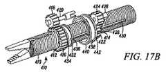
図17Aと図17Bは、一実施形態に係る装置アーム410を示す。装置アーム410は2つのギア:(1)装置アーム410の伸長および格納を行う遠位ギア412と;(2)装置アーム410に回転を与える近位ギア414とを有する。 17A and 17B show a
遠位ギア412は、外表面に遠位ギア歯416を有し、内表面(図示なし)にはネジ山が形成されている。遠位ギア歯416は、アクチュエータ(図示なし)に連結した駆動ギ
ア420のギア歯418に一致または連結する。一実施形態において、アクチュエータは永久磁石直流(「PMDC」)モータであり、遠位ギア412はアクチュエータによって駆動される。The
遠位ギア412の内表面のネジ山は、装置アーム410の外表面のネジ山413に一致または連結する。すなわち遠位ギア412がアクチュエータによって駆動されると遠位ギア412が回転し、遠位ギア412の内表面のネジ山と装置アーム410のネジ山413とが連結するため、装置アーム410は遠位ギア412の回転方向に依存して伸長または格納される。 The thread on the inner surface of the
近位ギア414は、外表面に近位ギア歯422を有する。近位ギア歯422は、アクチュエータ(図示なし)に連結した駆動ギア426のギア歯424に一致または連結する。近位ギア414は、近位ギア414内に配置されるピン428を有する。ピン428は近位ギア414内に伸長し、更に装置アーム410のスロット430内に伸長する。したがって、近位ギア414が回転すると、ピン428によって装置アーム410も回転する。
遠位ギア412と近位ギア414は、ベアリング面においてインタフェース連結または相互作用を行う。具体的には、遠位ギア412は、2つの遠位ブッシング434,436を備える遠位ベアリング面432(図17Bに最もよく示される)を有する。遠位ブッシング434,436は、遠位ベアリング面432の外表面に配置または配置される。同様に、近位ギア414は、2つの近位ブッシング440,442を備える近位ベアリング面438を有する。遠位ベアリング面432の直径は、近位ベアリング面438の直径よりも小さい。また遠位ベアリング面432は、近位ベアリング面438の内表面が2つの遠位ブッシング434,436に接触するように、近位ベアリング面438内に配置される。このように遠位ベアリング面432,438は互いに接触し合い、2つの遠位ブッシング434,436において互いに回転する。また近位ベアリング面438の外表面に配置された2つの近位ブッシング440,442は、一般に外部ギアハウジングまたは他の種類のハウジング(図示なし)に接触する。 The
代替実施形態において、図17Aと図17Bに示すギアの対418,412および424,422は、円形の車輪の対に置換えられてもよい。各車輪は対のうちの他方の車輪に接触するように構成される。このような実施形態において、各車輪は、車輪同士が接触して2つの車輪間で回転エネルギーを伝達するときに十分な摩擦をもたらす被覆要素または他の表面要素を有する。一実施形態によると、被覆は薄いゴム製被覆である。あるいは被覆または表面は、回転エネルギーの伝達を可能にするだけの摩擦をもたらす既知の被覆または表面であってもよい。この摩擦駆動システムにおいてはギア歯を無くしているため、ギア要素の大きさを縮小できる。 In an alternative embodiment, the gear pairs 418, 412 and 424, 422 shown in FIGS. 17A and 17B may be replaced with circular wheel pairs. Each wheel is configured to contact the other wheel of the pair. In such an embodiment, each wheel has a covering element or other surface element that provides sufficient friction when the wheels are in contact to transfer rotational energy between the two wheels. According to one embodiment, the coating is a thin rubber coating. Alternatively, the coating or surface may be a known coating or surface that provides friction sufficient to allow transmission of rotational energy. In this friction drive system, since the gear teeth are eliminated, the size of the gear element can be reduced.
他の実施形態において、ギアは、アームの作動に用いられる一連のケーブルおよびドラムに置換えられてもよい。このプーリ(すなわち滑車)システムの実施形態において、ケーブルを駆動するアクチュエータは、ロボットの別の部分に配置されてもよく、一連のドラムはアームに配置される。ケーブルは、ドラムをアクチュエータ(たとえばモータ)に接続する。本実施形態は、アームのエンドエフェクタに対して十分な作動力とスピードを与えつつ、アクチュエータ、ドラム、およびアーム要素を様々な異なる姿勢に構成可能にする。 In other embodiments, the gear may be replaced with a series of cables and drums used to actuate the arm. In this pulley (ie, pulley) system embodiment, the actuator that drives the cable may be located in another part of the robot and the series of drums is located in the arm. A cable connects the drum to an actuator (eg, a motor). This embodiment allows the actuator, drum, and arm elements to be configured in a variety of different postures while providing sufficient actuation force and speed for the arm end effector.
図18は、代替実施形態に係る他の装置アーム450を示す。装置アーム450は、遠位ギア452と近位ギア454を有する。
遠位ギア452は遠位ギア歯456を有し、内表面(図示なし)にはネジ山が形成されている。遠位ギア歯456は、アクチュエータ(図示なし)に連結した駆動ギア460の
ギア歯458に一致または連結される。上記の実施形態と同様に、遠位ギア452の内表面のネジ山は、装置アーム450の外表面のネジ山453に一致または連結する。すなわち遠位ギア452がアクチュエータによって駆動されると遠位ギア452が回転し、遠位ギア452の内表面のネジ山と装置アーム450のネジ山453とが連結するため、装置アーム450は遠位ギア452の回転方向に依存して伸長または格納される。FIG. 18 shows another
近位ギア454は、外表面に近位ギア歯462を有する。近位ギア歯462は、アクチュエータ(図示なし)に連結した駆動ギア466のギア歯464に一致または連結する。近位ギア454は、近位ギア454内に配置されるピン468を有する。ピン468は近位ギア454に伸長し、更に装置アーム450のスロット470内に伸長する。したがって、近位ギア454が回転すると、ピン468によって装置アーム450も回転する。
図18に示す本実施形態のベアリング面は、上記の実施形態のベアリング面とは異なる。すなわち遠位ギア452は、近位ギア454の近位ベアリング面474に隣接または接触する遠位ベアリング面472を有する。したがって、遠位ギア452と近位ギア454は、ベアリング面472,474において互いに回転する。また2つのベアリング面472,474は、外部ギアハウジング内において通常接触または配置される。 The bearing surface of this embodiment shown in FIG. 18 is different from the bearing surface of the above embodiment. That is, the
本発明は好ましい実施形態について記載しているが、本発明の精神および範囲から逸脱することなく、形式および詳細において変更がなされ得ることを当業者に理解されたい。
本明細書に開示の治療装置で使用可能なエンドエフェクタまたは操作要素として、ウィンチシステムがある。一般に、本明細書に記載の装置またはシステムは、患者の体内(たとえば体腔)に挿入または配置されるように構成される。あるいは本明細書に開示のウィンチシステムおよび装置は、医療装置または治療装置で使用可能である。Although the present invention has been described with reference to preferred embodiments, workers skilled in the art will recognize that changes may be made in form and detail without departing from the spirit and scope of the invention.
An end effector or operating element that can be used with the treatment device disclosed herein is a winch system. In general, the devices or systems described herein are configured to be inserted or placed into a patient's body (eg, a body cavity). Alternatively, the winch systems and devices disclosed herein can be used in medical or therapeutic devices.
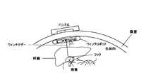
図19Aと図19Bは、ウィンチ要素を備える医療装置の一実施形態を示す。医療装置510は、患者の腔内に配置可能な生体内ロボット装置510である。また医療装置510は、患者の体外の或る位置に配置可能な磁気ハンドル512を有する。本実施形態において、磁気ハンドル512は腹腔内において磁力によって腹膜(腹壁)に医療装置510を保持するように動作する。あるいは医療装置510を腹壁に保持するための既知の方法または要素を使用してもよい。たとえば一実施形態において、ロボット510はフックまたはクランプを使用して、壁に保持されてもよい。他の代替例において、本明細書に開示のウィンチシステムは、既知の医療装置(たとえばこれに限定されないが、アームまたは車輪を備える生体内装置)で使用されてもよい。 19A and 19B illustrate one embodiment of a medical device that includes a winch element. The
図19Aと図19Bに示す実装例において、医療装置510は、ウィンチ要素524と、ウィンチ要素524を作動させるモータ530とを有する。本実施形態において、ウィンチ要素524はドラム526とウィンチテザー528を含む。ドラム526はウィンチテザー528を巻いたり解いたりするように作動する。 In the implementation shown in FIGS. 19A and 19B, the
図に示す実施形態によると、医療装置510は、磁気ハンドル512上の外部磁石532に磁気的に結合可能な体内磁石520を備える。これによって、医療装置510は体腔壁に対して付勢および保持される。医療装置510、磁気ハンドル512および磁石520,532は、上記の引用によって援用される米国特許出願第11/766,720号明細書、2007年6月21日出願、「Magnetically Coupleable
Robotic Devices and Related Methods」に記載の方法と同様に構成および/または操作が可能である。一実施形態において、体内磁石520は以下のように構成されることを理解されたい。すなわちウィンチ要素524を固定すべく関心のある体腔または目的とするエリアの映像をキャプチャするようにイメージング要素516は配置されることが保証され;並びに、ウィンチ要素524が所望どおりに
、および本明細書に記載どおりに操作可能となるように、医療装置510を安定した固定位置に保持するだけの強い磁気結合を与えるように構成される。According to the illustrated embodiment, the
It can be configured and / or operated in a manner similar to that described in “Robotic Devices and Related Methods”. It should be understood that in one embodiment, the
図19Aと図19Bに示す実施形態によると、作動要素530は、ドラム526を回転させる力を与えるモータ530である。本実施形態において、モータ530は、静止している太陽歯車の周囲を旋回する遊星ギアを回転させる6mmの整流子モータであり、ドラム526を本体514内で回転させる。あるいはクラッチ(図示なし)は、(1)本体514の軸に沿ったカメラ516の動作のパンニングと;(2)単一モータを使用するウィンチ作動との両方を提供するために使用可能である。他の代替例において、外部の駆動系は、ウィンチ要素524を作動させるのに使用可能である。医療装置で使用可能な既知の作動要素が、本明細書に記載のウィンチ要素またはシステムで使用可能であることを理解されたい。 According to the embodiment shown in FIGS. 19A and 19B, the
一実施形態において、ウィンチテザー528は縫合材料からなる。他の実施形態において、ウィンチテザー528は金属ケーブルである。あるいは医療ウィンチテザーに用いられる既知の材料を使用してもよい。 In one embodiment,
一実施形態において、様々な操作要素またはエンドエフェクタが、ウィンチテザーの端部に取付けられてもよい。一実施形態において、図19Aと図19Bの実施形態に示すように、ウィンチテザー528の端部はフック536に取付けられている。図20はこのようなフックの使用を示す。あるいはテザーのエンドエフェクタ(「操作要素」とも言う)は、クランプかループであってもよい。他の代替例において、既知の操作要素(たとえば組織に取付けられる既知の要素)が使用されてもよい。 In one embodiment, various operating elements or end effectors may be attached to the end of the winch tether. In one embodiment, the end of
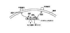
他の実施形態において、操作要素は、図21に示す第2ハンドル542によって腹壁に保持可能な体内磁石540であってもよい。他の実施形態において、医療装置は、図22に示す体内の2箇所に取付けられる磁石操作要素552を含む2つのウィンチ要素550を備えてもよい。このような医療装置は、2つの別個のドラムおよびモータ、または代わりに単一のモータおよびドラムを備えてもよい。 In another embodiment, the operating element may be a
ウィンチ要素およびシステムは、様々な治療作業を行うのに使用可能である。一実施形態において、図20に例を示すように、ウィンチ要素を備える装置は、臓器(たとえば胆嚢)を引込むのに使用されてもよい。他の実施形態において、ウィンチ要素と磁石操作要素を備える医療装置は、図21に示すように、非常に大きな臓器(たとえば肝臓)を引込む(または移動する)ためのスリングとして使用されてもよい。更に他の実施形態において、医療装置は、図22に示す腹壁に対して、または他の臓器に対して取付けられる2つのウィンチテザーを備える「ガントリークレーン」として使用される。本実施形態において、カメラまたは照明位置を変更するために、医療装置はウィンチテザーに沿って案内される。他の実施形態において、医療装置は、図22に示す医療装置の下方の第3ウィンチフック(またはグラスパ)を用いて、ウィンチテザーに沿って案内されてもよい。これによって、ロボットは2本の第1テザーの線に沿って自身を再び配置可能となり、第3ウィンチを用いて関心のある組織を把持し、引込または他の操作を行うことができる。更に他の実施形態において、ガイドテザーはつり下げられず、臓器上に置かれる。 The winch element and system can be used to perform a variety of therapeutic tasks. In one embodiment, as shown in the example of FIG. 20, a device with a winch element may be used to retract an organ (eg, gallbladder). In other embodiments, a medical device comprising a winch element and a magnet manipulation element may be used as a sling to retract (or move) a very large organ (eg, liver), as shown in FIG. In yet another embodiment, the medical device is used as a “gantry crane” with two winch tethers attached to the abdominal wall shown in FIG. 22 or to other organs. In this embodiment, the medical device is guided along the winch tether to change the camera or illumination position. In other embodiments, the medical device may be guided along the winch tether using a third winch hook (or a grasshopper) below the medical device shown in FIG. This allows the robot to reposition itself along the lines of the two first tethers, grip the tissue of interest using the third winch, and perform retraction or other operations. In still other embodiments, the guide tether is not suspended but placed on the organ.
更に他の代替実施形態において、ウィンチ要素は既知の構成であってもよく、あるいはウィンチに使用される既知の要素から構成されてもよい。また特定の装置の実施形態が本明細書には記載されているが、ウィンチ要素は、患者の体内で使用される既知のロボット装置に組込可能であることを理解されたい。たとえばこのような要素は、本出願明細書に援用される出願に開示される装置に組込可能である。 In still other alternative embodiments, the winch element may be of a known configuration or may be composed of known elements used in the winch. Also, although specific device embodiments are described herein, it should be understood that the winch element can be incorporated into known robotic devices used within the patient's body. For example, such elements can be incorporated into the devices disclosed in the applications incorporated herein.
本明細書に開示の様々な追加の実施形態は、モジュールの機械的・電気的パッケージを備える治療装置に関する。モジュールの機械的・電気的パッケージは、複数の組織サンプルの取得、生理的パラメータのモニタリング、並びに無線のコマンド、制御、およびデータの遠隔測定などの能力を提供するように様々な組合せで用いられてもよい。このモジュール技術は、1つ以上の様々な異なる要素またはシステムの統合が可能なフレキシブルな装置を提供する。 Various additional embodiments disclosed herein relate to a treatment device comprising a modular mechanical and electrical package. The module's mechanical and electrical package is used in various combinations to provide capabilities such as multiple tissue sample acquisition, physiological parameter monitoring, and wireless command, control, and data telemetry Also good. This modular technology provides a flexible device that allows the integration of one or more of a variety of different elements or systems.
現在知られている最小侵襲性の外科技術は、関心のある腹腔および生検組織検査(すなわち生検)の組織を調査する腹腔鏡器具を提供するために、2つまたは3つのポートを要する。本明細書に開示の装置およびモジュール要素の各種実施形態は、任意の医療処置用にただ1つのポートを要するため、患者の外傷が少なくて済む(切開口を2つまたは3つではなく1つにする)。 Currently known minimally invasive surgical techniques require two or three ports to provide a laparoscopic instrument for examining the tissue of the abdominal cavity and biopsy histology (ie, biopsy) of interest. Various embodiments of the devices and modular elements disclosed herein require only one port for any medical procedure, thus reducing patient trauma (one incision instead of two or three incisions). ).
図23Aは、ペイロード領域566を有するモジュール装置の一実装例を示す。ペイロード領域566は、本明細書に記載のセンサ、コントローラ、および生検要素など、複数のモジュール要素のうちの1つを収容するように構成される。本明細書に開示の特定のモジュール要素に加えて、各種実施形態のペイロード領域は、医療治療装置に追加される既知の要素を収容可能であることを理解されたい。 FIG. 23A shows an example implementation of a module device having a
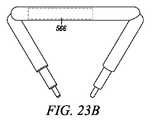
本明細書に開示のモジュール技術は、任意の種類の医療治療装置に組込可能であり、本明細書に詳述するロボット装置に制限されない。特定の装置の実施形態は、本明細書に定義する生体内装置またはロボット装置であってもよい。たとえば患者の体腔内に配置されるように構成された装置、内腔壁に接触または隣接させて配置可能な装置、または関連のシステムであってもよい。たとえば図23Bは、ペイロード領域566を有する異なる装置の実施形態を示す。図23Aに示すロボット装置の実施形態は、車輪を備える可動装置であるが、本明細書に記載の各種モジュール要素は、図23Bに示す装置など他の種類のロボット装置または生体内装置のペイロード領域に、容易に配置または関連付けを行うことができる。あるいはロボット装置に関係しない他の医療装置および用途に用いられてもよい。 The modular technology disclosed herein can be incorporated into any type of medical treatment device and is not limited to the robotic devices detailed herein. Certain device embodiments may be in vivo devices or robotic devices as defined herein. For example, it may be a device configured to be placed in a body cavity of a patient, a device that can be placed in contact with or adjacent to a lumen wall, or an associated system. For example, FIG. 23B shows an embodiment of a different device having a
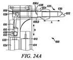
図24A、図24B、および図24Cは、本明細書に開示のロボット装置(たとえば図23Aまたは図23Bに示す)で使用可能な一実施形態に係る生検要素600を示す。この機構600は生検グラスパ632を備える。本実装例において、生検グラスパ632は開孔要素または下顎要素602と、上顎要素630を有する。開孔要素602と上顎要素630は、1対の顎のように構成される。開孔要素602はサンプリング処理時に静止状態となるように構成され、堅固で安定したベースを提供する。このベースに対して、上顎要素630は、開孔要素602に関連して顎のような動作を行え、上顎要素630が開孔要素602に接触することになり、目的とする組織が切断される。外科医がサンプルを自由に裂くことを可能とすべく一般に組織を把持するように設計されている標準の腹腔鏡生検器具とは異なり、このグラスパは、外科医またはユーザのマニュアル操作を必要とせず、関心のある組織からサンプルを完全に切除するように設計されている。 24A, 24B, and 24C illustrate a
本実施形態において、上顎要素630はカラー604によって開孔要素602に対して移動される。具体的には、カラー604は、矢印Aで示す方向において前後移動可能となるように、開孔要素602に移動可能に配置されている。上顎要素630の近位部分は、開孔要素602とカラー604の間で配置される。また上顎要素630に力が印加されない場合には、上顎要素630が開孔要素602に接触しないで該位置に留まるように、該近位部分は配置される。したがって、カラー604が開孔要素602の先端に向かって付勢されると、上顎要素630の先端は、開孔要素602に向かって付勢される。その結果、上顎要素630の開孔要素602への接触に伴い、上顎要素630は、上顎要素630
と開孔要素602の間の組織の切開または切断を行える。カラー604が開孔要素602の先端から離れるように付勢されると、上顎要素630の先端は開孔要素602から離れ、自由な位置に移動する。あるいはカラーと同様に、上顎要素630を付勢して開孔要素602に接触させるように動作する既知の要素は、本明細書に組込可能であることを理解されたい。In this embodiment, the
And incision or cutting of the tissue between the
カラー604は、第1モータ624によって前後に付勢される。本実施形態は、上顎要素630が付勢されて開孔要素602に対して移動し、目的とする組織を切断すべく、カラー634を前後に移動するように付勢する作動構成を包含することを理解されたい。 The
図24Aに示す特定の実施形態において、グラスパ632は第1モータ624によって動力供給される。第1モータ624は、矢印Bに平行な送りネジ616の軸に沿って第1モータ624が駆動するナット618に連結されている。ナット618は、リンケージ610を介してスライダ608に連結される。リンケージ610は、ピン620においてナット618と、ピン628においてスライダ608に枢動可能に連結される。ナット618、リンケージ610、およびスライダ608は矢印Bの方向から矢印Aの方向に作動方向を変換し、一実施形態によると、第1モータ624がスライダ608に印加する力を増加させる。 In the particular embodiment shown in FIG. 24A, the
スライダ608は、2つのフレキシブル要素606A,606Bにおいてカラー604に連結される。一実施形態において、フレキシブル要素606A,606Bは形状記憶要素606A,606Bであってもよい。一例において、フレキシブル要素606A,606Bはニチノールから成る。また開孔要素602は、フレキシブル要素626によってハウジング622に連結される。一実施形態によると、フレキシブル要素626は、ニチノールなどの形状記憶要素626である。これらのフレキシブル要素606A,606B,および626によって、グラスパ632は、自身が連結されるロボット装置の残りの部分に対して再び配置可能となる(これについては、以下に詳述する)。 The
あるいは作動要素と、カラー634への作動要素の接続とは、グラスパ632を作動させる原動力を供給する既知の構造、要素、またはそれらの組合せであってもよい。
代替実装例において、開孔要素602は、取得した1つ以上のサンプルを収納する内部タンク(図示なし)を有する。単一のサンプル分のスペースを含む最も標準的な腹腔鏡生検器具とは異なり、このタンクは、生検処理時に複数のサンプルを収納するだけの大きさまたは長さ(または容積)を通常備えていてもよい。Alternatively, the actuating element and the connection of the actuating element to the collar 634 may be any known structure, element, or combination thereof that provides the motive force for actuating the
In an alternative implementation, the
使用時、生検要素600は、可動ロボットの車輪または関節ロボットアームなどの方法を用いて、目的とする組織の隣に配置される。生検要素600は次に、以下の方法で動作して組織サンプルを取得する。第1モータ624は、カラー604を開孔要素602の先端に向かって移動するように作動させ、開孔要素602に接近および接触するように上顎要素630を作動させる。上顎要素630がスライス動作によって開孔要素602に向かって作動されると、組織が切断される。一実施形態において、組織サンプルが開孔要素602に収納され、同時に追加のサンプルが採取される。 In use, the
生検要素600を含む装置は、他の作動可能要素(たとえば車輪、アーム)を備えてもよい。図24Aは、第2モータ614を示す。第2モータ614は、装置の1つ以上の追加作動可能要素を作動させるように構成される第2ハウジング612内に配置されている。一例において、第2モータ614は、装置と操作可能に連結される車輪(図示なし)を作動させることができる。別の例において、この第2モータ614は、装置に接続されたアーム(図示なし)を作動させる。 The device including the
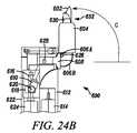
一態様において、生検要素600は、医療装置の切開部からの挿入、移送、および収納を一層容易に行えるように構成できる。図24Bは、図24Aに示す位置に対して90度の位置に配置された生検要素600のグラスパ632を示す。グラスパ632をこのように再び配置することは、上記のように、フレキシブル要素606A,606B,626の可撓性によって達成される。一実施形態によると、グラスパ632のこの第2位置は、グラスパ632が連結される装置の挿入および後退を一層容易にする。すなわちグラスパ632の第2位置は、切開口、ポート、または医療処置で使用される他の開口部もしくは装置に対する嵌合を一層容易にする。図24Aに示す動作位置において、グラスパ632は自身が連結されるロボット装置の本体に垂直に配置される。ロボット本体およびグラスパ632の全長は、ほとんどの腹腔鏡トロカールの直径よりも大きい。ロボット/グラスパ632をトロカールによって挿入可能にするために、グラスパ632は、支持機構を用いてロボット装置の長手方向に平行な位置に移動されてもよい。支持機構は、挿入時および後退時にトロカールによって、または適宜任意の開口部、切開口、または器具によって、アーム640を屈曲させる剛性および能力の両方を与える3つのフレキシブル要素606A,606B,626によって設けられる。生検サンプリング時、この支持機構は必要な剛性と力を提供し、生検の前後に行われる挿入および後退に必要な可撓性を与える。 In one aspect, the
あるいはこの概念を用いた様々な代替の支持機構が想定されてもよい。
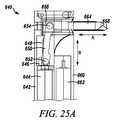
図25Aは、本明細書に開示のロボット装置で使用可能な生検要素640の代替実施形態を示す。生検要素640は、図24A、図24B、および図24Cに示す実施形態の作動要素と類似の作動要素(たとえばモータ644によって矢印Bで示す方向において送りネジ648の軸に沿って駆動されるナット646)を有する。ナット646は、リンケージ650によってスライダ656に取付けられる。リンケージ650は、ピン652においてナット646に連結され、ピン650においてスライダ656に連結される。Alternatively, various alternative support mechanisms using this concept may be envisaged.
FIG. 25A illustrates an alternative embodiment of a
本実施形態において、スライダ656は、図24に示すカラーと同じ機能を一般に実行する。すなわちスライダ656は、開孔要素658との関連で、矢印Aで示す方向に移動可能である。したがって、上記のカラーと同様に、スライダ656が上顎部664上を移動すると、上顎部664が開孔要素(すなわち下側の顎)658に対して閉じる。 In this embodiment, the
図26は、本明細書に記載のロボット装置で使用可能な生検要素660の代替実施形態を示す。生検要素660は、図24A、図24B、および図24Cに示す実施形態の作動要素と類似の作動要素を有する。本実施形態において、カラー662は方向Aに付勢される。カラー662が前進すると、上顎部664は方向Bにおいて下顎部666に向かって押し下げられる。カラー662は、図24と同様の方法でハウジング672によって定位置に保持される。 FIG. 26 illustrates an alternative embodiment of a
両方の顎部が回転軸を中心にヒンジ付けされている他の腹腔鏡生検鉗子とは異なり、ロボットグラスパの1つの顎部だけ(すなわち上顎部664)がサンプリング時に移動する。グラスパの下半分(すなわち下顎部666)は、静止状態にある。また上顎部664が切断を行える堅固で安定したベースを提供する。固定した下顎部666は、皮下医療ステンレス鋼チューブから構成され、複数のサンプルを収納するためのタンクを成す。 Unlike other laparoscopic biopsy forceps, where both jaws are hinged about the axis of rotation, only one jaw (ie, the upper jaw 664) of the robot grasper moves during sampling. The lower half (ie, the lower jaw 666) of the grass blade is stationary. The
一実施形態において、上顎部664の断面は厚さ0.25mm、幅3mmの超弾性形状記憶ニッケルチタニウム合金(ニチノール)リボン(Memry Corporation社製)から成る。グラスパの断面は、通常開いた状態である。リボンを約10分間、500℃で熱処理し、その後水中で焼き入れを行うことによって種々の断面が得られる。ニチノールリボンは、下顎部666内に嵌合する固定のナイロンロッド挿入物に対して接着される。 In one embodiment, the
グラスパのブレードは、長さが約1.5mmのチタン硝酸塩を被覆したステンレス鋼である。小型のプラスチック挿入物は上顎部および下顎部に固定され、これらの挿入物にブレード668,670が接着される。下顎部に固定された円形のブレード670の直径は3mmである。上側のブレード668は、直径が3.8mmの半円形状断面を有し、顎部が閉じると下側のブレードに重なる。上側のブレードの後縁によってサンプルが組織から切除されるため、サンプルは下側のブレード内に保持される。 The blade of the glass blade is stainless steel coated with titanium nitrate having a length of about 1.5 mm. Small plastic inserts are secured to the upper and lower jaws and
図27は、生検要素680の代替実施形態を示す。この生検要素680は、組織のステープリング(すなわち固定)またはクランピング(すなわち把持)を行うために、本明細書に開示のロボット装置で使用可能である。生検要素680は、図24A、図24B、および図24Cに示す実施形態の作動要素と類似の作動要素を有する。本実施形態において、カラー682は方向Aに付勢される。カラー682が前進すると、上顎部684が方向Bにおいて下顎部686に向かって押し下げられる。上顎部684が下顎部686に対して押し下げられると、小型の外科ステープル688が圧縮されて、関心のある組織のステープリング、または動脈もしくは他の血管の把持が可能となる。 FIG. 27 shows an alternative embodiment of
このステープリングアーム680は、一般の腹腔鏡外科ステープルを保持して閉じるように設計されている。このエンドエフェクタは、ステープリングに加えて把持および保持を要する用途(たとえば出血血管への圧力印加、または関心のある他の組織の処置)にも使用可能である。 The
図28Aと図28Bは、一実装例に係る生検機構690の他の実施形態を示す。これらの2つの図は、一実施形態に係るグラスパ顎部694,696の開閉について詳細に示す。具体的には、図28Aは、グラスパ顎部694,696が開いた構成の生検機構690を示す。本構成において、上顎部694は、先端が下顎部696の先端に接触しない位置にある。 28A and 28B show another embodiment of a
図28Bは、グラスパ顎部694,696が閉じた構成の生検機構690を示す。すなわちカラー698は、図28Aの後退位置から図28Bの伸展位置に移動されており、上顎部694と下顎部696を最終的に閉じた構成とすべく、カラー698は上顎部694を下顎部696に向かって押し下げるように付勢している。 FIG. 28B shows the
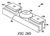
一実施形態によると、イメージング要素を有する、本明細書に記載または援用される医療装置のイメージング要素は、イメージング要素に組込まれる、またはイメージング要素と共に使用される焦点調節機構を有してもよい。このような焦点調節機構702の実装例を、図29A、図29B、図29C、図29D、および図29Eに示す。図29Eに最もよく示されるように、焦点調節機構702は、レンズアセンブリ704と、2つの磁気サブアセンブリ706とを有する。レンズアセンブリ704は、レンズ710と、配線712の2つのコイル(図29B、図29D、および図29Eに最もよく示される)と、レンズ710およびコイル712を1つのサブアセンブリに保持するレンズ保持要素714(図29A、図29D、および図29Eに最もよく示される)とを含む。図29Dと図29Eに最もよく示されるように、各磁気サブアセンブリ706は、鉄類から成るUチャネル722の一方の側に取付けられる小型体内磁石716を含む。レンズサブアセンブリ704は、2つの磁気サブアセンブリ706の間に配置される。コイル712はUチャネル722を通され、小型体内磁石716と、コイル712が配置されるUチャネル722の開口側との間に生成される磁場に配置される。磁界に配置されたコイル配線712に電流が通されると、レンズ710およびイメージャ718の軸に平行に電磁力が生成される。この電磁力は、電流の方向に対して垂直な磁界によって生成される。 According to one embodiment, an imaging element of a medical device described or incorporated herein having an imaging element may have a focusing mechanism that is incorporated into or used with the imaging element. Examples of mounting such a
一実施形態において、小型体内磁石716はペンシルベニア州ジャミソン(Jamis
on)のK and J Magnetics社製のネオジム磁石であり、コイル712はフロリダ州ノースフォートマイヤー(North Fort Myers)のPrecision Econowind社製であり、レンズ710はカリフォルニア州カールズバッドのSunex社製である。本実施形態において、磁石は0.98kg(2.17ポンド)の引張力と、2505ガウスの表面場を有している。一方、コイルはDSL758レンズを備える巻数120の36AWGの被覆銅線からなる。あるいは上記の要素は市販の要素であってもよい。In one embodiment, the miniature
on) K and J Magnetics, a neodymium magnet,
一実装例によると、レンズ保持要素714は、重量を最小にするためにポリカーボネートプラスチックによって製造される。図29Dと図29Eに示す実施形態において、体内磁石716は1.58mm×3.17mm×6.35mm(1/16インチ×1/8インチ×1/4インチ)であり、レンズサブアセンブリは、垂直方向の1ストロークが1mmである。 According to one implementation, the
一実施形態において、コイル配線からの電流を除去すると、レンズ710を付勢して休止位置に戻そうとする復元力が与えられる。これはレンズサブアセンブリの一定した移動を可能にし、レンズを焦点中央の最適範囲内に維持するのに用いられる。一実装例によると、図29Aと図29Bに最もよく示される復元力要素720は、発泡要素720である。あるいは復元力を与える既知の要素が使用されてもよい。 In one embodiment, removing the current from the coil wiring provides a restoring force that biases the
一実施形態によると、指示する深度にレンズをフォーカスすべく焦点調節機構702に指示を自動的に与えるために、焦点調節機構702は、自動フォーカスアルゴリズムに結合される。他の実施形態において、追加のレンズサブアセンブリ704と磁気サブアセンブリ706を組合せて、レンズ周囲に追加の深度調節ポイントを与えることができる。これらの追加の調節ポイントは、広範囲のレンズ配向角によって、アセンブリ製造時の誤差を修正可能にする。本実施形態において、製造誤差を修正すべくレンズを傾斜させるように、コイルには個別に指示が与えられる。 According to one embodiment, the
[実施例]
本実施例において、互いに異なる生検グラスパの断面および長さを検査した。たとえば生検機構の作動に必要な力、更に生検機構によって実際に印加され得る最大の力に対するこれらの断面および長さの効力を検査した。[Example]
In this example, the cross-sections and lengths of different biopsy glass paws were examined. For example, the effectiveness of these sections and lengths on the force required to operate the biopsy mechanism and the maximum force that could actually be applied by the biopsy mechanism was examined.
図30Aと図30Bは、一実施形態に係る生検機構を有する試験治具730を示す。図に示す試験治具730は、カラー738の作動時のナイロン支持ロッドの張力測定に用いたロードセル748を備えたものであった。また試験治具730の生検機構は、モータ732、リンケージ736、送りネジ734、カラー738、下顎部746、および上顎部744を有するものであった。 30A and 30B show a
顎部の長さ、開口角、および顎部断面が広範囲の各種グラスパの実施形態について、作動力がテストされた。顎部が閉じるまで上顎部744上でグラスパカラー738をスライドさせるためにモータ732と送りネジリンケージ736とを用いることによって、必要な作動力が決定された。各作動において、上顎部744が完全に開いた状態で必要な力の記録が開始され、上顎部744が閉じるまで継続された。作動処理時の異なる時間に応じた異なる位置に固定保持されたカラー738が印加した力を記録することによって、最大の作動力が決定された。各テスト全体において、生検グラスパは50回作動され、ロードセルデータは、各作動時に20Hzで記録された。 Actuation forces were tested on various glasspa embodiments with a wide range of jaw lengths, opening angles, and jaw cross sections. The required actuation force was determined by using a
図31は、グラスパに必要な力のテストの平均的な結果を示す。グラスパは長さが約12mm、開口角が25度であった。グラスパの切込チップは、断面における閉角が約40
度、長さが4mmであった。エラーバーは、約1.8秒の間隔で測定した力の標準偏差を示す。静止摩擦を抑えるため、およびグラスパの上顎部を曲げるため、カラーの動作開始時に必要な最大の作動力は2.83Nである。カラーと上顎部の間の接触点が固定点から離れるにしたがって、力は時間とともに減少する。テスト結果は、生検グラスパを閉じるのに必要とされる力が、最大約3Nであることを示す。FIG. 31 shows an average result of a test of the force required for the grass pas. The glass pas was about 12 mm long and the opening angle was 25 degrees. The cutting edge of the glass blade has a closing angle of about 40
The length was 4 mm. Error bars indicate the standard deviation of forces measured at approximately 1.8 second intervals. In order to suppress static friction and to bend the upper jaw portion of the glass blade, the maximum operating force required at the start of the operation of the collar is 2.83N. As the point of contact between the collar and upper jaw moves away from the fixed point, the force decreases with time. The test results show that the force required to close the biopsy glass is up to about 3N.
Claims (20)
Translated fromJapanese前記可動顎要素の先端は、前記固定顎要素に接しない位置に予め配置され、
前記第2スライディング位置の前記スライディング要素は、前記固定顎要素に向かって前記可動顎要素の先端を付勢するように、前記可動顎要素に接することを特徴とする、生検要素。A biopsy element comprising a fixed jaw element, a movable jaw element adjacent to the fixed jaw element, and a sliding element that moves between a first sliding position and a second sliding position,
The distal end of the movable jaw element is previously arranged at a position not in contact with the fixed jaw element,
The biopsy element, wherein the sliding element in the second sliding position contacts the movable jaw element so as to bias the tip of the movable jaw element toward the fixed jaw element.
前記固定顎要素の軸線は、前記第1固定位置の前記固定顎要素の軸線に対して、90度である、請求項2記載の生検要素。The flexible element allows the fixed jaw element to move from a first fixed position to a second fixed position;
The biopsy element of claim 2, wherein an axis of the fixed jaw element is 90 degrees with respect to an axis of the fixed jaw element in the first fixed position.
(b)前記第1連結要素に連結される第2連結要素を含む内表面を有する第1被駆動要素と;
(c)前記第1被駆動要素に連結される第1駆動要素と;
(d)前記第2被駆動要素内に形成される第2開口部を有する第2被駆動要素と;
(e)前記第1開口部と前記第2開口部に配置されたピンと;
(f)前記第2被駆動要素に連結される第2駆動要素と
を備えるアーム装置。(A) a variable-length rotary arm having an outer portion including a first connecting element and a first opening formed therein;
(B) a first driven element having an inner surface including a second coupling element coupled to the first coupling element;
(C) a first drive element coupled to the first driven element;
(D) a second driven element having a second opening formed in the second driven element;
(E) a pin disposed in the first opening and the second opening;
(F) An arm device comprising: a second driving element coupled to the second driven element.
(b)前記本体に関連付けられた第1ウィンチ要素と;
(c)前記第1ドラムに操作可能に連結される作動要素と
を備える医療装置であって、
前記第1ウィンチ要素は、第1ドラムと、前記第1ドラムに操作可能に連結される第1テザーとを含むことを特徴とする、医療装置。(A) the main body;
(B) a first winch element associated with the body;
(C) a medical device comprising an actuating element operably coupled to the first drum,
The medical device, wherein the first winch element includes a first drum and a first tether operably connected to the first drum.
前記第2ウィンチ要素は、第2ドラムと、前記第2ドラムに操作可能に連結される第2テザーとを含む、請求項15記載の医療装置。The medical device further comprises a second winch element;
The medical device of claim 15, wherein the second winch element includes a second drum and a second tether operably coupled to the second drum.
前記第3ウィンチ要素は、第3ドラムと、前記第3ドラムに操作可能に連結される第3テザーとを含む、請求項19記載の医療装置。The medical device further comprises a third winch element;
The medical device of claim 19, wherein the third winch element includes a third drum and a third tether operably coupled to the third drum.
Applications Claiming Priority (9)
| Application Number | Priority Date | Filing Date | Title |
|---|---|---|---|
| US94939007P | 2007-07-12 | 2007-07-12 | |
| US94939107P | 2007-07-12 | 2007-07-12 | |
| US60/949,390 | 2007-07-12 | ||
| US60/949,391 | 2007-07-12 | ||
| US99007607P | 2007-11-26 | 2007-11-26 | |
| US60/990,076 | 2007-11-26 | ||
| US2534608P | 2008-02-01 | 2008-02-01 | |
| US61/025,346 | 2008-02-01 | ||
| PCT/US2008/069822WO2009014917A2 (en) | 2007-07-12 | 2008-07-11 | Methods and systems of actuation in robotic devices |
Related Child Applications (1)
| Application Number | Title | Priority Date | Filing Date |
|---|---|---|---|
| JP2014154945ADivisionJP6250496B2 (en) | 2007-07-12 | 2014-07-30 | Robotic surgical system |
Publications (2)
| Publication Number | Publication Date |
|---|---|
| JP2010533045Atrue JP2010533045A (en) | 2010-10-21 |
| JP5591696B2 JP5591696B2 (en) | 2014-09-17 |
Family
ID=40282082
Family Applications (2)
| Application Number | Title | Priority Date | Filing Date |
|---|---|---|---|
| JP2010516278AExpired - Fee RelatedJP5591696B2 (en) | 2007-07-12 | 2008-07-11 | Biopsy elements, arm devices, and medical devices |
| JP2014154945AExpired - Fee RelatedJP6250496B2 (en) | 2007-07-12 | 2014-07-30 | Robotic surgical system |
Family Applications After (1)
| Application Number | Title | Priority Date | Filing Date |
|---|---|---|---|
| JP2014154945AExpired - Fee RelatedJP6250496B2 (en) | 2007-07-12 | 2014-07-30 | Robotic surgical system |
Country Status (5)
| Country | Link |
|---|---|
| US (5) | US8343171B2 (en) |
| EP (3) | EP3673855B1 (en) |
| JP (2) | JP5591696B2 (en) |
| CA (1) | CA2690808C (en) |
| WO (1) | WO2009014917A2 (en) |
Cited By (34)
| Publication number | Priority date | Publication date | Assignee | Title |
|---|---|---|---|---|
| JP2012526576A (en)* | 2009-05-15 | 2012-11-01 | クラッフェンベック,ヨハン | Medical equipment |
| JP2012239519A (en)* | 2011-05-16 | 2012-12-10 | Olympus Medical Systems Corp | Medical system |
| JP2015100677A (en)* | 2013-11-28 | 2015-06-04 | 国立大学法人東京工業大学 | Surgical robot |
| JP2015524702A (en)* | 2011-10-03 | 2015-08-27 | ボード オブ リージェンツ オブ ザ ユニバーシティ オブ ネブラスカ | Robotic surgical device, system and related methods |
| US9579088B2 (en) | 2007-02-20 | 2017-02-28 | Board Of Regents Of The University Of Nebraska | Methods, systems, and devices for surgical visualization and device manipulation |
| US9743987B2 (en) | 2013-03-14 | 2017-08-29 | Board Of Regents Of The University Of Nebraska | Methods, systems, and devices relating to robotic surgical devices, end effectors, and controllers |
| US9757187B2 (en) | 2011-06-10 | 2017-09-12 | Board Of Regents Of The University Of Nebraska | Methods, systems, and devices relating to surgical end effectors |
| US9770305B2 (en) | 2012-08-08 | 2017-09-26 | Board Of Regents Of The University Of Nebraska | Robotic surgical devices, systems, and related methods |
| US9883911B2 (en) | 2006-06-22 | 2018-02-06 | Board Of Regents Of The University Of Nebraska | Multifunctional operational component for robotic devices |
| US9888966B2 (en) | 2013-03-14 | 2018-02-13 | Board Of Regents Of The University Of Nebraska | Methods, systems, and devices relating to force control surgical systems |
| JP2018029990A (en)* | 2012-06-22 | 2018-03-01 | ボード オブ リージェンツ オブ ザ ユニバーシティ オブ ネブラスカ | Locally controlled robotic surgical device |
| US9956043B2 (en) | 2007-07-12 | 2018-05-01 | Board Of Regents Of The University Of Nebraska | Methods, systems, and devices for surgical access and procedures |
| US10111711B2 (en) | 2011-07-11 | 2018-10-30 | Board Of Regents Of The University Of Nebraska | Robotic surgical devices, systems, and related methods |
| US10219870B2 (en) | 2012-05-01 | 2019-03-05 | Board Of Regents Of The University Of Nebraska | Single site robotic device and related systems and methods |
| US10307199B2 (en) | 2006-06-22 | 2019-06-04 | Board Of Regents Of The University Of Nebraska | Robotic surgical devices and related methods |
| US10335024B2 (en) | 2007-08-15 | 2019-07-02 | Board Of Regents Of The University Of Nebraska | Medical inflation, attachment and delivery devices and related methods |
| US10342561B2 (en) | 2014-09-12 | 2019-07-09 | Board Of Regents Of The University Of Nebraska | Quick-release end effectors and related systems and methods |
| US10376322B2 (en) | 2014-11-11 | 2019-08-13 | Board Of Regents Of The University Of Nebraska | Robotic device with compact joint design and related systems and methods |
| US10582973B2 (en) | 2012-08-08 | 2020-03-10 | Virtual Incision Corporation | Robotic surgical devices, systems, and related methods |
| US10667883B2 (en) | 2013-03-15 | 2020-06-02 | Virtual Incision Corporation | Robotic surgical devices, systems, and related methods |
| US10702347B2 (en) | 2016-08-30 | 2020-07-07 | The Regents Of The University Of California | Robotic device with compact joint design and an additional degree of freedom and related systems and methods |
| US10722319B2 (en) | 2016-12-14 | 2020-07-28 | Virtual Incision Corporation | Releasable attachment device for coupling to medical devices and related systems and methods |
| US10751136B2 (en) | 2016-05-18 | 2020-08-25 | Virtual Incision Corporation | Robotic surgical devices, systems and related methods |
| US10806538B2 (en) | 2015-08-03 | 2020-10-20 | Virtual Incision Corporation | Robotic surgical devices, systems, and related methods |
| US10966700B2 (en) | 2013-07-17 | 2021-04-06 | Virtual Incision Corporation | Robotic surgical devices, systems and related methods |
| US11013564B2 (en) | 2018-01-05 | 2021-05-25 | Board Of Regents Of The University Of Nebraska | Single-arm robotic device with compact joint design and related systems and methods |
| US11051894B2 (en) | 2017-09-27 | 2021-07-06 | Virtual Incision Corporation | Robotic surgical devices with tracking camera technology and related systems and methods |
| US11173617B2 (en) | 2016-08-25 | 2021-11-16 | Board Of Regents Of The University Of Nebraska | Quick-release end effector tool interface |
| US11284958B2 (en) | 2016-11-29 | 2022-03-29 | Virtual Incision Corporation | User controller with user presence detection and related systems and methods |
| US11357595B2 (en) | 2016-11-22 | 2022-06-14 | Board Of Regents Of The University Of Nebraska | Gross positioning device and related systems and methods |
| US11883065B2 (en) | 2012-01-10 | 2024-01-30 | Board Of Regents Of The University Of Nebraska | Methods, systems, and devices for surgical access and insertion |
| US11903658B2 (en) | 2019-01-07 | 2024-02-20 | Virtual Incision Corporation | Robotically assisted surgical system and related devices and methods |
| US12150722B2 (en) | 2020-07-06 | 2024-11-26 | Virtual Incision Corporation | Surgical robot positioning system and related devices and methods |
| US12295680B2 (en) | 2012-08-08 | 2025-05-13 | Board Of Regents Of The University Of Nebraska | Robotic surgical devices, systems and related methods |
Families Citing this family (199)
| Publication number | Priority date | Publication date | Assignee | Title |
|---|---|---|---|---|
| US20080058989A1 (en)* | 2006-04-13 | 2008-03-06 | Board Of Regents Of The University Of Nebraska | Surgical camera robot |
| US7960935B2 (en) | 2003-07-08 | 2011-06-14 | The Board Of Regents Of The University Of Nebraska | Robotic devices with agent delivery components and related methods |
| SG132553A1 (en)* | 2005-11-28 | 2007-06-28 | Pang Ah San | A device for laparoscopic or thoracoscopic surgery |
| US8219178B2 (en) | 2007-02-16 | 2012-07-10 | Catholic Healthcare West | Method and system for performing invasive medical procedures using a surgical robot |
| US10357184B2 (en) | 2012-06-21 | 2019-07-23 | Globus Medical, Inc. | Surgical tool systems and method |
| US10653497B2 (en) | 2006-02-16 | 2020-05-19 | Globus Medical, Inc. | Surgical tool systems and methods |
| US10893912B2 (en) | 2006-02-16 | 2021-01-19 | Globus Medical Inc. | Surgical tool systems and methods |
| US9144909B2 (en)* | 2007-07-05 | 2015-09-29 | Re2, Inc. | Defense related robotic systems |
| CA2695619C (en) | 2007-08-15 | 2015-11-24 | Board Of Regents Of The University Of Nebraska | Modular and cooperative medical devices and related systems and methods |
| CA2706860C (en) | 2007-11-26 | 2017-08-01 | Eastern Virginia Medical School | Magnaretractor system and method |
| US8647258B2 (en)* | 2008-01-10 | 2014-02-11 | Covidien Lp | Apparatus for endoscopic procedures |
| FR2934486B1 (en)* | 2008-07-29 | 2012-08-17 | Univ Joseph Fourier Grenoble I | MODULAR SURGICAL TOOL |
| CL2009000279A1 (en) | 2009-02-06 | 2009-08-14 | Biotech Innovations Ltda | Remote guidance and traction system for mini-invasive surgery, comprising: at least one surgical and removable endopinza with hooking means and a portion of ferro-magnaetic material, a cylindrical introduction guide, a detachment mechanism, and at least a means of remote traction with magnet. |
| US10507071B2 (en)* | 2009-05-11 | 2019-12-17 | Carefusion 2200, Inc. | Hand actuated, articulating device having an electric force enhancement system |
| KR101241809B1 (en)* | 2009-07-31 | 2013-03-14 | (주)미래컴퍼니 | Surgical robot |
| EP2286756B1 (en)* | 2009-08-21 | 2013-04-03 | Novineon Healthcare Technology Partners Gmbh | Surgical manipulator means |
| US20110087224A1 (en)* | 2009-10-09 | 2011-04-14 | Cadeddu Jeffrey A | Magnetic surgical sled with variable arm |
| US8623011B2 (en) | 2009-10-09 | 2014-01-07 | Ethicon Endo-Surgery, Inc. | Magnetic surgical sled with locking arm |
| US8870759B2 (en)* | 2009-12-04 | 2014-10-28 | Covidien Lp | Suspension system for minimally invasive surgery |
| US8747309B2 (en) | 2010-11-09 | 2014-06-10 | Covidien Lp | Suspension system for minimally invasive surgery |
| WO2011075693A1 (en)* | 2009-12-17 | 2011-06-23 | Board Of Regents Of The University Of Nebraska | Modular and cooperative medical devices and related systems and methods |
| JP2011156267A (en)* | 2010-02-03 | 2011-08-18 | Olympus Medical Systems Corp | Medical device |
| EP2600758A1 (en) | 2010-08-06 | 2013-06-12 | Board of Regents of the University of Nebraska | Methods and systems for handling or delivering materials for natural orifice surgery |
| JP4829388B1 (en)* | 2010-08-25 | 2011-12-07 | オリンパスメディカルシステムズ株式会社 | Medical equipment |
| EP2422935B1 (en) | 2010-08-31 | 2015-02-25 | Kabushiki Kaisha Yaskawa Denki | Robot, robot system, robot control device, and state determining method |
| DE102010040405B4 (en)* | 2010-09-08 | 2017-07-27 | Siemens Healthcare Gmbh | Instrument system for an endoscopic robot |
| WO2012047939A2 (en)* | 2010-10-04 | 2012-04-12 | Ind Platforms Llc | Expandable devices, rail systems, and motorized devices |
| US9308050B2 (en) | 2011-04-01 | 2016-04-12 | Ecole Polytechnique Federale De Lausanne (Epfl) | Robotic system and method for spinal and other surgeries |
| ITFI20110114A1 (en)* | 2011-05-31 | 2012-12-01 | Scuola Superiore Di Studi Universit Arie Di Perfe | ROBOTIC PLATFORM FOR MINING-INVASIVE SURGERY |
| US8833188B1 (en)* | 2011-06-30 | 2014-09-16 | Bae Systems Information And Electronic Systems Integration Inc. | High speed pneumatic simulation facility |
| US8682416B2 (en)* | 2011-07-08 | 2014-03-25 | American Gnc Corporation | Robotic module for natural orifice transluminal endoscopic surgery (NOTES) |
| US20130158659A1 (en)* | 2011-12-20 | 2013-06-20 | Richard A. Bergs | Medical Devices, Apparatuses, Systems, and Methods With Configurations for Shaping Magnetic-Fields and Interactions |
| US8891924B2 (en) | 2012-04-26 | 2014-11-18 | Bio-Medical Engineering (HK) Limited | Magnetic-anchored robotic system |
| US10179033B2 (en) | 2012-04-26 | 2019-01-15 | Bio-Medical Engineering (HK) Limited | Magnetic-anchored robotic system |
| US9737364B2 (en) | 2012-05-14 | 2017-08-22 | Vanderbilt University | Local magnetic actuation of surgical devices |
| US20150032164A1 (en) | 2012-06-21 | 2015-01-29 | Globus Medical, Inc. | Methods for Performing Invasive Medical Procedures Using a Surgical Robot |
| US10231791B2 (en) | 2012-06-21 | 2019-03-19 | Globus Medical, Inc. | Infrared signal based position recognition system for use with a robot-assisted surgery |
| US12220120B2 (en) | 2012-06-21 | 2025-02-11 | Globus Medical, Inc. | Surgical robotic system with retractor |
| US11857266B2 (en) | 2012-06-21 | 2024-01-02 | Globus Medical, Inc. | System for a surveillance marker in robotic-assisted surgery |
| US12310683B2 (en) | 2012-06-21 | 2025-05-27 | Globus Medical, Inc. | Surgical tool systems and method |
| US11298196B2 (en) | 2012-06-21 | 2022-04-12 | Globus Medical Inc. | Surgical robotic automation with tracking markers and controlled tool advancement |
| US11857149B2 (en) | 2012-06-21 | 2024-01-02 | Globus Medical, Inc. | Surgical robotic systems with target trajectory deviation monitoring and related methods |
| US12329593B2 (en) | 2012-06-21 | 2025-06-17 | Globus Medical, Inc. | Surgical robotic automation with tracking markers |
| US11793570B2 (en) | 2012-06-21 | 2023-10-24 | Globus Medical Inc. | Surgical robotic automation with tracking markers |
| US11864745B2 (en) | 2012-06-21 | 2024-01-09 | Globus Medical, Inc. | Surgical robotic system with retractor |
| US10350013B2 (en) | 2012-06-21 | 2019-07-16 | Globus Medical, Inc. | Surgical tool systems and methods |
| US11399900B2 (en) | 2012-06-21 | 2022-08-02 | Globus Medical, Inc. | Robotic systems providing co-registration using natural fiducials and related methods |
| US10624710B2 (en) | 2012-06-21 | 2020-04-21 | Globus Medical, Inc. | System and method for measuring depth of instrumentation |
| US11864839B2 (en) | 2012-06-21 | 2024-01-09 | Globus Medical Inc. | Methods of adjusting a virtual implant and related surgical navigation systems |
| US11317971B2 (en) | 2012-06-21 | 2022-05-03 | Globus Medical, Inc. | Systems and methods related to robotic guidance in surgery |
| US10136954B2 (en) | 2012-06-21 | 2018-11-27 | Globus Medical, Inc. | Surgical tool systems and method |
| US11607149B2 (en) | 2012-06-21 | 2023-03-21 | Globus Medical Inc. | Surgical tool systems and method |
| US12004905B2 (en) | 2012-06-21 | 2024-06-11 | Globus Medical, Inc. | Medical imaging systems using robotic actuators and related methods |
| US11974822B2 (en) | 2012-06-21 | 2024-05-07 | Globus Medical Inc. | Method for a surveillance marker in robotic-assisted surgery |
| US11116576B2 (en) | 2012-06-21 | 2021-09-14 | Globus Medical Inc. | Dynamic reference arrays and methods of use |
| US11045267B2 (en) | 2012-06-21 | 2021-06-29 | Globus Medical, Inc. | Surgical robotic automation with tracking markers |
| US11395706B2 (en) | 2012-06-21 | 2022-07-26 | Globus Medical Inc. | Surgical robot platform |
| US12262954B2 (en) | 2012-06-21 | 2025-04-01 | Globus Medical, Inc. | Surgical robotic automation with tracking markers |
| US10758315B2 (en) | 2012-06-21 | 2020-09-01 | Globus Medical Inc. | Method and system for improving 2D-3D registration convergence |
| EP2863827B1 (en) | 2012-06-21 | 2022-11-16 | Globus Medical, Inc. | Surgical robot platform |
| US11253327B2 (en) | 2012-06-21 | 2022-02-22 | Globus Medical, Inc. | Systems and methods for automatically changing an end-effector on a surgical robot |
| US20140005640A1 (en) | 2012-06-28 | 2014-01-02 | Ethicon Endo-Surgery, Inc. | Surgical end effector jaw and electrode configurations |
| US9826904B2 (en) | 2012-09-14 | 2017-11-28 | Vanderbilt University | System and method for detecting tissue surface properties |
| KR101293282B1 (en)* | 2013-01-11 | 2013-08-09 | 아주대학교산학협력단 | Surgical retractor |
| US10485409B2 (en) | 2013-01-17 | 2019-11-26 | Vanderbilt University | Real-time pose and magnetic force detection for wireless magnetic capsule |
| US8764769B1 (en) | 2013-03-12 | 2014-07-01 | Levita Magnetics International Corp. | Grasper with magnetically-controlled positioning |
| US10010370B2 (en) | 2013-03-14 | 2018-07-03 | Levita Magnetics International Corp. | Magnetic control assemblies and systems therefor |
| US20140276394A1 (en) | 2013-03-15 | 2014-09-18 | Hansen Medical, Inc. | Input device for controlling a catheter |
| US9498291B2 (en) | 2013-03-15 | 2016-11-22 | Hansen Medical, Inc. | Touch-free catheter user interface controller |
| ITMI20130666A1 (en)* | 2013-04-23 | 2014-10-24 | Valuebiotech S R L | ROBOT STRUCTURE, PARTICULARLY FOR MINI-INVASIVE SURGERY THROUGH SINGLE PARIETAL ENGRAVING OR NATURAL ORIFICE. |
| US9283048B2 (en) | 2013-10-04 | 2016-03-15 | KB Medical SA | Apparatus and systems for precise guidance of surgical tools |
| US9241771B2 (en) | 2014-01-15 | 2016-01-26 | KB Medical SA | Notched apparatus for guidance of an insertable instrument along an axis during spinal surgery |
| WO2015112645A1 (en) | 2014-01-21 | 2015-07-30 | Levita Magnetics International Corp. | Laparoscopic graspers and systems therefor |
| WO2015121311A1 (en) | 2014-02-11 | 2015-08-20 | KB Medical SA | Sterile handle for controlling a robotic surgical system from a sterile field |
| JP6351293B2 (en)* | 2014-02-20 | 2018-07-04 | キヤノン株式会社 | Robot system and article manufacturing method |
| KR102470468B1 (en)* | 2014-03-17 | 2022-11-25 | 인튜어티브 서지컬 오퍼레이션즈 인코포레이티드 | System and method for aligning with a reference target |
| EP3134022B1 (en) | 2014-04-24 | 2018-01-10 | KB Medical SA | Surgical instrument holder for use with a robotic surgical system |
| JP2017514608A (en) | 2014-05-05 | 2017-06-08 | バイカリアス サージカル インク. | Virtual reality surgical device |
| CN103976792B (en)* | 2014-06-04 | 2016-03-23 | 哈尔滨工业大学 | Self-cleaning and tilt-adjustable transmission mechanism for an intraperitoneal vision robotic cell |
| US10357257B2 (en) | 2014-07-14 | 2019-07-23 | KB Medical SA | Anti-skid surgical instrument for use in preparing holes in bone tissue |
| CN104146779B (en)* | 2014-08-22 | 2016-03-23 | 哈尔滨工业大学 | A lever slip ring cam reciprocating transmission mechanism for intra-abdominal vision robot |
| US10758111B2 (en) | 2014-09-09 | 2020-09-01 | Vanderbilt University | Hydro-jet endoscopic capsule and methods for gastric cancer screening in low resource settings |
| EP3226781B1 (en) | 2014-12-02 | 2018-08-01 | KB Medical SA | Robot assisted volume removal during surgery |
| US10013808B2 (en) | 2015-02-03 | 2018-07-03 | Globus Medical, Inc. | Surgeon head-mounted display apparatuses |
| WO2016131903A1 (en) | 2015-02-18 | 2016-08-25 | KB Medical SA | Systems and methods for performing minimally invasive spinal surgery with a robotic surgical system using a percutaneous technique |
| JP6486715B2 (en)* | 2015-02-25 | 2019-03-20 | 日本トムソン株式会社 | Articulated forceps |
| WO2016168377A1 (en)* | 2015-04-13 | 2016-10-20 | Levita Magnetics International Corp. | Retractor systems, devices, and methods for use |
| ES2895900T3 (en) | 2015-04-13 | 2022-02-23 | Levita Magnetics Int Corp | Magnetically controlled location handle |
| US10603195B1 (en) | 2015-05-20 | 2020-03-31 | Paul Sherburne | Radial expansion and contraction features of medical devices |
| US10646298B2 (en) | 2015-07-31 | 2020-05-12 | Globus Medical, Inc. | Robot arm and methods of use |
| US10058394B2 (en) | 2015-07-31 | 2018-08-28 | Globus Medical, Inc. | Robot arm and methods of use |
| US10080615B2 (en) | 2015-08-12 | 2018-09-25 | Globus Medical, Inc. | Devices and methods for temporary mounting of parts to bone |
| JP6894431B2 (en) | 2015-08-31 | 2021-06-30 | ケービー メディカル エスアー | Robotic surgical system and method |
| US10034716B2 (en) | 2015-09-14 | 2018-07-31 | Globus Medical, Inc. | Surgical robotic systems and methods thereof |
| US10292777B1 (en)* | 2015-09-18 | 2019-05-21 | Elytra Technologies, Llc | Device and method for controlled motion of a tool |
| US9771092B2 (en) | 2015-10-13 | 2017-09-26 | Globus Medical, Inc. | Stabilizer wheel assembly and methods of use |
| ITUB20155057A1 (en) | 2015-10-16 | 2017-04-16 | Medical Microinstruments S R L | Robotic surgery set |
| EP3399902B1 (en) | 2016-01-08 | 2024-06-12 | Levita Magnetics International Corp. | One-operator surgical system |
| US11376087B2 (en) | 2016-01-12 | 2022-07-05 | Intuitive Surgical Operations, Inc. | Uniform scaling of haptic actuators |
| JP7590072B2 (en) | 2016-01-12 | 2024-11-26 | インテュイティブ サージカル オペレーションズ, インコーポレイテッド | Gradual force-feedback transitions between control states |
| US10117632B2 (en) | 2016-02-03 | 2018-11-06 | Globus Medical, Inc. | Portable medical imaging system with beam scanning collimator |
| US10448910B2 (en) | 2016-02-03 | 2019-10-22 | Globus Medical, Inc. | Portable medical imaging system |
| US11058378B2 (en) | 2016-02-03 | 2021-07-13 | Globus Medical, Inc. | Portable medical imaging system |
| US10842453B2 (en) | 2016-02-03 | 2020-11-24 | Globus Medical, Inc. | Portable medical imaging system |
| US11883217B2 (en) | 2016-02-03 | 2024-01-30 | Globus Medical, Inc. | Portable medical imaging system and method |
| US10866119B2 (en) | 2016-03-14 | 2020-12-15 | Globus Medical, Inc. | Metal detector for detecting insertion of a surgical device into a hollow tube |
| EP3241518B1 (en) | 2016-04-11 | 2024-10-23 | Globus Medical, Inc | Surgical tool systems |
| JP6577936B2 (en)* | 2016-12-27 | 2019-09-18 | 川崎重工業株式会社 | Hydraulic forceps system |
| JP7233841B2 (en) | 2017-01-18 | 2023-03-07 | ケービー メディカル エスアー | Robotic Navigation for Robotic Surgical Systems |
| US11199545B2 (en)* | 2017-01-31 | 2021-12-14 | Asensus Surgical Us, Inc. | Hydraulic instrument drive system for minimally invasive surgery |
| US10799308B2 (en) | 2017-02-09 | 2020-10-13 | Vicarious Surgical Inc. | Virtual reality surgical tools system |
| US11071594B2 (en) | 2017-03-16 | 2021-07-27 | KB Medical SA | Robotic navigation of robotic surgical systems |
| US11020137B2 (en) | 2017-03-20 | 2021-06-01 | Levita Magnetics International Corp. | Directable traction systems and methods |
| US10471605B2 (en)* | 2017-04-26 | 2019-11-12 | Ready Robotics | Programmable adapters for detachably connecting robotic peripherals to adaptively retool robots |
| US11135015B2 (en) | 2017-07-21 | 2021-10-05 | Globus Medical, Inc. | Robot surgical platform |
| WO2019055681A1 (en) | 2017-09-14 | 2019-03-21 | Vicarious Surgical Inc. | Virtual reality surgical camera system |
| CN111386085B (en)* | 2017-10-02 | 2023-12-26 | 直观外科手术操作公司 | End effector force feedback to master controller |
| US11122965B2 (en) | 2017-10-09 | 2021-09-21 | Vanderbilt University | Robotic capsule system with magnetic actuation and localization |
| US11357548B2 (en) | 2017-11-09 | 2022-06-14 | Globus Medical, Inc. | Robotic rod benders and related mechanical and motor housings |
| EP3492032B1 (en) | 2017-11-09 | 2023-01-04 | Globus Medical, Inc. | Surgical robotic systems for bending surgical rods |
| US11794338B2 (en) | 2017-11-09 | 2023-10-24 | Globus Medical Inc. | Robotic rod benders and related mechanical and motor housings |
| US11134862B2 (en) | 2017-11-10 | 2021-10-05 | Globus Medical, Inc. | Methods of selecting surgical implants and related devices |
| US20190254753A1 (en) | 2018-02-19 | 2019-08-22 | Globus Medical, Inc. | Augmented reality navigation systems for use with robotic surgical systems and methods of their use |
| US10573023B2 (en) | 2018-04-09 | 2020-02-25 | Globus Medical, Inc. | Predictive visualization of medical imaging scanner component movement |
| US11497490B2 (en)* | 2018-07-09 | 2022-11-15 | Covidien Lp | Powered surgical devices including predictive motor control |
| US11337742B2 (en) | 2018-11-05 | 2022-05-24 | Globus Medical Inc | Compliant orthopedic driver |
| US11278360B2 (en) | 2018-11-16 | 2022-03-22 | Globus Medical, Inc. | End-effectors for surgical robotic systems having sealed optical components |
| US11744655B2 (en) | 2018-12-04 | 2023-09-05 | Globus Medical, Inc. | Drill guide fixtures, cranial insertion fixtures, and related methods and robotic systems |
| US11602402B2 (en) | 2018-12-04 | 2023-03-14 | Globus Medical, Inc. | Drill guide fixtures, cranial insertion fixtures, and related methods and robotic systems |
| JP7372513B2 (en)* | 2018-12-05 | 2023-11-01 | ミツミ電機株式会社 | Imaging devices, imaging systems, and industrial robots |
| JP2020141862A (en)* | 2019-03-06 | 2020-09-10 | 川崎重工業株式会社 | Hydraulic medical equipment and surgery support robots |
| US11918313B2 (en) | 2019-03-15 | 2024-03-05 | Globus Medical Inc. | Active end effectors for surgical robots |
| US11571265B2 (en) | 2019-03-22 | 2023-02-07 | Globus Medical Inc. | System for neuronavigation registration and robotic trajectory guidance, robotic surgery, and related methods and devices |
| US11806084B2 (en) | 2019-03-22 | 2023-11-07 | Globus Medical, Inc. | System for neuronavigation registration and robotic trajectory guidance, and related methods and devices |
| US11419616B2 (en) | 2019-03-22 | 2022-08-23 | Globus Medical, Inc. | System for neuronavigation registration and robotic trajectory guidance, robotic surgery, and related methods and devices |
| US20200297357A1 (en) | 2019-03-22 | 2020-09-24 | Globus Medical, Inc. | System for neuronavigation registration and robotic trajectory guidance, robotic surgery, and related methods and devices |
| US11382549B2 (en) | 2019-03-22 | 2022-07-12 | Globus Medical, Inc. | System for neuronavigation registration and robotic trajectory guidance, and related methods and devices |
| US11317978B2 (en) | 2019-03-22 | 2022-05-03 | Globus Medical, Inc. | System for neuronavigation registration and robotic trajectory guidance, robotic surgery, and related methods and devices |
| US11045179B2 (en) | 2019-05-20 | 2021-06-29 | Global Medical Inc | Robot-mounted retractor system |
| US11723729B2 (en) | 2019-06-27 | 2023-08-15 | Cilag Gmbh International | Robotic surgical assembly coupling safety mechanisms |
| US11607278B2 (en) | 2019-06-27 | 2023-03-21 | Cilag Gmbh International | Cooperative robotic surgical systems |
| US11547468B2 (en) | 2019-06-27 | 2023-01-10 | Cilag Gmbh International | Robotic surgical system with safety and cooperative sensing control |
| US11413102B2 (en) | 2019-06-27 | 2022-08-16 | Cilag Gmbh International | Multi-access port for surgical robotic systems |
| US11376082B2 (en) | 2019-06-27 | 2022-07-05 | Cilag Gmbh International | Robotic surgical system with local sensing of functional parameters based on measurements of multiple physical inputs |
| US11612445B2 (en) | 2019-06-27 | 2023-03-28 | Cilag Gmbh International | Cooperative operation of robotic arms |
| US11628023B2 (en) | 2019-07-10 | 2023-04-18 | Globus Medical, Inc. | Robotic navigational system for interbody implants |
| US12396692B2 (en) | 2019-09-24 | 2025-08-26 | Globus Medical, Inc. | Compound curve cable chain |
| US11571171B2 (en) | 2019-09-24 | 2023-02-07 | Globus Medical, Inc. | Compound curve cable chain |
| US11890066B2 (en) | 2019-09-30 | 2024-02-06 | Globus Medical, Inc | Surgical robot with passive end effector |
| US11864857B2 (en) | 2019-09-27 | 2024-01-09 | Globus Medical, Inc. | Surgical robot with passive end effector |
| US11426178B2 (en) | 2019-09-27 | 2022-08-30 | Globus Medical Inc. | Systems and methods for navigating a pin guide driver |
| US12408929B2 (en) | 2019-09-27 | 2025-09-09 | Globus Medical, Inc. | Systems and methods for navigating a pin guide driver |
| US12329391B2 (en) | 2019-09-27 | 2025-06-17 | Globus Medical, Inc. | Systems and methods for robot-assisted knee arthroplasty surgery |
| US11510684B2 (en) | 2019-10-14 | 2022-11-29 | Globus Medical, Inc. | Rotary motion passive end effector for surgical robots in orthopedic surgeries |
| US12133772B2 (en) | 2019-12-10 | 2024-11-05 | Globus Medical, Inc. | Augmented reality headset for navigated robotic surgery |
| US11992373B2 (en) | 2019-12-10 | 2024-05-28 | Globus Medical, Inc | Augmented reality headset with varied opacity for navigated robotic surgery |
| US12220176B2 (en) | 2019-12-10 | 2025-02-11 | Globus Medical, Inc. | Extended reality instrument interaction zone for navigated robotic |
| US12290258B2 (en)* | 2019-12-13 | 2025-05-06 | Dinesh Vyas | Stapler apparatus and methods for use |
| US12064189B2 (en) | 2019-12-13 | 2024-08-20 | Globus Medical, Inc. | Navigated instrument for use in robotic guided surgery |
| US11382699B2 (en) | 2020-02-10 | 2022-07-12 | Globus Medical Inc. | Extended reality visualization of optical tool tracking volume for computer assisted navigation in surgery |
| US12414752B2 (en) | 2020-02-17 | 2025-09-16 | Globus Medical, Inc. | System and method of determining optimal 3-dimensional position and orientation of imaging device for imaging patient bones |
| US11207150B2 (en) | 2020-02-19 | 2021-12-28 | Globus Medical, Inc. | Displaying a virtual model of a planned instrument attachment to ensure correct selection of physical instrument attachment |
| US11253216B2 (en) | 2020-04-28 | 2022-02-22 | Globus Medical Inc. | Fixtures for fluoroscopic imaging systems and related navigation systems and methods |
| US11510750B2 (en) | 2020-05-08 | 2022-11-29 | Globus Medical, Inc. | Leveraging two-dimensional digital imaging and communication in medicine imagery in three-dimensional extended reality applications |
| US11382700B2 (en) | 2020-05-08 | 2022-07-12 | Globus Medical Inc. | Extended reality headset tool tracking and control |
| US11153555B1 (en) | 2020-05-08 | 2021-10-19 | Globus Medical Inc. | Extended reality headset camera system for computer assisted navigation in surgery |
| US11317973B2 (en) | 2020-06-09 | 2022-05-03 | Globus Medical, Inc. | Camera tracking bar for computer assisted navigation during surgery |
| US12070276B2 (en) | 2020-06-09 | 2024-08-27 | Globus Medical Inc. | Surgical object tracking in visible light via fiducial seeding and synthetic image registration |
| US11382713B2 (en) | 2020-06-16 | 2022-07-12 | Globus Medical, Inc. | Navigated surgical system with eye to XR headset display calibration |
| US11877807B2 (en) | 2020-07-10 | 2024-01-23 | Globus Medical, Inc | Instruments for navigated orthopedic surgeries |
| US11793588B2 (en) | 2020-07-23 | 2023-10-24 | Globus Medical, Inc. | Sterile draping of robotic arms |
| US11737831B2 (en) | 2020-09-02 | 2023-08-29 | Globus Medical Inc. | Surgical object tracking template generation for computer assisted navigation during surgical procedure |
| US11523785B2 (en) | 2020-09-24 | 2022-12-13 | Globus Medical, Inc. | Increased cone beam computed tomography volume length without requiring stitching or longitudinal C-arm movement |
| US11911112B2 (en) | 2020-10-27 | 2024-02-27 | Globus Medical, Inc. | Robotic navigational system |
| US12076091B2 (en) | 2020-10-27 | 2024-09-03 | Globus Medical, Inc. | Robotic navigational system |
| US11941814B2 (en) | 2020-11-04 | 2024-03-26 | Globus Medical Inc. | Auto segmentation using 2-D images taken during 3-D imaging spin |
| US11717350B2 (en) | 2020-11-24 | 2023-08-08 | Globus Medical Inc. | Methods for robotic assistance and navigation in spinal surgery and related systems |
| US12161433B2 (en) | 2021-01-08 | 2024-12-10 | Globus Medical, Inc. | System and method for ligament balancing with robotic assistance |
| US12150728B2 (en) | 2021-04-14 | 2024-11-26 | Globus Medical, Inc. | End effector for a surgical robot |
| US12178523B2 (en) | 2021-04-19 | 2024-12-31 | Globus Medical, Inc. | Computer assisted surgical navigation system for spine procedures |
| US11931026B2 (en) | 2021-06-30 | 2024-03-19 | Cilag Gmbh International | Staple cartridge replacement |
| US11974829B2 (en) | 2021-06-30 | 2024-05-07 | Cilag Gmbh International | Link-driven articulation device for a surgical device |
| US12358136B2 (en) | 2021-06-30 | 2025-07-15 | Cilag Gmbh International | Grasping work determination and indications thereof |
| US11857273B2 (en) | 2021-07-06 | 2024-01-02 | Globus Medical, Inc. | Ultrasonic robotic surgical navigation |
| US11439444B1 (en) | 2021-07-22 | 2022-09-13 | Globus Medical, Inc. | Screw tower and rod reduction tool |
| US12213745B2 (en) | 2021-09-16 | 2025-02-04 | Globus Medical, Inc. | Extended reality systems for visualizing and controlling operating room equipment |
| US12184636B2 (en) | 2021-10-04 | 2024-12-31 | Globus Medical, Inc. | Validating credential keys based on combinations of credential value strings and input order strings |
| US12238087B2 (en) | 2021-10-04 | 2025-02-25 | Globus Medical, Inc. | Validating credential keys based on combinations of credential value strings and input order strings |
| US20230368330A1 (en) | 2021-10-20 | 2023-11-16 | Globus Medical, Inc. | Interpolation of medical images |
| US20230165639A1 (en) | 2021-12-01 | 2023-06-01 | Globus Medical, Inc. | Extended reality systems with three-dimensional visualizations of medical image scan slices |
| US11911115B2 (en) | 2021-12-20 | 2024-02-27 | Globus Medical Inc. | Flat panel registration fixture and method of using same |
| US12103480B2 (en) | 2022-03-18 | 2024-10-01 | Globus Medical Inc. | Omni-wheel cable pusher |
| US12048493B2 (en) | 2022-03-31 | 2024-07-30 | Globus Medical, Inc. | Camera tracking system identifying phantom markers during computer assisted surgery navigation |
| US12394086B2 (en) | 2022-05-10 | 2025-08-19 | Globus Medical, Inc. | Accuracy check and automatic calibration of tracked instruments |
| US12161427B2 (en) | 2022-06-08 | 2024-12-10 | Globus Medical, Inc. | Surgical navigation system with flat panel registration fixture |
| US20240020840A1 (en) | 2022-07-15 | 2024-01-18 | Globus Medical, Inc. | REGISTRATION OF 3D and 2D IMAGES FOR SURGICAL NAVIGATION AND ROBOTIC GUIDANCE WITHOUT USING RADIOPAQUE FIDUCIALS IN THE IMAGES |
| US12226169B2 (en) | 2022-07-15 | 2025-02-18 | Globus Medical, Inc. | Registration of 3D and 2D images for surgical navigation and robotic guidance without using radiopaque fiducials in the images |
| US12318150B2 (en) | 2022-10-11 | 2025-06-03 | Globus Medical Inc. | Camera tracking system for computer assisted surgery navigation |
| CN118285730B (en)* | 2024-04-24 | 2024-10-01 | 西安交通大学 | Gastrointestinal tract disease in vivo biopsy diagnosis robot |
Citations (1)
| Publication number | Priority date | Publication date | Assignee | Title |
|---|---|---|---|---|
| WO2006052927A2 (en)* | 2004-11-08 | 2006-05-18 | The Johns Hopkins University | Bioptome |
Family Cites Families (399)
| Publication number | Priority date | Publication date | Assignee | Title |
|---|---|---|---|---|
| US3870264A (en) | 1973-03-26 | 1975-03-11 | William I Robinson | Stand |
| DE2339827B2 (en) | 1973-08-06 | 1977-02-24 | A6 In 3-02 | DENTAL EQUIPMENT |
| US4258716A (en) | 1978-02-06 | 1981-03-31 | The University Of Melbourne | Microsurgical instruments |
| JPS5519124A (en) | 1978-07-27 | 1980-02-09 | Olympus Optical Co | Camera system for medical treatment |
| US4246661A (en) | 1979-03-15 | 1981-01-27 | The Boeing Company | Digitally-controlled artificial hand |
| US4483562A (en)* | 1981-10-16 | 1984-11-20 | Arnold Schoolman | Locking flexible shaft device with live distal end attachment |
| JPS58132490A (en) | 1982-01-29 | 1983-08-06 | 株式会社日立製作所 | Angle transmission mechanism |
| US5307447A (en) | 1982-10-29 | 1994-04-26 | Kabushiki Kaisha Toshiba | Control system of multi-joint arm robot apparatus |
| GB2130889B (en) | 1982-11-26 | 1986-06-18 | Wolf Gmbh Richard | Rectoscope |
| JPS6076986A (en) | 1983-09-30 | 1985-05-01 | 株式会社東芝 | Robot |
| DE3536747A1 (en) | 1984-10-15 | 1986-04-24 | Tokico Ltd., Kawasaki, Kanagawa | Joint mechanism |
| DE3525806A1 (en) | 1985-07-19 | 1987-01-29 | Kuka Schweissanlagen & Roboter | TRANSMISSION HEAD FOR MANIPULATORS |
| JPS6268293A (en) | 1985-09-20 | 1987-03-28 | 株式会社明電舎 | Manipulator shoulder mechanism |
| DE3545068A1 (en) | 1985-12-19 | 1987-06-25 | Kuka Schweissanlagen & Roboter | TRANSMISSION HEAD FOR MANIPULATORS |
| DE3612498A1 (en) | 1986-04-14 | 1987-10-29 | Norske Stats Oljeselskap | SELF-DRIVING VEHICLE FOR PIPELINES |
| JP2591968B2 (en) | 1987-12-28 | 1997-03-19 | 株式会社日立製作所 | Industrial robot wrist |
| US5019968A (en) | 1988-03-29 | 1991-05-28 | Yulan Wang | Three-dimensional vector processor |
| US5187796A (en) | 1988-03-29 | 1993-02-16 | Computer Motion, Inc. | Three-dimensional vector co-processor having I, J, and K register files and I, J, and K execution units |
| US5108140A (en) | 1988-04-18 | 1992-04-28 | Odetics, Inc. | Reconfigurable end effector |
| US4896015A (en) | 1988-07-29 | 1990-01-23 | Refractive Laser Research & Development Program, Ltd. | Laser delivery system |
| US4897014A (en) | 1988-09-06 | 1990-01-30 | Harbor Branch Oceanographic Institution, Inc. | Device for interchange of tools |
| US5201325A (en) | 1989-09-01 | 1993-04-13 | Andronic Devices Ltd. | Advanced surgical retractor |
| US5271384A (en) | 1989-09-01 | 1993-12-21 | Mcewen James A | Powered surgical retractor |
| US5562448A (en) | 1990-04-10 | 1996-10-08 | Mushabac; David R. | Method for facilitating dental diagnosis and treatment |
| JP2914388B2 (en) | 1990-04-17 | 1999-06-28 | 株式会社ユアサコーポレーション | Polymer solid electrolyte |
| IT1241621B (en) | 1990-10-04 | 1994-01-25 | Comau Spa | ARTICULATED ROBOT |
| IT1241622B (en) | 1990-10-04 | 1994-01-25 | Comau Spa | ROBOT WRIST |
| US5176649A (en) | 1991-01-28 | 1993-01-05 | Akio Wakabayashi | Insertion device for use with curved, rigid endoscopic instruments and the like |
| US5217003A (en) | 1991-03-18 | 1993-06-08 | Wilk Peter J | Automated surgical system and apparatus |
| US5172639A (en) | 1991-03-26 | 1992-12-22 | Gas Research Institute | Cornering pipe traveler |
| US5632761A (en) | 1991-05-29 | 1997-05-27 | Origin Medsystems, Inc. | Inflatable devices for separating layers of tissue, and methods of using |
| US5370134A (en) | 1991-05-29 | 1994-12-06 | Orgin Medsystems, Inc. | Method and apparatus for body structure manipulation and dissection |
| JP3307392B2 (en) | 1991-05-29 | 2002-07-24 | オリジン・メドシステムズ・インク | Endoscope retraction device for surgery |
| US5417210A (en) | 1992-05-27 | 1995-05-23 | International Business Machines Corporation | System and method for augmentation of endoscopic surgery |
| US5284096A (en) | 1991-08-06 | 1994-02-08 | Osaka Gas Company, Limited | Vehicle for use in pipes |
| US5674030A (en) | 1991-08-27 | 1997-10-07 | Sika Equipment Ag. | Device and method for repairing building branch lines in inacessible sewer mains |
| JP2526537B2 (en) | 1991-08-30 | 1996-08-21 | 日本電装株式会社 | Pipe energy supply system |
| JPH05115425A (en) | 1991-10-25 | 1993-05-14 | Olympus Optical Co Ltd | Endoscope |
| US5631973A (en) | 1994-05-05 | 1997-05-20 | Sri International | Method for telemanipulation with telepresence |
| US6731988B1 (en) | 1992-01-21 | 2004-05-04 | Sri International | System and method for remote endoscopic surgery |
| CA2128606C (en) | 1992-01-21 | 2008-07-22 | Philip S. Green | Teleoperator system and method with telepresence |
| US5624380A (en)* | 1992-03-12 | 1997-04-29 | Olympus Optical Co., Ltd. | Multi-degree of freedom manipulator |
| US5263382A (en) | 1992-04-13 | 1993-11-23 | Hughes Aircraft Company | Six Degrees of freedom motion device |
| US5297443A (en) | 1992-07-07 | 1994-03-29 | Wentz John D | Flexible positioning appendage |
| US5754741A (en) | 1992-08-10 | 1998-05-19 | Computer Motion, Inc. | Automated endoscope for optimal positioning |
| US5762458A (en) | 1996-02-20 | 1998-06-09 | Computer Motion, Inc. | Method and apparatus for performing minimally invasive cardiac procedures |
| US5524180A (en) | 1992-08-10 | 1996-06-04 | Computer Motion, Inc. | Automated endoscope system for optimal positioning |
| US5657429A (en) | 1992-08-10 | 1997-08-12 | Computer Motion, Inc. | Automated endoscope system optimal positioning |
| US5515478A (en) | 1992-08-10 | 1996-05-07 | Computer Motion, Inc. | Automated endoscope system for optimal positioning |
| US7074179B2 (en) | 1992-08-10 | 2006-07-11 | Intuitive Surgical Inc | Method and apparatus for performing minimally invasive cardiac procedures |
| US5588442A (en) | 1992-08-12 | 1996-12-31 | Scimed Life Systems, Inc. | Shaft movement control apparatus and method |
| US5458131A (en) | 1992-08-25 | 1995-10-17 | Wilk; Peter J. | Method for use in intra-abdominal surgery |
| US5297536A (en) | 1992-08-25 | 1994-03-29 | Wilk Peter J | Method for use in intra-abdominal surgery |
| US5769640A (en) | 1992-12-02 | 1998-06-23 | Cybernet Systems Corporation | Method and system for simulating medical procedures including virtual reality and control method and system for use therein |
| US5353807A (en) | 1992-12-07 | 1994-10-11 | Demarco Thomas J | Magnetically guidable intubation device |
| CA2112271A1 (en) | 1992-12-28 | 1994-06-29 | Kiichi Suyama | Intrapipe work robot apparatus and method of measuring position of intrapipe work robot |
| EP0683684B1 (en) | 1993-01-07 | 2001-08-08 | Medical Innovations Corporation | Gastrostomy catheter system |
| US6346074B1 (en) | 1993-02-22 | 2002-02-12 | Heartport, Inc. | Devices for less invasive intracardiac interventions |
| US6832996B2 (en) | 1995-06-07 | 2004-12-21 | Arthrocare Corporation | Electrosurgical systems and methods for treating tissue |
| US5363935A (en) | 1993-05-14 | 1994-11-15 | Carnegie Mellon University | Reconfigurable mobile vehicle with magnetic tracks |
| US5791231A (en) | 1993-05-17 | 1998-08-11 | Endorobotics Corporation | Surgical robotic system and hydraulic actuator therefor |
| JP3349197B2 (en) | 1993-06-30 | 2002-11-20 | テルモ株式会社 | Trocar tube |
| US5441494A (en) | 1993-07-29 | 1995-08-15 | Ethicon, Inc. | Manipulable hand for laparoscopy |
| CA2103626A1 (en) | 1993-08-09 | 1995-02-10 | Septimiu Edmund Salcudean | Motion scaling tele-operating system with force feedback suitable for microsurgery |
| US5728599A (en) | 1993-10-28 | 1998-03-17 | Lsi Logic Corporation | Printable superconductive leadframes for semiconductor device assembly |
| JP3476878B2 (en) | 1993-11-15 | 2003-12-10 | オリンパス株式会社 | Surgical manipulator |
| US5876325A (en) | 1993-11-02 | 1999-03-02 | Olympus Optical Co., Ltd. | Surgical manipulation system |
| US5458598A (en) | 1993-12-02 | 1995-10-17 | Cabot Technology Corporation | Cutting and coagulating forceps |
| AU7601094A (en) | 1993-12-15 | 1995-07-03 | Computer Motion, Inc. | Automated endoscope system for optimal positioning |
| US5471515A (en) | 1994-01-28 | 1995-11-28 | California Institute Of Technology | Active pixel sensor with intra-pixel charge transfer |
| US5436542A (en) | 1994-01-28 | 1995-07-25 | Surgix, Inc. | Telescopic camera mount with remotely controlled positioning |
| JP3226710B2 (en) | 1994-05-10 | 2001-11-05 | 株式会社東芝 | Inspection image processing device and method |
| US5620417A (en) | 1994-07-07 | 1997-04-15 | Cardiovascular Imaging Systems Incorporated | Rapid exchange delivery catheter |
| US5623582A (en) | 1994-07-14 | 1997-04-22 | Immersion Human Interface Corporation | Computer interface or control input device for laparoscopic surgical instrument and other elongated mechanical objects |
| US6463361B1 (en) | 1994-09-22 | 2002-10-08 | Computer Motion, Inc. | Speech interface for an automated endoscopic system |
| US6646541B1 (en) | 1996-06-24 | 2003-11-11 | Computer Motion, Inc. | General purpose distributed operating room control system |
| US7053752B2 (en) | 1996-08-06 | 2006-05-30 | Intuitive Surgical | General purpose distributed operating room control system |
| US5797538A (en)* | 1994-10-05 | 1998-08-25 | United States Surgical Corporation | Articulating apparatus for applying surgical fasteners to body tissue |
| US5672168A (en) | 1994-10-07 | 1997-09-30 | De La Torre; Roger A. | Laparoscopic access port for surgical instruments or the hand |
| US5653705A (en) | 1994-10-07 | 1997-08-05 | General Surgical Innovations, Inc. | Laparoscopic access port for surgical instruments or the hand |
| US6071274A (en) | 1996-12-19 | 2000-06-06 | Ep Technologies, Inc. | Loop structures for supporting multiple electrode elements |
| US5645520A (en) | 1994-10-12 | 1997-07-08 | Computer Motion, Inc. | Shape memory alloy actuated rod for endoscopic instruments |
| US5814062A (en) | 1994-12-22 | 1998-09-29 | Target Therapeutics, Inc. | Implant delivery assembly with expandable coupling/decoupling mechanism |
| JP3610110B2 (en) | 1995-02-23 | 2005-01-12 | オリンパス株式会社 | Medical manipulator |
| GB2301187B (en) | 1995-05-22 | 1999-04-21 | British Gas Plc | Method of and apparatus for locating an anomaly in a duct |
| US5657584A (en) | 1995-07-24 | 1997-08-19 | Rensselaer Polytechnic Institute | Concentric joint mechanism |
| US5825982A (en) | 1995-09-15 | 1998-10-20 | Wright; James | Head cursor control interface for an automated endoscope system for optimal positioning |
| US6714841B1 (en) | 1995-09-15 | 2004-03-30 | Computer Motion, Inc. | Head cursor control interface for an automated endoscope system for optimal positioning |
| US6283951B1 (en) | 1996-10-11 | 2001-09-04 | Transvascular, Inc. | Systems and methods for delivering drugs to selected locations within the body |
| US5624398A (en) | 1996-02-08 | 1997-04-29 | Symbiosis Corporation | Endoscopic robotic surgical tools and methods |
| US5855583A (en) | 1996-02-20 | 1999-01-05 | Computer Motion, Inc. | Method and apparatus for performing minimally invasive cardiac procedures |
| US6436107B1 (en) | 1996-02-20 | 2002-08-20 | Computer Motion, Inc. | Method and apparatus for performing minimally invasive surgical procedures |
| US6063095A (en) | 1996-02-20 | 2000-05-16 | Computer Motion, Inc. | Method and apparatus for performing minimally invasive surgical procedures |
| US6699177B1 (en) | 1996-02-20 | 2004-03-02 | Computer Motion, Inc. | Method and apparatus for performing minimally invasive surgical procedures |
| US5971976A (en) | 1996-02-20 | 1999-10-26 | Computer Motion, Inc. | Motion minimization and compensation system for use in surgical procedures |
| US5895417A (en) | 1996-03-06 | 1999-04-20 | Cardiac Pathways Corporation | Deflectable loop design for a linear lesion ablation apparatus |
| US5792135A (en) | 1996-05-20 | 1998-08-11 | Intuitive Surgical, Inc. | Articulated surgical instrument for performing minimally invasive surgery with enhanced dexterity and sensitivity |
| US5797900A (en) | 1996-05-20 | 1998-08-25 | Intuitive Surgical, Inc. | Wrist mechanism for surgical instrument for performing minimally invasive surgery with enhanced dexterity and sensitivity |
| US6652480B1 (en) | 1997-03-06 | 2003-11-25 | Medtronic Ave., Inc. | Methods for reducing distal embolization |
| US6544276B1 (en) | 1996-05-20 | 2003-04-08 | Medtronic Ave. Inc. | Exchange method for emboli containment |
| US5807377A (en) | 1996-05-20 | 1998-09-15 | Intuitive Surgical, Inc. | Force-reflecting surgical instrument and positioning mechanism for performing minimally invasive surgery with enhanced dexterity and sensitivity |
| US6911916B1 (en) | 1996-06-24 | 2005-06-28 | The Cleveland Clinic Foundation | Method and apparatus for accessing medical data over a network |
| US6496099B2 (en) | 1996-06-24 | 2002-12-17 | Computer Motion, Inc. | General purpose distributed operating room control system |
| US6642836B1 (en) | 1996-08-06 | 2003-11-04 | Computer Motion, Inc. | General purpose distributed operating room control system |
| US6364888B1 (en) | 1996-09-09 | 2002-04-02 | Intuitive Surgical, Inc. | Alignment of master and slave in a minimally invasive surgical apparatus |
| CA2266016C (en) | 1996-09-13 | 2004-06-01 | Schering Corporation | Tricyclic inhibitors of farnesyl protein transferase |
| US6520951B1 (en) | 1996-09-13 | 2003-02-18 | Scimed Life Systems, Inc. | Rapid exchange catheter with detachable hood |
| IT1285533B1 (en) | 1996-10-22 | 1998-06-08 | Scuola Superiore Di Studi Universitari E Di Perfezionamento Sant Anna | ENDOSCOPIC ROBOT |
| US6293282B1 (en) | 1996-11-05 | 2001-09-25 | Jerome Lemelson | System and method for treating select tissue in living being |
| US6286514B1 (en) | 1996-11-05 | 2001-09-11 | Jerome Lemelson | System and method for treating select tissue in a living being |
| US5845646A (en) | 1996-11-05 | 1998-12-08 | Lemelson; Jerome | System and method for treating select tissue in a living being |
| US6058323A (en) | 1996-11-05 | 2000-05-02 | Lemelson; Jerome | System and method for treating select tissue in a living being |
| US6132441A (en)* | 1996-11-22 | 2000-10-17 | Computer Motion, Inc. | Rigidly-linked articulating wrist with decoupled motion transmission |
| US5993467A (en)* | 1996-11-27 | 1999-11-30 | Yoon; Inbae | Suturing instrument with rotatably mounted spreadable needle holder |
| US6331181B1 (en) | 1998-12-08 | 2001-12-18 | Intuitive Surgical, Inc. | Surgical robotic tools, data architecture, and use |
| US6132368A (en) | 1996-12-12 | 2000-10-17 | Intuitive Surgical, Inc. | Multi-component telepresence system and method |
| US6332880B1 (en) | 1996-12-19 | 2001-12-25 | Ep Technologies, Inc. | Loop structures for supporting multiple electrode elements |
| US5910129A (en) | 1996-12-19 | 1999-06-08 | Ep Technologies, Inc. | Catheter distal assembly with pull wires |
| US6066090A (en) | 1997-06-19 | 2000-05-23 | Yoon; Inbae | Branched endoscope system |
| ATE253111T1 (en) | 1997-08-20 | 2003-11-15 | Univ California | NUCLEIC ACID SEQUENCES ENCODING THE CAPSAICIN RECEPTOR AND POLYPEPTIDES SIMILAR TO THE CAPSAICIN RECEPTOR AND USE THEREOF |
| US6714839B2 (en) | 1998-12-08 | 2004-03-30 | Intuitive Surgical, Inc. | Master having redundant degrees of freedom |
| US6139563A (en) | 1997-09-25 | 2000-10-31 | Allegiance Corporation | Surgical device with malleable shaft |
| JP3342021B2 (en) | 1997-10-17 | 2002-11-05 | サーコン コーポレーション | Medical device system that penetrates tissue |
| US6240312B1 (en) | 1997-10-23 | 2001-05-29 | Robert R. Alfano | Remote-controllable, micro-scale device for use in in vivo medical diagnosis and/or treatment |
| FR2771280B1 (en) | 1997-11-26 | 2001-01-26 | Albert P Alby | RESILIENT VERTEBRAL CONNECTION DEVICE |
| US7090683B2 (en) | 1998-02-24 | 2006-08-15 | Hansen Medical, Inc. | Flexible instrument |
| US20020095175A1 (en) | 1998-02-24 | 2002-07-18 | Brock David L. | Flexible instrument |
| US6692485B1 (en) | 1998-02-24 | 2004-02-17 | Endovia Medical, Inc. | Articulated apparatus for telemanipulator system |
| US6810281B2 (en) | 2000-12-21 | 2004-10-26 | Endovia Medical, Inc. | Medical mapping system |
| US6949106B2 (en) | 1998-02-24 | 2005-09-27 | Endovia Medical, Inc. | Surgical instrument |
| US6309403B1 (en) | 1998-06-01 | 2001-10-30 | Board Of Trustees Operating Michigan State University | Dexterous articulated linkage for surgical applications |
| US6030365A (en) | 1998-06-10 | 2000-02-29 | Laufer; Michael D. | Minimally invasive sterile surgical access device and method |
| US6352503B1 (en) | 1998-07-17 | 2002-03-05 | Olympus Optical Co., Ltd. | Endoscopic surgery apparatus |
| WO2000007503A1 (en) | 1998-08-04 | 2000-02-17 | Intuitive Surgical, Inc. | Manipulator positioning linkage for robotic surgery |
| US6398726B1 (en) | 1998-11-20 | 2002-06-04 | Intuitive Surgical, Inc. | Stabilizer for robotic beating-heart surgery |
| US6951535B2 (en) | 2002-01-16 | 2005-10-04 | Intuitive Surgical, Inc. | Tele-medicine system that transmits an entire state of a subsystem |
| US6459926B1 (en) | 1998-11-20 | 2002-10-01 | Intuitive Surgical, Inc. | Repositioning and reorientation of master/slave relationship in minimally invasive telesurgery |
| US6468265B1 (en) | 1998-11-20 | 2002-10-22 | Intuitive Surgical, Inc. | Performing cardiac surgery without cardioplegia |
| US6852107B2 (en) | 2002-01-16 | 2005-02-08 | Computer Motion, Inc. | Minimally invasive surgical training using robotics and tele-collaboration |
| US6554790B1 (en) | 1998-11-20 | 2003-04-29 | Intuitive Surgical, Inc. | Cardiopulmonary bypass device and method |
| US6659939B2 (en) | 1998-11-20 | 2003-12-09 | Intuitive Surgical, Inc. | Cooperative minimally invasive telesurgical system |
| US6162171A (en) | 1998-12-07 | 2000-12-19 | Wan Sing Ng | Robotic endoscope and an autonomous pipe robot for performing endoscopic procedures |
| US6522906B1 (en) | 1998-12-08 | 2003-02-18 | Intuitive Surgical, Inc. | Devices and methods for presenting and regulating auxiliary information on an image display of a telesurgical system to assist an operator in performing a surgical procedure |
| US6493608B1 (en) | 1999-04-07 | 2002-12-10 | Intuitive Surgical, Inc. | Aspects of a control system of a minimally invasive surgical apparatus |
| USD438617S1 (en) | 1998-12-08 | 2001-03-06 | Intuitive Surgical, Inc. | Portion of an adaptor for a medical instrument |
| US6309397B1 (en) | 1999-12-02 | 2001-10-30 | Sri International | Accessories for minimally invasive robotic surgery and methods |
| USD444555S1 (en) | 1998-12-08 | 2001-07-03 | Intuitive Surgical, Inc. | Interface for a medical instrument |
| US6770081B1 (en) | 2000-01-07 | 2004-08-03 | Intuitive Surgical, Inc. | In vivo accessories for minimally invasive robotic surgery and methods |
| US6720988B1 (en) | 1998-12-08 | 2004-04-13 | Intuitive Surgical, Inc. | Stereo imaging system and method for use in telerobotic systems |
| US7125403B2 (en) | 1998-12-08 | 2006-10-24 | Intuitive Surgical | In vivo accessories for minimally invasive robotic surgery |
| US6799065B1 (en) | 1998-12-08 | 2004-09-28 | Intuitive Surgical, Inc. | Image shifting apparatus and method for a telerobotic system |
| USD441862S1 (en) | 1998-12-08 | 2001-05-08 | Intuitive Surgical, Inc. | Portion of an interface for a medical instrument |
| USD441076S1 (en) | 1998-12-08 | 2001-04-24 | Intuitive Surgical, Inc. | Adaptor for a medical instrument |
| US6620173B2 (en) | 1998-12-08 | 2003-09-16 | Intuitive Surgical, Inc. | Method for introducing an end effector to a surgical site in minimally invasive surgery |
| US6451027B1 (en) | 1998-12-16 | 2002-09-17 | Intuitive Surgical, Inc. | Devices and methods for moving an image capture device in telesurgical systems |
| US6394998B1 (en) | 1999-01-22 | 2002-05-28 | Intuitive Surgical, Inc. | Surgical tools for use in minimally invasive telesurgical applications |
| US8636648B2 (en) | 1999-03-01 | 2014-01-28 | West View Research, Llc | Endoscopic smart probe |
| US6159146A (en) | 1999-03-12 | 2000-12-12 | El Gazayerli; Mohamed Mounir | Method and apparatus for minimally-invasive fundoplication |
| US6565554B1 (en) | 1999-04-07 | 2003-05-20 | Intuitive Surgical, Inc. | Friction compensation in a minimally invasive surgical apparatus |
| US6594552B1 (en) | 1999-04-07 | 2003-07-15 | Intuitive Surgical, Inc. | Grip strength with tactile feedback for robotic surgery |
| US6424885B1 (en) | 1999-04-07 | 2002-07-23 | Intuitive Surgical, Inc. | Camera referenced control in a minimally invasive surgical apparatus |
| US6820653B1 (en) | 1999-04-12 | 2004-11-23 | Carnegie Mellon University | Pipe inspection and repair system |
| US6292678B1 (en) | 1999-05-13 | 2001-09-18 | Stereotaxis, Inc. | Method of magnetically navigating medical devices with magnetic fields and gradients, and medical devices adapted therefor |
| US7637905B2 (en) | 2003-01-15 | 2009-12-29 | Usgi Medical, Inc. | Endoluminal tool deployment system |
| US6788018B1 (en) | 1999-08-03 | 2004-09-07 | Intuitive Surgical, Inc. | Ceiling and floor mounted surgical robot set-up arms |
| US6454775B1 (en) | 1999-12-06 | 2002-09-24 | Bacchus Vascular Inc. | Systems and methods for clot disruption and retrieval |
| US6661571B1 (en) | 1999-09-21 | 2003-12-09 | Olympus Optical Co., Ltd. | Surgical microscopic system |
| US6936001B1 (en) | 1999-10-01 | 2005-08-30 | Computer Motion, Inc. | Heart stabilizer |
| US6817972B2 (en) | 1999-10-01 | 2004-11-16 | Computer Motion, Inc. | Heart stabilizer |
| US7217240B2 (en) | 1999-10-01 | 2007-05-15 | Intuitive Surgical, Inc. | Heart stabilizer |
| US6312435B1 (en) | 1999-10-08 | 2001-11-06 | Intuitive Surgical, Inc. | Surgical instrument with extended reach for use in minimally invasive surgery |
| US6491691B1 (en) | 1999-10-08 | 2002-12-10 | Intuitive Surgical, Inc. | Minimally invasive surgical hook apparatus and method for using same |
| US6206903B1 (en) | 1999-10-08 | 2001-03-27 | Intuitive Surgical, Inc. | Surgical tool with mechanical advantage |
| JP3326472B2 (en) | 1999-11-10 | 2002-09-24 | 独立行政法人 航空宇宙技術研究所 | Articulated robot |
| US6702805B1 (en) | 1999-11-12 | 2004-03-09 | Microdexterity Systems, Inc. | Manipulator |
| US6548982B1 (en) | 1999-11-19 | 2003-04-15 | Regents Of The University Of Minnesota | Miniature robotic vehicles and methods of controlling same |
| US6591239B1 (en) | 1999-12-09 | 2003-07-08 | Steris Inc. | Voice controlled surgical suite |
| US6817975B1 (en) | 2000-01-14 | 2004-11-16 | Intuitive Surgical, Inc. | Endoscope |
| AU2001233098A1 (en) | 2000-01-27 | 2001-08-07 | Sterilis, Inc. | Cavity enlarger method and apparatus |
| NL1014255C2 (en)* | 2000-02-01 | 2001-08-02 | Univ Medisch Centrum Utrecht | Support arm for operating purposes. |
| US7039453B2 (en) | 2000-02-08 | 2006-05-02 | Tarun Mullick | Miniature ingestible capsule |
| US6666876B2 (en)* | 2000-02-24 | 2003-12-23 | Hitachi, Ltd. | Forceps and manipulator with using thereof |
| US6428539B1 (en) | 2000-03-09 | 2002-08-06 | Origin Medsystems, Inc. | Apparatus and method for minimally invasive surgery using rotational cutting tool |
| WO2001074260A1 (en) | 2000-03-24 | 2001-10-11 | Johns Hopkins University | Peritoneal cavity device and method |
| US6837846B2 (en) | 2000-04-03 | 2005-01-04 | Neo Guide Systems, Inc. | Endoscope having a guide tube |
| US6468203B2 (en) | 2000-04-03 | 2002-10-22 | Neoguide Systems, Inc. | Steerable endoscope and improved method of insertion |
| US6984203B2 (en) | 2000-04-03 | 2006-01-10 | Neoguide Systems, Inc. | Endoscope with adjacently positioned guiding apparatus |
| US6974411B2 (en) | 2000-04-03 | 2005-12-13 | Neoguide Systems, Inc. | Endoscope with single step guiding apparatus |
| US6610007B2 (en) | 2000-04-03 | 2003-08-26 | Neoguide Systems, Inc. | Steerable segmented endoscope and method of insertion |
| US6508413B2 (en) | 2000-04-06 | 2003-01-21 | Siemens Westinghouse Power Corporation | Remote spray coating of nuclear cross-under piping |
| US6450104B1 (en) | 2000-04-28 | 2002-09-17 | North Carolina State University | Modular observation crawler and sensing instrument and method for operating same |
| DE10025285A1 (en) | 2000-05-22 | 2001-12-06 | Siemens Ag | Fully automatic, robot-assisted camera guidance using position sensors for laparoscopic interventions |
| US6645196B1 (en) | 2000-06-16 | 2003-11-11 | Intuitive Surgical, Inc. | Guided tool change |
| FR2812067B1 (en) | 2000-07-18 | 2003-05-16 | Commissariat Energie Atomique | MOBILE ROBOT ABLE TO WORK IN PIPES OR OTHER NARROW PASSAGES |
| US6746443B1 (en) | 2000-07-27 | 2004-06-08 | Intuitive Surgical Inc. | Roll-pitch-roll surgical tool |
| US6902560B1 (en) | 2000-07-27 | 2005-06-07 | Intuitive Surgical, Inc. | Roll-pitch-roll surgical tool |
| US6726699B1 (en) | 2000-08-15 | 2004-04-27 | Computer Motion, Inc. | Instrument guide |
| US6860877B1 (en) | 2000-09-29 | 2005-03-01 | Computer Motion, Inc. | Heart stabilizer support arm |
| US6475215B1 (en) | 2000-10-12 | 2002-11-05 | Naim Erturk Tanrisever | Quantum energy surgical device and method |
| EP1339326B1 (en)* | 2000-11-27 | 2013-03-06 | Covidien LP | Tissue sampling and removal apparatus |
| WO2002043569A2 (en) | 2000-11-28 | 2002-06-06 | Intuitive Surgical, Inc. | Endoscopic beating-heart stabilizer and vessel occlusion fastener |
| AU2002218518A1 (en) | 2000-12-06 | 2002-06-18 | Honda Giken Kogyo Kabushiki Kaisha | Multi-finger hand device |
| JP4655175B2 (en) | 2000-12-19 | 2011-03-23 | ソニー株式会社 | MANIPULATOR SYSTEM, MASTER MANIPULATOR, SLAVE MANIPULATOR, CONTROL METHOD THEREOF, AND RECORDING MEDIUM |
| US6934589B2 (en) | 2000-12-29 | 2005-08-23 | Medtronic, Inc. | System and method for placing endocardial leads |
| US6840938B1 (en) | 2000-12-29 | 2005-01-11 | Intuitive Surgical, Inc. | Bipolar cauterizing instrument |
| US7519421B2 (en) | 2001-01-16 | 2009-04-14 | Kenergy, Inc. | Vagal nerve stimulation using vascular implanted devices for treatment of atrial fibrillation |
| KR100380181B1 (en) | 2001-02-10 | 2003-04-11 | 한국과학기술연구원 | Micro Robot for Test the Large Intestines |
| US6871563B2 (en) | 2001-02-26 | 2005-03-29 | Howie Choset | Orientation preserving angular swivel joint |
| CA2440344C (en) | 2001-03-07 | 2007-06-26 | Carnegie Mellon University | Gas main robotic inspection system |
| US6512345B2 (en) | 2001-03-30 | 2003-01-28 | The Regents Of The University Of Michigan | Apparatus for obstacle traversion |
| US6870343B2 (en) | 2001-03-30 | 2005-03-22 | The University Of Michigan | Integrated, proportionally controlled, and naturally compliant universal joint actuator with controllable stiffness |
| US6774597B1 (en) | 2001-03-30 | 2004-08-10 | The Regents Of The University Of Michigan | Apparatus for obstacle traversion |
| EP1383416A2 (en) | 2001-04-18 | 2004-01-28 | BBMS Ltd. | Navigating and maneuvering of an in vivo vechicle by extracorporeal devices |
| US6783524B2 (en) | 2001-04-19 | 2004-08-31 | Intuitive Surgical, Inc. | Robotic surgical tool with ultrasound cauterizing and cutting instrument |
| US6994708B2 (en)* | 2001-04-19 | 2006-02-07 | Intuitive Surgical | Robotic tool with monopolar electro-surgical scissors |
| KR100413058B1 (en) | 2001-04-24 | 2003-12-31 | 한국과학기술연구원 | Micro Robotic Colonoscope with Motor Locomotion |
| US6687571B1 (en) | 2001-04-24 | 2004-02-03 | Sandia Corporation | Cooperating mobile robots |
| KR100402920B1 (en) | 2001-05-19 | 2003-10-22 | 한국과학기술연구원 | Micro robot |
| KR100426613B1 (en) | 2001-05-19 | 2004-04-08 | 한국과학기술연구원 | Micro robot driving system |
| US7607440B2 (en) | 2001-06-07 | 2009-10-27 | Intuitive Surgical, Inc. | Methods and apparatus for surgical planning |
| US9226699B2 (en) | 2002-04-19 | 2016-01-05 | Sanofi-Aventis Deutschland Gmbh | Body fluid sampling module with a continuous compression tissue interface surface |
| US6440085B1 (en) | 2001-06-12 | 2002-08-27 | Jacek Krzyzanowski | Method of assembling a non-metallic biopsy forceps jaw and a non-metallic biopsy forceps jaw |
| US6817974B2 (en) | 2001-06-29 | 2004-11-16 | Intuitive Surgical, Inc. | Surgical tool having positively positionable tendon-actuated multi-disk wrist joint |
| AU2002322374B2 (en) | 2001-06-29 | 2006-10-26 | Intuitive Surgical, Inc. | Platform link wrist mechanism |
| US20040243147A1 (en) | 2001-07-03 | 2004-12-02 | Lipow Kenneth I. | Surgical robot and robotic controller |
| US20050083460A1 (en) | 2001-07-16 | 2005-04-21 | Nippon Sheet Glass Co., Ltd. | Semi-transmitting mirror-possessing substrate, and semi-transmitting type liquid crystal display apparatus |
| JP4744026B2 (en) | 2001-07-30 | 2011-08-10 | オリンパス株式会社 | Capsule endoscope and capsule endoscope system |
| US6676684B1 (en) | 2001-09-04 | 2004-01-13 | Intuitive Surgical, Inc. | Roll-pitch-roll-yaw surgical tool |
| US6728599B2 (en) | 2001-09-07 | 2004-04-27 | Computer Motion, Inc. | Modularity system for computer assisted surgery |
| US6764441B2 (en)* | 2001-09-17 | 2004-07-20 | Case Western Reserve University | Peristaltically self-propelled endoscopic device |
| US6587750B2 (en) | 2001-09-25 | 2003-07-01 | Intuitive Surgical, Inc. | Removable infinite roll master grip handle and touch sensor for robotic surgery |
| EP1437977B1 (en) | 2001-10-02 | 2014-05-21 | ArthroCare Corporation | Apparatus for electrosurgical removal and digestion of tissue |
| US6835173B2 (en) | 2001-10-05 | 2004-12-28 | Scimed Life Systems, Inc. | Robotic endoscope |
| AU2002356817A1 (en) | 2001-10-17 | 2003-04-28 | William Marsh Rice University | Autonomous robotic crawler for in-pipe inspection |
| US7182025B2 (en) | 2001-10-17 | 2007-02-27 | William Marsh Rice University | Autonomous robotic crawler for in-pipe inspection |
| US6730021B2 (en) | 2001-11-07 | 2004-05-04 | Computer Motion, Inc. | Tissue spreader with force measurement, force indication or force limitation |
| KR100417163B1 (en) | 2001-11-12 | 2004-02-05 | 한국과학기술연구원 | Micro capsule robot |
| US7294146B2 (en) | 2001-12-03 | 2007-11-13 | Xtent, Inc. | Apparatus and methods for delivery of variable length stents |
| US6839612B2 (en) | 2001-12-07 | 2005-01-04 | Institute Surgical, Inc. | Microwrist system for surgical procedures |
| US6793653B2 (en) | 2001-12-08 | 2004-09-21 | Computer Motion, Inc. | Multifunctional handle for a medical robotic system |
| US20030114731A1 (en) | 2001-12-14 | 2003-06-19 | Cadeddu Jeffrey A. | Magnetic positioning system for trocarless laparoscopic instruments |
| US6780191B2 (en) | 2001-12-28 | 2004-08-24 | Yacmur Llc | Cannula system |
| US6676660B2 (en) | 2002-01-23 | 2004-01-13 | Ethicon Endo-Surgery, Inc. | Feedback light apparatus and method for use with an electrosurgical instrument |
| US7967816B2 (en) | 2002-01-25 | 2011-06-28 | Medtronic, Inc. | Fluid-assisted electrosurgical instrument with shapeable electrode |
| US7637919B2 (en) | 2002-01-30 | 2009-12-29 | Olympus Corporation | Anastomosis system for performing anastomosis in body |
| WO2003068055A2 (en) | 2002-02-11 | 2003-08-21 | Arthrocare Corporation | Electrosurgical apparatus and methods for laparoscopy |
| DE50304179D1 (en) | 2002-03-05 | 2006-08-24 | Wagner Wilhelm Wiwa | Apparatus and method for internal coating of a pipe |
| US8010180B2 (en) | 2002-03-06 | 2011-08-30 | Mako Surgical Corp. | Haptic guidance system and method |
| TW200304608A (en) | 2002-03-06 | 2003-10-01 | Z Kat Inc | System and method for using a haptic device in combination with a computer-assisted surgery system |
| US7831292B2 (en) | 2002-03-06 | 2010-11-09 | Mako Surgical Corp. | Guidance system and method for surgical procedures with improved feedback |
| US20030179308A1 (en) | 2002-03-19 | 2003-09-25 | Lucia Zamorano | Augmented tracking using video, computed data and/or sensing technologies |
| JP3869291B2 (en) | 2002-03-25 | 2007-01-17 | オリンパス株式会社 | Capsule medical device |
| JP3917885B2 (en) | 2002-04-08 | 2007-05-23 | オリンパス株式会社 | Capsule endoscope system |
| US6860346B2 (en) | 2002-04-19 | 2005-03-01 | Regents Of The University Of Minnesota | Adjustable diameter wheel assembly, and methods and vehicles using same |
| US20030230372A1 (en) | 2002-06-13 | 2003-12-18 | Kurt Schmidt | Method for placing objects on the inner wall of a placed sewer pipe and device for carrying out said method |
| US6801325B2 (en) | 2002-06-25 | 2004-10-05 | Intuitive Surgical, Inc. | Method and devices for inspecting and calibrating of stereoscopic endoscopes |
| BR0313429A (en) | 2002-08-13 | 2007-07-31 | Wyeth Corp | peptides as solubilizing excipients for transforming growth factor beta proteins |
| EP1556509A2 (en) | 2002-08-19 | 2005-07-27 | Pharmacia Corporation | Antisense modulation of vegf co-regulated chemokine-1 expression |
| US6776165B2 (en) | 2002-09-12 | 2004-08-17 | The Regents Of The University Of California | Magnetic navigation system for diagnosis, biopsy and drug delivery vehicles |
| US7645510B2 (en) | 2002-09-13 | 2010-01-12 | Jds Uniphase Corporation | Provision of frames or borders around opaque flakes for covert security applications |
| JP4133188B2 (en) | 2002-10-07 | 2008-08-13 | 株式会社ハーモニック・ドライブ・システムズ | Robot hand finger unit |
| US7794494B2 (en) | 2002-10-11 | 2010-09-14 | Boston Scientific Scimed, Inc. | Implantable medical devices |
| JP3700848B2 (en) | 2002-10-23 | 2005-09-28 | Necエンジニアリング株式会社 | Micro light source position measuring device |
| US6936003B2 (en) | 2002-10-29 | 2005-08-30 | Given Imaging Ltd | In-vivo extendable element device and system, and method of use |
| JP4148763B2 (en) | 2002-11-29 | 2008-09-10 | 学校法人慈恵大学 | Endoscopic surgery robot |
| JP3686947B2 (en) | 2002-12-09 | 2005-08-24 | 国立大学法人 東京大学 | High-rigid forceps tip structure for active forceps and active forceps including the same |
| DE602004015729D1 (en) | 2003-02-11 | 2008-09-25 | Olympus Corp | ABOUT TUBE |
| US7083615B2 (en) | 2003-02-24 | 2006-08-01 | Intuitive Surgical Inc | Surgical tool having electrocautery energy supply conductor with inhibited current leakage |
| US7105000B2 (en)* | 2003-03-25 | 2006-09-12 | Ethicon Endo-Surgery, Inc. | Surgical jaw assembly with increased mechanical advantage |
| JP3752494B2 (en) | 2003-03-31 | 2006-03-08 | 株式会社東芝 | Master-slave manipulator, control device and control method thereof |
| JP4329394B2 (en) | 2003-04-30 | 2009-09-09 | 株式会社島津製作所 | Small photographing device |
| DE10323216B3 (en) | 2003-05-22 | 2004-12-23 | Siemens Ag | Endoscope apparatus has cameras which are provided at respective ends of endoscope capsule, such that one of camera is tilted or rotated to change photography range |
| US7090637B2 (en)* | 2003-05-23 | 2006-08-15 | Novare Surgical Systems, Inc. | Articulating mechanism for remote manipulation of a surgical or diagnostic tool |
| US7121781B2 (en) | 2003-06-11 | 2006-10-17 | Intuitive Surgical | Surgical instrument with a universal wrist |
| JP4532188B2 (en) | 2003-06-30 | 2010-08-25 | カール−ツアイス−スチフツング | Holding device, in particular for medical optical instruments, with means for compensating the load rotational moment |
| GB0315479D0 (en) | 2003-07-02 | 2003-08-06 | Paz Adrian | Virtual ports devices |
| US7042184B2 (en) | 2003-07-08 | 2006-05-09 | Board Of Regents Of The University Of Nebraska | Microrobot for surgical applications |
| US7960935B2 (en) | 2003-07-08 | 2011-06-14 | The Board Of Regents Of The University Of Nebraska | Robotic devices with agent delivery components and related methods |
| US7126303B2 (en) | 2003-07-08 | 2006-10-24 | Board Of Regents Of The University Of Nebraska | Robot for surgical applications |
| US20080058989A1 (en) | 2006-04-13 | 2008-03-06 | Board Of Regents Of The University Of Nebraska | Surgical camera robot |
| US7066879B2 (en) | 2003-07-15 | 2006-06-27 | The Trustees Of Columbia University In The City Of New York | Insertable device and system for minimal access procedure |
| WO2009058350A1 (en) | 2007-11-02 | 2009-05-07 | The Trustees Of Columbia University In The City Of New York | Insertable surgical imaging device |
| US20100081875A1 (en) | 2003-07-15 | 2010-04-01 | EndoRobotics Inc. | Surgical Device For Minimal Access Surgery |
| US20050021069A1 (en) | 2003-07-24 | 2005-01-27 | Gerald Feuer | Inflatable apparatus for accessing body cavity and methods of making |
| JP2005074031A (en) | 2003-09-01 | 2005-03-24 | Pentax Corp | Capsule endoscope |
| JP4128505B2 (en) | 2003-09-05 | 2008-07-30 | オリンパス株式会社 | Capsule endoscope |
| JP4128504B2 (en) | 2003-09-05 | 2008-07-30 | オリンパス株式会社 | Capsule endoscope |
| US7993384B2 (en) | 2003-09-12 | 2011-08-09 | Abbott Cardiovascular Systems Inc. | Delivery system for medical devices |
| DE10343494B4 (en) | 2003-09-19 | 2006-06-14 | Siemens Ag | Magnetically navigable device for use in the field of medical endoscopy |
| US7594815B2 (en) | 2003-09-24 | 2009-09-29 | Toly Christopher C | Laparoscopic and endoscopic trainer including a digital camera |
| US7789825B2 (en) | 2003-09-29 | 2010-09-07 | Ethicon Endo-Surgery, Inc. | Handle for endoscopic device |
| US20050096502A1 (en)* | 2003-10-29 | 2005-05-05 | Khalili Theodore M. | Robotic surgical device |
| US7147650B2 (en) | 2003-10-30 | 2006-12-12 | Woojin Lee | Surgical instrument |
| WO2005046461A1 (en) | 2003-11-07 | 2005-05-26 | Carnegie Mellon University | Robot for minimally invasive interventions |
| US7429259B2 (en) | 2003-12-02 | 2008-09-30 | Cadeddu Jeffrey A | Surgical anchor and system |
| US7625338B2 (en) | 2003-12-31 | 2009-12-01 | Given Imaging, Ltd. | In-vivo sensing device with alterable fields of view |
| WO2006033671A2 (en) | 2004-04-15 | 2006-03-30 | Wilson-Cook Medical Inc. | Endoscopic surgical access devices and methods of articulating an external accessory channel |
| US7998060B2 (en) | 2004-04-19 | 2011-08-16 | The Invention Science Fund I, Llc | Lumen-traveling delivery device |
| US8512219B2 (en) | 2004-04-19 | 2013-08-20 | The Invention Science Fund I, Llc | Bioelectromagnetic interface system |
| US20070244520A1 (en) | 2004-04-19 | 2007-10-18 | Searete Llc | Lumen-traveling biological interface device and method of use |
| US8000784B2 (en) | 2004-04-19 | 2011-08-16 | The Invention Science Fund I, Llc | Lumen-traveling device |
| US8353897B2 (en) | 2004-06-16 | 2013-01-15 | Carefusion 2200, Inc. | Surgical tool kit |
| US7241290B2 (en) | 2004-06-16 | 2007-07-10 | Kinetic Surgical, Llc | Surgical tool kit |
| KR20070039065A (en) | 2004-06-24 | 2007-04-11 | 필립 엘. 길덴버그 | Anti-robot sealing device |
| US7892230B2 (en) | 2004-06-24 | 2011-02-22 | Arthrocare Corporation | Electrosurgical device having planar vertical electrode and related methods |
| US20050288555A1 (en) | 2004-06-28 | 2005-12-29 | Binmoeller Kenneth E | Methods and devices for illuminating, vievwing and monitoring a body cavity |
| WO2006005075A2 (en) | 2004-06-30 | 2006-01-12 | Amir Belson | Apparatus and methods for capsule endoscopy of the esophagus |
| US20060046226A1 (en) | 2004-08-27 | 2006-03-02 | Bergler Hans J | Dental imaging system and method of use |
| US8128680B2 (en) | 2005-01-10 | 2012-03-06 | Taheri Laduca Llc | Apparatus and method for deploying an implantable device within the body |
| US20060152591A1 (en) | 2005-01-13 | 2006-07-13 | Sheng-Feng Lin | Automatic focus mechanism of an image capturing device |
| US7763015B2 (en) | 2005-01-24 | 2010-07-27 | Intuitive Surgical Operations, Inc. | Modular manipulator support for robotic surgery |
| US7785251B2 (en) | 2005-04-22 | 2010-08-31 | Wilk Patent, Llc | Port extraction method for trans-organ surgery |
| US20060241570A1 (en) | 2005-04-22 | 2006-10-26 | Wilk Patent, Llc | Intra-abdominal medical method |
| US20110020779A1 (en) | 2005-04-25 | 2011-01-27 | University Of Washington | Skill evaluation using spherical motion mechanism |
| US7762960B2 (en) | 2005-05-13 | 2010-07-27 | Boston Scientific Scimed, Inc. | Biopsy forceps assemblies |
| US7708687B2 (en) | 2005-05-27 | 2010-05-04 | Bern M Jonathan | Endoscope propulsion system and method |
| WO2007011654A1 (en)* | 2005-07-14 | 2007-01-25 | Enhanced Medical System Llc | Robot for minimally invasive interventions |
| US20070106113A1 (en) | 2005-11-07 | 2007-05-10 | Biagio Ravo | Combination endoscopic operative delivery system |
| US20070106317A1 (en)* | 2005-11-09 | 2007-05-10 | Shelton Frederick E Iv | Hydraulically and electrically actuated articulation joints for surgical instruments |
| US7761137B2 (en) | 2005-12-16 | 2010-07-20 | Suros Surgical Systems, Inc. | Biopsy site marker deployment device |
| US7762825B2 (en)* | 2005-12-20 | 2010-07-27 | Intuitive Surgical Operations, Inc. | Electro-mechanical interfaces to mount robotic surgical arms |
| US7678043B2 (en) | 2005-12-29 | 2010-03-16 | Given Imaging, Ltd. | Device, system and method for in-vivo sensing of a body lumen |
| US7930065B2 (en) | 2005-12-30 | 2011-04-19 | Intuitive Surgical Operations, Inc. | Robotic surgery system including position sensors using fiber bragg gratings |
| US7785333B2 (en) | 2006-02-21 | 2010-08-31 | Olympus Medical Systems Corp. | Overtube and operative procedure via bodily orifice |
| EP1815949A1 (en) | 2006-02-03 | 2007-08-08 | The European Atomic Energy Community (EURATOM), represented by the European Commission | Medical robotic system with manipulator arm of the cylindrical coordinate type |
| EP1815950A1 (en) | 2006-02-03 | 2007-08-08 | The European Atomic Energy Community (EURATOM), represented by the European Commission | Robotic surgical system for performing minimally invasive medical procedures |
| US20060253109A1 (en) | 2006-02-08 | 2006-11-09 | David Chu | Surgical robotic helping hand system |
| WO2007111571A1 (en) | 2006-03-27 | 2007-10-04 | Nanyang Technological University | Surgical robotic system for flexible endoscopy |
| US8585733B2 (en) | 2006-04-19 | 2013-11-19 | Vibrynt, Inc | Devices, tools and methods for performing minimally invasive abdominal surgical procedures |
| US7862573B2 (en) | 2006-04-21 | 2011-01-04 | Darois Roger E | Method and apparatus for surgical fastening |
| CA2650474A1 (en) | 2006-04-24 | 2007-11-08 | Synecor, Llc | Natural orifice surgical system |
| US7731727B2 (en) | 2006-04-26 | 2010-06-08 | Lsi Solutions, Inc. | Medical instrument to place a pursestring suture, open a hole and pass a guidewire |
| JP2009535161A (en) | 2006-04-29 | 2009-10-01 | ボード・オブ・リージエンツ,ザ・ユニバーシテイ・オブ・テキサス・システム | Device for use in transmural and intraluminal surgery |
| WO2007147232A1 (en) | 2006-06-19 | 2007-12-27 | Robarts Research Institute | Apparatus for guiding a medical tool |
| US8679096B2 (en) | 2007-06-21 | 2014-03-25 | Board Of Regents Of The University Of Nebraska | Multifunctional operational component for robotic devices |
| US9579088B2 (en) | 2007-02-20 | 2017-02-28 | Board Of Regents Of The University Of Nebraska | Methods, systems, and devices for surgical visualization and device manipulation |
| WO2007149559A2 (en) | 2006-06-22 | 2007-12-27 | Board Of Regents Of The University Of Nebraska | Magnetically coupleable robotic devices and related methods |
| CN101528146B (en) | 2006-07-13 | 2011-06-29 | 博维医药公司 | Surgical sealing and cutting apparatus |
| US8551114B2 (en) | 2006-11-06 | 2013-10-08 | Human Robotics S.A. De C.V. | Robotic surgical device |
| EP2549165B1 (en) | 2006-11-13 | 2014-03-12 | Raytheon Company | Serpentine robotic crawler |
| US7935130B2 (en) | 2006-11-16 | 2011-05-03 | Intuitive Surgical Operations, Inc. | Two-piece end-effectors for robotic surgical tools |
| EP2097029A1 (en) | 2006-12-27 | 2009-09-09 | Boston Scientific Limited | Rf ablation probe array advancing device |
| US7655004B2 (en) | 2007-02-15 | 2010-02-02 | Ethicon Endo-Surgery, Inc. | Electroporation ablation apparatus, system, and method |
| US8700213B2 (en) | 2007-03-01 | 2014-04-15 | Tokyo Institute Of Technology | Maneuvering system having inner force sense presenting function |
| US8591399B2 (en) | 2007-04-25 | 2013-11-26 | Karl Storz Endovision, Inc. | Surgical method utilizing transluminal endoscope and instruments |
| US9596980B2 (en) | 2007-04-25 | 2017-03-21 | Karl Storz Endovision, Inc. | Endoscope system with pivotable arms |
| US8444631B2 (en) | 2007-06-14 | 2013-05-21 | Macdonald Dettwiler & Associates Inc | Surgical manipulator |
| DE102007031957A1 (en) | 2007-07-10 | 2009-01-22 | Pierburg Gmbh | Combined non-return and control valve |
| US8343171B2 (en) | 2007-07-12 | 2013-01-01 | Board Of Regents Of The University Of Nebraska | Methods and systems of actuation in robotic devices |
| EP2626030A3 (en) | 2007-08-14 | 2017-03-08 | Koninklijke Philips N.V. | Robotic instrument systems and methods utilizing optical fiber sensors |
| JP2010536435A (en) | 2007-08-15 | 2010-12-02 | ボード オブ リージェンツ オブ ザ ユニバーシティ オブ ネブラスカ | Medical inflation, attachment and delivery devices and associated methods |
| CA2695619C (en) | 2007-08-15 | 2015-11-24 | Board Of Regents Of The University Of Nebraska | Modular and cooperative medical devices and related systems and methods |
| JP5364255B2 (en) | 2007-10-31 | 2013-12-11 | テルモ株式会社 | Medical manipulator |
| US8758342B2 (en) | 2007-11-28 | 2014-06-24 | Covidien Ag | Cordless power-assisted medical cauterization and cutting device |
| US20100262162A1 (en) | 2007-12-28 | 2010-10-14 | Terumo Kabushiki Kaisha | Medical manipulator and medical robot system |
| WO2009114613A2 (en) | 2008-03-11 | 2009-09-17 | Health Research Inc. | System and method for robotic surgery simulation |
| US8020741B2 (en) | 2008-03-18 | 2011-09-20 | Barosense, Inc. | Endoscopic stapling devices and methods |
| US8328802B2 (en) | 2008-03-19 | 2012-12-11 | Covidien Ag | Cordless medical cauterization and cutting device |
| US8641663B2 (en) | 2008-03-27 | 2014-02-04 | St. Jude Medical, Atrial Fibrillation Division, Inc. | Robotic catheter system input device |
| US8727966B2 (en) | 2008-03-31 | 2014-05-20 | Intuitive Surgical Operations, Inc. | Endoscope with rotationally deployed arms |
| US9895813B2 (en) | 2008-03-31 | 2018-02-20 | Intuitive Surgical Operations, Inc. | Force and torque sensing in a surgical robot setup arm |
| WO2009144729A1 (en) | 2008-05-28 | 2009-12-03 | Technion Research & Development Foundation Ltd. | Laparoscopic camera array |
| US20100010294A1 (en) | 2008-07-10 | 2010-01-14 | Ethicon Endo-Surgery, Inc. | Temporarily positionable medical devices |
| US8771270B2 (en) | 2008-07-16 | 2014-07-08 | Intuitive Surgical Operations, Inc. | Bipolar cautery instrument |
| WO2010009292A1 (en) | 2008-07-18 | 2010-01-21 | Boston Scientific Scimed, Inc. | Endoscope with guide |
| US8500728B2 (en) | 2008-08-18 | 2013-08-06 | Encision, Inc. | Enhanced control systems including flexible shielding and support systems for electrosurgical applications |
| US8834353B2 (en) | 2008-09-02 | 2014-09-16 | Olympus Medical Systems Corp. | Medical manipulator, treatment system, and treatment method |
| US20100069710A1 (en) | 2008-09-02 | 2010-03-18 | Ken Yamatani | treatment method |
| WO2010030850A2 (en) | 2008-09-12 | 2010-03-18 | Ethicon Endo-Surgery, Inc. | Ultrasonic device for fingertip control |
| JP5115425B2 (en) | 2008-09-24 | 2013-01-09 | 豊田合成株式会社 | Group III nitride semiconductor light emitting device |
| WO2010042611A1 (en) | 2008-10-07 | 2010-04-15 | The Trustees Of Columbia University In The City Of New York | Systems, devices, and method for providing insertable robotic sensory and manipulation platforms for single port surgery |
| ITFI20080201A1 (en) | 2008-10-20 | 2010-04-21 | Scuola Superiore Di Studi Universit Ari E Di Perfe | ENDOLUMINAL ROBOTIC SYSTEM |
| KR101075363B1 (en) | 2008-10-31 | 2011-10-19 | 정창욱 | Surgical Robot System Having Tool for Minimally Invasive Surgery |
| US8858547B2 (en) | 2009-03-05 | 2014-10-14 | Intuitive Surgical Operations, Inc. | Cut and seal instrument |
| EP2286756B1 (en) | 2009-08-21 | 2013-04-03 | Novineon Healthcare Technology Partners Gmbh | Surgical manipulator means |
| JP2011045500A (en) | 2009-08-26 | 2011-03-10 | Terumo Corp | Medical manipulator |
| US8545515B2 (en) | 2009-09-23 | 2013-10-01 | Intuitive Surgical Operations, Inc. | Curved cannula surgical system |
| US8465476B2 (en) | 2009-09-23 | 2013-06-18 | Intuitive Surgical Operations, Inc. | Cannula mounting fixture |
| US8504134B2 (en) | 2009-10-01 | 2013-08-06 | Intuitive Surgical Operations, Inc. | Laterally fenestrated cannula |
| US8888687B2 (en) | 2009-10-28 | 2014-11-18 | Boston Scientific Scimed, Inc. | Method and apparatus related to a flexible assembly at a distal end portion of a medical device |
| US8870759B2 (en) | 2009-12-04 | 2014-10-28 | Covidien Lp | Suspension system for minimally invasive surgery |
| WO2011075693A1 (en) | 2009-12-17 | 2011-06-23 | Board Of Regents Of The University Of Nebraska | Modular and cooperative medical devices and related systems and methods |
| CN102821918A (en) | 2010-03-24 | 2012-12-12 | 株式会社安川电机 | Robot hand and robot device |
| US20110238080A1 (en) | 2010-03-25 | 2011-09-29 | Date Ranjit | Robotic Surgical Instrument System |
| US9498298B2 (en) | 2010-04-23 | 2016-11-22 | Kenneth I. Lipow | Ring form surgical effector |
| IT1399603B1 (en) | 2010-04-26 | 2013-04-26 | Scuola Superiore Di Studi Universitari E Di Perfez | ROBOTIC SYSTEM FOR MINIMUM INVASIVE SURGERY INTERVENTIONS |
| JP5311294B2 (en) | 2010-04-28 | 2013-10-09 | 株式会社安川電機 | Robot contact position detector |
| JP5851499B2 (en) | 2010-06-25 | 2016-02-03 | マツィエイ ジェイ. チェトゥラキス, | Single-port laparoscopic access with laterally spaced virtual insertion points |
| EP2600758A1 (en) | 2010-08-06 | 2013-06-12 | Board of Regents of the University of Nebraska | Methods and systems for handling or delivering materials for natural orifice surgery |
| DE102010040405B4 (en) | 2010-09-08 | 2017-07-27 | Siemens Healthcare Gmbh | Instrument system for an endoscopic robot |
| JP6174017B2 (en) | 2011-06-10 | 2017-08-02 | ボード オブ リージェンツ オブ ザ ユニバーシティ オブ ネブラスカ | In vivo vascular seal end effector and in vivo robotic device |
| WO2013009887A1 (en) | 2011-07-11 | 2013-01-17 | Board Of Regents Of The University Of Nebraska | Robotic surgical devices, systems and related methods |
| WO2013106569A2 (en) | 2012-01-10 | 2013-07-18 | Board Of Regents Of The University Of Nebraska | Methods, systems, and devices for surgical access and insertion |
| EP2844181B1 (en) | 2012-05-01 | 2021-03-10 | Board of Regents of the University of Nebraska | Single site robotic device and related systems |
| EP3189948B1 (en) | 2012-06-22 | 2018-10-17 | Board of Regents of the University of Nebraska | Local control robotic surgical devices |
| EP2882331A4 (en) | 2012-08-08 | 2016-03-23 | Univ Nebraska | ROBOTIC SURGICAL SYSTEMS AND DEVICES, AND ASSOCIATED METHODS |
| CA2906772C (en) | 2013-03-15 | 2021-09-21 | Board Of Regents Of The University Of Nebraska | Robotic surgical devices, systems and related methods |
| JP6186924B2 (en) | 2013-06-19 | 2017-08-30 | スミダコーポレーション株式会社 | Antenna coil device and coil bobbin |
| US10966700B2 (en) | 2013-07-17 | 2021-04-06 | Virtual Incision Corporation | Robotic surgical devices, systems and related methods |
- 2008
- 2008-07-11USUS12/171,413patent/US8343171B2/enactiveActive
- 2008-07-11EPEP20152736.3Apatent/EP3673855B1/enactiveActive
- 2008-07-11JPJP2010516278Apatent/JP5591696B2/ennot_activeExpired - Fee Related
- 2008-07-11CACA2690808Apatent/CA2690808C/ennot_activeExpired - Fee Related
- 2008-07-11EPEP16163598.2Apatent/EP3078344B1/enactiveActive
- 2008-07-11WOPCT/US2008/069822patent/WO2009014917A2/enactiveApplication Filing
- 2008-07-11EPEP08826500.4Apatent/EP2170564A4/ennot_activeWithdrawn
- 2011
- 2011-12-19USUS13/329,705patent/US8828024B2/ennot_activeExpired - Fee Related
- 2014
- 2014-07-30JPJP2014154945Apatent/JP6250496B2/ennot_activeExpired - Fee Related
- 2014-08-07USUS14/454,035patent/US9956043B2/enactiveActive
- 2018
- 2018-04-30USUS15/966,606patent/US10695137B2/enactiveActive
- 2020
- 2020-06-30USUS16/916,539patent/US20200330170A1/ennot_activeAbandoned
Patent Citations (1)
| Publication number | Priority date | Publication date | Assignee | Title |
|---|---|---|---|---|
| WO2006052927A2 (en)* | 2004-11-08 | 2006-05-18 | The Johns Hopkins University | Bioptome |
Cited By (83)
| Publication number | Priority date | Publication date | Assignee | Title |
|---|---|---|---|---|
| US10376323B2 (en) | 2006-06-22 | 2019-08-13 | Board Of Regents Of The University Of Nebraska | Multifunctional operational component for robotic devices |
| US10307199B2 (en) | 2006-06-22 | 2019-06-04 | Board Of Regents Of The University Of Nebraska | Robotic surgical devices and related methods |
| US10959790B2 (en) | 2006-06-22 | 2021-03-30 | Board Of Regents Of The University Of Nebraska | Multifunctional operational component for robotic devices |
| US9883911B2 (en) | 2006-06-22 | 2018-02-06 | Board Of Regents Of The University Of Nebraska | Multifunctional operational component for robotic devices |
| US9579088B2 (en) | 2007-02-20 | 2017-02-28 | Board Of Regents Of The University Of Nebraska | Methods, systems, and devices for surgical visualization and device manipulation |
| US9956043B2 (en) | 2007-07-12 | 2018-05-01 | Board Of Regents Of The University Of Nebraska | Methods, systems, and devices for surgical access and procedures |
| US10695137B2 (en) | 2007-07-12 | 2020-06-30 | Board Of Regents Of The University Of Nebraska | Methods, systems, and devices for surgical access and procedures |
| US10335024B2 (en) | 2007-08-15 | 2019-07-02 | Board Of Regents Of The University Of Nebraska | Medical inflation, attachment and delivery devices and related methods |
| JP2012526576A (en)* | 2009-05-15 | 2012-11-01 | クラッフェンベック,ヨハン | Medical equipment |
| JP2012239519A (en)* | 2011-05-16 | 2012-12-10 | Olympus Medical Systems Corp | Medical system |
| US10350000B2 (en) | 2011-06-10 | 2019-07-16 | Board Of Regents Of The University Of Nebraska | Methods, systems, and devices relating to surgical end effectors |
| US9757187B2 (en) | 2011-06-10 | 2017-09-12 | Board Of Regents Of The University Of Nebraska | Methods, systems, and devices relating to surgical end effectors |
| US11832871B2 (en) | 2011-06-10 | 2023-12-05 | Board Of Regents Of The University Of Nebraska | Methods, systems, and devices relating to surgical end effectors |
| US11065050B2 (en) | 2011-06-10 | 2021-07-20 | Board Of Regents Of The University Of Nebraska | Methods, systems, and devices relating to surgical end effectors |
| US10111711B2 (en) | 2011-07-11 | 2018-10-30 | Board Of Regents Of The University Of Nebraska | Robotic surgical devices, systems, and related methods |
| JP2019005629A (en)* | 2011-07-11 | 2019-01-17 | ボード オブ リージェンツ オブ ザ ユニバーシティ オブ ネブラスカ | Surgical robot device and surgical robot system |
| US11032125B2 (en) | 2011-07-11 | 2021-06-08 | Board Of Regents Of The University Of Nebraska | Robotic surgical devices, systems and related methods |
| US11909576B2 (en) | 2011-07-11 | 2024-02-20 | Board Of Regents Of The University Of Nebraska | Robotic surgical devices, systems, and related methods |
| US12323289B2 (en) | 2011-07-11 | 2025-06-03 | Board Of Regents Of The University Of Nebraska | Robotic surgical devices, systems, and related methods |
| US11595242B2 (en) | 2011-07-11 | 2023-02-28 | Board Of Regents Of The University Of Nebraska | Robotic surgical devices, systems and related methods |
| JP2015524702A (en)* | 2011-10-03 | 2015-08-27 | ボード オブ リージェンツ オブ ザ ユニバーシティ オブ ネブラスカ | Robotic surgical device, system and related methods |
| US12156710B2 (en) | 2011-10-03 | 2024-12-03 | Virtual Incision Corporation | Robotic surgical devices, systems and related methods |
| US11883065B2 (en) | 2012-01-10 | 2024-01-30 | Board Of Regents Of The University Of Nebraska | Methods, systems, and devices for surgical access and insertion |
| US10219870B2 (en) | 2012-05-01 | 2019-03-05 | Board Of Regents Of The University Of Nebraska | Single site robotic device and related systems and methods |
| US12171512B2 (en) | 2012-05-01 | 2024-12-24 | Board Of Regents Of The University Of Nebraska | Single site robotic device and related systems and methods |
| US11819299B2 (en) | 2012-05-01 | 2023-11-21 | Board Of Regents Of The University Of Nebraska | Single site robotic device and related systems and methods |
| US11529201B2 (en) | 2012-05-01 | 2022-12-20 | Board Of Regents Of The University Of Nebraska | Single site robotic device and related systems and methods |
| JP2019107524A (en)* | 2012-05-01 | 2019-07-04 | ボード オブ リージェンツ オブ ザ ユニバーシティ オブ ネブラスカ | Single site robotic device and related systems |
| JP2019051356A (en)* | 2012-06-22 | 2019-04-04 | ボード オブ リージェンツ オブ ザ ユニバーシティ オブ ネブラスカ | Locally controlled robotic surgical device |
| US11484374B2 (en) | 2012-06-22 | 2022-11-01 | Board Of Regents Of The University Of Nebraska | Local control robotic surgical devices and related methods |
| US10470828B2 (en) | 2012-06-22 | 2019-11-12 | Board Of Regents Of The University Of Nebraska | Local control robotic surgical devices and related methods |
| JP2018029990A (en)* | 2012-06-22 | 2018-03-01 | ボード オブ リージェンツ オブ ザ ユニバーシティ オブ ネブラスカ | Locally controlled robotic surgical device |
| US11051895B2 (en) | 2012-08-08 | 2021-07-06 | Board Of Regents Of The University Of Nebraska | Robotic surgical devices, systems, and related methods |
| US12295680B2 (en) | 2012-08-08 | 2025-05-13 | Board Of Regents Of The University Of Nebraska | Robotic surgical devices, systems and related methods |
| US11617626B2 (en) | 2012-08-08 | 2023-04-04 | Board Of Regents Of The University Of Nebraska | Robotic surgical devices, systems and related methods |
| US10582973B2 (en) | 2012-08-08 | 2020-03-10 | Virtual Incision Corporation | Robotic surgical devices, systems, and related methods |
| US11832902B2 (en) | 2012-08-08 | 2023-12-05 | Virtual Incision Corporation | Robotic surgical devices, systems, and related methods |
| US10624704B2 (en) | 2012-08-08 | 2020-04-21 | Board Of Regents Of The University Of Nebraska | Robotic devices with on board control and related systems and devices |
| US9770305B2 (en) | 2012-08-08 | 2017-09-26 | Board Of Regents Of The University Of Nebraska | Robotic surgical devices, systems, and related methods |
| US10603121B2 (en) | 2013-03-14 | 2020-03-31 | Board Of Regents Of The University Of Nebraska | Methods, systems, and devices relating to robotic surgical devices, end effectors, and controllers |
| US12336777B2 (en) | 2013-03-14 | 2025-06-24 | Board Of Regents Of The University Of Nebraska | Methods, systems, and devices relating to robotic surgical devices, end effectors, and controllers |
| US10743949B2 (en) | 2013-03-14 | 2020-08-18 | Board Of Regents Of The University Of Nebraska | Methods, systems, and devices relating to force control surgical systems |
| US9743987B2 (en) | 2013-03-14 | 2017-08-29 | Board Of Regents Of The University Of Nebraska | Methods, systems, and devices relating to robotic surgical devices, end effectors, and controllers |
| US12070282B2 (en) | 2013-03-14 | 2024-08-27 | Board Of Regents Of The University Of Nebraska | Methods, systems, and devices relating to force control surgical systems |
| US11806097B2 (en) | 2013-03-14 | 2023-11-07 | Board Of Regents Of The University Of Nebraska | Methods, systems, and devices relating to robotic surgical devices, end effectors, and controllers |
| US9888966B2 (en) | 2013-03-14 | 2018-02-13 | Board Of Regents Of The University Of Nebraska | Methods, systems, and devices relating to force control surgical systems |
| US10667883B2 (en) | 2013-03-15 | 2020-06-02 | Virtual Incision Corporation | Robotic surgical devices, systems, and related methods |
| US11633253B2 (en) | 2013-03-15 | 2023-04-25 | Virtual Incision Corporation | Robotic surgical devices, systems, and related methods |
| US10966700B2 (en) | 2013-07-17 | 2021-04-06 | Virtual Incision Corporation | Robotic surgical devices, systems and related methods |
| US11826032B2 (en) | 2013-07-17 | 2023-11-28 | Virtual Incision Corporation | Robotic surgical devices, systems and related methods |
| WO2015079775A1 (en)* | 2013-11-28 | 2015-06-04 | 国立大学法人 東京工業大学 | Surgical robot |
| JP2015100677A (en)* | 2013-11-28 | 2015-06-04 | 国立大学法人東京工業大学 | Surgical robot |
| US11576695B2 (en) | 2014-09-12 | 2023-02-14 | Virtual Incision Corporation | Quick-release end effectors and related systems and methods |
| US12390240B2 (en) | 2014-09-12 | 2025-08-19 | Virtual Incision Corporation | Quick-release end effectors and related systems and methods |
| US10342561B2 (en) | 2014-09-12 | 2019-07-09 | Board Of Regents Of The University Of Nebraska | Quick-release end effectors and related systems and methods |
| US10376322B2 (en) | 2014-11-11 | 2019-08-13 | Board Of Regents Of The University Of Nebraska | Robotic device with compact joint design and related systems and methods |
| US12096999B2 (en) | 2014-11-11 | 2024-09-24 | Board Of Regents Of The University Of Nebraska | Robotic device with compact joint design and related systems and methods |
| US11406458B2 (en) | 2014-11-11 | 2022-08-09 | Board Of Regents Of The University Of Nebraska | Robotic device with compact joint design and related systems and methods |
| US10806538B2 (en) | 2015-08-03 | 2020-10-20 | Virtual Incision Corporation | Robotic surgical devices, systems, and related methods |
| US11872090B2 (en) | 2015-08-03 | 2024-01-16 | Virtual Incision Corporation | Robotic surgical devices, systems, and related methods |
| US10751136B2 (en) | 2016-05-18 | 2020-08-25 | Virtual Incision Corporation | Robotic surgical devices, systems and related methods |
| US11826014B2 (en) | 2016-05-18 | 2023-11-28 | Virtual Incision Corporation | Robotic surgical devices, systems and related methods |
| US12383355B2 (en) | 2016-05-18 | 2025-08-12 | Virtual Incision Corporation | Robotic surgical devices, systems and related methods |
| US11173617B2 (en) | 2016-08-25 | 2021-11-16 | Board Of Regents Of The University Of Nebraska | Quick-release end effector tool interface |
| US10702347B2 (en) | 2016-08-30 | 2020-07-07 | The Regents Of The University Of California | Robotic device with compact joint design and an additional degree of freedom and related systems and methods |
| US12274517B2 (en) | 2016-08-30 | 2025-04-15 | Board Of Regents Of The University Of Nebraska | Robotic device with compact joint design and an additional degree of freedom and related systems and methods |
| US11357595B2 (en) | 2016-11-22 | 2022-06-14 | Board Of Regents Of The University Of Nebraska | Gross positioning device and related systems and methods |
| US12109079B2 (en) | 2016-11-22 | 2024-10-08 | Board Of Regents Of The University Of Nebraska | Gross positioning device and related systems and methods |
| US11813124B2 (en) | 2016-11-22 | 2023-11-14 | Board Of Regents Of The University Of Nebraska | Gross positioning device and related systems and methods |
| US11284958B2 (en) | 2016-11-29 | 2022-03-29 | Virtual Incision Corporation | User controller with user presence detection and related systems and methods |
| US12114953B2 (en) | 2016-11-29 | 2024-10-15 | Virtual Incision Corporation | User controller with user presence detection and related systems and methods |
| US11701193B2 (en) | 2016-11-29 | 2023-07-18 | Virtual Incision Corporation | User controller with user presence detection and related systems and methods |
| US10722319B2 (en) | 2016-12-14 | 2020-07-28 | Virtual Incision Corporation | Releasable attachment device for coupling to medical devices and related systems and methods |
| US11786334B2 (en) | 2016-12-14 | 2023-10-17 | Virtual Incision Corporation | Releasable attachment device for coupling to medical devices and related systems and methods |
| US11974824B2 (en) | 2017-09-27 | 2024-05-07 | Virtual Incision Corporation | Robotic surgical devices with tracking camera technology and related systems and methods |
| US12343098B2 (en) | 2017-09-27 | 2025-07-01 | Virtual Incision Corporation | Robotic surgical devices with tracking camera technology and related systems and methods |
| US11051894B2 (en) | 2017-09-27 | 2021-07-06 | Virtual Incision Corporation | Robotic surgical devices with tracking camera technology and related systems and methods |
| US11504196B2 (en) | 2018-01-05 | 2022-11-22 | Board Of Regents Of The University Of Nebraska | Single-arm robotic device with compact joint design and related systems and methods |
| US12303221B2 (en) | 2018-01-05 | 2025-05-20 | Board Of Regents Of The University Of Nebraska | Single-arm robotic device with compact joint design and related systems and methods |
| US11013564B2 (en) | 2018-01-05 | 2021-05-25 | Board Of Regents Of The University Of Nebraska | Single-arm robotic device with compact joint design and related systems and methods |
| US11950867B2 (en) | 2018-01-05 | 2024-04-09 | Board Of Regents Of The University Of Nebraska | Single-arm robotic device with compact joint design and related systems and methods |
| US11903658B2 (en) | 2019-01-07 | 2024-02-20 | Virtual Incision Corporation | Robotically assisted surgical system and related devices and methods |
| US12150722B2 (en) | 2020-07-06 | 2024-11-26 | Virtual Incision Corporation | Surgical robot positioning system and related devices and methods |
Also Published As
| Publication number | Publication date |
|---|---|
| EP2170564A4 (en) | 2015-10-07 |
| US8343171B2 (en) | 2013-01-01 |
| EP3673855B1 (en) | 2021-09-08 |
| WO2009014917A3 (en) | 2009-12-30 |
| US20120179168A1 (en) | 2012-07-12 |
| US10695137B2 (en) | 2020-06-30 |
| WO2009014917A9 (en) | 2009-03-19 |
| JP2015024142A (en) | 2015-02-05 |
| EP3673855A1 (en) | 2020-07-01 |
| US20200330170A1 (en) | 2020-10-22 |
| WO2009014917A2 (en) | 2009-01-29 |
| US8828024B2 (en) | 2014-09-09 |
| US20140350574A1 (en) | 2014-11-27 |
| EP2170564A2 (en) | 2010-04-07 |
| JP6250496B2 (en) | 2017-12-20 |
| EP3078344A1 (en) | 2016-10-12 |
| JP5591696B2 (en) | 2014-09-17 |
| US20180250082A1 (en) | 2018-09-06 |
| US9956043B2 (en) | 2018-05-01 |
| US20090054909A1 (en) | 2009-02-26 |
| CA2690808C (en) | 2016-09-27 |
| EP3078344B1 (en) | 2020-02-26 |
| CA2690808A1 (en) | 2009-01-29 |
Similar Documents
| Publication | Publication Date | Title |
|---|---|---|
| JP6250496B2 (en) | Robotic surgical system | |
| US20210236216A1 (en) | Multifunctional operational component for robotic devices | |
| JP6778246B2 (en) | Surgical instrument with a knife blade that can be stowed away | |
| US10898173B2 (en) | Apparatus and methods for hybrid endoscopic and laparoscopic surgery | |
| US20100241136A1 (en) | Instrument positioning/holding devices | |
| US12201391B2 (en) | Medical devices having multiple blades and methods of use | |
| US20230355261A1 (en) | Medical devices having compact end effector drive mechanisms with high grip force | |
| JP2008264253A (en) | Medical treatment tool and endoscope treatment system | |
| CN113813050B (en) | Surgical instruments and surgical robots | |
| CN113679449A (en) | Articulating ultrasonic surgical instrument and system | |
| US11944340B2 (en) | Suction and irrigation valve and method of priming same in a robotic surgical system | |
| JP3980926B2 (en) | Surgical tools | |
| JP6820636B1 (en) | Surgical tool | |
| US12279840B2 (en) | Selectable jaw closure of a robotic surgical system | |
| JP2007175517A (en) | Surgical instrument |
Legal Events
| Date | Code | Title | Description |
|---|---|---|---|
| A621 | Written request for application examination | Free format text:JAPANESE INTERMEDIATE CODE: A621 Effective date:20110711 | |
| RD04 | Notification of resignation of power of attorney | Free format text:JAPANESE INTERMEDIATE CODE: A7424 Effective date:20120126 | |
| A977 | Report on retrieval | Free format text:JAPANESE INTERMEDIATE CODE: A971007 Effective date:20121226 | |
| A131 | Notification of reasons for refusal | Free format text:JAPANESE INTERMEDIATE CODE: A131 Effective date:20130115 | |
| A601 | Written request for extension of time | Free format text:JAPANESE INTERMEDIATE CODE: A601 Effective date:20130415 | |
| A602 | Written permission of extension of time | Free format text:JAPANESE INTERMEDIATE CODE: A602 Effective date:20130422 | |
| A521 | Request for written amendment filed | Free format text:JAPANESE INTERMEDIATE CODE: A523 Effective date:20130710 | |
| A131 | Notification of reasons for refusal | Free format text:JAPANESE INTERMEDIATE CODE: A131 Effective date:20131210 | |
| A601 | Written request for extension of time | Free format text:JAPANESE INTERMEDIATE CODE: A601 Effective date:20140310 | |
| A602 | Written permission of extension of time | Free format text:JAPANESE INTERMEDIATE CODE: A602 Effective date:20140317 | |
| A521 | Request for written amendment filed | Free format text:JAPANESE INTERMEDIATE CODE: A523 Effective date:20140606 | |
| TRDD | Decision of grant or rejection written | ||
| A01 | Written decision to grant a patent or to grant a registration (utility model) | Free format text:JAPANESE INTERMEDIATE CODE: A01 Effective date:20140701 | |
| A61 | First payment of annual fees (during grant procedure) | Free format text:JAPANESE INTERMEDIATE CODE: A61 Effective date:20140730 | |
| R150 | Certificate of patent or registration of utility model | Ref document number:5591696 Country of ref document:JP Free format text:JAPANESE INTERMEDIATE CODE: R150 | |
| R250 | Receipt of annual fees | Free format text:JAPANESE INTERMEDIATE CODE: R250 | |
| R250 | Receipt of annual fees | Free format text:JAPANESE INTERMEDIATE CODE: R250 | |
| R250 | Receipt of annual fees | Free format text:JAPANESE INTERMEDIATE CODE: R250 | |
| R250 | Receipt of annual fees | Free format text:JAPANESE INTERMEDIATE CODE: R250 | |
| R250 | Receipt of annual fees | Free format text:JAPANESE INTERMEDIATE CODE: R250 | |
| LAPS | Cancellation because of no payment of annual fees |