JP2010528397A - Fingertip mouse and base - Google Patents
Fingertip mouse and baseDownload PDFInfo
- Publication number
- JP2010528397A JP2010528397AJP2010510443AJP2010510443AJP2010528397AJP 2010528397 AJP2010528397 AJP 2010528397AJP 2010510443 AJP2010510443 AJP 2010510443AJP 2010510443 AJP2010510443 AJP 2010510443AJP 2010528397 AJP2010528397 AJP 2010528397A
- Authority
- JP
- Japan
- Prior art keywords
- tracking device
- base
- tracking
- user
- user interface
- Prior art date
- Legal status (The legal status is an assumption and is not a legal conclusion. Google has not performed a legal analysis and makes no representation as to the accuracy of the status listed.)
- Pending
Links
Images


Classifications
- G—PHYSICS
- G06—COMPUTING OR CALCULATING; COUNTING
- G06F—ELECTRIC DIGITAL DATA PROCESSING
- G06F3/00—Input arrangements for transferring data to be processed into a form capable of being handled by the computer; Output arrangements for transferring data from processing unit to output unit, e.g. interface arrangements
- G06F3/01—Input arrangements or combined input and output arrangements for interaction between user and computer
- G06F3/03—Arrangements for converting the position or the displacement of a member into a coded form
- G06F3/033—Pointing devices displaced or positioned by the user, e.g. mice, trackballs, pens or joysticks; Accessories therefor
- G06F3/0354—Pointing devices displaced or positioned by the user, e.g. mice, trackballs, pens or joysticks; Accessories therefor with detection of 2D relative movements between the device, or an operating part thereof, and a plane or surface, e.g. 2D mice, trackballs, pens or pucks
- G06F3/03543—Mice or pucks
- G—PHYSICS
- G06—COMPUTING OR CALCULATING; COUNTING
- G06F—ELECTRIC DIGITAL DATA PROCESSING
- G06F3/00—Input arrangements for transferring data to be processed into a form capable of being handled by the computer; Output arrangements for transferring data from processing unit to output unit, e.g. interface arrangements
- G06F3/01—Input arrangements or combined input and output arrangements for interaction between user and computer
- G06F3/03—Arrangements for converting the position or the displacement of a member into a coded form
- G06F3/0304—Detection arrangements using opto-electronic means
- G06F3/0317—Detection arrangements using opto-electronic means in co-operation with a patterned surface, e.g. absolute position or relative movement detection for an optical mouse or pen positioned with respect to a coded surface
- G—PHYSICS
- G06—COMPUTING OR CALCULATING; COUNTING
- G06F—ELECTRIC DIGITAL DATA PROCESSING
- G06F3/00—Input arrangements for transferring data to be processed into a form capable of being handled by the computer; Output arrangements for transferring data from processing unit to output unit, e.g. interface arrangements
- G06F3/01—Input arrangements or combined input and output arrangements for interaction between user and computer
- G06F3/03—Arrangements for converting the position or the displacement of a member into a coded form
- G06F3/033—Pointing devices displaced or positioned by the user, e.g. mice, trackballs, pens or joysticks; Accessories therefor
- G06F3/038—Control and interface arrangements therefor, e.g. drivers or device-embedded control circuitry
- G—PHYSICS
- G06—COMPUTING OR CALCULATING; COUNTING
- G06F—ELECTRIC DIGITAL DATA PROCESSING
- G06F3/00—Input arrangements for transferring data to be processed into a form capable of being handled by the computer; Output arrangements for transferring data from processing unit to output unit, e.g. interface arrangements
- G06F3/01—Input arrangements or combined input and output arrangements for interaction between user and computer
- G06F3/03—Arrangements for converting the position or the displacement of a member into a coded form
- G06F3/033—Pointing devices displaced or positioned by the user, e.g. mice, trackballs, pens or joysticks; Accessories therefor
- G06F3/039—Accessories therefor, e.g. mouse pads
- G—PHYSICS
- G06—COMPUTING OR CALCULATING; COUNTING
- G06F—ELECTRIC DIGITAL DATA PROCESSING
- G06F2203/00—Indexing scheme relating to G06F3/00 - G06F3/048
- G06F2203/033—Indexing scheme relating to G06F3/033
- G06F2203/0331—Finger worn pointing device
- G—PHYSICS
- G06—COMPUTING OR CALCULATING; COUNTING
- G06F—ELECTRIC DIGITAL DATA PROCESSING
- G06F2203/00—Indexing scheme relating to G06F3/00 - G06F3/048
- G06F2203/033—Indexing scheme relating to G06F3/033
- G06F2203/0335—Finger operated miniaturized mouse
- G—PHYSICS
- G06—COMPUTING OR CALCULATING; COUNTING
- G06F—ELECTRIC DIGITAL DATA PROCESSING
- G06F2203/00—Indexing scheme relating to G06F3/00 - G06F3/048
- G06F2203/033—Indexing scheme relating to G06F3/033
- G06F2203/0337—Status LEDs integrated in the mouse to provide visual feedback to the user about the status of the input device, the PC, or the user
- G—PHYSICS
- G06—COMPUTING OR CALCULATING; COUNTING
- G06F—ELECTRIC DIGITAL DATA PROCESSING
- G06F2203/00—Indexing scheme relating to G06F3/00 - G06F3/048
- G06F2203/038—Indexing scheme relating to G06F3/038
- G06F2203/0383—Remote input, i.e. interface arrangements in which the signals generated by a pointing device are transmitted to a PC at a remote location, e.g. to a PC in a LAN
Landscapes
- Engineering & Computer Science (AREA)
- General Engineering & Computer Science (AREA)
- Theoretical Computer Science (AREA)
- Human Computer Interaction (AREA)
- Physics & Mathematics (AREA)
- General Physics & Mathematics (AREA)
- Position Input By Displaying (AREA)
- User Interface Of Digital Computer (AREA)
- Image Analysis (AREA)
Abstract
Translated fromJapanese
Description
Translated fromJapanese関連出願
本出願は、2007年5月25日出願の「Fingertip Mouse and Base」と題する米国特許出願第11/754,071号の優先権を主張し、2005年11月3日出願の「Fingertip Mouse」と題する米国特許出願第11/266,498号の一部継続出願であり、後者の出願は、2004年11月5日出願の仮出願第60/625,254号の優先権を主張する。これらの出願それぞれが参照により本明細書に組み入れられる。This application claims priority to US patent application Ser. No. 11 / 754,071, entitled “Fingertip Mouse and Base”, filed May 25, 2007, and “Fingertip Mouse” Which is a continuation-in-part of US patent application Ser. No. 11 / 266,498, which claims priority to provisional application No. 60 / 625,254, filed on Nov. 5, 2004. Each of these applications is incorporated herein by reference.
技術分野
本出願は、コンピュータ周辺装置に関し、特に、動きをトラッキングするために使用される周辺装置に関する。TECHNICAL FIELD This application relates to computer peripheral devices, and more particularly to peripheral devices used to track movement.
背景
一部の現在のコンピュータマウスは、人の手のサイズに近いサイズに構築されている。マウスは、手のひらを使用してパッド上で動かすことができ、取り付けられたコンピュータに影響する選択を行う際に使用される一つまたは複数のボタンを有することができる。一部のマウスは、コンピュータ上でカーソルを動かすための、パッドと係合するトラックボールを有する。Background Some current computer mice are built to be close to the size of a human hand. The mouse can be moved on the pad using the palm and can have one or more buttons used in making selections that affect the attached computer. Some mice have a trackball that engages a pad for moving the cursor on the computer.
概要
全体として、本明細書は、動きをトラッキングするためのコンピュータ周辺装置を記載する。Overview Overall, this specification describes a computer peripheral for tracking movement.
第一の一般的な局面において、コンピュータ周辺システムが記載される。システムは、グラフィカルユーザインタフェース上でユーザインタフェースオブジェクトを動かす際に使用するための動き情報を生成するためのトラッキング装置を含む。トラッキング装置は、ユーザの指の少なくとも一部分を受け入れるように構成されている。システムはまた、トラッキング装置を受け入れるように構成されたベース装置を含む。ベース装置は、ユーザインタフェースオブジェクトを動かす際に使用するための隣接面に対するベース装置の動きを変換するように構成されている。 In a first general aspect, a computer peripheral system is described. The system includes a tracking device for generating motion information for use in moving a user interface object on a graphical user interface. The tracking device is configured to accept at least a portion of a user's finger. The system also includes a base device configured to accept the tracking device. The base device is configured to translate the movement of the base device relative to an adjacent surface for use in moving the user interface object.
第二の一般的な局面において、機器が記載される。機器は、ユーザの指に配置されるために構成されたトラッキング装置を受け入れるためのベース装置を含む。トラッキング装置は、ユーザインタフェース上でユーザインタフェースオブジェクトを動かす際に使用するための動き情報を生成する。ベース装置は、ユーザインタフェースオブジェクトを動かす際に使用するための隣接面に対するベース装置の動きを変換するように構成されている。 In a second general aspect, an instrument is described. The device includes a base device for receiving a tracking device configured to be placed on a user's finger. The tracking device generates motion information for use in moving the user interface object on the user interface. The base device is configured to translate the movement of the base device relative to an adjacent surface for use in moving the user interface object.
第三の一般的な局面において、ユーザの指の一部分を受け入れるように構成された指保持部分を有するハウジングおよび隣接面に対するハウジングの動きに基づいて動き情報を生成するための動きトラッカを含む機器が記載される。動き情報は、表示装置上で第一のユーザインタフェースオブジェクトを動かすように構成されている。機器はまた、隣接面に押し当てられたとき表示装置上の第二のユーザインタフェースオブジェクトの選択を行うように構成された、ハウジングに結合された感圧スイッチを含む。 In a third general aspect, an apparatus including a housing having a finger holding portion configured to receive a portion of a user's finger and a motion tracker for generating motion information based on movement of the housing relative to an adjacent surface be written. The motion information is configured to move the first user interface object on the display device. The device also includes a pressure sensitive switch coupled to the housing configured to select a second user interface object on the display device when pressed against the adjacent surface.
本明細書で記載されるシステムおよび技術は、以下の利点の一つまたは複数を提供することができる。ユーザインタフェース上でカーソルを制御するための、小さく、ポータブルであり、初歩的であるトラッキング装置を提供することができる。トラッキング装置を受け入れるベースを使用して、従来のコンピュータマウスを模倣することができる。トラッキング装置がベースに挿入されているとき、ベースは、トラッキング装置のための便利な充電機構を提供することができる。独立したセンサをベースに含める代わりにトラッキング装置のトラッキングセンサを使用するようにベースを構成することにより、製造コストを下げることができる。 The systems and techniques described herein can provide one or more of the following advantages. A tracking device that is small, portable, and rudimentary for controlling a cursor on a user interface can be provided. A base that accepts the tracking device can be used to mimic a conventional computer mouse. When the tracking device is inserted into the base, the base can provide a convenient charging mechanism for the tracking device. By configuring the base to use the tracking sensor of the tracking device instead of including an independent sensor in the base, manufacturing costs can be reduced.
フィンガチップマウスおよびベース構造の一つまたは複数の態様の詳細を添付図面および以下の詳細な説明で記載する。フィンガチップマウスおよびベース構造の他の特徴および利点は、詳細な説明および図面ならびに請求の範囲から明らかになるであろう。 The details of one or more aspects of the fingertip mouse and base structure are set forth in the accompanying drawings and the detailed description below. Other features and advantages of the fingertip mouse and base structure will be apparent from the detailed description and drawings, and from the claims.
詳細な説明
ユーザインタフェース上に表示されたカーソルを制御するためのシステムの実施態様を記載する。特定の実施態様において、システムは、カーソルを制御する際にコンピュータシステムによって使用される動き情報を変換するトラッキング装置を含むことができる。場合によっては、トラッキング装置は、以下に説明されるベース装置とともに収容され、働くことができる。特定の実施態様において、トラッキング装置は、コンピュータユーザの指(指という用語は親指を含む)に装着されるように構成され、コンピュータシステムとワイヤレスに通信することができる。ベースは、従来のコンピュータ入力周辺装置、たとえばコンピュータマウスの形状および機能性を有するように構成されることができる。トラッキング装置はベースに挿入されることができる。特定の実施態様において、ベースは、トラッキング装置ハードウェアを使用して、コンピュータシステムに伝達するための動きをトラッキングする。たとえば、ユーザが、ユーザの指に配置されるように構成されているトラッキング装置よりも従来の入力装置を好むのならば、トラッキング装置のみを使用する代わりに、ベース装置とトラッキング装置との一体型の装置を使用することもできる。DETAILED DESCRIPTION An embodiment of a system for controlling a cursor displayed on a user interface is described. In certain implementations, the system can include a tracking device that converts motion information used by the computer system in controlling the cursor. In some cases, the tracking device can be housed and work with the base device described below. In certain embodiments, the tracking device is configured to be worn on a computer user's finger (the term finger includes the thumb) and can communicate wirelessly with the computer system. The base can be configured to have the shape and functionality of a conventional computer input peripheral device, such as a computer mouse. The tracking device can be inserted into the base. In certain embodiments, the base uses tracking device hardware to track movement for transmission to the computer system. For example, if the user prefers a conventional input device over a tracking device configured to be placed on the user's finger, instead of using only the tracking device, the base device and the tracking device are integrated. The device can also be used.
図1は、コンピュータシステム102のユーザインタフェース上に表示されたカーソルを制御するための例示的システム100を示す略図である。システム100は、動き情報を検出し、伝達するトラッキング装置104およびとりわけトラッキング装置104を受け入れることができるベース106を含む。さらには、システム100は、コンポーネントまたは周辺装置、たとえば情報を入力するためのキーボード108、情報、たとえばカーソルを表示するためのモニタ110または他の様々な周辺装置を含むことができる。 FIG. 1 is a schematic diagram illustrating an
特定の実施態様において、トラッキング装置104は、コンピュータシステム102とワイヤレスに通信することができる。たとえば、トラッキング装置104は、ユーザの指112にフィットすることができ、ワイヤレスプロトコル、たとえばブルートゥース(Bluetooth)を使用してコンピュータシステム102と通信することができる。この通信方法を使用すると、ユーザは、トラッキング装置104を自由に配置することができる。 In certain embodiments, the
特定の実施態様において、ベース106は、トラッキング装置104から独立してコンピュータシステム102と通信することができる。たとえば、ベース106は、ベース106がトラッキング装置104なしでも従来のコンピュータマウスとして機能することを可能にするための、それ自体のトラッキング機構を含むことができる。または、他の実施態様において、ベース106は、トラッキング装置104とともにコンピュータシステム102と通信することができる。たとえば、特定の実施態様において、トラッキング装置104がベース106に挿入されるならば、ベース106は、それ自体のトラッキング機構を動作不能にし、トラッキング装置104に含まれるトラッキング機構を使用することもできる。 In certain embodiments, the
特定の他の実施態様において、ベース106は、それ自体のトラッキング機構を含まなくてもよく、トラッキング装置がベースに挿入されているときトラッキング装置のトラッキング機構を使用する。 In certain other embodiments, the
特定の実施態様において、ベース106は、図2に示すように、トラッキング装置104とドッキングすることができる。一つの実施態様において、トラッキング装置104がベース106に挿入されるならば、両コンポーネントはいっしょになって単一のトラッキング装置104、たとえばコンピュータマウスとして機能することができる。単一のコンポーネントとして作動することにより、トラッキング装置104およびベース106は、特定のユーザにとってはより親しみやすいかもしれない、従来のコンピュータマウスのそれに実質的に類似したデータ入力技能を提供することができる。さらには、特定の実施態様において、トラッキング装置104は、ベース106とドッキングすることにより、たとえば、その電源に充電したり、トラッキングシステムコンポーネントを共有したりすることができる。 In certain embodiments, the
図2は、ベース装置202を含む例示的システム200を示す略図である。特定の実施態様において、ベース202は、有線接続、たとえばUSB(ユニバーサル・シリアル・バス)、RS-232またはPS-2接続を介してコンピュータに接続することができる。図2に示すように、ベース202はトラッキング装置204を受け入れることができる。特定の実施態様において、トラッキング装置204がベース202に接続されている間、USB接続を介して電力を印加してトラッキング装置204内の充電式バッテリに充電することができる。 FIG. 2 is a schematic diagram illustrating an
いくつかの実施態様において、トラッキング装置204は、ベース202によって使用されることができるトラッキング機構を含むことができる。たとえば、トラッキング装置204は、動きをモニタリングし、動きをベース202に伝達する光学センサを含むことができる。代替態様において、ベース202は、それ自体のトラッキング機構を有することができる。いくつかの実施態様において、トラッキング装置204がベース202に挿入されるならば、ベース202のトラッキング機構を動作不能にして、ベース202がトラッキング装置204のトラッキング機構を使用することを可能にすることもできる。 In some implementations, the
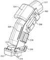
図3は、トラッキング装置302の一つの実施態様を示す略図である。トラッキング装置302は、一つまたは複数のコンポーネント、たとえばバッテリ304、電源コンポーネント306、アンテナ308、光学センサ310、レンズ312、セレクトスイッチ314、充電コンタクト316およびスクロールホイール318を含むことができる。トラッキング装置302は、ユーザの指317に配置されるように構成されることができる。特定の実施態様において、トラッキング装置302は、ユーザ317が指を挿入するハウジングを含むことができる。ハウジングは、ユーザの指317を定位置に保持するための一つまたは複数の保持機構を含むことができる。例示的な保持機構は、図4に関連してさらに詳細に説明する。 FIG. 3 is a schematic diagram illustrating one embodiment of the
特定の実施態様において、セレクトスイッチ314をトラッキング装置302の先端に加えることができる。セレクトスイッチ314は、いくつかの実施態様において、ユーザがユーザインタフェース上で項目を選択することを可能にする。たとえば、ユーザは、ウェブブラウザ中で表示されたハイパーリンク上にカーソルを配置し、セレクトスイッチ314をアクティブ化することによってそのハイパーリンクを選択することができる。セレクトスイッチ314は、ユーザがトラッキング装置302の先端に圧力を加えてそれを下に動かして隣接面に当てるならば、アクティブ化されることができる。特定の他の実施態様において、セレクトスイッチ314は、トラッキング装置302の中、光学センサ310の近くに配置されることができ、ユーザの指317と直接接触することができる。特定の他の実施態様において、セレクトスイッチ314は、トラッキング装置302の外に配置されることができる。たとえば、セレクトスイッチ314は、スクロールホイール318と一体化されることができる。 In certain embodiments, a
他の実施態様において、セレクトスイッチ314は、スイッチを前後方向または上下方向に押すことによってスクロールを達成することができるロッカスイッチを含むことができる。 In other embodiments, the
さらに他の実施態様において、セレクトスイッチは、加速度計を使用して具現化することもできる。たとえば、ユーザが表面を一回たたくと、加速度計がその動きを感知し、従来のマウスボタンによるシングルクリックと同様に選択を登録することができる。加速度計はまた、所定期間内の多数回の動きを検出することもできる。多数回の動き、たとえばユーザが表面を二回続けて素速くたたく動きは、ダブルクリック選択のような特定のタイプの選択を示すことができる。 In still other embodiments, the select switch can be implemented using an accelerometer. For example, when the user strikes the surface once, the accelerometer senses the movement and can register the selection in the same way as a single click with a conventional mouse button. The accelerometer can also detect multiple movements within a predetermined period. A number of movements, such as a user hitting the surface twice in quick succession, can indicate a particular type of selection, such as a double click selection.
特定の実施態様において、トラッキング装置302は、ベース202によって充電されることができる電源、たとえばバッテリ304を含むことができる。たとえば、トラッキング装置302は、トラッキング装置302がベース202に挿入されて充電コンタクト316がベース202と接触したとき、バッテリ304に充電することができる。さらには、電源コンポーネント306は、バッテリ304充電プロセスを制御することができる。いくつかの実施態様において、バッテリ304は、トラッキング装置のうち、ユーザの挿入された指よりも下に位置する部分の中に配置される。バッテリを指の下に配置すると、バッテリの重さをユーザの指の上に載せることなく、バッテリの重さを均衡させることになるため、この配置はトラッキング装置の人間工学性を改善することができる。 In certain implementations, the
先に述べたように、特定の実施態様において、トラッキング装置302は、コンピュータシステム102と通信するためのアンテナ308を含むことができる。たとえば、特定の実施態様において、アンテナ308は、トラッキング装置302の外部本体の内側に配置されるように構成されることができる。特定の他の実施態様において、アンテナ308は、トラッキング装置302の本体の外側に配置されるように構成されることもできる。アンテナ308は、データをコンピュータシステム102のレシーバに送信することができる。たとえば、アンテナ308は、動きデータ、バッテリ状態データ、入力データ、出力データ、スクロール選択データまたは他のタイプのデータをコンピュータシステム102のレシーバに送信することができる。特定の実施態様において、アンテナ308は、無線周波数(RF)プロトコルを使用して、データを、コンピュータシステム102のUSBポートに接続されたRFレシーバにワイヤレスで送信することができる。さらに他の実施態様において、トラッキング装置302はデータをベースに送信することができ、このベースが、ワイヤレスまたは有線接続を使用して、データをコンピュータシステム102に送信することができる。 As previously mentioned, in certain embodiments, the
特定の他の実施態様において、トラッキング装置302は、トラッキング装置302の動きを光学的にトラッキングするためのレンズ312を含むことができる。レンズ312は、たとえば、従来のコンピュータマウスに含まれるレンズと同様に、隣接面に赤外線を送ることができる。いくつかの実施態様において、レンズ312は、ガラスまたはプラスチック材料で構築されることができる。レンズ312はまた、たとえば、光学センサ310をくずまたは不要な接触から保護することもできる。 In certain other implementations, the
特定の実施態様において、トラッキング装置302は、レンズによって捕獲された動きを使用して動き情報を生成する光学センサ310を含むことができる。光学センサ310はまた、たとえば、コンピュータシステムによって使用されるための動き情報を送信することもできる。コンピュータシステム102は、送信された情報を使用してカーソルを駆動することができる。たとえば、光学センサ310は、赤外線技術を使用して、隣接面からの光の反射の変化をモニタリングすることによって動きをトラッキングすることができる。 In certain embodiments, the
いくつかの実施態様において、トラッキング機構、たとえば光学センサ310は、ユーザがユーザインタフェース上のオブジェクトを容易に操作することができるようなサイズである。たとえば、隣接面上での1インチ分のセンサの動きが、表示されたユーザインタフェース全体分の動きに対応することができる。トラッキング装置中のトラッキング機構は、1インチ分を容易かつ正確に動かすことができるような十分な小ささであることができる。 In some embodiments, the tracking mechanism, such as
他の実施態様において、センサ310は、動きをトラッキングするためのトラックボール、ローラボール、スクロールホイール、レーザベースのセンサまたは加速度計を含むことができる。動き変換コンポーネントは、別個に使用されることもできるし、これらまたは他の例示的コンポーネントとで併用されることもできる。 In other implementations, the
他の例示的な実施態様において、トラッキング装置302は、選択、入力または他のタイプの機能のためのさらなる方法を提供することができる、図3には示さないボタンを含むことができる。たとえば、一つの実施態様において、ボタンは、トラッキング装置302の外側で、ユーザの親指の近くに配置されることができる。特定の実施態様において、第一のボタンが選択機能を提供することができる。さらには、特定の実施態様において、第二のボタンがユーザインタフェースメニューの表示をプロンプトすることができる。たとえば、ウェブページ上の画像を閲覧しながら第二のボタンを選択すると、ウェブブラウザに対し、「名前を付けて画像を保存」、「背景に設定」、「プロパティ」などのオプションを含むメニューを表示するようプロンプトすることができる。 In other exemplary implementations, the
トラッキング装置302は、軽量プラスチック、ガラスファイバまたは他のタイプの材料などの様々な材料を使用して構築することができ、装置302は、様々な形状係数を使用して具現化することができる。たとえば、トラッキング装置は、ユーザの指317を囲い込むこともできるし、水分を逃がし、ユーザに快適さを提供することができる開口区域を前部、側部または後部に有することもできる。 The
図4は、ユーザの指を受け入れるために使用されるトラッキング装置104の指保持機構構造の一つの実施態様を示す略図である。いくつかの実施態様において、トラッキング装置104は、機械的手段を使用してユーザの指を受け入れるように構成されることができる。たとえば、トラッキング装置104は、ユーザの指をトラッキング装置104内で定位置に保持することを支援する可撓性タブ402を含むことができる。他の実施態様において、トラッキング装置104は内部スリーブ404を含むことができ、この内部スリーブが、トラッキング装置104をユーザの指の上で定位置に保持することを支援することができる。特定の実施態様において、スリーブ404は、多様なユーザに適合するために大小様々なサイズで提供されることができる。スリーブは、取り外すことができ、特定のユーザのためにフィットをカスタマイズするために、異なるサイズのスリーブを挿入することができる。 FIG. 4 is a schematic diagram illustrating one embodiment of the finger retention mechanism structure of the
図5は、ユーザの指を受け入れるために使用されるトラッキング装置104の構造の一つの実施態様を示す略図である。特定の実施態様において、トラッキング装置104は、指保持ヒンジコンポーネント502を含むように構成されることができる。保持コンポーネントは、たとえば、ネオプレン、サンプレンまたはフォームのような材料から製造されることができる。特定の実施態様において、ヒンジコンポーネントは、いくつかの位置または場所で構成されることができる。ユーザは、保持ヒンジコンポーネント502を含むことができるトラッキング装置104に指を挿入することができる。ひとたび挿入されると、保持ヒンジコンポーネント502は、圧力を加えることによってトラッキング装置104をユーザの指に保持することができる。特定の実施態様において、ヒンジコンポーネント502は、ゴムから製造されることができ、ヒンジコンポーネント502を指の周囲に押し付けるばねを含むことができる。 FIG. 5 is a schematic diagram illustrating one embodiment of the structure of the
他の実施態様において、トラッキング装置104は、指保持内部リングコンポーネントを含むことができる。例示的な実施態様において、リングは、ゲルに似た材料でできている。リングは、指の周囲に圧力を加えることにより、トラッキング装置104をユーザの挿入された指に固定することができる。リングが展性である(たとえばゲルでできている)ならば、リングはユーザの指の外面に適合することができ、それが、より快適なフィットを生じさせることができる。 In other implementations, the
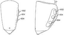
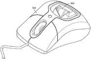
図6は、選択のために使用される装置コンポーネントの一つの実施態様を示す略図である。図6は、トラッキング装置104の正面図および側面図を示す。特定の実施態様において、トラッキング装置104は、コンピュータシステム上でのナビゲーションに使用することができるスクロールホイール602を含むことができる。他の実施態様において、トラッキング装置104は、コンピュータシステムによって表示される情報を選択するための一つまたは複数の選択ボタン604を含むことができる。 FIG. 6 is a schematic diagram illustrating one embodiment of device components used for selection. FIG. 6 shows a front view and a side view of the
図7は、トラッキング装置のスクロール構造のいくつかの実施態様を示す略図である。先に述べたように、トラッキング装置104は、コンピュータシステム上のカーソルの動きを制御するための様々なコンポーネントまたは構造で構成されることができる。特定の実施態様において、トラッキング装置104は、トラッキング装置が直立する位置に対してほぼ水平な面に向けられたスクロール機構および選択ボタンを含む。他の実施態様において、トラッキング装置104は、ほぼ垂直な面に向けられたスクロール機構および選択ボタンを含むことができる。他の実施態様において、トラッキング装置104は、水平な面に向けられたスクロール機構を含むことができ、スクロール機構に対して垂直に位置する選択ボタンを含むことができる。 FIG. 7 is a schematic diagram showing some embodiments of the scroll structure of the tracking device. As previously mentioned, the
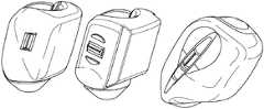
図8は、スクロール構造のいくつかのさらなる実施態様を示す略図である。特定の実施態様において、トラッキング装置104は、限られた数の方向にスクロールすることができるトラックボールコンポーネント802を含むことができる。たとえば、トラックボールコンポーネント802は、一つの方向またはその方向とは逆の方向にスクロールすることができる。 FIG. 8 is a schematic diagram showing some further embodiments of the scroll structure. In certain embodiments, the
他の実施態様において、トラッキング装置104は、多数の機能を有するトラックボールコンポーネント804を含むことができる。たとえば、トラックボールコンポーネントは、多数の方向にスクロールすることができ、ユーザは、トラックボールコンポーネント804を押して、ユーザインタフェースに表示されたオブジェクトの選択を行うことができる。 In other implementations, the
他の実施態様において、トラッキング装置104は、多数の方向にスクロールし、向けられることができるスクロール機構806を含むことができる。スクロール機構806の位置は、調節後、動き制限機構、たとえばスクロール機構804を包囲するスプラインのセットによって提供される抵抗を加えることにより、維持されることができる。たとえば、ユーザは、スクロール機構806を、ユーザにとって快適なスクロール位置である位置に調節することができる。スプラインの抵抗が、スクロール機構806がその位置から滑り出すことを防ぐ。 In other embodiments, the
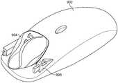
図9は、トラッキング装置がベース902の前部に受け入れられるベース902の実施態様を示す略図である。例示的な実施態様において、トラッキング装置904は、部分的にベース902の前部から外に突出して、ベース902からの取り出しのためにユーザの指が素速くアクセスすることができるように構成されることができる。もう一つの実施態様において、ベース902は、ベース902の中間または後部位置に配置することを要する他のコンポーネントを含むことができる。たとえば、ベース902は、ベース902の中間および後部位置の空間を占めるトラッキング機構コンポーネントを含むことができる。 FIG. 9 is a schematic diagram illustrating an embodiment of the base 902 in which a tracking device is received at the front of the
いくつかの実施態様において、ユーザがトラッキング装置904を取り外し、それをベース902の中に配置することを望むならば、ユーザは、トラッキング装置904をベース902のキャビティの中に配置することができ、ユーザは、指を後方に動かしてトラッキング装置904をベース902に固定することができる。いくつかの実施態様において、ベースは、トラッキング装置を定位置にパチンと嵌めるために使用される、突起のような固定コンポーネントを有する。ユーザがトラッキング装置904をベース902に固定したのち、ユーザは、トラッキング装置904から指を取り出すことができる。ユーザがトラッキング装置904をベース902から取り出すことを望むならば、ユーザは、指をトラッキング装置904の内側に配置し、指を前方に動かして、トラッキング装置を固定コンポーネントから解放することができる。 In some embodiments, if the user wishes to remove the
図10は、トラッキング装置がベースの中間部分で受け入れられるベースの第二の実施態様を示す略図である。ベース902は、トラッキング装置904をベース902の中間部分に受け入れるように具現化されることができ、それが、ベース902の前部または後部の場所における他のコンポーネントの配置を容易にする。たとえば、従来のコンピュータマウスとともに含まれるボタンに類似したボタンがベース902の前部に構成されてもよい。もう一つの例において、USBキー906がベース902中に格納されることができる。USBキー906は、たとえば、トラッキング装置904がベース902に挿入されているときトラッキング装置904とワイヤレスに通信するためにコンピュータシステムによって使用されることができる。ベース902は、他の方法を使用して(たとえば有線で)コンピュータシステムと通信することもできる。この状況において、ベースの前部または後部におけるUSBキー906の格納は、ベースがこれらの場所のいずれかでトラッキング装置904を受け入れることを妨げるため、ベースは、トラッキング装置を受け入れるためのキャビティを中間部分に含むことができる。 FIG. 10 is a schematic diagram showing a second embodiment of the base in which the tracking device is received in the middle part of the base.
図11は、トラッキング装置904がベース902の後部で受け入れられるベース902の第三の実施態様を示す略図である。この実施態様において、ベース902の後部にキャビティを形成して、たとえばベースが、ベースの後部に近いところよりもベースの前部に近いところでより小さい形状係数を有する場合、トラッキング装置がベース902の中に完全に嵌るようにすることができる。 FIG. 11 is a schematic diagram illustrating a third embodiment of the base 902 in which the
図9、図10および図11によって示されるように、ベース902は、多くの場所でトラッキング装置904を受け入れることができる。ベース902のもう一つの例示的な実施態様(図示せず)において、トラッキング装置は側面位置で受け入れられることができる。たとえば、トラッキング装置は、クリッピングまたはスナップ機構を使用して他のベースの側面に取り付けられる。特定の実施態様において、側面配置は、さらなるコンポーネントのための増大した内部空間をベース902内に提供することができる。他の実施態様において、側面配置は、ベース902がより小さな形状係数を有することを可能にすることができる。 As shown by FIGS. 9, 10 and 11, the base 902 can accept the
図12は、トラッキング装置904を受け入れるために使用されるベース902のふたカバー構造のいくつかの実施態様を示す略図である。ふた906は、ベース902内にトラッキング装置904を挿入するために開けることができる。特定の実施態様において、ふた906は、ユーザが押すとアクティブ化されることができる、ふたを開けるためのばね機構を含むことができる。さらには、ふた906は、トラッキング装置904をくずから保護するために、またはユーザの手にとってより快適なグリップを提供するために、閉じることができる。特定の実施態様において、ふた906は、含められたラッチ機構によって閉じた状態に保持されることができる。さらには、ふた906は、トラッキング装置904が挿入されるベースのキャビティへのアクセスを可能にするために、ベース902の一部分の中でスライドすることができる。他の実施態様において、ふた906は、取り外し、たとえばベース902の底に格納することもできる。 FIG. 12 is a schematic diagram illustrating some embodiments of a base 902 lid cover structure used to receive the
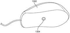
図13は、トラッキング装置904の隣接面へのアクセスを可能にする開口部1304を含むベース1302の一つの実施態様を示す略図である。特定の実施態様において、ベース1302は、ベース1302の底にある開口部1304を介して隣接面への光学部品、トラックボールまたはレーザのアクセスを可能にすることにより、トラッキング装置904のトラッキング機構を使用することができる。 FIG. 13 is a schematic diagram illustrating one embodiment of a base 1302 that includes an
特定の実施態様において、ベース1302は、トラッキング装置904のトラッキング機構を使用することができる。たとえば、ベース1302は、それ自体のトラッキング機構を動作不能にし、代わりに、トラッキング装置904のトラッキング機構を使用することができる。ベース1302は、トラッキング装置のトラッキング機構をベース1302に接続する回路を含むことができる。たとえば、ベースは、トラッキング装置904がベース1302に挿入されているときトラッキング装置904上のプレートと接触するプロングを含むことができる。トラッキング装置904は、この接続を介して動き情報をベース1302に送信することができる。いくつかの実施態様において、このベースへの接続はまた、ベースから印加されるまたは発生する電力を使用してトラッキング装置に充電するために使用することもできる。 In certain embodiments, the
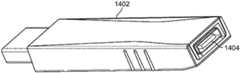
図14は、トラッキング装置1302からの情報をコンピュータシステム102に中継するために使用されるシステムの接続コンポーネント1402を示す略図である。いくつかの実施態様において、接続コンポーネント1402はUSBキーである。たとえば、ベース1502は、USBキー1402に接続するコードを含むことができる。USBキー1402とベース1502との間のインタフェースは、ユーザがベース1502を誤ったレセプタクル、たとえばコンピューティング装置上のPS-2ポートに入れてしまうことがないよう、専用のインタフェースであることができる。特定の実施態様において、コードは、ベース1502の中で巻き直されることもできるし、ベース1502の下に位置するキャビティの中に巻き取られ、格納されることもできる。 FIG. 14 is a schematic diagram illustrating a
特定の実施態様において、コードをベース1502から切り離すことができる。コードをベース1502から抜くと、たとえば、ベース1502をより簡便に格納することができる。他の実施態様において、ベース1502は、コードを有しなくてもよく、コンピュータシステム102とワイヤレスに通信する。 In certain embodiments, the cord can be disconnected from the
いくつかの実施態様において、トラッキング装置1302は、トラッキング装置1304がベース1502に挿入されているとき充電されるバッテリを有することができる。たとえば、ベースは、コンピュータシステム102へのコード式接続を介して電力を受けることができる。電力は、バッテリに充電するためにベースからトラッキング装置に伝送されることができる。他の実施態様において、ベースはコードで接続されず、その代わり、使い捨てまたは充電式のバッテリから電力を受ける。 In some implementations, the
いくつかの他の実施態様において、接続コンポーネント1402は、情報をコンピュータシステム102とで送受信することができる。たとえば、接続コンポーネント1402は、ベース装置(またはトラッキング装置)から情報を送受信し、その情報をコンピュータシステム102に送るワイヤレストランシーバであることができる。いくつかの実施態様において、トラッキング装置は情報をワイヤレスに送信することができ、ベース装置は、有線接続を介して情報をコンピュータシステム102に送信する。 In some other implementations, the
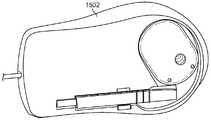
図15は、ベース格納構造の一つの実施態様の略図である。特定の実施態様において、USBキー1402をベース1502とともに格納する、またはそれに接続することができる。たとえば、USBキー1402は、ベース1502の底に格納することができ、その場合、ベース1502は、タブまたはクランプのような保持機構を含むことができる。上記機能性に加えて、特定の実施態様において、USBキーは、たとえば、トラッキング装置104のためのソフトウェアドライバまたはコンピュータシステム102によってアクセスすることができる他のデータファイルをはじめとする情報を記憶することができる。 FIG. 15 is a schematic diagram of one embodiment of a base storage structure. In certain embodiments, the
図16は、トラッキング装置104の代替実施態様を示す略図である。図16は、トラッキング装置がトラッキング装置104の先端のトラッキング機構なしで構成されている実施態様を示す。これは、ユーザの指1604を、たとえば可撓性クランプ機構1606を使用してユーザの指1604に保持されたトラッキング装置104の中に通すことを可能にすることができる。ユーザの指1604をトラッキング装置104の中に通すことを可能にすると、コンピュータキーボード上でのタイピングのような作業のために指を普通に使用することが可能になる。 FIG. 16 is a schematic diagram illustrating an alternative embodiment of the
図16のトラッキング装置はまた、多数の機能を有することができるトラックボールコンポーネント1602を含む。たとえば、トラックボールコンポーネント1602は、ユーザインタフェース上でカーソルをナビゲートしたり、スクロール機能を実行したりすることができる。さらには、ユーザは、トラックボールコンポーネント1602を押して(たとえば隣接する指を使用して)、ユーザインタフェースに表示されたオブジェクトの選択を行うことができる。 The tracking device of FIG. 16 also includes a
いくつかの実施態様において、トラッキング装置104は、装置の側面に光学センサを含むことができる。光学センサは、ユーザインタフェース制御、たとえばGUI上のカーソルを操作するために使用することができる。たとえば、ユーザは、トラッキング装置を人差し指の上に滑らすことができ、親指を使用して光学センサに触れることができる。光学センサは、センサ上のユーザの親指の動きを変換して、検出された動きにしたがってユーザインタフェース制御が操作されるようにすることができる。 In some implementations, the
いくつかの実施態様において、光学センサは、ユーザが親指(または指)をセンサから一定の距離内で動かしたのち、アクティブ化される。たとえば、センサは、オブジェクトが光学センサから一定の距離内にあるときそれを感知する赤外線トランシーバを含むことができる。オブジェクト(たとえば指または親指)がこの距離内で動くと、光学センサは、オブジェクトの動きを検出するために使用される光学部品をアクティブ化することができる。さらには、オブジェクトがこの距離の外に動くと、光学センサは光学部品を非アクティブ化することができる。 In some embodiments, the optical sensor is activated after the user moves the thumb (or finger) within a certain distance from the sensor. For example, the sensor can include an infrared transceiver that senses when an object is within a certain distance from the optical sensor. When an object (eg, a finger or thumb) moves within this distance, the optical sensor can activate an optical component that is used to detect the movement of the object. Furthermore, if the object moves out of this distance, the optical sensor can deactivate the optical component.
他の実施態様において、光学センサは、ユーザがセンサの上または近くに配置されたアクチュエータを押すと、アクティブ化される。たとえば、ユーザの親指がアクチュエータを押したときにレーザが光学センサから照射されて親指を避けて通過することも親指が防ぐよう、アクチュエータは光学センサのそばに配置されることもできる。さらに別の実施態様において、光学センサは、同じく光学センサの近くに配置されたスイッチにより、ユーザの親指がセンサ上に配置されたときスイッチが切り替えられて光学センサに給電するよう、アクティブ化される。 In other embodiments, the optical sensor is activated when the user presses an actuator located on or near the sensor. For example, the actuator can be placed beside the optical sensor so that when the user's thumb presses the actuator, the laser prevents the thumb from passing through the optical sensor and avoiding the thumb. In yet another embodiment, the optical sensor is activated by a switch, also located near the optical sensor, so that when the user's thumb is placed on the sensor, the switch is switched to power the optical sensor. .
ユーザが親指をはずすと、アクチュエータまたはスイッチが切り替えられて、光学センサが非アクティブ化されることができる(たとえば、回路がパワーダウンされる、レーザが放射されない、など)。 If the user removes the thumb, the actuator or switch can be switched to deactivate the optical sensor (eg, the circuit is powered down, the laser is not emitted, etc.).
いくつかの実施態様において、これは、ユーザがユーザ制御要素をアクティブに操作しようとしていないとき、装置による電力使用量を減らすことができる。さらには、これは、光学部品によって発される光がユーザの眼に入射しないよう、安全機構として働くこともできる。代わりに、光は、ユーザが光学センサを覆い隠してはじめて発され、それが他方で、発された任意の光がユーザの親指、他の指など以外の表面に照射されることを防ぐ。 In some implementations, this can reduce power usage by the device when the user is not actively manipulating the user control element. Furthermore, it can also act as a safety mechanism to prevent light emitted by the optical component from entering the user's eyes. Instead, light is emitted only when the user obscures the optical sensor, which, on the other hand, prevents any light emitted from illuminating surfaces other than the user's thumb, other fingers, and the like.
いくつかの実施態様において、他のナビゲーションハードウェア、たとえば前記ローラボール、スクロール機構などをも、装置の使用に基づいてアクティブ化または非アクティブ化することができる。たとえば、ローラボールは、所定の期間にわたり操作されなかったのち、非アクティブ化することができる。もう一つの例において、ローラボールは、使用前にユーザがローラボールを押すことによって「クリック」されてアクティブ化されることができる。ユーザは、終了すると、ローラボールを押してそれを非アクティブ化することができる。 In some embodiments, other navigation hardware, such as the roller ball, scroll mechanism, etc., can also be activated or deactivated based on the use of the device. For example, a roller ball can be deactivated after it has not been operated for a predetermined period of time. In another example, a roller ball can be “clicked” and activated by the user pressing the roller ball before use. When finished, the user can press the roller ball to deactivate it.
さらに他の実施態様において、トラッキング装置は、コンピュータ以外の装置と通信することもできる。たとえば、トラッキング装置は、消費者電子装置、たとえばステレオおよびテレビ、プリンタ、PDA、ガレージドアなどと通信することができる。たとえば、トラッキング装置は、出力および設定コマンドをテレビに送信することができる赤外線トランスミッタを含むことができる。たとえば、ユーザは、前述のLCDスクリーンおよび選択スイッチを使用してテレビの遠隔制御コードを入力することができる。そして、ユーザは、選択スイッチを使用してテレビへの赤外線コマンドの送信をアクティブ化することができる。同様に、トラッキング装置は、ガレージドアを制御するための無線周波数トランスミッタならびにたとえばプリンタ、携帯電話およびPDAと通信するためのブルートゥース回路を組み込むことができる。これらの例は、例を示すためのものであり、上記装置の用途を限定することを意図したものではない。 In still other embodiments, the tracking device can communicate with devices other than computers. For example, the tracking device can communicate with consumer electronic devices such as stereo and television, printers, PDAs, garage doors, and the like. For example, the tracking device can include an infrared transmitter that can send output and configuration commands to a television. For example, a user can enter a television remote control code using the LCD screen and selection switch described above. The user can then activate transmission of an infrared command to the television using the selection switch. Similarly, the tracking device can incorporate a radio frequency transmitter for controlling the garage door and a Bluetooth circuit for communicating with eg printers, cell phones and PDAs. These examples are for illustrative purposes and are not intended to limit the application of the device.
いくつかの実施態様を上記で詳細に説明したが、他の変形が可能である。たとえば、特定の実施態様において、トラッキング装置104は、情報をコンピュータシステムまたはトラッキング装置に入力する、またはそれから出力するためのLCD(液晶表示)コンポーネントを含むことができる。たとえば、LCDスクリーンは、トラッキング装置の「状態情報」、たとえば充電状態を表示することができる。いくつかの実施態様において、LCDスクリーンは、トラッキング装置104上、ユーザの親指に面する側のような場所またはユーザが表示装置を見ることができる他の場所に配置されることができる。 Although several embodiments have been described in detail above, other variations are possible. For example, in certain embodiments, the
他の実施態様において、トラッキング装置のうち、ユーザの指を受け入れる内寄り部分は、表面レリーフ構造、たとえばガス抜きリブ、チャネル、ディンプリングなどを含むことができる。これは、センサフィードバックをユーザに提供して、疲労を抑制し、発汗を制御し、熱を放出させることができる。さらには、内寄り部分は、トラッキング装置の先端に向けて狭まる円錐形を含むことができる。これは、トラッキング装置の狭まる内寄り部分に対する圧点および指摩擦の使用により、指の保持を保証することができる。 In other embodiments, the inboard portion of the tracking device that receives the user's finger can include a surface relief structure, such as a venting rib, channel, dimple ring, and the like. This can provide sensor feedback to the user to suppress fatigue, control sweating, and release heat. Further, the inward portion can include a conical shape that narrows toward the tip of the tracking device. This can ensure finger retention by the use of pressure points and finger friction on the narrowing inward portion of the tracking device.
さらに他の実施態様において、トラッキング装置のためのトラッキング機構(たとえば光学センサ)は、機構の傾斜が人間工学的になるように配置されることができる。たとえば、ユーザが指をトラッキング装置に挿入すると、光学センサは、自然な指の位置(たとえば静止位置)で隣接面に対して左右いずれにも傾かず、実質的に平行になるように装置上に配置される。 In still other embodiments, the tracking mechanism (eg, optical sensor) for the tracking device can be arranged such that the tilt of the mechanism is ergonomic. For example, when the user inserts a finger into the tracking device, the optical sensor is not tilted to the left or right with respect to the adjacent surface at the natural finger position (for example, a stationary position) and is substantially parallel to the device. Be placed.
他の実施態様において、装置のためのトラッキング機構はスイベル上に配置されて、トラッキング装置のユーザの配置がスイベルなしでトラッキング機構を実質的に平行な位置に配しないとしてもトラッキング機構が隣接面に対して実質的に平行な位置に動くことができるようにする。 In other embodiments, the tracking mechanism for the device is located on the swivel so that the tracking mechanism is adjacent to the surface even if the user's placement of the tracking device does not swivel and does not place the tracking mechanism in a substantially parallel position. It is possible to move to a substantially parallel position.
いくつかの実施態様において、ベースは、コンピューティング装置への接続を介してではなく家庭用電流を使用してトラッキング装置に充電することができる。たとえば、ベースのコードを家庭用電気アウトレットに挿入することができ、このアウトレットが、ベースに挿入されたトラッキング装置に電力を提供する。他の実施態様において、ベースは、トラッキング装置に充電するためのバッテリ(たとえば充電式バッテリ)を含むように構成されることができる。たとえば、バッテリは、ベースをUSBまたは標準的な電気アウトレットに差し込むことによって充電を受けることができる。そして、トラッキング装置がベースに挿入されると、トラッキング装置のバッテリをベースのバッテリによって充電することができる。他の実施態様において、トラッキング装置は、ベースとは別にある充電器に挿入または結合することができる。この充電器は、その電力を、家庭用電気アウトレット、バッテリまたはコンピュータの電源ユニット(たとえばUSB接続を介する)をはじめとする多様な電源から受けることができる。 In some implementations, the base can charge the tracking device using household current rather than via a connection to a computing device. For example, a base cord can be inserted into a household electrical outlet, which provides power to a tracking device inserted into the base. In other implementations, the base can be configured to include a battery (eg, a rechargeable battery) for charging the tracking device. For example, the battery can be charged by plugging the base into a USB or standard electrical outlet. When the tracking device is inserted into the base, the battery of the tracking device can be charged by the base battery. In other embodiments, the tracking device can be inserted or coupled to a charger that is separate from the base. The charger can receive its power from a variety of power sources including household electrical outlets, batteries or computer power supply units (eg, via a USB connection).
いくつかの実施態様において、ベースは、クランプ機構を使用してラップトップコンピュータまたはキーボードの側面に固定することができる。クランプ機構の一端は、キーボードまたはラップトップコンピュータに付くように構成されることができ、クランプ機構の他端はベースを固定することができる。たとえば、クランプ機構は、万力状の機構を使用してキーボードの側面にクランプすることができる。 In some embodiments, the base can be secured to the side of a laptop computer or keyboard using a clamping mechanism. One end of the clamp mechanism can be configured to attach to a keyboard or laptop computer, and the other end of the clamp mechanism can secure the base. For example, the clamping mechanism can be clamped to the side of the keyboard using a vise-like mechanism.
いくつかの実施態様において、クランプ機構は、嵌め込み接続を使用してベースに接続することができる。たとえば、プロングが、クランプ機構から外に延び、ベース中のポートと嵌り合うことができる。いくつかの実施態様において、プロングは、可撓性プラスチックまたは何らかのタイプのフックであることができる。 In some embodiments, the clamping mechanism can be connected to the base using a snap-fit connection. For example, a prong can extend out of the clamping mechanism and mate with a port in the base. In some embodiments, the prongs can be flexible plastic or some type of hook.
いくつかの実施態様において、ベースは、トラッキング装置以外のさらなるコンポーネント、たとえばふたおよびUSBキーを収容するのに十分な大きさであることができる。たとえば、ふたおよびUSBキーは、ベースの底に格納することができる。 In some implementations, the base can be large enough to accommodate additional components other than the tracking device, such as a lid and a USB key. For example, the lid and USB key can be stored on the bottom of the base.
いくつかの実施態様において、ベースは、トラッキング装置の充電状態を示すための発光ダイオード(LED)を含むことができる。ベース中の充電式バッテリのオプションが含まれるならば、たとえばその充電状態を示すためのLEDを含めることもできる。 In some implementations, the base can include a light emitting diode (LED) to indicate the state of charge of the tracking device. If an option for a rechargeable battery in the base is included, for example, an LED can be included to indicate its charge status.
他の実施態様において、USBキーは、コンピュータUSBスロットに挿入されることができ、コードを介してベースに接続されている間、トラッキング装置とワイヤレスに通信することができる。また、トラッキング装置およびベースは、コードを使用せずに、コンピュータとワイヤレスに通信するように構成されることもできる。 In other embodiments, the USB key can be inserted into a computer USB slot and can communicate wirelessly with the tracking device while connected to the base via a cord. The tracking device and base can also be configured to communicate wirelessly with a computer without using a code.
いくつかの実施態様において、ホルダコンポーネントを使用してトラッキング装置を保持することができる。ホルダコンポーネントは、ベースから独立して使用することができる。ホルダは、クランプ、クリップまたは他の様々な固定機構を使用してキーボード、コンピュータ表示装置またはコンピューティング装置に取り付けることができる。いくつかの実施態様において、ホルダは、充電タブおよび充電のためにUSBポートまたはUSBキーに接続するコードを含むことができる。もう一つの実施態様において、ベースのコードは、電力を受けるために家庭用アウトレットに接続することができる。 In some embodiments, a holder component can be used to hold the tracking device. The holder component can be used independently of the base. The holder can be attached to a keyboard, computer display or computing device using clamps, clips or various other securing mechanisms. In some implementations, the holder can include a charging tab and a cord that connects to a USB port or USB key for charging. In another embodiment, the base cord can be connected to a household outlet to receive power.
さらに別の実施態様において、第二のトラッキング装置を第一のトラッキング装置とともに使用して、一つまたは複数のユーザインタフェース要素を制御することができる。たとえば、トラッキング装置は、ユーザの各手の一つの指に装着することができる。この例において、ユーザは、トラッキング装置に固定された両方の指を回転させることにより、トラッキング装置を使用してインタフェースオブジェクト、たとえば三次元オブジェクトを操作することができる。他の例においては、トラッキング装置を使用してビデオゲーム中のオブジェクトを操作することができ、たとえば、一つの指を第一のトラッキング装置とともに動かして第一のキャラクタ動作を生じさせ、第二の指をもう一つのトラッキング装置とともに動かして第二のキャラクタ動作を生じさせ、第一および第二の指を同時に動かして第三のキャラクタ動作を生じさせる。 In yet another embodiment, a second tracking device can be used with the first tracking device to control one or more user interface elements. For example, the tracking device can be worn on one finger of each hand of the user. In this example, the user can manipulate an interface object, for example a three-dimensional object, using the tracking device by rotating both fingers fixed on the tracking device. In other examples, the tracking device can be used to manipulate an object in the video game, for example, one finger moves with the first tracking device to cause a first character action, A finger is moved with another tracking device to produce a second character action, and the first and second fingers are moved simultaneously to produce a third character action.
さらに他の例において、各手の指にトラッキング装置を有するユーザは、各トラッキング装置上の選択ボタンを使用して、表示されるオブジェクト、たとえばビデオゲームキャラクタを操作することができる。 In yet another example, a user having a tracking device on each finger of a hand can use a selection button on each tracking device to manipulate an object being displayed, such as a video game character.
特定の実施態様において、ベース装置のためのコードは、非標準USB接続を使用してUSBキーに接続する。これは、ユーザが不注意からベース装置をコンピュータ上のUSBポートに直接差し込むことを防ぐことができる。 In certain embodiments, the code for the base device connects to the USB key using a non-standard USB connection. This can prevent the user from inadvertently plugging the base device directly into a USB port on the computer.
したがって、他の実施態様が以下の特許請求の範囲に入る。 Accordingly, other embodiments are within the scope of the following claims.
Claims (29)
Translated fromJapanese該ユーザインタフェースオブジェクトを動かす際に使用するための隣接面に対する動きを変換するように構成されている、該トラッキング装置を受け入れるように構成されたベース装置と
を含む、コンピュータ周辺システム。A tracking device for generating motion information for use in moving a user interface object on a graphical user interface configured to accept at least a portion of a user's finger and used in moving the user interface object And a base device configured to receive the tracking device, the computer peripheral system being configured to convert motion relative to an adjacent surface to perform.
該トラッキング装置が、ユーザインタフェース上でユーザインタフェースオブジェクトを動かす際に使用するための動き情報を生成し、
該ベース装置が、該ユーザインタフェースオブジェクトを動かす際に使用するための隣接面に対する該ベース装置の動きを変換するように構成されている、
機器。A base device for receiving a tracking device configured to be placed on a user's finger;
The tracking device generates motion information for use in moving a user interface object on the user interface;
The base device is configured to translate movement of the base device relative to an adjacent surface for use in moving the user interface object;
machine.
表示装置上で第一のユーザインタフェースオブジェクトを動かすように構成されている動き情報を、隣接面に対する該ハウジングの動きに基づいて生成するための動きトラッカと、
該隣接面に押し当てられると該表示装置上の第二のユーザインタフェースオブジェクトの選択を行うように構成され、かつ該ハウジングに結合された感圧スイッチと
を含む、機器。A housing having a finger holding portion configured to receive a portion of a user's finger;
A motion tracker for generating motion information configured to move the first user interface object on the display device based on the movement of the housing relative to the adjacent surface;
A pressure sensitive switch configured to select a second user interface object on the display device when pressed against the adjacent surface and coupled to the housing.
Applications Claiming Priority (2)
| Application Number | Priority Date | Filing Date | Title |
|---|---|---|---|
| US11/754,071US8648805B2 (en) | 2004-11-05 | 2007-05-25 | Fingertip mouse and base |
| PCT/US2008/064764WO2008148043A2 (en) | 2007-05-25 | 2008-05-23 | Fingertip mouse and base |
Publications (2)
| Publication Number | Publication Date |
|---|---|
| JP2010528397Atrue JP2010528397A (en) | 2010-08-19 |
| JP2010528397A5 JP2010528397A5 (en) | 2011-07-07 |
Family
ID=40075750
Family Applications (1)
| Application Number | Title | Priority Date | Filing Date |
|---|---|---|---|
| JP2010510443APendingJP2010528397A (en) | 2007-05-25 | 2008-05-23 | Fingertip mouse and base |
Country Status (6)
| Country | Link |
|---|---|
| US (4) | US8648805B2 (en) |
| EP (1) | EP2156273A2 (en) |
| JP (1) | JP2010528397A (en) |
| AU (1) | AU2008256714A1 (en) |
| CA (1) | CA2688320A1 (en) |
| WO (1) | WO2008148043A2 (en) |
Cited By (1)
| Publication number | Priority date | Publication date | Assignee | Title |
|---|---|---|---|---|
| JP2013012174A (en)* | 2011-06-29 | 2013-01-17 | Giga-Byte Technology Co Ltd | Pointer device |
Families Citing this family (19)
| Publication number | Priority date | Publication date | Assignee | Title |
|---|---|---|---|---|
| US8648805B2 (en) | 2004-11-05 | 2014-02-11 | Ftm Computer Products | Fingertip mouse and base |
| US20110216004A1 (en)* | 2010-03-08 | 2011-09-08 | David Stephenson | Tilt and position command system for input peripherals |
| US20160259433A1 (en) | 2008-11-14 | 2016-09-08 | David Stephenson | Tilt and position command system for input peripherals |
| US8717291B2 (en)* | 2009-10-07 | 2014-05-06 | AFA Micro Co. | Motion sensitive gesture device |
| US8681101B1 (en)* | 2011-03-17 | 2014-03-25 | Daniel Haney | Finger mounted input device |
| US20120242618A1 (en)* | 2011-03-25 | 2012-09-27 | Everest John | Finger device for operating a capacitive touch screen |
| US9891718B2 (en) | 2015-04-22 | 2018-02-13 | Medibotics Llc | Devices for measuring finger motion and recognizing hand gestures |
| KR101667179B1 (en)* | 2013-05-30 | 2016-10-17 | 호메이윤 카제루니 | User-coupled human-machine interface system and a control method of an exoskeleton thereof |
| US9625884B1 (en)* | 2013-06-10 | 2017-04-18 | Timothy Harris Ousley | Apparatus for extending control and methods thereof |
| TWI492104B (en)* | 2013-06-20 | 2015-07-11 | Pixart Imaging Inc | Optical mini-mouse |
| US9652052B2 (en) | 2013-06-20 | 2017-05-16 | Pixart Imaging Inc. | Optical mini-mouse |
| US9958529B2 (en) | 2014-04-10 | 2018-05-01 | Massachusetts Institute Of Technology | Radio frequency localization |
| TWD171525S (en)* | 2014-06-24 | 2015-11-01 | 鴻海精密工業股份有限公司 | Ring reader |
| JP6372266B2 (en)* | 2014-09-09 | 2018-08-15 | ソニー株式会社 | Projection type display device and function control method |
| US9798387B2 (en)* | 2016-01-18 | 2017-10-24 | Anoop Molly JOSEPH | Multipurpose computer mouse |
| RU2630165C2 (en)* | 2016-03-17 | 2017-09-05 | Немнюгин Андрей Юрьевич | Compact pointing device "mouse" |
| RU2659592C2 (en)* | 2017-01-10 | 2018-07-03 | Немнюгин Андрей Юрьевич | Mouse - personal computer pointing device |
| CN109840023A (en)* | 2017-11-24 | 2019-06-04 | 南宁市远才教育咨询有限公司 | A kind of mouse on finger tip |
| US11307680B2 (en)* | 2020-02-12 | 2022-04-19 | Smash Engineering Inc. | Computer mouse adapter and associated methods |
Citations (11)
| Publication number | Priority date | Publication date | Assignee | Title |
|---|---|---|---|---|
| JPH04270408A (en)* | 1991-02-26 | 1992-09-25 | Oki Electric Ind Co Ltd | Pointing device |
| US5706026A (en)* | 1993-01-25 | 1998-01-06 | Kent; Robert Hormann | Finger operated digital input device |
| JPH10301706A (en)* | 1997-04-24 | 1998-11-13 | Nec Niigata Ltd | Mounting type pointing device |
| US6043807A (en)* | 1997-09-23 | 2000-03-28 | At&T Corp. | Mouse for positioning a cursor on a computer display and having a removable pen-type input device |
| JP2000330722A (en)* | 1999-05-21 | 2000-11-30 | Alps Electric Co Ltd | Device for inputting position information |
| JP2001202194A (en)* | 2000-01-20 | 2001-07-27 | Moyo Gi | Mouse |
| JP2003029924A (en)* | 2001-07-17 | 2003-01-31 | Yoshitomo Suga | Mouse |
| WO2003049020A1 (en)* | 2001-12-06 | 2003-06-12 | Digityper Ab | Pointing device |
| JP2003186615A (en)* | 2001-12-20 | 2003-07-04 | Canon Inc | Pen type coordinate input device |
| JP3117814U (en)* | 2005-04-26 | 2006-01-12 | シェンツェン インシー エレクトロニック リミテッド カンパニー | Wireless mouse that can hold a USB receiver |
| JP2006164275A (en)* | 2004-11-30 | 2006-06-22 | Microsoft Corp | System and directional input device for displaying images in a plurality of directions |
Family Cites Families (58)
| Publication number | Priority date | Publication date | Assignee | Title |
|---|---|---|---|---|
| US4780707A (en) | 1985-07-18 | 1988-10-25 | Selker Edwin J | Analog input device for a computer |
| US4954817A (en) | 1988-05-02 | 1990-09-04 | Levine Neil A | Finger worn graphic interface device |
| GB8914235D0 (en) | 1989-06-21 | 1989-08-09 | Tait David A G | Finger operable control devices |
| JPH03117814A (en) | 1989-09-29 | 1991-05-20 | Toshiba Corp | Gas interrupting device |
| US5444462A (en) | 1991-12-16 | 1995-08-22 | Wambach; Mark L. | Computer mouse glove with remote communication |
| US5220690A (en) | 1992-06-19 | 1993-06-22 | Hoos Barbara J | Thumb guard novelty device |
| JP3117814B2 (en) | 1992-11-06 | 2000-12-18 | 株式会社東芝 | Automatic recharge lighting device |
| EP0606704B1 (en) | 1993-01-12 | 1999-04-14 | Lee S. Weinblatt | Finger-mounted computer interface device |
| US5355148A (en) | 1993-01-14 | 1994-10-11 | Ast Research, Inc. | Fingerpoint mouse |
| US5453759A (en) | 1993-07-28 | 1995-09-26 | Seebach; Jurgen | Pointing device for communication with computer systems |
| US5563628A (en) | 1993-10-12 | 1996-10-08 | Stroop; Jeffrey A. | Hand held computer cursor controller and command input device |
| US5489922A (en) | 1993-12-08 | 1996-02-06 | Hewlett-Packard Company | Hand worn remote computer mouse |
| US5581484A (en) | 1994-06-27 | 1996-12-03 | Prince; Kevin R. | Finger mounted computer input device |
| US5894303A (en) | 1995-03-14 | 1999-04-13 | Barr; Ann E. | Computer mouse and shell therefore |
| US5627348A (en) | 1995-04-07 | 1997-05-06 | A.T. Cross Company | Electronic stylus with writing feel |
| US5999166A (en) | 1996-04-09 | 1999-12-07 | Rangan; Karur S. | Apparatus and method for optically modulating electronic signals and computer data |
| US5764164A (en) | 1997-02-07 | 1998-06-09 | Reality Quest Corp. | Ergonomic hand-attachable controller |
| US5796354A (en) | 1997-02-07 | 1998-08-18 | Reality Quest Corp. | Hand-attachable controller with direction sensing |
| US5886685A (en) | 1997-04-08 | 1999-03-23 | Best; Eddie L. | Foot operated computer mouse adaptor |
| US5990870A (en) | 1997-09-09 | 1999-11-23 | Chen; Mei-Yun | Finger rest structure of computer mouse |
| JP4011165B2 (en) | 1997-11-21 | 2007-11-21 | 泰和 楊 | Mouse with handle |
| US6098886A (en) | 1998-01-21 | 2000-08-08 | Symbol Technologies, Inc. | Glove-mounted system for reading bar code symbols |
| US6034627A (en) | 1998-02-19 | 2000-03-07 | Wei; Meng-Yu | Computer input device |
| US6154199A (en) | 1998-04-15 | 2000-11-28 | Butler; Craig L. | Hand positioned mouse |
| US6462732B2 (en) | 1999-07-28 | 2002-10-08 | Michael Mehr | Hand un-inhibiting cursor control device |
| US6580420B1 (en) | 2000-03-15 | 2003-06-17 | Yanqing Wang | Convertible computer input device |
| US6590563B1 (en) | 2000-07-21 | 2003-07-08 | Hewlett-Packard Development Company, L.P. | Pointing device having two parts and method of use therefor |
| US20020056009A1 (en) | 2000-08-22 | 2002-05-09 | Affif Filippo L. | Method for interacting with a device using an abstract space |
| US6587090B1 (en) | 2000-10-03 | 2003-07-01 | Eli D. Jarra | Finger securable computer input device |
| EP1197915A1 (en) | 2000-10-13 | 2002-04-17 | Matthew Hercules Robinson | computer mouse |
| US20020067342A1 (en) | 2000-12-05 | 2002-06-06 | Proper Kenneth W. | Computer mouse |
| US20020101401A1 (en) | 2001-01-29 | 2002-08-01 | Mehran Movahed | Thumb mounted function and cursor control device for a computer |
| US7133021B2 (en) | 2001-06-09 | 2006-11-07 | Coghan Iv Francis F | Finger-fitting pointing device |
| US20030006962A1 (en) | 2001-07-06 | 2003-01-09 | Bajramovic Mark B. | Computer mouse on a glove |
| US7737942B2 (en) | 2001-07-06 | 2010-06-15 | Bajramovic Mark B | Computer mouse on a glove |
| EP1282018A1 (en) | 2001-08-03 | 2003-02-05 | Nokia Corporation | A wearable electronic device |
| US6850224B2 (en)* | 2001-08-27 | 2005-02-01 | Carba Fire Technologies, Inc. | Wearable ergonomic computer mouse |
| US20030071787A1 (en)* | 2001-10-12 | 2003-04-17 | Gerstacker Stuart Thomas | Foot actuated computer mouse adaptor and electronic modular adaptor |
| CA2372268A1 (en) | 2002-02-15 | 2003-08-15 | John N. A. Brown | Finger operated digital input device |
| US20030174124A1 (en) | 2002-03-12 | 2003-09-18 | Hoton How | Method and apparatus of obtaining mouse operation at finger tip |
| US6985755B2 (en) | 2002-04-17 | 2006-01-10 | Broadcom Corporation | Reduced power consumption wireless interface device |
| US7081883B2 (en)* | 2002-05-14 | 2006-07-25 | Michael Changcheng Chen | Low-profile multi-channel input device |
| US20030214481A1 (en)* | 2002-05-14 | 2003-11-20 | Yongming Xiong | Finger worn and operated input device and method of use |
| US20030227437A1 (en) | 2002-06-05 | 2003-12-11 | Ramirez Nohl W. | Computer pointing device and utilization system |
| US20040080493A1 (en) | 2002-10-25 | 2004-04-29 | Shahar Kenin | Index-finger computer mouse |
| SE0203461D0 (en) | 2002-11-22 | 2002-11-22 | Digityper Ab | Dual-mode pointing device and detachable casing |
| CN1206585C (en)* | 2003-01-06 | 2005-06-15 | 致伸科技股份有限公司 | Dual-Purpose input device |
| US7048183B2 (en)* | 2003-06-19 | 2006-05-23 | Scriptpro Llc | RFID rag and method of user verification |
| US7042438B2 (en)* | 2003-09-06 | 2006-05-09 | Mcrae Michael William | Hand manipulated data apparatus for computers and video games |
| JP4773060B2 (en)* | 2004-04-20 | 2011-09-14 | 富士通コンポーネント株式会社 | Cordless pointing device apparatus and information terminal apparatus |
| US20060012567A1 (en)* | 2004-07-13 | 2006-01-19 | Todd Sicklinger | Minature optical mouse and stylus |
| US7151357B2 (en) | 2004-07-30 | 2006-12-19 | Kye Systems Corporation | Pulse frequency modulation for induction charge device |
| US20060079276A1 (en) | 2004-10-07 | 2006-04-13 | Auraham (Avi) Indik | Combination wireless mouse/mobile telephone system |
| CN2738325Y (en) | 2004-10-15 | 2005-11-02 | 段西京 | Photoelectrical pen type mouse |
| ES1058782Y (en) | 2004-10-29 | 2005-05-16 | Lluch Frco Javier Amat | MOUSE FOR COMPUTER EQUIPMENT. |
| US8648805B2 (en) | 2004-11-05 | 2014-02-11 | Ftm Computer Products | Fingertip mouse and base |
| JP2008191712A (en)* | 2007-01-31 | 2008-08-21 | Canon Inc | Image processing apparatus, image processing method, and program |
| US8031172B2 (en)* | 2007-10-12 | 2011-10-04 | Immersion Corporation | Method and apparatus for wearable remote interface device |
- 2007
- 2007-05-25USUS11/754,071patent/US8648805B2/enactiveActive
- 2008
- 2008-05-23JPJP2010510443Apatent/JP2010528397A/enactivePending
- 2008-05-23AUAU2008256714Apatent/AU2008256714A1/ennot_activeAbandoned
- 2008-05-23WOPCT/US2008/064764patent/WO2008148043A2/enactiveApplication Filing
- 2008-05-23EPEP08756239Apatent/EP2156273A2/ennot_activeWithdrawn
- 2008-05-23CACA002688320Apatent/CA2688320A1/ennot_activeAbandoned
- 2014
- 2014-02-06USUS14/174,483patent/US9261983B2/enactiveActive
- 2015
- 2015-01-08USUS14/592,475patent/US9092075B2/enactiveActive
- 2016
- 2016-02-05USUS15/016,567patent/US10963070B2/enactiveActive
Patent Citations (11)
| Publication number | Priority date | Publication date | Assignee | Title |
|---|---|---|---|---|
| JPH04270408A (en)* | 1991-02-26 | 1992-09-25 | Oki Electric Ind Co Ltd | Pointing device |
| US5706026A (en)* | 1993-01-25 | 1998-01-06 | Kent; Robert Hormann | Finger operated digital input device |
| JPH10301706A (en)* | 1997-04-24 | 1998-11-13 | Nec Niigata Ltd | Mounting type pointing device |
| US6043807A (en)* | 1997-09-23 | 2000-03-28 | At&T Corp. | Mouse for positioning a cursor on a computer display and having a removable pen-type input device |
| JP2000330722A (en)* | 1999-05-21 | 2000-11-30 | Alps Electric Co Ltd | Device for inputting position information |
| JP2001202194A (en)* | 2000-01-20 | 2001-07-27 | Moyo Gi | Mouse |
| JP2003029924A (en)* | 2001-07-17 | 2003-01-31 | Yoshitomo Suga | Mouse |
| WO2003049020A1 (en)* | 2001-12-06 | 2003-06-12 | Digityper Ab | Pointing device |
| JP2003186615A (en)* | 2001-12-20 | 2003-07-04 | Canon Inc | Pen type coordinate input device |
| JP2006164275A (en)* | 2004-11-30 | 2006-06-22 | Microsoft Corp | System and directional input device for displaying images in a plurality of directions |
| JP3117814U (en)* | 2005-04-26 | 2006-01-12 | シェンツェン インシー エレクトロニック リミテッド カンパニー | Wireless mouse that can hold a USB receiver |
Cited By (1)
| Publication number | Priority date | Publication date | Assignee | Title |
|---|---|---|---|---|
| JP2013012174A (en)* | 2011-06-29 | 2013-01-17 | Giga-Byte Technology Co Ltd | Pointer device |
Also Published As
| Publication number | Publication date |
|---|---|
| US10963070B2 (en) | 2021-03-30 |
| US20160154483A1 (en) | 2016-06-02 |
| US20090213077A1 (en) | 2009-08-27 |
| WO2008148043A3 (en) | 2009-06-11 |
| WO2008148043A2 (en) | 2008-12-04 |
| AU2008256714A1 (en) | 2008-12-04 |
| US20140292656A1 (en) | 2014-10-02 |
| EP2156273A2 (en) | 2010-02-24 |
| US20150123905A1 (en) | 2015-05-07 |
| US9261983B2 (en) | 2016-02-16 |
| US8648805B2 (en) | 2014-02-11 |
| US9092075B2 (en) | 2015-07-28 |
| CA2688320A1 (en) | 2008-12-04 |
Similar Documents
| Publication | Publication Date | Title |
|---|---|---|
| JP2010528397A (en) | Fingertip mouse and base | |
| CN105473021B (en) | wearable device and related system | |
| JP4099450B2 (en) | Gloves computer mouse | |
| US8217893B2 (en) | Inertial sensor-based pointing device with removable transceiver | |
| CN107003750B (en) | Multi-surface controller | |
| US9122456B2 (en) | Enhanced detachable sensory-interface device for a wireless personal communication device and method | |
| US7042438B2 (en) | Hand manipulated data apparatus for computers and video games | |
| US20110210931A1 (en) | Finger-worn device and interaction methods and communication methods | |
| US8363012B2 (en) | Pointing device for interface with a graphical display | |
| KR102053367B1 (en) | Wearable Interface Device | |
| WO2013163233A1 (en) | Detachable sensory-interface device for a wireless personal communication device and method | |
| US12026325B2 (en) | Handheld input devices with sleeves | |
| KR101625066B1 (en) | Wearable mouse | |
| US20240329754A1 (en) | Wearable keyboard for electronic devices | |
| US12259560B2 (en) | Handheld controllers with charging and storage systems | |
| WO2024205599A1 (en) | Wearable keyboard for electronic devices | |
| KR101373182B1 (en) | A portable computer including a pointing device capable of detaching | |
| KR101840201B1 (en) | Mouse | |
| KR20250137566A (en) | portable controller | |
| KR20140134454A (en) | Protective case having function of operating portable terminal | |
| TW201117059A (en) | Pointing device and notebook using the same |
Legal Events
| Date | Code | Title | Description |
|---|---|---|---|
| A521 | Request for written amendment filed | Free format text:JAPANESE INTERMEDIATE CODE: A523 Effective date:20110520 | |
| A621 | Written request for application examination | Free format text:JAPANESE INTERMEDIATE CODE: A621 Effective date:20110520 | |
| A521 | Request for written amendment filed | Free format text:JAPANESE INTERMEDIATE CODE: A523 Effective date:20120521 | |
| A977 | Report on retrieval | Free format text:JAPANESE INTERMEDIATE CODE: A971007 Effective date:20121219 | |
| A131 | Notification of reasons for refusal | Free format text:JAPANESE INTERMEDIATE CODE: A131 Effective date:20121227 | |
| A601 | Written request for extension of time | Free format text:JAPANESE INTERMEDIATE CODE: A601 Effective date:20130326 | |
| A602 | Written permission of extension of time | Free format text:JAPANESE INTERMEDIATE CODE: A602 Effective date:20130402 | |
| A02 | Decision of refusal | Free format text:JAPANESE INTERMEDIATE CODE: A02 Effective date:20130821 |