JP2010528313A - Encoder and method for accurately indicating position - Google Patents
Encoder and method for accurately indicating positionDownload PDFInfo
- Publication number
- JP2010528313A JP2010528313AJP2010509947AJP2010509947AJP2010528313AJP 2010528313 AJP2010528313 AJP 2010528313AJP 2010509947 AJP2010509947 AJP 2010509947AJP 2010509947 AJP2010509947 AJP 2010509947AJP 2010528313 AJP2010528313 AJP 2010528313A
- Authority
- JP
- Japan
- Prior art keywords
- track
- optical
- sensors
- encoder
- machine
- Prior art date
- Legal status (The legal status is an assumption and is not a legal conclusion. Google has not performed a legal analysis and makes no representation as to the accuracy of the status listed.)
- Granted
Links
- 238000000034methodMethods0.000titleclaimsabstractdescription11
- 230000003287optical effectEffects0.000claimsdescription94
- 230000008859changeEffects0.000claimsdescription3
- 239000000758substrateSubstances0.000claims1
- 230000008901benefitEffects0.000description6
- 238000004519manufacturing processMethods0.000description5
- 230000009467reductionEffects0.000description4
- 238000004590computer programMethods0.000description3
- 238000013459approachMethods0.000description2
- 230000003247decreasing effectEffects0.000description2
- 238000010586diagramMethods0.000description2
- 238000012986modificationMethods0.000description2
- 230000004048modificationEffects0.000description2
- 230000005693optoelectronicsEffects0.000description2
- 238000011000absolute methodMethods0.000description1
- 238000003491arrayMethods0.000description1
- 238000007796conventional methodMethods0.000description1
- 238000011161developmentMethods0.000description1
- 230000007246mechanismEffects0.000description1
- 238000005457optimizationMethods0.000description1
- 230000000737periodic effectEffects0.000description1
Images


Classifications
- G—PHYSICS
- G01—MEASURING; TESTING
- G01D—MEASURING NOT SPECIALLY ADAPTED FOR A SPECIFIC VARIABLE; ARRANGEMENTS FOR MEASURING TWO OR MORE VARIABLES NOT COVERED IN A SINGLE OTHER SUBCLASS; TARIFF METERING APPARATUS; MEASURING OR TESTING NOT OTHERWISE PROVIDED FOR
- G01D5/00—Mechanical means for transferring the output of a sensing member; Means for converting the output of a sensing member to another variable where the form or nature of the sensing member does not constrain the means for converting; Transducers not specially adapted for a specific variable
- G01D5/12—Mechanical means for transferring the output of a sensing member; Means for converting the output of a sensing member to another variable where the form or nature of the sensing member does not constrain the means for converting; Transducers not specially adapted for a specific variable using electric or magnetic means
- G01D5/244—Mechanical means for transferring the output of a sensing member; Means for converting the output of a sensing member to another variable where the form or nature of the sensing member does not constrain the means for converting; Transducers not specially adapted for a specific variable using electric or magnetic means influencing characteristics of pulses or pulse trains; generating pulses or pulse trains
- G01D5/249—Mechanical means for transferring the output of a sensing member; Means for converting the output of a sensing member to another variable where the form or nature of the sensing member does not constrain the means for converting; Transducers not specially adapted for a specific variable using electric or magnetic means influencing characteristics of pulses or pulse trains; generating pulses or pulse trains using pulse code
- G01D5/2492—Pulse stream
Landscapes
- Physics & Mathematics (AREA)
- General Physics & Mathematics (AREA)
- Optical Transform (AREA)
- Transmission And Conversion Of Sensor Element Output (AREA)
Abstract
Translated fromJapaneseDescription
Translated fromJapanese本発明は第1の部材の位置を第2の部材に関して正確に示すエンコーダおよび方法に関する。本発明は、特に光学式エンコーダのため有用であるので、以下ではこのような用途に関して記載されているが、本発明はブラシ・アンド・スリップリング式エンコーダおよび磁気式エンコーダのような非光学式エンコーダに関しても使用できることが理解されるであろう。 The present invention relates to an encoder and method for accurately indicating the position of a first member with respect to a second member. Since the present invention is particularly useful for optical encoders, it will be described below with respect to such applications, but the present invention is non-optical encoders such as brush and slip ring encoders and magnetic encoders. It will be understood that can also be used.
一般的なタイプのエンコーダは、可動部材、たとえば、回転軸または直動部材に連結され、可動部材の位置に関する情報、すなわち、軸の回転角度または直動部材の直線位置を提供するために処理され得る電気信号を生成できる電気機械装置である。 A common type of encoder is coupled to a movable member, such as a rotating shaft or linear member, and is processed to provide information about the position of the movable member, i.e., the rotational angle of the shaft or the linear position of the linear member. An electromechanical device capable of generating an electrical signal to be obtained.
エンコーダはインクリメンタル方式でもよく、アブソリュート方式でもよい。インクリメンタルエンコーダは、初期位置、すなわち、エンコーダが作動された時点での可動部材の位置に対する回転角に関する情報を提供する。アブソリュートエンコーダは、作動時点での初期位置によらずに絶対位置情報を提供する。 The encoder may be an incremental method or an absolute method. The incremental encoder provides information about the rotation angle relative to the initial position, i.e. the position of the movable member when the encoder is activated. The absolute encoder provides absolute position information regardless of the initial position at the time of operation.
アブソリュート・ロータリー・エンコーダは、一回転アブソリュート・ロータリー・エンコーダと多回転アブソリュート・ロータリー・エンコーダとに分類可能である。一回転アブソリュート・ロータリー・エンコーダは一回転未満の軸角度情報を提供し、多回転アブソリュート・ロータリー・エンコーダは、エンコーダ製造時のような時間原点から始めて軸によって実行される回転数を含む軸角度情報を提供する。 Absolute rotary encoders can be classified into single-turn absolute rotary encoders and multi-turn absolute rotary encoders. A single-turn absolute rotary encoder provides shaft angle information of less than one turn, and a multi-turn absolute rotary encoder provides shaft angle information including the number of revolutions performed by the shaft starting from the time origin as in encoder manufacture. I will provide a.
同様に、第1のタイプのアブソリュート・リニア・エンコーダは所与の直線区間内の位置情報を提供する。この種のリニアエンコーダは、可動コイルに対するモータ磁極位置情報を提供するために、たとえば、リニアモータと共に使用され、モータコントローラによるブラシレス整流を可能にする。第2のタイプのアブソリュート・リニア・エンコーダは一定の絶対原点に対する位置情報を提供する。 Similarly, a first type of absolute linear encoder provides position information within a given straight section. This type of linear encoder is used, for example, with a linear motor to provide motor pole position information relative to the moving coil, allowing brushless commutation by the motor controller. The second type of absolute linear encoder provides position information for a certain absolute origin.
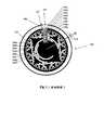
典型的に、従来技術の一回転アブソリュート・ロータリー・エンコーダでは、様々な光学特性をもつセクションにより構成された円形トラックのパターンが回転軸に固定されたディスクに付けられる。このような光学特性は、セクションの透明性(光透過性または光不透過性)でもよい。従来技術のディスクの例が図1に示され、ディスク上の各円形トラックは光学センサが設けられ、各センサが所与の時点でセンサと向かい合うパターンのセクションの光学特性を表現する信号を出力するように光線によって走査される。 Typically, in a prior art single-turn absolute rotary encoder, a pattern of circular tracks composed of sections with various optical properties is applied to a disk fixed to a rotating shaft. Such optical properties may be the transparency of the section (light transmissive or light opaque). An example of a prior art disk is shown in FIG. 1, where each circular track on the disk is provided with an optical sensor, and each sensor outputs a signal representing the optical properties of the section of the pattern facing the sensor at a given time. So that it is scanned by the rays.
センサによって出力される信号は、バイナリの「0」または「1」信号(ビット)である。これらのビット信号は、ディスクの回転角度に依存するバイナリコードを作成するために合成され、コードはその後に所定のテーブルに従って位置情報に変換される。 The signal output by the sensor is a binary “0” or “1” signal (bit). These bit signals are combined to create a binary code that depends on the rotation angle of the disk, and the code is then converted into position information according to a predetermined table.
典型的に、特殊なタイプのコード(グレイコード)を生じる特殊なパターンが使用される。当該技術において知られているように、グレイコードという用語は、コードの1ビットだけがエンコーダディスクの2個の連続的なインクリメントの間に変更されるコードを指す。このタイプのコードはインクリメント間の移行時に誤ったコードの生成を防止する。 Typically, a special pattern is used that produces a special type of code (Gray code). As known in the art, the term Gray code refers to a code in which only one bit of the code is changed between two successive increments of the encoder disk. This type of code prevents the generation of incorrect code when transitioning between increments.
上述のタイプの従来技術のエンコーダの不利点は、複数の同心トラックが可動部材の位置に関する情報を提供するために必要とされることである。各トラックは適度な精度のために最低限の面積を必要とするので、ディスクの全体のサイズが大きく望ましくない。たとえば、図1に示されたディスクパターンは8本の同心トラックを有し、最小直径をもつトラックは、寸法公差が非常に小さくなるように、最大直径をもつトラックと同じ角精度を持たなければならない。その結果、従来技術のエンコーダでは、最小可能エンコーダのディスクサイズは制限され、それによって製造コストが増加する。 A disadvantage of prior art encoders of the type described above is that multiple concentric tracks are required to provide information regarding the position of the movable member. Since each track requires a minimum area for reasonable accuracy, the overall size of the disk is large and undesirable. For example, the disk pattern shown in FIG. 1 has 8 concentric tracks, and the track with the smallest diameter must have the same angular accuracy as the track with the largest diameter so that the dimensional tolerances are very small. Don't be. As a result, in prior art encoders, the disk size of the smallest possible encoder is limited, thereby increasing manufacturing costs.
トラックの最低限の本数を削減するためにいくつかの試みが行われた。欧州特許出願公開第0332244A1号は、コーディングトラックと、いわゆる「クロック」トラックとの2本のトラックだけが使用される仕組みを示している。しかし、この特許は依然として2本のトラックを必要とし、作成されるコードはグレイコードではなく、すなわち、2個の隣接したインクリメントに対し、「クロック」トラックの2ビット以上が変更される位置がある。 Several attempts have been made to reduce the minimum number of tracks. EP-A-0332244A1 shows a mechanism in which only two tracks are used, a coding track and a so-called “clock” track. However, this patent still requires two tracks and the code created is not a Gray code, ie there are positions where two or more bits of the “clock” track are changed for two adjacent increments. .
NagaseとHigashiによる国際公開第91/00984号公報は、1トラックのアブソリュート・コード・システムについて説明している。しかし、この特許は、台数「n」台のセンサが「n」個の連続したインクリメントに設置されることを必要とする。センサが互いに隣接して配置することができるように、センサはそのために非常に小型でなければならない。このことは、特別に設計された光電子チップの製造を必要とする。このようなチップは特定のエンコーダサイズ毎に設計されるべきであり、したがって、異なるサイズの数種類のエンコーダに使用できない。 International Publication No. 91/00984 by Nagase and Higashi describes a one-track absolute code system. However, this patent requires that “n” sensors be installed in “n” consecutive increments. The sensors must therefore be very small so that the sensors can be placed adjacent to each other. This requires the production of specially designed optoelectronic chips. Such a chip should be designed for each specific encoder size and therefore cannot be used for several types of encoders of different sizes.
別の公知の手法は、6個のインクリメントに対し6個のコードを供給する3台のセンサを含んでいる単一トラックを利用する。この手法はロータ極に関する位置情報を取り出すためにブラシレスサーボモータと共に広く用いられ、この場合、ホールセンサがロータの磁極を感知するために一般に使用される。しかし、この手法は3台のセンサの場合に限り適用可能であり、位置情報分解能は6個の値しか持たない。 Another known approach utilizes a single track that includes three sensors that provide six codes for six increments. This approach is widely used with brushless servomotors to retrieve position information about rotor poles, where Hall sensors are commonly used to sense the rotor poles. However, this method is applicable only to the case of three sensors, and the position information resolution has only six values.
本発明の目的は、上記の1つ以上の観点において利点があるエンコーダを提供することである。特に、本発明の目的は、第1の部材の位置を第2の部材に関して正確に示すために、単一トラックだけを必要とし、互いに間隔をあけられた関係にある4台以上のセンサを収容する能力があるエンコーダを提供することである。本発明のさらなる目的は、グレイコードに基づくバイナリ出力を生成し、可動部材の各インクリメンタル移動がセンサによって出力されたバイナリコード中のビットのうちの1個だけのバイナリ値を変化させるエンコーダを提供することである。 It is an object of the present invention to provide an encoder that has advantages in one or more of the above aspects. In particular, it is an object of the present invention to accommodate four or more sensors in a spaced-apart relationship, requiring only a single track to accurately indicate the position of the first member with respect to the second member. It is to provide an encoder capable of A further object of the present invention is to provide an encoder that generates a binary output based on a Gray code, and that each incremental movement of the movable member changes the binary value of only one of the bits in the binary code output by the sensor. That is.
本発明の一態様によれば、第1の部材の位置を第2の部材に関して正確に示すエンコーダであって、第1の部材のトラックの連続的なインクリメンタルロケーションに置かれ、各素子がバイナリ値である「0」および「1」のうちの一方を表現する、第1の部材のトラックに支持された機械感知可能な素子のパターンと、各センサが位置合わせされた機械感知可能な素子のバイナリ値に対応する出力を生成するために位置合わせされた各機械感知可能な素子のバイナリ値を感知し、それによって、すべてのセンサの出力が第2の部材に関する第1の部材の位置を識別する「n」ビットのバイナリコードを構成するように、第1の部材のトラックに近接し、かつ、第1の部材の機械感知可能な素子と位置合わせ可能である、第2の部材の複数の離間したロケーションで第2の部材によって支持された複数「n」台(但し、「n」は「3」より大きい)のセンサと、を備えるエンコーダが提供される。 According to one aspect of the present invention, an encoder that accurately indicates the position of a first member with respect to a second member, wherein the elements are placed in successive incremental locations on a track of the first member, each element being a binary value. A pattern of machine-sensitive elements supported on the track of the first member representing one of “0” and “1”, and a binary of machine-sensitive elements in which each sensor is aligned Sensing the binary value of each machine-sensitive element aligned to produce an output corresponding to the value, whereby the outputs of all sensors identify the position of the first member relative to the second member A plurality of second members that are proximate to the tracks of the first member and are alignable with the machine-sensitive elements of the first member to constitute an “n” bit binary code. During the location of a plurality "n" base supported by the second member (where "n" is "3" greater than) encoder and a sensor is provided.
好ましくは、第1の部材のトラックに支持された機械感知可能な素子のパターン、および第1の部材のトラックに関する第2の部材によって支持されたセンサの間隔は、グレイコードを作成し、すなわち、これらは、第1の部材の各インクリメンタル移動がセンサによって出力されたバイナリ数のビットのうちの1ビットだけのバイナリ値を変化させるといったものである。 Preferably, the pattern of machine-sensitive elements supported on the track of the first member and the spacing of the sensors supported by the second member with respect to the track of the first member creates a Gray code, i.e. These are such that each incremental movement of the first member changes the binary value of only one of the binary bits output by the sensor.
記載された好ましい実施形態におけるさらなる特徴によれば、「n」は「4」と「10」との間であり、トラック上の機械感知可能な素子の連続的なインクリメンタルロケーションは「2n」個未満である。記載された好ましい一実施形態では、7台のセンサと、センサによって出力された7ビットバイナリコードによって示され得る可動部材の98個のインクリメンタル位置とが存在する。According to still further features in the described preferred embodiments “n” is between “4” and “10”, and there are “2n ” continuous incremental locations of machine-sensitive elements on the track. Is less than. In one preferred embodiment described, there are 7 sensors and 98 incremental positions of the movable member that can be indicated by the 7-bit binary code output by the sensors.
上述されているように、本発明は、光学式エンコーダに関して特に有用である。したがって、本発明の別の態様によれば、第1の部材の位置を第2の部材に関して正確に示す光学式エンコーダであって、第1の部材のトラック上の連続的なインクリメンタルロケーションに置かれ、各々がバイナリ値である「0」および「1」のうちの一方を表現する、第1の部材の単一のトラックに支持された光学素子のパターンと、各光学センサが位置合わせされた光学素子のバイナリ値に対応する出力を生成するために位置合わせされた各光学素子のバイナリ値を感知し、それによって、すべての光学センサの出力が第2の部材に関する第1の部材の位置を識別する「n」ビットのバイナリコードを構成するように、第1の部材のトラックに近接し、かつ、第1の部材の光学素子と位置合わせ可能である、第2の部材の複数の離間したロケーションで第2の部材によって支持された複数「n」台(但し、「n」は「3」より大きい)の光学センサとを備え、第1の部材の単一のトラックに支持された光学素子のパターン、および、第1の部材の単一のトラックに関して第2の部材によって支持された光学センサの間隔が、第1の部材の各インクリメンタル移動が光学センサによって出力されたバイナリコードのビットのうちの1ビットだけのバイナリ値を変化させるようなパターンおよび間隔である、光学式エンコーダが提供される。 As mentioned above, the present invention is particularly useful with optical encoders. Thus, according to another aspect of the present invention, an optical encoder that accurately indicates the position of a first member with respect to a second member, placed in a continuous incremental location on a track of the first member. , A pattern of optical elements supported on a single track of the first member, each representing one of binary values “0” and “1”, and the optics in which each optical sensor is aligned Sensing the binary value of each optical element aligned to produce an output corresponding to the binary value of the element, whereby the output of all optical sensors identifies the position of the first member relative to the second member A plurality of spaced apart second members that are proximate to the tracks of the first member and alignable with the optical elements of the first member so as to form an "n" bit binary code And an optical element supported by a single track of the first member, wherein the optical member comprises a plurality of “n” level optical sensors supported by the second member at the location, where “n” is greater than “3” And the spacing of the optical sensors supported by the second member with respect to a single track of the first member is the bit of binary code in which each incremental movement of the first member is output by the optical sensor. An optical encoder is provided that has a pattern and spacing that changes the binary value of only one bit.
本発明のさらなる態様によれば、第1の部材の位置を第2の部材に関して正確に示す方法であって、第1の部材のトラックの連続的なインクリメンタルロケーションに置かれ、各々がバイナリ値である「0」および「1」のうちの一方を表現する、第1の部材のトラックに支持された機械感知可能な素子のパターンを設けるステップと、各センサが位置合わせされた機械感知可能な素子のバイナリ値に対応する出力を生成するため位置合わせされた各機械感知可能な素子のバイナリ値を感知し、それによって、すべてのセンサの出力が第2の部材に関する第1の部材の位置を識別する「n」ビットのバイナリコードを構成するように、第1の部材のトラックに近接し、かつ、第1の部材の機械感知可能な素子と位置合わせ可能である、第2の部材の複数の離間したロケーションで第2の部材によって支持された複数「n」台(但し、「n」は「3」より大きい)のセンサを設けるステップと、各センサが位置合わせされた機械感知可能な素子に基づいて各センサから1ビット信号を出力するステップと、すべてのセンサからのビットをバイナリ数に結合するステップと、バイナリ数を第2の部材に関する第1の部材の位置を示す情報に加工するステップと、を備える方法が提供される。 According to a further aspect of the present invention, there is provided a method for accurately indicating the position of a first member with respect to a second member, wherein the first member is placed at successive incremental locations on a track of the first member, each being a binary value. Providing a pattern of machine-sensitive elements supported on the track of the first member representing one of certain “0” and “1”, and a machine-sensitive element in which each sensor is aligned Sensing the binary value of each machine-sensitive element aligned to produce an output corresponding to the binary value of the sensor, whereby all sensor outputs identify the position of the first member relative to the second member A second member that is proximate to a track of the first member and is alignable with a machine-sensitive element of the first member so as to constitute a binary code of “n” bits to Providing a plurality of "n" stage sensors (where "n" is greater than "3") supported by a second member at a plurality of spaced locations of the material, and a machine sensing where each sensor is aligned Outputting a 1-bit signal from each sensor based on possible elements, combining the bits from all sensors into a binary number, and information indicating the position of the first member relative to the second number of the binary number. Is provided.
本発明のさらなる特徴および利点は、以下の説明から明らかであるだろう。 Additional features and advantages of the present invention will be apparent from the description below.
本発明は、本明細書において、単に例として、添付の図面を参照して説明される。
前述の図面および以下の記載は、主に本発明の概念的側面および好ましい実施形態と現在考えられているものを含むその可能な実施形態の理解を容易にする目的のために与えられることが理解されなければならない。明解さおよび簡潔さのため、当業者が通常の技術および設計を使用して記載された発明を理解し実践できるために必要である以上の多くの詳細を与える試みはなされていない。さらに、記載された実施形態が例示だけを目的とすること、そして本発明がここに記載された以外の他の形態および用途で具体化されうることは理解されなければならない。 It is understood that the foregoing drawings and the following description are provided primarily for the purpose of facilitating the understanding of possible embodiments, including those presently considered conceptual aspects and preferred embodiments of the invention. It must be. For the sake of clarity and brevity, no attempt has been made to provide more details than are necessary for one skilled in the art to understand and practice the described invention using conventional techniques and designs. Further, it is to be understood that the described embodiments are for illustrative purposes only, and that the invention may be embodied in other forms and applications than those described herein.
図1の従来技術のロータリーエンコーダ
図1に示された従来技術のエンコーダは、固定部材102に関して回転できるように回転軸(図示せず)に固定されるべきであり、固定部材102に関して回転軸の位置を正確に示すために光学センサ106によって感知されるべきである光学素子104の形をした機械感知可能な素子のパターンを支持するディスク100を含む光学式ロータリーエンコーダである。光学素子104は複数の同心トラックに位置している。光学素子は、光透過(たとえば、透明)素子を表す白色区域、および、光不透過(たとえば、吸収または反射)素子を表す黒色区域として図示されている。図1に示されるように、光学素子104は8個の同心円形アレイ104a〜104hに配置されている。Prior Art Rotary Encoder of FIG. 1 The prior art encoder shown in FIG. 1 should be fixed to a rotating shaft (not shown) so that it can rotate with respect to the fixed
全体的に106で表された光学センサのグループは、機械的接続部108によって概略的に示されているように固定部材102によって固定的に支持される。光学素子104の同心円104a〜104hのそれぞれと位置合わせされるように放射状直線に配置された8台のセンサ106a〜106hが存在する。各センサ106a〜106hは、このようにして、各光学素子の光学特性に応じたバイナリ信号を出力するためにどの時点においても各センサと位置合わせされた光学素子104a〜104hの光学特性を検出するように位置決めされる。たとえば、光透過素子は「1」によって表現され、光不透過素子は「0」によって表現されることがある。 The group of optical sensors, generally designated 106, is fixedly supported by the fixing
どの時点においても8台のセンサ106a〜106hによって出力された8個のバイナリ信号の組み合わせは、このようにして、光学ディスク100の各インクリメンタル位置に一意であるバイナリコードを生じる。図1に示された実施例では、光学素子104の8個の同心円が光学ディスク100の256個のインクリメンタル位置を画定し、各インクリメンタル位置は、2個の隣接した光学素子の同じ基準点を通って延在する2本の放射状直線間のセクタ角109によって画定される。 The combination of the eight binary signals output by the eight
図1のパターンの特有の特性は、コードが「グレイコード」であること、すなわち、2個の隣接セクタのコードが1ビットしか異ならないことである。このことは、パターンにある程度の不正確さが存在するとしても、隣接セクタ間での移行時にコードの読み出しを明確にすることを可能にする。エンコーダのためのこのグレイコードの使用は公知の手法である。 A unique characteristic of the pattern of FIG. 1 is that the code is a “Gray code”, that is, the codes of two adjacent sectors differ by only one bit. This makes it possible to clarify the reading of the code when transitioning between adjacent sectors, even if there is some degree of inaccuracy in the pattern. The use of this Gray code for the encoder is a known technique.
図1のパターンを使用するエンコーダの主要な不利点は、パターンが数本の同心トラックに分布していることである。各トラックは、所要の精度を実現するために最低限の幅および最低限の半径を有する。したがって、所望の精度を実現するため、ディスクは、最低限の半径と、トラック数で乗じた最低限の幅との合計より大きい半径を有し、比較的大型サイズのエンコーダになる。 A major disadvantage of encoders using the pattern of FIG. 1 is that the pattern is distributed over several concentric tracks. Each track has a minimum width and a minimum radius to achieve the required accuracy. Thus, to achieve the desired accuracy, the disk has a radius that is greater than the sum of the minimum radius and the minimum width multiplied by the number of tracks, resulting in a relatively large size encoder.
本発明
概要
後述されるような新規エンコーダは、位置を正確に位置決めされるべき可動部材が、単一トラックの周りに間隔をあけられた複数の光学センサ、または、その他のタイプのセンサと協働可能である単一トラックの光学素子、または、その他の機械感知可能な要素をだけを含むようにすることを可能にする。新規構成は、このようにして、エンコーダのサイズの大幅な小型化と、エンコーダのサイズの小型化およびパターンの簡素化による生産コストの低減といったいくつかの重要な利点をもたらす。センサが互いに間隔をあけられ、したがって、標準的なサイズでも構わないため、エンコーダは標準的な光電子装置のセンサを利用できるので、生産コストはさらに実質的に低減される。さらなる重要な利点は、新規エンコーダが可動部材が多数の移動のインクリメントに分割されることを可能にするので、新規エンコーダが可動部材の位置の決定の際に遙かに高い精度を可能にすることである。The present invention
Overview New encoders, as described below, allow a movable member to be accurately positioned to cooperate with multiple optical sensors or other types of sensors spaced around a single track. It is possible to include only a single track of optical elements or other machine-sensitive elements. The new configuration thus provides several important advantages, such as a significant reduction in the size of the encoder and a reduction in production costs due to a reduction in the size of the encoder and simplification of the pattern. Since the sensors are spaced apart from each other and thus may be of standard size, the production cost is further substantially reduced since the encoder can utilize standard optoelectronic device sensors. A further important advantage is that the new encoder allows a much higher accuracy in determining the position of the movable member, since the new encoder allows the movable member to be divided into a number of movement increments. It is.
発明の2つの好ましい実施形態が実施例の目的のため後述される。図2に示された第1の実施形態はロータリーエンコーダの形式であり、図3に示された第2の実施形態はリニアエンコーダの形式である。両方の場合において、機械感知可能な素子は光学素子であり、センサは光学センサであるが、発明は、ブラシおよびスリップリングを使用するエンコーダと、電磁素子を使用するエンコーダなどのようなその他のタイプのエンコーダで実施可能であることが理解されるであろう。 Two preferred embodiments of the invention are described below for purposes of example. The first embodiment shown in FIG. 2 is in the form of a rotary encoder, and the second embodiment shown in FIG. 3 is in the form of a linear encoder. In both cases, the machine sensitive element is an optical element and the sensor is an optical sensor, but the invention is not limited to other types such as encoders using brushes and slip rings, encoders using electromagnetic elements, etc. It will be understood that this can be implemented with the following encoders.
図2の光学式エンコーダ
図2は、機械感知可能(光学)素子のパターンが、多数(この場合では98個)のインクリメンタル位置またはセクタに分割された単一トラック回転式部材またはディスク200で支持され、固定部材202によって支持された7台のセンサのグループと協働可能であり、光学素子の円形トラックの周りで間隔をあけられている、光学式ロータリーエンコーダを示している。FIG. 2 shows that a pattern of machine-sensitive (optical) elements is supported by a single track rotary member or
したがって、図2において分かるように、204で表された光学素子は、光学ディスク200の周囲の周りの単一円形トラックに配置された複数の光透過素子204aおよび複数の光不透過素子204bで構成される。全体的に206で表された光学センサは、光学要素204に近接して、206a〜206gに示されるように、円形アレイに配置された7台のセンサによって構成され、光学ディスク200のインクリメンタル位置またはセクタ毎に、各センサ206a〜206gが1個ずつの光学素子によって表現されるバイナリ値を感知するため光学素子204のうちの1個と位置合わせされる。 Thus, as can be seen in FIG. 2, the optical element represented by 204 is composed of a plurality of light
したがって、光学ディスク200のインクリメンタル位置またはセクタ毎に、7台のセンサ206a〜206gが、各センサが位置合わせされている光学素子の光学特性を表現するバイナリビット(0または1)を出力することが分かるであろう。したがって、光学ディスクのインクリメンタル位置(セクタ)毎に、7ビットのバイナリコードがその位置を示すためにセンサによって出力されるであろう。 Therefore, for each incremental position or sector of the
図2においてさらに分かるように、7台のセンサ206a〜206gは互いに等間隔にされ、それによって、標準的な光学センサが使用されることを可能にする。図2に示された実施例では、光学ディスク200は、各インクリメンタル位置が光学素子204(光透過素子204aまたは光不透過素子204bのいずれか)によって占有された98個のインクリメンタル位置(セクタ)208に分割され、7台のセンサ206a〜206gのうちの1台ずつが14個のインクリメンタル位置(セクタ)の距離で互いに間隔をあけられる。 As can be further seen in FIG. 2, the seven
図2に示されたエンコーダ構成は、より小型の構成、回転式ディスクの位置のより正確な決定、および、より大型の市販センサの許された使用という利点だけでなく、グレイコードの形式のバイナリ出力を生成するというさらなる利点を提供する。上述されているように、グレイコードでは、2個の隣接したインクリメンタル位置(セクタ)は、回転式ディスクの各インクリメンタル移動がセンサによって出力された7ビットのバイナリコードのうちの1ビットだけの出力バイナリ値を変化させるように、1ビットだけが相違する。さらに上述されているように、グレイコードは、パターンにある程度の不正確さが存在するとしても、隣接したインクリメンタル位置間の移行時にコードの読み出しが明確にされることを可能にする。 The encoder configuration shown in FIG. 2 not only benefits from a smaller configuration, more accurate determination of the position of the rotating disk, and the permitted use of larger commercial sensors, but also a binary in the form of a Gray code. Provides the additional advantage of generating output. As described above, in Gray code, two adjacent incremental positions (sectors) are the output binary of only one bit of the 7-bit binary code output by the sensor for each incremental movement of the rotating disk. Only one bit is different to change the value. Further, as described above, the Gray code allows code reading to be clarified when transitioning between adjacent incremental positions, even though some inaccuracy exists in the pattern.
図2に示された実施例は98個のインクリメンタル位置および7台のセンサを示しているが、発明はより多数または少数のインクリメンタル位置と共に、および、より多数または少数のセンサと共に実施できることが理解されるであろう。インクリメンタル位置の個数(p)は、センサの台数(n)で乗された「2」より常に小さくすべきであり、すなわち、
p<2n
である。Although the embodiment shown in FIG. 2 shows 98 incremental positions and 7 sensors, it is understood that the invention can be implemented with more or fewer incremental positions and with more or fewer sensors. It will be. The number of incremental positions (p) should always be smaller than “2” multiplied by the number of sensors (n), ie
p <2n
It is.
図1に示されているように、7本のトラックを使用するグレイコードに基づくパターンはより多数のセクタ(インクリメンタル位置)を提供することが可能であり、
p=2n
である。しかし、このより多数個(p)のセクタを提供するため、より大きい直径のパターンが既に指摘した通り必要とされるので、数本のトラックが使用されるべきである。これに対して、本発明のパターンによって提供されるより少数個(p)のセクタは、1本のトラックしか必要とされないので、標準的なセンサの使用と、センサの機械的取り付けの精度要求の引き下げとを可能にするということによってかなり補われる。As shown in FIG. 1, a Gray code based pattern using 7 tracks can provide a larger number of sectors (incremental positions)
p = 2n
It is. However, to provide this larger number (p) of sectors, several tracks should be used because larger diameter patterns are required as already pointed out. In contrast, the smaller number of sectors (p) provided by the pattern of the present invention requires only one track, so the use of standard sensors and the accuracy requirements for mechanical mounting of the sensors This is largely compensated by allowing for a reduction.
本発明によるパターンを見つけるため、コンピュータプログラムが所要の条件、すなわち、
1)結果として得られるコードがグレイコードであること、および、
2)各セクタ(インクリメンタル位置)に対し1個のコードだけが存在すること
を実証するパターンを探索するために使用可能である。In order to find the pattern according to the invention, the computer program has the required conditions, i.e.
1) the resulting code is a Gray code, and
2) It can be used to search for patterns that demonstrate that there is only one code for each sector (incremental position).
このようなコンピュータプログラムの原理が図4のブロック図に示されるステップ、すなわち、
(a)セクタの個数pおよびセンサの台数nを読み出すステップと、
(b)一様に分布したセクタを、エンコーダディスクの初期位置に対する特性がセンサによって感知されるセクタを表現する「感知されたセクタ」として設定するステップと、
(c)セクタの物理特性を表現する1個のブール値を各セクタにランダムに帰属させるランダムパターンを作成するステップと、
(d)感知されたセクタのブール値に従って第1のコードを計算するステップと、
(e)感知されたセクタを所定の方向に次のセクタへ変更するステップと、
(f)第2のコードを計算するステップと、
(g)コードのビット同士を比較するステップと、
(h)コードが2ビット以上相違するならば、1ビットを除いてすべての異なるビットに対し、感知されたセクタに帰属させられたブール値を変更するステップと、
(i)2個以上の異なるビットが少なくともp個の連続した時点に対する第1のコードと第2のコードとの間で見つけられなくなるまで、ステップ(d)〜(h)を繰り返すステップと、
(j)0から2^nまでのすべてのコードに値0を帰属させるステップと、
(k)感知されたセクタに従って第1のコードを計算するステップと、
(l)当該コードに帰属させられた値を1ずつインクリメントするステップと、
(m)当該コードに帰属させられた値が1より大きいならば、新しいパターンを試行するためにステップ(c)へ進むステップと、
(n)ステップ(i)からステップ(m)をp回繰り返す(ステップ(m)が存在しないならばループする)ステップと、
(o)見つけられたパターンを出力するステップと、
によって明らかにされ例示される。The principle of such a computer program is the steps shown in the block diagram of FIG.
(A) reading the number of sectors p and the number of sensors n;
(B) setting the uniformly distributed sector as a “sensed sector” representing a sector whose characteristics relative to the initial position of the encoder disk are sensed by the sensor;
(C) creating a random pattern for randomly assigning one Boolean value representing the physical characteristics of the sector to each sector;
(D) calculating a first code according to a sensed sector Boolean value;
(E) changing the detected sector to the next sector in a predetermined direction;
(F) calculating a second code;
(G) comparing the bits of the code;
(H) changing the Boolean value attributed to the sensed sector for all the different bits except one if the codes differ by 2 bits or more;
(I) repeating steps (d)-(h) until two or more different bits are not found between the first code and the second code for at least p consecutive points;
(J) assigning the value 0 to all codes from 0 to 2 ^ n;
(K) calculating a first code according to the sensed sector;
(L) incrementing the value attributed to the code by one;
(M) if the value attributed to the code is greater than 1, proceed to step (c) to try a new pattern;
(N) repeating steps (i) to (m) p times (looping if step (m) does not exist);
(O) outputting the found pattern;
Revealed and exemplified by
ステップ(a)および(b)は初期化ステップであり、ステップ(c)〜(h)はグレイコードを作成し、ステップ(j)〜(m)はセクタ(インクリメンタル位置)毎に1個の一意のコードに対するコードを設定し、残りのステップ(n)および(o)は見つけられたパターンの出力を生成する。 Steps (a) and (b) are initialization steps, steps (c)-(h) create a gray code, and steps (j)-(m) are one unique for each sector (incremental position). The remaining steps (n) and (o) generate an output of the found pattern.
その他のプログラムおよび最適化が1つずつの特定の用途に従う新規エンコーダに適したパターンを見つけるため使用可能であることが理解されるであろう。 It will be appreciated that other programs and optimizations can be used to find a suitable pattern for a new encoder according to each particular application.
図3のリニアエンコーダ
図3は、この場合では同様に光学素子である複数の機械感知可能な素子が可動部材300の単一リニアトラックに支持され、センサ、すなわち、光学センサが固定部材302のリニアアレイに固定される、リニアエンコーダで実施される発明を示している。The linear encoder of FIG. 3 shows that a plurality of machine-sensitive elements, which in this case are also optical elements, are supported on a single linear track of the
このようにして、図3に示されているように、可動部材300の機械感知可能な素子304も同様に光透過素子および光不透過素子の光学素子であるが、直線状に配置されている。光学素子は、306a、306bおよび306cでそれぞれ表され、各区間が20個のインクリメンタル位置(セクタ)38で構成されている3個の類似した区間に分割される。 In this way, as shown in FIG. 3, the mechanically
固定部材302は、同様に単一ラインに配置され、互いに等間隔をあけられた5台のセンサ308a〜308eを支持する。固定部材302に関して可動部材300の初期位置において、5台のセンサ308a〜308eのアレイは、光学素子の1区間、すなわち、図3に示されているように中央区間306bの範囲内に位置している。 The fixing
したがって、図3に示されたパターンは直線状であり、かつ、周期的であることが分かるであろう。区間306a〜306cの1つずつは、図2に示されたロータリーエンコーダの「展開」パターンであるとみなすことができる。 Thus, it will be appreciated that the pattern shown in FIG. 3 is linear and periodic. Each of the
一様に分布したセンサの好ましい実施形態では、1区間未満の位置が考慮される。その場合、n台のセンサに対する「一様に分布した」という用語は、センサiによって感知された位置x(i)が、1からnまでのすべてのiに対し、
[(x(i+1)−x(i)) モジュロ L]=±L/n
の関係を検証することを意味し、式中、Lはパターンの1区間の長さである。In a preferred embodiment of a uniformly distributed sensor, positions less than one section are considered. In that case, the term “uniformly distributed” for n sensors means that the position x (i) sensed by sensor i is for all i from 1 to n.
[(X (i + 1) −x (i)) modulo L] = ± L / n
In the formula, L is the length of one section of the pattern.
本発明は、2つの好ましい実施形態に関して説明されているが、これらの実施形態は実施例の目的のためだけに記載され、多様な変形がなされてもよいことが理解されるであろう。たとえば、一方の部材を可動にさせ、もう一方の部材を固定するのではなく、2つの部材が互いに関して移動できるようにすることが可能である。さらに、インクリメンタル位置の個数は、センサの台数が適切に増減されるのに合わせて、特定の用途のために要求どおりに増減できる。また、その他の機械感知可能な素子およびセンサが上述されているように使用されてもよい。その上、図3のリニアエンコード方式の実施形態では、より少数または多数の区間が使用でき、センサの台数は違ってもよく、センサの位置決めも異なってもよい。 Although the invention has been described with reference to two preferred embodiments, it will be understood that these embodiments are described solely for purposes of example and that various modifications may be made. For example, one member can be movable and the other member can be fixed, rather than allowing the two members to move relative to each other. Furthermore, the number of incremental positions can be increased or decreased as required for a particular application as the number of sensors is appropriately increased or decreased. Other machine-sensitive elements and sensors may also be used as described above. In addition, in the linear encoding scheme embodiment of FIG. 3, fewer or more sections can be used, the number of sensors can be different, and the positioning of the sensors can be different.
本発明の多くの他の変形、変形および適用は明らかであるだろう。 Many other variations, modifications and applications of the invention will be apparent.
Claims (20)
Translated fromJapanese前記第1の部材のトラックの連続的なインクリメンタルロケーションに置かれ、各素子がバイナリ値である「0」および「1」のうちの一方を表現する、前記第1の部材のトラックに支持された機械感知可能な素子のパターンと、
各センサが位置合わせされた機械感知可能な素子のバイナリ値に対応する出力を生成するために位置合わせされた各機械感知可能な素子のバイナリ値を感知し、それによって、すべてのセンサの出力が前記第2の部材に関する前記第1の部材の位置を識別する「n」ビットのバイナリコードを構成するように、前記第1の部材の前記トラックに近接し、かつ、前記第1の部材の前記機械感知可能な素子と位置合わせ可能である、前記第2の部材の複数の離間したロケーションで前記第2の部材によって支持された複数「n」台(但し、「n」は「3」より大きい)のセンサと、
を備えるエンコーダ。An encoder that accurately indicates the position of the first member with respect to the second member;
Placed in a continuous incremental location of the first member track and supported by the first member track, each element representing one of the binary values "0" and "1" A pattern of machine-sensitive elements;
Each sensor senses the binary value of each registered machine sensitive element to produce an output corresponding to the binary value of the aligned machine sensitive element, so that the output of all sensors is Proximity to the track of the first member and so as to constitute an “n” bit binary code identifying the position of the first member relative to the second member, and the first member of the first member A plurality of “n” platforms supported by the second member at a plurality of spaced locations of the second member that are alignable with a machine sensitive element, where “n” is greater than “3” Sensor)
An encoder comprising:
前記トラックは前記回転式部材上の単一の円形トラックであり、
前記複数「n」台のセンサは前記第2の部材に支持された円形アレイの形態である、
請求項1に記載のエンコーダ。The first member is a rotary member;
The track is a single circular track on the rotating member;
The plurality of “n” sensors are in the form of a circular array supported by the second member.
The encoder according to claim 1.
前記トラックは単一の直線状トラックであり、
前記複数「n」台のセンサは前記第2の部材に支持された直線状アレイの形態である、
請求項1に記載のエンコーダ。The first member is a linearly movable member;
The track is a single linear track;
The plurality of “n” sensors are in the form of a linear array supported by the second member.
The encoder according to claim 1.
前記第1の部材の単一のトラック上の連続的なインクリメンタルロケーションに置かれ、各々がバイナリ値である「0」および「1」のうちの一方を表現する、前記第1の部材の単一のトラックに支持された光学素子のパターンと、
各光学センサが位置合わせされた光学素子のバイナリ値に対応する出力を生成するために位置合わせされた各光学素子のバイナリ値を感知し、それによって、すべての光学センサの出力が前記第2の部材に関する前記第1の部材の位置を識別する「n」ビットのバイナリコードを構成するように、前記第1の部材の前記トラックに近接し、かつ、前記第1の部材の前記光学素子と位置合わせ可能である、前記第2の部材の複数の離間したロケーションで前記第2の部材によって支持された複数「n」台(但し、「n」は「3」より大きい)の光学センサと
を備え、前記第1の部材の単一のトラックに支持された前記光学素子のパターン、および、前記第1の部材の単一のトラックに関して前記第2の部材によって支持された前記光学センサの間隔が、前記第1の部材の各インクリメンタル移動が前記光学センサによって出力されたバイナリコードの前記ビットのうちの1ビットだけのバイナリ値を変化させるようなものである、光学式エンコーダ。An optical encoder that accurately indicates the position of the first member with respect to the second member,
A single single member of the first member, placed in successive incremental locations on a single track of the first member, each representing one of the binary values "0" and "1" A pattern of optical elements supported by a track of
Each optical sensor senses the binary value of each aligned optical element to produce an output corresponding to the binary value of the aligned optical element, so that the output of all optical sensors is Proximity to the track of the first member and position with the optical element of the first member so as to constitute an "n" bit binary code identifying the position of the first member relative to the member And a plurality of “n” platforms (where “n” is greater than “3”) supported by the second member at a plurality of spaced locations of the second member, A pattern of the optical element supported on a single track of the first member and of the optical sensor supported by the second member with respect to a single track of the first member. Septum is what each incremental movement of said first member, such as to change the binary value of only one bit of said bit binary code outputted by said optical sensor, the optical encoder.
前記単一のトラックは前記回転式部材上の円形トラックであり、
前記複数「n」台の光学センサは前記第2の部材に支持された円形アレイの形態である、
請求項10に記載の光学式エンコーダ。The first member is a rotary member;
The single track is a circular track on the rotating member;
The plurality of “n” optical sensors are in the form of a circular array supported by the second member.
The optical encoder according to claim 10.
前記単一のトラックは直線状トラックであり、
前記複数「n」台の光学センサは前記第2の部材に支持された直線状アレイの形態である、
請求項10に記載の光学式エンコーダ。The first member is a linearly movable member;
The single track is a straight track;
The plurality of “n” optical sensors are in the form of a linear array supported by the second member.
The optical encoder according to claim 10.
前記第1の部材のトラックの「p」個の連続的なインクリメンタルロケーションに置かれ、各々がバイナリ値である「0」および「1」のうちの一方を表現する、前記第1の部材のトラックに支持された機械感知可能な素子のパターンを設けるステップと、
各センサが位置合わせされた機械感知可能な素子のバイナリ値に対応する出力を生成するため位置合わせされた各機械感知可能な素子のバイナリ値を感知し、それによって、すべてのセンサの出力が前記第2の部材に関する前記第1の部材の位置を識別する「n」ビットのバイナリコードを構成するように、前記第1の部材の前記トラックに近接し、かつ、前記第1の部材の前記機械感知可能な素子と位置合わせ可能である、前記第2の部材の複数の離間したロケーションで前記第2の部材によって支持された複数「n」台(但し、「n」は「3」より大きい)のセンサを設けるステップと、
各センサが位置合わせされた機械感知可能な素子に基づいて各センサから1ビット信号を出力するステップと、
すべてのセンサからのビットをバイナリ数に結合するステップと、
前記バイナリ数を第2の部材に関する第1の部材の位置を示す情報に加工するステップと
を含む方法。A method of accurately indicating the position of a first member with respect to a second member,
The first member track, placed in “p” consecutive incremental locations of the first member track, each representing one of binary values “0” and “1”. Providing a pattern of machine-sensitive elements supported on the substrate;
Each sensor senses the binary value of each aligned machine-sensitive element to produce an output corresponding to the binary value of the aligned machine-sensitive element, so that the output of all sensors is Proximity to the track of the first member and the machine of the first member to constitute an “n” bit binary code identifying the position of the first member with respect to a second member A plurality of “n” platforms supported by the second member at a plurality of spaced locations of the second member that are alignable with a sensitive element, where “n” is greater than “3” Providing a sensor of:
Outputting a 1-bit signal from each sensor based on the machine-sensitive element with which each sensor is aligned;
Combining bits from all sensors into a binary number;
Processing the binary number into information indicative of the position of the first member relative to the second member.
(a)インクリメンタルロケーションの個数pおよびセンサの台数nを読み出すステップと、
(b)第1の部材の初期位置に対してセンサによって感知される機械感知可能な素子に対する一様に分布したインクリメンタルロケーションを設定するステップと、
(c)各々のインクリメンタルロケーションの物理特性を表現する1個のブール値を各感知された素子にランダムに帰属させるランダムパターンを作成するステップと、
(d)感知された素子のブール値に従って第1のコードを計算するステップと、
(e)感知された素子を所定の方向に次のインクリメンタルロケーションへ変更するステップと、
(f)第2のコードを計算するステップと、
(g)コードのビット同士を比較するステップと、
(h)コードが2ビット以上相違するならば、1ビットを除いてすべての異なるビットに対し、感知された素子に帰属させられたブール値を変更するステップと、
(i)2個以上の異なるビットが少なくともp個の連続した時点に対する第1のコードと第2のコードとの間で見つけられなくなるまで、ステップ(d)〜(h)を繰り返すステップと、
(j)0から2^nまでのすべてのコードに値0を帰属させるステップと、
(k)感知された素子に従って第1のコードを計算するステップと、
(l)当該コードに帰属させられた値を1ずつインクリメントするステップと、
(m)当該コードに帰属させられた値が1より大きいならば、新しいパターンを試行するためにステップ(c)へ進むステップと、
(n)ステップ(i)からステップ(m)をp回繰り返す(ステップ(m)が存在しないならばループする)ステップと、
(o)見つけられたパターンを出力するステップ。The pattern of the machine-sensitive elements supported on the track of the first member and the spacing of the sensors supported by the second member with respect to the track of the first member are 18. Each incremental movement is such as to change the binary value of only one bit of the binary number of bits output by the sensor, and the computer is programmed to perform the following steps: Method described:
(A) reading the number p of incremental locations and the number n of sensors;
(B) setting a uniformly distributed incremental location for the machine-sensitive element sensed by the sensor relative to the initial position of the first member;
(C) creating a random pattern that randomly assigns to each sensed element a single Boolean value representing the physical characteristics of each incremental location;
(D) calculating a first code according to a sensed element Boolean value;
(E) changing the sensed element to a next incremental location in a predetermined direction;
(F) calculating a second code;
(G) comparing the bits of the code;
(H) changing the Boolean value attributed to the sensed element for all the different bits except one if the codes differ by 2 bits or more;
(I) repeating steps (d)-(h) until no more than two different bits are found between the first code and the second code for at least p consecutive points;
(J) assigning the value 0 to all codes from 0 to 2 ^ n;
(K) calculating a first code according to the sensed element;
(L) incrementing the value attributed to the code by one;
(M) if the value attributed to the code is greater than 1, proceed to step (c) to try a new pattern;
(N) repeating steps (i) to (m) p times (looping if step (m) does not exist);
(O) outputting the found pattern;
前記トラックは単一の円形トラックであり、
前記複数「n」台のセンサは前記第2の部材に支持された円形アレイの形態である、
請求項17に記載の方法。The first member is a rotatable member;
The track is a single circular track;
The plurality of “n” sensors are in the form of a circular array supported by the second member.
The method of claim 17.
前記トラックは単一の直線状トラックであり、
前記複数「n」台のセンサは前記第2の部材に支持された直線状アレイの形態である、
請求項17に記載の方法。The first member is a linearly movable member;
The track is a single linear track;
The plurality of “n” sensors are in the form of a linear array supported by the second member.
The method of claim 17.
Applications Claiming Priority (3)
| Application Number | Priority Date | Filing Date | Title |
|---|---|---|---|
| IL183471AIL183471A0 (en) | 2007-05-28 | 2007-05-28 | Absolute encoder |
| IL183471 | 2007-05-28 | ||
| PCT/IL2008/000719WO2008146282A2 (en) | 2007-05-28 | 2008-05-28 | Encoder and method for precisely indicating positions |
Publications (2)
| Publication Number | Publication Date |
|---|---|
| JP2010528313Atrue JP2010528313A (en) | 2010-08-19 |
| JP5226778B2 JP5226778B2 (en) | 2013-07-03 |
Family
ID=40075632
Family Applications (1)
| Application Number | Title | Priority Date | Filing Date |
|---|---|---|---|
| JP2010509947AExpired - Fee RelatedJP5226778B2 (en) | 2007-05-28 | 2008-05-28 | Encoder and method for accurately indicating position |
Country Status (5)
| Country | Link |
|---|---|
| US (1) | US8492704B2 (en) |
| EP (1) | EP2165161A2 (en) |
| JP (1) | JP5226778B2 (en) |
| IL (1) | IL183471A0 (en) |
| WO (1) | WO2008146282A2 (en) |
Cited By (2)
| Publication number | Priority date | Publication date | Assignee | Title |
|---|---|---|---|---|
| JP2013082711A (en)* | 2007-10-09 | 2013-05-09 | Curevac Gmbh | COMPOSITION FOR TREATING PROSTATE CANCER (PCa) |
| JP2019512709A (en)* | 2016-03-13 | 2019-05-16 | サーヴォセンス (エスエムシー) リミテッド | Position encoder |
Families Citing this family (17)
| Publication number | Priority date | Publication date | Assignee | Title |
|---|---|---|---|---|
| IL183471A0 (en) | 2007-05-28 | 2007-09-20 | Yaskawa Europ Technology Ltd | Absolute encoder |
| JP5103267B2 (en)* | 2008-05-13 | 2012-12-19 | 株式会社ミツトヨ | Absolute position measuring encoder |
| US9007057B2 (en)* | 2011-12-28 | 2015-04-14 | Servosence (SMC) Ltd. | High resolution absolute encoder |
| US9750886B2 (en) | 2013-02-19 | 2017-09-05 | Novo Nordisk A/S | Drug delivery device with dose capturing module |
| US10201664B2 (en) | 2013-02-19 | 2019-02-12 | Novo Nordisk A/S | Dose capturing cartridge module for drug delivery device |
| CN104981262B (en) | 2013-02-19 | 2018-10-09 | 诺和诺德股份有限公司 | Rotary sensor module with axial switch |
| JP6534666B2 (en) | 2013-11-21 | 2019-06-26 | ノボ・ノルデイスク・エー/エス | Rotational sensor assembly with space efficient design |
| US9649448B2 (en) | 2013-11-21 | 2017-05-16 | Novo Nordisk A/S | Rotary sensor module with resynchronization feature |
| US11052198B2 (en) | 2013-11-21 | 2021-07-06 | Novo Nordisk A/S | Rotary sensor assembly with axial switch and redundancy feature |
| US20160138940A1 (en)* | 2014-11-19 | 2016-05-19 | Borgwarner Inc. | Contactless rotary sensor |
| US10876864B2 (en) | 2016-08-02 | 2020-12-29 | Servosense (Smc) Ltd. | High resolution absolute encoder |
| JP2019211421A (en)* | 2018-06-08 | 2019-12-12 | セイコーエプソン株式会社 | Encoder, motor, and robot |
| TWI680648B (en)* | 2018-12-26 | 2019-12-21 | 財團法人工業技術研究院 | Code disk, optical detector, optical absolute rotary encoder and method for outputting, error detecting and correcting code values |
| DE102019103465A1 (en)* | 2019-02-12 | 2020-08-13 | Ic-Haus Gmbh | Position measuring device for measuring an absolute position |
| CN116507885A (en)* | 2020-11-06 | 2023-07-28 | 松下知识产权经营株式会社 | Encoder |
| IL304943A (en) | 2021-02-03 | 2023-10-01 | Motx Ltd | High resolution absolute vector encoder |
| CN113951908A (en)* | 2021-10-20 | 2022-01-21 | 南京普爱医疗设备股份有限公司 | Position positioning method for track motion machine |
Citations (3)
| Publication number | Priority date | Publication date | Assignee | Title |
|---|---|---|---|---|
| JPH07167675A (en)* | 1993-07-22 | 1995-07-04 | Marco Brandestini | Absolute digital position encoder |
| JPH07229761A (en)* | 1994-02-18 | 1995-08-29 | Samutaku Kk | Absolute value encoder |
| JP2004239669A (en)* | 2003-02-04 | 2004-08-26 | Tokai Rika Co Ltd | Rotation angle detecting apparatus and method for controlling electric power supply therein |
Family Cites Families (6)
| Publication number | Priority date | Publication date | Assignee | Title |
|---|---|---|---|---|
| ES2030254T3 (en) | 1988-11-02 | 1992-10-16 | Daimler-Benz Aktiengesellschaft | DIRECTION ANGLE SENSOR OF AN AUTOMOBILE VEHICLE. |
| US5068529A (en)* | 1988-12-22 | 1991-11-26 | Nikon Corporation | Absolute position detection encoder |
| DE3910873A1 (en) | 1989-04-04 | 1990-10-18 | Stahl R Foerdertech Gmbh | POSITION MEASURING DEVICE FOR CRANE AND ELECTRIC RAILWAYS |
| US5739775A (en)* | 1993-07-22 | 1998-04-14 | Bourns, Inc. | Digital input and control device |
| DE19506019C2 (en) | 1995-02-22 | 2000-04-13 | Telefunken Microelectron | Method for operating an optical steering angle sensor |
| IL183471A0 (en) | 2007-05-28 | 2007-09-20 | Yaskawa Europ Technology Ltd | Absolute encoder |
- 2007
- 2007-05-28ILIL183471Apatent/IL183471A0/enunknown
- 2008
- 2008-05-28EPEP08751401Apatent/EP2165161A2/ennot_activeWithdrawn
- 2008-05-28WOPCT/IL2008/000719patent/WO2008146282A2/enactiveApplication Filing
- 2008-05-28JPJP2010509947Apatent/JP5226778B2/ennot_activeExpired - Fee Related
- 2008-05-28USUS12/601,836patent/US8492704B2/enactiveActive
Patent Citations (3)
| Publication number | Priority date | Publication date | Assignee | Title |
|---|---|---|---|---|
| JPH07167675A (en)* | 1993-07-22 | 1995-07-04 | Marco Brandestini | Absolute digital position encoder |
| JPH07229761A (en)* | 1994-02-18 | 1995-08-29 | Samutaku Kk | Absolute value encoder |
| JP2004239669A (en)* | 2003-02-04 | 2004-08-26 | Tokai Rika Co Ltd | Rotation angle detecting apparatus and method for controlling electric power supply therein |
Cited By (3)
| Publication number | Priority date | Publication date | Assignee | Title |
|---|---|---|---|---|
| JP2013082711A (en)* | 2007-10-09 | 2013-05-09 | Curevac Gmbh | COMPOSITION FOR TREATING PROSTATE CANCER (PCa) |
| JP2019512709A (en)* | 2016-03-13 | 2019-05-16 | サーヴォセンス (エスエムシー) リミテッド | Position encoder |
| JP7023872B2 (en) | 2016-03-13 | 2022-02-22 | サーヴォセンス (エスエムシー) リミテッド | Position encoder |
Also Published As
| Publication number | Publication date |
|---|---|
| JP5226778B2 (en) | 2013-07-03 |
| US20100140463A1 (en) | 2010-06-10 |
| EP2165161A2 (en) | 2010-03-24 |
| US8492704B2 (en) | 2013-07-23 |
| WO2008146282A2 (en) | 2008-12-04 |
| IL183471A0 (en) | 2007-09-20 |
| WO2008146282A3 (en) | 2009-06-04 |
Similar Documents
| Publication | Publication Date | Title |
|---|---|---|
| JP5226778B2 (en) | Encoder and method for accurately indicating position | |
| KR101953821B1 (en) | High resolution encoder device | |
| US6542088B1 (en) | Multiturn rotary encoder with multiple code carriers coupled by a reduction gear | |
| US6158132A (en) | Steering-angle sensor giving absolute values | |
| JP3136317B2 (en) | Absolute encoder | |
| GB2389422A (en) | Method for initialsing position with an encoder | |
| EP0881469B1 (en) | Absolute position encoder having incremental and index tracks | |
| US7199354B2 (en) | Detector array for optical encoders | |
| WO2003044465A2 (en) | Angular position sensor | |
| CN109115253A (en) | A kind of single-code channel rotary encoder | |
| KR20190091255A (en) | High resolution absolute encoder | |
| CN217083772U (en) | A Optical-Magnetic Combined Absolute Encoder | |
| CN101984328A (en) | Single-code channel photoelectric coder | |
| JP2010096503A (en) | Absolute position detector and motor for mounting same | |
| JP4290281B2 (en) | Absolute sensor | |
| JPH01152314A (en) | absolute encoder | |
| JPH0545929Y2 (en) | ||
| WO1997040345A1 (en) | A quasi-absolute encoder | |
| JP2546323B2 (en) | Multi-turn absolute encoder | |
| JP4279630B2 (en) | Absolute encoder | |
| CN100346138C (en) | Rotary optical encoder, code disc and encoding method of rotary optical encoder | |
| JP2979692B2 (en) | Magnetic encoder | |
| CN1440125A (en) | Array absolute coders | |
| CN100343632C (en) | Memory write-in device for six-sensor style encoders | |
| JP2745627B2 (en) | Magnetic rotary encoder for AC servomotor |
Legal Events
| Date | Code | Title | Description |
|---|---|---|---|
| A621 | Written request for application examination | Free format text:JAPANESE INTERMEDIATE CODE: A621 Effective date:20110530 | |
| A977 | Report on retrieval | Free format text:JAPANESE INTERMEDIATE CODE: A971007 Effective date:20120912 | |
| A131 | Notification of reasons for refusal | Free format text:JAPANESE INTERMEDIATE CODE: A131 Effective date:20121005 | |
| A521 | Request for written amendment filed | Free format text:JAPANESE INTERMEDIATE CODE: A523 Effective date:20121217 | |
| TRDD | Decision of grant or rejection written | ||
| A01 | Written decision to grant a patent or to grant a registration (utility model) | Free format text:JAPANESE INTERMEDIATE CODE: A01 Effective date:20130305 | |
| A61 | First payment of annual fees (during grant procedure) | Free format text:JAPANESE INTERMEDIATE CODE: A61 Effective date:20130314 | |
| R150 | Certificate of patent or registration of utility model | Free format text:JAPANESE INTERMEDIATE CODE: R150 | |
| FPAY | Renewal fee payment (event date is renewal date of database) | Free format text:PAYMENT UNTIL: 20160322 Year of fee payment:3 | |
| LAPS | Cancellation because of no payment of annual fees |