JP2010527571A - Photovoltaic module mounting AC inverter - Google Patents
Photovoltaic module mounting AC inverterDownload PDFInfo
- Publication number
- JP2010527571A JP2010527571AJP2010508612AJP2010508612AJP2010527571AJP 2010527571 AJP2010527571 AJP 2010527571AJP 2010508612 AJP2010508612 AJP 2010508612AJP 2010508612 AJP2010508612 AJP 2010508612AJP 2010527571 AJP2010527571 AJP 2010527571A
- Authority
- JP
- Japan
- Prior art keywords
- output
- inverter
- inductor
- voltage
- terminal
- Prior art date
- Legal status (The legal status is an assumption and is not a legal conclusion. Google has not performed a legal analysis and makes no representation as to the accuracy of the status listed.)
- Pending
Links
- 238000004891communicationMethods0.000claimsabstractdescription39
- 239000003990capacitorSubstances0.000claimsabstractdescription33
- 238000012544monitoring processMethods0.000claimsabstractdescription27
- 238000012545processingMethods0.000claimsabstractdescription10
- 238000003860storageMethods0.000claimsdescription13
- 238000012360testing methodMethods0.000claimsdescription4
- 230000000694effectsEffects0.000abstractdescription7
- 238000004146energy storageMethods0.000abstractdescription3
- 238000001914filtrationMethods0.000abstractdescription3
- 239000007787solidSubstances0.000abstractdescription2
- 238000000034methodMethods0.000description27
- 230000006870functionEffects0.000description23
- 238000010586diagramMethods0.000description22
- 230000008569processEffects0.000description15
- 238000004364calculation methodMethods0.000description9
- 238000006243chemical reactionMethods0.000description9
- 238000005259measurementMethods0.000description9
- 230000008901benefitEffects0.000description7
- 230000001360synchronised effectEffects0.000description5
- 230000009467reductionEffects0.000description4
- 230000006641stabilisationEffects0.000description4
- 238000011105stabilizationMethods0.000description4
- 101100499400Arabidopsis thaliana DMS3 geneProteins0.000description3
- 101100509370Saccharomyces cerevisiae (strain ATCC 204508 / S288c) ISW1 geneProteins0.000description3
- 230000009471actionEffects0.000description3
- 230000006399behaviorEffects0.000description3
- 238000001514detection methodMethods0.000description3
- 230000006872improvementEffects0.000description3
- 230000002265preventionEffects0.000description3
- 238000007493shaping processMethods0.000description3
- 230000003595spectral effectEffects0.000description3
- 101100119887Arabidopsis thaliana FDM1 geneProteins0.000description2
- 101150004970IDP1 geneProteins0.000description2
- 230000008859changeEffects0.000description2
- 238000013500data storageMethods0.000description2
- 238000007599dischargingMethods0.000description2
- 238000004519manufacturing processMethods0.000description2
- 101100018408Arabidopsis thaliana IDN2 geneProteins0.000description1
- 101150045244ISW2 geneProteins0.000description1
- 102000044753ISWIHuman genes0.000description1
- 108700007305ISWIProteins0.000description1
- 238000004458analytical methodMethods0.000description1
- 238000004422calculation algorithmMethods0.000description1
- 230000003111delayed effectEffects0.000description1
- 238000013461designMethods0.000description1
- 238000011161developmentMethods0.000description1
- 238000009826distributionMethods0.000description1
- 230000004907fluxEffects0.000description1
- 238000005286illuminationMethods0.000description1
- 238000009434installationMethods0.000description1
- 230000007246mechanismEffects0.000description1
- 238000012986modificationMethods0.000description1
- 230000004048modificationEffects0.000description1
- 238000005457optimizationMethods0.000description1
- 230000004044responseEffects0.000description1
- 230000011664signalingEffects0.000description1
- 238000000638solvent extractionMethods0.000description1
- 238000012546transferMethods0.000description1
- 238000012795verificationMethods0.000description1
Images


Classifications
- H—ELECTRICITY
- H02—GENERATION; CONVERSION OR DISTRIBUTION OF ELECTRIC POWER
- H02J—CIRCUIT ARRANGEMENTS OR SYSTEMS FOR SUPPLYING OR DISTRIBUTING ELECTRIC POWER; SYSTEMS FOR STORING ELECTRIC ENERGY
- H02J3/00—Circuit arrangements for AC mains or AC distribution networks
- H02J3/36—Arrangements for transfer of electric power between AC networks via a high-tension DC link
- H—ELECTRICITY
- H02—GENERATION; CONVERSION OR DISTRIBUTION OF ELECTRIC POWER
- H02M—APPARATUS FOR CONVERSION BETWEEN AC AND AC, BETWEEN AC AND DC, OR BETWEEN DC AND DC, AND FOR USE WITH MAINS OR SIMILAR POWER SUPPLY SYSTEMS; CONVERSION OF DC OR AC INPUT POWER INTO SURGE OUTPUT POWER; CONTROL OR REGULATION THEREOF
- H02M7/00—Conversion of AC power input into DC power output; Conversion of DC power input into AC power output
- H02M7/003—Constructional details, e.g. physical layout, assembly, wiring or busbar connections
- H—ELECTRICITY
- H02—GENERATION; CONVERSION OR DISTRIBUTION OF ELECTRIC POWER
- H02J—CIRCUIT ARRANGEMENTS OR SYSTEMS FOR SUPPLYING OR DISTRIBUTING ELECTRIC POWER; SYSTEMS FOR STORING ELECTRIC ENERGY
- H02J3/00—Circuit arrangements for AC mains or AC distribution networks
- H02J3/38—Arrangements for parallely feeding a single network by two or more generators, converters or transformers
- H02J3/381—Dispersed generators
- H—ELECTRICITY
- H02—GENERATION; CONVERSION OR DISTRIBUTION OF ELECTRIC POWER
- H02S—GENERATION OF ELECTRIC POWER BY CONVERSION OF INFRARED RADIATION, VISIBLE LIGHT OR ULTRAVIOLET LIGHT, e.g. USING PHOTOVOLTAIC [PV] MODULES
- H02S40/00—Components or accessories in combination with PV modules, not provided for in groups H02S10/00 - H02S30/00
- H02S40/30—Electrical components
- H02S40/32—Electrical components comprising DC/AC inverter means associated with the PV module itself, e.g. AC modules
- H—ELECTRICITY
- H04—ELECTRIC COMMUNICATION TECHNIQUE
- H04B—TRANSMISSION
- H04B3/00—Line transmission systems
- H04B3/54—Systems for transmission via power distribution lines
- H04B3/546—Combination of signalling, telemetering, protection
- H—ELECTRICITY
- H02—GENERATION; CONVERSION OR DISTRIBUTION OF ELECTRIC POWER
- H02J—CIRCUIT ARRANGEMENTS OR SYSTEMS FOR SUPPLYING OR DISTRIBUTING ELECTRIC POWER; SYSTEMS FOR STORING ELECTRIC ENERGY
- H02J2300/00—Systems for supplying or distributing electric power characterised by decentralized, dispersed, or local generation
- H02J2300/20—The dispersed energy generation being of renewable origin
- H02J2300/22—The renewable source being solar energy
- H02J2300/24—The renewable source being solar energy of photovoltaic origin
- H—ELECTRICITY
- H02—GENERATION; CONVERSION OR DISTRIBUTION OF ELECTRIC POWER
- H02J—CIRCUIT ARRANGEMENTS OR SYSTEMS FOR SUPPLYING OR DISTRIBUTING ELECTRIC POWER; SYSTEMS FOR STORING ELECTRIC ENERGY
- H02J3/00—Circuit arrangements for AC mains or AC distribution networks
- H02J3/38—Arrangements for parallely feeding a single network by two or more generators, converters or transformers
- H02J3/40—Synchronising a generator for connection to a network or to another generator
- H02J3/44—Synchronising a generator for connection to a network or to another generator with means for ensuring correct phase sequence
- Y—GENERAL TAGGING OF NEW TECHNOLOGICAL DEVELOPMENTS; GENERAL TAGGING OF CROSS-SECTIONAL TECHNOLOGIES SPANNING OVER SEVERAL SECTIONS OF THE IPC; TECHNICAL SUBJECTS COVERED BY FORMER USPC CROSS-REFERENCE ART COLLECTIONS [XRACs] AND DIGESTS
- Y02—TECHNOLOGIES OR APPLICATIONS FOR MITIGATION OR ADAPTATION AGAINST CLIMATE CHANGE
- Y02B—CLIMATE CHANGE MITIGATION TECHNOLOGIES RELATED TO BUILDINGS, e.g. HOUSING, HOUSE APPLIANCES OR RELATED END-USER APPLICATIONS
- Y02B10/00—Integration of renewable energy sources in buildings
- Y02B10/10—Photovoltaic [PV]
- Y—GENERAL TAGGING OF NEW TECHNOLOGICAL DEVELOPMENTS; GENERAL TAGGING OF CROSS-SECTIONAL TECHNOLOGIES SPANNING OVER SEVERAL SECTIONS OF THE IPC; TECHNICAL SUBJECTS COVERED BY FORMER USPC CROSS-REFERENCE ART COLLECTIONS [XRACs] AND DIGESTS
- Y02—TECHNOLOGIES OR APPLICATIONS FOR MITIGATION OR ADAPTATION AGAINST CLIMATE CHANGE
- Y02E—REDUCTION OF GREENHOUSE GAS [GHG] EMISSIONS, RELATED TO ENERGY GENERATION, TRANSMISSION OR DISTRIBUTION
- Y02E10/00—Energy generation through renewable energy sources
- Y02E10/50—Photovoltaic [PV] energy
- Y02E10/56—Power conversion systems, e.g. maximum power point trackers
- Y—GENERAL TAGGING OF NEW TECHNOLOGICAL DEVELOPMENTS; GENERAL TAGGING OF CROSS-SECTIONAL TECHNOLOGIES SPANNING OVER SEVERAL SECTIONS OF THE IPC; TECHNICAL SUBJECTS COVERED BY FORMER USPC CROSS-REFERENCE ART COLLECTIONS [XRACs] AND DIGESTS
- Y02—TECHNOLOGIES OR APPLICATIONS FOR MITIGATION OR ADAPTATION AGAINST CLIMATE CHANGE
- Y02E—REDUCTION OF GREENHOUSE GAS [GHG] EMISSIONS, RELATED TO ENERGY GENERATION, TRANSMISSION OR DISTRIBUTION
- Y02E60/00—Enabling technologies; Technologies with a potential or indirect contribution to GHG emissions mitigation
Landscapes
- Engineering & Computer Science (AREA)
- Power Engineering (AREA)
- Computer Networks & Wireless Communication (AREA)
- Signal Processing (AREA)
- Dc-Dc Converters (AREA)
- Inverter Devices (AREA)
- Photovoltaic Devices (AREA)
- Supply And Distribution Of Alternating Current (AREA)
- Remote Monitoring And Control Of Power-Distribution Networks (AREA)
- Charge And Discharge Circuits For Batteries Or The Like (AREA)
Abstract
Translated fromJapaneseDescription
Translated fromJapanese[0001]本出願は、2007年5月17日出願の米国特許仮出願第60/938663号明細書と、2008年5月15日出願の「PHOTOVOLTAIC MODULE−MOUNTED AC INVERTER」という名称の米国特許出願第12/121580号明細書とに関係し、それらの出願に対する優先権の利益を主張するものであり、どちらの出願も、それらの全体を、本明細書に完全に記載されているかのように、参照として本明細書に組み込む。本出願は、共に2008年5月15日出願の、全体を参照として本明細書に組み込む、「PHOTOVOLTAIC AC INVERTER MOUNT AND INTERCONNECT」という名称の米国特許出願第12/121578号明細書と、「DISTRIBUTED INVERTER AND INTELLIGENT GATEWAY」という名称の米国特許出願第12/121616号明細書との主題に関係付けられた主題を含む。 [0001] This application is based on US Provisional Application No. 60/936663 filed May 17, 2007 and US Patent Application entitled “PHOTOVOLTAIC MODULE-MOUNTED AC INVERTER” filed May 15, 2008. No. 12/121580, which claims the benefit of priority to those applications, both of which are as if fully described herein. , Incorporated herein by reference. This application is a US patent application Ser. No. 12/121578, entitled “PHOTOVOLTAIC AC INVERTER MOUNT AND INTERCONNECT”, both filed May 15, 2008, and incorporated herein by reference in its entirety. Including subject matter related to the subject matter of US patent application Ser. No. 12 / 121,616, entitled “AND INTELLIGENT GATEWAY”.
[0002]本発明は、直流/交流電力変換に関し、より詳細には、交流への太陽光発電モジュール出力電力の変換に関する。 [0002] The present invention relates to DC / AC power conversion, and more particularly to conversion of photovoltaic power module output power to AC.
[0003]インバータは、直流(DC)/交流(AC)電力変換を行うデバイスである。図1は、以下でさらに詳細に説明する電力変換プロセスを実施する従来技術インバータ101の機能図を示す。 An inverter is a device that performs direct current (DC) / alternating current (AC) power conversion. FIG. 1 shows a functional diagram of a
[0004]インバータは、太陽光発電(PV)モジュールから、通常は単にグリッドとして知られている商用電力グリッドに電力を供給するように設計することができる。グリッドに電力を供給するプロセスは、電力変換プロセスに対して複数の特別な制約を課す。第1に、PVモジュール端子の両端間に、最大電力を抽出することができる最適な電圧が存在する。これは、最大電力点として表され、様々な測定及び計算アルゴリズムによって見出される。第2に、商用電力グリッド信号は、低いインピーダンスを有する電圧源として現れる。インバータから商用電力グリッドへの最良のドライブ信号は、電流である。第3に、インバータAC出力電流は、商用電力グリッド電圧と同期しなければならない。同期していない場合、力率が1でなくなることがあり、望ましくない無効電力の伝達を生じ、又は、極端な場合には、大きな周波数差又は位相差により、インバータから商用電力グリッドに電力が効率的に伝達されない。第4に、インバータは、商用電力グリッドを監視しなければならず、グリッド供給の故障がある場合には、インバータからグリッドへの任意の電流を妨げる。グリッド故障は、インバータ部位へのグリッド配線の破損によるものであることがある。この状況下では、インバータがグリッドをドライブすると、インバータに接続されたグリッドの残りの部分が通電される。このとき、切断されたグリッドの限定された領域が通電されるので、この領域が、グリッドの寸法に対する電力の単独系統になる。インバータのグリッド検出機構による単独系統状態の防止は、単独運転防止として知られている。作業員は、単独系統での望ましくない電力の危険にさらされることがあり、特にグリッドをドライブするインバータからグリッド問題が物理的に離れている場合には、単独系統が存在するかどうかを確実に判定するため又は単独系統に入る電力をディスエーブルにするための手段を有さないので、単独運転防止は重要である。 [0004] Inverters can be designed to supply power from a photovoltaic (PV) module to a commercial power grid, commonly known simply as a grid. The process of supplying power to the grid imposes several special constraints on the power conversion process. First, there is an optimum voltage that can extract the maximum power across the PV module terminals. This is expressed as the maximum power point and is found by various measurement and calculation algorithms. Second, the commercial power grid signal appears as a voltage source with a low impedance. The best drive signal from the inverter to the commercial power grid is current. Third, the inverter AC output current must be synchronized with the commercial power grid voltage. If not synchronized, the power factor may not be unity, resulting in undesirable reactive power transfer, or, in extreme cases, power efficiency from the inverter to the commercial power grid due to large frequency or phase differences Is not transmitted. Fourth, the inverter must monitor the commercial power grid and prevent any current from the inverter to the grid if there is a grid supply failure. Grid failure may be due to grid wiring breakage to the inverter site. Under this circumstance, when the inverter drives the grid, the rest of the grid connected to the inverter is energized. At this time, since a limited area of the cut grid is energized, this area becomes a single system of power with respect to the dimensions of the grid. Prevention of the single system state by the grid detection mechanism of the inverter is known as single operation prevention. Workers may be exposed to undesired power risks in a single grid, especially if the grid problem is physically separated from the inverter driving the grid, ensuring that a single grid exists Since there is no means for determining or disabling the power entering the isolated system, isolated operation prevention is important.
[0005]既存の太陽光発電インバータは、一般に、集中型インバータのカテゴリーに入る。集中型インバータは、大きな総電力を実現するために、直列で、又は並列接続と組み合わされた直列で配線された複数のPVモジュールからのDC電力を蓄積する。この電力は、集中型インバータの内部でACに変換され、グリッドに接続される。この方法の予想される利点は、PVモジュールの直列接続ストリングの高いDC電圧が、より高い電力変換効率を可能にすることである。別の利点は、システムの制御及び監視も集中化されることである。 [0005] Existing photovoltaic inverters generally fall into the category of centralized inverters. Centralized inverters store DC power from multiple PV modules wired in series or in series combined with parallel connections to achieve large total power. This electric power is converted into AC inside the centralized inverter and connected to the grid. The expected advantage of this method is that the high DC voltage of the PV module series connection string allows for higher power conversion efficiency. Another advantage is that system control and monitoring is also centralized.
[0006]また、幾つかのPVモジュールから所望のAC電力を発生するために複数のインバータが使用される、分散型インバータのカテゴリーも存在する。極端な場合には、1つのPVモジュールからの電力を変換するために1つのインバータを割り当てることができる。インバータがPVモジュールに取り付けられる場合、PVモジュールとインバータとを備えるアセンブリは、ACモジュールと呼ばれる。ACモジュールは、一般に、集中型インバータと共に使用される複数のDC接続PVモジュールで典型的な直列接続とは対照的に、並列に接続される。 [0006] There is also a category of distributed inverters where multiple inverters are used to generate the desired AC power from several PV modules. In extreme cases, one inverter can be assigned to convert power from one PV module. When the inverter is attached to the PV module, the assembly comprising the PV module and the inverter is called an AC module. AC modules are generally connected in parallel, as opposed to the series connection typical of multiple DC connected PV modules used with centralized inverters.
[0007]ACモジュールの利点は、多様である。第1に、1つのインバータ又はPVモジュールが故障した場合、他のモジュールは全て、依然として、それらの全出力能力を提供することができ、PVシステムによって生成される総電力に対する影響が最小限である。第2に、1つのPVモジュールが低い電流で動作することになる遮光又は他の手段の影響は、他のモジュールの動作に影響を及ぼさない。集中型システムでは、直列接続は、照射条件に関わらず、最低の出力電流でのPVモジュールが、PVモジュールのストリング全体をその電流に制限することを意味し、典型的な条件下では10〜30パーセント程度の総電力損失をもたらす。第3に、ACモジュール内のインバータは、その関連のPVモジュールの電力出力を測定することができ、通信手段によってこのデータを外部デバイスに報告することができる。集中型インバータシステムは、個々のPVモジュールの性能を監視することができるように、追加の比較的高価な感知及び通信システムが各PVモジュールに取り付けられることを必要とする。他の利点は、従来技術で述べられている。 [0007] The advantages of AC modules are diverse. First, if one inverter or PV module fails, all other modules can still provide their full output capability with minimal impact on the total power generated by the PV system. . Secondly, the effects of shading or other means that will cause one PV module to operate at low currents will not affect the operation of other modules. In a centralized system, series connection means that the PV module with the lowest output current limits the entire string of PV modules to that current, regardless of illumination conditions, and under typical conditions 10-30 This results in a total power loss of the percent. Third, the inverter in the AC module can measure the power output of its associated PV module and can report this data to external devices by communication means. Centralized inverter systems require additional relatively expensive sensing and communication systems to be attached to each PV module so that the performance of individual PV modules can be monitored. Other advantages are described in the prior art.
[0008]ACモジュールの開発及びマーケティングにおける従来の企ては、ほとんど又は全く成功していない。主な理由は、任意の種類の規模の経済性を実現するには、販売量が少なすぎたことである。関連のインバータで使用される構成要素は、既製のものであり、多くの場合、用途に最適ではなかった。インバータ寿命は、これらの構成要素の多く、特にエネルギー貯蔵用に使用される電解コンデンサによって制限された。インバータで使用される既存の既製構成要素の信頼性レベルが、それらの寿命を5〜10年に制限している。 [0008] Prior attempts at AC module development and marketing have had little or no success. The main reason is that the sales volume was too small to achieve economics of any kind of scale. The components used in related inverters are off-the-shelf and are often not optimal for the application. Inverter life has been limited by many of these components, particularly electrolytic capacitors used for energy storage. The reliability level of existing off-the-shelf components used in inverters limits their lifetime to 5-10 years.
[0009]したがって、最小数の構成要素を使用し、信頼性の限界がある構成要素を使用せず、大規模製造に最適化されている回路が望まれる。そのようなデバイスは、同時に、PVモジュールを介する太陽エネルギーの急速な採用を支援するための規模の経済性を実現し、他の構造電力システムと見合った期間にわたって動作状態を保つことができる。 [0009] Accordingly, a circuit that uses a minimum number of components, does not use components with limited reliability, and is optimized for large scale manufacturing is desired. Such devices can at the same time achieve economies of scale to support rapid adoption of solar energy through PV modules and remain operational for a period commensurate with other structural power systems.
[0010]本発明によれば、PVモジュール取付ACインバータ回路が、1つ又は複数の集積回路と、スイッチとして構成された複数のパワートランジスタと、フィルタリング及びエネルギー貯蔵用の複数の固体誘電体コンデンサと、電力変換用の複数のインダクタと、動作時に上記の素子をサポートするための補助構成要素とを使用する。 [0010] According to the present invention, a PV module mounted AC inverter circuit includes one or more integrated circuits, a plurality of power transistors configured as a switch, and a plurality of solid dielectric capacitors for filtering and energy storage. , Using a plurality of inductors for power conversion and auxiliary components to support the above elements during operation.
[0011]集積回路は、インバータを作動させるために必要とされる全ての監視、制御、及び通信回路を含むように開発される。特に、入力ブーストコンバータと単相又は多相出力バックコンバータとの両方における、パルス幅変調される電力操作トランジスタの活動を制御する。高電圧バスが、2つのコンバータを接続し、ブーストコンバータの高い電圧出力を維持するために電荷蓄積コンデンサを有する。また、集積回路は、インバータの全ての電力処理電圧及び電流を監視し、インバータでの電力損失を制限するため、関連のPVモジュールからの利用可能な電力を最大にするため、及びグリッド条件がそれを認可する場合にはインバータ出力を遮断するために、適切な処置を行うことができる。集積回路は、信号用のAC配線を監視し、AC電力を発生するために使用されるのと同じパルス幅変調システムによって通信信号を発生することによって、電力線通信を実施する。通信は、インバータ及びPVモジュールステータス情報、ローカル識別コードを報告するため、及びインバータ動作の遠隔制御を可能にするために使用される。 [0011] Integrated circuits are developed to include all the monitoring, control, and communication circuitry required to operate the inverter. In particular, it controls the activity of pulse-width modulated power handling transistors in both input boost converters and single-phase or multi-phase output buck converters. The high voltage bus has a charge storage capacitor to connect the two converters and maintain the high voltage output of the boost converter. The integrated circuit also monitors all power handling voltages and currents of the inverter, limits power loss in the inverter, maximizes the available power from the associated PV module, and grid conditions Appropriate measures can be taken to shut off the inverter output. The integrated circuit performs power line communication by monitoring the AC wiring for signals and generating communication signals with the same pulse width modulation system used to generate AC power. Communication is used to report inverter and PV module status information, local identification codes, and to allow remote control of inverter operation.
[0012]PVモジュールの比較的低い電圧を、出力バックコンバータをドライブするのに適したより高い電圧に変換するために、単一インダクタ、接地入力、バイポーラ出力ブーストコンバータが使用される。ブーストコンバータは、インバータシステム設計の最適化を可能にする2つの動作モードを有する。 [0012] A single inductor, ground input, bipolar output boost converter is used to convert the relatively low voltage of the PV module to a higher voltage suitable for driving the output buck converter. The boost converter has two modes of operation that allow optimization of the inverter system design.
[0013]また、単一ブーストコンバータに関するものと同じ出力電力を維持しながら、単一ブーストコンバータのインダクタ、トランジスタスイッチ、及びダイオードの電流要件を低減するために、2つの単一インダクタ、バイポーラ出力ブーストコンバータを並列接続する方法を使用することもできる。2つのコンバータは、直交位相で動作し、したがってインダクタは同時には放電されない。この接続のさらなる利点は、ブーストコンバータ入力及び出力に現れるリップル周波数の増加であり、これは、リップルフィルタリングコンデンサ値、サイズ、及びコストの低減を可能にする。さらなる全体的な改良をもたらすために、より多くのブーストコンバータを並列に接続することができる。 [0013] Also, two single inductor, bipolar output boosts to reduce the current requirements of single boost converter inductor, transistor switch, and diode while maintaining the same output power as for a single boost converter A method of connecting converters in parallel can also be used. The two converters operate in quadrature, so the inductor is not discharged at the same time. A further advantage of this connection is the increase in ripple frequency that appears at the boost converter input and output, which allows for a reduction in ripple filtering capacitor value, size, and cost. More boost converters can be connected in parallel to provide further overall improvements.
[0014]パワートランジスタへのパルス幅変調ドライブを発生する際にデルタシグマ変調を利用する方法が提供される。低いクロック周波数、及びそれに対応して低いタイミング分解能を有する標準的なデジタルパルス幅変調器が使用される。ここで、パルスごとに、1クロックサイクルだけパルス幅を上又は下にディザリングするために、デルタシグマ変調器が使用される。ここで、デルタシグマ変調のスペクトル整形は、パルス幅変調(PWM)システムの低周波数分解能を改良し、それにより、PWMクロック又はPWM出力周波数を増加させることなく、簡単に数百万回まで改良される、はるかに高い平均等価パルス幅分解能が可能である。 [0014] A method is provided that utilizes delta-sigma modulation in generating pulse width modulated drive to a power transistor. Standard digital pulse width modulators with a low clock frequency and correspondingly low timing resolution are used. Here, for each pulse, a delta-sigma modulator is used to dither the pulse width up or down by one clock cycle. Here, the spectral shaping of delta-sigma modulation improves the low frequency resolution of pulse width modulation (PWM) systems, thereby easily improving to millions of times without increasing the PWM clock or PWM output frequency. A much higher average equivalent pulse width resolution is possible.
[0015]インダクタ電圧とタイミング信号とを利用する入力ブーストコンバータに関する入力及び出力電流測定の方法が提供される。インダクタ電圧が測定され、アナログ/デジタル変換器(ADC)によって等価なデジタル値に変換される。入力電流を計算するために、単一インダクタブーストコンバータのスイッチパルス幅に、インダクタ電圧が乗算され、全インダクタスイッチングサイクル期間にわたって平均化され、既知のインダクタンスで除算される。出力電流を計算するために、スイッチがディスエーブルにされた時間に、インダクタ電圧が乗算され、全インダクタスイッチングサイクル期間にわたって平均化され、既知のインダクタンスで除算される。 [0015] A method of input and output current measurement is provided for an input boost converter that utilizes an inductor voltage and a timing signal. The inductor voltage is measured and converted to an equivalent digital value by an analog / digital converter (ADC). To calculate the input current, the switch pulse width of a single inductor boost converter is multiplied by the inductor voltage, averaged over the entire inductor switching cycle period, and divided by the known inductance. To calculate the output current, the time when the switch is disabled is multiplied by the inductor voltage, averaged over the entire inductor switching cycle, and divided by the known inductance.
[0016]ある方法、すなわちインダクタ電圧を利用する出力バックコンバータに関する出力電流測定の方法が提供される。インダクタ電圧が測定され、ADCによって等価なデジタル値に変換される。このデジタル値が、低域デジタルフィルタに通されて、電力線周波数での正確な電流振幅及び位相の測定を可能にするのに十分に速い短時間平均を抽出する。インバータのAC出力での電流値を決定するために、得られたデジタル値が、既知のインダクタDC抵抗で除算される。このプロセスは、多相出力インバータの各出力位相ごとに行われる。 [0016] A method is provided, that is, a method of output current measurement for an output buck converter that utilizes an inductor voltage. The inductor voltage is measured and converted to an equivalent digital value by the ADC. This digital value is passed through a low pass digital filter to extract a short time average that is fast enough to allow accurate current amplitude and phase measurements at the power line frequency. In order to determine the current value at the AC output of the inverter, the resulting digital value is divided by the known inductor DC resistance. This process is performed for each output phase of the multiphase output inverter.
[0017]本発明は、限定ではなく例として添付図面に示され、図中、同様の参照番号が、同様の要素を示す。 [0017] The present invention is illustrated by way of example and not limitation in the accompanying drawings, in which like reference numbers indicate like elements.
[0031]ここで図1を参照すると、従来技術によるPVモジュール取付インバータ101のブロック図が、PVモジュールから直流電力を受け取るためのDC入力104を含む。電流は、DC入力104から、ブーストコンバータ105によって、より高い電圧に変換されて、高電圧DCバス107をドライブする。発生された電圧は、電荷蓄積コンデンサ106によって、高電圧DCバス107で維持される。高電圧は、バックコンバータ108によって、AC出力109に変換される。AC信号は、周波数及び位相が、AC出力109で提供されるAC負荷信号と適合する。監視システム102が、DC入力104での関連の入力電圧及び電流と、高電圧DCバス107での電圧と、AC出力109での出力電圧及び電流とを検出する。検出された信号は、監視システム102によって、制御システム103が処理するのに適したフォーマットに変換される。制御システム103は、ブーストコンバータ105及びバックコンバータ108を作動及び制御するのに適切な信号を発生する。監視システム102の第1の機能は、関連のPVモジュールから最大電力を抽出するために所要のDC入力104を決定することである。監視システム102の第2の機能は、AC出力109での信号の電圧及び周波数を検出して、AC出力電圧及び周波数がインバータに関する所定の動作限界内にあるかどうか判定することである。限界を超えている場合、制御システムによって、バックコンバータ108がディスエーブルにされる。監視システムの第3の機能は、AC出力109で、AC出力電圧の位相をAC出力電流と比較することである。位相は、実質的に1に近い力率でAC出力109から電力が流れるように維持されなければならない。制御システム103の第1の機能は、ブーストコンバータ105が、低いDC入力104電圧を、高電圧DCバス107での高電圧に変換するように、タイミング信号を発生することである。制御システム103の第2の機能は、バックコンバータ108が、高電圧DCバス107での高電圧を、AC出力109でのAC出力電流に変換するように、タイミング信号を発生することである。従来技術のPVパネル取付インバータ101は、任意の他のシステムにデータを直接報告しない。従来技術のPVモジュール取付インバータ101は、その機能を実施するために200〜1000個の標準的な構成要素を利用する。これらの多数の構成要素は、大きな寸法のインバータエンクロージャを必要とし、デバイスの信頼性及び最長寿命を大幅に低減する。 [0031] Referring now to FIG. 1, a block diagram of a prior art PV module mounted
[0032]次に図2を参照すると、本発明の好ましい実施形態によるPVモジュール取付インバータ201のブロック図が、DC入力202と、DC入力202電圧を高電圧DCバス205での高電圧に変換するためのブーストコンバータ203とを含む。電圧は、装荷の影響を最小限にするために、電荷蓄積素子204によって維持される。バックコンバータ206は、高電圧を、AC出力207での電流に変換する。集積回路210は、監視システム211と、通信システム212と、制御システム213とを含む。監視システム211は、DC入力202での電圧及び電流と、高電圧DCバス205での電圧と、AC出力207での電圧及び電流とを検出する。検出された信号は、監視システム211によって、制御システム213が処理するのに適したフォーマットに変換される。制御システム213は、ブーストコンバータ203及びバックコンバータ206を作動及び制御するのに適切な信号を発生する。監視システム211の第1の機能は、関連のPVモジュールから最大電力を抽出するために所要のDC入力202電圧を決定することである。監視システム211の第2の機能は、AC出力207での信号の電圧及び周波数を検出して、AC出力電圧及び周波数がインバータに関する所定の動作限界内にあるかどうか判定することである。限界を超えている場合、制御システムによって、バックコンバータ206がディスエーブルにされる。監視システムの第3の機能は、AC出力207で、AC出力電圧の位相をAC出力電流と比較することである。位相は、実質的に1に近い力率でAC出力207から電力が流れるように維持されなければならない。監視システムの第4の機能は、インバータがPVモジュール又はACグリッドに切断又は接続されているかどうか判定することである。切断が生じる場合、監視システムは、端子信号の突然の変化を検出し、インバータを遮断するように制御システムに信号を送信して、切断された状態での接点アークを最小限にする。接続の確立中、監視システムは、インバータへの接続の確立中の任意のアークをなくすために、インバータをイネーブルにする前に最小の期間にわたって、全ての接続が確保された状態で適切な動作のための条件が満たされていることを確認する。この機能は、「ホットスワップ」と呼ばれ、インバータの設置又は交換の問題を最小限にする。制御システム213の第1の機能は、ブーストコンバータ203が、低いDC入力202電圧を、高電圧DCバス205での高電圧に変換するように、タイミング信号を発生することである。制御システム213の第2の機能は、バックコンバータ206が、高電圧DCバス205での高電圧を、AC出力207でのAC出力電流に変換するように、タイミング信号を発生することである。通信システム212は、電力線通信を利用してAC出力207を介してPVパネル取付インバータ201と外部通信するための手段を提供する。インバータ201に送信すべきデータは、外部通信デバイスによって、AC負荷電圧での搬送信号によって符号化され、AC出力207に現れる。監視システム211は、この信号を検出し、この信号を、アナログ信号から、通信システム212が処理するのに適したデジタル信号に変換する。通信システム212は、システム内の各インバータに一意のローカルアドレスを維持し、本発明のインバータ201に関わるメッセージの存在を検出する。メッセージアドレスがローカルアドレスと一致しない場合、通信システム212によって何の処置も行われない。メッセージアドレスがローカルアドレスと一致する場合、通信システム212は、メッセージ内容に応じて制御処置を決定する。制御処置は、インバータをイネーブル又はディスエーブルにすること、出力電圧、電流、又は電力などインバータ性能パラメータを調節すること、最大電力点追跡動作モードを変更すること、及びインバータ201のテスト機能を開始することを含み、しかしそれらに限定されない。インバータ201によって外部デバイスに送信すべきデータは、通信システム212によって、AC出力207に印加される搬送信号上に符号化される。搬送波は、インバータ201で発生させることができ、又はAC出力207に到達する外部発生搬送波を負荷変調することができる。通信システム212は、符号化されたデータを制御システム213に送信してパルスを発生させ、このパルスにより、バックコンバータ206が、変調された搬送信号を発生する、又はAC出力207で外部搬送信号の負荷変調を行う。このようにして、バックコンバータ206は、AC出力207でのACライン電力と搬送通信信号との両方の発生のために使用される。したがって、本発明のPVモジュール取付インバータ201は、AC出力207を介する外部デバイスとの電力線通信をサポートし、インバータ201との外部通信をサポートするための独立したワイヤ又はワイヤレス無線周波数など追加の通信媒体に関する典型的な要件を除去する。監視システム211と、通信システム212と、制御システム213とを集積回路210に組み立てることにより、本発明のPVモジュール取付インバータ201に関する総構成要素数は20〜80個の構成要素となる。これは、従来技術のPVモジュール取付インバータ101に関する構成要素数よりも大幅に少なく、本発明のPVモジュール取付インバータ201のコストの大幅な削減、及び信頼性の大幅な改善をもたらす。カスタム集積回路210は、典型的な既製の商用集積回路に関する10年間の寿命を大きく上回る25年の寿命を実現するように設計することができるので、信頼性がさらに高められる。また、集積回路210は、ブーストコンバータ203及びバックコンバータ206の能動及び受動構成要素を含むこともある。また、集積回路210は、複数の集積回路として実装されることもある。電荷蓄積素子204は、通常はコンデンサとして実装されるが、インダクタを利用し、DCバス205を電流動作モードに変更することによって、磁束蓄積素子として実装されることもある。また、当業者は、回路操作によって、ブーストコンバータと、電荷蓄積素子と、バックコンバータとの機能を組み合わせることもできる。監視システム入力は、電圧、電流、回路電圧及び電流を表す電圧、又は回路電圧及び電流を表す電流であってよい。インバータでの様々な信号は、アナログ、サンプル値アナログ、又はデジタル信号として実装することができる。デジタル信号は、パラレルワード形式、又はシリアルビットストリーム形式で実装することができる。 [0032] Referring now to FIG. 2, a block diagram of a PV module mounted
[0033]次に図3を参照すると、本発明の好ましい実施形態によるPVモジュール取付インバータ集積回路301のブロック図が、DC入力及び内部モニタ入力302と、電源及び調整器303と、波形発生器、同期及び振幅検出機能304と、電流及び電圧センサ、及びADC305と、パワートランジスタドライブ出力306と、トランジスタ制御パルス発生器、レベルシフタ、及びデルタシグマ変調器307と、エラー分析器、及びループ安定機能308と、通信インターフェース309と、制御装置310と、識別(ID)コード格納装置311と、AC出力及びACモニタ入力312とを含む。電源及び調整器303は、AC出力312に到達するグリッド電圧をDC電圧に変換して、整流及びフィルタリングによって、集積回路301ブロック、ブーストコンバータ203トランジスタ制御回路、及びバックコンバータ206トランジスタ制御回路の全てにバイアスをかける。集積回路301内に包含できるように、電源及び調整器303から利用される総電力は非常に小さい。電流及び電圧センサ、及びデルタシグマ変調器ADC305は、DC入力及び内部モニタ入力302と、出力及びACモニタ入力312とに現れる全ての入力電圧を検出し、それらを、ADCによって等価なデジタルコードに変換する。このコードが、他のブロックに伝送されて、インバータ201の制御のための動作条件を確立し、その動作条件を電力線通信を介して報告する。波形発生器、同期及び振幅検出機能304は、ACモニタ入力312を検査して、ACグリッド電圧の周波数、位相、及び振幅を決定する。これは、ACモニタ入力312で現れるのと同数の位相を有する、ACグリッド電圧に同期されたデジタル符号化された正弦波を発生する。エラー分析器、及びループ安定機能308は、波形発生器304によって発生される正弦波を、ACモニタ入力312及び電流センサ305によって測定されるAC出力電流と比較して、エラーフィードバック信号を発生する。エラーフィードバック信号は、積分器を含む動的な再構成可能なフィードバックループ安定フィルタに通され、パルス発生器307に供給される。トランジスタ制御パルス発生器、レベルシフタ、及びデルタシグマ変調器307は、フィルタされたデジタルエラー信号ワードをパルス波形に変換する。パルス波形は、単純なデジタル生成されたPWM信号、デルタシグマ変調された固定パルス幅信号、又は単純なデジタル生成されたPWM単独よりも高い分解能を実現するためにデルタシグマディザリングを用いるPWM信号であってよい。生成されたパルスは、レベルシフタに供給され、レベルシフタは、内部集積回路論理の低電圧論理信号を、ブーストコンバータ203及びバックコンバータ206の電力処理トランジスタ制御入力をドライブするのに適した高電圧信号に変換する。レベルシフタは、電力処理トランジスタへのドライブ電圧又は電流を制限して、それらのデバイスの損壊を防止する。制御装置310は、集積回路301及びインバータ201の動作を管理する。制御装置310は、センサ及びADC305を継続的に監視して、DC入力302でのDC PVモジュール電力と、AC出力312でのグリッドへのグリッド電圧及び電流との状態を決定する。グリッド電圧振幅及び周波数が許容インバータ動作範囲外にある場合、制御装置は、グリッド単独運転状態を回避するように出力をディスエーブルにする。グリッド電圧が許容振幅及び周波数仕様内にある場合、制御装置は、通信インターフェース309をチェックして、インバータ活動に適用しうる任意の通信状態が存在するかどうか判定する。通信チャネルが利用可能であり、インバータをイネーブルにするように命令する信号が送信される場合、制御装置310は、パルス発生器30と、エラー分析器、及びループ安定機能308との動作を開始させる。或いは、これらの回路がディスエーブルにされ、AC出力電流がインバータから流れない。制御及びステータス情報の通信は、通信インターフェース309を介して経路指定される。制御装置310は、通信インターフェース309からコマンドを受信し、また通信インターフェース309にコマンドを伝送することができ、電力線通信を介して外部回路と対話する。インバータへのコマンドは、インバータのイネーブル又はディスエーブル、及びインバータデータを求める要求、又はインバータセルフテストの開始を含み、しかしそれらに限定されない。インバータからのデータは、全ての利用可能な入力及び出力電流及び電圧情報、セルフテスト結果、及びインバータ識別コード番号を含み、しかしそれらに限定されない。インバータ識別コード番号は、IDコード格納装置311に格納される。これは、通信及び追跡の目的でインバータを一意に識別する大きなデジタル数である。識別コードは、通信中、コマンド及び応答のために外部通信デバイスがインバータを具体的に選択するためのアドレスとして使用される。また、識別コードは、製造、流通、及び設置中のデバイスを追跡して、在庫の確認、セキュリティ、故障分析、及び他の関連の目的を補助するために使用される。当業者は、複数の集積回路内で、又は集積回路とディスクリート構成要素との組合せとして、集積回路301に関する機能を実装することができる。制御装置310は、当技術分野で知られている状態機械、マイクロプロセッサ、又はマイクロコントローラ技法を使用して実装することができる。IDコード格納装置311は、ヒューズ、プリント回路レイアウト素子、プログラム可能読み取り専用メモリ、フラッシュメモリ、強誘電体メモリ、ヒューズメモリ、又は不揮発性エレクトロニクスデータ格納装置の分野に存在する他のデータ格納手段を使用して実装されることがある。 [0033] Referring now to FIG. 3, a block diagram of a PV module mounted inverter integrated
[0034]次に図4を参照すると、本発明の一実施形態による単一インダクタ、バイポーラ出力ブーストコンバータ401が、DC入力402と、入力スイッチPWMI403と、入力スイッチ電流ISW412と、接地スイッチPWMG404と、負出力ダイオード404と、負出力ダイオード電流413と、負出力DC電圧405と、負出力コンデンサ407と、インダクタ406と、正出力ダイオード409と、正出力ダイオード電流414と、正出力DC電圧410と、正出力コンデンサ411と、インダクタ電流IL412と、接地端子413とを含む。スイッチ403及び408は、接地413を基準とした正入力電圧402から同時に正出力電圧410と負出力電圧405とを発生する2つの方法の1つを実施するようなタイミングシーケンスで閉じられる。PWMI403とPWMG408との両方を閉じることにより、電流ILがインダクタ406に流れる。電流は、インダクタ406充電サイクル中に直線傾斜で上昇する。電流を最大値まで上昇させた後、スイッチ403又は408の一方が開かれる。PWMG408を開くことにより、インダクタ電流ILが、ダイオード409に流れ、次いでコンデンサ411に流れる。コンデンサ電圧は、接地413に対して正方向に充電される。逆に、スイッチPWMI403が開かれる場合、インダクタ電流406は、ダイオード404を通って、コンデンサ407から流れる。コンデンサ電圧は、接地413に対して負方向に充電される。第1の動作モードでは、正電流及び負電流の発生は、インダクタ406を充電し、インダクタ406からコンデンサ411に放電して、出力410で正電圧を生じることによって行われる。次いで、インダクタ406は、両方のスイッチ403及び408を閉じることによって再び充電され、コンデンサ407に放電され、出力405で負電圧を生じる。インダクタ406の2回の充電及び放電サイクルのシーケンス全体が繰り返されて、ブーストコンバータから、連続的な正出力電圧410及び負出力電圧405を生じる。したがって、この第1のモードは、2サイクル動作モードと呼ばれる。第2の、好ましい動作モードでは、インダクタ406は、両方のスイッチ403及び408を閉じることによって充電される。次いで、スイッチPWMI403が開かれ、コンデンサ407からダイオード404に電流を生じる。わずかな時間の後、スイッチPWMG408が開かれ、このとき、電流は、両方のダイオード404及びダイオード409に流れる。出力410で正電圧が生じ、出力405で負電圧が生じる。このシーケンスが繰り返され、ブーストコンバータから、連続的な正出力電圧410及び負出力電圧405を生じる。インダクタ406は、1回のみ充電及び放電されて、正出力電圧と負出力電圧との両方を同時に生成するので、この第2のモードは、1サイクル動作モードと呼ばれる。ブーストコンバータ401に対する代替入力接続は、スイッチPWMG408を負の入力源に接続し、スイッチPWMI403を接地413に接続することによって当業者が実施することができ、負の入力電圧を利用する単一インダクタコンバータが得られる。第1のダイオード404及び第2のダイオード409は、正410と負405との両方に関する同期整流を実施するために、スイッチで置き換えることができる。スイッチ及びダイオード電流の相対タイミングは、ブーストコンバータ401の基本動作を変えることなく、システム全体の効率を最適化するように当業者が調節することができる。 [0034] Referring now to FIG. 4, a single inductor, bipolar
[0035]次に図5を参照すると、本発明の一実施形態による2サイクルモードで動作する単一インダクタ、バイポーラ出力ブーストコンバータのタイミング図501が、信号PWMI502と、PWMG503と、スイッチ電流ISW504と、インダクタ電流IL505と、正出力ダイオード電流IDP506と、負出力ダイオード電流IDN507と、正DC出力電圧+VDC508と、負DC出力電圧−VDC509とに関する波形を含む。信号及びそれらの関係の説明は、図4に関する2サイクルモードの記述で与えられる。タイミング図501は、1つの可能な結果を示し、基本的な回路挙動を変えずに相対タイミング及び信号レベルスケールを広範囲にわたって調節することができることを当業者は理解されよう。ブーストコンバータ401のインダクタ406は、記録波形505によって示されるように連続モードで動作することができる。また、ブーストコンバータ401のインダクタ406が、文献で規定される不連続モードで動作することもできることを当業者は理解されよう。 [0035] Referring now to FIG. 5, a timing diagram 501 of a single inductor, bipolar output boost converter operating in two-cycle mode according to one embodiment of the present invention includes a signal PWMI502, a PWMG503, a switch current ISW504, It includes waveforms relating to inductor current IL505, positive output diode current IDP506, negative output diode current IDN507, positive DC output voltage + VDC508, and negative DC output voltage -VDC509. An explanation of the signals and their relationship is given in the two-cycle mode description with respect to FIG. The timing diagram 501 shows one possible result, and those skilled in the art will appreciate that the relative timing and signal level scale can be adjusted over a wide range without changing the basic circuit behavior. The
[0036]次に図6を参照すると、本発明の一実施形態による1サイクルモードで動作する単一インダクタ、バイポーラ出力ブーストコンバータのタイミング図601が、信号PWMI602と、PWMG603と、スイッチ電流ISW604と、インダクタ電流IL605と、正出力ダイオード電流IDP606と、負出力ダイオード電流IDN607と、正DC出力電圧+VDC608と、負DC出力電圧−VDC609とに関する波形を含む。信号及びそれらの関係の説明は、図4に関する1サイクルモードの記述で与えられる。タイミング図601は、1つの可能な結果を示し、基本的な回路挙動を変えずに相対タイミング及び信号レベルスケールを広範囲にわたって調節することができることを当業者は理解されよう。ブーストコンバータ401のインダクタ406は、記録波形605によって示されるように連続モードで動作することができる。また、ブーストコンバータ401のインダクタ406が、文献で規定される不連続モードで動作することもできることを当業者は理解されよう。 [0036] Referring now to FIG. 6, a timing diagram 601 of a single inductor, bipolar output boost converter operating in one cycle mode according to one embodiment of the present invention includes a signal PWMI602, PWMG603, switch current ISW604, It includes waveforms relating to inductor current IL605, positive output diode current IDP606, negative output diode current IDN607, positive DC output voltage + VDC608, and negative DC output voltage -VDC609. An explanation of the signals and their relationship is given in the one cycle mode description with respect to FIG. The timing diagram 601 shows one possible result, and those skilled in the art will appreciate that the relative timing and signal level scales can be adjusted over a wide range without changing the basic circuit behavior. The
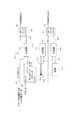
[0037]次に図7を参照すると、本発明の第2の実施形態によるタンデム単一インダクタ、バイポーラ出力ブーストコンバータ701が、DC入力702と、第1の入力スイッチPWMI1 703と、第1の入力スイッチ電流ISW1 730と、第1の接地スイッチPWMG1 708と、第1の負出力ダイオード704と、第1の負出力ダイオード電流IDN1 731と、負出力DC電圧705と、負出力コンデンサ707と、インダクタ706と、第1の正出力ダイオード709と、第1の正出力ダイオード電流732と、正出力DC電圧710と、正出力コンデンサ711と、第2の入力スイッチPWMI2 723と、第2の入力スイッチ電流ISW2 733と、第2の接地スイッチPWMG2 728と、第2の負出力ダイオード724と、第2の負出力ダイオード電流IDN2 734と、第2の正出力ダイオード729と、第2の正出力ダイオード電流735と、接地端子713とを含む。構成要素702、703、704、705、706、707、708、709、710、及び711が、第1の単一インダクタ、バイポーラ出力ブーストコンバータを構成する。構成要素723、724、705、726、707、728、729、710、及び711が、第2の単一インダクタ、バイポーラ出力ブーストコンバータを構成する。構成要素702、705、707、710、及び711は、2つのコンバータに共有される。好ましい動作モードは、各コンバータが、単一インダクタ、バイポーラ出力ブーストコンバータに関して説明したように1サイクルモードで動作するものである。しかし、第2のコンバータのスイッチのタイミングは、1サイクルPWM期間の半分だけ第1のコンバータに対して遅延され、それにより、インダクタ706及び726は、異なる時間に充電及び放電される。このモードの利点は、正出力電圧+VDC705又は814と、負出力電圧−VDC710又は815とに関する図8でのプロットに現れる。より高いリップル周波数が出力に現れ、これは、2つの出力に現れるリップル電圧をフィルタするのに必要とされるコンデンサのサイズを低減する。また、構成要素電流性能の大幅な削減も実現される。ここで、タンデムブーストコンバータ701の各トランジスタスイッチ、ダイオード、及びインダクタは、等価な非タンデム、単一インダクタ、バイポーラ出力ブーストコンバータ401で生じる電流の半分を搬送する。したがって、タンデム単一インダクタ、バイポーラ出力ブーストコンバータ701を実装するのに、より広範囲のより安価な構成要素を使用することができる。図7に示されるタンデムブーストコンバータ段階の数(2)を、望みに応じて、4又は8、又はさらにそれよりも多い複数のコンバータ段階に増加させることができることを当業者は理解されよう。各段階が、図7に示されるようにDC入力端子と、負DC出力端子と、正DC出力端子とに結合される。タンデムブーストコンバータ701に対する代替入力接続は、スイッチPWMG1 708及びPWMG2 728を負の入力源に接続し、スイッチPWMI1 703及びPWMI2 728を接地713に接続することによって当業者が実施することができ、負の入力電圧を利用する単一インダクタコンバータが得られる。第1のダイオード704、第2のダイオード709、第3のダイオード724、及び第4のダイオード729は、正出力710と負出力705との両方に関する同期整流を実施するために、スイッチで置き換えることができる。スイッチ及びダイオード電流の相対タイミングは、タンデムブーストコンバータ701の基本動作を変えることなく、システム全体の効率を最適化するように当業者が調節することができる。 [0037] Referring now to FIG. 7, a tandem single inductor, bipolar
[0038]次に図8を参照すると、本発明の第1の実施形態による2サイクルモードで動作する単一インダクタ、バイポーラ出力ブーストコンバータのタイミング図501が、信号PWMI1 802と、PWMG1 803と、第1のスイッチ電流ISW1 804と、第1のインダクタ電流IL1 805と、第1の正出力ダイオード電流IDP1 806と、第1の負出力ダイオード電流IDN1 807と、信号PWMI1 808と、PWMG1 809と、第2のスイッチ電流ISW1 810と、第2のインダクタ電流IL1 811と、第2の正出力ダイオード電流IDP1 812と、第2の負出力ダイオード電流IDN1 813と、正DC出力電圧+VDC814と、負DC出力電圧−VDC815とに関する波形を含む。信号及びそれらの関係の説明は、図7に関する記述で与えられる。タイミング図801は、1つの可能な結果を示し、基本的な回路挙動を変えずに相対タイミング及び信号レベルスケールを広範囲にわたって調節することができることを当業者は理解されよう。ブーストコンバータ701の第1のインダクタ706及び第2のインダクタ726は、記録波形805によって示されるように連続モードで動作することができる。また、タンデムブーストコンバータ701の第1のインダクタ706及び第2のインダクタ726が、文献で規定される不連続モードで動作することもできることを当業者は理解されよう。 [0038] Referring now to FIG. 8, a timing diagram 501 of a single inductor, bipolar output boost converter operating in a two-cycle mode according to a first embodiment of the present invention includes
[0039]次に図9を参照すると、本発明の第1の実施形態によるブーストコンバータのインダクタ電流間接測定システム901が、DC入力902と、入力スイッチPWMI903と、接地スイッチPWMG909と、負出力ダイオード905と、負出力DC電圧906と、負出力コンデンサ908と、インダクタ907と、正出力ダイオード911と、正出力DC電圧912と、正出力コンデンサ913と、インダクタ電流IL914と、インダクタ正電圧VLP904と、インダクタ負電圧VLN910と、接地端子915とを含み、それら全てが、単一インダクタ、バイポーラブーストコンバータ940を形成し、さらにシステム901が、ADC920と、ADC出力921と、デジタル計算プロセス922と、スイッチ制御入力PWMI 932と、スイッチ制御入力PWMG933と、計算後のインダクタ入力電流930と、計算後のインダクタ出力電流931とを含む。単一インダクタ、バイポーラブーストコンバータ940は、前述したように1サイクル又は2サイクルモードで動作する。ADC920は、VLP904及びVLN910での電圧を測定して、減算し、その結果を、ADC出力921でのデジタルコードに変換する。コードは、ADCデータ変換時の、インダクタ907の両端間の電圧を表す。信号PWMI932は、スイッチPWMI903が閉じられるときにアクティブである。信号PWMG933は、スイッチPWMG909が閉じられるときにアクティブである。デジタル計算プロセス922は、両方のPWMI932及びPWMG933が同時にアクティブである時間を、インダクタ907の充電時間として測定する。次いで、計算プロセス922が、充電時間中にADC920によって測定される平均電圧を検出する。計算プロセス922は、測定されたインダクタ電圧に充電時間を乗算し、インダクタ907の既知の値で除算する。この計算の結果は、インダクタ907を通る最大電流IL914である。電流は鋸歯状波形であるので、平均電流は、ピークインダクタ電流IL914を係数2で除算し、次いで、1サイクルに関する充電時間と非充電時間との総計で充電時間を除算した値を乗算することによって計算される。この結果は、インダクタ入力電流930である。1動作サイクルのうち、インダクタが充電していない時間が、非充電時間である。次いで、計算プロセス922は、非充電時間中にADC920によって測定された平均電圧を検出する。計算プロセス922は、測定されたインダクタ電圧に非充電時間を乗算し、インダクタ907の既知の値で除算する。この計算の結果は、インダクタ907を通る最大電流IL914である。電流は鋸歯状波形であるので、平均電流は、ピークインダクタ電流IL914を係数2で除算し、次いで、1サイクルに関する充電時間と非充電時間との総計で非充電時間を除算した値を乗算することによって計算される。この結果は、インダクタ出力電流931である。ADC及びデジタル計算プロセスを実施することができる多くの方法が存在する。ADC920及びデジタル計算プロセス922に関して定義される処理の幾らか又は全てを、アナログ信号、サンプル値アナログ信号、又はデジタル信号、及びそれらの任意の組合せによって実施することができることを当業者は理解されよう。ADC出力信号921は、パラレルデジタルワード、デジタルビットストリーム、或いは一連のサンプル値アナログ電圧又は電流であってよい。 [0039] Referring now to FIG. 9, a boost converter inductor current
[0040]次に図10を参照すると、従来技術による多相出力バックコンバータ1001が、正DC高電圧入力1002と、負DC高電圧入力1003と、第1の正スイッチ1010と、第1の負スイッチ1011と、第1のインダクタ1012と、第1のコンデンサ1014と、出力L1 1013と、第2の正スイッチ1020と、第2の負スイッチ1021と、第2のインダクタ1022と、第2のコンデンサ1024と、出力L2 1023と、第3の正スイッチ1030と、第3の負スイッチ1031と、第3のインダクタ1032と、第3のコンデンサ1034と、出力L3 1033とを含む。正DC高電圧入力1002と、負DC高電圧入力1003と、第1の正スイッチ1010と、第1の負スイッチ1011と、第1のインダクタ1012と、第1のコンデンサ1014と、出力L1 1013とが、従来技術による単一バックコンバータを構成する。他の2つの出力L2 1023及びL3 1033に関連付けられる回路は、従来技術による2つの同様のバックコンデンサである。3つのコンバータは、L1 1013、L2 1023、及びL3 1033で得られる波形が互いに異なる位相となるようなスイッチタイミングで動作する。インダクタ1012、1022、及び1032と、コンデンサ1014、1024、及び1034とは、スイッチ1010、1011、1020、1021、1030、及び1031によって発生されるスイッチング波形に対してフィルタリングを行うために使用される。インダクタでの電流は、短時間平均、又はDCと、高周波効果との組合せである。 [0040] Referring now to FIG. 10, a prior art multiphase
[0041]次に図11を参照すると、本発明の第1の実施形態によるバックコンバータのインダクタ電流測定システム1101が、正DC高電圧入力1102と、負DC高電圧入力1105と、正スイッチ1103と、負スイッチ1104と、インダクタ1107と、コンデンサ1109と、出力1108と、インダクタ入力電圧1106と、ADC1120と、ADC出力1121と、デジタル低域フィルタ1122と、測定後の短時間平均インダクタ電流出力1123とを含む。正DC高電圧入力1102と、負DC高電圧入力1105と、正スイッチ1103と、負スイッチ1104と、インダクタ1107と、コンデンサ1109と、出力1108と、インダクタ入力電圧1106とが、多相出力バックコンバータの一部として使用することができる単一バックコンバータ段階を構成する。ADC1120は、インダクタ入力1106及び出力1108で測定された電圧を減算することによって、インダクタ1107の両端間の電圧を継続的に測定する。ADCは、インダクタ1107電圧を、ADC出力1121での等価なデジタル信号に変換する。デジタル低域フィルタ1122は、高周波スイッチング効果を除去し、その出力1123で、短時間平均を生じる。この出力は、インダクタ1107の両端間の短時間平均電圧の表現である。この出力を、インダクタ1107の既知のDC抵抗によって除算して、インダクタ1107を通る電流を計算することができる。ADC1120及びデジタル計算プロセス1122に関して定義される処理の幾らか又は全てを、アナログ信号、サンプル値アナログ信号、又はデジタル信号、及びそれらの任意の組合せによって実施することができることを当業者は理解されよう。ADC出力信号1121は、パラレルデジタルワード、デジタルビットストリーム、或いは一連のサンプル値アナログ電圧又は電流であってよい。 [0041] Referring now to FIG. 11, a buck converter inductor
[0042]次に図12を参照すると、従来技術によるデジタルパルス幅変調発生器1201が、パルス幅データ入力1202と、クロック入力1203と、マルチビットカウンタ1209と、カウンタ出力1204と、3つのデータ比較器1205、1212、及び1218と、3つのデータ比較器出力1206、1213、及び1219と、2つのRSフリップフロップ1207及び1214と、データ定数1 1216と、データ定数1の出力1217と、最大カウント定数1210と、最大カウント出力1211と、PWM出力1208と、PWMクロック出力1215とを含む。マルチビットカウンタ1209と、RSフリップフロップ1207及び1214とがリセットされていると仮定すると、システムの初期状態は、カウンタ出力1204がゼロであり、PWM出力1208がアサートされ、且つPWMクロック出力がアサートされるというものである。クロック入力1203でのクロックパルスの連続ストリームの印加により、カウンタ出力が、各クロックパルスで値1だけ増分する。このプロセスは、カウンタ出力1204がパルス幅データ入力1202と等しいことをデータ比較器1205が検出するまで続き、次いで比較器出力1206がアサートされ、RSフリップフロップ1207のリセット、及びPWM出力1208の対応するアサート解除を生じる。したがって、PWM出力1208でのアサートされるパルスの幅は、パルス幅データ入力に、クロック入力1203での信号の期間を乗算した値によって定義される。カウンタ1209は、カウンタ出力1204が最大カウント定数出力1211での最大カウント値と等しいことを比較器1212が検出するまで、その出力1204を増分し続け、次いで比較器1212の出力1213をアサートして、カウンタ1209及び1組のRSフリップフロップ1207及び1214のリセットを生じる。この点で、PWM出力1208とPWMクロック出力1215とがアサートされる。次いで、カウントサイクルが繰り返される。カウンタ出力1204が、定数1の出力1217を介する定数1 1216に等しいときは常に、比較的1218が、その出力1219をアサートし、RSフリップフロップ1214をリセットし、PWMクロック出力1215のアサート解除を生じる。したがって、PWMクロック出力1215は、1入力クロックサイクルごとにアサートされる。PWMクロック出力1215は、ハンドシェイク信号として使用されて、その関連のドライブ回路から、パルス幅データ1202の更新値を要求する。PWM出力1208とPWMクロック出力1215との両方の総期間は、最大カウント定数1210と、クロック入力1203での信号の期間との積に等しい。PWM出力1208のパルス幅は、最小アサート時間が0であり、最大アサート時間が、PWM出力1208の期間である。PWM出力1208の幅の分解能は、クロック入力1203での信号の期間に制限される。実際の状況では、この分解能は、低歪PWM発生波形の要件を満たすには不十分であり、クロック入力1203の周波数、最大カウント定数1210の値、及びマルチビットカウンタ1209のビット数を増加することによってのみ改良することができ、回路寸法、電力消費、及び全体の精度要件の増加をもたらす。デジタル回路を利用して本質的に同じ入力及び出力端子特性を有する、従来技術でのデジタルパルス幅変調器を実装する多くの異なる方法が存在する。 [0042] Referring now to FIG. 12, a digital pulse
[0043]次に図13を参照すると、本発明の一実施形態によるデルタシグマパルス幅変調器1301が、パルス幅粗データ入力1302と、パルス幅精データ入力1307と、デジタル加算器1303と、デジタル加算器出力1304と、デジタルデルタシグマ変調器1308と、デジタルデルタシグマ変調器出力1309と、デジタルパルス幅変調器1305と、クロック入力1310と、PWM出力1306とを含む。デジタルPWM発生器1305は、従来技術に関して説明されているのと同様に動作する。デジタルデルタシグマ変調器1308は、多くの形態を取ることができ、従来技術で全て説明されている。パルス幅粗データ1302は、加算器1303で、デルタシグマ変調器出力1309に加算され、加算器出力1304を生じる。加算器出力1304は、デジタルPWM発生器1305へのパルス幅データ入力であり、PWM出力1306で得られるパルス幅を定義する。パルス幅精データ入力1307は、デルタシグマパルス幅変調器1201全体に関する高分解能設定のマルチビット表現である。パルス幅精データ入力1307は、デルタシグマ変調器1308をドライブし、それにより、各PWMクロック1311サイクルでのその出力1309がプラス1(+1)又はマイナス1(−1)となる。その結果、デジタルPWM発生器データ入力1304が、1だけ増分又は減分され、得られるPWM出力1306パルス幅が、パルス幅粗データ入力1302での値に関して、1入力クロック1310サイクルだけ増分又は減分される。デルタシグマ変調器出力1309は、パルス密度変調を使用して符号化され、その際、平均出力は、各状態の回数に、関連の状態値を乗算し、次いで加算し合わせ、検査されたPWMクロック1311サイクルの総数で除算した値として計算される。また、符号化は、デルタシグマ変調器出力1309の高周波数ディザリングによって低周波数分解能を改良するスペクトル整形の特性を有し、これはデルタシグマ変調のよく知られている特性である。この図に示されるPWM発生法を適用した結果は、デジタルPWM発生器1305へのより高い周波数のクロック入力1310を利用することなく、又はPWMクロック1311出力周波数を増加することなく、PWM出力分解能の大幅な同等の改良を実現することである。文献で規定されるようなデルタシグマ変調器1308の多くの可能な実装形態が存在することを当業者は理解されよう。また、パルス幅精データは、アナログ電圧又は電流信号として定義することができ、デルタシグマ変調器1308は、アナログ/デジタル変換を行うように実装される。デルタシグマパルス幅変調器1301によって定義されるプロセス全体を、アナログ信号、サンプル値アナログ信号、デジタル信号、又はアナログ信号とサンプル値アナログ信号とデジタル信号との組合せを使用して実装することができる。パルス幅粗データ入力1302とパルス幅精データ入力1307とを組み合わせて、単一パルス幅入力を形成することができる。また、デルタシグマ変調器は、他のスペクトル整形及び分解能調節機能を実施するために他の変調器タイプによって置き換えることもできる。加算器1303は、アナログ加算器として実装されることがあり、又はデルタシグマ変調器1308の一部として実装することができる。信号1309は、デルタシグマ変調器1038実装のタイプによっては、3つ以上の状態を含むこともある。 [0043] Referring now to FIG. 13, a delta-sigma
[0044]本発明の原理を、その好ましい実施形態で説明して例示してきたが、そのような原理から逸脱することなく、本発明の構成及び詳細を修正することができることが当業者に理解される。好ましい方法及び回路が示されたが、好ましい方法及び回路の正確な詳細は、特定の用途に関して必要とされるように望みに応じて変更することができる。例えば、説明した集積回路の分割は、電力消費及びコストを削減するために、示される機能を包含又は除外することができる。様々な回路ブロック内部、又は様々な回路ブロック間の全ての信号方式は、アナログ、サンプル値アナログ、又はデジタル領域で実装することができる。入力ブーストコンバータと、電荷蓄積素子と、出力バックコンバータとは、回路縮小技法によって単一機能に組み合わせることができる。したがって、本発明者等は、以下の特許請求の範囲の精神及び範囲内に入る全ての修正形態及び変形形態を特許請求する。 [0044] While the principles of the invention have been illustrated and illustrated in preferred embodiments thereof, those skilled in the art will recognize that the configuration and details of the invention can be modified without departing from such principles. The Although preferred methods and circuits have been shown, the exact details of the preferred methods and circuits can be varied as desired as needed for a particular application. For example, the described integrated circuit partitioning may include or exclude the functions shown to reduce power consumption and cost. All signaling schemes within or between various circuit blocks can be implemented in the analog, sampled analog, or digital domain. The input boost converter, charge storage element, and output buck converter can be combined into a single function by circuit reduction techniques. We therefore claim as all modifications and variations that fall within the spirit and scope of the following claims.
Claims (20)
Translated fromJapaneseDC入力端子と、
AC出力端子と、
前記AC出力端子を通して情報を受信及び送信するための通信システムと
を備えるインバータ。An inverter for use in a photovoltaic module,
A DC input terminal;
An AC output terminal;
An inverter comprising: a communication system for receiving and transmitting information through the AC output terminal.
少なくとも前記DC入力端子及び前記AC出力端子での電圧を監視するための監視システムと、
前記DC入力端子と前記AC出力端子との間に結合された電力セクションと、
前記監視システムと前記電力セクションとの間に結合された制御システムと
を備える請求項1に記載のインバータ。further,
A monitoring system for monitoring voltages at least at the DC input terminal and the AC output terminal;
A power section coupled between the DC input terminal and the AC output terminal;
The inverter of claim 1, comprising a control system coupled between the monitoring system and the power section.
DC入力端子と、
負DC出力端子と、
正DC出力端子と、
第1のノード及び第2のノードを有する単一インダクタと、
前記DC入力端子と前記インダクタの前記第1のノードとの間に結合された第1のスイッチと、
接地と前記インダクタの前記第2のノードとの間に結合された第2のスイッチと、
前記負DC出力端子に結合されたアノード、及び前記インダクタの前記第1のノードに結合されたカソードを有する第1のダイオードと、
前記インダクタの前記第2のノードに結合されたアノード、及び前記正DC出力端子に結合されたカソードを有する第2のダイオードと、
前記負DC出力端子に結合された第1のコンデンサと、
前記正DC出力端子に結合された第2のコンデンサと
を備える単一インダクタ、バイポーラ出力ブーストコンバータ。A single inductor, bipolar output boost converter for use in an inverter,
A DC input terminal;
A negative DC output terminal;
A positive DC output terminal;
A single inductor having a first node and a second node;
A first switch coupled between the DC input terminal and the first node of the inductor;
A second switch coupled between ground and the second node of the inductor;
A first diode having an anode coupled to the negative DC output terminal and a cathode coupled to the first node of the inductor;
A second diode having an anode coupled to the second node of the inductor and a cathode coupled to the positive DC output terminal;
A first capacitor coupled to the negative DC output terminal;
A single inductor, bipolar output boost converter comprising a second capacitor coupled to the positive DC output terminal.
DC入力端子と、
負DC出力端子と、
正DC出力端子と、
前記DC入力端子と接地との間で切り替えられる単一インダクタ、前記負DC出力端子に結合された第1の出力、及び前記正DC出力端子に結合された第2の出力を有する第1のブーストコンバータと、
前記DC入力端子と接地との間で切り替えられる単一インダクタ、前記負DC出力端子に結合された第1の出力、及び前記正DC出力端子に結合された第2の出力を有する第2のブーストコンバータと、
前記負DC出力端子に結合された第1のコンデンサと、
前記正DC出力端子に結合された第2のコンデンサと
を備えるタンデムバイポーラ出力ブーストコンバータ。A tandem bipolar output boost converter for use in an inverter,
A DC input terminal;
A negative DC output terminal;
A positive DC output terminal;
A first boost having a single inductor switched between the DC input terminal and ground, a first output coupled to the negative DC output terminal, and a second output coupled to the positive DC output terminal A converter,
A second boost having a single inductor switched between the DC input terminal and ground, a first output coupled to the negative DC output terminal, and a second output coupled to the positive DC output terminal A converter,
A first capacitor coupled to the negative DC output terminal;
A tandem bipolar output boost converter comprising a second capacitor coupled to the positive DC output terminal.
Applications Claiming Priority (3)
| Application Number | Priority Date | Filing Date | Title |
|---|---|---|---|
| US93866307P | 2007-05-17 | 2007-05-17 | |
| US12/121,580US10468993B2 (en) | 2007-05-17 | 2008-05-15 | Inverter for use in photovoltaic module |
| PCT/US2008/063958WO2008144548A2 (en) | 2007-05-17 | 2008-05-16 | Photovoltaic module-mounted ac inverter |
Publications (2)
| Publication Number | Publication Date |
|---|---|
| JP2010527571Atrue JP2010527571A (en) | 2010-08-12 |
| JP2010527571A5 JP2010527571A5 (en) | 2012-04-12 |
Family
ID=40026294
Family Applications (2)
| Application Number | Title | Priority Date | Filing Date |
|---|---|---|---|
| JP2010508612APendingJP2010527571A (en) | 2007-05-17 | 2008-05-16 | Photovoltaic module mounting AC inverter |
| JP2010508614APendingJP2010527572A (en) | 2007-05-17 | 2008-05-16 | Solar power AC inverter installation and interconnection |
Family Applications After (1)
| Application Number | Title | Priority Date | Filing Date |
|---|---|---|---|
| JP2010508614APendingJP2010527572A (en) | 2007-05-17 | 2008-05-16 | Solar power AC inverter installation and interconnection |
Country Status (8)
| Country | Link |
|---|---|
| US (4) | US10468993B2 (en) |
| EP (2) | EP2151036A2 (en) |
| JP (2) | JP2010527571A (en) |
| KR (3) | KR20100017853A (en) |
| AU (2) | AU2008254822B2 (en) |
| CA (2) | CA2691967A1 (en) |
| IL (2) | IL202199A0 (en) |
| WO (2) | WO2008144554A2 (en) |
Cited By (8)
| Publication number | Priority date | Publication date | Assignee | Title |
|---|---|---|---|---|
| JP2012114985A (en)* | 2010-11-22 | 2012-06-14 | Sony Corp | Power relay apparatus, power relay method, power supply control device, power supply control method, and power supply control system |
| WO2012157441A1 (en)* | 2011-05-16 | 2012-11-22 | ソニー株式会社 | Power supply device, method, and program |
| US8325841B2 (en) | 2008-03-23 | 2012-12-04 | Lg Electronics Inc. | Method for transmitting signals for reducing feedback overhead and method for transmitting feedback information for the same |
| JP2013503574A (en)* | 2009-08-28 | 2013-01-31 | エンフェイズ エナジー インコーポレイテッド | Power line communication device |
| JP2014229818A (en)* | 2013-05-24 | 2014-12-08 | ケージーエス株式会社 | String monitor system for photovoltaic power generation |
| KR20160025933A (en)* | 2014-08-28 | 2016-03-09 | 엘지전자 주식회사 | Transformer and power converting apparatus icnluing the same |
| JP2017163787A (en)* | 2016-03-11 | 2017-09-14 | オムロン株式会社 | Power storage system and power conditioner |
| WO2018142543A1 (en)* | 2017-02-02 | 2018-08-09 | 三菱電機株式会社 | Higher harmonic suppression device and higher harmonic suppression system |
Families Citing this family (195)
| Publication number | Priority date | Publication date | Assignee | Title |
|---|---|---|---|---|
| GB2415841B (en)* | 2004-11-08 | 2006-05-10 | Enecsys Ltd | Power conditioning unit |
| US8405367B2 (en) | 2006-01-13 | 2013-03-26 | Enecsys Limited | Power conditioning units |
| GB2434490B (en) | 2006-01-13 | 2009-04-01 | Enecsys Ltd | Power conditioning unit |
| US9088178B2 (en) | 2006-12-06 | 2015-07-21 | Solaredge Technologies Ltd | Distributed power harvesting systems using DC power sources |
| US8963369B2 (en) | 2007-12-04 | 2015-02-24 | Solaredge Technologies Ltd. | Distributed power harvesting systems using DC power sources |
| US8319471B2 (en) | 2006-12-06 | 2012-11-27 | Solaredge, Ltd. | Battery power delivery module |
| US8618692B2 (en) | 2007-12-04 | 2013-12-31 | Solaredge Technologies Ltd. | Distributed power system using direct current power sources |
| US11309832B2 (en) | 2006-12-06 | 2022-04-19 | Solaredge Technologies Ltd. | Distributed power harvesting systems using DC power sources |
| US11888387B2 (en) | 2006-12-06 | 2024-01-30 | Solaredge Technologies Ltd. | Safety mechanisms, wake up and shutdown methods in distributed power installations |
| US11735910B2 (en) | 2006-12-06 | 2023-08-22 | Solaredge Technologies Ltd. | Distributed power system using direct current power sources |
| US11569659B2 (en) | 2006-12-06 | 2023-01-31 | Solaredge Technologies Ltd. | Distributed power harvesting systems using DC power sources |
| US8947194B2 (en) | 2009-05-26 | 2015-02-03 | Solaredge Technologies Ltd. | Theft detection and prevention in a power generation system |
| US8816535B2 (en) | 2007-10-10 | 2014-08-26 | Solaredge Technologies, Ltd. | System and method for protection during inverter shutdown in distributed power installations |
| US8013472B2 (en) | 2006-12-06 | 2011-09-06 | Solaredge, Ltd. | Method for distributed power harvesting using DC power sources |
| US11687112B2 (en) | 2006-12-06 | 2023-06-27 | Solaredge Technologies Ltd. | Distributed power harvesting systems using DC power sources |
| US8319483B2 (en) | 2007-08-06 | 2012-11-27 | Solaredge Technologies Ltd. | Digital average input current control in power converter |
| US8384243B2 (en) | 2007-12-04 | 2013-02-26 | Solaredge Technologies Ltd. | Distributed power harvesting systems using DC power sources |
| US11855231B2 (en) | 2006-12-06 | 2023-12-26 | Solaredge Technologies Ltd. | Distributed power harvesting systems using DC power sources |
| US8473250B2 (en) | 2006-12-06 | 2013-06-25 | Solaredge, Ltd. | Monitoring of distributed power harvesting systems using DC power sources |
| US12316274B2 (en) | 2006-12-06 | 2025-05-27 | Solaredge Technologies Ltd. | Pairing of components in a direct current distributed power generation system |
| US7994657B2 (en)* | 2006-12-22 | 2011-08-09 | Solarbridge Technologies, Inc. | Modular system for unattended energy generation and storage |
| US9407093B2 (en) | 2007-08-22 | 2016-08-02 | Maxout Renewables, Inc. | Method for balancing circuit voltage |
| US20090084426A1 (en)* | 2007-09-28 | 2009-04-02 | Enphase Energy, Inc. | Universal interface for a photovoltaic module |
| US7755916B2 (en) | 2007-10-11 | 2010-07-13 | Solarbridge Technologies, Inc. | Methods for minimizing double-frequency ripple power in single-phase power conditioners |
| CN105244905B (en) | 2007-12-05 | 2019-05-21 | 太阳能安吉有限公司 | Release mechanism in distributed power device is waken up and method for closing |
| US7994762B2 (en)* | 2007-12-11 | 2011-08-09 | Analog Devices, Inc. | DC to DC converter |
| EP2235807B1 (en) | 2007-12-20 | 2019-05-08 | SolarCity Corporation | Grid synchronisation |
| US9263895B2 (en)* | 2007-12-21 | 2016-02-16 | Sunpower Corporation | Distributed energy conversion systems |
| US20100326490A1 (en)* | 2008-01-09 | 2010-12-30 | Tagliareni Russell V | Photovoltaic panel with hot plug connector |
| US8383943B2 (en)* | 2008-03-28 | 2013-02-26 | Greenray, Inc. | Electrical cable harness and assembly for transmitting AC electrical power |
| EP2294669B8 (en) | 2008-05-05 | 2016-12-07 | Solaredge Technologies Ltd. | Direct current power combiner |
| US8023266B2 (en)* | 2008-05-20 | 2011-09-20 | Greenray Inc. | AC photovoltaic module and inverter assembly |
| JP2011529322A (en)* | 2008-06-03 | 2011-12-01 | ソーラー・レッド・インコーポレーテッド | Solar collector mounting system |
| US8406019B2 (en)* | 2008-09-15 | 2013-03-26 | General Electric Company | Reactive power compensation in solar power system |
| US8143862B2 (en)* | 2009-03-12 | 2012-03-27 | 02Micro Inc. | Circuits and methods for battery charging |
| WO2010111412A2 (en)* | 2009-03-24 | 2010-09-30 | Infinirel Corporation | Systems, devices and methods for predicting power electronics failure |
| US8435056B2 (en)* | 2009-04-16 | 2013-05-07 | Enphase Energy, Inc. | Apparatus for coupling power generated by a photovoltaic module to an output |
| FR2944924A1 (en)* | 2009-04-23 | 2010-10-29 | Francecol Technology S A R L | ELECTRIC POWER MANAGEMENT SYSTEM BY MODULAR ELECTRONIC VARIATOR |
| CN102460338B (en) | 2009-05-19 | 2014-08-13 | 最大输出可再生能源公司 | Construction of a power station comprising a cluster of power generating units |
| US8217534B2 (en)* | 2009-05-20 | 2012-07-10 | General Electric Company | Power generator distributed inverter |
| WO2011002261A2 (en)* | 2009-07-02 | 2011-01-06 | 주식회사 탑선 | Solar energy ac generating apparatus |
| CA2767867C (en)* | 2009-07-16 | 2018-11-13 | General Cybernation Group, Inc. | Smart and scalable power inverters |
| US8482947B2 (en) | 2009-07-31 | 2013-07-09 | Solarbridge Technologies, Inc. | Apparatus and method for controlling DC-AC power conversion |
| US8558102B2 (en)* | 2009-09-11 | 2013-10-15 | Miasole | Rotatable junction box for a solar module |
| US8207637B2 (en)* | 2009-10-09 | 2012-06-26 | Solarbridge Technologies, Inc. | System and apparatus for interconnecting an array of power generating assemblies |
| US8462518B2 (en) | 2009-10-12 | 2013-06-11 | Solarbridge Technologies, Inc. | Power inverter docking system for photovoltaic modules |
| US12418177B2 (en) | 2009-10-24 | 2025-09-16 | Solaredge Technologies Ltd. | Distributed power system using direct current power sources |
| US8824178B1 (en) | 2009-12-31 | 2014-09-02 | Solarbridge Technologies, Inc. | Parallel power converter topology |
| EP2529450A4 (en) | 2010-01-25 | 2014-10-22 | Enphase Energy Inc | Method and apparatus for interconnecting distributed power sources |
| US9806445B2 (en) | 2010-01-25 | 2017-10-31 | Enphase Energy, Inc. | Method and apparatus for interconnecting distributed power sources |
| US8564916B2 (en)* | 2010-02-16 | 2013-10-22 | Western Gas And Electric Company | Photovoltaic array ground fault detection method for utility-scale grounded solar electric power generating systems |
| US8618456B2 (en)* | 2010-02-16 | 2013-12-31 | Western Gas And Electric Company | Inverter for a three-phase AC photovoltaic system |
| IT1398473B1 (en)* | 2010-02-23 | 2013-03-01 | Aparo D | SYSTEM FOR THE NON-LINEAR CONTROL OF DC-AC CONVERTERS. |
| JP5453158B2 (en)* | 2010-04-12 | 2014-03-26 | シャープ株式会社 | Photovoltaic power generation system, power converter, and current collection box |
| CN101958351B (en)* | 2010-04-20 | 2013-05-15 | 常州天合光能有限公司 | Solar cell module with multiple junction boxes |
| GB2482653B (en) | 2010-06-07 | 2012-08-29 | Enecsys Ltd | Solar photovoltaic systems |
| KR101448655B1 (en)* | 2010-06-23 | 2014-10-08 | 엘지전자 주식회사 | Power factor correction circuit for lighting and driving method thereof |
| US8772965B2 (en)* | 2010-06-29 | 2014-07-08 | General Electric Company | Solar power generation system and method |
| US20130298962A1 (en)* | 2010-07-12 | 2013-11-14 | Jerry Sorgento | Portable modular solar energy power generating system |
| US8455752B2 (en)* | 2010-07-29 | 2013-06-04 | General Electric Company | Integral ac module grounding system |
| EP2418687A1 (en)* | 2010-08-12 | 2012-02-15 | Matteo Alvisi | Photovoltaic panel comprising an inverter |
| CN102377365A (en)* | 2010-08-13 | 2012-03-14 | 无锡尚德太阳能电力有限公司 | Intelligent photovoltaic component and photovoltaic system |
| USD666974S1 (en) | 2010-09-24 | 2012-09-11 | Solarbridge Technologies, Inc. | Y-junction interconnect module |
| US9350166B2 (en) | 2010-10-05 | 2016-05-24 | Alencon Acquisition Co., Llc | High voltage energy harvesting and conversion renewable energy utility size electric power systems and visual monitoring and control systems for said systems |
| US9118215B2 (en) | 2010-10-05 | 2015-08-25 | Alencon Acquistion Co., Llc | High voltage energy harvesting and conversion renewable energy utility size electric power systems and visual monitoring and control systems for said systems |
| WO2012155126A2 (en)* | 2011-05-12 | 2012-11-15 | Alencon Acquisition Co., Llc | High voltage energy harvesting and conversion renewable energy utility size electric power systems and visual monitoring and control systems |
| US8503200B2 (en) | 2010-10-11 | 2013-08-06 | Solarbridge Technologies, Inc. | Quadrature-corrected feedforward control apparatus and method for DC-AC power conversion |
| US9160408B2 (en)* | 2010-10-11 | 2015-10-13 | Sunpower Corporation | System and method for establishing communication with an array of inverters |
| US8279649B2 (en) | 2010-10-11 | 2012-10-02 | Solarbridge Technologies, Inc. | Apparatus and method for controlling a power inverter |
| GB2485527B (en) | 2010-11-09 | 2012-12-19 | Solaredge Technologies Ltd | Arc detection and prevention in a power generation system |
| US10673229B2 (en) | 2010-11-09 | 2020-06-02 | Solaredge Technologies Ltd. | Arc detection and prevention in a power generation system |
| JP5487084B2 (en)* | 2010-11-19 | 2014-05-07 | 株式会社メガチップス | Power supply |
| US9118213B2 (en) | 2010-11-24 | 2015-08-25 | Kohler Co. | Portal for harvesting energy from distributed electrical power sources |
| US9467063B2 (en) | 2010-11-29 | 2016-10-11 | Sunpower Corporation | Technologies for interleaved control of an inverter array |
| US8842454B2 (en) | 2010-11-29 | 2014-09-23 | Solarbridge Technologies, Inc. | Inverter array with localized inverter control |
| GB2483317B (en) | 2011-01-12 | 2012-08-22 | Solaredge Technologies Ltd | Serially connected inverters |
| GB2487368B (en) | 2011-01-18 | 2012-12-05 | Enecsys Ltd | Inverters |
| US8937465B2 (en)* | 2011-02-11 | 2015-01-20 | Alcatel Lucent | Active voice band noise filter |
| US9093902B2 (en)* | 2011-02-15 | 2015-07-28 | Cyboenergy, Inc. | Scalable and redundant mini-inverters |
| GB2486032B (en)* | 2011-03-22 | 2013-06-19 | Enecsys Ltd | Solar photovoltaic inverters |
| DE102011015327B4 (en)* | 2011-03-28 | 2023-04-27 | Sew-Eurodrive Gmbh & Co Kg | Converter arrangement, method for producing a converter arrangement and method for operating a converter arrangement |
| WO2012149274A1 (en)* | 2011-04-27 | 2012-11-01 | Solarbridge Technologies, Inc. | Method and system for controlling a multi-stage power inverter |
| US9065354B2 (en) | 2011-04-27 | 2015-06-23 | Sunpower Corporation | Multi-stage power inverter for power bus communication |
| US8193788B2 (en) | 2011-04-27 | 2012-06-05 | Solarbridge Technologies, Inc. | Method and device for controlling a configurable power supply to provide AC and/or DC power output |
| US8611107B2 (en) | 2011-04-27 | 2013-12-17 | Solarbridge Technologies, Inc. | Method and system for controlling a multi-stage power inverter |
| US11901810B2 (en) | 2011-05-08 | 2024-02-13 | Koolbridge Solar, Inc. | Adaptive electrical power distribution panel |
| US10090777B2 (en) | 2011-05-08 | 2018-10-02 | Koolbridge Solar, Inc. | Inverter with independent current and voltage controlled outputs |
| US8937822B2 (en) | 2011-05-08 | 2015-01-20 | Paul Wilkinson Dent | Solar energy conversion and utilization system |
| US12362647B2 (en) | 2011-05-08 | 2025-07-15 | Koolbridge Solar, Inc. | Solar energy system with variable priority circuit backup |
| US11460488B2 (en) | 2017-08-14 | 2022-10-04 | Koolbridge Solar, Inc. | AC electrical power measurements |
| CH705107A2 (en)* | 2011-06-03 | 2012-12-14 | Huber+Suhner Ag | Modular solar cell. |
| KR101063208B1 (en)* | 2011-06-09 | 2011-09-07 | 이앤에이치(주) | Building integrated solar power unit with micro inverter |
| US8994218B2 (en) | 2011-06-10 | 2015-03-31 | Cyboenergy, Inc. | Smart and scalable off-grid mini-inverters |
| US9331488B2 (en) | 2011-06-30 | 2016-05-03 | Cyboenergy, Inc. | Enclosure and message system of smart and scalable power inverters |
| US8922185B2 (en) | 2011-07-11 | 2014-12-30 | Solarbridge Technologies, Inc. | Device and method for global maximum power point tracking |
| WO2013012852A1 (en) | 2011-07-18 | 2013-01-24 | Enphase Energy, Inc. | Resilient mounting assembly for photovoltaic modules |
| US8922972B2 (en)* | 2011-08-12 | 2014-12-30 | General Electric Company | Integral module power conditioning system |
| US8422249B2 (en) | 2011-08-25 | 2013-04-16 | Direct Grid Technologies, LLC | Apparatus for a microinverter particularly suited for use in solar power installations |
| US8284574B2 (en) | 2011-10-17 | 2012-10-09 | Solarbridge Technologies, Inc. | Method and apparatus for controlling an inverter using pulse mode control |
| TWI458228B (en)* | 2011-10-26 | 2014-10-21 | Acbel Polytech Inc | Soft start control method and device for power supply |
| KR101854395B1 (en)* | 2011-11-25 | 2018-05-08 | 한국전자통신연구원 | Power control driving device and method thereof |
| TW201328118A (en)* | 2011-12-28 | 2013-07-01 | Hon Hai Prec Ind Co Ltd | Uninterruptible power supply system |
| US20130169056A1 (en)* | 2011-12-28 | 2013-07-04 | Miasole | Multi-module inverters and converters for building integrable photovoltaic modules |
| CN102565586B (en)* | 2012-01-06 | 2014-06-04 | 西安龙腾新能源科技发展有限公司 | Automatic identification method of number of photovoltaic modules |
| GB2498365A (en) | 2012-01-11 | 2013-07-17 | Solaredge Technologies Ltd | Photovoltaic module |
| GB2498790A (en) | 2012-01-30 | 2013-07-31 | Solaredge Technologies Ltd | Maximising power in a photovoltaic distributed power system |
| GB2498791A (en) | 2012-01-30 | 2013-07-31 | Solaredge Technologies Ltd | Photovoltaic panel circuitry |
| US9853565B2 (en) | 2012-01-30 | 2017-12-26 | Solaredge Technologies Ltd. | Maximized power in a photovoltaic distributed power system |
| US8962998B2 (en)* | 2012-02-08 | 2015-02-24 | Shoals Technologies Group, Llc | Solar panel junction box capable of integrating with a variety of accessory modules, and method of use |
| US20130293021A1 (en)* | 2012-05-01 | 2013-11-07 | Rajiv Kumar Varma | Enhanced utilization of real power generating capacity of distributed generator (dg) inverters as statcom |
| KR20130128700A (en)* | 2012-05-17 | 2013-11-27 | 현대모비스 주식회사 | Apparatus and method for maintaining constant voltage |
| USD707632S1 (en) | 2012-06-07 | 2014-06-24 | Enphase Energy, Inc. | Trunk connector |
| USD708143S1 (en) | 2012-06-07 | 2014-07-01 | Enphase Energy, Inc. | Drop cable connector |
| US9276635B2 (en) | 2012-06-29 | 2016-03-01 | Sunpower Corporation | Device, system, and method for communicating with a power inverter using power line communications |
| CN102810582B (en) | 2012-08-14 | 2015-04-22 | 友达光电股份有限公司 | Solar installation and its frame combination |
| US9948139B2 (en) | 2012-10-26 | 2018-04-17 | Solpad, Inc. | Solar power generation, distribution, and communication system |
| US9444397B2 (en) | 2012-10-26 | 2016-09-13 | Sunculture Solar, Inc. | Integrated solar panel |
| US10122320B2 (en)* | 2012-10-26 | 2018-11-06 | Sunculture Solar, Inc. | Solar panel personality engine |
| US9620993B2 (en) | 2012-10-26 | 2017-04-11 | Solpad, Inc. | Auto-synchronous isolated inlet power converter |
| USD734653S1 (en) | 2012-11-09 | 2015-07-21 | Enphase Energy, Inc. | AC module mounting bracket |
| US20140153303A1 (en)* | 2012-11-30 | 2014-06-05 | SunEdison Microinverter Products LLC | Solar module having a back plane integrated inverter |
| US9438042B2 (en)* | 2013-02-19 | 2016-09-06 | General Electric Company | Direct current power delivery system and method |
| JP6082886B2 (en)* | 2013-02-22 | 2017-02-22 | 株式会社高砂製作所 | Power adjustment apparatus and power adjustment method |
| US9548619B2 (en) | 2013-03-14 | 2017-01-17 | Solaredge Technologies Ltd. | Method and apparatus for storing and depleting energy |
| EP2973743A2 (en)* | 2013-03-15 | 2016-01-20 | SunCulture Solar Inc. | Integrated solar panel |
| US9584044B2 (en) | 2013-03-15 | 2017-02-28 | Sunpower Corporation | Technologies for converter topologies |
| US10833629B2 (en)* | 2013-03-15 | 2020-11-10 | Technology Research, Llc | Interface for renewable energy system |
| US9564835B2 (en)* | 2013-03-15 | 2017-02-07 | Sunpower Corporation | Inverter communications using output signal |
| US9564756B2 (en) | 2013-03-15 | 2017-02-07 | Technology Research, Llc | Interface for renewable energy system |
| US9231476B2 (en)* | 2013-05-01 | 2016-01-05 | Texas Instruments Incorporated | Tracking energy consumption using a boost-buck technique |
| WO2014182802A1 (en)* | 2013-05-07 | 2014-11-13 | University Of Central Florida Research Foundation, Inc. | Photovoltaic (pv)-based ac module and solar systems therefrom |
| DE102013104940A1 (en)* | 2013-05-14 | 2014-11-20 | Norbert Danneberg | converter circuit |
| KR20150030078A (en)* | 2013-09-11 | 2015-03-19 | 엘에스산전 주식회사 | Photovoltaic inverter |
| CN103595074B (en)* | 2013-11-26 | 2016-08-17 | 北京国电通网络技术有限公司 | The system that a kind of intelligence is run from combining inverter integration |
| AU2014354752B2 (en) | 2013-11-27 | 2018-12-13 | Patrick L. Chapman | Integration of microinverter with photovoltaic module |
| US9343600B2 (en) | 2013-12-06 | 2016-05-17 | Haibo Zhang | Integrated microinverter housing for a PV AC module |
| US20150188249A1 (en)* | 2013-12-31 | 2015-07-02 | Fabio Pereira | Ac cable assembly interconnection technologies for microinverter array |
| WO2015103389A1 (en)* | 2014-01-02 | 2015-07-09 | Enphase Energy, Inc. | Portable solar panel kit |
| EP3097431B1 (en)* | 2014-01-23 | 2021-11-03 | Saab AB | Radar system with a switching mode dc/dc power converter for delivering a direct current to a pulse radar unit |
| KR102193871B1 (en)* | 2014-01-28 | 2020-12-22 | 엘지전자 주식회사 | Integral inverter and solar cell module including the same |
| AU2015253190A1 (en)* | 2014-04-29 | 2016-11-17 | Solpad, Inc. | Auto-synchronous isolated inlet power converter |
| US9584038B2 (en) | 2014-06-02 | 2017-02-28 | Enphase Energy, Inc. | Ungrounded inverter enclosure and cabling |
| US10033302B2 (en) | 2014-08-29 | 2018-07-24 | Koolbridge Solar, Inc. | Rotary solar converter |
| CN104300575A (en)* | 2014-09-11 | 2015-01-21 | 国家电网公司 | A low-power distributed photovoltaic power generation system combined with energy storage batteries |
| US10505370B2 (en)* | 2014-09-30 | 2019-12-10 | Sungrow Power Supply Co., Ltd. | Safety detection device and method of grid-connected inverter |
| US20170338659A1 (en)* | 2014-10-28 | 2017-11-23 | Sinewatts, Inc. | Systems and methods for dispatching maximum available capacity for photovoltaic power plants |
| AU2015364718B2 (en) | 2014-12-16 | 2019-11-28 | Marici Holdings The Netherlands B.V. | Energy panel arrangement power dissipation |
| WO2016123305A1 (en) | 2015-01-28 | 2016-08-04 | Abb Technology Ag | Energy panel arrangement shutdown |
| US9906038B2 (en)* | 2015-01-29 | 2018-02-27 | Cyboenergy, Inc. | Smart renewable power generation system with grid and DC source flexibility |
| US9876360B2 (en) | 2015-02-02 | 2018-01-23 | Technology Research, Llc | Interface for renewable energy system |
| WO2016134356A1 (en) | 2015-02-22 | 2016-08-25 | Abb Technology Ag | Photovoltaic string reverse polarity detection |
| US10765015B2 (en)* | 2015-03-13 | 2020-09-01 | Enphase Engery, Inc. | Bulkhead interface and cable connector |
| CN104767431B (en)* | 2015-04-02 | 2018-08-28 | 上海晶丰明源半导体股份有限公司 | A kind of control method, the device and system of the modulation of DC brushless motor pulse width |
| CN106160176A (en)* | 2015-04-28 | 2016-11-23 | 台达电子企业管理(上海)有限公司 | Power Distribution Systems and Electrical Systems |
| US10148216B2 (en) | 2015-06-11 | 2018-12-04 | Darfon Electronics Corp. | Package of a supporting device for photovoltaic panels and kit for forming a supporting device for at least one photovoltaic panel |
| US10148093B2 (en) | 2015-06-16 | 2018-12-04 | Koolbridge Solar, Inc. | Inter coupling of microinverters |
| US11056997B2 (en) | 2015-06-27 | 2021-07-06 | Sunpower Corporation | Universal photovoltaic laminate |
| US10686316B2 (en)* | 2015-10-09 | 2020-06-16 | LT Lighting (Taiwan) Corp. | Controlled energy storage balance technology |
| SE539911C2 (en)* | 2015-11-18 | 2018-01-09 | Optistring Tech Ab | Common line communication in cascaded inverters |
| AR107145A1 (en) | 2015-12-18 | 2018-03-28 | Southwire Co Llc | CURRENT INVERSORS OF SOLAR CELLS INTEGRATED TO A CABLE |
| CN105553072B (en)* | 2015-12-21 | 2018-04-10 | 北京空间飞行器总体设计部 | A kind of multiphase digital electric discharge adjusting method suitable for spacecraft power supply system |
| DE102015122636B4 (en)* | 2015-12-22 | 2017-07-13 | Sma Solar Technology Ag | Inverter with mains separation point and insulation resistance measurement as well as method for measuring an insulation resistance |
| US9991682B2 (en)* | 2016-01-21 | 2018-06-05 | Nextek Power Systems, Inc. | Hot-swappable system for and method of distributing electrical power and/or data to at least one electrical device |
| US11143163B2 (en) | 2016-03-08 | 2021-10-12 | Semtive Inc. | Vertical axis wind turbine |
| DE102016105477A1 (en) | 2016-03-23 | 2017-09-28 | Solarworld Ag | photovoltaic module |
| US11018623B2 (en) | 2016-04-05 | 2021-05-25 | Solaredge Technologies Ltd. | Safety switch for photovoltaic systems |
| US11177663B2 (en)* | 2016-04-05 | 2021-11-16 | Solaredge Technologies Ltd. | Chain of power devices |
| US12057807B2 (en) | 2016-04-05 | 2024-08-06 | Solaredge Technologies Ltd. | Chain of power devices |
| US10483759B2 (en) | 2016-04-07 | 2019-11-19 | Alencon Acquisition Co., Llc | Integrated multi-mode large-scale electric power support system for an electrical grid |
| US9929665B2 (en)* | 2016-04-20 | 2018-03-27 | International Business Machines Corporation | Remotely controllable modular power control device for power generation |
| US11196272B2 (en) | 2016-06-29 | 2021-12-07 | Koolbridge Solar, Inc. | Rapid de-energization of DC conductors with a power source at both ends |
| CN106129162A (en)* | 2016-07-29 | 2016-11-16 | 无锡嘉瑞光伏有限公司 | A kind of solar battery sheet and assembly and preparation technology thereof |
| CN106301201B (en)* | 2016-10-19 | 2021-01-12 | 丰郅(上海)新能源科技有限公司 | Power optimization circuit integrating data communication function and communication method |
| EP3535825A1 (en) | 2016-11-07 | 2019-09-11 | Southwire Company, LLC | Dead band direct current converter |
| CN108258718B (en)* | 2016-12-29 | 2021-01-26 | 北京天诚同创电气有限公司 | Inverter, distributed combiner box, power limiting control system and method |
| US11251621B1 (en) | 2017-08-03 | 2022-02-15 | Southwire Company, Llc | Solar power generation system |
| US11438988B1 (en) | 2017-08-11 | 2022-09-06 | Southwire Company, Llc | DC power management system |
| US10250162B2 (en) | 2017-08-14 | 2019-04-02 | Koolbridge Solar, Inc. | DC bias prevention in transformerless inverters |
| US11228171B2 (en) | 2017-08-14 | 2022-01-18 | Koolbridge Solar, Inc. | Overcurrent trip coordination between inverter and circuit breakers |
| CN107579705B (en)* | 2017-08-15 | 2019-11-05 | 华为数字技术(苏州)有限公司 | A kind of photovoltaic module connection structure |
| EA202091049A1 (en)* | 2017-10-27 | 2020-07-16 | ЭлТи ЛАЙТИНГ (ТАЙВАНЬ) КОРПОРЕЙШН | MANAGED ENERGY STORAGE BALANCING TECHNOLOGY |
| CN108183681A (en)* | 2017-12-30 | 2018-06-19 | 孙振华 | A kind of photovoltaic DC-to-AC converter |
| CN108039767A (en)* | 2017-12-30 | 2018-05-15 | 孙振华 | A kind of photovoltaic power supply system based on novel inverter |
| US11207988B2 (en) | 2018-08-06 | 2021-12-28 | Robert M. Lyden | Electric or hybrid vehicle with wireless device and method of supplying electromagnetic energy to vehicle |
| US10840707B2 (en)* | 2018-08-06 | 2020-11-17 | Robert M. Lyden | Utility pole with solar modules and wireless device and method of retrofitting existing utility pole |
| CN112956124A (en)* | 2018-09-12 | 2021-06-11 | 伊格纳西奥·华雷斯 | Micro inverter and controller |
| US10998730B1 (en) | 2019-04-26 | 2021-05-04 | NeoVolta, Inc. | Adaptive solar power battery storage system |
| US11036581B2 (en)* | 2019-08-08 | 2021-06-15 | Apple Inc. | Non-volatile memory control circuit with parallel error detection and correction |
| KR102333914B1 (en)* | 2019-08-16 | 2021-12-13 | 최창준 | Power Line Communication with Polarity switching |
| US11545931B2 (en) | 2019-11-10 | 2023-01-03 | Maxout Renewables, Inc. | Optimizing hybrid inverter system |
| US11522451B2 (en)* | 2019-12-13 | 2022-12-06 | Alpha And Omega Semiconductor (Cayman) Ltd. | Inductor binning enhanced current sense |
| CN113067473B (en)* | 2020-01-02 | 2022-05-24 | 阳光新能源开发股份有限公司 | Control signal modulation circuit, inverter and control system |
| JP7655124B2 (en)* | 2021-07-13 | 2025-04-02 | オムロン株式会社 | Power supply systems and power conditioners |
| US12382520B2 (en)* | 2022-11-11 | 2025-08-05 | Tigo Energy, Inc. | Solar panel transmitter pairing process |
| KR102775221B1 (en)* | 2023-01-30 | 2025-03-04 | 한화솔루션 주식회사 | Electric connector and inverter for solar cell module including the same |
Citations (7)
| Publication number | Priority date | Publication date | Assignee | Title |
|---|---|---|---|---|
| WO1997050165A1 (en)* | 1996-06-24 | 1997-12-31 | Tdk Corporation | Switching power unit |
| JPH10150778A (en)* | 1996-11-19 | 1998-06-02 | Sharp Corp | Remote operation / information display method of grid-connected inverter device and device thereof |
| DE19859732A1 (en)* | 1998-12-23 | 2000-06-29 | Abac Elektronische Kommunikati | Data transmission between photovoltaic system and central station involves passing data via network line in alternation with energy produced by solar module under computer control |
| JP2000350385A (en)* | 1999-06-04 | 2000-12-15 | Fuji Electric Co Ltd | Power monitoring device |
| JP2001309561A (en)* | 2000-04-24 | 2001-11-02 | Mitsubishi Electric Corp | Interconnection device |
| JP2003153549A (en)* | 2001-11-13 | 2003-05-23 | Tdk Corp | Power converter |
| JP2006158001A (en)* | 2004-11-25 | 2006-06-15 | Toyota Industries Corp | Inverter device |
Family Cites Families (103)
| Publication number | Priority date | Publication date | Assignee | Title |
|---|---|---|---|---|
| US418419A (en)* | 1889-12-31 | Assig | ||
| US4217633A (en)* | 1978-06-09 | 1980-08-12 | The United States Of America As Represented By The Administrator Of The National Aeronautics And Space Administration | Solar cell system having alternating current output |
| US4310211A (en)* | 1979-12-26 | 1982-01-12 | Amp Incorporated | High current contact system for solar modules |
| US4283106A (en)* | 1980-02-01 | 1981-08-11 | Amp Incorporated | Symmetrical connector for solar panel arrays |
| US4460232A (en)* | 1982-05-24 | 1984-07-17 | Amp, Incorporated | Junction box for solar modules |
| US4736151A (en)* | 1986-12-23 | 1988-04-05 | Sundstrand Corporation | Bi-directional buck/boost DC/DC converter |
| US4973952A (en)* | 1987-09-21 | 1990-11-27 | Information Resources, Inc. | Shopping cart display system |
| US5227762A (en)* | 1990-10-26 | 1993-07-13 | Thomas Industries Inc. | Power line carrier controlled lighting system |
| US5272615A (en)* | 1992-05-01 | 1993-12-21 | Wert Harry E | Digital controlled inverter and method |
| US5592074A (en)* | 1992-06-26 | 1997-01-07 | Canon Kabushiki Kaisha | Battery power supply system |
| US5280797A (en)* | 1993-01-25 | 1994-01-25 | Stephen Fry | Dental floss tool |
| US5625539A (en)* | 1994-05-30 | 1997-04-29 | Sharp Kabushiki Kaisha | Method and apparatus for controlling a DC to AC inverter system by a plurality of pulse-width modulated pulse trains |
| US5602462A (en)* | 1995-02-21 | 1997-02-11 | Best Power Technology, Incorporated | Uninterruptible power system |
| JPH09135571A (en) | 1995-11-07 | 1997-05-20 | Japan Storage Battery Co Ltd | Power converter for photovoltaic power generation |
| US5689230A (en)* | 1995-11-09 | 1997-11-18 | Motoral, Inc. | Energy monitoring and control system using reverse transmission on AC line |
| DE69620124T2 (en)* | 1995-12-20 | 2002-10-31 | Sharp Kk | Inverter control method and device |
| JP3357808B2 (en)* | 1996-01-29 | 2002-12-16 | 三洋電機株式会社 | Solar cell device |
| DE69738593T2 (en)* | 1996-06-24 | 2009-04-23 | Sanyo Electric Co., Ltd., Moriguchi | Power supply system with system connection |
| JPH10201105A (en) | 1997-01-14 | 1998-07-31 | Nissin Electric Co Ltd | Photovoltaic power generation system |
| JPH10270734A (en)* | 1997-03-27 | 1998-10-09 | Canon Inc | Solar cell module |
| JPH10278784A (en)* | 1997-04-11 | 1998-10-20 | Toyo Electric Mfg Co Ltd | Control box for railway rolling stock |
| US6111189A (en)* | 1998-07-28 | 2000-08-29 | Bp Solarex | Photovoltaic module framing system with integral electrical raceways |
| JP3624720B2 (en)* | 1998-10-29 | 2005-03-02 | 住友電装株式会社 | Terminal box device for solar cell module |
| JP2000166097A (en) | 1998-11-25 | 2000-06-16 | Daiwa House Ind Co Ltd | Parallel operation system of solar-generating inverter |
| JP2000284006A (en)* | 1999-01-27 | 2000-10-13 | Canon Inc | Information display device used for power generation system, solar power generation system, information relay device, information display method, information relay method, computer product, and information transmission method |
| US6046400A (en)* | 1999-01-28 | 2000-04-04 | Drummer; Lennier | Solar power supply system |
| US6291764B1 (en)* | 1999-03-24 | 2001-09-18 | Sanyo Electronics Co., Ltd. | Photovoltaic power generation device |
| US6201180B1 (en)* | 1999-04-16 | 2001-03-13 | Omnion Power Engineering Corp. | Integrated photovoltaic system |
| US6285572B1 (en)* | 1999-04-20 | 2001-09-04 | Sanyo Electric Co., Ltd. | Method of operating a power supply system having parallel-connected inverters, and power converting system |
| JP3604948B2 (en) | 1999-04-23 | 2004-12-22 | キヤノン株式会社 | Solar cell array, repair method thereof, and solar cell power generation system |
| US6134130A (en)* | 1999-07-19 | 2000-10-17 | Motorola, Inc. | Power reception circuits for a device receiving an AC power signal |
| US6362540B1 (en)* | 1999-10-20 | 2002-03-26 | Pinnacle West Capital Corporation | Expandable hybrid electric generator and method therefor |
| US6465993B1 (en)* | 1999-11-01 | 2002-10-15 | John Clarkin | Voltage regulation employing a composite feedback signal |
| DE60039019D1 (en)* | 1999-11-17 | 2008-07-10 | Tyco Electronics Amp Gmbh | Device for connecting conductor foils, in particular a solar module |
| US6404655B1 (en)* | 1999-12-07 | 2002-06-11 | Semikron, Inc. | Transformerless 3 phase power inverter |
| US6278245B1 (en)* | 2000-03-30 | 2001-08-21 | Philips Electronics North America Corporation | Buck-boost function type electronic ballast with bus capacitor current sensing |
| US6384580B1 (en)* | 2000-06-14 | 2002-05-07 | Motorola, Inc. | Communications device for use with electrical source |
| AUPQ865900A0 (en) | 2000-07-07 | 2000-08-03 | Cleansun Pty Ltd | Power line communications method |
| JP2002112459A (en)* | 2000-09-29 | 2002-04-12 | Canon Inc | Solar cell module and power generator |
| JP2002204531A (en)* | 2000-10-31 | 2002-07-19 | Canon Inc | AC interconnection device and control method thereof |
| JP2002142462A (en)* | 2000-10-30 | 2002-05-17 | Canon Inc | Power conversion device and its theft prevention method |
| JP2002141540A (en)* | 2000-10-31 | 2002-05-17 | Canon Inc | Power conversion device integrated solar cell module |
| US6940187B2 (en)* | 2000-12-14 | 2005-09-06 | Northeastern University | Robust controller for controlling a UPS in unbalanced operation |
| JP2002330556A (en)* | 2001-03-01 | 2002-11-15 | Matsushita Electric Ind Co Ltd | Power supply device |
| US6628093B2 (en)* | 2001-04-06 | 2003-09-30 | Carlile R. Stevens | Power inverter for driving alternating current loads |
| JP2002354678A (en)* | 2001-05-29 | 2002-12-06 | Canon Inc | Power generation device and control method thereof |
| JP2003052185A (en)* | 2001-05-30 | 2003-02-21 | Canon Inc | Power converter, photovoltaic element module using the same, and power generator |
| US6809942B2 (en)* | 2001-06-29 | 2004-10-26 | Sanyo Electric Co., Ltd. | System interconnection electric power generator and control method therefor |
| EP1442473A4 (en)* | 2001-10-25 | 2006-08-30 | Sandia Corp | Alternating current photovoltaic building block |
| US20040024494A1 (en)* | 2001-12-28 | 2004-02-05 | Bayoumi Deia Salah-Eldin | On-line control of distributed resources with different dispatching levels |
| EP1464158B1 (en) | 2002-01-02 | 2013-12-04 | International Business Machines Corporation | Verification of proper coupling of power line communication units to power circuits |
| JP4227525B2 (en)* | 2002-01-31 | 2009-02-18 | 富士電機システムズ株式会社 | Photovoltaic inverter control method, control device thereof, and water supply device |
| WO2003073190A1 (en)* | 2002-02-22 | 2003-09-04 | Xantrex Technology Inc. | Modular ac voltage supply and algorithm for controlling the same |
| JP4039097B2 (en) | 2002-03-25 | 2008-01-30 | 松下電工株式会社 | Solar power system |
| JP3744458B2 (en)* | 2002-04-10 | 2006-02-08 | 住友電装株式会社 | Terminal box device for solar cell module |
| DE10222621A1 (en) | 2002-05-17 | 2003-11-27 | Josef Steger | Process and circuit to control and regulated a photovoltaic device assembly for solar energy has controlled bypass for each cell to ensure maximum power operation |
| WO2004006342A1 (en) | 2002-07-09 | 2004-01-15 | Canon Kabushiki Kaisha | Solar power generation apparatus and its manufacturing method |
| DE102004001011B4 (en)* | 2003-01-08 | 2010-04-15 | Sumitomo Wiring Systems, Ltd., Yokkaichi | Connection box device for a solar cell module and a connection method for a connection box device |
| US7342171B2 (en)* | 2003-01-23 | 2008-03-11 | Solar Intergrated Technologies, Inc. | Integrated photovoltaic roofing component and panel |
| CN1242528C (en)* | 2003-01-30 | 2006-02-15 | 清华大学 | Sine wave inverter capable of parallel operation |
| JP4585774B2 (en)* | 2003-03-07 | 2010-11-24 | キヤノン株式会社 | Power conversion device and power supply device |
| WO2004107543A2 (en)* | 2003-05-28 | 2004-12-09 | Beacon Power Corporation | Power converter for a solar panel |
| WO2004109890A1 (en)* | 2003-06-09 | 2004-12-16 | Kyosemi Corporation | Generator system |
| JP4232150B2 (en)* | 2003-06-27 | 2009-03-04 | 三菱電機株式会社 | Terminal box |
| DE20311184U1 (en)* | 2003-07-21 | 2004-02-19 | Tyco Electronics Amp Gmbh | Junction box for connection to a solar panel |
| DE20311183U1 (en)* | 2003-07-21 | 2004-07-08 | Tyco Electronics Amp Gmbh | Junction box for a solar panel and solar panel |
| DE10334935B3 (en)* | 2003-07-31 | 2004-12-23 | Harting Electric Gmbh & Co. Kg | Termination device for solar current module has contact pins contacting ends of electrical coupling conductors supported by stiffening element |
| DE10351873B4 (en)* | 2003-11-06 | 2012-07-26 | Pilz Gmbh & Co. Kg | Device and method for fail-safe switching off an inductive load |
| TWI232361B (en)* | 2003-11-25 | 2005-05-11 | Delta Electronics Inc | Maximum-power tracking method and device of solar power generation system |
| DE10358140B4 (en)* | 2003-12-10 | 2006-01-05 | Günther Spelsberg GmbH & Co. KG | Electrical connection and connection box for a solar cell module |
| US7297866B2 (en)* | 2004-03-15 | 2007-11-20 | Sunpower Corporation | Ventilated photovoltaic module frame |
| US7333349B2 (en)* | 2004-03-31 | 2008-02-19 | University Of New Brunswick | Single-stage buck-boost inverter |
| JP4515817B2 (en)* | 2004-05-18 | 2010-08-04 | 株式会社三社電機製作所 | Solar cell module connector |
| US7406800B2 (en)* | 2004-05-18 | 2008-08-05 | Andalay Solar, Inc. | Mounting system for a solar panel |
| DE102004025627A1 (en)* | 2004-05-25 | 2005-12-22 | Tyco Electronics Amp Gmbh | Solar module with connection element |
| DE102004025924A1 (en)* | 2004-05-27 | 2005-12-22 | Siemens Ag | Solar inverter and photovoltaic system with several solar inverters |
| DE102004025923A1 (en) | 2004-05-27 | 2005-12-22 | Siemens Ag | Photovoltaic system for feeding into an electrical network and central control and monitoring device for a photovoltaic system |
| CN100557824C (en)* | 2004-11-25 | 2009-11-04 | 株式会社三社电机制作所 | Connector for solar battery module |
| US7555665B2 (en)* | 2004-12-29 | 2009-06-30 | Hewlett-Packard Development Company, L.P. | Method and apparatus of disabling converters in a power module |
| US7880080B2 (en)* | 2005-02-11 | 2011-02-01 | Bp Corporation North America Inc. | Junction box for output wiring from solar module and method of installing same |
| DE102005020129A1 (en)* | 2005-04-29 | 2006-11-09 | Tyco Electronics Amp Gmbh | Solar module for generating electrical energy |
| DE102005025976B4 (en)* | 2005-06-03 | 2007-03-15 | Günther Spelsberg GmbH & Co. KG | Electrical connection and connection box for a solar cell module |
| DE102005025632B4 (en)* | 2005-06-03 | 2015-09-17 | Te Connectivity Germany Gmbh | Connecting device for connecting electrical foil conductors |
| US20060284728A1 (en) | 2005-06-21 | 2006-12-21 | The Regents Of The University Of California | Pulse width modulation data transfer over commercial and residential power lines method, transmitter and receiver apparatus |
| JP2007043565A (en) | 2005-08-04 | 2007-02-15 | Fuji Electric Holdings Co Ltd | Signal transmission method |
| US7319313B2 (en)* | 2005-08-10 | 2008-01-15 | Xantrex Technology, Inc. | Photovoltaic DC-to-AC power converter and control method |
| US7508173B2 (en)* | 2005-12-08 | 2009-03-24 | General Electric Company | System and method for providing reactive power support with distributed energy resource inverter |
| US7808125B1 (en)* | 2006-07-31 | 2010-10-05 | Sustainable Energy Technologies | Scheme for operation of step wave power converter |
| US8751053B2 (en)* | 2006-10-19 | 2014-06-10 | Tigo Energy, Inc. | Method and system to provide a distributed local energy production system with high-voltage DC bus |
| US7291036B1 (en)* | 2006-11-08 | 2007-11-06 | Tyco Electronics Corporation | Photovoltaic connection system |
| EP2092575A2 (en)* | 2006-11-21 | 2009-08-26 | BP Corporation North America Inc. | Cable connectors for a photovoltaic module and method of installing |
| US20080115911A1 (en)* | 2006-11-22 | 2008-05-22 | Tyco Electronics Corporation | Heat dissipation system for solarlok photovoltaic interconnection system |
| US7387537B1 (en)* | 2007-01-03 | 2008-06-17 | Tyco Electronics Corporation | Connector system for solar cell roofing tiles |
| US8300439B2 (en)* | 2007-03-07 | 2012-10-30 | Greenray Inc. | Data acquisition apparatus and methodology for self-diagnosing of AC modules |
| US7772716B2 (en)* | 2007-03-27 | 2010-08-10 | Newdoll Enterprises Llc | Distributed maximum power point tracking system, structure and process |
| DE102007020843A1 (en)* | 2007-03-28 | 2008-10-02 | Günther Spelsberg GmbH & Co. KG | junction box |
| US7614919B2 (en)* | 2007-05-09 | 2009-11-10 | Tyco Electronics Corporation | Bussing connector |
| US7497715B2 (en)* | 2007-06-11 | 2009-03-03 | Hon Hai Precision Ind. Co., Ltd. | Cable connector assembly for solar device |
| JP2009055748A (en)* | 2007-08-29 | 2009-03-12 | Sanyo Electric Co Ltd | Current detector unit and motor control device |
| US8222533B2 (en)* | 2007-10-02 | 2012-07-17 | Tyco Electronics Corporation | Low profile photovoltaic (LPPV) box |
| US7768800B2 (en)* | 2007-12-12 | 2010-08-03 | The Board Of Trustees Of The University Of Illinois | Multiphase converter apparatus and method |
| US8625315B2 (en)* | 2008-05-09 | 2014-01-07 | Etm Electromatic Inc | Inverter modulator with variable switching frequency |
| US8352091B2 (en)* | 2009-01-02 | 2013-01-08 | International Business Machines Corporation | Distributed grid-interactive photovoltaic-based power dispatching |
- 2008
- 2008-05-15USUS12/121,580patent/US10468993B2/enactiveActive
- 2008-05-15USUS12/121,578patent/US20080283118A1/ennot_activeAbandoned
- 2008-05-16JPJP2010508612Apatent/JP2010527571A/enactivePending
- 2008-05-16CACA002691967Apatent/CA2691967A1/ennot_activeAbandoned
- 2008-05-16KRKR1020097026357Apatent/KR20100017853A/ennot_activeWithdrawn
- 2008-05-16CACA 2692602patent/CA2692602A1/ennot_activeAbandoned
- 2008-05-16KRKR1020157001152Apatent/KR101580207B1/enactiveActive
- 2008-05-16KRKR1020097026241Apatent/KR101577594B1/enactiveActive
- 2008-05-16EPEP08755754Apatent/EP2151036A2/ennot_activeWithdrawn
- 2008-05-16WOPCT/US2008/063965patent/WO2008144554A2/enactiveApplication Filing
- 2008-05-16AUAU2008254822Apatent/AU2008254822B2/enactiveActive
- 2008-05-16WOPCT/US2008/063958patent/WO2008144548A2/enactiveApplication Filing
- 2008-05-16EPEP08769498Apatent/EP2149183A2/ennot_activeWithdrawn
- 2008-05-16JPJP2010508614Apatent/JP2010527572A/enactivePending
- 2008-05-16AUAU2008254828Apatent/AU2008254828B9/ennot_activeCeased
- 2009
- 2009-11-17ILIL202199Apatent/IL202199A0/enunknown
- 2009-11-17ILIL202198Apatent/IL202198A0/enunknown
- 2012
- 2012-09-14USUS13/620,101patent/US8659922B2/enactiveActive
- 2012-09-14USUS13/619,203patent/US20130012061A1/ennot_activeAbandoned
Patent Citations (7)
| Publication number | Priority date | Publication date | Assignee | Title |
|---|---|---|---|---|
| WO1997050165A1 (en)* | 1996-06-24 | 1997-12-31 | Tdk Corporation | Switching power unit |
| JPH10150778A (en)* | 1996-11-19 | 1998-06-02 | Sharp Corp | Remote operation / information display method of grid-connected inverter device and device thereof |
| DE19859732A1 (en)* | 1998-12-23 | 2000-06-29 | Abac Elektronische Kommunikati | Data transmission between photovoltaic system and central station involves passing data via network line in alternation with energy produced by solar module under computer control |
| JP2000350385A (en)* | 1999-06-04 | 2000-12-15 | Fuji Electric Co Ltd | Power monitoring device |
| JP2001309561A (en)* | 2000-04-24 | 2001-11-02 | Mitsubishi Electric Corp | Interconnection device |
| JP2003153549A (en)* | 2001-11-13 | 2003-05-23 | Tdk Corp | Power converter |
| JP2006158001A (en)* | 2004-11-25 | 2006-06-15 | Toyota Industries Corp | Inverter device |
Cited By (14)
| Publication number | Priority date | Publication date | Assignee | Title |
|---|---|---|---|---|
| US8325841B2 (en) | 2008-03-23 | 2012-12-04 | Lg Electronics Inc. | Method for transmitting signals for reducing feedback overhead and method for transmitting feedback information for the same |
| JP2013503574A (en)* | 2009-08-28 | 2013-01-31 | エンフェイズ エナジー インコーポレイテッド | Power line communication device |
| JP2012114985A (en)* | 2010-11-22 | 2012-06-14 | Sony Corp | Power relay apparatus, power relay method, power supply control device, power supply control method, and power supply control system |
| US9806531B2 (en) | 2011-05-16 | 2017-10-31 | Sony Corporation | Power supply device and method, and program |
| JP2012244668A (en)* | 2011-05-16 | 2012-12-10 | Sony Corp | Power supply device and power supply method, and program |
| CN103518304A (en)* | 2011-05-16 | 2014-01-15 | 索尼公司 | Power supply device, method, and program |
| WO2012157441A1 (en)* | 2011-05-16 | 2012-11-22 | ソニー株式会社 | Power supply device, method, and program |
| CN103518304B (en)* | 2011-05-16 | 2018-08-17 | 索尼公司 | Device and method of powering and program |
| JP2014229818A (en)* | 2013-05-24 | 2014-12-08 | ケージーエス株式会社 | String monitor system for photovoltaic power generation |
| KR20160025933A (en)* | 2014-08-28 | 2016-03-09 | 엘지전자 주식회사 | Transformer and power converting apparatus icnluing the same |
| KR102233898B1 (en) | 2014-08-28 | 2021-03-29 | 엘지전자 주식회사 | Transformer and power converting apparatus icnluing the same |
| JP2017163787A (en)* | 2016-03-11 | 2017-09-14 | オムロン株式会社 | Power storage system and power conditioner |
| WO2018142543A1 (en)* | 2017-02-02 | 2018-08-09 | 三菱電機株式会社 | Higher harmonic suppression device and higher harmonic suppression system |
| US10992218B2 (en) | 2017-02-02 | 2021-04-27 | Mitsubishi Electric Corporation | Harmonic suppression device and harmonic suppression system |
Also Published As
| Publication number | Publication date |
|---|---|
| IL202198A0 (en) | 2010-06-16 |
| US20080285317A1 (en) | 2008-11-20 |
| EP2149183A2 (en) | 2010-02-03 |
| KR20150015548A (en) | 2015-02-10 |
| JP2010527572A (en) | 2010-08-12 |
| US10468993B2 (en) | 2019-11-05 |
| US20080283118A1 (en) | 2008-11-20 |
| US20130012061A1 (en) | 2013-01-10 |
| WO2008144554A3 (en) | 2009-02-12 |
| EP2151036A2 (en) | 2010-02-10 |
| WO2008144548A2 (en) | 2008-11-27 |
| US8659922B2 (en) | 2014-02-25 |
| KR20100017853A (en) | 2010-02-16 |
| AU2008254828B2 (en) | 2013-01-24 |
| AU2008254822A1 (en) | 2008-11-27 |
| AU2008254822B2 (en) | 2012-03-15 |
| CA2691967A1 (en) | 2008-11-27 |
| KR20100017834A (en) | 2010-02-16 |
| CA2692602A1 (en) | 2008-11-27 |
| AU2008254828A1 (en) | 2008-11-27 |
| AU2008254828B9 (en) | 2013-06-20 |
| IL202199A0 (en) | 2010-06-16 |
| WO2008144554A2 (en) | 2008-11-27 |
| KR101577594B1 (en) | 2015-12-15 |
| WO2008144548A3 (en) | 2009-03-12 |
| US20130070494A1 (en) | 2013-03-21 |
| KR101580207B1 (en) | 2015-12-24 |
Similar Documents
| Publication | Publication Date | Title |
|---|---|---|
| JP2010527571A (en) | Photovoltaic module mounting AC inverter | |
| US12115870B2 (en) | Electric vehicle battery charger | |
| AU2024201758B2 (en) | Electric vehicle battery charger | |
| JP4856069B2 (en) | Three-phase solar converter circuit and method | |
| RU2529017C2 (en) | Three-phase high-power uninterrupted power supply | |
| CN107959421B (en) | BUCK-BOOST type direct current converter and control method thereof | |
| US7944091B2 (en) | Apparatus for feeding electrical energy into a power grid and DC voltage converter for such an apparatus | |
| CN103053102B (en) | Ripple Current Reduction Using Bridge Topology In Switching Mode Power Converters | |
| EP3644488A1 (en) | Multi-phase power supply for stepdown system | |
| JP2018517387A (en) | Charging system for terminal, charging method and power adapter | |
| JP2015056933A (en) | Power conversion apparatus | |
| AU2012203475B2 (en) | Photovoltaic module-mounted AC inverter | |
| US20240380313A1 (en) | Pfc network circuit | |
| RU228237U1 (en) | Charging module-station | |
| KR20180106389A (en) | inverter system | |
| JP2024505297A (en) | Modular battery storage system with rechargeable energy storage module and method of operating the battery storage system | |
| CN115882541A (en) | Vehicle, vehicle-mounted charger and control method thereof | |
| BR122024015725B1 (en) | ELECTRIC VEHICLE BATTERY CHARGER |
Legal Events
| Date | Code | Title | Description |
|---|---|---|---|
| A521 | Request for written amendment filed | Free format text:JAPANESE INTERMEDIATE CODE: A523 Effective date:20110203 | |
| A621 | Written request for application examination | Free format text:JAPANESE INTERMEDIATE CODE: A621 Effective date:20110203 | |
| A524 | Written submission of copy of amendment under article 19 pct | Free format text:JAPANESE INTERMEDIATE CODE: A524 Effective date:20120224 | |
| A131 | Notification of reasons for refusal | Free format text:JAPANESE INTERMEDIATE CODE: A131 Effective date:20130219 | |
| A977 | Report on retrieval | Free format text:JAPANESE INTERMEDIATE CODE: A971007 Effective date:20130220 | |
| A521 | Request for written amendment filed | Free format text:JAPANESE INTERMEDIATE CODE: A523 Effective date:20130424 | |
| A02 | Decision of refusal | Free format text:JAPANESE INTERMEDIATE CODE: A02 Effective date:20130723 | |
| A521 | Request for written amendment filed | Free format text:JAPANESE INTERMEDIATE CODE: A523 Effective date:20131106 | |
| A911 | Transfer to examiner for re-examination before appeal (zenchi) | Free format text:JAPANESE INTERMEDIATE CODE: A911 Effective date:20131114 | |
| A912 | Re-examination (zenchi) completed and case transferred to appeal board | Free format text:JAPANESE INTERMEDIATE CODE: A912 Effective date:20140124 |