JP2010527541A - Communication device with ambient noise reduction function - Google Patents
Communication device with ambient noise reduction functionDownload PDFInfo
- Publication number
- JP2010527541A JP2010527541AJP2010506997AJP2010506997AJP2010527541AJP 2010527541 AJP2010527541 AJP 2010527541AJP 2010506997 AJP2010506997 AJP 2010506997AJP 2010506997 AJP2010506997 AJP 2010506997AJP 2010527541 AJP2010527541 AJP 2010527541A
- Authority
- JP
- Japan
- Prior art keywords
- microphone
- communication device
- listening device
- noise reduction
- listening
- Prior art date
- Legal status (The legal status is an assumption and is not a legal conclusion. Google has not performed a legal analysis and makes no representation as to the accuracy of the status listed.)
- Pending
Links
- 230000009467reductionEffects0.000titleclaimsabstractdescription80
- 238000004891communicationMethods0.000titleclaimsabstractdescription43
- 238000012546transferMethods0.000claimsabstractdescription48
- 238000001514detection methodMethods0.000claimsdescription16
- 239000004020conductorSubstances0.000claimsdescription4
- 230000005236sound signalEffects0.000claimsdescription2
- 230000006870functionEffects0.000abstractdescription40
- 238000012545processingMethods0.000description58
- 230000005534acoustic noiseEffects0.000description6
- 230000005540biological transmissionEffects0.000description5
- 238000010586diagramMethods0.000description5
- 238000000034methodMethods0.000description5
- 230000001419dependent effectEffects0.000description4
- 210000000883ear externalAnatomy0.000description4
- 230000000694effectsEffects0.000description4
- 210000003454tympanic membraneAnatomy0.000description4
- 230000003321amplificationEffects0.000description3
- 230000001413cellular effectEffects0.000description3
- 238000003199nucleic acid amplification methodMethods0.000description3
- 230000008859changeEffects0.000description2
- 230000008878couplingEffects0.000description2
- 238000010168coupling processMethods0.000description2
- 238000005859coupling reactionMethods0.000description2
- 210000003128headAnatomy0.000description2
- 238000003672processing methodMethods0.000description2
- 238000006243chemical reactionMethods0.000description1
- 230000001066destructive effectEffects0.000description1
- 210000005069earsAnatomy0.000description1
- 230000001747exhibiting effectEffects0.000description1
- 238000000605extractionMethods0.000description1
- 238000003780insertionMethods0.000description1
- 230000037431insertionEffects0.000description1
- 230000007246mechanismEffects0.000description1
- 230000008569processEffects0.000description1
- 238000011946reduction processMethods0.000description1
- 230000004044responseEffects0.000description1
- 230000001960triggered effectEffects0.000description1
Images


Classifications
- G—PHYSICS
- G10—MUSICAL INSTRUMENTS; ACOUSTICS
- G10K—SOUND-PRODUCING DEVICES; METHODS OR DEVICES FOR PROTECTING AGAINST, OR FOR DAMPING, NOISE OR OTHER ACOUSTIC WAVES IN GENERAL; ACOUSTICS NOT OTHERWISE PROVIDED FOR
- G10K11/00—Methods or devices for transmitting, conducting or directing sound in general; Methods or devices for protecting against, or for damping, noise or other acoustic waves in general
- G10K11/16—Methods or devices for protecting against, or for damping, noise or other acoustic waves in general
- G10K11/175—Methods or devices for protecting against, or for damping, noise or other acoustic waves in general using interference effects; Masking sound
- G10K11/178—Methods or devices for protecting against, or for damping, noise or other acoustic waves in general using interference effects; Masking sound by electro-acoustically regenerating the original acoustic waves in anti-phase
- G10K11/1783—Methods or devices for protecting against, or for damping, noise or other acoustic waves in general using interference effects; Masking sound by electro-acoustically regenerating the original acoustic waves in anti-phase handling or detecting of non-standard events or conditions, e.g. changing operating modes under specific operating conditions
- G—PHYSICS
- G10—MUSICAL INSTRUMENTS; ACOUSTICS
- G10K—SOUND-PRODUCING DEVICES; METHODS OR DEVICES FOR PROTECTING AGAINST, OR FOR DAMPING, NOISE OR OTHER ACOUSTIC WAVES IN GENERAL; ACOUSTICS NOT OTHERWISE PROVIDED FOR
- G10K11/00—Methods or devices for transmitting, conducting or directing sound in general; Methods or devices for protecting against, or for damping, noise or other acoustic waves in general
- G10K11/16—Methods or devices for protecting against, or for damping, noise or other acoustic waves in general
- G10K11/175—Methods or devices for protecting against, or for damping, noise or other acoustic waves in general using interference effects; Masking sound
- G10K11/178—Methods or devices for protecting against, or for damping, noise or other acoustic waves in general using interference effects; Masking sound by electro-acoustically regenerating the original acoustic waves in anti-phase
- G—PHYSICS
- G10—MUSICAL INSTRUMENTS; ACOUSTICS
- G10K—SOUND-PRODUCING DEVICES; METHODS OR DEVICES FOR PROTECTING AGAINST, OR FOR DAMPING, NOISE OR OTHER ACOUSTIC WAVES IN GENERAL; ACOUSTICS NOT OTHERWISE PROVIDED FOR
- G10K11/00—Methods or devices for transmitting, conducting or directing sound in general; Methods or devices for protecting against, or for damping, noise or other acoustic waves in general
- G10K11/16—Methods or devices for protecting against, or for damping, noise or other acoustic waves in general
- G10K11/175—Methods or devices for protecting against, or for damping, noise or other acoustic waves in general using interference effects; Masking sound
- G10K11/178—Methods or devices for protecting against, or for damping, noise or other acoustic waves in general using interference effects; Masking sound by electro-acoustically regenerating the original acoustic waves in anti-phase
- G10K11/1781—Methods or devices for protecting against, or for damping, noise or other acoustic waves in general using interference effects; Masking sound by electro-acoustically regenerating the original acoustic waves in anti-phase characterised by the analysis of input or output signals, e.g. frequency range, modes, transfer functions
- G10K11/17821—Methods or devices for protecting against, or for damping, noise or other acoustic waves in general using interference effects; Masking sound by electro-acoustically regenerating the original acoustic waves in anti-phase characterised by the analysis of input or output signals, e.g. frequency range, modes, transfer functions characterised by the analysis of the input signals only
- G—PHYSICS
- G10—MUSICAL INSTRUMENTS; ACOUSTICS
- G10K—SOUND-PRODUCING DEVICES; METHODS OR DEVICES FOR PROTECTING AGAINST, OR FOR DAMPING, NOISE OR OTHER ACOUSTIC WAVES IN GENERAL; ACOUSTICS NOT OTHERWISE PROVIDED FOR
- G10K11/00—Methods or devices for transmitting, conducting or directing sound in general; Methods or devices for protecting against, or for damping, noise or other acoustic waves in general
- G10K11/16—Methods or devices for protecting against, or for damping, noise or other acoustic waves in general
- G10K11/175—Methods or devices for protecting against, or for damping, noise or other acoustic waves in general using interference effects; Masking sound
- G10K11/178—Methods or devices for protecting against, or for damping, noise or other acoustic waves in general using interference effects; Masking sound by electro-acoustically regenerating the original acoustic waves in anti-phase
- G10K11/1785—Methods, e.g. algorithms; Devices
- G10K11/17857—Geometric disposition, e.g. placement of microphones
- G—PHYSICS
- G10—MUSICAL INSTRUMENTS; ACOUSTICS
- G10K—SOUND-PRODUCING DEVICES; METHODS OR DEVICES FOR PROTECTING AGAINST, OR FOR DAMPING, NOISE OR OTHER ACOUSTIC WAVES IN GENERAL; ACOUSTICS NOT OTHERWISE PROVIDED FOR
- G10K11/00—Methods or devices for transmitting, conducting or directing sound in general; Methods or devices for protecting against, or for damping, noise or other acoustic waves in general
- G10K11/16—Methods or devices for protecting against, or for damping, noise or other acoustic waves in general
- G10K11/175—Methods or devices for protecting against, or for damping, noise or other acoustic waves in general using interference effects; Masking sound
- G10K11/178—Methods or devices for protecting against, or for damping, noise or other acoustic waves in general using interference effects; Masking sound by electro-acoustically regenerating the original acoustic waves in anti-phase
- G10K11/1787—General system configurations
- G10K11/17873—General system configurations using a reference signal without an error signal, e.g. pure feedforward
- G—PHYSICS
- G10—MUSICAL INSTRUMENTS; ACOUSTICS
- G10K—SOUND-PRODUCING DEVICES; METHODS OR DEVICES FOR PROTECTING AGAINST, OR FOR DAMPING, NOISE OR OTHER ACOUSTIC WAVES IN GENERAL; ACOUSTICS NOT OTHERWISE PROVIDED FOR
- G10K11/00—Methods or devices for transmitting, conducting or directing sound in general; Methods or devices for protecting against, or for damping, noise or other acoustic waves in general
- G10K11/16—Methods or devices for protecting against, or for damping, noise or other acoustic waves in general
- G10K11/175—Methods or devices for protecting against, or for damping, noise or other acoustic waves in general using interference effects; Masking sound
- G10K11/178—Methods or devices for protecting against, or for damping, noise or other acoustic waves in general using interference effects; Masking sound by electro-acoustically regenerating the original acoustic waves in anti-phase
- G10K11/1787—General system configurations
- G10K11/17885—General system configurations additionally using a desired external signal, e.g. pass-through audio such as music or speech
- H—ELECTRICITY
- H04—ELECTRIC COMMUNICATION TECHNIQUE
- H04M—TELEPHONIC COMMUNICATION
- H04M1/00—Substation equipment, e.g. for use by subscribers
- H04M1/02—Constructional features of telephone sets
- H04M1/19—Arrangements of transmitters, receivers, or complete sets to prevent eavesdropping, to attenuate local noise or to prevent undesired transmission; Mouthpieces or receivers specially adapted therefor
- H—ELECTRICITY
- H04—ELECTRIC COMMUNICATION TECHNIQUE
- H04M—TELEPHONIC COMMUNICATION
- H04M1/00—Substation equipment, e.g. for use by subscribers
- H04M1/60—Substation equipment, e.g. for use by subscribers including speech amplifiers
- H04M1/6033—Substation equipment, e.g. for use by subscribers including speech amplifiers for providing handsfree use or a loudspeaker mode in telephone sets
- H04M1/6041—Portable telephones adapted for handsfree use
- H04M1/6058—Portable telephones adapted for handsfree use involving the use of a headset accessory device connected to the portable telephone
- H04M1/6066—Portable telephones adapted for handsfree use involving the use of a headset accessory device connected to the portable telephone including a wireless connection
- H—ELECTRICITY
- H04—ELECTRIC COMMUNICATION TECHNIQUE
- H04R—LOUDSPEAKERS, MICROPHONES, GRAMOPHONE PICK-UPS OR LIKE ACOUSTIC ELECTROMECHANICAL TRANSDUCERS; DEAF-AID SETS; PUBLIC ADDRESS SYSTEMS
- H04R1/00—Details of transducers, loudspeakers or microphones
- H04R1/10—Earpieces; Attachments therefor ; Earphones; Monophonic headphones
- H04R1/1083—Reduction of ambient noise
- G—PHYSICS
- G10—MUSICAL INSTRUMENTS; ACOUSTICS
- G10K—SOUND-PRODUCING DEVICES; METHODS OR DEVICES FOR PROTECTING AGAINST, OR FOR DAMPING, NOISE OR OTHER ACOUSTIC WAVES IN GENERAL; ACOUSTICS NOT OTHERWISE PROVIDED FOR
- G10K2210/00—Details of active noise control [ANC] covered by G10K11/178 but not provided for in any of its subgroups
- G10K2210/10—Applications
- G10K2210/108—Communication systems, e.g. where useful sound is kept and noise is cancelled
- G10K2210/1081—Earphones, e.g. for telephones, ear protectors or headsets
- H—ELECTRICITY
- H04—ELECTRIC COMMUNICATION TECHNIQUE
- H04M—TELEPHONIC COMMUNICATION
- H04M1/00—Substation equipment, e.g. for use by subscribers
- H04M1/72—Mobile telephones; Cordless telephones, i.e. devices for establishing wireless links to base stations without route selection
- H04M1/724—User interfaces specially adapted for cordless or mobile telephones
- H04M1/72403—User interfaces specially adapted for cordless or mobile telephones with means for local support of applications that increase the functionality
- H04M1/72409—User interfaces specially adapted for cordless or mobile telephones with means for local support of applications that increase the functionality by interfacing with external accessories
- H04M1/72412—User interfaces specially adapted for cordless or mobile telephones with means for local support of applications that increase the functionality by interfacing with external accessories using two-way short-range wireless interfaces
- H—ELECTRICITY
- H04—ELECTRIC COMMUNICATION TECHNIQUE
- H04R—LOUDSPEAKERS, MICROPHONES, GRAMOPHONE PICK-UPS OR LIKE ACOUSTIC ELECTROMECHANICAL TRANSDUCERS; DEAF-AID SETS; PUBLIC ADDRESS SYSTEMS
- H04R1/00—Details of transducers, loudspeakers or microphones
- H04R1/10—Earpieces; Attachments therefor ; Earphones; Monophonic headphones
- H04R1/1041—Mechanical or electronic switches, or control elements
- H—ELECTRICITY
- H04—ELECTRIC COMMUNICATION TECHNIQUE
- H04R—LOUDSPEAKERS, MICROPHONES, GRAMOPHONE PICK-UPS OR LIKE ACOUSTIC ELECTROMECHANICAL TRANSDUCERS; DEAF-AID SETS; PUBLIC ADDRESS SYSTEMS
- H04R2420/00—Details of connection covered by H04R, not provided for in its groups
- H04R2420/05—Detection of connection of loudspeakers or headphones to amplifiers
- H—ELECTRICITY
- H04—ELECTRIC COMMUNICATION TECHNIQUE
- H04R—LOUDSPEAKERS, MICROPHONES, GRAMOPHONE PICK-UPS OR LIKE ACOUSTIC ELECTROMECHANICAL TRANSDUCERS; DEAF-AID SETS; PUBLIC ADDRESS SYSTEMS
- H04R2499/00—Aspects covered by H04R or H04S not otherwise provided for in their subgroups
- H04R2499/10—General applications
- H04R2499/11—Transducers incorporated or for use in hand-held devices, e.g. mobile phones, PDA's, camera's
- H—ELECTRICITY
- H04—ELECTRIC COMMUNICATION TECHNIQUE
- H04R—LOUDSPEAKERS, MICROPHONES, GRAMOPHONE PICK-UPS OR LIKE ACOUSTIC ELECTROMECHANICAL TRANSDUCERS; DEAF-AID SETS; PUBLIC ADDRESS SYSTEMS
- H04R5/00—Stereophonic arrangements
- H04R5/033—Headphones for stereophonic communication
Landscapes
- Engineering & Computer Science (AREA)
- Physics & Mathematics (AREA)
- Acoustics & Sound (AREA)
- Multimedia (AREA)
- Signal Processing (AREA)
- Computer Networks & Wireless Communication (AREA)
- Audiology, Speech & Language Pathology (AREA)
- General Health & Medical Sciences (AREA)
- Health & Medical Sciences (AREA)
- Soundproofing, Sound Blocking, And Sound Damping (AREA)
- Circuit For Audible Band Transducer (AREA)
- Telephone Function (AREA)
- Telephone Set Structure (AREA)
- Headphones And Earphones (AREA)
Abstract
Translated fromJapaneseDescription
Translated fromJapanese本発明は、携帯電話送受話器、携帯無線電話機、或いは、その他の同様の装置のような通信装置のための周囲雑音減少システムに係り、また、より詳細には、イヤーフォン、ヘッドフォン、或いは、マイクロフォン付きヘッドフォンのような聴解デバイスを伴っても用いられるし、伴わなくても用いられる、送受話器のための周囲雑音減少システムに関する。即ち、通信装置のユーザは、いつでも、装置内の拡声器を直接聴いてもよいし、送受話器に一時的に接続された有線或いは無線の聴解デバイスを用いて聴いてもよい。 The present invention relates to an ambient noise reduction system for a communication device, such as a mobile telephone handset, a mobile radio telephone or other similar device, and more particularly, with an ear phone, headphones or microphone An ambient noise reduction system for a handset, used with or without a listening device such as headphones. That is, the user of the communication device may at any time listen directly to the loudspeaker within the device, or may listen using a wired or wireless listening device temporarily connected to the handset.
検知した周囲雑音に由来する信号を受信し、そして、周囲雑音の影響をユーザの耳元で打消すような、信号処理デバイスの提供により、携帯電話送受話器の周囲雑音減少が図られて来た。 With the provision of signal processing devices that receive signals derived from sensed ambient noise and cancel the effects of ambient noise at the user's ear, ambient noise reduction of cellular telephone handsets has been sought.
もし、周囲雑音減少システムが、内蔵拡声器に直接作用してもよいし、或いは、外付け聴解デバイスを介して作用してもよいような通信装置に用いられる場合は、周囲雑音減少システムは、聴解デバイスの使用は周囲雑音に晒される度合い及びユーザに知覚される周囲雑音の減少に必要な騒音検知手法と信号処理手法の両方の観点から外付け聴解デバイスの使用は音響環境を変化させる、ということを考慮しなければならないことは現在認識されている。 If the ambient noise reduction system is used in a communication device where it may operate directly on the built-in loudspeaker or may operate via an external listening device, the ambient noise reduction system may The use of an external listening device changes the acoustic environment, both in terms of the degree of exposure to ambient noise and the noise detection and signal processing techniques necessary to reduce the ambient noise perceived by the user. It is currently recognized that things must be taken into consideration.
本発明の第1側面によれば、騒音減少回路が提供され、その騒音減少回路は、
少なくとも1つの第1マイクロフォンからの信号を受信するための第1入力、
少なくとも1つの第2マイクロフォンからの信号を受信するための第2入力、及び、
第2マイクロフォンが第2入力に接続されているか否かを判断するための手段、
を備え、
騒音減少回路は、第2マイクロフォンが第2入力に接続されていないと判断されると、第1マイクロフォンから受信した信号に第1伝達関数を適用して、騒音打消し信号を生成し、そして、
騒音減少回路は、第2マイクロフォンが第2入力に接続されていると判断されると、第2マイクロフォンから受信した信号に第2伝達関数を適用して、騒音打消し信号を生成し、
第2伝達関数は第1伝達関数とは相違している。According to a first aspect of the invention, a noise reduction circuit is provided, which noise reduction circuit comprises:
A first input for receiving a signal from at least one first microphone;
A second input for receiving a signal from at least one second microphone;
Means for determining if the second microphone is connected to the second input;
Equipped with
The noise reduction circuit applies a first transfer function to the signal received from the first microphone when it is determined that the second microphone is not connected to the second input to generate a noise cancellation signal, and
The noise reduction circuit applies a second transfer function to the signal received from the second microphone when it is determined that the second microphone is connected to the second input to generate a noise cancellation signal,
The second transfer function is different from the first transfer function.
本発明の第2側面によれば、通信装置が提供され、その通信装置は、
通信装置を取巻く周囲雑音を検知するための少なくとも1つの内蔵マイクロフォン、
通信装置のユーザにより聴解されるべき音響信号を生成するための内蔵拡声器、
聴解デバイス・拡声器及び聴解デバイス・マイクロフォンを備えた聴解デバイスからの信号を受信し、聴解デバイスを取巻く周囲雑音を検知するための手段、
騒音減少回路であって、内蔵マイクロフォンからの信号を受信するための第1入力、聴解デバイス・マイクロフォンからの信号を受信するための第2入力、及び、聴解デバイスが通信装置に接続されているか否かを判断するための手段からの信号を受信するための手段、を有する騒音減少回路、
を有し、
騒音減少回路は、
内蔵マイクロフォンから受信した信号に第1伝達関数を適用して騒音打消し信号を生成し、聴解デバイスが通信装置に接続されていないと判断されたときに、騒音打消し信号を内蔵拡声器に適用し、
聴解デバイスから受信した信号に第2伝達関数を適用して騒音打消し信号を生成し、聴解デバイスが通信装置に接続されていると判断されたときに、騒音打消し信号を聴解デバイス・拡声器に適用し、
第2伝達関数は第1伝達関数とは相違している。According to a second aspect of the invention, a communication device is provided, which comprises:
At least one built-in microphone for detecting ambient noise surrounding the communication device,
Built-in loudspeaker for generating acoustic signals to be heard by the user of the communication device,
Means for receiving signals from a listening device comprising a listening device, a loudspeaker and a listening device microphone, and detecting ambient noise surrounding the listening device,
A noise reduction circuit, a first input for receiving a signal from the built-in microphone, a second input for receiving a signal from the listening device microphone, and whether the listening device is connected to the communication device Means for receiving a signal from means for determining a noise reduction circuit,
Have
The noise reduction circuit is
The first transfer function is applied to the signal received from the built-in microphone to generate a noise cancellation signal, and the noise cancellation signal is applied to the built-in loudspeaker when it is determined that the listening device is not connected to the communication device And
The second transfer function is applied to the signal received from the listening device to generate a noise cancellation signal, and when it is determined that the listening device is connected to the communication device, the noise cancellation signal is a listening device and a loudspeaker Apply to
The second transfer function is different from the first transfer function.
本発明の第3の側面によれば、聴解デバイスが提供され、その聴解デバイスは、通信装置上に備えられた識別デバイスに聴解デバイスを識別させるための手段を備えている。 According to a third aspect of the present invention there is provided a listening device comprising means for causing an identification device provided on the communication device to identify the listening device.
このように、本発明の一実施例は、拡声器が内部に搭載され、更に周囲雑音減少システムを有する携帯電話送受話器を提供出来、
周囲雑音減少システムは、送受話器で受信した周囲雑音を検知し、検知した周囲雑音を表わす第1電気信号を発生するための少なくとも1つの局在音響検知手段、及び、第1処理モードに従って第1電気信号を処理して内蔵拡声器手段に適用するための処理後の第1電気信号を生成して、送受話器のユーザにより知覚される周囲雑音を減少するようにする信号処理手段、を備え、
送受話器は、更に、
取外し可能に拡声器手段が直接的に取付けられた少なくとも1つのイヤーフォン或いはヘッドフォンに送受話器を一時的に接続するための接続デバイスを取外し可能に受け入れるための受け入れ手段、
接続デバイスの受け入れ手段への接続を検知し、少なくとも1つのイヤーフォン或いはヘッドフォンにおいて受信する周囲雑音を検知するための接続感知手段、及び、
少なくとも1つのイヤーフォン或いはヘッドフォンにおいて受信される周囲雑音を検知し、更なる音響検知手段で検知された周囲雑音を表わす第2電気信号を生成するための、少なくとも1つの更なる音響検知手段を備え、
送受話器は、接続検知手段による検知に応答して、第1処理モードとは異なる第2処理モードに従って、処理手段をして第2電気信号を処理して、少なくとも1つのイヤーフォン或いはヘッドフォンに関連する拡声器手段に適用するために処理された第2電気信号を生成し、少なくとも1つのイヤーフォン或いはヘッドフォンを備えた送受話器のユーザにより知覚される周囲雑音を減少させるための手段を有している。Thus, one embodiment of the present invention can provide a mobile telephone handset with a loudspeaker mounted internally and further having an ambient noise reduction system.
An ambient noise reduction system senses ambient noise received at the handset and at least one localized acoustic sensing means for generating a first electrical signal representative of the sensed ambient noise, and the first processing mode according to the first processing mode. Signal processing means for processing the electrical signal to generate a processed first electrical signal for application to the built-in loudspeaker means to reduce ambient noise perceived by the user of the handset;
In addition, the handset
Receiving means for releasably receiving a connection device for temporarily connecting the handset to at least one ear phone or headphone to which the loudspeaker means are directly attached;
Connection sensing means for sensing the connection of the connection device to the receiving means and for sensing ambient noise received at the at least one ear phone or headphones;
At least one further acoustic detection means for detecting ambient noise received in the at least one ear phone or headphones and for generating a second electrical signal representative of the ambient noise detected by the further acoustic detection means,
The handset is responsive to the detection by the connection detection means and processing means for processing the second electrical signal according to a second processing mode different from the first processing mode to associate with the at least one ear phone or headphones Means are provided for producing a second electrical signal processed for application to the loudspeaker means and for reducing ambient noise perceived by the user of the handset comprising at least one ear phone or headphones.
本発明の好ましい実施例においては、信号処理手段は、第1モードでも第2モードでも動作するような、送受話器内蔵の処理ユニットである。 In a preferred embodiment of the invention, the signal processing means is a handset built-in processing unit which operates in either the first mode or the second mode.
幾つかの好ましい実施例では、そのような信号処理手段は、送受話器の中央処理ユニット(CPU)自体であるか、或いは、CPUと組合される。 In some preferred embodiments, such signal processing means is the central processing unit (CPU) of the handset itself or is combined with the CPU.
その他の好ましい実施例では、そのような信号処理手段は送受話器のCPUとは別のものであり、専用集積回路(デジタルでもよいし、アナログでもよい。)、或いは個別回路である。 In other preferred embodiments, such signal processing means are separate from the CPU of the handset and may be dedicated integrated circuits (which may be digital or analog) or discrete circuits.
本発明の更に好ましい実施例では、接続検知手段と関連して、送受話器に接続可能なイヤーフォン或いはヘッドフォンの少なくとも2つの異なるタイプを区別するための識別手段、そして更に、送受話器に接続されていると識別手段により識別されている最中において、イヤーフォン或いはヘッドフォンのタイプに応じた処理モードに従って、送受話器に供給される第2電気信号を処理するように処理手段に作用する手段を有している。 In a further preferred embodiment of the invention, identification means for distinguishing between at least two different types of earphones or headphones connectable to a handset in connection with the connection detection means, and further connected to the handset And means for acting on the processing means to process the second electrical signal supplied to the handset according to the processing mode according to the type of earphones or headphones while being identified by the identification means. .
識別手段は好ましくは製造元によりイヤーフォン或いはヘッドフォンに付与されたコネクター・コードに対応する。 The identification means preferably correspond to the connector cords applied to the earphones or headphones by the manufacturer.
好ましくは、コネクター・コードはデジタル数値コードである。 Preferably, the connector code is a digital numeric code.
幾つかの好ましい実施例では、送受話器は、第1及び第2の相対的に可動な部位を有し、第1部位は携帯電話の操作に用いられるキーパッド及びユーザが話しかける音声マイクロフォンであり、そして第2部位は内蔵拡声器手段及び局在音響検知手段を含む。 In some preferred embodiments, the handset has first and second relatively movable parts, the first part being a keypad used to operate the mobile phone and an audio microphone that the user speaks, The second part then includes built-in loudspeaker means and localized acoustic detection means.
そのような実施例では、第2部位は送受話器についての操作情報を表示するスクリーンを更に有することが好ましい。 In such an embodiment, the second part preferably further comprises a screen for displaying operating information about the handset.
第2部位は第1部位に対して如何なる都合のよい形態で可動されるものであってもよい。好ましい実施例では、第1部位と第2部位とは互いにヒンジ付けされ(「クラムシェル」スタイル)、送受話器について「跳ね上げ」構成であり、或いは、第1部位が第2部位に対してスライドする、「スライダ」構成である。 The second portion may be movable relative to the first portion in any convenient manner. In a preferred embodiment, the first part and the second part are hinged together ("clamshell" style) and are in a "bump-up" configuration for the handset or the first part slides relative to the second part Yes, a "slider" configuration.
如何なる場合も、局在音響検知手段は、送受話器上で発生する周囲雑音を受信するように配置された少なくとも1つの周囲マイクロフォンを有することが好ましい。周囲マイクロフォンは、好ましくは、送受話器の内部に搭載され、周囲雑音が侵入できるような取入口が設けられている。 In any case, the localized acoustic detection means preferably comprises at least one ambient microphone arranged to receive ambient noise generated on the handset. The ambient microphone is preferably mounted inside the handset and provided with an intake where ambient noise can penetrate.
更に好ましくは、取入口の取付け位置、及び、又は、構成、及び、又は、取入口を周囲マイクロフォンに連結する音響的伝達手段はユーザの音声よりも周囲雑音に対して周囲マイクロフォンが敏感であることが好ましい。 More preferably, the attachment position and / or configuration of the intake and / or the acoustic transmission means connecting the intake to the ambient microphone is more sensitive to ambient noise than the user's voice Is preferred.
本発明が明瞭に理解され、容易に実施されるように、特定の実施例が単なる例示として添付図面を参照して以下に記述される。 DETAILED DESCRIPTION OF THE PREFERRED EMBODIMENTS In order for the present invention to be clearly understood and easily implemented, specific embodiments are described below, by way of example only, with reference to the accompanying drawings.
既存の周囲雑音減少システムは、2つの全く異なるシステム、即ち、「フィードバック」及び「フィード・フォワード」の一方或いは他方に基づいている。これらの2つのシステムは本出願人の英国特許出願GB2436657A中に、より詳細に述べられている。 Existing ambient noise reduction systems are based on two completely different systems: one or the other of "feedback" and "feed forward". These two systems are described in more detail in the applicant's British patent application GB2436657A.
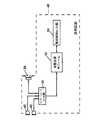
本発明はフィードバック及びフィード・フォワードの騒音減少システムのどちらにも適用可能であるが、ここでは、如何なる信号処理も伴わないような、図1に図示される最も基本的な形態のフィード・フォワードの場合について述べる。図1に示される構成では、イヤーフォン或いはヘッドフォンの聴解デバイス(図中、「e/hフォン」)10を聴解している個人の周囲に発生する周囲音響騒音は、e/hフォン10のハウジング14上の或いは内蔵の少なくとも1つのマイクロフォン12により検知される。この信号は、増幅及び反転回路16において、電気的に反転され、加算回路18により、所望のe/hフォン駆動信号(例えば、ライン20に入力し、バッファ増幅器22を介して加算回路18に供給される音楽或いは音声信号)に加算される。 The present invention is applicable to both feedback and feed forward noise reduction systems, but here the most basic form of feed forward illustrated in FIG. 1 such that no signal processing is involved. Describe the case. In the configuration shown in FIG. 1, ambient acoustic noise generated around an individual listening to an earphone or headphone listening device ("e / h phone" in the figure) 10 is the
これが、線4及び駆動増幅器26を通じて、e/hフォン10の拡声器28に与えられる信号を生成する。拡声器28に与えられる駆動信号はこうして線20上に受信する所望の駆動成分だけでなく、騒音減少成分をも含み、騒音減少成分は、理想的には、拡声器28による音響信号中に一旦反転され、直に入って来る周囲音響騒音信号に対して、振幅が等しく、しかしながら、極性が反対であり、周囲音響騒音はe/hフォン・シェル14と外耳30との間の空洞内のe/hフォン拡声器出力ポートに隣接する。結果として、弱め合う波干渉が、入って来る音響騒音とその反転との間で生じ、e/10の拡声器28を通じて生成され、聴解者により知覚される周囲音響騒音レベルは減少される。 This produces the signal applied to the
効果的フィード・フォワード周囲雑音減少においては、生成された音響的減少信号の周波数依存振幅及び位相特性は、聴解者の鼓膜における入って来る周囲雑音信号の周蓮依存振幅及び位相特性にぴったりと一致していなければならない。驚異的にぴったり一致した許容誤差がたとえ比較的に控えめな騒音減少量についても必要であることが知られている。例えば、65%(−9dB)の減少を達成するには、完全に位相が一致するとして、生成された音響減少信号は、入って来る周囲雑音信号にプラス・マイナス3dBの範囲内で一致しなければならない。同様に、振幅が完全に一致したとしても、信号間の相対的位相はプラス・マイナス20°(0.35ラジアン)の範囲内の状態でなければならない。 In effective feed-forward ambient noise reduction, the frequency-dependent amplitude and phase characteristics of the generated acoustically reduced signal closely match those of the incoming ambient noise signal at the eardrum of the listener. It must be done. It is known that a surprisingly close tolerance is necessary even for relatively modest noise reductions. For example, to achieve a 65% (-9 dB) reduction, the generated acoustic reduction signal must match the incoming ambient noise signal within plus or minus 3 dB, as fully in phase. You must. Similarly, even if the amplitudes are perfectly matched, the relative phase between the signals must be within plus or minus 20 ° (0.35 radians).
しかしながら、外付け周囲雑音信号は、鼓膜に直接入って来る騒音信号とコンポーネント12、16、18、26、及び、28により与えられる合成騒音減少相応信号との両方を共通したソースとするが、これらの両方の信号は鼓膜への夫々の音響的及び電気的経路により非常に異った態様で変更される。これらの相違が過度でないなら、電子的信号処理を導入し、相違を補償し、(合成された)減少信号の振幅及び位相の特性を、入って来る周囲雑音信号の振幅及び位相の特性に十分に合わせるように再調整することが出来る。この信号処理は、図2及び3に示されるように、1つ或いは複数のマイクロフォン12からe/hフォン拡声器28への経路内の直列処理部32として好都合に導入され、ここで図1に共通する部分については同一の参照番号を付している。 However, the external ambient noise signal is a common source of both the noise signal coming directly into the tympanic membrane and the synthetic noise reduction commensurate signal provided by the
種々の基本的な信号経路が図2に物質的に図示され、図3にブロック図形式で図示されている。各信号経路は、周波数依存振幅特性及び関連する周波数依存位相特性を有する伝達関数を夫々有している。4つのこれら基本的伝達関数は以下のようである。 Various basic signal paths are materially illustrated in FIG. 2 and in block diagram form in FIG. Each signal path has a transfer function with a frequency dependent amplitude characteristic and an associated frequency dependent phase characteristic, respectively. The four basic transfer functions are as follows.
1.周囲から耳(Ambient−to−Ear:AE)
これは耳に到達する外付け周囲雑音信号による音響的漏れ経路を表し、イヤーパッド及びe/hフォン・ケース14の周囲及びイヤーパッド及びe/hフォン・ケース14を通じての伝達を含む。1. Ear from the surroundings (Ambient-to-Ear: AE)
This represents the acoustic leakage path due to the external ambient noise signal reaching the ear, including the transmission around the ear pad and e /
2.周囲からマイクロフォン(Ambient−to−Microphone(s):AM)これは動作モードに配置されている外付けマイクロフォン(或いは複数のマイクロフォン)12の音響電気的応答を表し、局在的音響効果の局在的な(例えば、聴解者のヘッドの)音響効果を含む。2. Ambient-to-Microphone (s) (AM) This represents the acousto-electrical response of the external microphone (or microphones) 12 placed in the operating mode, localizing the localized acoustic effects Sound effects (eg, of the listener's head).
3.駆動部から耳(Driver−to−Ear:DE)
これはe/hフォンの駆動部(小型で高い適用性の拡声器28)と聴解者の鼓膜との間の電気音響的結合を表す。これは駆動部が駆動する音響的負荷によって強く影響され、その重要な特性は、駆動部から耳空と外側周囲との間の音響的漏れ経路(上記項目1)である。3. Driver's ear (Driver-to-Ear: DE)
This represents the electroacoustic coupling between the drive of the e / h phone (small and highly applicable loudspeaker 28) and the eardrum of the listener. This is strongly influenced by the acoustic load driven by the drive, an important property of which is the acoustic leakage path between the ear and the outer periphery from the drive (
4.電子的増幅(Electronic Amplification:A)
これは増幅器16の電気的伝達関数である。周波数の関数として「平坦」(即ち、相対的に一定)の増幅特性を示すことはごく普通であるが、1つ或いは複数のAC結合部を取入れることは通常は必要であり或いは現実的には都合がよく、これらは限定的ローカット(ハイパス)として振舞う。この点を考慮することが重要である。4. Electronic amplification (A)
This is the electrical transfer function of the
これらの伝達関数についての知得から、所望の引出すべき信号処理伝達関数が得られる。特に、信号処理伝達関数は、周囲からマイクロフォン(複数のマイクロフォン)、増幅器の伝達関数、信号処理伝達関数、及び、駆動部から耳の伝達関数の積が周囲から耳の伝達関数の反転と等しくなるようでなければならない。 From knowledge of these transfer functions, the desired signal processing transfer functions to be derived can be obtained. In particular, the signal processing transfer function is such that the product of the microphone (multiple microphones), the amplifier transfer function, the signal processing transfer function, and the driver to ear transfer function from the surroundings is equal to the inversion of the surroundings to ear transfer function It must be like.
図2はイヤーフォンを通じて聴解者の耳に達する音響を示すが、同様の原理が携帯電話送受話器、或いは、携帯無線機、或いは、その他の同様の機器を通じてユーザが聴解する場合にも適用されることは明らかである。 Figure 2 shows the sound that reaches the listener's ear through the earphone, but the same principle applies to the case where the user listens through a cell phone handset or a portable radio or other similar device Is clear.
しかしながら、既に述べたことから分るであろうことは、上記の如く決められる伝達関数、また、従って、伝達関数が求める信号処理は、一方において、ユーザが組込み型拡声器或いは携帯電話送受話器を直接聴解する状況下と、他方において、ユーザがe/hフォンを通じて聴解する状況下と、の間では大きな相違がある。本発明は、充分に成功した騒音減少のために必要な厳格に合致する許容度の認識に基づき、この問題点に取組む。 However, it will be appreciated from what has already been stated that the transfer function determined as described above, and thus also the signal processing sought by the transfer function, on the one hand, the user uses an embedded loudspeaker or a cell phone handset. There is a significant difference between directly listening situations and, on the other hand, situations where the user is listening through an e / h phone. The present invention addresses this problem based on the recognition of the strictly matching tolerances necessary for a sufficiently successful noise reduction.
導き出される信号処理特性は、異なる夫々のe/hフォンのタイプの特定の音響的及び電気的特質の極めて依存し、各特定のe/hフォン・システムに特有である。異なるe/hフォンは、このように、理想的には、異なる信号処理パラメータが必要であり、本発明の或る実施例はこの問題点にも又取組んでいる。 The derived signal processing characteristics are highly dependent on the specific acoustic and electrical characteristics of the different respective e / h phone types and are specific to each specific e / h phone system. Different e / h phones thus, ideally, require different signal processing parameters, and certain embodiments of the present invention also address this issue.
本発明はこのように、ここで述べられる一実施例において、携帯電話送受話器のような装置のための騒音減少回路を提供し、騒音減少回路は「内蔵」モードと「外付け」モードのような全く異なった2つの動作モードの間を自動切替えるための手段を有し、そして、騒音減少回路は、変換手段を通じて、送受話器の内部に備えられ、或いは、(e/hフォンを使用するときのように)送受話器の外部に設けられ、いずれにあっても、必要な騒音減少信号処理を伴っている。この騒音減少回路は送受話器の中央処理装置(CPU)自体、或いは、好ましくは、別個の専用集積回路(ディジタル或いはアナログ)或いは個別アナログ回路として提供される。 The present invention thus provides, in one embodiment described herein, a noise reduction circuit for a device such as a mobile phone handset, the noise reduction circuit such as "built-in" mode and "externally" mode And means for automatically switching between two completely different operation modes, and the noise reduction circuit is provided inside the handset through the conversion means, or when using (e / h phone And so on) outside the handset, and in any case, with the necessary noise reduction signal processing. The noise reduction circuit may be provided as the central processing unit (CPU) of the handset itself, or preferably as a separate dedicated integrated circuit (digital or analog) or a separate analog circuit.
既に述べられたように、複数マイクロフォン及び単数信号処理技術における昨今の改良は、今や、周囲雑音減少機能が携帯電話送受話器内に取り込まれることを可能にし、そうして、聴解者の耳元での周囲雑音減少が達成される。この例は例えば本出願人の前述の英国特許出願番号GB2436657に開示され、その図14は3つのマイクロフォン列を有する送受話器を示している。以下では、2つのマイクロフォンを持つ送受話器が(単なる例示目的として)、図4から7を参照して述べられる。 As already mentioned, recent improvements in multi-microphone and single-signal processing techniques now allow ambient noise reduction functions to be incorporated into a mobile phone handset, and so on at the listener's ear Ambient noise reduction is achieved. This example is disclosed, for example, in the applicant's above-mentioned British patent application no. GB2436657, whose figure 14 shows a handset with three microphone rows. In the following, a handset with two microphones (for the purpose of illustration only) will be described with reference to FIGS.
この例では、マイクロフォン40及び42(図5から図7参照)は、送受話器内に内蔵的に搭載され、夫々の受入ポートにより周囲環境と交信し、受入ポートの1つは図4中に41として示され、他のマイクロフォンの受入ポートの場所は矢印43で示されている。このように、受入ポートは送受話器46の「跳ね上げ」部44の反対側に対称的に配置されている。 In this example, the
表示スクリーン45が送受話器46の「跳ね上げ」部44上に設けられている。 A
図4はマイクロフォンの受入ポート41、43についての取り得る配置の一例を示しているが、必要なら、受入ポートについての別の取付け配置が成されてもよく、とは言え、必要なら、マイクロフォン40及び42のより活動的な表面が送受話器の表面に直接露出されてもよい。 Although FIG. 4 shows an example of a possible arrangement for the
如何なる場合も、マイクロフォン40及び42の据付位置、及び、又は、どの受入ポート、及び、又は、マイクロフォンに受入ポートを連結する伝達経路の据付位置及び構成は、ユーザの音声よりも周囲雑音に選択的に敏感であることが望ましい。 In any case, the mounting position of the
2つのマイクロフォン40及び42はこうして聴解者の耳に入って来る周囲雑音を表す信号を発生するように構成されている。その信号から、騒音減少信号が生成され、ユーザの耳の近くに置かれる、マイクロスピーカーの取出ポート48から伝達され、こうして、所定程度の活動的な騒音減少が与えられる。 The two
この構成は図5にブロック図形式で示されており、送受話器46の「跳ね上げ」部44上の2つのマイクロフォン40及び42からの信号はインターフェース「A」モジュール50内に流れ込み、インターフェース「A」モジュール50は、必要なマイクロフォン・バイアス用ソース及びローレベルのマイクロフォン信号を増幅して後続の信号処理段階に適するようにするためのバッファ予備増幅器を有している。インターフェース「A」モジュール50はまた、使用中には、ユーザの耳の近くに勿論置かれる取出しポート48に隣接する送受話器マイクロスピーカー28(時として「受話器」と呼ばれる。)を駆動するに適した駆動増幅器を含んでいる。 This configuration is shown in block diagram form in FIG. 5 in which the signals from the two
使用中において、マイクロフォン40及び42からの信号はインターフェース「A」モジュール50を通じて音響処理モジュール52に流入し、音響処理モジュール52は、コントローラ54の影響下で、ハイ及びローパス・フィルター、バンドパス・フィルター、レベル制御等の種々の信号処理を実行する。音響処理モジュール52及びコントローラ54は送受話器44内で統合化され、送受話器の中央処理装置(CPU)内に提供出来、或いは、例えば、別個の専用集積回路(ディジタル或いはアナログ)として、或いは、個別アナログ回路として提供されてもよい。適切な処理の後、騒音減少信号が「A」インターフェースを通じて内蔵拡声器28に与えられ、それにより、ユーザの耳元で音響的騒音減少信号が発生する。この動作のモードを便宜上「内蔵」動作モードと呼ぶことが出来る。 In use, the signals from the
携帯電話送受話器は、上述のように,しばしば、耳内フォン(所謂「イヤーバズ型イヤーフォン」)のようなe/hフォンと伴に用いられ、それらが用いられるのは、プライバシー或いはより良い信号対騒音比の何れかのためであり、或いは、「ハンズフリー」構成のためであり、そして、既に説明したように、本発明の目的はこのような場合に対してもまた周囲雑音減少を提供することである。内蔵型騒音減少イヤーバズ型イヤーフォンを設けることは可能であるが、これらはそれ自体のバッテリー供給及び電子手回路を必要とし、そのため、ユーザには更なる支出を招き、より嵩張り、より重くなり、使用時の利便は低くなる。従って、騒音減少信号処理部が送受話器内に組込まれ、送受話器の電源を利用することが便利である。これは嵩張らず廉価でユーザにとって非常に便利で、イヤーバズの夫々は適切な接続手段により統合したマイクロフォンに繋がることだけが要求される。 Mobile phone handsets are often used with e / h phones such as in-ear phones (so-called "earbuzz-type earphones") as described above, and they are used for privacy or better signal pairing For any of the noise ratios, or for a "hands free" configuration, and as already explained, the object of the invention also provides ambient noise reduction for such cases It is. While it is possible to provide built-in noise reduction earbuds earphones, these require their own battery supply and electronic hand circuitry, which causes the user to spend more, becoming more bulky and heavier, Convenience at the time of use becomes low. Therefore, it is convenient to incorporate the noise reduction signal processing unit into the handset and to use the handset power supply. This is bulky, inexpensive and very convenient for the user, and each of the earbads need only be connected to the integrated microphone by means of appropriate connection means.
しかしながら、信号処理特性は決定的にイヤーバズ(或いは、他のe/hフォン)の音響特性、及び非常に大きくこれらのパラメータに依存する。異なる信号処理構成が、内蔵モード(図5)について、及び、イヤーバズ(或いは、他のe/hフォン)使用(外付けモード)について、求められる。実際に、異なるタイプのイヤーバズ(或いは、他のe/hフォン)は、内蔵容積、駆動装置、及び音響的漏れにおいて異なることから、異なる音響特性を有しており、異なるフィルター特性を表すような、異なる電子的信号処理構成を必要とする。 However, the signal processing characteristics depend decisively on the acoustics of the earbuzz (or other e / h phones) and very largely on these parameters. Different signal processing configurations are required for built-in mode (FIG. 5) and for earbuzz (or other e / h phone) usage (external mode). In fact, different types of earbuzz (or other e / h phones) have different acoustic characteristics due to differences in built-in volume, drive and acoustical leakage, such as exhibiting different filter characteristics , Require different electronic signal processing configurations.
本発明のこの例は、携帯電話送受話器の形態の通信装置を提供し、外付けイヤーバズの使用を検知し、騒音減少構成をイヤーバズが使用されている外付けモードにも、イヤーバズが使用されていない(即ち、プラグ接続されていない)内蔵モードにも、切替えるための自動切替え手段を含んでいる。本発明のこの実施例はまた、種々の異なるタイプの外付けイヤーバズを検知し、識別し、そして、ある範囲内のイヤーバズのタイプに関連する予め記憶されたフィルター特性に従って信号処理を適切な構成に自動的に切替える。こうして、特定の製造元の送受話器は、別の製造元により製造されたものを含む、ある範囲内のイヤーバズとともに用いられ、そして、ユーザは唯1つのイヤーバズに限定されない。 This example of the present invention provides a communication device in the form of a cell phone handset, detects the use of an external ear buzz, and uses an ear buzz in an external mode where the noise reduction configuration is used. The non-embedded (ie not plugged in) built-in mode also includes automatic switching means for switching. This embodiment of the present invention also detects and identifies various different types of external ear buzz, and properly configures the signal processing according to pre-stored filter characteristics associated with the range of ear buzz types. Switch automatically. Thus, a particular manufacturer's handset is used with a range of ear buzz, including those manufactured by another manufacturer, and the user is not limited to only one ear buzz.
図6はそのような切替え構成の簡略化したブロック図を示し、明確化のため、全ての個々の電気的接続を示すのではなく、個々の信号経路を示し、例えば、マイクロフォン及び拡声器の接続は電気的な1つの対ではなく1本の信号経路として示されている。送受話器46に取り込まれたマイクロフォン40及び42及び拡声器28は依然として「A」インターフェースを介して接続されている(内蔵モード)。加えて、今度は、外付け用レセプター60が設けられ、外付け用レセプター60には、コネクター検知手段76が取付けられ、この例ではイヤーバズ62、63を含む外付けe/hフォンがプラグ接続され、イヤーバズ62、63は夫々、マイクロスピーカー64、65、及び周囲雑音を検出するためのマイクロフォン66、67を有している。外付け用レセプター60はインターフェース「B」モジュール70に接続され、インターフェース「B」モジュール70は、必要なマイクロフォン・バイアス用ソース及びマイクロフォン66及び67からの低レベル信号を増幅して後続の信号処理段階に適するようにするためのバッファ予備増幅器を有している。インターフェース「B」モジュール70はまたイヤーバズ・マイクロスピーカー64及び65を駆動するに適した2チャンネル駆動増幅器を含んでいる。 FIG. 6 shows a simplified block diagram of such a switching arrangement, and for the sake of clarity, shows not individual individual electrical connections but individual signal paths, for example microphone and loudspeaker connections. Is shown as a single signal path rather than a single electrical pair. The
インターフェース「A」50及び「B」70は共にバス選択スイッチ72を介して音響処理モジュール52に接続され、バス選択スイッチ72が、外付け用コネクター検知手段76に接続された制御手段74の判断により、内蔵或いは外付けの何れのトランスデューサからの信号を受取り、或いは、何れのトランスデューサへと信号を送出し、イヤーバズがレセプター60に挿入されているときは、インターフェース「B」70が選択され(外付けモード)、何もレセプター60に挿入されていないときは、システムは切替えてインターフェース「A」モジュール50を選択する(内蔵モード)。モジュール52により実行される処理は、ソフトウェア・スイッチング・システム58に応じて、制御手段74に従って、内蔵処理コントローラ54或いは外付けコントローラ56により判断され、更には、制御手段74の切替えは、外付け用コネクター60が62、63のようなe/hフォンへの接続を支持するように用いられているか否かにより判断される。異なる騒音減少処理が、送受話器46の内蔵スピーカー28を用いるか、或いは、その代わりに、外付けe/hフォンを用いるかどうかによって、自動的に実行されることがこうして理解できる。 The interfaces "A" 50 and "B" 70 are both connected to the
プラグ検知手段76は種々の方法で実現できるが、1つの好都合な技法は、レセプター60内にコネクタ・ピンを用意することを含み、それは送受話器の多経路ソケットとして好都合に構成されてもよく、コネクタ・ピンは「プルアップ」抵抗に接続されており(即ち、電流制限抵抗を通じて電源供給源にバイアスされており)、そして、レセプター60の多経路ソケットへの挿入に適した多経路プラグ・コネクタ中の対応導線は電気的に接地される構成であり、そうして、プラグが多経路ソケットに挿入されているときには導線ピン上の電圧がその初期設定の「高」値(電源供給電圧)ではなく「低」(ゼロV)になる。この電圧変化は、そしてコントローラ・モジュールにより検知され、コントローラ・モジュールは、(a)音響処理モジュールへの接続についての適切なインターフェース(内蔵或いは外付け)を選択し、そして、(b)適切な信号処理方式を選択する。後者は、デジタル信号処理手段が提供されるところのソフトウェア・スイッチにより、或いは、アナログ信号処理方式が用いられるとろのハードウェア・スイッチにより、実行されてよい。 While the plug detection means 76 can be implemented in a variety of ways, one convenient technique involves providing connector pins in the
図6は、インターフェース「A」50、インターフェース「B」70、音響処理モジュール52、内蔵処理コントローラ54、外付け処理コントローラ56、ソフトウェア・スイッチング・システム58、バス選択スイッチ72、及び、制御手段74を別々のコンポーネントとして有する騒音減少回路を示している。しかしながら、これらのコンポーネントの幾つか或いは全てが都合良く単一の集積回路内に提供されてもよい。例えば、騒音減少回路が、マイクロフォン40、42への接続のための第1入力、及び、スピーカー28への接続のための対応出力、及び、マイクロフォン66、67への接続のための第2入力、及び、スピーカー64、65への接続のための対応出力を備えた1つの集積回路の形で提供され得る。この集積回路は例えばソケット検知ブロック76からの入力を受取り、マイクロフォンが第2入力に接続されているか否かを判断する。 6 shows interface “A” 50, interface “B” 70,
この場合、騒音減少回路は、マイクロフォンが第2入力に接続されていないと判断されると第1伝送関数を第1入力から受信した信号に適用して騒音打消し信号を生成し、第2入力に第2マイクロフォンが接続されていると判断されると第2伝達関数を第2入力に接続されたマイクロフォンから受信した信号に適用して騒音打消し信号を生成するように適合されている。第2伝達関数は第1伝達関数とは相違している。 In this case, the noise reduction circuit applies the first transmission function to the signal received from the first input to generate a noise cancellation signal when it is determined that the microphone is not connected to the second input, and the second input is generated The second transfer function is adapted to be applied to the signal received from the microphone connected to the second input to generate a noise cancellation signal when it is determined that the second microphone is connected to the second microphone. The second transfer function is different from the first transfer function.
上述のように、種々の異なるイヤーバズ或いはその他のe/hフォンを適切に処理する選択肢が提供されることがまた有利である(但し、必須ではない)。e/hフォンの異なるタイプの所定範囲内の信号処理特性が送受話器内に予め決められたパラメータとして記憶され、使用中のe/hフォンの実際のタイプが機械的、及び、又は、電子的に識別されて適切な信号処理パラメータが選択され得る。 As mentioned above, it is also advantageous (but not essential) that an option is provided to handle various different earbuds or other e / h phones properly. Signal processing characteristics within a predetermined range of different types of e / h phones are stored as predetermined parameters in the handset, the actual type of e / h phones in use being mechanical and / or electronic And appropriate signal processing parameters may be selected.
そのような識別手順が図7に示され、図7は一対の騒音減少イヤーバズ62、63を図示し、騒音減少イヤーバズ62、63はマイクロスピーカー64、65の各々、及び、マイクロフォン66、67の各々を備え、一対の騒音減少イヤーバズ62、63は送受話器46のコネクターを有する多経路ソケットにプラグ接続されるように示されている。識別は、この例では、幾つかの専用導線がデジタル・バイナリー・コード・バイトとしての役割を果たすことにより達成され、個々の導電線はコード番号に従ってグランドに接続され、上述の配列と同様に、「プルアップ」検知配列で用いられる。 Such an identification procedure is illustrated in FIG. 7, which illustrates a pair of noise
例えば、コネクター60のピン3、4、及び5は図7の配列中のこの機能を果たし、ピン3は3ビット・バイナリー・ワードの最上位ビット(MSB)を表し、ピン5は最下位ビット(LSB)を表している。ピン4及び5は接地され、こうして、10進法の数4に対応し、従って、このプラグがコネクター60に挿入されると、制御手段は外付けモード及びイヤーバズ・タイプ(8のうちの)4のための信号処理方式をも選択する。初期設定されたイヤーバズ処理方式は送受話器とともに提供されるイヤーバズの処理方式に初期設定されるが、ユーザにより別の選択肢に再設定され得る。 For example, pins 3, 4 and 5 of
この図示の実施例では、識別の仕組みは、イヤーバズが携帯電話送受話器上に設けられた識別デバイスによって識別される。しかしながら、同じ仕組みが、接続されるべき如何なる装置(例えば、ポータブル音楽プレイヤー)によるイヤーバズ、或いは、他の聴解デバイスの識別に用いられ得る。 In this illustrated embodiment, the identification scheme is identified by an identification device in which the ear buzz is provided on the mobile handset. However, the same mechanism can be used to identify ear buzz or other listening devices by any device (eg, portable music player) to be connected.
識別の仕組みは、特定のモデルとして聴解デバイスを識別してもよいし、或いは、聴解デバイスをより低い詳細さで識別してよく、例えば、特定の騒音減少伝達関数を必要とする特定の特性を有する聴解デバイスのグループの一員として識別してもよい。 The identification scheme may identify the hearing device as a particular model, or may identify the hearing device with less detail, eg, particular characteristics that require a particular noise reduction transfer function. It may be identified as a member of the group of listening devices it has.
代替例として、信号処理方式はユーザ選択可能であってもよいし、ユーザ調節可能であってもよい。この場合、ユーザ・インターフェースは表示スクリーン45により提供されてもよく、キー手段により或いはタッチ・スクリーンを通じて或いは他のどのような便利な方法でもよく、ユーザが所望の入力を選択できるものであってもよい。 Alternatively, the signal processing scheme may be user selectable or user adjustable. In this case, the user interface may be provided by the
こうして、ヘッドフォン、イヤーフォン、或いは、イヤーバズ等の聴解デバイスであって、プラグ及びソケットの組み合わせの手段により、或いは、ブルートゥース或いは別のプロトコルの近接範囲の無線接続を通じて接続された聴解デバイスの使用時、ユーザは適切な騒音減少伝達関数を選択できる。ユーザはまた、送受話器装置自体のマイクロフォン(単数又は複数)及びスピーカー(単数又は複数)の使用に適した騒音減少伝達関数から異なっている騒音減少伝達関数を選択してもよい。代替的に、ユーザは、各々が聴解デバイスの特定のモデルやクラスの使用に適した複数の騒音減少伝達関数から選択可能であってもよい。 Thus, when using a listening device such as a headphone, ear phone or ear buzz, by means of a combination of plug and socket or connected via a close range wireless connection of Bluetooth or another protocol, the user Can select an appropriate noise reduction transfer function. The user may also select a noise reduction transfer function that is different from the noise reduction transfer function suitable for use with the microphone device (s) and the speaker (s) of the handset device. Alternatively, the user may be able to select from multiple noise reduction transfer functions, each suitable for use with a particular model or class of listening device.
ユーザにとっての付加的機能強化が、既に開示されたように、電車中や飛行機中のような、異なる周囲雑音状況中での使用について、ユーザ選択可能な騒音減少伝達の使用を含む、切替え方式と関連させて使用できる。更には、周囲雑音減少効果は、GB2436657に記述されているように、(閾値を超えた)過剰な周囲雑音、音楽録音再生の検知、及びまた聴解者の頭部の物理的な動き、等の種々の外部刺激に従って上下されてもよい。携帯電話使用での価値ある機能強化は、入って来る電話呼び出しをきっかけとする騒音減少のレベル管理と関連し、もし周囲雑音減少に切替えられているイヤーバズを通じて音楽再生している最中に入って来る呼び出しが起きると、それが騒音減少の低下となり、そうして、ユーザは外界の気付きが大きくなり、用心深い働きに貢献する。 A switching scheme, wherein additional enhancements for the user include the use of user selectable noise reduction transmissions for use in different ambient noise situations, such as in trains and planes, as already disclosed. It can be used in connection. Furthermore, the ambient noise reduction effect is, as described in GB2436657, excessive ambient noise (above threshold), detection of music recording and reproduction, and also physical movement of the listener's head, etc. It may be raised and lowered according to various external stimuli. Valuable enhancements in mobile phone use are associated with level control of noise reduction triggered by incoming telephone calls, and if during music playback through the earbuzz switched to ambient noise reduction. When an incoming call occurs, that reduces the noise reduction, and so the user becomes more aware of the outside world and contributes to a cautious work.
更に、騒音減少伝達関数はユーザにより調整されてもよい。例えば、携帯電話送受話器のような装置内のマイクロフォン及びスピーカーのようなコンポーネントは相対的に大きな許容度があり、そして、このように最適な騒音減少伝達関数はある装置から別の装置に亘って極めて著しく変化し得る。その様な装置にとって最良の可能な騒音減少の遂行を提供するには、上述のユーザ・インターフェースはユーザが騒音減少伝達関数を選択或いは調整できるものであってもよい。 Furthermore, the noise reduction transfer function may be adjusted by the user. For example, components such as microphones and speakers in devices such as cellular telephone handsets have relatively large tolerances, and thus the optimal noise reduction transfer function can be from one device to another It can change quite significantly. To provide the best possible noise reduction performance for such devices, the user interface described above may allow the user to select or adjust the noise reduction transfer function.
上述の各実施例は発明を限定するものではなく、当業者は添付の特許請求の範囲から逸脱することなく種々の代替的実施例を作ることが出来る。「有する」という用語は、特許請求の範囲内に列挙された要素やステップの以外の存在を排除せず、「1つの」或いは「単数の」は複数を排除せず、1つの特徴或いは他のユニットは特許請求の範囲内に記述された幾つかのユニットの機能を充当する。特許請求の範囲内のいかなる参照番号も特許請求の範囲を限定すると解すべきではない。 The embodiments described above do not limit the invention, and one of ordinary skill in the art can make various alternative embodiments without departing from the scope of the appended claims. The word "comprising" does not exclude the presence of elements or steps other than those listed in a claim, and "a" or "singular" does not exclude a plurality, and does not exclude one or more features. The units fulfill the functions of several units described in the claims. Any reference numerals in the claims should not be construed as limiting the claims.
10 聴解デバイス(e/hフォン)
12 内蔵マイクロフォン
28 拡声器(スピーカー)
30 耳(外耳)
40、42 マイクロフォン
41、43 受入ポート
44 跳ね上げ部
45 表示スクリーン
46 送受話器
48 取出ポート
50、70 インターフェース
52 音響処理モジュール
54 内蔵処理コントローラ
56 外付けコントローラ
60 外付け用レセプター
62、63 イヤーバズ
64、65 マイクロスピーカー
66、67 マイクロフォン
72 バス選択スイッチ
74 制御手段
76 コネクター検知手段10 Listening device (e / h phone)
12 built-in
30 ears (outer ear)
40, 42
Claims (22)
Translated fromJapanese少なくとも1つの第1マイクロフォンからの信号を受信するための第1入力、
少なくとも1つの第2マイクロフォンからの信号を受信するための第2入力、及び、
第2マイクロフォンが第2入力に接続されているかどうかを判断するための手段、
を備えており、
騒音減少回路は、
第2マイクロフォンが第2入力に接続されていないと判断されときに第1マイクロフォンから受信した信号に第1伝達関数を適用することにより騒音打消し信号を生成するように適合され、そして、
第2マイクロフォンが第2入力に接続されていると判断されときに第2マイクロフォンから受信した信号に第2伝達関数を適用することにより騒音打消し信号を生成するように適合され、
第2伝達関数は第1伝達関数とは相違している、
騒音減少回路。Noise reduction circuit,
A first input for receiving a signal from at least one first microphone;
A second input for receiving a signal from at least one second microphone;
Means for determining if the second microphone is connected to the second input,
Equipped with
The noise reduction circuit is
Adapted to generate a noise cancellation signal by applying a first transfer function to the signal received from the first microphone when it is determined that the second microphone is not connected to the second input, and
Adapted to generate a noise cancellation signal by applying a second transfer function to the signal received from the second microphone when it is determined that the second microphone is connected to the second input,
The second transfer function is different from the first transfer function,
Noise reduction circuit.
通信機器の周囲の周囲雑音を検知するための少なくとも1つの内蔵マイクロフォン、
通信機器のユーザにより聴かれる音響信号を生成するための内蔵スピーカー、
聴解デバイス・スピーカー及び聴解デバイス・マイクロフォンを備え、周りの周囲雑音を検知するための聴解デバイスを受入れるための手段、
聴解デバイスが通信機器に接続されているかどうかを判断するための手段、及び、
騒音減少回路、
を備え、
騒音減少回路は、
内蔵スピーカーからの信号を受信するための第1入力、
聴解デバイス・マイクロフォンからの信号を受信するための第2入力、及び、
聴解デバイスが通信機器に接続されているかどうかを判断するための手段からの信号を受信するための手段、
を備え、
騒音減少回路は、
聴解デバイスが通信機器に接続されていないと判断されると、内蔵スピーカーから受信した信号に第1伝達関数を適用して騒音打消し信号を生成し、騒音打消し信号を内蔵スピーカーに適用するように適合され、
聴解デバイスが通信機器に接続されていると判断されると、聴解デバイス・マイクロフォンから受信した信号に第2伝達関数を適用して騒音打消し信号を生成し、騒音打消し信号を聴解デバイス・スピーカーに適用するように適合され、
第2伝達関数は第1伝達関数とは相違している、
通信機器。A communication device,
At least one built-in microphone for detecting ambient noise around the communication device,
Built-in speakers for generating audio signals to be heard by the user of the communication device,
Means for receiving a listening device for detecting ambient noise in the surroundings, comprising a listening device speaker and a listening device microphone,
Means for determining whether a listening device is connected to the communication device;
Noise reduction circuit,
Equipped with
The noise reduction circuit is
1st input for receiving signal from built-in speaker,
A second input for receiving a signal from the listening device microphone;
Means for receiving a signal from the means for determining whether the listening device is connected to the communication device;
Equipped with
The noise reduction circuit is
If it is determined that the listening device is not connected to the communication device, the first transfer function is applied to the signal received from the built-in speaker to generate a noise cancellation signal, and the noise cancellation signal is applied to the built-in speaker Is adapted to
When it is determined that the listening device is connected to the communication device, a second transfer function is applied to the signal received from the listening device microphone to generate a noise cancellation signal, and the noise cancellation signal is the listening device speaker Adapted to apply to
The second transfer function is different from the first transfer function,
Communication equipment.
騒音減少回路は第2伝達関数を聴解デバイス・マイクロフォンから受信した信号に適用して騒音打消し信号を生成するように適合され、
第伝達関数は、識別手段により通信機に接続中であると特定されている間は聴解デバイスのタイプに依存している、
請求項5乃至8の1つの通信機器。The means for determining whether the listening device is connected to the communication device comprises means for distinguishing between at least two different types of listening devices connectable to the handset,
The noise reduction circuit is adapted to apply the second transfer function to the signal received from the listening device microphone to generate a noise cancellation signal,
The first transfer function depends on the type of listening device while being identified as being connected to the communicator by the identification means.
A communication device according to one of claims 5 to 8.
Applications Claiming Priority (2)
| Application Number | Priority Date | Filing Date | Title |
|---|---|---|---|
| GB0708860.2AGB2449083B (en) | 2007-05-09 | 2007-05-09 | Cellular phone handset with ambient noise reduction |
| PCT/GB2008/001601WO2008139155A1 (en) | 2007-05-09 | 2008-05-08 | Communication apparatus with ambient noise reduction |
Publications (1)
| Publication Number | Publication Date |
|---|---|
| JP2010527541Atrue JP2010527541A (en) | 2010-08-12 |
Family
ID=38198909
Family Applications (1)
| Application Number | Title | Priority Date | Filing Date |
|---|---|---|---|
| JP2010506997APendingJP2010527541A (en) | 2007-05-09 | 2008-02-08 | Communication device with ambient noise reduction function |
Country Status (7)
| Country | Link |
|---|---|
| US (6) | US8953814B2 (en) |
| EP (3) | EP2153435B1 (en) |
| JP (1) | JP2010527541A (en) |
| CN (1) | CN101681617B (en) |
| GB (1) | GB2449083B (en) |
| TW (1) | TW200847739A (en) |
| WO (1) | WO2008139155A1 (en) |
Cited By (1)
| Publication number | Priority date | Publication date | Assignee | Title |
|---|---|---|---|---|
| JP2014060525A (en)* | 2012-09-14 | 2014-04-03 | Rohm Co Ltd | Wind noise reduction circuit, wind noise reduction method and audio-signal processing circuit using the same, and electronic apparatus |
Families Citing this family (23)
| Publication number | Priority date | Publication date | Assignee | Title |
|---|---|---|---|---|
| US20090170550A1 (en)* | 2007-12-31 | 2009-07-02 | Foley Denis J | Method and Apparatus for Portable Phone Based Noise Cancellation |
| JP4883103B2 (en) | 2009-02-06 | 2012-02-22 | ソニー株式会社 | Signal processing apparatus, signal processing method, and program |
| US8223986B2 (en) | 2009-11-19 | 2012-07-17 | Apple Inc. | Electronic device and external equipment with digital noise cancellation and digital audio path |
| DE102010004667B4 (en) | 2010-01-14 | 2016-08-11 | Austriamicrosystems Ag | Housing and speaker module |
| WO2011161487A1 (en) | 2010-06-21 | 2011-12-29 | Nokia Corporation | Apparatus, method and computer program for adjustable noise cancellation |
| US20120102629A1 (en)* | 2010-08-09 | 2012-05-03 | Spear Labs, Llc | Hearing protection system for use within a helmet |
| DE102011013343B4 (en) | 2011-03-08 | 2012-12-13 | Austriamicrosystems Ag | Active Noise Control System and Active Noise Reduction System |
| US8958571B2 (en) | 2011-06-03 | 2015-02-17 | Cirrus Logic, Inc. | MIC covering detection in personal audio devices |
| GB2510354A (en)* | 2013-01-31 | 2014-08-06 | Incus Lab Ltd | ANC-enabled earphones with ANC processing performed by host device |
| WO2015034735A1 (en)* | 2013-09-04 | 2015-03-12 | Qualcomm Incorporated | Apparatus and method for acquiring configuration data |
| CN103561174A (en)* | 2013-11-05 | 2014-02-05 | 英华达(南京)科技有限公司 | Method and system for improving SNR |
| DE102014100824A1 (en) | 2014-01-24 | 2015-07-30 | Nikolaj Hviid | Independent multifunctional headphones for sports activities |
| EP3097702A1 (en) | 2014-01-24 | 2016-11-30 | Bragi GmbH | Multifunctional headphone system for sports activities |
| KR102248071B1 (en) | 2014-09-15 | 2021-05-04 | 엘지전자 주식회사 | multimedia apparatus and method for processing audio signal thereof |
| US20160139702A1 (en)* | 2014-11-14 | 2016-05-19 | Apple Inc. | Auxiliary Sensors for Electronic Devices |
| CN104602163B (en) | 2014-12-31 | 2017-12-01 | 歌尔股份有限公司 | Active noise reduction earphone and method for noise reduction control and system applied to the earphone |
| US10238546B2 (en)* | 2015-01-22 | 2019-03-26 | Eers Global Technologies Inc. | Active hearing protection device and method therefore |
| GB201704067D0 (en)* | 2017-03-14 | 2017-04-26 | Soundchip Sa | Earphone connection apparatus |
| CN108228038B (en)* | 2017-12-22 | 2020-09-18 | 北京小米松果电子有限公司 | Noise canceling device, noise canceling method, computer-readable storage medium, and electronic apparatus |
| WO2021183136A1 (en)* | 2020-03-13 | 2021-09-16 | Hewlett-Packard Development Company, L.P. | Disabling spatial audio processing |
| US11509992B2 (en)* | 2020-11-19 | 2022-11-22 | Bose Corporation | Wearable audio device with control platform |
| EP4262231A4 (en)* | 2021-05-18 | 2024-03-13 | Shenzhen Grandsun Electronic Co., Ltd. | Noise-canceling ear pad, noise-canceling ear muff, and noise-canceling headphones |
| US12394427B2 (en)* | 2022-09-22 | 2025-08-19 | Creative Technology Ltd | Method for selective noise suppression in audio playback |
Citations (6)
| Publication number | Priority date | Publication date | Assignee | Title |
|---|---|---|---|---|
| JPH09331377A (en)* | 1996-06-12 | 1997-12-22 | Nec Corp | Noise cancellation circuit |
| JPH10294989A (en)* | 1997-04-18 | 1998-11-04 | Matsushita Electric Ind Co Ltd | Noise control headset |
| JP2001218299A (en)* | 2000-02-02 | 2001-08-10 | Nec Saitama Ltd | Melody drive system and method |
| JP2002237870A (en)* | 2001-02-09 | 2002-08-23 | Mitsubishi Electric Corp | Voice input / output device of communication device and communication device |
| JP2006229545A (en)* | 2005-02-17 | 2006-08-31 | Nec Infrontia Corp | It terminal and its audio apparatus identifying method |
| JP2006309771A (en)* | 2005-04-27 | 2006-11-09 | Lg Electronics Inc | Portable terminal having multi-function socket, communication method using multi-function socket, multi-function socket adapter and communication system using multi-function socket |
Family Cites Families (34)
| Publication number | Priority date | Publication date | Assignee | Title |
|---|---|---|---|---|
| US5138664A (en)* | 1989-03-25 | 1992-08-11 | Sony Corporation | Noise reducing device |
| FI940049A0 (en)* | 1994-01-05 | 1994-01-05 | Nokia Mobile Phones Ltd | Anordning Foer anpassning av signalnivaon i en mobil telefon |
| US5774562A (en)* | 1996-03-25 | 1998-06-30 | Nippon Telegraph And Telephone Corp. | Method and apparatus for dereverberation |
| EP0871312A1 (en)* | 1997-04-03 | 1998-10-14 | Pan Communications, Inc. | Two-way voice communication device |
| TW392416B (en)* | 1997-08-18 | 2000-06-01 | Noise Cancellation Tech | Noise cancellation system for active headsets |
| US6016136A (en)* | 1997-10-29 | 2000-01-18 | International Business Machines Corporation | Configuring audio interface for multiple combinations of microphones and speakers |
| US6549586B2 (en) | 1999-04-12 | 2003-04-15 | Telefonaktiebolaget L M Ericsson | System and method for dual microphone signal noise reduction using spectral subtraction |
| US7031460B1 (en)* | 1998-10-13 | 2006-04-18 | Lucent Technologies Inc. | Telephonic handset employing feed-forward noise cancellation |
| JP2000174897A (en)* | 1998-12-08 | 2000-06-23 | Kenwood Corp | Telephone set |
| US6859538B1 (en)* | 1999-03-17 | 2005-02-22 | Hewlett-Packard Development Company, L.P. | Plug and play compatible speakers |
| GB2360165A (en)* | 2000-03-07 | 2001-09-12 | Central Research Lab Ltd | A method of improving the audibility of sound from a loudspeaker located close to an ear |
| US20010046304A1 (en)* | 2000-04-24 | 2001-11-29 | Rast Rodger H. | System and method for selective control of acoustic isolation in headsets |
| US20020141599A1 (en)* | 2001-04-03 | 2002-10-03 | Philips Electronics North America Corp. | Active noise canceling headset and devices with selective noise suppression |
| CA2357200C (en) | 2001-09-07 | 2010-05-04 | Dspfactory Ltd. | Listening device |
| US6934396B1 (en)* | 2001-09-28 | 2005-08-23 | Gateway Inc. | Speaker embedded with oral setup tutorial |
| US20100115149A1 (en)* | 2002-12-02 | 2010-05-06 | Plantronics, Inc. | System and method for digital signaling of computer headset connection status |
| US7068797B2 (en) | 2003-05-20 | 2006-06-27 | Sony Ericsson Mobile Communications Ab | Microphone circuits having adjustable directivity patterns for reducing loudspeaker feedback and methods of operating the same |
| US20060013410A1 (en)* | 2004-04-20 | 2006-01-19 | Wurtz Michael J | Mobile-telephone adapters for automatic-noise-reduction headphones |
| US7856240B2 (en) | 2004-06-07 | 2010-12-21 | Clarity Technologies, Inc. | Distributed sound enhancement |
| US8189803B2 (en)* | 2004-06-15 | 2012-05-29 | Bose Corporation | Noise reduction headset |
| US7660605B2 (en)* | 2004-08-31 | 2010-02-09 | Research In Motion Limited | Method and system for the configuration of a mobile station baseband circuit for an acoustic accessory |
| WO2006036262A2 (en)* | 2004-09-23 | 2006-04-06 | Thomson Licensing | Method and apparatus for controlling a headphone |
| CA2581118C (en)* | 2004-10-19 | 2013-05-07 | Widex A/S | A system and method for adaptive microphone matching in a hearing aid |
| US20060135085A1 (en)* | 2004-12-22 | 2006-06-22 | Broadcom Corporation | Wireless telephone with uni-directional and omni-directional microphones |
| JP2006197075A (en) | 2005-01-12 | 2006-07-27 | Yamaha Corp | Microphone and loudspeaker |
| JP4297055B2 (en) | 2005-01-12 | 2009-07-15 | ヤマハ株式会社 | Karaoke equipment |
| US7929991B2 (en) | 2005-03-31 | 2011-04-19 | Qualcomm Incorporated | Mobile device interface for input devices |
| JP4872365B2 (en) | 2005-05-23 | 2012-02-08 | パナソニック株式会社 | Chip type solid electrolytic capacitor |
| US20080025523A1 (en)* | 2006-07-28 | 2008-01-31 | Sony Ericsson Mobile Communications Ab | System and method for noise canceling in a mobile phone headset accessory |
| JP5007561B2 (en)* | 2006-12-27 | 2012-08-22 | ソニー株式会社 | Noise reduction device, noise reduction method, noise reduction processing program, noise reduction audio output device, and noise reduction audio output method |
| EP2123114A2 (en)* | 2007-01-30 | 2009-11-25 | Phonak AG | Method and system for providing binaural hearing assistance |
| US8625812B2 (en)* | 2007-03-07 | 2014-01-07 | Personics Holdings, Inc | Acoustic dampening compensation system |
| US7877116B2 (en)* | 2007-08-31 | 2011-01-25 | Research In Motion Limited | Method and apparatus allowing for user-selectable acoustic equalizer settings for voice calls |
| US8218779B2 (en)* | 2009-06-17 | 2012-07-10 | Sony Ericsson Mobile Communications Ab | Portable communication device and a method of processing signals therein |
- 2007
- 2007-05-09GBGB0708860.2Apatent/GB2449083B/enactiveActive
- 2008
- 2008-02-08JPJP2010506997Apatent/JP2010527541A/enactivePending
- 2008-05-08EPEP08750541.8Apatent/EP2153435B1/enactiveActive
- 2008-05-08CNCN2008800200903Apatent/CN101681617B/ennot_activeExpired - Fee Related
- 2008-05-08EPEP18167352.6Apatent/EP3416162B1/enactiveActive
- 2008-05-08TWTW097116949Apatent/TW200847739A/enunknown
- 2008-05-08WOPCT/GB2008/001601patent/WO2008139155A1/enactiveApplication Filing
- 2008-05-08EPEP15203269.4Apatent/EP3026665B1/enactiveActive
- 2008-05-08USUS12/599,026patent/US8953814B2/enactiveActive
- 2015
- 2015-01-21USUS14/601,854patent/US20150139434A1/ennot_activeAbandoned
- 2019
- 2019-09-26USUS16/583,882patent/US10685636B2/enactiveActive
- 2020
- 2020-06-10USUS16/897,466patent/US10950215B2/enactiveActive
- 2020-11-17USUS16/950,318patent/US11367426B2/enactiveActive
- 2022
- 2022-05-19USUS17/748,472patent/US11741935B2/enactiveActive
Patent Citations (6)
| Publication number | Priority date | Publication date | Assignee | Title |
|---|---|---|---|---|
| JPH09331377A (en)* | 1996-06-12 | 1997-12-22 | Nec Corp | Noise cancellation circuit |
| JPH10294989A (en)* | 1997-04-18 | 1998-11-04 | Matsushita Electric Ind Co Ltd | Noise control headset |
| JP2001218299A (en)* | 2000-02-02 | 2001-08-10 | Nec Saitama Ltd | Melody drive system and method |
| JP2002237870A (en)* | 2001-02-09 | 2002-08-23 | Mitsubishi Electric Corp | Voice input / output device of communication device and communication device |
| JP2006229545A (en)* | 2005-02-17 | 2006-08-31 | Nec Infrontia Corp | It terminal and its audio apparatus identifying method |
| JP2006309771A (en)* | 2005-04-27 | 2006-11-09 | Lg Electronics Inc | Portable terminal having multi-function socket, communication method using multi-function socket, multi-function socket adapter and communication system using multi-function socket |
Cited By (1)
| Publication number | Priority date | Publication date | Assignee | Title |
|---|---|---|---|---|
| JP2014060525A (en)* | 2012-09-14 | 2014-04-03 | Rohm Co Ltd | Wind noise reduction circuit, wind noise reduction method and audio-signal processing circuit using the same, and electronic apparatus |
Also Published As
| Publication number | Publication date |
|---|---|
| US10685636B2 (en) | 2020-06-16 |
| WO2008139155A1 (en) | 2008-11-20 |
| CN101681617A (en) | 2010-03-24 |
| US11367426B2 (en) | 2022-06-21 |
| US20200027435A1 (en) | 2020-01-23 |
| US10950215B2 (en) | 2021-03-16 |
| GB2449083A (en) | 2008-11-12 |
| EP2153435A1 (en) | 2010-02-17 |
| EP3416162A1 (en) | 2018-12-19 |
| US8953814B2 (en) | 2015-02-10 |
| US20210074257A1 (en) | 2021-03-11 |
| EP3026665A1 (en) | 2016-06-01 |
| US20200302906A1 (en) | 2020-09-24 |
| TW200847739A (en) | 2008-12-01 |
| CN101681617B (en) | 2012-06-13 |
| GB2449083B (en) | 2012-04-04 |
| US11741935B2 (en) | 2023-08-29 |
| US20150139434A1 (en) | 2015-05-21 |
| EP3416162B1 (en) | 2024-07-03 |
| EP3026665B1 (en) | 2018-04-18 |
| US20220277720A1 (en) | 2022-09-01 |
| US20100086144A1 (en) | 2010-04-08 |
| GB0708860D0 (en) | 2007-06-13 |
| EP2153435B1 (en) | 2016-01-06 |
| WO2008139155A8 (en) | 2009-02-19 |
Similar Documents
| Publication | Publication Date | Title |
|---|---|---|
| US11741935B2 (en) | Communication apparatus with ambient noise reduction | |
| JP3163344U (en) | Microphone technology | |
| CN101401399B (en) | Headphones that provide ambient sound | |
| US9992591B2 (en) | Arranging an audio signal based on the number of loudspeakers | |
| EP3217686A1 (en) | System and method for enhancing performance of audio transducer based on detection of transducer status | |
| US8073153B2 (en) | System and method for engaging in conversation while using an earphone | |
| CN102972043B (en) | Headset | |
| CN104521247A (en) | Bluetooth earphone hearing aid and anti-noise method and device | |
| US20140211970A1 (en) | Earphone arrangements | |
| KR20070105555A (en) | Earphone with microphone | |
| KR101109748B1 (en) | microphone | |
| KR200346762Y1 (en) | phone system | |
| KR200295631Y1 (en) | earphone device |
Legal Events
| Date | Code | Title | Description |
|---|---|---|---|
| A621 | Written request for application examination | Free format text:JAPANESE INTERMEDIATE CODE: A621 Effective date:20110406 | |
| A977 | Report on retrieval | Free format text:JAPANESE INTERMEDIATE CODE: A971007 Effective date:20120731 | |
| A131 | Notification of reasons for refusal | Free format text:JAPANESE INTERMEDIATE CODE: A131 Effective date:20120828 | |
| A601 | Written request for extension of time | Free format text:JAPANESE INTERMEDIATE CODE: A601 Effective date:20121126 | |
| A602 | Written permission of extension of time | Free format text:JAPANESE INTERMEDIATE CODE: A602 Effective date:20121203 | |
| A02 | Decision of refusal | Free format text:JAPANESE INTERMEDIATE CODE: A02 Effective date:20130611 |