JP2010527510A - Lighting device and lighting method - Google Patents
Lighting device and lighting methodDownload PDFInfo
- Publication number
- JP2010527510A JP2010527510AJP2010507647AJP2010507647AJP2010527510AJP 2010527510 AJP2010527510 AJP 2010527510AJP 2010507647 AJP2010507647 AJP 2010507647AJP 2010507647 AJP2010507647 AJP 2010507647AJP 2010527510 AJP2010527510 AJP 2010527510A
- Authority
- JP
- Japan
- Prior art keywords
- group
- solid state
- light
- lighting device
- state light
- Prior art date
- Legal status (The legal status is an assumption and is not a legal conclusion. Google has not performed a legal analysis and makes no representation as to the accuracy of the status listed.)
- Pending
Links
- 238000000034methodMethods0.000titleclaimsabstractdescription51
- 239000007787solidSubstances0.000claimsdescription209
- 239000000463materialSubstances0.000claimsdescription96
- 238000010586diagramMethods0.000claimsdescription66
- 238000005286illuminationMethods0.000claimsdescription32
- 238000002156mixingMethods0.000claimsdescription14
- 239000000203mixtureSubstances0.000claimsdescription12
- 239000008393encapsulating agentSubstances0.000claimsdescription4
- 230000001678irradiating effectEffects0.000claims5
- 239000011230binding agentSubstances0.000abstractdescription12
- 239000011347resinSubstances0.000abstractdescription11
- 229920005989resinPolymers0.000abstractdescription11
- 238000009826distributionMethods0.000abstractdescription2
- 239000008199coating compositionSubstances0.000abstract5
- 239000000975dyeSubstances0.000abstract4
- 239000011248coating agentSubstances0.000abstract3
- 238000000576coating methodMethods0.000abstract3
- 239000000049pigmentSubstances0.000abstract2
- 230000001747exhibiting effectEffects0.000abstract1
- OAICVXFJPJFONN-UHFFFAOYSA-NPhosphorusChemical compound[P]OAICVXFJPJFONN-UHFFFAOYSA-N0.000description20
- 239000003086colorantSubstances0.000description14
- 230000005855radiationEffects0.000description12
- 230000033001locomotionEffects0.000description10
- 239000004065semiconductorSubstances0.000description8
- 230000008859changeEffects0.000description7
- 238000004519manufacturing processMethods0.000description6
- 230000003595spectral effectEffects0.000description6
- 238000009877renderingMethods0.000description5
- 230000004044responseEffects0.000description5
- 239000004593EpoxySubstances0.000description4
- 238000001816coolingMethods0.000description4
- 238000013461designMethods0.000description4
- 230000005284excitationEffects0.000description4
- 239000011521glassSubstances0.000description4
- 229920001296polysiloxanePolymers0.000description4
- 230000008901benefitEffects0.000description3
- 238000006243chemical reactionMethods0.000description3
- 230000007423decreaseEffects0.000description3
- 230000006870functionEffects0.000description3
- 230000007246mechanismEffects0.000description3
- 229910044991metal oxideInorganic materials0.000description3
- 150000004706metal oxidesChemical class0.000description3
- 101100137546Arabidopsis thaliana PRF2 geneProteins0.000description2
- RYGMFSIKBFXOCR-UHFFFAOYSA-NCopperChemical compound[Cu]RYGMFSIKBFXOCR-UHFFFAOYSA-N0.000description2
- JMASRVWKEDWRBT-UHFFFAOYSA-NGallium nitrideChemical compound[Ga]#NJMASRVWKEDWRBT-UHFFFAOYSA-N0.000description2
- DGAQECJNVWCQMB-PUAWFVPOSA-MIlexoside XXIXChemical compoundC[C@@H]1CC[C@@]2(CC[C@@]3(C(=CC[C@H]4[C@]3(CC[C@@H]5[C@@]4(CC[C@@H](C5(C)C)OS(=O)(=O)[O-])C)C)[C@@H]2[C@]1(C)O)C)C(=O)O[C@H]6[C@@H]([C@H]([C@@H]([C@H](O6)CO)O)O)O.[Na+]DGAQECJNVWCQMB-PUAWFVPOSA-M0.000description2
- 101150004094PRO2 geneProteins0.000description2
- 229910052782aluminiumInorganic materials0.000description2
- XAGFODPZIPBFFR-UHFFFAOYSA-NaluminiumChemical compound[Al]XAGFODPZIPBFFR-UHFFFAOYSA-N0.000description2
- 239000000919ceramicSubstances0.000description2
- 229910052802copperInorganic materials0.000description2
- 239000010949copperSubstances0.000description2
- 230000003247decreasing effectEffects0.000description2
- 238000009792diffusion processMethods0.000description2
- 230000005670electromagnetic radiationEffects0.000description2
- 238000000295emission spectrumMethods0.000description2
- 238000005516engineering processMethods0.000description2
- 230000005281excited stateEffects0.000description2
- 239000000976inkSubstances0.000description2
- 230000008447perceptionEffects0.000description2
- 239000000843powderSubstances0.000description2
- 229920006395saturated elastomerPolymers0.000description2
- 230000035807sensationEffects0.000description2
- 229910052708sodiumInorganic materials0.000description2
- 239000011734sodiumSubstances0.000description2
- 230000009182swimmingEffects0.000description2
- 238000012360testing methodMethods0.000description2
- 238000001429visible spectrumMethods0.000description2
- 230000000007visual effectEffects0.000description2
- 101100137548Arabidopsis thaliana PRF4 geneProteins0.000description1
- 229910052582BNInorganic materials0.000description1
- PZNSFCLAULLKQX-UHFFFAOYSA-NBoron nitrideChemical compoundN#BPZNSFCLAULLKQX-UHFFFAOYSA-N0.000description1
- 229910002601GaNInorganic materials0.000description1
- 229910001209Low-carbon steelInorganic materials0.000description1
- 101150066369PRO3 geneProteins0.000description1
- 239000000654additiveSubstances0.000description1
- PNEYBMLMFCGWSK-UHFFFAOYSA-Naluminium oxideInorganic materials[O-2].[O-2].[O-2].[Al+3].[Al+3]PNEYBMLMFCGWSK-UHFFFAOYSA-N0.000description1
- 230000003466anti-cipated effectEffects0.000description1
- 238000000149argon plasma sinteringMethods0.000description1
- 230000000712assemblyEffects0.000description1
- 238000000429assemblyMethods0.000description1
- 230000005540biological transmissionEffects0.000description1
- 238000004364calculation methodMethods0.000description1
- 239000003990capacitorSubstances0.000description1
- 235000019994cavaNutrition0.000description1
- 230000004456color visionEffects0.000description1
- 238000004040coloringMethods0.000description1
- 230000001276controlling effectEffects0.000description1
- 230000002596correlated effectEffects0.000description1
- 230000000875corresponding effectEffects0.000description1
- 238000001514detection methodMethods0.000description1
- 238000011161developmentMethods0.000description1
- 229910003460diamondInorganic materials0.000description1
- 239000010432diamondSubstances0.000description1
- 238000006073displacement reactionMethods0.000description1
- 230000005611electricityEffects0.000description1
- 238000000605extractionMethods0.000description1
- 239000012530fluidSubstances0.000description1
- 230000007274generation of a signal involved in cell-cell signalingEffects0.000description1
- 238000001513hot isostatic pressingMethods0.000description1
- 238000011065in-situ storageMethods0.000description1
- 229910052738indiumInorganic materials0.000description1
- APFVFJFRJDLVQX-UHFFFAOYSA-Nindium atomChemical compound[In]APFVFJFRJDLVQX-UHFFFAOYSA-N0.000description1
- HWYHZTIRURJOHG-UHFFFAOYSA-NluminolChemical compoundO=C1NNC(=O)C2=C1C(N)=CC=C2HWYHZTIRURJOHG-UHFFFAOYSA-N0.000description1
- 239000011159matrix materialSubstances0.000description1
- 238000005259measurementMethods0.000description1
- QSHDDOUJBYECFT-UHFFFAOYSA-NmercuryChemical compound[Hg]QSHDDOUJBYECFT-UHFFFAOYSA-N0.000description1
- 229910052753mercuryInorganic materials0.000description1
- 229910052751metalInorganic materials0.000description1
- 239000002184metalSubstances0.000description1
- 238000012986modificationMethods0.000description1
- 230000004048modificationEffects0.000description1
- 238000000465mouldingMethods0.000description1
- 230000003287optical effectEffects0.000description1
- 230000000737periodic effectEffects0.000description1
- 239000004033plasticSubstances0.000description1
- 238000005498polishingMethods0.000description1
- 229920000642polymerPolymers0.000description1
- 230000008569processEffects0.000description1
- HBMJWWWQQXIZIP-UHFFFAOYSA-Nsilicon carbideChemical compound[Si+]#[C-]HBMJWWWQQXIZIP-UHFFFAOYSA-N0.000description1
- 229910010271silicon carbideInorganic materials0.000description1
- 230000007480spreadingEffects0.000description1
- 238000003892spreadingMethods0.000description1
- 239000000758substrateSubstances0.000description1
- 230000007704transitionEffects0.000description1
Images


Classifications
- F—MECHANICAL ENGINEERING; LIGHTING; HEATING; WEAPONS; BLASTING
- F21—LIGHTING
- F21K—NON-ELECTRIC LIGHT SOURCES USING LUMINESCENCE; LIGHT SOURCES USING ELECTROCHEMILUMINESCENCE; LIGHT SOURCES USING CHARGES OF COMBUSTIBLE MATERIAL; LIGHT SOURCES USING SEMICONDUCTOR DEVICES AS LIGHT-GENERATING ELEMENTS; LIGHT SOURCES NOT OTHERWISE PROVIDED FOR
- F21K9/00—Light sources using semiconductor devices as light-generating elements, e.g. using light-emitting diodes [LED] or lasers
- F21K9/60—Optical arrangements integrated in the light source, e.g. for improving the colour rendering index or the light extraction
- F21K9/62—Optical arrangements integrated in the light source, e.g. for improving the colour rendering index or the light extraction using mixing chambers, e.g. housings with reflective walls
- H—ELECTRICITY
- H10—SEMICONDUCTOR DEVICES; ELECTRIC SOLID-STATE DEVICES NOT OTHERWISE PROVIDED FOR
- H10H—INORGANIC LIGHT-EMITTING SEMICONDUCTOR DEVICES HAVING POTENTIAL BARRIERS
- H10H20/00—Individual inorganic light-emitting semiconductor devices having potential barriers, e.g. light-emitting diodes [LED]
- H10H20/80—Constructional details
- H10H20/85—Packages
- H10H20/851—Wavelength conversion means
- H10H20/8511—Wavelength conversion means characterised by their material, e.g. binder
- H10H20/8512—Wavelength conversion materials
- H10H20/8513—Wavelength conversion materials having two or more wavelength conversion materials
- H—ELECTRICITY
- H10—SEMICONDUCTOR DEVICES; ELECTRIC SOLID-STATE DEVICES NOT OTHERWISE PROVIDED FOR
- H10H—INORGANIC LIGHT-EMITTING SEMICONDUCTOR DEVICES HAVING POTENTIAL BARRIERS
- H10H20/00—Individual inorganic light-emitting semiconductor devices having potential barriers, e.g. light-emitting diodes [LED]
- H10H20/80—Constructional details
- H10H20/85—Packages
- H10H20/851—Wavelength conversion means
- H10H20/8515—Wavelength conversion means not being in contact with the bodies
- F—MECHANICAL ENGINEERING; LIGHTING; HEATING; WEAPONS; BLASTING
- F21—LIGHTING
- F21Y—INDEXING SCHEME ASSOCIATED WITH SUBCLASSES F21K, F21L, F21S and F21V, RELATING TO THE FORM OR THE KIND OF THE LIGHT SOURCES OR OF THE COLOUR OF THE LIGHT EMITTED
- F21Y2115/00—Light-generating elements of semiconductor light sources
- F21Y2115/10—Light-emitting diodes [LED]
- H—ELECTRICITY
- H01—ELECTRIC ELEMENTS
- H01L—SEMICONDUCTOR DEVICES NOT COVERED BY CLASS H10
- H01L2224/00—Indexing scheme for arrangements for connecting or disconnecting semiconductor or solid-state bodies and methods related thereto as covered by H01L24/00
- H01L2224/01—Means for bonding being attached to, or being formed on, the surface to be connected, e.g. chip-to-package, die-attach, "first-level" interconnects; Manufacturing methods related thereto
- H01L2224/42—Wire connectors; Manufacturing methods related thereto
- H01L2224/47—Structure, shape, material or disposition of the wire connectors after the connecting process
- H01L2224/48—Structure, shape, material or disposition of the wire connectors after the connecting process of an individual wire connector
- H01L2224/4805—Shape
- H01L2224/4809—Loop shape
- H01L2224/48091—Arched
- H—ELECTRICITY
- H01—ELECTRIC ELEMENTS
- H01L—SEMICONDUCTOR DEVICES NOT COVERED BY CLASS H10
- H01L2224/00—Indexing scheme for arrangements for connecting or disconnecting semiconductor or solid-state bodies and methods related thereto as covered by H01L24/00
- H01L2224/01—Means for bonding being attached to, or being formed on, the surface to be connected, e.g. chip-to-package, die-attach, "first-level" interconnects; Manufacturing methods related thereto
- H01L2224/42—Wire connectors; Manufacturing methods related thereto
- H01L2224/47—Structure, shape, material or disposition of the wire connectors after the connecting process
- H01L2224/48—Structure, shape, material or disposition of the wire connectors after the connecting process of an individual wire connector
- H01L2224/481—Disposition
- H01L2224/48151—Connecting between a semiconductor or solid-state body and an item not being a semiconductor or solid-state body, e.g. chip-to-substrate, chip-to-passive
- H01L2224/48221—Connecting between a semiconductor or solid-state body and an item not being a semiconductor or solid-state body, e.g. chip-to-substrate, chip-to-passive the body and the item being stacked
- H01L2224/48245—Connecting between a semiconductor or solid-state body and an item not being a semiconductor or solid-state body, e.g. chip-to-substrate, chip-to-passive the body and the item being stacked the item being metallic
- H01L2224/48247—Connecting between a semiconductor or solid-state body and an item not being a semiconductor or solid-state body, e.g. chip-to-substrate, chip-to-passive the body and the item being stacked the item being metallic connecting the wire to a bond pad of the item
- H—ELECTRICITY
- H01—ELECTRIC ELEMENTS
- H01L—SEMICONDUCTOR DEVICES NOT COVERED BY CLASS H10
- H01L2924/00—Indexing scheme for arrangements or methods for connecting or disconnecting semiconductor or solid-state bodies as covered by H01L24/00
- H01L2924/10—Details of semiconductor or other solid state devices to be connected
- H01L2924/11—Device type
- H01L2924/13—Discrete devices, e.g. 3 terminal devices
- H01L2924/1304—Transistor
- H01L2924/1306—Field-effect transistor [FET]
- H01L2924/13091—Metal-Oxide-Semiconductor Field-Effect Transistor [MOSFET]
- Y—GENERAL TAGGING OF NEW TECHNOLOGICAL DEVELOPMENTS; GENERAL TAGGING OF CROSS-SECTIONAL TECHNOLOGIES SPANNING OVER SEVERAL SECTIONS OF THE IPC; TECHNICAL SUBJECTS COVERED BY FORMER USPC CROSS-REFERENCE ART COLLECTIONS [XRACs] AND DIGESTS
- Y10—TECHNICAL SUBJECTS COVERED BY FORMER USPC
- Y10S—TECHNICAL SUBJECTS COVERED BY FORMER USPC CROSS-REFERENCE ART COLLECTIONS [XRACs] AND DIGESTS
- Y10S362/00—Illumination
- Y10S362/80—Light emitting diode
Landscapes
- Engineering & Computer Science (AREA)
- Physics & Mathematics (AREA)
- Microelectronics & Electronic Packaging (AREA)
- Optics & Photonics (AREA)
- General Engineering & Computer Science (AREA)
- Led Device Packages (AREA)
- Non-Portable Lighting Devices Or Systems Thereof (AREA)
Abstract
Translated fromJapaneseDescription
Translated fromJapanese(関連出願の相互参照)
本出願は、参照により本明細書に組み込まれている、2007年5月8日に出願した米国仮特許出願第60/916,590号の利益を主張するものである。(Cross-reference of related applications)
This application claims the benefit of US Provisional Patent Application No. 60 / 916,590, filed May 8, 2007, which is incorporated herein by reference.
本発明の主題は、照明デバイス、特に、1つまたは複数の固体発光体(例えば、発光ダイオード)および1つまたは複数のルミネッセンス材料(例えば、1つまたは複数のリン光体)を含むデバイスに関する。本発明の主題は、さらに、パッケージ化された固体発光体も対象とする。本発明の主題は、さらに、照明方法も対象とする。 The subject of the invention relates to lighting devices, in particular devices comprising one or more solid state light emitters (eg light emitting diodes) and one or more luminescent materials (eg one or more phosphors). The subject of the invention is also directed to packaged solid state light emitters. The subject of the invention is also directed to a lighting method.
米国国内で発電される電力の大きな割合(ある評価によると、25パーセント以上)が毎年、照明に使われる。そのため、エネルギー効率のよい照明を実現することが絶えず求められている。白熱電球は、エネルギー効率が非常によくない光源としてよく知られており、消費される電力の90パーセント程度が光ではなく熱として放出される。蛍光電球は白熱電球に比べて(約10倍)効率が高いが、それでも、発光ダイオードなどの固体発光体に比べると効率が低い。 A large percentage of electricity generated in the United States (according to an assessment, more than 25 percent) is used for lighting each year. Therefore, there is a constant demand for realizing energy efficient lighting. Incandescent light bulbs are well known as light sources that are not very energy efficient, and about 90 percent of the power consumed is emitted as heat rather than light. Fluorescent bulbs are more efficient (about 10 times) than incandescent bulbs, but still less efficient than solid light emitters such as light emitting diodes.
それに加えて、白熱電球は、固体発光体の標準的な寿命に比べると比較的に短命であり、つまり、典型的には750〜1000時間程度である。対照的に、例えば、発光ダイオードでは、その標準的寿命は50,000から70,000時間の間である。蛍光電球は白熱電球よりも寿命は長い(例えば、10,000〜20,000時間)が、好ましい色再現が劣る。 In addition, incandescent bulbs are relatively short-lived compared to the standard lifetime of solid state light emitters, i.e. typically on the order of 750 to 1000 hours. In contrast, for example, for a light emitting diode, its typical lifetime is between 50,000 and 70,000 hours. Fluorescent bulbs have a longer life than incandescent bulbs (eg, 10,000 to 20,000 hours), but have poor color reproduction.
色再現は、典型的には、平均演色評価数(CRI Ra)を使用して測定される。CRI Raは、光照射システムの演色と8つの基本色の光を照射したときの基準放射体の演色との対比を示す相対測定の修正された平均である。つまり、特定のランプで光を照射したときの物体の表面色の偏移の相対尺度である。CRI Raは、光照射システムによって照射されている一組のテスト色の色座標が基準放射体によって照射される同じテスト色の座標と同じである場合に100に等しい。昼光は、CRIが高く(Raは約100)、白熱電球も比較的近く(Raは95より大きい)、蛍光照明は正確さに劣る(Raは典型的には70〜80)。いくつかの種類の専用照明は、CRIが非常に低く(例えば、水銀灯またはナトリウム灯のRaは約40以下とかなり低い)。ナトリウム灯は、例えば、ハイウェイの照明用に使用される。しかし、運転者のレスポンスタイムは、CRI Ra値の低下とともに著しく減少する(与えられた輝度に対し、視認性はCRI Raの低下とともに減少する)。 Color reproduction is typically measured using the average color rendering index (CRI Ra). CRI Ra is a modified average of relative measurements showing the contrast between the color rendering of the light illumination system and the color rendering of the reference radiator when illuminated with eight basic colors of light. That is, it is a relative measure of the deviation of the surface color of an object when light is irradiated with a specific lamp. CRI Ra is equal to 100 if the color coordinates of a set of test colors illuminated by the light illumination system are the same as the coordinates of the same test color illuminated by the reference radiator. Daylight has high CRI (Ra is about 100), incandescent bulbs are relatively close (Ra is greater than 95), and fluorescent lighting is less accurate (Ra is typically 70-80). Some types of dedicated lighting have very low CRI (eg, Ra for mercury or sodium lamps is very low, about 40 or less). Sodium lamps are used, for example, for highway lighting. However, the driver's response time decreases significantly with decreasing CRI Ra values (for a given brightness, visibility decreases with decreasing CRI Ra).
従来の照明設備で直面している他の問題は、照明デバイス(例えば、電球など)を定期的に交換する必要があるという点である。このような問題は、近づきにくい場所(例えば、アーチ型天井、橋、高層ビル、トンネル)に照明がある場合、および/または交換費用が極端に高くつく場合に特に顕著である。従来の照明具の典型的な寿命は、約20年であり、これは、少なくとも約44,000時間の光発生デバイスの使用(毎日6時間20年間にわたって使用した場合に基づく)に対応する。光発生デバイスの寿命は、典型的にはかなり短く、そのため、定期的交換が必要になる。 Another problem faced with conventional lighting fixtures is that lighting devices (eg, light bulbs, etc.) need to be replaced periodically. Such problems are particularly noticeable when there is lighting in inaccessible places (eg vaulted ceilings, bridges, skyscrapers, tunnels) and / or when replacement costs are extremely high. The typical lifetime of a conventional luminaire is about 20 years, which corresponds to at least about 44,000 hours of light-generating device usage (based on daily use for 6 hours and 20 years). The lifetime of light generating devices is typically quite short and therefore requires periodic replacement.
したがって、これらの理由および他の理由から、様々な用途において白熱灯、蛍光灯、および他の照明デバイスの代わりに固体発光体を使用する方法を開発する作業が進行中である。それに加えて、固体発光体がすでに使用されている場合、例えばエネルギー効率、平均演色評価数(CRI Ra)、コントラスト、発光効率(lm/W)、および/または使用期間に関して改善された固体発光体封入デバイスを実現する作業が続けられている。 For these and other reasons, therefore, work is underway to develop methods that use solid state light emitters in place of incandescent, fluorescent, and other lighting devices in various applications. In addition, when solid state light emitters are already in use, for example, improved solid state light emitters with respect to energy efficiency, average color rendering index (CRI Ra), contrast, luminous efficiency (lm / W), and / or duration of use. Work continues to realize encapsulated devices.
固体発光体の一グループは、発光ダイオードである。発光ダイオードは、電流を光に変換する、よく知られている半導体デバイスである。各種の発光ダイオードが使用される分野の多様さが増し、またその目的も多種多様である。 One group of solid state light emitters are light emitting diodes. Light emitting diodes are well-known semiconductor devices that convert current into light. The variety of fields in which various types of light emitting diodes are used is increasing, and the purposes are also various.
より具体的には、発光ダイオードは、電位差がp−n接合構造間に印加されたときに光(紫外線、可視光線、または赤外線)を放射する半導体デバイスである。発光ダイオードおよび多くの関連する構造を製作する方法はよく知られており、またその数も多く、本発明の主題では、そのようなデバイスを使用することができる。発光ダイオードを含む、様々な光デバイスを説明した非特許文献1の第12〜14章および非特許文献2の第7章を参照されたい。 More specifically, a light emitting diode is a semiconductor device that emits light (ultraviolet, visible, or infrared) when a potential difference is applied between pn junction structures. Methods of fabricating light emitting diodes and many related structures are well known and numerous, and such devices can be used in the present subject matter. See Chapters 12-14 of
(例えば)電器店で売られている、一般に認められ、市販されている発光ダイオード(「LED」)は、典型的には、多数のパーツで構成された「パッケージ化された」デバイスである。これらのパッケージ化されたデバイスは、特許文献1、特許文献2、および特許文献3において説明されているものなど(限定はしないが)の半導体ベースの発光ダイオード、様々な配線接続部、および発光ダイオードを封入したパッケージを含む。 Commonly recognized and commercially available light emitting diodes (“LEDs”) sold at electrical stores (for example) are typically “packaged” devices made up of a number of parts. These packaged devices include, but are not limited to, semiconductor-based light emitting diodes, various wiring connections, and light emitting diodes such as those described in
よく知られているように、発光ダイオードは、半導体活性(発光)層の伝導帯と価電子帯との間のバンドギャップを越えて電子を励起することにより光を発生する。電子遷移により、バンドギャップに依存する波長の光が発生する。したがって、発光ダイオードによって放射される光の色(波長)は、発光ダイオードの活性層の半導体材料に依存する。 As is well known, light emitting diodes generate light by exciting electrons across the band gap between the conduction band and valence band of the semiconductor active (light emitting) layer. The electron transition generates light having a wavelength depending on the band gap. Therefore, the color (wavelength) of light emitted by the light emitting diode depends on the semiconductor material of the active layer of the light emitting diode.
固体発光体、例えば、発光ダイオードの開発は、様々な形で照明業界に革新をもたらしたけれども、固体発光体の特性のいくつかは難題であり、そのうちのいくつかはまだ完全には解決されていない。例えば、特定の発光ダイオードの発光スペクトルは、典型的には、(発光ダイオードの組成と構造によって示されるような)単一波長の前後に集中するが、これが望ましい用途もあれば、これが望ましくない用途もある(例えば、照明を行う場合には、このような発光スペクトルのCRI Raは非常に低くなる)。 Although the development of solid state light emitters, such as light emitting diodes, has revolutionized the lighting industry in various ways, some of the properties of solid state light emitters are challenging and some of them are still completely solved. Absent. For example, the emission spectrum of a particular light emitting diode is typically concentrated around a single wavelength (as indicated by the composition and structure of the light emitting diode), but in some applications where this is desirable, this is undesirable. (For example, when illumination is performed, the CRI Ra of such an emission spectrum is very low).
白色として知覚される光は、必ず、2つ以上の色(または波長)の光の混合であるため、白色光を効率的に発生できる単一の発光ダイオード接合は開発されていない。赤色、緑色、および青色の各発光ダイオードからなる発光ダイオードピクセル/クラスタを有する「白色」発光ダイオードランプが開発されている。(1)青色光を発生する発光ダイオードおよび(2)発光ダイオードによって放射される光による励起に応答して黄色光を放射するルミネッセンス材料(例えば、リン光体)を含み、これにより、青色光と黄色光とが混合されたときに白色光と知覚される光を発生する、他の「白色」発光ダイオードランプも製作されている。 Since light perceived as white is always a mixture of two or more colors (or wavelengths) of light, a single light emitting diode junction that can efficiently generate white light has not been developed. “White” light-emitting diode lamps with light-emitting diode pixels / clusters consisting of red, green and blue light-emitting diodes have been developed. (1) a light emitting diode that generates blue light, and (2) a luminescent material (eg, a phosphor) that emits yellow light in response to excitation by light emitted by the light emitting diode, thereby providing blue light and Other “white” light-emitting diode lamps have also been made that generate light that is perceived as white light when mixed with yellow light.
一般に、1931 CIE色度図(1931年に定められた原色の国際標準)および1976 CIE色度図(1931 CIE色度図と同様であるが、図上の類似の距離が類似の知覚される色の違いを表すように修正された図)は、色の重み付き総和として色を定義する際の有用な基準となる。 In general, the 1931 CIE chromaticity diagram (international standard for primary colors established in 1931) and the 1976 CIE chromaticity diagram (similar to the 1931 CIE chromaticity diagram, but with similar distances on the diagram being similar perceived colors The figure, modified to represent the difference between, is a useful criterion in defining a color as a weighted sum of colors.
様々なルミネッセンス材料(およびルミホール(lumiphors)または発光団媒体(例えば、参照により本明細書に組み込まれている特許文献4参照)と呼ばれる、ルミネッセンス材料を含む構造)は、よく知られており、当業者に利用可能である。例えば、リン光体は、励起放射源によって励起されたときに応答放射線(例えば、可視光)を放射するルミネッセンス材料である。多くの場合、応答放射は、励起放射の波長と異なる波長を有する。ルミネッセンス材料の他の例としては、シンチレータ、昼光テープ(day glow tape)、および紫外線を照射した後に可視スペクトルで発光するインクが挙げられる。 Various luminescent materials (and structures containing luminescent materials, referred to as Lumiphors or luminophore media (see, for example, US Pat. No. 6,077,058, incorporated herein by reference)) are well known and Available to contractors. For example, a phosphor is a luminescent material that emits response radiation (eg, visible light) when excited by an excitation radiation source. In many cases, the response radiation has a wavelength that is different from the wavelength of the excitation radiation. Other examples of luminescent materials include scintillators, day glow tapes, and inks that emit light in the visible spectrum after irradiation with ultraviolet light.
ルミネッセンス材料は、下方変換、つまり、光子を低いエネルギー準位(長い波長)に変換する材料、または上方変換、つまり、光子を高いエネルギー準位(短い波長)に変換する材料に分類することができる。 Luminescent materials can be classified as down conversion, ie, materials that convert photons to lower energy levels (long wavelengths), or up conversion, ie, materials that convert photons to higher energy levels (short wavelengths). .
LEDデバイスにルミネッセンス材料を含有することは、これまで、例えば、混合またはコーティングプロセスによって、上述のようにルミネッセンス材料を透明な、または実質的に透明なカプセル封入材料(例えば、エポキシベース、シリコーンベース、ガラスベース、または金属酸化物ベースの材料)を加えることにより実施されてきた。 Inclusion of a luminescent material in an LED device has heretofore been achieved by making the luminescent material transparent or substantially transparent encapsulated (eg, epoxy-based, silicone-based, Glass based or metal oxide based materials).
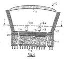
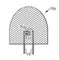
例えば、特許文献5(Yano ‘166)は、従来の発光ダイオードランプが発光ダイオードチップ、発光ダイオードチップを覆うための弾丸型透明ハウジング、電流を発光ダイオードチップに供給するためのリード、および発光ダイオードチップからの放射を均一方向に反射するためのカップ反射体を含み、発光ダイオードチップは第1の樹脂部分でカプセル封入され、これはさらに第2の樹脂部分でカプセル封入されることを開示している。特許文献5によれば、第1の樹脂部分は、カップ反射体に樹脂材料を充填し、カップ反射体の底部に発光ダイオードチップを載せ、次いでカソード電極とアノード電極を金属線でリードに電気的に接続した後その樹脂材料を硬化させることにより形成される。特許文献5によれば、リン光体は、発光ダイオードチップから放射された光Aにより励起されるように第1の樹脂部分内に分散され、励起されたリン光体は、光Aより長い波長を有する蛍光(「光B」)を発生し、光Aの一部は、リン光体を含む第1の樹脂部分内を透過し、その結果、光Aおよび光Bの混合である光Cが光照射として使用される。 For example, Patent Document 5 (Yano '166) discloses that a conventional light emitting diode lamp is a light emitting diode chip, a bullet-shaped transparent housing for covering the light emitting diode chip, a lead for supplying current to the light emitting diode chip, and a light emitting diode chip. Including a cup reflector for reflecting the radiation from the light in a uniform direction, wherein the light emitting diode chip is encapsulated in a first resin portion, which is further encapsulated in a second resin portion. . According to
上記のように、「白色LEDランプ」(つまり、白色または近白色として知覚されるランプ)が、白色白熱灯の代替候補として調査されている。白色LEDランプの代表例としては、窒化インジウムガリウム(InGaN)または窒化ガリウム(GaN)で作られ、YAGなどのリン光体でコーティングされた、青色発光ダイオードチップのパッケージが挙げられる。このようなLEDランプでは、青色発光ダイオードチップは青色を発光し、その放射を受けてリン光体は黄色の蛍光を放射する。例えば、いくつかの設計では、白色発光ダイオードランプは、セラミックリン光体層を青色発光半導体発光ダイオードの出力表面上に形成することにより製造される。発光ダイオードチップから放射された青色光線の一部は、リン光体を通過するが、発光ダイオードチップから放射された青色光線の一部は、リン光体によって吸収され、リン光体は励起され、黄色光線を放射する。リン光体を透過する発光ダイオードによって放射される青色光の一部は、リン光体によって放射される黄色光と混合される。観察者は、青色と黄色の光の混合を白色光として知覚する。他の種類では、赤色またはオレンジ色と緑色または黄緑の光線を発生するリン光体材料と組み合わせた青色または紫色の発光ダイオードチップを使用する。このようなランプでは、発光ダイオードチップによって放射される青色または紫色の光の一部は、リン光体を励起し、これによりリン光体は赤色またはオレンジ色と黄色または緑色の光線を放射する。これらの光線は、青色または紫色の光線と組み合わされて、白色光の知覚を生み出すことができる。 As noted above, “white LED lamps” (ie, lamps that are perceived as white or near white) are being investigated as alternatives to white incandescent lamps. A typical example of a white LED lamp is a blue light emitting diode chip package made of indium gallium nitride (InGaN) or gallium nitride (GaN) and coated with a phosphor such as YAG. In such an LED lamp, the blue light emitting diode chip emits blue light, and upon receiving the radiation, the phosphor emits yellow fluorescence. For example, in some designs, white light emitting diode lamps are manufactured by forming a ceramic phosphor layer on the output surface of a blue light emitting semiconductor light emitting diode. Some of the blue light emitted from the light emitting diode chip passes through the phosphor, but some of the blue light emitted from the light emitting diode chip is absorbed by the phosphor and the phosphor is excited, Emits yellow light. A portion of the blue light emitted by the light emitting diode that is transmitted through the phosphor is mixed with the yellow light emitted by the phosphor. The observer perceives a mixture of blue and yellow light as white light. Other types use blue or purple light emitting diode chips in combination with phosphor materials that generate red or orange and green or yellow-green light rays. In such lamps, a portion of the blue or violet light emitted by the light emitting diode chip excites the phosphor, which causes the phosphor to emit red or orange and yellow or green light. These rays can be combined with blue or violet rays to produce the perception of white light.
また上記のように、他の種類のLEDランプでは、紫外線を放射する発光ダイオードチップは、赤色(R)、緑色(G)、および青色(B)の光線と組み合わされる。このような「RGB LEDランプ」では、発光ダイオードチップから放射された紫外線は、リン光体を励起し、これにより、リン光体は赤色、緑色、および青色の光線を放射し、これらの混合された光線は、人間の目に白色光として知覚される。したがって、白色光は、これらの光線の混合として構成されうる。 Also, as described above, in other types of LED lamps, light emitting diode chips that emit ultraviolet light are combined with red (R), green (G), and blue (B) rays. In such “RGB LED lamps”, the UV radiation emitted from the light emitting diode chip excites the phosphor, which causes the phosphor to emit red, green, and blue rays that are mixed together. The light rays are perceived as white light by human eyes. Thus, white light can be configured as a mixture of these rays.
既存のLEDコンポーネントパッケージおよび他の電子部品が1つの器具に組み立てられる設計が提示されている。このような設計では、パッケージ化されたLEDは、回路基板に取り付けられるか、またはヒートシンクに直接取り付けられ、回路基板は、ヒートシンクに取り付けられ、ヒートシンクは、必要な駆動用電子部品とともに器具筐体に取り付けられる。多くの場合、追加の光学系(パッケージパーツの補助)も必要である。 Designs have been presented in which existing LED component packages and other electronic components are assembled into a single instrument. In such a design, the packaged LED is attached to a circuit board or directly to a heat sink, the circuit board is attached to a heat sink, and the heat sink is attached to the instrument housing along with the necessary drive electronics. It is attached. In many cases, additional optics (auxiliary package parts) are also required.
固体発光体を他の光源、例えば白熱電球の代わりに使用する場合、パッケージ化されたLEDは、従来の照明器具、例えば、中空レンズおよびレンズに取り付けられているベースプレートを含む器具とともに使用されているが、ただしベースプレートは電源に電気的に結合されている1つまたは複数の接点を持つ従来のソケット筐体を有する。例えば、電気回路基板、回路基板に取り付けられている複数のパッケージ化されたLED、および回路基板に取り付けられ、照明器具のソケット筐体に接続されるように適合されている接続ポストを含み、電源によって複数のLEDから光を照射できる、LED電球が製造されている。 When solid state light emitters are used in place of other light sources, such as incandescent bulbs, packaged LEDs are used with conventional luminaires, for example, devices that include a hollow lens and a base plate attached to the lens. However, the base plate has a conventional socket housing with one or more contacts that are electrically coupled to a power source. For example, an electrical circuit board, a plurality of packaged LEDs attached to the circuit board, and a connection post attached to the circuit board and adapted to connect to a socket housing of a luminaire LED bulbs that can emit light from a plurality of LEDs are manufactured.
固体発光体、例えば、発光ダイオードを使用して様々な用途で白色光を利用できるようにし、しかもエネルギー効率を高め、平均演色評価数(CRI Ra)を改善し、発光効率(lm/W)を上げ、および/または耐用期間を延ばすような方法が継続して求められている。 Using solid state light emitters, such as light emitting diodes, to make white light available for various applications, increasing energy efficiency, improving average color rendering index (CRI Ra), and improving luminous efficiency (lm / W) There is a continuing need for methods that increase and / or extend the useful life.
本発明の主題の第1の態様によれば、照明デバイスが実現され、このデバイスは、固体発光体の第1のグループと、第1のルミネッセンス材料と、第2のルミネッセンス材料とを含み、ここで、固体発光体の第1のグループのそれぞれは、光照射状態の場合に、近紫外線領域または紫外線領域のピーク波長を有する光を放射し、第1のルミネッセンス材料は、励起された場合に、約480nmから約490nmの範囲内の主波長(例えば、約485nm)を有する光を放射し、第2のルミネッセンス材料は、励起された場合に、約580nmから約590nmの範囲内の主波長(例えば、約585nm)を有する光を放射し、固体発光体の第1のグループのそれぞれが光照射状態の場合、(1)固体発光体の第1のグループによって放射された照明デバイスから放射される光と(2)第1のルミネッセンス材料によって放射された照明デバイスから放射される光と(3)第2のルミネッセンス材料によって放射された照明デバイスから放射される光との混合は、追加の光が存在しない場合に、1931 CIE色度図上の黒体軌跡に載っている少なくとも1つの点の40個のマクアダム楕円(または20個のマクアダム楕円、または10個のマクアダム楕円、または5個のマクアダム楕円、または3個のマクアダム楕円)内にある点を定義するx、y座標が1931 CIE色度図上にある組み合わされた光照射をもたらす。 According to a first aspect of the present inventive subject matter, a lighting device is realized, the device comprising a first group of solid state light emitters, a first luminescent material, and a second luminescent material, wherein Each of the first group of solid state light emitters emits light having a peak wavelength in the near-ultraviolet region or the ultraviolet region in the light irradiation state, and the first luminescent material is excited when excited. Emits light having a dominant wavelength in the range of about 480 nm to about 490 nm (eg, about 485 nm), and the second luminescent material, when excited, has a dominant wavelength in the range of about 580 nm to about 590 nm (eg, , About 585 nm), and each of the first group of solid state light emitters is in a light illuminated state, (1) emitted by the first group of solid state light emitters. Mixing of light emitted from a lighting device and (2) light emitted from a lighting device emitted by a first luminescent material and (3) light emitted from a lighting device emitted by a second luminescent material Is 40 McAdam ellipses (or 20 MacAdam ellipses, or 10 MacAdam ellipses) at least one point on the blackbody locus on the 1931 CIE chromaticity diagram in the absence of additional light, Or 5 MacAdam ellipses, or 3 MacAdam ellipses) resulting in combined illumination with x, y coordinates defining points within the 1931 CIE chromaticity diagram.
本発明の主題のこの態様によるいくつかの実施形態では、第1のルミネッセンス材料が、少なくとも第1のルミホールに含まれる。そのようないくつかの実施形態において、照明デバイスは、少なくとも第1のパッケージを含む。第1のパッケージは、少なくとも固体発光体の第1のグループの1つと、少なくとも第1のルミホールとを含む。 In some embodiments according to this aspect of the present inventive subject matter, the first luminescent material is included in at least the first lumihole. In some such embodiments, the lighting device includes at least a first package. The first package includes at least one of the first group of solid state light emitters and at least a first lumihole.
本発明の主題のこの態様によるいくつかの実施形態では、第2のルミネッセンス材料が、少なくとも第1のルミホールに含まれる。そのようないくつかの実施形態において、照明デバイスは、少なくとも第1のパッケージを含む。第1のパッケージは、少なくとも固体発光体の第1のグループの1つと、少なくとも第1のルミホールとを含む。 In some embodiments according to this aspect of the present inventive subject matter, a second luminescent material is included in at least the first lumihole. In some such embodiments, the lighting device includes at least a first package. The first package includes at least one of the first group of solid state light emitters and at least a first lumihole.
本発明の主題のこの態様によるいくつかの実施形態では、第1のルミネッセンス材料および第2のルミネッセンス材料が、少なくとも第1のルミホールに含まれる。そのようないくつかの実施形態において、照明デバイスは、少なくとも第1のパッケージを備える。この第1のパッケージは、固体発光体の第1のグループのうちの少なくとも1つと、少なくとも第1のルミホールを含む。 In some embodiments according to this aspect of the present inventive subject matter, a first luminescent material and a second luminescent material are included in at least the first lumiphor. In some such embodiments, the lighting device comprises at least a first package. The first package includes at least one of the first group of solid state light emitters and at least a first lumihole.
本発明の主題のこの態様によるいくつかの実施形態では、第1のルミネッセンス材料は少なくとも第1のルミホールに含まれ、第2のルミネッセンス材料は少なくとも第2のルミホールに含まれる。そのようないくつかの実施形態において、照明デバイスは、少なくとも第1のパッケージを含む。第1のパッケージは、固体発光体の第1のグループのうちの少なくとも1つと、第1のルミホールと、第2のルミホールを含む。 In some embodiments according to this aspect of the present inventive subject matter, the first luminescent material is included in at least the first lumihole, and the second luminescent material is included in at least the second lumihole. In some such embodiments, the lighting device includes at least a first package. The first package includes at least one of the first group of solid state light emitters, a first lumihole, and a second lumihole.
本発明の主題のこの態様によるいくつかの実施形態では、固体発光体の第1のグループのそれぞれは、光照射状態の場合、約380nmから約430nmまでの範囲内のピーク波長を有する光を放射する。 In some embodiments according to this aspect of the present inventive subject matter, each of the first group of solid state light emitters emits light having a peak wavelength in the range of about 380 nm to about 430 nm when illuminated. To do.
本発明の主題のこの態様によるいくつかの実施形態では、照明デバイスは、カプセル封入材を含み、またパッケージ化された固体発光体の形態をとる。 In some embodiments according to this aspect of the present inventive subject matter, the lighting device includes an encapsulant and takes the form of a packaged solid state light emitter.
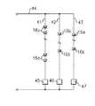
本発明の主題のこの態様によるいくつかの実施形態では、照明デバイスは、少なくとも第1の電力線と、第2の電力線と、少なくとも第1の電流調整器とをさらに含み、少なくとも固体発光体の第1のグループのうちの1つは、第1の電力線に電気的に接続されており、少なくとも固体発光体の第2のグループのうちの1つは、第2の電力線に電気的に接続されており、第1のルミネッセンス材料の少なくとも一部は、第1の固体発光体が光照射状態の場合に励起され、第2のルミネッセンス材料の少なくとも一部は、第2の固体発光体が光照射状態の場合に励起され、第1の電流調整器は、少なくとも第1および第2の電力線に供給する電流を変化させるように調整する。 In some embodiments according to this aspect of the present inventive subject matter, the lighting device further comprises at least a first power line, a second power line, and at least a first current regulator, wherein at least the first of the solid state light emitters. One of the one group is electrically connected to the first power line, and at least one of the second group of solid state light emitters is electrically connected to the second power line. And at least part of the first luminescent material is excited when the first solid state light emitter is in the light irradiation state, and at least part of the second luminescent material is in the state where the second solid state light emitter is in the light irradiation state. The first current regulator adjusts the current supplied to at least the first and second power lines to change.
本発明の主題のこの態様によるいくつかの実施形態では、固体発光体の第1のグループのそれぞれが光照射状態の場合、照明デバイスは、少なくとも85のCRI Ra、いくつかの実施形態では少なくとも90のCRI Ra、いくつかの実施形態では少なくとも92のCRI Ra、および、いくつかの実施形態では少なくとも95のCRI Raを有する光を放射する。 In some embodiments according to this aspect of the present inventive subject matter, if each of the first group of solid state light emitters is in a lighted state, the lighting device is at least 85 CRI Ra, and in some embodiments at least 90 Of light, in some embodiments at least 92 CRI Ra, and in some embodiments at least 95 CRI Ra.
本発明の主題の第2の態様によれば、照明デバイスが実現され、このデバイスは、固体発光体の第1のグループと、固体発光体の第2のグループと、第1のルミネッセンス材料と、を含み、ここで、固体発光体の第1のグループのそれぞれは、光照射状態の場合に、近紫外線領域または紫外線領域のピーク波長を有する光を放射し、固体発光体の第2のグループのそれぞれは、光照射状態の場合に、約480nmから約490nmの範囲内の主波長を有する光を放射し、第1のルミネッセンス材料は、励起された場合に、約580nmから約590nmの範囲内の主波長を有する光を放射し、固体発光体の第1および第2のグループのそれぞれが光照射状態の場合、(1)固体発光体の第1のグループによって放射された照明デバイスから放射される光と(2)固体発光体の第2のグループによって放射された照明デバイスから放射される光と(3)第1のルミネッセンス材料によって放射された照明デバイスから放射される光との混合は、追加の光が存在しない場合に、1931 CIE色度図上の黒体軌跡に載っている少なくとも1つの点の40個のマクアダム楕円(または20個のマクアダム楕円、または10個のマクアダム楕円、または5個のマクアダム楕円、または3個のマクアダム楕円)内にある点を定義するx、y座標が1931 CIE色度図上にある組み合わされた光照射をもたらす。 According to a second aspect of the present inventive subject matter, an illumination device is realized, the device comprising a first group of solid state light emitters, a second group of solid state light emitters, a first luminescent material, Wherein each of the first group of solid state light emitters emits light having a peak wavelength in the near-ultraviolet region or the ultraviolet region in the light irradiation state, and the second group of solid state light emitters. Each emits light having a dominant wavelength in the range of about 480 nm to about 490 nm when in the illuminated state, and the first luminescent material is in the range of about 580 nm to about 590 nm when excited. When emitting light having a dominant wavelength and each of the first and second groups of solid state light emitters is in a light illuminated state, (1) the light is emitted from the lighting device emitted by the first group of solid state light emitters Mixing of (2) light emitted from a lighting device emitted by a second group of solid state light emitters and (3) light emitted from a lighting device emitted by a first luminescent material is 40 McAdam ellipses (or 20 MacAdam ellipses, or 10 MacAdam ellipses, or at least one point on the blackbody locus on the 1931 CIE chromaticity diagram in the absence of additional light, or X, y coordinates defining points that lie within 5 McAdam ellipses, or 3 MacAdam ellipses) result in a combined illumination with a 1931 CIE chromaticity diagram.
本発明の主題のこの態様によるいくつかの実施形態では、第1のルミネッセンス材料が、少なくとも第1のルミホールに含まれる。そのようないくつかの実施形態において、照明デバイスは、少なくとも第1のパッケージを含む。第1のパッケージは、少なくとも固体発光体の第1のグループの1つと、少なくとも第1のルミホールとを含む。 In some embodiments according to this aspect of the present inventive subject matter, the first luminescent material is included in at least the first lumihole. In some such embodiments, the lighting device includes at least a first package. The first package includes at least one of the first group of solid state light emitters and at least a first lumihole.
本発明の主題のこの態様によるいくつかの実施形態では、照明デバイスは、少なくとも第1の電力線と、第2の電力線と、少なくとも第1の電流調整器とをさらに含み、少なくとも固体発光体の第1のグループのうちの1つは、第1の電力線に電気的に接続されており、少なくとも固体発光体の第2のグループのうちの1つは、第2の電力線に電気的に接続されており、第1のルミネッセンス材料の少なくとも一部は、第1の固体発光体が光照射状態の場合に励起され、第2のルミネッセンス材料の少なくとも一部は、第2の固体発光体が光照射状態の場合に励起され、第1の電流調整器は、少なくとも第1および第2の電力線に供給する電流を変化させるように調整する。 In some embodiments according to this aspect of the present inventive subject matter, the lighting device further comprises at least a first power line, a second power line, and at least a first current regulator, wherein at least the first of the solid state light emitters. One of the one group is electrically connected to the first power line, and at least one of the second group of solid state light emitters is electrically connected to the second power line. And at least part of the first luminescent material is excited when the first solid state light emitter is in the light irradiation state, and at least part of the second luminescent material is in the state where the second solid state light emitter is in the light irradiation state. The first current regulator adjusts the current supplied to at least the first and second power lines to change.
本発明の主題のこの態様によるいくつかの実施形態では、固体発光体の第1のグループのそれぞれ、および固体発光体の第2のグループのそれぞれが光照射状態の場合、照明デバイスは、少なくとも85のCRI Ra、いくつかの実施形態では少なくとも90のCRI Ra、いくつかの実施形態では少なくとも92のCRI Ra、および、いくつかの実施形態では少なくとも95のCRI Raを有する光を放射する。 In some embodiments according to this aspect of the present inventive subject matter, if each of the first group of solid state light emitters and each of the second group of solid state light emitters are in a light illuminated state, the lighting device is at least 85 Of light, in some embodiments at least 90 CRI Ra, in some embodiments at least 92 CRI Ra, and in some embodiments at least 95 CRI Ra.
本発明の主題の第3の態様によれば、照明デバイスが実現され、このデバイスは、固体発光体の第1のグループと、固体発光体の第2のグループと、第1のルミネッセンス材料と、を含み、ここで、固体発光体の第1のグループのそれぞれは、光照射状態の場合に、近紫外線領域または紫外線領域のピーク波長を有する光を放射し、固体発光体の第2のグループのそれぞれは、光照射状態の場合に、約580nmから約590nmの範囲内の主波長を有する光を放射し、第1のルミネッセンス材料は、励起された場合に、約480nmから約490nmの範囲内の主波長を有する光を放射し、固体発光体の第1および第2のグループのそれぞれが光照射状態の場合、(1)固体発光体の第1のグループによって放射された照明デバイスから放射される光と(2)固体発光体の第2のグループによって放射された照明デバイスから放射される光と(3)第1のルミネッセンス材料によって放射された照明デバイスから放射される光との混合は、追加の光が存在しない場合に、1931 CIE色度図上の黒体軌跡に載っている少なくとも1つの点の40個のマクアダム楕円(または20個のマクアダム楕円、または10個のマクアダム楕円、または5個のマクアダム楕円、または3個のマクアダム楕円)内にある点を定義するx、y座標が1931 CIE色度図上にある組み合わされた光照射をもたらす。 According to a third aspect of the present inventive subject matter, an illumination device is realized, the device comprising a first group of solid state light emitters, a second group of solid state light emitters, a first luminescent material, Wherein each of the first group of solid state light emitters emits light having a peak wavelength in the near-ultraviolet region or the ultraviolet region in the light irradiation state, and the second group of solid state light emitters. Each emits light having a dominant wavelength in the range of about 580 nm to about 590 nm when in the illuminated state, and the first luminescent material is in the range of about 480 nm to about 490 nm when excited. When emitting light having a dominant wavelength and each of the first and second groups of solid state light emitters is in a light illuminated state, (1) the light is emitted from the lighting device emitted by the first group of solid state light emitters Mixing of (2) light emitted from a lighting device emitted by a second group of solid state light emitters and (3) light emitted from a lighting device emitted by a first luminescent material is 40 McAdam ellipses (or 20 MacAdam ellipses, or 10 MacAdam ellipses, or at least one point on the blackbody locus on the 1931 CIE chromaticity diagram in the absence of additional light, or X, y coordinates defining points that lie within 5 McAdam ellipses, or 3 MacAdam ellipses) result in a combined illumination with a 1931 CIE chromaticity diagram.
本発明の主題のこの態様によるいくつかの実施形態では、第1のルミネッセンス材料の少なくとも一部が、少なくとも第1のルミホールに含まれる。そのようないくつかの実施形態において、照明デバイスは、少なくとも第1のパッケージを含む。第1のパッケージは、少なくとも固体発光体の第1のグループの1つと、少なくとも第1のルミホールとを含む。 In some embodiments according to this aspect of the present inventive subject matter, at least a portion of the first luminescent material is included in at least the first lumihole. In some such embodiments, the lighting device includes at least a first package. The first package includes at least one of the first group of solid state light emitters and at least a first lumihole.
本発明の主題のこの態様によるいくつかの実施形態では、照明デバイスは、少なくとも第1の電力線と、第2の電力線と、少なくとも第1の電流調整器とをさらに含み、少なくとも固体発光体の第1のグループのうちの1つは、第1の電力線に電気的に接続されており、少なくとも固体発光体の第2のグループのうちの1つは、第2の電力線に電気的に接続されており、第1のルミネッセンス材料の少なくとも一部は、第1の固体発光体が光照射状態の場合に励起され、第2のルミネッセンス材料の少なくとも一部は、第2の固体発光体が光照射状態の場合に励起され、第1の電流調整器は、少なくとも第1および第2の電力線に供給する電流を変化させるように調整する。 In some embodiments according to this aspect of the present inventive subject matter, the lighting device further comprises at least a first power line, a second power line, and at least a first current regulator, wherein at least the first of the solid state light emitters. One of the one group is electrically connected to the first power line, and at least one of the second group of solid state light emitters is electrically connected to the second power line. And at least part of the first luminescent material is excited when the first solid state light emitter is in the light irradiation state, and at least part of the second luminescent material is in the state where the second solid state light emitter is in the light irradiation state. The first current regulator adjusts the current supplied to at least the first and second power lines to change.
本発明の主題のこの態様によるいくつかの実施形態では、固体発光体の第1のグループのそれぞれ、および固体発光体の第2のグループのそれぞれが光照射状態の場合、照明デバイスは、少なくとも85のCRI Ra、いくつかの実施形態では少なくとも90のCRI Ra、いくつかの実施形態では少なくとも92のCRI Ra、および、いくつかの実施形態では少なくとも95のCRI Raを有する光を放射する。 In some embodiments according to this aspect of the present inventive subject matter, if each of the first group of solid state light emitters and each of the second group of solid state light emitters are in a light illuminated state, the lighting device is at least 85 Of light, in some embodiments at least 90 CRI Ra, in some embodiments at least 92 CRI Ra, and in some embodiments at least 95 CRI Ra.
本発明の主題の第4の態様によれば、照明の方法が提供され、この方法は、固体発光体の第1のグループに光照射を行わせ、固体発光体の第1のグループのそれぞれが近紫外線領域または紫外線領域のピーク波長を有する光を放射するようにすることと、ルミホールの第1のグループを励起し、ルミホールの第1のグループのそれぞれが約480nmから約490nmの範囲内の主波長を有する光を放射するようにすること、ルミホールの第2のグループを励起し、ルミホールの第2のグループのそれぞれが約580nmから約590nmの範囲内の主波長を有する光を放射するようにすること、を含み、ここで、(1)固体発光体の第1のグループによって放射された照明デバイスから放射される光と(2)ルミホールの第1のグループによって放射された照明デバイスから放射される光と(3)ルミホールの第2のグループによって放射された照明デバイスから放射される光との混合が、追加の光が存在しない場合に、1931 CIE色度図上の黒体軌跡に載っている少なくとも1つの点の20個のマクアダム楕円内にある点を定義するx、y座標が1931 CIE色度図上にある組み合わされた光照射をもたらす。 According to a fourth aspect of the present inventive subject matter, there is provided a method of illumination, wherein the method causes a first group of solid state light emitters to emit light, each of the first group of solid state light emitters. Emitting light having a peak wavelength in the near-ultraviolet region or the ultraviolet region and exciting the first group of lumiholes, each of the first groups of lumiholes having a main wavelength in the range of about 480 nm to about 490 nm. Radiating light having a wavelength, exciting a second group of lumiholes, each of the second group of lumiholes emitting light having a dominant wavelength in the range of about 580 nm to about 590 nm. Wherein (1) the light emitted from the lighting device emitted by the first group of solid state light emitters and (2) the first group of lumiholes The mixing of the light emitted from the illumination device emitted by (3) and the light emitted from the illumination device emitted by the second group of lumihols results in a 1931 CIE color in the absence of additional light. The x, y coordinates defining points within 20 McAdam ellipses of at least one point on the blackbody locus on the degree diagram result in combined light illumination on the 1931 CIE chromaticity diagram.
本発明の主題のこの態様によるいくつかの実施形態では、固体発光体の第1のグループのうちの少なくとも1つは、発光ダイオードを含む。 In some embodiments according to this aspect of the present inventive subject matter, at least one of the first group of solid state light emitters comprises a light emitting diode.
本発明の主題のこの態様によるいくつかの実施形態では、固体発光体の第1のグループから放射された光が、ルミホールの第1のグループを励起する。 In some embodiments according to this aspect of the present inventive subject matter, light emitted from the first group of solid state light emitters excites the first group of lumiholes.
本発明の主題のこの態様によるいくつかの実施形態では、固体発光体の第1のグループから放射された光が、ルミホールの第1のグループを励起し、固体発光体の第2のグループから放射された光が、ルミホールの第2のグループを励起する。 In some embodiments according to this aspect of the present inventive subject matter, the light emitted from the first group of solid state light emitters excites the first group of lumiholes and emits from the second group of solid state light emitters. The excited light excites a second group of lumiholes.
本発明の主題の第5の態様によれば、照明の方法が提供され、この方法は、固体発光体の第1のグループに光照射を行わせ、固体発光体の第1のグループのそれぞれが近紫外線領域または紫外線領域のピーク波長を有する光を放射するようにすることと、固体発光体の第2のグループに光照射を行わせ、固体発光体の第2のグループのそれぞれが約480nmから約490nmの範囲内の主波長を有する光を放射するようにすることと、ルミホールの第1のグループを励起し、ルミホールの第1のグループのそれぞれが約580nmから約590nmの範囲内の主波長を有する光を放射するようにすること、を含み、ここで、(1)固体発光体の第1のグループによって放射された照明デバイスから放射される光と(2)固体発光体の第2のグループによって放射された照明デバイスから放射される光と(3)ルミホールの第1のグループによって放射された照明デバイスから放射される光との混合が、追加の光が存在しない場合に、1931 CIE色度図上の黒体軌跡に載っている少なくとも1つの点の20個のマクアダム楕円内にある点を定義するx、y座標が1931 CIE色度図上にある組み合わされた光照射をもたらす。 According to a fifth aspect of the present inventive subject matter, there is provided a method of illumination, wherein the method causes a first group of solid state light emitters to emit light, each of the first group of solid state light emitters. Emitting light having a peak wavelength in the near-ultraviolet region or the ultraviolet region, and causing the second group of solid state light emitters to emit light, each of the second group of solid state light emitters starting from about 480 nm. Emitting light having a dominant wavelength in the range of about 490 nm and exciting the first group of lumiholes, each of the first groups of lumiholes having a dominant wavelength in the range of about 580 nm to about 590 nm Emitting light having: (1) light emitted from the lighting device emitted by the first group of solid state light emitters; and (2) second of the solid state light emitters. The mixing of the light emitted from the lighting device emitted by the loop and (3) the light emitted from the lighting device emitted by the first group of lumihols is 1931 CIE color when no additional light is present The x, y coordinates defining points within 20 McAdam ellipses of at least one point on the blackbody locus on the degree diagram result in combined light illumination on the 1931 CIE chromaticity diagram.
本発明の主題のこの態様によるいくつかの実施形態では、固体発光体の第1のグループのうちの少なくとも1つは、発光ダイオードを含む。 In some embodiments according to this aspect of the present inventive subject matter, at least one of the first group of solid state light emitters comprises a light emitting diode.
本発明の主題のこの態様によるいくつかの実施形態では、固体発光体の第1のグループから放射された光が、ルミホールの第1のグループを励起する。 In some embodiments according to this aspect of the present inventive subject matter, light emitted from the first group of solid state light emitters excites the first group of lumiholes.
本発明の主題の第6の態様によれば、照明の方法が提供され、この方法は、固体発光体の第1のグループに光照射を行わせ、固体発光体の第1のグループのそれぞれが近紫外線領域または紫外線領域のピーク波長を有する光を放射するようにすることと、固体発光体の第2のグループに光照射を行わせ、固体発光体の第2のグループのそれぞれが約580nmから約590nmの範囲内の主波長を有する光を放射するようにすることと、ルミホールの第1のグループを励起し、ルミホールの第1のグループのそれぞれが約480nmから約490nmの範囲内の主波長を有する光を放射するようにすること、を含み、ここで、(1)固体発光体の第1のグループによって放射された照明デバイスから放射される光と(2)固体発光体の第2のグループによって放射された照明デバイスから放射される光と(3)ルミホールの第1のグループによって放射された照明デバイスから放射される光との混合が、追加の光が存在しない場合に、1931 CIE色度図上の黒体軌跡に載っている少なくとも1つの点の20個のマクアダム楕円内にある点を定義するx、y座標が1931 CIE色度図上にある組み合わされた光照射をもたらす。 According to a sixth aspect of the present inventive subject matter, there is provided a method of illumination, wherein the method causes a first group of solid state light emitters to emit light, each of the first group of solid state light emitters being Emitting light having a peak wavelength in the near-ultraviolet region or the ultraviolet region, and causing the second group of solid state light emitters to emit light, each of the second group of solid state light emitters starting from about 580 nm. Emitting light having a dominant wavelength in the range of about 590 nm and exciting the first group of lumiholes, each of the first groups of lumiholes having a dominant wavelength in the range of about 480 nm to about 490 nm Emitting light having: (1) light emitted from the lighting device emitted by the first group of solid state light emitters; and (2) second of the solid state light emitters. The mixing of the light emitted from the lighting device emitted by the loop and (3) the light emitted from the lighting device emitted by the first group of lumihols is 1931 CIE color when no additional light is present The x, y coordinates defining points within 20 McAdam ellipses of at least one point on the blackbody locus on the degree diagram result in combined light illumination on the 1931 CIE chromaticity diagram.
本発明の主題のこの態様によるいくつかの実施形態では、固体発光体の第1のグループのうちの少なくとも1つは、発光ダイオードを含む。 In some embodiments according to this aspect of the present inventive subject matter, at least one of the first group of solid state light emitters comprises a light emitting diode.
本発明の主題のこの態様によるいくつかの実施形態では、固体発光体の第1のグループから放射された光が、ルミホールの第1のグループを励起する。 In some embodiments according to this aspect of the present inventive subject matter, light emitted from the first group of solid state light emitters excites the first group of lumiholes.
本発明の主題の第5または第6の態様によるいくつかの実施形態では、照明デバイスから放射される光の混合は、少なくとも85のCRI Ra、いくつかの実施形態では少なくとも90のCRI Ra、いくつかの実施形態では少なくとも92のCRI Ra、および、いくつかの実施形態では少なくとも95のCRI Raを有する。 In some embodiments according to the fifth or sixth aspects of the present inventive subject matter, the mixing of light emitted from the lighting device is at least 85 CRI Ra, in some embodiments at least 90 CRI Ra, Some embodiments have at least 92 CRI Ras and in some embodiments at least 95 CRI Ras.
本発明の主題は、いずれかのルミネッセンス材料が1または複数の固体発光体デバイスと交換できる実施形態を包含する。ここで、この固体発光体デバイスは、ルミネッセンス材料が励起されたときに放射される色と一致する光を(単独で、または他の光源との組み合わせにより)放射するものとする。 The subject of the invention encompasses embodiments in which any luminescent material can be exchanged for one or more solid state light emitter devices. Here, the solid state light emitter device shall emit light (alone or in combination with other light sources) that matches the color emitted when the luminescent material is excited.
本発明の主題によるいくつかの実施形態において、(1)励起された場合、約480nmから約490nm(例えば、485nm)の範囲内の主波長を有する光を放射する第1のルミネッセンス材料と、(2)励起された場合、約580nmから約590nm(例えば、585nm)の範囲内の主波長を有する光を放射する第2のルミネッセンス材料と、が含まれる。この第1および第2のルミネッセンス材料は、個別の要素にでき、または互いに組み合わせることができる。いずれの場合にも、ルミネッセンス材料の各量を選択して、最終的な光の色温度を所望のものにできる(つまり、ルミネッセンス材料の各量を変えることにより、最終的な色温度も変わりうる)。 In some embodiments according to the present inventive subject matter, (1) a first luminescent material that, when excited, emits light having a dominant wavelength in the range of about 480 nm to about 490 nm (eg, 485 nm); 2) a second luminescent material that, when excited, emits light having a dominant wavelength in the range of about 580 nm to about 590 nm (eg, 585 nm). The first and second luminescent materials can be separate elements or combined with each other. In either case, each amount of luminescent material can be selected to achieve the desired color temperature of the final light (ie, changing the amount of luminescent material can also change the final color temperature. ).
「主波長」という表現は、本明細書では、光源のスペクトルパワー分布における最大パワーを持つスペクトル線を指すことがよく知られている「ピーク波長」とは反対に、スペクトルの知覚された色、つまり光源によって放射された光を見たときに知覚される色感覚に最もよく似た色感覚を引き起こす単一の波長(つまり、「色相」におおよそ類似している)を指すよく知られている許容される意味に従って使用される。人間の目は、すべての波長を等しく知覚するわけではなく(黄色と緑色の知覚は、赤色と青色に比べてよい)、また多くの固体発光体(例えば、LED)によって放射される光は、実際には、ある範囲の波長であるため、知覚される色(つまり、主波長)は、必ずしも、最高パワーを持つ波長(ピーク波長)に等しいわけではない(多くの場合、異なる)。レーザーなどの真の単色光は、同じ主波長およびピーク波長を有する。紫外線(UV)は、定義上、非可視であり、したがって、主波長に関して定義することができない。紫外線は、バンドまたはピーク波長または波長帯によって定義される。UVは、100nmから400nmまでの範囲の波長を有するものとして定義される。濃紫色または紫およびUVなどの一部の可視色の波長には重複する部分がある。この重複する範囲は、360nmから400nmである。この範囲内の光は、主波長またはピーク波長の両方に関して定義されうる。わかりやすくするため、UV光および/または近UV光による照射または励起を特徴付けるために本明細書で使用される波長は、ピーク波長を指す。 The expression “primary wavelength” as used herein, as opposed to “peak wavelength”, which is well known to refer to the spectral line with the highest power in the spectral power distribution of the light source, It is well known to refer to a single wavelength (ie, roughly similar to “hue”) that causes a color sensation that most closely resembles the color sensation perceived when looking at the light emitted by the light source. Used according to the accepted meaning. The human eye does not perceive all wavelengths equally (the perception of yellow and green may be compared to red and blue), and the light emitted by many solid light emitters (eg LEDs) In practice, because of a range of wavelengths, the perceived color (ie, dominant wavelength) is not necessarily equal to the wavelength with the highest power (peak wavelength) (which is often different). True monochromatic light, such as a laser, has the same dominant wavelength and peak wavelength. Ultraviolet light (UV) is by definition invisible and therefore cannot be defined with respect to the dominant wavelength. Ultraviolet light is defined by band or peak wavelength or wavelength band. UV is defined as having a wavelength in the range of 100 nm to 400 nm. Some visible colors such as deep purple or purple and UV have overlapping portions. This overlapping range is from 360 nm to 400 nm. Light within this range can be defined in terms of both dominant or peak wavelengths. For clarity, the wavelength used herein to characterize irradiation or excitation with UV and / or near UV light refers to the peak wavelength.
本発明の主題は、さらに、囲まれた空間および本発明の主題による少なくとも1つの照明デバイスを含み、照明デバイスは囲まれた空間の少なくとも一部に(均一にまたは不均一に)光を照射する、被照射エンクロージャ(その容積は均一にまたは不均一に光を照射されうる)に関する。 The subject of the present invention further comprises an enclosed space and at least one lighting device according to the present inventive subject matter, wherein the lighting device irradiates light (uniformly or non-uniformly) at least a part of the enclosed space , To the illuminated enclosure, whose volume can be illuminated uniformly or non-uniformly.
本発明の主題は、さらに、表面および本明細書で説明されているような少なくとも1つの照明デバイスを含む構造を対象とし、複数の固体発光体のうちの1つまたは複数が光照射状態の場合に(または電流が1つまたは複数の電力線に供給された場合に)、照明デバイスはこの表面の少なくとも一部に光を照射する。 The subject of the present invention is further directed to a structure comprising a surface and at least one lighting device as described herein, wherein one or more of the plurality of solid state light emitters are in the illuminated state (Or when current is supplied to one or more power lines), the lighting device illuminates at least a portion of this surface.
本発明の主題は、さらに、例えば、本明細書で説明されているような少なくとも1つの照明デバイスが取り付けられている構造物、スイミングプールまたはスパ、部屋、倉庫、インジケータ、道路、駐車場、車両、標識、例えば交通標識、広告看板、船舶、おもちゃ、鏡、大型船、電子デバイス、ボート、飛行機、スタジアム、コンピュータ、リモートオーディオデバイス、リモートビデオデバイス、携帯電話、樹木、窓、LCDディスプレイ、洞窟、トンネル、庭、街灯柱などからなる群から選択された、少なくとも1つの物を含む、被照射領域を対象とする。 The subject of the invention is furthermore a structure, swimming pool or spa, room, warehouse, indicator, road, parking lot, vehicle, for example mounted with at least one lighting device as described herein Signs, traffic signs, advertising signs, ships, toys, mirrors, large ships, electronic devices, boats, airplanes, stadiums, computers, remote audio devices, remote video devices, mobile phones, trees, windows, LCD displays, caves, The irradiation area includes at least one object selected from the group consisting of a tunnel, a garden, a lamppost, and the like.
本発明の主題によるいくつかの実施形態では、照明デバイスは、さらに、少なくとも1つの追加の白色固体発光体、つまり、白色もしくは白色に近い色として知覚される光を放射するデバイス(例えば、光照射状態および/または励起状態のときに、青色発光ダイオードチップと黄色ルミホールとからなるパッケージ化されたLEDなどの、白色もしくは白色に近い色として知覚される光の組合せを放射する、少なくとも1つの発光ダイオードチップおよび/または少なくとも1つのルミホールを含むパッケージ化されたLED)を含む。 In some embodiments according to the present inventive subject matter, the lighting device further comprises at least one additional white solid state light emitter, ie, a device that emits light that is perceived as white or near-white color (eg, light illumination). At least one light emitting diode that emits a combination of light perceived as white or near-white color, such as a packaged LED consisting of a blue light emitting diode chip and a yellow lumihole when in the state and / or excited state Chip and / or packaged LED comprising at least one lumihole).
固体発光体は、飽和である場合も非飽和である場合もある。本明細書で使用されるような「飽和」という用語は、少なくとも85%の純度を持つことを意味し、「純度」という用語は、当業者によく知られている意味を有し、純度を計算する手順は当業者によく知られている。 A solid state light emitter may be saturated or unsaturated. The term “saturated” as used herein means having a purity of at least 85%, and the term “purity” has a meaning well known to those skilled in the art, The calculation procedure is well known to those skilled in the art.
本発明の主題に関係する態様は、1931 CIE(Commission International de I’Eclairage)色度図または1976 CIE色度図のいずれかで表すことができる。図1は、1931 CIE色度図を示している。図2は、1976色度図を示している。図3は、黒体軌跡を含む、1976色度図の一部を示している。当業者は、これらの図を熟知しており、またこれらの図は、容易に入手可能である(例えば、インターネットで「CIE Chromaticity Diagram」または「CIE色度図」を検索するとよい)。 Aspects related to the subject matter of the present invention can be represented in either a 1931 CIE (Commission International de I'Eclairage) chromaticity diagram or a 1976 CIE chromaticity diagram. FIG. 1 shows the 1931 CIE chromaticity diagram. FIG. 2 shows the 1976 chromaticity diagram. FIG. 3 shows a portion of a 1976 chromaticity diagram including a blackbody locus. Those skilled in the art are familiar with these diagrams, and these diagrams are readily available (eg, search the Internet for “CIE Chromaticity Diagram” or “CIE Chromaticity Diagram”).
CIE色度図は、人間の色知覚を2つのCIEパラメータxおよびy(1931色度図の場合)またはu’およびv’(1976色度図の場合)に関する地図にしたものである。CIE色度図の技術的な説明については非特許文献3を参照されたい。スペクトル色は、輪郭空間の縁の周りに分布し、これは、人間の目で知覚される色相のすべてを含む。境界線は、スペクトル色の最大彩度を表す。上記のように、1976 CIE色度図は、1931 CIE色度図に類似しているが、ただし、1976 CIE色度図は、図上の類似距離が類似の知覚された色の違いを表すように修正されている点が異なる。 The CIE chromaticity diagram maps human color perception with respect to two CIE parameters x and y (for 1931 chromaticity diagram) or u 'and v' (for 1976 chromaticity diagram). See
1931 CIE色度図では、1931 CIE色度図上の点からの偏位は、座標に関して、またはその代わりに、知覚された色の違いの程度に関する指標を与えるためにマクアダム楕円に関して、表すことができる。例えば、1931 CIE色度図上の特定の一組の座標によって定義された指定された色相からの10個のマクアダム楕円として定義される点の軌跡は、指定された色相から共通の程度だけ異なるものとそれぞれ知覚される色相からなる(また、他の数のマクアダム楕円によって特定の色相から相隔てられるものとして定義されている点の軌跡についても同様である)。 In the 1931 CIE chromaticity diagram, deviations from points on the 1931 CIE chromaticity diagram can be expressed in terms of coordinates, or alternatively, in terms of a MacAdam ellipse to give an indication of the degree of perceived color difference it can. For example, the locus of a point defined as 10 MacAdam ellipses from a specified hue defined by a specific set of coordinates on the 1931 CIE chromaticity diagram differs from the specified hue by a common degree And perceived hues (and so is the locus of points defined as being separated from a particular hue by another number of MacAdam ellipses).
1976 CIE色度図上の類似距離は、類似の知覚された色の違いを表すので、1976 CIE色度図上のある点からの偏位は、座標u’およびv’、例えば、点=(Δu’2+Δv’2)1/2に関して表すことができ、それぞれ指定された色相からの共通距離である点の軌跡は、指定された色相から共通の程度だけ異なるものとしてそれぞれ知覚される色相からなる。Since similar distances on the 1976 CIE chromaticity diagram represent similar perceived color differences, the deviation from a point on the 1976 CIE chromaticity diagram is represented by coordinates u ′ and v ′, eg, point = ( Δu ′2 + Δv ′2 )1/2 , and the trajectory of a point, which is a common distance from each specified hue, is derived from each hue perceived as being different from the specified hue by a common degree. Become.
色度座標および図1〜3に例示されているCIE色度図は、多数の書籍および他の刊行物で詳しく説明されている(例えば、参照により本明細書に組み込まれている非特許文献4の98〜107ページおよび非特許文献5の109〜110ページを参照)。 The chromaticity coordinates and the CIE chromaticity diagrams illustrated in FIGS. 1-3 are described in detail in numerous books and other publications (eg,
黒体軌跡にそって配置される色度座標(つまり、色点)は、プランクの公式E(λ)=Aλ-5/(e(B/T)−1)に従うが、ただし、Eは放射強度、λは放射波長、Tは黒体の色温度、AおよびBは定数である。黒体軌跡上にある、または黒体軌跡に近い位置にある色座標は、人間観察者にとって心地よい白色光をもたらす。1976 CIE色度図は、黒体軌跡にそった温度リスティングを含む。これらの温度リスティングは、このような温度まで上昇させられる黒体放射体の色経路を示している。加熱された物体は、白熱するときに、最初に赤みを帯びた光を発し、次いで黄色みを帯び、そして白色になり、最後に青みを帯びた光を発する。これは、黒体放射体のピーク放射に関連する波長が、温度上昇とともに徐々に短くなるため生じることであり、ウィーンの変位則に従っている。黒体軌跡上にある、または黒体軌跡の近くの位置にある光を発生する発光体は、したがって、その色温度に関して記述することができる。The chromaticity coordinates (that is, the color points) arranged along the black body locus follow Planck's formula E (λ) = Aλ-5 / (e(B / T) -1), where E is a radiation Intensity, λ is the emission wavelength, T is the color temperature of the black body, and A and B are constants. Color coordinates that are on or close to the blackbody locus provide white light that is comfortable for the human observer. The 1976 CIE chromaticity diagram includes a temperature listing along the blackbody locus. These temperature listings show the color path of a blackbody radiator that can be raised to such temperatures. When a heated object glows, it first emits reddish light, then yellowish and then white, and finally emits bluish light. This occurs because the wavelength associated with the peak radiation of the blackbody radiator gradually decreases with increasing temperature, and follows the Wien displacement law. An illuminant that generates light that is on or near the blackbody locus can therefore be described in terms of its color temperature.
本発明の主題は、付属の図面および本発明の主題の以下の詳細な説明を参照することでより詳しく理解できる。 The subject matter of the present invention may be better understood with reference to the accompanying drawings and the following detailed description of the subject matter of the present invention.
次に、本発明の主題の実施形態が示されている、付属の図面を参照しつつ、本発明の主題についてさらに詳しく以下で説明する。しかし、本発明の主題は、本明細書で述べられている実施形態に限定されるものとして解釈されるべきではない。むしろ、これらの実施形態は、本開示が詳細で完全なものとなるように、また当業者に本発明の主題の範囲が全部伝わるように用意されたものである。全体を通して、類似の番号は、類似の要素を指す。本明細書で使用されているように、「および/または」は、関連して列挙されている品目の1つまたは複数のありとあらゆる組合せを含む。 The subject matter of the invention will now be described in more detail below with reference to the accompanying drawings, in which embodiments of the subject matter of the invention are shown. However, the subject matter of the present invention should not be construed as limited to the embodiments set forth herein. Rather, these embodiments are provided so that this disclosure will be thorough and complete, and will fully convey the scope of the inventive subject matter to those skilled in the art. Like numbers refer to like elements throughout. As used herein, “and / or” includes any and all combinations of one or more of the associated listed items.
本明細書で使用されている用語は、特定の実施形態のみを説明することを目的としており、本発明の主題の範囲を制限することは意図されていない。本明細書で使用されているように、「1つの(または使わない場合もある)」および「その(使わない場合もある)」(英語原文の単数形の冠詞「a」、「an」、および「the」)は、文脈上明らかにそうでないことを示していない限り、複数形も含むことが意図されている。さらに、「含む」および/または「含むこと」という言い回しは、本明細書内で使用されている場合、記載されている特徴、整数、工程、動作、要素、および/またはコンポーネント(または構成要素)の存在を意味し、1つまたは複数の他の特徴、整数、工程、動作、要素、コンポーネント(または構成要素)、および/またはそれらからなる群の存在もしくは追加を除外しないことも理解されるであろう。 The terminology used herein is for the purpose of describing particular embodiments only and is not intended to be limiting on the scope of the inventive subject matter. As used herein, “one (or may not use)” and “that (may not use)” (the original singular articles “a”, “an”, And “the”) are intended to include the plural forms as well, unless the context clearly indicates otherwise. Further, the word “comprising” and / or “including”, as used herein, describes the described feature, integer, process, operation, element, and / or component (or component). It is also understood that it does not exclude the presence or addition of one or more other features, integers, steps, operations, elements, components (or components), and / or groups thereof. I will.
「480nmから490nmまでの固体発光体」という表現は、光照射状態の場合に、約480nmから490nmまでの範囲内の主波長を有する光を放射する固体発光体を意味する。 The expression “solid state light emitter from 480 nm to 490 nm” means a solid state light emitter that emits light having a dominant wavelength in the range from about 480 nm to 490 nm in the light irradiation state.
「580nmから590nmまでの固体発光体」という表現は、光照射状態の場合に、約580nmから590nmまでの範囲内の主波長を有する光を放射する固体発光体を意味する。 The expression “solid state light emitter from 580 nm to 590 nm” means a solid state light emitter that emits light having a dominant wavelength in the range from about 580 nm to 590 nm in the light irradiation state.
層、領域、または基板などの要素が、他の要素の「上に」ある、または「上へ」広がる、届く、伸びるなどと本明細書で言う場合、要素は、直接他の要素の上にあるか、上へ広がる、届く、伸びるか、または介在する要素も存在しうる。対照的に、要素が、他の要素の「上に直接」ある、「上へ直接」広がる、届く、伸びると本明細書で言う場合、介在する要素は存在しない。また、要素が、他の要素に「接続されている」、または「結合されている」と本明細書で言う場合、要素は、直接他の要素に接続されるか、または結合されうるか、あるいは介在する要素が存在しうる。対照的に、要素が、他の要素に「直接接続されている」か、または「直接結合されている」と本明細書で言う場合、介在する要素は存在しない。 When an element such as a layer, region, or substrate is referred to herein as being “on” or extending “up”, reaching, extending, etc. of another element, the element is directly above another element. There may also be elements that are, spread, reach, stretch or intervene. In contrast, when an element is referred to herein as being “directly above”, “directly upward”, reaching, or extending other elements, there are no intervening elements present. Also, where an element is referred to herein as being “connected” or “coupled” to another element, the element can be directly connected to or coupled to another element, or There may be intervening elements. In contrast, when an element is referred to herein as being “directly connected” or “directly coupled” to another element, there are no intervening elements present.
「第1」、「第2」などの用語は、本明細書では、様々な要素、コンポーネント、領域、層、セクション、および/またはパラメータを記述するために使用される場合があるけれども、これらの要素、コンポーネント、領域、層、セクション、および/またはパラメータは、これらの用語によって限定されるべきではない。これらの用語は、一方の要素、コンポーネント、領域、層、またはセクションを他方の領域、層、またはセクションから区別するためにのみ使用される。したがって、後述の第1の要素、コンポーネント、領域、層、またはセクションは、本発明の主題の教示から逸脱することなく第2の要素、コンポーネント、領域、層、またはセクションと称することが可能である。 Although terms such as “first”, “second” and the like may be used herein to describe various elements, components, regions, layers, sections, and / or parameters, Elements, components, regions, layers, sections, and / or parameters should not be limited by these terms. These terms are only used to distinguish one element, component, region, layer or section from the other region, layer or section. Accordingly, a first element, component, region, layer, or section described below can be referred to as a second element, component, region, layer, or section without departing from the teachings of the present inventive subject matter. .
さらに、「下側」または「下端」および「上側」または「上端」などの相対語は、本明細書では、図に示されているように一方の要素の他方の要素に対する関係を記述するために使用することができる。このような相対語は、図中に示されている配向に加えてデバイスの異なる配向をも包含することを意図されている。例えば、図中のデバイスがひっくり返された場合、他の要素の「下側」にあると記述された要素は、他の要素の「上側」で向き付けられるであろう。したがって、例示的用語「下側」は、図の特定の向きに応じて、「下側」および「上側」の両方の向きを包含しうる。同様に、図の1つのデバイスがひっくり返された場合、他の要素の「下」または「真下」にあると記述された要素は、他の要素の「上」に向き付けられるであろう。したがって、「下」または「真下」という例示的な用語は、上および下の両方の向きも包含しうる。 Further, relative terms such as “lower” or “lower” and “upper” or “upper” are used herein to describe the relationship of one element to the other as shown in the figures. Can be used for Such relative terms are intended to encompass different orientations of the device in addition to the orientation shown in the figure. For example, if the device in the figure is flipped, an element described as being “downside” of another element will be oriented “upside” of the other element. Thus, the exemplary term “lower” may encompass both “lower” and “upper” orientations, depending on the particular orientation of the figure. Similarly, when one device of the figure is flipped, an element described as being “below” or “below” another element will be oriented “above” the other element. Thus, the exemplary terms “down” or “below” can encompass both up and down orientations.
本明細書で使用されているような「照明デバイス」という表現は、デバイスが光を放射する能力を有することを示す以外に限定されるものではない。つまり、照明デバイスは、平面領域または立体領域、例えば、構造物、スイミングプールまたはスパ、部屋、倉庫、指示器、道路、駐車場、車両、標識、例えば、交通標識、広告看板、船舶、おもちゃ、鏡、大型船、電子デバイス、ボート、飛行機、スタジアム、コンピュータ、リモートオーディオデバイス、リモートビデオデバイス、携帯電話、樹木、窓、LCDディスプレイ、洞窟、トンネル、庭、街灯柱、またはエンクロージャに光を照射するデバイスまたはデバイスのアレイに光を照射するデバイス、またはエッジライト照明またはバックライト照明(例えば、バックライトポスター、標識、LCDディスプレイ)、電球の取り替え(例えば、AC白熱灯、低電圧灯、蛍光灯などの交換のため)、屋外照明に使用されるライト、セキュリティ照明に使用されるライト、外部住宅照明に使用されるライト(壁取り付け、支柱/柱取り付け)、天井器具/壁取り付け用燭台、キャビネット下照明、ランプ(床および/またはテーブルおよび/または机)、庭園燈、トラック照明、作業照明、専用照明、天井扇風機照明、古文書/美術品展示用照明、高振動/衝撃照明−作業用照明など、鏡/バニティミラー用照明に使用されるデバイス、または他の任意の発光デバイスとすることができる。 The expression “lighting device” as used herein is not limited except to indicate that the device has the ability to emit light. That is, the lighting device can be a flat or three-dimensional area, such as a structure, swimming pool or spa, room, warehouse, indicator, road, parking lot, vehicle, sign, eg, traffic sign, advertising sign, ship, toy, Light a mirror, large ship, electronic device, boat, airplane, stadium, computer, remote audio device, remote video device, mobile phone, tree, window, LCD display, cave, tunnel, garden, lamppost, or enclosure Devices that illuminate a device or an array of devices, or edge or backlight illumination (eg, backlight posters, signs, LCD displays), bulb replacement (eg, AC incandescent, low voltage, fluorescent, etc.) Light) used for outdoor lighting, Lights used for utility lighting, lights used for external residential lighting (wall mounting, column / post mounting), ceiling fixtures / wall sconce, cabinet under lighting, lamps (floor and / or table and / or desk) , Garden lamp, track lighting, work lighting, dedicated lighting, ceiling fan lighting, antique document / art exhibition lighting, high vibration / impact lighting-devices used for mirror / vanity mirror lighting, or It can be any other light emitting device.
「電流が第1の電力線に供給される場合」という表現の中で使用されているような「電流」という用語は、本明細書で説明されている対応する範囲内の主波長(および/またはピーク波長)を有する光を(複数の)固体発光体に放射させるのに十分な電流を意味する。 The term “current” as used in the expression “when current is supplied to the first power line” refers to a dominant wavelength (and / or within the corresponding range described herein). Means sufficient current to radiate light having a peak wavelength to the solid state light emitter (s).
「直接的に、または切り替え可能な形で電気的接続される」という表現は、「直接的に電気的接続される」または「切り替え可能な形で電気的接続される」を意味する。 The expression “directly or in electrical connection in a switchable manner” means “directly in electrical connection” or “in electrical connection in a switchable manner”.
1つまたは複数の固体発光体が電力線に「電気的接続される」という本明細書における記述は、電流を電力線に供給することにより電流を(複数の)固体発光体に供給できることを意味する。 The description herein that one or more solid state light emitters are “electrically connected” to a power line means that current can be supplied to the power line (s) by supplying current to the power line.
1つまたは複数のスイッチが電力線に電気的接続されるという本明細書における記述は、(1つまたは複数の)スイッチが閉じている場合に電流が電力線を通って流れることができ、また(1つまたは複数のスイッチ)が開いている場合に電流が電力線を通って流れるのを妨げられうることを意味する。 The description herein that one or more switches are electrically connected to a power line is that current can flow through the power line when the switch (s) are closed, and (1 Means that current can be prevented from flowing through the power line when one or more switches are open.
デバイス内の2つのコンポーネントが「切り替え可能な形で電気的接続される」という本明細書における記述は、2つのコンポーネントの間にスイッチが配置されており、このスイッチは開閉を選択的に行うことができ、スイッチが閉じられている場合に2つのコンポーネントは電気的接続され、スイッチが開いている場合に(つまり、スイッチが開いている期間中)2つのコンポーネントは電気的接続されないことを意味する。 The description herein that two components in a device are “switchably electrically connected” means that a switch is placed between the two components, and that the switch selectively opens and closes. Means that the two components are electrically connected when the switch is closed, and the two components are not electrically connected when the switch is open (ie, during the switch is open) .
固体発光体を指すときに本明細書で使用されているような「光照射」(または「光照射状態」または「被照射」または「照射された」)という表現は、少なくともある程度の電流が固体発光体に供給され、これにより固体発光体は、放出される放射線の少なくとも一部の波長が100nmから1000nmまでである少なくともある程度の電磁放射線を放出することを意味する。また、「光照射状態」または「被照射」という表現は、さらに、固体発光体が光を、その光が可視光であるか、または可視光であった場合に人間の目には光の連続的放射として知覚される速度で連続的にまたは間欠的に放射する状況、あるいは同じ色または異なる色の複数の固体発光体が光を、可視光であったか、または可視光である場合にそれらの色が人間の目には光の連続的放射として(また、異なる色の光が放射される場合には、それらの色の混合として)知覚されるように間欠的におよび/または交互に(「オン」時間で重なる場合も重ならない場合もある)放射している状況も包含する。 The expression “light irradiation” (or “light irradiation state” or “irradiated” or “irradiated”) as used herein when referring to a solid state light emitter means that at least some current is solid. Supplied to the illuminant, which means that the solid state illuminant emits at least some electromagnetic radiation in which the wavelength of at least part of the emitted radiation is from 100 nm to 1000 nm. In addition, the expression “light irradiation state” or “irradiated” further means that the solid-state light emitter emits light, and if the light is visible light or is visible light, it is a continuous light to the human eye. In situations where they emit continuously or intermittently at a rate perceived as radiative radiation, or when multiple solid light emitters of the same or different colors emit visible light or are visible Intermittently and / or alternately ("on" as perceived by the human eye as a continuous emission of light (and as a mixture of colors if different colors of light are emitted) It also includes radiating situations (may or may not overlap in time).
ルミホールを指すときに本明細書で使用されるような「励起状態」または「励起された」という表現は、少なくともある程度の電磁放射線(例えば、可視光、UV光、または赤外線)がルミホールに接触し、ルミホールに少なくともある程度の光を放出させることを意味する。「励起状態」または「励起された」という表現は、ルミホールが光を、人間の目には光の連続的放射として知覚される速度で連続的にまたは間欠的に放射する状況、あるいは同じ色または異なる色の複数のルミホールが光を、人間の目には光の連続的放射として(また、異なる色の光が放射される場合には、それらの色の混合として)知覚されるように間欠的におよび/または交互に(「オン」時間で重なる場合も重ならない場合もある)放射している状況を包含する。 The expression “excited state” or “excited” as used herein when referring to lumihole means that at least some electromagnetic radiation (eg, visible light, UV light, or infrared) is in contact with the lumihole. , Meaning that Lumihole emits at least some light. The expression “excited” or “excited” means that the Lumihole emits light continuously or intermittently at a rate perceived by the human eye as a continuous emission of light, or the same color or Intermittent so that multiple lumiphors of different colors perceive the light as a continuous emission of light to the human eye (and as a mixture of the colors if different colors of light are emitted) And / or alternating radiating situations (which may or may not overlap at “on” time).
本明細書で説明されている照明デバイスでは、固体発光体の「グループ」(例えば、「固体発光体の第1のグループ」)と言った場合、このグループは、単一の固体発光体または複数の固体発光体からなるものとすることができる。同様に、ルミホールの「グループ」(例えば、「ルミホールの第1のグループ」)と言った場合、このグループは、単一のルミホールまたは複数のルミホールからなるものとすることができる。 In the lighting devices described herein, reference to a “group” of solid state light emitters (eg, “first group of solid state light emitters”) refers to a single solid state light emitter or a plurality of solid state light emitters. It can be made of a solid light emitter. Similarly, when referring to a “group” of lumiholes (eg, “first group of lumiholes”), this group may consist of a single lumihole or multiple lumiholes.
別に定義されていない限り、本明細書で使用されるすべての用語(技術用語および科学用語を含む)は、本発明の主題が属している技術分野の当業者に通常理解される意味と同じ意味を有する。さらに、よく使われる辞書で定義されているような用語は、関連する技術および本明細書の背景状況における意味と矛盾しない意味を持つものと解釈すべきであり、本開示で明確に定められていない限り、理想化されたまたは過度に正式の意味で解釈されないことは理解されるであろう。配置された「隣接する」別の機構である構造または機構についての言及する場合、この隣接する機構に重なり合う部分、または基礎とする部分を有しうることもまた当業者であれば理解されるであろう。 Unless defined otherwise, all terms used herein (including technical and scientific terms) have the same meaning as commonly understood by one of ordinary skill in the art to which the subject of the invention belongs. Have In addition, terms such as those defined in commonly used dictionaries should be construed to have a meaning consistent with the meaning of the relevant technology and the context of the specification, and are clearly defined in this disclosure. It will be understood that unless otherwise understood, it is not interpreted in an idealized or overly formal sense. It will also be understood by those skilled in the art that when referring to a structure or mechanism that is another “adjacent” mechanism that is placed, it may have a portion that overlaps or is based on this adjacent mechanism. I will.
本明細書で説明されている照明デバイスでは、照明デバイスに含まれる要素の任意の組合せは、パッケージ化して1つにまとめることができる(例えば、発光ダイオードパッケージのように)。 In the lighting device described herein, any combination of elements included in the lighting device can be packaged together (eg, like a light emitting diode package).
本発明の主題によるそれぞれの照明デバイス内に収納されているルミホールは、デバイス内に収納されている固体発光体によって放射される光のどれかによって、および/またはデバイス内に収納されている他のルミホールによって放射される光のどれかによって励起されうる。様々な方式を簡単に思い付くことができ、またそれらの方式はすべて、本発明の主題に含まれる。例えば、単一の固体発光体、第1のルミホール、および第2のルミホールを含むデバイスでは、これらのルミホールは、固体発光体によって放射される光の一部が第1ルミホールを通過し、第2のルミホールを励起するような位置に配置できる(例えば、「積み重ねる」)。その代わりに、固体発光体によって放射される光はすべて、第1のルミホールまたは第2のルミホールに吸収されうるか(これにより、第1および第2のルミホールを励起し、第1および第2のルミホールに光を放射させる)、または固体発光体によって放射される光のすべては、第1のルミホールに吸収されうる(これにより、第1のルミホールを励起し、第1のルミホールに光を放射させる)。同様に、第1のルミホールによって放射される光の一部または全部は(固体発光体によって放射される光の一部または全部を吸収した結果として励起された後)、第2のルミホールによって吸収されるか、または第2のルミホールを通過しうる。その代わりに、ルミホールは、固体発光体によって放射される光が最初に第2のルミホールと接触し、次いで第1のルミホールと接触するか、またはルミホールのどれかと、他のルミホールをまだ通過しないまま接触するように配列できる。さらに、複数の固体発光体、および/または第1および/または第2のルミホールのうちの複数のルミホールは、それぞれから放射される光の一部または全部が所望のコンポーネントと接触するか、または他のコンポーネントと接触することなく照明デバイスから出るように、所望の方法で配列されうる。 Lumiholes housed in each lighting device according to the present inventive subject matter are either by light emitted by a solid state light emitter housed in the device and / or other housed in the device It can be excited by any of the light emitted by the Lumi Hall. Various schemes can be easily conceived and all are included in the subject matter of the present invention. For example, in a device that includes a single solid state light emitter, a first lumihole, and a second lumihole, these lumiholes pass a portion of the light emitted by the solid state light emitter through the first lumihole and the second Can be placed in such a position as to excite the Lumi Hall (eg, “stack”). Instead, all of the light emitted by the solid state emitter can be absorbed by the first or second lumihole (this excites the first and second lumiholes, and the first and second lumiholes). All of the light emitted by the solid state light emitter can be absorbed by the first lumihole (this excites the first lumihole and causes the first lumihole to emit light). . Similarly, some or all of the light emitted by the first lumihole (after being excited as a result of absorbing some or all of the light emitted by the solid state light emitter) is absorbed by the second lumihole. Or pass through the second lumihole. Instead, the lumihole is contacted by the light emitted by the solid state light emitter first with the second lumihole and then with the first lumihole, or with one of the lumiholes and yet not passing through the other lumihole. Can be arranged to touch. Further, the plurality of solid state light emitters, and / or the plurality of first and / or second lumiholes may be such that some or all of the light emitted from each is in contact with a desired component or the like. Can be arranged in any desired manner so as to leave the lighting device without contact with the components.
本発明の主題によるデバイスで使用される固体発光体、および本発明の対象によるデバイスで使用される(1つまたは複数の)ルミホールは、当業者に知られている固体発光体およびルミホールのうちから選択できる。様々なこのような固体発光体およびルミホールが容易に入手可能であり、また当業者によく知られており、これらのうちのどれでも使用可能である。例えば、本発明の対象を実施する際に使用されうる固体発光体およびルミホールは、各種の文献において開示されている。 The solid light emitter used in the device according to the subject of the invention and the lumihole (s) used in the device according to the subject of the invention are from solid light emitters and lumiholes known to the person skilled in the art You can choose. A variety of such solid state light emitters and lumihols are readily available and are well known to those skilled in the art, and any of these can be used. For example, solid state light emitters and lumiholes that can be used in practicing the subject matter of the present invention are disclosed in various documents.
(例えば、参照により本明細書に組み込まれている2005年12月22日に出願した「LIGHTING\DEVICE」という表題の特許文献6(発明者:Gerald H.Negley、整理番号931_003 PRO)および2006年12月21日に出願した特許文献7、
参照により本明細書に組み込まれている2006年4月24日に出願した「SHIFTING SPECTRAL CONTENT IN LEDS BY SPATIALLY SEPARATING LUMIPHOR FILMS」という表題の特許文献8(発明者:Gerald H.NegleyおよびAntony Paul van de Ven、整理番号931_006 PRO)および2007年1月19日に出願した特許文献9、
参照により本明細書に組み込まれている2006年5月26日に出願した「LIGHTING DEVICE」という表題の特許文献10(発明者:Gerald H.NegleyおよびAntony Paul van de Ven、整理番号931_009 PRO)および2007年5月22日に出願した特許文献11、
参照により本明細書に組み込まれている2006年5月26日に出願した「SOLID STATE LIGHT EMITTING DEVICE AND METHOD OF MAKING SAME」という表題の特許文献12(発明者:Gerald H.NegleyおよびNeal Hunter、整理番号931_010 PRO)および2007年5月24日に出願した特許文献13、
参照により本明細書に組み込まれている2006年5月23日に出願した「LIGHTING DEVICE AND METHOD OF MAKING」という表題の特許文献14(発明者:Gerald H.Negley、整理番号931_011 PRO)および2007年5月22日に出願した特許文献15、
参照により本明細書に組み込まれている2006年4月20日に出願した「LIGHTING DEVICE AND LIGHTING METHOD」という表題の特許文献16(発明者:Gerald H.NegleyおよびAntony Paul van de Ven、整理番号931_012 PRO)および2007年4月18日に出願した特許文献17、
参照により本明細書に組み込まれている2006年8月23日に出願した「LIGHTING DEVICE AND LIGHTING METHOD」という表題の特許文献18(発明者:Antony Paul van de VenおよびGerald H.Negley、整理番号931_034 PRO)および2007年8月22日に出願した特許文献19、
参照により本明細書に組み込まれている2006年10月12日に出願した「LIGHTING DEVICE AND METHOD OF MAKING SAME」という表題の特許文献20(発明者:Gerald H.Negley、整理番号931_041 PRO)および2007年10月11日に出願した特許文献21、
参照により本明細書に組み込まれている2007年5月8日に出願した「LIGHTING DEVICE AND LIGHTING METHOD」という表題の特許文献22(発明者:Antony Paul van de VenおよびGerald H.Negley、整理番号931_072 PRO)、および
参照により本明細書に組み込まれている2008年1月22日に出願した「ILLUMINATION DEVICE HAVING ONE OR MORE LUMIPHORS, AND METHODS OF FABRICATING SAME」という表題の特許文献23(発明者:Gerald H.NegleyおよびAntony Paul van de Ven、整理番号931_079 NP)、2007年10月26日に出願した特許文献24(発明者:Gerald H.NegleyおよびAntony Paul van de Ven、整理番号931_079 PRO)参照。)。(For example, U.S. Patent Nos. 5,099,052 and 5,200, filed Dec. 22, 2005, which is incorporated herein by reference, entitled "LIGHTING \ DEVICE" (inventor: Gerald H. Negley, Docket No. 931_003 PRO) and 2006. Patent Document 7 filed on December 21,
Patent document 8 entitled “SHIFTING SPECTRAL CONTENT IN LEDS BY SPATIALLY SEPARATING LUMIPHOR FILMS” filed on Apr. 24, 2006, which is incorporated herein by reference (Inventors: Gerald H. Negley and Antony Paul van de Ven, docket number 931_006 PRO) and Patent Document 9 filed on January 19, 2007,
Patent document 14 entitled “LIGHTING DEVICE AND METHOD OF MAKING” filed May 23, 2006, which is incorporated herein by reference (inventor: Gerald H. Negley, Docket No. 931 — 011 PRO) and 2007
Patent document 16 entitled "LIGHTING DEVICE AND LIGHTING METHOD" filed on Apr. 20, 2006, which is incorporated herein by reference (inventor: Gerald H. Negley and Antony Paul van de Ven, Docket No. 931_012 PRO) and
Patent Document 20 (Inventor: Gerald H. Negley, Docket No. 931_041 PRO) and 2007, filed Oct. 12, 2006, which is incorporated herein by reference, entitled “LIGHTING DEVICE AND METHOD OF MAKING SAME”.
Patent Document 22 entitled “LIGHTING DEVICE AND LIGHTING METHOD” filed May 8, 2007, which is incorporated herein by reference (Inventor: Antony Paul van de Ven and Gerald H. Negley, Docket No. 931_072) PRO), and
このような種類の固体発光体の例としては、無機発光ダイオードおよび有機発光ダイオードがあり、様々な種類が当技術分野では知られている。 Examples of such types of solid state light emitters include inorganic light emitting diodes and organic light emitting diodes, and various types are known in the art.
1つまたは複数のルミネッセンス材料は、所望の任意のルミネッセンス材料とすることができる。1つまたは複数のルミネッセンス材料は、下方変換または上方変換が可能であるか、あるいは両方の種類の組合せを含むことができる。例えば、1つまたは複数のルミネッセンス材料は、リン光体、シンチレータ、昼光テープ、紫外線を照射した後に可視スペクトルで発光するインクなどから選択されうる。 The one or more luminescent materials can be any desired luminescent material. The luminescent material or materials can be down-converted or up-converted, or can include a combination of both types. For example, the one or more luminescent materials may be selected from phosphors, scintillators, daylight tapes, inks that emit light in the visible spectrum after irradiation with ultraviolet light, and the like.
1つまたは複数のルミネッセンス材料は、所望の任意の形態のものとすることができる。例えば、ルミネッセンス材料は、シリコーン材料などの樹脂(つまり、ポリマーマトリクス)、エポキシ、実質的に透明なガラス、または金属酸化物材料に埋め込むことができる。 The luminescent material or materials can be of any desired form. For example, the luminescent material can be embedded in a resin such as a silicone material (ie, a polymer matrix), an epoxy, a substantially transparent glass, or a metal oxide material.
1つまたは複数のルミホールは、個別にどのようなルミホールでもよく、上記のように様々なものが当業者に知られている。例えば、(複数の)ルミホール(またはそのそれぞれ)は、1つまたは複数のリン光体を含むことができる(または本質的に1つまたは複数のリン光体からなるものとしてよいか、または1つまたは複数のリン光体からなるものとしてよい)。1または複数のルミホール(またはそのそれぞれ)は、望ましい場合に、さらに、1つまたは複数の透過率の高い(例えば、透明な、または実質的に透明な、またはいくぶん散光する)結合剤を含むことができ(または本質的に1つまたは複数の透過率の高い(例えば、透明な、または実質的に透明な、またはいくぶん散光する)結合剤からなるものとしてよいか、または1つまたは複数の透過率の高い(例えば、透明な、または実質的に透明な、またはいくぶん散光する)結合剤からなるものとしてよい)、例えば、エポキシ、シリコーン、ガラス、金属酸化物、または他の好適な材料で作ることができる(例えば、1つまたは複数の結合剤を含む与えられたルミホールでは、1つまたは複数のリン光体を1つまたは複数の結合剤の中に分散させることができる)。例えば、ルミホールは、一般に、厚ければ厚いほど、リン光体の重量パーセントが低くなりうる。しかし、ルミホールの全体的な厚さによっては、リン光体の重量パーセントは、一般的にどのような値でもよく、例えば、0.1重量パーセントから100重量パーセントまでの値とすることが可能である(例えば、純粋なリン光体に熱間等静圧圧縮成形法を施すことにより形成されるリン光体)。 One or more lumiholes may be any lumiholes individually, and various are known to those skilled in the art as described above. For example, the lumihol (s) (or each of them) can include (or consist essentially of, or one of, one or more phosphors). Or it may consist of a plurality of phosphors). The one or more lumihols (or each thereof) may further include one or more highly transmissive (eg, transparent, or substantially transparent, or somewhat diffuse) binders, if desired. Can be (or consist essentially of one or more highly transparent (eg, transparent, or substantially transparent, or somewhat diffuse) binders, or one or more transmissions Made of a binder having a high percentage (eg transparent, substantially transparent, or somewhat diffused), eg made of epoxy, silicone, glass, metal oxide, or other suitable material (E.g., for a given lumihol containing one or more binders, one or more phosphors can be separated into one or more binders). The cell can be). For example, the thicker the Lumihole, the lower the weight percent of the phosphor generally. However, depending on the overall thickness of the Lumihole, the phosphor weight percent can generally be any value, for example, from 0.1 weight percent to 100 weight percent. There are (for example, phosphors formed by subjecting pure phosphors to hot isostatic pressing).
本発明の主題によるいくつかの実施形態は、単一のルミホールを含み、他の実施形態は、複数のルミホールを含む。複数のルミホールが存在する場合、ルミホールは分離しており、および/また所望の配列構成で形成されうる。例えば、ルミホールの第1のグループは、単一の第1グループルミホールからなり、ルミホールの第2のグループは、単一の第2グループルミホールからなるものとすることができる。その代わりに、ルミホールの第1のグループおよびルミホールの第2のグループは、一緒に、単一のルミホールからなるものとすることができる(つまり、「第1グループ第2グループルミホール」)。他の実施形態では、照明デバイスは、少なくとも第1の混合ルミホールを含み、第1の混合ルミホールはルミホールの第1のグループの少なくとも1つおよびルミホールの第2のグループの少なくとも1つを含むことができる。例えば、励起されると、本明細書で指定されているような異なる範囲内の光を放射する2つ以上の種類のルミネッセンス粉体を混ぜ合わせて、単一のカプセル封入材構造物中に埋め込み、および/または単一のカプセル封入材構造物内の異なる領域を占有するようにできる。同様に、励起されると本明細書で指定されているような異なる範囲内の光を放射する各ルミネッセンス粉体をそれぞれが含む2つ以上ルミネッセンス要素は、単一のルミホールの異なる領域を占有しうる。 Some embodiments according to the present inventive subject matter include a single lumihole, while other embodiments include multiple lumiholes. When there are multiple lumiholes, the lumiholes are separated and / or can be formed in a desired arrangement. For example, the first group of lumiholes may consist of a single first group lumihole, and the second group of lumiholes may consist of a single second group lumihole. Alternatively, the first group of lumiholes and the second group of lumiholes may together comprise a single lumihole (ie, “first group second group lumihole”). In other embodiments, the lighting device includes at least a first mixed lumihole, wherein the first mixed lumihole includes at least one of the first group of lumiholes and at least one of the second group of lumiholes. it can. For example, when excited, two or more types of luminescent powders that emit light in different ranges as specified herein can be combined and embedded in a single encapsulant structure. And / or may occupy different regions within a single encapsulant structure. Similarly, two or more luminescent elements, each containing each luminescent powder that emits light in different ranges as specified herein when excited, occupy different regions of a single lumihole. sell.
1つまたは複数のルミホール(またはそのそれぞれ)は、独立に、さらに、多数のよく知られている添加物、例えば、拡散体、散乱体、着色材料などを含むことができる。 The one or more lumihols (or each thereof) can independently comprise a number of well known additives such as diffusers, scatterers, coloring materials, and the like.
本発明の主題によるいくつかの実施形態では、文献で説明されているように、複数の発光ダイオードチップのうちの1つまたは複数は、複数のルミホールのうちの1つまたは複数と一緒に1つのパッケージ内に収められ、パッケージ内の1つまたは複数のルミホールは、パッケージ内で1つまたは複数の発光ダイオードチップから相隔てて並べられ、これにより光抽出効率を改善できる(例えば、参照により本明細書に組み込まれている2005年12月22日に出願した「LIGHTING DEVICE」という表題の特許文献6(発明者:Gerald H.Negley、整理番号931_003 PRO)および2006年12月21日に出願した特許文献7を参照)。 In some embodiments according to the present inventive subject matter, as described in the literature, one or more of the plurality of light emitting diode chips is one together with one or more of the plurality of lumiholes. Encased within the package, the one or more lumiholes within the package are spaced apart from the one or more light emitting diode chips within the package, thereby improving light extraction efficiency (eg, described herein by reference). Patent document 6 (inventor: Gerald H. Negley, reference number 931_003 PRO) entitled "LIGHTING DEVICE" filed on December 22, 2005 and patent filed on December 21, 2006 Reference 7).
本発明の主題によるいくつかの実施形態では、文献で説明されているよう、2つ以上のルミホールを含み、これらのルミホールのうちの2つ以上が互いに相隔てて並べられうる(例えば、参照により本明細書に組み込まれている2006年4月24日に出願した「SHIFTING SPECTRAL CONTENT IN LEDS BY SPATIALLY SEPARATING LUMIPHOR FILMS」という表題の特許文献8(発明者:Gerald H.NegleyおよびAntony Paul van de Ven、整理番号931_006 PRO)および2007年1月19日に出願した特許文献9参照)。 Some embodiments according to the present inventive subject matter include two or more lumiholes, as described in the literature, and two or more of these lumiholes can be spaced apart from each other (eg, by reference) Patent document 8 entitled “SHIFTING SPECTRAL CONTENT IN LEDs BY SPATIALLY SEPARATING LUMIPHOR FILMS” filed on April 24, 2006, incorporated herein, (inventors: Gerald H. Negley and Antony Paul van de Ven, No. 931_006 PRO) and Patent Document 9 filed on Jan. 19, 2007).
本発明の主題のいくつかの実施形態では、一組の平行固体発光体列(つまり、互いに平行に配列された固体発光体の2つ以上の列)は、電力線と直列に配列され、これにより、電流は電力線を通して固体発光体の各列のそれぞれに供給される。本明細書で使用されているような「列」という表現は、少なくとも2つの固体発光体が電気的に直列接続されていることを意味する。このようないくつかの実施形態では、各列内の固体発光体の相対量は、一方の列と次の列とでは異なり、例えば、第1の列は、第1のパーセンテージの固体発光体を含み、固体発光体は、光照射状態のときに480nmから490nmの範囲内の波長を有する光を放射するルミネッセンス材料を励起する(残部は、光照射状態のときに580nmから590nmの範囲内の波長を有する光を放射するルミネッセンス材料を励起する)。第2の列は、第2のパーセンテージ(第1のパーセンテージと異なる)の固体発光体を含む。そうすることにより、各波長の光の相対強度を容易に調節することが可能であり、これにより、CIE色度図を効果的に扱い、および/または他の変更の補正し、および/または色温度を調節することが可能である。 In some embodiments of the present inventive subject matter, a set of parallel solid state light emitter rows (ie, two or more rows of solid state light emitters arranged parallel to each other) are arranged in series with a power line, thereby , Current is supplied to each column of solid state light emitters through power lines. The expression “column” as used herein means that at least two solid state light emitters are electrically connected in series. In some such embodiments, the relative amount of solid state light emitters in each column is different from one column to the next, for example, the first column contains a first percentage of solid state light emitters. And the solid state light emitter excites a luminescent material that emits light having a wavelength in the range of 480 nm to 490 nm when illuminated (the remainder is a wavelength in the range of 580 nm to 590 nm when illuminated) A luminescent material that emits light having: The second column includes a second percentage (different from the first percentage) of solid state light emitters. By doing so, it is possible to easily adjust the relative intensity of light at each wavelength, thereby effectively handling the CIE chromaticity diagram and / or correcting for other changes and / or color. It is possible to adjust the temperature.
本発明の主題のいくつかの実施形態では、固体発光体の各列の1つまたは複数に直接的にまたは切り替え可能な形で電気的接続されている1つまたは複数の電流調整器が含まれ、電流調整器は固体発光体の各列の1つまたは複数に供給される電流を調整するように調整されうる。このような実施形態のいくつかにおいて、(複数の)電流調整器は、1931 CIE色度図上の黒体軌跡に載る少なくとも1つの点の40個のマクアダム楕円(または20個のマクアダム楕円、または10個のマクアダム楕円、または5個のマクアダム楕円、または3個のマクアダム楕円)内に光の混合を維持するように自動的に調製される。 Some embodiments of the present inventive subject matter include one or more current regulators that are electrically connected directly or in a switchable manner to one or more of each row of solid state light emitters. The current regulator can be adjusted to adjust the current supplied to one or more of each row of solid state light emitters. In some of such embodiments, the current regulator (s) are 40 MacAdam ellipses (or 20 MacAdam ellipses) of at least one point on the blackbody locus on the 1931 CIE chromaticity diagram, or 10 MacAdam ellipses, or 5 MacAdam ellipses, or 3 MacAdam ellipses) automatically adjusted to maintain light mixing.
1931 CIE色度図および/または1976 CIE色度図上の黒体軌跡への近接度(例えば、マクアダム楕円内の)に関する本明細書で説明されている混合光に関して、本発明の主題は、さらに、2700K、3000K、または3500Kの色温度を有する黒体軌跡上の光の近くに位置するそのような混合光を対象とする、つまり、
第1の線分が第1の点と第2の点を結び、第2の線分が第2の点と第3の点を結び、第3の線分が第3の点と第4の点を結び、第4の線分が第4の点と第5の点を結び、第5の線分が第5の点と第1の点を結び、第1の点は0.4578、0.4101のx、y座標を有し、第2の点は0.4813、0.4319のx、y座標を有し、第3の点は0.4562、0.4260のx、y座標を有し、第4の点は0.4373、0.3893のx、y座標を有し、第5の点は0.4593、0.3944のx、y座標を有する、第1、第2、第3、第4、および第5の線分によって囲まれた1931 CIE色度図上の領域内にある点を定義するx、y色座標を有する混合光(つまり、2700Kに近い)、または
第1の線分が第1の点と第2の点を結び、第2の線分が第2の点と第3の点を結び、第3の線分が第3の点と第4の点を結び、第4の線分が第4の点と第5の点を結び、第5の線分が第5の点と第1の点を結び、第1の点は0.4338、0.4030のx、y座標を有し、第2の点は0.4562、0.4260のx、y座標を有し、第3の点は0.4299、0.4165のx、y座標を有し、第4の点は0.4147、0.3814のx、y座標を有し、第5の点は0.4373、0.3893のx、y座標を有する、第1、第2、第3、第4、および第5の線分によって囲まれた1931 CIE色度図上の領域内にある点を定義するx、y色座標を有する混合光(つまり、3000Kに近い)、または
第1の線分が第1の点と第2の点を結び、第2の線分が第2の点と第3の点を結び、第3の線分が第3の点と第4の点を結び、第4の線分が第4の点と第5の点を結び、第5の線分が第5の点と第1の点を結び、第1の点は0.4073、0.3930のx、y座標を有し、第2の点は0.4299、0.4165のx、y座標を有し、第3の点は0.3996、0.4015のx、y座標を有し、第4の点は0.3889、0.3690のx、y座標を有し、第5の点は0.4147、0.3814のx、y座標を有する、第1、第2、第3、第4、および第5の線分によって囲まれた1931 CIE色度図上の領域内にある点を定義するx、y色座標を有する混合光(つまり、3500Kに近い)を対象とする。With respect to the mixed light described herein with respect to proximity to a blackbody locus on a 1931 CIE chromaticity diagram and / or 1976 CIE chromaticity diagram (eg, within a MacAdam ellipse), the subject of the present invention is further For such mixed light located near a light on a blackbody locus having a color temperature of 2700K, 3000K, or 3500K, i.e.
The first line segment connects the first point and the second point, the second line segment connects the second point and the third point, and the third line segment connects the third point and the fourth point. Connect the points, the fourth line segment connects the fourth point and the fifth point, the fifth line segment connects the fifth point and the first point, and the first point is 0.4578, 0 The second point has x, y coordinates of 0.4813, 0.4319, and the third point has x, y coordinates of 0.4562, 0.4260. The fourth point has x, y coordinates of 0.4373, 0.3893, the fifth point has x, y coordinates of 0.4593, 0.3944, first, second, Mixed light with x, y color coordinates (ie, close to 2700K) defining points within a region on the 1931 CIE chromaticity diagram surrounded by the third, fourth and fifth line segments, or 1 segment is the first point and the second Connect the points, the second line segment connects the second point and the third point, the third line segment connects the third point and the fourth point, and the fourth line segment is the fourth point And the fifth point, the fifth line segment connects the fifth point and the first point, the first point has x, y coordinates of 0.4338, 0.4030, The point has x, y coordinates of 0.4562, 0.4260, the third point has x, y coordinates of 0.4299, 0.4165, and the fourth point is 0.4147, 0. Surrounded by first, second, third, fourth, and fifth line segments having x, y coordinates of 3814, and a fifth point having x, y coordinates of 0.4373, 0.3893 A mixed light having x, y color coordinates (ie, close to 3000K), or a first line segment defining the point within the region on the generated 1931 CIE chromaticity diagram. And the second line segment is the second Connecting the point and the third point, the third line segment connecting the third point and the fourth point, the fourth line segment connecting the fourth point and the fifth point, and the fifth line segment Connects the fifth point and the first point, the first point has x, y coordinates of 0.4073, 0.3930, and the second point has x, y of 0.4299, 0.4165. The third point has x, y coordinates of 0.3996, 0.4015, the fourth point has x, y coordinates of 0.3889, 0.3690, The point is in the region on the 1931 CIE chromaticity diagram surrounded by the first, second, third, fourth, and fifth line segments having x, y coordinates of 0.4147, 0.3814 The target is mixed light having x and y color coordinates that define a point (ie, close to 3500K).
本発明の主題のいくつかの実施形態では、さらに、各列の1つまたは複数に電気的接続された1つまたは複数のスイッチが含まれ、スイッチは、各列上の(複数の)固体発光体に流される電流のオン、オフを選択的に切り替える。 In some embodiments of the present inventive subject matter, further includes one or more switches electrically connected to one or more of each column, the switches comprising solid state light emission (s) on each column It selectively switches on and off the current flowing through the body.
本発明の主題のいくつかの実施形態では、1つまたは複数の電流調整器および/または1つまたは複数のスイッチは、照明デバイスからの出力の検出された変化(例えば、黒体軌跡からの偏位の程度)に応じて、または所望のパターン(例えば、組み合わされた放射光の相関する色温度の変化など、昼または夜の時間に基づく)に従って、1つまたは複数の各列を通る電流を自動的に遮断および/または調整する。 In some embodiments of the present inventive subject matter, one or more current regulators and / or one or more switches may detect a detected change in output from a lighting device (e.g., deviation from a blackbody trajectory). The current through each column or columns according to the desired pattern (eg, based on day or night time, such as a correlated color temperature change of the combined radiation). Automatically shut off and / or adjust.
本発明の主題のいくつかの実施形態では、さらに、温度を検出し、温度が変化したときに、そのような温度変化を補正するため1つまたは複数の電流調整器および/または1つまたは複数のスイッチに1つまたは複数の各列を通る電流の遮断および/または調整を自動的に行わせる1つまたは複数のサーミスタが含まれる。 In some embodiments of the present inventive subject matter, one or more current regulators and / or one or more are further provided for detecting temperature and correcting such temperature change when the temperature changes. One or more thermistors are included that cause the switches to automatically interrupt and / or regulate the current through each of the one or more columns.
本発明の主題によるいくつかの照明デバイスでは、さらに、1つまたは複数の回路コンポーネント、例えば、照明デバイス内の1つまたは複数の固体発光体のうちの少なくとも1つを通る電流の供給および制御を行うための駆動電子回路が含まれる。当業者は、固体発光体を通過する電流の供給および制御を行うための様々な方法を熟知しており、またそのような方法は、本発明の主題のデバイス内で使用されうる。例えば、そのような回路は、少なくとも1つの接点、少なくとも1つのリードフレーム、少なくとも1つの電流調整器、少なくとも1つの電力制御装置、少なくとも1つの電圧制御装置、少なくとも1つブースト、少なくとも1つのキャパシタ、および/または少なくとも1つのブリッジ整流器を含むことができ、当業者であればそのようなコンポーネントを熟知しており、また望ましい電流特性を満たすように適切な回路を設計することが容易にできる。例えば、本発明の主題を実施する際に使用されうる回路は、各種の文献において開示されている。 Some lighting devices according to the present inventive subject matter further provide for the supply and control of current through one or more circuit components, eg, at least one of one or more solid state light emitters in the lighting device. Drive electronics to do is included. Those skilled in the art are familiar with various methods for providing and controlling the current passing through a solid state light emitter, and such methods can be used in the devices of the present subject matter. For example, such a circuit includes at least one contact, at least one lead frame, at least one current regulator, at least one power controller, at least one voltage controller, at least one boost, at least one capacitor, And / or can include at least one bridge rectifier, and those skilled in the art are familiar with such components and can easily design suitable circuits to meet desired current characteristics. For example, circuits that may be used in practicing the present subject matter are disclosed in various references.
(例えば、参照によりその全体が本明細書に組み込まれている2006年6月1日に出願した「LIGHTING DEVICE WITH COOLING」という表題の特許文献25(発明者:Thomas G.Coleman、Gerald H.Negley、およびAntony Paul van de Ven、整理番号931_007 PRO)および2007年1月24日に出願した特許文献26、
参照によりその全体が本明細書に組み込まれている2006年5月31日に出願した「LIGHTING DEVICE AND METHOD OF LIGHTING」という表題の特許文献27(発明者:Gerald H.Negley、整理番号931_018 PRO)および2007年5月30日に出願した特許文献28、
参照によりその全体が本明細書に組み込まれている2006年9月13日に出願した「BOOST/FLYBACK POWER SUPPLY TOPOLOGY WITH LOW SIDE MOSFET CURRENT CONTROL」という表題の特許文献29(発明者:Peter Jay Myers、整理番号931_020 PRO)および2007年9月13日に出願した「CIRCUITRY FOR SUPPLYING ELECTRICAL POWER TO LOADS」という表題の特許文献30、
2007年6月14日に出願した「DEVICES AND METHODS FOR POWER CONVERSION FOR LIGHTING DEVICES WHICH INCLUDE SOLID STATE LIGHT EMITTERS」という表題の特許文献31(発明者:Peter Jay Myers、整理番号931_076 PRO)、
参照によりその全体が本明細書に組み込まれている2007年11月28日に出願した「SOLID STATE LIGHTING DEVICES AND METHODS OF MANUFACTURING THE SAME」という表題の特許文献32(発明者:Gerald H.Negley、Antony Paul van de Ven、Kenneth R.Byrd、およびPeter Jay Myers、整理番号931_082 PRO)および2008年4月1日に出願した特許文献33、および
参照によりその全体が本明細書に組み込まれている2008年1月23日に出願した「FREQUENCY CONVERTED DIMMING SIGNAL GENERATION」という表題の特許文献34(発明者:Peter Jay Myers、Michael Harris、およびTerry Given、整理番号931_085 PRO)および2008年3月27日に出願した特許文献35参照)。(For example, Patent Document 25 entitled “LIGHTING DEVICE WITH COOLING” filed on June 1, 2006, which is incorporated herein by reference in its entirety, (Inventor: Thomas G. Coleman, Gerald H. Negley. , And Antony Paul van de Ven, Docket No. 931_007 PRO) and Patent Document 26 filed on January 24, 2007,
Patent document 27 entitled "LIGHTING DEVICE AND METHOD OF LIGHTING" filed May 31, 2006, which is incorporated herein by reference in its entirety (inventor: Gerald H. Negley, Docket No. 931_018 PRO) And
Patent document 29 entitled “BOOST / FLYBACK POWER SUPPLY TOPOLOGY WITH LOW SIDE MOSFET CURRENT CONTROL” filed on September 13, 2006, which is incorporated herein by reference in its entirety (inventor: Peter Jay Myers, Reference No. 931_020 PRO) and Patent Document 30 entitled “CIRCUITRY FOR SUPPLYING ELECTRICAL POWER TO LOADS” filed on September 13, 2007,
Patent Document 31 entitled “DEVICES AND METHODS FOR POWER CONVERSION FOR LIGHTING DEVICES WHICH INCLUDE SOLID STATE LIGHT EMITTERS” filed on June 14, 2007 (inventor: Peter Jay Myers, reference number 931_076 PRO),
Patent Document 32 entitled “SOLID STATE LIGHTING DEVICES AND METHODS OF MANUFACTURING THE SAME” filed on Nov. 28, 2007, which is incorporated herein by reference in its entirety (inventor: Gerald H. Negley, Antonio) Paul van de Ven, Kenneth R. Byrd, and Peter Jay Myers, docket number 931 — 082 PRO) and US Pat. Patent document 34 entitled "FREQUENCY CONVERTED DIMMING SIGNAL GENERATION" filed on January 23 (inventors: Peter Jay Myers, Michael Harris, and Terry Given, reference number 931_085 PRO) and March 27, 2008 Patent Document 35, filed).
それに加えて、当業者であれば、多くの異なる種類の照明用の様々な取付構造物を熟知しており、またそのような構造はどれも、本発明の主題に従って使用できる。 In addition, those skilled in the art are familiar with various mounting structures for many different types of lighting, and any such structures can be used in accordance with the present subject matter.
例えば、本発明の主題を実施する際に使用されうる固定具、他の取付構造物、および完成照明アセンブリは、各種の文献において開示されている。 For example, fixtures, other mounting structures, and finished lighting assemblies that may be used in practicing the present inventive subject matter are disclosed in various references.
(例えば、参照によりその全体が本明細書に組み込まれている2005年12月21日に出願した「LIGHTING DEVICE」という表題の特許文献36(発明者:Gerald H.Negley、Antony Paul van de Ven、およびNeal Hunter、整理番号931_002 PRO)および2006年12月20日に出願した特許文献37、
参照によりその全体が本明細書に組み込まれている2006年5月5日に出願した「LIGHTING DEVICE」という表題の特許文献38(発明者:Antony Paul van de Ven、整理番号931_008 PRO)および2007年5月3日に出願した特許文献39、
参照によりその全体が本明細書に組み込まれている2006年5月31日に出願した「LIGHTING DEVICE AND METHOD OF LIGHTING」という表題の特許文献40(発明者:Gerald H.Negley、Antony Paul van de Ven、およびThomas G.Coleman、整理番号931_017 PRO)および2007年5月30日に出願した特許文献41、
参照によりその全体が本明細書に組み込まれている2006年9月18日に出願した「LIGHTING DEVICES, LIGHTING ASSEMBLIES, FIXTURES AND METHODS OF USING SAME」という表題の特許文献42(発明者:Antony Paul van de Ven、整理番号931_019 PRO)および2007年9月17日に出願した特許文献43、
参照によりその全体が本明細書に組み込まれている2006年9月21日に出願した「LIGHTING ASSEMBLIES, METHODS OF INSTALLING SAME, AND METHODS OF REPLACING LIGHTS」という表題の特許文献44(発明者:Antony Paul van de VenおよびGerald H.Negley、整理番号931_021 PRO)および2007年9月21日に出願した特許文献45、
参照によりその全体が本明細書に組み込まれている2006年11月13日に出願した「LIGHTING DEVICE, ILLUMINATED ENCLOSURE AND LIGHTING METHODS」という表題の特許文献46(発明者:Gerald H.Negley、整理番号931_026 PRO)および2007年11月13日に出願した特許文献47、
参照によりその全体が本明細書に組み込まれている2006年11月14日に出願した「LIGHT ENGINE ASSEMBLIES」という表題の特許文献48(発明者:Paul Kenneth PickardおよびGary David Trott、整理番号931_036 PRO)および2007年11月13日に出願した特許文献49、
参照によりその全体が本明細書に組み込まれている2006年11月14日に出願した「LIGHTING ASSEMBLIES AND COMPONENTS FOR LIGHTING ASSEMBLIES」という表題の特許文献50(発明者:Gary David TrottおよびPaul Kenneth Pickard、整理番号931_037 PRO)および2007年4月18日に出願した特許文献51、
参照によりその全体が本明細書に組み込まれている2006年10月23日に出願した「LIGHTING DEVICES AND METHODS OF INSTALLING LIGHT ENGINE HOUSINGS AND/OR TRIM ELEMENTS IN LIGHTING DEVICE HOUSINGS」という表題の特許文献52(発明者:Gary David TrottおよびPaul Kenneth Pickard、整理番号931_038 PRO)および2007年10月23日に出願した特許文献53、
参照によりその全体が本明細書に組み込まれている2006年11月30日に出願した「LED DOWNLIGHT WITH ACCESSORY ATTACHMENT」という表題の特許文献54(発明者:Gary David Trott、Paul Kenneth Pickard、およびEd Adams、整理番号931_044 PRO)、
参照によりその全体が本明細書に組み込まれている2007年5月7日に出願した「LIGHT FIXTURES, LIGHTING DEVICES, AND COMPONENTS FOR THE SAME」という表題の特許文献55(発明者:Paul Kenneth Pickard、Gary David Trott、およびEd Adams、整理番号931_055 PRO)および2007年11月30日に出願した特許文献56(発明者:Gary David Trott、Paul Kenneth Pickard、およびEd Adams、整理番号931_055 NP)、
参照によりその全体が本明細書に組み込まれている2007年5月4日に出願した「LIGHTING FIXTURE」という表題の特許文献57(発明者:Paul Kenneth Pickard、James Michael LAY、およびGary David Trott、整理番号931_069 PRO)、
参照によりその全体が本明細書に組み込まれている2007年5月7日に出願した「LIGHT FIXTURES AND LIGHTING DEVICES」という表題の特許文献58(発明者:Gary David TrottおよびPaul Kenneth Pickard、整理番号931_071 PRO)、および
参照によりその全体が本明細書に組み込まれている2008年2月15日に出願した「LIGHT FIXTURES AND LIGHTING DEVICES」という表題の特許文献59(発明者:Paul Kenneth PickardおよびGary David Trott、整理番号931_086 PRO)および2008年3月18日に出願した特許文献60参照)。(For example, Patent Document 36 entitled “LIGHTING DEVICE” filed on Dec. 21, 2005, which is hereby incorporated by reference in its entirety, (Inventor: Gerald H. Negley, Antonio Paul van de Ven, And Neal Hunter, Docket No. 931_002 PRO) and Patent Document 37 filed on Dec. 20, 2006,
Patent Document 38 (Inventor: Antony Paul van de Ven, Docket No. 931_008 PRO) filed May 5, 2006, which is incorporated herein by reference in its entirety, and 2007. Patent Document 39 filed on May 3,
Patent document 40 entitled "LIGHTING DEVICE AND METHOD OF LIGHTING" filed May 31, 2006, which is incorporated herein by reference in its entirety (inventor: Gerald H. Negley, Antony Paul van de Ven). , And Thomas G. Coleman, Docket No. 931 — 017 PRO) and US Pat.
Patent document 48 entitled "LIGHT ENGINE ASSEMBLIES", filed November 14, 2006, which is incorporated herein by reference in its entirety (inventor: Paul Kenneth Pickard and Gary David Trot, Docket No. 931_036 PRO) And Patent Document 49 filed on November 13, 2007,
Patent document 50 entitled “LIGHTING ASSEMBLIES AND COMPONENTS FOR LIGHTING ASSEMBLIES” filed on Nov. 14, 2006, which is incorporated herein by reference in its entirety (inventors: Gary David Trott and Paul Kenneth Pickard, Organized No. 931_037 PRO) and Patent Document 51 filed on April 18, 2007,
Patent Document 52 entitled “LIGHTING DEVICES AND METHODS OF INSTALLING LIGHT ENGINE HOUSINGS AND / OR TRIM ELEMENTS IN LIGHTING DEVICE HOUSINGS” filed on Oct. 23, 2006, which is incorporated herein by reference in its entirety. Gary David Trot and Paul Kenneth Pickcard, Docket No. 931_038 PRO) and Patent Document 53 filed on Oct. 23, 2007,
Patent document 54 entitled “LED DOWNLIGHT WITH ACCESSORY ATTACHMENT” filed on Nov. 30, 2006, which is incorporated herein by reference in its entirety (inventors: Gary David Trott, Paul Kenneth Pickard, and Ed Adams). , Reference number 931_044 PRO),
Patent document 55 entitled “LIGHT FIXTURES, LIGHTING DEVICES, AND COMPONENTS FOR THE SAME” filed May 7, 2007, which is incorporated herein by reference in its entirety (inventor: Paul Kenneth Pickard, Gary David Trott and Ed Adams, docket number 931_055 PRO) and Patent Document 56 filed on Nov. 30, 2007 (inventor: Gary David Trott, Paul Kenneth Pickard, and Ed Adams, docket number 931_055 NP),
Patent document 57 entitled "LIGHTING FIXTURE" filed May 4, 2007, which is incorporated herein by reference in its entirety (inventors: Paul Kenneth Pickard, James Michael LAY, and Gary David Trot, Organized Number 931_069 PRO),
Patent document 58 entitled “LIGHT FIXTURES AND LIGHTING DEVICES” filed May 7, 2007, which is incorporated herein by reference in its entirety (inventors: Gary David Trott and Paul Kenneth Pickard, Docket No. 931_071). PRO), and U.S. Pat. No. 6,057,097, entitled “LIGHT FIXTURES AND LIGHTING DEVICES”, filed Feb. 15, 2008, which is incorporated herein by reference in its entirety. (Inventors: Paul Kenneth Pickard and Gary David Trott) No. 931_086 PRO) and Patent Document 60 filed on Mar. 18, 2008).
本発明の主題によるいくつかの照明デバイスでは、さらに、1つまたは複数の電源、例えば、1つまたは複数の電池および/または太陽電池、および/または1つまたは複数の標準AC電源プラグが含まれる。 Some lighting devices according to the present inventive subject matter further include one or more power sources, such as one or more batteries and / or solar cells, and / or one or more standard AC power plugs. .
本発明の主題による照明デバイスは、固体発光体およびルミホールを望む数だけ含むことができる。例えば、本発明の主題による照明デバイスは、50個以上の固体発光体を含むか、または100個以上の固体発光体などを含むことができる。 A lighting device according to the present inventive subject matter can include as many solid state light emitters and lumiholes as desired. For example, a lighting device according to the present inventive subject matter can include 50 or more solid state light emitters, or can include 100 or more solid state light emitters and the like.
本発明の主題の照明デバイス内の可視光源は、所望の方法で配列され、取り付けられ、電力を供給され、また所望のハウジングもしくは固定具に取り付けられうる。好適な配列構成の代表例については各種の文献において説明されている。 The visible light source in the subject lighting device of the present invention can be arranged, attached, powered, and attached to the desired housing or fixture in any desired manner. Representative examples of suitable arrangements are described in various documents.
例えば、参照によりその全体が本明細書に組み込まれている2008年1月22日に出願した「FAULT TOLERANT LIGHT EMITTERS, SYSTEMS INCORPORATING FAULT TOLERANT LIGHT EMITTERS AND METHODS OF FABRICATING FAULT TOLERANT LIGHT EMITTERS」という表題の特許文献61(発明者:Gerald H.NegleyおよびAntony Paul van de Ven、整理番号931_056 NP)、2007年1月22日に出願した「HIGH VOLTAGE SOLID STATE LIGHT EMITTER」という表題の特許文献62(発明者:Gerald H.Negley、整理番号931_056 PRO)、2007年10月26日に出願した「FAULT TOLERANT LIGHT EMITTERS, SYSTEMS INCORPORATING FAULT TOLERANT LIGHT EMITTERS AND METHODS OF FABRICATING FAULT TOLERANT LIGHT EMITTERS」という表題の特許文献63(発明者:Gerald H.NegleyおよびAntony Paul van de Ven、整理番号931_056 PRO2)、および2007年11月9日に出願した特許文献64(整理番号931_056 PRO3)、
参照によりその全体が本明細書に組み込まれている2008年1月22日に出願した「ILLUMINATION DEVICES USING EXTERNALLY INTERCONNECTED ARRAYS OF LIGHT EMITTING DEVICES, AND METHODS OF FABRICATING SAME」という表題の特許文献65(発明者:Gerald H.NegleyおよびAntony Paul van de Ven、整理番号931_078 NP)、2007年10月26日に出願した特許文献66(発明者:Gerald H.NegleyおよびAntony Paul van de Ven、整理番号931_078 PRO)、および2007年11月9日に出願した特許文献67(整理番号931_078 PRO2)、
参照によりその全体が本明細書に組み込まれている2008年1月22日に出願した「ILLUMINATION DEVICE HAVING ONE OR MORE LUMIPHORS, AND METHODS OF FABRICATING SAME」という表題の特許文献23(発明者:Gerald H.NegleyおよびAntony Paul van de Ven、整理番号931_079 NP)、2007年10月26日に出願した特許文献24(発明者:Gerald H.NegleyおよびAntony Paul van de Ven、整理番号931_079 PRO)参照。For example, a patent document entitled “FAULT TOLERANT LIGHT EMITTERS, SYSTEMS INCORPORATING FAULT TOLERANT LIGHT EMITTERS AND METHODS OF FABRICATING FAULT TOLERANT LIGHT EMITTERS” filed on Jan. 22, 2008, which is incorporated herein by reference in its entirety. 61 (inventor: Gerald H. Negley and Antony Paul van de Ven, reference number 931_056 NP), patent document 62 entitled “HIGH VOLTAGE SOLID STATE LIGHT EMITTER” filed on January 22, 2007 (inventor: Gerald) H. Negley, Reference Number 931_056 PRO), Patent Document 63 entitled “FAULT TOLERANT LIGHT EMITTERS, SYSTEMS INCORPORATING FAULT TOLERANT LIGHT EMITTERS AND METHODS OF FABRICATING FAULT TOLERANT LIGHT EMITTERS” filed on October 26, 2007 (inventor: Gerald H. Negle y and Antony Paul van de Ven, reference number 931_056 PRO2), and Patent Document 64 (reference number 931_056 PRO3) filed on November 9, 2007,
Patent Document 65 entitled “ILLUMINATION DEVICES USING EXTERNALLY INTERCONNECTED ARRAYS OF LIGHT EMITTING DEVICES, AND METHODS OF FABRICATING SAME” filed on January 22, 2008, which is incorporated herein by reference in its entirety. Gerald H. Negley and Antony Paul van de Ven, Docket No. 931_078 NP), Patent Document 66 filed on Oct. 26, 2007 (Inventor: Gerald H. Negley and Antonio Paul van de Ven, Docket No. 931_078 PRO) And Patent Document 67 (reference number 931_078 PRO2) filed on November 9, 2007,
それに加えて、当業者であれば、様々な配列構成、取付方式、電力供給装置、ハウジング、および固定具を熟知しており、そのような配列構成、方式、装置、ハウジング、および固定具は、本発明の主題に関連して使用されうる。本発明の主題の照明デバイスは、所望の電源に電気的接続され(または、選択的に接続され)ようにでき、当業者であれば様々なそのような電源を熟知している。 In addition, those skilled in the art are familiar with various arrangements, mounting methods, power supply devices, housings, and fixtures, such arrangements, methods, devices, housings, and fixtures are It can be used in connection with the subject matter of the present invention. The lighting device of the present inventive subject matter can be electrically connected (or selectively connected) to a desired power source, and those skilled in the art are familiar with a variety of such power sources.
本発明の主題によるデバイスは、さらに、1つまたは複数の耐用期間の長い冷却デバイス(例えば、極端に長い耐用期間を有するファン)を含むことができる。このような耐用期間の長い(複数の)冷却デバイスは、「中国扇子」などの空気を動かす圧電材料または磁気抵抗材料(例えば、MR、GMR、および/またはHMR材料)を含むことができる。本発明の主題によるデバイスを冷却する際に、典型的には、10から15℃の温度低下を誘発するために境界層を破壊するのに十分な量の空気があればよい。したがって、このような場合、強い「風」または大きな流体流量(大きなCFM)は、典型的には必要ない(これにより、従来のファンが必要なくなる)。 Devices according to the present inventive subject matter can further include one or more long-life cooling devices (eg, fans having extremely long lifetimes). Such long-life cooling device (s) may include a piezoelectric or magnetoresistive material (eg, MR, GMR, and / or HMR material) that moves air, such as a “Chinese fan”. When cooling a device according to the present inventive subject matter, there typically needs to be a sufficient amount of air to break the boundary layer to induce a temperature drop of 10 to 15 ° C. Thus, in such cases, strong “wind” or high fluid flow (large CFM) is typically not needed (thus eliminating the need for conventional fans).
さらに、本発明の主題によるデバイスは、放射光の投影される性質をさらに変更するための二次光学系を含むことができる。このような二次光学系は、当業者によく知られており、したがって、本明細書では詳しく説明される必要のないものである−そのような二次光学系は、必要ならば使用してもよい。 Furthermore, the device according to the present inventive subject matter can include secondary optics for further modifying the projected nature of the emitted light. Such secondary optics are well known to those skilled in the art and therefore need not be described in detail herein-such secondary optics can be used if necessary. Also good.
さらに、本発明の主題によるデバイスは、センサーまたは充電器もしくはカメラなどを含むことができる。例えば、当業者であれば、1つまたは複数の出現を検出し(例えば、物体または人の動きを検出するモーション検出器)、そのような検出結果に応じて、光の照射をトリガーするデバイスを熟知しており、また容易に取り扱える。代表例として、本発明の主題によるデバイスは、本発明の主題による照明デバイスおよびモーションセンサーを含むことができ、また(1)光照射が行われている間、モーションセンサーが動きを検出した場合に、セキュリティカメラが作動して、動きが検出された位置の、またはその周囲の視覚的データを記録し、(2)モーションセンサーが動きを検出した場合に、光照射が行われて、動きが検出された位置の近くの領域を照明し、セキュリティカメラが作動して、動きが検出された位置の、またはその周囲の視覚的データを記録するといったことを行うように構成できる。 Furthermore, a device according to the present inventive subject matter can include a sensor or a charger or camera. For example, a person skilled in the art detects a device or devices that detect one or more occurrences (eg, a motion detector that detects the movement of an object or a person), and triggers light irradiation in response to such detection results. It is familiar and easy to handle. By way of example, a device according to the present inventive subject matter can include a lighting device and a motion sensor according to the present inventive subject matter, and (1) if the motion sensor detects motion while light illumination is taking place. When the security camera is activated, the visual data at or around the position where the motion is detected is recorded. (2) When the motion sensor detects the motion, light irradiation is performed and the motion is detected. The area near the recorded location can be illuminated and the security camera can be activated to record visual data at or around the location where motion was detected.
本発明の主題による実施形態は、本明細書では、本発明の主題の理想化された実施形態の略図となっている断面図(および/または平面図)を参照しつつ説明されている。そのようなものとして、例えば製造技術および/または許容誤差があるため図の形状と異なる場合のあることが予想される。したがって、本発明の主題の実施形態は、本明細書で例示されている領域の特定の形状に制限されるものとして解釈されるべきでなく、例えば製造から結果として生じる形状の外れを含むものとすべきである。例えば、矩形であると例示または説明されている成形領域は、典型的には、丸いまたは湾曲した特徴を持つ。したがって、図に例示されている領域は、本質的に概略を示すものであり、その形状は、デバイスの領域の正確な形状を示すことを意図されておらず、また本発明の主題の範囲を制限することも意図されていない。 Embodiments according to the present inventive subject matter are described herein with reference to cross-sectional views (and / or plan views) that are schematic illustrations of idealized embodiments of the present inventive subject matter. As such, it is anticipated that the shape of the figure may differ due to, for example, manufacturing techniques and / or tolerances. Accordingly, embodiments of the present inventive subject matter should not be construed as limited to the particular shapes of regions illustrated herein but are to include deviations in shapes that result, for example, from manufacturing. Should. For example, a molded region that is illustrated or described as being rectangular typically has round or curved features. Accordingly, the regions illustrated in the figures are schematic in nature, and their shapes are not intended to represent the exact shape of the region of the device, and are within the scope of the present subject matter. It is not intended to be restricted.
図4は、本発明の主題による照明デバイスの第1の実施形態を示している。 FIG. 4 shows a first embodiment of a lighting device according to the present inventive subject matter.
図4を参照すると、照明デバイス10が示されている。照明デバイス10は、熱拡散要素11(アルミニウム成形)、絶縁領域12(熱伝導性を有し、電気伝導性を有しない所望の材料であって、例えば、炭化ケイ素、ダイヤモンド、立方晶窒化ホウ素、アルミナなどを適宜充填したセラミック、エポキシ、またはシリコーン等の様々なものが当業者によく知られている材料を含む)、高反射面13(アルミニウム熱拡散要素の表面を研磨してその場で形成されるか、またはMCPET(登録商標)(日本企業の古河電気工業株式会社により販売)から作られる)、銅で作られた伝導性トレース14、銀メッキされた銅(または銀メッキされた軟鋼)で作られたリードフレーム15、パッケージ化されたLED 45(以下でさらに詳しく説明される)、拡散光散乱面を持つ反射コーン17(MCPET(登録商標)で作られる)、および拡散要素18(拡散要素18は光散乱機能を実行する)を含む。拡散要素18はガラスまたはプラスチック製であり、表面特徴を持つ。図4に示されているデバイスは、さらに、伝導性トレース14を備えるプリント基板(PCB)28を含む。 Referring to FIG. 4, a
第1のパッケージ化されたLED 45の一部が図5に示されている。第1のパッケージ化されたLED 45は、LEDチップ46と、第1のルミホール53と、第2のルミホール51とを含む。LEDチップ46は、光照射状態の場合に、近紫外線領域内のピーク波長を有する光を放出する。第1のルミホール53は、励起された場合に、約480nmから約490nmまでの範囲内の主波長を有する光を放射する。第2のルミホールは、励起された場合に、約580nmから約590nmまでの範囲内の主波長を有する光を放射する。 A portion of the first packaged
熱拡散要素11は、熱を拡散させるために使用され、ヒートシンクとして働き、LEDから出る熱を散逸させる。同様に、反射コーン17も、ヒートシンクとして機能する。 The
第1のパッケージ化されたLED 45によって放射された照明デバイス10から出る光の組合せは、1931 CIE色度図上の黒体軌跡上の少なくとも1つの点の10個のマクアダム楕円内にある1931 CIE色度図上の1つの点に対応する。 The combination of light emitted from the
図6は、本発明の主題による照明デバイスの第2の実施形態を示している。図6に示すデバイスは、第1のパッケージ化されたLED 16aおよび第2のパッケージ化されたLED 16bを含む。第1のパッケージ化されたLED 16a(図7に示す)は、LEDチップ31と、ルミホール35aとを含む。LEDチップ31は、光照射状態の場合に、近紫外線領域内のピーク波長を有する光を放射する。第1のルミホール35aは、励起された場合に、約480nmから約490nmまでの範囲内の主波長を有する光を放射する。第2のパッケージ化されたLED 16bは、第1のパッケージ化されたLED 16aに類似している。しかし、第2のパッケージ化されたLED 16bは、第1のルミホール35aの代わりに、励起された場合に約580nmから約590nmまでの範囲内の主波長を有する光を放射するルミホールを含むことが異なっている。 FIG. 6 shows a second embodiment of a lighting device according to the present inventive subject matter. The device shown in FIG. 6 includes a first packaged
図8は、本発明の主題による照明デバイスの第3の実施形態を示している。図8に示すデバイスは、パッケージ化されたLED 16cを含む。パッケージ化されたLED 16cは、第1のパッケージ化されたLED 16aに類似している。しかし、パッケージ化されたLED 16cは、第1のルミホール35aの代わりに、励起された場合に約480nmから約490nmまでの範囲内の主波長を有する光を放射するルミネッセンス材料と、励起された場合に約580nmから約590nmまでの範囲内の主波長を有する光を放射するルミネッセンス材料との混合を含むルミホールを含むことが異なっている。 FIG. 8 shows a third embodiment of a lighting device according to the present inventive subject matter. The device shown in FIG. 8 includes a packaged
本発明の主題による照明デバイスの第4の実施形態は、図6に示すデバイスと類似している。しかし、第4の実施形態では、第1のパッケージ化されたLED 16aの代わりに、パッケージ化されたLED 16bを含む。パッケージ化されたLED 16bは、(1)光照射状態の場合に、近紫外線領域内のピーク波長を有する光を放射するLEDチップと、(2)励起された場合に、約580nmから約590nmまでの範囲内の主波長を有する光を放射するルミホールと、を含み、第2のパッケージ化されたLED 16bの代わりに、第4の実施形態では、パッケージ化されたLED 16d(図9に示す)を含む。パッケージ化されたLED 16dは、LEDチップ21を含み、LEDチップ21は、光照射状態の場合に、約480nmから約490nmまでの範囲内の主波長を有する光を放射する(パッケージ化されたLED 16dは、いかなるルミネッセンス材料をも含まない)。 A fourth embodiment of a lighting device according to the present inventive subject matter is similar to the device shown in FIG. However, in the fourth embodiment, a packaged
本発明の主題による照明デバイスの第5の実施形態は、第4の実施形態に類似している。しかし、第5の実施形態では、パッケージ化されたLED 16bの代わりに、パッケージ化されたLEDを含む。このパッケージ化されたLEDは、(1)光照射状態の場合に、近紫外線領域内のピーク波長を有する光を放射するLEDチップと、(2)励起された場合に、約480nmから約490nmまでの範囲内の主波長を有する光を放射するルミホールと、を含み、パッケージ化されたLED 16dの代わりに、第5の実施形態では、パッケージ化されたLEDを含む。このパッケージ化されたLEDは、LEDチップを含み、このLEDチップは、光照射状態の場合に、約580nmから約590nmまでの範囲内の主波長を有する光を放射する。 The fifth embodiment of the lighting device according to the present inventive subject matter is similar to the fourth embodiment. However, the fifth embodiment includes packaged LEDs instead of packaged
図10は、図6に示すデバイス内の回路の一部の電気回路図である。図10に示すように、照明デバイスは、LED 16aの第1の列41、LED 16bの第2の列42、およびLED 16aとLED 16bの混合を含む第3の列43を含み、これらの列は互いに並列に配列され、共通の電力線44に電気的に接続されている。それぞれの列は、各電流調整器45、46、47を含む。 FIG. 10 is an electric circuit diagram of a part of the circuit in the device shown in FIG. As shown in FIG. 10, the lighting device includes a first column 41 of
本明細書に記載されているデバイスの2またはそれ以上の任意の構造的部分を組み合わせることができる。本明細書に記載されているデバイスの任意の構造的部分は、2またはそれ以上の部分(必要であれば互いに組み合わせて)において実施可能である。 Any two or more structural parts of the devices described herein can be combined. Any structural part of the device described herein can be implemented in two or more parts (in combination with each other if necessary).
さらに、本発明の主題の特定の実施形態は、特定の組み合わせの要素を参照して説明されているが、他の多様な組み合わせもまた、本発明の主題の教示から逸脱することなく実施可能である。したがって、本発明の主題は、本明細書および図面で説明した特定の例示的実施形態に限定されると解釈してはならず、説明した多様な実施形態の要素の組み合わせもまた包含することができる。 Moreover, while specific embodiments of the present inventive subject matter have been described with reference to specific combination elements, various other combinations can be made without departing from the teachings of the present inventive subject matter. is there. Accordingly, the subject matter of the present invention should not be construed as limited to the particular exemplary embodiments described in the specification and drawings, but also encompasses combinations of the elements of the various described embodiments. it can.
多くの変更形態および修正形態も、当業者であれば、本発明の主題の精神および範囲から逸脱することなく、本発明の開示の利点を活かして製作することができる。したがって、例示されている実施形態は、例を示すことのみを目的として記載されていること、また以下の特許請求の範囲によって定義されるような本発明の主題を制限するものとして解釈されるべきではないことを理解しなければならない。したがって、以下の特許請求の範囲は、文字通りに記載されている要素の組合せだけでなく実質的に同じ結果を得るために実質的に同じようにして実質的に同じ機能を実行するためのすべての同等の要素をも含むとして解釈されるべきである。したがって、これら特許請求の範囲は、上で特に例示され、説明されているもの、概念上同等のもの、さらに本発明の主題の本質的アイデアを組み込んだものを含むと考えなければならない。 Many variations and modifications may be made by those skilled in the art, taking advantage of the advantages of the present disclosure, without departing from the spirit and scope of the inventive subject matter. Accordingly, the illustrated embodiments are described for purposes of illustration only and are to be construed as limiting the subject matter of the invention as defined by the following claims. I have to understand that. Thus, the following claims are not limited to literally described combinations of elements, but are all intended to perform substantially the same function in substantially the same way to obtain substantially the same result. Should be construed as including equivalent elements. Accordingly, these claims should be considered to include what is specifically illustrated and described above, what is conceptually equivalent, and which incorporates the essential ideas of the inventive subject matter.
Claims (44)
Translated fromJapanese第1のルミネッセンス材料と、
第2のルミネッセンス材料と、
を含む照明デバイスであって、
前記固体発光体の第1のグループのそれぞれは、光照射状態の場合に、近紫外線領域または紫外線領域にピーク波長を有する光を放射し、
前記第1のルミネッセンス材料は、励起された場合に、約480nmから約490nmの範囲内の主波長を有する光を放射し、
前記第2のルミネッセンス材料は、励起された場合に、約580nmから約590nmの範囲内の主波長を有する光を放射し、
前記固体発光体の第1のグループのそれぞれが光照射状態の場合、(1)前記固体発光体の第1のグループによって放射された照明デバイスから放射される光と、(2)前記第1のルミネッセンス材料によって放射された照明デバイスから放射される光と、(3)前記第2のルミネッセンス材料によって放射された照明デバイスから放射される光との混合は、追加の光が存在しない場合に、1931 CIE色度図上の黒体軌跡に載る少なくとも1つの点の20個のマクアダム楕円内の1つの点を定義するx、y座標が、1931 CIE色度図上にあるような混合光照射をもたらすことを特徴とする照明デバイス。A first group of solid state light emitters;
A first luminescent material;
A second luminescent material;
A lighting device comprising:
Each of the first group of the solid state light emitters emits light having a peak wavelength in the near-ultraviolet region or the ultraviolet region in a light irradiation state,
The first luminescent material emits light having a dominant wavelength in the range of about 480 nm to about 490 nm when excited,
The second luminescent material emits light having a dominant wavelength in the range of about 580 nm to about 590 nm when excited,
When each of the first group of solid state light emitters is in a light irradiation state, (1) light emitted from an illumination device emitted by the first group of solid state light emitters, and (2) the first group The mixing of light emitted from the lighting device emitted by the luminescent material and (3) light emitted from the lighting device emitted by the second luminescent material is 1931 in the absence of additional light. The x, y coordinates defining one point within the 20 MacAdam ellipses of at least one point on the blackbody locus on the CIE chromaticity diagram results in mixed light illumination as on the 1931 CIE chromaticity diagram. A lighting device characterized by that.
少なくとも第1の固体発光体は、前記第1の電力線に電気的に接続され、
少なくとも第2の固体発光体は、前記第2の電力線に電気的に接続され、
少なくとも前記第1のルミネッセンス材料の一部は、前記第1の固体発光体が光照射状態の場合に励起され、
少なくとも前記第2のルミネッセンス材料の一部は、前記第2の固体発光体が光照射状態の場合に励起され、
前記第1の電流調整器は、前記第1および第2の電力線の少なくとも1つに供給する電流を変化させるように調整できる
ことを特徴とする請求項1から14のうちのいずれか一項に記載の照明デバイス。The lighting device further includes at least a first power line, at least a second power line, and at least a first current regulator;
At least a first solid state light emitter is electrically connected to the first power line;
At least a second solid state light emitter is electrically connected to the second power line;
At least a portion of the first luminescent material is excited when the first solid state light emitter is in a light irradiation state,
At least a portion of the second luminescent material is excited when the second solid state light emitter is in a light irradiation state,
The said 1st electric current regulator can be adjusted so that the electric current supplied to at least 1 of the said 1st and 2nd electric power line may be changed. Any one of Claim 1 to 14 characterized by the above-mentioned. The lighting device described.
固体発光体の第2のグループと、
第1のルミネッセンス材料と、
を含む照明デバイスであって、
前記固体発光体の第1のグループのそれぞれは、光照射状態の場合に、近紫外線領域または紫外線領域にピーク波長を有する光を放射し、
前記固体発光体の第2のグループのそれぞれは、励起された場合に、約480nmから約490nmの範囲内の主波長を有する光を放射し、
前記第1のルミネッセンス材料は、励起された場合に、約580nmから約590nmの範囲内の主波長を有する光を放射し、
前記固体発光体の第1および第2のグループのそれぞれが光照射状態の場合、(1)前記固体発光体の第1のグループによって放射された照明デバイスから放射される光と、(2)前記固体発光体の第2のグループによって放射された照明デバイスから放射される光と、(3)前記第1のルミネッセンス材料によって放射された照明デバイスから放射される光との混合は、追加の光が存在しない場合に、1931 CIE色度図上の黒体軌跡に載る少なくとも1つの点の20個のマクアダム楕円内の1つの点を定義するx、y座標が、1931 CIE色度図上にあるような混合光照射をもたらすことを特徴とする照明デバイス。A first group of solid state light emitters;
A second group of solid state light emitters;
A first luminescent material;
A lighting device comprising:
Each of the first group of the solid state light emitters emits light having a peak wavelength in the near-ultraviolet region or the ultraviolet region in a light irradiation state,
Each of the second group of solid state light emitters emits light having a dominant wavelength in the range of about 480 nm to about 490 nm when excited;
The first luminescent material emits light having a dominant wavelength in the range of about 580 nm to about 590 nm when excited,
When each of the first and second groups of solid state light emitters is in a light-illuminated state, (1) light emitted from a lighting device emitted by the first group of solid state light emitters; The mixing of light emitted from the lighting device emitted by the second group of solid state light emitters and (3) light emitted from the lighting device emitted by the first luminescent material is such that the additional light is If not, the x and y coordinates that define one point within the 20 MacAdam ellipses of at least one point on the blackbody locus on the 1931 CIE chromaticity diagram appear on the 1931 CIE chromaticity diagram Lighting device characterized by providing a mixed light irradiation.
少なくとも前記固体発光体の第1のグループは、前記第1の電力線に電気的に接続され、
少なくとも前記固体発光体の第2のグループは、前記第2の電力線に電気的に接続され、
少なくとも前記第1のルミネッセンス材料の一部は、前記固体発光体の第1のグループの1つが光照射状態の場合に励起され、
前記第1の電流調整器は、前記第1および第2の電力線の少なくとも1つに供給する電流を変化させるように調整できる
ことを特徴とする請求項16から22のうちのいずれか一項に記載の照明デバイス。The lighting device further includes at least a first power line, at least a second power line, and at least a first current regulator;
At least a first group of the solid state light emitters is electrically connected to the first power line;
At least a second group of the solid state light emitters is electrically connected to the second power line;
At least a portion of the first luminescent material is excited when one of the first group of the solid state light emitters is in a light illuminated state;
The said 1st electric current regulator can be adjusted so that the electric current supplied to at least one of the said 1st and 2nd electric power line may be changed. Any one of Claim 16 to 22 characterized by the above-mentioned. The lighting device described.
固体発光体の第2のグループと、
第1のルミネッセンス材料と、
を含む照明デバイスであって、
前記固体発光体の第1のグループのそれぞれは、光照射状態の場合に、近紫外線領域または紫外線領域にピーク波長を有する光を放射し、
前記固体発光体の第2のグループのそれぞれは、励起された場合に、約580nmから約590nmの範囲内の主波長を有する光を放射し、
前記第1のルミネッセンス材料は、励起された場合に、約480nmから約490nmの範囲内の主波長を有する光を放射し、
前記固体発光体の第1および第2のグループのそれぞれが光照射状態の場合、(1)前記固体発光体の第1のグループによって放射された照明デバイスから放射される光と、(2)前記固体発光体の第2のグループによって放射された照明デバイスから放射される光と、(3)前記第1のルミネッセンス材料によって放射された照明デバイスから放射される光との混合は、追加の光が存在しない場合に、1931 CIE色度図上の黒体軌跡に載る少なくとも1つの点の20個のマクアダム楕円内の1つの点を定義するx、y座標が、1931 CIE色度図上にあるような混合光照射をもたらすことを特徴とする照明デバイス。A first group of solid state light emitters;
A second group of solid state light emitters;
A first luminescent material;
A lighting device comprising:
Each of the first group of the solid state light emitters emits light having a peak wavelength in the near-ultraviolet region or the ultraviolet region in a light irradiation state,
Each of the second group of solid state light emitters emits light having a dominant wavelength in the range of about 580 nm to about 590 nm when excited;
The first luminescent material emits light having a dominant wavelength in the range of about 480 nm to about 490 nm when excited,
When each of the first and second groups of solid state light emitters is in a light-illuminated state, (1) light emitted from a lighting device emitted by the first group of solid state light emitters; The mixing of light emitted from the lighting device emitted by the second group of solid state light emitters and (3) light emitted from the lighting device emitted by the first luminescent material is such that the additional light is If not, the x and y coordinates that define one point within the 20 MacAdam ellipses of at least one point on the blackbody locus on the 1931 CIE chromaticity diagram appear on the 1931 CIE chromaticity diagram Lighting device characterized by providing a mixed light irradiation.
少なくとも前記固体発光体の第1のグループは、前記第1の電力線に電気的に接続され、
少なくとも前記固体発光体の第2のグループは、前記第2の電力線に電気的に接続され、
少なくとも前記第1のルミネッセンス材料の一部は、前記固体発光体の第1のグループの1つが光照射状態の場合に励起され、
前記第1の電流調整器は、前記第1および第2の電力線の少なくとも1つに供給する電流を変化させるように調整できる
ことを特徴とする請求項24から30のうちのいずれか一項に記載の照明デバイス。The lighting device further includes at least a first power line, at least a second power line, and at least a first current regulator;
At least a first group of the solid state light emitters is electrically connected to the first power line;
At least a second group of the solid state light emitters is electrically connected to the second power line;
At least a portion of the first luminescent material is excited when one of the first group of the solid state light emitters is in a light illuminated state;
The said 1st electric current regulator can be adjusted so that the electric current supplied to at least 1 of the said 1st and 2nd electric power line may be changed. Any one of Claims 24-30 characterized by the above-mentioned. The lighting device described.
固体発光体の第1のグループに光照射を行わせ、前記固体発光体の第1のグループのそれぞれが近紫外線領域または紫外線領域にピーク波長を有する光を放射するステップと、
ルミホールの第1のグループを励起し、前記ルミホールの第1のグループのそれぞれが約480nmから約490nmの範囲内の主波長を有する光を放射するステップと、
ルミホールの第2のグループを励起し、前記ルミホールの第2のグループのそれぞれが約580nmから約590nmの範囲内の主波長を有する光を放射するステップと、
を備え、
(1)前記固体発光体の第1のグループによって放射された照明デバイスから放射される光と、(2)前記ルミホールの第1のグループによって放射された前記照明デバイスから放射される光と、(3)前記ルミホールの第2のグループによって放射された前記照明デバイスから放射される光との混合は、追加の光が存在しない場合に、1931 CIE色度図上の黒体軌跡に載る少なくとも1つの点の20個のマクアダム楕円内の1つの点を定義するx、y座標が、1931 CIE色度図上にあるような混合光照射をもたらす
ことを特徴とする照明方法。A lighting method,
Irradiating a first group of solid state light emitters, each of the first group of solid state light emitters emitting light having a peak wavelength in the near ultraviolet region or the ultraviolet region; and
Exciting a first group of lumiholes, each of the first groups of lumiholes emitting light having a dominant wavelength in the range of about 480 nm to about 490 nm;
Exciting a second group of lumiholes, each of the second groups of lumiholes emitting light having a dominant wavelength in the range of about 580 nm to about 590 nm;
With
(1) light emitted from a lighting device emitted by the first group of solid state light emitters; and (2) light emitted from the lighting device emitted by the first group of lumiholes; 3) Mixing with the light emitted from the lighting device emitted by the second group of Lumi Hall is at least one that appears on the blackbody locus on the 1931 CIE chromaticity diagram in the absence of additional light An illumination method, characterized in that the x, y coordinates defining one point within the 20 McAdam ellipse of the points provide mixed light illumination as on the 1931 CIE chromaticity diagram.
固体発光体の第1のグループに光照射を行わせ、前記固体発光体の第1のグループのそれぞれが近紫外線領域または紫外線領域にピーク波長を有する光を放射するステップと、
固体発光体の第2のグループに光照射を行わせ、前記固体発光体の第2のグループのそれぞれが約480nmから約490nmの範囲内の主波長を有する光を放射するステップと、
ルミホールの第1のグループを励起し、前記ルミホールの第1のグループのそれぞれが約580nmから約590nmの範囲内の主波長を有する光を放射するステップと、
を備え、
(1)前記固体発光体の第1のグループによって放射された照明デバイスから放射される光と、(2)前記固体発光体の第2のグループによって放射された前記照明デバイスから放射される光と、(3)前記ルミホールの第1のグループによって放射された前記照明デバイスから放射される光との混合は、追加の光が存在しない場合に、1931 CIE色度図上の黒体軌跡に載る少なくとも1つの点の20個のマクアダム楕円内の1つの点を定義するx、y座標が、1931 CIE色度図上にあるような混合光照射をもたらす
ことを特徴とする照明方法。A lighting method,
Irradiating a first group of solid state light emitters, each of the first group of solid state light emitters emitting light having a peak wavelength in the near ultraviolet region or the ultraviolet region; and
Irradiating a second group of solid state light emitters, each of said second group of solid state light emitters emitting light having a dominant wavelength in the range of about 480 nm to about 490 nm;
Exciting a first group of lumiholes, each of the first groups of lumiholes emitting light having a dominant wavelength in the range of about 580 nm to about 590 nm;
With
(1) light emitted from the lighting device emitted by the first group of solid state light emitters, and (2) light emitted from the lighting device emitted by the second group of solid state light emitters. (3) mixing with the light emitted from the lighting device emitted by the first group of lumi holes is at least on a black body locus on the 1931 CIE chromaticity diagram in the absence of additional light. An illumination method, characterized in that the x, y coordinates defining one point within 20 McAdam ellipses of one point result in mixed light illumination as on a 1931 CIE chromaticity diagram.
固体発光体の第1のグループに光照射を行わせ、前記固体発光体の第1のグループのそれぞれが近紫外線領域または紫外線領域にピーク波長を有する光を放射するステップと、
固体発光体の第2のグループに光照射を行わせ、前記固体発光体の第2のグループのそれぞれが約580nmから約590nmの範囲内の主波長を有する光を放射するステップと、
ルミホールの第1のグループを励起し、前記ルミホールの第1のグループのそれぞれが約480nmから約490nmの範囲内の主波長を有する光を放射するステップと、
を備え、
(1)前記固体発光体の第1のグループによって放射された照明デバイスから放射される光と、(2)前記固体発光体の第2のグループによって放射された照明デバイスから放射される光と、(3)前記ルミホールの第1のグループによって放射された照明デバイスから放射される光との混合は、追加の光が存在しない場合に、1931 CIE色度図上の黒体軌跡に載る少なくとも1つの点の20個のマクアダム楕円内の1つの点を定義するx、y座標が、1931 CIE色度図上にあるような混合光照射をもたらす
ことを特徴とする照明方法。A lighting method,
Irradiating a first group of solid state light emitters, each of the first group of solid state light emitters emitting light having a peak wavelength in the near ultraviolet region or the ultraviolet region; and
Irradiating a second group of solid state light emitters, each of the second group of solid state light emitters emitting light having a dominant wavelength in the range of about 580 nm to about 590 nm;
Exciting a first group of lumiholes, each of the first groups of lumiholes emitting light having a dominant wavelength in the range of about 480 nm to about 490 nm;
With
(1) light emitted from a lighting device emitted by the first group of solid state light emitters; (2) light emitted from a lighting device emitted by the second group of solid state light emitters; (3) The mixing with the light emitted from the lighting device emitted by the first group of Lumi Hall is at least one that appears on the black body locus on the 1931 CIE chromaticity diagram in the absence of additional light. An illumination method, characterized in that the x, y coordinates defining one point within the 20 McAdam ellipse of the points provide mixed light illumination as on the 1931 CIE chromaticity diagram.
Applications Claiming Priority (2)
| Application Number | Priority Date | Filing Date | Title |
|---|---|---|---|
| US91659007P | 2007-05-08 | 2007-05-08 | |
| PCT/US2008/063021WO2008137976A1 (en) | 2007-05-08 | 2008-05-08 | Lighting device and lighting method |
Publications (1)
| Publication Number | Publication Date |
|---|---|
| JP2010527510Atrue JP2010527510A (en) | 2010-08-12 |
Family
ID=39620590
Family Applications (1)
| Application Number | Title | Priority Date | Filing Date |
|---|---|---|---|
| JP2010507647APendingJP2010527510A (en) | 2007-05-08 | 2008-05-08 | Lighting device and lighting method |
Country Status (7)
| Country | Link |
|---|---|
| US (1) | US8079729B2 (en) |
| EP (1) | EP2142844B1 (en) |
| JP (1) | JP2010527510A (en) |
| KR (1) | KR20100017668A (en) |
| CN (1) | CN101755164B (en) |
| TW (1) | TWI422785B (en) |
| WO (1) | WO2008137976A1 (en) |
Cited By (1)
| Publication number | Priority date | Publication date | Assignee | Title |
|---|---|---|---|---|
| JP2013055234A (en)* | 2011-09-05 | 2013-03-21 | Panasonic Corp | Variable color light-emitting device and lighting fixture using the same |
Families Citing this family (73)
| Publication number | Priority date | Publication date | Assignee | Title |
|---|---|---|---|---|
| US20060097385A1 (en) | 2004-10-25 | 2006-05-11 | Negley Gerald H | Solid metal block semiconductor light emitting device mounting substrates and packages including cavities and heat sinks, and methods of packaging same |
| US7564180B2 (en) | 2005-01-10 | 2009-07-21 | Cree, Inc. | Light emission device and method utilizing multiple emitters and multiple phosphors |
| US8125137B2 (en) | 2005-01-10 | 2012-02-28 | Cree, Inc. | Multi-chip light emitting device lamps for providing high-CRI warm white light and light fixtures including the same |
| WO2007075742A2 (en) | 2005-12-21 | 2007-07-05 | Cree Led Lighting Solutions, Inc. | Lighting device |
| EP1963740A4 (en) | 2005-12-21 | 2009-04-29 | Cree Led Lighting Solutions | Lighting device and lighting method |
| CN101351891B (en) | 2005-12-22 | 2014-11-19 | 科锐公司 | lighting device |
| US8513875B2 (en) | 2006-04-18 | 2013-08-20 | Cree, Inc. | Lighting device and lighting method |
| US7821194B2 (en) | 2006-04-18 | 2010-10-26 | Cree, Inc. | Solid state lighting devices including light mixtures |
| US9921428B2 (en) | 2006-04-18 | 2018-03-20 | Cree, Inc. | Light devices, display devices, backlighting devices, edge-lighting devices, combination backlighting and edge-lighting devices |
| US8998444B2 (en) | 2006-04-18 | 2015-04-07 | Cree, Inc. | Solid state lighting devices including light mixtures |
| US7828460B2 (en) | 2006-04-18 | 2010-11-09 | Cree, Inc. | Lighting device and lighting method |
| US9084328B2 (en) | 2006-12-01 | 2015-07-14 | Cree, Inc. | Lighting device and lighting method |
| WO2007124036A2 (en) | 2006-04-20 | 2007-11-01 | Cree Led Lighting Solutions, Inc. | Lighting device and lighting method |
| WO2007142946A2 (en) | 2006-05-31 | 2007-12-13 | Cree Led Lighting Solutions, Inc. | Lighting device and method of lighting |
| US7665862B2 (en) | 2006-09-12 | 2010-02-23 | Cree, Inc. | LED lighting fixture |
| US7766508B2 (en)* | 2006-09-12 | 2010-08-03 | Cree, Inc. | LED lighting fixture |
| US8029155B2 (en) | 2006-11-07 | 2011-10-04 | Cree, Inc. | Lighting device and lighting method |
| US9441793B2 (en) | 2006-12-01 | 2016-09-13 | Cree, Inc. | High efficiency lighting device including one or more solid state light emitters, and method of lighting |
| TWI560405B (en) | 2007-02-22 | 2016-12-01 | Cree Inc | Lighting devices, methods of lighting, light filters and methods of filtering light |
| US7824070B2 (en) | 2007-03-22 | 2010-11-02 | Cree, Inc. | LED lighting fixture |
| US10030824B2 (en) | 2007-05-08 | 2018-07-24 | Cree, Inc. | Lighting device and lighting method |
| EP2156090B1 (en) | 2007-05-08 | 2016-07-06 | Cree, Inc. | Lighting device and lighting method |
| KR20100022969A (en) | 2007-05-08 | 2010-03-03 | 크리 엘이디 라이팅 솔루션즈, 인크. | Lighting device and lighting method |
| JP2010527510A (en) | 2007-05-08 | 2010-08-12 | クリー エル イー ディー ライティング ソリューションズ インコーポレイテッド | Lighting device and lighting method |
| US7744243B2 (en)* | 2007-05-08 | 2010-06-29 | Cree Led Lighting Solutions, Inc. | Lighting device and lighting method |
| EP2165113B1 (en) | 2007-05-08 | 2016-06-22 | Cree, Inc. | Lighting devices and methods for lighting |
| US7863635B2 (en) | 2007-08-07 | 2011-01-04 | Cree, Inc. | Semiconductor light emitting devices with applied wavelength conversion materials |
| JP2011501417A (en) | 2007-10-10 | 2011-01-06 | クリー エル イー ディー ライティング ソリューションズ インコーポレイテッド | Lighting device and manufacturing method |
| US8350461B2 (en) | 2008-03-28 | 2013-01-08 | Cree, Inc. | Apparatus and methods for combining light emitters |
| US8212469B2 (en) | 2010-02-01 | 2012-07-03 | Abl Ip Holding Llc | Lamp using solid state source and doped semiconductor nanophosphor |
| US8240875B2 (en) | 2008-06-25 | 2012-08-14 | Cree, Inc. | Solid state linear array modules for general illumination |
| DE102008057347A1 (en)* | 2008-11-14 | 2010-05-20 | Osram Opto Semiconductors Gmbh | Optoelectronic device |
| US8220971B2 (en)* | 2008-11-21 | 2012-07-17 | Xicato, Inc. | Light emitting diode module with three part color matching |
| US8333631B2 (en) | 2009-02-19 | 2012-12-18 | Cree, Inc. | Methods for combining light emitting devices in a package and packages including combined light emitting devices |
| US7967652B2 (en) | 2009-02-19 | 2011-06-28 | Cree, Inc. | Methods for combining light emitting devices in a package and packages including combined light emitting devices |
| US8337030B2 (en) | 2009-05-13 | 2012-12-25 | Cree, Inc. | Solid state lighting devices having remote luminescent material-containing element, and lighting methods |
| US8921876B2 (en) | 2009-06-02 | 2014-12-30 | Cree, Inc. | Lighting devices with discrete lumiphor-bearing regions within or on a surface of remote elements |
| US8648546B2 (en)* | 2009-08-14 | 2014-02-11 | Cree, Inc. | High efficiency lighting device including one or more saturated light emitters, and method of lighting |
| US9713211B2 (en) | 2009-09-24 | 2017-07-18 | Cree, Inc. | Solid state lighting apparatus with controllable bypass circuits and methods of operation thereof |
| US10264637B2 (en) | 2009-09-24 | 2019-04-16 | Cree, Inc. | Solid state lighting apparatus with compensation bypass circuits and methods of operation thereof |
| US8901845B2 (en) | 2009-09-24 | 2014-12-02 | Cree, Inc. | Temperature responsive control for lighting apparatus including light emitting devices providing different chromaticities and related methods |
| US8602579B2 (en) | 2009-09-25 | 2013-12-10 | Cree, Inc. | Lighting devices including thermally conductive housings and related structures |
| US8777449B2 (en) | 2009-09-25 | 2014-07-15 | Cree, Inc. | Lighting devices comprising solid state light emitters |
| CN102630288B (en) | 2009-09-25 | 2015-09-09 | 科锐公司 | Lighting fixtures with low glare and high brightness level uniformity |
| US9285103B2 (en) | 2009-09-25 | 2016-03-15 | Cree, Inc. | Light engines for lighting devices |
| US9068719B2 (en) | 2009-09-25 | 2015-06-30 | Cree, Inc. | Light engines for lighting devices |
| US9030120B2 (en) | 2009-10-20 | 2015-05-12 | Cree, Inc. | Heat sinks and lamp incorporating same |
| US9217542B2 (en) | 2009-10-20 | 2015-12-22 | Cree, Inc. | Heat sinks and lamp incorporating same |
| US9435493B2 (en) | 2009-10-27 | 2016-09-06 | Cree, Inc. | Hybrid reflector system for lighting device |
| CN102095155B (en)* | 2009-11-25 | 2014-05-14 | 松下电器产业株式会社 | Light-emitting unit and illumination fixture using same |
| US8508116B2 (en) | 2010-01-27 | 2013-08-13 | Cree, Inc. | Lighting device with multi-chip light emitters, solid state light emitter support members and lighting elements |
| US9719012B2 (en) | 2010-02-01 | 2017-08-01 | Abl Ip Holding Llc | Tubular lighting products using solid state source and semiconductor nanophosphor, E.G. for florescent tube replacement |
| US9175811B2 (en) | 2010-02-12 | 2015-11-03 | Cree, Inc. | Solid state lighting device, and method of assembling the same |
| US8773007B2 (en) | 2010-02-12 | 2014-07-08 | Cree, Inc. | Lighting devices that comprise one or more solid state light emitters |
| US9518715B2 (en)* | 2010-02-12 | 2016-12-13 | Cree, Inc. | Lighting devices that comprise one or more solid state light emitters |
| US20110267821A1 (en) | 2010-02-12 | 2011-11-03 | Cree, Inc. | Lighting device with heat dissipation elements |
| KR20120128139A (en) | 2010-02-12 | 2012-11-26 | 크리, 인코포레이티드 | Lighting devices that comprise one or more solid state light emitters |
| US8517550B2 (en) | 2010-02-15 | 2013-08-27 | Abl Ip Holding Llc | Phosphor-centric control of color of light |
| US9275979B2 (en) | 2010-03-03 | 2016-03-01 | Cree, Inc. | Enhanced color rendering index emitter through phosphor separation |
| US8476836B2 (en) | 2010-05-07 | 2013-07-02 | Cree, Inc. | AC driven solid state lighting apparatus with LED string including switched segments |
| US8684559B2 (en) | 2010-06-04 | 2014-04-01 | Cree, Inc. | Solid state light source emitting warm light with high CRI |
| US9648673B2 (en) | 2010-11-05 | 2017-05-09 | Cree, Inc. | Lighting device with spatially segregated primary and secondary emitters |
| US8556469B2 (en) | 2010-12-06 | 2013-10-15 | Cree, Inc. | High efficiency total internal reflection optic for solid state lighting luminaires |
| US11251164B2 (en) | 2011-02-16 | 2022-02-15 | Creeled, Inc. | Multi-layer conversion material for down conversion in solid state lighting |
| CN102679199A (en)* | 2011-03-08 | 2012-09-19 | 威力盟电子股份有限公司 | Light-emitting diode bulb lamp and manufacturing method thereof |
| US9839083B2 (en) | 2011-06-03 | 2017-12-05 | Cree, Inc. | Solid state lighting apparatus and circuits including LED segments configured for targeted spectral power distribution and methods of operating the same |
| US8742671B2 (en) | 2011-07-28 | 2014-06-03 | Cree, Inc. | Solid state lighting apparatus and methods using integrated driver circuitry |
| JP6081367B2 (en)* | 2011-10-24 | 2017-02-15 | 株式会社東芝 | White light source and white light source system using the same |
| US9353917B2 (en) | 2012-09-14 | 2016-05-31 | Cree, Inc. | High efficiency lighting device including one or more solid state light emitters, and method of lighting |
| CN104241262B (en) | 2013-06-14 | 2020-11-06 | 惠州科锐半导体照明有限公司 | Light emitting device and display device |
| US10422998B1 (en) | 2015-06-03 | 2019-09-24 | Mark Belloni | Laser transformer lens |
| US10180248B2 (en) | 2015-09-02 | 2019-01-15 | ProPhotonix Limited | LED lamp with sensing capabilities |
| US11892652B1 (en) | 2020-04-07 | 2024-02-06 | Mark Belloni | Lenses for 2D planar and curved 3D laser sheets |
Citations (4)
| Publication number | Priority date | Publication date | Assignee | Title |
|---|---|---|---|---|
| JP2000183408A (en)* | 1998-12-16 | 2000-06-30 | Toshiba Electronic Engineering Corp | Semiconductor light emitting device |
| JP2003533852A (en)* | 2000-05-15 | 2003-11-11 | ゼネラル・エレクトリック・カンパニイ | White light emitting luminous body for LED devices |
| JP2005216892A (en)* | 2004-01-27 | 2005-08-11 | Asahi Matsushita Electric Works Ltd | Light emitting diode |
| JP2006282994A (en)* | 2005-03-30 | 2006-10-19 | Samsung Electro Mech Co Ltd | Phosphor mixture for wavelength conversion and white light emitting device using the same |
Family Cites Families (227)
| Publication number | Priority date | Publication date | Assignee | Title |
|---|---|---|---|---|
| US3805937A (en) | 1970-12-29 | 1974-04-23 | Glory Kogyo Kk | Automatic money dispensing machine |
| JPS48102585A (en) | 1972-04-04 | 1973-12-22 | ||
| US3927290A (en) | 1974-11-14 | 1975-12-16 | Teletype Corp | Selectively illuminated pushbutton switch |
| JPS5225484A (en) | 1975-08-21 | 1977-02-25 | Mitsubishi Electric Corp | Mixing light illuminating method |
| US4325146A (en) | 1979-12-20 | 1982-04-13 | Lennington John W | Non-synchronous object identification system |
| US4408157A (en) | 1981-05-04 | 1983-10-04 | Associated Research, Inc. | Resistance measuring arrangement |
| US4420398A (en) | 1981-08-13 | 1983-12-13 | American National Red Cross | Filteration method for cell produced antiviral substances |
| DE3481107D1 (en) | 1983-10-14 | 1990-02-22 | Omron Tateisi Electronics Co | ELECTRONIC CIRCUIT ARRANGEMENT. |
| US4772885A (en) | 1984-11-22 | 1988-09-20 | Ricoh Company, Ltd. | Liquid crystal color display device |
| DE3916875A1 (en) | 1989-05-24 | 1990-12-06 | Ullmann Ulo Werk | Signal light esp. multi-compartment signal lights for motor vehicle - uses green, red, and blue LED's combined so that single light is given with help of mix optics |
| US5407799A (en) | 1989-09-14 | 1995-04-18 | Associated Universities, Inc. | Method for high-volume sequencing of nucleic acids: random and directed priming with libraries of oligonucleotides |
| US5087883A (en) | 1990-09-10 | 1992-02-11 | Mr. Coffee, Inc. | Differential conductivity meter for fluids and products containing such meters |
| US5166815A (en) | 1991-02-28 | 1992-11-24 | Novatel Communications, Ltd. | Liquid crystal display and reflective diffuser therefor including a reflection cavity section and an illumination cavity section |
| US5264997A (en) | 1992-03-04 | 1993-11-23 | Dominion Automotive Industries Corp. | Sealed, inductively powered lamp assembly |
| DE4228895C2 (en) | 1992-08-29 | 2002-09-19 | Bosch Gmbh Robert | Motor vehicle lighting device with multiple semiconductor light sources |
| US5410519A (en) | 1993-11-19 | 1995-04-25 | Coastal & Offshore Pacific Corporation | Acoustic tracking system |
| US6153971A (en)* | 1995-09-21 | 2000-11-28 | Matsushita Electric Industrial Co., Ltd. | Light source with only two major light emitting bands |
| US5834889A (en) | 1995-09-22 | 1998-11-10 | Gl Displays, Inc. | Cold cathode fluorescent display |
| US6600175B1 (en) | 1996-03-26 | 2003-07-29 | Advanced Technology Materials, Inc. | Solid state white light emitter and display using same |
| US6550949B1 (en)* | 1996-06-13 | 2003-04-22 | Gentex Corporation | Systems and components for enhancing rear vision from a vehicle |
| US5803579A (en)* | 1996-06-13 | 1998-09-08 | Gentex Corporation | Illuminator assembly incorporating light emitting diodes |
| KR100537349B1 (en)* | 1996-06-26 | 2006-02-28 | 오스람 게젤샤프트 미트 베쉬랭크터 하프퉁 | Light-emitting semiconductor component with luminescence conversion element |
| DE19638667C2 (en) | 1996-09-20 | 2001-05-17 | Osram Opto Semiconductors Gmbh | Mixed-color light-emitting semiconductor component with luminescence conversion element |
| TW383508B (en) | 1996-07-29 | 2000-03-01 | Nichia Kagaku Kogyo Kk | Light emitting device and display |
| US5851063A (en) | 1996-10-28 | 1998-12-22 | General Electric Company | Light-emitting diode white light source |
| US6076936A (en) | 1996-11-25 | 2000-06-20 | George; Ben | Tread area and step edge lighting system |
| WO1998039805A1 (en) | 1997-03-03 | 1998-09-11 | Koninklijke Philips Electronics N.V. | White light-emitting diode |
| US5813752A (en)* | 1997-05-27 | 1998-09-29 | Philips Electronics North America Corporation | UV/blue LED-phosphor device with short wave pass, long wave pass band pass and peroit filters |
| US6784463B2 (en)* | 1997-06-03 | 2004-08-31 | Lumileds Lighting U.S., Llc | III-Phospide and III-Arsenide flip chip light-emitting devices |
| US6319425B1 (en) | 1997-07-07 | 2001-11-20 | Asahi Rubber Inc. | Transparent coating member for light-emitting diodes and a fluorescent color light source |
| US7014336B1 (en)* | 1999-11-18 | 2006-03-21 | Color Kinetics Incorporated | Systems and methods for generating and modulating illumination conditions |
| US6292901B1 (en) | 1997-08-26 | 2001-09-18 | Color Kinetics Incorporated | Power/data protocol |
| US20030133292A1 (en) | 1999-11-18 | 2003-07-17 | Mueller George G. | Methods and apparatus for generating and modulating white light illumination conditions |
| GB2329238A (en) | 1997-09-12 | 1999-03-17 | Hassan Paddy Abdel Salam | LED light source |
| US6480299B1 (en) | 1997-11-25 | 2002-11-12 | University Technology Corporation | Color printer characterization using optimization theory and neural networks |
| US6294800B1 (en)* | 1998-02-06 | 2001-09-25 | General Electric Company | Phosphors for white light generation from UV emitting diodes |
| US6252254B1 (en) | 1998-02-06 | 2001-06-26 | General Electric Company | Light emitting device with phosphor composition |
| US6278135B1 (en)* | 1998-02-06 | 2001-08-21 | General Electric Company | Green-light emitting phosphors and light sources using the same |
| US6255670B1 (en) | 1998-02-06 | 2001-07-03 | General Electric Company | Phosphors for light generation from light emitting semiconductors |
| US5863112A (en)* | 1998-04-23 | 1999-01-26 | Didato; Thomas | Emergency brake illuminator |
| GB9813326D0 (en) | 1998-06-19 | 1998-08-19 | Cambridge Display Tech Ltd | Backlit displays |
| JP4109756B2 (en) | 1998-07-07 | 2008-07-02 | スタンレー電気株式会社 | Light emitting diode |
| TW406442B (en)* | 1998-07-09 | 2000-09-21 | Sumitomo Electric Industries | White colored LED and intermediate colored LED |
| US5959316A (en)* | 1998-09-01 | 1999-09-28 | Hewlett-Packard Company | Multiple encapsulation of phosphor-LED devices |
| KR100702273B1 (en)* | 1998-09-28 | 2007-03-30 | 코닌클리즈케 필립스 일렉트로닉스 엔.브이. | Lighting system |
| US6429583B1 (en) | 1998-11-30 | 2002-08-06 | General Electric Company | Light emitting device with ba2mgsi2o7:eu2+, ba2sio4:eu2+, or (srxcay ba1-x-y)(a1zga1-z)2sr:eu2+phosphors |
| US6340041B1 (en)* | 1998-12-11 | 2002-01-22 | Sumitomo Rubber Industries | Pneumatic tire including two wide circumferential grooves |
| US6212213B1 (en)* | 1999-01-29 | 2001-04-03 | Agilent Technologies, Inc. | Projector light source utilizing a solid state green light source |
| CN1206746C (en) | 1999-02-05 | 2005-06-15 | 株式会社日矿材料 | Photoelectric conversion functional element and production method thereof |
| KR100425566B1 (en)* | 1999-06-23 | 2004-04-01 | 가부시키가이샤 시티즌 덴시 | Light emitting diode |
| US6179449B1 (en)* | 1999-06-23 | 2001-01-30 | I-Ming Chen | Multi-color semiconductor lamp and method of providing colored illumination |
| US6335538B1 (en) | 1999-07-23 | 2002-01-01 | Impulse Dynamics N.V. | Electro-optically driven solid state relay system |
| US6504301B1 (en) | 1999-09-03 | 2003-01-07 | Lumileds Lighting, U.S., Llc | Non-incandescent lightbulb package using light emitting diodes |
| US6686691B1 (en) | 1999-09-27 | 2004-02-03 | Lumileds Lighting, U.S., Llc | Tri-color, white light LED lamps |
| JP2001111114A (en) | 1999-10-06 | 2001-04-20 | Sony Corp | White led |
| US6712486B1 (en) | 1999-10-19 | 2004-03-30 | Permlight Products, Inc. | Mounting arrangement for light emitting diodes |
| JP4422832B2 (en) | 1999-11-05 | 2010-02-24 | アビックス株式会社 | LED light |
| US6597179B2 (en) | 1999-11-19 | 2003-07-22 | Gelcore, Llc | Method and device for remote monitoring of LED lamps |
| US6762563B2 (en) | 1999-11-19 | 2004-07-13 | Gelcore Llc | Module for powering and monitoring light-emitting diodes |
| JP3659098B2 (en) | 1999-11-30 | 2005-06-15 | 日亜化学工業株式会社 | Nitride semiconductor light emitting device |
| US6357889B1 (en) | 1999-12-01 | 2002-03-19 | General Electric Company | Color tunable light source |
| US6513949B1 (en)* | 1999-12-02 | 2003-02-04 | Koninklijke Philips Electronics N.V. | LED/phosphor-LED hybrid lighting systems |
| US6350041B1 (en) | 1999-12-03 | 2002-02-26 | Cree Lighting Company | High output radial dispersing lamp using a solid state light source |
| EP1134300A3 (en) | 2000-03-17 | 2002-05-22 | Hitachi Metals, Ltd. | Fe-Ni alloy |
| US6538371B1 (en)* | 2000-03-27 | 2003-03-25 | The General Electric Company | White light illumination system with improved color output |
| US6522065B1 (en) | 2000-03-27 | 2003-02-18 | General Electric Company | Single phosphor for creating white light with high luminosity and high CRI in a UV led device |
| US6394621B1 (en) | 2000-03-30 | 2002-05-28 | Hanewinkel, Iii William Henry | Latching switch for compact flashlight providing an easy means for changing the power source |
| JP2001307506A (en) | 2000-04-17 | 2001-11-02 | Hitachi Ltd | White light emitting device and lighting equipment |
| US6603258B1 (en) | 2000-04-24 | 2003-08-05 | Lumileds Lighting, U.S. Llc | Light emitting diode device that emits white light |
| TW528169U (en) | 2000-05-04 | 2003-04-11 | Koninkl Philips Electronics Nv | Assembly of a display device and an illumination system |
| DE50113755D1 (en) | 2000-05-29 | 2008-04-30 | Patent Treuhand Ges Fuer Elektrische Gluehlampen Mbh | WHITE-EMITTING LIGHTING UNIT ON LED BASE |
| US6577073B2 (en) | 2000-05-31 | 2003-06-10 | Matsushita Electric Industrial Co., Ltd. | Led lamp |
| JP4386693B2 (en) | 2000-05-31 | 2009-12-16 | パナソニック株式会社 | LED lamp and lamp unit |
| US6737801B2 (en) | 2000-06-28 | 2004-05-18 | The Fox Group, Inc. | Integrated color LED chip |
| US6636003B2 (en) | 2000-09-06 | 2003-10-21 | Spectrum Kinetics | Apparatus and method for adjusting the color temperature of white semiconduct or light emitters |
| JP3609709B2 (en) | 2000-09-29 | 2005-01-12 | 株式会社シチズン電子 | Light emitting diode |
| US6642666B1 (en) | 2000-10-20 | 2003-11-04 | Gelcore Company | Method and device to emulate a railway searchlight signal with light emitting diodes |
| JP2002150821A (en) | 2000-11-06 | 2002-05-24 | Citizen Electronics Co Ltd | Flat light source |
| US6441558B1 (en) | 2000-12-07 | 2002-08-27 | Koninklijke Philips Electronics N.V. | White LED luminary light control system |
| US20020087532A1 (en) | 2000-12-29 | 2002-07-04 | Steven Barritz | Cooperative, interactive, heuristic system for the creation and ongoing modification of categorization systems |
| US6624350B2 (en) | 2001-01-18 | 2003-09-23 | Arise Technologies Corporation | Solar power management system |
| TW546624B (en) | 2001-03-30 | 2003-08-11 | Matsushita Electric Industrial Co Ltd | Display device |
| US6685852B2 (en) | 2001-04-27 | 2004-02-03 | General Electric Company | Phosphor blends for generating white light from near-UV/blue light-emitting devices |
| US6616862B2 (en)* | 2001-05-21 | 2003-09-09 | General Electric Company | Yellow light-emitting halophosphate phosphors and light sources incorporating the same |
| JP3940596B2 (en)* | 2001-05-24 | 2007-07-04 | 松下電器産業株式会社 | Illumination light source |
| US7714824B2 (en) | 2001-06-11 | 2010-05-11 | Genoa Color Technologies Ltd. | Multi-primary display with spectrally adapted back-illumination |
| US6578986B2 (en) | 2001-06-29 | 2003-06-17 | Permlight Products, Inc. | Modular mounting arrangement and method for light emitting diodes |
| US20030030063A1 (en)* | 2001-07-27 | 2003-02-13 | Krzysztof Sosniak | Mixed color leds for auto vanity mirrors and other applications where color differentiation is critical |
| DE10137042A1 (en)* | 2001-07-31 | 2003-02-20 | Patent Treuhand Ges Fuer Elektrische Gluehlampen Mbh | Planar light source based on LED |
| WO2003019072A1 (en) | 2001-08-23 | 2003-03-06 | Yukiyasu Okumura | Color temperature-regulable led light |
| EP2017901A1 (en)* | 2001-09-03 | 2009-01-21 | Panasonic Corporation | Semiconductor light emitting device, light emitting apparatus and production method for semiconductor light emitting DEV |
| JP2003161912A (en) | 2001-09-13 | 2003-06-06 | Hit Design:Kk | Three-dimensional image display device and color reproduction method in three-dimensional image display |
| TW574523B (en) | 2001-11-23 | 2004-02-01 | Ind Tech Res Inst | Color filter of liquid crystal display |
| KR20040071707A (en) | 2001-12-07 | 2004-08-12 | 루미리즈 라이팅 유에스 엘엘씨 | Compact lighting system and display device |
| US6552495B1 (en)* | 2001-12-19 | 2003-04-22 | Koninklijke Philips Electronics N.V. | Adaptive control system and method with spatial uniform color metric for RGB LED based white light illumination |
| US6851834B2 (en) | 2001-12-21 | 2005-02-08 | Joseph A. Leysath | Light emitting diode lamp having parabolic reflector and diffuser |
| AU2003208563A1 (en) | 2002-01-07 | 2003-07-24 | Moshe Ben-Chorin | Electronic color display for soft proofing |
| US7093958B2 (en) | 2002-04-09 | 2006-08-22 | Osram Sylvania Inc. | LED light source assembly |
| TW546854B (en) | 2002-05-21 | 2003-08-11 | Harvatek Corp | White light emitting device |
| US20030222268A1 (en) | 2002-05-31 | 2003-12-04 | Yocom Perry Niel | Light sources having a continuous broad emission wavelength and phosphor compositions useful therefor |
| JP4211304B2 (en) | 2002-07-11 | 2009-01-21 | 株式会社豊田自動織機 | Transmission type liquid crystal display device |
| US8100552B2 (en) | 2002-07-12 | 2012-01-24 | Yechezkal Evan Spero | Multiple light-source illuminating system |
| JP2004055772A (en) | 2002-07-18 | 2004-02-19 | Citizen Electronics Co Ltd | LED light emitting device |
| JP4360788B2 (en) | 2002-08-29 | 2009-11-11 | シチズン電子株式会社 | Backlight for liquid crystal display panel and method of manufacturing light emitting diode used therefor |
| US7768189B2 (en)* | 2004-08-02 | 2010-08-03 | Lumination Llc | White LEDs with tunable CRI |
| JP4349782B2 (en) | 2002-09-11 | 2009-10-21 | 東芝ライテック株式会社 | LED lighting device |
| US6880954B2 (en) | 2002-11-08 | 2005-04-19 | Smd Software, Inc. | High intensity photocuring system |
| JP2004253364A (en) | 2003-01-27 | 2004-09-09 | Matsushita Electric Ind Co Ltd | Lighting system |
| US7042020B2 (en) | 2003-02-14 | 2006-05-09 | Cree, Inc. | Light emitting device incorporating a luminescent material |
| US6936857B2 (en)* | 2003-02-18 | 2005-08-30 | Gelcore, Llc | White light LED device |
| JP2004253309A (en) | 2003-02-21 | 2004-09-09 | Nichia Chem Ind Ltd | Special-purpose LED lighting with color rendering properties |
| US20040218387A1 (en) | 2003-03-18 | 2004-11-04 | Robert Gerlach | LED lighting arrays, fixtures and systems and method for determining human color perception |
| KR100852579B1 (en) | 2003-03-31 | 2008-08-14 | 샤프 가부시키가이샤 | Surface illumination device and liquid display device using the same |
| US6964507B2 (en) | 2003-04-25 | 2005-11-15 | Everbrite, Llc | Sign illumination system |
| US7005679B2 (en)* | 2003-05-01 | 2006-02-28 | Cree, Inc. | Multiple component solid state white light |
| JP2004356116A (en) | 2003-05-26 | 2004-12-16 | Citizen Electronics Co Ltd | Light emitting diode |
| JP2004354717A (en) | 2003-05-29 | 2004-12-16 | Seiko Epson Corp | Display device and projection display device |
| KR20040103997A (en) | 2003-06-02 | 2004-12-10 | 엘지.필립스 엘시디 주식회사 | Liquid crystal display panel and method and apparatus for driving the same |
| JP4399663B2 (en) | 2003-06-06 | 2010-01-20 | スタンレー電気株式会社 | LED lighting device |
| JP2005005482A (en) | 2003-06-12 | 2005-01-06 | Citizen Electronics Co Ltd | Led light emitting device and color display device using the same |
| WO2005004202A2 (en) | 2003-06-24 | 2005-01-13 | Gelcore Llc | Full spectrum phosphor blends for white light generation with led chips |
| KR101001040B1 (en) | 2003-06-30 | 2010-12-14 | 엘지디스플레이 주식회사 | LCD module and its driving device |
| US7473934B2 (en)* | 2003-07-30 | 2009-01-06 | Panasonic Corporation | Semiconductor light emitting device, light emitting module and lighting apparatus |
| DE10335077A1 (en) | 2003-07-31 | 2005-03-03 | Osram Opto Semiconductors Gmbh | LED module |
| US7329024B2 (en) | 2003-09-22 | 2008-02-12 | Permlight Products, Inc. | Lighting apparatus |
| JP2005101296A (en) | 2003-09-25 | 2005-04-14 | Osram-Melco Ltd | Device, module, and lighting apparatus of variable color light emitting diode |
| JP2005116363A (en) | 2003-10-08 | 2005-04-28 | Pioneer Plasma Display Corp | Plasma display panel |
| US7102172B2 (en) | 2003-10-09 | 2006-09-05 | Permlight Products, Inc. | LED luminaire |
| JP4458804B2 (en)* | 2003-10-17 | 2010-04-28 | シチズン電子株式会社 | White LED |
| US6841804B1 (en)* | 2003-10-27 | 2005-01-11 | Formosa Epitaxy Incorporation | Device of white light-emitting diode |
| JP2005142311A (en) | 2003-11-06 | 2005-06-02 | Tzu-Chi Cheng | Light-emitting device |
| JP2005144679A (en) | 2003-11-11 | 2005-06-09 | Roland Dg Corp | Inkjet printer |
| US7144121B2 (en)* | 2003-11-14 | 2006-12-05 | Light Prescriptions Innovators, Llc | Dichroic beam combiner utilizing blue LED with green phosphor |
| KR100669408B1 (en) | 2003-11-24 | 2007-01-15 | 삼성에스디아이 주식회사 | Plasma display panel |
| TWI263356B (en) | 2003-11-27 | 2006-10-01 | Kuen-Juei Li | Light-emitting device |
| US7095056B2 (en)* | 2003-12-10 | 2006-08-22 | Sensor Electronic Technology, Inc. | White light emitting device and method |
| US7066623B2 (en)* | 2003-12-19 | 2006-06-27 | Soo Ghee Lee | Method and apparatus for producing untainted white light using off-white light emitting diodes |
| US7250715B2 (en) | 2004-02-23 | 2007-07-31 | Philips Lumileds Lighting Company, Llc | Wavelength converted semiconductor light emitting devices |
| EP1571715A1 (en) | 2004-03-04 | 2005-09-07 | Nan Ya Plastics Corporation | Method for producing white light emission by means of secondary light exitation and its product |
| US7256557B2 (en) | 2004-03-11 | 2007-08-14 | Avago Technologies General Ip(Singapore) Pte. Ltd. | System and method for producing white light using a combination of phosphor-converted white LEDs and non-phosphor-converted color LEDs |
| US7009343B2 (en) | 2004-03-11 | 2006-03-07 | Kevin Len Li Lim | System and method for producing white light using LEDs |
| US7354172B2 (en)* | 2004-03-15 | 2008-04-08 | Philips Solid-State Lighting Solutions, Inc. | Methods and apparatus for controlled lighting based on a reference gamut |
| US7083302B2 (en) | 2004-03-24 | 2006-08-01 | J. S. Technology Co., Ltd. | White light LED assembly |
| US20050243556A1 (en) | 2004-04-30 | 2005-11-03 | Manuel Lynch | Lighting system and method |
| US8188503B2 (en) | 2004-05-10 | 2012-05-29 | Permlight Products, Inc. | Cuttable illuminated panel |
| JP2005332963A (en) | 2004-05-19 | 2005-12-02 | Shoei Chem Ind Co | Light emitting device |
| US7278760B2 (en) | 2004-05-24 | 2007-10-09 | Osram Opto Semiconductor Gmbh | Light-emitting electronic component |
| KR100665298B1 (en) | 2004-06-10 | 2007-01-04 | 서울반도체 주식회사 | Light emitting device |
| CN100483757C (en) | 2004-06-18 | 2009-04-29 | 皇家飞利浦电子股份有限公司 | LED with improved light emittance profile |
| JP2008505433A (en)* | 2004-06-29 | 2008-02-21 | 松下電器産業株式会社 | Illumination light source |
| TWI274209B (en)* | 2004-07-16 | 2007-02-21 | Chi Lin Technology Co Ltd | Light emitting diode and backlight module having light emitting diode |
| US7118262B2 (en) | 2004-07-23 | 2006-10-10 | Cree, Inc. | Reflective optical elements for semiconductor light emitting devices |
| US7453195B2 (en) | 2004-08-02 | 2008-11-18 | Lumination Llc | White lamps with enhanced color contrast |
| US20060181192A1 (en)* | 2004-08-02 | 2006-08-17 | Gelcore | White LEDs with tailorable color temperature |
| US7135664B2 (en) | 2004-09-08 | 2006-11-14 | Emteq Lighting and Cabin Systems, Inc. | Method of adjusting multiple light sources to compensate for variation in light output that occurs with time |
| KR100524098B1 (en) | 2004-09-10 | 2005-10-26 | 럭스피아 주식회사 | Semiconductor device capable of emitting light and the menufacturing mehtod of the same |
| US7737459B2 (en) | 2004-09-22 | 2010-06-15 | Cree, Inc. | High output group III nitride light emitting diodes |
| US20060067073A1 (en) | 2004-09-30 | 2006-03-30 | Chu-Chi Ting | White led device |
| US7263583B2 (en)* | 2004-10-05 | 2007-08-28 | International Business Machines Corporation | On demand, non-capacity based process, apparatus and computer program to determine maintenance fees for disk data storage system |
| US7419839B2 (en)* | 2004-11-12 | 2008-09-02 | Philips Lumileds Lighting Company, Llc | Bonding an optical element to a light emitting device |
| US20060113548A1 (en) | 2004-11-29 | 2006-06-01 | Ching-Chung Chen | Light emitting diode |
| US7322732B2 (en) | 2004-12-23 | 2008-01-29 | Cree, Inc. | Light emitting diode arrays for direct backlighting of liquid crystal displays |
| US8288942B2 (en) | 2004-12-28 | 2012-10-16 | Cree, Inc. | High efficacy white LED |
| US8125137B2 (en) | 2005-01-10 | 2012-02-28 | Cree, Inc. | Multi-chip light emitting device lamps for providing high-CRI warm white light and light fixtures including the same |
| US7564180B2 (en) | 2005-01-10 | 2009-07-21 | Cree, Inc. | Light emission device and method utilizing multiple emitters and multiple phosphors |
| JP4788944B2 (en)* | 2005-03-18 | 2011-10-05 | 株式会社フジクラ | Powdered phosphor, method for manufacturing the same, light emitting device, and lighting apparatus |
| US7358954B2 (en)* | 2005-04-04 | 2008-04-15 | Cree, Inc. | Synchronized light emitting diode backlighting systems and methods for displays |
| WO2006118785A2 (en) | 2005-04-29 | 2006-11-09 | Emissive Energy Corporation | Iris diffuser for adjusting light beam properties |
| US7918591B2 (en) | 2005-05-13 | 2011-04-05 | Permlight Products, Inc. | LED-based luminaire |
| EP1905277B8 (en)* | 2005-06-30 | 2011-02-23 | Philips Intellectual Property & Standards GmbH | Illumination system comprising a yellow green-emitting luminescent material |
| TW200717866A (en)* | 2005-07-29 | 2007-05-01 | Toshiba Kk | Semiconductor light emitting device |
| US20070045641A1 (en)* | 2005-08-23 | 2007-03-01 | Yin Chua Janet B | Light source with UV LED and UV reflector |
| JP2007067326A (en) | 2005-09-02 | 2007-03-15 | Shinko Electric Ind Co Ltd | Light emitting diode and manufacturing method thereof |
| JP2007122950A (en) | 2005-10-26 | 2007-05-17 | Fujikura Ltd | Lighting device |
| US7718449B2 (en) | 2005-10-28 | 2010-05-18 | Lumination Llc | Wafer level package for very small footprint and low profile white LED devices |
| JP5166278B2 (en) | 2005-11-18 | 2013-03-21 | クリー インコーポレイテッド | Solid-state lighting tile |
| JP2007141737A (en) | 2005-11-21 | 2007-06-07 | Sharp Corp | LIGHTING DEVICE, LIQUID CRYSTAL DISPLAY DEVICE, LIGHTING DEVICE CONTROL METHOD, LIGHTING DEVICE CONTROL PROGRAM, AND RECORDING MEDIUM |
| WO2007075742A2 (en) | 2005-12-21 | 2007-07-05 | Cree Led Lighting Solutions, Inc. | Lighting device |
| US7213940B1 (en)* | 2005-12-21 | 2007-05-08 | Led Lighting Fixtures, Inc. | Lighting device and lighting method |
| EP1963740A4 (en) | 2005-12-21 | 2009-04-29 | Cree Led Lighting Solutions | Lighting device and lighting method |
| EP1964104A4 (en) | 2005-12-21 | 2012-01-11 | Cree Inc | Sign and method for lighting |
| CN101351891B (en) | 2005-12-22 | 2014-11-19 | 科锐公司 | lighting device |
| US8264138B2 (en) | 2006-01-20 | 2012-09-11 | Cree, Inc. | Shifting spectral content in solid state light emitters by spatially separating lumiphor films |
| US7852009B2 (en) | 2006-01-25 | 2010-12-14 | Cree, Inc. | Lighting device circuit with series-connected solid state light emitters and current regulator |
| US8513875B2 (en) | 2006-04-18 | 2013-08-20 | Cree, Inc. | Lighting device and lighting method |
| US7828460B2 (en) | 2006-04-18 | 2010-11-09 | Cree, Inc. | Lighting device and lighting method |
| US9084328B2 (en) | 2006-12-01 | 2015-07-14 | Cree, Inc. | Lighting device and lighting method |
| WO2007124036A2 (en) | 2006-04-20 | 2007-11-01 | Cree Led Lighting Solutions, Inc. | Lighting device and lighting method |
| US7625103B2 (en) | 2006-04-21 | 2009-12-01 | Cree, Inc. | Multiple thermal path packaging for solid state light emitting apparatus and associated assembling methods |
| US7648257B2 (en) | 2006-04-21 | 2010-01-19 | Cree, Inc. | Light emitting diode packages |
| US7777166B2 (en) | 2006-04-21 | 2010-08-17 | Cree, Inc. | Solid state luminaires for general illumination including closed loop feedback control |
| EP2021688B1 (en) | 2006-05-05 | 2016-04-27 | Cree, Inc. | Lighting device |
| WO2007139781A2 (en) | 2006-05-23 | 2007-12-06 | Cree Led Lighting Solutions, Inc. | Lighting device |
| US7718991B2 (en) | 2006-05-23 | 2010-05-18 | Cree Led Lighting Solutions, Inc. | Lighting device and method of making |
| JP2009538536A (en) | 2006-05-26 | 2009-11-05 | クリー エル イー ディー ライティング ソリューションズ インコーポレイテッド | Solid state light emitting device and method of manufacturing the same |
| CN101573843B (en) | 2006-05-31 | 2012-09-12 | 科锐公司 | Lighting device and method of lighting |
| JP5237266B2 (en) | 2006-05-31 | 2013-07-17 | クリー インコーポレイテッド | Lighting device having color control and lighting method |
| WO2007142946A2 (en) | 2006-05-31 | 2007-12-13 | Cree Led Lighting Solutions, Inc. | Lighting device and method of lighting |
| EP2060155A2 (en) | 2006-08-23 | 2009-05-20 | Cree Led Lighting Solutions, Inc. | Lighting device and lighting method |
| WO2008033984A2 (en) | 2006-09-13 | 2008-03-20 | Cree Led Lighting Solutions, Inc. | Circuitry for supplying electrical power to loads |
| CN101675298B (en) | 2006-09-18 | 2013-12-25 | 科锐公司 | Lighting device, lighting device combination, lamp and method of use thereof |
| TW200837308A (en) | 2006-09-21 | 2008-09-16 | Led Lighting Fixtures Inc | Lighting assemblies, methods of installing same, and methods of replacing lights |
| JP5351034B2 (en) | 2006-10-12 | 2013-11-27 | クリー インコーポレイテッド | LIGHTING DEVICE AND MANUFACTURING METHOD THEREOF |
| CN101595342B (en) | 2006-10-23 | 2012-10-24 | 科锐公司 | Lighting device and installation method of light engine housing and/or decoration in lighting device |
| US8029155B2 (en) | 2006-11-07 | 2011-10-04 | Cree, Inc. | Lighting device and lighting method |
| US10295147B2 (en) | 2006-11-09 | 2019-05-21 | Cree, Inc. | LED array and method for fabricating same |
| TWI496315B (en) | 2006-11-13 | 2015-08-11 | Cree Inc | Lighting device, illuminated housing and lighting method |
| KR101513738B1 (en) | 2006-11-14 | 2015-04-21 | 크리, 인코포레이티드 | Lighting assemblies and components for lighting assemblies |
| US9605828B2 (en) | 2006-11-14 | 2017-03-28 | Cree, Inc. | Light engine assemblies |
| EP2100076B1 (en) | 2006-11-30 | 2014-08-13 | Cree, Inc. | Light fixtures, lighting devices, and components for the same |
| CN101617411B (en) | 2006-11-30 | 2012-07-11 | 科锐公司 | Lighting device and lighting method |
| US7918581B2 (en) | 2006-12-07 | 2011-04-05 | Cree, Inc. | Lighting device and lighting method |
| EP2111640B1 (en) | 2007-01-22 | 2019-05-08 | Cree, Inc. | Fault tolerant light emitter and method of fabricating the same |
| TWI440210B (en) | 2007-01-22 | 2014-06-01 | Cree Inc | Illumination device using external interconnection array of light-emitting device and manufacturing method thereof |
| US8258682B2 (en) | 2007-02-12 | 2012-09-04 | Cree, Inc. | High thermal conductivity packaging for solid state light emitting apparatus and associated assembling methods |
| US7815341B2 (en) | 2007-02-14 | 2010-10-19 | Permlight Products, Inc. | Strip illumination device |
| TWI560405B (en) | 2007-02-22 | 2016-12-01 | Cree Inc | Lighting devices, methods of lighting, light filters and methods of filtering light |
| US7824070B2 (en) | 2007-03-22 | 2010-11-02 | Cree, Inc. | LED lighting fixture |
| US7967480B2 (en) | 2007-05-03 | 2011-06-28 | Cree, Inc. | Lighting fixture |
| CN101790660B (en) | 2007-05-07 | 2013-10-09 | 科锐公司 | Lamps and lighting fixtures |
| EP2156090B1 (en) | 2007-05-08 | 2016-07-06 | Cree, Inc. | Lighting device and lighting method |
| KR20100022969A (en) | 2007-05-08 | 2010-03-03 | 크리 엘이디 라이팅 솔루션즈, 인크. | Lighting device and lighting method |
| US7744243B2 (en) | 2007-05-08 | 2010-06-29 | Cree Led Lighting Solutions, Inc. | Lighting device and lighting method |
| US10030824B2 (en) | 2007-05-08 | 2018-07-24 | Cree, Inc. | Lighting device and lighting method |
| JP2010527510A (en) | 2007-05-08 | 2010-08-12 | クリー エル イー ディー ライティング ソリューションズ インコーポレイテッド | Lighting device and lighting method |
| EP2165113B1 (en) | 2007-05-08 | 2016-06-22 | Cree, Inc. | Lighting devices and methods for lighting |
| US8042971B2 (en) | 2007-06-27 | 2011-10-25 | Cree, Inc. | Light emitting device (LED) lighting systems for emitting light in multiple directions and related methods |
- 2008
- 2008-05-08JPJP2010507647Apatent/JP2010527510A/enactivePending
- 2008-05-08USUS12/117,136patent/US8079729B2/enactiveActive
- 2008-05-08CNCN2008800148444Apatent/CN101755164B/ennot_activeExpired - Fee Related
- 2008-05-08EPEP08755158.6Apatent/EP2142844B1/enactiveActive
- 2008-05-08TWTW097117108Apatent/TWI422785B/ennot_activeIP Right Cessation
- 2008-05-08WOPCT/US2008/063021patent/WO2008137976A1/enactiveApplication Filing
- 2008-05-08KRKR1020097025477Apatent/KR20100017668A/ennot_activeCeased
Patent Citations (4)
| Publication number | Priority date | Publication date | Assignee | Title |
|---|---|---|---|---|
| JP2000183408A (en)* | 1998-12-16 | 2000-06-30 | Toshiba Electronic Engineering Corp | Semiconductor light emitting device |
| JP2003533852A (en)* | 2000-05-15 | 2003-11-11 | ゼネラル・エレクトリック・カンパニイ | White light emitting luminous body for LED devices |
| JP2005216892A (en)* | 2004-01-27 | 2005-08-11 | Asahi Matsushita Electric Works Ltd | Light emitting diode |
| JP2006282994A (en)* | 2005-03-30 | 2006-10-19 | Samsung Electro Mech Co Ltd | Phosphor mixture for wavelength conversion and white light emitting device using the same |
Cited By (1)
| Publication number | Priority date | Publication date | Assignee | Title |
|---|---|---|---|---|
| JP2013055234A (en)* | 2011-09-05 | 2013-03-21 | Panasonic Corp | Variable color light-emitting device and lighting fixture using the same |
Also Published As
| Publication number | Publication date |
|---|---|
| TWI422785B (en) | 2014-01-11 |
| KR20100017668A (en) | 2010-02-16 |
| EP2142844B1 (en) | 2017-08-23 |
| CN101755164B (en) | 2013-03-27 |
| WO2008137976A1 (en) | 2008-11-13 |
| CN101755164A (en) | 2010-06-23 |
| US20080278928A1 (en) | 2008-11-13 |
| EP2142844A1 (en) | 2010-01-13 |
| TW200912203A (en) | 2009-03-16 |
| US8079729B2 (en) | 2011-12-20 |
Similar Documents
| Publication | Publication Date | Title |
|---|---|---|
| JP5325208B2 (en) | Lighting device and lighting method | |
| US8079729B2 (en) | Lighting device and lighting method | |
| US10030824B2 (en) | Lighting device and lighting method | |
| US7901107B2 (en) | Lighting device and lighting method | |
| US7744243B2 (en) | Lighting device and lighting method | |
| US8029155B2 (en) | Lighting device and lighting method | |
| US7901111B2 (en) | Lighting device and lighting method | |
| US9084328B2 (en) | Lighting device and lighting method | |
| KR20090086455A (en) | Lighting device and lighting method |
Legal Events
| Date | Code | Title | Description |
|---|---|---|---|
| A711 | Notification of change in applicant | Free format text:JAPANESE INTERMEDIATE CODE: A712 Effective date:20110329 | |
| RD04 | Notification of resignation of power of attorney | Free format text:JAPANESE INTERMEDIATE CODE: A7424 Effective date:20110421 | |
| A131 | Notification of reasons for refusal | Free format text:JAPANESE INTERMEDIATE CODE: A131 Effective date:20120127 | |
| A977 | Report on retrieval | Free format text:JAPANESE INTERMEDIATE CODE: A971007 Effective date:20120201 | |
| A601 | Written request for extension of time | Free format text:JAPANESE INTERMEDIATE CODE: A601 Effective date:20120425 | |
| A602 | Written permission of extension of time | Free format text:JAPANESE INTERMEDIATE CODE: A602 Effective date:20120507 | |
| A601 | Written request for extension of time | Free format text:JAPANESE INTERMEDIATE CODE: A601 Effective date:20120528 | |
| A602 | Written permission of extension of time | Free format text:JAPANESE INTERMEDIATE CODE: A602 Effective date:20120604 | |
| A521 | Request for written amendment filed | Free format text:JAPANESE INTERMEDIATE CODE: A523 Effective date:20120723 | |
| A02 | Decision of refusal | Free format text:JAPANESE INTERMEDIATE CODE: A02 Effective date:20120927 | |
| A521 | Request for written amendment filed | Free format text:JAPANESE INTERMEDIATE CODE: A821 Effective date:20130128 | |
| A601 | Written request for extension of time | Free format text:JAPANESE INTERMEDIATE CODE: A601 Effective date:20130919 | |
| A602 | Written permission of extension of time | Free format text:JAPANESE INTERMEDIATE CODE: A602 Effective date:20130925 | |
| A521 | Request for written amendment filed | Free format text:JAPANESE INTERMEDIATE CODE: A523 Effective date:20140116 |