JP2010526436A - Substrate cleaning technology using multiphase solution - Google Patents
Substrate cleaning technology using multiphase solutionDownload PDFInfo
- Publication number
- JP2010526436A JP2010526436AJP2010506194AJP2010506194AJP2010526436AJP 2010526436 AJP2010526436 AJP 2010526436AJP 2010506194 AJP2010506194 AJP 2010506194AJP 2010506194 AJP2010506194 AJP 2010506194AJP 2010526436 AJP2010526436 AJP 2010526436A
- Authority
- JP
- Japan
- Prior art keywords
- solution
- substrate
- flows
- contaminant
- coupling element
- Prior art date
- Legal status (The legal status is an assumption and is not a legal conclusion. Google has not performed a legal analysis and makes no representation as to the accuracy of the status listed.)
- Withdrawn
Links
- 239000000758substrateSubstances0.000titleclaimsabstractdescription159
- 238000004140cleaningMethods0.000titleclaimsabstractdescription28
- 230000008878couplingEffects0.000claimsabstractdescription107
- 238000010168coupling processMethods0.000claimsabstractdescription107
- 238000005859coupling reactionMethods0.000claimsabstractdescription107
- 238000000034methodMethods0.000claimsabstractdescription50
- 239000000356contaminantSubstances0.000claimsdescription106
- 238000012545processingMethods0.000claimsdescription34
- 238000012546transferMethods0.000claimsdescription11
- 230000005484gravityEffects0.000claimsdescription9
- 238000004891communicationMethods0.000claimsdescription7
- 230000008569processEffects0.000claimsdescription7
- 238000011049fillingMethods0.000claimsdescription5
- 239000006260foamSubstances0.000claims4
- 239000012530fluidSubstances0.000abstractdescription25
- 239000013618particulate matterSubstances0.000abstractdescription10
- 239000004065semiconductorSubstances0.000abstractdescription4
- 238000007654immersionMethods0.000description81
- KFZMGEQAYNKOFK-UHFFFAOYSA-NIsopropanolChemical compoundCC(C)OKFZMGEQAYNKOFK-UHFFFAOYSA-N0.000description57
- 239000000725suspensionSubstances0.000description52
- 229910021641deionized waterInorganic materials0.000description44
- XLYOFNOQVPJJNP-UHFFFAOYSA-NwaterChemical compoundOXLYOFNOQVPJJNP-UHFFFAOYSA-N0.000description40
- 239000008367deionised waterSubstances0.000description38
- 239000007788liquidSubstances0.000description27
- 239000007787solidSubstances0.000description21
- 239000000203mixtureSubstances0.000description17
- 239000000126substanceSubstances0.000description15
- 235000021355Stearic acidNutrition0.000description14
- QIQXTHQIDYTFRH-UHFFFAOYSA-Noctadecanoic acidChemical compoundCCCCCCCCCCCCCCCCCC(O)=OQIQXTHQIDYTFRH-UHFFFAOYSA-N0.000description14
- OQCDKBAXFALNLD-UHFFFAOYSA-Noctadecanoic acidNatural productsCCCCCCCC(C)CCCCCCCCC(O)=OOQCDKBAXFALNLD-UHFFFAOYSA-N0.000description13
- 239000008117stearic acidSubstances0.000description13
- 230000007246mechanismEffects0.000description11
- 239000002245particleSubstances0.000description10
- 235000014113dietary fatty acidsNutrition0.000description9
- 229930195729fatty acidNatural products0.000description9
- 239000000194fatty acidSubstances0.000description9
- 239000000463materialSubstances0.000description9
- 150000004665fatty acidsChemical class0.000description8
- 230000006870functionEffects0.000description8
- VHUUQVKOLVNVRT-UHFFFAOYSA-NAmmonium hydroxideChemical compound[NH4+].[OH-]VHUUQVKOLVNVRT-UHFFFAOYSA-N0.000description6
- 239000002253acidSubstances0.000description6
- 238000000151depositionMethods0.000description6
- 239000007789gasSubstances0.000description6
- 239000003570airSubstances0.000description5
- 235000011114ammonium hydroxideNutrition0.000description5
- 150000001732carboxylic acid derivativesChemical class0.000description5
- 230000003993interactionEffects0.000description5
- MHAJPDPJQMAIIY-UHFFFAOYSA-NHydrogen peroxideChemical compoundOOMHAJPDPJQMAIIY-UHFFFAOYSA-N0.000description4
- 239000012636effectorSubstances0.000description4
- 238000002156mixingMethods0.000description4
- 239000012071phaseSubstances0.000description4
- 238000003756stirringMethods0.000description4
- UHOVQNZJYSORNB-UHFFFAOYSA-NBenzeneChemical compoundC1=CC=CC=C1UHOVQNZJYSORNB-UHFFFAOYSA-N0.000description3
- OKTJSMMVPCPJKN-UHFFFAOYSA-NCarbonChemical compound[C]OKTJSMMVPCPJKN-UHFFFAOYSA-N0.000description3
- KRHYYFGTRYWZRS-UHFFFAOYSA-NFluoraneChemical compoundFKRHYYFGTRYWZRS-UHFFFAOYSA-N0.000description3
- 230000003213activating effectEffects0.000description3
- 230000004913activationEffects0.000description3
- 125000001931aliphatic groupChemical group0.000description3
- QGZKDVFQNNGYKY-UHFFFAOYSA-NammoniaNatural productsNQGZKDVFQNNGYKY-UHFFFAOYSA-N0.000description3
- 239000012298atmosphereSubstances0.000description3
- 125000003178carboxy groupChemical group[H]OC(*)=O0.000description3
- 150000001735carboxylic acidsChemical class0.000description3
- 230000007547defectEffects0.000description3
- 230000008021depositionEffects0.000description3
- 239000001257hydrogenSubstances0.000description3
- 229910052739hydrogenInorganic materials0.000description3
- 239000007791liquid phaseSubstances0.000description3
- VLKZOEOYAKHREP-UHFFFAOYSA-Nn-HexaneChemical compoundCCCCCCVLKZOEOYAKHREP-UHFFFAOYSA-N0.000description3
- -1pH adjustersSubstances0.000description3
- 238000011282treatmentMethods0.000description3
- YWWVWXASSLXJHU-AATRIKPKSA-N(9E)-tetradecenoic acidChemical compoundCCCC\C=C\CCCCCCCC(O)=OYWWVWXASSLXJHU-AATRIKPKSA-N0.000description2
- LQJBNNIYVWPHFW-UHFFFAOYSA-N20:1omega9c fatty acidNatural productsCCCCCCCCCCC=CCCCCCCCC(O)=OLQJBNNIYVWPHFW-UHFFFAOYSA-N0.000description2
- CSCPPACGZOOCGX-UHFFFAOYSA-NAcetoneChemical compoundCC(C)=OCSCPPACGZOOCGX-UHFFFAOYSA-N0.000description2
- XKRFYHLGVUSROY-UHFFFAOYSA-NArgonChemical compound[Ar]XKRFYHLGVUSROY-UHFFFAOYSA-N0.000description2
- IJGRMHOSHXDMSA-UHFFFAOYSA-NAtomic nitrogenChemical compoundN#NIJGRMHOSHXDMSA-UHFFFAOYSA-N0.000description2
- FERIUCNNQQJTOY-UHFFFAOYSA-NButyric acidChemical compoundCCCC(O)=OFERIUCNNQQJTOY-UHFFFAOYSA-N0.000description2
- RTZKZFJDLAIYFH-UHFFFAOYSA-NDiethyl etherChemical groupCCOCCRTZKZFJDLAIYFH-UHFFFAOYSA-N0.000description2
- 235000021353Lignoceric acidNutrition0.000description2
- CQXMAMUUWHYSIY-UHFFFAOYSA-NLignoceric acidNatural productsCCCCCCCCCCCCCCCCCCCCCCCC(=O)OCCC1=CC=C(O)C=C1CQXMAMUUWHYSIY-UHFFFAOYSA-N0.000description2
- IMNFDUFMRHMDMM-UHFFFAOYSA-NN-HeptaneChemical compoundCCCCCCCIMNFDUFMRHMDMM-UHFFFAOYSA-N0.000description2
- OFBQJSOFQDEBGM-UHFFFAOYSA-NPentaneChemical compoundCCCCCOFBQJSOFQDEBGM-UHFFFAOYSA-N0.000description2
- 239000000654additiveSubstances0.000description2
- YZXBAPSDXZZRGB-DOFZRALJSA-Narachidonic acidChemical compoundCCCCC\C=C/C\C=C/C\C=C/C\C=C/CCCC(O)=OYZXBAPSDXZZRGB-DOFZRALJSA-N0.000description2
- QVGXLLKOCUKJST-UHFFFAOYSA-Natomic oxygenChemical compound[O]QVGXLLKOCUKJST-UHFFFAOYSA-N0.000description2
- 230000008901benefitEffects0.000description2
- 150000007942carboxylatesChemical class0.000description2
- UKMSUNONTOPOIO-UHFFFAOYSA-Ndocosanoic acidChemical compoundCCCCCCCCCCCCCCCCCCCCCC(O)=OUKMSUNONTOPOIO-UHFFFAOYSA-N0.000description2
- POULHZVOKOAJMA-UHFFFAOYSA-Ndodecanoic acidChemical compoundCCCCCCCCCCCC(O)=OPOULHZVOKOAJMA-UHFFFAOYSA-N0.000description2
- 239000000428dustSubstances0.000description2
- 238000005530etchingMethods0.000description2
- FARYTWBWLZAXNK-WAYWQWQTSA-Nethyl (z)-3-(methylamino)but-2-enoateChemical compoundCCOC(=O)\C=C(\C)NCFARYTWBWLZAXNK-WAYWQWQTSA-N0.000description2
- KEMQGTRYUADPNZ-UHFFFAOYSA-Nheptadecanoic acidChemical compoundCCCCCCCCCCCCCCCCC(O)=OKEMQGTRYUADPNZ-UHFFFAOYSA-N0.000description2
- IPCSVZSSVZVIGE-UHFFFAOYSA-Nhexadecanoic acidChemical compoundCCCCCCCCCCCCCCCC(O)=OIPCSVZSSVZVIGE-UHFFFAOYSA-N0.000description2
- FUZZWVXGSFPDMH-UHFFFAOYSA-Nhexanoic acidChemical compoundCCCCCC(O)=OFUZZWVXGSFPDMH-UHFFFAOYSA-N0.000description2
- 125000004435hydrogen atomChemical class[H]*0.000description2
- 150000002466iminesChemical class0.000description2
- 230000006872improvementEffects0.000description2
- 238000007689inspectionMethods0.000description2
- 239000002480mineral oilSubstances0.000description2
- 235000010446mineral oilNutrition0.000description2
- BKIMMITUMNQMOS-UHFFFAOYSA-NnonaneChemical compoundCCCCCCCCCBKIMMITUMNQMOS-UHFFFAOYSA-N0.000description2
- WWZKQHOCKIZLMA-UHFFFAOYSA-Noctanoic acidChemical compoundCCCCCCCC(O)=OWWZKQHOCKIZLMA-UHFFFAOYSA-N0.000description2
- 239000001301oxygenSubstances0.000description2
- 229910052760oxygenInorganic materials0.000description2
- SECPZKHBENQXJG-FPLPWBNLSA-Npalmitoleic acidChemical compoundCCCCCC\C=C/CCCCCCCC(O)=OSECPZKHBENQXJG-FPLPWBNLSA-N0.000description2
- IJTNSXPMYKJZPR-UHFFFAOYSA-Nparinaric acidChemical compoundCCC=CC=CC=CC=CCCCCCCCC(O)=OIJTNSXPMYKJZPR-UHFFFAOYSA-N0.000description2
- 230000000704physical effectEffects0.000description2
- 238000000623plasma-assisted chemical vapour depositionMethods0.000description2
- 238000007747platingMethods0.000description2
- 239000002798polar solventSubstances0.000description2
- 229920000642polymerPolymers0.000description2
- 229920001184polypeptidePolymers0.000description2
- 102000004196processed proteins & peptidesHuman genes0.000description2
- 108090000765processed proteins & peptidesProteins0.000description2
- 239000002904solventSubstances0.000description2
- 239000004094surface-active agentSubstances0.000description2
- WGTYBPLFGIVFAS-UHFFFAOYSA-Mtetramethylammonium hydroxideChemical compound[OH-].C[N+](C)(C)CWGTYBPLFGIVFAS-UHFFFAOYSA-M0.000description2
- GWHCXVQVJPWHRF-KTKRTIGZSA-N(15Z)-tetracosenoic acidChemical compoundCCCCCCCC\C=C/CCCCCCCCCCCCCC(O)=OGWHCXVQVJPWHRF-KTKRTIGZSA-N0.000description1
- OYHQOLUKZRVURQ-NTGFUMLPSA-N(9Z,12Z)-9,10,12,13-tetratritiooctadeca-9,12-dienoic acidChemical compoundC(CCCCCCC\C(=C(/C\C(=C(/CCCCC)\[3H])\[3H])\[3H])\[3H])(=O)OOYHQOLUKZRVURQ-NTGFUMLPSA-N0.000description1
- WRIDQFICGBMAFQ-UHFFFAOYSA-N(E)-8-Octadecenoic acidNatural productsCCCCCCCCCC=CCCCCCCC(O)=OWRIDQFICGBMAFQ-UHFFFAOYSA-N0.000description1
- QSBYPNXLFMSGKH-UHFFFAOYSA-N9-HeptadecensaeureNatural productsCCCCCCCC=CCCCCCCCC(O)=OQSBYPNXLFMSGKH-UHFFFAOYSA-N0.000description1
- YWWVWXASSLXJHU-UHFFFAOYSA-N9E-tetradecenoic acidNatural productsCCCCC=CCCCCCCCC(O)=OYWWVWXASSLXJHU-UHFFFAOYSA-N0.000description1
- QGZKDVFQNNGYKY-UHFFFAOYSA-OAmmoniumChemical compound[NH4+]QGZKDVFQNNGYKY-UHFFFAOYSA-O0.000description1
- 235000021357Behenic acidNutrition0.000description1
- DPUOLQHDNGRHBS-UHFFFAOYSA-NBrassidinsaeureNatural productsCCCCCCCCC=CCCCCCCCCCCCC(O)=ODPUOLQHDNGRHBS-UHFFFAOYSA-N0.000description1
- 239000005635Caprylic acid (CAS 124-07-2)Substances0.000description1
- URXZXNYJPAJJOQ-UHFFFAOYSA-NErucic acidNatural productsCCCCCCC=CCCCCCCCCCCCC(O)=OURXZXNYJPAJJOQ-UHFFFAOYSA-N0.000description1
- LFQSCWFLJHTTHZ-UHFFFAOYSA-NEthanolChemical compoundCCOLFQSCWFLJHTTHZ-UHFFFAOYSA-N0.000description1
- IAYPIBMASNFSPL-UHFFFAOYSA-NEthylene oxideChemical compoundC1CO1IAYPIBMASNFSPL-UHFFFAOYSA-N0.000description1
- 239000005639Lauric acidSubstances0.000description1
- XJXROGWVRIJYMO-SJDLZYGOSA-NNervonic acidNatural productsO=C(O)[C@@H](/C=C/CCCCCCCC)CCCCCCCCCCCCXJXROGWVRIJYMO-SJDLZYGOSA-N0.000description1
- 239000005642Oleic acidSubstances0.000description1
- ZQPPMHVWECSIRJ-UHFFFAOYSA-NOleic acidNatural productsCCCCCCCCC=CCCCCCCCC(O)=OZQPPMHVWECSIRJ-UHFFFAOYSA-N0.000description1
- CBENFWSGALASAD-UHFFFAOYSA-NOzoneChemical compound[O-][O+]=OCBENFWSGALASAD-UHFFFAOYSA-N0.000description1
- 235000021314Palmitic acidNutrition0.000description1
- 235000021319Palmitoleic acidNutrition0.000description1
- 239000004793PolystyreneSubstances0.000description1
- HXWJFEZDFPRLBG-UHFFFAOYSA-NTimnodonic acidNatural productsCCCC=CC=CCC=CCC=CCC=CCCCC(O)=OHXWJFEZDFPRLBG-UHFFFAOYSA-N0.000description1
- 238000005411Van der Waals forceMethods0.000description1
- 230000009471actionEffects0.000description1
- 238000007792additionMethods0.000description1
- 230000000996additive effectEffects0.000description1
- 239000000853adhesiveSubstances0.000description1
- 230000001070adhesive effectEffects0.000description1
- 230000004931aggregating effectEffects0.000description1
- 239000005456alcohol based solventSubstances0.000description1
- 150000001298alcoholsChemical class0.000description1
- 150000001299aldehydesChemical class0.000description1
- 150000001335aliphatic alkanesChemical class0.000description1
- 150000001345alkine derivativesChemical class0.000description1
- JAZBEHYOTPTENJ-JLNKQSITSA-Nall-cis-5,8,11,14,17-icosapentaenoic acidChemical compoundCC\C=C/C\C=C/C\C=C/C\C=C/C\C=C/CCCC(O)=OJAZBEHYOTPTENJ-JLNKQSITSA-N0.000description1
- DTOSIQBPPRVQHS-PDBXOOCHSA-Nalpha-linolenic acidChemical compoundCC\C=C/C\C=C/C\C=C/CCCCCCCC(O)=ODTOSIQBPPRVQHS-PDBXOOCHSA-N0.000description1
- 235000020661alpha-linolenic acidNutrition0.000description1
- IJTNSXPMYKJZPR-WVRBZULHSA-Nalpha-parinaric acidNatural productsCCC=C/C=C/C=C/C=CCCCCCCCC(=O)OIJTNSXPMYKJZPR-WVRBZULHSA-N0.000description1
- 229910052782aluminiumInorganic materials0.000description1
- XAGFODPZIPBFFR-UHFFFAOYSA-NaluminiumChemical compound[Al]XAGFODPZIPBFFR-UHFFFAOYSA-N0.000description1
- 239000012080ambient airSubstances0.000description1
- 150000001408amidesChemical class0.000description1
- 150000003863ammonium saltsChemical class0.000description1
- 229940088990ammonium stearateDrugs0.000description1
- 238000013459approachMethods0.000description1
- 235000021342arachidonic acidNutrition0.000description1
- 229940114079arachidonic acidDrugs0.000description1
- 229910052786argonInorganic materials0.000description1
- 125000004429atomChemical group0.000description1
- JPNZKPRONVOMLL-UHFFFAOYSA-Nazane;octadecanoic acidChemical compound[NH4+].CCCCCCCCCCCCCCCCCC([O-])=OJPNZKPRONVOMLL-UHFFFAOYSA-N0.000description1
- 125000000751azo groupChemical group[*]N=N[*]0.000description1
- 229940116226behenic acidDrugs0.000description1
- 125000001797benzyl groupChemical group[H]C1=C([H])C([H])=C(C([H])=C1[H])C([H])([H])*0.000description1
- 238000009835boilingMethods0.000description1
- 238000004364calculation methodMethods0.000description1
- 229910052799carbonInorganic materials0.000description1
- 125000004432carbon atomChemical groupC*0.000description1
- 238000005119centrifugationMethods0.000description1
- 230000008859changeEffects0.000description1
- 239000002738chelating agentSubstances0.000description1
- 238000012412chemical couplingMethods0.000description1
- SECPZKHBENQXJG-UHFFFAOYSA-Ncis-palmitoleic acidNatural productsCCCCCCC=CCCCCCCCC(O)=OSECPZKHBENQXJG-UHFFFAOYSA-N0.000description1
- GWHCXVQVJPWHRF-UHFFFAOYSA-Ncis-tetracosenoic acidNatural productsCCCCCCCCC=CCCCCCCCCCCCCCC(O)=OGWHCXVQVJPWHRF-UHFFFAOYSA-N0.000description1
- 239000000470constituentSubstances0.000description1
- 238000011109contaminationMethods0.000description1
- 238000001816coolingMethods0.000description1
- 239000006184cosolventSubstances0.000description1
- DIOQZVSQGTUSAI-NJFSPNSNSA-NdecaneChemical compoundCCCCCCCCC[14CH3]DIOQZVSQGTUSAI-NJFSPNSNSA-N0.000description1
- 238000007598dipping methodMethods0.000description1
- 239000002270dispersing agentSubstances0.000description1
- 239000006185dispersionSubstances0.000description1
- 238000009826distributionMethods0.000description1
- 238000001035dryingMethods0.000description1
- 229960005135eicosapentaenoic acidDrugs0.000description1
- 235000020673eicosapentaenoic acidNutrition0.000description1
- 230000007613environmental effectEffects0.000description1
- 239000003344environmental pollutantSubstances0.000description1
- DPUOLQHDNGRHBS-KTKRTIGZSA-Nerucic acidChemical compoundCCCCCCCC\C=C/CCCCCCCCCCCC(O)=ODPUOLQHDNGRHBS-KTKRTIGZSA-N0.000description1
- 150000002148estersChemical group0.000description1
- 238000001914filtrationMethods0.000description1
- LQJBNNIYVWPHFW-QXMHVHEDSA-Ngadoleic acidChemical compoundCCCCCCCCCC\C=C/CCCCCCCC(O)=OLQJBNNIYVWPHFW-QXMHVHEDSA-N0.000description1
- 229910052736halogenInorganic materials0.000description1
- 150000002367halogensChemical group0.000description1
- 238000010438heat treatmentMethods0.000description1
- 239000001307heliumSubstances0.000description1
- 229910052734heliumInorganic materials0.000description1
- SWQJXJOGLNCZEY-UHFFFAOYSA-Nhelium atomChemical compound[He]SWQJXJOGLNCZEY-UHFFFAOYSA-N0.000description1
- SELIRUAKCBWGGE-UHFFFAOYSA-Nhexadecanoic acid;octadecanoic acidChemical compoundCCCCCCCCCCCCCCCC(O)=O.CCCCCCCCCCCCCCCCCC(O)=OSELIRUAKCBWGGE-UHFFFAOYSA-N0.000description1
- 229930195733hydrocarbonNatural products0.000description1
- 150000002430hydrocarbonsChemical class0.000description1
- 229910000040hydrogen fluorideInorganic materials0.000description1
- 238000011065in-situ storageMethods0.000description1
- 239000012948isocyanateChemical group0.000description1
- 150000002513isocyanatesChemical group0.000description1
- QXJSBBXBKPUZAA-UHFFFAOYSA-Nisooleic acidNatural productsCCCCCCCC=CCCCCCCCCC(O)=OQXJSBBXBKPUZAA-UHFFFAOYSA-N0.000description1
- 150000002540isothiocyanatesChemical group0.000description1
- 150000002576ketonesChemical class0.000description1
- 229960004488linolenic acidDrugs0.000description1
- KQQKGWQCNNTQJW-UHFFFAOYSA-Nlinolenic acidNatural productsCC=CCCC=CCC=CCCCCCCCC(O)=OKQQKGWQCNNTQJW-UHFFFAOYSA-N0.000description1
- 238000004519manufacturing processMethods0.000description1
- 230000005499meniscusEffects0.000description1
- 229910044991metal oxideInorganic materials0.000description1
- 150000004706metal oxidesChemical class0.000description1
- 239000002923metal particleSubstances0.000description1
- 125000002496methyl groupChemical group[H]C([H])([H])*0.000description1
- 238000012986modificationMethods0.000description1
- 230000004048modificationEffects0.000description1
- 239000003607modifierSubstances0.000description1
- WQEPLUUGTLDZJY-UHFFFAOYSA-Nn-Pentadecanoic acidNatural productsCCCCCCCCCCCCCCC(O)=OWQEPLUUGTLDZJY-UHFFFAOYSA-N0.000description1
- DIOQZVSQGTUSAI-UHFFFAOYSA-Nn-butylhexaneNatural productsCCCCCCCCCCDIOQZVSQGTUSAI-UHFFFAOYSA-N0.000description1
- 150000002825nitrilesChemical class0.000description1
- 229910052757nitrogenInorganic materials0.000description1
- 239000012454non-polar solventSubstances0.000description1
- TVMXDCGIABBOFY-UHFFFAOYSA-NoctaneChemical compoundCCCCCCCCTVMXDCGIABBOFY-UHFFFAOYSA-N0.000description1
- 229960002446octanoic acidDrugs0.000description1
- ZQPPMHVWECSIRJ-KTKRTIGZSA-Noleic acidChemical compoundCCCCCCCC\C=C/CCCCCCCC(O)=OZQPPMHVWECSIRJ-KTKRTIGZSA-N0.000description1
- 235000021313oleic acidNutrition0.000description1
- 150000007524organic acidsChemical class0.000description1
- 150000002894organic compoundsChemical class0.000description1
- 239000003960organic solventSubstances0.000description1
- 238000010979pH adjustmentMethods0.000description1
- 125000000864peroxy groupChemical groupO(O*)*0.000description1
- 125000001997phenyl groupChemical group[H]C1=C([H])C([H])=C(*)C([H])=C1[H]0.000description1
- 125000002467phosphate groupChemical group[H]OP(=O)(O[H])O[*]0.000description1
- 150000004713phosphodiestersChemical group0.000description1
- 229920002120photoresistant polymerPolymers0.000description1
- 239000004033plasticSubstances0.000description1
- 229920003023plasticPolymers0.000description1
- 231100000719pollutantToxicity0.000description1
- 229910021420polycrystalline siliconInorganic materials0.000description1
- 229920005862polyolPolymers0.000description1
- 150000003077polyolsChemical class0.000description1
- 229920005591polysiliconPolymers0.000description1
- 229920002223polystyrenePolymers0.000description1
- 239000011148porous materialSubstances0.000description1
- 150000003141primary aminesChemical class0.000description1
- 238000010926purgeMethods0.000description1
- 239000006254rheological additiveSubstances0.000description1
- 150000003335secondary aminesChemical class0.000description1
- 238000010008shearingMethods0.000description1
- 239000002002slurrySubstances0.000description1
- 239000007790solid phaseSubstances0.000description1
- QAOWNCQODCNURD-UHFFFAOYSA-Lsulfate groupChemical groupS(=O)(=O)([O-])[O-]QAOWNCQODCNURD-UHFFFAOYSA-L0.000description1
- 150000003512tertiary aminesChemical class0.000description1
- TUNFSRHWOTWDNC-HKGQFRNVSA-Ntetradecanoic acidChemical compoundCCCCCCCCCCCCC[14C](O)=OTUNFSRHWOTWDNC-HKGQFRNVSA-N0.000description1
- 125000003396thiol groupChemical group[H]S*0.000description1
- 238000009834vaporizationMethods0.000description1
- 230000008016vaporizationEffects0.000description1
- 125000000391vinyl groupChemical group[H]C([*])=C([H])[H]0.000description1
- 229920002554vinyl polymerPolymers0.000description1
- 239000003190viscoelastic substanceSubstances0.000description1
- 229940095676wafer productDrugs0.000description1
- 239000001993waxSubstances0.000description1
Images


Classifications
- H—ELECTRICITY
- H01—ELECTRIC ELEMENTS
- H01L—SEMICONDUCTOR DEVICES NOT COVERED BY CLASS H10
- H01L21/00—Processes or apparatus adapted for the manufacture or treatment of semiconductor or solid state devices or of parts thereof
- H01L21/02—Manufacture or treatment of semiconductor devices or of parts thereof
- H01L21/04—Manufacture or treatment of semiconductor devices or of parts thereof the devices having potential barriers, e.g. a PN junction, depletion layer or carrier concentration layer
- H01L21/18—Manufacture or treatment of semiconductor devices or of parts thereof the devices having potential barriers, e.g. a PN junction, depletion layer or carrier concentration layer the devices having semiconductor bodies comprising elements of Group IV of the Periodic Table or AIIIBV compounds with or without impurities, e.g. doping materials
- H01L21/30—Treatment of semiconductor bodies using processes or apparatus not provided for in groups H01L21/20 - H01L21/26
- H01L21/302—Treatment of semiconductor bodies using processes or apparatus not provided for in groups H01L21/20 - H01L21/26 to change their surface-physical characteristics or shape, e.g. etching, polishing, cutting
- H—ELECTRICITY
- H01—ELECTRIC ELEMENTS
- H01L—SEMICONDUCTOR DEVICES NOT COVERED BY CLASS H10
- H01L21/00—Processes or apparatus adapted for the manufacture or treatment of semiconductor or solid state devices or of parts thereof
- H01L21/02—Manufacture or treatment of semiconductor devices or of parts thereof
- H01L21/02041—Cleaning
- H01L21/02057—Cleaning during device manufacture
- H—ELECTRICITY
- H01—ELECTRIC ELEMENTS
- H01L—SEMICONDUCTOR DEVICES NOT COVERED BY CLASS H10
- H01L21/00—Processes or apparatus adapted for the manufacture or treatment of semiconductor or solid state devices or of parts thereof
- H01L21/02—Manufacture or treatment of semiconductor devices or of parts thereof
- H01L21/02041—Cleaning
- H01L21/02043—Cleaning before device manufacture, i.e. Begin-Of-Line process
- H01L21/02052—Wet cleaning only
- H—ELECTRICITY
- H01—ELECTRIC ELEMENTS
- H01L—SEMICONDUCTOR DEVICES NOT COVERED BY CLASS H10
- H01L21/00—Processes or apparatus adapted for the manufacture or treatment of semiconductor or solid state devices or of parts thereof
- H01L21/67—Apparatus specially adapted for handling semiconductor or electric solid state devices during manufacture or treatment thereof; Apparatus specially adapted for handling wafers during manufacture or treatment of semiconductor or electric solid state devices or components ; Apparatus not specifically provided for elsewhere
- H01L21/67005—Apparatus not specifically provided for elsewhere
- H01L21/67011—Apparatus for manufacture or treatment
- H01L21/67017—Apparatus for fluid treatment
- H01L21/67028—Apparatus for fluid treatment for cleaning followed by drying, rinsing, stripping, blasting or the like
- H01L21/67034—Apparatus for fluid treatment for cleaning followed by drying, rinsing, stripping, blasting or the like for drying
- H—ELECTRICITY
- H01—ELECTRIC ELEMENTS
- H01L—SEMICONDUCTOR DEVICES NOT COVERED BY CLASS H10
- H01L21/00—Processes or apparatus adapted for the manufacture or treatment of semiconductor or solid state devices or of parts thereof
- H01L21/67—Apparatus specially adapted for handling semiconductor or electric solid state devices during manufacture or treatment thereof; Apparatus specially adapted for handling wafers during manufacture or treatment of semiconductor or electric solid state devices or components ; Apparatus not specifically provided for elsewhere
- H01L21/67005—Apparatus not specifically provided for elsewhere
- H01L21/67011—Apparatus for manufacture or treatment
- H01L21/67017—Apparatus for fluid treatment
- H01L21/67028—Apparatus for fluid treatment for cleaning followed by drying, rinsing, stripping, blasting or the like
- H01L21/6704—Apparatus for fluid treatment for cleaning followed by drying, rinsing, stripping, blasting or the like for wet cleaning or washing
- H01L21/67057—Apparatus for fluid treatment for cleaning followed by drying, rinsing, stripping, blasting or the like for wet cleaning or washing with the semiconductor substrates being dipped in baths or vessels
- H—ELECTRICITY
- H01—ELECTRIC ELEMENTS
- H01L—SEMICONDUCTOR DEVICES NOT COVERED BY CLASS H10
- H01L21/00—Processes or apparatus adapted for the manufacture or treatment of semiconductor or solid state devices or of parts thereof
- H01L21/67—Apparatus specially adapted for handling semiconductor or electric solid state devices during manufacture or treatment thereof; Apparatus specially adapted for handling wafers during manufacture or treatment of semiconductor or electric solid state devices or components ; Apparatus not specifically provided for elsewhere
- H01L21/677—Apparatus specially adapted for handling semiconductor or electric solid state devices during manufacture or treatment thereof; Apparatus specially adapted for handling wafers during manufacture or treatment of semiconductor or electric solid state devices or components ; Apparatus not specifically provided for elsewhere for conveying, e.g. between different workstations
- H01L21/67739—Apparatus specially adapted for handling semiconductor or electric solid state devices during manufacture or treatment thereof; Apparatus specially adapted for handling wafers during manufacture or treatment of semiconductor or electric solid state devices or components ; Apparatus not specifically provided for elsewhere for conveying, e.g. between different workstations into and out of processing chamber
- H01L21/67751—Apparatus specially adapted for handling semiconductor or electric solid state devices during manufacture or treatment thereof; Apparatus specially adapted for handling wafers during manufacture or treatment of semiconductor or electric solid state devices or components ; Apparatus not specifically provided for elsewhere for conveying, e.g. between different workstations into and out of processing chamber vertical transfer of a single workpiece
Landscapes
- Engineering & Computer Science (AREA)
- Physics & Mathematics (AREA)
- Condensed Matter Physics & Semiconductors (AREA)
- General Physics & Mathematics (AREA)
- Manufacturing & Machinery (AREA)
- Computer Hardware Design (AREA)
- Microelectronics & Electronic Packaging (AREA)
- Power Engineering (AREA)
- Cleaning Or Drying Semiconductors (AREA)
- Cleaning By Liquid Or Steam (AREA)
- Exposure Of Semiconductors, Excluding Electron Or Ion Beam Exposure (AREA)
- Detergent Compositions (AREA)
Abstract
Translated fromJapaneseDescription
Translated fromJapanese電子基板製品における各構造の限界寸法を縮小することが望まれている。ただし、構造が小さくなると、構造処理過程において、欠陥の原因となり得る汚染物質の影響が大きくなる。汚染物質の例としては、ポリシリコン片、フォトレジスト粒子、金属酸化物粒子、金属粒子、スラリー残渣、埃、塵、炭素、水素、および/あるいは酸素等の原子を含有するさまざまな分子等を含む粒子状物質が挙げられる。このような粒子状物質は、弱い共有結合、静電力、ファンデルワールス力、水素結合、クーロン力、双極子間相互作用などによって、基板表面に付着しているため、粒子状物質を除去するのは難しい。 It is desirable to reduce the critical dimensions of each structure in electronic board products. However, the smaller the structure, the greater the influence of contaminants that can cause defects in the structure processing process. Examples of contaminants include polysilicon pieces, photoresist particles, metal oxide particles, metal particles, slurry residues, various molecules containing atoms such as dust, dust, carbon, hydrogen, and / or oxygen Particulate matter can be mentioned. Such particulate matter adheres to the substrate surface by weak covalent bonds, electrostatic forces, van der Waals forces, hydrogen bonds, coulomb forces, dipole interactions, etc., so that the particulate matter is removed. Is difficult.
歴史的には、化学処理と機械的処理とを組み合わせて、粒状汚染物質の除去を行っていた。このような処理では洗浄ツールと化学物質とが必要になるが、洗浄過程で用いたツールや化学物質が新たな汚染の原因となる可能性があった。 Historically, particulate contaminants have been removed using a combination of chemical and mechanical treatments. Such treatment requires cleaning tools and chemicals, but the tools and chemicals used in the cleaning process may cause new contamination.
そこで、化学薬品を用いることなく、基板表面を高温で処理することにより、基板表面に付着した汚染物質を気化させる洗浄方法も提案されている。基板表面を収容したチャンバを減圧することにより、気化した蒸気を排出させる。ただし、この方法では高い温度が必要とされるため、汚染物質の気化温度近傍の温度で構造変化が生じる物質を用いることがない蒸着後処理に、その利用が限定されてしまう。 Accordingly, a cleaning method has been proposed in which contaminants attached to the substrate surface are vaporized by treating the substrate surface at a high temperature without using chemicals. Vaporized vapor is discharged by depressurizing the chamber containing the substrate surface. However, since this method requires a high temperature, its use is limited to post-deposition treatment that does not use a substance that causes a structural change at a temperature near the vaporization temperature of the contaminant.
米国特許第6,881,687号には、レーザー洗浄−歩留まり改善システムを用いた洗浄方法が開示されている。このシステムは、欠陥検査処理とレーザー洗浄処理とを組み合わせたものであり、存在する欠陥の根本原因に関する情報を前の処理工程にフィードバックすることにより、根本原因を取り除いて、結果的に歩留まりを改善するものである。簡略化して説明すると、レーザー洗浄後も特定の粒子が残る根本原因を解決するために、このように残った粒子の種類、大きさ、形状、密度、位置、化学組成を検査する。この情報を用いて、検査に用いたウエハーの歩留まりよりも、次に処理するウエハー製品の歩留まりが高くなるように改善を行う。しかしながら、基板表面を洗浄処理した後に粒状汚染物質が残ることがないようなより優れた洗浄方法が求められている。 U.S. Pat. No. 6,881,687 discloses a cleaning method using a laser cleaning-yield improvement system. This system combines defect inspection processing and laser cleaning processing and feeds back information about the root cause of existing defects to the previous processing step, eliminating the root cause and consequently improving yield. To do. To explain in a simplified manner, the type, size, shape, density, position, and chemical composition of the remaining particles are inspected in order to solve the root cause in which specific particles remain after laser cleaning. Using this information, improvement is made so that the yield of the wafer product to be processed next becomes higher than the yield of the wafer used for the inspection. However, there is a need for a better cleaning method that does not leave particulate contaminants after cleaning the substrate surface.
したがって、基板表面を洗浄する改善された技術が必要とされている。 Therefore, there is a need for improved techniques for cleaning substrate surfaces.
汚染物質が付着した半導体基板の両面を洗浄する方法とシステムを提供する。本発明の一態様である方法は、複数の基板が載置されたカセットを溶液にさらすことにより、複数の基板と溶液との間に同時に相対運動を生じさせる。溶液は、結合要素を内部に混入させている。この相対運動により十分な抗力が結合要素の一部に加えられる結果、溶液内で結合要素の一部に動きが生じて、所定量の抗力が汚染物質に加えられて、基板に対して汚染物質を動かす。 A method and system for cleaning both sides of a contaminated semiconductor substrate is provided. In the method which is one embodiment of the present invention, a relative motion is simultaneously generated between a plurality of substrates and the solution by exposing the cassette on which the plurality of substrates are mounted to the solution. The solution has the binding element mixed inside. As a result of this relative movement, a sufficient amount of drag is applied to the part of the coupling element, resulting in movement of part of the coupling element in the solution, and a certain amount of drag is applied to the contaminant, which causes the contaminant to the substrate. Move.
本発明の別の態様である方法は、流体と基板との間に相対運動を生じさせる。この相対運動は、両側表面のうちの1つの表面の法線を横切る方向に沿って生じ、分離した2つの流れを発生させる。ここで、2つの流れのうちの一方の流れが両側表面のうちの1つの表面に隣接し、また、他方の流れが1つの表面とは異なる別の表面に隣接する。流体は、結合要素を内部に混入させている。この相対運動により汚染物質に十分な抗力が加えられて、基板に対して汚染物質を動かす。本発明の別の態様および本発明の利点は、以下、本発明の要旨を例示するための実施形態並びに添付の図面を用いた、発明の詳細な説明から明らかになるであろう。 The method, another aspect of the present invention, causes relative motion between the fluid and the substrate. This relative motion occurs along a direction transverse to the normal of one of the two surfaces, producing two separate flows. Here, one of the two flows is adjacent to one of the two side surfaces, and the other is adjacent to another surface different from the one surface. The fluid has the coupling element mixed inside. This relative motion exerts sufficient drag on the contaminant to move it relative to the substrate. Other aspects of the present invention and advantages of the present invention will become apparent from the following detailed description of the invention using embodiments to illustrate the gist of the present invention and the accompanying drawings.
本発明は、添付の図面と共に以下に示す詳細な説明によって容易に理解されるものであり、類似の参照番号は類似の構造的要素を指し示している。 The present invention will be readily understood by the following detailed description in conjunction with the accompanying drawings, and like reference numerals designate like structural elements.
以下、本発明を十分理解するために、発明を詳細に説明する。ただし、当業者には自明のことであるが、本発明は、これらの詳細の一部あるいはすべてを省略した形態でも実施可能である。また、本発明の特徴が曖昧にならないように、周知の処理操作に関しては、その詳細を説明しない。 Hereinafter, in order to fully understand the present invention, the invention will be described in detail. However, as will be apparent to those skilled in the art, the present invention can be implemented in a form in which some or all of these details are omitted. In other instances, well-known processing operations are not described in detail in order not to obscure the features of the present invention.
図1に示すように、本発明の実施形態に従うシステムは、一般にクラスターツール10と称される、複数の処理モジュールから構成される基板処理システム内に含まれる。クラスターツール10は、通常、囲壁14によりその一部が形成されるクリーンルーム12内部に設置される。クラスターツール10のモジュールには、通常、1つあるいは複数のローダー/アンローダー・ステーションが含まれる。図示した例には、2つのローダー/アンローダー・ステーション16および18を示す。処理中にクリーンルーム12周囲の外気に基板がさらされることがないように、あるいは、少なくともこれを最小限に抑えるように、クラスターツール10内部の雰囲気を制御する。ステーション16および18により、クリーンルーム12とクラスターツール10の各モジュールとの間における基板20の搬送が容易になる。ステーション16および18のいずれか1つから、基板20を処理時大気制御搬送モジュール22に導入することにより、容易に湿式処理を実行することができる。 As shown in FIG. 1, a system according to an embodiment of the present invention is included in a substrate processing system comprised of a plurality of processing modules, commonly referred to as a
基板20は、処理時大気制御搬送モジュール22を介して、湿式処理モジュール24、26および28に送られる。処理時大気制御搬送モジュール22は、乾燥状態のまま、基板20を各湿式処理モジュール24、26、28内に搬送する。また、各湿式処理モジュール24、26、28は、処理完了時に、基板20の表面を乾燥させる。基板20は、洗浄後、ロードロック34および真空搬送モジュール36を介して、プラズマ処理モジュール30および32に送られる。 The
真空搬送モジュール36は、プラズマ処理モジュール30および32と連動して働く。プラズマ処理モジュール30および32は、半導体基板上に膜を蒸着させるのに適した周知のいずれのプラズマ蒸着処理システムでもよく、たとえば、プラズマ処理モジュールの1つあるいは複数が、プラズマ化学気相成長法PECVDシステムでもよい。プラズマ処理前/後、あるいは、プラズマ処理することなく、基板20は、ロードロック42を介して、めっき/蒸着モジュール38あるいはエッチングシステム・モジュール40に送られ、めっき/蒸着処理あるいはエッチング処理される。ロードロック42を通過後、基板は、制御大気搬送モジュール44に入るため、クリーンルーム12周囲の外気にさらされることなく、基板を容易にモジュール38および40に送ることができる。 The
モジュール16、18、20、22、24、26、28、30、32、34、36、38、40、42、および44と流体連結および電気的接続される環境制御システム50は、各モジュール16、18、20、22、24、26、28、30、32、34、36、38、40、42、および44の動作を制御して、各モジュール内部の環境を所望の処理に適したものにする。クラスターツールの一例が、参照することにより本明細書に組み込まれる米国特許出願第11/639,752号に記載されている。 The
図1および図2を参照して、湿式処理モジュール24、26および28のうち少なくとも1つの湿式処理モジュールの構成例を説明する。湿式処理モジュールは、アルミニウム、プラスチック等の適当な材料から形成される本体51を備える。本体51は、端部53から間隔を介して配置される浸漬タンク52を形成する。浸漬タンク52と端部53との間に形成される空間54を貫通する管路55により、浸漬タンク52は、(図示しない)付加システムと流体連結される。浸漬タンク52の密閉端部58と反対側に、タンク開口部57が設けられる。開口部57に対向して、棚システム60が配置される。棚システム60上には、1つあるいは複数の基部61が載置される。棚システム60は、(図示する)開口部57に近接する第1位置と開口部57から離れた第2位置との間で移動可能に構成される。このために軌道62が設けられ、棚システム60は軌道62に沿って移動する。第2位置では、開口部57を遮るものがなく、浸漬タンク52へのアクセスが可能になる。 A configuration example of at least one wet processing module among the
基部61上に載置される基板カセット63は、半導体基板64等の基板を保持する働きをする。カセット63と浸漬タンク52との間で基板64を動かすために、基板搬送システム(STS)65が、浸漬タンク52に近接して設置される。STS65は、ピッカーアーム67が連結されたロボット66を備える。ピッカーアーム67には、エンドエフェクタクタ69を備えるピッカー68が連結される。ピッカーアーム67は、ロボット66により制御され、浸漬タンク52に対してピッカー68を移動・指標化することにより、浸漬タンク52内でエンドエフェクタ69の位置決めを行うことができる。ロボット66は、ピッカーアーム67の正確な制御ができるように、ステッピング・モーター、サーボモーターや、その他の種類のモーターを備える。ピッカーアーム67は、エンドエフェクタ69を回動させ、2つの横走面に沿って伸長させるため、カセット63から浸漬タンク52内に配置されるカセット70に基板64を容易に移動させることができる。エンドエフェクタ69は、基板64の操作に適した大きさと機能を有するように構成される。 The
図示されている状態のSTS65では、ピッカーアーム67は、浸漬タンク52の外側に位置している。STS65の機能により、カセット70内に並べた基板64よりも低い高さまで、ピッカー68を容易に浸漬タンク52内に挿入することが可能になる。この結果、浸漬タンク52内で基板64を処理し、基板64の表面に付着する粒子状物質を除去できる。浸漬タンク52には、基板64のすべての表面の全面積あるいは少なくともほとんどの面積を覆うのに十分な量の洗浄溶液71が入れられている。 In the
図2、図3、および図4に示すように、棚システム60が第2位置にある場合には、開口部57が露出し遮るものがなくなるため、ハンガーアーム73に取り付けられたハンガー72を用いて、浸漬タンク52内に容易にカセット70を挿入し、保持することができる。ハンガーアーム73は、(図示しない)モーターに連結され、浸漬タンク52内におけるカセット70の位置を変える。本発明の一実施形態において、STS65を用いて、複数の基板64を搭載したカセット70を動かし、浸漬タンク52内に挿入する。このようにして、洗浄工程で、基板64のバッチ処理を行うことができる。たとえば、基板64に汚染物質75が付着しているとする。浸漬タンクは、洗浄溶液で満たされている。ピッカーアーム67をカセット70上の戻り止め77に連結して、カセット70を浸漬タンク52に出し入れする。溶液内でカセット70を動かすことにより、基板64の表面に対する残渣、薬品、粒子状物質などを含む汚染物質75の付着が緩められ、弱まり、取り除かれて、基板64の表面からの除去が容易になる。浸漬タンク52にカセット70を挿入する動きによって、基板64からの汚染物質75の除去が促進される。具体的には、汚染物質75と相互作用し、基板64の表面から汚染物質75を取り除くのに適した特性を持つように、溶液を調製する。同様に、溶液71からカセット70を出す動きによっても、基板64からの汚染物質の除去が促進される。溶液71を浸漬タンク52に入れる前に、カセット70および基板を浸漬タンク52に挿入するようにしてもよい。浸漬タンク52内にカセット70と基板64が入った状態で、溶液71を浸漬タンク52に入れる。この場合には、各基板64に対する溶液71の動きにより、基板64からの汚染物質75の除去が促進される。浸漬タンク52から基板64を出した後、基板64のすすぎ工程を行い、基板64に付着した溶液71を洗い落とし、および/あるいは、残った汚染物質を基板64から取り除く。このすすぎ工程は、たとえば、上述した処理に用いた以外の湿式処理モジュール24、26および28のいずれかで行うようにしてもよい。基板64を並べたカセット70を(図示しない)すすぎタンクに挿入して、脱イオン水(DIW)あるいはイソプロピルアルコール(IPA)溶液を用いて、バッチすすぎ処理を行う。ここで、STS65を作動させ、ピッカーアーム67を用いて、個別に各基板64をカセット70から取り出すようにしてもよい。ピッカーアーム67が各基板64を空間76まで持ち上げて、次に、ロボット66が各基板64を受け取り、当業者に周知のすすぎステーションまで移動させる。 As shown in FIGS. 2, 3, and 4, when the
図3および図4を参照して、溶液71の構成例を説明する。たとえば、溶液71は、異なった流れ特性を持つ複数の領域からなる懸濁液90である。すなわち、各領域の流れ特性は、他の領域の流れ特性と異なっている。図示した例では、懸濁液90は、液体領域92と結合要素94とを備える。液体領域92は、第1の粘度を有する。結合要素94は、剛性の高い固体でも、展性のある固体でも、あるいは、流体特性を有する固体でもよく、たとえば、液体領域92の粘度よりもかなり高い粘度を有する固体でもよい。結合要素94は、液体領域92全体に混入(エントレインメント)され、液体領域94は結合要素94の輸送手段として作用する。このため、基板64の表面98に存在する粒子状汚染物質75の近傍に結合要素94を容易に近づけることができる。 A configuration example of the
結合要素94を介して汚染物質75に懸濁液90から力を伝達することにより、すなわち、液体領域92の動きにより、表面98から汚染物質75を除去可能な物質で結合要素94を構成する。表面98からの汚染物質75の除去に十分な断面積を持つように、結合要素94を形成することが望ましい。一般的には、汚染物質75の断面積よりも、結合要素94の断面積を大きくする。この場合、結合要素94上で作用する抗力Fd→に応じて、汚染物質75を容易に動かすことができる。ここで、抗力Fd→には、摩擦力Ffc→と運動量を含む垂直抗力とが含まれる。抗力Fd→は、液体領域92と結合要素94の物性と相対速度との関数として与えられる。By transmitting force from the
汚染物質75の表面上で作用する抗力Fd→の接線成分である摩擦力Ffc→は、汚染物質表面で働くせん断応力に汚染物質の表面積を乗じた関数Ffc→=τc→Acで表わされる。結合要素上で作用する摩擦力Ff→は、結合要素表面で働くせん断応力に結合要素の表面積を乗じた関数Ff→=τ→Aで表わされる。結合要素94は汚染物質96に接触して、摩擦力を直接伝達する。したがって、結合要素94の表面積と汚染物質75の表面積の比である見かけのせん断応力が、汚染物質75に加えられる。具体的には、汚染物質に加えられる見かけのせん断力τc→は、として表わされ、ここで、Aは結合要素94の断面積、Acは、汚染物質75の断面積である。たとえば、汚染物質75の有効径Dが約0.1マイクロメートル未満であり、結合要素94の幅Wおよび長さLが、それぞれ、約5マイクロメートルから約50マイクロメートルの範囲であるとする。結合要素94の厚みtが約1マイクロメートルないし約5マイクロメートルである場合、比(応力乗数)は、約2,500から250,000の範囲になる。抗力Fd→の計算に垂直抗力が含まれる場合には、この数値が増大する。図5では、説明を簡単にするために、結合要素94を6面体として示している。実際には、結合要素は任意の形状でよく、上述した長さL、幅W、厚みtは、懸濁液中の結合要素94の平均値である。The frictional force Ffc→ which is a tangential component of the drag Fd→ acting on the surface of the
図6に示すように、さまざまな機構のうちいずれか一つあるいはその組み合わせにより、結合要素94が汚染物質75に結合して、結合要素94を介して汚染物質75に力が伝達される。液体領域92は、液体領域92内部に存在する結合要素94に下向きの力FD→を加え、この結果、結合要素94が、表面98上の汚染物質75のごく近傍に接近する、あるいは、汚染物質75に接触する。汚染物質75のごく近傍に接近するように、あるいは、接触するように結合要素94が移動すると、結合要素94と汚染物質75との間に結合が生じる。この結合機構は、結合要素94と汚染物質75を形成する構成物質およびその特性に応じたものとなる。結合要素94と汚染物質75との間に十分な相互作用が生じ、汚染物質75と表面98との間の接着力や結合要素94と汚染物質75との間のいかなる斥力にも抗して、十分な大きさの力が伝達される。したがって、せん断力τ→により表面98から結合要素94が離れると、結合要素94に結合された汚染物質75も同様に表面98から離れる。このようにして、表面98から汚染物質75が取り除かれる。As shown in FIG. 6, the
このような結合機構の一つが、結合要素94と汚染物質75との間の機械的接触である。この場合、結合要素94は、汚染物質75よりも高い展性を持っていても、低い展性を持っていてもかまわない。結合要素94が汚染物質75よりも展性が高い場合には、汚染物質75との衝突により結合要素94が変形して、汚染物質75上で働く力が減少する。結果として、汚染物質75は、結合要素94内に取り込まれる、および/あるいは、結合要素94のネットワークに絡めとられる。これにより、結合要素94と汚染物質75との間に機械的結合が生じ、結合要素94と汚染物質75の相対的な位置が固定される。機械的応力が結合要素94から汚染物質75に伝達されて、表面98から汚染物質75が解放される可能性が増大する。さらに、汚染物質75と結合要素94との間の接着のような化学的結合機構も発生しえる。 One such coupling mechanism is mechanical contact between the
結合要素94と汚染物質75の剛性が十分に高ければ、弾性衝突が起こり、結合要素94から汚染物質75にかなりのエネルギーが移動する。このため、表面98から汚染物質75が解放される可能性が増大する。ただし、結合要素94と汚染物質75との間の接着のような化学的結合機構は弱まっていき、この場合には、衝突による汚染物質解放の可能性は減少する。 If the
上述した機械的結合機構および化学的結合機構に加えて、静電結合も起こりえる。たとえば、結合要素94と汚染物質75の表面電荷が逆の場合には、電気的に引きつけられる。結合要素94と汚染物質75の間の静電気引力が十分に大きければ、汚染物質75を表面98に結合させる力に打ち勝つことができる。上述した結合機構の1つあるいは組み合わせを、表面上の1種類あるいは複数種類の汚染物質75に対して、任意の時に作用させることができる。結合機構を無作為に作用させることも可能だし、あるいは、異なる物質から結合要素94を形成したり、結合要素94の形状や硬さを変えたりすることにより、結合機構の作用を誘導することも可能である。また、互いに接近した結合要素94と汚染物質75との間の静電反発相互作用が十分に大きければ、表面98から汚染物質75を引き離すことができる。 In addition to the mechanical and chemical bonding mechanisms described above, electrostatic bonding can also occur. For example, when the surface charges of the
図2、図4および図7に示すように、一つには、基板64と溶液71との間の相対運動により、汚染物質75と結合要素94との間に相互作用が生じる。上述したように、十分な運動量を与えて結合要素94を汚染物質75に衝突させ、かつ、十分な抗力FD→をかけて基板64の表面98から汚染物質を引き離すことができるような速度で、懸濁液90と基板64との間に相対運動を生じさせる。本発明の一実施形態において、上述した運動量を発生させるのに必要な速度でカセット70を溶液71内に入れることにより、相対運動が生じる。この場合、結合要素94の衝突を同様に引き起こす一方で、基板64の構造を損傷することがないような大きさで運動量を発生させる。このような相対運動は、工程120で、浸漬タンク52に溶液71を満たすことによっても生じる。工程122では、汚染物質75が付着した少なくとも1つの基板64を入れたカセット70を溶液71内に沈めることにより、溶液71と基板64との間に相対運動を生じさせる。この結果、分離した2つの流れ100および102が、基板64の周囲に生じる。図示するように、流れ100は、基板64の一方の側に隣接し、一方、流れ102はその反対側に隣接する。流れ100および102の方向は、基板64の表面の法線Nを横切る方向である。流れ100および102には、それぞれ、内部に混入(エントレインメント)された結合要素94が含まれる。相対運動により、各流れ100あるいは102内に混入される結合要素94の一部に、十分な抗力が加えられる。その結果、結合要素94と汚染物質75との間に相互作用が生じて、基板64に対して汚染物質75を動かし、基板64から汚染物質75が取り除かれる。十分な量動かした後、工程124では、上述した方法に従い、カセット70から基板を取り出す。次の工程126では、取り出した基板64を、たとえば、脱イオン水(DIW)で洗い、基板64上に残った汚染物質を完全に取り除く。あるいは、一つの管路55から溶液71を排出させた後、別の管路55からDIWを流入させて、基板64に残った汚染物質を洗い落とすようにしてもよい。As shown in FIGS. 2, 4, and 7, for example, the relative movement between the
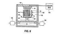
図4および図8を参照して、溶液71が入っていない状態の浸漬タンク52にカセット70を入れる別の実施形態を説明する。具体的には、浸漬タンク52の密閉端部58上に支持体95で保持された棚93の上に、カセット70を載置する。次に、シャワーヘッド101から浸漬タンク52内に溶液71を注入する。溶液71の供給装置103と流体連結されるシャワーヘッド101から、結合要素94を内部に混入(エントレインメント)させた溶液71が複数の流れとなって、流れ落ちる。浸漬タンク52に溶液71を注入するのと同時に、管路55を排出管として作用させ、浸漬タンク52から溶液71を排出するようにしてもよい。十分な時間にわたって、シャワーヘッド101から帯状になって流れ出る溶液71が、各基板の両面に沿って流れ落ちることにより、基板64の表面から汚染物質75が取り除かれる。本発明の別の実施形態において、管路55を閉じて、シャワーヘッド101から流れ落ちる溶液71を浸漬タンク52に貯留させて、基板64を溶液71内に沈めるようにしてもよい。この構成において、各管路55にポンプシステム106を連結させて、管路55を流れる流量を制御するようにしてもよい。また、柱部材95を用いて、棚(93)を位置105と位置107との間で移動可能としてもよい。このように、矢印109で示すように、溶液71と各基板64の両面との間に相反する方向への相対運動が生じる。 With reference to FIG. 4 and FIG. 8, another embodiment which puts the
懸濁液90は、たとえば、約1センチポイズ(cP)から約10,000cPの範囲の粘度を有する液体領域92を備える。液体領域69は、ニュートン流体でも非ニュートン流体でもよい。液体領域92として用いることができる物質の例としては、脱イオン水(DIW)、炭化水素、フッ化炭素、鉱油、アルコール等が挙げられる。懸濁液90が、さらに、イオン性溶媒あるいは非イオン性溶媒および他の化学添加物を含むものでもよい。共溶媒、pH調整剤、キレート剤、極性溶媒、界面活性剤、水酸化アンモニア、過酸化水素、フッ酸、水酸化テトラメチルアンモニウムや、高分子、粒子状物質、ポリペプチド等のレオロジー調整剤から選択される任意の組み合わせを、懸濁液90に化学添加物として添加することができる。 The
結合要素94は、上述した特性に加えて、結合要素94が表面98のごく近傍に存在する場合や接する場合でも表面98に付着することがないような物理的特性を備えるものでもよい。さらに、結合要素94が表面98に与える損傷や結合要素98と表面98との間の付着を最小限に抑えるような特性を結合要素94に与える。一実施形態において、結合要素94の硬さを、表面98の硬さよりも小さくする。さらに、結合要素94が表面98のごく近傍に存在する場合や接する場合でも表面98に結合要素94が付着されないことが望ましい。結合要素94は、結晶性固体でも非結晶性固体でもよい。非結晶性固体の例としては、脂肪族酸、カルボン酸、パラフィン、ワックス、高分子、ポリスチレン、ポリペプチド、その他粘弾性材料が挙げられる。懸濁液90中の結合要素94の濃度は、液体領域92における溶解度の限界を超えるものでなければならない。 In addition to the properties described above, the
脂肪族酸とは、基本的に、炭素原子が開鎖構造を形成する有機化合物からなる任意の酸を意味する。脂肪酸は、懸濁液90中に含まれる結合要素94として利用可能な脂肪族酸の一例である。利用可能な脂肪酸の例としては、ラウリン酸、パルミチン酸、ステアリン酸、オレイン酸、リノール酸、リノレン酸、アラキドン酸、ガドレイン酸、エルカ酸、酪酸、カプロン酸、カプリル酸、ミリスチン酸、マルガリン酸、ベヘン酸、リグノセリン酸、ミリストレイン酸、パルミトレイン酸、ネルボン酸、パリナリン酸、ティムノドン酸、ブラシジン酸、クルパノドン酸、リグノセリン酸、セロチン酸、並びに、これらの混合物が挙げられる。 An aliphatic acid basically means any acid composed of an organic compound in which carbon atoms form an open chain structure. The fatty acid is an example of an aliphatic acid that can be used as the binding
一実施形態において、結合要素94は、C−1からC−26あたりまでの範囲の種々の長さを持つ炭素鎖を有する脂肪酸の混合物である。カルボン酸とは、基本的には、一つあるいは複数のカルボキシル基(COOH)を有する任意の有機酸を意味する。結合要素94として利用可能なカルボン酸としては、C−1からC−100あたりまでの範囲の種々の長さを持つ炭素鎖の混合物が挙げられる。さらに、懸濁液90に対する不溶性を保持する限り、カルボン酸が、以下に限定されるものではないが、メチル、ビニル、アルキン、アミド、第1級アミン、第2級アミン、第3級アミン、アゾ、ニトリル、ニトロ、ニトロソ、ピリジル、カルボキシル、ペロキシ、アルデヒド、ケトン、第1級イミン、第2級イミン、エーテル、エステル、ハロゲン、イソシアネート、イソチオシアネート、フェニル、ベンジル、ホスホジエステル、スルフヒドリル等、他の官能性を有するものでもよい。 In one embodiment, binding
カルボン酸成分から形成される領域を有する懸濁液90の製造方法は、約3重量%から約50重量%の濃度範囲、望ましくは約4重量%から約20重量%の濃度範囲でカルボン酸の固体を脱イオン水(DIW)に混合して得られたゲルを液体領域69として準備する。得られた溶液にアンモニア水を加えた後、約55℃から85℃に加熱して、固体を溶液に溶解させてもよい。固体が溶解した後、洗浄溶液を冷却する。冷却する過程で、針状あるいは板状の固体成分が析出する。この方法で製造された懸濁液90は、たとえば、毎秒0.1のせん断率で、約1000cPの粘度を有し、せん断率を毎秒1000まで増大させると、粘度は約10cPまで減少する。すなわち、この懸濁液90は、非ニュートン流体である。また、アルコール等、水以外の極性溶媒あるいは非極性溶媒にカルボン酸(あるいはカルボン酸塩)を混合して得られた懸濁液を用いるようにしてもよい。 The process for preparing the
加水分解した化学物質から形成した結合要素94、あるいは、界面活性剤を加えた結合要素94を含む懸濁液90を製造するようにしてもよい。たとえば、懸濁液90全体への結合要素94の分散が容易になるように、液体領域92に分散剤成分を含有させてもよい。さらに、懸濁液90に塩基を加えて、化学量論的な量よりも少ないカルボン酸やステアリン酸のような物質から形成される結合要素94の混入(エントレインメント)を可能にするようにしてもよい。ここで、塩基としては、たとえば、アンモニア水を用いることができるが、任意の市販の塩基を用いてもよい。また、カルボキシレート基、リン酸基、硫酸基、ポリオール、エチレンオキシド等、懸濁液90に混和性のある部分を含有させることにより、結合要素94を形成する物質の表面機能に影響を与えることができる。このようにして、結合要素94を凝集させることなく、懸濁液90全体に結合要素94を分散することができる。すなわち、ほぼ均一な懸濁液90を形成できる。結合要素94が凝集してしまうと、表面98に結合して、および/あるいは、表面98から汚染物質96を除去する結合要素94が不足する。 A
図9を参照して、他の実施例を説明する。この実施例の懸濁液190には、液体領域192に混入(エントレインメント)される不混和成分111が、追加成分として含まれる。不混和成分は、気相物質でも、液相物質でも、固相物質でもよく、あるいは、それらの組み合わせでもよい。不混和成分111は、懸濁液190の液体領域192全体に分散された、複数の別々の気孔領域として存在する。懸濁液190に含まれる不混和成分の容量は、2%から99%である。気相不混和成分111は、たとえば、窒素N2、アルゴンAr、酸素O2、オゾンO3、過酸化水素H2O2、空気、水素H2、アンモニウムNH3、フッ化水素HF等の気体から形成されるものでもよい。Another embodiment will be described with reference to FIG. The
液相不混和成分111は、ペンタン、ヘキサン、ヘプタン、オクタン、ノナン、デカン等の低分子量アルカンや鉱油を含むものでもよい。あるいは、液相不混和成分111が、油溶性の表面改質剤を含むものでもよい。図4および図9を参照すればわかるように、懸濁液190は、懸濁液90と同様に機能して、汚染物質75を除去することができる。ここで、結合要素94は、結合要素94とほぼ同様のものであり、液体領域192は液体領域92とほぼ同様のものである。ただし、懸濁液190では、不混和成分111の存在により、結合要素194を、より容易に、汚染物質75に接触させる、あるいは、汚染物質75の近傍に接近させることができる。汚染物質75に近接あるいは接触する1つあるいは複数の領域が、汚染物質75と1つあるいは複数の不混和成分111との間に存在する。これと不混和成分111の表面張力とにより、液体領域192にかかる力に応じて、結合要素194に力(F)が加えられる。この力(F)により、結合要素194は、表面98すなわち汚染物質75に向かって移動する。結合要素194と汚染物質75との間は、結合要素94と汚染物質75とに関して上述したいずれの機構で、結合されるものでもよい。 The liquid phase
基板64上に懸濁液190を堆積させる前に、不混和成分111を懸濁液190に混入(エントレインメント)させるようにしてもよい。あるいは、表面98上に懸濁液190を堆積させているその場で(in situ)、不混和成分111を懸濁液190に混入(エントレインメント)させるようにしてもよいし、および/あるいは、表面98に懸濁液190を衝突させて、周辺環境に存在する空気等の気体を、泡を形成する等の方法で(混入)エントレインメントさせて、不混和成分111を生成させるものでもよい。たとえば、液体領域192内に溶解され、かつ、懸濁液190の圧力に対して相対的に周囲の圧力を下げると溶液から放出される気体から、不混和成分111を生成させてもよい。この方法の利点は、重力により結合要素194が表面98の方向に移動し、そこに留まっているため、不混和成分111の大部分を結合要素194の近傍で形成できることである。これにより、結合要素194が汚染物質75に結合する可能性が増大する。 Before the
二相懸濁液90と同様に、三相懸濁液190が、結合要素194と汚染物質との間の結合機構を調整・強化するために、追加成分を含有するようにしてもよい。たとえば、液状媒体のpHを調整して、固体成分および汚染物質のいずれか片方あるいは両方の表面電荷を相殺して、静電反発力を減少あるいは増大させるようにしてもよい。また、懸濁液190の温度サイクルにより、懸濁液190の特性を制御・変化させるようにしてもよい。たとえば、温度に比例して、あるいは、温度に反比例して展性が変化する物質から結合要素94を形成するようにしてもよい。結合要素94を汚染物質の形状にフィットさせた後、懸濁液の温度を変化させて、結合要素194の展性を減少させるようにしてもよい。さらに、懸濁液190の溶解度、すなわち、結合要素94の濃度が、温度に比例して、あるいは温度に反比例して、変化するものでもよい。 Similar to the two-
70℃以上に加熱した固体ステアリン酸を70℃以上に加熱したDIW(脱イオン水)に混合して、懸濁液190を作成してもよい。DIWに混合する固体ステアリン酸の重量は、約0.1%から10%である。このように混合することにより、DIW中にステアリン酸成分を十分に分散/乳化させることができる。混合物のpHを9以上に調整して、ステアリン酸成分を中和させるアンモニア水(NH4OH)等の塩基を0.25重量%から10重量%の範囲で加えることにより、このようなpH調整を行うことができる。このようにして形成された酸‐塩基混合物を20分間かくはんして、混合物を均一にする。酸−塩基混合物の温度を周辺温度と同じにして、脂肪酸塩を沈殿させて、結合要素194を形成する。沈殿形成される結合要素194の大きさは、0.5から5000マイクロメートルの範囲であることが望ましい。必要に応じて、酸‐塩基混合物をかくはんして、酸‐塩基混合物内に空気を混入(エントレインメント)させて、不混和成分111を形成するようにしてもよい。The
0.5から5000マイクロメートルの範囲の粒径に砕いたステアリン酸の粒状固体から懸濁液190を作成してもよい。DIWをかき混ぜながら、砕いた粒状のステアリン酸をDIWに加えて、酸‐DIW混合物を作成する。振とう、かくはん、回転等、周知の任意の手段でDIWをかき混ぜることができる。酸‐DIW混合物に含まれるステアリン酸の重量は約0.1%から10%である。塩基を加えて、酸‐DIW混合物のpHを約9に調整することにより、ステアリン酸が解離する。ここで用いられる塩基は、たとえば、0.5重量%から10重量%の濃度のアンモニア水(NH4OH)である。塩基を加えることにより、ステアリン酸成分が中和され、ステアリン酸のアンモニウム塩の粒子が形成される。酸‐DIW混合物をかき混ぜながら、酸‐DIW混合物にアンモニア水NH4OHを加えて、酸‐DIW混合物全体にステアリン酸の固体粒子を分散させる。ステアリン酸アンモニウムの固体粒子の粒度分布は、0.5から5000マイクロメートルの範囲である。
上述したように、イソプロピルアルコール(IPA)をかき混ぜながら、IPAに溶解させたステアリン酸‐パルミチン酸混合物から懸濁液190を作成してもよい。この場合、2重量%から20重量%の濃度範囲で、溶解脂肪酸が存在する。沸騰させることなくIPAを加熱すること、および/あるいは、アセトン、ベンゼン、あるいはその組み合わせ等の有機溶媒を加えることにより、脂肪酸の溶解度を増大させるようにしてもよい。溶解せずに残った固体をろ過や遠心分離技術で取り除き、固体を含まない溶液としてもよい。固体を含まない溶液を、水等の脂肪酸に対する非溶媒である液体と混合して、脂肪酸の固体を沈殿させるようにしてもよい。0.5から5000マイクロメートルの範囲の粒度で、沈殿させた脂肪酸を溶液に懸濁させる。上述したように、ステアリン酸成分をイオン化させてもよい。 As described above, the
図10を参照して、本発明の別の実施例に従う基板洗浄システム(SCS)400を説明する。基板洗浄システム400には、複数の浸漬タンク402、404、406が含まれる。各浸漬タンク402、404、406には、上述したいずれかの懸濁液、たとえば、懸濁液90や懸濁液190が入れられる。ピッカーシステムは、複数のピッカー408、410、412を備える。各ピッカー408、410、412を、連結して、軌道414に沿って往復動することにより、いずれかのピッカー408、410、412に把持された基板64をいずれかの浸漬タンク402、404、406内に挿入する。コンピュータ読み取り可能なメモリ418とデータ通信可能なプロセッサ416の制御下で、システム400が駆動される。プロセッサ416は、システム400を駆動制御して、浸漬タンク402、404、406内に基板64を挿入させる。また、プロセッサは、モーター420とデータ通信可能であり、軌道414に沿ってピッカー408、410、412を動かし、また、基板64を浸漬タンク402、404、406に対して出し入れさせる。さらに、プロセッサは、流体供給装置422、424、426とデータ通信可能であり、浸漬タンク408、410、412への流体の流入を制御する。また、プロセッサ416は、浸漬タンク408、410、412とデータ通信可能であり、浸漬タンクを駆動制御し、たとえば、浸漬タンク408、410、412から流体を排出させる。 With reference to FIG. 10, a substrate cleaning system (SCS) 400 according to another embodiment of the present invention will be described. The
図10および図11を参照して、複数のピッカー408、410、412の1つであるピッカー408の作動時の様子を説明する。ピッカー408を用いて、複数の浸漬タンク402、404、406の1つである浸漬タンク402内に基板64を入れる。浸漬タンク402内で、基板64は、支持体428上に保持される。次に、浸漬タンク402に溶液71を満たす。プロセッサ416の制御下で、溶液71を浸漬タンク402内に注入する。プロセッサ416が、流体供給装置422の(図示しない)ポンプを起動させると、溶液71が、流体供給装置422から管路430を通って、所望の浸漬タンク402、404、406内に注入される。浸漬タンク402、404、406は、浸漬タンク内に注入される溶液の流量を制御するために、それぞれ、プロセッサ416とデータ通信可能でプロセッサ416の制御下で起動されるバルブ432、434、436を備える。バルブ432の起動により、選択的に、流体供給装置422、424、426から浸漬タンク402内に流体を流入させたり、流れを遮断したりする。同様に、バルブ434の起動により、選択的に、流体供給装置422、424、426から浸漬タンク404内に流体を流入させたり、流れを遮断したりする。バルブ436の起動により、選択的に、流体供給装置422、424、426から浸漬タンク406内に流体を流入させたり、流れを遮断したりする。また、プロセッサ416とデータ通信可能でプロセッサ416により制御されるポンプ438、440、442を用いて、浸漬タンク402、404、406からの流体の排出を制御する。具体的には、ポンプ438が浸漬タンク402からの排出を促進・遮断し、ポンプ440が浸漬タンク404からの排出を促進・遮断し、ポンプ442が浸漬タンク406からの排出を促進・遮断する。 With reference to FIG. 10 and FIG. 11, the mode at the time of the action | operation of the
図示した作動モードにおいて、流出口446から溶液71を浸漬タンク402内に注入して、浸漬タンク402を満たす。この工程は、浸漬タンク402に基板62を入れる前に行っても、入れた後に行ってもよいが、一般的には、溶液71を注入する前に、浸漬タンク402内に基板64を入れる。支持体428に基板64を保持させた後、プロセッサ416の制御下で、浸漬タンク402内に溶液71を注入する。溶液71を流出口446から注入しつつ、プロセッサ416がポンプ438を駆動して、浸漬タンク402から溶液71を排出させる。このようにして、基板64が溶液71の連続的な流れにさらされる。各浸漬タンク402、404、406を同時に用いて、基板64を溶液71の連続的な流れにさらすようにしてもよい。バルブ432、434、436を起動することにより、供給装置422、424、426のいずれか1つから浸漬タンク420、404、406に溶液71を流入させる。別の例として、供給装置422、424、426のいずれか1つから供給されるDIWを1つあるいは複数の浸漬タンク402、404、406に入れておくようにしてもよい。溶液71に基板64をさらした後、基板564をDIWにさらして洗う。この場合、浸漬タンク420、404、406のいずれか1つにDIWを満たした後、その中に基板64を入れるようにしてもよい。逆に、基板64を浸漬タンク420、404、406のいずれか1つに入れた後、DIWをその浸漬タンクに注入するようにしてもよい。さらに別の例として、浸漬タンク402、404、406のいずれか1つに懸濁液90を満たし、浸漬タンク402、404、406の別の1つに懸濁液190を満たし、浸漬タンク402、404、406の残った1つにDIWを満たすようにしてもよい。この構成では、基板64を懸濁液90と懸濁液190の両方にさらした後、DIWにさらして洗う。同一の浸漬タンク402を用いて、懸濁液90、懸濁液190、DIWの順に基板64をさらすような構成も可能である。必要に応じて、基板64を入れた後、浸漬タンク402、404、406を閉じるようにしてもよい。図示した例では、ヘリウム等のパージガス供給装置454に接続される管路52を備えるカバー450で、浸漬タンク406を閉じる。このようにして浸漬タンク406を環境制御することにより、基板84の予定外の乾燥を防ぐ、あるいは、少なくとも抑制する。Oリングを用いて、カバー450と浸漬タンク406との間を密閉するようにしてもよい。 In the illustrated mode of operation,
図10および図12を参照して、浸漬タンク402、404、406の代わりに利用可能な浸漬タンク502を説明する。浸漬タンク502は、Oリング505を有する蓋部503を備え、浸漬タンク502の本体507を流体密封する。具体的には、浸漬タンクは、複数の管路540、542、544、546、547、548、550、552を備える。管路540および管路548は、選択的に、イソプロピルアルコール(IPA)の供給装置とDIWの供給装置とに流体連結され、管路546および管路552は、選択的に、洗浄液の供給装置とDIWの供給装置とに流体連結される。具体的には、管路540は、それぞれ、バルブ558およびバルブ560を介して、選択的にIPA供給装置554とDIW供給装置556とに流体連結される。また、管路548は、それぞれ、バルブ566およびバルブ568を介して、選択的にIPA供給装置562とDIW供給装置564とに流体連結される。管路542および管路550は、それぞれ排液管570および排液管572に流体連結される。管路546は、それぞれバルブ580およびバルブ582を介して、選択的に洗浄溶液71の供給装置574とDIWの供給装置576に流体連結される。管路547は、バルブ551を介して、選択的に排液管549に流体連結される。また、管路552は、それぞれバルブ588およびバルブ590を介して、選択的に洗浄溶液71の供給装置584とDIWの供給装置586に流体連結される。 With reference to FIGS. 10 and 12, a
作動時には、溶液71が入っていない状態で、浸漬タンク502に基板64を入れる。プロセッサ416の制御下で、バルブ580およびバルブ588のいずれか1つあるいは両方を起動させて、それぞれの管路546および552を介して、浸漬タンク502に溶液を流入させる。この結果、重力g→と反対の方向への溶液71の流れ600および602が形成され、それぞれ基板64の両面65および67に隣接して流れる。一方、浸漬タンク502から流出する溶液は、管路542および550を通って、それぞれ排液管570および572に排出される。十分な量の溶液71にさらした後、各表面65および67をIPAおよび/あるいはDIWのいずれか1つあるいは両方にさらして洗う。そのために、バルブ580および588を遮断し、バルブ582および590を起動する。これにより、基板64は、供給装置576および586から流入するDIWにさらされる。DIWは、排液管570および572に排出される。あるいは、バルブ551、560および568を起動することにより、重力g→方向へのDIWの流れ610および612が形成され、排液管549に排出される。この操作は、非真空条件で行われる。基板64をDIWに完全に沈めた後、ポンプ570を駆動して、DIWを排出させる。同様に、バルブ558および566を起動して、供給装置から流入するIPAで洗ってもよい。In operation, the
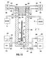
図12および図13を参照して、本発明の別の実施例に従い、浸漬タンク502の代わりに利用可能な浸漬タンク602を説明する。浸漬タンク602は、本体607と、管路642、644、646、647、650、652と、排液管649、670、672と、供給装置674、676、684、686と、バルブ680、682、688、649とを備え、これらは、それぞれ、本体507と、管路542、544、546、547、550、552と、排液管570、572と、供給装置574、576、584、586と、バルブ580、582、588、549と同様の機能を果たす。さらに、浸漬タンク602は、本体607の内部に、2つの管路691および692を備え、この管路を通って、供給装置654および662からそれぞれIPAが浸漬タンクに流入する。具体的には、バルブ658により、選択的にIPAが供給装置654から浸漬タンク602に流入し、バルブ666により、選択的にIPAが供給装置662から浸漬タンク602に流入する。また、バルブ660により、選択的にDIWが供給装置656から浸漬タンク602に流入し、バルブ668により、選択的にDIWが供給装置664から浸漬タンク602に流入する。さらに、基板64を保持する支持体693がモーター694に接続され、基板64と管路647との間の距離を変更することができる。蓋部603は、2組のOリング605および606を備える。Oリング605は、Oリング605と同様に作用する。一方、Oリング606は、管路540および548と管路542および550との間に設置される蓋部603のストッパー部695の端部に位置する。この構成では、管路691,692、640および648は、バルブ551を遮断して排液管549に流体が流れ込まないようにした場合に、管路546および552から流出する流体の流れから分離される。すなわち、管路642および650と管路691、692、640および648との間が流体密封される。 With reference to FIGS. 12 and 13, a
図13に示す作動時には、溶液71が入っていない状態で、浸漬タンク602に基板64を入れる。プロセッサ416の制御下で、バルブ680およびバルブ688のいずれか1つあるいは両方を起動させて、それぞれの管路646および652を介して、浸漬タンク602に溶液を流入させる。ここで、バルブ551が遮断されているため、溶液71は排液管549に流出しない。この結果、重力g→と反対の方向への溶液71の流れ700および702が形成され、それぞれ基板64の両面65および67に隣接して流れる。一方、浸漬タンク602から流出する溶液は、管路642および650を通って、それぞれ排液管670および672に排出される。At the time of the operation shown in FIG. 13, the
図13および図14に示すように、十分な量の溶液71にさらした後、各表面65および67をIPAおよび/あるいはDIWのいずれか1つあるいは両方にさらして洗う。具体的には、蓋部601を取り外して、管路691、692、540および548を管路542および550に流体連結させる。バルブ658および666を起動することにより、重力g→方向へのIPAの流れが形成される。この結果、浸漬タンク602内のメニスカス700で、溶液71がIPAおよび空気と接する。管路691および692の両方からIPAが流入する際に、モーター694が駆動し、支持体693を動かし、基板64を浸漬タンク602から上に持ち上げる。このように浸漬タンクから取り出される際に、基板64から溶液71が除去される。As shown in FIGS. 13 and 14, after exposure to a sufficient amount of
以上、本発明をいくつかの実施形態に沿って説明してきた。本明細書並びに図面を参照した当業者には自明であるが、本発明をさまざまに変形したり、追加したり、置き換えたり、等価のものにしたりすることが可能である。したがって、本発明には、本発明の要旨の範囲内で、さまざまな変形・追加・置き換え・等価のものがすべて含まれる。以下に示す請求項において、明示されていない限り、各構成要素および/あるいは工程は特定の操作の順番を示すものではない。 The present invention has been described according to some embodiments. Although it will be apparent to those skilled in the art with reference to the specification and drawings, the present invention can be variously modified, added, replaced, and made equivalent. Therefore, the present invention includes all various modifications, additions, replacements, and equivalents within the scope of the present invention. In the claims that follow, each component and / or step does not indicate a specific order of operation, unless explicitly stated otherwise.
Claims (25)
Translated fromJapanese複数の基板が載置されたカセットを、結合要素を内部に混入させた溶液にさらすことにより、前記複数の基板と前記溶液との間に同時に相対運動を生じさせ、前記相対運動により十分な抗力が前記結合要素の一部に加えられる結果、前記溶液内で前記結合要素の一部に動きが生じて、所定量の抗力が前記汚染物質に加えられて、前記基板に対して前記汚染物質を動かす工程を備える、方法。A method of cleaning a plurality of substrates having surfaces on both sides and having a contaminant attached to at least one surface,
By exposing a cassette on which a plurality of substrates are placed to a solution in which a coupling element is mixed, a relative movement is caused between the plurality of substrates and the solution at the same time. Is added to a portion of the coupling element, resulting in movement of a portion of the coupling element in the solution, and a predetermined amount of drag is applied to the contaminant to cause the contaminant to move against the substrate. A method comprising the step of moving.
前記同時に相対運動を生じさせる工程が、前記溶液を所定の体積までタンクに満たした後、前記カセットを前記体積内に挿入することにより、前記複数の基板の各々を前記体積内に沈める工程を含む、方法。The method of claim 1, comprising:
The step of causing the relative movement simultaneously includes the step of submerging each of the plurality of substrates in the volume by inserting the cassette into the volume after filling the tank with the solution to a predetermined volume. ,Method.
前記同時に相対運動を生じさせる工程が、
前記溶液を所定の体積までタンクに満たした後、前記カセットを前記体積内に挿入することにより、前記複数の基板の表面と前記溶液との間に第1の方向に沿った相対運動を生じさせる工程と、
前記カセットを前記体積から取り出すことにより、前記表面の間に前記第1の方向とは逆の第2の方向に沿った相対運動を生じさせる工程とを含む、方法。The method of claim 1, comprising:
Producing the relative motion simultaneously,
After filling the tank with the solution to a predetermined volume, the cassette is inserted into the volume, thereby causing a relative movement along a first direction between the surfaces of the plurality of substrates and the solution. Process,
Removing the cassette from the volume to cause relative movement between the surfaces along a second direction opposite to the first direction.
前記同時に相対運動を生じさせる工程が、前記カセットをタンク内に入れた後、前記タンク内に前記溶液を十分な体積まで注入することにより、前記複数の基板の各々を前記体積内に沈める工程を含む、方法。The method of claim 1, comprising:
The step of simultaneously causing relative movement includes the step of sinking each of the plurality of substrates into the volume by injecting the solution into the tank to a sufficient volume after the cassette is placed in the tank. Including.
前記同時に相対運動を生じさせる工程が、
前記カセットをタンク内に入れた後、十分な量の前記溶液を、前記複数の基板の各々を沈めるのに十分な所定の体積になるように、前記タンクに注入することにより、前記溶液と前記複数の基板の表面との間に、第1の方向に沿った相対運動を生じさせる工程と、
前記カセットを前記体積から取り出すことにより、前記表面の間に前記第1の方向とは逆の第2の方向に沿った相対運動を生じさせる工程とを含む、方法。The method of claim 1, comprising:
Producing the relative motion simultaneously,
After the cassette is placed in the tank, a sufficient amount of the solution is poured into the tank so as to have a predetermined volume sufficient to sink each of the plurality of substrates. Producing a relative movement along a first direction between the surfaces of the plurality of substrates;
Removing the cassette from the volume to cause relative movement between the surfaces along a second direction opposite to the first direction.
結合要素を内部に混入させた溶液と前記基板との間に、前記両側の表面のうちの1つの表面の法線を横切る方向に沿った相対運動を生じさせることにより、2つの流れのうちの一方の流れが前記両側の表面のうちの1つの表面に隣接し、また、他方の流れが1つの表面とは異なる別の表面に隣接するように、分離した2つの流れを発生させ、前記相対運動により結合要素の一部に十分な抗力が加えられる結果、前記溶液内部で前記結合要素の一部に動きが生じて、所定量の抗力が前記汚染物質に加えられて、前記基板に対して前記汚染物質を動かす工程を備える、方法。A method of cleaning a substrate having surfaces on both sides and having a contaminant attached to at least one surface,
By causing a relative movement between the solution entrained therein with the substrate and the substrate along a direction normal to the surface of one of the two surfaces, one of the two flows Two separate flows are generated such that one flow is adjacent to one of the surfaces on both sides and the other flow is adjacent to another surface different from one surface, and the relative Movement results in sufficient drag being applied to a portion of the coupling element, resulting in movement of the portion of the coupling element within the solution, so that a predetermined amount of drag is applied to the contaminant to the substrate. Moving the contaminant.
前記分離した流れの各々が、同一の方向に流れる、方法。The method of claim 6, comprising:
The method wherein each of the separated streams flows in the same direction.
前記分離した2つの流れが、同時に前記基板の周囲に流れる、方法。The method of claim 6, comprising:
The method wherein the two separated streams flow simultaneously around the substrate.
前記分離した2つの流れの方向を逆転させる工程を備える、方法。The method of claim 6, further comprising:
Reversing the direction of the two separated flows.
前記基板を容器に入れる工程を備え、 前記相対運動を生じさせる工程が、前記容器の第1端部から前記基板に向かう前記溶液の2つの流れを形成し、前記第1端部の反対側に位置する前記容器の第2端部から前記溶液の2つの流れを排出する工程を含む、方法。The method of claim 6, further comprising:
Placing the substrate into a container, wherein the step of creating relative motion forms two flows of the solution from the first end of the container toward the substrate, on the opposite side of the first end. Draining the two streams of the solution from the second end of the container located.
重力方向を横切って伸長する法線を有する容器に前記基板を入れる工程を備え、
前記相対運動を生じさせる工程が、前記基板に向かう前記溶液の流れを形成する工程を含み、前記分離した2つの流れは前記重力方向とほぼ平行な方向に流れる、方法。The method of claim 6, further comprising:
Placing the substrate in a container having a normal extending across the direction of gravity;
The method of causing the relative motion includes forming a flow of the solution toward the substrate, wherein the two separated flows flow in a direction substantially parallel to the direction of gravity.
前記相対運動を生じさせる工程が、前記結合要素の一部に十分な運動量を加えることにより、前記結合要素の一部を前記汚染物質に接触させて、前記基板に対して前記汚染物質を動かす工程を含む、方法。The method of claim 6, comprising:
Causing the relative motion to move the contaminant relative to the substrate by applying a sufficient momentum to the portion of the coupling element to bring the portion of the coupling element into contact with the contaminant; Including the method.
前記分離した2つの流れが泡から形成されるように前記溶液から泡を形成する工程を含む、方法。The method of claim 6, further comprising:
Forming a foam from the solution such that the two separated streams are formed from the foam.
前記溶液から泡を形成することにより、実質的に前記泡から形成される前記分離した2つの流れを発生させる工程と、
前記分離した2つの流れを止めた後、前記基板を溶液にさらして前記泡を取り除き、前記基板を減圧して前記溶液を取り除く工程と、を備える方法。The method of claim 6, further comprising:
Generating the separated two streams substantially formed from the bubbles by forming bubbles from the solution; and
After stopping the two separated flows, exposing the substrate to a solution to remove the bubbles and depressurizing the substrate to remove the solution.
結合要素を内部に混入させた溶液の複数の流れを前記両側表面に隣接するように発生させて、前記複数の流れの各々が十分な抗力を前記結合要素に加える結果として、前記溶液内部で前記結合要素の一部に動きが生じ、十分な大きさである所定の抗力が前記汚染物質に加えられて、前記基板に対して前記汚染物質を動かす工程を備える、方法。A method of cleaning a substrate having both surfaces with contaminants attached thereto,
As a result of generating a plurality of flows of a solution having a binding element incorporated therein adjacent to the opposite side surfaces, each of the plurality of streams exerts sufficient drag on the binding element, and within the solution A method comprising causing movement of a portion of a coupling element and applying a predetermined drag that is sufficiently large to the contaminant to move the contaminant relative to the substrate.
前記基板を容器に入れる工程を備え、
前記複数の流れを発生させる工程が、
前記容器の第1端部から前記基板に向かう前記溶液の2つの流れを形成し、前記第1端部の反対側に位置する前記容器の第2端部から前記溶液の2つの流れを排出する工程を含む、方法。The method of claim 15, further comprising:
Comprising the step of placing the substrate in a container;
Generating the plurality of flows comprises:
Two flows of the solution are formed from the first end of the container toward the substrate, and the two flows of the solution are discharged from the second end of the container located on the opposite side of the first end. A method comprising the steps.
重力方向を横切って伸長する法線を有する容器に前記基板を入れる工程を備え、
前記複数の流れを発生させる工程が、前記基板に向かう前記溶液の流れを形成する工程とを含み、前記分離した2つの流れは前記重力方向とほぼ平行な方向に流れる、方法。The method of claim 15, further comprising:
Placing the substrate in a container having a normal extending across the direction of gravity;
Generating the plurality of flows includes forming a flow of the solution toward the substrate, wherein the two separated flows flow in a direction substantially parallel to the direction of gravity.
前記複数の流れを発生させる工程が、前記結合要素の一部に十分な運動量を加えることにより、前記結合要素の一部を前記汚染物質に接触させて、前記基板に対して前記汚染物質を動かす工程を含む、方法。The method of claim 15, comprising:
The step of generating the plurality of flows moves the contaminant relative to the substrate by applying a sufficient momentum to the portion of the coupling element to bring the portion of the coupling element into contact with the contaminant. A method comprising the steps.
前記分離した2つの流れが泡から形成されるように前記溶液から泡を形成する工程を含む、方法。The method of claim 15, further comprising:
Forming a foam from the solution such that the two separated streams are formed from the foam.
前記溶液から泡を形成することにより、実質的に前記泡から形成される前記複数の流れを発生させ、前記分離した2つの流れを止めた後、前記基板を溶液にさらして前記泡を取り除き、前記基板を減圧して前記溶液を取り除く工程を含む、方法。The method of claim 15, further comprising:
Generating the plurality of flows substantially formed from the bubbles by forming bubbles from the solution, stopping the two separated flows, and then exposing the substrate to the solution to remove the bubbles; And depressurizing the substrate to remove the solution.
溶液取扱サブシステムと、
前記基板を保持する搬送サブシステムと、
前記溶液供給サブシステムと流体連結される容器を備えるハウジング部と、
前記溶液供給サブシステムと、前記搬送サブシステムと、前記ハウジング部とのデータ通信が可能なプロセッサと、
前記プロセッサにより実行されるコンピュータ読み取り可能な命令を格納し、前記プロセッサとデータ通信が可能なメモリと、
を備え、
前記コンピュータ読み取り可能な命令は、
前記搬送サブシステムを制御して前記容器内に前記基板を入れる第1コード群と、
前記溶液取扱サブシステムを制御して結合要素を内部に混入させた溶液の複数の流れを前記基板の前記両側表面に隣接するように発生させて、前記溶液供給システムにより前記複数の流れの各々が十分な抗力を前記結合要素の一部に加える結果として、前記溶液内部で前記結合要素の一部に動きが生じ、十分な大きさである所定の抗力が前記汚染物質に加えられて、前記基板に対して前記汚染物質を動かす第2コード群とを含むコンピュータ読み取り可能な命令を記憶するメモリと、
を備えるシステム。A system comprising a processing area for removing contaminants from both sides of a substrate,
A solution handling subsystem;
A transport subsystem for holding the substrate;
A housing portion comprising a container fluidly connected to the solution supply subsystem;
A processor capable of data communication with the solution supply subsystem, the transport subsystem, and the housing;
A computer readable instruction executed by the processor; and a memory capable of data communication with the processor;
With
The computer readable instructions are:
A first code group for controlling the transport subsystem to place the substrate in the container;
Controlling the solution handling subsystem to generate a plurality of flow of solutions having coupling elements incorporated therein adjacent to the opposite side surfaces of the substrate so that each of the plurality of flows is caused by the solution supply system. As a result of applying sufficient drag to the part of the coupling element, movement of the part of the coupling element occurs within the solution, and a predetermined drag that is sufficiently large is applied to the contaminant, so that the substrate A memory for storing computer readable instructions including a second code group for moving said contaminant with respect to
A system comprising:
前記コンピュータ読み取り可能な命令が、さらに、
前記溶液取扱システムを制御して、前記複数の流れを止めて、前記容器を前記溶液で満たす第1サブルーチンと、
前記基板搬送サブシステムを制御して、前記容器から前記基板を取り出すことによって、前記両側表面と前記複数の流れとの間の相対運動と実質的に同一の方向に沿った相対運動を、前記溶液と前記両側表面との間に生じさせる第2サブルーチンとを含む、システム。The system of claim 22, wherein
The computer readable instructions further include:
A first subroutine for controlling the solution handling system to stop the plurality of flows and fill the container with the solution;
By controlling the substrate transport subsystem to remove the substrate from the container, the relative movement along substantially the same direction as the relative movement between the two side surfaces and the plurality of flows is reduced by the solution. And a second subroutine that occurs between the two side surfaces.
前記コンピュータ読み取り可能な命令が、さらに、
前記溶液取扱システムを制御して、前記容器を前記溶液で満たして溶液入り容器とする第1サブルーチンと、
前記基板搬送サブシステムを制御して、前記基板を前記溶液入り容器に入れることによって、前記両側表面と前記複数の流れとの間の相対運動と反対方向に沿った相対運動を、前記溶液と前記両側表面との間に生じさせる第2サブルーチンとを含む、システム。The system of claim 22, wherein
The computer readable instructions further include:
A first subroutine for controlling the solution handling system to fill the container with the solution into a solution-filled container;
By controlling the substrate transport subsystem to place the substrate into the solution-containing container, relative movement along the opposite direction to the relative movement between the side surfaces and the plurality of flows is caused to move between the solution and the solution. And a second subroutine that occurs between both surfaces.
前記複数の流れは、第1方向に沿った流れであり、
前記コンピュータ読み取り可能な命令が、さらに、前記容器を所定量の前記溶液で満たし、前記複数の流れを止めた後、前記搬送サブシステムを制御して、前記所定量の溶液内で前記基板を前記第1方向と前記第1方向とは反対の第2方向との間で往復動させるサブルーチンを含む、システム。The system of claim 22, wherein
The plurality of flows are flows along a first direction;
The computer-readable instructions further control the transfer subsystem after filling the container with a predetermined amount of the solution and stopping the plurality of flows to place the substrate in the predetermined amount of the solution. A system comprising a subroutine for reciprocating between a first direction and a second direction opposite to the first direction.
前記複数の流れが第1方向に沿った流れであり、
前記コンピュータ読み取り可能な命令が、さらに、前記搬送サブシステムを制御して、前記基板を前記第1方向と前記第1方向とは反対の第2方向との間で往復動させるサブルーチンを含む、システム。The system of claim 22, wherein
The plurality of flows are flows along a first direction;
The computer readable instructions further includes a subroutine for controlling the transport subsystem to reciprocate the substrate between the first direction and a second direction opposite the first direction. .
Applications Claiming Priority (2)
| Application Number | Priority Date | Filing Date | Title |
|---|---|---|---|
| US11/743,283US8388762B2 (en) | 2007-05-02 | 2007-05-02 | Substrate cleaning technique employing multi-phase solution |
| PCT/US2008/004488WO2008136895A1 (en) | 2007-05-02 | 2008-04-04 | Substrate cleaning techniques employing multi-phase solution |
Publications (2)
| Publication Number | Publication Date |
|---|---|
| JP2010526436Atrue JP2010526436A (en) | 2010-07-29 |
| JP2010526436A5 JP2010526436A5 (en) | 2011-05-19 |
Family
ID=39938699
Family Applications (1)
| Application Number | Title | Priority Date | Filing Date |
|---|---|---|---|
| JP2010506194AWithdrawnJP2010526436A (en) | 2007-05-02 | 2008-04-04 | Substrate cleaning technology using multiphase solution |
Country Status (6)
| Country | Link |
|---|---|
| US (2) | US8388762B2 (en) |
| JP (1) | JP2010526436A (en) |
| KR (1) | KR20100017560A (en) |
| CN (1) | CN101675509B (en) |
| TW (1) | TWI445848B (en) |
| WO (1) | WO2008136895A1 (en) |
Families Citing this family (14)
| Publication number | Priority date | Publication date | Assignee | Title |
|---|---|---|---|---|
| US8043441B2 (en) | 2005-06-15 | 2011-10-25 | Lam Research Corporation | Method and apparatus for cleaning a substrate using non-Newtonian fluids |
| US8226775B2 (en) | 2007-12-14 | 2012-07-24 | Lam Research Corporation | Methods for particle removal by single-phase and two-phase media |
| US8828145B2 (en)* | 2009-03-10 | 2014-09-09 | Lam Research Corporation | Method of particle contaminant removal |
| FR2966972B1 (en) | 2010-10-27 | 2013-07-19 | Areva T & D Sas | METALLIC ENVELOPE ELECTRICAL EQUIPMENT COMPRISING AT LEAST ONE PARE-EFFLUVE HOOD PROVIDING CONVICTIVE EXCHANGES |
| US9127241B2 (en) | 2011-09-21 | 2015-09-08 | Ecolab Usa Inc. | Development of extensional viscosity for reduced atomization for diluted concentrate sprayer applications |
| US9293305B2 (en) | 2011-10-31 | 2016-03-22 | Lam Research Corporation | Mixed acid cleaning assemblies |
| US9728428B2 (en) | 2013-07-01 | 2017-08-08 | Applied Materials, Inc. | Single use rinse in a linear Marangoni drier |
| US20150090299A1 (en)* | 2013-09-27 | 2015-04-02 | Applied Materials, Inc. | Processes and apparatus for cleaning, rinsing, and drying substrates |
| US9818633B2 (en) | 2014-10-17 | 2017-11-14 | Lam Research Corporation | Equipment front end module for transferring wafers and method of transferring wafers |
| US12018374B2 (en)* | 2019-03-08 | 2024-06-25 | Dsgi Technologies, Inc. | System and method of low temperature thin film deposition and in-situ annealing |
| WO2021144982A1 (en)* | 2020-01-17 | 2021-07-22 | 東邦化成株式会社 | Liquid chemical processing device |
| US11682567B2 (en) | 2020-06-30 | 2023-06-20 | Applied Materials, Inc. | Cleaning system with in-line SPM processing |
| US12023779B2 (en) | 2021-07-14 | 2024-07-02 | Applied Materials, Inc. | Post-chemical mechanical polishing brush cleaning box |
| CN116580778B (en)* | 2023-04-28 | 2025-03-28 | 西南石油大学 | Establishment of a steady-state foam transport model coupled with the drag force of CO2 bubble liquid film |
Citations (2)
| Publication number | Priority date | Publication date | Assignee | Title |
|---|---|---|---|---|
| US20060128590A1 (en)* | 2003-06-27 | 2006-06-15 | Lam Research Corporation | Method for removing contamination from a substrate and for making a cleaning solution |
| JP2006179765A (en)* | 2004-12-24 | 2006-07-06 | Dainippon Screen Mfg Co Ltd | Substrate processing apparatus and particle removing method |
Family Cites Families (86)
| Publication number | Priority date | Publication date | Assignee | Title |
|---|---|---|---|---|
| US3617095A (en)* | 1967-10-18 | 1971-11-02 | Petrolite Corp | Method of transporting bulk solids |
| US3978176A (en)* | 1972-09-05 | 1976-08-31 | Minnesota Mining And Manufacturing Company | Sparger |
| JPS5924849A (en) | 1982-08-02 | 1984-02-08 | Hitachi Ltd | How to clean a photo mask |
| US4838289A (en)* | 1982-08-03 | 1989-06-13 | Texas Instruments Incorporated | Apparatus and method for edge cleaning |
| JPS62119543A (en) | 1985-11-20 | 1987-05-30 | Mitsubishi Electric Corp | semiconductor manufacturing equipment |
| US4902350A (en)* | 1987-09-09 | 1990-02-20 | Robert F. Orr | Method for rinsing, cleaning and drying silicon wafers |
| US5048549A (en)* | 1988-03-02 | 1991-09-17 | General Dynamics Corp., Air Defense Systems Div. | Apparatus for cleaning and/or fluxing circuit card assemblies |
| NL8900480A (en)* | 1989-02-27 | 1990-09-17 | Philips Nv | METHOD AND APPARATUS FOR DRYING SUBSTRATES AFTER TREATMENT IN A LIQUID |
| US5271774A (en)* | 1990-03-01 | 1993-12-21 | U.S. Philips Corporation | Method for removing in a centrifuge a liquid from a surface of a substrate |
| DE4038587A1 (en) | 1990-12-04 | 1992-06-11 | Hamatech Halbleiter Maschinenb | Conveyor system for flat substrates - transports by liq. film flow along surface e.g. for handling at various work-stations |
| JPH0515857A (en) | 1991-07-15 | 1993-01-26 | Sharp Corp | Washing device |
| JP2639771B2 (en)* | 1991-11-14 | 1997-08-13 | 大日本スクリーン製造株式会社 | Substrate cleaning / drying processing method and processing apparatus |
| JPH06459A (en)* | 1992-06-19 | 1994-01-11 | T H I Syst Kk | Method for cleaning and drying and apparatus thereof |
| US5464480A (en)* | 1993-07-16 | 1995-11-07 | Legacy Systems, Inc. | Process and apparatus for the treatment of semiconductor wafers in a fluid |
| US5518542A (en)* | 1993-11-05 | 1996-05-21 | Tokyo Electron Limited | Double-sided substrate cleaning apparatus |
| US5938504A (en)* | 1993-11-16 | 1999-08-17 | Applied Materials, Inc. | Substrate polishing apparatus |
| DE4413077C2 (en)* | 1994-04-15 | 1997-02-06 | Steag Micro Tech Gmbh | Method and device for chemical treatment of substrates |
| US6081650A (en)* | 1994-06-30 | 2000-06-27 | Thomson Licensing S.A. | Transport processor interface and video recorder/playback apparatus in a field structured datastream suitable for conveying television information |
| US5705223A (en)* | 1994-07-26 | 1998-01-06 | International Business Machine Corp. | Method and apparatus for coating a semiconductor wafer |
| US5660642A (en)* | 1995-05-26 | 1997-08-26 | The Regents Of The University Of California | Moving zone Marangoni drying of wet objects using naturally evaporated solvent vapor |
| KR970077292A (en) | 1996-05-02 | 1997-12-12 | 김광호 | Etching device for semiconductor device manufacturing |
| DE19622015A1 (en)* | 1996-05-31 | 1997-12-04 | Siemens Ag | Process for etching destruction zones on a semiconductor substrate edge and etching system |
| KR19980016831A (en)* | 1996-08-29 | 1998-06-05 | 김광호 | Semiconductor wafer cleaning equipment |
| TW357406B (en)* | 1996-10-07 | 1999-05-01 | Tokyo Electron Ltd | Method and apparatus for cleaning and drying a substrate |
| JPH10144650A (en)* | 1996-11-11 | 1998-05-29 | Mitsubishi Electric Corp | Semiconductor material cleaning equipment |
| US5858283A (en)* | 1996-11-18 | 1999-01-12 | Burris; William Alan | Sparger |
| US5900191A (en)* | 1997-01-14 | 1999-05-04 | Stable Air, Inc. | Foam producing apparatus and method |
| US6068002A (en)* | 1997-04-02 | 2000-05-30 | Tokyo Electron Limited | Cleaning and drying apparatus, wafer processing system and wafer processing method |
| US6701941B1 (en)* | 1997-05-09 | 2004-03-09 | Semitool, Inc. | Method for treating the surface of a workpiece |
| JPH10321572A (en)* | 1997-05-15 | 1998-12-04 | Toshiba Corp | Semiconductor wafer double-side cleaning apparatus and semiconductor wafer polishing method |
| US6152805A (en)* | 1997-07-17 | 2000-11-28 | Canon Kabushiki Kaisha | Polishing machine |
| US6398975B1 (en)* | 1997-09-24 | 2002-06-04 | Interuniversitair Microelektronica Centrum (Imec) | Method and apparatus for localized liquid treatment of the surface of a substrate |
| US6491764B2 (en)* | 1997-09-24 | 2002-12-10 | Interuniversitair Microelektronics Centrum (Imec) | Method and apparatus for removing a liquid from a surface of a rotating substrate |
| EP0905746A1 (en) | 1997-09-24 | 1999-03-31 | Interuniversitair Micro-Elektronica Centrum Vzw | Method of removing a liquid from a surface of a rotating substrate |
| DE69828592T8 (en) | 1997-09-24 | 2006-06-08 | Interuniversitair Micro-Elektronica Centrum Vzw | METHOD FOR REMOVING A LIQUID FROM A SURFACE OF A SUBSTRATE |
| JPH11334874A (en) | 1998-05-25 | 1999-12-07 | Speedfam-Ipec Co Ltd | Transport device |
| JPH11350169A (en) | 1998-06-10 | 1999-12-21 | Chemitoronics Co | Wet etching apparatus and wet etching method |
| JP2000141215A (en)* | 1998-11-05 | 2000-05-23 | Sony Corp | Flattening grinding device and its method |
| US6090217A (en)* | 1998-12-09 | 2000-07-18 | Kittle; Paul A. | Surface treatment of semiconductor substrates |
| JP2000260739A (en)* | 1999-03-11 | 2000-09-22 | Kokusai Electric Co Ltd | Substrate processing apparatus and substrate processing method |
| US6290780B1 (en)* | 1999-03-19 | 2001-09-18 | Lam Research Corporation | Method and apparatus for processing a wafer |
| JP2002540623A (en) | 1999-03-30 | 2002-11-26 | コーニンクレッカ フィリップス エレクトロニクス エヌ ヴィ | Semiconductor wafer cleaning apparatus and method |
| US6272712B1 (en)* | 1999-04-02 | 2001-08-14 | Lam Research Corporation | Brush box containment apparatus |
| WO2001012384A2 (en) | 1999-08-12 | 2001-02-22 | Speedfam-Ipec Corporation | Apparatus for moving a workpiece |
| US20020121290A1 (en)* | 1999-08-25 | 2002-09-05 | Applied Materials, Inc. | Method and apparatus for cleaning/drying hydrophobic wafers |
| US6228563B1 (en)* | 1999-09-17 | 2001-05-08 | Gasonics International Corporation | Method and apparatus for removing post-etch residues and other adherent matrices |
| US7122126B1 (en)* | 2000-09-28 | 2006-10-17 | Materials And Technologies Corporation | Wet processing using a fluid meniscus, apparatus and method |
| US6276459B1 (en)* | 2000-02-01 | 2001-08-21 | Bradford James Herrick | Compressed air foam generator |
| US6594847B1 (en)* | 2000-03-28 | 2003-07-22 | Lam Research Corporation | Single wafer residue, thin film removal and clean |
| US6457199B1 (en)* | 2000-10-12 | 2002-10-01 | Lam Research Corporation | Substrate processing in an immersion, scrub and dry system |
| US6620260B2 (en)* | 2000-05-15 | 2003-09-16 | Tokyo Electron Limited | Substrate rinsing and drying method |
| ATE366299T1 (en)* | 2000-05-17 | 2007-07-15 | Henkel Kgaa | DETERGENT OR CLEANING PRODUCT MOLDS |
| US6488040B1 (en)* | 2000-06-30 | 2002-12-03 | Lam Research Corporation | Capillary proximity heads for single wafer cleaning and drying |
| JP2002066475A (en) | 2000-08-25 | 2002-03-05 | Dainippon Screen Mfg Co Ltd | Substrate washing apparatus |
| US20020094684A1 (en)* | 2000-11-27 | 2002-07-18 | Hirasaki George J. | Foam cleaning process in semiconductor manufacturing |
| US6497785B2 (en)* | 2001-01-16 | 2002-12-24 | Taiwan Semiconductor Manufacturing Co., Ltd. | Wet chemical process tank with improved fluid circulation |
| US6493902B2 (en)* | 2001-02-22 | 2002-12-17 | Chung-Yi Lin | Automatic wall cleansing apparatus |
| JP2002280343A (en)* | 2001-03-15 | 2002-09-27 | Nec Corp | Cleaning equipment, cutting equipment |
| JP2002280330A (en) | 2001-03-21 | 2002-09-27 | Lintec Corp | Pickup method of chip-type component |
| JP2002309638A (en) | 2001-04-17 | 2002-10-23 | Takiron Co Ltd | Ventilable cleanout for use in drainage line of building |
| JP3511514B2 (en)* | 2001-05-31 | 2004-03-29 | エム・エフエスアイ株式会社 | Substrate purification processing apparatus, dispenser, substrate holding mechanism, substrate purification processing chamber, and substrate purification method using these |
| ATE354175T1 (en) | 2001-06-12 | 2007-03-15 | Akrion Technologies Inc | MEGASONIC CLEANING AND DRYING DEVICE |
| US6802911B2 (en)* | 2001-09-19 | 2004-10-12 | Samsung Electronics Co., Ltd. | Method for cleaning damaged layers and polymer residue from semiconductor device |
| US6726848B2 (en)* | 2001-12-07 | 2004-04-27 | Scp Global Technologies, Inc. | Apparatus and method for single substrate processing |
| US6810105B2 (en)* | 2002-01-25 | 2004-10-26 | Kla-Tencor Technologies Corporation | Methods and apparatus for dishing and erosion characterization |
| US20030171239A1 (en)* | 2002-01-28 | 2003-09-11 | Patel Bakul P. | Methods and compositions for chemically treating a substrate using foam technology |
| TW200303581A (en)* | 2002-02-28 | 2003-09-01 | Tech Ltd A | Method and apparatus for cleaning and drying semiconductor wafer |
| JP4570008B2 (en)* | 2002-04-16 | 2010-10-27 | 東京エレクトロン株式会社 | Liquid processing apparatus and liquid processing method |
| US6846380B2 (en)* | 2002-06-13 | 2005-01-25 | The Boc Group, Inc. | Substrate processing apparatus and related systems and methods |
| US20040050408A1 (en)* | 2002-09-13 | 2004-03-18 | Christenson Kurt K. | Treatment systems and methods |
| US6875289B2 (en)* | 2002-09-13 | 2005-04-05 | Fsi International, Inc. | Semiconductor wafer cleaning systems and methods |
| US20040175504A1 (en)* | 2003-03-06 | 2004-09-09 | Zyomyx, Inc. | Substrate processing apparatus and method for the controlled formation of layers including self-assembled monolayers |
| US7696141B2 (en)* | 2003-06-27 | 2010-04-13 | Lam Research Corporation | Cleaning compound and method and system for using the cleaning compound |
| US20040261823A1 (en)* | 2003-06-27 | 2004-12-30 | Lam Research Corporation | Method and apparatus for removing a target layer from a substrate using reactive gases |
| US7353560B2 (en)* | 2003-12-18 | 2008-04-08 | Lam Research Corporation | Proximity brush unit apparatus and method |
| US7416370B2 (en)* | 2005-06-15 | 2008-08-26 | Lam Research Corporation | Method and apparatus for transporting a substrate using non-Newtonian fluid |
| US8043441B2 (en)* | 2005-06-15 | 2011-10-25 | Lam Research Corporation | Method and apparatus for cleaning a substrate using non-Newtonian fluids |
| US8323420B2 (en)* | 2005-06-30 | 2012-12-04 | Lam Research Corporation | Method for removing material from semiconductor wafer and apparatus for performing the same |
| US7568490B2 (en)* | 2003-12-23 | 2009-08-04 | Lam Research Corporation | Method and apparatus for cleaning semiconductor wafers using compressed and/or pressurized foams, bubbles, and/or liquids |
| JP2006156648A (en)* | 2004-11-29 | 2006-06-15 | Dainippon Screen Mfg Co Ltd | Wafer treatment method and apparatus thereof |
| JP2006179764A (en)* | 2004-12-24 | 2006-07-06 | Dainippon Screen Mfg Co Ltd | Substrate processing apparatus and particle removing method |
| US8136423B2 (en)* | 2005-01-25 | 2012-03-20 | Schukra of North America Co. | Multiple turn mechanism for manual lumbar support adjustment |
| US7730898B2 (en)* | 2005-03-01 | 2010-06-08 | Taiwan Semiconductor Manufacturing Co., Ltd. | Semiconductor wafer lifter |
| TWI324797B (en)* | 2005-04-05 | 2010-05-11 | Lam Res Corp | Method for removing particles from a surface |
| US20070026602A1 (en)* | 2005-07-26 | 2007-02-01 | Victor Mimken | Method of minimal wafer support on bevel edge of wafer |
| SG154438A1 (en)* | 2005-12-30 | 2009-08-28 | Lam Res Corp | Cleaning compound and method and system for using the cleaning compound |
- 2007
- 2007-05-02USUS11/743,283patent/US8388762B2/ennot_activeExpired - Fee Related
- 2008
- 2008-04-04CNCN200880014419.5Apatent/CN101675509B/ennot_activeExpired - Fee Related
- 2008-04-04WOPCT/US2008/004488patent/WO2008136895A1/enactiveApplication Filing
- 2008-04-04JPJP2010506194Apatent/JP2010526436A/ennot_activeWithdrawn
- 2008-04-04KRKR1020097025122Apatent/KR20100017560A/ennot_activeCeased
- 2008-04-28TWTW097115555Apatent/TWI445848B/ennot_activeIP Right Cessation
- 2013
- 2013-01-25USUS13/750,226patent/US20130206182A1/ennot_activeAbandoned
Patent Citations (2)
| Publication number | Priority date | Publication date | Assignee | Title |
|---|---|---|---|---|
| US20060128590A1 (en)* | 2003-06-27 | 2006-06-15 | Lam Research Corporation | Method for removing contamination from a substrate and for making a cleaning solution |
| JP2006179765A (en)* | 2004-12-24 | 2006-07-06 | Dainippon Screen Mfg Co Ltd | Substrate processing apparatus and particle removing method |
Also Published As
| Publication number | Publication date |
|---|---|
| CN101675509A (en) | 2010-03-17 |
| TW200907118A (en) | 2009-02-16 |
| TWI445848B (en) | 2014-07-21 |
| CN101675509B (en) | 2014-05-07 |
| US8388762B2 (en) | 2013-03-05 |
| WO2008136895A1 (en) | 2008-11-13 |
| KR20100017560A (en) | 2010-02-16 |
| US20080271749A1 (en) | 2008-11-06 |
| US20130206182A1 (en) | 2013-08-15 |
Similar Documents
| Publication | Publication Date | Title |
|---|---|---|
| JP2010526436A (en) | Substrate cleaning technology using multiphase solution | |
| US7799141B2 (en) | Method and system for using a two-phases substrate cleaning compound | |
| KR101376911B1 (en) | Methods and Systems for Using Two-Phase Substrate Cleaning Materials | |
| US8555903B2 (en) | Method and apparatus for removing contamination from substrate | |
| JP2010526436A5 (en) | Substrate cleaning method and system using multiphase solution | |
| EP1803503A2 (en) | Apparatus and system for cleaning a substrate | |
| KR101414429B1 (en) | Methods and materials for cleaning substrates | |
| US8480810B2 (en) | Method and apparatus for particle removal | |
| US20080245390A1 (en) | Method for cleaning semiconductor wafer surfaces by applying periodic shear stress to the cleaning solution |
Legal Events
| Date | Code | Title | Description |
|---|---|---|---|
| A521 | Request for written amendment filed | Free format text:JAPANESE INTERMEDIATE CODE: A523 Effective date:20110401 | |
| A621 | Written request for application examination | Free format text:JAPANESE INTERMEDIATE CODE: A621 Effective date:20110401 | |
| A977 | Report on retrieval | Free format text:JAPANESE INTERMEDIATE CODE: A971007 Effective date:20120411 | |
| A131 | Notification of reasons for refusal | Free format text:JAPANESE INTERMEDIATE CODE: A131 Effective date:20120626 | |
| A601 | Written request for extension of time | Free format text:JAPANESE INTERMEDIATE CODE: A601 Effective date:20120925 | |
| A602 | Written permission of extension of time | Free format text:JAPANESE INTERMEDIATE CODE: A602 Effective date:20121002 | |
| A521 | Request for written amendment filed | Free format text:JAPANESE INTERMEDIATE CODE: A523 Effective date:20121226 | |
| A02 | Decision of refusal | Free format text:JAPANESE INTERMEDIATE CODE: A02 Effective date:20130528 | |
| A521 | Request for written amendment filed | Free format text:JAPANESE INTERMEDIATE CODE: A821 Effective date:20130930 | |
| A761 | Written withdrawal of application | Free format text:JAPANESE INTERMEDIATE CODE: A761 Effective date:20141224 |