JP2010525868A - Reservoir filling / bubble management / infusion medium delivery system and method using the system - Google Patents
Reservoir filling / bubble management / infusion medium delivery system and method using the systemDownload PDFInfo
- Publication number
- JP2010525868A JP2010525868AJP2010506178AJP2010506178AJP2010525868AJP 2010525868 AJP2010525868 AJP 2010525868AJP 2010506178 AJP2010506178 AJP 2010506178AJP 2010506178 AJP2010506178 AJP 2010506178AJP 2010525868 AJP2010525868 AJP 2010525868A
- Authority
- JP
- Japan
- Prior art keywords
- reservoir
- plunger
- vial
- fluid medium
- plunger head
- Prior art date
- Legal status (The legal status is an assumption and is not a legal conclusion. Google has not performed a legal analysis and makes no representation as to the accuracy of the status listed.)
- Granted
Links
- 238000000034methodMethods0.000titleclaimsabstractdescription76
- 238000001802infusionMethods0.000titleabstractdescription21
- 238000007726management methodMethods0.000titleabstractdescription6
- 239000012530fluidSubstances0.000claimsabstractdescription422
- 238000012546transferMethods0.000claimsdescription66
- 238000005192partitionMethods0.000claimsdescription41
- 239000000463materialSubstances0.000claimsdescription40
- 239000012528membraneSubstances0.000claimsdescription29
- 230000002209hydrophobic effectEffects0.000claimsdescription24
- 238000004891communicationMethods0.000claimsdescription14
- 230000013011matingEffects0.000claimsdescription9
- 229920001971elastomerPolymers0.000claimsdescription8
- 239000005060rubberSubstances0.000claimsdescription8
- 238000007872degassingMethods0.000claimsdescription5
- 230000002829reductive effectEffects0.000claimsdescription4
- XLYOFNOQVPJJNP-UHFFFAOYSA-NwaterChemical compoundOXLYOFNOQVPJJNP-UHFFFAOYSA-N0.000claimsdescription4
- 239000007788liquidSubstances0.000claimsdescription3
- 230000008859changeEffects0.000claimsdescription2
- 238000013022ventingMethods0.000claimsdescription2
- 230000006835compressionEffects0.000claims1
- 238000007906compressionMethods0.000claims1
- 230000037361pathwayEffects0.000claims1
- 230000000670limiting effectEffects0.000abstractdescription4
- 239000000853adhesiveSubstances0.000description42
- 230000001070adhesive effectEffects0.000description42
- NOESYZHRGYRDHS-UHFFFAOYSA-NinsulinChemical compoundN1C(=O)C(NC(=O)C(CCC(N)=O)NC(=O)C(CCC(O)=O)NC(=O)C(C(C)C)NC(=O)C(NC(=O)CN)C(C)CC)CSSCC(C(NC(CO)C(=O)NC(CC(C)C)C(=O)NC(CC=2C=CC(O)=CC=2)C(=O)NC(CCC(N)=O)C(=O)NC(CC(C)C)C(=O)NC(CCC(O)=O)C(=O)NC(CC(N)=O)C(=O)NC(CC=2C=CC(O)=CC=2)C(=O)NC(CSSCC(NC(=O)C(C(C)C)NC(=O)C(CC(C)C)NC(=O)C(CC=2C=CC(O)=CC=2)NC(=O)C(CC(C)C)NC(=O)C(C)NC(=O)C(CCC(O)=O)NC(=O)C(C(C)C)NC(=O)C(CC(C)C)NC(=O)C(CC=2NC=NC=2)NC(=O)C(CO)NC(=O)CNC2=O)C(=O)NCC(=O)NC(CCC(O)=O)C(=O)NC(CCCNC(N)=N)C(=O)NCC(=O)NC(CC=3C=CC=CC=3)C(=O)NC(CC=3C=CC=CC=3)C(=O)NC(CC=3C=CC(O)=CC=3)C(=O)NC(C(C)O)C(=O)N3C(CCC3)C(=O)NC(CCCCN)C(=O)NC(C)C(O)=O)C(=O)NC(CC(N)=O)C(O)=O)=O)NC(=O)C(C(C)CC)NC(=O)C(CO)NC(=O)C(C(C)O)NC(=O)C1CSSCC2NC(=O)C(CC(C)C)NC(=O)C(NC(=O)C(CCC(N)=O)NC(=O)C(CC(N)=O)NC(=O)C(NC(=O)C(N)CC=1C=CC=CC=1)C(C)C)CC1=CN=CN1NOESYZHRGYRDHS-UHFFFAOYSA-N0.000description26
- 238000003780insertionMethods0.000description15
- 230000037431insertionEffects0.000description15
- 102000004877InsulinHuman genes0.000description13
- 108090001061InsulinProteins0.000description13
- 229940125396insulinDrugs0.000description13
- 239000004033plasticSubstances0.000description11
- 229920003023plasticPolymers0.000description11
- 238000005429filling processMethods0.000description9
- 238000002347injectionMethods0.000description9
- 239000007924injectionSubstances0.000description9
- 238000010586diagramMethods0.000description8
- 229940079593drugDrugs0.000description8
- 239000003814drugSubstances0.000description8
- WQZGKKKJIJFFOK-GASJEMHNSA-NGlucoseNatural productsOC[C@H]1OC(O)[C@H](O)[C@@H](O)[C@@H]1OWQZGKKKJIJFFOK-GASJEMHNSA-N0.000description7
- 239000008103glucoseSubstances0.000description7
- 230000001965increasing effectEffects0.000description7
- 239000002131composite materialSubstances0.000description6
- 239000010410layerSubstances0.000description6
- 239000003795chemical substances by applicationSubstances0.000description5
- 239000002184metalSubstances0.000description5
- 238000003860storageMethods0.000description5
- 239000008280bloodSubstances0.000description4
- 210000004369bloodAnatomy0.000description4
- 239000000919ceramicSubstances0.000description4
- 206010012601diabetes mellitusDiseases0.000description4
- 239000011521glassSubstances0.000description4
- 208000008454HyperhidrosisDiseases0.000description3
- 206010040880Skin irritationDiseases0.000description3
- -1but not limited toSubstances0.000description3
- 201000010099diseaseDiseases0.000description3
- 208000037265diseases, disorders, signs and symptomsDiseases0.000description3
- 230000036556skin irritationEffects0.000description3
- 231100000475skin irritationToxicity0.000description3
- 230000035900sweatingEffects0.000description3
- 208000017667Chronic DiseaseDiseases0.000description2
- 102000004190EnzymesHuman genes0.000description2
- 108090000790EnzymesProteins0.000description2
- 230000008878couplingEffects0.000description2
- 238000010168coupling processMethods0.000description2
- 238000005859coupling reactionMethods0.000description2
- 238000005516engineering processMethods0.000description2
- 238000001914filtrationMethods0.000description2
- 208000015181infectious diseaseDiseases0.000description2
- 238000012986modificationMethods0.000description2
- 230000004048modificationEffects0.000description2
- 229920001296polysiloxanePolymers0.000description2
- 238000003825pressingMethods0.000description2
- 238000012545processingMethods0.000description2
- 238000005086pumpingMethods0.000description2
- 230000002441reversible effectEffects0.000description2
- 208000019693Lung diseaseDiseases0.000description1
- 206010028980NeoplasmDiseases0.000description1
- 208000002193PainDiseases0.000description1
- 208000003251PruritusDiseases0.000description1
- FAPWRFPIFSIZLT-UHFFFAOYSA-MSodium chlorideChemical compound[Na+].[Cl-]FAPWRFPIFSIZLT-UHFFFAOYSA-M0.000description1
- 230000009471actionEffects0.000description1
- 239000012790adhesive layerSubstances0.000description1
- 239000002390adhesive tapeSubstances0.000description1
- 210000004712air sacAnatomy0.000description1
- 238000013459approachMethods0.000description1
- 230000001363autoimmuneEffects0.000description1
- 230000009286beneficial effectEffects0.000description1
- 201000011510cancerDiseases0.000description1
- 230000007812deficiencyEffects0.000description1
- 238000013461designMethods0.000description1
- 235000015872dietary supplementNutrition0.000description1
- 230000009977dual effectEffects0.000description1
- 230000007613environmental effectEffects0.000description1
- 239000000499gelSubstances0.000description1
- 238000002513implantationMethods0.000description1
- 238000007373indentationMethods0.000description1
- 238000001746injection mouldingMethods0.000description1
- 230000007803itchingEffects0.000description1
- 238000003754machiningMethods0.000description1
- 238000002483medicationMethods0.000description1
- 238000000465mouldingMethods0.000description1
- 230000003287optical effectEffects0.000description1
- 230000036961partial effectEffects0.000description1
- 230000000149penetrating effectEffects0.000description1
- 230000002093peripheral effectEffects0.000description1
- 239000000049pigmentSubstances0.000description1
- 229920002635polyurethanePolymers0.000description1
- 239000004814polyurethaneSubstances0.000description1
- 230000008569processEffects0.000description1
- 239000000047productSubstances0.000description1
- 238000010926purgeMethods0.000description1
- 230000000717retained effectEffects0.000description1
- 238000007789sealingMethods0.000description1
- 230000035945sensitivityEffects0.000description1
- 239000010703siliconSubstances0.000description1
- 229910052710siliconInorganic materials0.000description1
- 229920002379silicone rubberPolymers0.000description1
- 239000004945silicone rubberSubstances0.000description1
- 230000036555skin typeEffects0.000description1
- 239000011780sodium chlorideSubstances0.000description1
- 239000000243solutionSubstances0.000description1
- 239000000126substanceSubstances0.000description1
- 229920003051synthetic elastomerPolymers0.000description1
- 239000005061synthetic rubberSubstances0.000description1
- 238000002560therapeutic procedureMethods0.000description1
Images


Classifications
- A—HUMAN NECESSITIES
- A61—MEDICAL OR VETERINARY SCIENCE; HYGIENE
- A61M—DEVICES FOR INTRODUCING MEDIA INTO, OR ONTO, THE BODY; DEVICES FOR TRANSDUCING BODY MEDIA OR FOR TAKING MEDIA FROM THE BODY; DEVICES FOR PRODUCING OR ENDING SLEEP OR STUPOR
- A61M5/00—Devices for bringing media into the body in a subcutaneous, intra-vascular or intramuscular way; Accessories therefor, e.g. filling or cleaning devices, arm-rests
- A61M5/14—Infusion devices, e.g. infusing by gravity; Blood infusion; Accessories therefor
- A61M5/142—Pressure infusion, e.g. using pumps
- A61M5/14244—Pressure infusion, e.g. using pumps adapted to be carried by the patient, e.g. portable on the body
- A61M5/14248—Pressure infusion, e.g. using pumps adapted to be carried by the patient, e.g. portable on the body of the skin patch type
- A—HUMAN NECESSITIES
- A61—MEDICAL OR VETERINARY SCIENCE; HYGIENE
- A61M—DEVICES FOR INTRODUCING MEDIA INTO, OR ONTO, THE BODY; DEVICES FOR TRANSDUCING BODY MEDIA OR FOR TAKING MEDIA FROM THE BODY; DEVICES FOR PRODUCING OR ENDING SLEEP OR STUPOR
- A61M5/00—Devices for bringing media into the body in a subcutaneous, intra-vascular or intramuscular way; Accessories therefor, e.g. filling or cleaning devices, arm-rests
- A61M5/14—Infusion devices, e.g. infusing by gravity; Blood infusion; Accessories therefor
- A61M5/1413—Modular systems comprising interconnecting elements
- A—HUMAN NECESSITIES
- A61—MEDICAL OR VETERINARY SCIENCE; HYGIENE
- A61M—DEVICES FOR INTRODUCING MEDIA INTO, OR ONTO, THE BODY; DEVICES FOR TRANSDUCING BODY MEDIA OR FOR TAKING MEDIA FROM THE BODY; DEVICES FOR PRODUCING OR ENDING SLEEP OR STUPOR
- A61M5/00—Devices for bringing media into the body in a subcutaneous, intra-vascular or intramuscular way; Accessories therefor, e.g. filling or cleaning devices, arm-rests
- A61M5/14—Infusion devices, e.g. infusing by gravity; Blood infusion; Accessories therefor
- A61M5/165—Filtering accessories, e.g. blood filters, filters for infusion liquids
- A—HUMAN NECESSITIES
- A61—MEDICAL OR VETERINARY SCIENCE; HYGIENE
- A61M—DEVICES FOR INTRODUCING MEDIA INTO, OR ONTO, THE BODY; DEVICES FOR TRANSDUCING BODY MEDIA OR FOR TAKING MEDIA FROM THE BODY; DEVICES FOR PRODUCING OR ENDING SLEEP OR STUPOR
- A61M5/00—Devices for bringing media into the body in a subcutaneous, intra-vascular or intramuscular way; Accessories therefor, e.g. filling or cleaning devices, arm-rests
- A61M5/36—Devices for bringing media into the body in a subcutaneous, intra-vascular or intramuscular way; Accessories therefor, e.g. filling or cleaning devices, arm-rests with means for eliminating or preventing injection or infusion of air into body
- A—HUMAN NECESSITIES
- A61—MEDICAL OR VETERINARY SCIENCE; HYGIENE
- A61M—DEVICES FOR INTRODUCING MEDIA INTO, OR ONTO, THE BODY; DEVICES FOR TRANSDUCING BODY MEDIA OR FOR TAKING MEDIA FROM THE BODY; DEVICES FOR PRODUCING OR ENDING SLEEP OR STUPOR
- A61M5/00—Devices for bringing media into the body in a subcutaneous, intra-vascular or intramuscular way; Accessories therefor, e.g. filling or cleaning devices, arm-rests
- A61M5/14—Infusion devices, e.g. infusing by gravity; Blood infusion; Accessories therefor
- A61M5/142—Pressure infusion, e.g. using pumps
- A61M5/14244—Pressure infusion, e.g. using pumps adapted to be carried by the patient, e.g. portable on the body
- A61M2005/14268—Pressure infusion, e.g. using pumps adapted to be carried by the patient, e.g. portable on the body with a reusable and a disposable component
- A—HUMAN NECESSITIES
- A61—MEDICAL OR VETERINARY SCIENCE; HYGIENE
- A61M—DEVICES FOR INTRODUCING MEDIA INTO, OR ONTO, THE BODY; DEVICES FOR TRANSDUCING BODY MEDIA OR FOR TAKING MEDIA FROM THE BODY; DEVICES FOR PRODUCING OR ENDING SLEEP OR STUPOR
- A61M5/00—Devices for bringing media into the body in a subcutaneous, intra-vascular or intramuscular way; Accessories therefor, e.g. filling or cleaning devices, arm-rests
- A61M5/178—Syringes
- A61M5/31—Details
- A61M5/315—Pistons; Piston-rods; Guiding, blocking or restricting the movement of the rod or piston; Appliances on the rod for facilitating dosing ; Dosing mechanisms
- A61M5/31511—Piston or piston-rod constructions, e.g. connection of piston with piston-rod
- A61M2005/31516—Piston or piston-rod constructions, e.g. connection of piston with piston-rod reducing dead-space in the syringe barrel after delivery
- A—HUMAN NECESSITIES
- A61—MEDICAL OR VETERINARY SCIENCE; HYGIENE
- A61M—DEVICES FOR INTRODUCING MEDIA INTO, OR ONTO, THE BODY; DEVICES FOR TRANSDUCING BODY MEDIA OR FOR TAKING MEDIA FROM THE BODY; DEVICES FOR PRODUCING OR ENDING SLEEP OR STUPOR
- A61M5/00—Devices for bringing media into the body in a subcutaneous, intra-vascular or intramuscular way; Accessories therefor, e.g. filling or cleaning devices, arm-rests
- A61M5/178—Syringes
- A61M5/31—Details
- A61M5/32—Needles; Details of needles pertaining to their connection with syringe or hub; Accessories for bringing the needle into, or holding the needle on, the body; Devices for protection of needles
- A61M5/34—Constructions for connecting the needle, e.g. to syringe nozzle or needle hub
- A61M2005/341—Constructions for connecting the needle, e.g. to syringe nozzle or needle hub angularly adjustable or angled away from the axis of the injector
- A—HUMAN NECESSITIES
- A61—MEDICAL OR VETERINARY SCIENCE; HYGIENE
- A61M—DEVICES FOR INTRODUCING MEDIA INTO, OR ONTO, THE BODY; DEVICES FOR TRANSDUCING BODY MEDIA OR FOR TAKING MEDIA FROM THE BODY; DEVICES FOR PRODUCING OR ENDING SLEEP OR STUPOR
- A61M2209/00—Ancillary equipment
- A61M2209/04—Tools for specific apparatus
- A61M2209/045—Tools for specific apparatus for filling, e.g. for filling reservoirs
Landscapes
- Health & Medical Sciences (AREA)
- Vascular Medicine (AREA)
- Engineering & Computer Science (AREA)
- Anesthesiology (AREA)
- Biomedical Technology (AREA)
- Heart & Thoracic Surgery (AREA)
- Hematology (AREA)
- Life Sciences & Earth Sciences (AREA)
- Animal Behavior & Ethology (AREA)
- General Health & Medical Sciences (AREA)
- Public Health (AREA)
- Veterinary Medicine (AREA)
- Dermatology (AREA)
- Emergency Medicine (AREA)
- Infusion, Injection, And Reservoir Apparatuses (AREA)
Abstract
Translated fromJapaneseDescription
Translated fromJapanese本発明の実施形態は、リザーバ充填/気泡管理/注入媒体送給システム、および該システムを用いる方法に関する。 Embodiments of the present invention relate to a reservoir filling / bubble management / infusion medium delivery system and a method of using the system.
本発明の実施形態は、「Needle Inserting、Reservoir Filling、Bubble Management、Fluid Flow Connections and Infusion Medium Delivery Systems and Methods with Same」と題された、2007年4月30日に出願の米国仮特許出願第60/927,032号に関する。同文献の内容を本願に引用して援用し、これにもとづいて優先権を主張する。この出願は、2007年6月7日に出願された米国特許出願整理番号第11/759,725号に関する。 Embodiments of the present invention are described in the patent application entitled "Needle Inserting, Reservoir Filling, Bubble Management, Fluid Flow Connections and Infusion Medium Delivery Systems and Methods in the United States of the Seventh Year, 60th Application" Related to / 927,032. The contents of this document are incorporated herein by reference, and priority is claimed on this basis. This application is related to US Patent Application Serial No. 11 / 759,725, filed June 7, 2007.
現代医療技術によれば、いくつかの慢性疾患は、患者の身体に薬剤または他の物質を送給することによって治療され得る。例えば、糖尿病は、一般的には適時に患者に規定量のインスリンを送給することによって治療される慢性疾患である。従来より、手動型の注入器およびインスリンペンが、患者にインスリンを送給するために使用されてきた。つい最近では、最新型システムは、患者に制御された量の薬剤を送給するためのプログラマブルポンプを備えるように、設計されている。 According to modern medical technology, some chronic diseases can be treated by delivering drugs or other substances to the patient's body. For example, diabetes is a chronic disease that is generally treated by delivering a prescribed amount of insulin to a patient in a timely manner. Traditionally, manual injectors and insulin pens have been used to deliver insulin to patients. More recently, modern systems have been designed with a programmable pump to deliver a controlled amount of medication to the patient.
ポンプタイプの送給デバイスは、患者に連結される、外部デバイスの形において構成されており、さらには、患者の身体内部に埋設される、埋設可能デバイスの形においても構成されている。外部ポンプタイプ送給デバイスには、病院、診療所、または同様の場所などの、定位置における使用のために設計されたデバイスが含まれ、さらには、患者が携行するように設計されたデバイスまたは同様のものなどの、歩行型用途または可搬式用途用に構成されたデバイスが含まれる。外部ポンプタイプ送給デバイスは、例えば適切な中空管を介して、患者またはユーザに流体流通状態で連結され得る。中空管は、患者の皮膚を穿刺し、皮膚を貫通して流体媒体を送給するように設計された、中空針に連結されてよい。代替的には、中空管は、カニューレを介してまたは同様のことによってなど、患者に直接連結されてよい。 Pump-type delivery devices are configured in the form of external devices that are coupled to the patient, and are also configured in the form of implantable devices that are embedded within the patient's body. External pump type delivery devices include devices designed for use in a fixed location, such as hospitals, clinics, or similar locations, or devices designed to be carried by a patient or Devices configured for ambulatory or portable applications, such as the like, are included. The external pump type delivery device can be fluidly connected to the patient or user, for example via a suitable hollow tube. The hollow tube may be coupled to a hollow needle designed to puncture the patient's skin and deliver a fluid medium through the skin. Alternatively, the hollow tube may be connected directly to the patient, such as via a cannula or the like.
いくつかの外部ポンプタイプ送給デバイスの例が、以下の参考文献、すなわち、(i)「Exchangeable Electronic Cards for Infusion Devices」と題された国際公開第01/70307号(PCT/US01/09139)、(ii)「Components and Methods for Patient Infusion Device」と題された国際公開第04/030716号(PCT/US2003/028769)、(iii)「Dispenser Components and Methods for Infusion Device」と題された国際公開第04/030717号(PCT/US2003/029019)、(iv)「Method for Advising Patients Concerning Doses Of Insulin」と題された米国特許出願公開第2005/0065760号、および、(v)「Wearable Self−Contained Drug Infusion Device」と題された米国特許第6,589,229号に記載されている。これらの各文献を、その全体として本願に引用して援用する。 Some examples of external pump-type delivery devices are described in the following references: (i) WO 01/70307 (PCT / US01 / 09139) entitled “Exchangeable Electronic Cards for Infusion Devices”, (Ii) International Publication No. 04/030716 (PCT / US2003 / 028769) entitled “Components and Methods for Patience Infusion Device”, (iii) “Dispensers Components and Methods for the public” 04/030717 (PCT / US2003 / 029019), (iv) “Method for A U.S. Patent Application Publication No. 2005/0065760 entitled "vising Patents Conversing Doses of Insulin" and (v) U.S. Patent No. 6,589,229 entitled "Wearable Self-Contained Drug Infusion Device". Has been. Each of these documents is incorporated herein by reference in its entirety.
注入器およびインスリンペンと比較すると、ポンプタイプ送給デバイスは、インスリンの投与量が、計算され、昼夜を問わずいつでも患者に自動的に送給され得るという点において、患者にとって非常により好都合なものとなり得る。さらに、グルコースセンサまたはグルコースモニタと組み合わせて使用された場合には、インスリンポンプは、感知またはモニタリングされた血糖値にもとづき、適切な必要時に適切な投与量の流体媒体を供給するように自動的に制御され得る。その結果、ポンプタイプ送給デバイスは、糖尿病および同様の疾病などの様々なタイプの病状の、最新の内科治療の重要な一態様となっている。ポンプ技術が向上し、医師および患者によりこのようなデバイスがさらに知られるようになるにつれて、外部医用注入ポンプ治療の人気が高まることが予想され、その数が次の10年の間に大幅に高まることが予想される。 Compared to infusers and insulin pens, pump-type delivery devices are much more convenient for the patient in that the dose of insulin can be calculated and automatically delivered to the patient at any time of the day or night Can be. In addition, when used in combination with a glucose sensor or glucose monitor, the insulin pump will automatically deliver an appropriate dose of fluid medium at the appropriate time based on the sensed or monitored blood glucose level. Can be controlled. As a result, pump-type delivery devices have become an important aspect of modern medical treatment of various types of medical conditions such as diabetes and similar diseases. As pump technology improves and doctors and patients become more aware of such devices, the popularity of external medical infusion pump therapy is expected to increase, and the number will increase significantly over the next decade. It is expected that.
本発明の実施形態は、リザーバ充填/気泡管理/注入媒体送給システム、および該システムを用いる方法に関する。本発明の種々の実施形態は、リザーバから押し出される流体媒体中の気泡の存在を制限することを対象とされる。種々の実施形態において、リザーバが、リザーバから押し出される流体媒体中の気泡の存在を制限するように、形状設定される。さらに、種々の実施形態において、リザーバ内のプランジャヘッドが、リザーバから押し出される流体媒体中の気泡の存在を制限するように、形状設定される。いくつかの実施形態においては、リザーバが、リザーバ内に充填されつつある流体媒体中の気泡を揺さぶり自由な状態にするように、振動される。 Embodiments of the present invention relate to a reservoir filling / bubble management / infusion medium delivery system and a method of using the system. Various embodiments of the present invention are directed to limiting the presence of bubbles in a fluid medium that is pushed out of a reservoir. In various embodiments, the reservoir is configured to limit the presence of bubbles in the fluid medium that is pushed out of the reservoir. Further, in various embodiments, the plunger head in the reservoir is configured to limit the presence of bubbles in the fluid medium that is pushed out of the reservoir. In some embodiments, the reservoir is vibrated to free the bubbles in the fluid medium being filled into the reservoir.
本発明の一実施形態によるシステムは、リザーバおよびプランジャヘッドを備える。プランジャヘッドは、リザーバ内で移動可能であり、プランジャヘッドがリザーバ内で十分に前進され、針の少なくとも一部分がリザーバ内に挿入される場合に、針のこの部分を受容するための空洞部を有する。種々の実施形態において、リザーバは、本体部分およびネック部分を有する。さらに、種々の実施形態において、プランジャヘッドは、プランジャ本体部分およびプランジャネック部分を有し、空洞部は、プランジャネック部分内に位置する。 A system according to an embodiment of the invention includes a reservoir and a plunger head. The plunger head is movable within the reservoir and has a cavity for receiving this portion of the needle when the plunger head is fully advanced within the reservoir and at least a portion of the needle is inserted into the reservoir. . In various embodiments, the reservoir has a body portion and a neck portion. Further, in various embodiments, the plunger head has a plunger body portion and a plunger neck portion, and the cavity is located within the plunger neck portion.
種々の実施形態において、このシステムは、プランジャ本体部分の少なくとも一部を囲むOリングをさらに備え、Oリングは、プランジャ本体部分がリザーバの本体部分内に位置する場合には、リザーバの本体部分と接触状態にある。さらに、種々の実施形態において、このシステムは、リザーバのネック部分の端部に配置された隔壁部をさらに備え、プランジャネック部分の空洞部は、プランジャヘッドがリザーバ内で十分に前進され、針が隔壁部を穿刺する場合に、空洞部が針の前記部分を受容するような位置に配置される。 In various embodiments, the system further comprises an O-ring that surrounds at least a portion of the plunger body portion, the O-ring being in contact with the body portion of the reservoir when the plunger body portion is located within the body portion of the reservoir. In contact. Further, in various embodiments, the system further comprises a septum disposed at the end of the reservoir neck portion, wherein the plunger neck portion cavity is fully advanced within the reservoir and the needle is When puncturing the septum, the cavity is positioned so as to receive the portion of the needle.
いくつかの実施形態においては、プランジャネック部分の空洞部の開口が、プランジャヘッドの端部面の略中央部に配置される。さらに、いくつかの実施形態においては、プランジャネック部分の外側面の形状が、リザーバのネック部分の内側面の形状と実質的に合致する。種々の実施形態において、プランジャネック部分の外側面の直径が、リザーバのネック部分の内側面の直径の少なくとも90%である。 In some embodiments, the opening in the cavity of the plunger neck portion is located approximately in the center of the end face of the plunger head. Further, in some embodiments, the shape of the outer surface of the plunger neck portion substantially matches the shape of the inner surface of the neck portion of the reservoir. In various embodiments, the diameter of the outer surface of the plunger neck portion is at least 90% of the diameter of the inner surface of the reservoir neck portion.
種々の実施形態において、リザーバは、本体部分とネック部分との間に傾斜部分をさらに備え、プランジャヘッドは、プランジャ本体部分とプランジャネック部分との間にプランジャ傾斜部分をさらに備える。いくつかの実施形態においては、このシステムは、リザーバのネック部分の端部に配置された隔壁部をさらに備え、プランジャネック部分の端部からプランジャ傾斜部分までのプランジャネック部分の長さが、隔壁部からリザーバの傾斜部分までのリザーバのネック部分の長さの少なくとも90%である。さらに、いくつかの実施形態においては、プランジャネック部分の空洞部は、プランジャネック部分の長さの4分の1を上回る距離にわたってプランジャネック部分内に延在する。 In various embodiments, the reservoir further comprises an angled portion between the body portion and the neck portion, and the plunger head further comprises a plunger angled portion between the plunger body portion and the plunger neck portion. In some embodiments, the system further comprises a septum disposed at the end of the reservoir neck portion, wherein the length of the plunger neck portion from the end of the plunger neck portion to the plunger ramp is such that the septum And at least 90% of the length of the neck portion of the reservoir from the section to the inclined portion of the reservoir. Further, in some embodiments, the cavity of the plunger neck portion extends into the plunger neck portion over a distance that is greater than a quarter of the length of the plunger neck portion.
種々の実施形態において、プランジャネック部分は、プランジャヘッドがリザーバ内で完全に前進される場合に、プランジャネック部分がリザーバのネック部分内の区域の少なくとも80%を占めるように、形状設定される。いくつかの実施形態においては、このシステムは、リンク装置部分、およびリンク装置部分を動かすためのモータを備える、駆動デバイスと、プランジャヘッドに連結されるプランジャアームとをさらに備え、プランジャアームは、駆動デバイスのリンク装置部分に噛合する噛合部分を有する。さらに、いくつかの実施形態においては、このシステムは、リザーバを収容し、ユーザに固定するための、使い捨てハウジング、および、駆動デバイスのモータを収容するための耐久性ハウジングをさらに備え、耐久性ハウジングは、使い捨てハウジングと選択的に係合され、使い捨てハウジングから選択的に係合解除されるように構成される。 In various embodiments, the plunger neck portion is shaped such that when the plunger head is fully advanced within the reservoir, the plunger neck portion occupies at least 80% of the area within the reservoir neck portion. In some embodiments, the system further comprises a link device portion and a drive device comprising a motor for moving the link device portion and a plunger arm coupled to the plunger head, the plunger arm being driven It has a meshing portion that meshes with the link device portion of the device. Further, in some embodiments, the system further comprises a disposable housing for housing the reservoir and securing to the user, and a durable housing for housing the motor of the drive device. Is configured to be selectively engaged with and disengaged selectively from the disposable housing.
本発明の一実施形態による一方法は、針によりリザーバの隔壁部を穿刺するステップ、および針の少なくとも一部分がプランジャヘッドの空洞部内に受容されるように、リザーバ内でプランジャヘッドを移動させるステップを含む。いくつかの実施形態においては、この移動させるステップは、プランジャヘッドのプランジャネック部分がリザーバのネック部分内に延在するように、リザーバ内でプランジャヘッドを移動させるステップを含む。さらに、いくつかの実施形態においては、この移動させるステップは、プランジャヘッドの一部分が隔壁部の一部分に接触するように、リザーバ内でプランジャヘッドを移動させるステップを含む。 One method according to an embodiment of the present invention includes puncturing the septum of the reservoir with a needle and moving the plunger head within the reservoir such that at least a portion of the needle is received within the plunger head cavity. Including. In some embodiments, the moving step includes moving the plunger head within the reservoir such that the plunger neck portion of the plunger head extends into the neck portion of the reservoir. Further, in some embodiments, the moving step includes moving the plunger head within the reservoir such that a portion of the plunger head contacts a portion of the septum.
種々の実施形態において、この方法は、流体媒体が針を通りリザーバ内に流入するのを可能にするように、リザーバ内でプランジャヘッドを引き戻すステップをさらに含む。さらに、種々の実施形態において、この方法は、リザーバから針を取り除くステップ、別の針によりリザーバの隔壁部を穿刺するステップ、および、リザーバから別の針を介して流体媒体を押し出すために、別の針の少なくとも一部分がプランジャヘッドの空洞部内に受容されるまで、リザーバ内でプランジャヘッドを移動させるステップをさらに含む。 In various embodiments, the method further includes retracting the plunger head within the reservoir to allow fluid medium to flow through the needle and into the reservoir. Further, in various embodiments, the method includes the steps of removing the needle from the reservoir, piercing the septum of the reservoir with another needle, and extruding the fluid medium from the reservoir through the other needle. The method further includes moving the plunger head within the reservoir until at least a portion of the needle is received within the plunger head cavity.
本発明の別の実施形態によるシステムは、リザーバを備える。このリザーバは、本体部分、ポート、および気泡捕獲部分を備える。本体部分は、流体媒体を収容するための内部容積部を有する。ポートは、内部容積部と流体流通状態にある。気泡捕獲部分は、流体媒体が内部容積部から押し出されつつある際に流体媒体内に存在する気泡を捕獲するための、内部容積部と流体流通状態にある容積部を有する。 A system according to another embodiment of the invention comprises a reservoir. The reservoir includes a body portion, a port, and a bubble capture portion. The body portion has an internal volume for containing a fluid medium. The port is in fluid communication with the internal volume. The bubble trapping portion has a volume portion in fluid communication with the internal volume portion for capturing bubbles present in the fluid medium when the fluid medium is being pushed out of the internal volume portion.
種々の実施形態において、ポートは、内部容積部のある特定の側に配置され、気泡捕獲部分は、内部容積のこの特定の側に配置される。いくつかの実施形態においては、気泡捕獲部分は、内部容積部から離れるように本体部分から延在する第1の部分、および、内部容積部の方向に戻る第2の部分を有する。種々の実施形態において、本体部分および気泡捕獲部分は、単一のシームレスユニットである。 In various embodiments, the port is located on a particular side of the interior volume and the bubble capture portion is located on this particular side of the interior volume. In some embodiments, the bubble capture portion has a first portion extending from the body portion away from the internal volume and a second portion returning in the direction of the internal volume. In various embodiments, the body portion and the bubble capture portion are a single seamless unit.
いくつかの実施形態においては、気泡捕獲部分は、内部容積部から離れるように本体部分から延在する第1の部分、および、第1の部分から内部容積部の方向に延在する第2の部分を有する。さらに、いくつかの実施形態においては、気泡捕獲部分は、湾曲面を備え、湾曲面は、第1の端部領域、第2の端部領域、および、第1の端部領域と第2の端部領域との間の中間領域を有する。他の実施形態においては、第1の端部領域および第2の端部領域は、中間領域よりも、内部容積に近い。さらに、他の実施形態においては、第1の端部領域は、本体部分と接触状態にあり、第2の端部領域は、本体部分の内部容積部に隣接して配置される。 In some embodiments, the bubble capture portion includes a first portion that extends from the body portion away from the internal volume, and a second portion that extends from the first portion in the direction of the internal volume. Has a part. Further, in some embodiments, the bubble capture portion comprises a curved surface, the curved surface comprising a first end region, a second end region, and the first end region and the second end region. It has an intermediate area between the end areas. In other embodiments, the first end region and the second end region are closer to the internal volume than the intermediate region. Further, in other embodiments, the first end region is in contact with the body portion and the second end region is disposed adjacent to the internal volume of the body portion.
種々の実施形態において、気泡捕獲部分は、略半トロイド状として形状設定される。さらに、種々の実施形態において、流体媒体が気泡捕獲部分の容積部内にある場合に流体媒体と接触状態にある気泡捕獲部分の表面が、略U字型である。いくつかの実施形態においては、気泡捕獲部分は、気泡捕獲部分の容積部の端部を画成する第1の面、および、気泡捕獲部分の容積部の別の端部を画成する第2の面を備え、第2の面は、第1の面に対してある角度にて配置される。他の実施形態においては、第1の面と第2の面との間の角度が、90度未満である。さらに、他の実施形態においては、第1の面は、本体部分の内側面に対して平坦である。 In various embodiments, the bubble capture portion is shaped as a substantially semi-toroid. Further, in various embodiments, the surface of the bubble capture portion that is in contact with the fluid medium when the fluid medium is within the volume of the bubble capture portion is generally U-shaped. In some embodiments, the bubble capture portion includes a first surface that defines an end of the volume of the bubble capture portion and a second end that defines another end of the volume of the bubble capture portion. The second surface is arranged at an angle with respect to the first surface. In other embodiments, the angle between the first surface and the second surface is less than 90 degrees. Furthermore, in other embodiments, the first surface is flat relative to the inner surface of the body portion.
種々の実施形態において、ポートは、内部容積部のある特定の側に配置され、気泡捕獲部分の第1の部分が、本体部分からこの特定の側まで延在する。他の実施形態においては、第1の部分は、湾曲され、気泡捕獲部分の第2の部分が、第1の部分の端部から内部容積部の方向に延在する。いくつかの実施形態においては、リザーバは、流体媒体が気泡捕獲部分の容積部からポートまで流れるためには、流体媒体が内部容積部を通り流れなければならないように、形状設定される。さらに、いくつかの実施形態においては、リザーバは、内部容積部からポートまで通じるチャネルをさらに備え、気泡捕獲部分は、チャネルの少なくとも一部分を丸く囲む。 In various embodiments, the port is disposed on a particular side of the interior volume, and the first portion of the bubble capture portion extends from the body portion to this particular side. In other embodiments, the first portion is curved and the second portion of the bubble capture portion extends from the end of the first portion in the direction of the internal volume. In some embodiments, the reservoir is configured such that the fluid medium must flow through the interior volume in order for the fluid medium to flow from the bubble capture portion volume to the port. Further, in some embodiments, the reservoir further comprises a channel leading from the internal volume to the port, and the bubble capture portion surrounds at least a portion of the channel.
種々の実施形態において、このシステムは、プランジャ本体部分およびプランジャ突出部分を有するプランジャヘッドをさらに備え、プランジャヘッドは、リザーバ内で移動可能である。他の実施形態においては、プランジャ突出部分の形状が、気泡捕獲部分の内方形状と実質的に合致する。いくつかの実施形態においては、プランジャ突出部分は、プランジャヘッドがリザーバ内で完全に前進される場合に、プランジャ突出部分が気泡捕獲部分の容積部の少なくとも80%を占めるような、寸法を有する。さらに、いくつかの実施形態においては、プランジャ突出部分は、プランジャヘッドがリザーバ内で完全に前進される場合に、気泡捕獲部分の容積部の98%未満を占め、それにより、プランジャヘッドがリザーバ内で完全に前進される場合に、空気を捕獲するための1つ以上の空気ポケットが、プランジャ突出部分と気泡捕獲部分の内側面との間に存在することとなる。 In various embodiments, the system further comprises a plunger head having a plunger body portion and a plunger protruding portion, the plunger head being movable within the reservoir. In other embodiments, the shape of the plunger protrusion substantially matches the inner shape of the bubble capture portion. In some embodiments, the plunger protrusion is dimensioned such that when the plunger head is fully advanced within the reservoir, the plunger protrusion occupies at least 80% of the volume of the bubble capture portion. Further, in some embodiments, the plunger protruding portion occupies less than 98% of the volume of the bubble capture portion when the plunger head is fully advanced within the reservoir, so that the plunger head is within the reservoir. One or more air pockets for trapping air will be present between the plunger projection and the inner surface of the bubble capture portion.
種々の実施形態において、プランジャ突出部分は、プランジャヘッドがリザーバ内で十分に前進される場合に、気泡捕獲部分の容積部内に少なくとも部分的に延在する。さらに、種々の実施形態において、このシステムは、リザーバ内で移動可能なプランジャヘッドをさらに備え、このプランジャヘッドは、このプランジャヘッドがリザーバ内で十分に前進され、針の少なくとも一部分がリザーバ内に挿入される場合に、針のこの部分を受容するための逃がし部を有する。いくつかの実施形態においては、リザーバは、気泡捕獲部分の表面の少なくとも一部の上に、疎水性材料および親水性材料の少なくとも一方を含む。さらに、いくつかの実施形態においては、リザーバは、流体媒体が内部容積部から押し出されつつある際に、流体媒体中の気泡を、ポートから離れるように、および気泡捕獲部分の容積部の方向にそらすための材料を含む。 In various embodiments, the plunger protruding portion extends at least partially into the volume of the bubble capture portion when the plunger head is fully advanced within the reservoir. Further, in various embodiments, the system further comprises a plunger head movable within the reservoir, the plunger head being fully advanced within the reservoir and at least a portion of the needle being inserted into the reservoir. If so, it has a relief for receiving this part of the needle. In some embodiments, the reservoir includes at least one of a hydrophobic material and a hydrophilic material on at least a portion of the surface of the bubble capture portion. Further, in some embodiments, the reservoir causes the bubbles in the fluid medium to move away from the port and toward the volume of the bubble capture portion as the fluid medium is being pushed out of the internal volume. Contains material to divert.
種々の実施形態において、このシステムは、リザーバ内で移動可能なプランジャヘッドと、リンク装置部分、およびリンク装置部分を動かすためのモータを備える駆動デバイスと、プランジャヘッドに連結されるプランジャアームとをさらに備え、プランジャアームは、駆動デバイスのリンク装置部分と噛合するための噛合部分を有する。さらに、種々の実施形態において、このシステムは、リザーバを収容し、ユーザに固定するための、使い捨てハウジング、および、駆動デバイスのモータを収容するための耐久性ハウジングを備え、耐久性ハウジングは、使い捨てハウジングと選択的に係合され、使い捨てハウジングから選択的に係合解除されるように構成される。 In various embodiments, the system further comprises a plunger head movable within the reservoir, a link device portion, a drive device comprising a motor for moving the link device portion, and a plunger arm coupled to the plunger head. And the plunger arm has a mating portion for mating with the linkage portion of the drive device. Further, in various embodiments, the system comprises a disposable housing for receiving the reservoir and securing to the user, and a durable housing for receiving the motor of the drive device, the durable housing being disposable. It is configured to be selectively engaged with the housing and selectively disengaged from the disposable housing.
本発明の一実施形態によるシステムは、保持ユニットおよびバイブレータを備える。保持ユニットにより、リザーバを保持することが可能となる。保持ユニットは、この保持ユニットがリザーバを保持しており、リザーバが流体媒体で充填されつつある場合に、リザーバ内に位置するプランジャヘッドに連結されるプランジャアームが移動可能となるように構成される。バイブレータにより、リザーバを振動させるように保持ユニットを振動させることが可能となる。 The system according to one embodiment of the present invention comprises a holding unit and a vibrator. The holding unit can hold the reservoir. The holding unit is configured such that when the holding unit holds a reservoir and the reservoir is being filled with a fluid medium, a plunger arm connected to a plunger head located in the reservoir is movable. . The vibrator can vibrate the holding unit so as to vibrate the reservoir.
種々の実施形態において、バイブレータは、保持ユニットがリザーバを保持しており、リザーバが流体媒体で充填されつつある場合に、保持ユニットを振動させ、それによりリザーバを振動させ、流体媒体内の気泡をリザーバ内で上方に移動させるように、構成される。さらに、種々の実施形態において、バイブレータは、保持ユニットがリザーバを保持しており、リザーバが流体媒体で充填されつつある場合に、保持ユニットを十分に揺さぶり、それにより流体媒体中の気泡を揺さぶり自由な状態にするように構成される。 In various embodiments, the vibrator causes the holding unit to vibrate when the holding unit holds the reservoir and the reservoir is being filled with the fluid medium, thereby vibrating the reservoir and causing bubbles in the fluid medium. It is configured to move upward in the reservoir. Further, in various embodiments, the vibrator is configured to fully shake the holding unit when the holding unit holds the reservoir and the reservoir is being filled with the fluid medium, thereby freeing the bubbles in the fluid medium to shake. It is configured to be in a state.
いくつかの実施形態においては、保持ユニットは、第1のホルダおよび第2のホルダを備える。さらに、いくつかの実施形態においては、プランジャアームは、リザーバが第1のホルダおよび第2のホルダによって保持されており、リザーバが流体媒体で充填されつつある場合に、第1のホルダと第2のホルダとの間のスペース内で移動可能である。他の実施形態においては、第1のホルダおよび第2のホルダは、バイブレータに連結される。いくつかの実施形態においては、スペースは、プランジャアームとバイブレータとの間にも少なくとも部分的に位置する。 In some embodiments, the holding unit comprises a first holder and a second holder. Further, in some embodiments, the plunger arm includes a first holder and a second holder when the reservoir is held by the first holder and the second holder and the reservoir is being filled with a fluid medium. It can move within the space between the holders. In other embodiments, the first holder and the second holder are coupled to a vibrator. In some embodiments, the space is also at least partially located between the plunger arm and the vibrator.
種々の実施形態において、保持ユニットは、保持ユニットがリザーバを保持している場合に、流体媒体が、プランジャアームからプランジャヘッドの対向側に配置されるリザーバのポートを介してリザーバ内に充填され得るように構成される。さらに、種々の実施形態において、保持ユニットは、保持ユニットがリザーバを保持しており、リザーバが流体媒体で充填されつつある場合に、プランジャアームがバイブレータの方向に移動可能であるように構成される。いくつかの実施形態においては、システムは、保持ユニットがリザーバを保持している場合に、およびリザーバが流体媒体で充填される前に、プランジャアームが移動するのを防ぐための1つ以上のラッチをさらに備える。 In various embodiments, the holding unit can fill the reservoir with fluid medium via a port of the reservoir disposed on the opposite side of the plunger head from the plunger arm when the holding unit holds the reservoir. Configured as follows. Further, in various embodiments, the holding unit is configured such that the plunger arm is movable in the direction of the vibrator when the holding unit holds the reservoir and the reservoir is being filled with a fluid medium. . In some embodiments, the system includes one or more latches to prevent the plunger arm from moving when the holding unit holds the reservoir and before the reservoir is filled with a fluid medium. Is further provided.
種々の実施形態において、このシステムは、保持ユニットがリザーバを保持している場合に、バイアルからリザーバに流体媒体を移送するためのトランスファーガードをさらに備える。いくつかの実施形態においては、トランスファーガードは、このトランスファーガードの針がリザーバのポート内の隔壁部を穿刺する場合に、リザーバのポートを少なくとも部分的に囲むための第1の端部を備える。種々の実施形態において、保持ユニットは、保持ユニットがリザーバを保持しており、リザーバが流体媒体で充填されつつある場合に、プランジャアームに連結されるハンドルがリザーバとバイブレータとの間のスペース内で移動可能であるように構成される。 In various embodiments, the system further comprises a transfer guard for transferring a fluid medium from the vial to the reservoir when the holding unit holds the reservoir. In some embodiments, the transfer guard includes a first end for at least partially surrounding the reservoir port when the transfer guard needle punctures a septum in the reservoir port. In various embodiments, the holding unit includes a handle coupled to the plunger arm in the space between the reservoir and the vibrator when the holding unit holds the reservoir and the reservoir is being filled with a fluid medium. Configured to be movable.
本発明の一実施形態による一方法は、保持ユニットによりリザーバを保持するステップ、保持ユニットがリザーバを保持している場合に、流体媒体をリザーバ内に充填することを可能にするために、リザーバ内でプランジャヘッドを移動させるようにプランジャアームを移動させるステップ、および、リザーバを振動させるようにバイブレータにより保持ユニットを振動させるステップを含む。種々の実施形態において、振動させるステップは、保持ユニットがリザーバを保持しており、リザーバが流体媒体を充填されつつある場合に、バイブレータにより保持ユニットを振動させるステップを含む。さらに、いくつかの実施形態においては、振動させるステップは、流体媒体内の気泡をリザーバ内で上方に移動させるために、リザーバを振動させるように、バイブレータにより保持ユニットを振動させるステップを含む。 One method according to an embodiment of the present invention includes the step of holding a reservoir with a holding unit, in order to allow a fluid medium to be filled into the reservoir when the holding unit holds the reservoir. Moving the plunger arm to move the plunger head, and vibrating the holding unit with a vibrator to vibrate the reservoir. In various embodiments, the vibrating step includes vibrating the holding unit with a vibrator when the holding unit holds the reservoir and the reservoir is being filled with a fluid medium. Further, in some embodiments, oscillating includes oscillating the holding unit with a vibrator to oscillate the reservoir to move bubbles in the fluid medium upward in the reservoir.
いくつかの実施形態においては、移動させるステップは、保持ユニットがリザーバを保持している場合に、流体媒体をリザーバ内に充填することを可能にするために、リザーバ内でプランジャヘッドを移動させるようにバイブレータの方向にプランジャアームを移動させるステップを含む。種々の実施形態において、この方法は、保持ユニットがリザーバを保持している場合に、プランジャアームが移動することが可能となるように、1つ以上のラッチを移動させるステップをさらに含む。いくつかの実施形態においては、この方法は、流体媒体がバイアルからリザーバまでトランスファーガードの針を介して移送され得るように、この針により、リザーバのポート内に配置される隔壁部を穿刺するステップをさらに含む。さらに、いくつかの実施形態においては、この方法は、リザーバが振動された後に、リザーバから空気を押し出すステップをさらに含む。 In some embodiments, the step of moving causes the plunger head to move within the reservoir to allow the fluid medium to fill the reservoir when the holding unit holds the reservoir. Moving the plunger arm in the direction of the vibrator. In various embodiments, the method further includes moving the one or more latches such that the plunger arm can move when the holding unit holds the reservoir. In some embodiments, the method includes puncturing a septum located in the reservoir port with the needle so that the fluid medium can be transferred from the vial to the reservoir via the transfer guard needle. Further included. Further, in some embodiments, the method further includes pushing air out of the reservoir after the reservoir is vibrated.
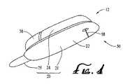
図1は、本発明の一実施形態によるシステム10の概括図を示す。システム10は、送給デバイス12を備える。システム10は、感知デバイス14、コマンド制御デバイス(CCD)16、およびコンピュータ18をさらに備えてよい。種々の実施形態において、送給デバイス12および感知デバイス14は、患者またはユーザ7の身体5の上の所望の位置に固定されてよい。図1における、ユーザ7の身体5に送給デバイス12および感知デバイス14が固定される位置は、代表的な、非限定的な例としてのみ提示される。 FIG. 1 shows a schematic diagram of a
送給デバイス12は、ユーザ7の身体5に流体媒体を送給するように構成される。種々の実施形態において、流体媒体には、液体、流体、ゲル、または同様のものが含まれる。いくつかの実施形態においては、流体媒体には、疾病または病状を治療するための、薬剤または薬物が含まれる。例えば、流体媒体には、糖尿病を治療するためのインスリンが含まれてよく、または、疼痛、癌、肺疾患、HIV、もしくは同様のものを治療するための薬物が含まれてよい。いくつかの実施形態においては、流体媒体には、栄養補給剤、顔料、トレース媒体、生理食塩水媒体、水和物媒体、または同様のものが含まれる。 The
感知デバイス14には、センサデータまたはモニタデータを生成するための、センサ、モニタ、または同様のものが含まれる。種々の実施形態において、感知デバイス14は、ユーザ7の状態を感知するように構成されてよい。例えば、感知デバイス14は、ユーザ7の血糖値または同様のものなどの生物学的状態に反応する、電子機器および酵素を備えてよい。種々の実施形態において、感知デバイス14は、ユーザ7の身体5に固定されてよく、または、送給デバイス12がユーザ7の身体5に固定される位置から隔たった位置にて、ユーザ7の身体5中に埋設されてよい。種々の他の実施形態において、感知デバイス14は、送給デバイス12内に組み込まれてよい。
送給デバイス12、感知デバイス14、CCD16、およびコンピュータ18はそれぞれ、システム10の他の構成要素との通信を可能にする送信機電子機器、受信機電子機器、または送受信機電子機器を備えてよい。感知デバイス14は、送給デバイス12にセンサデータまたはモニタデータを送信するように構成されてよい。また、感知デバイス14は、CCD16と通信するように構成されてもよい。送給デバイス12は、センサデータおよび/または予めプログラムされた送給ルーチンにもとづいて、センサデータを分析し、ユーザ7の身体5に流体媒体を送給するように構成された、電子機器およびソフトウェアを備えてよい。 The
CCD16およびコンピュータ18は、処理、送給ルーチン保存を実施し、送給デバイス12を制御するように構成された、電子機器および他の構成要素を含んでよい。CCD16および/またはコンピュータ18内に制御機能を備えることより、送給デバイス12は、さらに簡素化された電子機器を用いて作製され得る。しかし、いくつかの実施形態においては、送給デバイス12が、全ての制御機能を備えてよく、CCD16およびコンピュータ18を伴わずに作動してよい。種々の実施形態において、CCD16は、可搬式電子デバイスであってよい。また、種々の実施形態において、送給デバイス12および/または感知デバイス14は、CCD16および/またはコンピュータ18によりデータを表示あるいは処理するために、CCD16および/またはコンピュータ18にデータを送信するように構成されてよい。通信および/または制御機能、ならびにデバイスフィーチャセットおよび/またはプログラムオプションのタイプの例は、以下の参考文献、すなわち、(i)「External Infusion Device with Remote Programming、Bolus Estimator and/or Vibration Alarm Capabilities」と題された、2003年5月27日に出願の、米国特許出願整理番号第10/445,477号、(ii)「Handheld Personal Data Assistant (PDA) with a Medical Device and Method of Using the Same」と題された、2003年5月5日に出願の、米国特許出願整理番号第10/429,385号、および(iii)「Control Tabs for Infusion Devices and Methods of Using the Same」と題された、2001年3月21日に出願の、米国特許出願整理番号第09/813,660号において、確認することができる。これらの文献を全て、その全体として本願に引用して援用する。 The
図2は、本発明の一実施形態によるシステム10の一例を示す。図2に図示される本実施形態によるシステム10は、送給デバイス12および感知デバイス14を備える。本発明の一実施形態による送給デバイス12は、使い捨てハウジング20、耐久性ハウジング30、およびリザーバ40を備える。送給デバイス12は、注入経路50をさらに備えてよい。 FIG. 2 illustrates an example of a
通常はユーザの身体に接触する、または通常は送給デバイス12の作動中に流体媒体に接触する、送給デバイス12の要素を、送給デバイス12の使い捨て部分と見なすことができる。例えば、送給デバイス12の使い捨て部分は、使い捨てハウジング20およびリザーバ40を含んでよい。送給デバイス12の使い捨て部分は、特定の使用回数の後に処分することが推奨されてよい。 Elements of the
他方においては、通常は送給デバイス12の作動中にユーザの身体または流体媒体に接触しない送給デバイス12の要素を、送給デバイス12の耐久性部分と見なすことができる。例えば、送給デバイス12の耐久性部分は、耐久性ハウジング30、電子機器(図2には図示せず)、モータおよび駆動リンク装置を有する駆動デバイス(図2には図示せず)、ならびに同様のものを含んでよい。典型的には、送給デバイス12の耐久性ハウジング部分の要素は、送給デバイス12の平常作動の際にはユーザまたは流体媒体との接触によって汚染されず、したがって、送給デバイス12の交換された使い捨て部分と共に再利用するために保存されてよい。 On the other hand, elements of the
種々の実施形態において、使い捨てハウジング20は、リザーバ40を支持し、ユーザの身体に固定するように構成された下面(下方におよび図2におけるページ内に対面する)を有する。ユーザの皮膚に使い捨てハウジング20を接着させるために、接着剤が、使い捨てハウジング20の下面とユーザの皮膚との間の境界面にて使用されてよい。種々の実施形態において、接着剤は、剥離可能カバー層が接着剤材料を覆った状態で、使い捨てハウジング20の下面の上に配設されてよい。この態様においては、接着剤材料を露出させるためにカバー層を剥離することができ、使い捨てハウジング20の接着剤面をユーザの皮膚に対接させて配置することができる。 In various embodiments, the
リザーバ40は、限定しないがインスリンなどの流体媒体を収容するまたは保持するために構成される。種々の実施形態において、リザーバ40は、限定しないが円筒形状容積部、管状形状容積部、または同様のものなどの、流体媒体を受容するための中空内部容積部を備える。いくつかの実施形態においては、リザーバ40は、流体媒体を収容するためのカートリッジまたはキャニスタとして提供されてよい。種々の実施形態において、リザーバ40は、流体媒体で再充填され得る。 The
リザーバ40は、任意の適切な態様において、使い捨てハウジング20によって支持されてよい。例えば、使い捨てハウジング20は、リザーバ40を保持するための、突出部もしくはストラット(図示せず)、またはトラフ構成部(図示せず)を備えてよい。いくつかの実施形態においては、リザーバ40は、リザーバ40を使い捨てハウジング20から取り外すことが可能となり、別のリザーバと交換することが可能となるような態様において、使い捨てハウジング20によって支持されてよい。代替としては、または追加としては、リザーバ40は、適切な接着剤、ストラップ、または他の結合構造部によって、使い捨てハウジング20に固定されてよい。 The
種々の実施形態において、リザーバ40は、リザーバ40の内部容積部内に流体媒体を流入させるのを可能にするための、および/または内部容積部から流体媒体を流出させるのを可能にするための、ポート41を備える。いくつかの実施形態においては、注入経路50は、コネクタ56、チューブ54、および針装置52を備える。注入経路50のコネクタ56は、リザーバ40のポート41に連結可能であってよい。種々の実施形態において、使い捨てハウジング20は、リザーバ40のポート41に注入経路50のコネクタ56を選択的に連結する、およびリザーバ40のポート41から注入経路50のコネクタ56を選択的に連結解除することが可能となるように、リザーバ40のポート41の付近に開口を備えて構成される。 In various embodiments, the
種々の実施形態において、リザーバ40のポート41は、セルフシール式隔壁部または同様のものなどの隔壁部(図2には図示せず)により覆われる、または隔壁部を支持する。隔壁部は、隔壁部が穿刺されない場合には、流体媒体がポート41を通りリザーバ40から流出するのを防ぐように構成されてよい。さらに、種々の実施形態において、注入経路50のコネクタ56は、流体媒体がリザーバ40の内部容積部から流出することが可能になるように、リザーバ40のポート41を覆う隔壁部を穿刺するための針を備える。針/隔壁部コネクタの例は、「Reservoir Connector」と題された、2003年12月22日に出願の、米国特許出願整理番号第10/328,393号において確認することが可能である。この文献を、その全体として本願に引用して援用する。他の代替形態においては、ルエルロックまたは同様のものなどの非隔壁式コネクタが使用されてよい。種々の実施形態において、注入経路50の針装置52は、ユーザの皮膚を穿刺することが可能な針を備える。また、種々の実施形態において、チューブ54は、コネクタ56を針装置52に連結し、注入経路50がリザーバ40からユーザの身体への流体媒体の送給を可能にするための経路を提供することが可能となるように、中空である。 In various embodiments, the
本発明の種々の実施形態による送給デバイス12の耐久性ハウジング30は、使い捨てハウジング20に対合し、固定するように構成された、ハウジングシェルを備える。耐久性ハウジング30および使い捨てハウジング20は、回転式もしくはねじ式連結により、またはこの機械技術において周知のパーツを他の適切な態様で連結することにより、2つのハウジングを相互に共に押し付けることによって2つのパーツを容易に共に連結させることを可能にする、対応するように構成された溝、切欠部、タブ、あるいは他の適切な構成部を備えてよい。種々の実施形態において、耐久性ハウジング30および使い捨てハウジング20は、回転動作を利用して互いに連結されてよい。耐久性ハウジング30および使い捨てハウジング20は、これら2つのハウジングを互いから連結解除させるのに十分な力が加えられた場合に、互いから分離可能であるように構成されてよい。例えば、いくつかの実施形態においては、使い捨てハウジング20および耐久性ハウジング30は、摩擦嵌めによって共にスナップ係合されてよい。種々の実施形態において、耐久性ハウジング30と使い捨てハウジング20との間に水が進入するのを防ぐシールを提供するために、Oリングシールなどの適切なシールが、耐久性ハウジング30および/または使い捨てハウジング20の周縁部に沿って配置されてよい。 The
送給デバイス12の耐久性ハウジング30は、リザーバ40から流体媒体を押し出し、注入経路50などの注入経路内に押しやり、ユーザに送給するために、リザーバ40内の流体媒体に力を加えるための、モータおよび駆動デバイスリンク装置部分を含む駆動デバイス(図2には図示せず)を支持してよい。例えば、いくつかの実施形態においては、電動モータが、リザーバ40内にあるプランジャヘッド(図2には図示せず)に連結されたプランジャアーム(図2には図示せず)にモータを作動的に結合させるための、および、リザーバ40のポート41から流体媒体を押し出してユーザに押しやる方向にプランジャヘッドを駆動させるための、適切なリンク装置と共に、耐久性ハウジング30内に設置されてよい。さらに、いくつかの実施形態においては、モータは、プランジャアームおよびプランジャヘッドを移動させて、患者からリザーバ40内に流体が引き込まれるように、逆方向に制御可能であってよい。モータは、耐久性ハウジング30内に配置されてよく、これに対応して、リザーバ40は、ユーザが、耐久性ハウジング30を送給デバイス12の使い捨てハウジング20に連結させると、自動的に、モータが、適切なリンク装置を介してプランジャヘッドに作動可能に係合するように、使い捨てハウジング20の上に配置されてよい。リンク装置および制御構造部の他の例は、「Control Tabs for Infusion Devices and Methods of Using the Same」と題された、2001年3月21日に出願の、米国特許出願整理番号第09/813,660号において確認することができる。この文献を、その全体として本願に引用して援用する。 The
種々の実施形態において、耐久性ハウジング30および使い捨てハウジング20は、それらの形状を維持するが、上述のように効果的に共に連結し連結解除するのに十分な可撓性および弾性を実現する、適当な剛性の材料から作製されてよい。使い捨てハウジング20の材料は、皮膚との適切な適合性を得るために選択されてよい。例えば、送給デバイス12の使い捨てハウジング20および耐久性ハウジング30は、任意の適切なプラスチック、金属、複合材料、または同様のものから作製されてよい。使い捨てハウジング20は、耐久性ハウジング30と同一のタイプの材料または異なる材料から作製されてよい。いくつかの実施形態においては、使い捨てハウジング20および耐久性ハウジング30は、射出成形プロセスもしくは他の成形プロセス、機械加工プロセス、またはそれらの組合せによって製造されてよい。 In various embodiments, the
例えば、使い捨てハウジング20は、可撓性シリコン、プラスチック、ゴム、合成ゴム、または同様のものなどの、比較的可撓性の材料から作製されてよい。ユーザの皮膚に対して可撓性である材料から使い捨てハウジング20を形成することにより、使い捨てハウジング20がユーザの皮膚に固定される場合に、さらに高いレベルのユーザ快適性が実現され得る。さらに、可撓性の使い捨てハウジング20により、使い捨てハウジング20を固定し得る、ユーザの身体上の部位の選択肢の増加がもたらされ得る。 For example, the
図2に図示される実施形態においては、送給デバイス12は、感知デバイス14の接続要素16を介して感知デバイス14に接続される。感知デバイス14は、送給デバイス12により管理されるべき治療の性質に応じて、任意の適切な生物学的または環境的感知デバイスを備えるセンサ15を備えてよい。例えば、インスリンを糖尿病患者に送給するコンテクストにおいては、センサ15は、血糖センサまたは同様のものを備えてよい。 In the embodiment illustrated in FIG. 2, the
センサ15は、ユーザの皮膚に固定する外部センサであってよく、または、他の実施形態においては、ユーザの身体中の埋設部位に配置される埋設可能センサであってよい。他の代替形態においては、センサは、例えば、「Dual Insertion Set」と題された、2005年6月8日に出願の、米国特許出願整理番号第11/149,119号に示されるような、注入カニューレおよび/または針と共に一部として、あるいは注入カニューレおよび/または針に並設されて、備えられてよい。この文献を、その全体として本願に引用して援用する。図2の図示される例においては、センサ15は、ユーザの皮膚を穿刺するための針を備える使い捨て針パッドと、ユーザの血糖値もしくは同様のものなどの生物学的状態に反応する酵素および/または電子機器とを有する、外部センサである。この態様においては、送給デバイス12は、送給デバイス12がユーザに固定される位置から隔たった部位にてユーザに固定されるセンサ15から、センサデータを供給され得る。 The
図2に図示される実施形態は、送給デバイス12の耐久性ハウジング30内に配置されたセンサ電子機器(図2には図示せず)にセンサデータを供給するために、接続要素16によって接続されたセンサ15を備えるが、他の実施形態は、送給デバイス12内に配置されたセンサ15を使用してよい。さらに他の実施形態は、無線通信リンクによってセンサデータを、送給デバイス12の耐久性ハウジング30内に配置された受信機電子機器(図2には図示せず)と通信するための送信機を有するセンサ15を使用してよい。種々の実施形態において、センサ15と送給デバイス12の耐久性ハウジング30内の受信機電子機器との間の無線通信は、無線周波数(RF)接続、光接続、または別の適切な無線通信リンクを含んでよい。他の実施形態は、感知デバイス14の使用を必要とせず、代わりに、センサデータの利用を伴わずに流体媒体送給機能を実施してよい。 The embodiment illustrated in FIG. 2 is connected by a
上述のように、耐久性要素から送給デバイス12の使い捨て要素を分離させることにより、使い捨て要素を、使い捨てハウジング20の上に配置することが可能となるとともに、耐久性要素を、分離可能な耐久性ハウジング30内に配置することが可能となる。この点に関して、使い捨てハウジング20は、送給デバイス12の規定の使用回数の後に、耐久性ハウジング30から分離されてよく、それにより、使い捨てハウジング20は、適切な態様において処分されてよい。次いで、耐久性ハウジング30は、ユーザに対するさらなる送給の実施のために、新規の(未使用の)使い捨てハウジング20に対合されてよい。 As described above, separating the disposable element of the
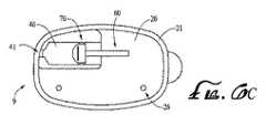
図3は、本発明の別の実施形態による送給デバイス12の一例を図示する。図3の実施形態の送給デバイス12は、図2の実施形態の送給デバイス12と類似のものである。図2に図示される実施形態における送給デバイス12は、耐久性ハウジング30が、リザーバ40を覆うが、図3の実施形態における送給デバイス12は、耐久性ハウジング30が、リザーバ40を覆うことなく使い捨てハウジング20に固定される。図3において図示される実施形態の送給デバイス12は、使い捨てハウジング20を備え、図3において図示される実施形態による使い捨てハウジング20は、土台部21およびリザーバ保持部分24を備える。一実施形態においては、土台部21およびリザーバ保持部分24は、単一の一体構造として形成されてよい。 FIG. 3 illustrates an example of a
使い捨てハウジング20の土台部21は、ユーザの身体に固定されるように構成される。使い捨てハウジング20のリザーバ保持部分24は、リザーバ40を収容するように構成される。使い捨てハウジング20のリザーバ保持部分24は、リザーバ40がリザーバ保持部分24内に収容されている際に、リザーバ保持部分24の外部からリザーバ40のポート41へのアクセスを可能にするための開口を有するように構成されてよい。耐久性ハウジング30は、使い捨てハウジング20の土台部21と着脱可能に構成されてよい。図3において図示される実施形態における送給デバイス12は、リザーバ40内のプランジャヘッド(図3には図示せず)に連結された、またはこのプランジャヘッドに連結可能な、プランジャアーム60を備える。 The
図4は、図3の実施形態の送給デバイス12の別の図を示す。図4において図示される実施形態の送給デバイス12は、使い捨てハウジング20、耐久性ハウジング30、および注入経路50を備える。図4の実施形態における使い捨てハウジング20は、土台部21、リザーバ保持部分24、および剥離可能カバー層25を備える。剥離可能カバー層25は、土台部21の下面22の上の接着剤材料を覆ってよい。剥離可能カバー層25は、土台部21の下面22の上の接着剤材料を露出させるために、ユーザによって剥離可能であるように構成されてよい。いくつかの実施形態においては、土台部21の下面22の上に、剥離可能層によって分離される複数の接着剤層があってよい。 FIG. 4 shows another view of the
図4に図示される本発明の実施形態による注入経路50は、図2の実施形態において図示されるようなコネクタ56、チューブ54、および針装置52ではなく、針58を備える。使い捨てハウジング20の土台部21は、針58が、延在された場合に、土台部21を貫通し、土台部21の下のユーザの皮膚内に進むことが可能となるように、針58の先端部に整列する開口または穿刺可能壁部を備えてよい。この態様においては、針58は、ユーザの皮膚を穿刺し、ユーザに流体媒体を送給するために使用され得る。 The
代替としては、針58は、針58によりユーザの皮膚を穿刺すると、中空カニューレ(図4には図示せず)の端部が針58によってユーザの皮膚を貫通して案内されるように、中空カニューレを貫通して延在されてよい。その後、針58は、リザーバ40からユーザの身体にポンプ注入媒体を送るために、カニューレの一方の端部がユーザの身体内に位置し、カニューレの他方の端部がリザーバ40内の流体媒体と流体流通する状態で、中空カニューレを定位置に残して除去されてよい。 Alternatively, the needle 58 is hollow so that when the needle 58 punctures the user's skin, the end of the hollow cannula (not shown in FIG. 4) is guided through the user's skin by the needle 58. It may extend through the cannula. Thereafter, the needle 58 is positioned with one end of the cannula within the user's body and the other end of the cannula with the fluid medium within the
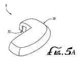
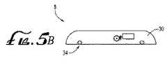
図5Aは、本発明の一実施形態による送給デバイス12(図3を参照)の耐久性部分8を図示する。図5Bは、本発明の一実施形態による耐久性部分8の断面図を図示する。図5Cは、本発明の一実施形態による耐久性部分8の別の断面図を示す。図5A、図5B、および図5Cを参照とすると、種々の実施形態において、耐久性部分8は、耐久性ハウジング30および駆動デバイス80を備える。駆動デバイス80は、モータ84および駆動デバイスリンク装置部分82を備える。種々の実施形態において、耐久性ハウジング30は、モータ84、駆動デバイスリンク装置部分82、他の電子回路、および電源(図5A、図5B、および図5Cには図示せず)を収容するための内部容積部を備えてよい。さらに、種々の実施形態において、耐久性ハウジング30は、プランジャアーム60(図3を参照)を受容するための開口32を備えて構成される。さらに、種々の実施形態において、耐久性ハウジング30は、使い捨てハウジング20(図3を参照)の土台部21と連結するための、タブ、挿入穴、または同様のものなどの、1つ以上の連結部材34を備えてよい。 FIG. 5A illustrates the
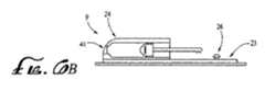
図6Aは、本発明の一実施形態による、送給デバイス12(図3を参照)の使い捨て部分9を図示する。図6Bは、本発明の一実施形態による使い捨て部分9の断面図を示す。図6Cは、本発明の一実施形態による使い捨て部分9の別の断面図を示す。図6A、図6B、および図6Cを参照すると、種々の実施形態において、使い捨て部分9は、使い捨てハウジング20、リザーバ40、プランジャアーム60、およびプランジャヘッド70を備える。いくつかの実施形態においては、使い捨てハウジング20は、土台部21およびリザーバ保持部分24を備える。種々の実施形態において、土台部21は、耐久性ハウジング30(図5Bを参照)の実施形態の1つ以上の連結部材34との連結を可能にするための、タブ、溝、または同様のものなどの、1つ以上の連結部材26を有する上面23を備える。 FIG. 6A illustrates the disposable portion 9 of the delivery device 12 (see FIG. 3), according to one embodiment of the present invention. FIG. 6B shows a cross-sectional view of the disposable portion 9 according to one embodiment of the present invention. FIG. 6C shows another cross-sectional view of the disposable portion 9 according to one embodiment of the present invention. With reference to FIGS. 6A, 6B, and 6C, in various embodiments, the disposable portion 9 comprises a
種々の実施形態において、リザーバ40は、使い捨てハウジング20のリザーバ保持部分24内に収容され、リザーバ40は、流体媒体を保持するように構成される。さらに、種々の実施形態において、プランジャヘッド70は、リザーバ40内に少なくとも部分的に配設され、流体媒体をリザーバ40内に充填し、流体媒体をリザーバ40から押し出すことが可能となるように、リザーバ40内で移動可能である。いくつかの実施形態においては、プランジャアーム60は、プランジャヘッド70に連結される、またはプランジャヘッド70に連結可能である。さらに、いくつかの実施形態においては、プランジャアーム60の一部分が、使い捨てハウジング20のリザーバ保持部分24の外部に延在する。種々の実施形態において、プランジャアーム60は、駆動デバイス80(図5Cを参照)の駆動デバイスリンク装置部分82と噛合するための噛合部分を有する。図5Cおよび図6Cを参照すると、いくつかの実施形態においては、耐久性ハウジング30は、使い捨てハウジング20にスナップ嵌めされてよく、それにより、駆動デバイスリンク装置部分82は、プランジャアーム60の噛合部分に自動的に係合する。 In various embodiments, the
耐久性ハウジング30および使い捨てハウジング20が、プランジャアーム60と係合または噛合する駆動デバイスリンク装置部分82に共に取り付けられる場合には、モータ84は、駆動デバイスリンク装置部分82を駆動するように、したがって、プランジャアーム60を移動させて、プランジャヘッド70をリザーバ40内で移動させるように、制御されてよい。リザーバ40の内部容積部が流体媒体で充填され、注入経路がリザーバ40からユーザの身体まで設けられると、プランジャヘッド70は、リザーバ40内で移動されて、リザーバ40から注入経路内に流体媒体を押しやり、それにより流体媒体をユーザの身体に送給することができる。 When the
種々の実施形態において、リザーバ40が、十分に空になると、または交換を要する場合には、ユーザは、単に、使い捨てハウジング20から耐久性ハウジング30を取り外し、リザーバ40を含む使い捨て部分9を、新たなリザーバを有する新たな使い捨て部分と交換すればよい。耐久性ハウジング30は、新たな使い捨て部分の新たな使い捨てハウジングに連結されてよく、新たな使い捨て部分を備える送給デバイスが、ユーザの皮膚に固定されてよい。種々の他の実施形態においては、リザーバ40が空になる度に使い捨て部分9全体を交換する代わりに、リザーバ40に流体媒体を再充填してよい。いくつかの実施形態においては、リザーバ40は、使い捨てハウジング20のリザーバ保持部分24(図6Bを参照)内に留まりつつ、再充填され得る。さらに、種々の実施形態において、リザーバ40は、新しいリザーバ(図示せず)と交換されてよい一方で、使い捨てハウジング20は、新たなリザーバと共に再利用されてよい。このような実施形態においては、新たなリザーバは、使い捨て部分9内に挿入されてよい。 In various embodiments, when the
図3、図5A、図6B、および図6Cを参照すると、種々の実施形態において、送給デバイス12は、リザーバ状態回路(図示せず)を備え、リザーバ40は、リザーバ回路(図示せず)を備える。種々の実施形態において、リザーバ回路は、(i)リザーバ40を特定する特定ストリング、(ii)リザーバ40の製造業者、(iii)リザーバ40の内容物、および(iv)リザーバ40の内容量、の中の少なくとも1つなど(それらに限定されない)の情報を保存する。いくつかの実施形態においては、送給デバイス12は、リザーバ状態回路(図示せず)を備え、リザーバ状態回路は、リザーバ40が使い捨て部分9内に挿入されると、リザーバ回路からのデータを読み取るように構成される。 Referring to FIGS. 3, 5A, 6B, and 6C, in various embodiments,
種々の実施形態において、リザーバ状態回路は、リザーバ40の内容物の少なくとも一部がリザーバ40から移送された後に、リザーバ40内に依然として残っている内容物の量に関するリザーバ回路内の情報をアップデートするために、リザーバ回路にデータを保存するようにさらに構成される。いくつかの実施形態においては、リザーバ状態回路は、リザーバ40が使い捨て部分9内に挿入される際に、リザーバ40内に依然として残っている内容物の量に関するリザーバ回路内の情報をアップデートするために、リザーバ回路にデータを保存するように構成される。いくつかの実施形態においては、送給デバイス12は、リザーバ状態回路(図示せず)を備え、リザーバ40は、リザーバ回路(図示せず)を備え、リザーバ状態回路は、送給デバイス12の使用を選択的に阻止し、またはリザーバ回路からリザーバ状態回路によって読み取られた情報にもとづいて、警告信号を選択的に生成する。 In various embodiments, the reservoir status circuit updates information in the reservoir circuit regarding the amount of content still remaining in the
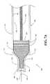
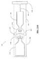
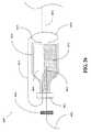
図7Aは、本発明の一実施形態によるシステム100の断面図を示す。システム100は、リザーバ110、プランジャヘッド120、プランジャアーム130、および隔壁部140を備える。種々の実施形態において、システム100は、針150をさらに備える。いくつかの実施形態においては、システム100は、送給デバイス12(図2および図3を参照)の実施形態の要素と同様の要素をさらに備えてよく、この場合には、リザーバ110は、リザーバ40(図2、図3、および図6Cを参照)に対応することとなる。種々の実施形態において、リザーバ110は、適切な金属、プラスチック、セラミック、ガラス、複合材料、または同様のものなど(それらに限定されない)の材料から作製されてよい。種々の実施形態において、プランジャヘッド120は、金属、プラスチック、セラミック、ガラス、複合材料、または同様のものなど(それらに限定されない)の、適当な剛性の材料から作製されてよい。種々の他の実施形態においては、プランジャヘッド120は、弾性的に圧縮可能なプラスチック、ゴム、シリコン、または同様のものなど(それらに限定されない)の、圧縮可能材料から作製されてよい。 FIG. 7A shows a cross-sectional view of
種々の実施形態において、リザーバ110は、本体部分111、本体頭隙またはネック部分112、および、本体部分111とネック部分112とを連結する湾曲部分または傾斜部分117を備える。リザーバ110は、外側面113および内側面114を有する。リザーバ110の内側面114は、リザーバ110の中空内部を画成し、リザーバ110の中空内部は、流体媒体を収容することが可能である。リザーバ110は、ネック部分112の端部にポート118をさらに備え、このポート118を介して、流体媒体は、リザーバ110の中空内部内に充填され、リザーバ110の中空内部から押し出され得る。リザーバ110の本体部分111は、任意の適切な形状を有してよく、例えば、円筒形状、管状形状、バレル形状、球形状、矩形断面を有する形状、または同様のものなどを有してよい。同様に、リザーバ110のネック部分112は、任意の適切な形状を有してよく、例えば、円筒形状、管状形状、バレル形状、球形状、矩形断面を有する形状、または同様のものなどを有してよい。 In various embodiments, the
プランジャヘッド120は、リザーバ110内に配置され、リザーバ110の軸方向に移動可能であり、それにより、流体媒体が中に収容され得るリザーバ110の内部容積部を膨張または収縮させる。プランジャヘッド120は、リザーバ110の軸方向へのプランジャアーム130の移動が、リザーバ110の軸方向へのプランジャヘッド120の移動を生じさせるように、プランジャアーム130に連結される。プランジャヘッド120は、プランジャ本体部分121、プランジャ頭隙またはネック部分122、および、プランジャ本体部分121とプランジャネック部分122とを連結するプランジャ湾曲部分または傾斜部分123を備える。種々の実施形態において、プランジャヘッド120は、プランジャ本体部分121の一部分を囲む、1つ以上のOリング125をさらに備える。 The
プランジャ本体部分121は、プランジャ本体部分121の外側面の形状が、リザーバ110の本体部分111の内側面の形状と実質的に合致する、または実質的に同一であるように、形状設定される。種々の実施形態において、プランジャ本体部分121は、プランジャヘッド120がリザーバ110内で摺動することが可能となるように、リザーバ110の本体部分111の内側面の直径よりも若干小さい直径を有する。いくつかの実施形態においては、プランジャ本体部分121の上の1つ以上のOリング125は、プランジャヘッド120がリザーバ110内にある場合には、リザーバ110の本体部分111の内側面と接触状態にある。 The
プランジャネック部分122は、プランジャネック部分122の外側面の形状が、リザーバ110のネック部分112の内側面の形状に実質的に合致する、または実質的に同一であるように、形状設定される。種々の実施形態において、プランジャネック部分122は、プランジャネック部分122がリザーバ110のネック部分112内で摺動することが可能となるように、リザーバ110のネック部分112の内側面の直径よりも若干小さい直径を有する。いくつかの実施形態においては、プランジャネック部分122の外側面の直径は、リザーバ110のネック部分112の内側面の直径の少なくとも90%である。さらに、いくつかの実施形態においては、プランジャネック部分122は、プランジャヘッド120がリザーバ110内で完全に前進されると、プランジャネック部分122がリザーバ110のネック部分112内の区域の少なくとも80%を占めるように、形状設定される。プランジャ傾斜部分123は、プランジャ傾斜部分123の外側面の形状が、リザーバ110の傾斜部分117の内側面の形状に実質的に合致する、または実質的に同一であるように、形状設定される。 The
隔壁部140は、リザーバ110のポート118に配置される。隔壁部140は、ゴム、シリコンゴム、ポリウレタン、または、針により穿刺され、針の周囲にシールを形成し得る他の材料など(それらに限定されない)の、適切な材料から形成されてよい。ネック部分112は、傾斜部分117の端部から隔壁部140まで、ある一定の長さを有する。種々の実施形態において、プランジャネック部分122は、リザーバ110のネック部分112の特定の長さと実質的に同一の長さを有する。いくつかのこのような実施形態においては、プランジャネック部分122は、プランジャヘッド120がリザーバ110内で完全に前進される場合に、リザーバ110のネック部分112内の実質的に全長にわたって延在することが可能である。したがって、いくつかの実施形態においては、プランジャヘッド120が、リザーバ110内で完全に前進される場合には、プランジャネック部分122の端部が、隔壁部140に接近し得る、または接触状態となり得る。種々の実施形態において、プランジャネック部分122の端部からプランジャ傾斜部分123までのプランジャネック部分122の長さは、隔壁部140からリザーバ110の傾斜部分117までのリザーバ110のネック部分112の長さの少なくとも90%である。 The
隔壁部140は、流体媒体が、針150を通り、リザーバ110の中空内部内に送られるのを可能にするように、針150によって穿刺することが可能である。種々の実施形態において、プランジャヘッド120は、プランジャヘッド120がリザーバ110内で十分に前進され、隔壁部140が針150によって穿刺される場合に、針150の一部分を収容することが可能な、穴またはチャネルまたは逃がし部または空洞部124を備える。空洞部124は、針150の一部分を収容するための任意の適切な形状を有してよく、例えば、円筒形状、半球底部を有する管状形状、矩形断面を有する形状、または同様のものなどを有してよい。種々の実施形態において、空洞部124の直径は、針150の端部が空洞部124内に嵌入することが可能となるように、針150の直径よりも大きい。 The
種々の実施形態において、空洞部124は、プランジャヘッド120のプランジャネック部分122内に位置する。いくつかの実施形態においては、隔壁部140からプランジャ本体部分121への方向における、プランジャネック部分122内の空洞部124の長さは、プランジャネック部分122の長さの4分の1よりも長い。さらに、いくつかの実施形態においては、空洞部124は、プランジャネック部分122の端部面の中央部に配置される。種々の実施形態において、リザーバ110のネック部分112の端部は、針150が、プランジャヘッド120の空洞部124と整列された位置でのみ隔壁部140を穿刺し得るように、隔壁部140を部分的に覆う。 In various embodiments, the
図8は、本発明の一実施形態による方法の流れ図を示す。図7Aおよび図8を参照すると、種々の実施形態において、図8の方法により、流体媒体でリザーバ110を充填し、流体媒体をリザーバ110から押し出すことが可能である。S10においては、リザーバ110の隔壁部140が、針150により穿刺され、この方法は、S11へと続く。S11においては、プランジャヘッド120は、針150の少なくとも一部分がプランジャヘッド120の空洞部124内に受容されるように、リザーバ110内で前進される。例えば、プランジャアーム130は、モータ(図7Aには図示せず)によって、または、リザーバ110内でプランジャヘッド120を前進させるようにユーザにより加えられる力によって、駆動されてよい。種々の実施形態において、プランジャヘッド120を移動させることは、プランジャネック部分122がリザーバ110のネック部分112内に少なくとも部分的に延在するように、リザーバ110内でプランジャヘッド120を移動させることを含む(S12)。さらに、種々の実施形態において、プランジャヘッド120を移動させることは、プランジャヘッド120の一部分が隔壁部140の一部分に接触するように、リザーバ110内でプランジャヘッド120を移動させることを含む(S13)。いくつかの実施形態においては、プランジャヘッド120が移動され、次いで隔壁部140が針150により穿刺されるように、S10およびS11が、逆の順序にて実施される。 FIG. 8 shows a flowchart of a method according to an embodiment of the invention. With reference to FIGS. 7A and 8, in various embodiments, the method of FIG. 8 can fill the
プランジャヘッド120が、リザーバ110内で十分に前進されると、針150の一部分が、プランジャネック部分122の空洞部124内に延在してよく、これにより、プランジャネック部分122は、隔壁部140まで実質的に完全に延在することが可能となり得る。その結果、プランジャヘッド120が、リザーバ110内で完全に前進される場合に、プランジャヘッド120の端部と隔壁部140との間に空気ポケットが存在することが、実質的に制限され得る、または解消され得る。リザーバ110を充填する前に、プランジャヘッド120と隔壁部140との間の空気ポケットを低減させることは、それにより、流体媒体がリザーバ110内に引き込まれる際に続いて流体媒体に進入する気泡の量が制限されるため、有益である。 When the
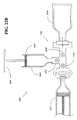
種々の実施形態において、この方法は、次いでS14に続く。S14においては、プランジャヘッド120は、リザーバ110内で引き戻されて、それにより流体媒体は、針150を通りリザーバ110内に流入することが可能となる。例えば、プランジャアーム130は、モータ(図7Aには図示せず)によって、または、プランジャヘッド120をリザーバ110内に引き戻させるようにユーザにより加えられる引張り力によって、引き戻されてよい。図7Bは、プランジャヘッド120がリザーバ110内で部分的に引き戻された場合の、本発明の一実施形態によるシステム100の断面図を示す。プランジャヘッド120をリザーバ110内で引き戻すことにより、流体媒体は、針150を通り、リザーバ110の中空内部内に進むことが可能となる。例えば、針150の一方の端部が、リザーバ110内に位置してよく、針150の別の端部が、バイアル(図7Bには図示せず)または、流体媒体を保管する他の容器内に位置してよく、流体媒体が、針150を通りバイアルからリザーバ110に進んでよい。いくつかの実施形態においては、針150は、トランスファーガードまたは他の同様のデバイスの一部である。リザーバ110内の空気の量が、リザーバ110を充填する前に制限されたため、流体媒体がリザーバ110内に充填される際の流体媒体中の気泡の量もまた、制限される。流体媒体中の気泡の存在を制限するまたは低減させることは、それにより、後にリザーバ110から患者またはユーザの中に押し出される気泡の量が制限され、したがって、ある特定の量の流体媒体をユーザに送給する際の送給精度の向上を助けるため、有益である。 In various embodiments, the method then continues to S14. In S <b> 14, the
図7A、図7B、および図8を参照すると、図8の方法は、次いでS15に続き、針150が、リザーバ110から取り除かれる。種々の実施形態において、隔壁部140は、自己回復式隔壁部であり、針150がリザーバ110および隔壁部140から取り除かれると、隔壁部140は、流体媒体がリザーバ110内に保持されるように閉じる。この方法は、次いでS16に続いてよい。S16においては、リザーバ110の隔壁部140は、別の針により穿刺される。例えば、リザーバ110の隔壁部140は、注入経路50(図2を参照)のコネクタ56(図2を参照)の針などの、流通経路のコネクタの針によって穿刺されてよい。この方法は、次いでS17に続く。 Referring to FIGS. 7A, 7B, and 8, the method of FIG. 8 then continues to
S17においては、別の針の少なくとも一部分が、プランジャヘッド120の空洞部内に受容されるまで、プランジャヘッド120が、リザーバ110内で前進されて、それにより別の針を介してリザーバ110から流体媒体を押し出す。図7Aは、プランジャヘッド120が、リザーバ110内で実質的に完全に前進された場合のシステム100を図示する。プランジャヘッド120が、リザーバ110内で前進されると、リザーバ110の内側面に対するプランジャヘッド120の緊密嵌めの形状により、リザーバ110内に残る、無駄になる流体媒体の量が制限または低減される。したがって、プランジャヘッド120が完全に前進された場合に、リザーバ110のネック部分112内に非常に緊密に嵌合するように形状設定されたプランジャネック部分122を備えるプランジャヘッド120を用いることにより、流体媒体中の気泡の存在が、リザーバ110の充填の際に制限され得るようになり、流体媒体がリザーバ110から押し出される際の、無駄になる流体媒体の量が低減され得る。この方法は、次いでS18において終了する。 In S17, the
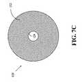
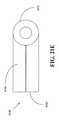
図7Cは、本発明の一実施形態によるプランジャヘッド120のプランジャネック部分122の前方向からの断面図を示す。プランジャネック部分122は、針を収容するための空洞部124を備える。種々の実施形態において、空洞部124は、プランジャネック部分122の面の中央部の実質的に近傍に配置される。図7Dは、本発明の一実施形態によるプランジャヘッド120の側面図を示す。プランジャヘッド120は、プランジャ本体部分121、プランジャネック部分122、およびプランジャ傾斜部分123を備える。種々の実施形態において、プランジャ本体部分121は、1つ以上のくぼみ部または空洞部126を備え、このくぼみ部または空洞部126の中には、1つ以上のOリング125(図7Aを参照)が配置されてよい。 FIG. 7C shows a cross-sectional view from the front of the
図9A、図10A、図11A、図12A、および図12Cは、流体媒体と共に送給される気泡の数を低減させるように気泡を捕獲することを可能にする形状を有するリザーバを備える、本発明の種々の実施形態によるシステムを図示する。このようなシステムは、気泡捕獲形状を有するため、および、流体媒体と共に送給される気泡の数を低減させることにより、ある特定の量の流体媒体の送給を試みる際の送給精度を向上させることが可能となり得るため、このようなシステムにより、気泡管理が可能となる。したがって、このようなシステムは、標準的なリザーバ形状よりも大量の気泡の捕獲を可能にし、それにより捕獲された気泡がリザーバ内に留まり、流体媒体と共に送給されないようにする、リザーバ形状を提供する。 9A, 10A, 11A, 12A, and 12C comprise a reservoir having a shape that allows trapping bubbles to reduce the number of bubbles delivered with a fluid medium. 1 illustrates a system in accordance with various embodiments of FIGS. Such a system improves the delivery accuracy when attempting to deliver a certain amount of fluid media because it has a bubble capture shape and by reducing the number of bubbles delivered with the fluid media. Such a system would allow bubble management. Thus, such a system provides a reservoir shape that allows capture of a larger amount of bubbles than a standard reservoir shape, thereby preventing the trapped bubbles from remaining in the reservoir and being delivered with the fluid medium. To do.
いくつかの実施形態においては、図9A、図10A、図11A、図12A、および図12Cにおけるシステムが、送給デバイス12(図2および図3を参照)の実施形態の要素と同様の要素を備えてよく、この場合には、それらのシステムにおけるリザーバは、リザーバ40(図2、図3、図6Cを参照)に対応することとなる。種々の実施形態において、図9A、図10A、図11A、図12A、および図12Cにおけるシステムのリザーバは、適切な金属、プラスチック、セラミック、ガラス、複合材料、または同様のものなど(それらに限定されない)の材料から作製されてよい。種々の実施形態において、これらの図面におけるシステムのプランジャヘッドは、金属、プラスチック、セラミック、ガラス、複合材料、または同様のものなど(それらに限定されない)の、適当な剛性の材料から作製されてよい。種々の他の実施形態において、これらのシステムにおけるプランジャヘッドは、弾性的に圧縮可能なプラスチック、ゴム、シリコン、または同様のものなど(それらに限定されない)の、圧縮可能材料から作製されてよい。 In some embodiments, the system in FIGS. 9A, 10A, 11A, 12A, and 12C includes elements similar to those in the embodiment of the delivery device 12 (see FIGS. 2 and 3). In this case, the reservoir in these systems will correspond to the reservoir 40 (see FIGS. 2, 3 and 6C). In various embodiments, the reservoir of the system in FIGS. 9A, 10A, 11A, 12A, and 12C can be, but is not limited to, a suitable metal, plastic, ceramic, glass, composite, or the like ) Material. In various embodiments, the plunger head of the system in these drawings may be made from a suitable rigid material, such as, but not limited to, metal, plastic, ceramic, glass, composite, or the like. . In various other embodiments, the plunger heads in these systems may be made from a compressible material, such as, but not limited to, an elastically compressible plastic, rubber, silicone, or the like.
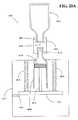
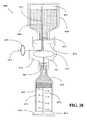
図9Aは、本発明の一実施形態によるシステム200の断面図を示す。システム200は、リザーバ210、プランジャヘッド220、およびプランジャアーム230を備える。リザーバ210は、本体部分211、気泡捕獲部分212、およびポート217を備える。リザーバ210は、外側面213および内側面214を有する。リザーバ210の内側面214は、リザーバ210の中空内部を画成し、リザーバ210の中空内部は、流体媒体を収容することが可能である。リザーバ210のポート217により、流体媒体は、リザーバ210の中空内部内に充填され得る、またはリザーバ210の中空内部から押し出され得る。リザーバ210の本体部分211は、円筒形状、管状形状、バレル形状、球形状、矩形断面を有する形状、または同様のものなど(それらに限定されない)の、任意の適切な形状を有してよい。 FIG. 9A shows a cross-sectional view of a
プランジャヘッド220は、リザーバ210内に配置され、リザーバ210の軸方向に移動可能であり、それにより、流体媒体が中に収容され得るリザーバ210の容積部を膨張または収縮させる。プランジャヘッド220は、リザーバ210の軸方向へのプランジャアーム230の移動が、リザーバ210の軸方向へのプランジャヘッド220の移動を生じさせるように、プランジャアーム230に連結される。プランジャヘッド220は、プランジャ本体部分221およびプランジャ突出部分222を備える。種々の実施形態において、プランジャヘッド220は、プランジャ本体部分221の一部分を囲む1つ以上のOリング225をさらに備える。種々の実施形態において、1つ以上のOリング225は、ゴム、プラスチック、複合材料、または同様のものなど(それらに限定されない)の、任意の適切な材料から作製されてよい。 The
リザーバ210の気泡捕獲部分212は、リザーバ210の内部中に容積部216を有するように形状設定され、それにより、流体媒体がリザーバ210からポート217を通り押し出される際に、流体媒体中の気泡がリザーバ210の内部中の容積部216中に捕獲され得るようにする。種々の実施形態において、気泡捕獲部分212の内側面は、ポート217の付近で湾曲されて、または角度をつけられて、容積部216を画成する。いくつかの実施形態においては、気泡捕獲部分212は、リザーバ210の本体部分211から、本体部分211の内部容積部からの流体媒体がポート217に通じるリザーバ210の区域またはチャネル272内に移動することが可能となる、リザーバ210の箇所218を越えて延在する。 The
種々の実施形態において、リザーバ210は、プランジャヘッド220がリザーバ210内で前進されると、流体媒体がポート217を通り進むとともに、リザーバ210中の気泡がリザーバ210の気泡捕獲部分212の湾曲面または角度面により画成された容積部216内に集まることが可能となるように、形状設定される。リザーバ210のこのような形状により、従来のリザーバ形状と比較して、流体媒体と共に送給される気泡の量を低減させることが可能となる。いくつかの実施形態においては、リザーバ210の気泡捕獲部分212は、本体部分211により画成された内部容積部から外方に湾曲され、流体媒体は、本体部分211により画成された内部容積部からポート217に直接進むことが可能である。いくつかの実施形態においては、リザーバ210の気泡捕獲部分212の表面215は、気泡が表面215に実質的に付着せず、ポート217から離れて容積部216の方向にそらされるように、表面仕上げ部分または材料を含む。種々の実施形態において、このような表面仕上げ部分または材料は、疎水性材料、親水性材料、または他の適切な材料を含む。 In various embodiments, the
プランジャ本体部分221は、プランジャ本体部分221の形状が、リザーバ210の本体部分211の内側形状と実質的に合致する、または実質的に同一であるように、形状設定される。種々の実施形態において、プランジャ本体部分221は、プランジャヘッド220がリザーバ210内で摺動することが可能となるように、リザーバ210の本体部分211の内側面の直径よりも若干小さい直径を有する。いくつかの実施形態においては、プランジャ本体部分221の上の1つ以上のOリング225は、プランジャヘッド220がリザーバ210内にある場合には、リザーバ210の本体部分211の内側面と接触状態にある。 The
種々の実施形態において、プランジャ突出部分222は、プランジャ突出部分222の形状がリザーバ210の気泡捕獲部分212の内側形状に実質的に合致する、または実質的に同一であるように、形状設定される。いくつかの実施形態においては、プランジャ突出部分222は、湾曲され、プランジャ本体部分221から突出する。種々の実施形態において、プランジャ突出部分222は、プランジャ突出部分222がリザーバ210の容積部216内で摺動することが可能となるように、および、プランジャヘッド220がリザーバ210内で完全に前進される場合に空気の死容積のためのスペースが残されるように、リザーバ210の気泡捕獲部分212の内側面によって画成された領域よりも若干小さな寸法を有する。したがって、種々の実施形態において、リザーバ210およびプランジャヘッド220の形状により、流体媒体がリザーバ210のポート217から押し出されつつある際に、気泡捕獲部分212の容積部216内に気泡を捕獲することが可能となる。 In various embodiments, the
種々の実施形態において、プランジャ突出部分222は、プランジャヘッド220がリザーバ210内で完全に前進される場合に、プランジャ突出部分222が気泡捕獲部分212の容積部216の少なくとも80%を占めるような、寸法を有する。さらに、種々の実施形態において、プランジャ突出部分222は、プランジャヘッド220がリザーバ210内で完全に前進される場合に、気泡捕獲部分212の容積部216の98%未満を占め、それにより、プランジャヘッド220がリザーバ210内で完全に前進される場合に、空気を保持するための1つ以上の空気ポケットがプランジャ突出部分222と気泡捕獲部分212の内側面との間に存在することとなる。いくつかの実施形態においては、プランジャ突出部分222は、プランジャヘッド220がリザーバ210内で十分に前進される場合に、気泡捕獲部分212の容積部216内に少なくとも部分的に延在する。 In various embodiments, the
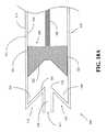
図9Bは、本発明の一実施形態によるリザーバ210の断面図を示す。図9Bは、リザーバ210の種々の構成部を強調するために陰影をつけられる。リザーバ210は、本体部分211、気泡捕獲部分212、およびポート217を備える。本体部分211は、流体媒体を収容するための内部容積部270を有する。ポート217は、本体部分211の内部容積部270と流体流通状態にある。気泡捕獲部分212は、流体媒体が内部容積部270から押し出されつつある際に、流体媒体中に存在する気泡を捕獲するために、本体部分211の内部容積部270と流体流通状態にある容積部216を有する。 FIG. 9B shows a cross-sectional view of a
種々の実施形態において、ポート217は、内部容積部270のある特定の側に配置され、気泡捕獲部分212は、内部容積部270のこの特定の側に配置される。さらに、種々の実施形態において、気泡捕獲部分212は、内部容積部270から離れるように本体部分211から延在する第1の部分281と、内部容積部270の方向に戻る第2の部分282とを有する。いくつかの実施形態においては、本体部分211および気泡捕獲部分212は、単一のシームレスユニットとして共に形成される。さらに、いくつかの実施形態においては、気泡捕獲部分212の第1の部分281は、内部容積部270から離れるように本体部分211から延在し、気泡捕獲部分212の第2の部分282は、第1の部分281から内部容積部270の方向に延在する。 In various embodiments, the
種々の実施形態において、気泡捕獲部分212は、第1の端部領域284、第2の端部領域285、および、第1の端部領域284と第2の端部領域285との間の中間領域286を有する、湾曲面283を備える。いくつかの実施形態においては、第1の端部領域284および第2の端部領域285は、中間領域286から内部容積部270までよりも、本体部分211の内部容積部270に近い。さらに、いくつかの実施形態においては、第1の端部領域284は、本体部分211と接触状態にあり、第2の端部領域285は、本体部分211の内部容積部270に隣接して配置される。 In various embodiments, the
種々の実施形態において、気泡捕獲部分212の湾曲面283は、流体媒体が気泡捕獲部分212の容積部216内に存在する場合に、流体媒体と接触状態にある。他の実施形態においては、湾曲面283は、略U字型である。図9Bは、断面図を示すが、気泡捕獲部分212は、3次元においては、例えば略半トロイド状として形状設定されてよい。種々の実施形態において、リザーバ210は、流体媒体が気泡捕獲部分212の容積部216からポート217に流れるためには、流体媒体が本体部分211の内部容積部270を通り流れなければならないように、形状設定される。いくつかの実施形態においては、リザーバ210は、本体部分211の内部容積部270からポート217に通じるチャネル272を備え、気泡捕獲部分212は、チャネル272の少なくとも一部分を丸く囲む。 In various embodiments, the
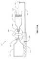
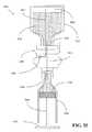
図10Aは、本発明の一実施形態によるシステム300の断面図を示す。システム300は、リザーバ310、プランジャヘッド320、およびプランジャアーム330を備える。リザーバ310は、本体部分311、気泡捕獲部分312、およびポート317を備える。リザーバ310は、外側面313および内側面314を有する。リザーバ310の内側面314は、リザーバ310の中空内部を画成し、リザーバ310の中空内部は、流体媒体を収容することが可能である。リザーバ310のポート317により、流体媒体は、リザーバ310の中空内部内に充填され得る、またはリザーバ310の中空内部から押し出され得る。リザーバ310の本体部分311は、円筒形状、管状形状、バレル形状、球形状、矩形断面を有する形状、または同様のものなど(それらに限定されない)の、任意の適切な形状を有してよい。 FIG. 10A shows a cross-sectional view of a
プランジャヘッド320は、リザーバ310内に配置され、リザーバ310の軸方向に移動可能であり、それにより、流体媒体が中に収容され得るリザーバ310の容積部を膨張または収縮させる。プランジャヘッド320は、リザーバ310の軸方向へのプランジャアーム330の移動が、リザーバ310の軸方向へのプランジャヘッド320の移動を生じさせるように、プランジャアーム330に連結される。プランジャヘッド320は、プランジャ本体部分321およびプランジャ突出部分322を備える。種々の実施形態において、プランジャヘッド320は、プランジャ本体部分321の一部分を囲む、1つ以上のOリング325をさらに備える。 The
リザーバ310の気泡捕獲部分312は、リザーバ310の内部中に容積部316を有するように形状設定され、それにより、流体媒体がリザーバ310からポート317を通り押し出される際に、流体媒体中の気泡が気泡捕獲部分312の容積部316中に捕獲され得るようにする。種々の実施形態において、気泡捕獲部分312の内側面は、ポート317の付近で実質的に直線状のある角度で角度をつけられて、容積部316を画成する。いくつかの実施形態においては、気泡捕獲部分312は、リザーバ310の本体部分311から、本体部分311の内部容積部からの流体媒体がポート317に通じるリザーバ310の区域またはチャネル372内に移動することが可能となる、リザーバ310の箇所318を越えて、延在する。 The
種々の実施形態において、リザーバ310は、プランジャヘッド320がリザーバ310内で前進されると、流体媒体がポート317を通り進むとともに、リザーバ310中の気泡がリザーバ310の気泡捕獲部分312の実質的に直線状の角度面により画成された容積部316内に集まることが可能となるように、形状設定される。リザーバ310のこのような形状により、従来のリザーバ形状と比較して、流体媒体と共に送給される気泡の量を低減させることが可能となり得る。いくつかの実施形態においては、リザーバ310の気泡捕獲部分312は、本体部分311により画成されたリザーバ310の内部領域から外方に角度をつけられ、流体媒体は、本体部分311により画成されたリザーバ310の内部領域からポート317に直接進むことが可能である。いくつかの実施形態においては、リザーバ310の気泡捕獲部分312の表面315は、気泡が表面315に実質的に付着せず、ポート317から離れて容積部316の方向にそらされるように、表面仕上げ部分または材料を含む。 In various embodiments, the reservoir 310 is configured such that as the
プランジャ本体部分321は、プランジャ本体部分321の形状が、リザーバ310の本体部分311の内側面の形状と実質的に合致する、または実質的に同一であるように、形状設定される。種々の実施形態において、プランジャ本体部分321は、プランジャヘッド320がリザーバ310内で摺動することが可能となるように、リザーバ310の本体部分311の内側面の直径よりも若干小さい直径を有する。いくつかの実施形態においては、プランジャ本体部分321の上の1つ以上のOリング325は、プランジャヘッド320がリザーバ310内にある場合には、リザーバ310の本体部分311の内側面と接触状態にある。 The
種々の実施形態において、プランジャ突出部分322は、プランジャ突出部分322の形状がリザーバ310の気泡捕獲部分312の内側形状に実質的に合致する、または実質的に同一であるように、形状設定される。いくつかの実施形態においては、プランジャ突出部分322は、プランジャ本体部分321から実質的に直線状のある角度で角度をつけられ、プランジャ本体部分321から突出する。種々の実施形態において、プランジャ突出部分322は、プランジャ突出部分322が気泡捕獲部分312の容積部316内で摺動することが可能となるように、および、プランジャヘッド320がリザーバ310内で完全に前進される場合に空気の死容積のためのスペースが残されるように、リザーバ310の気泡捕獲部分312の内側面によって画成された領域よりも若干小さな寸法を有する。したがって、種々の実施形態において、リザーバ310およびプランジャヘッド320の形状により、流体媒体がリザーバ310のポート317から押し出されつつある際に、気泡捕獲部分312の容積部316内に気泡を捕獲することが可能となる。 In various embodiments, the
種々の実施形態において、プランジャ突出部分322は、プランジャヘッド320がリザーバ310内で完全に前進される場合に、プランジャ突出部分322が気泡捕獲部分312の容積部316の少なくとも80%を占めるような、寸法を有する。さらに、種々の実施形態において、プランジャ突出部分322は、プランジャヘッド320がリザーバ310内で完全に前進される場合に、気泡捕獲部分312の容積部316の98%未満を占め、それにより、プランジャヘッド320がリザーバ310内で完全に前進される場合に、空気を保持するための1つ以上の空気ポケットがプランジャ突出部分322と気泡捕獲部分312の内側面との間に存在することとなる。いくつかの実施形態においては、プランジャ突出部分322は、プランジャヘッド320がリザーバ310内で十分に前進される場合に、気泡捕獲部分312の容積部316内に少なくとも部分的に延在する。 In various embodiments, the
図10Bは、本発明の一実施形態によるリザーバ310の断面図を示す。図10Bは、リザーバ310の種々の構成部を強調するために陰影をつけられる。リザーバ310は、本体部分311、気泡捕獲部分312、およびポート317を備える。本体部分311は、流体媒体を収容するための内部容積部370を有する。ポート317は、本体部分311の内部容積部370と流体流通状態にある。気泡捕獲部分312は、流体媒体が内部容積部370から押し出されつつある際に、流体媒体中に存在する気泡を捕獲するために、本体部分311の内部容積部370と流体流通状態にある容積部316を有する。 FIG. 10B shows a cross-sectional view of a reservoir 310 according to one embodiment of the invention. FIG. 10B is shaded to highlight various components of the reservoir 310. The reservoir 310 includes a
種々の実施形態において、ポート317は、内部容積部370のある特定の側に配置され、気泡捕獲部分312は、内部容積部370のこの特定の側に配置される。さらに、種々の実施形態において、気泡捕獲部分312は、内部容積部370から離れるように本体部分311から延在する第1の部分381と、内部容積部370の方向に戻る第2の部分382とを有する。いくつかの実施形態においては、本体部分311および気泡捕獲部分312は、単一のシームレスユニットとして共に形成される。さらに、いくつかの実施形態においては、気泡捕獲部分312の第1の部分381は、内部容積部370から離れるように本体部分311から延在し、気泡捕獲部分312の第2の部分382は、第1の部分381から内部容積部370の方向に延在する。 In various embodiments, the
種々の実施形態において、リザーバ310は、流体媒体が気泡捕獲部分312の容積部316からポート317に流れるためには、流体媒体が本体部分311の内部容積部370を通り流れなければならないように、形状設定される。いくつかの実施形態においては、リザーバ310は、本体部分311の内部容積部370からポート317に通じるチャネル372を備え、気泡捕獲部分312は、チャネル372の少なくとも一部分を丸く囲む。 In various embodiments, the reservoir 310 may allow the fluid medium to flow through the interior volume 370 of the
種々の実施形態において、気泡捕獲部分312は、気泡捕獲部分312の容積部316の端部を画成する第1の表面383と、気泡捕獲部分312の容積部316の別の端部を画成する第2の表面384とを備え、第2の表面384は、第1の表面383に対してある角度をなして配置される。いくつかの実施形態においては、第1の表面383と第2の表面384との間の角度は、90度未満である。さらに、いくつかの実施形態においては、第1の表面383は、リザーバ310の本体部分311の内側面に対して平坦である。種々の実施形態において、ポート317は、内部容積部370のある特定の側に配置され、気泡捕獲部分312の第1の部分381は、本体部分311からこの特定の側に延在する。 In various embodiments, the
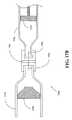
図11Aは、本発明の一実施形態によるシステム400の断面図を示す。システム400は、リザーバ410、プランジャヘッド420、およびプランジャアーム430を備える。リザーバ410は、本体部分411、気泡捕獲部分412、およびポート417を備える。リザーバ410は、外側面413および内側面414を有する。リザーバ410の内側面414は、リザーバ410の中空内部を画成し、リザーバ410の中空内部は、流体媒体を収容することが可能である。リザーバ410のポート417により、流体媒体は、リザーバ410の中空内部内に充填され得る、またはリザーバ410の中空内部から押し出され得る。リザーバ410の本体部分411は、円筒形状、管状形状、バレル形状、球形状、矩形断面を有する形状、または同様のものなど(それらに限定されない)の、任意の適切な形状を有してよい。 FIG. 11A shows a cross-sectional view of a
プランジャヘッド420は、リザーバ410内に配置され、リザーバ410の軸方向に移動可能であり、それにより、流体媒体が中に収容され得るリザーバ410の容積部を膨張または収縮させる。プランジャヘッド420は、リザーバ410の軸方向へのプランジャアーム430の移動が、リザーバ410の軸方向へのプランジャヘッド420の移動を生じさせるように、プランジャアーム430に連結される。プランジャヘッド420は、プランジャ本体部分421およびプランジャ突出部分422を備える。種々の実施形態において、プランジャヘッド420は、プランジャ本体部分421の一部分を囲む、1つ以上のOリング425をさらに備える。 The
リザーバ410の気泡捕獲部分412は、リザーバ410の内部中に容積部416を有するように形状設定され、それにより、流体媒体がリザーバ410からポート417を通り押し出される際に、流体媒体中の気泡が気泡捕獲部分412の容積部416中に捕獲され得るようにする。種々の実施形態において、リザーバ410は、プランジャヘッド420がリザーバ410内で前進されると、流体媒体がポート417を通り進むとともに、リザーバ410中の気泡がリザーバ410の容積部416内に集まることが可能となるように、形状設定される。リザーバ410のこのような形状により、従来のリザーバ形状と比較して、流体媒体と共に送給される気泡の量を低減させることが可能となり得る。 The
プランジャ本体部分421は、プランジャ本体部分421の外側面の形状が、リザーバ410の本体部分411の内側面の形状と実質的に合致する、または実質的に同一であるように、形状設定される。種々の実施形態において、プランジャ本体部分421は、プランジャヘッド420がリザーバ410内で摺動することが可能となるように、リザーバ410の本体部分411の内側面の直径よりも若干小さい直径を有する。いくつかの実施形態においては、プランジャ本体部分421の上の1つ以上のOリング425は、プランジャヘッド420がリザーバ410内にある場合には、リザーバ410の本体部分411の内側面と接触状態にある。種々の実施形態において、プランジャ突出部分422は、プランジャ突出部分422の外側面の形状がリザーバ410の気泡捕獲部分412の内側面の形状に実質的に合致する、または実質的に同一であるように、形状設定される。 The
図11Bは、本発明の一実施形態によるリザーバ410の断面図を示す。図11Bは、リザーバ410の種々の機能部を強調するために陰影をつけられる。リザーバ410は、本体部分411、気泡捕獲部分412、およびポート417を備える。本体部分411は、流体媒体を収容するための内部容積部470を有する。ポート417は、本体部分411の内部容積部470と流体流通状態にある。気泡捕獲部分412は、流体媒体が内部容積部470から押し出されつつある際に、流体媒体中に存在する気泡を捕獲するために、本体部分411の内部容積部470と流体流通状態にある容積部416を有する。 FIG. 11B shows a cross-sectional view of a
種々の実施形態において、ポート417は、内部容積部470のある特定の側に配置され、気泡捕獲部分412は、内部容積部470のこの特定の側に配置される。さらに、種々の実施形態において、気泡捕獲部分412は、内部容積部470から離れるように本体部分411から延在する第1の部分481と、内部容積部470の方向に戻る第2の部分482とを有する。いくつかの実施形態においては、本体部分411および気泡捕獲部分412は、単一のシームレスユニットとして共に形成される。さらに、いくつかの実施形態においては、気泡捕獲部分412の第1の部分481は、内部容積部470から離れるように本体部分411から延在し、気泡捕獲部分412の第2の部分482は、第1の部分481から内部容積部470の方向に延在する。 In various embodiments, the
種々の実施形態において、気泡捕獲部分412は、湾曲面483を備える。いくつかの実施形態においては、気泡捕獲部分412の湾曲面483は、流体媒体が気泡捕獲部分412の容積部416内に存在する場合に、流体媒体と接触状態にある。種々の実施形態において、リザーバ410は、流体媒体が気泡捕獲部分412の容積部416からポート417に流れるためには、流体媒体が本体部分411の内部容積部470を通り流れなければならないように、形状設定される。いくつかの実施形態においては、リザーバ410は、本体部分411の内部容積部470からポート417に通じるチャネル472を備え、気泡捕獲部分412は、チャネル472の少なくとも一部分を丸く囲む。 In various embodiments, the
図11Aおよび図11Bを参照とすると、種々の実施形態において、プランジャ突出部分422は、プランジャ突出部分422の形状が、リザーバ410の気泡捕獲部分412の内側形状と実質的に合致する、または実質的に同一であるように、形状設定される。いくつかの実施形態においては、プランジャ突出部分422は、少なくとも部分的に湾曲され、プランジャ本体部分421から突出する。さらに、いくつかの実施形態においては、プランジャ突出部分は、リザーバ410の本体部分411の内側面に対して実質的に平行である表面を備える。種々の実施形態において、プランジャ突出部分422は、プランジャ突出部分422がリザーバ410の容積部416内で摺動することが可能となるように、および、プランジャヘッド420がリザーバ410内で完全に前進される場合に空気の死容積のためのスペースが残されるように、リザーバ410の気泡捕獲部分412の内側面によって画成された領域よりも若干小さな寸法を有する。したがって、種々の実施形態において、リザーバ410およびプランジャヘッド420の形状により、流体媒体がリザーバ410のポート417から押し出されつつある際に、気泡捕獲部分412の容積部416内に気泡を捕獲することが可能となる。 Referring to FIGS. 11A and 11B, in various embodiments, the
種々の実施形態において、プランジャ突出部分422は、プランジャヘッド420がリザーバ410内で完全に前進される場合に、プランジャ突出部分422が気泡捕獲部分412の容積部416の少なくとも80%を占めるような、寸法を有する。さらに、種々の実施形態において、プランジャ突出部分422は、プランジャヘッド420がリザーバ410内で完全に前進される場合に、気泡捕獲部分412の容積部416の98%未満を占め、それにより、プランジャヘッド420がリザーバ410内で完全に前進される場合に、空気を保持するための1つ以上の空気ポケットがプランジャ突出部分422と気泡捕獲部分412の内側面との間に存在することとなる。いくつかの実施形態においては、プランジャ突出部分422は、プランジャヘッド420がリザーバ410内で十分に前進される場合に、気泡捕獲部分412の容積部416内に少なくとも部分的に延在する。 In various embodiments, the
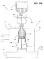
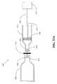
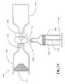
図12Aは、本発明の一実施形態によるシステム500の断面図を示す。システム500は、リザーバ510、プランジャヘッド520、およびプランジャアーム530を備える。種々の実施形態において、システム500は、針550をさらに備える。リザーバ510は、システム200(図9Aを参照)のリザーバ210と類似のものであり、本体部分511および気泡捕獲部分512を備える。気泡捕獲部分512は、気泡を捕獲するための容積部516を画成する。したがって、リザーバ510は、気泡の捕獲を可能にする空気捕獲形状を有する。 FIG. 12A shows a cross-sectional view of a
プランジャヘッド520は、システム200(図9Aを参照)のプランジャヘッド220と類似のものである。プランジャヘッド520は、プランジャ本体部分521およびプランジャ突出部分522を備える。プランジャヘッド520は、プランジャヘッド520がリザーバ510内で完全に前進される場合に、リザーバ510の内部中に針550の少なくとも一部分を挿入することを可能にするためのくぼみ部または逃がし部523をさらに備える。種々の実施形態において、プランジャヘッド520は、プランジャヘッド520がリザーバ510内で十分に前進され、針550の少なくとも一部分がリザーバ510内に挿入される場合に、針550の前記部分を受容するための逃がし部523を有する。種々の実施形態において、リザーバ510は、気泡を捕獲するように形状設定される。さらに、種々の実施形態において、リザーバ510およびプランジャヘッド520は、流体媒体がリザーバ510から押し出される際の気泡の送給を最小限に抑えるように形状設定される。 The
図12Bは、本発明の一実施形態によるリザーバ510の断面図を示す。図12Bは、リザーバ510の種々の構成部を強調するために陰影をつけられる。リザーバ510は、本体部分511、気泡捕獲部分512、およびポート517を備える。本体部分511は、流体媒体を収容するための内部容積部570を有する。ポート517は、本体部分511の内部容積部570と流体流通状態にある。気泡捕獲部分512は、流体媒体が内部容積部570から押し出されつつある際に、流体媒体中に存在する気泡を捕獲するために、本体部分511の内部容積部570と流体流通状態にある容積部516を有する。 FIG. 12B shows a cross-sectional view of a
種々の実施形態において、ポート517は、内部容積部570のある特定の側に配置され、気泡捕獲部分512は、内部容積部570のこの特定の側に配置される。さらに、種々の実施形態において、気泡捕獲部分512は、内部容積部570から離れるように本体部分511から延在する第1の部分581と、内部容積部570の方向に戻る第2の部分582とを有する。いくつかの実施形態においては、本体部分511および気泡捕獲部分512は、単一のシームレスユニットとして共に形成される。さらに、いくつかの実施形態においては、気泡捕獲部分512の第1の部分581は、内部容積部570から離れるように本体部分511から延在し、気泡捕獲部分512の第2の部分582は、第1の部分581から内部容積部570の方に延在する。 In various embodiments, the
種々の実施形態において、気泡捕獲部分512は、第1の端部領域584、第2の端部領域585、および、第1の端部領域584と第2の端部領域585との間の中間領域586を有する、湾曲面583を備える。いくつかの実施形態においては、第1の端部領域584および第2の端部領域585は、中間領域586から内部容積部570までよりも、本体部分511の内部容積部570に近い。さらに、いくつかの実施形態においては、第1の端部領域584は、本体部分511と接触状態にあり、第2の端部領域585は、本体部分511の内部容積部570に隣接して配置される。 In various embodiments, the
種々の実施形態において、気泡捕獲部分512の湾曲面583は、流体媒体が気泡捕獲部分512の容積部516内に存在する場合に、流体媒体と接触状態にある。他の実施形態においては、湾曲面583は、略U字型である。図12Bは、断面図を示すが、気泡捕獲部分512は、3次元においては、例えば略半トロイド状として形状設定されてよい。種々の実施形態において、リザーバ510は、流体媒体が気泡捕獲部分512の容積部516からポート517に流れるためには、流体媒体が本体部分511の内部容積部570を通り流れなければならないように、形状設定される。いくつかの実施形態においては、リザーバ510は、本体部分511の内部容積部570からポート517に通じるチャネル572を備え、気泡捕獲部分512は、チャネル572の少なくとも一部分を丸く囲む。 In various embodiments, the
図12Cは、本発明の別の実施形態による、図12Aのシステム500の断面図を示す。図12Cに図示される実施形態においては、システム500は、プラグ560をさらに備える。種々の実施形態において、プラグ560は、リザーバ510の気泡捕獲部分512の内側面515と、流体媒体がリザーバから押し出されることが可能なリザーバの位置との間に配置される。プラグ560は、気泡がリザーバ510のポート517を通り供給されるのを実質的に防ぐ、例えば親水性材料または疎水性材料などを含んでよい。その結果、リザーバ510から押し出される気泡の数がプラグ560によってさらに制限されるため、送給精度を向上させることが可能となり得る。種々の実施形態において、プラグ560は、流体媒体がリザーバ510の本体部分511の内部容積部から押し出されつつある際に、流体媒体中の気泡を、リザーバ510のポート517から離れるように、および、気泡捕獲部分512の容積部516の方向にそらす。 FIG. 12C shows a cross-sectional view of the
図13Aは、本発明の一実施形態によるシステム600の断面図を示す。システム600は、リザーバ610、プランジャヘッド620、プランジャアーム630、トランスファーガード640、バイアル650、および振動装置670を備える。バイアル650により流体媒体を収容することが可能であり、バイアル650は、針などにより穿刺され得るバイアル隔壁部652を備える。トランスファーガード640は、流体媒体を移送するための針642を備える。リザーバ610は、針642などの針により穿刺され得る隔壁部614を備える。振動装置670は、保持ユニット675およびバイブレータ677を備える。種々の実施形態において、振動装置670は、1つ以上のサポート673、1つ以上のラッチ674、および、電源678をさらに備える。電源678は、例えば、電気ソケットにバイブレータ677をプラグ接続するための電気プラグ、および、バイブレータ677に電力供給するための電池、または同様のものなどを備えてよい。種々の実施形態において、バイブレータ677は、電動バイブレータ、または同様のものである。 FIG. 13A shows a cross-sectional view of a
保持ユニット675により、リザーバ610を保持することが可能となる。種々の実施形態において、保持ユニット675は、リザーバ610を保持するための、第1のホルダ671および第2のホルダ672を備える。保持ユニット675は、保持ユニット675がリザーバ610を保持しており、リザーバ610が流体媒体で充填されつつある場合に、リザーバ610内にあるプランジャヘッド620に連結されるプランジャアーム630が移動可能となるように、構成される。バイブレータ677により、保持ユニット675を振動させて、それによりリザーバ610を振動させることが可能となる。種々の実施形態において、バイブレータ677は、保持ユニット675がリザーバ610を保持しており、リザーバ610が流体媒体で充填されつつある場合に、保持ユニット675を振動させ、それにより、リザーバ610を振動させ、流体媒体内の気泡をリザーバ610内で上方に移動させるように、構成される。さらに、種々の実施形態において、バイブレータ677は、保持ユニット675がリザーバ610を保持しており、リザーバ610が流体媒体で充填されつつある場合に、保持ユニット675を十分に揺さぶり、それにより、流体媒体中の気泡を揺さぶり自由な状態にするように、構成される。 The holding
いくつかの実施形態においては、保持ユニット675は、第1のホルダ671および第2のホルダ672を備え、プランジャアーム630は、リザーバ610が第1のホルダ671および第2のホルダ672に保持されており、リザーバ610が流体媒体で充填されつつある場合に、第1のホルダ671と第2のホルダ672との間のスペース676内で移動可能である。種々の実施形態において、第1のホルダ671および第2のホルダ672は、バイブレータ677に連結される。さらに、種々の実施形態において、スペース676は、プランジャアーム630とバイブレータ677との間にも少なくとも部分的に位置する。いくつかの実施形態においては、第1のホルダ671および第2のホルダ672の一方または両方が、ヒンジ(図示せず)によりバイブレータ677に装着され、それにより、第1のホルダ671および第2のホルダ672は、揺動して開くことが可能となって、リザーバ610を第1のホルダ671と第2のホルダ672との間に少なくとも部分的に配置することが可能となり、次いで、揺動して閉じ、それによりリザーバ610が第1のホルダ671と第2のホルダ672との間にしっかりと保持されるようにロックすることが可能となる。さらに、いくつかの実施形態においては、保持ユニット675は、第1のホルダ671とリザーバ610との間に、および、第2のホルダ672とリザーバ610との間に、クッション693をさらに備える。種々の実施形態において、保持ユニット675は、リザーバ610が中に挿入され固定的に保持され得る、単一部材である。 In some embodiments, the holding
種々の実施形態において、保持ユニット675は、保持ユニット675がリザーバ610を保持している場合に、流体媒体が、プランジャアーム630からプランジャヘッド620の対向側に配置されたリザーバ610のポート680を通り、リザーバ610内に充填され得るように、構成される。さらに、種々の実施形態において、保持ユニット675は、保持ユニット675がリザーバ610を保持しており、リザーバ610が流体媒体で充填されつつある場合に、プランジャアーム630がバイブレータ677の方向に移動可能であるように、構成される。いくつかの実施形態においては、振動装置670は、1つ以上のラッチ674を備え、1つ以上のラッチ674により、保持ユニット675がリザーバ610を保持している場合に、および、リザーバ610が流体媒体で充填される前に、プランジャアーム630が移動されるのを防ぐことが可能になる。このような実施形態においては、1つ以上のラッチ674は、揺動して開いて、または引き戻って、プランジャアーム630がスペース676内で移動することが可能となるように制御されて、それにより、リザーバ610が流体媒体で充填され得るようにすることができる。 In various embodiments, the holding
種々の実施形態において、システム600は、トランスファーガード640を備え、トランスファーガード640により、保持ユニット675がリザーバ610を保持している場合に、バイアル650からリザーバ610に流体媒体を移送することが可能となる。いくつかの実施形態においては、トランスファーガード640は、トランスファーガード640の針642がリザーバ610のポート680中の隔壁部614を穿刺する場合に、リザーバ610のポート680を少なくとも部分的に囲むための、第1の端部647を備える。種々の実施形態において、保持ユニット675は、保持ユニット675がリザーバ610を保持しており、リザーバ610が流体媒体で充填されつつある場合に、プランジャアーム630に連結されたハンドル632がリザーバ610とバイブレータ677との間のスペース676内で移動可能であるように、構成される。 In various embodiments, the
いくつかの実施形態においては、ハンドル632は、バイブレータ677がリザーバ610を振動させている間に、ユーザによって引かれてよい。種々の他の実施形態において、ハンドル632は、1つ以上のラッチ674が開かれる場合に、ハンドル632を移動させて、プランジャヘッド620を移動させるように、ばね(図示せず)に連結される。いくつかの実施形態においては、このシステムは、保持ユニット675がリザーバ610を保持している際に、ハンドル632を移動させて、プランジャヘッド620を移動させるためのモータ(図示せず)をさらに備える。さらに、いくつかの実施形態においては、ハンドル632は、リザーバ610が流体媒体で充填された後に、ハンドル632がプランジャアーム630から連結解除され得るように、プランジャアーム630から連結解除され得る。種々の実施形態において、振動装置670は、保持ユニット675を支持するための1つ以上のサポータ673を備え、1つ以上のサポータ673は、スタンド(図示せず)または同様のものに装着されてよい。 In some embodiments, the
充填プロセスの際に、トランスファーガード640の針642により、バイアル650とリザーバ610との間に流体経路が設けられる。1つ以上のラッチ674が解除されると、流体は、リザーバ610内に流入することが可能となる。リザーバ610が、流体媒体で充填されている間に、バイブレータ677は、流体媒体中の気泡がリザーバ610内で上方に移動するように、リザーバ610を振動させてよい。したがって、種々の実施形態において、バイブレータ677により、リザーバ610を揺さぶり、それにより、リザーバ610内に充填されつつある流体媒体中の気泡を揺さぶり自由な状態にすることが可能となる。種々の実施形態において、システム600において充填プロセスが完了すると、バイアル650は、トランスファーガード640から連結解除され、リザーバ610内の空気は、ハンドル632を押すことによって押し出される。 During the filling process, the
図14は、本発明の一実施形態による方法の流れ図を示す。図13Aおよび図14を参照すると、S20において、リザーバ610が、保持ユニット675により保持される。この方法は、次いでS21に続く。S21においては、リザーバ610のポート680内に配置された隔壁部614が、トランスファーガード640の針642により穿刺されて、流体媒体を、バイアル650からリザーバ610へと針642を介して移送することが可能となる。この方法は、次いでS22に続く。S22においては、保持ユニット675がリザーバ610を保持している場合に、1つ以上のラッチ674が移動されて、プランジャアーム630が移動可能となる。この方法は、次いでS23に続く。 FIG. 14 shows a flow diagram of a method according to an embodiment of the invention. Referring to FIGS. 13A and 14, the
S23においては、保持ユニット675がリザーバ610を保持している場合に、プランジャアーム630が、リザーバ610内でプランジャヘッド620を移動させるように移動されて、流体媒体をリザーバ610内に充填することが可能となる。種々の実施形態において、この移動は、保持ユニット675がリザーバ610を保持している場合に、プランジャアーム630をバイブレータ677の方向に移動させて、リザーバ610内でプランジャヘッド620を移動させて、流体媒体をリザーバ610内に充填することを可能にすることを含む(S24)。図13Bは、保持ユニット675がリザーバ610を保持している場合に、プランジャアーム630が移動されて、流体媒体をリザーバ610内に充填することが可能となった場合の、本発明の一実施形態によるシステム600の断面図を示す。図14のこの方法は、次いでS25に続く。 In S23, when the holding
図13A、図13B、および図14を参照すると、S25においては、バイブレータ677が、リザーバ610を振動させるように、保持ユニット675を振動させる。種々の実施形態において、この振動は、保持ユニット675がリザーバ610を保持しており、リザーバ610が流体媒体で充填されつつある場合に、バイブレータ677により保持ユニット675を振動させることを含む(S26)。さらに、種々の実施形態において、この振動は、リザーバ610を振動させるように、バイブレータ677により保持ユニット675を振動させて、流体媒体内の気泡をリザーバ610内で上方に移動させることを含む(S27)。この方法は、次いでS28に続く。S28においては、リザーバ610が振動された後に、空気がリザーバ610から押し出される。例えば、バイアル650が、トランスファーガード640から取り外されてよく、ハンドル632が、リザーバ610から空気を押し出すように押されてよい。この方法は、次いでS29において終了する。 Referring to FIG. 13A, FIG. 13B, and FIG. 14, in S25,
図15は、本発明の一実施形態によるシステム3500の断面図を示す。システム3500は、リザーバ3510、プランジャヘッド3520、プランジャアーム3530、隔壁部3540、1つ以上の疎水性フィルタ3571、および、1つ以上の空気通路3572を備える。リザーバ3510は、流体媒体を収容するための中空内部を有する。プランジャヘッド3520は、リザーバ3510内に配置され、リザーバ3510の軸方向に移動可能であり、それにより、リザーバ3510の内部容積部を膨張または収縮させる。リザーバは、ネック部分3512を備える。隔壁部3540は、リザーバ3510のネック部分3512の端部に配置され、流体チャネル3550が、リザーバ3510のネック部分3512内に画成されて、隔壁部3540から延在する。 FIG. 15 shows a cross-sectional view of a
1つ以上の空気通路3572は、リザーバ3510内から、流体媒体がリザーバ3510から貫通して押し出される外側面と同一の、リザーバ3510の外側面まで延在する。種々の実施形態において、1つ以上の空気通路3572は、流体チャネル3550を囲む。1つ以上の疎水性フィルタ3571は、リザーバ3510内の1つ以上の空気通路3572の端部に配置される。疎水性フィルタ3571は、リザーバ3510内の流体媒体が1つ以上の空気通路3572に進入するのを実質的に防ぐ疎水性材料を含む。1つ以上の空気通路3572により、リザーバ内の空気は、1つ以上の疎水性フィルタ3571を通過し、リザーバ3510から出ることが可能となる。 One or
本発明による一方法により、流体媒体をリザーバ3510から押し出すことが可能となる。この方法の第1のステップにおいては、流体通路が、隔壁部3540を貫通して流体チャネル3550まで設けられる。この方法の第2のステップにおいては、プランジャヘッド3520が、リザーバ3510内で押し下げられて、それにより流体媒体が、流体チャネル3550を通り、隔壁部3540を貫通してリザーバ3510から押し出される。流体媒体が、流体チャネル3550を通り押し出されつつある場合に、リザーバ3510内の空気は、1つ以上の疎水性フィルタ3571を通過して、1つ以上の空気通路3572を通りリザーバから出ることが可能である。1つ以上の疎水性フィルタ3571により、流体媒体が1つ以上の空気通路3572に進入することが、実質的に防がれる。したがって、この方法によれば、流体媒体が、リザーバ3510から押し出され得る一方で、リザーバ3510内の空気は、流体媒体がリザーバ3510から出るのと同一の、リザーバ3510の側において、リザーバ3510からの出口を有する1つ以上の空気通路3572を通り漏出することが可能となる。 One method according to the present invention allows the fluid medium to be pushed out of the
図16Aは、本発明の一実施形態によるシステム3600の断面図を示す。システム3600は、リザーバ3610、プランジャヘッド3620、プランジャアーム3630、トランスファーガード3640、バイアル3650、および圧力供給デバイス3660を備える。リザーバ3610は、流体媒体を収容するための中空内部を有する。プランジャヘッド3620は、リザーバ3610内に配置され、リザーバ3610の軸方向に移動可能であり、それにより、リザーバ3610の内部容積部を膨張または収縮させる。プランジャアーム3630は、プランジャヘッド3620に連結される。種々の実施形態において、リザーバ3610は、針によって穿刺され得る隔壁部3618を備え、それにより、この針が隔壁部3618を穿刺すると、リザーバ3610の中空内部が、針を通り進む流体媒体で充填され得る。 FIG. 16A shows a cross-sectional view of a
バイアル3650は、バイアル3650の内側面3651に連結される隔膜3653を備える。バイアル3650の内側面3651と、隔膜3653の外側面とが、流体媒体を収容することが可能なバイアル3650の内部容積部を画成する。種々の実施形態において、隔膜3653は、ゴム、プラスチック、または同様のものを含み、可撓性である。いくつかの実施形態においては、バイアル3650は、針により穿刺され得る隔壁部3654をさらに備え、それにより、この針が隔壁部3654を穿刺すると、流体媒体を、バイアル3650から針を通して押し出すことが可能となる。種々の実施形態において、バイアル3650は、開口を有する底面3652を備え、この開口により、空気または他の動因物が、バイアル3650内の流体媒体と接触状態にある隔膜3653の側からは隔膜3653の対向側の、バイアル3650内に進入することが可能となる。
トランスファーガード3640は、バイアル3650の内部容積部からリザーバ3610の内部容積部までの流体経路を与えるための、1つ以上の針3642を備える。種々の実施形態において、トランスファーガード3640は、ユーザがトランスファーガード3640によりバイアル3650およびリザーバ3610を連結している場合に、1つ以上の針3642がユーザの手に接触するのを防ぐのを補助する壁部を備える。トランスファーガード3640の1つ以上の針3642は、バイアル3650の隔壁部3654およびリザーバ3610の隔壁部3618を穿刺して、バイアル3650からリザーバ3610までの流体経路を与えることが可能である。種々の実施形態において、流体媒体がバイアル3650からリザーバ3610まで流体流経路に沿って進む際に、気泡を捕獲するために、膜が、トランスファーガード3640内の流体流経路中に組み込まれてよい。 The
圧力供給デバイス3660は、流体などの空気または他の動因物をバイアル3650の底面3652中の開口に押し通すための、例えば注入器または同様のものを備えてよい。種々の他の実施形態において、圧力供給デバイス3660は、圧力を供給するための、例えばポンプまたは同様のものなどを備えてよい。圧力供給デバイス3660は、例えば気密式コネクタ、ねじ込み式連結部、クランプ、または同様のものなどにより、連結箇所3670にてバイアル3650に連結される。図16Aにおいては、圧力供給デバイス3660は、中空内部を画成する内側面3661、プランジャヘッド3662、プランジャヘッド3662に連結されるプランジャアーム3663、および、プランジャアーム3663に連結されるハンドル3664を有する、注入器として図示される。注入器は、ハンドル3664が押されて、プランジャヘッド3662が注入器の内部内で前進される場合に、空気または他の動因物が注入器から押し出されるように、構成される。 The
本発明の一実施形態による一方法により、システム3600においてリザーバ3610を充填することが可能となる。この方法の第1のステップは、圧力供給デバイス3660をバイアル3650の一端部に連結し、トランスファーガード3640を用いてバイアル3650の別の端部をリザーバ3610に連結することである。このように連結された構造体の一例が、図16Aに図示される。この方法の第2のステップは、圧力供給デバイス3660を使用して、流体媒体と接触状態にある隔膜3653の側に対向するバイアル3650内の隔膜3653の側に圧力を加えることである。例えば、圧力供給デバイスが注入器を備える場合においては、ハンドル3664が加圧されて、注入器内でプランジャヘッド3662を前進させ、バイアル3650内に空気または他の動因物を押し出し、それにより、隔膜3653に圧力を加える。 One method according to one embodiment of the present invention allows the
バイアル3650内の隔膜3653は、可撓性であり、そのため隔膜3653は、圧力が圧力供給デバイス3660により隔膜3653に加えられると、膨張する。図16Bは、圧力供給デバイス3660のプランジャヘッド3662が前進されて、バイアル3653内の隔膜3653の一方の側の圧力が上昇し、それにより隔膜3653がバイアル3650内で膨張させられた場合を図示する。圧力供給デバイス3660からの圧力により隔膜3653が膨張すると、流体媒体が中に収容されるバイアル3650の内部容積部は、寸法が縮小され、その結果、流体媒体は、バイアル3650から押し出されて、流体経路を通りリザーバ3610の内部容積部に送られる。リザーバ3610の内部容積部への流体媒体の流入により、プランジャヘッド3620は、リザーバ3610内で後方に移動される。所望の量の流体媒体が、リザーバ3610内に充填されるまで、圧力供給デバイス3660からバイアル3650の隔膜3653に漸増圧力が加えられてよい。 The
したがって、本発明の実施形態は、バイアルの底部に可撓性隔膜を形成し、外圧が可撓性隔膜に加えられて、インスリンまたは同様のものなどの流体媒体がリザーバ内に押し入れられるのを可能にする。種々の実施形態において、膜が、気泡を捕獲するために流体流経路内に組み込まれる。システム3600を使用するこの方法のいくつかの実施形態においては、リザーバ3610を充填する前に、バイアル3650が、初期真空排気されて、リザーバ3610のデッドスペース内の空気をバイアル3650内に排出する。 Thus, embodiments of the present invention form a flexible diaphragm at the bottom of the vial, allowing external pressure to be applied to the flexible diaphragm to allow fluid media such as insulin or the like to be pushed into the reservoir. To. In various embodiments, a membrane is incorporated into the fluid flow path to capture bubbles. In some embodiments of this
図17Aは、本発明の一実施形態によるシステム3700の断面図を示す。システム3700は、リザーバ3710、プランジャヘッド3720、プランジャアーム3750、トランスファーガード3740、バイアル3750、および移動可能要素3770を備える。リザーバ3710は、流体媒体を収容するための中空内部を有する。プランジャヘッド3720は、リザーバ3710内に配置され、リザーバ3710の軸方向に移動可能であり、それにより、リザーバ3710の内部容積部を膨張または収縮させる。プランジャアーム3730は、プランジャヘッド3720に連結される。種々の実施形態において、リザーバ3710は、針により穿刺され得る隔壁部3718を備え、それにより、この針が隔壁部3718を穿刺すると、リザーバ3710の中空内部が、針を通り進む流体媒体で充填され得る。 FIG. 17A shows a cross-sectional view of a
移動可能要素3770は、バイアル3750内に配置され、バイアル3750内で移動可能であり、それにより、バイアル3750の内部容積部を膨張または収縮させる。バイアル3750の内側面3751と、移動可能要素3770の表面とが、流体媒体を収容することが可能なバイアル3750の内部容積部を画成する。種々の実施形態において、移動可能要素3770は、ゴム、プラスチック、または同様のものを含む。さらに、種々の実施形態において、移動可能要素3770は、プランジャまたは同様のものを備える。いくつかの実施形態においては、バイアル3750は、針により穿刺され得る隔壁部3754をさらに備え、それにより、この針が隔壁部3754を穿刺すると、流体媒体をバイアル3750から針を通して押し出すことが可能となる。 The
移動可能要素3770は、圧力が移動可能要素3770に加えられる場合に、バイアル3750内で移動することが可能である。種々の実施形態において、移動可能要素は、バレル部分3771および湾曲部分3772を備え、バレル部分3771の外側面の形状は、バイアル3750のバレル部分3755の内側面3751の形状と実質的に同一であり、湾曲部分3772の外側面の形状は、バイアル3750の湾曲部分3756の形状と実質的に同一である。さらに、種々の実施形態において、移動可能要素3770は、1つ以上のOリング3773を備え、このOリング3773は、移動可能要素3770のバレル部分3771を囲み、移動可能要素3770がバイアル3750内に位置する場合には、バイアル3750のバレル部分3755の内側面3751と接触状態にある。 The
トランスファーガード3740は、バイアル3750の内部容積部からリザーバ3710の内部容積部までの流体経路を与えるための、1つ以上の針3742を備える。種々の実施形態において、トランスファーガード3740は、ユーザがトランスファーガード3740によりバイアル3750およびリザーバ3710を連結している場合に、1つ以上の針3742がユーザの手に接触するのを防ぐのを補助する壁部を備える。トランスファーガード3740の1つ以上の針3742は、バイアル3750の隔壁部3754およびリザーバ3710の隔壁部3718を穿刺して、バイアル3750からリザーバ3710までの流体経路を与えることが可能である。種々の実施形態において、トランスファーガード3740は、流体媒体がバイアル3750からリザーバ3710まで流体流経路に沿って進む際に、気泡を捕獲するために、トランスファーガード3740の流体流経路中に組み込まれる膜3741を備えてよい。 The
本発明の一実施形態による一方法により、システム3700においてリザーバ3710を充填することが可能となる。この方法の第1のステップは、トランスファーガード3740を用いてバイアル3750をリザーバ3710に連結することである。このように連結された構造体の一例が、図17Aに図示される。この方法における第2のステップは、流体媒体と接触状態にある移動可能要素3770の側の対向側に位置するバイアル3750内の移動可能要素3770の側に圧力を加えることである。例えば、ユーザまたはデバイスが、移動可能要素3770の外側面を押圧して、バイアル3750内で移動可能要素を前進させてよい。したがって、移動可能要素3770は、保管用バイアル3750の移動可能底部としての役割を果たす。種々の実施形態において、移動可能要素3770は、移動可能要素3770に圧力を加えるための、移動可能要素3770に連結されたハンドル(図示せず)をさらに備えてよい。 One method according to one embodiment of the present invention allows the
圧力が、移動可能要素3770に加えられて、バイアル3750内で移動可能要素3770を前進させると、バイアル3750内の流体媒体は、針3742を通り、リザーバ3710内に押しやられる。図17Bは、移動可能要素3770がバイアル3750内で少なくとも部分的に前進された場合の、システム3700の断面図を示す。力が、移動可能要素3770に加えられて、バイアル3750から流体媒体を押しやりリザーバ3710を充填すると、プランジャヘッド3720が、リザーバ3710に進入する流体媒体の力により、リザーバ3710内で後方に押しやられる。したがって、本発明の実施形態により、移動可能底部を有する保管用バイアルが可能となり、リザーバを充填するために保管用バイアルの移動可能底部に圧力を加えることが可能となる。さらに、流体媒体が、バイアル3750からリザーバ3710に進むと、流体媒体は、トランスファーガード3740の膜3741を貫通して送られ、この膜3741により、流体媒体がリザーバ3710を充填する前に、流体媒体から気泡が実質的に除去される。 As pressure is applied to the
図18Aは、本発明の一実施形態によるシステム3800の断面図を示す。システム3800は、脱気具3801およびバイアル3830を備える。脱気具3801は、第1のハンドル3802、第2のハンドル3804、枢動部材3810、第1のアーム3808、第2のアーム3806、保持アーム3812、プランジャハウジング3824、プランジャヘッド3820、プランジャアーム3822、および挿入部材3850を備える。バイアル3830は、インスリンまたは同様のものなどの流体媒体を、バイアル3830内のある一定レベルまで収容し、流体媒体の上方のバイアル3830の区域が、バイアル3830の頭隙3844を形成する。バイアルは、脱気具3801の挿入部材3850により穿刺され得る隔壁部3832を備える。 FIG. 18A shows a cross-sectional view of a
第1のハンドル3802、第2のハンドル3804、第1のアーム3808、および第2のアーム3806は、枢動部材3810により共に連結される。種々の実施形態において、第1のハンドル3802、枢動部材3810、および第1のアーム3808が、単一ユニットとして形成され、第2のハンドル3804および第2のアーム3806が、単一ユニットとして形成される。第1のハンドル3802は、第2のハンドル3804の方向におよび第2のハンドル3804から離れるように枢動することが可能である。第2のアーム3806は、バイアルのネックを囲むための空洞部を有してよい。保持アーム3812は、第2のアーム3806から延在し、第1のアーム3808と第2のアーム3806との間にプランジャハウジング3824を保持する。プランジャヘッド3820は、プランジャアーム3822に連結され、プランジャヘッド3820は、プランジャハウジング3824内で摺動することが可能である。挿入部材3850は、例えば針であってよく、プランジャハウジング3824の出口ポートに連結される。プランジャアーム3822は、第1のアーム3808に連結される。
脱気具3801は、第1のハンドル3802が第2のハンドル3804から離れるように枢動されると、第1のアーム3808が枢動して、プランジャアーム3822によりプランジャヘッド3820がプランジャハウジング3824内で前進されて、プランジャヘッド3820と挿入部材3850への出口ポートとの間のプランジャハウジング3822内の容積部を縮小するように、構成される。さらに、脱気具3801は、第1のハンドル3802が第2のハンドル3804の方向に枢動されると、第1のアーム3808が枢動されて、プランジャアーム3822によりプランジャヘッド3820がプランジャハウジング3824内で引き戻されて、プランジャヘッド3820と挿入部材3850への出口ポートとの間のプランジャハウジング3822内の容積部を拡大するように、構成される。 When the
本発明による一方法により、脱気具3801を用いてバイアル3830を脱気することが可能である。第1のステップにおいては、脱気具3801の第1のハンドル3802が、第2のハンドル3804から離れるように枢動され、これにより、第1のアーム3808が、プランジャアーム3822を押し、したがって、プランジャハウジング3824内でプランジャヘッド3820を前進させる。第2のステップにおいては、挿入部材3850が、バイアル3830の隔壁部3832を通り、バイアル3830内の流体媒体3842の上方の、バイアル3830の頭隙3844内に挿入される。脱気具3801およびバイアル3830のこのような連結の一例が、図18Aに図示される。 One method according to the present invention allows the
第3のステップにおいては、脱気具3801の第1のハンドル3802が、第2のハンドル3804の方向に枢動され、これにより、第1のアーム3808が、プランジャアーム3822を押し、したがってプランジャハウジング3824内でプランジャヘッド3820を引き戻す。図18Bは、第1のハンドル3802が第2のハンドル3804の方向に枢動された場合の、本発明の一実施形態によるシステム3800の断面図を示す。プランジャヘッド3820が、プランジャハウジング3824内で引き戻されると、バイアル3830の頭隙3844内の空気またはガスが、挿入部材3850を通り、プランジャハウジング3824内に引き込まれる。種々の実施形態において、脱気具3801は、ユーザの手により操作される。ガスがバイアル3830の頭隙3844から引き出されると、バイアル3830は、脱気具3801から連結解除され、リザーバを充填するために使用することができる。したがって、本発明の実施形態は、既存の薬物用バイアルに連結され得る、および、ポンプ動作を行うことにより、バイアルを用いてリザーバを充填する前にガス抜きを行うことによって、バイアルの内部の圧力を低下させることが可能な、手動パージデバイスまたは脱気具を提供する。 In the third step, the
図19は、本発明の一実施形態によるシステム3900の断面図を示す。システム3900は、リザーバ3920およびバイアル3910を備える。リザーバ3920は、前面3924、前面に連結されるベローズ部分3922、および隔壁部3926を備える。ベローズ部分3922は、アコーディオン様構造体を備え、膨張および収縮して、ベローズ部分3922内の内部容積部を変化させることが可能である。このようなベローズ部分3922により、ベローズ部分3922が完全に収縮されると、リザーバの頭隙を実質的に排除することが可能となる。種々の実施形態において、システム3900は、バイアル3910とリザーバ3920との間に流体経路を与えるための針3930をさらに備える。いくつかの実施形態においては、充填される前にベローズ部分3922が完全に収縮されるように、リザーバ3920が真空排気され、次いで、針3930がリザーバ3920の隔壁部3926を穿刺すると、ベローズ部分3922は、膨張して、バイアル3910から針3930を通り移送された流体媒体で充填される。 FIG. 19 shows a cross-sectional view of a
図20Aは、本発明の一実施形態によるシステム4000の断面図を示す。システム4000は、バイアル4010、リザーバ4020、プランジャヘッド4024、プランジャアーム4026、トランスファーガード4040、および自動充填デバイス4030を備える。バイアル4010は、隔壁部4012を備え、バイアル4010により、流体媒体を収容することが可能である。リザーバ4020は、流体媒体を収容するための中空内部を有する。プランジャヘッド4024は、リザーバ4020内に配置され、リザーバ4020内で移動可能であり、それにより、リザーバ4020の内部容積部を膨張または収縮させる。プランジャヘッド4024は、プランジャアーム4026に連結される。リザーバ4020は、リザーバ4020のポートに隔壁部4022を備える。トランスファーガード4040は、バイアル4010の内部容積部からリザーバ4020の内部容積部まで流体経路を与えるための、1つ以上の針4042を備える。トランスファーガード4040の1つ以上の針4042は、バイアル4010の隔壁部4012およびリザーバ4020の隔壁部4022を穿刺して、バイアル4010からリザーバ4020までの流体経路を与えることが可能である。 FIG. 20A shows a cross-sectional view of a
自動充填デバイス4030により、バイアル4010からの流体媒体でリザーバ4020を充填する充填プロセスを自動化することが可能となる。自動充填デバイス4030は、第1のばね4032、第2のばね4034、およびハンドル4036を備える。種々の実施形態において、自動充填デバイス4030は、ラッチ4038をさらに備える。種々の実施形態において、プランジャアーム4026およびハンドル4036は、プランジャアーム4026がハンドル4036と共にスナップ係合されて、プランジャアーム4026をハンドル4036に連結することが可能となるように、構成される。種々の他の実施形態において、プランジャアーム4026およびハンドル4036は、プランジャアーム4026をハンドル4036内にねじ込むことによってなど、他の様式において連結されるように、構成される。いくつかの実施形態においては、ハンドル4036は、プランジャアーム4026の一部であり、ハンドル4036は、第1のばね4032および第2のばね4034に連結され得る。
第1のばね4032および第2のばね4034は、自動充填デバイス4030の上面とハンドル4036との間で連結される。第1のばね4032および第2のばね4034は共に、初めに伸張位置の方向に付勢されるが、ハンドル4036によって圧縮されて保持され、ハンドル4036は、ラッチ4038によって支持され得る。自動充填デバイス4030により、リザーバ4020を、自動充填デバイス4030内にて定位置にスナップ係合するまたは他の方法により連結することが可能となり、次いで、ラッチ4038が開いて、第1のばね4032および第2のばね4034がハンドル4036を押し下げることが可能となると、第1のばね4032および第2のばね4034によりハンドル4036に加えられる力を利用して、リザーバ4020を充填することが可能となる。システム4000においては、ハンドル4036が、プランジャアーム4026に連結され、プランジャアーム4026は、プランジャヘッド4024に連結され、それにより、ハンドル4036がリザーバ4020から離れるように移動することにより、プランジャヘッド4024は、リザーバ4020内で引き戻り、リザーバ4020の充填を可能にする真空を生成する。
本発明の一実施形態による一方法により、自動充填デバイス4030を使用して、バイアル4010からの流体媒体でリザーバ4020を充填することが可能となる。この方法の第1のステップにおいては、第1のばね4032および第2のばね4034が、ハンドル4036に加えられる力によって圧縮され、ラッチ4038が、ハンドル4036に係合されて、第1のばね4032および第2のばね4034が圧縮された状態で、ハンドル4036を定位置に保持する。この方法の第2のステップにおいては、リザーバ4020およびプランジャアーム4026は、プランジャアーム4026をハンドル4036にスナップ係合することなどによって、自動充填デバイスに連結される。この方法の第3のステップにおいては、トランスファーガード4040の針4042を使用して、バイアル4010の隔壁部4012を穿刺し、リザーバ4020の隔壁部4022を穿刺することによって、流体経路が、バイアル4010とリザーバ4020との間に設けられる。種々の実施形態において、バイアル4010は、流体経路がリザーバ4020との間に設けられると、バイアル4010内の流体媒体が隔壁部4012の方向に向かうように、反転位置に配置される。このように連結された構造体を有するシステム4000の一例が、図20Aに図示される。 One method according to one embodiment of the present invention allows the
この方法の第4のステップにおいては、ラッチ4038が解除されて、それにより、第1のばね4032および第2のばね4034が、伸張し、リザーバ4020から離れるようにハンドル4036を移動させることが可能となる。図20Bは、第1のばね4032および第2のばね4034が伸張して、ハンドル4036を移動させた後の、システム4000の断面図を示す。ハンドル4036が、リザーバ4020から離れるように移動すると、ハンドル4036は、プランジャアーム4026を引いて、プランジャヘッド4024をリザーバ4020内で引き戻させる。リザーバ4020内でプランジャヘッド4024が引き戻されることにより、真空が生成されて、この真空により、流体媒体が、バイアル4010からリザーバ4020内に充填され得る。種々の実施形態において、第1のばね4032および第2のばね4034の張力は、第1のばね4032および第2のばね4034が伸張した場合にリザーバ4020が低速度で充填され得るように、選択される。したがって、本発明の種々の実施形態により、リザーバのばね荷重式自動充填が可能となり、反転されたバイアルからリザーバ内に流体または薬物を低速度で引き込むことが可能となる。いくつかの実施形態においては、送りねじ(図20Bには図示せず)が、第1のばね4032および第2のばね4034の代わりに使用されて、リザーバ4020の自動充填のためにプランジャアーム4026を移動させてよい。 In the fourth step of the method, the
図21Aは、本発明の一実施形態によるシステム4100の側断面図を示す。システム4100は、バイアル4110、リザーバ4120、プランジャヘッド4122、プランジャアーム4124、およびスタンド4130を備える。バイアル4110は、隔壁部4112を備え、バイアルにより、流体媒体を収容することが可能である。リザーバ4120は、流体媒体を収容するための中空内部を有する。プランジャヘッド4122は、リザーバ4120内に配置され、リザーバ4120内で移動可能であり、それにより、リザーバ4120の内部容積部を膨張または収縮させる。プランジャヘッド4122は、プランジャアーム4124に連結される。リザーバ4120は、リザーバ4120のポートに隔壁部4129を備える。 FIG. 21A shows a cross-sectional side view of
スタンド4130は、バイアル4110からリザーバ4120までの流体経路を与えるために、トランスファーガードまたは同様のものなどの連結構造体を備える。スタンド4130は、第1の針4134、第2の針4132、空気フィルタ4136、プランジャヘッド4140、圧力供給デバイス4142、および、プランジャヘッド4140に連結されるプランジャアーム4144を備える。第1の針4134は、バイアル4110の隔壁部4112を穿刺するために使用されてよく、第2の針4132は、リザーバ4120の隔壁部4129を穿刺するために使用されてよく、第1の針4134は、空気フィルタ4136を介して第2の針4132に連結されてよい。空気フィルタにより、バイアル4110からリザーバ4120に移送される流体媒体から、溶解空気を除去することが可能となる。
プランジャヘッド4140、プランジャアーム4144、および圧力供給デバイス4142により、リザーバ4120の充填を補助することが可能となる。種々の実施形態において、圧力供給デバイス4142は、伸張位置の方向に付勢された、ばねまたは同様のものを備える。種々の他の実施形態において、圧力供給デバイス4142は、圧縮空気を有するキャニスタを備え、圧縮空気は、圧力を供給するために放出され得る。スタンド4130のプランジャアーム4144の端部4146が、プランジャアーム4124のレセプタクル4126内に挿入されてよく、それにより、プランジャヘッド4140の移動によってプランジャアーム4144が移動されて、これによってプランジャアーム4124が移動されて、これによってリザーバ4120内でのプランジャヘッド4122の移動が生じる。
本発明の一実施形態による一方法により、バイアル4110からのリザーバ4120の充填を補助するためのスタンド4130の使用が可能となる。本発明の第1のステップにおいては、バイアル4110およびリザーバ4120が、スタンド4130に連結される。例えば、スタンド4130は、バイアル4110用のネストおよびリザーバ4120用のネストを備えてよい。リザーバ4120が、スタンド4130に装着される場合には、スタンド4130のプランジャアーム4144の端部4146が、プランジャアーム4124のレセプタクル4126内に挿入される。この方法の第2のステップにおいては、圧力供給デバイス4142により、プランジャヘッド4140に圧力が供給されて、プランジャヘッド4140を移動させて、プランジャアーム4144を移動させ、これにより、プランジャアーム4124を移動させ、したがって、プランジャヘッド4122をリザーバ4120内で引き戻させる。図21Bは、圧力供給デバイス4142がプランジャヘッド4140を移動させ、それによりリザーバ4120内でプランジャヘッド4122の移動が生じた場合の、システム4100の側断面図を示す。プランジャヘッド4122が、リザーバ4120内で引き戻されると、流体媒体が、バイアル4110から空気フィルタ4136を通り進み、リザーバ4120内に充填される。空気フィルタ4136により、流体媒体から溶解空気が除去される。 One method according to one embodiment of the present invention allows the use of a
図21Cは、本発明の別の実施形態によるシステム4100の側断面図を示す。図21Cの実施形態においては、プランジャアーム4144は、プランジャアーム4144の端部にハンドル4192を備える。さらに、図21Cの実施形態においては、システム4100は、圧力チャネル4190および空気経路4194を備える。図21Cの実施形態においては、ハンドル4192が、押されて、プランジャヘッド4140を移動させ、圧力チャネル4190内に圧力を生成し、次いでこれにより、空気経路4194内の空気を押して、バイアル4110内の圧力を上昇させ、その結果、流体媒体をバイアル4110からリザーバ4120に押しやることが可能である。 FIG. 21C shows a cross-sectional side view of a
図21Dは、本発明の一実施形態によるシステム4100の上断面図を示す。システム4100は、バイアル4110を保持するための第1の保持部材4162、およびリザーバ4120を保持するための第2の保持部材4164を備える。スタンド4130(図21Aを参照)の一部であるトランスファーガード4131が、バイアル4110を保持するための第1のネスト4139、およびリザーバ4120を保持するための第2のネスト4138を備える。図21Eは、第1の保持部材4162および第2の保持部材4164がトランスファーガード4131の周囲で共に折りたたまれ得る、本発明の一実施形態によるシステム4100の側断面図を示す。図21Fは、第1の保持部材4162および第2の保持部材4164が広げられた、図21Eのシステム4100の側断面図を示す。 FIG. 21D shows a top cross-sectional view of
図22Aは、本発明の一実施形態によるシステム4200の断面図を示す。システム4200は、リザーバ4210、プランジャヘッド4220、プランジャアーム4230、トランスファーガード4240、バイアル4250、および真空プランジャ4260を備える。バイアル4250は、流体媒体を収容するための中空内部を有する。リザーバ4210は、流体媒体を収容するための中空内部を有する。プランジャヘッド4220は、リザーバ4210内に配置され、リザーバ4210内で移動可能であり、それにより、リザーバ4210の内部容積部を膨張または収縮させる。プランジャヘッド4220は、プランジャアーム4230に連結される。真空プランジャ4260は、プランジャヘッド4262、プランジャヘッド4262に連結されるプランジャアーム4263、および、プランジャアーム4263に連結されるハンドル4264を備える。プランジャヘッド4262は、真空プランジャ4260のハウジング内で移動可能であり、それにより、真空プランジャ4260の内部容積部を膨張または収縮させる。 FIG. 22A shows a cross-sectional view of a
トランスファーガード4240は、リザーバネスト4241、バイアルネスト4242、真空プランジャネスト4243、第1の弁の4244、第2の弁4245、第3の弁4246、フィルタ4247、第1の針4248、および第2の針4249を備える。リザーバネスト4241は、第1の針4248がリザーバ4210の内部容積部内に挿入されるように、リザーバ4210に連結されるように構成される。バイアルネスト4242は、第2の針4249がバイアル4250の内部容積部内に挿入されるように、バイアル4250に連結されるように構成される。真空プランジャネスト4243は、真空プランジャ4260に連結されるように構成される。第1の弁4244は、第1の弁4244が開くと、流体媒体のリザーバ4210内への流入を可能にし、第1の弁4244が閉じると、流体媒体のリザーバ4210内への流入を防ぐ。第2の弁4245は、第2の弁4245が開くと、流体媒体のバイアル4250からの流出を可能にし、第2の弁4245が閉じると、流体媒体のバイアル4250からの流出を防ぐ。第3の弁4246は、第3の弁4246が開くと、流体媒体の真空プランジャ4260への流入および真空プランジャ4260からの流出を可能にし、第3の弁が閉じると、流体媒体の真空プランジャ4260への流入および真空プランジャ4260からの流出を防ぐ。フィルタ4247により、流体媒体から空気をフィルタリングすることが可能となる。 The
本発明による一方法により、トランスファーガード4240を使用してリザーバ4210を充填することが可能となる。この方法の第1のステップにおいては、リザーバネスト4241が、リザーバ4210に連結され、バイアルネスト4242が、バイアル4250に連結され、真空プランジャネスト4243が、真空プランジャ4260に連結される。さらに、初期位置においては、プランジャヘッド4262は、真空プランジャ4260内で押し下げられ、プランジャヘッド4220は、リザーバ4210内で押し下げられる。さらに、初期状態においては、第1の弁4244、第2の弁4245、および第3の弁4246は、全て閉じられる。このような状態におけるシステム4200の一例が、図22Aに図示される。 One method in accordance with the present invention allows the
この方法の第2のステップにおいては、第2の弁4245および第3の弁4246が、開かれ、ハンドル4264が、引かれて、プランジャヘッド4262を真空プランジャ4260のハウジング内で引き戻させる。図22Bは、プランジャヘッド4262が真空プランジャ4260のハウジング内で引き戻された場合の、本発明の一実施形態によるシステム4200の断面図を示す。第2の弁4245および第3の弁4246が開かれる場合に、真空プランジャ4260のハウジング内でプランジャヘッド4262が引き戻されることにより、流体媒体は、バイアル4250から真空プランジャ4260の内部容積部内に流入される。 In the second step of the method, the
この方法の第3のステップにおいては、第2の弁4245が、閉じられ、第1の弁4244が、開かれ、ハンドル4264が押されて、プランジャヘッド4262を真空プランジャ4260のハウジング内で前進させる。図22Cは、プランジャヘッド4262が真空プランジャ4260のハウジング内で前進された場合の、本発明の一実施形態によるシステム4200の断面図を示す。第3の弁4246および第1の弁4244が開かれた場合に、真空プランジャ4260のハウジング内でプランジャヘッド4262が前進することにより、流体媒体は、真空プランジャ4260からリザーバ4210の内部容積部内に流入されるとともに、プランジャヘッド4220をリザーバ4210内で引き戻させる。フィルタ4247は、流体媒体が真空プランジャ4260からリザーバ4210に進む際に、流体媒体から気泡をフィルタリングする。 In the third step of the method, the
したがって、本発明の実施形態により、一連の弁をトランスファーガードに組み込むことが可能となり、手動真空プランジャ、および気泡をフィルタリングするためのフィルタまたは膜を使用することが可能となる。さらに、本発明の実施形態により、第1のステップが真空吸引を伴い、第2のステップが流体媒体を押してフィルタを越えさせることを伴う、2つのステップの脱気プロセスが可能となる。したがって、本発明の実施形態により、流体媒体を押してフィルタを越えさせ、リザーバ内に送ることによって、リザーバを充填することが可能となる。いくつかの実施形態においては、空洞部が、流体媒体を脱気するために使用される。 Thus, embodiments of the present invention allow a series of valves to be incorporated into the transfer guard, allowing the use of a manual vacuum plunger and a filter or membrane for filtering bubbles. Furthermore, embodiments of the present invention allow a two-step degassing process where the first step involves vacuum suction and the second step pushes the fluid medium past the filter. Thus, embodiments of the present invention allow the reservoir to be filled by pushing the fluid medium past the filter and into the reservoir. In some embodiments, the cavity is used to degas the fluid medium.
図23Aは、本発明の一実施形態によるシステム4300の断面図を示す。システム4300は、リザーバ4310、プランジャヘッド4320、プランジャアーム4330、バイアル4350、第1の針4341、第2の針4342、フィルタ4343、駆動シャフト4372、およびモータ4374を備える。バイアル4350は、流体媒体を収容するための中空内部を有し、バイアル4350は、隔壁部4354を備える。リザーバ4310は、流体媒体を収容するための中空内部を有し、リザーバ4310は、隔壁部4318を備える。プランジャヘッド4320は、リザーバ4310内に配置され、リザーバ4310内で移動可能であり、それにより、リザーバ4310の内部容積部を膨張または収縮させる。プランジャヘッド4320は、プランジャアーム4330に連結される。プランジャアーム4330は、駆動シャフト4372に係合することが可能な、例えばハーフナット、クウォータナット、U字ナット、または同様のものなどを備えてよい。駆動シャフト4372は、例えば部分ねじまたは同様のものなどであってよい。駆動シャフト4372は、モータ4374に連結され、モータ4374は、駆動シャフト4372を時計回り方向の態様で、および反時計回り方向の態様で回転させるように、制御され得る。 FIG. 23A shows a cross-sectional view of a
リザーバ4310が、流体媒体をユーザの身体に供給するために流体経路に連結される場合には、モータ4374は、プランジャアーム4330を移動させ、リザーバ4310内でプランジャヘッド4320を前進させるある特定の方向に、駆動シャフト4372を回転させるように制御され得る。充填プロセスの際に、モータ4374は、プランジャアーム4330を移動させ、リザーバ4310内でプランジャヘッド4320を引き戻させるように、この特定の方向から逆の方向に、駆動シャフト4372を回転させるように制御され得る。流体経路が、バイアル4350からリザーバ4310までフィルタ4343を貫通して設けられ得るように、第1の針4341は、バイアル4350の隔壁部4354を穿刺することが可能であり、第2の針4342は、リザーバ4310の隔壁部4318を穿刺することが可能である。フィルタ4343により、バイアル4350からリザーバ4310まで進む流体媒体から気泡を実質的に除去することが可能となる。 When the
したがって、駆動シャフト4372をある特定の方向に回転させることにより、プランジャヘッド4320をリザーバ4310内で引き戻させることが可能となり、したがって、駆動シャフト4372をこの特定の方向に回転させることにより、流体媒体をバイアル4350からリザーバ4310内に引き込むことができる。種々の実施形態において、同一のモータ4374および駆動シャフト4372が、リザーバ4310を充填するため、および流体媒体をリザーバ4310からユーザに押し出すために、使用される。図23Bは、駆動シャフト4372がモータ4374により回転されて、プランジャヘッド4320がリザーバ4310内で引き戻された、本発明の一実施形態によるシステム4300の断面図を示す。種々の実施形態において、プランジャアーム4330は、駆動シャフト4372の回転方向にかかわらず、駆動シャフト4372と能動係合するように構成される。さらに、種々の実施形態において、リザーバ4310を充填させるためのより高速の引き戻し移動を可能にするために、プランジャヘッド4320を前進させるために駆動シャフト4372を回転させる場合よりも多くのエネルギーが、プランジャヘッド4320を引き戻すために駆動シャフト4372を回転させる場合に、モータ4374に供給される。 Thus, rotating the
図24は、本発明の一実施形態によるシステム4400の断面図を示す。システム4400は、リザーバ4410、プランジャヘッド4420、プランジャアーム4430、隔壁部4440、膜4452、チャネル4454、ばね4472、シール4474、および弁4476を備える。リザーバ4410は、プランジャヘッド4420と隔壁部4440との間に、流体媒体を収容するための内部容積部4482を有する。さらに、リザーバ4410は、内部容積部4482からプランジャヘッド4420の対向側にチャンバ4484を有する。プランジャヘッド4420は、リザーバ4410から流体媒体を押し出すように、リザーバ4410内で前進され得る。ばね4472は、チャンバ4484内のリザーバ4410の表面とプランジャヘッド4420との間で連結される。シール4474により、プランジャアーム4430がチャンバ4484から出る位置において、プランジャアーム4430の周囲に実質的に気密であるシールが生成される。弁4476により、チャンバ4484を真空排気することが可能となる。膜4452は、リザーバ4410の壁部中の開口内に配置され、空気は、内部容積部4482から膜4452を通り、チャネル4454を通りチャンバ4484内に進むことが可能である。膜4452は、例えば疎水性材料または同様のものなどを含んでよい。 FIG. 24 shows a cross-sectional view of a
いくつかの実施形態においては、チャンバ4484内に真空を生成するために、弁4476を介してチャンバ4484を真空排気し、次いで、弁4476が閉じられる。膜4452およびチャネル4454により、プランジャヘッド4420の流体媒体側からプランジャヘッド4420の裏面に気泡を移送することが可能となる。膜4452は、チャネル4454を介した流体の損失を実質的に防ぐ。チャンバ4484内が若干真空状態であること、およびばね4472によりプランジャヘッド4420が戻ることにより、作動力に大きな影響を及ぼすことなく、内部容積部4482からチャンバ4484へのチャネル4454を介した気泡の移動が促進される。したがって、本発明の実施形態により、プランジャヘッドの後方のチャンバ内の真空引力が、リザーバの内部容積部から空気を引き出して、チャネルを介して内部容積部からチャンバに送ることが可能となる。このような実施形態により、リザーバの内部容積部内の流体の連続的な脱気が可能となり得る。 In some embodiments, to create a vacuum in
図25は、本発明の一実施形態によるシステム4500の断面図を示す。システム4500は、リザーバ4510、プランジャヘッド4520、プランジャアーム4530、隔壁部4540、ベローズ部材4572、逆止弁4574、および1つ以上の膜4590を備える。プランジャヘッド4520は、プランジャアーム4530に連結され、プランジャヘッド4520は、リザーバ4510内で摺動してよい。リザーバ4510は、プランジャヘッド4520と隔壁部4540との間に流体媒体を収容するための内部容積部4582を有し、隔壁部4540は、リザーバ4510の出口ポートに配置される。ベローズ部材4572は、リザーバ4510の裏面4512とプランジャヘッド4520との間にて連結される。ベローズ部材4572は、流体媒体に接触するプランジャヘッド4520の側の対向側に位置する、プランジャヘッド4520の裏面に連結される。ベローズ部材4572は、プランジャヘッド4520にシールされる。1つ以上の膜4590は、流体媒体と接触状態になるプランジャヘッド4520の面の上に配置され、1つ以上の膜4590は、プランジャヘッド4520のこの面からプランジャヘッド4520の裏面まで延在する、プランジャヘッド4520を貫通するチャネルまで至る。 FIG. 25 shows a cross-sectional view of a
1つ以上の膜4590は、空気の通過を可能にするが、流体の通過を実質的に防ぐ、例えば疎水性材料または同様のものなどを含む。したがって、空気は、リザーバ4510の内部容積部4582から1つ以上の膜4590を通り、プランジャヘッド4520を通ってベローズ部材4572内の区域4584内に進むことが可能である。ベローズ部材4572は、プランジャヘッド4520の移動と共に、膨張または収縮することが可能である。プランジャヘッド4520が、前方に移動されて流体媒体を送給すると、真空が、ベローズ部材4572内に生成され、したがって、気泡または蒸気が、1つ以上の膜4590を貫通してベローズ部材4572内の区域4584内に引き込まれる。リザーバ4510が、完全に充填されると、ベローズ部材4572は、完全に圧縮され、ベローズ部材4572内の空気は、逆止弁4574を押し通される。 One or
図26は、本発明の一実施形態によるシステム4600の断面図を示す。システム4600は、バイアル4610、空気袋4630、逆止弁4632、空気ライン4634、駆動シャフト4636、流体ライン4622、フィルタ4624、および挿入ライン4626を備える。バイアル4610は、バイアル4610のハウジング内に流体媒体4614を収容する。空気スペースが、バイアル4610内にて、流体媒体4614の上方の区域4616に設けられる。流体ライン4622は、バイアル4610の隔壁部4612を貫通してバイアル4610内に挿入されてよい。空気ライン4634の1つの端部が、逆止弁に連結され、空気ライン4634の別の端部が、流体媒体4614の上方のバイアル4634の区域4616内に挿入される。逆止弁により、空気は、空気袋4630から押し出されて、空気ライン4634を通りバイアル4610内の区域4616内に進むことが可能となる。 FIG. 26 shows a cross-sectional view of a
駆動シャフト4636により、空気袋4630を圧縮して、空気を逆止弁4632に、および空気ライン4634に押し通すことが可能となる。流体ライン4622の1つの端部が、バイアル4610内の流体媒体4614内に配置され、流体ライン4622の別の端部が、フィルタ4624に連結される。フィルタ4624により、流体ライン4622から挿入ライン4626までフィルタ4624を通り進む流体媒体から、気泡をフィルタリングすることが可能となる。作動の際に、駆動シャフト4636は、バルブまたは空気袋4630を圧縮して、空気ライン4634を通してバイアル4610内に空気を押しやる。バイアル4610内の空気ライン4634から出る空気は、流体媒体4614の上方の区域4616内に供給され、それにより、空気ライン4634からの空気が、流体媒体4614を透過することなく、バイアル4610内に供給される。空気ライン4634からの空気により生じる圧力の上昇により、流体媒体4614は、流体ライン4622を通りフィルタ4624に、挿入ライン4626まで押しやられる。種々の実施形態において、挿入ライン4626は、リザーバ(図26には図示せず)がバイアル4610から充填され得るように、リザーバ内に挿入される。さらに、種々の代替の実施形態において、流体媒体4614は、フィルタ4624を通過することなく、流体ライン4622を通り直接送給されてよい。 The
図27は、本発明の一実施形態によるシステム4700を図示する。システム4700は、加圧袋4720、逆止弁4770、リザーバ袋4710、および出口経路4717を備える。システム4700は、リザーバ袋4710が流体媒体を収容する場合に、加圧袋4720が空気を逆止弁4770に押し通し、したがって、流体媒体をリザーバ袋4710から出口経路4717を通して押し出させるために使用し得るように、構成される。 FIG. 27 illustrates a
図28は、本発明の一実施形態によるシステム4800の断面図を示す。システム4800は、リザーバ4810、プランジャヘッド4820、プランジャアーム4830、ハンドル4832、ばね4834、隔壁部4814、第1の針4871、第2の針4872、長針4873、疎水性膜4874、空気入口4875、バイアル4850、隔壁部4852、トランスファーガード4870、およびフィルタ4877を備える。システム4800は、バイアル4850が反転され、長針4873がバイアル4850内に挿入される場合に、長針4873が空気入口4875から流体媒体を収容するバイアル4850の区域4654の上方のバイアル4850内の頭隙4856までにわたって大気に通気するように、構成される。したがって、バイアル4850の頭隙4856を大気に通気するために長針4873を使用することにより、バイアル4850内の流体媒体に空気を透過させることがなくなる。 FIG. 28 shows a cross-sectional view of a system 4800 according to one embodiment of the invention. System 4800 includes
疎水性膜4874により、長針4873を介したバイアル4850への水蒸気の追加が実質的に低減される。システム4800は、流体媒体がリザーバ4810内に引き込まれる際に、流体媒体が膜を備え得るフィルタ4877を通過することにより、気泡をフィルタリング除去するおよび/または流体媒体を脱気するように、構成される。長針4873による通気により、充填が容易になり、バイアル4850内に空気を押し入れることを要する、充填プロセスにおいて一般的に行われる第1のステップが不要となり得る。したがって、バイアル4850内の長針4873により、バイアル4850の頭隙4856内に大気圧がもたらされる。さらに、疎水性膜4874により、水蒸気が長針4873を通りバイアル4850内に進入することが制限される。バイアル4850の圧力を大気圧と均圧化することにより、バイアル4850の作動容易化が補助される。ばね4834は、リザーバ4810内のプランジャヘッド4820の後方に保持力を供給する。したがって、システム4800は、プランジャヘッド4820の移動を支援するばね4834と、流体媒体がリザーバ4810内に充填される際に流体媒体から気泡をフィルタリングするためのフィルタ4877とを有する、長針4873を用いたバイアル均圧管を提供する。 The
図29は、本発明の一実施形態によるシステム4900の断面図を示す。システム4900は、リザーバ4910、プランジャヘッド4920、プランジャヘッド隔壁部4922、プランジャロッド4930、ハンドル4934、加圧容器4932、リザーバ隔壁部4914、第1の短針4942、第2の短針4944、空気フィルタ4947、疎水性膜4948、トランスファーガード4940、バイアル4950、バイアル隔壁部4952、および長針4945を備える。バイアル4950は、バイアル4950内の流体媒体4954の上方に頭隙4956を有する。 FIG. 29 shows a cross-sectional view of a
加圧容器4932は、加圧された空気を収容し、プランジャロッド4930とハンドル4934との間に配置される。長針4945は、プランジャヘッド隔壁部4922、リザーバ隔壁部4914、およびバイアル隔壁部4952を穿刺して、加圧容器4932とバイアル4950内の頭隙4956との間に空気経路を与える。疎水性膜4948により、流体および蒸気が長針4945を通過することが制限される。第1の短針4942、フィルタ4947、および第2の短針4944により、バイアル4950からリザーバ4910までの流体経路が形成される。したがって、空気は、長針4945を通り加圧容器4932からバイアル4950内の頭隙4956まで進み、バイアル4950内の流体媒体4954は、加圧容器4932からの圧力によりバイアル4950から押し出され、流体媒体4954は、バイアル4950から第2の短針4944、フィルタ4947、および第1の短針4942を通り、リザーバ4910に流れる。フィルタ4947により、流体媒体がバイアル4950からリザーバ4910に進む際に、流体媒体から気泡をフィルタリングすることが可能となる。種々の実施形態において、加圧容器4932は、プランジャロッド4930内に完全に収容される。
図30は、本発明の一実施形態によるシステム5000の断面図を示す。システム5000は、リザーバ5010、プランジャヘッド5020、プランジャヘッド隔壁部5022、リザーバ隔壁部5014、短針5064、疎水性フィルタ5062、プランジャアーム5030、バイアル5050、バイアル隔壁部5052、ベローズ5070、針5072、および長針5042を備える。リザーバ5010は、プランジャヘッド5020とリザーバ隔壁部5014との間に流体媒体を保持するための内部容積部5017を有する。プランジャヘッド5020は、リザーバ5010内で移動可能である。短針5064の1つの端部が、リザーバ隔壁部5014を貫通して挿入され、短針5064の別の端部が、疎水性膜5062に連結される。 FIG. 30 shows a cross-sectional view of a
バイアル5050は、流体媒体がバイアル5050からリザーバ5010に移送される際の充填プロセスの際に、直立状態に留まることが可能である。針5072の1つの端部が、ベローズ5070に連結され、針5072の別の端部が、バイアル隔壁部を穿刺し、バイアル5050内の頭隙内に配置される。長針5042は、バイアル5050の下方領域からバイアル隔壁部5052を通り、プランジャアーム5030を通り、プランジャヘッド隔壁部5022を通ってリザーバ5010の内部容積部5017内に延在するように、配置される。種々の実施形態において、プランジャヘッド隔壁部5022は、プランジャヘッド5020の中央部を貫通するチャネルの端部に位置してよい。したがって、長針5042は、プランジャヘッド5020の裏面から、リザーバ5010の内部容積部5017内に進むことが可能である。短針5064により、疎水性膜5062を介して空気を通気することが可能となり、疎水性膜により、充填プロセスの際に短針5064を介した流体媒体の損失が実質的に防がれる。 The
充填プロセスの際に、ベローズ5070は、圧縮されて、針5072を通りバイアル5050内に空気を押しやる。ベローズ5070からの空気によるバイアル5050内の圧力の上昇により、流体媒体は、バイアル5050から長針5042を通り、リザーバ5010の内部容積部5017内に押しやられる。種々の実施形態において、充填プロセスの際に、プランジャヘッド5020は、静止状態に保持されるが、リザーバ5010は、プランジャヘッド5020に対して上方に移動することが可能であり、それにより、内部容積部5017の容積を増大させ、ベローズ5070が圧縮される際に、流体媒体がバイアル5050から内部容積部5017内に流入することが可能となる。 During the filling process, bellows 5070 is compressed and forces air through
図31は、本発明の一実施形態によるシステム5100の断面図を示す。システム5100は、リザーバ5110、プランジャヘッド5120、プランジャアーム5130、ハンドル5132、バイアル5150、圧力源5160、ピストン5162、空気針5142、第1の流体針5144、第2の流体針5146、およびフィルタ5140を備える。ピストン5162は、圧力を生成するように圧力源5160内で移動可能である。空気針5142により、空気が圧力源5160からバイアル5150の内部まで進むための経路が与えられる。バイアル5150は、流体媒体を収容する。バイアル5150は、第1の流体針5144および第2の流体針5146によりフィルタ5140に連結される。フィルタは、リザーバ5110のポートに連結される。リザーバ5110は、流体媒体を保持するための内部容積部を有する。プランジャヘッド5120は、リザーバ5110内で摺動することが可能である。 FIG. 31 shows a cross-sectional view of a
システム5100による充填動作の際に、ピストン5162は、圧力源5160内で前進されて、空気針5142を通してバイアル5150内に空気を押しやる。圧力源からの圧力によるバイアル5150内の圧力の上昇により、バイアル5150内の流体媒体は、第1の流体針5144および第2の流体針5146を通りフィルタ5140に押し出される。フィルタ5140は、流体媒体から気泡をフィルタリングし、次いで、流体媒体は、リザーバ5110の内部容積部内に充填される。したがって、種々の実施形態において、インスリンなどの流体媒体または溶液は、充填の際に押されてフィルタを越えさせられ、流体媒体は、リザーバ内に引き込まれる代わりに、リザーバ内に押し込まれる。さらに、システム5100は、第1の流体針5144および第2の流体針5146を有する複数針設計のものとして図示されるが、種々の実施形態において、3つ以上の流体針を、バイアル5150とフィルタ5140との間にて使用し得ること、ならびに、種々の他の実施形態において、単一の流体針を、バイアル5150とフィルタ5140との間にて使用し得ることを、理解されたい。 During a filling operation by
図32は、本発明の一実施形態によるシステム5200の断面図を示す。システム5200は、リザーバ5210、プランジャヘッド5220、プランジャアーム5230、ハンドル5232、バイアル5250、およびトランスファーガード5240を備える。トランスファーガード5240は、第1の針5242、第2の針5245、および圧力弁5244を備える。バイアル5250は、流体媒体5254を収容する。リザーバ5210は、リザーバ5210の内部容積部内に流体媒体を収容することが可能である。プランジャヘッド5220は、リザーバ5210内で摺動することが可能である。 FIG. 32 shows a cross-sectional view of a system 5200 according to one embodiment of the invention. System 5200 includes a
トランスファーガード5240は、バイアル5250がトランスファーガード5240に装着される場合に、第1の針5242および第2の針5245がバイアル5250の隔壁部5252を穿刺するように、構成される。さらに、トランスファーガード5240は、リザーバ5210がトランスファーガード5240に装着される場合に、第1の針5242がリザーバ5210の隔壁部5214を穿刺するように、構成される。したがって、トランスファーガード5240により、バイアル5250からリザーバ5210まで第1の針5242を介した流体移送経路を設けることが可能となる。 The
第2の針5245の1つの端部は、トランスファーガード5240がバイアル5250に連結される場合に、流体媒体5254の上方のバイアル5250の頭隙5256内に配置される。第2の針5245の別の端部は、逆止弁5244に連結される。逆止弁5244により、空気が第2の針5245を通りバイアル5250の頭隙5256に進入することは可能となるが、液体がバイアル5250から第2の針5245を介して出ることは実質的に防がれる。種々の実施形態において、第2の針5245により、バイアル5250の頭隙5256を大気に通気することが可能となり、したがって、初めにリザーバ5210からバイアル5250内に空気を吸引する必要性を伴わずに、ハンドル5232を使用して、プランジャヘッド5220を引き戻して、流体媒体をバイアル5250からリザーバ5210内に引き込むことが可能となる。 One end of the
図33は、本発明の一実施形態による接着パッチ5400を図示する。接着パッチ5400は、ある特定の接着能力を有する区域5420、ならびに、区域5420の特定の接着能力と比較してより高い接着能力を有する区域5440、区域5450および区域5470を備える。 FIG. 33 illustrates an
使い捨て医療デバイスが、患者の皮膚に装着されてよい。使い捨て医療デバイス、皮膚のタイプ、および皮膚の敏感性レベルにおける違いにより、時として、多量の接着テープおよびパッチが、デバイスを皮膚に固着させるために使用されるが、これは、過剰発汗、皮膚刺激、掻痒、不快感、および感染の可能性をもたらす場合がある。特に、これは、疾病状態または特定の薬物療養の適用により自己免疫不全に陥っている患者の場合に生じる。注入部位、挿入部位、創傷部位、または同様の部位の近傍において高い接着度を有し、これらのような部位からさらに隔たった区域において比較的高い通気性を有する医療接着剤は、比較的小さな接触区域を要することとなり、したがって、皮膚刺激、発汗、および感染の可能性を低減させ得る。さらに、このような医療接着剤は、デバイス効率を促進させ得る。 A disposable medical device may be attached to the patient's skin. Due to differences in disposable medical devices, skin types, and skin sensitivity levels, sometimes large amounts of adhesive tapes and patches are used to secure the device to the skin, which can lead to excessive sweating, skin irritation May cause itching, discomfort, and possible infection. In particular, this occurs in the case of patients suffering from autoimmune deficiencies due to disease states or the application of specific medications. Medical adhesives that have a high degree of adhesion in the vicinity of injection sites, insertion sites, wound sites, or similar sites, and relatively high breathability in areas further away from such sites, have relatively low contact It will require an area and may therefore reduce the possibility of skin irritation, sweating and infection. Furthermore, such medical adhesives can promote device efficiency.
図33においては、区域5430が、注入部位、挿入部位、または同様の部位を示す。接着パッチ5400は、区域5430の周囲の高い接着能力を有する区域5440を特徴として備える。接着パッチ5400の区域5440、5450、および5470は、接着パッチ上の高い接着能力を有する構成の一例としてのみ示される。接着パッチ5400の実施形態は、高い接着能力を有する区域のこのような構成に限定されず、高い接着能力を有する区域は、接着パッチ上における任意の構成において配置され得ることを理解されたい。 In FIG. 33,
本発明の実施形態により、患者の皮膚を貫通して案内されるカテーテル、センサ、または他のデバイスが定位置に留まるようにする、高い接着能力を有する区域を特徴として備える接着パッチまたは接着テープが、可能となる。このような接着パッチにより、接着パッチ中に均一の接着能力を有するにすぎない接着パッチと比較して、接着パッチの皮膚被覆量を低減させることが可能となり得る。したがって、接着パッチが接着パッチ上のそれぞれ異なる区域に様々なレベルの接着能力を有することにより、皮膚刺激および発汗が低減され、このような接着パッチを使用する医療デバイスの快適性および耐久性が高められ得る。 In accordance with an embodiment of the present invention, an adhesive patch or tape characterized by an area with a high adhesive capability that allows a catheter, sensor, or other device guided through the patient's skin to remain in place It becomes possible. Such an adhesive patch may be able to reduce the skin coverage of the adhesive patch as compared to an adhesive patch that only has a uniform adhesive capability in the adhesive patch. Therefore, the adhesive patch has various levels of adhesive ability in different areas on the adhesive patch, thereby reducing skin irritation and sweating and increasing the comfort and durability of medical devices using such adhesive patches. Can be.
接着能力の高い区域を選択的に有する接着パッチにより、カテーテルの挿入部位の周囲における高い接着能力が実現され、したがって、カテーテルが部分的に引き抜かれてねじれるのを防ぐのを助けることによって、注入セットの故障率が低下し得る。さらに、様々な接着強度を有するこのような接着パッチにより、パッチ送給システムのさらに良好な固定が可能となり、患者の皮膚の上のパッチ設置面積を最小限に抑えることが可能となり得る。さらに、様々な接着強度を有する接着パッチにより、パッチ寸法を増大させることなく、患者に対してグルコースセンサ製品をさらに良好に固定することが可能となり得る。本発明の実施形態により、接着パッチの上において、増加した接着剤を選択的に使用することが可能となる。 Adhesive patches that selectively have areas of high adhesive capability provide high adhesive capability around the insertion site of the catheter and thus help to prevent the catheter from being partially pulled out and twisted The failure rate may be reduced. Further, such adhesive patches having various adhesive strengths can allow for better fixation of the patch delivery system and can minimize the patch footprint on the patient's skin. In addition, adhesive patches having various adhesive strengths may allow for better fixation of the glucose sensor product to the patient without increasing patch dimensions. Embodiments of the present invention allow the increased use of adhesives to be selectively used on adhesive patches.
本明細書において開示された実施形態は、あらゆる点において、例示のものとして、および本発明を限定しないものとして、見なされるべきである。本発明は、上述の実施形態には全く限定されない。本発明の趣旨および範囲から逸脱することなく、これらの実施形態に対して様々な変形および変更を行うことができる。本発明の範囲は、これらの実施形態ではなく、添付の特許請求の範囲により規定される。特許請求の範囲の意味および均等物の範囲内に含まれる様々な変形および変更が、本発明の範囲内に含まれるように意図される。 The embodiments disclosed herein are to be considered in all respects as illustrative and not restrictive of the invention. The present invention is not limited to the above-described embodiment. Various modifications and changes can be made to these embodiments without departing from the spirit and scope of the invention. The scope of the invention is defined by the appended claims rather than by these embodiments. Various modifications and changes that come within the meaning and range of equivalency of the claims are intended to be embraced within the scope of the invention.
Claims (103)
Translated fromJapaneseリザーバ、および
前記リザーバ内で移動可能なプランジャヘッドであって、このプランジャヘッドが前記リザーバ内で十分に前進され、針の少なくとも一部分が前記リザーバ内に挿入される場合に、前記針の前記部分を受容するための空洞部を有する、プランジャヘッド
を備えることを特徴とするシステム。In the system,
A reservoir, and a plunger head movable within the reservoir, wherein the plunger head is fully advanced in the reservoir and when at least a portion of the needle is inserted into the reservoir, the portion of the needle is A system comprising a plunger head having a cavity for receiving.
前記リザーバは、本体部分およびネック部分を有し、
前記プランジャヘッドは、プランジャ本体部分およびプランジャネック部分を有し、
前記空洞部は、前記プランジャネック部分内に位置することを特徴とするシステム。The system of claim 1, comprising:
The reservoir has a body portion and a neck portion;
The plunger head has a plunger body portion and a plunger neck portion;
The system wherein the cavity is located within the plunger neck portion.
前記プランジャ本体部分の少なくとも一部を囲むOリングであって、前記プランジャ本体部分が前記リザーバの前記本体部分内に位置する場合には、前記リザーバの前記本体部分と接触状態にある、Oリング
をさらに備えることを特徴とするシステム。The system of claim 2, wherein
An O-ring surrounding at least a portion of the plunger body portion, wherein the O-ring is in contact with the body portion of the reservoir when the plunger body portion is located within the body portion of the reservoir; The system further comprising:
前記リザーバの前記ネック部分の端部に配置された隔壁部をさらに備え、
前記プランジャネック部分の前記空洞部が、前記プランジャヘッドが前記リザーバ内で十分に前進され、前記針が前記隔壁部を穿刺する場合に、前記空洞部が前記針の前記部分を受容するような位置に配置されることを特徴とするシステム。The system of claim 2, wherein
Further comprising a partition disposed at an end of the neck portion of the reservoir;
The cavity of the plunger neck portion is positioned such that the cavity receives the portion of the needle when the plunger head is fully advanced within the reservoir and the needle punctures the septum. A system characterized by being arranged in.
前記針が、前記プランジャネック部分の前記空洞部に整列される位置においてのみ前記隔壁部を穿刺することが可能となるように、前記リザーバの前記ネック部分の端部が、前記隔壁部を部分的に覆うことを特徴とするシステム。5. The system according to claim 4, wherein
The end of the neck portion of the reservoir partially extends the septum so that the needle can only puncture the septum at a position aligned with the cavity of the plunger neck portion. A system characterized by covering.
前記プランジャネック部分の前記空洞部の開口が、前記プランジャヘッドの端部面の略中央部に配置されることを特徴とするシステム。The system of claim 2, comprising:
The system according to claim 1, wherein the opening of the hollow portion of the plunger neck portion is disposed at a substantially central portion of the end surface of the plunger head.
前記プランジャネック部分の外側面の形状が、前記リザーバの前記ネック部分の内側面の形状と実質的に合致することを特徴とするシステム。The system of claim 2, comprising:
A system wherein the shape of the outer surface of the plunger neck portion substantially matches the shape of the inner surface of the neck portion of the reservoir.
前記プランジャネック部分の外側面の直径が、前記リザーバの前記ネック部分の内側面の直径の少なくとも90%であることを特徴とするシステム。The system of claim 2, comprising:
The diameter of the outer surface of the plunger neck portion is at least 90% of the diameter of the inner surface of the neck portion of the reservoir.
前記リザーバは、前記本体部分と前記ネック部分との間に傾斜部分をさらに有し、
前記プランジャヘッドは、前記プランジャ本体部分と前記プランジャネック部分との間にプランジャ傾斜部分をさらに有することを特徴とするシステム。The system of claim 2, comprising:
The reservoir further includes an inclined portion between the body portion and the neck portion;
The plunger head further comprises a plunger inclined portion between the plunger body portion and the plunger neck portion.
前記リザーバの前記ネック部分の端部に配置された隔壁部
をさらに備え、
前記プランジャネック部分の端部から前記プランジャ傾斜部分までの前記プランジャネック部分の長さが、前記隔壁部から前記リザーバの前記傾斜部分までの前記リザーバの前記ネック部分の長さの少なくとも90%であることを特徴とするシステム。10. The system according to claim 9, wherein
Further comprising a partition disposed at an end of the neck portion of the reservoir;
The length of the plunger neck portion from the end of the plunger neck portion to the plunger inclined portion is at least 90% of the length of the neck portion of the reservoir from the partition wall portion to the inclined portion of the reservoir. A system characterized by that.
前記プランジャネック部分の前記空洞部は、前記プランジャネック部分の前記長さの4分の1を上回る距離にわたって前記プランジャネック部分内に延在することを特徴とするシステム。The system of claim 10, comprising:
The cavity of the plunger neck portion extends into the plunger neck portion over a distance greater than one quarter of the length of the plunger neck portion.
前記プランジャネック部分は、前記プランジャヘッドが前記リザーバ内で完全に前進される場合に、前記プランジャネック部分が前記リザーバの前記ネック部分内の区域の少なくとも80%を占めるように、形状設定されることを特徴とするシステム。The system of claim 2, comprising:
The plunger neck portion is shaped so that when the plunger head is fully advanced within the reservoir, the plunger neck portion occupies at least 80% of the area within the neck portion of the reservoir. System characterized by.
リンク装置部分、および前記リンク装置部分を動かすためのモータを備える、駆動デバイスと、
前記プランジャヘッドに連結され、前記駆動デバイスの前記リンク装置部分に噛合するための噛合部分を有する、プランジャアームと
をさらに備えることを特徴とするシステム。The system of claim 1, comprising:
A drive device comprising a link device portion and a motor for moving the link device portion;
A plunger arm coupled to the plunger head and having a mating portion for mating with the linkage portion of the drive device.
前記リザーバを収容し、ユーザに固定するための、使い捨てハウジング、および
前記使い捨てハウジングと選択的に係合され、前記使い捨てハウジングから選択的に係合解除されるように構成された、前記駆動デバイスの前記モータを収容するための耐久性ハウジング
をさらに備えることを特徴とするシステム。14. The system according to claim 13, wherein
A disposable housing for containing the reservoir and securing to the user; and a drive device configured to be selectively engaged with and selectively disengaged from the disposable housing. The system further comprising a durable housing for housing the motor.
前記針の少なくとも一部分がプランジャヘッドの空洞部内に受容されるように、前記リザーバ内で前記プランジャヘッドを移動させるステップ
を含むことを特徴とする方法。Piercing the septum of the reservoir with a needle, and moving the plunger head within the reservoir such that at least a portion of the needle is received within the plunger head cavity.
流体媒体が前記針を通り前記リザーバ内に流入することが可能となるように、前記リザーバ内で前記プランジャヘッドを引き戻すステップ
をさらに含むことを特徴とする方法。16. A method according to claim 15, comprising
The method further comprising retracting the plunger head within the reservoir so that a fluid medium can flow through the needle and into the reservoir.
前記リザーバから前記針を取り除くステップ、
別の針により前記リザーバの前記隔壁部を穿刺するステップ、および
前記リザーバから前記別の針を介して前記流体媒体を押し出すために、前記別の針の少なくとも一部分が前記プランジャヘッドの前記空洞部内に受容されるまで、前記リザーバ内で前記プランジャヘッドを移動させるステップ
をさらに含むことを特徴とする方法。The method according to claim 16, comprising:
Removing the needle from the reservoir;
Puncturing the septum of the reservoir with another needle, and at least a portion of the other needle into the cavity of the plunger head for extruding the fluid medium from the reservoir through the another needle Moving the plunger head within the reservoir until received.
前記プランジャヘッドのプランジャネック部分が前記リザーバのネック部分内に少なくとも部分的に延在するように、前記リザーバ内で前記プランジャヘッドを移動させるステップ
を含むことを特徴とする方法。16. The method of claim 15, wherein the moving step is
Moving the plunger head within the reservoir such that a plunger neck portion of the plunger head extends at least partially within the neck portion of the reservoir.
前記プランジャヘッドのプランジャネック部分が前記リザーバのネック部分内の区域の少なくとも80%を占めるように、前記リザーバ内で前記プランジャヘッドを移動させるステップ
を含むことを特徴とする方法。16. The method of claim 15, wherein the moving step is
Moving the plunger head within the reservoir such that the plunger neck portion of the plunger head occupies at least 80% of the area within the neck portion of the reservoir.
前記プランジャヘッドの一部分が前記隔壁部の一部分に接触するように、前記リザーバ内で前記プランジャヘッドを移動させるステップ
を含むことを特徴とする方法。16. The method of claim 15, wherein the moving step is
Moving the plunger head within the reservoir so that a portion of the plunger head contacts a portion of the septum.
前記内部容積部と流体流通状態にあるポート、および
前記流体媒体が前記内部容積部から押し出されつつある際に前記流体媒体内に存在する気泡を捕獲するための、前記内部容積部と流体流通状態にある容積部を有する、気泡捕獲部分
を備えるリザーバ
を備えることを特徴とするシステム。A body portion having an internal volume for containing a fluid medium;
A port in fluid communication with the internal volume and the internal volume and fluid flow for capturing bubbles present in the fluid medium when the fluid medium is being pushed out of the internal volume A system comprising a reservoir with a bubble trapping portion having a volume at a portion.
前記ポートは、前記内部容積部のある特定の側に配置され、
前記気泡捕獲部分は、前記内部容積部の前記特定の側に配置されることを特徴とするシステム。The system of claim 21, comprising:
The port is disposed on a specific side of the internal volume,
The system of claim 1, wherein the bubble capture portion is disposed on the specific side of the internal volume.
前記気泡捕獲部分は、前記内部容積部から離れるように前記本体部分から延在する第1の部分、および、前記内部容積部の方向に戻る第2の部分を有することを特徴とするシステム。The system of claim 21, comprising:
The air bubble capture portion has a first portion extending from the body portion away from the internal volume and a second portion returning in the direction of the internal volume.
前記本体部分および前記気泡捕獲部分は、単一のシームレスユニットとして共に形成されていることを特徴とするシステム。24. The system of claim 23, comprising:
The system wherein the body portion and the bubble capture portion are formed together as a single seamless unit.
前記気泡捕獲部分は、前記内部容積部から離れるように前記本体部分から延在する第1の部分、および、前記第1の部分から前記内部容積部の方向に延在する第2の部分を有することを特徴とするシステム。The system of claim 21, comprising:
The bubble capture portion has a first portion extending from the body portion so as to be separated from the internal volume portion, and a second portion extending from the first portion toward the internal volume portion. A system characterized by that.
前記気泡捕獲部分は、湾曲面を備え、
前記湾曲面は、第1の端部領域、第2の端部領域、および、前記第1の端部領域と前記第2の端部領域との間の中間領域を有することを特徴とするシステム。The system of claim 21, comprising:
The bubble capturing portion includes a curved surface,
The curved surface has a first end region, a second end region, and an intermediate region between the first end region and the second end region. .
前記第1の端部領域および前記第2の端部領域は、前記中間領域から前記内部容積部までよりも、前記内部容積部に近いことを特徴とするシステム。27. The system of claim 26, comprising:
The system of claim 1, wherein the first end region and the second end region are closer to the internal volume than from the intermediate region to the internal volume.
前記第1の端部領域は、前記本体部分と接触状態にあり、
前記第2の端部領域は、前記本体部分の前記内部容積部に隣接して配置されることを特徴とするシステム。27. The system of claim 26, comprising:
The first end region is in contact with the body portion;
The system of claim 2, wherein the second end region is disposed adjacent to the internal volume of the body portion.
前記気泡捕獲部分は、略半トロイド状として形状設定されることを特徴とするシステム。The system of claim 21, comprising:
The system is characterized in that the bubble trapping part is shaped as a substantially semi-toroid.
前記流体媒体が前記気泡捕獲部分の前記容積部内にある場合に前記流体媒体と接触状態にある前記気泡捕獲部分の表面が、略U字型であることを特徴とするシステム。The system of claim 21, comprising:
A system wherein the surface of the bubble capture portion in contact with the fluid medium is substantially U-shaped when the fluid medium is within the volume of the bubble capture portion.
前記気泡捕獲部分の前記容積部の端部を画成する第1の面、および
前記気泡捕獲部分の前記容積部の別の端部を画成し、前記第1の面に対してある角度にて配置される第2の面
を備えることを特徴とするシステム。The system of claim 21, wherein the bubble capture portion is
A first surface defining an end of the volume portion of the bubble capture portion; and another end of the volume portion of the bubble capture portion defining an angle with respect to the first surface. And a second surface arranged.
前記第1の面と前記第2の面との間の角度が、90度未満であることを特徴とするシステム。32. The system of claim 31, wherein
The system characterized in that the angle between the first surface and the second surface is less than 90 degrees.
前記第1の面は、前記本体部分の内側面に対して平坦であることを特徴とするシステム。32. The system of claim 31, wherein
The system wherein the first surface is flat relative to an inner surface of the body portion.
前記ポートは、前記内部容積部のある特定の側に配置され、
前記気泡捕獲部分の第1の部分が、前記本体部分から前記特定の側まで延在することを特徴とするシステム。The system of claim 21, comprising:
The port is disposed on a specific side of the internal volume,
A system wherein a first portion of the bubble capture portion extends from the body portion to the specific side.
前記第1の部分は、湾曲され、
前記気泡捕獲部分の第2の部分が、前記第1の部分の端部から前記内部容積部の方向に延在することを特徴とするシステム。35. The system of claim 34, wherein
The first portion is curved;
A system wherein the second portion of the bubble capture portion extends from an end of the first portion in the direction of the internal volume.
前記リザーバは、前記流体媒体が前記気泡捕獲部分の前記容積部から前記ポートまで流れるためには、前記流体媒体が前記内部容積部を通り流れなければならないように、形状設定されることを特徴とするシステム。The system of claim 21, comprising:
The reservoir is shaped so that the fluid medium must flow through the internal volume in order for the fluid medium to flow from the volume of the bubble capture portion to the port. System.
前記リザーバは、前記内部容積部から前記ポートまで通じるチャネルをさらに備え、
前記気泡捕獲部分は、前記チャネルの少なくとも一部分を丸く囲むことを特徴とするシステム。The system of claim 21, comprising:
The reservoir further comprises a channel leading from the internal volume to the port;
The bubble trapping portion circularly surrounds at least a portion of the channel.
プランジャ本体部分およびプランジャ突出部分を有し、前記リザーバ内で移動可能な、プランジャヘッドをさらに備えることを特徴とする、システム。The system of claim 21, comprising:
The system further comprising a plunger head having a plunger body portion and a plunger protruding portion and movable within the reservoir.
前記プランジャ突出部分の形状が、前記気泡捕獲部分の内方形状と実質的に合致することを特徴とするシステム。40. The system of claim 38, wherein
The system according to claim 1, wherein the shape of the protruding portion of the plunger substantially matches the inner shape of the bubble capturing portion.
前記プランジャ突出部分は、前記プランジャヘッドが前記リザーバ内で完全に前進される場合に、前記プランジャ突出部分が前記気泡捕獲部分の前記容積部の少なくとも80%を占めるような、寸法を有することを特徴とするシステム。40. The system of claim 38, wherein
The plunger protrusion is dimensioned such that the plunger protrusion occupies at least 80% of the volume of the bubble capture portion when the plunger head is fully advanced in the reservoir. System.
前記プランジャ突出部分は、前記プランジャヘッドが前記リザーバ内で完全に前進される場合に、前記気泡捕獲部分の前記容積部の98%未満を占め、それにより、前記プランジャヘッドが前記リザーバ内で完全に前進される場合に、空気を捕獲するための1つ以上の空気ポケットが、前記プランジャ突出部分と前記気泡捕獲部分の内側面との間に存在することとなることを特徴とするシステム。41. The system of claim 40, wherein
The plunger protruding portion occupies less than 98% of the volume of the bubble capture portion when the plunger head is fully advanced in the reservoir, so that the plunger head is completely in the reservoir. When advanced, one or more air pockets for capturing air will exist between the plunger protruding portion and the inner surface of the bubble capturing portion.
前記プランジャ突出部分は、前記プランジャヘッドが前記リザーバ内で十分に前進される場合に、前記気泡捕獲部分の前記容積部内に少なくとも部分的に延在することを特徴とするシステム。40. The system of claim 38, wherein
The plunger projecting portion extends at least partially into the volume of the bubble capture portion when the plunger head is fully advanced within the reservoir.
前記リザーバ内で移動可能なプランジャヘッドであって、このプランジャヘッドが前記リザーバ内で十分に前進され、針の少なくとも一部分が前記リザーバ内に挿入される場合に、前記針の前記部分を受容するための逃がし部を有する、プランジャヘッド
をさらに備えることを特徴とするシステム。The system of claim 21, wherein
A plunger head movable within the reservoir for receiving the portion of the needle when the plunger head is fully advanced within the reservoir and at least a portion of the needle is inserted into the reservoir. A system further comprising a plunger head having a relief portion.
前記リザーバは、前記気泡捕獲部分の表面の少なくとも一部の上に、疎水性材料および親水性材料の少なくとも一方を含むことを特徴とするシステム。The system of claim 21, comprising:
The reservoir includes at least one of a hydrophobic material and a hydrophilic material on at least a portion of the surface of the bubble capture portion.
前記リザーバは、前記流体媒体が前記内部容積部から押し出されつつある際に、前記流体媒体中の気泡を、前記ポートから離れるように、および前記気泡捕獲部分の前記容積部の方向にそらすための材料を含むことを特徴とするシステム。The system of claim 21, comprising:
The reservoir is for diverting bubbles in the fluid medium away from the port and in the direction of the volume of the bubble capture portion as the fluid medium is being pushed out of the internal volume. A system characterized by comprising a material.
前記リザーバ内で移動可能なプランジャヘッドと、
リンク装置部分、および前記リンク装置部分を動かすためのモータを備える、駆動デバイスと、
前記プランジャヘッドに連結され、前記駆動デバイスの前記リンク装置部分と噛合するための噛合部分を有する、プランジャアームと
をさらに備えることを特徴とするシステム。The system of claim 21, comprising:
A plunger head movable in the reservoir;
A drive device comprising a link device portion and a motor for moving the link device portion;
A system comprising: a plunger arm coupled to the plunger head and having a mating portion for mating with the linkage portion of the drive device.
前記リザーバを収容し、ユーザに固定するための、使い捨てハウジング、および
前記使い捨てハウジングと選択的に係合され、前記使い捨てハウジングから選択的に係合解除されるように構成された、前記駆動デバイスの前記モータを収容するための耐久性ハウジング
をさらに備えることを特徴とするシステム。47. The system of claim 46, wherein
A disposable housing for containing the reservoir and securing to the user; and a drive device configured to be selectively engaged with and selectively disengaged from the disposable housing. The system further comprising a durable housing for housing the motor.
リザーバを保持するための保持ユニットであって、この保持ユニットが前記リザーバを保持しており、前記リザーバが流体媒体で充填されつつある場合に、前記リザーバ内に位置するプランジャヘッドに連結されるプランジャアームが移動可能となるように構成される、保持ユニット、および
前記リザーバを振動させるように前記保持ユニットを振動させるためのバイブレータ
を備えることを特徴とするシステム。In the system,
A holding unit for holding a reservoir, wherein the holding unit holds the reservoir, and when the reservoir is being filled with a fluid medium, a plunger connected to a plunger head located in the reservoir A system comprising: a holding unit configured to allow movement of an arm; and a vibrator for vibrating the holding unit to vibrate the reservoir.
前記バイブレータは、前記保持ユニットが前記リザーバを保持しており、前記リザーバが前記流体媒体で充填されつつある場合に、前記保持ユニットを振動させ、それにより前記リザーバを振動させ、前記流体媒体内の気泡を前記リザーバ内で上方に移動させるように、構成されることを特徴とするシステム。49. The system of claim 48, wherein:
The vibrator vibrates the holding unit when the holding unit holds the reservoir, and the reservoir is being filled with the fluid medium, thereby vibrating the reservoir, A system configured to move air bubbles upward within the reservoir.
前記バイブレータは、前記保持ユニットが前記リザーバを保持しており、前記リザーバが前記流体媒体で充填されつつある場合に、前記保持ユニットを十分に揺さぶり、それにより前記流体媒体中の気泡を揺さぶり自由な状態にするように、構成されることを特徴とするシステム。49. The system of claim 48, wherein:
The vibrator is configured such that when the holding unit holds the reservoir and the reservoir is being filled with the fluid medium, the holding unit is sufficiently shaken so that bubbles in the fluid medium are freely shaken. A system that is configured to be in a state.
前記保持ユニットは、第1のホルダおよび第2のホルダを備え、
前記プランジャアームは、前記リザーバが前記第1のホルダおよび前記第2のホルダによって保持されており、前記リザーバが前記流体媒体で充填されつつある場合に、前記第1のホルダと前記第2のホルダとの間のスペース内で移動可能であることを特徴とするシステム。49. The system of claim 48, wherein:
The holding unit includes a first holder and a second holder,
The plunger arm includes the first holder and the second holder when the reservoir is held by the first holder and the second holder and the reservoir is being filled with the fluid medium. A system characterized in that it can move in a space between.
前記第1のホルダおよび前記第2のホルダは、前記バイブレータに連結されることを特徴とするシステム。52. The system of claim 51, wherein
The system wherein the first holder and the second holder are coupled to the vibrator.
前記スペースは、前記プランジャアームと前記バイブレータとの間にも少なくとも部分的に位置することを特徴とするシステム。52. The system of claim 51, wherein
The system is characterized in that the space is also at least partially located between the plunger arm and the vibrator.
前記保持ユニットは、前記保持ユニットが前記リザーバを保持している場合に、前記流体媒体が、前記プランジャアームから前記プランジャヘッドの対向側に配置される前記リザーバのポートを介して前記リザーバ内に充填され得るように、構成されることを特徴とするシステム。49. The system of claim 48, wherein:
In the holding unit, when the holding unit holds the reservoir, the fluid medium is filled into the reservoir through a port of the reservoir arranged on the opposite side of the plunger head from the plunger arm. System characterized in that it can be configured.
前記保持ユニットは、前記保持ユニットが前記リザーバを保持しており、前記リザーバが前記流体媒体で充填されつつある場合に、前記プランジャアームが前記バイブレータの方向に移動可能であるように、構成されることを特徴とするシステム。49. The system of claim 48, wherein:
The holding unit is configured such that the plunger arm is movable in the direction of the vibrator when the holding unit holds the reservoir and the reservoir is being filled with the fluid medium. A system characterized by that.
前記保持ユニットが前記リザーバを保持している場合に、および前記リザーバが前記流体媒体で充填される前に、前記プランジャアームが移動するのを防ぐための1つ以上のラッチ
をさらに備えることを特徴とするシステム。49. The system of claim 48, wherein:
One or more latches for preventing movement of the plunger arm when the holding unit is holding the reservoir and before the reservoir is filled with the fluid medium. System.
前記保持ユニットが前記リザーバを保持している場合に、バイアルから前記リザーバに前記流体媒体を移送するためのトランスファーガードであって、このトランスファーガードの針が前記リザーバのポート内の隔壁部を穿刺する場合に、前記リザーバの前記ポートを少なくとも部分的に囲む第1の端部を備える、トランスファーガード
をさらに備えることを特徴とするシステム。49. The system of claim 48, wherein
A transfer guard for transferring the fluid medium from a vial to the reservoir when the holding unit holds the reservoir, and a needle of the transfer guard punctures a partition wall in the port of the reservoir In some cases, the system further comprises a transfer guard comprising a first end at least partially surrounding the port of the reservoir.
前記保持ユニットは、前記保持ユニットが前記リザーバを保持しており、前記リザーバが前記流体媒体で充填されつつある場合に、前記プランジャアームに連結されるハンドルが前記リザーバと前記バイブレータとの間のスペース内で移動可能であるように、構成されることを特徴とするシステム。49. The system of claim 48, wherein:
In the holding unit, when the holding unit holds the reservoir and the reservoir is being filled with the fluid medium, a handle connected to the plunger arm has a space between the reservoir and the vibrator. A system characterized in that it is configured to be movable within.
前記保持ユニットが前記リザーバを保持している場合に、流体媒体を前記リザーバ内に充填することを可能にするために、前記リザーバ内でプランジャヘッドを移動させるようにプランジャアームを移動させるステップ、および
前記リザーバを振動させるようにバイブレータにより前記保持ユニットを振動させるステップ
を含むことを特徴とする方法。Holding the reservoir by a holding unit;
Moving a plunger arm to move a plunger head within the reservoir to allow a fluid medium to fill the reservoir when the holding unit is holding the reservoir; and Vibrating the holding unit with a vibrator to vibrate the reservoir.
前記保持ユニットが前記リザーバを保持しており、前記リザーバが前記流体媒体で充填されつつある場合に、前記バイブレータにより前記保持ユニットを振動させるステップ
を含むことを特徴とする方法。60. The method of claim 59, wherein the vibrating step comprises:
A method comprising the step of vibrating the holding unit with the vibrator when the holding unit holds the reservoir and the reservoir is being filled with the fluid medium.
前記流体媒体内の気泡を前記リザーバ内で上方に移動させるために、前記リザーバを振動させるように、前記バイブレータにより前記保持ユニットを振動させるステップ
を含むことを特徴とする方法。60. The method of claim 59, wherein the vibrating step comprises:
Oscillating the holding unit with the vibrator to oscillate the reservoir to cause bubbles in the fluid medium to move upward in the reservoir.
前記保持ユニットが前記リザーバを保持している場合に、前記流体媒体を前記リザーバ内に充填することを可能にするために、前記リザーバ内で前記プランジャヘッドを移動させるように前記バイブレータの方向に前記プランジャアームを移動させるステップ
を含むことを特徴とする方法。60. The method of claim 59, wherein the moving step comprises:
When the holding unit holds the reservoir, the fluid head is moved in the direction of the vibrator to move the plunger head within the reservoir in order to allow the fluid medium to fill the reservoir. Moving the plunger arm.
前記保持ユニットが前記リザーバを保持している場合に、前記プランジャアームが移動することが可能となるように、1つ以上のラッチを移動させるステップ
をさらに含むことを特徴とする方法。60. The method of claim 59, comprising:
A method further comprising moving one or more latches such that the plunger arm can move when the holding unit holds the reservoir.
前記流体媒体がバイアルから前記リザーバまでトランスファーガードの針を介して移送され得るように、前記針により、前記リザーバのポート内に配置される隔壁部を穿刺するステップ
をさらに含むことを特徴とする方法。60. The method of claim 59, comprising:
The method further comprises the step of puncturing a septum disposed within the reservoir port with the needle so that the fluid medium can be transferred from the vial to the reservoir via a transfer guard needle. .
前記リザーバが振動された後に、前記リザーバから空気を押し出すステップ
をさらに含むことを特徴とする方法。60. The method of claim 59, comprising:
The method further comprising extruding air from the reservoir after the reservoir is vibrated.
前記リザーバの前記中空内部から前記リザーバの外側面まで延在する1つ以上の空気通路と、
前記1つ以上の空気通路の各空気通路の端部にそれぞれ配置される、1つ以上のフィルタと
を備えることを特徴とするシステム。A reservoir having a hollow interior for containing a fluid medium, and a port through which the fluid medium is extruded from the hollow interior;
One or more air passages extending from the hollow interior of the reservoir to the outer surface of the reservoir;
One or more filters disposed respectively at the end of each air passage of the one or more air passages.
前記1つ以上の空気通路は、前記リザーバの前記中空内部から前記リザーバの前記ポートまで通じる流体チャネルを囲むことを特徴とするシステム。68. The system of claim 66, comprising:
The one or more air passages surround a fluid channel leading from the hollow interior of the reservoir to the port of the reservoir.
前記1つ以上のフィルタはそれぞれ、疎水性材料を含み、
前記1つ以上のフィルタはそれぞれ、前記流体媒体が前記リザーバの前記中空内部内にある場合に、前記流体媒体が前記各空気通路に進入するのを実質的に防ぐように、前記各空気通路の前記端部に配置されることを特徴とするシステム。68. The system of claim 66, comprising:
Each of the one or more filters comprises a hydrophobic material;
Each of the one or more filters each of the air passages substantially prevents the fluid medium from entering the air passages when the fluid medium is within the hollow interior of the reservoir. A system that is disposed at the end.
前記1つ以上のフィルタの各フィルタは、前記リザーバの前記中空内部内の空気が、前記フィルタを通過し、前記1つ以上の空気通路の前記各空気通路を通り前記リザーバから出ることが可能となるように、構成されることを特徴とするシステム。68. The system of claim 66, comprising:
Each filter of the one or more filters allows air in the hollow interior of the reservoir to pass through the filter and exit the reservoir through the air passages of the one or more air passages. A system characterized by being configured.
バイアルであって、
このバイアルの内側面に連結される隔膜であって、このバイアルの内側面およびこの隔膜の外側面が、流体媒体を収容するためのこのバイアルの内部容積部を画成する、隔膜と、
開口を有する下面であって、前記開口により、前記流体媒体がこのバイアルの前記内部容積部内にある場合に前記流体媒体と接触状態にある前記隔膜の側からは前記隔膜の対向側となる、このバイアル内に、ガスおよび流体物質の少なくとも一方が進入することが可能となる、下面と
を備える、バイアル、ならびに
前記ガスおよび前記流体物質の前記少なくとも一方を、前記バイアルの前記下面中の前記開口に押し通すための、圧力供給デバイス
を備えることを特徴とするシステム。In the system,
A vial,
A septum connected to the inner surface of the vial, the inner surface of the vial and the outer surface of the septum defining an internal volume of the vial for containing a fluid medium;
A bottom surface having an opening, from which the fluid medium is in contact with the fluid medium when the fluid medium is within the internal volume of the vial; A vial comprising a lower surface that allows at least one of a gas and a fluid material to enter the vial, and the at least one of the gas and the fluid material to the opening in the lower surface of the vial. A system comprising a pressure supply device for pushing through.
前記隔膜は、可撓性であり、
前記隔膜は、前記圧力供給デバイスが前記ガスおよび前記流体物質の前記少なくとも一方を、前記バイアルの前記下面中の前記開口に押し通す場合に、前記バイアル内で膨張することを特徴とするシステム。71. The system of claim 70, comprising:
The diaphragm is flexible;
The diaphragm expands within the vial when the pressure supply device pushes the at least one of the gas and the fluid material through the opening in the lower surface of the vial.
前記流体媒体を収容するための前記バイアルの前記内部容積部は、前記隔膜が前記バイアル内で膨張する場合に、寸法が縮小されることを特徴とするシステム。72. The system of claim 71, wherein:
The system, wherein the internal volume of the vial for containing the fluid medium is reduced in size when the diaphragm is expanded within the vial.
前記隔膜は、ゴムを含み、可撓性であることを特徴とするシステム。71. The system of claim 70, comprising:
The system, wherein the diaphragm includes rubber and is flexible.
前記バイアル内に配置され、前記バイアルの前記内部容積部に接触するように前記バイアル内で移動可能である、移動可能要素
を備えることを特徴とするシステム。A vial having an internal volume for containing a fluid medium; and a movable element disposed within the vial and movable within the vial to contact the internal volume of the vial. Feature system.
前記バイアルは、バレル部分および湾曲部分を備え、
前記移動可能要素は、バレル部分および湾曲部分を備えることを特徴とするシステム。75. The system of claim 74, wherein
The vial comprises a barrel portion and a curved portion;
The system wherein the movable element comprises a barrel portion and a curved portion.
前記移動可能要素の前記バレル部分の外側面の形状が、前記バイアルの前記バレル部分の内側面の形状に実質的に合致し、
前記移動可能要素の前記湾曲部分の外側面の形状が、前記バイアルの前記湾曲部分の内側面の形状に実質的に合致することを特徴とするシステム。76. The system of claim 75, wherein
The shape of the outer surface of the barrel portion of the movable element substantially matches the shape of the inner surface of the barrel portion of the vial;
A system wherein the shape of the outer surface of the curved portion of the movable element substantially matches the shape of the inner surface of the curved portion of the vial.
前記流体媒体が前記バイアルの前記内部容積部内にあり、前記移動可能要素が前記バイアルの前記内部容積部に接触するように前記バイアル内で移動される場合に、前記バイアルから前記流体媒体を受容するためのリザーバ
をさらに備えることを特徴とするシステム。75. The system of claim 74, wherein
Receiving the fluid medium from the vial when the fluid medium is within the internal volume of the vial and the movable element is moved within the vial to contact the internal volume of the vial; A system for further comprising a reservoir for.
前記プランジャハウジング内に配置されるプランジャヘッド、
前記プランジャヘッドに連結されるプランジャアーム、
前記プランジャアームに連結される第1のアーム、
バイアルを保持するための第2のアーム、
第1のハンドル
第2のハンドル、および
枢動部材
を備える、脱気具を備え、
前記第1のハンドル、前記第2のハンドル、前記第1のアーム、および前記第2のアームは、前記枢動部材によって共に連結され、
前記脱気具は、前記第1のハンドルが前記第2のハンドルの方向に枢動される場合に、前記第1のアームが枢動されることにより、前記プランジャアームによって前記プランジャヘッドが前記プランジャハウジング内で引き戻されて、前記プランジャハウジング内にて前記プランジャヘッドと前記ポートとの間の容積を増大させるように、構成されることを特徴とするシステム。A plunger housing having a port;
A plunger head disposed within the plunger housing;
A plunger arm coupled to the plunger head;
A first arm coupled to the plunger arm;
A second arm for holding the vial;
A first handle, a second handle, and a pivoting member;
The first handle, the second handle, the first arm, and the second arm are coupled together by the pivot member;
When the first handle is pivoted in the direction of the second handle, the degassing tool is configured such that the plunger arm is pivoted by the plunger arm when the first arm is pivoted. A system configured to be pulled back within a housing to increase a volume between the plunger head and the port within the plunger housing.
前記脱気具は、前記第1のハンドルが前記第2のハンドルから離れるように枢動される場合に、前記第1のアームが枢動されることにより、前記プランジャアームによって前記プランジャヘッドが前記プランジャハウジング内で前進されて、前記プランジャハウジング内にて前記プランジャヘッドと前記ポートとの間の前記容積を縮小させるように、構成されることを特徴とするシステム。79. The system of claim 78, wherein
When the first handle is pivoted away from the second handle, the degassing tool is pivoted by the plunger arm so that the plunger head is moved by the plunger arm. A system configured to be advanced within a plunger housing to reduce the volume between the plunger head and the port within the plunger housing.
前記脱気具は、前記プランジャハウジングの前記ポートに連結される挿入部材をさらに備え、前記挿入部材の一部分は、前記バイアルが前記第2のアームによって保持される場合に、前記バイアル内で延在することを特徴とするシステム。79. The system of claim 78, wherein
The degasser further comprises an insert member coupled to the port of the plunger housing, a portion of the insert member extending within the vial when the vial is held by the second arm. A system characterized by
流体媒体を収容するためのリザーバを備え、前記リザーバは、
前面、および
前記前面に連結されるベローズ部分であって、このベローズ部分内の内部容積部を変化させるように膨張および収縮することが可能な、アコーディオン様構造体を備える、ベローズ部分
を備えることを特徴とするシステム。In the system,
A reservoir for containing a fluid medium, the reservoir comprising:
Comprising a bellows portion comprising a front surface and a bellows portion coupled to the front surface, the bellows portion comprising an accordion-like structure capable of expanding and contracting to change an internal volume within the bellows portion. Feature system.
前記ベローズ部分は、前記流体媒体で充填される前に、完全に収縮され、
前記ベローズ部分は、前記ベローズ部分が完全に収縮された位置にあり、針が前記リザーバの隔壁を穿刺する場合に、膨張するように構成されることを特徴とするシステム。82. The system of claim 81, wherein
The bellows portion is fully contracted before being filled with the fluid medium,
The bellows portion is configured to expand when the bellows portion is in a fully contracted position and a needle pierces the septum of the reservoir.
リザーバ内でプランジャヘッドに連結されるプランジャアームに連結可能なハンドル、
前記表面と前記ハンドルとの間にて連結されるばね、および
第1の位置にある場合には、前記ハンドルを支持し、第2の位置にある場合には、前記ハンドルが移動するのを可能にするための、ラッチ
を備える自動充填デバイス
を備え、
前記自動充填デバイスは、前記ラッチが前記第1の位置にある場合には、前記ばねが伸張位置の方向に付勢され、前記ハンドルによって圧縮されて保持されるように、構成され、
前記自動充填デバイスは、前記ラッチが前記第2の位置にある場合には、前記ばねが前記ハンドルを移動させるように前記ハンドルを押すように、構成されることを特徴とするシステム。surface,
A handle connectable to a plunger arm connected to the plunger head in the reservoir;
A spring coupled between the surface and the handle, and supports the handle when in the first position and allows the handle to move when in the second position An automatic filling device with a latch for
The automatic filling device is configured such that when the latch is in the first position, the spring is biased in the direction of the extended position and compressed and held by the handle;
The automatic filling device is configured to push the handle to cause the spring to move the handle when the latch is in the second position.
前記表面と前記ハンドルとの間にて連結される第2のばね
をさらに備えることを特徴とするシステム。84. The system of claim 83, wherein
The system further comprising a second spring coupled between the surface and the handle.
プランジャヘッドと、
前記プランジャヘッドに連結される第1の端部、および前記リザーバ内でリザーバプランジャヘッドに連結されるリザーバプランジャアームに連結可能な第2の端部を有する、プランジャアームと、
前記プランジャアームを移動させるように前記プランジャヘッドに圧力を供給するための圧力供給デバイスと
を備える、スタンド
を備えることを特徴とするシステム。A transfer guard to provide a fluid path from the vial to the reservoir;
A plunger head;
A plunger arm having a first end connected to the plunger head and a second end connectable to a reservoir plunger arm connected to a reservoir plunger head in the reservoir;
A system comprising a stand comprising a pressure supply device for supplying pressure to the plunger head to move the plunger arm.
バイアルを受容するためのバイアルネスト、
真空プランジャを受容するための真空プランジャネスト、
前記リザーバネストへの流体経路を開閉するために、少なくとも開位置と閉位置との間で移動可能な第1の弁、
前記バイアルネストへの流体経路を開閉するために、少なくとも開位置と閉位置との間で移動可能な第2の弁、および
前記真空プランジャネストへの流体経路を開閉するために、少なくとも開位置と閉位置との間で移動可能な第3の弁
を備える、トランスファーガード
を備えることを特徴とするシステム。A reservoir nest for receiving the reservoir,
Vial nest to receive vials,
Vacuum plunger nest for receiving the vacuum plunger,
A first valve movable at least between an open position and a closed position to open and close a fluid pathway to the reservoir nest;
A second valve movable at least between an open position and a closed position to open and close the fluid path to the vial nest; and at least an open position to open and close the fluid path to the vacuum plunger nest A system comprising a transfer guard comprising a third valve movable between a closed position.
前記リザーバ内に配置されるプランジャヘッド、
前記プランジャヘッドに連結されるプランジャアーム、
前記プランジャアームに連結される駆動シャフト、および
前記駆動シャフトに連結され、第1の動作においては、前記プランジャアームを移動させ前記リザーバ内で前記プランジャヘッドを前進させるように、前記駆動シャフトを移動させるように制御可能であり、第2の動作においては、前記プランジャアームを移動させ前記リザーバ内で前記プランジャヘッドを引き戻すように、前記駆動シャフトを移動させるように制御可能である、モータ
を備えることを特徴とするシステム。Reservoir,
A plunger head disposed in the reservoir;
A plunger arm coupled to the plunger head;
A drive shaft coupled to the plunger arm, and coupled to the drive shaft, in a first operation, the drive shaft is moved to move the plunger arm and advance the plunger head within the reservoir And a second operation comprising a motor that is controllable to move the drive shaft to move the plunger arm and retract the plunger head within the reservoir. Feature system.
流体媒体を収容するためのバイアル、
前記流体媒体が通過する場合に、前記流体媒体から気泡を実質的に除去するためのフィルタ、
前記バイアルから前記フィルタまでの流体経路を与えるための第1の針、および
前記フィルタから前記リザーバまでの流体経路を与えるための第2の針
をさらに備え、
前記モータが前記第2の動作において前記プランジャアームを移動させ前記リザーバ内で前記プランジャヘッドを引き戻すように、前記駆動シャフトを移動させるように制御される場合に、前記流体媒体は、前記バイアルから、前記フィルタを通り前記リザーバまで移送されることを特徴とするシステム。90. The system of claim 87, wherein:
A vial for containing a fluid medium,
A filter for substantially removing bubbles from the fluid medium when the fluid medium passes through;
A first needle for providing a fluid path from the vial to the filter; and a second needle for providing a fluid path from the filter to the reservoir;
When the motor is controlled to move the drive shaft to move the plunger arm and retract the plunger head in the reservoir in the second operation, the fluid medium is from the vial; The system is transported through the filter to the reservoir.
リザーバ、
前記リザーバ内で移動可能なプランジャヘッドであって、前記リザーバは、このプランジャヘッドの一方の側に流体媒体を収容するための内部容積部を有し、前記リザーバは、前記内部容積部からこのプランジャヘッドの対向側にチャンバを有する、プランジャヘッド、
前記リザーバの前記内部容積部を前記リザーバの前記チャンバと連結するチャネル、および
空気が前記内部容積部から前記チャンバまで前記チャネルを通り進むのを可能にし、前記流体媒体が前記内部容積部から前記チャンバまで前記チャネルを通り進むのを防ぐための、膜
を備えることを特徴とするシステム。In the system,
Reservoir,
A plunger head movable within the reservoir, wherein the reservoir has an internal volume for containing a fluid medium on one side of the plunger head, the reservoir extending from the internal volume to the plunger A plunger head having a chamber on the opposite side of the head;
A channel connecting the internal volume of the reservoir with the chamber of the reservoir; and allowing air to travel through the channel from the internal volume to the chamber; and the fluid medium from the internal volume to the chamber A system comprising a membrane for preventing passage through the channel to the
前記チャンバ内で前記リザーバの表面と前記プランジャヘッドとの間にて連結されるばね
をさらに備えることを特徴とするシステム。90. The system of claim 89, comprising:
The system further comprising a spring coupled between the surface of the reservoir and the plunger head within the chamber.
前記チャンバを真空排気するのを可能にするための弁
をさらに備えることを特徴とするシステム。90. The system of claim 89, comprising:
The system further comprising a valve to allow the chamber to be evacuated.
リザーバ、
前記リザーバ内で移動可能であるプランジャヘッドであって、このプランジャヘッドはこのプランジャヘッドの第1の面からこのプランジャヘッドの第2の面までのチャネルを有し、流体媒体が前記リザーバの内部容積部内にある場合には、このプランジャヘッドの前記第1の面は前記流体媒体に接触状態にある、プランジャヘッド、
前記プランジャヘッドに連結されるベローズ部材、および
前記プランジャヘッドの前記チャネル内に配置され、空気が前記リザーバの前記内部容積部から前記ベローズ部材の内部容積部まで前記チャネルを通り進むのを可能にし、前記流体媒体が前記リザーバの内部容積部内にある場合には、前記流体媒体が前記リザーバの前記内部容積部から前記ベローズ部材の前記内部容積部まで前記チャネルを通り進むのを防ぐ、膜
を備えることを特徴とするシステム。In the system,
Reservoir,
A plunger head movable within the reservoir, the plunger head having a channel from a first surface of the plunger head to a second surface of the plunger head, wherein the fluid medium is an internal volume of the reservoir A plunger head, wherein the first surface of the plunger head is in contact with the fluid medium,
A bellows member coupled to the plunger head; and disposed in the channel of the plunger head to allow air to travel through the channel from the internal volume of the reservoir to the internal volume of the bellows member; A membrane that prevents the fluid medium from passing through the channel from the internal volume of the reservoir to the internal volume of the bellows member when the fluid medium is within the internal volume of the reservoir; System characterized by.
空気を保持するための空気袋、
前記空気袋と前記バイアルの前記内部容積部との間にて連結される空気ライン、
前記空気袋が圧縮される場合に、空気が前記空気袋から前記バイアルの前記内部容積部まで前記空気ラインを通り進むのを可能にするための逆止弁、および
前記空気袋を圧縮するように制御可能な駆動機構
を備えることを特徴とするシステム。A vial having an internal volume for containing a fluid medium;
Air bag to hold air,
An air line connected between the bladder and the internal volume of the vial;
A check valve for allowing air to travel through the air line from the bladder to the internal volume of the vial when the bladder is compressed, and to compress the bladder A system comprising a controllable drive mechanism.
逆止弁、および
前記流体媒体が前記リザーバ袋から前記出口経路を介して押し出されるように、前記逆止弁を通して前記リザーバ袋内に空気を押しやるための圧縮袋
を備えることを特徴とするシステム。A reservoir bag containing a fluid medium and having an outlet path;
A system comprising: a check valve; and a compression bag for pushing air through the check valve and into the reservoir bag so that the fluid medium is pushed out of the reservoir bag through the outlet path.
前記フィルタとリザーバとの間に流体流経路を与えるための第2の針、および
前記バイアルの内部容積部を大気に通気させるために前記バイアル内への空気経路を与えるための第3の針
を備える、トランスファーガード
を備えることを特徴とするシステム。A first needle for providing a fluid flow path between the vial and the filter;
A second needle for providing a fluid flow path between the filter and the reservoir, and a third needle for providing an air path into the vial for venting the internal volume of the vial to the atmosphere. A system comprising a transfer guard.
前記第3の針の端部が前記リザーバ内に挿入される場合に、前記第3の針を通り前記リザーバ内に水蒸気が進むのを実質的に阻止するための疎水性膜
をさらに備えることを特徴とするシステム。96. The system of claim 95, wherein the transfer guard is
A hydrophobic membrane for substantially preventing water vapor from passing through the third needle and into the reservoir when the end of the third needle is inserted into the reservoir; Feature system.
前記リザーバ、
前記リザーバ内で移動可能なプランジャヘッド、および
前記プランジャヘッドに対して力を供給するばね
をさらに備えることを特徴とするシステム。96. The system of claim 95, wherein
The reservoir,
The system further comprising: a plunger head movable in the reservoir; and a spring for supplying a force to the plunger head.
プランジャヘッド隔壁部を備えるプランジャヘッド、
前記プランジャヘッドに連結され、加圧下にある空気を収容する加圧容器を備える、プランジャロッド、および
バイアルの隔壁部を穿刺するための第1の端部を有し、前記リザーバの前記隔壁部および前記プランジャヘッド隔壁部を穿刺するための第2の端部を有し、それにより前記プランジャロッド内の前記加圧容器と前記バイアルとの間に空気経路を与える、針
を備えることを特徴とするシステム。A reservoir having a partition,
A plunger head comprising a plunger head partition,
A plunger rod connected to the plunger head and comprising a pressurized container for containing pressurized air; and a first end for piercing the septum of the vial; and the septum of the reservoir and A needle having a second end for piercing the plunger head septum, thereby providing an air path between the pressurized container and the vial in the plunger rod. system.
リザーバ、
前記リザーバ内で移動可能であるプランジャヘッドであって、このプランジャヘッドの第1の面からこのプランジャヘッドの第2の面までチャネルを有する、プランジャヘッド、
前記プランジャヘッドの前記チャネル内に配置されるプランジャヘッド隔壁部、および
前記プランジャヘッドに連結されるプランジャロッドであって、針がこのプランジャロッド内を、および前記プランジャヘッド隔壁部を貫通して通ることを可能にするための中空内部を有する、プランジャロッド
を備えることを特徴とするシステム。In the system,
Reservoir,
A plunger head movable in the reservoir, the plunger head having a channel from a first surface of the plunger head to a second surface of the plunger head;
A plunger head partition disposed in the channel of the plunger head; and a plunger rod coupled to the plunger head, wherein a needle passes through the plunger rod and through the plunger head partition. A system comprising a plunger rod having a hollow interior to allow for.
前記針が前記プランジャヘッド隔壁部を穿刺した場合に、バイアル内の流体媒体が前記針を通り前記リザーバ内に送られるように前記バイアルに空気を供給するためのベローズ
をさらに備えることを特徴とするシステム。100. The system of claim 99, comprising:
A bellows is further provided for supplying air to the vial so that a fluid medium in the vial passes through the needle and into the reservoir when the needle punctures the plunger head partition wall. system.
空気が前記リザーバから漏出するのを可能にするために前記リザーバの隔壁部を穿刺するための通気針、および
前記通気針の端部に配置される疎水性膜
をさらに備えることを特徴とするシステム。100. The system of claim 99, comprising:
A system comprising: a vent needle for piercing the septum of the reservoir to allow air to escape from the reservoir; and a hydrophobic membrane disposed at an end of the vent needle .
リザーバのポートに連結可能なフィルタ、
前記圧力源とバイアルとの間に空気経路を与えるための空気針、および
前記バイアルと前記フィルタとの間に流体経路を与えるための流体針
を備えることを特徴とするシステム。Pressure source,
A filter connectable to the port of the reservoir,
A system comprising: an air needle for providing an air path between the pressure source and the vial; and a fluid needle for providing a fluid path between the vial and the filter.
前記トランスファーガードがバイアルおよびリザーバに連結される場合に、前記バイアルから前記リザーバまで流体経路を与えるための第1の針、および
前記バイアルが前記トランスファーガードに連結される場合に、前記バイアルの隔壁部を穿刺するための第1の端部を有する第2の針であって、この第2の針の前記第1の端部が前記バイアル内に位置する場合に、空気が前記バイアルに進入するのを可能にし、液体が前記バイアルからこの第2の針を通り出るのを実質的に防ぐための逆止弁に連結される、第2の端部を有する、第2の針
を備えることを特徴とするシステム。A transfer guard, the transfer guard is
A first needle for providing a fluid path from the vial to the reservoir when the transfer guard is connected to a vial and a reservoir; and a septum of the vial when the vial is connected to the transfer guard A second needle having a first end for piercing the air, wherein air enters the vial when the first end of the second needle is located within the vial. And a second needle having a second end coupled to a check valve for substantially preventing liquid from passing through the second needle from the vial. System.
Applications Claiming Priority (3)
| Application Number | Priority Date | Filing Date | Title |
|---|---|---|---|
| US92703207P | 2007-04-30 | 2007-04-30 | |
| US60/927,032 | 2007-04-30 | ||
| PCT/US2007/076641WO2008136845A2 (en) | 2007-04-30 | 2007-08-23 | Reservoir filling, bubble management, and infusion medium delivery systems and methods with same |
Publications (2)
| Publication Number | Publication Date |
|---|---|
| JP2010525868Atrue JP2010525868A (en) | 2010-07-29 |
| JP5102350B2 JP5102350B2 (en) | 2012-12-19 |
Family
ID=38961454
Family Applications (1)
| Application Number | Title | Priority Date | Filing Date |
|---|---|---|---|
| JP2010506178AActiveJP5102350B2 (en) | 2007-04-30 | 2007-08-23 | Reservoir filling / bubble management / infusion medium delivery system and method using the system |
Country Status (6)
| Country | Link |
|---|---|
| US (3) | US8083716B2 (en) |
| EP (1) | EP2146760B1 (en) |
| JP (1) | JP5102350B2 (en) |
| CA (1) | CA2685474C (en) |
| DK (1) | DK2146760T3 (en) |
| WO (1) | WO2008136845A2 (en) |
Cited By (5)
| Publication number | Priority date | Publication date | Assignee | Title |
|---|---|---|---|---|
| JP2016516498A (en)* | 2013-03-21 | 2016-06-09 | フレゼニウス メディカル ケア ドイッチェランド ゲゼルシャフト ミット ベシュレンクテル ハフツング | Apparatus and method for housing a syringe in a fluid delivery device and use of such receptacle apparatus |
| JP2017504462A (en)* | 2014-02-05 | 2017-02-09 | ジン, ジューング スク | Dermal regeneration syringe |
| WO2020095565A1 (en) | 2018-11-07 | 2020-05-14 | テルモ株式会社 | Medical device |
| JP2022090136A (en)* | 2017-03-24 | 2022-06-16 | ケアフュージョン 303、インコーポレイテッド | Waste container for automatic drug compounder |
| WO2023166865A1 (en)* | 2022-03-01 | 2023-09-07 | テルモ株式会社 | Liquid drug administration device, method for controlling same, and liquid drug administration system |
Families Citing this family (264)
| Publication number | Priority date | Publication date | Assignee | Title |
|---|---|---|---|---|
| US7381184B2 (en) | 2002-11-05 | 2008-06-03 | Abbott Diabetes Care Inc. | Sensor inserter assembly |
| US20190357827A1 (en) | 2003-08-01 | 2019-11-28 | Dexcom, Inc. | Analyte sensor |
| USD902408S1 (en) | 2003-11-05 | 2020-11-17 | Abbott Diabetes Care Inc. | Analyte sensor control unit |
| WO2009048462A1 (en) | 2007-10-09 | 2009-04-16 | Dexcom, Inc. | Integrated insulin delivery system with continuous glucose sensor |
| US7999435B2 (en)* | 2004-06-14 | 2011-08-16 | Massachusetts Institute Of Technology | Electrochemical actuator |
| US7994686B2 (en)* | 2004-06-14 | 2011-08-09 | Massachusetts Institute Of Technology | Electrochemical methods, devices, and structures |
| US8247946B2 (en) | 2004-06-14 | 2012-08-21 | Massachusetts Institute Of Technology | Electrochemical actuator |
| WO2005124918A2 (en) | 2004-06-14 | 2005-12-29 | Massachusetts Institute Of Technology | Electrochemical actuating methods, devices and structures |
| US7872396B2 (en) | 2004-06-14 | 2011-01-18 | Massachusetts Institute Of Technology | Electrochemical actuator |
| US8571624B2 (en) | 2004-12-29 | 2013-10-29 | Abbott Diabetes Care Inc. | Method and apparatus for mounting a data transmission device in a communication system |
| US9398882B2 (en) | 2005-09-30 | 2016-07-26 | Abbott Diabetes Care Inc. | Method and apparatus for providing analyte sensor and data processing device |
| US10226207B2 (en) | 2004-12-29 | 2019-03-12 | Abbott Diabetes Care Inc. | Sensor inserter having introducer |
| US7883464B2 (en) | 2005-09-30 | 2011-02-08 | Abbott Diabetes Care Inc. | Integrated transmitter unit and sensor introducer mechanism and methods of use |
| US9743862B2 (en) | 2011-03-31 | 2017-08-29 | Abbott Diabetes Care Inc. | Systems and methods for transcutaneously implanting medical devices |
| US8029441B2 (en) | 2006-02-28 | 2011-10-04 | Abbott Diabetes Care Inc. | Analyte sensor transmitter unit configuration for a data monitoring and management system |
| US8333714B2 (en) | 2006-09-10 | 2012-12-18 | Abbott Diabetes Care Inc. | Method and system for providing an integrated analyte sensor insertion device and data processing unit |
| US9259175B2 (en) | 2006-10-23 | 2016-02-16 | Abbott Diabetes Care, Inc. | Flexible patch for fluid delivery and monitoring body analytes |
| US9572534B2 (en) | 2010-06-29 | 2017-02-21 | Abbott Diabetes Care Inc. | Devices, systems and methods for on-skin or on-body mounting of medical devices |
| US9788771B2 (en) | 2006-10-23 | 2017-10-17 | Abbott Diabetes Care Inc. | Variable speed sensor insertion devices and methods of use |
| US7731657B2 (en) | 2005-08-30 | 2010-06-08 | Abbott Diabetes Care Inc. | Analyte sensor introducer and methods of use |
| US20090105569A1 (en) | 2006-04-28 | 2009-04-23 | Abbott Diabetes Care, Inc. | Introducer Assembly and Methods of Use |
| US7697967B2 (en) | 2005-12-28 | 2010-04-13 | Abbott Diabetes Care Inc. | Method and apparatus for providing analyte sensor insertion |
| US8512243B2 (en) | 2005-09-30 | 2013-08-20 | Abbott Diabetes Care Inc. | Integrated introducer and transmitter assembly and methods of use |
| US9011473B2 (en) | 2005-09-07 | 2015-04-21 | Ulthera, Inc. | Dissection handpiece and method for reducing the appearance of cellulite |
| US8518069B2 (en) | 2005-09-07 | 2013-08-27 | Cabochon Aesthetics, Inc. | Dissection handpiece and method for reducing the appearance of cellulite |
| US9486274B2 (en) | 2005-09-07 | 2016-11-08 | Ulthera, Inc. | Dissection handpiece and method for reducing the appearance of cellulite |
| US10548659B2 (en) | 2006-01-17 | 2020-02-04 | Ulthera, Inc. | High pressure pre-burst for improved fluid delivery |
| US9358033B2 (en)* | 2005-09-07 | 2016-06-07 | Ulthera, Inc. | Fluid-jet dissection system and method for reducing the appearance of cellulite |
| US9521968B2 (en) | 2005-09-30 | 2016-12-20 | Abbott Diabetes Care Inc. | Analyte sensor retention mechanism and methods of use |
| US8475408B2 (en) | 2005-11-08 | 2013-07-02 | Asante Solutions, Inc. | Infusion pump system |
| US7885793B2 (en) | 2007-05-22 | 2011-02-08 | International Business Machines Corporation | Method and system for developing a conceptual model to facilitate generating a business-aligned information technology solution |
| CA2636034A1 (en) | 2005-12-28 | 2007-10-25 | Abbott Diabetes Care Inc. | Medical device insertion |
| US11298058B2 (en) | 2005-12-28 | 2022-04-12 | Abbott Diabetes Care Inc. | Method and apparatus for providing analyte sensor insertion |
| US12070574B2 (en) | 2006-02-09 | 2024-08-27 | Deka Products Limited Partnership | Apparatus, systems and methods for an infusion pump assembly |
| US11478623B2 (en) | 2006-02-09 | 2022-10-25 | Deka Products Limited Partnership | Infusion pump assembly |
| US11027058B2 (en) | 2006-02-09 | 2021-06-08 | Deka Products Limited Partnership | Infusion pump assembly |
| US12370305B2 (en) | 2006-02-09 | 2025-07-29 | Deka Products Limited Partnership | Patch-sized fluid delivery systems and methods |
| US10010669B2 (en) | 2006-02-09 | 2018-07-03 | Deka Products Limited Partnership | Systems and methods for fluid delivery |
| US12274857B2 (en) | 2006-02-09 | 2025-04-15 | Deka Products Limited Partnership | Method and system for shape-memory alloy wire control |
| US11364335B2 (en) | 2006-02-09 | 2022-06-21 | Deka Products Limited Partnership | Apparatus, system and method for fluid delivery |
| US9839743B2 (en)* | 2006-02-09 | 2017-12-12 | Deka Products Limited Partnership | Apparatus, system and method for fluid delivery |
| EP3165247B1 (en) | 2006-02-09 | 2020-10-28 | DEKA Products Limited Partnership | Pumping fluid delivery systems and methods using force application assembley |
| US12151080B2 (en) | 2006-02-09 | 2024-11-26 | Deka Products Limited Partnership | Adhesive and peripheral systems and methods for medical devices |
| US11497846B2 (en) | 2006-02-09 | 2022-11-15 | Deka Products Limited Partnership | Patch-sized fluid delivery systems and methods |
| US20070282269A1 (en)* | 2006-05-31 | 2007-12-06 | Seattle Medical Technologies | Cannula delivery apparatus and method for a disposable infusion device |
| CA2677667A1 (en) | 2007-02-09 | 2008-08-14 | Deka Products Limited Partnership | Automated insertion assembly |
| US7963954B2 (en) | 2007-04-30 | 2011-06-21 | Medtronic Minimed, Inc. | Automated filling systems and methods |
| WO2009056981A2 (en)* | 2007-05-07 | 2009-05-07 | Medingo Ltd. | Reciprocating delivery of fluids to the body with analyte concentration monitoring |
| WO2008150917A1 (en) | 2007-05-31 | 2008-12-11 | Abbott Diabetes Care, Inc. | Insertion devices and methods |
| US8002752B2 (en)* | 2007-06-25 | 2011-08-23 | Medingo, Ltd. | Protector apparatus |
| EP2178584A2 (en)* | 2007-07-26 | 2010-04-28 | Entra Pharmaceuticals Inc. | Skin-patch pump comprising a changing-volume electrochemical actuator |
| EP2200677A1 (en)* | 2007-09-17 | 2010-06-30 | ICU Medical, Inc. | Insertion devices for infusion devices |
| US9345836B2 (en) | 2007-10-02 | 2016-05-24 | Medimop Medical Projects Ltd. | Disengagement resistant telescoping assembly and unidirectional method of assembly for such |
| US10420880B2 (en) | 2007-10-02 | 2019-09-24 | West Pharma. Services IL, Ltd. | Key for securing components of a drug delivery system during assembly and/or transport and methods of using same |
| BRPI0817907B8 (en) | 2007-10-02 | 2021-06-22 | Lamodel Ltd | apparatus for administering a substance to an individual |
| US7967795B1 (en) | 2010-01-19 | 2011-06-28 | Lamodel Ltd. | Cartridge interface assembly with driving plunger |
| US9656019B2 (en) | 2007-10-02 | 2017-05-23 | Medimop Medical Projects Ltd. | Apparatuses for securing components of a drug delivery system during transport and methods of using same |
| US8439940B2 (en) | 2010-12-22 | 2013-05-14 | Cabochon Aesthetics, Inc. | Dissection handpiece with aspiration means for reducing the appearance of cellulite |
| US8313467B2 (en) | 2007-12-27 | 2012-11-20 | Medtronic Minimed, Inc. | Reservoir pressure equalization systems and methods |
| US10188787B2 (en) | 2007-12-31 | 2019-01-29 | Deka Products Limited Partnership | Apparatus, system and method for fluid delivery |
| CA2919786C (en) | 2007-12-31 | 2019-10-22 | Deka Products Limited Partnership | Infusion pump assembly |
| US8900188B2 (en) | 2007-12-31 | 2014-12-02 | Deka Products Limited Partnership | Split ring resonator antenna adapted for use in wirelessly controlled medical device |
| US10080704B2 (en) | 2007-12-31 | 2018-09-25 | Deka Products Limited Partnership | Apparatus, system and method for fluid delivery |
| US8881774B2 (en)* | 2007-12-31 | 2014-11-11 | Deka Research & Development Corp. | Apparatus, system and method for fluid delivery |
| US9526830B2 (en) | 2007-12-31 | 2016-12-27 | Deka Products Limited Partnership | Wearable pump assembly |
| US9456955B2 (en) | 2007-12-31 | 2016-10-04 | Deka Products Limited Partnership | Apparatus, system and method for fluid delivery |
| US9295776B2 (en)* | 2008-04-11 | 2016-03-29 | Medtronic Minimed, Inc. | Reservoir plunger head systems and methods |
| US8206353B2 (en)* | 2008-04-11 | 2012-06-26 | Medtronic Minimed, Inc. | Reservoir barrier layer systems and methods |
| US8858501B2 (en)* | 2008-04-11 | 2014-10-14 | Medtronic Minimed, Inc. | Reservoir barrier layer systems and methods |
| EP3372272B1 (en)* | 2008-05-14 | 2024-11-20 | Becton, Dickinson and Company | Separatable infusion set with cleanable interface and straight line attachment |
| US7959598B2 (en) | 2008-08-20 | 2011-06-14 | Asante Solutions, Inc. | Infusion pump systems and methods |
| US9393369B2 (en) | 2008-09-15 | 2016-07-19 | Medimop Medical Projects Ltd. | Stabilized pen injector |
| US12097357B2 (en) | 2008-09-15 | 2024-09-24 | West Pharma. Services IL, Ltd. | Stabilized pen injector |
| EP3384942B1 (en) | 2009-01-12 | 2025-09-17 | Becton, Dickinson and Company | Infusion set and/or patch pump having at least one of an in-dwelling rigid catheter with flexible features and/or a flexible catheter attachment |
| US9402544B2 (en) | 2009-02-03 | 2016-08-02 | Abbott Diabetes Care Inc. | Analyte sensor and apparatus for insertion of the sensor |
| US20100256524A1 (en) | 2009-03-02 | 2010-10-07 | Seventh Sense Biosystems, Inc. | Techniques and devices associated with blood sampling |
| US8608699B2 (en) | 2009-03-31 | 2013-12-17 | Tandem Diabetes Care, Inc. | Systems and methods to address air, leaks and occlusions in an insulin pump system |
| US9220839B2 (en)* | 2009-05-20 | 2015-12-29 | Sanofi-Aventis Deutschland Gmbh | Assembly for use in a drug delivery device |
| WO2010150042A1 (en)* | 2009-06-24 | 2010-12-29 | Becton Dickinson France | Improved luer connector |
| US8393357B2 (en)* | 2009-07-08 | 2013-03-12 | Medtronic Minimed, Inc. | Reservoir filling systems and methods |
| WO2011008966A2 (en) | 2009-07-15 | 2011-01-20 | Deka Products Limited Partnership | Apparatus, systems and methods for an infusion pump assembly |
| ES3004613T3 (en) | 2009-07-29 | 2025-03-12 | Icu Medical Inc | Fluid transfer devices |
| EP2724739B1 (en) | 2009-07-30 | 2015-07-01 | Tandem Diabetes Care, Inc. | Portable infusion pump system |
| US9358064B2 (en) | 2009-08-07 | 2016-06-07 | Ulthera, Inc. | Handpiece and methods for performing subcutaneous surgery |
| US11096708B2 (en) | 2009-08-07 | 2021-08-24 | Ulthera, Inc. | Devices and methods for performing subcutaneous surgery |
| EP3001194B1 (en) | 2009-08-31 | 2019-04-17 | Abbott Diabetes Care, Inc. | Medical devices and methods |
| US10092691B2 (en) | 2009-09-02 | 2018-10-09 | Becton, Dickinson And Company | Flexible and conformal patch pump |
| US8157769B2 (en) | 2009-09-15 | 2012-04-17 | Medimop Medical Projects Ltd. | Cartridge insertion assembly for drug delivery system |
| US10071196B2 (en) | 2012-05-15 | 2018-09-11 | West Pharma. Services IL, Ltd. | Method for selectively powering a battery-operated drug-delivery device and device therefor |
| US10071198B2 (en) | 2012-11-02 | 2018-09-11 | West Pharma. Servicees IL, Ltd. | Adhesive structure for medical device |
| WO2011041531A1 (en) | 2009-09-30 | 2011-04-07 | Abbott Diabetes Care Inc. | Interconnect for on-body analyte monitoring device |
| ATE553800T1 (en) | 2009-11-26 | 2012-05-15 | Hoffmann La Roche | EXTERNALLY TRIGGERABLE CANNULA ARRANGEMENT |
| US8998840B2 (en)* | 2009-12-30 | 2015-04-07 | Medtronic Minimed, Inc. | Connection and alignment systems and methods |
| US8348898B2 (en) | 2010-01-19 | 2013-01-08 | Medimop Medical Projects Ltd. | Automatic needle for drug pump |
| CA3033439C (en) | 2010-01-22 | 2021-04-06 | Deka Products Limited Partnership | Method and system for shape-memory alloy wire control |
| WO2011094573A1 (en) | 2010-01-28 | 2011-08-04 | Seventh Sense Biosystems, Inc. | Monitoring or feedback systems and methods |
| USD924406S1 (en) | 2010-02-01 | 2021-07-06 | Abbott Diabetes Care Inc. | Analyte sensor inserter |
| JP6150523B2 (en)* | 2010-02-05 | 2017-06-21 | デカ・プロダクツ・リミテッド・パートナーシップ | Infusion pump apparatus, method and system |
| LT3622883T (en) | 2010-03-24 | 2021-08-25 | Abbott Diabetes Care, Inc. | Medical device inserters and processes of inserting and using medical devices |
| WO2011140359A2 (en) | 2010-05-05 | 2011-11-10 | Springleaf Therapeutics, Inc. | Systems and methods for delivering a therapeutic agent |
| EP2569031B1 (en) | 2010-05-10 | 2017-10-11 | Medimop Medical Projects Ltd. | Low volume accurate injector |
| WO2011163347A2 (en) | 2010-06-23 | 2011-12-29 | Seventh Sense Biosystems, Inc. | Sampling devices and methods involving relatively little pain |
| US11064921B2 (en) | 2010-06-29 | 2021-07-20 | Abbott Diabetes Care Inc. | Devices, systems and methods for on-skin or on-body mounting of medical devices |
| US20130158482A1 (en) | 2010-07-26 | 2013-06-20 | Seventh Sense Biosystems, Inc. | Rapid delivery and/or receiving of fluids |
| WO2012021801A2 (en) | 2010-08-13 | 2012-02-16 | Seventh Sense Biosystems, Inc. | Systems and techniques for monitoring subjects |
| JP5748595B2 (en)* | 2010-08-30 | 2015-07-15 | アークレイ株式会社 | Sensor insertion / recovery device |
| US9381300B2 (en) | 2010-09-24 | 2016-07-05 | Perqflo, Llc | Infusion pumps |
| US8915879B2 (en) | 2010-09-24 | 2014-12-23 | Perqflo, Llc | Infusion pumps |
| US9498573B2 (en)* | 2010-09-24 | 2016-11-22 | Perqflo, Llc | Infusion pumps |
| US9216249B2 (en) | 2010-09-24 | 2015-12-22 | Perqflo, Llc | Infusion pumps |
| US8919452B2 (en) | 2010-11-08 | 2014-12-30 | Baker Hughes Incorporated | Casing spears and related systems and methods |
| WO2012064802A1 (en) | 2010-11-09 | 2012-05-18 | Seventh Sense Biosystems, Inc. | Systems and interfaces for blood sampling |
| US8905972B2 (en) | 2010-11-20 | 2014-12-09 | Perqflo, Llc | Infusion pumps |
| US8814831B2 (en) | 2010-11-30 | 2014-08-26 | Becton, Dickinson And Company | Ballistic microneedle infusion device |
| US8784383B2 (en) | 2010-11-30 | 2014-07-22 | Becton, Dickinson And Company | Insulin pump dermal infusion set having partially integrated mechanized cannula insertion with disposable activation portion |
| US8795230B2 (en) | 2010-11-30 | 2014-08-05 | Becton, Dickinson And Company | Adjustable height needle infusion device |
| US9950109B2 (en) | 2010-11-30 | 2018-04-24 | Becton, Dickinson And Company | Slide-activated angled inserter and cantilevered ballistic insertion for intradermal drug infusion |
| US8795234B2 (en) | 2010-11-30 | 2014-08-05 | Becton, Dickinson And Company | Integrated spring-activated ballistic insertion for drug infusion device |
| WO2012083174A2 (en) | 2010-12-17 | 2012-06-21 | Massachusetts Institute Of Technology | Electrochemical actuators |
| US8998851B2 (en) | 2011-02-09 | 2015-04-07 | Becton, Dickinson And Company | Compact spring inserter for drug deliver infusion set |
| JP5982407B2 (en) | 2011-02-09 | 2016-08-31 | ベクトン・ディキンソン・アンド・カンパニーBecton, Dickinson And Company | Improvement of infusion system |
| CA2826094C (en)* | 2011-02-09 | 2020-11-10 | Becton, Dickinson And Company | Subcutaneous infusion device |
| USD702834S1 (en) | 2011-03-22 | 2014-04-15 | Medimop Medical Projects Ltd. | Cartridge for use in injection device |
| EP2697650B1 (en) | 2011-04-15 | 2020-09-30 | Dexcom, Inc. | Advanced analyte sensor calibration and error detection |
| US20120265140A1 (en)* | 2011-04-18 | 2012-10-18 | Thorne Consulting And Intellectual Property, Llc | Medical syrnge prime and cross-contamination free devices |
| US20130158468A1 (en) | 2011-12-19 | 2013-06-20 | Seventh Sense Biosystems, Inc. | Delivering and/or receiving material with respect to a subject surface |
| WO2012149155A1 (en) | 2011-04-29 | 2012-11-01 | Seventh Sense Biosystems, Inc. | Systems and methods for collecting fluid from a subject |
| KR102013466B1 (en) | 2011-04-29 | 2019-08-22 | 세븐쓰 센스 바이오시스템즈, 인크. | Delivering and/or receiving fluids |
| CN103874461B (en) | 2011-04-29 | 2017-05-10 | 第七感生物系统有限公司 | Devices for collecting and/or manipulating blood spots or other bodily fluids |
| DK3045187T3 (en) | 2011-10-14 | 2019-06-11 | Amgen Inc | INJECTOR AND COLLECTION PROCEDURE |
| EP2713879B1 (en) | 2011-12-11 | 2017-07-26 | Abbott Diabetes Care, Inc. | Analyte sensor devices, connections, and methods |
| KR102145639B1 (en) | 2011-12-22 | 2020-08-19 | 아이씨유 메디칼 인코퍼레이티드 | Fluid transfer devices and methods of use |
| EP2809375B1 (en) | 2012-01-31 | 2021-08-11 | Medimop Medical Projects Ltd. | Time dependent drug delivery apparatus |
| US11524151B2 (en) | 2012-03-07 | 2022-12-13 | Deka Products Limited Partnership | Apparatus, system and method for fluid delivery |
| US9072827B2 (en) | 2012-03-26 | 2015-07-07 | Medimop Medical Projects Ltd. | Fail safe point protector for needle safety flap |
| US10668213B2 (en) | 2012-03-26 | 2020-06-02 | West Pharma. Services IL, Ltd. | Motion activated mechanisms for a drug delivery device |
| US9463280B2 (en) | 2012-03-26 | 2016-10-11 | Medimop Medical Projects Ltd. | Motion activated septum puncturing drug delivery device |
| EP4406568A3 (en) | 2012-03-30 | 2024-10-16 | Insulet Corporation | Fluid delivery device with transcutaneous access tool, insertion mechanism and blood glucose monitoring for use therewith |
| USD687140S1 (en) | 2012-04-13 | 2013-07-30 | Becton, Dickinson And Company | Infusion device |
| USD687536S1 (en) | 2012-04-13 | 2013-08-06 | Becton, Dickinson And Company | Infusion device |
| USD688784S1 (en) | 2012-04-13 | 2013-08-27 | Becton, Dickinson And Company | Infusion device |
| USD685083S1 (en) | 2012-04-13 | 2013-06-25 | Becton, Dickinson And Company | Infusion device |
| USD685084S1 (en) | 2012-04-13 | 2013-06-25 | Becton, Dickinson And Company | Infusion device |
| USD687141S1 (en) | 2012-04-13 | 2013-07-30 | Becton, Dickinson And Company | Infusion device |
| US9180242B2 (en) | 2012-05-17 | 2015-11-10 | Tandem Diabetes Care, Inc. | Methods and devices for multiple fluid transfer |
| EP2674179A1 (en)* | 2012-06-15 | 2013-12-18 | Ares Trading S.A. | Injection device |
| KR101851440B1 (en) | 2012-08-22 | 2018-04-23 | 에프. 호프만-라 로슈 아게 | Transfer system and method for transferring fluid |
| JP2016500013A (en) | 2012-10-16 | 2016-01-07 | スイスイノヴ プロダクト サールSwissinnov Product Sarl | Fluid supply system and method |
| US9950106B2 (en) | 2012-12-05 | 2018-04-24 | Cook Medical Technologies Llc | Antimicrobial barrier device |
| USD760374S1 (en)* | 2012-12-28 | 2016-06-28 | Insuline Medical Ltd. | Drug delivery system |
| US9421323B2 (en) | 2013-01-03 | 2016-08-23 | Medimop Medical Projects Ltd. | Door and doorstop for portable one use drug delivery apparatus |
| US9173998B2 (en) | 2013-03-14 | 2015-11-03 | Tandem Diabetes Care, Inc. | System and method for detecting occlusions in an infusion pump |
| SG11201507878SA (en) | 2013-03-22 | 2015-10-29 | Amgen Inc | Injector and method of assembly |
| JP2014200349A (en)* | 2013-04-02 | 2014-10-27 | セイコーエプソン株式会社 | Liquid transport device and liquid transport method |
| US9011164B2 (en) | 2013-04-30 | 2015-04-21 | Medimop Medical Projects Ltd. | Clip contact for easy installation of printed circuit board PCB |
| US9889256B2 (en) | 2013-05-03 | 2018-02-13 | Medimop Medical Projects Ltd. | Sensing a status of an infuser based on sensing motor control and power input |
| US9617020B2 (en) | 2013-07-03 | 2017-04-11 | Deka Products Limited Partnership | Apparatus, system and method for fluid delivery |
| US9561324B2 (en) | 2013-07-19 | 2017-02-07 | Bigfoot Biomedical, Inc. | Infusion pump system and method |
| US20150032053A1 (en) | 2013-07-29 | 2015-01-29 | Medtronic, Inc. | Titration for medical infusion devices and systems |
| BR112016008946B1 (en) | 2013-10-24 | 2022-12-27 | Amgen Inc | INJECTORS AND METHOD FOR ASSEMBLING THE INJECTORS |
| ES2805051T3 (en) | 2013-11-25 | 2021-02-10 | Icu Medical Inc | Procedures and system for filling I.V. bags with therapeutic liquid |
| US10569015B2 (en) | 2013-12-02 | 2020-02-25 | Bigfoot Biomedical, Inc. | Infusion pump system and method |
| MX382643B (en)* | 2013-12-30 | 2025-03-11 | Phi Tech Animal Health Tech Ltd | INJECTION DEVICES. |
| US10279106B1 (en) | 2014-05-08 | 2019-05-07 | Tandem Diabetes Care, Inc. | Insulin patch pump |
| US10159786B2 (en) | 2014-09-30 | 2018-12-25 | Perqflo, Llc | Hybrid ambulatory infusion pumps |
| US12178992B2 (en) | 2014-09-30 | 2024-12-31 | Medtronic Minimed, Inc. | Different disposable assemblies for the same reusable assembly |
| US10737016B2 (en) | 2015-02-18 | 2020-08-11 | Medtronic Minimed, Inc. | Ambulatory infusion pumps and reservoir assemblies for use with same |
| US9795534B2 (en) | 2015-03-04 | 2017-10-24 | Medimop Medical Projects Ltd. | Compliant coupling assembly for cartridge coupling of a drug delivery device |
| US10251813B2 (en) | 2015-03-04 | 2019-04-09 | West Pharma. Services IL, Ltd. | Flexibly mounted cartridge alignment collar for drug delivery device |
| US10293120B2 (en) | 2015-04-10 | 2019-05-21 | West Pharma. Services IL, Ltd. | Redundant injection device status indication |
| US9744297B2 (en) | 2015-04-10 | 2017-08-29 | Medimop Medical Projects Ltd. | Needle cannula position as an input to operational control of an injection device |
| US9878097B2 (en) | 2015-04-29 | 2018-01-30 | Bigfoot Biomedical, Inc. | Operating an infusion pump system |
| US10213139B2 (en) | 2015-05-14 | 2019-02-26 | Abbott Diabetes Care Inc. | Systems, devices, and methods for assembling an applicator and sensor control device |
| WO2016183493A1 (en) | 2015-05-14 | 2016-11-17 | Abbott Diabetes Care Inc. | Compact medical device inserters and related systems and methods |
| PL3097933T3 (en)* | 2015-05-26 | 2020-03-31 | F. Hoffmann-La Roche Ag | Cartridge and inserter for a medical system |
| US10149943B2 (en) | 2015-05-29 | 2018-12-11 | West Pharma. Services IL, Ltd. | Linear rotation stabilizer for a telescoping syringe stopper driverdriving assembly |
| CN113181477B (en) | 2015-06-04 | 2023-07-14 | 麦迪麦珀医疗工程有限公司 | Cartridge insertion for drug delivery device |
| US10576207B2 (en) | 2015-10-09 | 2020-03-03 | West Pharma. Services IL, Ltd. | Angled syringe patch injector |
| US9987432B2 (en) | 2015-09-22 | 2018-06-05 | West Pharma. Services IL, Ltd. | Rotation resistant friction adapter for plunger driver of drug delivery device |
| US11318254B2 (en) | 2015-10-09 | 2022-05-03 | West Pharma. Services IL, Ltd. | Injector needle cap remover |
| US10413665B2 (en) | 2015-11-25 | 2019-09-17 | Insulet Corporation | Wearable medication delivery device |
| EP4534065A3 (en) | 2015-12-04 | 2025-06-04 | ICU Medical, Inc. | Systems methods and components for transferring medical fluids |
| EP4026488B1 (en) | 2015-12-30 | 2023-07-19 | Dexcom, Inc. | Transcutaneous analyte sensor systems and methods |
| AU2016385454B2 (en) | 2016-01-05 | 2021-12-16 | Bigfoot Biomedical, Inc. | Operating multi-modal medicine delivery systems |
| EP3403625B1 (en) | 2016-01-14 | 2021-12-29 | Terumo Kabushiki Kaisha | Application member and medical instrument |
| HK1256995A1 (en) | 2016-01-14 | 2019-10-11 | Bigfoot Biomedical, Inc. | Occlusion resolution in medication delivery devices, systems, and methods |
| USD857191S1 (en)* | 2016-01-21 | 2019-08-20 | Becton, Dickinson And Company | Wearable drug delivery device |
| EP3711793B1 (en) | 2016-01-21 | 2021-12-01 | West Pharma Services IL, Ltd. | A method of connecting a cartridge to an automatic injector |
| US10646643B2 (en) | 2016-01-21 | 2020-05-12 | West Pharma. Services IL, Ltd. | Needle insertion and retraction mechanism |
| JP6885960B2 (en) | 2016-01-21 | 2021-06-16 | ウェスト ファーマ サービシーズ イスラエル リミテッド | Drug delivery device with visual indicators |
| EP3413954B1 (en) | 2016-02-12 | 2025-09-03 | Medtronic MiniMed, Inc. | Ambulatory infusion pump and assemblies for use with same |
| EP3416704B1 (en)* | 2016-02-16 | 2022-11-09 | DEKA Products Limited Partnership | Infusion set and inserter assembly |
| US11389597B2 (en) | 2016-03-16 | 2022-07-19 | West Pharma. Services IL, Ltd. | Staged telescopic screw assembly having different visual indicators |
| US10363374B2 (en) | 2016-05-26 | 2019-07-30 | Insulet Corporation | Multi-dose drug delivery device |
| CN109310831B (en) | 2016-06-02 | 2021-11-23 | 西医药服务以色列有限公司 | Three position needle retraction |
| USD851745S1 (en) | 2016-07-19 | 2019-06-18 | Icu Medical, Inc. | Medical fluid transfer system |
| EP3487468B1 (en) | 2016-07-25 | 2025-10-01 | ICU Medical, Inc. | Systems and components for trapping air bubbles in medical fluid transfer modules and systems |
| US11338090B2 (en) | 2016-08-01 | 2022-05-24 | West Pharma. Services IL, Ltd. | Anti-rotation cartridge pin |
| JP7059251B2 (en) | 2016-08-01 | 2022-04-25 | ウェスト ファーマ サービシーズ イスラエル リミテッド | A spring that prevents the door from closing halfway |
| EP3730169B1 (en) | 2016-08-14 | 2023-08-02 | Insulet Corporation | Drug delivery device with detection of position of the plunger |
| CN109069077B (en) | 2016-08-26 | 2021-03-02 | 泰尔茂株式会社 | Medical instrument and fixture |
| DK3290073T3 (en) | 2016-08-29 | 2021-02-15 | Hoffmann La Roche | Connecting device |
| USD838367S1 (en) | 2016-09-26 | 2019-01-15 | West Pharma. Services IL, Ltd. | Syringe barrel |
| USD851244S1 (en) | 2016-09-26 | 2019-06-11 | West Pharma. Services IL, Ltd. | Syringe barrel |
| CN109789268A (en)* | 2016-09-27 | 2019-05-21 | 赛诺菲-安万特德国有限公司 | Drug delivery device |
| WO2018067645A1 (en) | 2016-10-07 | 2018-04-12 | Insulet Corporation | Multi-stage delivery system |
| US10780217B2 (en) | 2016-11-10 | 2020-09-22 | Insulet Corporation | Ratchet drive for on body delivery system |
| WO2018136699A1 (en) | 2017-01-19 | 2018-07-26 | Insulet Corporation | Cartridge hold-up volume reduction |
| US11071478B2 (en) | 2017-01-23 | 2021-07-27 | Abbott Diabetes Care Inc. | Systems, devices and methods for analyte sensor insertion |
| US10500135B2 (en) | 2017-01-30 | 2019-12-10 | Medtronic Minimed, Inc. | Fluid reservoir and systems for filling a fluid reservoir of a fluid infusion device |
| US10532165B2 (en)* | 2017-01-30 | 2020-01-14 | Medtronic Minimed, Inc. | Fluid reservoir and systems for filling a fluid reservoir of a fluid infusion device |
| FR3063015B1 (en)* | 2017-02-20 | 2021-10-01 | Aptar France Sas | AUTOMATIC FLUID PRODUCT INJECTION DEVICE. |
| WO2018156548A1 (en) | 2017-02-22 | 2018-08-30 | Insulet Corporation | Needle insertion mechanisms for drug containers |
| US10695485B2 (en) | 2017-03-07 | 2020-06-30 | Insulet Corporation | Very high volume user filled drug delivery device |
| GB2560556A (en)* | 2017-03-15 | 2018-09-19 | Owen Mumford Ltd | A Needle cover |
| IL270247B2 (en) | 2017-05-01 | 2023-10-01 | Phi Tech Animal Health Tech Ltd | Injection apparatus and method for use |
| EP3630226A1 (en) | 2017-05-30 | 2020-04-08 | West Pharma. Services Il, Ltd. | Modular drive train for wearable injector |
| CN111065428B (en)* | 2017-05-30 | 2022-10-11 | 西医药服务以色列有限公司 | Needle shield for needle retraction |
| EP4111949B1 (en) | 2017-06-23 | 2023-07-26 | Dexcom, Inc. | Transcutaneous analyte sensors, applicators therefor, and needle hub comprising anti-rotation feature |
| US11260171B2 (en)* | 2017-07-04 | 2022-03-01 | Medtronic Minimed, Inc. | Ambulatory infusion pumps and assemblies for use with same |
| JP7126544B2 (en)* | 2017-07-07 | 2022-08-26 | ニューロダーム リミテッド | Vial adapter, method and filling system for filling a reservoir of a drug delivery device with a flowable drug using the vial adapter |
| IL272281B2 (en) | 2017-07-28 | 2023-04-01 | Janssen Vaccines Prevention B V | Methods and compositions for heterologous reprna immunizations |
| US11280327B2 (en) | 2017-08-03 | 2022-03-22 | Insulet Corporation | Micro piston pump |
| US10973978B2 (en) | 2017-08-03 | 2021-04-13 | Insulet Corporation | Fluid flow regulation arrangements for drug delivery devices |
| US11786668B2 (en) | 2017-09-25 | 2023-10-17 | Insulet Corporation | Drug delivery devices, systems, and methods with force transfer elements |
| EP3687600B1 (en) | 2017-09-26 | 2022-04-27 | Insulet Corporation | Needle mechanism module for drug delivery device |
| US20190120785A1 (en) | 2017-10-24 | 2019-04-25 | Dexcom, Inc. | Pre-connected analyte sensors |
| US11331022B2 (en) | 2017-10-24 | 2022-05-17 | Dexcom, Inc. | Pre-connected analyte sensors |
| US11147931B2 (en) | 2017-11-17 | 2021-10-19 | Insulet Corporation | Drug delivery device with air and backflow elimination |
| WO2019116229A1 (en) | 2017-12-11 | 2019-06-20 | Target Point Technologies Ltd. | Intranasal administration device |
| JP7402799B2 (en) | 2017-12-22 | 2023-12-21 | ウェスト ファーマ サービシーズ イスラエル リミテッド | Syringes available with different cartridge sizes |
| CA3098372A1 (en) | 2018-04-24 | 2019-10-31 | Deka Products Limited Partnership | Apparatus and system for fluid delivery |
| JP6539379B1 (en)* | 2018-05-02 | 2019-07-03 | 日機装株式会社 | Air trap chamber and extracorporeal circulation circuit |
| US10874803B2 (en) | 2018-05-31 | 2020-12-29 | Insulet Corporation | Drug cartridge with drive system |
| US11229736B2 (en) | 2018-06-06 | 2022-01-25 | Insulet Corporation | Linear shuttle pump for drug delivery |
| USD926325S1 (en) | 2018-06-22 | 2021-07-27 | Dexcom, Inc. | Wearable medical monitoring device |
| KR102111732B1 (en)* | 2018-08-14 | 2020-05-15 | 이오플로우(주) | Needle assembly and drug injection device comprising the same |
| US11446435B2 (en) | 2018-11-28 | 2022-09-20 | Insulet Corporation | Drug delivery shuttle pump system and valve assembly |
| USD1002852S1 (en) | 2019-06-06 | 2023-10-24 | Abbott Diabetes Care Inc. | Analyte sensor device |
| US20220379022A1 (en)* | 2019-10-30 | 2022-12-01 | Thermalin, Inc. | Agent delivery systems, devices, and methods |
| US11369735B2 (en) | 2019-11-05 | 2022-06-28 | Insulet Corporation | Component positioning of a linear shuttle pump |
| JP7584521B2 (en)* | 2020-01-31 | 2024-11-15 | ベクトン・ディキンソン・アンド・カンパニー | A pump that creates a pump chamber by expanding and contracting through friction |
| US11590057B2 (en) | 2020-04-03 | 2023-02-28 | Icu Medical, Inc. | Systems, methods, and components for transferring medical fluids |
| CA3188510A1 (en) | 2020-08-31 | 2022-03-03 | Vivek S. RAO | Systems, devices, and methods for analyte sensor insertion |
| USD999913S1 (en) | 2020-12-21 | 2023-09-26 | Abbott Diabetes Care Inc | Analyte sensor inserter |
| AU2022205300B2 (en) | 2021-01-08 | 2025-04-17 | Insulet Corporation | Single actuated precision dose intermediate pumping chamber |
| JP6881807B1 (en)* | 2021-01-27 | 2021-06-02 | 合同会社Teleimage | Syringe filling device |
| US11877848B2 (en) | 2021-11-08 | 2024-01-23 | Satio, Inc. | Dermal patch for collecting a physiological sample |
| US12029562B2 (en) | 2021-04-14 | 2024-07-09 | Satio, Inc. | Dermal patch system |
| US11510602B1 (en) | 2021-11-08 | 2022-11-29 | Satio, Inc. | Dermal patch for collecting a physiological sample |
| US11964121B2 (en) | 2021-10-13 | 2024-04-23 | Satio, Inc. | Mono dose dermal patch for pharmaceutical delivery |
| US12214346B2 (en) | 2021-10-13 | 2025-02-04 | Satio, Inc. | Dermal patch with a diagnostic test strip |
| US12048543B2 (en)* | 2021-11-08 | 2024-07-30 | Satio, Inc. | Dermal patch for collecting a physiological sample with removable vial |
| US12053284B2 (en)* | 2021-11-08 | 2024-08-06 | Satio, Inc. | Dermal patch for collecting a physiological sample |
| US12178979B2 (en)* | 2021-10-13 | 2024-12-31 | Satio, Inc. | Dermal patch for delivering a pharmaceutical |
| US12023156B2 (en) | 2021-10-13 | 2024-07-02 | Satio, Inc. | Dermal patch for collecting a physiological sample |
| EP4346945A1 (en) | 2021-05-28 | 2024-04-10 | Insulet Corporation | Spring-based status sensors |
| EP4129480A1 (en) | 2021-08-06 | 2023-02-08 | Microliquid SL | Blister opening system comprising a blister and an actuation pusher |
| KR20240163081A (en) | 2022-03-24 | 2024-11-18 | 에프. 호프만-라 로슈 아게 | Insertion devices, insertion systems and methods for inserting medical devices |
| EP4248860A1 (en) | 2022-03-24 | 2023-09-27 | Roche Diabetes Care GmbH | Insertion device, insertion system and method for inserting a medical device |
| US20240058526A1 (en)* | 2022-08-18 | 2024-02-22 | Insulet Corporation | Adhesive layer with multiple strengths of adhesives for securing an on-body medical device to a user |
| USD1057941S1 (en) | 2022-08-26 | 2025-01-14 | Deka Products Limited Partnership | Patient care assembly component |
| USD1090862S1 (en) | 2022-08-26 | 2025-08-26 | Deka Products Limited Partnership | Adhering assembly for medical devices and the like |
| WO2024218057A1 (en) | 2023-04-19 | 2024-10-24 | F. Hoffmann-La Roche Ag | Insertion device |
Citations (4)
| Publication number | Priority date | Publication date | Assignee | Title |
|---|---|---|---|---|
| JPH02147069A (en)* | 1988-11-29 | 1990-06-06 | Terumo Corp | Disposable syringe |
| JPH08308928A (en)* | 1992-12-01 | 1996-11-26 | Tetsuo Tokawa | Syringe |
| JP2840867B2 (en)* | 1988-08-26 | 1998-12-24 | アドヴァンスド プロテクティブ インジェクション システムズ ビー.ヴイ. | Safety syringe |
| WO2002011793A1 (en)* | 2000-08-08 | 2002-02-14 | Medical Information Services, Inc. | Kit preparation syringe, intermediate slide valve for syringes, and kit preparation |
Family Cites Families (373)
| Publication number | Priority date | Publication date | Assignee | Title |
|---|---|---|---|---|
| US2734504A (en) | 1956-02-14 | Hypodermic injection devices | ||
| US1948982A (en)* | 1932-08-15 | 1934-02-27 | Cutter Lab | Hypodermic syringe |
| US2064815A (en)* | 1933-08-10 | 1936-12-22 | James L Armstrong | Apparatus for filling syringe cartridges and the like |
| US2570625A (en)* | 1947-11-21 | 1951-10-09 | Zimmerman Harry | Magnetic toy blocks |
| US2627857A (en) | 1949-07-21 | 1953-02-10 | Marcelli Attilio | Syringe holder |
| USRE24918E (en)* | 1949-10-07 | 1961-01-03 | Dispensing package and method | |
| US2644450A (en)* | 1952-02-06 | 1953-07-07 | Josephine E Krewson | Holder and operator for hypodermic syringes |
| US2973758A (en)* | 1956-12-27 | 1961-03-07 | Invenex Pharmaceuticals | Apparatus for manufacturing parenteral solutions |
| US3085454A (en) | 1961-11-16 | 1963-04-16 | Stero Chemical Mfg Co | Pressurized device for uncorking bottles |
| FR1314002A (en)* | 1961-11-24 | 1963-01-04 | Method and device for dispensing a non-compacted substance | |
| US3342180A (en)* | 1964-04-24 | 1967-09-19 | American Cyanamid Co | Disposable liquid-powder package and hypodermic syringe |
| US3343422A (en)* | 1965-08-12 | 1967-09-26 | Dwight G Mcsmith | Pipette safety device |
| US3623474A (en) | 1966-07-25 | 1971-11-30 | Medrad Inc | Angiographic injection equipment |
| FR1496026A (en) | 1966-10-07 | 1967-09-22 | Elios Vantini Degli Eredi Vant | Adjustable dosage injection syringe comprising means for accommodating a vial or other container containing the liquid to be injected |
| US3572552A (en)* | 1969-07-25 | 1971-03-30 | Perry W Guinn | Diaphragm dispenser |
| US3650093A (en)* | 1970-01-08 | 1972-03-21 | Pall Corp | Sterile disposable medicament administration system |
| US3662753A (en)* | 1970-05-25 | 1972-05-16 | Kitchener B Tassell | Syringe |
| US3729032A (en)* | 1971-12-06 | 1973-04-24 | Mpl Inc | Liquid dispenser and method and apparatus for filling same |
| US3923058A (en) | 1972-05-19 | 1975-12-02 | Kendall & Co | Multi-chamber syringe |
| US3807119A (en) | 1972-06-21 | 1974-04-30 | W Shields | Method of assembling a multiple compartment hypodermic syringe |
| US3802430A (en)* | 1972-06-30 | 1974-04-09 | L Arnold | Disposable pyrotechnically powered injector |
| CH557178A (en) | 1972-08-10 | 1974-12-31 | Siemens Ag | DEVICE FOR DISPENSING DRUGS. |
| US4093108A (en) | 1974-07-11 | 1978-06-06 | Carl Schleicher & Schull | Syringe adapted to overcome a pressure resistance |
| US3963151A (en)* | 1974-08-05 | 1976-06-15 | Becton, Dickinson And Company | Fluid dispensing system |
| US3993061A (en)* | 1975-02-28 | 1976-11-23 | Ivac Corporation | Syringe pump drive system and disposable syringe cartridge |
| US4064879A (en) | 1976-04-06 | 1977-12-27 | Metatech Corporation | Pressure-indicating syringe |
| US4089624A (en) | 1976-06-04 | 1978-05-16 | Becton, Dickinson And Company | Controlled pumping system |
| US4219055A (en)* | 1977-01-21 | 1980-08-26 | Wright George R | Syringe filling aid |
| US4117841A (en)* | 1977-02-07 | 1978-10-03 | Anthony Perrotta | Medicated bandage pocket |
| US4234108A (en)* | 1977-11-25 | 1980-11-18 | Diamond George B | Piston for aerosol container |
| US4215701A (en)* | 1978-08-21 | 1980-08-05 | Concord Laboratories, Inc. | Elastomeric plunger tip for a syringe |
| US4572210A (en)* | 1981-07-01 | 1986-02-25 | Marquest Medical Products, Inc. | Syringe with means for allowing passage of air while preventing the passage of blood to obtain a gas-free blood sample |
| US4448206A (en)* | 1981-08-17 | 1984-05-15 | Martell Michael D | Vented, aspirating syringe |
| US4373535A (en)* | 1981-08-17 | 1983-02-15 | Martell Michael D | Venting, self-stopping, aspirating syringe |
| US4392850A (en)* | 1981-11-23 | 1983-07-12 | Abbott Laboratories | In-line transfer unit |
| US4447225A (en) | 1982-03-22 | 1984-05-08 | Taff Barry E | Multidose jet injector |
| US4458733A (en) | 1982-04-06 | 1984-07-10 | Baxter Travenol Laboratories, Inc. | Mixing apparatus |
| US4434820A (en)* | 1982-05-05 | 1984-03-06 | Glass John P | Syringe loader and method |
| US4493704A (en)* | 1982-11-29 | 1985-01-15 | Oximetrix, Inc. | Portable fluid infusion apparatus |
| US4508532A (en) | 1983-09-09 | 1985-04-02 | Ninetronix, Inc. | Ophthalmic aspirator/irrigator and cystotome |
| US4749109A (en) | 1983-11-15 | 1988-06-07 | Kamen Dean L | Volumetric pump with replaceable reservoir assembly |
| US4568336A (en)* | 1984-04-26 | 1986-02-04 | Microbiological Applications, Inc. | Pre-filled hypodermic syringes |
| US4585435A (en)* | 1984-05-31 | 1986-04-29 | The Telescope Folding Furniture Co., Inc. | Extension set for drug delivery |
| US4759756A (en)* | 1984-09-14 | 1988-07-26 | Baxter Travenol Laboratories, Inc. | Reconstitution device |
| US4684365A (en)* | 1985-01-24 | 1987-08-04 | Eaton Corporation | Disposable refill unit for implanted medication infusion device |
| US4684366A (en)* | 1985-03-15 | 1987-08-04 | Denny Christopher G | Syringe for the remote injection of animals and fish |
| US4703763A (en)* | 1985-06-17 | 1987-11-03 | Sherwood Medical Company | Blood sample syringe |
| US4838857A (en) | 1985-05-29 | 1989-06-13 | Becton, Dickinson And Company | Medical infusion device |
| CA1270693A (en)* | 1986-01-24 | 1990-06-26 | Eldon L. Robinson | Edible fruit and nut product |
| US4743249A (en)* | 1986-02-14 | 1988-05-10 | Ciba-Geigy Corp. | Dermal and transdermal patches having a discontinuous pattern adhesive layer |
| US4865592A (en)* | 1986-02-20 | 1989-09-12 | Becton, Dickinson And Company | Container and needle assembly |
| US5049129A (en)* | 1986-05-29 | 1991-09-17 | Zdeb Brian D | Adapter for passive drug delivery system |
| US4744955A (en) | 1986-08-08 | 1988-05-17 | Shapiro Justin J | Adjustable volume pipette sampler |
| DE8710421U1 (en) | 1987-07-29 | 1987-10-15 | Chen, Shih-Chiang | Device for storing medication to be injected |
| US4976696A (en) | 1987-08-10 | 1990-12-11 | Becton, Dickinson And Company | Syringe pump and the like for delivering medication |
| US4913703A (en)* | 1987-09-30 | 1990-04-03 | Sherwood Medical Company | Safety interlock system for medical fluid pumps |
| JPH021277A (en) | 1988-03-31 | 1990-01-05 | Fujisawa Pharmaceut Co Ltd | infusion container |
| IL86076A (en) | 1988-04-14 | 1992-12-01 | Inventor S Funding Corp Ltd | Transdermal drug delivery device |
| US4957637A (en)* | 1988-05-23 | 1990-09-18 | Sherwood Medical Company | Serum separator system for centrifuge with piercable membrane |
| US4883101A (en)* | 1988-06-27 | 1989-11-28 | Jordan Enterprises | Filling device with sound indicator for filling injection syringe |
| DE3832028A1 (en)* | 1988-09-21 | 1990-03-22 | Minh Bach Dr Ing Dr Med Quang | DEVICE FOR VENTING LIQUIDS FLOWING IN MEDICAL LIQUID SYSTEMS |
| US5190522A (en) | 1989-01-20 | 1993-03-02 | Institute Of Biocybernetics And Biomedical Engineering P.A.S. | Device for monitoring the operation of a delivery system and the method of use thereof |
| US5062834A (en) | 1989-02-24 | 1991-11-05 | Product Development (S.G.Z.) Ltd | Device for dispensing a liquid particularly useful for delivering medicaments at a predetermined rate |
| US5425706A (en) | 1989-02-24 | 1995-06-20 | S. I. Scientific Innovations Ltd. | Dispensing device particularly useful for dispensing nutritional liquids |
| CA1337167C (en) | 1989-03-14 | 1995-10-03 | Eastman Kodak Company | Needle housing with retractable needle |
| WO1990013420A1 (en) | 1989-05-11 | 1990-11-15 | Landec Labs, Inc. | Temperature-activated adhesive assemblies |
| US4986820A (en)* | 1989-06-23 | 1991-01-22 | Ultradent Products, Inc. | Syringe apparatus having improved plunger |
| US4994034A (en)* | 1989-07-11 | 1991-02-19 | Botich Michael J | Retractable needle hypodermic syringe system |
| US5176502A (en) | 1990-04-25 | 1993-01-05 | Becton, Dickinson And Company | Syringe pump and the like for delivering medication |
| US5115948A (en)* | 1990-06-15 | 1992-05-26 | Johnson Robin L | Toothpaste dispenser with a flexible air compressing bag used to bring about dispensing |
| US5090963A (en) | 1990-10-19 | 1992-02-25 | Product Development (Z.G.S.) Ltd. | Electrochemically driven metering medicament dispenser |
| US5242406A (en) | 1990-10-19 | 1993-09-07 | Sil Medics Ltd. | Liquid delivery device particularly useful for delivering drugs |
| US5156591A (en) | 1990-12-13 | 1992-10-20 | S. I. Scientific Innovations Ltd. | Skin electrode construction and transdermal drug delivery device utilizing same |
| US5527288A (en) | 1990-12-13 | 1996-06-18 | Elan Medical Technologies Limited | Intradermal drug delivery device and method for intradermal delivery of drugs |
| TW279133B (en) | 1990-12-13 | 1996-06-21 | Elan Med Tech | |
| IL97099A0 (en) | 1991-01-30 | 1992-03-29 | Scient Innovations Ltd | Infusion pump with safety means controlling the electrolytic cell |
| US5984894A (en) | 1991-04-18 | 1999-11-16 | Novo Nordisk A/S | Infuser |
| US5284570A (en)* | 1991-06-26 | 1994-02-08 | Ppg Industries, Inc. | Fluid sample analyte collector and calibration assembly |
| WO1993002921A1 (en)* | 1991-08-07 | 1993-02-18 | Habley Medical Technology Corporation | Metered syringe filling device for pharmaceutical containers |
| US5219099A (en) | 1991-09-06 | 1993-06-15 | California Institute Of Technology | Coaxial lead screw drive syringe pump |
| US5356632A (en) | 1991-09-12 | 1994-10-18 | S.I. Scientific Innovations Ltd. | Transdermal drug delivery device |
| AT397467B (en)* | 1991-10-22 | 1994-04-25 | Wimmer Erwin | DISPOSABLE SYRINGE |
| US5308333A (en)* | 1991-12-06 | 1994-05-03 | Baxter International Inc. | Air eliminating intravenous infusion pump set |
| US5329976A (en) | 1991-12-09 | 1994-07-19 | Habley Medical Technology Corporation | Syringe-filling and medication mixing dispenser |
| US5203506A (en) | 1991-12-16 | 1993-04-20 | Product Development (Z.G.S.) Ltd. | Liquid pump and nebulizer constructed therewith |
| US5261884A (en) | 1992-04-29 | 1993-11-16 | Becton, Dickinson And Company | Syringe pump control system |
| US5295966A (en) | 1992-04-29 | 1994-03-22 | Becton, Dickinson And Company | Syringe pump with biased lockable syringe clamp |
| US5259732A (en) | 1992-04-29 | 1993-11-09 | Becton, Dickinson And Company | Syringe pump with syringe barrel position detector |
| US5232449A (en) | 1992-04-29 | 1993-08-03 | Becton, Dickinson And Company | Syringe pump pusher |
| US5246147A (en) | 1992-05-20 | 1993-09-21 | Sil Medics Ltd. | Liquid material dispenser |
| JPH06127U (en)* | 1992-06-15 | 1994-01-11 | 有限会社古山商事 | Stoppers such as necklaces |
| IE930532A1 (en) | 1993-07-19 | 1995-01-25 | Elan Med Tech | Liquid material dispenser and valve |
| US5295967A (en) | 1992-09-23 | 1994-03-22 | Becton, Dickinson And Company | Syringe pump having continuous pressure monitoring and display |
| US5254096A (en) | 1992-09-23 | 1993-10-19 | Becton, Dickinson And Company | Syringe pump with graphical display or error conditions |
| US5242408A (en) | 1992-09-23 | 1993-09-07 | Becton, Dickinson And Company | Method and apparatus for determining pressure and detecting occlusions in a syringe pump |
| GB9309151D0 (en) | 1993-05-04 | 1993-06-16 | Zeneca Ltd | Syringes and syringe pumps |
| US5415648A (en) | 1993-07-08 | 1995-05-16 | Malay; Manuel R. | Multiple purpose syringe |
| US5312364A (en)* | 1993-08-06 | 1994-05-17 | Pyng | Intraosseous infusion device |
| WO1995008294A1 (en) | 1993-09-24 | 1995-03-30 | Cardiometrics, Inc. | Extension device, assembly thereof, heater for use therewith and method |
| US5957889A (en) | 1993-09-27 | 1999-09-28 | Novo Nordisk A/S | Displacement system for controlled infusion of a liquid |
| US5997501A (en) | 1993-11-18 | 1999-12-07 | Elan Corporation, Plc | Intradermal drug delivery device |
| DE4339528C2 (en)* | 1993-11-19 | 1995-09-07 | Freudenberg Carl Fa | Disposable syringe |
| US5385559A (en)* | 1993-12-20 | 1995-01-31 | R. Jason Newsom | Syringe filling and metering device |
| US5409236A (en)* | 1993-12-23 | 1995-04-25 | Therrien; Joel M. | Magnetic game or puzzle and method for making same |
| US5407434A (en)* | 1994-01-27 | 1995-04-18 | The Kendall Company | Automatic lumen viscous reseal |
| US5450993A (en)* | 1994-02-07 | 1995-09-19 | Motorola, Inc. | Carry holder |
| US5533964A (en)* | 1994-02-17 | 1996-07-09 | Rossmark Medical Publishers Inc. | Apparatus for removal of excess hydrogen ions from humans |
| KR960704591A (en) | 1994-05-25 | 1996-10-09 | 메이어 가브리엘 | DEVICE FOR THE PREPARATION FO A SOLUTION.A SUSPENSION OR AN EMULSION OF A MEDICINAL SUBSTANCE |
| US5851549A (en) | 1994-05-25 | 1998-12-22 | Becton Dickinson And Company | Patch, with system and apparatus for manufacture |
| IE72524B1 (en)* | 1994-11-04 | 1997-04-23 | Elan Med Tech | Analyte-controlled liquid delivery device and analyte monitor |
| GB9501218D0 (en) | 1995-01-21 | 1995-03-15 | Boc Group Plc | Medical devices |
| AU4713296A (en) | 1995-03-02 | 1996-09-18 | Novo Nordisk A/S | Kit for storage and mixing of agents of which at least one is liquid |
| US5900245A (en)* | 1996-03-22 | 1999-05-04 | Focal, Inc. | Compliant tissue sealants |
| SE9501828D0 (en)* | 1995-05-17 | 1995-05-17 | Astra Ab | Cutting guide |
| US5647851A (en) | 1995-06-12 | 1997-07-15 | Pokras; Norman M. | Method and apparatus for vibrating an injection device |
| AU7093096A (en) | 1995-09-05 | 1997-03-27 | Elan Medical Technologies Limited | Chemically driven liquid delivery pumping device |
| IE77523B1 (en)* | 1995-09-11 | 1997-12-17 | Elan Med Tech | Medicament delivery device |
| US6277095B1 (en)* | 1995-10-11 | 2001-08-21 | Science Incorporated | Fluid delivery device with full adapter |
| US5697916A (en)* | 1995-11-21 | 1997-12-16 | Stat Medical Devices Inc. | Hypodermic dosage measuring device |
| ZA9610374B (en) | 1995-12-11 | 1997-06-23 | Elan Med Tech | Cartridge-based drug delivery device |
| AUPN999296A0 (en) | 1996-05-21 | 1996-06-13 | Needle Technology (Aust) Limited | Needle housing |
| GB9611562D0 (en) | 1996-06-03 | 1996-08-07 | Applied Research Systems | Device |
| IE80772B1 (en) | 1996-06-10 | 1999-02-10 | Elan Corp Plc | Delivery needle |
| CN1226180A (en) | 1996-06-10 | 1999-08-18 | 伊兰股份有限公司 | Needle for subcutaneous delivery of fluids |
| US5796965A (en)* | 1996-06-14 | 1998-08-18 | Texas Instruments Incorporated | Intelligent power circuit for external data drive |
| US5887752A (en)* | 1996-08-27 | 1999-03-30 | Chrysler Corporation | Method and apparatus for extracting excess material from containers |
| HU227021B1 (en) | 1996-08-30 | 2010-05-28 | Novo Nordisk As | Glp-1 derivatives |
| US6042565A (en) | 1996-10-18 | 2000-03-28 | Medrad, Inc. | Syringe, injector and injector system |
| IE960927A1 (en) | 1996-12-31 | 1998-07-01 | Elan Med Tech | A device for generating a pulsatile fluid drug flow |
| WO1998033538A1 (en) | 1997-02-04 | 1998-08-06 | Novo Nordisk A/S | A device for the administration of a liquid medicament suspension |
| US6607509B2 (en) | 1997-12-31 | 2003-08-19 | Medtronic Minimed, Inc. | Insertion device for an insertion set and method of using the same |
| US20070142776A9 (en) | 1997-02-05 | 2007-06-21 | Medtronic Minimed, Inc. | Insertion device for an insertion set and method of using the same |
| US6126643A (en)* | 1997-03-06 | 2000-10-03 | Vaillancouert; Vincent L. | Blood collecting syringe |
| US5873859A (en) | 1997-04-24 | 1999-02-23 | Muntz; Robert L. | Method and apparatus for self injecting medicine |
| US6186982B1 (en) | 1998-05-05 | 2001-02-13 | Elan Corporation, Plc | Subcutaneous drug delivery device with improved filling system |
| US5865803A (en)* | 1997-05-19 | 1999-02-02 | Major; Miklos | Syringe device having a vented piston |
| US6003736A (en) | 1997-06-09 | 1999-12-21 | Novo Nordisk A/S | Device for controlled dispensing of a dose of a liquid contained in a cartridge |
| US6067906A (en)* | 1997-06-10 | 2000-05-30 | Walter Stobb Assoicates, Inc. | Method and apparatus for dispensing ink to a printing press |
| JP2002505008A (en) | 1997-06-16 | 2002-02-12 | エラン コーポレーション ピーエルシー | Methods for calibrating and testing sensors for in vivo measurement of analytes and devices for use in such methods |
| DE19727032A1 (en) | 1997-06-25 | 1999-01-07 | Hartmann Paul Ag | band Aid |
| DE29712274U1 (en) | 1997-07-11 | 1997-09-18 | Fa. Carl Zeiss, 89518 Heidenheim | Optical arrangement |
| US5893838A (en) | 1997-08-15 | 1999-04-13 | Therox, Inc. | System and method for high pressure delivery of gas-supersaturated fluids |
| EP1017734B1 (en) | 1997-09-16 | 2002-08-28 | Novartis AG | Crosslinkable polyurea polymers |
| CN1127357C (en)* | 1997-09-16 | 2003-11-12 | 黄吴顺 | Positioned IV Safety Syringes |
| US6077252A (en) | 1997-09-17 | 2000-06-20 | Siegel; Robert | Single or multiple dose syringe |
| US6119028A (en) | 1997-10-20 | 2000-09-12 | Alfred E. Mann Foundation | Implantable enzyme-based monitoring systems having improved longevity due to improved exterior surfaces |
| US6088608A (en) | 1997-10-20 | 2000-07-11 | Alfred E. Mann Foundation | Electrochemical sensor and integrity tests therefor |
| IE970782A1 (en) | 1997-10-22 | 1999-05-05 | Elan Corp | An improved automatic syringe |
| EP1042029B1 (en)* | 1997-12-22 | 2015-09-16 | Celgard, LLC | Device for removal of gas bubbles and dissolved gasses in liquid |
| US5957895A (en) | 1998-02-20 | 1999-09-28 | Becton Dickinson And Company | Low-profile automatic injection device with self-emptying reservoir |
| US5954697A (en) | 1998-03-02 | 1999-09-21 | Srisathapat; Chad | Threaded nut syringe plunger for use with a medication infusion pump |
| JP4439114B2 (en)* | 1998-03-19 | 2010-03-24 | スミスズ メディカル エイエスディー インコーポレイテッド | Needle coated inside with anticoagulant |
| JP4425465B2 (en) | 1998-03-23 | 2010-03-03 | エラン コーポレーション ピーエルシー | Drug delivery device |
| US6679864B2 (en) | 1998-04-17 | 2004-01-20 | Becton Dickinson And Company | Safety shield system for prefilled syringes |
| TW406018B (en) | 1998-05-21 | 2000-09-21 | Elan Corp Plc | Improved adhesive system for medical devices |
| US6554798B1 (en)* | 1998-08-18 | 2003-04-29 | Medtronic Minimed, Inc. | External infusion device with remote programming, bolus estimator and/or vibration alarm capabilities |
| US6558320B1 (en)* | 2000-01-20 | 2003-05-06 | Medtronic Minimed, Inc. | Handheld personal data assistant (PDA) with a medical device and method of using the same |
| US6248093B1 (en)* | 1998-10-29 | 2001-06-19 | Minimed Inc. | Compact pump drive system |
| CA2345439C (en)* | 1998-10-29 | 2005-08-09 | Minimed, Inc. | Compact pump drive system |
| WO2000029049A1 (en)* | 1998-11-13 | 2000-05-25 | Elan Pharma International Limited | Drug delivery systems and methods |
| IL143121A0 (en) | 1998-11-30 | 2002-04-21 | Novo Nordisk As | A medical system and a method of controlling the system for use by a patient for medical self treatment |
| US6406455B1 (en) | 1998-12-18 | 2002-06-18 | Biovalve Technologies, Inc. | Injection devices |
| GB2344526B (en)* | 1999-01-12 | 2001-05-23 | Dumaresq Lucas Alison Jayne | Syringe with filter,and filter therefor |
| US6364866B1 (en) | 1999-01-22 | 2002-04-02 | Douglas Furr | Syringe loading aid |
| US6645177B1 (en) | 1999-02-09 | 2003-11-11 | Alaris Medical Systems, Inc. | Directly engaged syringe driver system |
| US6918887B1 (en)* | 1999-02-17 | 2005-07-19 | Medtronic, Inc. | Venous filter for assisted venous return |
| IL144948A0 (en) | 1999-02-18 | 2002-06-30 | Biovalve Technologies Inc | Electroactive pore |
| DE29905147U1 (en)* | 1999-03-23 | 2000-08-03 | EGS Elektro- und Hausgerätewerk Suhl GmbH, 98544 Zella-Mehlis | Container emptied by air pressure |
| SE9901736D0 (en) | 1999-05-12 | 1999-05-12 | Pharmacia & Upjohn Ab | Injectino device and method for ITS operation |
| US6423035B1 (en)* | 1999-06-18 | 2002-07-23 | Animas Corporation | Infusion pump with a sealed drive mechanism and improved method of occlusion detection |
| WO2001008727A1 (en)* | 1999-07-30 | 2001-02-08 | Medrad, Inc. | Injector systems and syringe adapters for use therewith |
| AU7839900A (en)* | 1999-09-29 | 2001-04-30 | Sterling Medivations, Inc. | Reusable medication delivery device |
| US6776776B2 (en) | 1999-10-14 | 2004-08-17 | Becton, Dickinson And Company | Prefillable intradermal delivery device |
| US6585698B1 (en) | 1999-11-01 | 2003-07-01 | Becton, Dickinson & Company | Electronic medical delivery pen having a multifunction actuator |
| US6253804B1 (en) | 1999-11-05 | 2001-07-03 | Minimed Inc. | Needle safe transfer guard |
| US6453956B2 (en) | 1999-11-05 | 2002-09-24 | Medtronic Minimed, Inc. | Needle safe transfer guard |
| US6450993B1 (en)* | 1999-11-12 | 2002-09-17 | Bih-Chern Lin | Half-disposable syringe barrel |
| US6229584B1 (en) | 1999-11-15 | 2001-05-08 | Compal Electronics, Inc. | Liquid crystal display monitor having a monitor stand with a replaceable housing part |
| EP1296730B2 (en) | 2000-01-07 | 2014-07-30 | Valeritas, Inc. | Injection device |
| US6572600B1 (en)* | 2000-02-15 | 2003-06-03 | The Procter & Gamble Company | Disposable article with deactivatable adhesive |
| US20030060765A1 (en) | 2000-02-16 | 2003-03-27 | Arthur Campbell | Infusion device menu structure and method of using the same |
| US6461329B1 (en)* | 2000-03-13 | 2002-10-08 | Medtronic Minimed, Inc. | Infusion site leak detection system and method of using the same |
| US20010041869A1 (en) | 2000-03-23 | 2001-11-15 | Causey James D. | Control tabs for infusion devices and methods of using the same |
| TW523415B (en) | 2000-03-24 | 2003-03-11 | Novo Nordisk As | A flexible piston rod |
| US6485465B2 (en)* | 2000-03-29 | 2002-11-26 | Medtronic Minimed, Inc. | Methods, apparatuses, and uses for infusion pump fluid pressure and force detection |
| US6485461B1 (en) | 2000-04-04 | 2002-11-26 | Insulet, Inc. | Disposable infusion device |
| TW499314B (en) | 2000-05-30 | 2002-08-21 | Novo Nordisk As | A medication delivery device with replaceable cooperating modules and a method of making same |
| US6607513B1 (en) | 2000-06-08 | 2003-08-19 | Becton, Dickinson And Company | Device for withdrawing or administering a substance and method of manufacturing a device |
| US6551285B1 (en) | 2000-06-08 | 2003-04-22 | Venetec International, Inc. | Medical line securement device for use with neonates |
| US7530964B2 (en) | 2000-06-30 | 2009-05-12 | Elan Pharma International Limited | Needle device and method thereof |
| JP2004503337A (en) | 2000-07-14 | 2004-02-05 | ノボ ノルディスク アクティーゼルスカブ | Liquid drug ejection device and method for ejecting a desired dose |
| US6440096B1 (en) | 2000-07-14 | 2002-08-27 | Becton, Dickinson And Co. | Microdevice and method of manufacturing a microdevice |
| US6656147B1 (en)* | 2000-07-17 | 2003-12-02 | Becton, Dickinson And Company | Method and delivery device for the transdermal administration of a substance |
| US6589229B1 (en)* | 2000-07-31 | 2003-07-08 | Becton, Dickinson And Company | Wearable, self-contained drug infusion device |
| DE60126782T2 (en) | 2000-08-10 | 2007-12-06 | Novo Nordisk A/S | DEVICE FOR ADMINISTERING MEDICAMENTS WITH A CASSETTE HOLDER |
| US6702779B2 (en) | 2000-08-18 | 2004-03-09 | Becton, Dickinson And Company | Constant rate fluid delivery device with selectable flow rate and titratable bolus button |
| US6669669B2 (en) | 2001-10-12 | 2003-12-30 | Insulet Corporation | Laminated patient infusion device |
| US20040260233A1 (en) | 2000-09-08 | 2004-12-23 | Garibotto John T. | Data collection assembly for patient infusion system |
| CA2421133C (en) | 2000-09-08 | 2012-06-26 | Insulet Corporation | Devices, systems and methods for patient infusion |
| EP1332440B1 (en) | 2000-10-04 | 2012-04-11 | Insulet Corporation | Data collection assembly for patient infusion system |
| US6537251B2 (en) | 2000-10-05 | 2003-03-25 | Novo Nordisk A/S | Medication delivery device with bended piston rod |
| US6508788B2 (en) | 2000-10-27 | 2003-01-21 | Novo Nordisk A/S | Medication delivery device with telescopic piston rod |
| ES2281457T3 (en) | 2000-11-09 | 2007-10-01 | Insulet Corporation | TRANSCUTANEOUS SUPPLY MEDIA. |
| WO2002051470A2 (en) | 2000-11-30 | 2002-07-04 | Biovalve Technologies, Inc. | Injection systems |
| AU2002241567A1 (en) | 2000-11-30 | 2002-07-24 | Biovalve Technologies, Inc. | Fluid delivery and measurement systems and methods |
| AU2002239709B2 (en) | 2000-12-21 | 2007-02-15 | Insulet Corporation | Medical apparatus remote control and method |
| AU2002231207A1 (en) | 2000-12-21 | 2002-07-01 | Biovalve Technologies, Inc. | Microneedle array systems |
| US6899699B2 (en) | 2001-01-05 | 2005-05-31 | Novo Nordisk A/S | Automatic injection device with reset feature |
| US6474375B2 (en)* | 2001-02-02 | 2002-11-05 | Baxter International Inc. | Reconstitution device and method of use |
| EP2319565A3 (en) | 2001-02-14 | 2013-07-17 | Novo Nordisk A/S | Electronically controlled device |
| EP1381408A4 (en) | 2001-02-22 | 2007-06-13 | Insulet Corp | Modular infusion device and method |
| EP1383560B2 (en)* | 2001-04-06 | 2023-04-26 | F. Hoffmann-La Roche AG | Infusion set |
| US6511457B2 (en)* | 2001-05-04 | 2003-01-28 | Garey Thompson | Airless syringe |
| US7306578B2 (en) | 2002-01-04 | 2007-12-11 | Deka Products Limited Partnership | Loading mechanism for infusion pump |
| US8034026B2 (en)* | 2001-05-18 | 2011-10-11 | Deka Products Limited Partnership | Infusion pump assembly |
| WO2003006090A1 (en) | 2001-07-10 | 2003-01-23 | Janet Murphy | Syringe pump mechanism |
| US6648860B2 (en)* | 2001-07-13 | 2003-11-18 | Liebel-Flarsheim Company | Contrast delivery syringe with internal hydrophilic surface treatment for the prevention of bubble adhesion |
| US6964406B2 (en) | 2001-08-10 | 2005-11-15 | Alaris Medical Systems, Inc. | Valved male luer |
| US6602229B2 (en) | 2001-08-24 | 2003-08-05 | Ronald G. Coss | Vibrating injection needle |
| ATE333260T1 (en) | 2001-08-27 | 2006-08-15 | Novo Nordisk As | A CARTRIDGE AND A MEDICAL DELIVERY SYSTEM THAT ACCOMMODATE SUCH A CARTRIDGE |
| US6740072B2 (en) | 2001-09-07 | 2004-05-25 | Medtronic Minimed, Inc. | System and method for providing closed loop infusion formulation delivery |
| US6915147B2 (en) | 2001-09-07 | 2005-07-05 | Medtronic Minimed, Inc. | Sensing apparatus and process |
| US7323142B2 (en) | 2001-09-07 | 2008-01-29 | Medtronic Minimed, Inc. | Sensor substrate and method of fabricating same |
| US6827702B2 (en) | 2001-09-07 | 2004-12-07 | Medtronic Minimed, Inc. | Safety limits for closed-loop infusion pump control |
| FR2829691B1 (en) | 2001-09-17 | 2004-07-09 | Sedat | DEVICE FOR BIDIRECTIONAL TRANSFER OF A LIQUID BETWEEN A BOTTLE AND A CARPULE |
| US20030055380A1 (en) | 2001-09-19 | 2003-03-20 | Flaherty J. Christopher | Plunger for patient infusion device |
| US6830562B2 (en) | 2001-09-27 | 2004-12-14 | Unomedical A/S | Injector device for placing a subcutaneous infusion set |
| US6689100B2 (en) | 2001-10-05 | 2004-02-10 | Becton, Dickinson And Company | Microdevice and method of delivering or withdrawing a substance through the skin of an animal |
| US20040078028A1 (en) | 2001-11-09 | 2004-04-22 | Flaherty J. Christopher | Plunger assembly for patient infusion device |
| EP2319564B1 (en) | 2001-12-13 | 2013-07-17 | Panasonic Corporation | Administration instrument for medical use |
| US6715516B2 (en) | 2001-12-19 | 2004-04-06 | Novo Nordisk A/S | Method and apparatus for filling cartridges with a liquid |
| US6952604B2 (en) | 2001-12-21 | 2005-10-04 | Becton, Dickinson And Company | Minimally-invasive system and method for monitoring analyte levels |
| AU2002351753A1 (en) | 2001-12-29 | 2003-07-30 | Novo Nordisk A/S | Combined use of a glp-1 compound and a modulator of diabetic late complications |
| EP2111885B1 (en) | 2002-02-04 | 2011-09-21 | Becton, Dickinson and Company | Device and method for delivering or withdrawing a substance through the skin |
| GB0204640D0 (en) | 2002-02-27 | 2002-04-10 | Torsana Diabetes Diagnostics A | Injection apparatus |
| US7041082B2 (en) | 2002-02-28 | 2006-05-09 | Smiths Medical Md, Inc. | Syringe pump control systems and methods |
| US7858112B2 (en)* | 2002-02-28 | 2010-12-28 | Lintec Corporation | Percutaneous absorption system and percutaneous absorption method |
| US6830558B2 (en) | 2002-03-01 | 2004-12-14 | Insulet Corporation | Flow condition sensor assembly for patient infusion device |
| US6692457B2 (en) | 2002-03-01 | 2004-02-17 | Insulet Corporation | Flow condition sensor assembly for patient infusion device |
| US6936006B2 (en) | 2002-03-22 | 2005-08-30 | Novo Nordisk, A/S | Atraumatic insertion of a subcutaneous device |
| US7115108B2 (en) | 2002-04-02 | 2006-10-03 | Becton, Dickinson And Company | Method and device for intradermally delivering a substance |
| US6780171B2 (en) | 2002-04-02 | 2004-08-24 | Becton, Dickinson And Company | Intradermal delivery device |
| US6723074B1 (en) | 2002-04-09 | 2004-04-20 | Thor R. Halseth | Sequential delivery syringe |
| US6656159B2 (en) | 2002-04-23 | 2003-12-02 | Insulet Corporation | Dispenser for patient infusion device |
| US6960192B1 (en) | 2002-04-23 | 2005-11-01 | Insulet Corporation | Transcutaneous fluid delivery system |
| US6656158B2 (en) | 2002-04-23 | 2003-12-02 | Insulet Corporation | Dispenser for patient infusion device |
| US6719734B1 (en)* | 2002-05-28 | 2004-04-13 | Willie E. Harkless | Anesthetic delivery tool and method of using |
| US6723072B2 (en) | 2002-06-06 | 2004-04-20 | Insulet Corporation | Plunger assembly for patient infusion device |
| US20080132842A1 (en) | 2002-06-06 | 2008-06-05 | Flaherty J Christopher | Plunger assembly for patient infusion device |
| US7018361B2 (en) | 2002-06-14 | 2006-03-28 | Baxter International Inc. | Infusion pump |
| AU2003281199A1 (en) | 2002-07-02 | 2004-01-23 | Terumo Kabushiki Kaisha | Syringe and prefilled syringe |
| US20040010207A1 (en) | 2002-07-15 | 2004-01-15 | Flaherty J. Christopher | Self-contained, automatic transcutaneous physiologic sensing system |
| US7018360B2 (en) | 2002-07-16 | 2006-03-28 | Insulet Corporation | Flow restriction system and method for patient infusion device |
| US20040011866A1 (en)* | 2002-07-17 | 2004-01-22 | Samir Saad | Method and system for selling and delivering consumer products |
| EP1391794A1 (en) | 2002-07-23 | 2004-02-25 | Novo Nordisk A/S | Device with time indicating means |
| US6767188B2 (en) | 2002-08-15 | 2004-07-27 | Becton, Dickinson And Company | Constant output fluidic system |
| WO2004022136A2 (en) | 2002-09-09 | 2004-03-18 | Novo Nordisk A/S | Flow restrictor |
| CN1723053A (en)* | 2002-09-12 | 2006-01-18 | 儿童医院医疗中心 | Method and device for painless drug injection |
| EP1403519A1 (en) | 2002-09-27 | 2004-03-31 | Novo Nordisk A/S | Membrane pump with stretchable pump membrane |
| US7144384B2 (en) | 2002-09-30 | 2006-12-05 | Insulet Corporation | Dispenser components and methods for patient infusion device |
| US7128727B2 (en) | 2002-09-30 | 2006-10-31 | Flaherty J Christopher | Components and methods for patient infusion device |
| CA2506677A1 (en) | 2002-11-26 | 2004-06-10 | Vasogen Ireland Limited | Medical treatment control system |
| US7086431B2 (en) | 2002-12-09 | 2006-08-08 | D'antonio Consultants International, Inc. | Injection cartridge filling apparatus |
| US20040116866A1 (en)* | 2002-12-17 | 2004-06-17 | William Gorman | Skin attachment apparatus and method for patient infusion device |
| US7361156B2 (en) | 2002-12-20 | 2008-04-22 | Medrad, Inc. | Pressure jacket system with pivotal locking members |
| JP4448093B2 (en)* | 2002-12-31 | 2010-04-07 | ベーエスエヌ・メディカル・ゲーエムベーハー | Wound dressing |
| US20040140327A1 (en)* | 2003-01-02 | 2004-07-22 | Osborne Michael D. | Pressurized fluid dispenser |
| US7214206B2 (en)* | 2003-04-03 | 2007-05-08 | Valera Pharmaceuticals, Inc. | Implanting device and method of using same |
| US6886724B2 (en)* | 2003-04-04 | 2005-05-03 | Yun-Tung Hung | Removable cover piece for belt buckle |
| WO2004093648A2 (en) | 2003-04-18 | 2004-11-04 | Insulet Corporation | User interface for infusion pump remote controller and method of using the same |
| WO2004094823A2 (en)* | 2003-04-23 | 2004-11-04 | Biovalve Technologies, Inc. | Hydraulically actuated pump for long duration medicament administration |
| US20040220551A1 (en) | 2003-04-30 | 2004-11-04 | Flaherty J. Christopher | Low profile components for patient infusion device |
| WO2004098390A2 (en) | 2003-04-30 | 2004-11-18 | Insulet Corporation | Rf medical device |
| ATE392223T1 (en)* | 2003-05-08 | 2008-05-15 | Novo Nordisk As | INTERNAL NEEDLE INTRODUCER |
| EP1633250A2 (en) | 2003-06-04 | 2006-03-15 | Georgia Tech Research Corporation | Drilling microneedle device |
| US6948522B2 (en)* | 2003-06-06 | 2005-09-27 | Baxter International Inc. | Reconstitution device and method of use |
| DE10327254B4 (en) | 2003-06-17 | 2010-01-28 | Disetronic Licensing Ag | Modular infusion pump |
| DE602004005597T2 (en)* | 2003-07-08 | 2008-02-14 | Novo Nordisk A/S | PORTABLE MEDICAMENT DISPENSER WITH AN ENCAPSULATED NEEDLE |
| US20050065760A1 (en)* | 2003-09-23 | 2005-03-24 | Robert Murtfeldt | Method for advising patients concerning doses of insulin |
| EP1527792A1 (en) | 2003-10-27 | 2005-05-04 | Novo Nordisk A/S | Medical injection device mountable to the skin |
| KR20060099520A (en) | 2003-10-21 | 2006-09-19 | 노보 노르디스크 에이/에스 | Medical Skin Mounting Device |
| US8360114B2 (en) | 2003-10-23 | 2013-01-29 | Niles Clark | Apparatus and method for filing a syringe |
| IN2014MN00187A (en) | 2003-10-30 | 2015-08-21 | Teva Medical Ltd | |
| US7351228B2 (en)* | 2003-11-06 | 2008-04-01 | Becton, Dickinson And Company | Plunger rod for arterial blood collection syringes |
| WO2005072795A2 (en) | 2004-01-29 | 2005-08-11 | M 2 Medical A/S | Disposable medicine dispensing device |
| CN1980614B (en) | 2004-02-02 | 2011-12-28 | 百美达研究与发展有限公司 | Device for treating animal papillary ducts |
| DE102004005435B3 (en) | 2004-02-04 | 2005-09-15 | Haindl, Hans, Dr. | Medical transfer device |
| WO2005079440A2 (en)* | 2004-02-17 | 2005-09-01 | Children's Hospital Medical Center | Improved injection devicew for administering a vaccine |
| CN100586495C (en) | 2004-03-30 | 2010-02-03 | 诺和诺德公司 | Actuator system comprising lever mechanism |
| US8057434B2 (en) | 2004-03-31 | 2011-11-15 | Eli Lilly And Company | Injection apparatus having a needle cassette for delivering a pharmaceutical liquid |
| US7220245B2 (en) | 2004-05-26 | 2007-05-22 | Kriesel Marshall S | Infusion apparatus |
| US7390294B2 (en) | 2004-05-28 | 2008-06-24 | Ethicon Endo-Surgery, Inc. | Piezo electrically driven bellows infuser for hydraulically controlling an adjustable gastric band |
| US7399484B2 (en)* | 2004-06-30 | 2008-07-15 | Kimberly-Clark Worldwide, Inc. | System and method for providing therapy to an individual |
| CN101026994A (en) | 2004-08-10 | 2007-08-29 | 诺和诺德公司 | A method of forming a sterilised sensor package and a sterilised sensor package |
| EP1784249A2 (en) | 2004-08-16 | 2007-05-16 | Novo Nordisk A/S | Multiphase biocompatible semi-permeable membrane for biosensors |
| JP2008510506A (en) | 2004-08-20 | 2008-04-10 | ノボ・ノルデイスク・エー/エス | Manufacturing process for forming narrow sensors |
| US20080312859A1 (en) | 2004-09-03 | 2008-12-18 | Novo Nordisk A/S | Method of Calibrating a System for Measuring the Concentration of Substances in Body and an Apparatus for Exercising the Method |
| EP1788931A1 (en) | 2004-09-03 | 2007-05-30 | Novo Nordisk A/S | System and method for estimating the glucose concentration in blood |
| EP1804859A1 (en) | 2004-09-22 | 2007-07-11 | Novo Nordisk A/S | Medical device with cannula inserter |
| US7507221B2 (en) | 2004-10-13 | 2009-03-24 | Mallinckrodt Inc. | Powerhead of a power injection system |
| EP1827208A2 (en) | 2004-10-18 | 2007-09-05 | Novo Nordisk A/S | A sensor film for transcutaneous insertion and a method for making the sensor film |
| US7192423B2 (en) | 2004-11-17 | 2007-03-20 | Cindy Wong | Dispensing spike assembly with removable indicia bands |
| DE102004055870A1 (en) | 2004-11-19 | 2006-05-24 | Robert Bosch Gmbh | One-way syringe comprises cylinder element, plastic squirted piston with head, opening and plug having fluid-close gas permeable teflon diaphragm placed in cylinder element |
| US20060178638A1 (en) | 2004-12-03 | 2006-08-10 | Reynolds David L | Device and method for pharmaceutical mixing and delivery |
| WO2006072416A2 (en) | 2005-01-06 | 2006-07-13 | Novo Nordisk A/S | A system for analysing data and for assisting a person in navigating the data |
| CN101107025A (en) | 2005-01-17 | 2008-01-16 | 诺和诺德公司 | Fluid delivery device with integrated monitoring of physiological characteristics |
| US8167841B2 (en) | 2005-01-24 | 2012-05-01 | Novo Nordisk A/S | Transcutaneous device assembly |
| WO2006084464A1 (en) | 2005-02-08 | 2006-08-17 | Novo Nordisk A/S | A medical apparatus with a code reader and a method for operating such apparatus |
| US20060184103A1 (en) | 2005-02-17 | 2006-08-17 | West Pharmaceutical Services, Inc. | Syringe safety device |
| WO2006086980A1 (en) | 2005-02-21 | 2006-08-24 | Novo Nordisk A/S | A method for ensuring constant speed of a motor in an injection device |
| JP2008531093A (en) | 2005-02-23 | 2008-08-14 | ノボ・ノルデイスク・エー/エス | Method and apparatus for reversing a piston rod in an injection device |
| US20080157774A1 (en) | 2005-02-23 | 2008-07-03 | Novo Nordisk A/S | Method For Testing An Electronic Circuit For Driving A Dc-Motor |
| EP1866010A1 (en) | 2005-02-28 | 2007-12-19 | Novo Nordisk A/S | Device for providing a change in a drug delivery rate |
| WO2006096746A1 (en) | 2005-03-11 | 2006-09-14 | Becton, Dickinson And Company | Entrapped binding protein as biosensors |
| WO2006097453A1 (en) | 2005-03-17 | 2006-09-21 | Novo Nordisk A/S | Securing pairing of electronic devices |
| CA2597024A1 (en) | 2005-03-28 | 2006-10-05 | Insulet Corporation | Fluid delivery device |
| WO2006108775A2 (en) | 2005-04-08 | 2006-10-19 | Novo Nordisk A/S | Pump assembly with active and passive valve |
| WO2006108809A1 (en) | 2005-04-13 | 2006-10-19 | Novo Nordisk A/S | Medical skin mountable device and system |
| WO2006116997A1 (en) | 2005-04-29 | 2006-11-09 | Novo Nordisk A/S | Handheld injection device with integrated force sensor |
| US8512288B2 (en) | 2006-08-23 | 2013-08-20 | Medtronic Minimed, Inc. | Infusion medium delivery device and method with drive device for driving plunger in reservoir |
| US8137314B2 (en) | 2006-08-23 | 2012-03-20 | Medtronic Minimed, Inc. | Infusion medium delivery device and method with compressible or curved reservoir or conduit |
| US7905868B2 (en) | 2006-08-23 | 2011-03-15 | Medtronic Minimed, Inc. | Infusion medium delivery device and method with drive device for driving plunger in reservoir |
| US20060253085A1 (en)* | 2005-05-06 | 2006-11-09 | Medtronic Minimed, Inc. | Dual insertion set |
| US7699833B2 (en) | 2005-05-06 | 2010-04-20 | Moberg Sheldon B | Pump assembly and method for infusion device |
| US20080097291A1 (en) | 2006-08-23 | 2008-04-24 | Hanson Ian B | Infusion pumps and methods and delivery devices and methods with same |
| US8277415B2 (en) | 2006-08-23 | 2012-10-02 | Medtronic Minimed, Inc. | Infusion medium delivery device and method with drive device for driving plunger in reservoir |
| US8840586B2 (en) | 2006-08-23 | 2014-09-23 | Medtronic Minimed, Inc. | Systems and methods allowing for reservoir filling and infusion medium delivery |
| CN101175516B (en) | 2005-05-13 | 2011-02-16 | 诺和诺德公司 | Medical device suitable for detecting detachment of a percutaneous device |
| WO2006125692A1 (en) | 2005-05-26 | 2006-11-30 | Novo Nordisk A/S | A dosing operation in a medical device |
| EP1904943A1 (en) | 2005-06-27 | 2008-04-02 | Novo Nordisk A/S | User interface for delivery system providing dual setting of parameters |
| US20080287922A1 (en) | 2005-06-27 | 2008-11-20 | Novo Nordisk A/S | User Interface for Delivery System Providing Graphical Programming of Profile |
| JP2008546496A (en) | 2005-06-27 | 2008-12-25 | ノボ・ノルデイスク・エー/エス | User interface of delivery system with shortcut navigation function |
| US20070088293A1 (en) | 2005-07-06 | 2007-04-19 | Fangrow Thomas F Jr | Medical connector with closeable male luer |
| WO2007019091A2 (en) | 2005-08-08 | 2007-02-15 | Eli Lilly And Company | Assembly for filling a container of a delivery device with a pharmaceutical |
| US20070093753A1 (en) | 2005-09-19 | 2007-04-26 | Lifescan, Inc. | Malfunction Detection Via Pressure Pulsation |
| US20070062068A1 (en) | 2005-09-20 | 2007-03-22 | Li Pei S | Shoe cushion for safety shoes |
| DK1933902T3 (en)* | 2005-09-26 | 2015-03-23 | Asante Solutions Inc | Infusion Pump WITH A DRIVE THAT HAVE AN PALLEGEME- AND CONGEST HAGE-COMBINATION |
| DK1957794T3 (en) | 2005-11-23 | 2014-08-11 | Eksigent Technologies Llc | Electrokinetic pump designs and drug delivery systems |
| DK1962926T3 (en) | 2005-12-23 | 2009-09-28 | Unomedical As | injection device |
| CN2870376Y (en) | 2006-01-05 | 2007-02-14 | 史俊生 | High pressure sodium lamp electronic ballast starting output current limiting circuit |
| US20090012484A1 (en) | 2006-02-02 | 2009-01-08 | Brian Nielsen | Pump and System for Treatment of a Wound |
| US7621429B2 (en)* | 2006-02-27 | 2009-11-24 | Aerojet- General Corporation | Piston tank with compound piston for high loading and expulsion efficiency |
| WO2007109002A1 (en) | 2006-03-13 | 2007-09-27 | Merial Limited | Adjustable dosage syringe with dose volume scale disposed along the longitudinal axis of the plunger |
| DE102006020845A1 (en) | 2006-05-04 | 2007-11-08 | Isotopen Technologien München AG | Apparatus and method for completed, drip-free and safe transfer of fluids |
| WO2007130809A2 (en) | 2006-05-06 | 2007-11-15 | Volodymyr Brodskyy | An automatic injectable drug mixing device |
| US20080051765A1 (en) | 2006-08-23 | 2008-02-28 | Medtronic Minimed, Inc. | Systems and methods allowing for reservoir filling and infusion medium delivery |
| US7811262B2 (en)* | 2006-08-23 | 2010-10-12 | Medtronic Minimed, Inc. | Systems and methods allowing for reservoir filling and infusion medium delivery |
| US7682338B2 (en) | 2006-08-23 | 2010-03-23 | Medtronic Minimed, Inc. | Infusion medium delivery system, device and method with needle inserter and needle inserter device and method |
| US7828764B2 (en) | 2006-08-23 | 2010-11-09 | Medtronic Minimed, Inc. | Systems and methods allowing for reservoir filling and infusion medium delivery |
| US7794434B2 (en) | 2006-08-23 | 2010-09-14 | Medtronic Minimed, Inc. | Systems and methods allowing for reservoir filling and infusion medium delivery |
| US20080048125A1 (en) | 2006-08-25 | 2008-02-28 | Daniel Navarro | Convertible radiation beam analyzer system |
| US8167863B2 (en) | 2006-10-16 | 2012-05-01 | Carefusion 303, Inc. | Vented vial adapter with filter for aerosol retention |
| US8382704B2 (en) | 2006-12-29 | 2013-02-26 | Medrad, Inc. | Systems and methods of delivering a dilated slurry to a patient |
| US7699803B2 (en) | 2007-01-03 | 2010-04-20 | Medtronic Vascular, Inc. | Devices and methods for injection of multiple-component therapies |
| DE502007005405D1 (en) | 2007-01-30 | 2010-12-02 | Roche Diagnostics Gmbh | Device for transferring a substance |
| JP2010527248A (en) | 2007-02-01 | 2010-08-12 | ピーエー ノウレッジ リミテッド | Auto-injector and adapter that covers auto-injector needle |
| DE202007006363U1 (en) | 2007-02-07 | 2007-08-23 | Isotopen Technologien München AG | Device for filling a catheter with radioactive substance, comprises a device for receiving a syringe, a housing exhibiting a window, an intake device comprising container for the radioactive substance, and a shielding device |
| US7883499B2 (en) | 2007-03-09 | 2011-02-08 | Icu Medical, Inc. | Vial adaptors and vials for regulating pressure |
| JP2008259704A (en) | 2007-04-12 | 2008-10-30 | Hisamitsu Pharmaceut Co Inc | Prefilled syringe |
| US7753239B2 (en)* | 2007-04-17 | 2010-07-13 | Chang Hsu-Pin | Pressurized water container with water chamber replacement arrangement |
| US8597243B2 (en)* | 2007-04-30 | 2013-12-03 | Medtronic Minimed, Inc. | Systems and methods allowing for reservoir air bubble management |
| US8323250B2 (en) | 2007-04-30 | 2012-12-04 | Medtronic Minimed, Inc. | Adhesive patch systems and methods |
| US7963954B2 (en) | 2007-04-30 | 2011-06-21 | Medtronic Minimed, Inc. | Automated filling systems and methods |
| EP3251713B1 (en) | 2007-06-04 | 2021-02-24 | Becton, Dickinson and Company | Positive displacement stopper for a pre-filled syringe |
| EP2170437A2 (en) | 2007-07-20 | 2010-04-07 | Amylin Pharmaceuticals, Inc. | Pen injection device and method of using same |
| EP2180821B1 (en) | 2007-07-20 | 2014-05-07 | Roche Diagnostics GmbH | Energy supply for fluid dispensing device |
| FR2927668B1 (en)* | 2008-02-19 | 2017-10-06 | Snecma | PISTON TANK PRESSURIZED BY HOT GASES. |
| US20110282316A1 (en) | 2008-05-21 | 2011-11-17 | Onpharma Inc. | Methods for buffering medical solutions |
| US8142403B2 (en) | 2008-06-30 | 2012-03-27 | Tyco Healthcare Group Lp | Syringe assembly with plunger having a secondary dispensing reservoir |
| US8308679B2 (en) | 2009-12-30 | 2012-11-13 | Medtronic Minimed, Inc. | Alignment systems and methods |
| US8435209B2 (en) | 2009-12-30 | 2013-05-07 | Medtronic Minimed, Inc. | Connection and alignment detection systems and methods |
| US8668671B2 (en) | 2010-08-26 | 2014-03-11 | Carefusion 303, Inc. | Automatic loading of IV pump cassette |
| US9526848B2 (en) | 2013-07-06 | 2016-12-27 | Choon Kee Lee | Anti-nociceptive apparatus |
- 2007
- 2007-08-23JPJP2010506178Apatent/JP5102350B2/enactiveActive
- 2007-08-23DKDK07814386.4Tpatent/DK2146760T3/enactive
- 2007-08-23CACA2685474Apatent/CA2685474C/enactiveActive
- 2007-08-23EPEP07814386.4Apatent/EP2146760B1/enactiveActive
- 2007-08-23WOPCT/US2007/076641patent/WO2008136845A2/enactiveApplication Filing
- 2007-12-26USUS11/964,649patent/US8083716B2/ennot_activeExpired - Fee Related
- 2009
- 2009-03-25USUS12/411,247patent/US8025658B2/ennot_activeExpired - Fee Related
- 2009-03-25USUS12/411,236patent/US9522225B2/enactiveActive
Patent Citations (4)
| Publication number | Priority date | Publication date | Assignee | Title |
|---|---|---|---|---|
| JP2840867B2 (en)* | 1988-08-26 | 1998-12-24 | アドヴァンスド プロテクティブ インジェクション システムズ ビー.ヴイ. | Safety syringe |
| JPH02147069A (en)* | 1988-11-29 | 1990-06-06 | Terumo Corp | Disposable syringe |
| JPH08308928A (en)* | 1992-12-01 | 1996-11-26 | Tetsuo Tokawa | Syringe |
| WO2002011793A1 (en)* | 2000-08-08 | 2002-02-14 | Medical Information Services, Inc. | Kit preparation syringe, intermediate slide valve for syringes, and kit preparation |
Cited By (9)
| Publication number | Priority date | Publication date | Assignee | Title |
|---|---|---|---|---|
| JP2016516498A (en)* | 2013-03-21 | 2016-06-09 | フレゼニウス メディカル ケア ドイッチェランド ゲゼルシャフト ミット ベシュレンクテル ハフツング | Apparatus and method for housing a syringe in a fluid delivery device and use of such receptacle apparatus |
| US10307531B2 (en) | 2013-03-21 | 2019-06-04 | Fresenius Medical Care Deutschland Gmbh | Apparatus for receiving a syringe in a fluid-dispensing apparatus and a method for same and use of such a receptacle |
| JP2017504462A (en)* | 2014-02-05 | 2017-02-09 | ジン, ジューング スク | Dermal regeneration syringe |
| US10183115B2 (en) | 2014-02-05 | 2019-01-22 | Joong Suk JIN | Syringe for corium regeneration |
| JP2022090136A (en)* | 2017-03-24 | 2022-06-16 | ケアフュージョン 303、インコーポレイテッド | Waste container for automatic drug compounder |
| US11633330B2 (en) | 2017-03-24 | 2023-04-25 | Carefusion 303, Inc. | Waste container for automatic drug compounder |
| JP7349530B2 (en) | 2017-03-24 | 2023-09-22 | ケアフュージョン 303、インコーポレイテッド | Waste container for automatic drug dispenser |
| WO2020095565A1 (en) | 2018-11-07 | 2020-05-14 | テルモ株式会社 | Medical device |
| WO2023166865A1 (en)* | 2022-03-01 | 2023-09-07 | テルモ株式会社 | Liquid drug administration device, method for controlling same, and liquid drug administration system |
Also Published As
| Publication number | Publication date |
|---|---|
| US20080269681A1 (en) | 2008-10-30 |
| US20090198215A1 (en) | 2009-08-06 |
| US8025658B2 (en) | 2011-09-27 |
| CA2685474C (en) | 2014-07-08 |
| DK2146760T3 (en) | 2019-01-28 |
| US8083716B2 (en) | 2011-12-27 |
| EP2146760A2 (en) | 2010-01-27 |
| WO2008136845A2 (en) | 2008-11-13 |
| JP5102350B2 (en) | 2012-12-19 |
| US20090198191A1 (en) | 2009-08-06 |
| US9522225B2 (en) | 2016-12-20 |
| EP2146760B1 (en) | 2018-10-10 |
| CA2685474A1 (en) | 2008-11-13 |
Similar Documents
| Publication | Publication Date | Title |
|---|---|---|
| JP5102350B2 (en) | Reservoir filling / bubble management / infusion medium delivery system and method using the system | |
| US10772796B2 (en) | Automated filling systems and methods | |
| US8434528B2 (en) | Systems and methods for reservoir filling | |
| JP5247701B2 (en) | System and method enabling filling of storage container and delivery of infusion medium | |
| US7959715B2 (en) | Systems and methods allowing for reservoir air bubble management | |
| US8597243B2 (en) | Systems and methods allowing for reservoir air bubble management | |
| US8764723B2 (en) | Reservoir pressure equalization systems and methods | |
| CN102596286B (en) | Reservoir filling system and method | |
| CN102056641B (en) | Reservoir plunger tip systems and methods |
Legal Events
| Date | Code | Title | Description |
|---|---|---|---|
| A131 | Notification of reasons for refusal | Free format text:JAPANESE INTERMEDIATE CODE: A131 Effective date:20111025 | |
| A521 | Request for written amendment filed | Free format text:JAPANESE INTERMEDIATE CODE: A523 Effective date:20120120 | |
| TRDD | Decision of grant or rejection written | ||
| A01 | Written decision to grant a patent or to grant a registration (utility model) | Free format text:JAPANESE INTERMEDIATE CODE: A01 Effective date:20120904 | |
| A01 | Written decision to grant a patent or to grant a registration (utility model) | Free format text:JAPANESE INTERMEDIATE CODE: A01 | |
| A61 | First payment of annual fees (during grant procedure) | Free format text:JAPANESE INTERMEDIATE CODE: A61 Effective date:20120927 | |
| FPAY | Renewal fee payment (event date is renewal date of database) | Free format text:PAYMENT UNTIL: 20151005 Year of fee payment:3 | |
| R150 | Certificate of patent or registration of utility model | Free format text:JAPANESE INTERMEDIATE CODE: R150 Ref document number:5102350 Country of ref document:JP Free format text:JAPANESE INTERMEDIATE CODE: R150 | |
| R250 | Receipt of annual fees | Free format text:JAPANESE INTERMEDIATE CODE: R250 | |
| R250 | Receipt of annual fees | Free format text:JAPANESE INTERMEDIATE CODE: R250 | |
| R250 | Receipt of annual fees | Free format text:JAPANESE INTERMEDIATE CODE: R250 | |
| R250 | Receipt of annual fees | Free format text:JAPANESE INTERMEDIATE CODE: R250 | |
| R250 | Receipt of annual fees | Free format text:JAPANESE INTERMEDIATE CODE: R250 | |
| R250 | Receipt of annual fees | Free format text:JAPANESE INTERMEDIATE CODE: R250 | |
| R250 | Receipt of annual fees | Free format text:JAPANESE INTERMEDIATE CODE: R250 | |
| R250 | Receipt of annual fees | Free format text:JAPANESE INTERMEDIATE CODE: R250 | |
| R250 | Receipt of annual fees | Free format text:JAPANESE INTERMEDIATE CODE: R250 | |
| R250 | Receipt of annual fees | Free format text:JAPANESE INTERMEDIATE CODE: R250 |