JP2010524744A - Porous composite article - Google Patents
Porous composite articleDownload PDFInfo
- Publication number
- JP2010524744A JP2010524744AJP2010506233AJP2010506233AJP2010524744AJP 2010524744 AJP2010524744 AJP 2010524744AJP 2010506233 AJP2010506233 AJP 2010506233AJP 2010506233 AJP2010506233 AJP 2010506233AJP 2010524744 AJP2010524744 AJP 2010524744A
- Authority
- JP
- Japan
- Prior art keywords
- porous
- venting
- liquid
- composite
- porous composite
- Prior art date
- Legal status (The legal status is an assumption and is not a legal conclusion. Google has not performed a legal analysis and makes no representation as to the accuracy of the status listed.)
- Granted
Links
- 239000002131composite materialSubstances0.000titleclaimsabstractdescription136
- 239000012528membraneSubstances0.000claimsabstractdescription63
- 239000002344surface layerSubstances0.000claimsabstractdescription45
- 238000000576coating methodMethods0.000claimsabstractdescription24
- 239000011248coating agentSubstances0.000claimsabstractdescription23
- 239000007788liquidSubstances0.000claimsdescription76
- 238000013022ventingMethods0.000claimsdescription68
- 238000011084recoveryMethods0.000claimsdescription37
- 239000011148porous materialSubstances0.000claimsdescription27
- 229920001343polytetrafluoroethylenePolymers0.000claimsdescription23
- 239000004810polytetrafluoroethyleneSubstances0.000claimsdescription23
- 239000010410layerSubstances0.000claimsdescription22
- 238000009423ventilationMethods0.000claimsdescription16
- 239000012815thermoplastic materialSubstances0.000claimsdescription14
- 230000004888barrier functionEffects0.000claimsdescription6
- 238000005273aerationMethods0.000claimsdescription2
- 239000004745nonwoven fabricSubstances0.000claimsdescription2
- 229920002313fluoropolymerPolymers0.000claims4
- 239000004699Ultra-high molecular weight polyethyleneSubstances0.000claims3
- 239000012982microporous membraneSubstances0.000claims3
- 229920000785ultra high molecular weight polyethylenePolymers0.000claims3
- 239000004811fluoropolymerSubstances0.000claims1
- 239000012530fluidSubstances0.000description49
- 239000007789gasSubstances0.000description34
- 238000012360testing methodMethods0.000description34
- 239000000463materialSubstances0.000description20
- XLYOFNOQVPJJNP-UHFFFAOYSA-NwaterSubstancesOXLYOFNOQVPJJNP-UHFFFAOYSA-N0.000description15
- 238000001878scanning electron micrographMethods0.000description11
- 238000000034methodMethods0.000description10
- 239000000843powderSubstances0.000description10
- 229920000642polymerPolymers0.000description9
- 230000035699permeabilityEffects0.000description7
- 239000008188pelletSubstances0.000description6
- -1polyethylenePolymers0.000description6
- 238000010998test methodMethods0.000description5
- 229920006362Teflon®Polymers0.000description4
- 239000000203mixtureSubstances0.000description4
- 229920001169thermoplasticPolymers0.000description4
- 239000004416thermosoftening plasticSubstances0.000description4
- KFZMGEQAYNKOFK-UHFFFAOYSA-NIsopropanolChemical compoundCC(C)OKFZMGEQAYNKOFK-UHFFFAOYSA-N0.000description3
- 239000004809TeflonSubstances0.000description3
- 239000011247coating layerSubstances0.000description3
- 230000006835compressionEffects0.000description3
- 238000007906compressionMethods0.000description3
- 238000005553drillingMethods0.000description3
- 238000010438heat treatmentMethods0.000description3
- 239000002245particleSubstances0.000description3
- BFKJFAAPBSQJPD-UHFFFAOYSA-NtetrafluoroetheneChemical groupFC(F)=C(F)FBFKJFAAPBSQJPD-UHFFFAOYSA-N0.000description3
- BQCIDUSAKPWEOX-UHFFFAOYSA-N1,1-DifluoroetheneChemical compoundFC(F)=CBQCIDUSAKPWEOX-UHFFFAOYSA-N0.000description2
- PEDCQBHIVMGVHV-UHFFFAOYSA-NGlycerineChemical compoundOCC(O)COPEDCQBHIVMGVHV-UHFFFAOYSA-N0.000description2
- 239000002033PVDF binderSubstances0.000description2
- 239000004698PolyethyleneSubstances0.000description2
- 239000004743PolypropyleneSubstances0.000description2
- 239000000853adhesiveSubstances0.000description2
- 230000001070adhesive effectEffects0.000description2
- UUAGAQFQZIEFAH-UHFFFAOYSA-NchlorotrifluoroethyleneChemical groupFC(F)=C(F)ClUUAGAQFQZIEFAH-UHFFFAOYSA-N0.000description2
- 238000007796conventional methodMethods0.000description2
- 229920001577copolymerPolymers0.000description2
- 238000007872degassingMethods0.000description2
- 239000008367deionised waterSubstances0.000description2
- 229910021641deionized waterInorganic materials0.000description2
- 239000003517fumeSubstances0.000description2
- 238000007654immersionMethods0.000description2
- 238000003475laminationMethods0.000description2
- 239000002184metalSubstances0.000description2
- 229920000573polyethylenePolymers0.000description2
- 229920001155polypropylenePolymers0.000description2
- 229920002981polyvinylidene fluoridePolymers0.000description2
- 229920000036polyvinylpyrrolidonePolymers0.000description2
- 235000013855polyvinylpyrrolidoneNutrition0.000description2
- 239000000126substanceSubstances0.000description2
- HFNSTEOEZJBXIF-UHFFFAOYSA-N2,2,4,5-tetrafluoro-1,3-dioxoleChemical compoundFC1=C(F)OC(F)(F)O1HFNSTEOEZJBXIF-UHFFFAOYSA-N0.000description1
- HHBBIOLEJRWIGU-UHFFFAOYSA-N4-ethoxy-1,1,1,2,2,3,3,4,5,6,6,6-dodecafluoro-5-(trifluoromethyl)hexaneChemical compoundCCOC(F)(C(F)(C(F)(F)F)C(F)(F)F)C(F)(F)C(F)(F)C(F)(F)FHHBBIOLEJRWIGU-UHFFFAOYSA-N0.000description1
- 101100099844Arabidopsis thaliana TMN6 geneProteins0.000description1
- 229920001634CopolyesterPolymers0.000description1
- 239000004695Polyether sulfoneSubstances0.000description1
- 229920010741Ultra High Molecular Weight Polyethylene (UHMWPE)Polymers0.000description1
- 238000004026adhesive bondingMethods0.000description1
- 239000012790adhesive layerSubstances0.000description1
- 230000009286beneficial effectEffects0.000description1
- 230000009172burstingEffects0.000description1
- 229920002301cellulose acetatePolymers0.000description1
- 239000013043chemical agentSubstances0.000description1
- 239000000356contaminantSubstances0.000description1
- 239000003599detergentSubstances0.000description1
- 238000003618dip coatingMethods0.000description1
- 239000006185dispersionSubstances0.000description1
- 239000004744fabricSubstances0.000description1
- 238000011049fillingMethods0.000description1
- 239000006260foamSubstances0.000description1
- 239000011521glassSubstances0.000description1
- 235000011187glycerolNutrition0.000description1
- HCDGVLDPFQMKDK-UHFFFAOYSA-NhexafluoropropyleneChemical groupFC(F)=C(F)C(F)(F)FHCDGVLDPFQMKDK-UHFFFAOYSA-N0.000description1
- 230000002209hydrophobic effectEffects0.000description1
- 239000004615ingredientSubstances0.000description1
- 238000010030laminatingMethods0.000description1
- 238000004519manufacturing processMethods0.000description1
- 238000005259measurementMethods0.000description1
- 238000002844meltingMethods0.000description1
- 230000008018meltingEffects0.000description1
- 238000002156mixingMethods0.000description1
- 238000004806packaging method and processMethods0.000description1
- 229920002492poly(sulfone)Polymers0.000description1
- 229920000515polycarbonatePolymers0.000description1
- 239000004417polycarbonateSubstances0.000description1
- 229920000728polyesterPolymers0.000description1
- 229920006393polyether sulfonePolymers0.000description1
- 229920001296polysiloxanePolymers0.000description1
- 229920000136polysorbatePolymers0.000description1
- 239000001267polyvinylpyrrolidoneSubstances0.000description1
- 238000009877renderingMethods0.000description1
- 238000007789sealingMethods0.000description1
- 238000005245sinteringMethods0.000description1
- 238000003756stirringMethods0.000description1
- 238000005382thermal cyclingMethods0.000description1
- 229920001187thermosetting polymerPolymers0.000description1
- 210000003813thumbAnatomy0.000description1
- 239000002759woven fabricSubstances0.000description1
Images


Classifications
- B—PERFORMING OPERATIONS; TRANSPORTING
- B01—PHYSICAL OR CHEMICAL PROCESSES OR APPARATUS IN GENERAL
- B01D—SEPARATION
- B01D67/00—Processes specially adapted for manufacturing semi-permeable membranes for separation processes or apparatus
- B—PERFORMING OPERATIONS; TRANSPORTING
- B01—PHYSICAL OR CHEMICAL PROCESSES OR APPARATUS IN GENERAL
- B01D—SEPARATION
- B01D46/00—Filters or filtering processes specially modified for separating dispersed particles from gases or vapours
- B01D46/54—Particle separators, e.g. dust precipitators, using ultra-fine filter sheets or diaphragms
- B—PERFORMING OPERATIONS; TRANSPORTING
- B01—PHYSICAL OR CHEMICAL PROCESSES OR APPARATUS IN GENERAL
- B01D—SEPARATION
- B01D71/00—Semi-permeable membranes for separation processes or apparatus characterised by the material; Manufacturing processes specially adapted therefor
- B01D71/06—Organic material
- B01D71/30—Polyalkenyl halides
- B01D71/32—Polyalkenyl halides containing fluorine atoms
- B01D71/36—Polytetrafluoroethene
- B—PERFORMING OPERATIONS; TRANSPORTING
- B32—LAYERED PRODUCTS
- B32B—LAYERED PRODUCTS, i.e. PRODUCTS BUILT-UP OF STRATA OF FLAT OR NON-FLAT, e.g. CELLULAR OR HONEYCOMB, FORM
- B32B27/00—Layered products comprising a layer of synthetic resin
- B32B27/30—Layered products comprising a layer of synthetic resin comprising vinyl (co)polymers; comprising acrylic (co)polymers
- B—PERFORMING OPERATIONS; TRANSPORTING
- B32—LAYERED PRODUCTS
- B32B—LAYERED PRODUCTS, i.e. PRODUCTS BUILT-UP OF STRATA OF FLAT OR NON-FLAT, e.g. CELLULAR OR HONEYCOMB, FORM
- B32B5/00—Layered products characterised by the non- homogeneity or physical structure, i.e. comprising a fibrous, filamentary, particulate or foam layer; Layered products characterised by having a layer differing constitutionally or physically in different parts
- B32B5/18—Layered products characterised by the non- homogeneity or physical structure, i.e. comprising a fibrous, filamentary, particulate or foam layer; Layered products characterised by having a layer differing constitutionally or physically in different parts characterised by features of a layer of foamed material
- B—PERFORMING OPERATIONS; TRANSPORTING
- B01—PHYSICAL OR CHEMICAL PROCESSES OR APPARATUS IN GENERAL
- B01D—SEPARATION
- B01D2279/00—Filters adapted for separating dispersed particles from gases or vapours specially modified for specific uses
- B01D2279/35—Filters adapted for separating dispersed particles from gases or vapours specially modified for specific uses for venting arrangements
Landscapes
- Chemical & Material Sciences (AREA)
- Chemical Kinetics & Catalysis (AREA)
- Engineering & Computer Science (AREA)
- Manufacturing & Machinery (AREA)
- Laminated Bodies (AREA)
- Separation Using Semi-Permeable Membranes (AREA)
Abstract
Translated fromJapaneseDescription
Translated fromJapanese多くの囲いには、その内容積と外気の間の圧力差を除くための外気への通気が必要である。このような通気は、中に入っている液体の温度の変動、高さの変化および蒸気圧に起因して必要な場合がある。通気孔は、気体を流動させて、液体や粒子の汚染物の侵入を防止しながら圧力を均等にする。多孔質の材料を通気孔として使用する市場としては、限定されないが、自動車、電子機器、工業、医療および包装の市場がある。延伸PTFE(ePTFE)は、これら諸用途で既に知られている通気孔用多孔質材料である。しかし、これら通気孔材料は、低表面張力の粘性流体に暴露されると、気体透過性の低下が見られることがある。通気孔用材料上に残っている残留液体の被膜または液滴は、気体を流動させるのに利用できる通気面積を制限することがある。上記液体は、通気孔材料の表面で乾燥し硬化して表面全体に不透過性被膜層を残し、気体透過性を失わせることによって、通気孔を作動不能にするおそれがある。用語「気体透過性」は、本願で使用する場合、材料を横切って気体の差圧がその材料に与えられたとき、第一の側から第二の側に気体を移動させる二つの側を有する材料の特性を意味する。例えば、空気透過性はガーレイ数によって特徴付けることができる。 Many enclosures require venting to the outside air to eliminate the pressure differential between its internal volume and the outside air. Such aeration may be necessary due to temperature variations, height changes and vapor pressure of the liquid contained therein. The vents allow the gas to flow and equalize the pressure while preventing the entry of liquid and particle contaminants. The market for using porous materials as vents includes, but is not limited to, automotive, electronics, industrial, medical and packaging markets. Expanded PTFE (ePTFE) is a porous material for air holes that is already known in these various applications. However, these vent materials may show reduced gas permeability when exposed to low surface tension viscous fluids. Residual liquid coatings or droplets remaining on the vent material may limit the vent area available for gas flow. The liquid may dry and cure on the surface of the vent material, leaving an impermeable coating layer over the entire surface and losing gas permeability, thereby rendering the vent inoperable. The term “gas permeable” as used herein has two sides that move gas from a first side to a second side when a differential pressure of the gas is applied across the material across the material. Means the properties of the material. For example, air permeability can be characterized by the Gurley number.
流体に暴露された後、特に通気孔が低表面張力の粘性流体に暴露された場合に、適切に空気が流動する多孔質材料が要望されている。 There is a need for a porous material that allows proper air flow after exposure to a fluid, particularly when the vents are exposed to a low surface tension viscous fluid.
一側面において、囲いの通気を行いかつ液体の通過を防止する開口を備えた通気装置が提供される。その通気装置は、液体に対する気体透過性バリヤーを形成する多孔質複合体通気要素を有し、その多孔質複合体通気要素は、貫通する多数の細孔を画定する構造を有する多孔質膜および非多孔質の不連続表面コーティングを有している。その非多孔質の不連続表面コーティングは、少なくともいくつかの細孔を閉塞し、その結果、その多孔質複合体の表面は、気体透過性の領域と気体不透過性の領域を有している。 In one aspect, a venting device is provided having an opening that vents the enclosure and prevents the passage of liquid. The venting device has a porous composite venting element that forms a gas permeable barrier to liquid, the porous composite venting element comprising a porous membrane having a structure defining a number of through-holes and a non-porous membrane. It has a porous discontinuous surface coating. The non-porous discontinuous surface coating occludes at least some pores so that the surface of the porous composite has a gas permeable region and a gas impermeable region. .
もう一つの側面で、貫通する多数の細孔を画定する構造を有する多孔質膜を備えた多孔質複合体が提供される。非多孔質の不連続表面層が、前記多孔質膜に取り付けられ、その非多孔質の不連続表面層は裂け目を有し、その結果、気体透過性の表面領域と気体不透過性の表面領域が形成されている。その多孔質複合体は、表面の少なくとも一部分を疎油性にするコーティングを有している。 In another aspect, a porous composite is provided that includes a porous membrane having a structure that defines a number of pores therethrough. A non-porous discontinuous surface layer is attached to the porous membrane, the non-porous discontinuous surface layer having a tear, resulting in a gas permeable surface region and a gas impermeable surface region. Is formed. The porous composite has a coating that renders at least a portion of the surface oleophobic.
さらに別の側面で、通気装置が提供され、その通気装置は、囲いの通気を行いかつ液体の通過を防止する開口を備え、そして液体に対する気体透過性バリヤーを形成する多孔質複合体通気要素を有している。その多孔質複合体通気要素は、貫通する多数の細孔を画定する構造を有する多孔質膜およびその多孔質膜に取り付けられた非多孔質の不連続表面層を備えている。その非多孔質不連続表面層は裂け目を有し、その結果、その裂け目に対応する気体透過性領域を有している。 In yet another aspect, a venting device is provided that includes a porous composite venting element that has an opening that vents the enclosure and prevents the passage of liquid and that forms a gas permeable barrier to the liquid. Have. The porous composite vent element includes a porous membrane having a structure defining a large number of pores therethrough and a non-porous discontinuous surface layer attached to the porous membrane. The non-porous discontinuous surface layer has a tear and, as a result, has a gas permeable region corresponding to the tear.
さらに別の側面で、囲いの通気を行う開口を有する通気装置が提供される。その囲いは内側空間と外側空間を画定し、そしてその通気装置は、内側空間と外側空間の間を液体が通過するのを防止する。この通気装置は、前記開口の液密で気体透過性のシールを形成する多孔質複合体通気要素を備えている。その多孔質複合体通気要素はその液体に隣接する液体面(liquid face)を有している。その多孔質複合体通気要素は、貫通する多数の細孔を画定する構造を有する多孔質膜およびその多孔質膜の液体面の少なくとも一部分を覆う非多孔質不連続表面を有している。その非多孔質不連続表面は、前記細孔の少なくともいくつかを閉塞しかつ開口を有し、気体透過性の表面領域と気体不透過性の領域を作り出す。 In yet another aspect, a venting device having an opening for venting an enclosure is provided. The enclosure defines an inner space and an outer space, and the venting device prevents liquid from passing between the inner space and the outer space. The venting device comprises a porous composite venting element that forms a liquid tight and gas permeable seal of the opening. The porous composite venting element has a liquid face adjacent to the liquid. The porous composite venting element has a porous membrane having a structure defining a plurality of pores therethrough and a non-porous discontinuous surface covering at least a part of the liquid surface of the porous membrane. The non-porous discontinuous surface occludes at least some of the pores and has openings to create a gas permeable surface region and a gas impermeable region.
別の側面で、通気装置は、囲いの通気を行う開口を有し、かつ液体の通過を防止する。その通気装置は、液体に対する気体透過性バリヤーを形成する多孔質複合体通気要素を備えている。その多孔質複合体通気要素は、第一面およびその第一面の反対側に第二面を有する多孔質膜を有し、そして非多孔質の表面層が、多孔質膜の第一面に取り付けられて、液体暴露面を形成する。前記多孔質複合体通気要素の液体暴露側が液体に暴露された後の空気流回復率は、前記多孔質複合体通気要素の第二面が液体に暴露された後の空気流回復率より勝っている。 In another aspect, the venting device has an opening for venting the enclosure and prevents the passage of liquid. The venting device comprises a porous composite venting element that forms a gas permeable barrier to liquid. The porous composite venting element has a porous membrane having a first side and a second side opposite the first side, and a non-porous surface layer is on the first side of the porous membrane. Attached to form a liquid exposed surface. The air flow recovery rate after the liquid exposed side of the porous composite ventilation element is exposed to liquid is superior to the air flow recovery rate after the second side of the porous composite ventilation element is exposed to liquid. Yes.
本明細書に記載の多孔質複合体物品は、通気用材料として有用である。これらの物品は、低表面張力の粘性流体に暴露された後でも、空気を流動させる。用語「低表面張力の粘性流体」は、本明細書で使用する場合、粘度が50 cP(センチポワズ)より大で表面張力が35 mN/m未満の流体を意味する。かような流体を含む用途では、これらの多孔質複合体物品が、既知の通気材料の欠点を克服する。 The porous composite articles described herein are useful as breathable materials. These articles allow air to flow even after exposure to low surface tension viscous fluids. The term “low surface tension viscous fluid” as used herein means a fluid with a viscosity of greater than 50 cP (centipoise) and a surface tension of less than 35 mN / m. In applications involving such fluids, these porous composite articles overcome the disadvantages of known vent materials.
いくつかの通気の用途では、多孔質複合体が、低表面張力の粘性液体に暴露された後、気体透過性であることが必要である。液体に暴露された後の空気の流動は、以後、空気流の回復と呼称する。かような液体に暴露された後の空気流の回復が大きい材料は特に有益である。本明細書に記載されている多孔質複合体物品は、低表面張力の粘性液体に暴露された後に、優れた空気流の回復を示す。 Some venting applications require that the porous composite be gas permeable after exposure to a low surface tension viscous liquid. The flow of air after exposure to a liquid is hereinafter referred to as air flow recovery. Materials with great air flow recovery after exposure to such liquids are particularly beneficial. The porous composite articles described herein exhibit excellent air flow recovery after exposure to low surface tension viscous liquids.
上記多孔質複合体物品は通気装置に利用することができる。通気装置は通気を可能にする開口を有する通気本体を備えていてよい。その本体に多孔質複合体を取り付けて、開口に液密で気体透過性のシールを形成することができる。通気装置は液密の囲いにも利用できる。用語「液密」は、本願で使用する場合、少なくとも0.5 psiの水浸入圧に漏洩することなく耐えることができるシールまたは囲いを意味する。その例としては、液体を封入する容器、またはコンピュータのディスクドライブ、自動車のエンジン制御装置もしくは自動車のヘッドランプの電子機器囲いがある。 The porous composite article can be used in a ventilation device. The venting device may comprise a vent body having an opening that allows venting. A porous composite can be attached to the body to form a liquid tight and gas permeable seal in the opening. Ventilation devices can also be used for liquid tight enclosures. The term “liquid tight” as used herein means a seal or enclosure that can withstand water intrusion pressures of at least 0.5 psi without leaking. Examples include a container that encloses a liquid, or an electronic enclosure of a computer disk drive, an automobile engine controller, or an automobile headlamp.
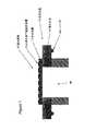
図1に示すように、通気装置40は、気体の流路45と通気要素43を有する通気本体42を備えていてよい。その通気要素43は流路45の気体透過性液密シールを形成することができる。 As shown in FIG. 1, the ventilation device 40 may include a
通気本体42は、差込み部品、キャップ部品または成形部品の形状であってもよい。別の面では、図2に示すように、囲いに、通気本体が組み込まれていてもよい。簡単な形状では、囲いは、多孔質複合体通気材料でシールされた開口を備えていて、通気が行われてもよい。 The
通気本体は、好ましくはポリマー材料で構築され、その結果、多孔質複合体物品を本体にヒートシールすることを含む工程を容易に簡単なものにする。この通気本体は、各種の形状で構築されて、囲いに対していずれの方向に(垂直の、水平のまたは角度をなして傾斜した方向)設置されてもよい。通気本体を囲いに取り付ける手段は、意図する通気用途によって決まる。代表的な取り付け手段としては、締り嵌め、ねじまたは接着剤がある。したがって、通気本体に、突刺、ねじなどを組み入れて取り付けを改善できる。 The vented body is preferably constructed of a polymeric material, so that the process including heat sealing the porous composite article to the body is easily simplified. The ventilation body may be constructed in various shapes and installed in any direction (vertical, horizontal or inclined at an angle) relative to the enclosure. The means for attaching the vent body to the enclosure depends on the intended vent application. Typical attachment means include an interference fit, a screw or an adhesive. Therefore, it is possible to improve attachment by incorporating a piercing, a screw or the like into the ventilation body.
図3に見られるように、その多孔質複合体物品20は、細孔23を有する多孔質膜22、その多孔質膜に取り付けられた非多孔質不連続表面層24および疎油性を付与するコーティング28で構成されていてよい。その非多孔質不連続表面層24は、多孔質膜の細孔23の少なくともいくつかを閉塞するが、気体透過性の領域を提供する離れて分布した開口29を有する。その非多孔質不連続表面層によって、低表面張力の粘性流体に暴露された後の、複合体の空気流回復率が改善される。この多孔質複合体は、その複合体のオイルレイティング(oil rating)が約2より大きくなるようなポリマーコーティング28を適用することによって疎油性にすることができる。 As seen in FIG. 3, the porous
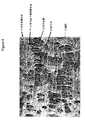
図4〜7は、代表的な多孔質複合体の走査型電子顕微鏡の写真(SEM)である。その多孔質膜22は多数の細孔23を含む構造を有している。その多孔質膜は、その膜を気体透過性にする細孔を有するいかなる多孔質材料であってもよい。多孔質膜としては、限定されないが、ポリエチレン、ポリプロピレン、ポリスルホン、ポリエーテルスルホン、ポリフッ化ビニリデン(PVDF)、酢酸セルロース、ポリカーボネート、超高分子量ポリエチレン(UHMWPE)、および好ましくは延伸PTFEの膜が挙げられる。Goreの米国特許第3,953,566号の教示に従って製造される延伸PTFE膜が特に有用である。これらの多孔質膜は、一軸方向、二軸方向または半径方向に延伸することができる。 4 to 7 are scanning electron microscope photographs (SEM) of representative porous composites. The porous film 22 has a structure including a large number of
非多孔質不連続表面層24は、多孔質膜22に取り付けられて、多孔質膜22の細孔23の少なくともいくつかを、膜の表面において閉鎖する不連続表面を提供することができ、その結果、その多孔質複合体の表面は、気体透過性の領域と気体不透過性の領域を有している。非多孔質不連続表面層24は、限定されないが、熱可塑性材料、熱硬化性材料およびエラストマー材料を含む広範囲の材料で作ることができる。熱可塑性材料が好ましく、熱可塑性材料としては、限定されないが、ポリエステル、ポリエチレン、ポリプロピレン、フッ化ビニリデン、テトラフルオロエチレン/ヘキサフルオロプロピレンのコポリマー(FEP)、テトラフルオロエチレン/ペルフルオロアルキルビニルエーテルのコポリマー(PFA)、クロロトリフルオロエチレン(CTFE)、およびTHV(テトラフルオロエチレン、ヘキサフルオロプロピレン、フッ化ビニリデンのポリマー)が挙げられる。FEPまたはPFAなどのフッ素化熱可塑性材料が特に好ましい。 A non-porous discontinuous surface layer 24 can be attached to the porous membrane 22 to provide a discontinuous surface that closes at least some of the
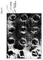
図4と5に示す一実施態様では、非多孔質不連続表面層24は、PTFEテープに積層され次いで同時に延伸されたフッ素化熱可塑性材料である。そのフッ素化熱可塑性材料は、延伸されると、破断して多数の不連続の裂け目26を形成する。図8に示す別の実施態様では、非多孔質不連続表面層24は、小孔25を有する非多孔質被膜27を含んでいる。この孔あき被膜を多孔質膜層に取り付けて、多孔質複合体を形成する。 In one embodiment shown in FIGS. 4 and 5, the non-porous discontinuous surface layer 24 is a fluorinated thermoplastic material that is laminated to PTFE tape and then stretched simultaneously. When stretched, the fluorinated thermoplastic material breaks to form a number of discontinuous tears 26. In another embodiment shown in FIG. 8, the non-porous discontinuous surface layer 24 includes a non-porous coating 27 having small pores 25. The porous coating is attached to the porous membrane layer to form a porous composite.
図7に示す別の実施態様では、非多孔質不連続表面層24は、熱可塑性材料のコーティングを含んでいる。そのコーティングは、多孔質膜22上に開口29を有する非多孔質不連続表面層24を形成している。このコーティングはいくつかの細孔23を閉塞して、多孔質複合体の表面に気体不透過性の領域を生成する。 In another embodiment shown in FIG. 7, non-porous discontinuous surface layer 24 includes a coating of thermoplastic material. The coating forms a non-porous discontinuous surface layer 24 having an
その多孔質複合体は、疎油性にすることができるので、低表面張力の粘性流体に対する耐性を必要とするいくつかの通気用途に利用できる。この用途に使用する場合、用語「疎油性」は、AATCC Test Method 118-2002のオイルレイティングが約2より大きい物品を意味する。例えば、多孔質複合体は、米国特許第5,116,650号に記載されているようなペルフルオロジオキソールポリマーの溶液でコートできる。このコーティングは、多孔質複合体の要素の少なくとも一つに、これら要素を合わせて取り付ける前に適用してもよい。例えば、多孔質膜は、この膜に非多孔質不連続層を取り付けるかまたは適用する前に、コーティング溶液で処理して疎油性を付与することができる。 Because the porous composite can be made oleophobic, it can be utilized in several venting applications that require resistance to low surface tension viscous fluids. As used in this application, the term “oleophobic” means an article having an AATCC Test Method 118-2002 oil rating greater than about 2. For example, the porous composite can be coated with a solution of perfluorodioxole polymer as described in US Pat. No. 5,116,650. This coating may be applied to at least one of the elements of the porous composite prior to attaching these elements together. For example, a porous membrane can be treated with a coating solution to impart oleophobicity prior to attaching or applying a non-porous discontinuous layer to the membrane.
非多孔質表面層は、積層し次いで同時に延伸する方法で形成できる。非多孔質熱可塑性被膜を、PTFEに積層し次いで延伸して、ePTFE膜およびフッ素化熱可塑性材料を含む非多孔質不連続表面層の複合体を形成できる。この方法では、熱可塑性被膜の破断が起こって、図4と5に示すような裂け目26を作ることができる。この熱可塑性材料は、ePTFEとその熱可塑性材料を、熱可塑性材料の溶融温度を超えて加熱したローラーまたはプレートなどの表面を通過させて結合させることによって、ePTFEに積層できる。次に、これら結合させた層を一軸方向、二軸方向または半径方向に延伸して熱可塑性表面に裂け目を形成させることができる。この実施態様におけるポリマーの非多孔質不連続表面層24は、厚さが0.5マイクロメートルと薄くてもよい。好ましい実施態様では、FEPをPTFEに積層し次いでその積層体を延伸して多孔質複合体を形成する。 The non-porous surface layer can be formed by laminating and then stretching simultaneously. A non-porous thermoplastic coating can be laminated to PTFE and then stretched to form a non-porous discontinuous surface layer composite comprising an ePTFE membrane and a fluorinated thermoplastic material. In this way, a break in the thermoplastic coating occurs and a tear 26 as shown in FIGS. 4 and 5 can be created. This thermoplastic material can be laminated to ePTFE by bonding ePTFE and its thermoplastic material through a surface such as a roller or plate heated above the melting temperature of the thermoplastic material. These bonded layers can then be stretched uniaxially, biaxially or radially to form a tear in the thermoplastic surface. The non-porous discontinuous surface layer 24 of polymer in this embodiment may be as thin as 0.5 micrometers. In a preferred embodiment, FEP is laminated to PTFE and the laminate is then stretched to form a porous composite.
図8によれば、非多孔質不連続表面層24は、非多孔質被膜に小孔をあけ次いでそれを多孔質膜に結合させることによって形成することもできる。この好ましい非多孔質不連続表面層はポリマー層であり、FEPまたはPFAなどのフッ素化熱可塑性被膜層を含んでいてもよい。その非多孔質ポリマー被膜層は、限定されないが、機械的穿孔法またはレーザードリリング法を含む従来法を使って小孔をあけることができる。好ましい方法はレーザードリリング法である。次いで、その小孔をあけられた非多孔質不連続表面層は、限定されないが、ホットロール積層法、接着結合法または超音波結合法を含む従来法によって、多孔質膜に取り付けることができる。別の一面では、小孔をあけた非多孔質被膜をPTFEに取り付けて、次に延伸することができる。 According to FIG. 8, the non-porous discontinuous surface layer 24 can also be formed by making small holes in the non-porous coating and then bonding it to the porous membrane. This preferred non-porous discontinuous surface layer is a polymer layer and may include a fluorinated thermoplastic coating layer such as FEP or PFA. The non-porous polymer coating layer can be pierced using conventional methods including, but not limited to, mechanical drilling or laser drilling. A preferred method is laser drilling. The perforated non-porous discontinuous surface layer can then be attached to the porous membrane by conventional methods including, but not limited to, hot roll lamination, adhesive bonding, or ultrasonic bonding. In another aspect, a small porous non-porous coating can be attached to PTFE and then stretched.
図8に示す実施態様では、厚さが12.5マイクロメートルのFEPシートに、Universal Laser Systems Inc.(米国アリゾナ州スコッツデール所在)の50 Wのレーザー機械を使用して小孔をあけた。その小孔25は直径が0.76 mmで、その小孔の中心間距離は1.02 mmであった。次いで、その小孔をあけたFEP層を、多孔質ePTFE膜に結合させて多孔質複合体を形成できる。 In the embodiment shown in FIG. 8, a 12.5 micrometer thick FEP sheet was pierced using a 50 W laser machine from Universal Laser Systems Inc. (Scottsdale, Arizona, USA). The small hole 25 had a diameter of 0.76 mm, and the distance between the centers of the small holes was 1.02 mm. The FEP layer with the small holes can then be bonded to a porous ePTFE membrane to form a porous composite.
形状または製造方法の如何にかかわらず、上記非多孔質不連続表面層は、多孔質膜層の上に表面を形成し、多孔質膜の細孔のいくつかが閉塞される。したがって、その非多孔質不連続表面層は開口付きの不連続表面を有し、その結果、多孔質複合体は気体透過性の領域と気体不透過性の領域を有する。非多孔質不連続表面層の開口の大きさと形状は様々に変えることができる。 Regardless of shape or manufacturing method, the non-porous discontinuous surface layer forms a surface on the porous membrane layer, and some of the pores of the porous membrane are occluded. The non-porous discontinuous surface layer thus has a discontinuous surface with openings, so that the porous composite has a gas permeable region and a gas impermeable region. The size and shape of the openings in the non-porous discontinuous surface layer can be varied.
多孔質複合体物品は、通気囲いの通気要素として使用できる。その通気要素は、液体を入れるかまたは除くため、囲いに液密シールを形成するのに有利に使用できる。この通気要素は、気体の膨張、化学薬剤の脱ガスなどのために必要な気体透過性を提供する。図2に示すように、通気装置40は、液体暴露側41とその反対側47を有するように構築することができる。非多孔質不連続表面層24は、多孔質膜22の上に配置されて、多孔質複合体20の液体暴露側41を形成してもよい。その液体暴露側41は、液体38が入っている囲い32の内部に向けることができる。液体が入っているこれらの用途(例えば液体洗剤の容器)では、その多孔質複合体は気体透過性を提供する。その気体透過性によって、熱サイクルが原因の囲いの変形または破裂を防止でき、あるいは液体の脱ガスを実施できる。液体の侵入を防止しなければならない図10に示す別の実施態様では、液体暴露側41は、囲い32の外側に向けることができる。反対側47は、囲いの内側に向いている。かような用途(例えば電子機器の囲いまたは照明の囲い)では、多孔質複合体は、液体が囲いに侵入するのを防ぎながら気体透過性を提供できる。図9に図式的に示すさらに別の構造では、多孔質複合体の両側を、液体暴露側として構築することができる。 The porous composite article can be used as a vent element for a vent enclosure. The venting element can be advantageously used to form a liquid tight seal on the enclosure to contain or remove liquid. This vent element provides the necessary gas permeability for gas expansion, chemical agent degassing, and the like. As shown in FIG. 2, the venting device 40 can be constructed to have a liquid exposed side 41 and its
好ましくは、液体暴露側の空気流回復率は、反対側の空気流回復率より少なくとも1.1%高い。より好ましくは、液体暴露側の空気流回復率は、反対側の空気流回復率より少なくとも5%高い。多孔質複合体が二つの液体暴露側を有している実施態様では、多孔質複合体の空気流回復率は、多孔質膜単独の空気流回復率より少なくとも約5%高いことが好ましい。 Preferably, the air flow recovery rate on the liquid exposed side is at least 1.1% higher than the air flow recovery rate on the opposite side. More preferably, the air flow recovery rate on the liquid exposed side is at least 5% higher than the air flow recovery rate on the opposite side. In embodiments in which the porous composite has two liquid exposed sides, the air flow recovery rate of the porous composite is preferably at least about 5% higher than the air flow recovery rate of the porous membrane alone.
一実施態様では、多孔質疎油性複合体の空気流回復率は、複合体の液体暴露側が低表面張力の粘性流体に暴露されたときに少なくとも約33%とすることができる。この複合体の空気流回復率は、反対側が同じ低表面張力の粘性流体に暴露されたときに0%である。より好ましくは、多孔質複合体の空気流回復率は、その液体暴露側が低表面張力の粘性流体に暴露されたときに少なくとも約50%である。この複合体の空気流回復率は、反対側が同じ低表面張力の粘性流体に暴露されたときに0%である。 In one embodiment, the air flow recovery rate of the porous oleophobic composite can be at least about 33% when the liquid exposed side of the composite is exposed to a low surface tension viscous fluid. The airflow recovery rate of this composite is 0% when the opposite side is exposed to the same low surface tension viscous fluid. More preferably, the air flow recovery rate of the porous composite is at least about 50% when its liquid exposed side is exposed to a low surface tension viscous fluid. The airflow recovery rate of this composite is 0% when the opposite side is exposed to the same low surface tension viscous fluid.
別の実施態様では、多孔質複合体の空気流回復率は、その液体暴露側が低表面張力の粘性流体に暴露されたときに4%である。多孔質複合体の空気流回復率は、反対側が同じ低表面張力の粘性流体に暴露されたときに0.4%である。より好ましくは、多孔質複合体の空気流回復率は、その複合体の液体暴露側が低表面張力の粘性流体に暴露されたときに12%である。多孔質複合体の空気流回復率は、反対側が同じ低表面張力の粘性流体に暴露されたときに0.1%である。 In another embodiment, the air flow recovery rate of the porous composite is 4% when its liquid exposed side is exposed to a low surface tension viscous fluid. The air flow recovery rate of the porous composite is 0.4% when the opposite side is exposed to the same low surface tension viscous fluid. More preferably, the air flow recovery rate of the porous composite is 12% when the liquid exposed side of the composite is exposed to a low surface tension viscous fluid. The air flow recovery rate of the porous composite is 0.1% when the opposite side is exposed to the same low surface tension viscous fluid.
多孔質複合体は積層体として構築できる。その積層体は、図3に示すように、多孔質複合体20を支持層30の上に支持することによって、製造することができる。支持層30は、図10に示すように、構造を支持しており、さらに、多孔質複合体20を通気囲い32に取り付けるのにも役立つ場合もある。適切な支持層は、編物、不織布、スクリム、メルトブローン、織布、メッシュ、フォーム、多孔質ePTFE膜などの空気透過性媒体の形態であってよい。支持層は、例えば、ホットロール積層法、接着剤または超音波接合法によって、多孔質複合体に取り付けることができる。支持層は、多孔質複合体の両面に取り付けることもできる。 The porous composite can be constructed as a laminate. The laminate can be manufactured by supporting the porous composite 20 on a support layer 30 as shown in FIG. The support layer 30 supports the structure as shown in FIG. 10 and may also serve to attach the porous composite 20 to the vent enclosure 32. Suitable support layers may be in the form of air permeable media such as knitted fabrics, nonwoven fabrics, scrims, meltblowns, woven fabrics, meshes, foams, porous ePTFE membranes and the like. The support layer can be attached to the porous composite by, for example, a hot roll lamination method, an adhesive, or an ultrasonic bonding method. The support layer can also be attached to both sides of the porous composite.
本発明を、さらに、下記の非限定の諸実施例について説明する。 The invention is further described in the following non-limiting examples.
試験方法
密度
2.54 cm×15.24 cmの長方形断片に打ち抜いた試料の質量(Mettler-Toledo analytical balance model AG204を使用)と厚さ(Kafer FZ1000/30 snap guageを使用)を測定した。これらのデータを利用し、下記式で密度を計算した。
ρ=m/(w×l×t)
上記式中、ρ=密度(g/cc);m=質量(g);w=幅(cm);l=長さ(cm);およびt=厚さ(cm)である。Test method density
The mass (using Mettler-Toledo analytical balance model AG204) and thickness (using Kafer FZ1000 / 30 snap guage) of a specimen punched into a 2.54 cm × 15.24 cm rectangular piece were measured. Using these data, the density was calculated by the following formula.
ρ = m / (w × l × t)
In the above formula, ρ = density (g / cc); m = mass (g); w = width (cm); l = length (cm); and t = thickness (cm).
多孔率
多孔率は、百分率で表現し、物品の密度(先に記載)をPTFEのかさ密度で割り算して得た商を1から引き算し、その値に100%を掛け算することによって決定した。この計算を行うため、PTFEのかさ密度を2.2 g/ccにした。Porosity Porosity was expressed as a percentage and was determined by subtracting the quotient obtained by dividing the article density (described above) by the bulk density of PTFE from 1 and multiplying that value by 100%. For this calculation, the bulk density of PTFE was 2.2 g / cc.
空気流回復率
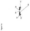
図11と11aは空気流回復率の試験に使用する装置を示す。通気材料100を、上プレート102と下プレート104の間に封止する。各プレートは、直径2.54 cmのオリフィスを有している。上プレートには、液体ウエル106が組み込まれている。通気材料100は、ガスケット108とちょうねじ110を使って、これらプレート間に固定する。次に、上記組み付けたプレートを、アダプター300に、クランプ302、ちょうねじ304およびガスケット306によって固定する。アダプター300は、空気チャンバー301とこのチャンバーに空気を送るチャネル310を備えている。Telydyne Genuine Gurley(商標)tester(Model Number 4110)を、アダプター300の入口312に、ガスケット308を使って取り付ける。Airflow recovery rate Figures 11 and 11a show the equipment used to test the airflow recovery rate. The
試料に、100 cm3の空気を、水圧12.4 cmで送り、流動時間を秒で記録する。この測定値は、流体が接触する前のガーレイ数(秒)である。The sample is fed with 100 cm3 of air at a water pressure of 12.4 cm and the flow time is recorded in seconds. This measured value is the number of Gurley (seconds) before the fluid contacts.
次いで、プレートをアダプターから取り外し、次にその通気材料の全表面が試験流体で覆われるように液体ウエル106を満たすことによって、試験流体に暴露させる。これは、全量ピペットを使って、試験流体約2〜3 cm3をウエル106に添加することによって実施できる。60秒後、そのプレート組立て物を、90°傾ける。通気材料から、液体を60秒間排出させる。次にそのプレートをTelydyne Genuine Gurley(商標)tester(Model Number 4110)に取り付けられているアダプター300に固定する。The plate is then removed from the adapter and then exposed to the test fluid by filling the liquid well 106 so that the entire surface of the vent material is covered with the test fluid. This can be done by adding approximately 2-3 cm3 of test fluid to well 106 using a full volume pipette. After 60 seconds, the plate assembly is tilted 90 °. Allow liquid to drain from vent material for 60 seconds. The plate is then secured to an
100 cm3の空気を、試料を通じて水圧12.4 cmで流動させて、流動時間を秒で記録する。この測定値は流体が接触した後のガーレイ数(秒)である。この試験で10分後に空気の流動が始まらなかった場合は、試験を中止して、試料は回復しないとみなし空気流動が回復しないとしてNRで表す。次いで、空気流回復率を、下記式を使って決定する。
空気流回復率(%)=[流体が接触する前のガーレイ数(秒)
/流体が接触した後のガーレイ数(秒)]×100100 cm3 of air is flowed through the sample at a water pressure of 12.4 cm and the flow time is recorded in seconds. This measured value is the number of Gurley (seconds) after fluid contact. If air flow does not start after 10 minutes in this test, the test is discontinued and the sample is considered not to recover and is expressed as NR as air flow does not recover. The air flow recovery rate is then determined using the following formula:
Airflow recovery rate (%) = [Gurley number before fluid contact (seconds)
/ Gurley number after contact with fluid (seconds)] × 100
水浸入圧
用語「水浸入圧」は、本願で使用する場合、本明細書に含まれている試験法に記載されているように、膜などの材料を通じて水を移動させるのに必要な圧力を意味する。水侵入圧は、膜または通気本体を通過する水の浸入の試験方法を提供する。膜(または通気本体)を、器具の中に入れて水で加圧する。加圧されてない側の膜(または通気本体)の頂部に、一枚のpH試験紙を、水浸入の証拠を示すものとして配置してもよい。次いで試料をpH試験紙の色の変化が水浸入の最初の兆候を示すまで少しずつ圧力を増やしながら加圧する。漏出時すなわち侵入時の水圧を、水浸入圧として記録する。Water intrusion pressure The term “water intrusion pressure” as used herein refers to the pressure required to move water through a material, such as a membrane, as described in the test methods contained herein. means. Water intrusion pressure provides a test method for water ingress through a membrane or vent body. The membrane (or vent body) is placed in the instrument and pressurized with water. A sheet of pH test paper may be placed on top of the non-pressurized membrane (or vent body) as evidence of water ingress. The sample is then pressurized with increasing pressure until the change in pH test paper color shows the first sign of water ingress. Record the water pressure at the time of leakage or entry as the water intrusion pressure.
バブルポイント
バブルポイントと平均流動孔サイズは、Capillary Flow Porometer(米国ニューヨーク州イサカ所在のPorous Materials Inc.のModel CFP 1500 AEXL)を使用して、ASTM F31 6-03の一般的教示に従って測定した。試料の膜を、試料チャンバー内に入れて、表面張力が19.1ダイン/cmのSilWick Silicone Fluid(Porous Materials Inc.から入手できる)で濡らした。試料チャンバーの下部クランプは、直径が2.54 cm、厚さが3.175 mmの多孔質金属ディスクインサート(米国コネティカット州ファーミントン所在のMott Metallurgical、40マイクロメートル多孔質金属ディスク)を有し、そして試料チャンバーの上部クランプには直径が3.175 mmの穴があった。Capwin software version 6.62.1を使用して、下記パラメータを、下記表に記載したように設定した。バブルポイントおよび平均流動細孔サイズとして示された値は、二つの測定値の平均値である。Bubble Point Bubble points and average flow pore size were measured using a Capillary Flow Porometer (Model CFP 1500 AEXL from Porous Materials Inc., Ithaca, NY, USA) according to the general teachings of ASTM F31 6-03. The sample film was placed in the sample chamber and wetted with SilWick Silicone Fluid (available from Porous Materials Inc.) with a surface tension of 19.1 dynes / cm. The lower clamp of the sample chamber has a porous metal disc insert (Mott Metallurgical, Farmington, Connecticut, 40 micrometer porous metal disc) 2.54 cm in diameter and 3.175 mm in thickness, and the sample chamber The upper clamp had a hole with a diameter of 3.175 mm. Using Capwin software version 6.62.1, the following parameters were set as described in the table below. The values given as bubble point and average flow pore size are the average of the two measurements.

オイルレイティング
オイルレイティングの試験を、AATCC Test Method 118-2002に従って実施した。膜のオイルレイティング値は、膜の両面を試験して得た二つのレイティング値のうち小さい方である。Oil Rating The oil rating test was performed according to AATCC Test Method 118-2002. The oil rating value of the membrane is the smaller of the two rating values obtained by testing both sides of the membrane.
表面張力
被検流体の表面張力は、Whilhelmy plate methodを利用し、Kruss K12 tensiometerを使って測定した。Kruss Laboratory Desktop Software Version 2.13aを使用した。Whilhelmy plateの浸漬は、火炎処理ガラスのカバースリップ(flamed glass cover slips)を用いソフトウェアの初期設定の浸漬パラメータで実施した。Surface tension The surface tension of the test fluid was measured using the Kruss K12 tensiometer using the Whilhelmy plate method. Kruss Laboratory Desktop Software Version 2.13a was used. Whilhelmy plate immersion was performed using flame treated glass cover slips with the software default immersion parameters.
粘度
粘度はUL小容積スピンドルとチューブアクセサリー付きのBrookfield DVII+viscometerを使って測定した。温度22.5℃、30 RPMおよびせん断速度36.7 second-1における粘度を、センチポワズ(cp)の単位で報告してある。トルクで許容される最大RPMで予め回転させた試料を30 RPMで5分間回転させた後に、粘度を読み取った。Viscosity Viscosity was measured using a Brookfield DVII + viscometer with a UL small volume spindle and tube accessory. The viscosity at a temperature of 22.5 ° C., 30 RPM and a shear rate of 36.7 second−1 is reported in units of centipoise (cp). The sample was pre-rotated at the maximum RPM allowed by torque and rotated for 5 minutes at 30 RPM before reading the viscosity.
被検流体
二つの代表的な被検流体を配合し、流体暴露後の空気流回復率の試験に利用した。これら流体の特性は下記表に列挙してある。被検流体Iは、オイルレイティング値が約2より大きい疎油性物品に使用した。被検流体IIは、疎水性物品に使用した。Test fluids Two typical test fluids were blended and used to test the air flow recovery rate after fluid exposure. The properties of these fluids are listed in the table below. Test fluid I was used for an oleophobic article having an oil rating value greater than about 2. Test fluid II was used for hydrophobic articles.
被検流体Iは下記方法で調製した。
PVP(ポリビニルピロリドン、Sigma-Aldrich Chemical, Catalog Number 437190-500G, 分子量=1,300,000, CAS Number 9003-39-8)を脱イオン水に溶解した溶液を、これら成分を混合し、一夜、撹拌することによって調製した。Tergitol(登録商標)TMN6(Dow Chemical, CAS Number 60828-78-6)を添加し、その溶液を約1時間撹拌した後、直ちに試験に使用した。Test fluid I was prepared by the following method.
A solution of PVP (polyvinylpyrrolidone, Sigma-Aldrich Chemical, Catalog Number 437190-500G, molecular weight = 1,300,000, CAS Number 9003-39-8) in deionized water is mixed with these ingredients and stirred overnight. Prepared. Tergitol® TMN6 (Dow Chemical, CAS Number 60828-78-6) was added and the solution was stirred for about 1 hour before being used for testing.
被検流体IIは下記方法で調製した。
Tween(登録商標)(Mallinckrodt Baker, Inc., Catalog Number X257-07, CAS number 9005-65-6)を脱イオン水に溶解した溶液を、これら2成分を混合して一夜撹拌することによって調製した。グリセリン(Ultra Pure Grade, MP Biomedicals, Catalog Number 800688)を添加し、その溶液を約1時間撹拌した後、直ちに試験に使用した。Test fluid II was prepared by the following method.
A solution of Tween® (Mallinckrodt Baker, Inc., Catalog Number X257-07, CAS number 9005-65-6) in deionized water was prepared by mixing these two components and stirring overnight. . Glycerin (Ultra Pure Grade, MP Biomedicals, Catalog Number 800688) was added and the solution was stirred for about 1 hour before being used for testing immediately.
例1
PTFEポリマーの微粉末(米国ニューヨーク州オレンジバーグ所在のDaikin Industries, Ltd.)を、この微粉末1 g当たり0.25 gの比率のIsopar K(米国バージニア州フェアファックス所在のExxon Mobil Corp.)と混合した。その潤滑にされた粉末をシリンダー中に圧入してペレットを製造し、25℃に設定したオーブン中に約24時間入れた。圧縮され加熱されたペレットをラム押出しして、幅が約29 cmで厚さが0.635 mmのテープを製造した。次いでそのテープを、圧縮ロール間で圧延して厚さ0.20 mmにした。次いでそのテープを、250℃に設定したオーブン内で乾燥した。その乾燥PTFEテープと厚さ12.5μmのFEPフィルムを重ねて、300℃の温度に設定した二つの加熱プレート上のロールのバンク間で縦方向に延伸した。ロールの第二バンクとロールの第一バンクの間の速度比、したがって、第一プレート上の延伸比は1.15:1であった。ロールの第三バンクとロールの第二バンクの間の速度比、したがって第二プレート上の延伸比は1.15:1であった。次に、そのFEPを積層されたPTFEの複合体テープを、320℃の温度に設定された熱風オーブンに通して、5:1の比率で縦方向に延伸した。PTFEテープに結合されたFEPフィルムは、溶融してその二つの層が延伸されると、FEPフィルムに裂け目が生成した。次に、その縦方向に延伸された複合体を、360℃の温度に設定された熱風オーブンに通して熱処理した。次いで、その複合体を、約370℃の温度で横方向に、約7:1の比率で延伸し、次に、370℃に設定したオーブン中に約24秒間滞留させて熱処理した。Example 1
PTFE polymer fine powder (Daikin Industries, Ltd., Orangeburg, NY, USA) was mixed with Isopar K (Exxon Mobil Corp., Fairfax, VA) at a ratio of 0.25 g / g of this fine powder. . The lubricated powder was pressed into a cylinder to produce pellets and placed in an oven set at 25 ° C. for about 24 hours. The compressed and heated pellets were ram extruded to produce a tape approximately 29 cm wide and 0.635 mm thick. The tape was then rolled between compression rolls to a thickness of 0.20 mm. The tape was then dried in an oven set at 250 ° C. The dried PTFE tape and a 12.5 μm thick FEP film were overlaid and stretched longitudinally between banks of rolls on two heating plates set at a temperature of 300 ° C. The speed ratio between the second bank of rolls and the first bank of rolls, and thus the draw ratio on the first plate, was 1.15: 1. The speed ratio between the third bank of rolls and the second bank of rolls, and thus the draw ratio on the second plate, was 1.15: 1. Next, the composite tape of PTFE laminated with the FEP was passed through a hot air oven set at a temperature of 320 ° C. and stretched in the machine direction at a ratio of 5: 1. When the FEP film bonded to PTFE tape was melted and the two layers were stretched, a tear formed in the FEP film. Next, the composite stretched in the longitudinal direction was heat-treated through a hot air oven set at a temperature of 360 ° C. The composite was then stretched in the transverse direction at a temperature of about 370 ° C. at a ratio of about 7: 1 and then heat treated by staying in an oven set at 370 ° C. for about 24 seconds.
このようにして製造した多孔質複合体は、バブルポイントが6.9 psiであった。この複合体の両面の、被検流体IIに対する空気流回復率を試験した。試験結果を表Iに示す。 The porous composite produced in this way had a bubble point of 6.9 psi. The air flow recovery rate for the test fluid II on both sides of the composite was tested. The test results are shown in Table I.
上記複合体を、下記手順に従って処理して疎油性にした。0.25質量%のTeflon(登録商標) AF 1600(米国デラウエア州ウイルミントン所在のDupont Fluoroproducts)をPF-5070 Brand Performance Fluid(CAS Number 86508-42-1, 3M)に添加し、その流体を一夜混合することによって、溶液を調製した。複合体の試料を、丸枠(直径15.2 cm)にぴんと張って保持した。次に、ピペットを使って、上記溶液5〜6 cm3を、複合体試料の液体暴露側に塗布した。複合体試料を傾斜させ回転させて、前記溶液を試料に完全に飽和させた。この時点で、試料は透明になり、全体が濡れて見えた。その丸枠を、直ちにフード中に垂直に吊り下げて、一夜乾燥させた。次に、その疎油性複合体の両面の空気流回復率を、被検流体Iを使って試験した。得られた試験結果を表Iに示す。オイルレイティングの測定値は5であった。The composite was treated to make it oleophobic according to the following procedure. Add 0.25 wt% Teflon AF 1600 (Dupont Fluoroproducts, Wilmington, Del.) To PF-5070 Brand Performance Fluid (CAS Number 86508-42-1, 3M) and mix the fluid overnight A solution was prepared. A sample of the composite was held tightly on a round frame (15.2 cm diameter). Next, using a pipette, 5-6 cm3 of the above solution was applied to the liquid exposed side of the composite sample. The composite sample was tilted and rotated to fully saturate the solution to the sample. At this point, the sample became clear and the whole looked wet. The round frame was immediately suspended vertically in the hood and allowed to dry overnight. Next, the air flow recovery rate on both sides of the oleophobic composite was tested using test fluid I. The test results obtained are shown in Table I. The measured oil rating was 5.
例2
PTFEポリマーの微粉末(米国ニューヨーク州オレンジバーグ所在のDaikin Industries, Ltd.)を、この微粉末1 g当たり0.196 gの比率のIsopar K(米国バージニア州フェアファックス所在のExxon Mobil Corp.)と混合した。その潤滑にされた粉末をシリンダー中に圧入してペレットを製造して、70℃に設定したオーブン中に約12時間入れた。圧縮され加熱されたペレットをラム押出しして、幅が約15.2 cmで厚さが0. 73 mmのテープを製造した。テープの別個の二つのロールを作製し、これらテープを圧縮ロール間で重ねて厚さ0.254 mmにした。そのテープを、次に、横方向に56 cm(すなわち3.7:1の比率で)延伸し、次いで250℃に設定したオーブン中で乾燥した。その乾燥したテープを、温度340℃に設定した加熱プレート上のロールのバンク間で縦方向に延伸した。前記PTFEテープに厚さ12.5マイクロメートルのFEPフィルムを重ねた後に、上記プレート上で延伸した。ロールの第二バンクとロールの第一バンクの間の速度比、したがって延伸比は14:1であった。PTFEテープに結合させたFEPフィルムを溶融させて二つの層を延伸すると、FEPフィルムに裂け目が生成した。この縦方向に延伸された複合体を、次に、約350℃の温度にて、約20:1の比率で横方向に延伸し、次いで380℃に設定したオーブン中で約24秒間滞留させて加熱した。Example 2
A fine powder of PTFE polymer (Daikin Industries, Ltd., Orangeburg, NY, USA) was mixed with Isopar K (Exxon Mobil Corp., Fairfax, VA) at a ratio of 0.196 g / g of this fine powder. . The lubricated powder was pressed into a cylinder to produce pellets and placed in an oven set at 70 ° C. for about 12 hours. The compressed and heated pellets were ram extruded to produce a tape having a width of about 15.2 cm and a thickness of 0.73 mm. Two separate rolls of tape were made and the tapes were overlapped between the compression rolls to a thickness of 0.254 mm. The tape was then stretched 56 cm laterally (i.e. in a 3.7: 1 ratio) and then dried in an oven set at 250 ° C. The dried tape was stretched longitudinally between banks of rolls on a heating plate set at a temperature of 340 ° C. A 12.5 micrometer thick FEP film was overlaid on the PTFE tape and then stretched on the plate. The speed ratio between the second bank of rolls and the first bank of rolls, and thus the draw ratio, was 14: 1. When the FEP film bonded to PTFE tape was melted and the two layers were stretched, a tear was formed in the FEP film. This longitudinally stretched composite is then stretched transversely at a ratio of about 20: 1 at a temperature of about 350 ° C. and then allowed to stay in an oven set at 380 ° C. for about 24 seconds. Heated.
このようにして、製造した多孔質複合体は、バブルポイントが30 psiであった。その複合体の両面について、被検流体IIに対する空気流回復率を試験した。試験結果を表IIに示す。 In this way, the produced porous composite had a bubble point of 30 psi. The air flow recovery rate for the fluid to be tested II was tested on both sides of the composite. The test results are shown in Table II.
上記複合体を、以下の手順に従って処理して疎油性にした。0.25質量%のTeflon(登録商標) AF 1600(米国デラウエア州ウイルミントン所在のDupont Fluoroproducts)をPF-5070 Brand Performance Fluid(CAS Number 86508-42-1, 3M)に添加し、その流体を一夜混合することによって、溶液を調製した。複合体の試料を、丸枠(直径15.2 cm)にぴんと張って保持した。次に、ピペットを使って、上記溶液5〜6 cm3を、複合体試料の液体暴露側に塗布した。複合体試料を傾斜させ回転させて、前記溶液を試料に完全に飽和させた。この時点で、試料は透明になり、全体が濡れて見えた。その丸枠を、直ちにフード中に垂直に吊り下げて、一夜乾燥させた。次に、その疎油性複合体の両面の空気流回復率を、被検流体Iを使って試験した。得られた試験結果を表IIに示す。オイルレイティングの測定値は6であった。The composite was treated to make it oleophobic according to the following procedure. Add 0.25 wt% Teflon AF 1600 (Dupont Fluoroproducts, Wilmington, Del.) To PF-5070 Brand Performance Fluid (CAS Number 86508-42-1, 3M) and mix the fluid overnight A solution was prepared. A sample of the composite was held tightly on a round frame (15.2 cm diameter). Next, using a pipette, 5-6 cm3 of the above solution was applied to the liquid exposed side of the composite sample. The composite sample was tilted and rotated to fully saturate the solution to the sample. At this point, the sample became clear and the whole looked wet. The round frame was immediately suspended vertically in the hood and allowed to dry overnight. Next, the air flow recovery rate on both sides of the oleophobic composite was tested using test fluid I. The test results obtained are shown in Table II. The measured oil rating was 6.
例3
PTFEポリマーの微粉末(米国ニューヨーク州オレンジバーグ所在のDaikin Industries, Ltd.)を、この微粉末1 g当たり0.25 gの比率のIsopar K(米国バージニア州フェアファックス所在のExxon Mobil Corp.)と混合した。その潤滑にされた粉末をシリンダー中に圧入してペレットを製造し、25℃に設定したオーブン中に約24時間入れた。圧縮され加熱されたペレットをラム押出しして、幅が約29 cmで厚さが0. 635 mmのテープを製造した。次いでそのテープを、圧縮ロール間で圧延して厚さ0.20 mmにした。次いでそのテープを、250℃に設定したオーブン内で乾燥した。その乾燥PTFEテープと厚さ12.5μmのPFAフィルムを重ねて、320℃の温度に設定した二つの加熱プレート上のロールのバンク間で縦方向に延伸した。ロールの第二バンクとロールの第一バンクの間の速度比、したがって第一プレート上の延伸比は1.15:1であった。ロールの第三バンクとロールの第二バンクの間の速度比、したがって第二プレート上の延伸比は1.15:1であった。次に、そのPFA/PTFEテープ積層体を320℃の温度に設定された熱風オーブンに通して、8:1の比率で縦方向に延伸した。次に、その縦方向に延伸された複合体を、360℃の温度に設定された熱風オーブンに通して熱処理した。その複合体を、次いで、約380℃の温度で横方向に、約2.4:1の比率で延伸し、次に、380℃に設定したオーブン中に約24秒間滞留させて熱処理した。Example 3
PTFE polymer fine powder (Daikin Industries, Ltd., Orangeburg, NY, USA) was mixed with Isopar K (Exxon Mobil Corp., Fairfax, VA) at a ratio of 0.25 g / g of this fine powder. . The lubricated powder was pressed into a cylinder to produce pellets and placed in an oven set at 25 ° C. for about 24 hours. The compressed and heated pellets were ram extruded to produce a tape having a width of about 29 cm and a thickness of 0.635 mm. The tape was then rolled between compression rolls to a thickness of 0.20 mm. The tape was then dried in an oven set at 250 ° C. The dried PTFE tape and a 12.5 μm thick PFA film were overlaid and stretched longitudinally between banks of rolls on two heating plates set at a temperature of 320 ° C. The speed ratio between the second bank of rolls and the first bank of rolls, and thus the draw ratio on the first plate, was 1.15: 1. The speed ratio between the third bank of rolls and the second bank of rolls, and thus the draw ratio on the second plate, was 1.15: 1. Next, the PFA / PTFE tape laminate was passed through a hot air oven set at a temperature of 320 ° C. and stretched in the longitudinal direction at a ratio of 8: 1. Next, the composite stretched in the longitudinal direction was heat-treated through a hot air oven set at a temperature of 360 ° C. The composite was then stretched in the transverse direction at a temperature of about 380 ° C. at a ratio of about 2.4: 1 and then heat treated by dwelling in an oven set at 380 ° C. for about 24 seconds.
このようにして製造した多孔質複合体は、バブルポイントが0.5 psiであった。この複合体の両面の、被検流体IIに対する空気流回復率を試験した。試験結果を表III に示す。 The porous composite produced in this way had a bubble point of 0.5 psi. The air flow recovery rate for the test fluid II on both sides of the composite was tested. The test results are shown in Table III.
上記複合体を、下記手順に従って処理して疎油性にした。0.25質量%のTeflon(登録商標) AF 1600(米国デラウエア州ウイルミントン所在のDupont Fluoroproducts)をPF-5070 Brand Performance Fluid(CAS Number 86508-42-1, 3M)に添加し、その流体を一夜混合することによって、溶液を調製した。前記複合体の試料を、丸枠(直径15.2 cm)にぴんと張って保持した。次に、ピペットを使って、上記溶液5〜6 cm3を、複合体試料の表面の液体暴露側に塗布した。その複合体試料を傾斜させ回転させて、前記溶液を試料に完全に飽和させた。この時点で、試料は透明になり、全体が濡れて見えた。その丸枠を、直ちにフード中に垂直に吊り下げて、一夜乾燥させた。次に、その疎油性複合体の両面の被検流体Iに対する空気流回復率を検査した。得られた試験結果を表III に示す。オイルレイティングの測定値は6であった。The composite was treated to make it oleophobic according to the following procedure. Add 0.25 wt% Teflon AF 1600 (Dupont Fluoroproducts, Wilmington, Del.) To PF-5070 Brand Performance Fluid (CAS Number 86508-42-1, 3M) and mix the fluid overnight A solution was prepared. A sample of the composite was held tightly on a round frame (diameter 15.2 cm). Next, using a pipette, 5-6 cm3 of the above solution was applied to the liquid exposed side of the surface of the composite sample. The composite sample was tilted and rotated to fully saturate the solution to the sample. At this point, the sample became clear and the whole looked wet. The round frame was immediately suspended vertically in the hood and allowed to dry overnight. Next, the air flow recovery rate for the test fluid I on both sides of the oleophobic composite was examined. The test results obtained are shown in Table III. The measured oil rating was 6.
例4
厚さ12.5マイクロメートルのFEPシートに、Universal Laser Systems Inc.(米国アリゾナ州スコッツデール所在)由来の50 Wレーザー機を使って小孔をあけた。その小孔の大きさは直径0.76 mmで、小孔の中心間距離は1.02 mmであった。この小孔をあけたFEPシートを、ePTFE膜(厚さ22.8マイクロメートル、密度0.39 g/cm3およびバブルポイント8 psi)に、コポリエステルのウエブ(Spunfab, Inc., Product Number PE2900-0.6-45W)を接着剤層として使用し積層した。これらの材料は、次の条件すなわち160℃、60 psi、3秒間をで、ヒートプレス(米国マサチューセッツ州所在のGeo. Knight & Co.)内で積層した。この複合体について、被検流体IIを使って空気流回復率を評価した。試験結果を表IVに示す。Example 4
Small holes were drilled in a 12.5 micrometer thick FEP sheet using a 50 W laser machine from Universal Laser Systems Inc. (Scottsdale, Arizona, USA). The size of the small hole was 0.76 mm in diameter, and the distance between the centers of the small holes was 1.02 mm. This perforated FEP sheet was placed on an ePTFE membrane (thickness 22.8 micrometers, density 0.39 g / cm3 and bubble point 8 psi) on a copolyester web (Spunfab, Inc., Product Number PE2900-0.6-45W ) As an adhesive layer. These materials were laminated in a heat press (Geo. Knight & Co., Massachusetts, USA) under the following conditions: 160 ° C., 60 psi, 3 seconds. About this composite_body | complex, the fluid recovery rate was evaluated using the test fluid II. The test results are shown in Table IV.
例5
5 gのFEP粉末(DuPontのProduct Number 532-8000)を、47.5 gの2-プロパノール(IPA)と47.5 gのHFE-7500(3M NOVEC(商標)Engineered Fluid)の混合物に添加した。その分散液を、透明溶液が生成するまで、数時間撹拌した。厚さ106マイクロメートル、多孔率64%および密度0.78 g/ccのePTFE膜を、連続浸漬コーティング法を利用して、上記溶液でコートした。この工程において、前記ePTFE膜を、第一ローラーに通し、次に第二浸漬ローラーを使って、前記コーティング溶液が入っている浴に通した。このコーティングステップの後、その膜を換気フード内で、室温にて4時間乾燥した。その膜の表面にFEP粒子の薄い層を乗せた。その粒子を溶融させるため、そのコートされた膜をテンターフレーム(tenter frame)に固定して、温度320℃の焼結オーブン中に5分間入れた。このようにして製造された多孔質複合体は、図7に示すような非多孔質不連続表面層を備えていた。溶媒PF-5070(CAS Number 86508-42-1, 3M)に0.75質量%のTeflon(登録商標) AF 1600(DuPont Fluoroproducts、米国デラウエア州ウイルミントン所在)を溶解して得た溶液でコートすることによって、上記多孔質複合体を疎油性にし、次いで換気フード内で室温にて6時間乾燥した。Example 5
5 g FEP powder (DuPont Product Number 532-8000) was added to a mixture of 47.5 g 2-propanol (IPA) and 47.5 g HFE-7500 (3M NOVEC ™ Engineered Fluid). The dispersion was stirred for several hours until a clear solution was formed. An ePTFE membrane having a thickness of 106 micrometers, porosity of 64% and density of 0.78 g / cc was coated with the above solution using a continuous dip coating method. In this step, the ePTFE membrane was passed through a first roller and then through a bath containing the coating solution using a second dip roller. After this coating step, the membrane was dried in a fume hood for 4 hours at room temperature. A thin layer of FEP particles was placed on the surface of the membrane. In order to melt the particles, the coated membrane was fixed to a tenter frame and placed in a sintering oven at a temperature of 320 ° C. for 5 minutes. The porous composite produced in this way had a non-porous discontinuous surface layer as shown in FIG. By coating PF-5070 (CAS Number 86508-42-1, 3M) with a solution obtained by dissolving 0.75 wt% Teflon® AF 1600 (DuPont Fluoroproducts, Wilmington, Del.) The porous composite was made oleophobic and then dried in a fume hood at room temperature for 6 hours.
Claims (36)
Translated fromJapanese(b)前記多孔膜に取り付けられ、気体透過性の領域を形成する裂け目を有する非多孔質不連続表面層、および
(c)その上に配置されたコーティング
を含む多孔質複合体であって、当該多孔質複合体の少なくとも一部が疎油性にされている、多孔質複合体。(a) a porous membrane having a structure defining a plurality of pores extending therethrough;
(b) a non-porous discontinuous surface layer attached to the porous membrane and having a tear that forms a gas permeable region; and
(c) A porous composite comprising a coating disposed thereon, wherein at least a part of the porous composite is made oleophobic.
a)貫通して延びる多数の細孔を画定する構造を有する多孔質膜、および
b)前記多孔質膜に取り付けられ、かつ裂け目を有しその結果その裂け目に対応する気体透過性の領域を含む非多孔質不連続表面層
を有する、通気装置。A venting device comprising a porous composite venting element having an opening for venting the enclosure and preventing the passage of liquid and forming a gas permeable barrier to the liquid, wherein the porous composite venting element comprises:
a) a porous membrane having a structure defining a number of pores extending therethrough, and
b) A venting device attached to the porous membrane and having a non-porous discontinuous surface layer comprising a tear and consequently a gas permeable region corresponding to the tear.
a)貫通して延びる多数の細孔を画定する構造を有する多孔質膜、および
b)前記多孔質膜をコートしかつ細孔の少なくともいくつかを閉塞する非多孔質不連続表面
を含み、その結果、多孔質複合体の表面が気体透過性領域と気体不透過性領域を有する、通気装置。A venting device comprising a porous composite venting element having an opening for venting the enclosure and preventing the passage of liquid and forming a gas permeable barrier to the liquid, wherein the porous composite venting element comprises:
a) a porous membrane having a structure defining a number of pores extending therethrough, and
b) includes a non-porous discontinuous surface that coats the porous membrane and closes at least some of the pores, so that the surface of the porous composite has a gas permeable region and a gas impermeable region. , Ventilation device.
a)貫通して延びる多数の細孔を画定する構造を有する多孔質膜、および
b)前記多孔質膜の液体面の少なくとも一部を覆い、細孔の少なくともいくつかを閉塞しかつ開口を有する非多孔質不連続表面
を含み、その結果、前記多孔質複合体の表面が気体透過性領域と気体不透過性領域を有する、通気装置。A venting device comprising an opening for venting an enclosure defining an inner space and an outer space, and preventing passage of liquid between the inner space and the outer space, the venting device being liquid-tight and gas-tight of the opening A porous composite venting element that forms a permeable seal and has a liquid surface adjacent to the liquid, the porous composite venting element comprising:
a) a porous membrane having a structure defining a number of pores extending therethrough, and
b) a non-porous discontinuous surface that covers at least part of the liquid surface of the porous membrane, closes at least some of the pores and has openings, so that the surface of the porous composite is a gas A venting device having a permeable region and a gas impermeable region.
Applications Claiming Priority (3)
| Application Number | Priority Date | Filing Date | Title |
|---|---|---|---|
| US11/738,761 | 2007-04-23 | ||
| US11/738,761US7927405B2 (en) | 2007-04-23 | 2007-04-23 | Porous composite article |
| PCT/US2008/005182WO2008133875A1 (en) | 2007-04-23 | 2008-04-22 | Porous composite article |
Publications (3)
| Publication Number | Publication Date |
|---|---|
| JP2010524744Atrue JP2010524744A (en) | 2010-07-22 |
| JP2010524744A5 JP2010524744A5 (en) | 2011-04-14 |
| JP5513371B2 JP5513371B2 (en) | 2014-06-04 |
Family
ID=39493744
Family Applications (1)
| Application Number | Title | Priority Date | Filing Date |
|---|---|---|---|
| JP2010506233AActiveJP5513371B2 (en) | 2007-04-23 | 2008-04-22 | Porous composite article |
Country Status (8)
| Country | Link |
|---|---|
| US (1) | US7927405B2 (en) |
| EP (1) | EP2152395B1 (en) |
| JP (1) | JP5513371B2 (en) |
| KR (1) | KR101197358B1 (en) |
| CN (1) | CN101678284B (en) |
| AU (1) | AU2008244584B2 (en) |
| CA (1) | CA2684740C (en) |
| WO (1) | WO2008133875A1 (en) |
Cited By (1)
| Publication number | Priority date | Publication date | Assignee | Title |
|---|---|---|---|---|
| US8939223B2 (en) | 2009-08-12 | 2015-01-27 | Tokyo Gas Co., Ltd. | Device and method for sequestering a substance |
Families Citing this family (25)
| Publication number | Priority date | Publication date | Assignee | Title |
|---|---|---|---|---|
| US7785290B2 (en) | 2006-08-07 | 2010-08-31 | Gore Enterprise Holdings, Inc. | Non-shortening high angle wrapped balloons |
| US8460240B2 (en) | 2006-08-07 | 2013-06-11 | W. L. Gore & Associates, Inc. | Inflatable toroidal-shaped balloons |
| US20080140173A1 (en)* | 2006-08-07 | 2008-06-12 | Sherif Eskaros | Non-shortening wrapped balloon |
| US20080125711A1 (en) | 2006-08-07 | 2008-05-29 | Alpini Alfred A | Catheter balloons with integrated non-distensible seals |
| US9180279B2 (en)* | 2006-08-07 | 2015-11-10 | W. L. Gore & Associates, Inc. | Inflatable imbibed polymer devices |
| US8685130B2 (en) | 2007-02-26 | 2014-04-01 | Donaldson Company, Inc. | Air filter arrangement; air cleaner assembly; and methods |
| DE102008016158A1 (en)* | 2008-03-28 | 2009-10-01 | Forschungszentrum Jülich GmbH | Oxygen permeable membrane and process for its preparation |
| US20090252926A1 (en)* | 2008-04-03 | 2009-10-08 | Boston Scientific Scimed, Inc. | Thin-walled calendered ptfe |
| US20090319034A1 (en)* | 2008-06-19 | 2009-12-24 | Boston Scientific Scimed, Inc | METHOD OF DENSIFYING ePTFE TUBE |
| US20100024898A1 (en)* | 2008-07-29 | 2010-02-04 | General Electric Company | Fuel tank vent including a membrane separator |
| EP2542329A1 (en)* | 2010-03-05 | 2013-01-09 | Koninklijke Philips Electronics N.V. | Oxygen separation membrane |
| CN102869503B (en) | 2010-03-26 | 2014-12-17 | 3M创新有限公司 | Textured film and manufacturing method thereof |
| US8808848B2 (en) | 2010-09-10 | 2014-08-19 | W. L. Gore & Associates, Inc. | Porous article |
| CN103796824B (en) | 2011-09-20 | 2015-11-25 | 3M创新有限公司 | Texture film and manufacture method |
| EP2808165B1 (en)* | 2012-12-11 | 2018-02-07 | Amogreentech Co., Ltd. | Waterproof sound transmitting sheet, and method for producing same |
| WO2014092462A1 (en)* | 2012-12-11 | 2014-06-19 | 주식회사 아모그린텍 | Waterproof sound transmitting sheet, and method for producing same |
| KR101509597B1 (en) | 2012-12-11 | 2015-04-07 | 주식회사 아모그린텍 | Waterproof sound-transmitting sheet and method for manufacturing thereof |
| US9352249B2 (en)* | 2013-07-01 | 2016-05-31 | Colorado Lining International, Inc. | Cover with gas permeable layer |
| CN105536556A (en)* | 2015-12-31 | 2016-05-04 | 中国科学院烟台海岸带研究所 | Separation membrane with oleophobic performance and application thereof |
| CA3015562A1 (en)* | 2016-02-26 | 2017-08-31 | 3M Innovative Properties Company | Air conditioner filter and method of manufacture |
| EP3403934B1 (en) | 2017-05-19 | 2021-01-27 | Goodrich Lighting Systems GmbH | Drain valve, exterior aircraft light unit and power supply box |
| US10315814B2 (en)* | 2017-08-04 | 2019-06-11 | Canon Kabushiki Kaisha | Transfer cap |
| EP3683819B1 (en)* | 2019-01-18 | 2022-02-16 | Tyco Electronics Componentes Electromecânicos Lda | Anti-icing housing |
| CN111408283B (en)* | 2020-03-13 | 2022-08-05 | 山东工业陶瓷研究设计院有限公司 | Ceramic fiber membrane reinforcing slurry, preparation method and ceramic fiber membrane reinforcing method |
| EP4313381A1 (en)* | 2021-04-02 | 2024-02-07 | Donaldson Company, Inc. | Patterned porous material surfaces |
Citations (9)
| Publication number | Priority date | Publication date | Assignee | Title |
|---|---|---|---|---|
| JPS5926586U (en)* | 1982-08-11 | 1984-02-18 | 日東電工株式会社 | Breathable thermal curtains for freezing and cooling showcases |
| JPS60172306A (en)* | 1984-02-17 | 1985-09-05 | Daikin Ind Ltd | Compound film |
| JPH07126428A (en)* | 1993-09-08 | 1995-05-16 | Japan Gore Tex Inc | Oil repellent waterproof ventilation filter |
| JPH08100934A (en)* | 1994-09-30 | 1996-04-16 | Japan Gore Tex Inc | Humidification membrane and its manufacturing method |
| JP2000071398A (en)* | 1998-08-31 | 2000-03-07 | Nippon Valqua Ind Ltd | Reinforced ptfe porous membrane |
| JP2000503608A (en)* | 1996-06-25 | 2000-03-28 | ダブリュ.エル.ゴア アンド アソシエーツ ゲゼルシャフト ミット ベシュレンクテル ハフツング | Flexible, water and oil resistant composite |
| JP2001347686A (en)* | 2000-04-05 | 2001-12-18 | Nitto Denko Corp | Vent filter for ink container and ink container using the same |
| JP2005162824A (en)* | 2003-12-01 | 2005-06-23 | Toyota Motor Corp | Porous thin film manufacturing method and apparatus |
| JP2005535877A (en)* | 2002-08-09 | 2005-11-24 | ゴア エンタープライズ ホールディングス,インコーポレイティド | Oleophobic material for high temperature |
Family Cites Families (55)
| Publication number | Priority date | Publication date | Assignee | Title |
|---|---|---|---|---|
| US3354022A (en)* | 1964-03-31 | 1967-11-21 | Du Pont | Water-repellant surface |
| US3341497A (en)* | 1966-01-21 | 1967-09-12 | Minnesota Mining & Mfg | Organic solvent soluble perfluorocarbon copolymers |
| US3962153A (en)* | 1970-05-21 | 1976-06-08 | W. L. Gore & Associates, Inc. | Very highly stretched polytetrafluoroethylene and process therefor |
| CA962021A (en)* | 1970-05-21 | 1975-02-04 | Robert W. Gore | Porous products and process therefor |
| US4096227A (en)* | 1973-07-03 | 1978-06-20 | W. L. Gore & Associates, Inc. | Process for producing filled porous PTFE products |
| US4230463A (en)* | 1977-09-13 | 1980-10-28 | Monsanto Company | Multicomponent membranes for gas separations |
| US4754009A (en)* | 1981-08-20 | 1988-06-28 | E. I. Du Pont De Nemours And Company | Amorphous copolymers of perfluoro-2,2-dimethyl-1,3-dioxole |
| DE3525235C1 (en)* | 1985-07-15 | 1986-11-27 | Gkss - Forschungszentrum Geesthacht Gmbh, 2054 Geesthacht | Process for producing and increasing the selectivity of an integral asymmetrical membrane |
| US5362553A (en)* | 1987-01-05 | 1994-11-08 | Tetratec Corporation | Microporous waterproof and moisture vapor permeable fabric |
| US4945125A (en)* | 1987-01-05 | 1990-07-31 | Tetratec Corporation | Process of producing a fibrillated semi-interpenetrating polymer network of polytetrafluoroethylene and silicone elastomer and shaped products thereof |
| US5066683A (en)* | 1987-01-05 | 1991-11-19 | Tetratec Corporation | Microporous waterproof and moisture vapor permeable structures, processes of manufacture and useful articles thereof |
| US5157058A (en)* | 1987-01-05 | 1992-10-20 | Tetratec Corporation | Microporous waterproof and moisture vapor permeable structures, processes of manufacture and useful articles thereof |
| JP2559236B2 (en) | 1987-09-10 | 1996-12-04 | ジャパンゴアテックス株式会社 | Sheet material |
| US4857080A (en)* | 1987-12-02 | 1989-08-15 | Membrane Technology & Research, Inc. | Ultrathin composite metal membranes |
| US5156780A (en)* | 1989-07-24 | 1992-10-20 | Gelman Sciences Inc. | process for treating a porous substrate to achieve improved water and oil repellency |
| EP0513392A1 (en) | 1990-11-30 | 1992-11-19 | Daicel Chemical Industries, Ltd. | Flat sheet type separating film leaf |
| US5116650A (en)* | 1990-12-03 | 1992-05-26 | W. L. Gore & Associates, Inc. | Dioxole/tfe copolymer composites |
| WO1992014838A1 (en)* | 1991-02-13 | 1992-09-03 | Nihon Millipore Kogyo Kabushiki Kaisha | Method of determining viable count |
| JP2716883B2 (en)* | 1991-07-08 | 1998-02-18 | 株式会社テック | Ink supply device |
| US5260360A (en)* | 1991-10-18 | 1993-11-09 | Minnesota Mining And Manufacturing Company | Oil, water and sweat repellent microporous membrane materials |
| JPH05283708A (en)* | 1992-04-02 | 1993-10-29 | Mitsubishi Electric Corp | Nonvolatile semiconductor memory device, manufacturing method and testing method thereof |
| US5271839A (en)* | 1992-04-14 | 1993-12-21 | Millipore Corporation | Patterned porous polymeric product and process |
| JP2762838B2 (en)* | 1992-04-22 | 1998-06-04 | 松下電器産業株式会社 | Button type air battery and method for producing porous teflon membrane for button type air battery |
| EP0598424A3 (en)* | 1992-11-16 | 1996-05-15 | Novellus Systems Inc | Apparatus for removing dissolved gases from a liquid. |
| AU4408693A (en) | 1992-12-10 | 1994-07-04 | W.L. Gore & Associates, Inc. | Composite article |
| US5466509A (en)* | 1993-01-15 | 1995-11-14 | Impra, Inc. | Textured, porous, expanded PTFE |
| US5539072A (en)* | 1993-03-26 | 1996-07-23 | W. L. Gore & Associates, Inc. | Fabric laminates |
| US6159565A (en)* | 1993-08-18 | 2000-12-12 | W. L. Gore & Associates, Inc. | Thin-wall intraluminal graft |
| DE69517947T2 (en) | 1995-03-23 | 2001-04-19 | The Procter & Gamble Company, Cincinnati | Package or cap with a venting system provided with a liquid extraction device |
| AUPN239395A0 (en) | 1995-04-12 | 1995-05-11 | Memtec Limited | Method of defining an electrode area |
| US5554414A (en)* | 1995-04-12 | 1996-09-10 | Millipore Investment Holdings Limited | Process for forming membrane having a hydrophobic fluoropolymer surface |
| US5919878A (en)* | 1996-09-13 | 1999-07-06 | E. I. Du Pont De Nemours And Company | Amorphous fluoropolymer containing perfluoro(ethyl vinyl ether) |
| US5948707A (en)* | 1998-03-09 | 1999-09-07 | Gore Enterprise Holdings, Inc. | Non-slip, waterproof, water vapor permeable fabric |
| US6196708B1 (en)* | 1998-05-14 | 2001-03-06 | Donaldson Company, Inc. | Oleophobic laminated articles, assemblies of use, and methods |
| DE19833247C2 (en)* | 1998-07-23 | 2000-10-26 | Gore W L & Ass Gmbh | Protective cover of a fan cooling unit |
| US6228477B1 (en)* | 1999-02-12 | 2001-05-08 | Bha Technologies, Inc. | Porous membrane structure and method |
| US6676993B2 (en)* | 1999-02-12 | 2004-01-13 | Bha Technologies, Inc. | Porous membrane structure and method |
| US6355081B1 (en)* | 1999-06-01 | 2002-03-12 | Usf Filtration And Separations Group, Inc. | Oleophobic filter materials for filter venting applications |
| US6780497B1 (en)* | 1999-08-05 | 2004-08-24 | Gore Enterprise Holdings, Inc. | Surface modified expanded polytetrafluoroethylene devices and methods of producing the same |
| DE60012758T2 (en)* | 1999-09-17 | 2005-09-15 | Millipore Corp., Billerica | Three-dimensionally structured porous structure and method of molding same |
| JP2003509232A (en) | 1999-09-17 | 2003-03-11 | ミリポール・コーポレイシヨン | Patterned porous structure |
| US6638610B1 (en)* | 2000-03-06 | 2003-10-28 | Porex Technologies Corp. | Water and oil repellent porous materials and processes for making the same |
| DE10022246A1 (en)* | 2000-05-08 | 2001-11-15 | Basf Ag | Coating agent for the production of difficult to wet surfaces |
| US6840982B2 (en)* | 2001-03-13 | 2005-01-11 | American Moxie, Llc | Storage device utilizing a differentially permeable membrane to control gaseous content |
| US6737489B2 (en)* | 2001-05-21 | 2004-05-18 | 3M Innovative Properties Company | Polymers containing perfluorovinyl ethers and applications for such polymers |
| ATE423613T1 (en)* | 2001-12-10 | 2009-03-15 | Toray Industries | SEPARATION MEMBRANE |
| ATE264422T1 (en)* | 2002-01-30 | 2004-04-15 | Sympatex Technologies Gmbh | WATER VAPOR PERMEABLE, WATER RESISTANT COMPOSITE MATERIAL |
| US6746514B2 (en)* | 2002-08-08 | 2004-06-08 | Baxter International Inc. | Gas venting device and a system and method for venting a gas from a liquid delivery system |
| US20040256311A1 (en) | 2003-04-15 | 2004-12-23 | Extrand Charles W. | Ultralyophobic membrane |
| WO2005009730A1 (en)* | 2003-07-10 | 2005-02-03 | Praxair Technology, Inc. | Composite oxygen ion transport element |
| US20050124242A1 (en)* | 2003-12-03 | 2005-06-09 | Jean Norvell | Novel polymer films and textile laminates containing such polymer films |
| US20060047311A1 (en)* | 2004-08-26 | 2006-03-02 | Lutz David I | Expanded PTFE articles and method of making same |
| US7279025B2 (en)* | 2004-12-21 | 2007-10-09 | Praxair Technology, Inc. | Separation and reaction method utilizing an oxygen ion transport element |
| PL1885476T3 (en) | 2005-05-25 | 2016-05-31 | Gore & Ass | Multi-functional coatings on microporous substrates |
| US20070231542A1 (en)* | 2006-04-03 | 2007-10-04 | General Electric Company | Articles having low wettability and high light transmission |
- 2007
- 2007-04-23USUS11/738,761patent/US7927405B2/ennot_activeExpired - Fee Related
- 2008
- 2008-04-22CACA2684740Apatent/CA2684740C/ennot_activeExpired - Fee Related
- 2008-04-22AUAU2008244584Apatent/AU2008244584B2/ennot_activeCeased
- 2008-04-22JPJP2010506233Apatent/JP5513371B2/enactiveActive
- 2008-04-22EPEP08743183.9Apatent/EP2152395B1/ennot_activeNot-in-force
- 2008-04-22CNCN2008800175719Apatent/CN101678284B/ennot_activeExpired - Fee Related
- 2008-04-22KRKR1020097024125Apatent/KR101197358B1/ennot_activeExpired - Fee Related
- 2008-04-22WOPCT/US2008/005182patent/WO2008133875A1/enactiveApplication Filing
Patent Citations (9)
| Publication number | Priority date | Publication date | Assignee | Title |
|---|---|---|---|---|
| JPS5926586U (en)* | 1982-08-11 | 1984-02-18 | 日東電工株式会社 | Breathable thermal curtains for freezing and cooling showcases |
| JPS60172306A (en)* | 1984-02-17 | 1985-09-05 | Daikin Ind Ltd | Compound film |
| JPH07126428A (en)* | 1993-09-08 | 1995-05-16 | Japan Gore Tex Inc | Oil repellent waterproof ventilation filter |
| JPH08100934A (en)* | 1994-09-30 | 1996-04-16 | Japan Gore Tex Inc | Humidification membrane and its manufacturing method |
| JP2000503608A (en)* | 1996-06-25 | 2000-03-28 | ダブリュ.エル.ゴア アンド アソシエーツ ゲゼルシャフト ミット ベシュレンクテル ハフツング | Flexible, water and oil resistant composite |
| JP2000071398A (en)* | 1998-08-31 | 2000-03-07 | Nippon Valqua Ind Ltd | Reinforced ptfe porous membrane |
| JP2001347686A (en)* | 2000-04-05 | 2001-12-18 | Nitto Denko Corp | Vent filter for ink container and ink container using the same |
| JP2005535877A (en)* | 2002-08-09 | 2005-11-24 | ゴア エンタープライズ ホールディングス,インコーポレイティド | Oleophobic material for high temperature |
| JP2005162824A (en)* | 2003-12-01 | 2005-06-23 | Toyota Motor Corp | Porous thin film manufacturing method and apparatus |
Cited By (2)
| Publication number | Priority date | Publication date | Assignee | Title |
|---|---|---|---|---|
| US8939223B2 (en) | 2009-08-12 | 2015-01-27 | Tokyo Gas Co., Ltd. | Device and method for sequestering a substance |
| US9279313B2 (en) | 2009-08-12 | 2016-03-08 | Tokyo Gas Co., Ltd. | Device and method for sequestering a substance |
Also Published As
| Publication number | Publication date |
|---|---|
| EP2152395A1 (en) | 2010-02-17 |
| KR20100007882A (en) | 2010-01-22 |
| AU2008244584A1 (en) | 2008-11-06 |
| EP2152395B1 (en) | 2016-06-29 |
| CN101678284B (en) | 2013-02-27 |
| CA2684740A1 (en) | 2008-11-06 |
| KR101197358B1 (en) | 2012-11-06 |
| JP5513371B2 (en) | 2014-06-04 |
| CA2684740C (en) | 2013-06-11 |
| CN101678284A (en) | 2010-03-24 |
| US20080257155A1 (en) | 2008-10-23 |
| WO2008133875A1 (en) | 2008-11-06 |
| US7927405B2 (en) | 2011-04-19 |
| AU2008244584B2 (en) | 2011-08-18 |
Similar Documents
| Publication | Publication Date | Title |
|---|---|---|
| JP5513371B2 (en) | Porous composite article | |
| EP0641594B1 (en) | An oil- and water-repellent gas-permeable filter | |
| US8858681B2 (en) | Patterned porous venting materials | |
| JP3390004B2 (en) | Dioxol / TFE copolymer composition | |
| US8123839B2 (en) | Porous polytetrafluoroethylene membrane and method of producing the same, and filter medium | |
| US6676993B2 (en) | Porous membrane structure and method | |
| KR101049212B1 (en) | Porous ptfe materials and articles produced therefrom | |
| JP5866228B2 (en) | Breathable filter with oil repellency | |
| EP1880755A1 (en) | Hydrophilic body and method of manufacture | |
| CN104220141A (en) | Ventilation filter equipped with adhesive layer endowed with oil repellent properties | |
| JP2012057795A (en) | Breathable gasket | |
| US20180193787A1 (en) | Air-permeable filter provided with oil repellency | |
| US7665615B2 (en) | Composite article having hydrophilic properties and method of manufacture | |
| HK1112434A (en) | Method of forming a porous ptfe membrane and membrane obtained thereby | |
| HK1112434B (en) | Method of forming a porous ptfe membrane and membrane obtained thereby |
Legal Events
| Date | Code | Title | Description |
|---|---|---|---|
| A521 | Request for written amendment filed | Free format text:JAPANESE INTERMEDIATE CODE: A523 Effective date:20110225 | |
| A621 | Written request for application examination | Free format text:JAPANESE INTERMEDIATE CODE: A621 Effective date:20110225 | |
| A977 | Report on retrieval | Free format text:JAPANESE INTERMEDIATE CODE: A971007 Effective date:20120720 | |
| A131 | Notification of reasons for refusal | Free format text:JAPANESE INTERMEDIATE CODE: A131 Effective date:20120814 | |
| A521 | Request for written amendment filed | Free format text:JAPANESE INTERMEDIATE CODE: A523 Effective date:20121114 | |
| A131 | Notification of reasons for refusal | Free format text:JAPANESE INTERMEDIATE CODE: A131 Effective date:20130820 | |
| A601 | Written request for extension of time | Free format text:JAPANESE INTERMEDIATE CODE: A601 Effective date:20131024 | |
| A602 | Written permission of extension of time | Free format text:JAPANESE INTERMEDIATE CODE: A602 Effective date:20131031 | |
| A521 | Request for written amendment filed | Free format text:JAPANESE INTERMEDIATE CODE: A523 Effective date:20140108 | |
| TRDD | Decision of grant or rejection written | ||
| A01 | Written decision to grant a patent or to grant a registration (utility model) | Free format text:JAPANESE INTERMEDIATE CODE: A01 Effective date:20140225 | |
| A61 | First payment of annual fees (during grant procedure) | Free format text:JAPANESE INTERMEDIATE CODE: A61 Effective date:20140327 | |
| R150 | Certificate of patent or registration of utility model | Ref document number:5513371 Country of ref document:JP Free format text:JAPANESE INTERMEDIATE CODE: R150 | |
| S111 | Request for change of ownership or part of ownership | Free format text:JAPANESE INTERMEDIATE CODE: R313113 | |
| R350 | Written notification of registration of transfer | Free format text:JAPANESE INTERMEDIATE CODE: R350 | |
| R250 | Receipt of annual fees | Free format text:JAPANESE INTERMEDIATE CODE: R250 | |
| R250 | Receipt of annual fees | Free format text:JAPANESE INTERMEDIATE CODE: R250 | |
| R250 | Receipt of annual fees | Free format text:JAPANESE INTERMEDIATE CODE: R250 | |
| R250 | Receipt of annual fees | Free format text:JAPANESE INTERMEDIATE CODE: R250 |