JP2010520778A - Side-view scope and imaging method thereof - Google Patents
Side-view scope and imaging method thereofDownload PDFInfo
- Publication number
- JP2010520778A JP2010520778AJP2009552667AJP2009552667AJP2010520778AJP 2010520778 AJP2010520778 AJP 2010520778AJP 2009552667 AJP2009552667 AJP 2009552667AJP 2009552667 AJP2009552667 AJP 2009552667AJP 2010520778 AJP2010520778 AJP 2010520778A
- Authority
- JP
- Japan
- Prior art keywords
- light
- optical fiber
- viewing scope
- distal end
- scanning device
- Prior art date
- Legal status (The legal status is an assumption and is not a legal conclusion. Google has not performed a legal analysis and makes no representation as to the accuracy of the status listed.)
- Pending
Links
- 238000003384imaging methodMethods0.000titleclaimsdescription33
- 239000013307optical fiberSubstances0.000claimsabstractdescription125
- 238000005286illuminationMethods0.000claimsabstractdescription12
- 230000010287polarizationEffects0.000claimsdescription13
- 238000012545processingMethods0.000claimsdescription7
- 238000000034methodMethods0.000claimsdescription6
- 230000005540biological transmissionEffects0.000claimsdescription2
- 230000004044responseEffects0.000claimsdescription2
- 230000000007visual effectEffects0.000claimsdescription2
- 230000001154acute effectEffects0.000claims1
- 239000000463materialSubstances0.000abstractdescription11
- 239000000835fiberSubstances0.000description58
- 238000010586diagramMethods0.000description27
- 238000013461designMethods0.000description11
- 230000003287optical effectEffects0.000description11
- 230000007246mechanismEffects0.000description7
- 210000000277pancreatic ductAnatomy0.000description5
- 238000012544monitoring processMethods0.000description4
- 230000001225therapeutic effectEffects0.000description4
- 230000005284excitationEffects0.000description3
- 230000033001locomotionEffects0.000description3
- 238000012986modificationMethods0.000description3
- 230000004048modificationEffects0.000description3
- 238000013519translationMethods0.000description3
- 206010028980NeoplasmDiseases0.000description2
- 201000009310astigmatismDiseases0.000description2
- 230000008901benefitEffects0.000description2
- 210000000013bile ductAnatomy0.000description2
- 201000011510cancerDiseases0.000description2
- 230000008859changeEffects0.000description2
- 238000013500data storageMethods0.000description2
- 210000003238esophagusAnatomy0.000description2
- 238000003780insertionMethods0.000description2
- 230000037431insertionEffects0.000description2
- 230000002093peripheral effectEffects0.000description2
- 230000005855radiationEffects0.000description2
- 230000003321amplificationEffects0.000description1
- 230000003139buffering effectEffects0.000description1
- 238000006243chemical reactionMethods0.000description1
- 239000011248coating agentSubstances0.000description1
- 238000000576coating methodMethods0.000description1
- 238000004891communicationMethods0.000description1
- 230000007423decreaseEffects0.000description1
- 238000011161developmentMethods0.000description1
- 238000003745diagnosisMethods0.000description1
- 238000007435diagnostic evaluationMethods0.000description1
- 238000006073displacement reactionMethods0.000description1
- 238000005516engineering processMethods0.000description1
- 238000011156evaluationMethods0.000description1
- 238000001914filtrationMethods0.000description1
- 238000000799fluorescence microscopyMethods0.000description1
- 239000011521glassSubstances0.000description1
- 230000002452interceptive effectEffects0.000description1
- WABPQHHGFIMREM-UHFFFAOYSA-Nlead(0)Chemical compound[Pb]WABPQHHGFIMREM-UHFFFAOYSA-N0.000description1
- 238000003199nucleic acid amplification methodMethods0.000description1
- 239000012466permeateSubstances0.000description1
- 230000002685pulmonary effectEffects0.000description1
- 230000000087stabilizing effectEffects0.000description1
- 210000003437tracheaAnatomy0.000description1
Images


Classifications
- A—HUMAN NECESSITIES
- A61—MEDICAL OR VETERINARY SCIENCE; HYGIENE
- A61B—DIAGNOSIS; SURGERY; IDENTIFICATION
- A61B1/00—Instruments for performing medical examinations of the interior of cavities or tubes of the body by visual or photographical inspection, e.g. endoscopes; Illuminating arrangements therefor
- A61B1/06—Instruments for performing medical examinations of the interior of cavities or tubes of the body by visual or photographical inspection, e.g. endoscopes; Illuminating arrangements therefor with illuminating arrangements
- A61B1/07—Instruments for performing medical examinations of the interior of cavities or tubes of the body by visual or photographical inspection, e.g. endoscopes; Illuminating arrangements therefor with illuminating arrangements using light-conductive means, e.g. optical fibres
- A—HUMAN NECESSITIES
- A61—MEDICAL OR VETERINARY SCIENCE; HYGIENE
- A61B—DIAGNOSIS; SURGERY; IDENTIFICATION
- A61B1/00—Instruments for performing medical examinations of the interior of cavities or tubes of the body by visual or photographical inspection, e.g. endoscopes; Illuminating arrangements therefor
- A61B1/00064—Constructional details of the endoscope body
- A61B1/00071—Insertion part of the endoscope body
- A61B1/0008—Insertion part of the endoscope body characterised by distal tip features
- A61B1/00096—Optical elements
- A—HUMAN NECESSITIES
- A61—MEDICAL OR VETERINARY SCIENCE; HYGIENE
- A61B—DIAGNOSIS; SURGERY; IDENTIFICATION
- A61B1/00—Instruments for performing medical examinations of the interior of cavities or tubes of the body by visual or photographical inspection, e.g. endoscopes; Illuminating arrangements therefor
- A61B1/00064—Constructional details of the endoscope body
- A61B1/00071—Insertion part of the endoscope body
- A61B1/0008—Insertion part of the endoscope body characterised by distal tip features
- A61B1/00098—Deflecting means for inserted tools
- A—HUMAN NECESSITIES
- A61—MEDICAL OR VETERINARY SCIENCE; HYGIENE
- A61B—DIAGNOSIS; SURGERY; IDENTIFICATION
- A61B1/00—Instruments for performing medical examinations of the interior of cavities or tubes of the body by visual or photographical inspection, e.g. endoscopes; Illuminating arrangements therefor
- A61B1/00163—Optical arrangements
- A61B1/00165—Optical arrangements with light-conductive means, e.g. fibre optics
- A—HUMAN NECESSITIES
- A61—MEDICAL OR VETERINARY SCIENCE; HYGIENE
- A61B—DIAGNOSIS; SURGERY; IDENTIFICATION
- A61B1/00—Instruments for performing medical examinations of the interior of cavities or tubes of the body by visual or photographical inspection, e.g. endoscopes; Illuminating arrangements therefor
- A61B1/00163—Optical arrangements
- A61B1/00172—Optical arrangements with means for scanning
- A—HUMAN NECESSITIES
- A61—MEDICAL OR VETERINARY SCIENCE; HYGIENE
- A61B—DIAGNOSIS; SURGERY; IDENTIFICATION
- A61B1/00—Instruments for performing medical examinations of the interior of cavities or tubes of the body by visual or photographical inspection, e.g. endoscopes; Illuminating arrangements therefor
- A61B1/00163—Optical arrangements
- A61B1/00174—Optical arrangements characterised by the viewing angles
- A61B1/00177—Optical arrangements characterised by the viewing angles for 90 degrees side-viewing
- A—HUMAN NECESSITIES
- A61—MEDICAL OR VETERINARY SCIENCE; HYGIENE
- A61B—DIAGNOSIS; SURGERY; IDENTIFICATION
- A61B1/00—Instruments for performing medical examinations of the interior of cavities or tubes of the body by visual or photographical inspection, e.g. endoscopes; Illuminating arrangements therefor
- A61B1/00163—Optical arrangements
- A61B1/00174—Optical arrangements characterised by the viewing angles
- A61B1/00179—Optical arrangements characterised by the viewing angles for off-axis viewing
- A—HUMAN NECESSITIES
- A61—MEDICAL OR VETERINARY SCIENCE; HYGIENE
- A61B—DIAGNOSIS; SURGERY; IDENTIFICATION
- A61B1/00—Instruments for performing medical examinations of the interior of cavities or tubes of the body by visual or photographical inspection, e.g. endoscopes; Illuminating arrangements therefor
- A61B1/04—Instruments for performing medical examinations of the interior of cavities or tubes of the body by visual or photographical inspection, e.g. endoscopes; Illuminating arrangements therefor combined with photographic or television appliances
- A61B1/05—Instruments for performing medical examinations of the interior of cavities or tubes of the body by visual or photographical inspection, e.g. endoscopes; Illuminating arrangements therefor combined with photographic or television appliances characterised by the image sensor, e.g. camera, being in the distal end portion
- A61B1/051—Details of CCD assembly
- A—HUMAN NECESSITIES
- A61—MEDICAL OR VETERINARY SCIENCE; HYGIENE
- A61B—DIAGNOSIS; SURGERY; IDENTIFICATION
- A61B1/00—Instruments for performing medical examinations of the interior of cavities or tubes of the body by visual or photographical inspection, e.g. endoscopes; Illuminating arrangements therefor
- A61B1/06—Instruments for performing medical examinations of the interior of cavities or tubes of the body by visual or photographical inspection, e.g. endoscopes; Illuminating arrangements therefor with illuminating arrangements
- A61B1/0615—Instruments for performing medical examinations of the interior of cavities or tubes of the body by visual or photographical inspection, e.g. endoscopes; Illuminating arrangements therefor with illuminating arrangements for radial illumination
- A—HUMAN NECESSITIES
- A61—MEDICAL OR VETERINARY SCIENCE; HYGIENE
- A61B—DIAGNOSIS; SURGERY; IDENTIFICATION
- A61B1/00—Instruments for performing medical examinations of the interior of cavities or tubes of the body by visual or photographical inspection, e.g. endoscopes; Illuminating arrangements therefor
- A61B1/06—Instruments for performing medical examinations of the interior of cavities or tubes of the body by visual or photographical inspection, e.g. endoscopes; Illuminating arrangements therefor with illuminating arrangements
- A61B1/0623—Instruments for performing medical examinations of the interior of cavities or tubes of the body by visual or photographical inspection, e.g. endoscopes; Illuminating arrangements therefor with illuminating arrangements for off-axis illumination
- G—PHYSICS
- G02—OPTICS
- G02B—OPTICAL ELEMENTS, SYSTEMS OR APPARATUS
- G02B23/00—Telescopes, e.g. binoculars; Periscopes; Instruments for viewing the inside of hollow bodies; Viewfinders; Optical aiming or sighting devices
- G02B23/24—Instruments or systems for viewing the inside of hollow bodies, e.g. fibrescopes
- G02B23/2407—Optical details
- G02B23/2423—Optical details of the distal end
- G—PHYSICS
- G02—OPTICS
- G02B—OPTICAL ELEMENTS, SYSTEMS OR APPARATUS
- G02B23/00—Telescopes, e.g. binoculars; Periscopes; Instruments for viewing the inside of hollow bodies; Viewfinders; Optical aiming or sighting devices
- G02B23/24—Instruments or systems for viewing the inside of hollow bodies, e.g. fibrescopes
- G02B23/2407—Optical details
- G02B23/2461—Illumination
- G02B23/2469—Illumination using optical fibres
- G—PHYSICS
- G02—OPTICS
- G02B—OPTICAL ELEMENTS, SYSTEMS OR APPARATUS
- G02B23/00—Telescopes, e.g. binoculars; Periscopes; Instruments for viewing the inside of hollow bodies; Viewfinders; Optical aiming or sighting devices
- G02B23/24—Instruments or systems for viewing the inside of hollow bodies, e.g. fibrescopes
- G02B23/2476—Non-optical details, e.g. housings, mountings, supports
- G02B23/2484—Arrangements in relation to a camera or imaging device
- G—PHYSICS
- G02—OPTICS
- G02B—OPTICAL ELEMENTS, SYSTEMS OR APPARATUS
- G02B26/00—Optical devices or arrangements for the control of light using movable or deformable optical elements
- G02B26/08—Optical devices or arrangements for the control of light using movable or deformable optical elements for controlling the direction of light
- G02B26/10—Scanning systems
- G02B26/103—Scanning systems having movable or deformable optical fibres, light guides or waveguides as scanning elements
- A—HUMAN NECESSITIES
- A61—MEDICAL OR VETERINARY SCIENCE; HYGIENE
- A61B—DIAGNOSIS; SURGERY; IDENTIFICATION
- A61B1/00—Instruments for performing medical examinations of the interior of cavities or tubes of the body by visual or photographical inspection, e.g. endoscopes; Illuminating arrangements therefor
- A61B1/04—Instruments for performing medical examinations of the interior of cavities or tubes of the body by visual or photographical inspection, e.g. endoscopes; Illuminating arrangements therefor combined with photographic or television appliances
- A61B1/05—Instruments for performing medical examinations of the interior of cavities or tubes of the body by visual or photographical inspection, e.g. endoscopes; Illuminating arrangements therefor combined with photographic or television appliances characterised by the image sensor, e.g. camera, being in the distal end portion
Landscapes
- Health & Medical Sciences (AREA)
- Life Sciences & Earth Sciences (AREA)
- Surgery (AREA)
- Physics & Mathematics (AREA)
- Optics & Photonics (AREA)
- Engineering & Computer Science (AREA)
- Biomedical Technology (AREA)
- General Health & Medical Sciences (AREA)
- Pathology (AREA)
- Nuclear Medicine, Radiotherapy & Molecular Imaging (AREA)
- Biophysics (AREA)
- Heart & Thoracic Surgery (AREA)
- Medical Informatics (AREA)
- Molecular Biology (AREA)
- Animal Behavior & Ethology (AREA)
- Radiology & Medical Imaging (AREA)
- Public Health (AREA)
- Veterinary Medicine (AREA)
- General Physics & Mathematics (AREA)
- Astronomy & Astrophysics (AREA)
- Multimedia (AREA)
- Endoscopes (AREA)
- Mechanical Optical Scanning Systems (AREA)
Abstract
Translated fromJapaneseDescription
Translated fromJapanese本発明は、患者の身体内部の領域を画像化する側視型スコープ及びその画像化方法に関し、より詳細には、患者の身体内部の領域を画像化する側視型光ファイバ内視鏡における側視型光ファイバ走査システム及びその画像化方法に関する。 The present invention relates to a side-viewing scope that images an area inside a patient's body and an imaging method thereof, and more particularly, to a side in a side-viewing optical fiber endoscope that images an area inside a patient's body. The present invention relates to a visual optical fiber scanning system and an imaging method thereof.
患者の身体内における内部部位の光学データを画像化して収集するのに使用される内視鏡及び他のタイプのスコープは、一般的に、前方方向で、即ちスコープの遠位端の下流側で画像化を行う。しかし、スコープの側方に対して身体の管腔又は体腔内における内部状態を見ることができることから、側視型スコープも場合によっては使用される。 Endoscopes and other types of scopes used to image and collect optical data of internal sites within a patient's body are generally in the forward direction, ie downstream of the distal end of the scope. Perform imaging. However, side view scopes are also used in some cases because the internal state of the body lumen or body cavity can be seen from the side of the scope.
前方視型スコープ(forward−viewing scope)又は側視型スコープ(side−viewing scope)どちらかの場合、従来のスコープの分解能は画像を作成するのに使用される画像化装置によって制限される。小径のスコープは、やはり比較的小さい身体の管腔又は空間に導入するのには特に望ましい。スコープの断面サイズがより小さくなるにつれて、従来のスコープの分解能も通常は減少するが、それは、束ねてまとめることができる光ファイバの数が、低減されたスコープのサイズによって制限されるためである。 In either a forward-viewing scope or a side-viewing scope, the resolution of a conventional scope is limited by the imaging device used to create the image. Small scopes are particularly desirable for introduction into a relatively small body lumen or space. As the cross-sectional size of the scope becomes smaller, the resolution of conventional scopes also usually decreases because the number of optical fibers that can be bundled together is limited by the reduced scope size.
例えば、小径のスコープの1つの用途は、患者の膵管の診断評価を実施することである。この作業に適したスコープは、直径が3mm未満であり、長さ20mm以下の剛性の遠位先端を有するとともに、高い光学分割又は空間分解能で歪みのない二次元(2−D)走査焦点面を提供することができる、高周波数及び高振幅の走査を生成することができるものであるべきである。 For example, one use of a small diameter scope is to perform a diagnostic assessment of a patient's pancreatic duct. A suitable scope for this task is a two-dimensional (2-D) scanning focal plane that is less than 3 mm in diameter, has a rigid distal tip that is 20 mm or less in length, and is free of distortion with high optical resolution or spatial resolution. It should be able to produce high frequency and high amplitude scans that can be provided.
スコープは、また、これらの光学的基準を満たす側視能力を有し、それによって、比較的小径の膵管を通してスコープを前進させながら膵管の壁を評価することができるものであるべきである。前方視型スコープも、小径の身体管腔を画像化し、その診断評価を可能にすることができるものの、側視型スコープは、画像化及び他の光学的評価の際の歪みがより少なく、また同程度の焦点深度範囲での画像化を必要とすることなく実現できることから、より効率的にこの目的に使用することができる。しかし、従来の側視型スコープは、大きすぎ、非常に小径の身体管腔において許容可能な結果を達成するのに必要な分解能を提供することができない。 The scope should also be capable of side vision that meets these optical criteria, so that the wall of the pancreatic duct can be evaluated while the scope is advanced through a relatively small diameter pancreatic duct. Although an anterior scope can also image a small diameter body lumen and allow its diagnostic evaluation, a lateral scope has less distortion during imaging and other optical evaluations, and Since it can be realized without requiring imaging in a similar depth of focus range, it can be used more efficiently for this purpose. However, conventional side-viewing scopes are too large to provide the resolution necessary to achieve acceptable results in very small body lumens.
また、異なる偏光特性を有する光を使用して画像化することができる側視型スコープを使用して、患者の身体の身体管腔内の組織を評価することが望ましい。側視型スコープは、また、側視型スコープの側面において組織から受け取った散乱光又は蛍光を検出することが可能であるべきである。側視型スコープの他の望ましい特徴としては、低コストであること、比較的可撓性が高く、患者の身体内における比較的急なカーブを有する蛇行した通路を通して側視型スコープを容易に前進させることができること、また、側視型スコープの遠位端に近接した内部部位に対して診断用及び治療用の光学放射の画素精度の(pixel−accurate)伝達を提供する能力があることが挙げられる。 It is also desirable to evaluate tissue within the body lumen of a patient's body using a side-viewing scope that can be imaged using light having different polarization characteristics. The side-viewing scope should also be able to detect scattered light or fluorescence received from tissue on the side of the side-viewing scope. Other desirable features of the side-viewing scope include low cost, relatively flexible, and easy advancement of the side-viewing scope through a tortuous path with a relatively steep curve in the patient's body And the ability to provide pixel-accurate transmission of diagnostic and therapeutic optical radiation to an internal site proximate to the distal end of the side-viewing scope. It is done.
本発明は、このような問題に鑑みてなされたもので、その目的とするところは、患者の身体内部の領域を画像化する側視型スコープ及びその画像化方法を提供することにある。 The present invention has been made in view of such problems, and an object of the present invention is to provide a side-viewing scope that images a region inside a patient's body and an imaging method thereof.
患者の身体内部の領域を画像化するための代表的な側視型スコープが開発されており、それを以下に詳細に説明する。側視型スコープは、近位端と遠位端との間を延びる光ファイバを含んでいる。光ファイバの近位端は、外部光源に結合するように構成されて、外部光源によって生成される光を受け取り、光ファイバの遠位端に近接した領域を照明するのに使用するため、その光を光ファイバの遠位端に向かって導く。 Representative side-viewing scopes have been developed for imaging areas inside the patient's body, which are described in detail below. The side-viewing scope includes an optical fiber that extends between a proximal end and a distal end. The proximal end of the optical fiber is configured to couple to an external light source to receive light generated by the external light source and use it to illuminate a region proximate to the distal end of the optical fiber. To the distal end of the optical fiber.
走査装置は、光ファイバの遠位端に配置され、それに結合される。走査装置は自由端を有し、光ファイバを通して導かれた光はその自由端から第1の方向で放射される。走査装置の自由端を所望のパターンで動かすための駆動力を提供するアクチュエータが含まれる。反射面は、走査装置の自由端に隣接して配置され、自由端から放射された光の少なくとも一部分を、第1の方向にほぼ直交する第2の方向で反射するので、反射面から反射した光の部分は側視型スコープの側方に向かって方向付けられる。反射面から反射された光によって照明される、側視型スコープの側方にある領域からの光を検出する少なくとも1つの光検出器が提供される。1つ又は複数の光検出器は、領域の画像を生成するのに使用可能な信号を生成する。 A scanning device is disposed at and coupled to the distal end of the optical fiber. The scanning device has a free end, and light guided through the optical fiber is emitted from the free end in a first direction. An actuator is included that provides a driving force to move the free end of the scanning device in a desired pattern. The reflective surface is disposed adjacent to the free end of the scanning device and reflects at least a portion of the light emitted from the free end in a second direction substantially orthogonal to the first direction, and thus reflected from the reflective surface. The portion of light is directed toward the side of the side view scope. At least one photodetector is provided that detects light from a region lateral to the side-viewing scope that is illuminated by light reflected from the reflecting surface. One or more photodetectors generate a signal that can be used to generate an image of the region.
反射面は4つの異なる選択肢の1つであることができる。これらの選択肢としては、(1)走査装置によって放射された光を第2の方向で反射するミラー、(2)反射性であって、走査装置によって放射された光を反対方向で反射する2つの対向面を有し、反対方向のどちらかが第2の方向を含み、反対方向の他方が第3の方向を含む三角形要素、(3)反射面を有する軸対称ミラー面もしくは円錐、又は、反射性であって、走査装置によって放射された光を側視型スコープの側方に向かって異なる方向でそれぞれ反射する2つ以上の面を有する角錐形要素、あるいは、(4)走査装置によって放射された光の一部分を側視型スコープの側方に向かって反射し、残りの光を透過する部分反射ビームスプリッタが挙げられる。 The reflective surface can be one of four different options. These options include (1) a mirror that reflects light emitted by the scanning device in a second direction, and (2) two reflective elements that reflect light emitted by the scanning device in opposite directions. A triangular element having opposing surfaces, one of the opposite directions including the second direction and the other of the opposite directions including the third direction, (3) an axisymmetric mirror surface or cone having a reflecting surface, or reflecting A pyramidal element having two or more surfaces that respectively reflect light emitted by the scanning device in different directions toward the side of the side-viewing scope; or (4) emitted by the scanning device. A partially reflecting beam splitter that reflects a part of the light toward the side of the side-viewing scope and transmits the remaining light can be mentioned.
少なくとも1つの代表的実施形態では、部分反射ビームスプリッタは、走査装置によって放射された光の残りの部分を側視型スコープの遠位端に向かって透過して、別の領域を照明する。この別の領域は、側視型スコープの遠位端よりも前方に、かつそれに近接して位置するので、側視型スコープによる前方視が可能になる。 In at least one exemplary embodiment, the partially reflective beam splitter transmits the remaining portion of the light emitted by the scanning device toward the distal end of the side view scope to illuminate another region. This other region is located in front of and in the vicinity of the distal end of the side-viewing scope, so that the front-viewing by the side-viewing scope is possible.
側視型スコープは、近位端及び遠位端を有する少なくとも1つの集光用光ファイバをさらに含むことができる。反射面はまた、少なくとも1つの集光用光ファイバの近位端に向かって透過するため、側視型スコープの側面から受け取った光を反射して、少なくとも1つの集光用光ファイバの遠位端に戻すことができる。 The side view scope may further include at least one collection optical fiber having a proximal end and a distal end. The reflective surface also transmits toward the proximal end of the at least one concentrating optical fiber so that it reflects light received from the side of the side view scope and is distal to the at least one concentrating optical fiber. Can be returned to the end.
少なくとも1つの代表的な実施形態では、各集光用光ファイバの近位端は、少なくとも1つの特定のタイプの光を検出する対応する光検出器に結合するように構成されている。特定のタイプの光は、平行偏光、垂直偏光、組織から散乱してきた散乱光、組織によって放射された蛍光、又は組織から後方散乱したろ過光のいずれかであり得る。 In at least one exemplary embodiment, the proximal end of each collection optical fiber is configured to couple to a corresponding photodetector that detects at least one particular type of light. The particular type of light can be either parallel polarized light, vertically polarized light, scattered light scattered from the tissue, fluorescence emitted by the tissue, or filtered light back scattered from the tissue.
集光用光ファイバを含まない代替の代表的な実施形態の場合、側視型スコープの側方にある組織からの、また少なくとも別の代表的な実施形態では、側視型スコープの遠位先端の先にある組織からの光を受け取るため、1つ又は複数の光検出器が走査装置の遠位端に隣接して配置される。光検出器(1つ又は複数)によって生成される信号は、組織から受け取った光の強度に対応する。 In the case of an alternative exemplary embodiment that does not include a collecting fiber, the distal tip of the side-viewing scope from tissue that is lateral to the side-viewing scope, or at least another exemplary embodiment. One or more photodetectors are positioned adjacent the distal end of the scanning device to receive light from the tissue ahead of it. The signal generated by the photodetector (s) corresponds to the intensity of light received from the tissue.
少なくとも1つの代表的な実施形態では、側視型スコープは、遠位端及び近位端を有するリード線も含んでいる。リード線の遠位端は、少なくとも1つの光検出器によって生成される各信号を、処理装置に結合するリード線の近位端に導くため、光検出器に接続される。 In at least one exemplary embodiment, the side view scope also includes a lead having a distal end and a proximal end. The distal end of the lead is connected to the photodetector to direct each signal generated by the at least one photodetector to the proximal end of the lead that couples to the processing device.
アクチュエータは、走査装置の自由端に駆動力を加えて、自由端をその共振周波数付近で動かすように構成される。このアクチュエータは、走査装置を所望のパターンで動かして、いくつかの異なるタイプの走査の1つを実現することができる。これら異なるタイプの走査としては、線形走査、ラスタ走査、正弦走査(sinusoidal scan)、環状走査(toroidal scan)、らせん走査、及びプロペラ走査(propeller scan)が挙げられる。 The actuator is configured to apply a driving force to the free end of the scanning device to move the free end near its resonant frequency. This actuator can move the scanning device in a desired pattern to achieve one of several different types of scanning. These different types of scans include linear scans, raster scans, sinusoidal scans, toroidal scans, helical scans, and propeller scans.
この新規な開発の他の実施態様は、患者の身体に導入されるように構成された側視型スコープの遠位端の側方にある領域を画像化する方法を対象とする。方法の諸段階は、全体として、上述の側視型スコープの構成要素によって実施される諸機能と一致する。 Another embodiment of this novel development is directed to a method of imaging a region lateral to the distal end of a side view scope configured to be introduced into a patient's body. The steps of the method are generally consistent with the functions performed by the components of the side-viewing scope described above.
この「発明の概要」は、「発明を実施するための形態」でさらに詳細に後述するいくつかの概念を簡潔に紹介するために提供したものである。ただし、この「発明の概要」は、請求する主題の主要な又は必須の特徴を特定するものではなく、また、請求する主題の範囲を決定する助けとして使用されるものでもない。 This "Summary of the Invention" is provided in order to briefly introduce some of the concepts described in more detail below in "DETAILED DESCRIPTION OF THE INVENTION". However, this “Summary of the Invention” is not intended to identify key or essential features of the claimed subject matter, nor is it intended to be used to help determine the scope of the claimed subject matter.
1つ又は複数の代表的実施形態及びそれらの修正例の様々な態様とそれらに付随する利点は、添付図面と併せて以下の詳細な説明を参照してさらに十分に理解されるにしたがって、より容易に認識されるであろう。 The various aspects of one or more exemplary embodiments and their modifications, and the advantages associated therewith, will become more apparent as they become more fully understood with reference to the following detailed description taken in conjunction with the accompanying drawings. Will be easily recognized.
<図面及び開示の実施形態は非限定的である>
代表的な実施形態を参照図面に示す。本明細書に開示される実施形態及び図面は、限定目的ではなく説明目的のものと見なされるものとする。技術及びそれに付随する請求項の範囲に対する限定は、図面に示され、本明細書にて考察される実施例に帰属するものとする。<The embodiments of the drawings and disclosure are non-limiting>
Exemplary embodiments are shown in the reference drawings. The embodiments and drawings disclosed herein are to be regarded as illustrative rather than restrictive. Limitations to the technology and the scope of the claims appended hereto are attributed to the examples shown in the drawings and discussed herein.
<代表的な側視型光ファイバ走査システム>
図1は、前方視界及び側方視界の両方を可能にする側視型光ファイバ走査システムの可能なレンズ系設計の概略図である。側視型光ファイバ走査システムに使用するためのレンズ系10は、4つのレンズ12、14、16、及び18と、45°ビームスプリッタ20とを含んでいる。ビームスプリッタ20は、部分反射ミラー、ダイクロイックビームスプリッタ、又は偏光ビームスプリッタであることができる。レンズ系10は、患者の身体内部にある所見領域(ROI)の前方視界及び側方視界の両方を提供する。このROIは、食道、胆管、膵管、肺気道、又は他のそのような管状気管(いずれも図示なし)など、身体管腔内部の組織であってもよい。45°ビームスプリッタ20は、側視型光ファイバ走査システムによって走査される光の特定波長がレンズ系の側部に向かって反射され、他の波長はダイクロイックビームスプリッタを通してレンズ系の端部に向かって透過されるように構成される。<Typical side-view type optical fiber scanning system>
FIG. 1 is a schematic diagram of a possible lens system design for a side-view fiber optic scanning system that allows both forward and side views. The
前方視界を提供する3つのレンズ12、14、及び16は、この代表的な実施形態では直径3.0mmであり、レンズ18は直径2.0mmであり、レンズ12及び14ならびにダイクロイックビームスプリッタ20が組み合わされて、身体の管腔又は管の側方視界を提供する。635nmの波長で計算される、像平面22における側方視界の概算空間分解能は10ミクロンである。670nmの波長で計算される、像平面24における前方視界の概算空間分解能は21ミクロンである。像平面22の側方視界は直径1.5mmの視野(FOV)を有し、像平面24の前方視界は直径5.2mmのFOVを有する。この代表的設計は、約25mmの内径を有する食道の内部、又は約5mmの内径を有する胆管の内部を画像化することができる。この設計を修正することによって、約2mmまでの内径を有する膵管などのより小さな身体管腔に適応させることができる。 The three
ビームスプリッタ20は、波長又は偏光選択性ではない場合、レンズ14を透過した光の一部分を像平面22に向かって側方に反射し、その光の残りの部分を、レンズ16を通して像平面24に向かって透過する。ビームスプリッタ20が偏光型である場合、それは、第1の方向で偏光された直線偏光は反射し、第1の方向に直交する第2の方向で偏光された直線偏光は透過する。 If the
図2Aは、側方視界を提供する側視型光ファイバ走査システムの別のレンズ設計の概略図で、図2Bは、図2Aと類似の形式で側方視界を提供する、ただし像平面を内視鏡により近付けるため、レンズ間の間隔をより広くした側視型光ファイバ走査システムのレンズ設計の概略図で、側視型光ファイバ走査システムの別のレンズ系26の代表的な一実施形態を示している。 FIG. 2A is a schematic diagram of another lens design for a side-view fiber optic scanning system that provides side field of view, and FIG. 2B provides side field of view in a manner similar to FIG. FIG. 6 is a schematic diagram of a lens design of a side-view type optical fiber scanning system with a wider distance between the lenses to bring it closer to the endoscope, and shows a representative embodiment of another
レンズ28及び30の先にある反射面32(例えば、前面銀めっきミラー(front silvered mirror))によって、レンズ系の光軸(レンズ28及び30の中心を通って延びる)に対して90°の角度を向いた像平面34が得られる。図2Bにおけるレンズ28及び30の間の間隔が大きくなるほど(即ち、図2Aに示される対応する間隔に比べて大きい)、得られる像平面34は図2Aの場合よりも反射面32に近くなる。図2Bに示されるより近い像平面によって、身体のより小径の管腔の側面に沿ったROIを見ることができるとともに、目的の組織の範囲をより拡大することができる。図2Aのレンズ系は、635nmの波長で計算された27ミクロンの概算空間分解能を有し、この代表的実施形態における像平面34は直径4.7mmのFOVを有する。図2Bのレンズ設計は、やはり635nmの波長で計算された約9ミクロンの概算空間分解能を有し、図2Bの像平面34は直径約1.6mmのFOVを有する。 90 ° angle to the optical axis of the lens system (extending through the center of the
図3は、その非常に広い視野によって前方視界及び側方視界の両方を提供する側視型光ファイバ走査システムのレンズ設計の概略図で、側方視界及び前方視界の両方を提供する側視型光ファイバ走査システムのレンズ系36の一実施形態を示している。 FIG. 3 is a schematic diagram of a lens design for a side-viewing optical fiber scanning system that provides both forward and side views due to its very wide field of view, and provides a side view that provides both side and forward views. One embodiment of a
その広い走査範囲により、レンズ系36は135°のFOVを網羅する。ボールマイクロレンズ38及びレンズ40によって方向付けられた、走査された光線は、湾曲した像平面42において広いFOVを提供する。この代表的な実施形態の空間分解能は約13ミクロンと概算される。より大きな角度偏向で、また、ボールマイクロレンズに近接した位置で光ファイバ内に配置された有効点光源を用いて光を導くのに使用される光ファイバは図示されていない。マイクロレンズ38は、この光ファイバに融着されるか、又は別の方法で結合される。 Due to its wide scanning range, the
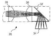
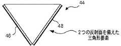
図4Aは、側視型光ファイバ走査システムの側方視界を提供する2つの反射面の構成の概略図で、例えば、身体管腔の対向面に向かって、180°離れた方向で2つの側方視界を達成するため、側視型光ファイバ走査システムのレンズ系に隣接して位置付けることができる、2つのミラー46及び48の三角形要素44の側面図を示している。 FIG. 4A is a schematic illustration of a configuration of two reflective surfaces that provide a side view of a side-view fiber optic scanning system, for example, two sides in a
側視型光ファイバ走査システム全体は、このミラー配置を含む内視鏡(この図には図示されない)を挿入する間及び/又は撤回する間回転させることができるので、内視鏡を挿入又は撤回しながら管腔壁全体を画像化することができ、あるいは、アセンブリ全体を回転させて、身体管腔内の静止位置において身体管腔のほぼ全360°を画像化することができる。管腔内で視界を回転させるには、単に近位端において軸体全体を回転させればよい。任意に、ミラー46及び48は、動力機械(図示なし)に結合された小さな軸体によってともに回転させることができるので、ミラーは、それらが互いにそこに沿って接触する線の中心を通って延びる共通の長手方向軸の周りを回転する。そのように回転されるので、ミラー46及び48は周辺の側方視界の全360°を画像化することができるようになる。図2A及び2Bに示されるような、単一のミラーを含む側視型光ファイバ走査システムの代表的な一実施形態に関連して、同じ方策を使用して、管腔の内表面周囲のより大きな角度範囲又は全360°を見ることができる。 The entire side view fiber optic scanning system can be rotated while inserting and / or retracting an endoscope (not shown in this figure) that includes this mirror arrangement, so that the endoscope can be inserted or retracted. While the entire lumen wall can be imaged, or the entire assembly can be rotated to image almost the entire 360 ° of the body lumen in a rest position within the body lumen. To rotate the field of view within the lumen, simply rotate the entire shaft at the proximal end. Optionally, the
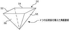
図4Bは、側視型光ファイバ走査システムの側方視界を提供する4つの反射面の角錐構成の概略図で、90°離れて向けられた方向で4つの側方視界を達成するため、側視型光ファイバ走査システムの側視型スコープ内のレンズ系に隣接して配置することができる、4つのミラー52、54、56、及び58の代表的な角錐形要素50を示している。これらのミラーもまた、周辺側方視界の周囲で全360°を見ることができるようにするため、動力機械(図示なし)によって、それらの共通の中心頂点を通って延びる中央軸体上で回転させることができる。 FIG. 4B is a schematic diagram of a pyramidal configuration of four reflective surfaces that provides a side view of a side-view fiber optic scanning system, and to achieve the four side views in directions oriented 90 ° apart, Shown is a representative pyramidal element 50 of four
図5は、著しい画像歪みを有するが、身体管腔内での側視型スコープの軸方向位置における色及び蛍光などの一般的な組織状態を正確に識別することができる側視型光ファイバ走査システムの軸対称反射面の概略図で、軸対称の円錐反射面62を使用して、側視型光ファイバ走査システムの光軸に垂直に見るための代表的な円錐形要素60を示している。 FIG. 5 shows a side-viewing fiber optic scan that has significant image distortion but can accurately identify common tissue conditions such as color and fluorescence at the axial position of the side-viewing scope within the body lumen. A schematic view of the system's axisymmetric reflective surface shows an exemplary
この円錐反射面は、側視型スコープの周りの周辺を連続して360°見ることができるが、円錐反射面62は平面ではないので、それが生成する画像は著しく歪むことになり、より具体的には大きな非点収差が生じる。円錐反射面の利点は、走査システムが、色及び蛍光など、身体管腔内の一般的な組織状態を正確に識別できるようになることであり、そのことは、所見領域の形状の詳細が特に重要ではない場合に十分であり得る。 This conical reflecting surface can continuously see 360 ° around the side-viewing scope, but since the
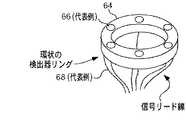
図6Aは、6つの光検出器及びそれら検出器から出る6つのリード線を含む側視型光ファイバ走査システム内の環状検出器リングの概略図で、フォトダイオードなどの6つの光検出器66が取り付けられた代表的な環状リング64を示している。 FIG. 6A is a schematic diagram of an annular detector ring in a side-view fiber optic scanning system that includes six photodetectors and six leads exiting them, with six
光検出器66は、環状リングの前面に埋め込むか、又は別の方法でそれに固着させることができる。環状リング64は、側視型スコープの側方(ならびに、後述するように、いくつかの代表的な実施形態では側視型スコープの前方)にある患者の内部組織から受け取った光を検出して、組織を画像化できるようにするため、側視型光ファイバ走査システムに使用することができる。信号リード線68は、光検出器が内部部位から受け取った入射光に応答して各検出器によって生成された信号を伝送するように光検出器66に結合されるので、信号は走査システムの近位端に搬送される。 The
図6Bは、側視型光ファイバ走査システム内で光を導く6つのマルチモードファイバを含む環状検出器リングの概略図で、6つのマルチモード集光用光ファイバ70の遠位端が(図6Aに示される光検出器の代わりに)環状リングに埋め込まれた、環状リング64を示している。 FIG. 6B is a schematic diagram of an annular detector ring that includes six multimode fibers that direct light within a side-view optical fiber scanning system, with the distal ends of the six multimode collection optical fibers 70 (FIG. 6A). An
したがって、これらの集光用光ファイバの遠位端は環状リング64の上面上に露出して、より詳細に後述するように、側視型光ファイバ走査システムを用いて画像化されている患者の内部組織からの光を受け取る。集光用光ファイバ72は、受け取った光を側視型光ファイバ走査システムのより近位側に配置された検出器に戻すため、環状リングの下方で近位側に延びる。例えば、光検出器(図示なし)は、側視型光ファイバ走査システムの近位端に隣接して、患者の身体外に配置することができ、あるいは、中間位置に配置することができる。 Thus, the distal ends of these concentrating optical fibers are exposed on the top surface of the
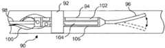
図7Aは、側視型光ファイバ走査システム内の走査機構及び走査されるシングルモードファイバの概略図で、側視型光ファイバ走査システムの代表的な走査機構90を示している。 FIG. 7A is a schematic diagram of a scanning mechanism in a side-viewing optical fiber scanning system and a single mode fiber to be scanned, showing a
走査機構90は、光ファイバの遠位端96を駆動して所望の走査パターンで動かす役割を果たす、圧電材料のチューブ94によって支持されるシングルモード光ファイバ98を備える。遠位端96は、一般に側視型スコープの中心の中でその遠位端に隣接して、圧電材料のチューブを越えて遠位側に延び、そこから一端が飛び出している。この圧電材料のチューブは、基部92によって走査装置内に保持される。 The
四分割電極(quadrant electrodes)102、104、及び106(ならびにこの図では見えていない他の1つ)は、圧電材料のチューブ上にめっきされ、光ファイバ98の遠位端96において2つの運動軸を作り出すため、印加電圧を用いて選択的に通電することができる。リード線100は、四分割電極それぞれに電圧信号を伝達して、各運動軸に対して圧電材料に通電する。この代表的な実施形態では、2つの軸は互いにほぼ直交する。チューブ圧電材料の一方の軸に加えられる増幅された正弦波と、他方の軸に加えられる余弦波とによって円形走査が作り出されるが、当業者であれば、光ファイバ98の遠位端96を適切に動かすことによって、様々な異なる走査パターンを生成できる。
四分割電極に加えられる電圧信号の振幅を適切に変調することによって、光ファイバの遠位端96から放射される光を用いて画像化のための所望の領域塗りつぶし二次元パターンを作り出すことができる。達成することができる様々な走査パターンのいくつかの例としては、線形走査、ラスタ走査、正弦走査、環状走査、らせん走査、及びプロペラ走査が挙げられる。いくつかの代表的な実施形態では、遠位端は、光ファイバ98の片持ちの遠位端の共振(又は近共振)周波数付近で動くように駆動され、それによって、加えられる所与の駆動信号に対してより大きな振幅を達成することができる。 By appropriately modulating the amplitude of the voltage signal applied to the quadrant electrode, the light emitted from the
図7Aは、光ファイバの片持ちの遠位端の横方向振動共振(lateral vibratory resonance)の第1モードを示しているが、図7Bに示される光ファイバスキャナ188は、片持ちの光ファイバ190が振動共振の第2モードで動くように駆動される。図7Bでは、第2のノードは、マイクロレンズ196に融着される片持ちの光ファイバ190の遠位端付近に配置される。 7A shows a first mode of lateral vibration resonance at the cantilevered distal end of the optical fiber, the
図7Bは、第2のモードの共振で振動する、遠位先端にマイクロレンズを備えたシングルモードファイバの概略図で、この実施形態では、片持ちの光ファイバ190を励起して、所望のパターン、所望の振幅、及び所望の周波数で動かすため、やはりチューブ94の圧電材料(又は別の適切なアクチュエータ)が用いられる。破線は、片持ちの光ファイバが180°位相ずれしているときの、その対応する形状及び配置を示している。 FIG. 7B is a schematic view of a single mode fiber with a microlens at the distal tip that vibrates at a second mode of resonance, in this embodiment exciting a cantilevered
光は、片持ちの光ファイバ190のコア192を通して、マイクロレンズ196が付着されたその遠位端に向かって導かれる。マイクロレンズ196は、ドラム型(筒型)レンズ、屈折率分布型(GRIN)レンズ、又は回折光学部品を含むことができる。この代表的な実施形態では、そのように励起されたとき、片持ちの光ファイバは、有効光源198に実質的に近接した振動ノード(vibratory node)194を有する。有効光源198から振動ノード194が変位するため、主にマイクロレンズ196の回転によって、ただしマイクロレンズならびに片持ちの光ファイバ190の遠位端が並進することによっても走査が生じる。 Light is directed through the
マイクロレンズ196から放射された光202はわずかに収束し、走査レンズ200によって焦点が合わされて、焦点206へと収束する集光204が生成される。したがって、片持ちの光ファイバ190の移動により、有効光源198が並進距離208を進み、上側回転距離210a及び下側回転距離210b(どちらも縮尺によらない)をほぼ通って集光が回転する。したがって、光ファイバスキャナ188の焦点206の走査は、主にマイクロレンズの回転によって、ただし、より少ない程度では有効光源の並進によっても得られる。本明細書にて説明するように、マイクロレンズによって放射された光は、側視型光ファイバスコープの1つ又は複数の側方に方向付けられて、ROIを、例えば、身体管腔の内表面組織を、ならびにいくつかの実施形態では側視型スコープの前方を照明する。 The light 202 emitted from the
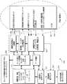
図8は、本発明による、画像化、監視、及び診断付与のために光ファイバとともに使用可能な、走査システム内の信号の機能的フローを説明する代表的なブロック図で、患者の身体内部にある側視型スコープの様々な構成要素によって生成される信号が、外部計測器によってどのように処理されるか、また、走査システムを制御して連続する走査フレームにおける走査パラメータ(1つ又は複数)を変化させるのに使用される信号が、患者の身体内部に位置付けられた、側視型光ファイバ走査システム上の構成要素にどのように入力されるかを示す、走査システム350を示している。 FIG. 8 is a representative block diagram illustrating the functional flow of signals within a scanning system that can be used with an optical fiber for imaging, monitoring, and diagnostic delivery according to the present invention, inside a patient's body. How the signals generated by the various components of a side-viewing scope are processed by an external instrument, and the scanning parameter (s) in successive scanning frames controlling the scanning system
集積された画像化及び他の機能性を提供するため、走査システム350は、したがって、患者の身体外部に留まる構成要素と、内部で使用されるもの(即ち、破線352内の構成要素)とに分割される。ブロック354は、側視型光ファイバ走査システムの遠位端に含まれ得る、配置された機能性構成要素を列挙している(これらの構成要素の全てが側視型光ファイバ走査システムに実際に必要とは限らないことに留意のこと)。 In order to provide integrated imaging and other functionality, the
図面に示されるように、これらの代表的な構成要素としては、照明光学系及びスキャナ、1つ又は複数の電気機械的走査アクチュエータ、1つ又は複数の制御用スキャナセンサ、所望の部位を画像化する光子コレクタ及び/又は検出器、ならびに任意に、診断用ならびに治療及び監視用の追加の光子コレクタ及び/又は検出器を挙げることができ、それらの1つ又は複数は、異なる走査フレームの間に用いられる照明及び/又は走査パラメータを変化させることによって、同じ走査装置を使用して実現することができる。走査システム350に関して、特定の実施形態では、特定の用途に実際に必要な機能性構成要素のみが含まれてもよいことにも留意されたい。また、画像化以外の追加の機能は、診断、もしくは治療、又はそれらの機能の組み合わせであり得る。 As shown in the drawings, these representative components include illumination optics and a scanner, one or more electromechanical scanning actuators, one or more control scanner sensors, and an image of the desired site. Photon collectors and / or detectors, and optionally, additional photon collectors and / or detectors for diagnostic and therapeutic and monitoring purposes, one or more of which may be used during different scan frames. It can be realized using the same scanning device by changing the illumination and / or scanning parameters used. It should also be noted that with respect to
外部的に、照明光学系及びスキャナ(1つ又は複数)は、ブロック356に示されるように、画像化光源及び変調器から光を供給される。光ファイバ系の遠位端に導かれるRGB光、UV光、IR光、偏光、及び/又は高強度光を生成するための外部光源系のいくつかの代表的な実施形態に関する更なる詳細は、当業者には明白になるであろう。走査を制御するスキャナセンサを使用することができ、またそれらは、スキャナアクチュエータ、照明源、及び変調器にフィードバックされる信号を生成して、ブロック360の信号処理後の走査制御を実現することができる。初期化に基づいて、共振及びオープンフィードバックシステムには温度が影響するため、センサは単に1つ又は複数の温度センサであってもよい。また、走査システムを通して伝達される大電力の治療用照明により、又は組織から放射されて戻る熱の間接的な結果として、温度上昇が生じることがある。多くの用途では、スキャナセンサは不要であり、省略することができる。 Externally, the illumination optics and scanner (s) are supplied with light from the imaging light source and modulator, as shown in
ブロック360では、画像化用光子コレクタ及び/又は検出器によって、また診断/治療及び監視の目的で用いられる他の光子コレクタ及び/又は検出器によって生成される電子信号を使用して、画像信号フィルタリング、バッファリング、走査変換、増幅、ならびに他の処理機能を実現することができる。ブロック356及び360は、各ブロックそれぞれによって行われる機能を容易にする信号を搬送するため、二方向的に相互接続される。同様に、これらのブロックはそれぞれブロック362と連通して二方向的に結合され、ブロック362では、コンピュータワークステーションのユーザインターフェースと、又は画像取得と処理に、関連プログラムの実行に、もしくは他の有用な機能の実施に用いられる他の演算装置と結合された、信号を処理するアナログ/デジタル(A/D)及びデジタル/アナログ(D/A)変換器が提供される。 In
コンピュータワークステーションからの制御信号は、ブロック362にフィードバックされ、適切であれば、ブロック356、358、及び360に提供された機能それぞれを制御又は作動するアナログ信号に変換される。ブロック362内のA/D変換器及びD/A変換器はまた、データ格納が提供されるブロック364に、かつブロック366に二方向的に結合される。ブロック366は、患者の身体内の側視型光ファイバ内視鏡の端部を操作し、位置付け、かつ安定化するのを助けるユーザインターフェースを表す。 Control signals from the computer workstation are fed back to block 362 and, if appropriate, converted to analog signals that control or operate each of the functions provided in
ブロック364では、データ格納は、患者の身体内の検出器によって生成された画像データを格納し、走査光ファイバによって実現された画像化及び機能に関連する他のデータを格納するのに使用される。ブロック364も、コンピュータワークステーション368に、かつブロック370の対話型表示モニタ(1つ又は複数)に二方向的に結合される。ブロック370は、ブロック360からの入力を受け取って、ROIの画像を対話式で表示できるようにする。それに加えて、ブロック372に示されるように、1つ又は複数の受動映像表示モニタがシステム内に含まれてもよい。他のタイプの表示装置、例えば、ヘッドマウントディスプレイ(HMD)システムを提供して、医療従事者が擬似ステレオ画像としてROIを見られるようにすることもできる。 In
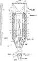
図9は、内部部位からの光を集光するために単一のミラー及び集光用光ファイバを使用することを説明する、患者の体内で使用される側視型光ファイバ走査システムの部分の概略図で、患者の体内で使用することができ、走査システムの遠位端の一方の側にある内部組織を画像化するために反射面32を含む、代表的な側視型光ファイバ走査システム120の遠位部分の概略図である(図面は縮尺どおりに描かれておらず、全寸法について、特に図示される側視型スコープの直径に関して大幅に小さいことに留意のこと)。 FIG. 9 illustrates a portion of a side-view fiber optic scanning system used in a patient's body, illustrating the use of a single mirror and collection fiber to collect light from an internal site. 1 is a schematic side view optical fiber scanning system that can be used in a patient's body and includes a
反射面32は、裏面が反射性材料でコーティングされており、光が、裏面上の反射性コーティングから反射する前にガラスの厚さを通って移動せざるを得ない場合に起こる望ましくない反射を排除するため、この代表的な実施形態では前面反射ミラーを備える。この代表的な実施形態では、エンドキャップ142が反射面32及びレンズ130を支持する。 The
走査システムの近位端からの光は、照明用シングルモード光ファイバ98によって方向付けられ、患者の身体内の所望の内部部位まで前進させることができる走査システムの遠位端まで光ファイバ内を移動する。シングルモード光ファイバの遠位端96は、上述したように(図7Aに関連して)、四分割電極に加えられる電気信号によって駆動される圧電材料のチューブ94によって、所望の走査パターン、例えばらせんパターンで振動される。光ファイバの動いている遠位端を出る光は、レンズ系を通って移動し、反射面によって外向きに反射される。走査システムの遠位端の側面から出る光136は、例えば身体管腔の側面にあってもよい患者の内部組織132に衝突する。 Light from the proximal end of the scanning system is directed by the illuminating single mode
組織によって反射された光の一部は、遠位端が一般にレンズ130の周りの離間した位置に配置される、6つの集光用光ファイバ70によって集光される。図9の側視型スコープでは、集光用光ファイバのうち2つのみが走査システムの遠位端に示されるが、近位端では6つ全てが概略的に示されている。 A portion of the light reflected by the tissue is collected by six collecting
集光用光ファイバのいずれかについてレンズ130付近で方向の急激な変化が必要な場合、ミラー71(又は、光の内部全反射(TIR)を呈するプリズムなどの他の光学部品)を使用して、戻ってくる光を集光用光ファイバの1つの隣接した遠位端内へと偏向することができる。 Use a mirror 71 (or other optical component such as a prism that exhibits total internal reflection (TIR) of light) if a sudden change in direction near the
内部組織から受け取られた光は、集光用光ファイバに沿って走査システムの遠位端から近位端へと導かれる。外装122は、側視型光ファイバ走査システムの遠位端においてアセンブリ全体を支持し、走査システムを患者の管腔又は他の内部部位に挿入するのを容易にする。光ファイバ走査システム120を使用して、その周囲にある患者の内部組織からの散乱光、偏光、又は蛍光を集光することができる。患者の内部組織の画像を作り出すため、散乱光が集光されてもよい。赤色、緑色、及び青色(RGB)レーザからの光を混合して白色光を生成し、それを、走査システムの近位端において照明用シングルモード光ファイバ内へと方向付けることができる。この光は、本明細書に記載されるような走査システムを通して導かれ、光の一部は、患者の内部組織によって散乱され、やはり上述したように、走査システムを通して戻される。 Light received from the internal tissue is directed along the collection optical fiber from the distal end to the proximal end of the scanning system. The
光は、集光用光ファイバを通して走査システムの遠位端から走査システムの近位端へと移動し、次にそこでRGB光に分離される。次に、光の各色の強度が光検出器(この図には図示なし)によって測定され、患者の内部組織の画像をフルカラーで作り出すのに使用される。あるいは、単色光を使用して単色画像を生成することができ、又は、組織から散乱した白色光を、RGB色成分に分割することなく検出して、内部組織のグレースケール画像を生成することができる。 The light travels through the collecting optical fiber from the distal end of the scanning system to the proximal end of the scanning system, where it is then separated into RGB light. The intensity of each color of light is then measured by a photodetector (not shown in this figure) and used to create a full color image of the patient's internal tissue. Alternatively, monochromatic light can be used to generate a monochromatic image, or white light scattered from the tissue can be detected without being divided into RGB color components to produce a grayscale image of the internal tissue. it can.
蛍光画像化の場合、走査システムの近位端において照明用シングルモード光ファイバ98内へと方向付けられる光源からの光、即ち励起光は、単色であり、がん組織など、特定のタイプの組織が蛍光を放射するように選択された波長のものである。任意の見込まれるがん組織又は他の目的組織からの蛍光は、蛍光を励起するために走査システムに入力される単色の照明光よりも長い波長のものである。近位端において走査システム内へと方向付けられるこの単色光は、走査システムを通って移動し、光136として走査システムの遠位端を出る。 In the case of fluorescence imaging, the light from the light source that is directed into the illuminating single mode
患者の内部組織からの蛍光の一部は、集光用光ファイバ70内へと後方散乱し、それらのファイバを通して走査システムの近位端に導かれる。蛍光のみが光検出器によって検出されることを確保するため、励起光全てを減衰する放射フィルタを、任意に、走査システムの近位端における光検出器の前に配置することができる。 Some of the fluorescence from the patient's internal tissue is backscattered into the collection
更なる代替例として、この走査システムによって、組織の表在層を画像化する偏光を集光することができる。光源からの光(レーザなどであるが、この図には図示されない)は偏光フィルタを通過し、結果として得られる偏光は、照明用光ファイバ98の近位端内へと方向付けられる。この代表的な実施形態では、照明用光ファイバは偏波面保持シングルモード光ファイバである。偏光は、照明用光ファイバを通って移動し、所望の走査パターンで走査するように駆動される遠位端96を出る。走査光は、走査システムの遠位端の側面で(即ち、側視型スコープの側面で)内部組織132に向かって反射される。内部組織によって反射又は散乱した光の一部は集光用光ファイバ70に入る。 As a further alternative, the scanning system can collect polarized light that images the superficial layer of tissue. Light from the light source (such as a laser, but not shown in this figure) passes through a polarizing filter and the resulting polarized light is directed into the proximal end of the illumination
ワイヤグリッド偏光子180(その詳細は図13に示され、後述される)などの偏光子は、走査システムの遠位端において、集光用光ファイバ70の遠位端の上に位置付けられてもよい。偏光子は、内部組織から受け取られた光の平行及び垂直偏光成分を、集光用光ファイバ70の異なる群に分離するので、特定の光ファイバを通して導かれた偏光の向きの強度は、走査システムの近位端に配置された光検出器(図示なし)によって検出することができる。 A polarizer such as a wire grid polarizer 180 (details of which are shown in FIG. 13 and described below) may be positioned over the distal end of the collection
図10は、側方視及び前方視の両方を提供するためにビームスプリッタを含み、側視型スコープの側方及び遠位側の両方にある内部組織からの光を検出する光検出器の環状リングを含む、側視型スコープの代表的な一実施形態を示す図で、患者の体内で使用することができ、レンズ124、126、130、及び138、ならびに45°ビームスプリッタ32を含む、側視型光ファイバ走査システム140の一部の概略図である。 FIG. 10 illustrates an annular detector that includes a beam splitter to provide both lateral and forward viewing and detects light from internal tissue on both the lateral and distal sides of the lateral scope. FIG. 6 shows an exemplary embodiment of a side-viewing scope including a ring, which can be used in a patient's body and includes
ビームスプリッタ32は、部分反射ミラー、ダイクロイックビームスプリッタ、又は偏光ビームスプリッタであることができる。側視型光ファイバ走査システム140のこの代表的実施形態は、図1に概略的に示したのと類似のやり方で、患者の身体内部にあるROIの前方視界及び側方視界の両方を提供する。レンズ130及び138は、マルチモード集光用ファイバ70の代わりに光検出器66を含む、環状検出器リング64に取り囲まれている。 The
上述したように、離間した光検出器66(例えば、フォトダイオード)は、側視型スコープの側方に対して、ならびに前方から、内部組織132からの光134を受け取る。光検出器によって生成された信号は、検出器信号リード線68を通して走査システムの近位端に導かれ、そこで内部部位の画像を生成するのに使用することができる。この走査システムを使用して、図9の走査システム120と関連して上述したのと同じように、周囲にある患者の内部組織からの散乱光、偏光、又は蛍光を集光することができる。他の参照番号は全て、図9の代表的な実施形態及び図7Aの代表的走査機構90と関連して上述した構成要素に関する。 As described above, the spaced photodetectors 66 (eg, photodiodes) receive light 134 from the
図11は、内部部位における組織を走査するために軸対称の反射円錐面を使用することを説明する側視型光ファイバ走査システムに使用されるスコープの他の代表的な実施形態の概略図で、やはり患者の体内に位置付けることができる、側視型光ファイバ走査システム150の別の代表的な実施形態の遠位部分の概略図である。 FIG. 11 is a schematic diagram of another exemplary embodiment of a scope used in a side-view fiber optic scanning system illustrating the use of an axisymmetric reflective conical surface to scan tissue at an internal site. FIG. 4 is a schematic view of a distal portion of another exemplary embodiment of a side-view fiber
走査システム150は、軸対称の反射円錐面62(図5に示されるような)を含む。円錐反射面は、360°の視界を提供するが、著しい画像の歪み及び非点収差も生じる。したがって、組織の正確な画像は、この円錐反射面を使用して容易には作り出されない。しかし、側視型光ファイバ走査システム150は、身体管腔又は患者の身体内の他の所望の部位内で、側視型スコープの軸方向位置における色及び蛍光などの一般的な組織状態を正確に識別することができる。走査システム150に使用される他の構成要素は、全体として、図9の側視型光ファイバ走査システム120について示されるものと同じであり、上述した構成要素及びそれらの機能性の説明は、光ファイバ走査システム150に等しく適用可能である。 The
図12Aは、2つ以上の反射面を有するミラーアセンブリを使用する側視型スコープの更に他の代表的な実施形態の概略図で、患者の体内で使用することができる、代表的な光ファイバ走査システム160の遠位部分の概略図である(図面は縮尺どおりに描かれておらず、全寸法について、特に図示される側視型スコープの直径に関して大幅に小さいことに留意のこと)。 FIG. 12A is a schematic diagram of yet another exemplary embodiment of a side-viewing scope that uses a mirror assembly having two or more reflective surfaces, and is a representative optical fiber that can be used in a patient's body. FIG. 4 is a schematic view of the distal portion of the scanning system 160 (note that the drawings are not drawn to scale and are significantly smaller in all dimensions, particularly with respect to the diameter of the side-viewing scope shown).
この実施形態は、代表的な走査機構90を含むが、図7Bに示されるような走査機構188とほぼ類似のやり方で動作して、第2のモードの共振を生成する。光ファイバ走査システム160には、全て外装122内で支持される、レンズ126、128、及び130、ならびに反射面46及び48(図4Aに示し、上述したもの)が含まれる。走査システムの近位端からの光は、照明用シングルモード光ファイバ98によって方向付けられ、患者の身体内の所望の内部部位まで前進させることができる走査システムの遠位端へと光ファイバ内を移動する。 This embodiment includes an
シングルモード光ファイバの遠位端96(ただし、ここではマイクロレンズ95に融着される)は、振動するように駆動されて、上述したように(図7A及び7Bに関連して)、四分割電極に加えられる電気信号によって通電される圧電材料のチューブ94によって所望の走査パターン、例えば、らせんパターンが達成される。シングルモードカンチレバー96の先端にはマイクロレンズ95が融着され、それが、マイクロレンズ196(図7Bに示される)に関連して上述したように、レンズ126に衝突する照明の半平行光線を生成する。マイクロレンズ95を通して光ファイバの動いている遠位端を出る光は、レンズ126を通って移動し、反射面48及び46それぞれによってレンズ128及び130を通して外向きに反射される。 The
これら反射面の支持構造は、この代表的な実施形態に示されるように、図4Aにも示されるような2つの反射面46及び48のみを有する三角形要素であってもよく、あるいは、図4Bに関連して上述したような、4つの反射面52、54、56、及び58を備えた角錐面50を含んでもよい。支持構造140は、反射面ならびにレンズ128及び130を外装122の遠位端上の適所で保持する。更なる代替例として、図11に示される側視型光ファイバ走査システム150の代表的な実施形態に関連して考察したように、平面の反射面の代わりに図5に示される円錐面が使用されてもよい。 These reflective surface support structures may be triangular elements having only two
図12Aの走査システムの遠位端の側面から出る光136は、例えば身体管腔の側面にあってもよい患者の内部組織132に衝突する。次に、光の一部は、散乱光134としてこの内部組織から走査システム内へと後方散乱されて、レンズ130を通って戻り、反射面から反射されてもよい。組織によって後方散乱又は反射された光の一部は、遠位端がレンズ126の周りの離間した位置に配置された6つの集光用光ファイバ70によって集光される。内部組織から受け取られた光は、集光用ファイバに沿って走査システムの遠位端から近位端へと導かれる。外装122は、側視型光ファイバ走査システムの遠位端でアセンブリ全体を支持し、走査システムを患者の管腔又は他の内部部位に挿入するのを容易にする。
図12Bは、図12Aに類似しているが、内部部位の組織からの光を検出するため、マルチモード集光用ファイバの代わりに環状検出器リングを使用する、代替の代表的な実施形態の概略図で、患者の身体内で使用することができる代表的な側視型光ファイバ走査システム170の遠位部分の概略図である。 FIG. 12B is similar to FIG. 12A, but of an alternative exemplary embodiment that uses an annular detector ring instead of a multimode collection fiber to detect light from tissue at the internal site. FIG. 4 is a schematic diagram of a distal portion of a representative side-view fiber
この走査システムは、システムの遠位端が、マルチモード集光用ファイバ70の代わりに光検出器66(図6Aにも示される)を備えた環状検出器リング64を使用して、内部組織132からの光134を受け取ること以外は、図12Aの側視型光ファイバ走査システム160に類似している。図12Aについて上述したように、光は走査システムを通して近位端から遠位端へと方向付けられ、やはり上述したように、光の一部は、患者の内部組織から散乱して、走査システムの遠位端内へと戻る。したがって、図12Bの光ファイバ走査システム170の構成要素の多くは、図12Aの光ファイバ走査システム160のものと同一である。 This scanning system uses an
しかし、光が反射面46又は48から反射された後、集光用光ファイバ70を通して光が組織から移動する代わりに、光は、図6A及び10に関連して上述したように、環状検出器リング64の遠位面の周りで離間した光検出器66上に衝突する。光検出器に結合された検出器リード線68は、走査システムの遠位端にある環状検出器リング内の光検出器によって生成された信号を、走査システムの近位端に伝達し、そこで、患者の内部組織の画像を構築するのに情報が使用される。 However, instead of the light moving from the tissue through the collecting
図9の代表的な実施形態について記載したように、側視型光ファイバ走査システムを使用して、周囲にある患者の内部組織からの散乱光、偏光、又は蛍光を集光することができる。蛍光を検出する場合、励起光の波長を減衰し、光検出器がフィルタを容易に透過する蛍光のみを検出できるようにするため、適切な放射フィルタ(図示なし)が、走査システムの遠位端で光検出器の上に置かれる。同様の形式で、偏光のみを検出するため、偏光子が、側視型光ファイバ走査システムの遠位端で光検出器の上に位置付けられる。 As described for the exemplary embodiment of FIG. 9, a side-view fiber optic scanning system can be used to collect scattered light, polarized light, or fluorescence from surrounding patient internal tissue. When detecting fluorescence, an appropriate emission filter (not shown) is used at the distal end of the scanning system to attenuate the wavelength of the excitation light and allow the photodetector to detect only fluorescence that is easily transmitted through the filter. Placed on top of the photodetector. In a similar manner, a polarizer is positioned over the photodetector at the distal end of the side-view fiber optic scanning system to detect only polarized light.
図13は、図12Aに示されるスコープなどにおいて、走査用光ファイバの周りの環状リング内に配置された集光用光ファイバの遠位端の上に置かれたとき、側視型光ファイバ走査システムにおいて偏光を検出するのに使用することができる、代表的なワイヤグリッド偏光子の概略図で、図13に示されるワイヤグリッド偏光子180などの偏光子を使用して、偏光を検出し、直線偏光の異なる向きを分離することができる。 FIG. 13 is a side view optical fiber scanning when placed on the distal end of a collection optical fiber disposed in an annular ring around the scanning optical fiber, such as in the scope shown in FIG. 12A. A schematic diagram of a typical wire grid polarizer that can be used to detect polarization in the system, using a polarizer such as the
偏光子180のこの代表的実施形態は、環状偏光子の一方の半分が、他方の半分に配置されたワイヤのグリッド(grid with wires)176に垂直に向けられたワイヤのグリッド174を含む、円環172の形態である。この環状偏光子が、側視型光ファイバ走査システムの遠位端において集光用光ファイバ70の遠位端の上(又は光検出器66の上)に位置付けられる場合、集光用光ファイバ(又は光検出器)の半分は直線偏光の1つの向きを集光し、集光用光ファイバの他方の半分は、それに垂直な向きを有する直線偏光の光を集光する。同じ機能に役立つ他のタイプの偏光子が使用されてもよく、例えば、偏光の向きを集光用光ファイバ(又は光検出器)の一方の半分と他方の半分とで異なる向きにして、別個の光学偏光子を、各集光用光ファイバ(又は光検出器)の遠位端の上に嵌合することができる。 This exemplary embodiment of the
本明細書に開示した概念を、それらを実施するのに好ましい形態及びその修正例に関して記載してきたが、当業者であれば、以下の請求項の範囲内でそれらに対する他の多くの修正を行うことができることを理解するであろう。したがって、これらの概念の範囲は、いかなる形でも上述の説明によって限定されるものではなく、その代わりに、以下の請求項を参照して全体が決定されるものとする。 Although the concepts disclosed herein have been described in terms of preferred forms for implementing them and modifications thereof, those skilled in the art will make many other modifications thereto within the scope of the following claims. You will understand that you can. Accordingly, the scope of these concepts is not to be limited in any way by the above description, but instead should be determined entirely with reference to the following claims.
Claims (29)
Translated fromJapanese(a)近位端と遠位端との間を延び、前記近位端は、外部光源に結合して、前記外部光源によって生成された光を受け取り、前記遠位端に隣接した領域を照明するのに使用するために光を前記遠位端に向かって導くように構成された光ファイバと、
(b)前記光ファイバの前記遠位端に配置され、前記光ファイバに結合され、前記光ファイバを通して導かれた光が、前記遠位端から第1の方向で放射される自由端を有し、照明に使用される光のみを導く走査装置と、
(c)前記走査装置の前記自由端を所望のパターンで動かすための駆動力を提供するアクチュエータと、
(d)前記走査装置の前記自由端に隣接して配置され、前記自由端から放射された前記光の少なくとも一部分を前記第1の方向にほぼ直交する第2の方向で反射し、反射面から反射した前記光の少なくとも前記一部分を側方に向かって方向付ける反射面と、
(e)前記反射面から反射した前記光によって照明され、前記側方にある領域からの光を検出し、前記領域の画像を生成するのに使用可能な信号を生成する少なくとも1つの光検出器と
を備えることを特徴とする側視型スコープ。In a side-viewing scope that images the area inside the patient's body,
(A) extending between a proximal end and a distal end, wherein the proximal end is coupled to an external light source to receive light generated by the external light source and illuminate a region adjacent to the distal end An optical fiber configured to direct light toward the distal end for use in
(B) having a free end disposed at the distal end of the optical fiber, coupled to the optical fiber, and guided through the optical fiber to be emitted from the distal end in a first direction; A scanning device that directs only the light used for illumination;
(C) an actuator that provides a driving force for moving the free end of the scanning device in a desired pattern;
(D) is disposed adjacent to the free end of the scanning device and reflects at least a portion of the light emitted from the free end in a second direction substantially perpendicular to the first direction, from a reflective surface; A reflective surface for directing at least the portion of the reflected light laterally;
(E) at least one photodetector that is illuminated by the light reflected from the reflecting surface, detects light from the lateral region, and generates a signal that can be used to generate an image of the region; A side-viewing scope characterized by comprising:
(a)前記走査装置によって放射された前記光を前記第2の方向で反射するミラーと、
(b)反射性であって、前記走査装置によって放射された前記光を反対方向で反射する2つの対向面を有し、前記反対方向のどちらかが前記第2の方向を含み、前記反対方向の他方が第3の方向を含む三角形要素と、
(c)反射面を有する円錐形要素と、
(d)反射性であって、前記走査装置によって放射された光を前記側方に向かって異なる方向でそれぞれ反射する2つを超える面を有する角錐形要素と、
(e)前記走査装置によって放射された前記光の一部分を前記側方に向かって反射し、前記光の残りの部分を透過する部分反射ビームスプリッタと、
(f)前記走査装置によって放射された前記光の一部の波長を反射し、他の波長を透過するダイクロイックビームスプリッタと、
(g)第1の方向で偏光された直線偏光を反射し、前記第1の方向に直交する第2の方向で偏光された直線偏光を透過する偏光ビームスプリッタと
から成る群から選択されることを特徴とする請求項1に記載の側視型スコープ。The reflective surface is
(A) a mirror that reflects the light emitted by the scanning device in the second direction;
(B) two reflective surfaces that are reflective and reflect the light emitted by the scanning device in opposite directions, one of the opposite directions including the second direction, the opposite direction A triangular element, the other of which includes a third direction;
(C) a conical element having a reflective surface;
(D) a pyramidal element having more than two surfaces that are reflective and each reflect light emitted by the scanning device in different directions towards the sides;
(E) a partially reflecting beam splitter that reflects a portion of the light emitted by the scanning device toward the side and transmits the remaining portion of the light;
(F) a dichroic beam splitter that reflects some wavelengths of the light emitted by the scanning device and transmits other wavelengths;
(G) a polarization beam splitter that reflects linearly polarized light polarized in a first direction and transmits linearly polarized light polarized in a second direction orthogonal to the first direction; The side-viewing scope according to claim 1, wherein:
(a)平行偏光と、
(b)垂直偏光と、
(c)組織から散乱された散乱光と
(d)組織によって放射された蛍光と、
(e)ろ過された組織からの光
とから成る群から選択されることを特徴とする請求項4に記載の側視型スコープ。The proximal end of each collection optical fiber is configured to couple to a corresponding photodetector that detects at least one specific type of light, and the specific type of light detected is
(A) parallel polarized light;
(B) vertical polarization;
(C) scattered light scattered from the tissue; (d) fluorescence emitted by the tissue;
5. The side-viewing scope according to claim 4, wherein the side-viewing scope is selected from the group consisting of (e) light from filtered tissue.
(a)線形走査と、
(b)ラスタ走査と、
(c)正弦走査と、
(d)環状走査と、
(e)らせん走査と、
(f)プロペラ走査と
のいずれかを行うことを特徴とする請求項1に記載の側視型スコープ。The actuator moves the scanning device in the desired pattern;
(A) linear scanning;
(B) raster scanning;
(C) sinusoidal scanning;
(D) annular scanning;
(E) spiral scanning;
(F) Propeller scanning is performed, The side-view type scope according to claim 1 characterized by things.
(a)近位端及び遠位端を有し、前記近位端は、光源によって生成された光を、前記光ファイバを通して前記光ファイバの前記遠位端へと導くように、前記光源に結合するように構成される可撓性光ファイバと、
(b)前記光ファイバの前記遠位端に配置され、前記光ファイバを通して導かれた前記光を受け取り、前記光ファイバの共振周波数付近において所望の走査パターンで動きながら前記光を放射するように駆動される共振走査装置と、
(c)前記共振走査装置によって放射された前記光を受け取るため、前記共振走査装置の遠位側に配置され、受け取られた前記光の少なくとも一部分を側方に向かって反射して、前記側方にある領域を走査するように構成された反射器と、
(d)近位端及び遠位端を有し、前記遠位端は、前記領域からの光を受け取るように配置され、処理のため、前記光を前記近位端へと導く少なくとも1つの集光用光ファイバと
を備えることを特徴とする側視型スコープ。In a side-viewing scope used to scan areas inside the patient's body,
(A) having a proximal end and a distal end, wherein the proximal end is coupled to the light source to direct light generated by the light source through the optical fiber to the distal end of the optical fiber; A flexible optical fiber configured to:
(B) disposed at the distal end of the optical fiber, receiving the light guided through the optical fiber, and driving to emit the light while moving in a desired scanning pattern near a resonance frequency of the optical fiber A resonant scanning device,
(C) disposed on a distal side of the resonant scanning device for receiving the light emitted by the resonant scanning device, reflecting at least a portion of the received light laterally to the lateral A reflector configured to scan an area at
(D) having a proximal end and a distal end, the distal end being arranged to receive light from the region and at least one collection for directing the light to the proximal end for processing. A side-viewing scope comprising: an optical fiber.
(a)垂直偏光と、
(b)平行偏光と、
(c)前記領域内の組織から散乱された光によって生成された散乱光と、
(d)蛍光を発している前記領域内の組織によって生成された蛍光と、
(e)ろ過された組織からの光
とから成る群から選択される少なくとも1つのタイプの光の前記強度を示すことを特徴とする請求項17に記載の側視型スコープ。The signal generated by the detector that receives the light directed through the collecting optical fiber is:
(A) vertical polarization;
(B) parallel polarized light;
(C) scattered light generated by light scattered from tissue in the region;
(D) fluorescence generated by tissue in the region emitting fluorescence;
18. The side-viewing scope according to claim 17, characterized by indicating the intensity of at least one type of light selected from the group consisting of (e) light from filtered tissue.
(a)患者の身体内に前記側視型スコープを導入する段階と、
(b)外部光源からの光を、光ファイバを通して前記側視型スコープの遠位端に向かって導く段階と、
(c)前記光ファイバに結合された固定端を有する走査装置の、単に光を放射する自由端を、前記自由端が所望のパターンで動くようにして動かし、前記走査装置に結合された、前記領域からの光は導かない前記光ファイバのほぼ前方に方向付けられた光を放射する段階と、
(d)前記走査装置から放射された前記光の少なくとも一部分を前記所望のパターンで前記側視型スコープの側方に向かって反射させて、前記領域を照明する段階と、
(e)前記側視型スコープの前記側方にある前記領域から光を受け取って、前記側視型スコープの前記側方にある前記領域の画像を生成する段階と
を含むことを特徴とする側視型スコープの画像化方法。A method for imaging a side-viewing scope that images a region lateral to a distal end of a side-viewing scope configured to be introduced into a patient's body, comprising:
(A) introducing the side-viewing scope into the patient's body;
(B) directing light from an external light source through an optical fiber toward the distal end of the side-viewing scope;
(C) a scanning device having a fixed end coupled to the optical fiber, simply moving a free end that emits light, such that the free end moves in a desired pattern, and coupled to the scanning device, Emitting light directed substantially in front of the optical fiber that does not guide light from the region;
(D) illuminating the region by reflecting at least a portion of the light emitted from the scanning device toward the side of the side-viewing scope in the desired pattern;
(E) receiving light from the region on the side of the side-viewing scope and generating an image of the region on the side of the side-viewing scope. Visual scope imaging method.
(a)前記走査装置から放射された前記光の少なくとも前記一部分を、前記側視型スコープの対向面に向かって2つの反対方向で反射させる段階と、
(b)前記走査装置から放射された前記光の少なくとも前記一部分を、前記側視型スコープの前記側方の周りの異なる範囲に向かって複数の異なる方向で反射させる段階と、
(c)前記走査装置から放射された前記光の少なくとも前記一部分を、前記側視型スコープの前記側方の周りを延びる面内で反射させる段階と、
(d)前記走査装置から放射された前記光を、前記光の一部分が前記側視型スコープの前記側方に向かって反射され、前記光の残りの部分が前記側視型スコープの前方に伝達されるように分割する段階と
のいずれかを含むことを特徴とする請求項20に記載の側視型スコープの画像化方法。The step of reflecting light emitted from the scanning device comprises:
(A) reflecting at least a portion of the light emitted from the scanning device in two opposite directions toward an opposing surface of the side-viewing scope;
(B) reflecting at least a portion of the light emitted from the scanning device in a plurality of different directions toward different ranges around the sides of the side-viewing scope;
(C) reflecting at least a portion of the light emitted from the scanning device in a plane extending around the side of the side-viewing scope;
(D) A part of the light is reflected toward the side of the side-viewing scope and the remaining part of the light is transmitted to the front of the side-viewing scope. 21. The method for imaging a side-viewing scope according to claim 20, further comprising the step of dividing as described above.
(a)平行偏光と、
(b)垂直偏光と、
(c)組織から散乱された散乱光と、
(d)組織によって放射された蛍光と、
(e)ろ過された組織からの光と
から成る群から選択される特定のタイプのものであることを特徴とする請求項22に記載の側視型スコープの画像化方法。Detecting light from at least one of the group consisting of the region and the other region, wherein the detected light comprises:
(A) parallel polarized light;
(B) vertical polarization;
(C) scattered light scattered from the tissue;
(D) fluorescence emitted by the tissue;
23. The imaging method for a side-viewing scope according to claim 22, wherein the imaging method is of a specific type selected from the group consisting of: (e) light from filtered tissue.
(a)線形走査と、
(b)ラスタ走査と、
(c)正弦走査と、
(d)環状走査と、
(e)らせん走査と、
(f)プロペラ走査と
のいずれかを行う、前記自由端を前記所望のパターンで駆動する段階を含むことを特徴とする請求項20に記載の側視型スコープの画像化方法。Moving the free end of the scanning device comprises the steps of:
(A) linear scanning;
(B) raster scanning;
(C) sinusoidal scanning;
(D) annular scanning;
(E) spiral scanning;
21. The imaging method for a side-viewing scope according to claim 20, further comprising the step of: driving the free end with the desired pattern.
(a)前記側視型スコープが前記患者の身体内の所望部位に位置付けられている間、
(b)前記側視型スコープが前記患者の身体に導入されている間、又は、
(c)少なくとも前記側視型スコープが前記患者の身体から撤回されている間
に生じることを特徴とする請求項20に記載の側視型スコープの画像化方法。The step of rotating the side-viewing scope further includes rotating the side-viewing scope such that the side-viewing scope increases a viewing angle while imaging the inside of the patient's body. At least,
(A) While the side-viewing scope is positioned at a desired site in the patient's body,
(B) while the side-viewing scope is being introduced into the patient's body, or
21. The method for imaging a side-viewing scope according to claim 20, wherein the imaging is performed at least while the side-viewing scope is retracted from the patient's body.
Applications Claiming Priority (1)
| Application Number | Priority Date | Filing Date | Title |
|---|---|---|---|
| PCT/US2007/063698WO2008111970A1 (en) | 2007-03-09 | 2007-03-09 | Side viewing optical fiber endoscope |
Publications (1)
| Publication Number | Publication Date |
|---|---|
| JP2010520778Atrue JP2010520778A (en) | 2010-06-17 |
Family
ID=39759782
Family Applications (1)
| Application Number | Title | Priority Date | Filing Date |
|---|---|---|---|
| JP2009552667APendingJP2010520778A (en) | 2007-03-09 | 2007-03-09 | Side-view scope and imaging method thereof |
Country Status (3)
| Country | Link |
|---|---|
| EP (1) | EP2120719A4 (en) |
| JP (1) | JP2010520778A (en) |
| WO (1) | WO2008111970A1 (en) |
Cited By (7)
| Publication number | Priority date | Publication date | Assignee | Title |
|---|---|---|---|---|
| JP2010119607A (en)* | 2008-11-19 | 2010-06-03 | Hoya Corp | Optical scanning endoscope, optical scanning endoscope processor, and optical scanning endoscope apparatus |
| JP2012508641A (en)* | 2008-11-14 | 2012-04-12 | コーニンクレッカ フィリップス エレクトロニクス エヌ ヴィ | Optical probe |
| WO2012133431A1 (en)* | 2011-03-31 | 2012-10-04 | オリンパスメディカルシステムズ株式会社 | Endoscope device, endoscope cap, and analysis method |
| WO2014196258A1 (en)* | 2013-06-03 | 2014-12-11 | オリンパスメディカルシステムズ株式会社 | Scanning endoscope |
| JP2015088615A (en)* | 2013-10-30 | 2015-05-07 | Hoya株式会社 | Piezoelectric element |
| WO2016063406A1 (en)* | 2014-10-23 | 2016-04-28 | 並木精密宝石株式会社 | Optical imaging probe |
| KR20160051730A (en)* | 2013-08-01 | 2016-05-11 | 엘.엔. 에스.피. 에이. | Device for treating the vaginal canal or other natural or surgically obtained orifices, and related apparatus |
Families Citing this family (7)
| Publication number | Priority date | Publication date | Assignee | Title |
|---|---|---|---|---|
| JP5210823B2 (en)* | 2008-11-19 | 2013-06-12 | Hoya株式会社 | Optical scanning endoscope, optical scanning endoscope processor, and optical scanning endoscope apparatus |
| CN102223834A (en)* | 2008-11-28 | 2011-10-19 | 奥林巴斯株式会社 | Living body observation apparatus |
| US20130190738A1 (en)* | 2010-09-24 | 2013-07-25 | Fotona D.D. | Laser system for the treatment of body tissue |
| ITFI20130251A1 (en)* | 2013-10-22 | 2015-04-23 | El En Spa | "DEVICE FOR COMBINED TREATMENT THROUGH LASER RADIATION AND CURRENT RADIO FREQUENCY OF THE VAGINAL CHANNEL OR OTHER ORIFICES, AND ITS APPARATUS" |
| JP6981915B2 (en)* | 2018-04-19 | 2021-12-17 | 富士フイルム株式会社 | Endoscope optical system and endoscope |
| CN109799609B (en)* | 2019-03-26 | 2022-05-17 | 成都理想境界科技有限公司 | Optical fiber scanner and projection equipment |
| CN111568377B (en)* | 2020-05-13 | 2024-02-09 | 郑州光超医疗科技有限公司 | Optical scanning probe for gynecological examination and working method thereof |
Citations (4)
| Publication number | Priority date | Publication date | Assignee | Title |
|---|---|---|---|---|
| JPH08146313A (en)* | 1994-11-25 | 1996-06-07 | Dainippon Printing Co Ltd | Borescope and inspection device using borescope |
| JP2001314365A (en)* | 2000-05-02 | 2001-11-13 | Nobuyuki Suzuki | Endoscopic device |
| JP2003535659A (en)* | 2000-06-19 | 2003-12-02 | ユニヴァーシティ オブ ワシントン | Medical Imaging, Diagnosis and Treatment Using Scanning Single Fiber Optic System |
| WO2006004743A2 (en)* | 2004-06-28 | 2006-01-12 | University Of Washington | Optical fiber scanner for performing multimodal optical imaging |
Family Cites Families (8)
| Publication number | Priority date | Publication date | Assignee | Title |
|---|---|---|---|---|
| US4846154A (en)* | 1988-06-13 | 1989-07-11 | Macanally Richard B | Dual view endoscope |
| CA2332833A1 (en)* | 1998-05-19 | 1999-11-25 | Spectrx, Inc. | Apparatus and method for determining tissue characteristics |
| US6563105B2 (en)* | 1999-06-08 | 2003-05-13 | University Of Washington | Image acquisition with depth enhancement |
| EP1332710B1 (en)* | 2002-02-05 | 2008-12-03 | Kersten Zaar | Endoscope with side-view optics |
| US7901348B2 (en)* | 2003-12-12 | 2011-03-08 | University Of Washington | Catheterscope 3D guidance and interface system |
| EP1805779A4 (en)* | 2004-10-01 | 2009-07-01 | Univ Washington | REMAPPING METHODS FOR REDUCING DISTORTIONS IN IMAGES |
| US7530948B2 (en)* | 2005-02-28 | 2009-05-12 | University Of Washington | Tethered capsule endoscope for Barrett's Esophagus screening |
| US7321114B2 (en)* | 2005-03-10 | 2008-01-22 | Hitachi Via Mechanics, Ltd. | Apparatus and method for beam drift compensation |
- 2007
- 2007-03-09JPJP2009552667Apatent/JP2010520778A/enactivePending
- 2007-03-09EPEP07758269Apatent/EP2120719A4/ennot_activeWithdrawn
- 2007-03-09WOPCT/US2007/063698patent/WO2008111970A1/enactiveApplication Filing
Patent Citations (4)
| Publication number | Priority date | Publication date | Assignee | Title |
|---|---|---|---|---|
| JPH08146313A (en)* | 1994-11-25 | 1996-06-07 | Dainippon Printing Co Ltd | Borescope and inspection device using borescope |
| JP2001314365A (en)* | 2000-05-02 | 2001-11-13 | Nobuyuki Suzuki | Endoscopic device |
| JP2003535659A (en)* | 2000-06-19 | 2003-12-02 | ユニヴァーシティ オブ ワシントン | Medical Imaging, Diagnosis and Treatment Using Scanning Single Fiber Optic System |
| WO2006004743A2 (en)* | 2004-06-28 | 2006-01-12 | University Of Washington | Optical fiber scanner for performing multimodal optical imaging |
Cited By (12)
| Publication number | Priority date | Publication date | Assignee | Title |
|---|---|---|---|---|
| JP2012508641A (en)* | 2008-11-14 | 2012-04-12 | コーニンクレッカ フィリップス エレクトロニクス エヌ ヴィ | Optical probe |
| JP2010119607A (en)* | 2008-11-19 | 2010-06-03 | Hoya Corp | Optical scanning endoscope, optical scanning endoscope processor, and optical scanning endoscope apparatus |
| WO2012133431A1 (en)* | 2011-03-31 | 2012-10-04 | オリンパスメディカルシステムズ株式会社 | Endoscope device, endoscope cap, and analysis method |
| JP5274726B2 (en)* | 2011-03-31 | 2013-08-28 | オリンパスメディカルシステムズ株式会社 | Scanning endoscope device |
| US8663098B2 (en) | 2011-03-31 | 2014-03-04 | Olympus Medical Systems Corp. | Scanning endoscope apparatus |
| WO2014196258A1 (en)* | 2013-06-03 | 2014-12-11 | オリンパスメディカルシステムズ株式会社 | Scanning endoscope |
| JPWO2014196258A1 (en)* | 2013-06-03 | 2017-02-23 | オリンパス株式会社 | Scanning endoscope |
| KR20160051730A (en)* | 2013-08-01 | 2016-05-11 | 엘.엔. 에스.피. 에이. | Device for treating the vaginal canal or other natural or surgically obtained orifices, and related apparatus |
| JP2016529972A (en)* | 2013-08-01 | 2016-09-29 | エル.エン ソチエタ ペル アチオーニ | Equipment for treatment of vaginal canal or naturally or surgically obtained orifices and related devices |
| KR102367192B1 (en)* | 2013-08-01 | 2022-02-23 | 엘.엔. 에스.피. 에이. | Device for treating the vaginal canal or other natural or surgically obtained orifices, and related apparatus |
| JP2015088615A (en)* | 2013-10-30 | 2015-05-07 | Hoya株式会社 | Piezoelectric element |
| WO2016063406A1 (en)* | 2014-10-23 | 2016-04-28 | 並木精密宝石株式会社 | Optical imaging probe |
Also Published As
| Publication number | Publication date |
|---|---|
| WO2008111970A1 (en) | 2008-09-18 |
| EP2120719A4 (en) | 2011-07-06 |
| EP2120719A1 (en) | 2009-11-25 |
Similar Documents
| Publication | Publication Date | Title |
|---|---|---|
| US20080221388A1 (en) | Side viewing optical fiber endoscope | |
| JP2010520778A (en) | Side-view scope and imaging method thereof | |
| US6975898B2 (en) | Medical imaging, diagnosis, and therapy using a scanning single optical fiber system | |
| US9561078B2 (en) | Multi-cladding optical fiber scanner | |
| US6294775B1 (en) | Miniature image acquistion system using a scanning resonant waveguide | |
| US8537203B2 (en) | Scanning beam with variable sequential framing using interrupted scanning resonance | |
| JP4789922B2 (en) | Forward scanning imaging fiber optic detector | |
| Lee et al. | Scanning fiber endoscopy with highly flexible, 1 mm catheterscopes for wide‐field, full‐color imaging | |
| US7999244B2 (en) | MEMS devices and related scanned beam devices | |
| EP2134236B1 (en) | Compact scanning fiber device | |
| JP5069105B2 (en) | Multi-mode optical imaging method and optical fiber scanner thereof | |
| US7391013B2 (en) | Scanning beam device with detector assembly | |
| CN103462644B (en) | Photoacoustic endoscope | |
| US20080058629A1 (en) | Optical fiber scope with both non-resonant illumination and resonant collection/imaging for multiple modes of operation | |
| JP2010117442A (en) | Fiber-optic scanning endoscope, fiber-optic scanning endoscope processor, and fiber-optic scanning endoscope device | |
| JP2010527688A (en) | Scanning beam device with different image acquisition modes | |
| JP2007503938A (en) | Integrated optical scanning image acquisition and display | |
| WO2008024101A1 (en) | Optical fiber scope with both non-resonant illumination and resonant collection/imaging for multiple modes of operation | |
| JP2013081680A (en) | Optical scanning endoscope system | |
| Seibel et al. | Microfabricated optical fiber with a microlens that produces large field-of-view video-rate optical beam scanning for microendoscopy applications | |
| JP2011104239A (en) | Scanning medical probe and medical observation system | |
| JP2011217835A (en) | Device for detecting shape of endoscope | |
| WO2023016438A1 (en) | Scanning fiber endoscope probe and scanning fiber endoscope | |
| JP2004065965A (en) | Optical scanning probe | |
| JP2016214459A (en) | Scanning endoscope |
Legal Events
| Date | Code | Title | Description |
|---|---|---|---|
| A131 | Notification of reasons for refusal | Free format text:JAPANESE INTERMEDIATE CODE: A131 Effective date:20120319 | |
| A601 | Written request for extension of time | Free format text:JAPANESE INTERMEDIATE CODE: A601 Effective date:20120619 | |
| A602 | Written permission of extension of time | Free format text:JAPANESE INTERMEDIATE CODE: A602 Effective date:20120626 | |
| A601 | Written request for extension of time | Free format text:JAPANESE INTERMEDIATE CODE: A601 Effective date:20120719 | |
| A602 | Written permission of extension of time | Free format text:JAPANESE INTERMEDIATE CODE: A602 Effective date:20120726 | |
| A02 | Decision of refusal | Free format text:JAPANESE INTERMEDIATE CODE: A02 Effective date:20121109 |