JP2010519443A - Compact cable-driven power sliding door mechanism - Google Patents
Compact cable-driven power sliding door mechanismDownload PDFInfo
- Publication number
- JP2010519443A JP2010519443AJP2009551087AJP2009551087AJP2010519443AJP 2010519443 AJP2010519443 AJP 2010519443AJP 2009551087 AJP2009551087 AJP 2009551087AJP 2009551087 AJP2009551087 AJP 2009551087AJP 2010519443 AJP2010519443 AJP 2010519443A
- Authority
- JP
- Japan
- Prior art keywords
- sliding door
- drive assembly
- door drive
- cable
- cable drum
- Prior art date
- Legal status (The legal status is an assumption and is not a legal conclusion. Google has not performed a legal analysis and makes no representation as to the accuracy of the status listed.)
- Pending
Links
- 230000005540biological transmissionEffects0.000claimsabstractdescription17
- 230000000712assemblyEffects0.000claimsabstractdescription7
- 238000000429assemblyMethods0.000claimsabstractdescription7
- 230000003014reinforcing effectEffects0.000claimsdescription3
- 230000002596correlated effectEffects0.000description2
- 230000002457bidirectional effectEffects0.000description1
- 238000010586diagramMethods0.000description1
- 230000009191jumpingEffects0.000description1
- 230000004048modificationEffects0.000description1
- 238000012986modificationMethods0.000description1
- 238000004806packaging method and processMethods0.000description1
- 230000002441reversible effectEffects0.000description1
- 238000004804windingMethods0.000description1
Images


Classifications
- E—FIXED CONSTRUCTIONS
- E05—LOCKS; KEYS; WINDOW OR DOOR FITTINGS; SAFES
- E05F—DEVICES FOR MOVING WINGS INTO OPEN OR CLOSED POSITION; CHECKS FOR WINGS; WING FITTINGS NOT OTHERWISE PROVIDED FOR, CONCERNED WITH THE FUNCTIONING OF THE WING
- E05F15/00—Power-operated mechanisms for wings
- E05F15/60—Power-operated mechanisms for wings using electrical actuators
- E05F15/603—Power-operated mechanisms for wings using electrical actuators using rotary electromotors
- E05F15/632—Power-operated mechanisms for wings using electrical actuators using rotary electromotors for horizontally-sliding wings
- E05F15/643—Power-operated mechanisms for wings using electrical actuators using rotary electromotors for horizontally-sliding wings operated by flexible elongated pulling elements, e.g. belts, chains or cables
- E05F15/646—Power-operated mechanisms for wings using electrical actuators using rotary electromotors for horizontally-sliding wings operated by flexible elongated pulling elements, e.g. belts, chains or cables allowing or involving a secondary movement of the wing, e.g. rotational or transversal
- E—FIXED CONSTRUCTIONS
- E05—LOCKS; KEYS; WINDOW OR DOOR FITTINGS; SAFES
- E05F—DEVICES FOR MOVING WINGS INTO OPEN OR CLOSED POSITION; CHECKS FOR WINGS; WING FITTINGS NOT OTHERWISE PROVIDED FOR, CONCERNED WITH THE FUNCTIONING OF THE WING
- E05F15/00—Power-operated mechanisms for wings
- E05F15/60—Power-operated mechanisms for wings using electrical actuators
- E05F15/603—Power-operated mechanisms for wings using electrical actuators using rotary electromotors
- E05F15/611—Power-operated mechanisms for wings using electrical actuators using rotary electromotors for swinging wings
- E05F15/616—Power-operated mechanisms for wings using electrical actuators using rotary electromotors for swinging wings operated by push-pull mechanisms
- E05F15/622—Power-operated mechanisms for wings using electrical actuators using rotary electromotors for swinging wings operated by push-pull mechanisms using screw-and-nut mechanisms
- E—FIXED CONSTRUCTIONS
- E05—LOCKS; KEYS; WINDOW OR DOOR FITTINGS; SAFES
- E05Y—INDEXING SCHEME ASSOCIATED WITH SUBCLASSES E05D AND E05F, RELATING TO CONSTRUCTION ELEMENTS, ELECTRIC CONTROL, POWER SUPPLY, POWER SIGNAL OR TRANSMISSION, USER INTERFACES, MOUNTING OR COUPLING, DETAILS, ACCESSORIES, AUXILIARY OPERATIONS NOT OTHERWISE PROVIDED FOR, APPLICATION THEREOF
- E05Y2201/00—Constructional elements; Accessories therefor
- E05Y2201/10—Covers; Housings
- E05Y2201/11—Covers
- E—FIXED CONSTRUCTIONS
- E05—LOCKS; KEYS; WINDOW OR DOOR FITTINGS; SAFES
- E05Y—INDEXING SCHEME ASSOCIATED WITH SUBCLASSES E05D AND E05F, RELATING TO CONSTRUCTION ELEMENTS, ELECTRIC CONTROL, POWER SUPPLY, POWER SIGNAL OR TRANSMISSION, USER INTERFACES, MOUNTING OR COUPLING, DETAILS, ACCESSORIES, AUXILIARY OPERATIONS NOT OTHERWISE PROVIDED FOR, APPLICATION THEREOF
- E05Y2201/00—Constructional elements; Accessories therefor
- E05Y2201/60—Suspension or transmission members; Accessories therefor
- E05Y2201/622—Suspension or transmission members elements
- E05Y2201/644—Flexible elongated pulling elements
- E05Y2201/654—Cables
- E—FIXED CONSTRUCTIONS
- E05—LOCKS; KEYS; WINDOW OR DOOR FITTINGS; SAFES
- E05Y—INDEXING SCHEME ASSOCIATED WITH SUBCLASSES E05D AND E05F, RELATING TO CONSTRUCTION ELEMENTS, ELECTRIC CONTROL, POWER SUPPLY, POWER SIGNAL OR TRANSMISSION, USER INTERFACES, MOUNTING OR COUPLING, DETAILS, ACCESSORIES, AUXILIARY OPERATIONS NOT OTHERWISE PROVIDED FOR, APPLICATION THEREOF
- E05Y2201/00—Constructional elements; Accessories therefor
- E05Y2201/60—Suspension or transmission members; Accessories therefor
- E05Y2201/622—Suspension or transmission members elements
- E05Y2201/658—Members cooperating with flexible elongated pulling elements
- E05Y2201/664—Drums
- E—FIXED CONSTRUCTIONS
- E05—LOCKS; KEYS; WINDOW OR DOOR FITTINGS; SAFES
- E05Y—INDEXING SCHEME ASSOCIATED WITH SUBCLASSES E05D AND E05F, RELATING TO CONSTRUCTION ELEMENTS, ELECTRIC CONTROL, POWER SUPPLY, POWER SIGNAL OR TRANSMISSION, USER INTERFACES, MOUNTING OR COUPLING, DETAILS, ACCESSORIES, AUXILIARY OPERATIONS NOT OTHERWISE PROVIDED FOR, APPLICATION THEREOF
- E05Y2400/00—Electronic control; Electrical power; Power supply; Power or signal transmission; User interfaces
- E05Y2400/10—Electronic control
- E05Y2400/32—Position control, detection or monitoring
- E05Y2400/322—Position control, detection or monitoring by using absolute position sensors
- E05Y2400/326—Position control, detection or monitoring by using absolute position sensors of the angular type
- E—FIXED CONSTRUCTIONS
- E05—LOCKS; KEYS; WINDOW OR DOOR FITTINGS; SAFES
- E05Y—INDEXING SCHEME ASSOCIATED WITH SUBCLASSES E05D AND E05F, RELATING TO CONSTRUCTION ELEMENTS, ELECTRIC CONTROL, POWER SUPPLY, POWER SIGNAL OR TRANSMISSION, USER INTERFACES, MOUNTING OR COUPLING, DETAILS, ACCESSORIES, AUXILIARY OPERATIONS NOT OTHERWISE PROVIDED FOR, APPLICATION THEREOF
- E05Y2600/00—Mounting or coupling arrangements for elements provided for in this subclass
- E05Y2600/40—Mounting location; Visibility of the elements
- E—FIXED CONSTRUCTIONS
- E05—LOCKS; KEYS; WINDOW OR DOOR FITTINGS; SAFES
- E05Y—INDEXING SCHEME ASSOCIATED WITH SUBCLASSES E05D AND E05F, RELATING TO CONSTRUCTION ELEMENTS, ELECTRIC CONTROL, POWER SUPPLY, POWER SIGNAL OR TRANSMISSION, USER INTERFACES, MOUNTING OR COUPLING, DETAILS, ACCESSORIES, AUXILIARY OPERATIONS NOT OTHERWISE PROVIDED FOR, APPLICATION THEREOF
- E05Y2800/00—Details, accessories and auxiliary operations not otherwise provided for
- E05Y2800/20—Combinations of elements
- E05Y2800/23—Combinations of elements of elements of different categories
- E05Y2800/232—Combinations of elements of elements of different categories of motors and transmissions
- E—FIXED CONSTRUCTIONS
- E05—LOCKS; KEYS; WINDOW OR DOOR FITTINGS; SAFES
- E05Y—INDEXING SCHEME ASSOCIATED WITH SUBCLASSES E05D AND E05F, RELATING TO CONSTRUCTION ELEMENTS, ELECTRIC CONTROL, POWER SUPPLY, POWER SIGNAL OR TRANSMISSION, USER INTERFACES, MOUNTING OR COUPLING, DETAILS, ACCESSORIES, AUXILIARY OPERATIONS NOT OTHERWISE PROVIDED FOR, APPLICATION THEREOF
- E05Y2800/00—Details, accessories and auxiliary operations not otherwise provided for
- E05Y2800/20—Combinations of elements
- E05Y2800/23—Combinations of elements of elements of different categories
- E05Y2800/238—Combinations of elements of elements of different categories of springs and transmissions
- E—FIXED CONSTRUCTIONS
- E05—LOCKS; KEYS; WINDOW OR DOOR FITTINGS; SAFES
- E05Y—INDEXING SCHEME ASSOCIATED WITH SUBCLASSES E05D AND E05F, RELATING TO CONSTRUCTION ELEMENTS, ELECTRIC CONTROL, POWER SUPPLY, POWER SIGNAL OR TRANSMISSION, USER INTERFACES, MOUNTING OR COUPLING, DETAILS, ACCESSORIES, AUXILIARY OPERATIONS NOT OTHERWISE PROVIDED FOR, APPLICATION THEREOF
- E05Y2900/00—Application of doors, windows, wings or fittings thereof
- E05Y2900/50—Application of doors, windows, wings or fittings thereof for vehicles
- E05Y2900/53—Type of wing
- E05Y2900/531—Doors
- E—FIXED CONSTRUCTIONS
- E05—LOCKS; KEYS; WINDOW OR DOOR FITTINGS; SAFES
- E05Y—INDEXING SCHEME ASSOCIATED WITH SUBCLASSES E05D AND E05F, RELATING TO CONSTRUCTION ELEMENTS, ELECTRIC CONTROL, POWER SUPPLY, POWER SIGNAL OR TRANSMISSION, USER INTERFACES, MOUNTING OR COUPLING, DETAILS, ACCESSORIES, AUXILIARY OPERATIONS NOT OTHERWISE PROVIDED FOR, APPLICATION THEREOF
- E05Y2900/00—Application of doors, windows, wings or fittings thereof
- E05Y2900/50—Application of doors, windows, wings or fittings thereof for vehicles
- E05Y2900/53—Type of wing
- E05Y2900/546—Tailboards, tailgates or sideboards opening upwards
Landscapes
- Power-Operated Mechanisms For Wings (AREA)
- Measurement Of Length, Angles, Or The Like Using Electric Or Magnetic Means (AREA)
Abstract
Translated fromJapaneseDescription
Translated fromJapanese本発明は、自動車用のスライディングドア組立体に関する。本発明は、特に、スライディングドアを自動車のための開放位置と閉鎖位置との間で自動的に動かすパワー(駆動式)スライディングドア駆動組立体に関する。 The present invention relates to a sliding door assembly for an automobile. More particularly, the present invention relates to a power (driven) sliding door drive assembly that automatically moves the sliding door between an open position and a closed position for an automobile.
ミニバン、商用バン等を含む種々の形式の自動車では、フロントドアのすぐ後ろに配置され、スライディングドアにより開かれたり閉じられたりする比較的広い側部開口を備えた車体を提供することが慣例になっている。スライディングドアは、典型的には、側部開口を閉じる車体と面一をなす閉鎖位置と側部開口の後方で車体の外方に且つ車体に横付けに位置する開放位置との間で案内される状態で摺動運動可能に車体に設けられている水平軌道にヒンジで取り付けられている。スライディングドアは、手動で操作でき又はパワー駆動組立体により操作できる。スライディングドア用のパワー駆動組立体が設けられている場合、パワー駆動組立体は、自動車内に設けられたスイッチを作動させることにより又は典型的にはキーフォッブ(key fob)に取り付けられたリモコンを作動させることにより電子的に働く。これらパワー駆動組立体は、ますます人気を博している。ボタンを押し、スライディングドアを開くことができるようにすることは便利であるが、或る特定の欠点がある。 In various types of automobiles, including minivans, commercial vans, etc., it is customary to provide a vehicle body with a relatively wide side opening that is placed directly behind the front door and opened and closed by a sliding door. It has become. The sliding door is typically guided between a closed position that is flush with the vehicle body that closes the side opening and an open position that is located outside the vehicle body and laterally behind the side opening. A hinge is attached to a horizontal track provided on the vehicle body so as to be slidable in a state. The sliding door can be operated manually or by a power drive assembly. If a power drive assembly for the sliding door is provided, the power drive assembly activates a remote control attached to the key fob, typically by actuating a switch provided in the vehicle Work electronically. These power drive assemblies are becoming increasingly popular. While it is convenient to be able to push the button and open the sliding door, there are certain disadvantages.
パワー駆動組立体の標準構成では、別々であり又は共通ケーブルの一部である場合がある一対のケーブル部分は各々、スライディングドアに固定された一端部及びケーブルドラムに固定された反対側の端部を有する。ケーブル部分は、ケーブルドラムに互いに逆方向に巻き付けられる。ケーブルドラムは、シャフト又は駆動ピンに軸方向に取り付けられ、このシャフト又は駆動ピンは、スライディングドアを開くべきか、或いは閉じるべきかに応じて、可逆電気モータにより第1又は第2の方向に回転する。ケーブルドラムの回転により、一方のケーブル部分は、ケーブルドラムに巻き付けられ、他方のケーブル部分は、ケーブルドラムから繰り出される。 In the standard configuration of the power drive assembly, a pair of cable portions, which may be separate or part of a common cable, each have one end secured to the sliding door and the opposite end secured to the cable drum Have The cable portions are wound around the cable drum in opposite directions. The cable drum is mounted axially on a shaft or drive pin that rotates in a first or second direction by a reversible electric motor depending on whether the sliding door should be opened or closed. To do. As the cable drum rotates, one cable portion is wound around the cable drum, and the other cable portion is fed out from the cable drum.
ケーブルを保持するため、ケーブルドラムは、それぞれのケーブル部分がケーブルドラムに巻き付けられるときにそれぞれのケーブル部分を受け入れるようになった螺旋溝を備えている。ケーブルそれ自体は擦り減ったり時期尚早に擦り切れたりすることがないように、しかも組立体をできるだけコンパクトに保つために、ケーブルが互いに上下に重なった状態で巻かれないでスムーズに巻き取られるようにすることが重要である。 In order to hold the cable, the cable drum is provided with a helical groove adapted to receive the respective cable portion when the respective cable portion is wound around the cable drum. To keep the cable assembly itself as compact as possible so that the cable itself does not wear out and wear out prematurely, the cables should be wound smoothly without being rolled up one above the other. It is important to.
この構成に関する問題は、ケーブルが少なくとも巻き取り操作の終わり頃及び巻き出し操作の開始時に角度をなして引っ張られ、ケーブルがジャンプしてその溝から出ることが良く見られ、それにより、擦り減りの問題が生じると共に場合によってはケーブルドラムがつかえて動かなくなる恐れがあるということにある。したがって、ケーブルドラムから延び、第1及び第2のケーブルをスライディングドア駆動組立体の作動中、ケーブルドラムに近づけたりこれから遠ざけたりするよう案内するための支持ガイドを有するスライディングドア駆動組立体を提供することが望ましい。また、スライディングドアの位置をモニタする位置センサを有するスライディングドア駆動組立体を提供することが望ましい。 A problem with this configuration is that the cable is often pulled at an angle at least at the end of the winding operation and at the beginning of the unwinding operation, and the cable jumps out of its groove, thereby reducing wear. There is a problem that the cable drum may be seized and may not move. Accordingly, there is provided a sliding door drive assembly having a support guide that extends from the cable drum and guides the first and second cables toward and away from the cable drum during operation of the sliding door drive assembly. It is desirable. It would also be desirable to provide a sliding door drive assembly having a position sensor that monitors the position of the sliding door.
本発明の一観点によれば、スライディングドアを動かすスライディングドア駆動組立体は、駆動組立体とドアとの間に延びるケーブルを張力調整するために駆動組立体から押し離される前側及び後側プーリを有する。 In accordance with one aspect of the present invention, a sliding door drive assembly for moving a sliding door includes front and rear pulleys that are pushed away from the drive assembly to tension a cable extending between the drive assembly and the door. Have.
本発明の別の観点によれば、テンショナが、ハウジング内に設けられたシャフトで回転可能に支承されたプーリと、ハウジングに形成された対向した溝の中に摺動可能に配置され、シャフトの互いに反対側の端部を受け入れる一対のエンドキャップと、エンドキャップとハウジングとの間に延びる一対のばねとを有する。 According to another aspect of the present invention, the tensioner is slidably disposed in a pulley rotatably supported by a shaft provided in the housing and in an opposed groove formed in the housing, A pair of end caps that receive opposite ends, and a pair of springs that extend between the end cap and the housing.
本発明の別の観点によれば、スライディングドアを動かすスライディングドア駆動組立体は、ドアの全移動量について1回以下回転し、かくしてドアの位置と相関する磁石の回転位置を検出するセンサを備えた絶対位置エンコーダを有する。 In accordance with another aspect of the present invention, a sliding door drive assembly for moving a sliding door includes a sensor that rotates no more than once for the total travel of the door, thus detecting the rotational position of the magnet correlated with the position of the door. It has an absolute position encoder.
本発明の別の観点によれば、絶対位置エンコーダは、ドアの全移動量について1回以下回転する磁石の回転位置を検出するセンサを有し、磁石の回転位置は、ドアの位置と相関するようになっている。 According to another aspect of the present invention, the absolute position encoder includes a sensor that detects a rotational position of a magnet that rotates once or less for the total movement amount of the door, and the rotational position of the magnet correlates with the position of the door. It is like that.
本発明の利点は、本発明の内容が添付の図面と関連して以下の詳細な説明を参照することにより明らかになると、容易に理解されよう。 The advantages of the present invention will be readily understood when the content of the invention becomes apparent by reference to the following detailed description in conjunction with the accompanying drawings, in which:
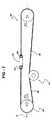
図1を参照すると、自動車10が、部分的に切除された状態で示されている。自動車10は、これ又部分的に切除された状態で示されているスライディングドア12を有している。全体が符号14で示されたスライディングドア駆動組立体が、自動車10に取り付けられると共にスライディングドア12に作動的に連結されている。取付けブラケット16が、スライディングドア駆動組立体14を自動車10に取り付けている。理解されるように、取付けブラケットは、実際には、スライディングドア駆動組立体14を自動車10に取り付ける以外の機能を備えた自動車10の別の構造体であるのが良い。 Referring to FIG. 1, an
スライディングドア駆動組立体14は、電気プラグ20により図示的に表された電気エネルギー源に電気的に接続されたモータ18を有する。モータ18は、自動車プロトコルにおいて標準の電気エネルギーを用いて動作することが想定されている。モータ18は、出力シャフト22(図3)の二方向における回転を考慮に入れて双方向である。出力シャフト22は、全体が符号24で示された伝動装置の出力シャフトとして示されている。 The sliding door drive assembly 14 includes a
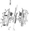
図2〜図4を参照すると、伝動装置24は、モータ18に作動的に連結され、モータ18の回転力を出力シャフト22に伝達している。伝動装置24は、モータ18とインライン関係をなした歯車装置26を有し、この歯車装置は、モータ18の回転出力をスライディングドア駆動組立体14に適した何らかの手段に変換してスライディングドア12が完全開放位置と完全閉鎖位置との間で図1に符号Aで示されている長手方向軸線の方向に動くことができるようにするのに必要な機械的利点を提供するために用いられる。伝動装置24は、2つの歯付きベルトプーリ28,30及びこれらの周りに延びる歯付きベルト32を有する。ベルトプーリのうちの一方28は、第1の軸線回りに歯車装置26と一緒に回転する。他方のベルトプーリ30は、第2の軸線回りに出力シャフトと一緒に回転する。第2の軸線は、第1の軸線とは異なっている。歯付きベルトプーリ28,30は、モータ18の回転出力の方向を変えるために用いられる。これは、回転力をスライディングドア駆動組立体14の長さに関する要件を極力緩和する位置に逆戻りさせることによりスライディングドア組立体14のコンパクトなパッケージングを容易にする。歯付きベルト32は、電気モータ18とスライディングドア12との間に延びた状態で振動を減衰させるために用いられる。 2 to 4, the
図4を参照すると、伝動装置24は、全体が符号34で示されたクラッチを更に有する。クラッチ34により、スライディングドア12をモータ18から切り離すことができる。クラッチ34は、スライディングドア駆動組立体14によりスライディングドア12をその完全開放位置と完全閉鎖位置との間で作動させるのではなく、万一スライディングドア12を手動で動かすことが望ましい場合、スライディングドア12を手動で動かすのに必要な労力を軽減する。クラッチ34は、一対の歯付きプレート35,37を有している。歯付きプレート35,37は、クラッチ34により必要な空間を最小限に抑えるために用いられている。具体的に説明すると、クラッチ34は、クラッチ34により利用されるプレート35,37が歯付きであるこということにより減少した直径を有する。 Referring to FIG. 4, the
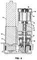
スライディングドア駆動組立体14は、継手38によりクラッチ34に結合されたケーブルドラム36を有している。ケーブルドラム36は、ケーブルドラムハウジング44に固着されている2組の軸受40,42により定位置に保持されている。ケーブルドラム36は、第1のケーブル48及び第2のケーブル50が巻き付けられる螺旋溝46を有している。第1のケーブル48及び第2のケーブル50は、螺旋溝46に入れられた状態で互いに逆方向にケーブルドラム36に巻き付けられる。図1を参照すると、第1のケーブル48は、ケーブルドラム36から長手方向軸線Aの方向において前側プーリ52まで前方に延び、しかる後、第1のケーブル48は、スライディングドア12に向かって逆向きになっている。第2のケーブル50は、ケーブルドラム36から長手方向軸線Aの方向において後側プーリ54まで後方に延び、しかる後、第2のケーブル50は、スライディングドア12に向かって逆向きになっている。第1のケーブル48及び第2のケーブル50は、それぞれ、センターヒンジ56に固着されており、このセンターヒンジは、スライディングドア12に固着されている。ケーブルドラム36の回転により、第1のケーブル48及び第2のケーブル50のうちの一方が巻き取られ、それと同時に第1のケーブル48及び第2のケーブル50のうちの他方が繰り出される。 The sliding door drive assembly 14 has a
センターヒンジ56は、第1のケーブル48及び第2のケーブル50をそれぞれセンターヒンジ56に固定するための前方ケーブル終端固定具58及び後方ケーブル終端固定具60を有している。前方ケーブル終端固定具58及び後方ケーブル終端固定具60は、それぞれ、前方ケーブルテンショナ62及び後方ケーブルテンショナ64を有している。前方ケーブルテンショナ62及び後方ケーブルテンショナ64は、それぞれ、第1のケーブルの48及び第2のケーブル50を張力調整する。 The
ケーブルドラムハウジング44は、ケーブルドラム36及びケーブルドラムハウジング44からケーブルドラム36の接線方向に延び出た支持ガイド66,68を有する。支持ガイド66,68は、第1のケーブル48及び第2のケーブル50を、摩擦力を最小限に抑える経路に沿ってケーブルドラム36から外方に且つこれから遠ざけるよう案内する。支持ガイド66,68は、ケーブルの経路の向きを変えるのに必要なプーリの個数を最小限に抑えることにより摩擦力を最小限に抑える第1のケーブル48及び第2のケーブル50のための経路を定めている。これにより、部品数が減少すると共にスライディングドア駆動組立体14に打ち勝つのに必要な摩擦力が減少する。支持ガイド66,68は又、スライディングドア駆動組立体14の作動中、第1のケーブル48及び第2のケーブル50を案内してケーブルドラム36に掛けたり外したりするのを助け、それによりケーブルがジャンプして螺旋溝46から出るのが阻止されるということが意図されている。ケーブルは、スライディングドア12が移動行程の真ん中に位置しているとき、ケーブルドラム36の螺旋溝46の螺旋角(図5ではαで示されている)に平行であることは理解されよう。 The
支持ガイド66,68は、取付けブラケット16によりスライディングドア駆動組立体14を自動車10に取り付けるために用いられる取付け孔76,78を更に有している。支持ガイド66,68は、スライディングドア駆動組立体14の構造的支持手段となり、スライディングドア駆動組立体14をその全ての一体部品と共に支持している。支持ガイド66,68は、追加の剛性をスライディングドア駆動組立体14にもたらす補強リブ80,82を有している。 The support guides 66, 68 further include mounting holes 76, 78 that are used to mount the sliding door drive assembly 14 to the
図5を参照すると、全体を符号70で示された位置センサが、ケーブルドラム36の回転位置を突き止めるためにケーブルドラムハウジング44に取り付けられている。位置センサ70は、解像度が非常に高い位置センサであり、かかる位置センサは、ケーブルドラム36に固着され、これと一緒に回転する磁石74の向きを検出するセンサ72を含む。 Referring to FIG. 5, a position sensor, generally designated 70, is attached to the
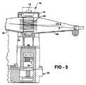
図6及び図7を参照すると(図中、上述したのとほぼ同じ要素は、同一参照符号にプライム記号(′)を付けて示されている)、本発明の第2の実施形態では、センターヒンジ56′の前方ケーブル終端固定具58′及び後方ケーブル終端固定具60′は、第1の実施形態において開示したようなケーブルテンショナを備えていない。これとは異なり、スライディングドア駆動組立体14′は、全体が符号84で示されたばね押し前側プーリ組立体及び全体が符号86で示されたばね押し後側プーリ組立体を有している。前側プーリ組立体84及び後側プーリ組立体86は、以下に説明するように、それぞれ第1のケーブル48′及び第2のケーブル50′を張力調整する。 Referring to FIGS. 6 and 7 (in the figures, substantially the same elements as those described above are shown with the same reference numerals followed by a prime symbol (′)), in the second embodiment of the present invention, the center The front cable end fixture 58 'and the rear cable end fixture 60' of the hinge 56 'do not include the cable tensioner as disclosed in the first embodiment. In contrast, the sliding door drive assembly 14 ′ includes a spring-loaded front pulley assembly generally designated 84 and a spring-loaded rear pulley assembly generally designated 86. The
前側プーリ組立体84だけが詳細に示されているが、理解されるように、前側プーリ組立体84と後側プーリ組立体86の両方は、実質的に同一であることは理解されよう。図示の実施形態では、前側プーリ組立体84及び後側プーリ組立体86はそれぞれ、上側ハウジング部分88及び下側ハウジング部分90を有している。上側ハウジング部分88と下側ハウジング部分90を組み立てると、これらの間には、前側プーリ52′及び後側プーリ54′のうちの一方を受け入れるキャビティ92が形成される。上側ハウジング部分88及び下側ハウジング部分90は、それぞれ、第1のケーブル48′及び第2のケーブル50′を案内してキャビティ92に出し入れする開口部93,95を画定している。上側ハウジング部分88と下側ハウジング部分90は、複数個の締結具94、例えばねじ、ボルト又はリベットを用いて互いに固着されている。上側ハウジング部分88及び下側ハウジング部分90は、自動車10′に固着されるようになっている。具体的に説明すると、上側ハウジング部分88及び下側ハウジング部分90は、それぞれ、前側プーリ組立体84及び後側プーリ組立体86をそれぞれ自動車10′に固着するための締結具(図示せず)を挿通状態で受け入れる孔又はスロット96を有している。スロット96は、長手方向軸線Aの方向における前側プーリ組立体84及び後側プーリ組立体86のそれぞれの位置調整を考慮に入れて細長い。 Although only the
前側プーリ組立体84を参照すると、前側プーリ52′は、上側ハウジング部分88と下側ハウジング部分90との間でキャビティ92内に配置されている。前側プーリ52′は、シャフト98で回転可能に支承されている。一対の互いに反対側に位置するエンドキャップ100が、シャフト98の互いに反対側の端部を受け入れている。エンドキャップ100は、上側ハウジング部分88及び下側ハウジング部分90にそれぞれ形成され、長手方向軸線Aの方向に延びる一対の対向した溝102内に配置されている。エンドキャップ100は、溝102に沿って長手方向軸線Aの方向に摺動可能に動くことができる。 With reference to the
コイルばね104が、エンドキャップ100の各々と上側ハウジング部分88及び下側ハウジング部分90のそれぞれとの間に延びている。図示の実施形態では、各エンドキャップ100からは、ばね104のうちの一方の第1の端部を軸方向に受け入れるポスト106が延びている。理解されるように、上側ハウジング部分88及び下側ハウジング部分90のそれぞれからは、ばね104のうちの一方の第2の端部を軸方向に受け入れる同様なポストが延びているのが良い。ばね104は、前側プーリ52′を図7において矢印F1により示されているように、自動車10′の前方端部に向かって前方に付勢し、それにより第1のケーブル48′を張力調整する。同様に、後側プーリ組立体86に関し、ばね104は、後側プーリ54′を図7において矢印F2により示されているように、自動車10′の後方端部に向かって後方に付勢し、それにより第2のケーブル50′を張力調整する。 A
図8を参照すると(図中、上述したのとほぼ同じ要素は、同一参照符号にダブルプライム記号(″)を付けて示されている)、本発明の第2の実施形態では、モータ18″、歯車装置26″、伝動装置24″、出力シャフト22″及びケーブルドラム36″が、ハウジング108とカバー110との間に配置されている。ハウジング108とカバー110は、互いに固着され、これらは、第1のケーブル48″及び第2のケーブル50″を案内するために外方に延びた支持ガイド66″,68″を有している。 Referring to FIG. 8 (in the figure, substantially the same elements as described above are shown with the same reference number followed by a double prime symbol (")), in the second embodiment of the present invention, the
全体を符号112で示された位置エンコーダが、スライディングドア駆動組立体14″に作動的に結合されている。位置エンコーダ112は、遊星歯車装置116により出力シャフト22″に作動的に結合された二極磁石114を有し、この遊星歯車装置は、スライディングドア12″のその完全開放位置とその完全閉鎖位置との間における全移動量が二極磁石114の1回転以下に相当するよう歯車結合されている。位置エンコーダ112は、4つの一体形ホールセンサ(Hall sensor)120を備えたプリント回路板118を更に有している。プリント回路板118は、ハウジング108に取り付けられるようになっており、このプリント回路板は、二極磁石114の回転位置を検出する。かくして、位置エンコーダ112は、スライディングドア12″が手動で新たな位置まで動かされる動力切り離し期間後であっても、二極磁石114のその1回転以内における回転位置をこの位置エンコーダが常時知っているという点において「絶対」である。この場合、二極磁石114の回転位置を完全開放位置と完全閉鎖位置との間におけるスライディングドア12″の位置に相関させる。 A position encoder, indicated generally at 112, is operatively coupled to the sliding door drive assembly 14 ". The
本発明を例示的に説明した。用いた用語は、性質上、説明のための用語であり、本発明を限定するものではないことは理解されるべきである。上記教示に照らして本発明の多くの改造例及び変形例が可能である。したがって、本発明は、特許請求の範囲に記載された本発明の範囲内において、具体的に説明した形態以外の形態で実施できる。 The invention has been described by way of example. It is to be understood that the terms used are descriptive terms in nature and do not limit the invention. Many modifications and variations of the present invention are possible in light of the above teachings. Therefore, the present invention can be carried out in forms other than those specifically described within the scope of the present invention described in the claims.
Claims (30)
Translated fromJapanese前記電気エネルギー源に電気的に接続されたモータを有し、前記モータは、電気エネルギーを回転力に変換し、
前記モータに作動的に連結され、前記回転力を出力シャフトに伝達する伝動装置を有し、
前記出力シャフトに固着され、前記出力シャフトと一緒に回転するケーブルドラムを有し、
前記ケーブルドラムに互いに逆方向に巻き付けられた第1及び第2のケーブルを有し、前記第1のケーブルは、前記ケーブルドラムから前記スライディングドアに沿って前方に延び、前記第2のケーブルは、前記ケーブルドラムから前記スライディングドアに沿って後方に延び、
前記ケーブルドラムから接線方向に延び、前記第1及び前記第2のケーブルを、摩擦力を最小限に抑える経路に沿って前記ケーブルドラムから外方に且つ遠ざかって案内する支持ガイドを有し、
前記自動車に取り付けられると共に前記第1及び前記第2のケーブルを張力調整するために前記スライディングドア駆動組立体と前記スライディングドアとの間で前記第1及び前記第2のケーブルに作動的に結合された前側及び後側プーリ組立体を有する、スライディングドア駆動組立体。An automotive sliding door drive assembly comprising an electrical energy source and a sliding door, the sliding door drive assembly comprising:
A motor electrically connected to the electrical energy source, the motor converting electrical energy into rotational force;
A transmission device operatively coupled to the motor for transmitting the rotational force to an output shaft;
A cable drum secured to the output shaft and rotating together with the output shaft;
The cable drum includes first and second cables wound in opposite directions, the first cable extending forward from the cable drum along the sliding door, and the second cable is Extending rearward from the cable drum along the sliding door;
A support guide extending tangentially from the cable drum and guiding the first and second cables outward and away from the cable drum along a path that minimizes frictional forces;
The first and second cables are operatively coupled between the sliding door drive assembly and the sliding door for tensioning the first and second cables attached to the vehicle. A sliding door drive assembly having front and rear pulley assemblies.
キャビティを画定するハウジングを有し、
前記キャビティ内に配置され、シャフトで回転可能に支承されたプーリを有し、前記ケーブルは、前記スライディングドア駆動組立体と前記スライディングドアとの間で前記プーリの一部分に巻き付けられ、
前記シャフトの互いに反対側の端部を受け入れると共に前記ハウジングに形成され且つ長手方向に延びる対向した溝内に摺動可能に配置された一対のエンドキャップを有し、
前記エンドキャップと前記ハウジングとの間に延び、前記プーリを前記スライディングドア駆動組立体から長手方向に押し離す一対のばねを有する、ケーブルテンショナ。A cable tensioner for tensioning a cable extending between and operatively coupled to a sliding door drive assembly and a sliding door, the cable tensioner comprising:
Having a housing defining a cavity;
A pulley disposed within the cavity and rotatably supported by a shaft, wherein the cable is wound around a portion of the pulley between the sliding door drive assembly and the sliding door;
A pair of end caps for receiving opposite ends of the shaft and slidably disposed in opposing grooves formed in the housing and extending longitudinally;
A cable tensioner having a pair of springs extending between the end cap and the housing to push the pulley longitudinally away from the sliding door drive assembly.
前記電気エネルギー源に電気的に接続されたモータを有し、前記モータは、電気エネルギーを回転力に変換し、
前記モータに作動的に連結され、前記回転力を出力シャフトに伝達する伝動装置を有し、
前記出力シャフトに固着され、前記出力シャフトと一緒に回転するケーブルドラムを有し、
前記スライディングドア駆動組立体の少なくとも一部分を覆ったハウジングを有し、
前記ケーブルドラムに互いに逆方向に巻き付けられた第1及び第2のケーブルを有し、前記第1のケーブルは、前記ケーブルドラムから前記スライディングドアに沿って前方に延び、前記第2のケーブルは、前記ケーブルドラムから前記スライディングドアに沿って後方に延び、
前記ケーブルドラムから接線方向に延び、前記第1及び前記第2のケーブルを、摩擦力を最小限に抑える経路に沿って前記ケーブルドラムから外方に且つ遠ざかって案内する支持ガイドを有し、
前記スライディングドア駆動組立体に作動的に結合された絶対位置エンコーダを有し、前記絶対位置エンコーダは、前記出力シャフトに作動的に結合された二極磁石と、前記伝動装置に取り付けられるようになり、前記磁石の回転位置を検出する4つの一体形ホールセンサを備えたプリント回路板とを有し、完全開放位置と完全閉鎖位置との間における前記スライディングドアの全移動量は、前記磁石の1回転以下に相当し、前記磁石の前記回転位置は、前記完全開放位置と前記完全閉鎖位置との間における前記スライディングの位置と相関するようになっている、スライディングドア駆動組立体。An automotive sliding door drive assembly comprising an electrical energy source and a sliding door, the sliding door drive assembly comprising:
A motor electrically connected to the electrical energy source, the motor converting electrical energy into rotational force;
A transmission device operatively coupled to the motor for transmitting the rotational force to an output shaft;
A cable drum secured to the output shaft and rotating together with the output shaft;
A housing covering at least a portion of the sliding door drive assembly;
The first and second cables are wound around the cable drum in opposite directions, the first cable extends forward from the cable drum along the sliding door, and the second cable includes: Extending rearward from the cable drum along the sliding door,
A support guide extending tangentially from the cable drum and guiding the first and second cables outward and away from the cable drum along a path that minimizes frictional forces;
An absolute position encoder operably coupled to the sliding door drive assembly, wherein the absolute position encoder is attached to the transmission and a dipole magnet operatively coupled to the output shaft; A printed circuit board having four integrated Hall sensors for detecting the rotational position of the magnet, and the total amount of movement of the sliding door between the fully open position and the fully closed position is 1 of the magnet. A sliding door drive assembly, corresponding to rotation below, wherein the rotational position of the magnet is adapted to correlate with the position of the sliding between the fully open position and the fully closed position.
前記スライディングドア駆動組立体の出力シャフトに作動的に結合された二極磁石を有し、完全開放位置と完全閉鎖位置との間における前記スライディングドアの全移動量が、前記二極磁石の1回転以下に相当するようになっており、
前記スライディングドア駆動組立体のハウジングに取り付けられるようになったプリント回路板を有し、前記プリント回路板は、前記二極磁石の前記回転位置が前記完全開放位置と前記完全閉鎖位置との間における前記スライディングドアの前記位置と相関するよう前記1回転以内における前記二極磁石の回転位置を検出する4つの一体形ホールセンサを有する、絶対位置エンコーダ。An absolute position encoder for locating a sliding door on a vehicle having a sliding door drive assembly, the absolute position encoder comprising:
A dipole magnet operatively coupled to the output shaft of the sliding door drive assembly, wherein the total travel of the sliding door between a fully open position and a fully closed position is one rotation of the dipole magnet; It corresponds to the following,
A printed circuit board adapted to be attached to a housing of the sliding door drive assembly, wherein the printed circuit board has a rotational position of the dipole magnet between the fully open position and the fully closed position; An absolute position encoder having four integrated Hall sensors for detecting the rotational position of the dipole magnet within one rotation so as to correlate with the position of the sliding door.
Applications Claiming Priority (2)
| Application Number | Priority Date | Filing Date | Title |
|---|---|---|---|
| US11/680,285US7770961B2 (en) | 2006-02-20 | 2007-02-28 | Compact cable drive power sliding door mechanism |
| PCT/CA2008/000389WO2008104080A1 (en) | 2007-02-28 | 2008-02-28 | Compact cable drive power sliding door mechanism |
Publications (1)
| Publication Number | Publication Date |
|---|---|
| JP2010519443Atrue JP2010519443A (en) | 2010-06-03 |
Family
ID=39735388
Family Applications (1)
| Application Number | Title | Priority Date | Filing Date |
|---|---|---|---|
| JP2009551087APendingJP2010519443A (en) | 2007-02-28 | 2008-02-28 | Compact cable-driven power sliding door mechanism |
Country Status (5)
| Country | Link |
|---|---|
| US (2) | US7770961B2 (en) |
| JP (1) | JP2010519443A (en) |
| CN (3) | CN101657598B (en) |
| CA (1) | CA2679150A1 (en) |
| WO (1) | WO2008104080A1 (en) |
Cited By (1)
| Publication number | Priority date | Publication date | Assignee | Title |
|---|---|---|---|---|
| US9850697B2 (en) | 2015-12-03 | 2017-12-26 | Korea Electrical Power Corporation | Safety power window system and operation method thereof |
Families Citing this family (48)
| Publication number | Priority date | Publication date | Assignee | Title |
|---|---|---|---|---|
| DE102004028760A1 (en)* | 2004-06-16 | 2006-01-12 | Kiekert Ag | Drive device for a motor vehicle door, in particular a sliding door |
| US7770961B2 (en)* | 2006-02-20 | 2010-08-10 | Magna Closures Inc. | Compact cable drive power sliding door mechanism |
| US7547058B2 (en)* | 2006-05-15 | 2009-06-16 | Ford Global Technologies, Llc | System and method for operating an automotive liftgate |
| US7992460B2 (en)* | 2006-09-09 | 2011-08-09 | Stabilus Gmbh | Drive device |
| JP5207678B2 (en)* | 2007-07-20 | 2013-06-12 | 株式会社ハイレックスコーポレーション | Cable guide and sliding door drive using the same |
| JP4447633B2 (en)* | 2007-11-07 | 2010-04-07 | 三井金属鉱業株式会社 | Automatic opening / closing device for vehicle sliding door |
| DE202007016273U1 (en)* | 2007-11-20 | 2009-04-02 | Gebr. Bode Gmbh & Co. Kg | Drive system for entry and exit devices with improved position detection |
| JP2009127290A (en)* | 2007-11-22 | 2009-06-11 | Aisin Seiki Co Ltd | Vehicle door opening and closing device |
| AU2011101477B4 (en)* | 2007-12-20 | 2012-06-28 | Automatic Technology (Australia) Pty Ltd | Sensing the position of a door |
| WO2009079685A1 (en)* | 2007-12-20 | 2009-07-02 | Smart Openers Pty Ltd | Sensing the position of a door |
| DE202008001066U1 (en)* | 2008-01-24 | 2009-06-18 | Gebr. Bode Gmbh & Co. Kg | Rotational position sensing device |
| CN102946767B (en) | 2010-05-28 | 2016-11-23 | 亨特道格拉斯公司 | The architectural opening shelter of power is provided by turning motor |
| JP2014507586A (en)* | 2011-02-25 | 2014-03-27 | マグナ クロージャーズ インコーポレイテッド | Drive assembly for vehicle power sliding door |
| GB2492774A (en)* | 2011-07-11 | 2013-01-16 | Ford Global Tech Llc | Actuation mechanism for a sliding door of a motor vehicle |
| CN103732845B (en) | 2011-07-27 | 2016-09-28 | 麦格纳覆盖件有限公司 | Electric rotary door actuator |
| DE102011083418A1 (en)* | 2011-09-26 | 2013-03-28 | Bayerische Motoren Werke Aktiengesellschaft | motor vehicle |
| WO2013052083A1 (en) | 2011-10-03 | 2013-04-11 | Hunter Douglas Inc. | Methods and apparatus to control architectural opening covering assemblies |
| CN103075068A (en)* | 2011-10-25 | 2013-05-01 | 昆山麦格纳汽车系统有限公司 | Sliding door open/close drive mechanism |
| CN103072452A (en)* | 2011-10-25 | 2013-05-01 | 昆山麦格纳汽车系统有限公司 | Opening and closing driving mechanism with improved structure for automobile sliding door |
| JP5712952B2 (en)* | 2012-03-01 | 2015-05-07 | アイシン精機株式会社 | Vehicle door opening and closing device |
| CA2828819C (en) | 2012-10-03 | 2020-03-10 | Hunter Douglas Inc. | Methods and apparatus to control an architectural opening covering assembly |
| JP5796238B2 (en)* | 2014-02-07 | 2015-10-21 | 三井金属アクト株式会社 | Opening and closing device for vehicle door |
| US9103373B1 (en) | 2014-04-30 | 2015-08-11 | Hi-Lex Controls, Inc. | Bearing-shaft assembly with bearing and method of attaching a bearing to a shaft |
| US9776483B2 (en) | 2014-11-24 | 2017-10-03 | Magna Closures Inc. | Electromechanical strut with motor-gearbox assembly having dual stage planetary gearbox |
| US10100568B2 (en)* | 2015-08-12 | 2018-10-16 | Magna Closures Inc. | Electromechanical strut with lateral support feature |
| DE102015215631A1 (en) | 2015-08-17 | 2017-02-23 | Brose Fahrzeugteile Gmbh & Co. Kommanditgesellschaft, Bamberg | Device for manual and / or electromotive adjustment or locking of a first vehicle part and a second vehicle part relative to each other |
| DE102015215627A1 (en) | 2015-08-17 | 2017-02-23 | Brose Fahrzeugteile Gmbh & Co. Kommanditgesellschaft, Bamberg | Device for manual and / or electromotive adjustment or locking of a first vehicle part and a second vehicle part relative to each other |
| DE102015215630A1 (en) | 2015-08-17 | 2017-02-23 | Brose Fahrzeugteile Gmbh & Co. Kommanditgesellschaft, Bamberg | Device for manual and / or electromotive adjustment or locking of a first vehicle part and a second vehicle part relative to each other |
| US10648231B2 (en) | 2016-01-14 | 2020-05-12 | Hunter Douglas, Inc. | Methods and apparatus for controlling architectural opening coverings in more than one mode |
| CN106004374B (en)* | 2016-06-24 | 2018-07-06 | 芜湖莫森泰克汽车科技股份有限公司 | Structure drag-line strainer is driven in power-operated sliding door |
| DE102016218225A1 (en)* | 2016-09-22 | 2018-03-22 | Stabilus Gmbh | Spindle drive means |
| DE102017203008A1 (en) | 2017-02-24 | 2018-08-30 | Ford Global Technologies, Llc | Cable guide arrangement for a power-operated vehicle sliding door |
| US10801593B2 (en) | 2017-04-26 | 2020-10-13 | Paratech, Incorporated | Strut extender mechanism |
| CN107023240A (en)* | 2017-05-31 | 2017-08-08 | 芜湖莫森泰克汽车科技股份有限公司 | A kind of power-operated sliding door drive device |
| US10443289B2 (en)* | 2017-06-27 | 2019-10-15 | GM Global Technology Operations LLC | Vehicle with power swinging door and position-based torque compensation method |
| US11855581B2 (en) | 2017-07-18 | 2023-12-26 | Polar Racking Inc. | Solar panel support and drive system |
| DE102018118126A1 (en)* | 2018-07-26 | 2020-01-30 | Brose Fahrzeugteile Gmbh & Co. Kommanditgesellschaft, Bamberg | Drive arrangement for motorized adjustment of a flap of a motor vehicle |
| CN110857128A (en)* | 2018-08-23 | 2020-03-03 | 福州明芳汽车部件工业有限公司 | Vehicle door cover opening and closing mechanism |
| US11261646B2 (en) | 2018-09-24 | 2022-03-01 | Magna Closures Inc. | Clutch assembly for powered door system |
| DE102019107709A1 (en)* | 2019-03-26 | 2020-10-01 | Kiekert Aktiengesellschaft | SLIDING DOOR OPERATOR FOR A MOTOR VEHICLE |
| DE102019107716A1 (en)* | 2019-03-26 | 2020-10-01 | Kiekert Aktiengesellschaft | SLIDING DOOR OPERATOR FOR A MOTOR VEHICLE |
| DE112020001896T5 (en) | 2019-04-10 | 2021-12-23 | Magna Closures Inc. | DIRECT DRIVE WITH ROPE OPERATION ACTUATION SYSTEM FOR A LOCKING PLATE |
| CN112211519A (en) | 2019-07-09 | 2021-01-12 | 昆山麦格纳汽车系统有限公司 | Closure panel balancing mechanism with threaded connection |
| CN114222846B (en)* | 2019-07-26 | 2023-07-11 | 麦格纳覆盖件有限公司 | Dual spool drive unit for sliding door |
| CN215257364U (en) | 2021-02-09 | 2021-12-21 | 麦格纳汽车系统(苏州)有限公司 | Anisotropic and anisotropic damping device and electric telescopic mechanism |
| US20220290482A1 (en)* | 2021-03-10 | 2022-09-15 | Hi-Lex Controls, Inc. | Split-axis power strut |
| CN114087973A (en)* | 2021-12-09 | 2022-02-25 | 中国船舶重工集团公司第七0三研究所 | Device for simultaneously measuring displacement of two sliding parts of large clutch |
| DE102024109750B3 (en) | 2024-04-08 | 2025-04-24 | Dr. Ing. H.C. F. Porsche Aktiengesellschaft | Arrangement comprising an assembly for a motor vehicle and at least one cable drive, as well as motor vehicle |
Citations (6)
| Publication number | Priority date | Publication date | Assignee | Title |
|---|---|---|---|---|
| JP2001220946A (en)* | 1999-12-03 | 2001-08-17 | Nippon Cable Syst Inc | Pull-cable type opening/closing device for sunroof and the like |
| JP2003301659A (en)* | 2002-04-08 | 2003-10-24 | Oi Seisakusho Co Ltd | Cable tension device of movable body |
| WO2004009939A1 (en)* | 2002-07-18 | 2004-01-29 | Sonnie Hermansson | An apparatus for opening and closing a sliding door |
| JP2004100345A (en)* | 2002-09-12 | 2004-04-02 | Mitsuba Corp | Automatic switchgear for vehicles |
| JP2004257008A (en)* | 2003-02-24 | 2004-09-16 | Mitsubishi Cable Ind Ltd | Automatic opening/closing system for slide door, and automobile equipped with the same |
| US20040216383A1 (en)* | 2003-03-19 | 2004-11-04 | Rogers Lloyd W | Apparatus and method for providing a sliding door mechanism |
Family Cites Families (56)
| Publication number | Priority date | Publication date | Assignee | Title |
|---|---|---|---|---|
| US3320373A (en)* | 1964-08-04 | 1967-05-16 | Blaw Knox Co | Positive timing device with infinite setting |
| US3287618A (en)* | 1965-08-04 | 1966-11-22 | Dalton Foundries Inc | Closure operator |
| GB2164090B (en) | 1984-07-26 | 1987-10-14 | Ohi Seisakusho Co Ltd | Automatic sliding door system for vehicles |
| US4934203A (en)* | 1989-01-06 | 1990-06-19 | Bailey Thomas R | Power arm |
| JPH02252878A (en)* | 1989-03-24 | 1990-10-11 | Toyo Sash Co Ltd | Driving device for door body |
| US4952080A (en)* | 1989-05-12 | 1990-08-28 | The Stanley Works | Automatic assist for swing-door operator |
| JPH03209042A (en)* | 1990-01-08 | 1991-09-12 | Koito Mfg Co Ltd | Elevating and sinking device |
| US5138795A (en) | 1990-04-25 | 1992-08-18 | General Motors Corporation | Power sliding door closer |
| US5319881A (en) | 1993-01-25 | 1994-06-14 | General Motors Corporation | Sliding door closed loop cable closure system with balanced cable length and varying diameter pulleys |
| US5316365A (en) | 1993-01-25 | 1994-05-31 | General Motors Corporation | Sliding door closed loop cable closure system with balanced cable tension and varying diameter pulleys |
| US5787636A (en)* | 1995-12-20 | 1998-08-04 | Itt Automotive Electrical Systems, Inc. | Power drive for a movable closure with ball nut driven flexible cable |
| US5913563A (en) | 1996-04-04 | 1999-06-22 | Mitsui Kinzoku Kogyo Kabushiki Kaisha | Powered sliding device for vehicle sliding door |
| US5809833A (en)* | 1996-09-24 | 1998-09-22 | Dana Corporation | Linear actuator |
| US5813171A (en)* | 1996-11-18 | 1998-09-29 | Truth Hardware Corporation | Integrated power window operator |
| JP3656787B2 (en) | 1997-01-30 | 2005-06-08 | 株式会社大井製作所 | Automatic opening / closing device for vehicle sliding door |
| GB2323124B (en) | 1997-03-11 | 2000-12-06 | Delphi Automotive Systems Gmbh | Electrically operated slidable door actuator |
| DE19727603C1 (en) | 1997-06-28 | 1998-07-23 | Kiekert Ag | Motorised vehicle with at least one sliding door and door=drive mechanism |
| US5982169A (en)* | 1997-09-24 | 1999-11-09 | Eastman Kodak Company | Micro-encoder with molded micro-magnet |
| DE19806762B4 (en) | 1998-02-18 | 2009-03-12 | Volkswagen Ag | Actuating device for a sliding door, in particular for motor vehicles |
| DE19819421C2 (en)* | 1998-04-30 | 2001-11-08 | Kiekert Ag | Sliding door drive for the sliding door of a motor vehicle |
| CA2364940C (en) | 1999-03-08 | 2008-03-25 | Atoma International Corp. | Drive mechanism for selectively opening and closing a closure panel manually or automatically |
| US6118243A (en)* | 1999-04-07 | 2000-09-12 | Overhead Door Corporation | Door operator system |
| US6038818A (en) | 1999-04-30 | 2000-03-21 | General Motors Corporation | Actuator assembly for a powered sliding door system |
| JP2001031350A (en)* | 1999-07-23 | 2001-02-06 | Toshiba Corp | Hoisting device and elevator device |
| JP2001115737A (en)* | 1999-10-18 | 2001-04-24 | Koito Mfg Co Ltd | Safety device for power window |
| DE10001054B4 (en)* | 1999-12-08 | 2015-08-20 | Witte-Velbert Gmbh & Co. Kg | hinge assembly |
| JP3855600B2 (en) | 2000-05-29 | 2006-12-13 | アイシン精機株式会社 | Sliding door device for vehicle |
| US6802154B1 (en)* | 2000-06-23 | 2004-10-12 | Multimatic, Inc. | Automatic sliding door opening and closing system with a releasing mechanism for fixably and releasably attaching a vehicle door to a belt drive system |
| US6390535B1 (en) | 2000-09-11 | 2002-05-21 | Delphi Technologies, Inc. | Sliding door closure apparatus |
| US6553719B1 (en) | 2000-10-13 | 2003-04-29 | Hi-Lex Corporation | Door mounted power sliding door mechanism |
| US6460295B1 (en) | 2000-10-19 | 2002-10-08 | Delphi Technologies, Inc. | Electrically operated closure actuator |
| WO2002087912A1 (en)* | 2001-04-26 | 2002-11-07 | Litens Automotive | Powered liftgate opening mechanism and control system |
| CA2468643C (en)* | 2001-11-29 | 2010-11-23 | Intier Automotive Closures Inc. | Drive assembly for a power closure panel |
| JP3928155B2 (en)* | 2002-05-13 | 2007-06-13 | 株式会社大井製作所 | Driving device for slide opening / closing body |
| CN2556843Y (en)* | 2002-06-18 | 2003-06-18 | 上海安乃达驱动技术有限公司 | Brushless dc otor for electric motor car |
| US6925757B2 (en) | 2002-10-02 | 2005-08-09 | Delphi Technologies, Inc. | Cable drive assembly |
| CN1732723A (en)* | 2002-12-27 | 2006-02-08 | Fci亚洲技术有限公司 | plate fixture |
| JP4218403B2 (en)* | 2003-04-21 | 2009-02-04 | アイシン精機株式会社 | Vehicle door control device |
| DE10332026A1 (en)* | 2003-07-15 | 2005-02-03 | Daimlerchrysler Ag | Door arrangement for a motor vehicle |
| JP4545409B2 (en)* | 2003-09-11 | 2010-09-15 | 株式会社ミツバ | Opening and closing device for vehicle |
| FI114815B (en)* | 2003-09-18 | 2004-12-31 | Abloy Oy | Improved arrangement for swing door apparatus, has coupling units arranged between operating shaft of actuator and shaft section of worm shaft to disconnect force transmitting connection between actuator and shaft section of worm shaft |
| IL159533A0 (en) | 2003-12-23 | 2009-02-11 | Pixman Corp | Electrically-operated sliding door mechanism |
| CA2514670A1 (en)* | 2004-08-06 | 2006-02-06 | Magna Closures Inc. | Electromechanical strut |
| WO2006067420A1 (en)* | 2004-12-20 | 2006-06-29 | Mark Anthony Howard | Inductive position sensor |
| JP2006207300A (en)* | 2005-01-28 | 2006-08-10 | Aisin Seiki Co Ltd | Vehicle door opening and closing device |
| WO2006086892A1 (en)* | 2005-02-18 | 2006-08-24 | Magna Closures Inc. | Compact cable drive power sliding door mechanism |
| JP2006348668A (en)* | 2005-06-17 | 2006-12-28 | Mitsuba Corp | Sliding door opening and closing device |
| WO2007006313A1 (en)* | 2005-07-13 | 2007-01-18 | Linak A/S | Actuator with means for determining the position of an activation element |
| US7802664B2 (en)* | 2005-11-02 | 2010-09-28 | Dura Global Technologies, Llc | Power strut assembly |
| US7770961B2 (en)* | 2006-02-20 | 2010-08-10 | Magna Closures Inc. | Compact cable drive power sliding door mechanism |
| GB2450301B (en)* | 2006-04-27 | 2011-07-27 | Stoneridge Control Devices Inc | Steering shaft lock actuator |
| US20070261306A1 (en)* | 2006-05-11 | 2007-11-15 | Hanna Ronald J | Liftgate drive unit having integral motor and assist |
| US7547058B2 (en)* | 2006-05-15 | 2009-06-16 | Ford Global Technologies, Llc | System and method for operating an automotive liftgate |
| US7624657B2 (en)* | 2006-07-12 | 2009-12-01 | Thermotion Corporation | Motor-driven actuator |
| US7992460B2 (en)* | 2006-09-09 | 2011-08-09 | Stabilus Gmbh | Drive device |
| JP5207678B2 (en)* | 2007-07-20 | 2013-06-12 | 株式会社ハイレックスコーポレーション | Cable guide and sliding door drive using the same |
- 2007
- 2007-02-28USUS11/680,285patent/US7770961B2/enactiveActive
- 2008
- 2008-02-28CNCN200880012183.1Apatent/CN101657598B/enactiveActive
- 2008-02-28WOPCT/CA2008/000389patent/WO2008104080A1/enactiveApplication Filing
- 2008-02-28CNCN201410085717.0Apatent/CN103821425B/enactiveActive
- 2008-02-28CNCN201510895501.5Apatent/CN105545138B/ennot_activeExpired - Fee Related
- 2008-02-28CACA002679150Apatent/CA2679150A1/ennot_activeAbandoned
- 2008-02-28JPJP2009551087Apatent/JP2010519443A/enactivePending
- 2008-06-20USUS12/143,279patent/US20080250720A1/ennot_activeAbandoned
Patent Citations (6)
| Publication number | Priority date | Publication date | Assignee | Title |
|---|---|---|---|---|
| JP2001220946A (en)* | 1999-12-03 | 2001-08-17 | Nippon Cable Syst Inc | Pull-cable type opening/closing device for sunroof and the like |
| JP2003301659A (en)* | 2002-04-08 | 2003-10-24 | Oi Seisakusho Co Ltd | Cable tension device of movable body |
| WO2004009939A1 (en)* | 2002-07-18 | 2004-01-29 | Sonnie Hermansson | An apparatus for opening and closing a sliding door |
| JP2004100345A (en)* | 2002-09-12 | 2004-04-02 | Mitsuba Corp | Automatic switchgear for vehicles |
| JP2004257008A (en)* | 2003-02-24 | 2004-09-16 | Mitsubishi Cable Ind Ltd | Automatic opening/closing system for slide door, and automobile equipped with the same |
| US20040216383A1 (en)* | 2003-03-19 | 2004-11-04 | Rogers Lloyd W | Apparatus and method for providing a sliding door mechanism |
Cited By (1)
| Publication number | Priority date | Publication date | Assignee | Title |
|---|---|---|---|---|
| US9850697B2 (en) | 2015-12-03 | 2017-12-26 | Korea Electrical Power Corporation | Safety power window system and operation method thereof |
Also Published As
| Publication number | Publication date |
|---|---|
| CN105545138A (en) | 2016-05-04 |
| CN105545138B (en) | 2018-01-23 |
| WO2008104080A1 (en) | 2008-09-04 |
| CN103821425A (en) | 2014-05-28 |
| US7770961B2 (en) | 2010-08-10 |
| US20070194600A1 (en) | 2007-08-23 |
| US20080250720A1 (en) | 2008-10-16 |
| CN103821425B (en) | 2016-06-22 |
| CA2679150A1 (en) | 2008-09-04 |
| CN101657598A (en) | 2010-02-24 |
| CN101657598B (en) | 2014-04-09 |
Similar Documents
| Publication | Publication Date | Title |
|---|---|---|
| JP2010519443A (en) | Compact cable-driven power sliding door mechanism | |
| US7866732B2 (en) | Compact cable drive power sliding door mechanism | |
| US20080190028A1 (en) | Compact Cable Drive Power Sliding Door Mechanism | |
| US9938760B2 (en) | Door opening and closing apparatus for vehicle | |
| JP6630955B2 (en) | Drive for sliding door | |
| US7854093B2 (en) | Automatic opening/closing apparatus for vehicle | |
| JP3894431B2 (en) | Mobile cable tensioning device | |
| US7815242B2 (en) | Automatic opening/closing apparatus for vehicle | |
| US7930855B2 (en) | Automatic opening/closing apparatus for vehicle | |
| US8256317B2 (en) | Transmission device and power seat slide device for vehicle | |
| US20160251888A1 (en) | Door opening and closing apparatus for vehicle | |
| CN101235697B (en) | Automatic opening/closing apparatus for vehicle | |
| US6270149B1 (en) | Slide door apparatus for vehicles | |
| US11168500B2 (en) | Drive unit | |
| JP3739562B2 (en) | Automotive sliding door opening and closing device | |
| JP2008208641A (en) | Automatic opening and closing device for vehicle | |
| US20200131838A1 (en) | Drive unit | |
| JP5199790B2 (en) | Automatic switchgear for vehicles | |
| US7805887B2 (en) | Open/close member driving apparatus | |
| WO2020210900A1 (en) | Actuator and cable-operated drive mechanism for closure panel | |
| JP4061244B2 (en) | Opening and closing device for vehicle opening and closing body | |
| JP2009046920A (en) | Automatic opening/closing equipment for vehicle | |
| JP4199051B2 (en) | Opening and closing device for vehicle opening and closing body | |
| JP2009299344A (en) | Automatic opening and closing device for vehicle | |
| JP2014001554A (en) | Opening/closing driving device for vehicular door |
Legal Events
| Date | Code | Title | Description |
|---|---|---|---|
| A621 | Written request for application examination | Free format text:JAPANESE INTERMEDIATE CODE: A621 Effective date:20110201 | |
| A131 | Notification of reasons for refusal | Free format text:JAPANESE INTERMEDIATE CODE: A131 Effective date:20121022 | |
| A02 | Decision of refusal | Free format text:JAPANESE INTERMEDIATE CODE: A02 Effective date:20130318 |