JP2010518343A - Improved locking differential including elastic disk means - Google Patents
Improved locking differential including elastic disk meansDownload PDFInfo
- Publication number
- JP2010518343A JP2010518343AJP2009549862AJP2009549862AJP2010518343AJP 2010518343 AJP2010518343 AJP 2010518343AJP 2009549862 AJP2009549862 AJP 2009549862AJP 2009549862 AJP2009549862 AJP 2009549862AJP 2010518343 AJP2010518343 AJP 2010518343A
- Authority
- JP
- Japan
- Prior art keywords
- pair
- annular
- friction
- clutch member
- output shaft
- Prior art date
- Legal status (The legal status is an assumption and is not a legal conclusion. Google has not performed a legal analysis and makes no representation as to the accuracy of the status listed.)
- Granted
Links
- 230000006835compressionEffects0.000claimsdescription13
- 238000007906compressionMethods0.000claimsdescription13
- 239000011324beadSubstances0.000claimsdescription3
- 238000006073displacement reactionMethods0.000claimsdescription3
- 229910000851Alloy steelInorganic materials0.000claims1
- OKTJSMMVPCPJKN-UHFFFAOYSA-NCarbonChemical compound[C]OKTJSMMVPCPJKN-UHFFFAOYSA-N0.000claims1
- 229910052799carbonInorganic materials0.000claims1
- 230000008878couplingEffects0.000claims1
- 238000010168coupling processMethods0.000claims1
- 238000005859coupling reactionMethods0.000claims1
- 238000006243chemical reactionMethods0.000description2
- 229910000700SAE 1075Inorganic materials0.000description1
- 238000003491arrayMethods0.000description1
- 230000000712assemblyEffects0.000description1
- 238000000429assemblyMethods0.000description1
- 230000009286beneficial effectEffects0.000description1
- 238000010586diagramMethods0.000description1
- 238000005553drillingMethods0.000description1
- 238000005516engineering processMethods0.000description1
- 238000004519manufacturing processMethods0.000description1
- 230000002093peripheral effectEffects0.000description1
- 230000036316preloadEffects0.000description1
- 230000000630rising effectEffects0.000description1
Images


Classifications
- F—MECHANICAL ENGINEERING; LIGHTING; HEATING; WEAPONS; BLASTING
- F16—ENGINEERING ELEMENTS AND UNITS; GENERAL MEASURES FOR PRODUCING AND MAINTAINING EFFECTIVE FUNCTIONING OF MACHINES OR INSTALLATIONS; THERMAL INSULATION IN GENERAL
- F16H—GEARING
- F16H48/00—Differential gearings
- F16H48/12—Differential gearings without gears having orbital motion
- F16H48/14—Differential gearings without gears having orbital motion with cams
- F16H48/142—Differential gearings without gears having orbital motion with cams consisting of linked clutches using axially movable inter-engaging parts
- F16H48/145—Differential gearings without gears having orbital motion with cams consisting of linked clutches using axially movable inter-engaging parts with friction clutching members
- F—MECHANICAL ENGINEERING; LIGHTING; HEATING; WEAPONS; BLASTING
- F16—ENGINEERING ELEMENTS AND UNITS; GENERAL MEASURES FOR PRODUCING AND MAINTAINING EFFECTIVE FUNCTIONING OF MACHINES OR INSTALLATIONS; THERMAL INSULATION IN GENERAL
- F16H—GEARING
- F16H48/00—Differential gearings
- F16H48/12—Differential gearings without gears having orbital motion
- F16H48/14—Differential gearings without gears having orbital motion with cams
- Y—GENERAL TAGGING OF NEW TECHNOLOGICAL DEVELOPMENTS; GENERAL TAGGING OF CROSS-SECTIONAL TECHNOLOGIES SPANNING OVER SEVERAL SECTIONS OF THE IPC; TECHNICAL SUBJECTS COVERED BY FORMER USPC CROSS-REFERENCE ART COLLECTIONS [XRACs] AND DIGESTS
- Y10—TECHNICAL SUBJECTS COVERED BY FORMER USPC
- Y10T—TECHNICAL SUBJECTS COVERED BY FORMER US CLASSIFICATION
- Y10T74/00—Machine element or mechanism
- Y10T74/19—Gearing
- Y10T74/19005—Nonplanetary gearing differential type [e.g., gearless differentials]
Landscapes
- Engineering & Computer Science (AREA)
- General Engineering & Computer Science (AREA)
- Mechanical Engineering (AREA)
- Retarders (AREA)
- Springs (AREA)
- Investigating Or Analysing Biological Materials (AREA)
- Sheet Holders (AREA)
- Mechanical Operated Clutches (AREA)
Abstract
Translated fromJapaneseDescription
Translated fromJapaneseロッキングディファレンシャルは、弾性ディスクと摩擦パックアッセンブリによって、車両の駆動軸によって駆動され、スプライン結合された一対のサイドギヤ及び出力軸を駆動させる円筒状のハウジングの中央チャンバを直径方向に横切って延びるクロスピン側に向けて共に付勢される環状の同一直線上で軸方向に間隔を有する一対のクラッチ部材を含んでいる。クロスピンが各クラッチ部材の隣接面内に含まれる動作カム溝内へ延び、その結果、一方の出力軸の回転速度が他の出力軸の回転速度よりも所定量オーバランしたとき、高速側の出力軸の摩擦パックアッセンブリが非圧縮状態へ作動して、それにより、オーバランした出力軸が駆動軸から切り離される。弾性ディスク手段は、環状波形スプリングまたは弾性ディスクスプリングである。 The locking differential is driven by the drive shaft of the vehicle by an elastic disk and a friction pack assembly, and a cross-pin side extending across the central chamber of the cylindrical housing that drives a pair of spline-coupled side gears and an output shaft extends diametrically. It includes a pair of clutch members which are axially spaced on the same annular line that is biased together. When the cross pin extends into the operating cam groove included in the adjacent surface of each clutch member, as a result, when the rotational speed of one output shaft overruns a predetermined amount from the rotational speed of the other output shaft, the output shaft on the high speed side The friction pack assembly is actuated to an uncompressed state, thereby disconnecting the overrun output shaft from the drive shaft. The elastic disc means is an annular wave spring or an elastic disc spring.
ショウによる特許文献1,ジェントマイヤによる特許文献2,ディセッツによる特許文献3及びバレンテによる特許文献4その他の従来技術によって証明されているように、他方の出力軸よりも所定の回転速度超過して回転する一方の出力軸を駆動軸から切り離すために作動する車両のロッキングディファレンスを備えた従来の特許技術が知られている。さらに、バレンテによる特許文献5及びディセッツによる特許文献6に記載の従来技術においては、これらロッキングディファレンシャルの配置内に、ディファレンシャルの環状クラッチ部材を、出力軸にスプライン結合されたサイドギヤに接続及び接続離脱するための軸方向圧縮摩擦パック手段を含むことが提案されている。 Patent document 1 by Shaw, Patent document 2 by Gentmeier, Patent document 3 by Decettes, Patent document 4 by Valente, and other prior arts, as demonstrated by other prior art, rotating beyond a predetermined rotational speed than the other output shaft Conventional patented technology with a vehicle locking differential that operates to decouple one output shaft from the drive shaft is known. Further, in the prior art described in
これら公知の従来技術の配置において、所望のディファレンシャル機能を達成するために、各クラッチ部材間に配置されるクロスピンに対して相対的に各クラッチ部材が離れるように付勢する複数の圧縮スプリングを使用することが一般的である。通常、クラッチスプリングの第1端部は、一方のクラッチ部材の面内に含まれ周方向に配置された第1ボアに嵌合され、第2スプリング端部は他方のクラッチ部材の面に含まれ対応する第2ボア内に延びるか、あるいはこれら第2ボア内に延びるピンに係合されている。 In these known prior art arrangements, a plurality of compression springs are used to bias each clutch member away from the cross pin located between each clutch member in order to achieve the desired differential function. It is common to do. Usually, the first end of the clutch spring is fitted into a first bore that is included in the surface of one clutch member and is disposed in the circumferential direction, and the second spring end is included in the surface of the other clutch member. Extending into corresponding second bores or engaged with pins extending into these second bores.
バックラッシュを減少させることによってディファレンシャル動作を改善させようとする様々な試みがなされてきた。さらに、ディファレンシャルの構成部品のコストを削減して、ディファレンシャルハウジングの中央チャンバ内の構成部品のアッセンブリを簡素化させようとする継続的な努力がなされてきた。本発明では、結果として伴うコスト削減により改善された生産工程を提供すること、及び公知のロッキングディファレンシャルの欠点を解消することが開発された。本発明は、各クラッチ部材が外方へ離れるように付勢する機能を有する従来の圧縮スプリングを、各クラッチ部材を共に内方へ付勢するためにサイドギヤ周りに同心上に取り付けられた弾性ディスク手段で代替することによって特徴付けられる。 Various attempts have been made to improve differential operation by reducing backlash. In addition, ongoing efforts have been made to reduce the cost of differential components and simplify the assembly of components within the central chamber of the differential housing. The present invention has been developed to provide an improved production process with consequent cost savings and to eliminate the disadvantages of known locking differentials. The present invention relates to a conventional compression spring having a function of urging each clutch member so as to be separated outward, and an elastic disk attached concentrically around a side gear in order to urge each clutch member inwardly. Characterized by alternatives by means.
したがって、本発明の主要な目的は、サイドギヤ周りに同心上に取り付けられた環状弾性ディスク手段で、ハウジングチャンバの対向する端壁部との反作用により、各クラッチ部材を共にクロスピンとの係合方向に付勢して、それによって、摩擦パックを通常の圧縮状態に予圧を付与する弾性ディスク手段を有するロッキングディファレンシャルを提供することである。 Therefore, the main object of the present invention is an annular elastic disc means mounted concentrically around the side gear, and by the reaction with the opposite end wall portions of the housing chamber, both clutch members are engaged in the direction of engagement with the cross pin. It is to provide a locking differential having elastic disk means for biasing and thereby preloading the friction pack to a normal compressed state.
本発明のさらなる具体的な目的によれば、弾性ディスク手段は、環状波形スプリングの積み重ねか、あるいはディスクスプリングすなわち皿ばね(belleview washers)の積み重ねで構成される。弾性ディスク手段は、環状クラッチ部材をその同心上に取り付けられたサイドギヤに接続する各摩擦パックに直接係合するために、2つのクラッチ部材の座ぐり内に取り付けられる。弾性ディスク手段は、摩擦パックの端部か、あるいは摩擦パックアッセンブリの両端間の中間位置に取り付けられる。 According to a further specific object of the invention, the elastic disk means is constituted by a stack of annular wave springs or a stack of disk springs or belleview washers. Elastic disk means are mounted in the counterbore of the two clutch members for direct engagement with each friction pack connecting the annular clutch member to its concentrically mounted side gear. The elastic disk means is mounted at the end of the friction pack or at an intermediate position between the ends of the friction pack assembly.
さらに、本発明の目的は、ハウジングの側壁部内に含まれるウィンドに通じる、ディファレンシャルハウジングの中央チャンバ内のアッセンブリが簡素化されるロッキングディファレンシャルを提供することである。本発明の弾性ディスク手段にて摩擦パック手段に予圧を付与することによって、惰性駆動によるバックラッシュがより円滑でより静かな動作で排除される。クロスピンは、各クラッチ部材の隣接面内に含まれる略V字状溝への継続的な接触が維持される。さらに、弾性ディスク手段は、同じ力が摩擦パックアッセンブリの摩擦及び反発プレートに均一に付与されることを確実にする。従来技術の圧縮スプリングを排除することによって、各クラッチ部材の対向面への加工穴の必要性及びコストが避けられる。 It is a further object of the present invention to provide a locking differential that simplifies the assembly in the central chamber of the differential housing leading to a window contained in the side wall of the housing. By applying preload to the friction pack means with the elastic disk means of the present invention, backlash due to inertial drive is eliminated with a smoother and quieter operation. The cross pin maintains continuous contact with the substantially V-shaped groove included in the adjacent surface of each clutch member. In addition, the elastic disk means ensures that the same force is uniformly applied to the friction and rebound plate of the friction pack assembly. By eliminating the prior art compression springs, the need and cost of drilling holes in the opposing surfaces of each clutch member is avoided.
本発明の他の目的及び効果は、添付図を考慮して視認しながら、以下の明細書の熟読して明りょうになるであろう。 Other objects and advantages of the present invention will become apparent from a reading of the following specification, with reference to the accompanying drawings.
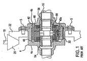
ディセッツによる米国特許第6688194号明細書のディファレンシャルを示す図1〜図3をまず参照すると、従来技術において、環状スリーブ40を介して一直線状に配置される一対の出力軸8及び10を駆動させるために駆動軸18によって回転駆動されるハウジング4と、一対のクラッチ部材46及び48の対向面に含まれ直径方向に配置される一対の溝50(図3)に収容されるクロスピン44と、環状の摩擦パック64及び68と、サイドギヤ54及び56とから構成されるロッキングディファレンシャルを提供することが公知である。各クラッチ部材の隣接面に含まれる対向するボア72に嵌合された圧縮スプリング70は、各クラッチ部材を、摩擦パックが通常の圧縮状態に維持するために互いに離れるように付勢し、それによって、各クラッチ部材46及び48が、通常サイドギヤ54及び56にそれぞれ連結される。各クラッチ部材間の相対的なわずかな角度変位は、各クラッチ部材の隣接面に含まれるオーバサイズの凹部80に対応する突起(図3)によって許容される。 Referring first to FIGS. 1-3 showing the differential of US Pat. No. 6,688,194 to Desets, in the prior art, for driving a pair of
この従来のロッキングディファレンシャルにおいては、一方の出力軸の回転速度が、他方の出力軸よりも所定量オーバランしたとき(例えば、旋回時に発生するように)、各クラッチ部材46及び48は相対的にわずかに角度変位して、クロスピン44が溝50の斜壁部に沿って上昇するとすぐ、オーバランした出力軸に対応する摩擦パックはもう圧縮されず、該オーバランした出力軸は自由状態となる。旋回が終了して各出力軸の回転速度が等しくなったとき、クロスピン44は溝50の駆動面に接触するように位置して、両方の摩擦パックが出力軸8及び10を駆動させるために通常の圧縮状態に戻る。 In this conventional locking differential, when the rotational speed of one output shaft is overrun by a predetermined amount compared to the other output shaft (for example, it occurs during turning), each of the
図4〜図7に示す本発明を次に参照すると、従来技術のディファレンシャルの圧縮スプリングが、摩擦パックアッセンブリ164及び166のそれぞれが直接連携するサイドギヤ周囲で同心上に取り付けられる弾性環状ディスク手段169によって代替される。さらに、詳述すると、改善されたディファレンシャルでは、円筒状のハウジング104は中央チャンバ105(図10)を含み、その長手軸L周りを回転するように配置されている。ハウジングは、出力軸108及び110にそれぞれスプライン結合された一対のサイドギヤ154及び156が回転自在に挿入される一対の対向する開口部107及び109を含む一対の端壁部104aを含む。ハウジングは、またハウジングチャンバを対角線上に横切るように延びるクロスピン144の両端が挿入される直角に配置された一対の開口部143を含む。クロスピンは、サイドギヤ周りに同心上に配置された環状クラッチ部材146及び148の隣接面に含まれる対向した溝150内に延びる。各クラッチ部材間でわずかに制御された相対的な角度変位が、各クラッチ部材の隣接端面に備えられた突起178及びオーバサイズの溝180間の連携によって許容される。 Referring now to the present invention shown in FIGS. 4-7, prior art differential compression springs are provided by resilient annular disk means 169 mounted concentrically around the side gear with which each of the
クラッチ部材146及び148の遠端部は、環状摩擦パック164及び166をそれぞれ収容する座ぐり147を含む。従来から公知であるように、摩擦パックは、サイドギヤ及びクラッチ部材のそれぞれに相対的に軸方向へスライド移動可能で、内周にサイドギヤがスプライン結合された摩擦プレートと、外周にクラッチ部材がスプライン結合された反発プレートとが交互に含まれて構成される。本発明の特徴によれば、摩擦パックは、通常、サイドギヤ周りで同心上に設けた座ぐり147内に配置される環状弾性ディスク手段169によって圧縮状態で維持される。これら弾性ディスク手段は、ハウジング104の対向する端壁部104aとの反作用により、各クラッチ部材を共にクロスピン144の方向に付勢している。図10に示すように、ハウジング端壁部104aは、以下に詳述しているように、弾性ディスク及び摩擦パックの位置を維持するために配置される環状突起104bを備えている。 The distal ends of the
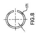
本発明によれば、環状弾性ディスク手段169は、1つまたはそれ以上の波形ワッシャー171(図8及び図9)の配列、または、図11に示すような複数のディスクスプリングすなわち皿ばね(belleview washers)170の配列で構成してもよい。ディスクスプリング170は、摩擦パックの自由端(図12)、摩擦プレートと反発プレートの間(図13)、または図14に示されるように座ぐりの底壁部147aの近接した部位のいずれかに選択的に配置される。同様に、弾性ディスク手段が環状波形スプリングで構成されるとき、それらは、図15、図16及び図17に示されるように対応した態様で配置される。弾性ディスク手段をその場所に保持するために、環状ビード104cを各環状突起部の面の周端部に溶接してもよい。 According to the present invention, the annular elastic disc means 169 comprises an array of one or more corrugated washers 171 (FIGS. 8 and 9) or a plurality of disc springs or belleview washers as shown in FIG. ) It may be composed of 170 arrays. The
作動中、ハウジング104がそれに接続される駆動軸(図示略)によって一定方向に回転されたとき、各出力軸108及び110は、クロスピン144、溝150、クラッチ部材146及び148、圧縮摩擦パック164及び166、及びサイドギヤ146及び148のそれぞれを経由して同一回転速度で駆動される。一方の出力軸が他方の出力軸よりも所定量オーバランしたとき、各クラッチ部材は、溝150の対応する斜壁部に沿って上昇するクロスピン144によって相対的にわずかに角度変位して、それによって、弾性ディスク手段169によって生じる付勢力に抗して各クラッチ部材が離れるように変位する。オーバランした出力軸に対応する摩擦パックは圧縮されない状態となり、するとすぐ、サイドギヤ及びオーバランした出力軸はディファレンシャルとの接続が断たれ自由状態となる。オーバラン状態が終了したとき、各クラッチ部材146及び148は、両方の摩擦パック164及び166の圧縮を生じさせるために互いの方向に再び付勢され、するとすぐ、各出力軸は再び同一回転速度で駆動される。 In operation, when the
本発明の他の特徴によれば、ロッキングディファレンシャルのより有益な動作は、摩擦パックの摩擦プレート及び反発プレートが、硬度Rc44〜Rc47のSAE1074〜1075のバネ鋼で形成されたとき達成されることが判明した。 According to another aspect of the invention, more beneficial operation of the locking differential is achieved when the friction plate friction plate and rebound plate are formed of SAE 1074-1075 spring steel of hardness Rc44-Rc47. found.
また各環状突起104bの面上に溶接された厚さ略0.072インチを有する環状ボス104cを備えることが好ましいことが判明した。ハウジング104の側壁部内に含まれるウィンド開口部111に通じるチャンバ105内の構成部品のアッセンブリは、以前使用されていた圧縮スプリングを本発明の環状弾性ディスク手段に代替したことにより、従来のロッキングディファレンシャルよりも簡素化される。 It has also been found preferable to have an
ハウジング104は、他のディファレンシャルハウジング内に組み込まれるために設計された管状スリーブとして形成できることは明りょうである。 It will be apparent that the
特許法の規定に従って本発明の好ましい形状及び具体例が示され記載されているが、当業者にとって上述した本発明の記載から逸脱することのない変更がなされることは明白である。 While preferred shapes and embodiments of the invention have been shown and described in accordance with the provisions of the patent law, it will be apparent to those skilled in the art that changes can be made without departing from the above description of the invention.
Claims (9)
Translated fromJapanese(a)略円筒状のハウジング(104)は、駆動軸によって長手軸周りに回転駆動されることに適し、該ハウジングは中央チャンバ(105)と、前記長手軸に沿って一直線上に配置され前記チャンバに連通する一対の第1開口部(107)を含む一対の対向する第1端壁部(104a)とを含み、
(b)クロスピン(144)は、前記長手軸に垂直で前記チャンバを横切るように直径方向に延び、該クロスピンは、前記ハウジングの一対の対向する第2壁部にそれぞれ含まれる一対の一直線上に配置された第2開口部(143)に嵌合される一対の端部を有し、
(c)一対の管状のサイドギヤ(154;156)は、前記クロスピンと反対側の前記第1ハウジング開口部に回転自在にそれぞれ嵌合され、前記サイドギヤの内側が出力軸の近接した端部に互いに回転不能でそれぞれスプライン結合され、
(d)同軸上で軸方向に間隔をあけて配置された一対の環状クラッチ部材(146;148)は、前記クロスピンと反対側で前記サイドギヤ周りに同心上にそれぞれ配置され、前記各クラッチ部材の遠端部は座ぐり(147;149)をそれぞれ含み、前記各クラッチ部材の隣接面には、前記クロスピンを収容する対向して直径方向に延びるカム溝(150)を含み、前記各クラッチ部材は、該クラッチ部材の相対的な角度変位を制限するように係合されるロッキング手段(178、180)を含み、
(e)一対の環状摩擦パック手段(164、166)は、前記サイドギヤ周りに同心上の前記座ぐり内にそれぞれ配置され、各前記摩擦パック手段は、複数の環状の摩擦及び反発プレートを交互に含み、前記摩擦プレートは、その内側が対応するサイドギヤの外側スプラインに対して互いに回転不能で軸移動可能にスプライン結合され、前記反発プレートは、その外側が対応するクラッチ部材の座ぐり面に含まれる内側スプラインに対して互いに回転不能で軸移動可能にスプライン結合され、各前記摩擦パック手段は、前記摩擦及び反発プレートが互いに相対的に自由回転となる非圧縮状態と、前記摩擦及び反発プレートの対向面が互いに回転不能に接触して、それによりクラッチ部材の回転を対応するサイドギヤに連結する軸方向圧縮状態との間で作動可能であり、
(f)スプリング手段は、通常前記摩擦パック手段を圧縮状態の方向へ付勢して、前記スプリング手段は、前記サイドギヤ周りに同心上に設けられた座ぐり内に配置される弾性環状ディスク手段(170;171)を含み、
(g)前記クラッチ部材のカム溝は、一方の出力軸の回転速度が他方の出力軸の回転速度よりも所定量オーバランしたとき、オーバランしたサイドギヤ及びクラッチ部材が前記クロスピンと相対的に角度変位するような形状を有し、その結果、オーバランした摩擦パックは通常の圧縮状態から非圧縮状態に作動され、オーバランした出力軸は、自由な非接続状態となる、
ことを特徴とするロッキングディファレンシャル。In a vehicle locking differential having a drive shaft and a pair of collinearly arranged output shafts,
(A) The substantially cylindrical housing (104) is suitable for being driven to rotate about a longitudinal axis by a drive shaft, the housing being arranged in a straight line along the longitudinal axis with the central chamber (105). A pair of opposing first end walls (104a) including a pair of first openings (107) communicating with the chamber;
(B) The cross pin (144) extends in a diametrical direction perpendicular to the longitudinal axis and across the chamber, and the cross pin is on a pair of straight lines respectively included in a pair of opposing second wall portions of the housing. Having a pair of ends fitted into the second opening (143) disposed;
(C) A pair of tubular side gears (154; 156) are rotatably fitted in the first housing openings on the opposite side of the cross pins, respectively, and the inner sides of the side gears are connected to the adjacent ends of the output shaft. Non-rotatable and splined,
(D) A pair of annular clutch members (146; 148) arranged coaxially and spaced apart in the axial direction are arranged concentrically around the side gear on the side opposite to the cross pin, and The distal ends include counterbore (147; 149), respectively, and adjacent surfaces of each clutch member include opposing diametrically extending cam grooves (150) that house the cross pins, wherein each clutch member includes Locking means (178, 180) engaged to limit relative angular displacement of the clutch member;
(E) A pair of annular friction pack means (164, 166) are respectively disposed in the counterbore concentrically around the side gear, each friction pack means alternating a plurality of annular friction and repulsion plates And the friction plate is splined so that the inner side thereof is non-rotatable and axially movable with respect to the outer side spline of the corresponding side gear, and the repulsion plate is included on the counterbore surface of the corresponding clutch member. Each friction pack means is in a non-compressed state in which the friction and repulsion plates are free to rotate relative to each other, and the friction and repulsion plates are opposed to each other. Axial compression state where the surfaces contact each other in a non-rotatable manner thereby coupling the rotation of the clutch member to the corresponding side gear It is operable between,
(F) The spring means normally biases the friction pack means in the direction of the compression state, and the spring means is an elastic annular disk means (not shown) disposed in a counterbore provided concentrically around the side gear. 170; 171),
(G) In the cam groove of the clutch member, when the rotational speed of one output shaft overruns by a predetermined amount from the rotational speed of the other output shaft, the overrun side gear and clutch member are angularly displaced relative to the cross pin. As a result, the overrun friction pack is operated from the normal compression state to the non-compression state, and the overrun output shaft is freely disconnected.
A locking differential.
Applications Claiming Priority (3)
| Application Number | Priority Date | Filing Date | Title |
|---|---|---|---|
| US11/705,901US7874954B2 (en) | 2007-02-14 | 2007-02-14 | Locking differential including resilient disc means |
| US11/705,901 | 2007-02-14 | ||
| PCT/IB2008/000316WO2008099264A1 (en) | 2007-02-14 | 2008-02-13 | Improved locking differential including resilient disc means |
Publications (2)
| Publication Number | Publication Date |
|---|---|
| JP2010518343Atrue JP2010518343A (en) | 2010-05-27 |
| JP5257792B2 JP5257792B2 (en) | 2013-08-07 |
Family
ID=39485155
Family Applications (1)
| Application Number | Title | Priority Date | Filing Date |
|---|---|---|---|
| JP2009549862AExpired - Fee RelatedJP5257792B2 (en) | 2007-02-14 | 2008-02-13 | Improved locking differential including elastic disk means |
Country Status (15)
| Country | Link |
|---|---|
| US (1) | US7874954B2 (en) |
| EP (1) | EP2126413B1 (en) |
| JP (1) | JP5257792B2 (en) |
| KR (1) | KR101648586B1 (en) |
| CN (1) | CN101611244B (en) |
| AT (1) | ATE503137T1 (en) |
| AU (1) | AU2008215903B2 (en) |
| BR (1) | BRPI0807266A2 (en) |
| CA (1) | CA2678086A1 (en) |
| DE (1) | DE602008005721D1 (en) |
| ES (1) | ES2361084T3 (en) |
| MX (1) | MX2009008715A (en) |
| PL (1) | PL2126413T3 (en) |
| TW (1) | TWI424127B (en) |
| WO (1) | WO2008099264A1 (en) |
Families Citing this family (14)
| Publication number | Priority date | Publication date | Assignee | Title |
|---|---|---|---|---|
| CN101907158A (en)* | 2009-06-04 | 2010-12-08 | 左臣伟 | Differential system with transcendent function |
| US8146458B2 (en)* | 2009-07-27 | 2012-04-03 | Eaton Corporation | Locking differential having improved torque capacity |
| US8231493B2 (en)* | 2009-07-27 | 2012-07-31 | Eaton Corporation | Differential having improved torque capacity and torque density |
| US20110021305A1 (en)* | 2009-07-27 | 2011-01-27 | Radzevich Stephen P | Differential having self-adjusting gearing |
| CN102094957B (en)* | 2011-03-02 | 2012-12-26 | 江铃控股有限公司 | Automobile locking type differential |
| US8857589B2 (en) | 2011-11-29 | 2014-10-14 | The Hilliard Corporation | Friction disk mechanism for bi-directional overrunning clutch |
| KR20150050529A (en) | 2012-08-29 | 2015-05-08 | 이턴 코포레이션 | Locking differential having combination preload springs for maintained contact |
| EP2847495A2 (en) | 2012-08-29 | 2015-03-18 | Eaton Corporation | Locking differential having dampening communication spring |
| US9303748B2 (en) | 2012-11-19 | 2016-04-05 | Eaton Corporation | Collapsible clutching differential |
| JP2015535578A (en) | 2012-11-28 | 2015-12-14 | イートン コーポレーションEaton Corporation | Differential locking device with spring-loaded pad for preload |
| US9334941B2 (en) | 2013-03-14 | 2016-05-10 | Eaton Corporation | Inboard spring arrangement for a clutch actuated differential |
| EP2778477A3 (en) | 2013-03-14 | 2017-04-26 | Eaton Corporation | Inboard spring arrangement for a clutch actuated differential |
| CN104074947B (en)* | 2013-03-28 | 2016-09-07 | 比亚迪股份有限公司 | A kind of active differential mechanism, the control system with this mechanism and vehicle |
| CA2887514C (en) | 2014-04-09 | 2023-05-23 | TAP Worldwide, LLC | Locking differential |
Citations (5)
| Publication number | Priority date | Publication date | Assignee | Title |
|---|---|---|---|---|
| JPS6117533U (en)* | 1984-07-06 | 1986-02-01 | 栃木富士産業株式会社 | cam device |
| JPH0771563A (en)* | 1993-06-30 | 1995-03-17 | Tochigi Fuji Ind Co Ltd | Differential gear |
| JP2003138217A (en)* | 2001-11-01 | 2003-05-14 | Stt Kk | Rustproof lubricating coating composition |
| JP2006519956A (en)* | 2003-03-07 | 2006-08-31 | テック ディベロップメント,インク. | Inertia drive torque transmission level control and engine starter incorporating it |
| JP2007032835A (en)* | 2005-07-26 | 2007-02-08 | Tractech Inc | Enhanced gearless lock differential |
Family Cites Families (13)
| Publication number | Priority date | Publication date | Assignee | Title |
|---|---|---|---|---|
| US4513633A (en)* | 1982-04-08 | 1985-04-30 | Eaton Corporation | Positive drive and generated cam surfaces therefor |
| US4640143A (en)* | 1982-04-22 | 1987-02-03 | Schou Carl Einar | Self-locking differential with hexagonal drive rod |
| US4498355A (en)* | 1982-04-22 | 1985-02-12 | Schou Carl Einar | Self locking differential |
| JPS60240526A (en)* | 1984-05-16 | 1985-11-29 | Tochigi Fuji Ind Co Ltd | Power transmission system |
| JPH0635548B2 (en)* | 1984-07-04 | 1994-05-11 | 三菱化成株式会社 | Anthraquinone dye and liquid crystal composition containing the dye |
| US4735108A (en)* | 1985-11-21 | 1988-04-05 | Tochigifujisangyo Kabushikigaisha | Power transmission device |
| US4845831A (en)* | 1985-12-13 | 1989-07-11 | Schou Carl Einar | Open casing, self-locking differential |
| US5413015A (en)* | 1993-06-28 | 1995-05-09 | Zentmyer; John | Automotive vehicle differential assembly |
| US5751733A (en)* | 1996-09-16 | 1998-05-12 | Cirrus Logic, Inc. | Interleaved redundancy sector for correcting an unrecoverable sector in a disc storage device |
| US5727430A (en)* | 1996-10-24 | 1998-03-17 | Dyneer Corporation | Locking differential including friction pack clutch means |
| US5715733A (en) | 1996-11-25 | 1998-02-10 | Tractech Inc. | Locking differential including a spring cap biasing assembly |
| US6688194B2 (en)* | 2001-10-04 | 2004-02-10 | Tractech Inc. | Locking differential including improved clutch member and adapter sleeve |
| US6705813B2 (en)* | 2002-02-07 | 2004-03-16 | Pierre P. Schwab | Snap disc device |
- 2007
- 2007-02-14USUS11/705,901patent/US7874954B2/enactiveActive
- 2008
- 2008-02-13CACA002678086Apatent/CA2678086A1/ennot_activeAbandoned
- 2008-02-13WOPCT/IB2008/000316patent/WO2008099264A1/enactiveApplication Filing
- 2008-02-13PLPL08709802Tpatent/PL2126413T3/enunknown
- 2008-02-13EPEP08709802Apatent/EP2126413B1/ennot_activeNot-in-force
- 2008-02-13TWTW097104959Apatent/TWI424127B/ennot_activeIP Right Cessation
- 2008-02-13ATAT08709802Tpatent/ATE503137T1/enactive
- 2008-02-13MXMX2009008715Apatent/MX2009008715A/enactiveIP Right Grant
- 2008-02-13KRKR1020097019059Apatent/KR101648586B1/ennot_activeExpired - Fee Related
- 2008-02-13JPJP2009549862Apatent/JP5257792B2/ennot_activeExpired - Fee Related
- 2008-02-13CNCN2008800051364Apatent/CN101611244B/ennot_activeExpired - Fee Related
- 2008-02-13ESES08709802Tpatent/ES2361084T3/enactiveActive
- 2008-02-13AUAU2008215903Apatent/AU2008215903B2/ennot_activeCeased
- 2008-02-13BRBRPI0807266-3Apatent/BRPI0807266A2/ennot_activeApplication Discontinuation
- 2008-02-13DEDE602008005721Tpatent/DE602008005721D1/enactiveActive
Patent Citations (5)
| Publication number | Priority date | Publication date | Assignee | Title |
|---|---|---|---|---|
| JPS6117533U (en)* | 1984-07-06 | 1986-02-01 | 栃木富士産業株式会社 | cam device |
| JPH0771563A (en)* | 1993-06-30 | 1995-03-17 | Tochigi Fuji Ind Co Ltd | Differential gear |
| JP2003138217A (en)* | 2001-11-01 | 2003-05-14 | Stt Kk | Rustproof lubricating coating composition |
| JP2006519956A (en)* | 2003-03-07 | 2006-08-31 | テック ディベロップメント,インク. | Inertia drive torque transmission level control and engine starter incorporating it |
| JP2007032835A (en)* | 2005-07-26 | 2007-02-08 | Tractech Inc | Enhanced gearless lock differential |
Also Published As
| Publication number | Publication date |
|---|---|
| ATE503137T1 (en) | 2011-04-15 |
| AU2008215903A1 (en) | 2008-08-21 |
| EP2126413A1 (en) | 2009-12-02 |
| TWI424127B (en) | 2014-01-21 |
| PL2126413T3 (en) | 2011-08-31 |
| KR101648586B1 (en) | 2016-08-16 |
| JP5257792B2 (en) | 2013-08-07 |
| DE602008005721D1 (en) | 2011-05-05 |
| AU2008215903B2 (en) | 2012-07-05 |
| MX2009008715A (en) | 2009-10-26 |
| CN101611244A (en) | 2009-12-23 |
| CN101611244B (en) | 2013-06-12 |
| TW200842268A (en) | 2008-11-01 |
| US20080190240A1 (en) | 2008-08-14 |
| BRPI0807266A2 (en) | 2014-05-06 |
| US7874954B2 (en) | 2011-01-25 |
| ES2361084T3 (en) | 2011-06-13 |
| KR20090110382A (en) | 2009-10-21 |
| EP2126413B1 (en) | 2011-03-23 |
| WO2008099264A1 (en) | 2008-08-21 |
| CA2678086A1 (en) | 2008-08-21 |
Similar Documents
| Publication | Publication Date | Title |
|---|---|---|
| JP5257792B2 (en) | Improved locking differential including elastic disk means | |
| JPWO2017154870A1 (en) | Torque transmission joint and electric power steering device | |
| US5741199A (en) | Limited slip differential recessed spring design | |
| JP6117991B2 (en) | Toroidal continuously variable transmission | |
| JP4905036B2 (en) | Driving force transmission device | |
| CN115667764B (en) | Differential device | |
| JP4998081B2 (en) | Conical friction ring type continuously variable transmission | |
| JP2024115861A (en) | Limited slip differential | |
| JP2008248937A (en) | Driving force transmission device | |
| JPS6335850B2 (en) | ||
| JP2024013596A (en) | Electric friction clutch device | |
| JP4725768B2 (en) | Toroidal continuously variable transmission | |
| JP2025082451A (en) | Differential limiting device | |
| JP3458490B2 (en) | Toroidal type continuously variable transmission | |
| JP4378671B2 (en) | Toroidal continuously variable transmission | |
| JP2535385Y2 (en) | Differential limiter | |
| JP4839553B2 (en) | Friction roller transmission and friction roller transmission with motor | |
| JP2025005350A (en) | Clutch device | |
| JP2005214373A (en) | Toroidal continuously variable transmission | |
| JP2023159566A (en) | Pressing mechanism of clutch | |
| JP3874903B2 (en) | Differential device | |
| WO2023195203A1 (en) | Reverse-input blocking clutch | |
| JPH09291981A (en) | Bevel gear assembly and differential device having bevel gear assembly used in differential gear mechanism | |
| JP2005320992A (en) | Toroidal continuously variable transmission assembly method and assembly jig | |
| JPH11173404A (en) | Differential limiting device |
Legal Events
| Date | Code | Title | Description |
|---|---|---|---|
| A621 | Written request for application examination | Free format text:JAPANESE INTERMEDIATE CODE: A621 Effective date:20101118 | |
| A977 | Report on retrieval | Free format text:JAPANESE INTERMEDIATE CODE: A971007 Effective date:20121011 | |
| A131 | Notification of reasons for refusal | Free format text:JAPANESE INTERMEDIATE CODE: A131 Effective date:20121017 | |
| A601 | Written request for extension of time | Free format text:JAPANESE INTERMEDIATE CODE: A601 Effective date:20130116 | |
| A602 | Written permission of extension of time | Free format text:JAPANESE INTERMEDIATE CODE: A602 Effective date:20130123 | |
| A521 | Request for written amendment filed | Free format text:JAPANESE INTERMEDIATE CODE: A523 Effective date:20130213 | |
| TRDD | Decision of grant or rejection written | ||
| A01 | Written decision to grant a patent or to grant a registration (utility model) | Free format text:JAPANESE INTERMEDIATE CODE: A01 Effective date:20130313 | |
| A61 | First payment of annual fees (during grant procedure) | Free format text:JAPANESE INTERMEDIATE CODE: A61 Effective date:20130411 | |
| FPAY | Renewal fee payment (event date is renewal date of database) | Free format text:PAYMENT UNTIL: 20160502 Year of fee payment:3 | |
| R150 | Certificate of patent or registration of utility model | Ref document number:5257792 Country of ref document:JP Free format text:JAPANESE INTERMEDIATE CODE: R150 Free format text:JAPANESE INTERMEDIATE CODE: R150 | |
| R250 | Receipt of annual fees | Free format text:JAPANESE INTERMEDIATE CODE: R250 | |
| R250 | Receipt of annual fees | Free format text:JAPANESE INTERMEDIATE CODE: R250 | |
| R250 | Receipt of annual fees | Free format text:JAPANESE INTERMEDIATE CODE: R250 | |
| LAPS | Cancellation because of no payment of annual fees |