JP2010517733A - Apparatus and method for projecting subcutaneous structure onto object surface - Google Patents
Apparatus and method for projecting subcutaneous structure onto object surfaceDownload PDFInfo
- Publication number
- JP2010517733A JP2010517733AJP2009550140AJP2009550140AJP2010517733AJP 2010517733 AJP2010517733 AJP 2010517733AJP 2009550140 AJP2009550140 AJP 2009550140AJP 2009550140 AJP2009550140 AJP 2009550140AJP 2010517733 AJP2010517733 AJP 2010517733A
- Authority
- JP
- Japan
- Prior art keywords
- image
- value
- pixel
- contrast
- input image
- Prior art date
- Legal status (The legal status is an assumption and is not a legal conclusion. Google has not performed a legal analysis and makes no representation as to the accuracy of the status listed.)
- Pending
Links
Images


Classifications
- G—PHYSICS
- G02—OPTICS
- G02B—OPTICAL ELEMENTS, SYSTEMS OR APPARATUS
- G02B21/00—Microscopes
- G02B21/36—Microscopes arranged for photographic purposes or projection purposes or digital imaging or video purposes including associated control and data processing arrangements
- A—HUMAN NECESSITIES
- A61—MEDICAL OR VETERINARY SCIENCE; HYGIENE
- A61B—DIAGNOSIS; SURGERY; IDENTIFICATION
- A61B5/00—Measuring for diagnostic purposes; Identification of persons
- A61B5/0059—Measuring for diagnostic purposes; Identification of persons using light, e.g. diagnosis by transillumination, diascopy, fluorescence
- A—HUMAN NECESSITIES
- A61—MEDICAL OR VETERINARY SCIENCE; HYGIENE
- A61B—DIAGNOSIS; SURGERY; IDENTIFICATION
- A61B5/00—Measuring for diagnostic purposes; Identification of persons
- A61B5/48—Other medical applications
- A61B5/4887—Locating particular structures in or on the body
- A61B5/489—Blood vessels
- G—PHYSICS
- G02—OPTICS
- G02B—OPTICAL ELEMENTS, SYSTEMS OR APPARATUS
- G02B23/00—Telescopes, e.g. binoculars; Periscopes; Instruments for viewing the inside of hollow bodies; Viewfinders; Optical aiming or sighting devices
- G02B23/24—Instruments or systems for viewing the inside of hollow bodies, e.g. fibrescopes
- G—PHYSICS
- G06—COMPUTING OR CALCULATING; COUNTING
- G06T—IMAGE DATA PROCESSING OR GENERATION, IN GENERAL
- G06T5/00—Image enhancement or restoration
- G06T5/73—Deblurring; Sharpening
- G06T5/75—Unsharp masking
- A—HUMAN NECESSITIES
- A61—MEDICAL OR VETERINARY SCIENCE; HYGIENE
- A61B—DIAGNOSIS; SURGERY; IDENTIFICATION
- A61B5/00—Measuring for diagnostic purposes; Identification of persons
- A61B5/44—Detecting, measuring or recording for evaluating the integumentary system, e.g. skin, hair or nails
- A61B5/441—Skin evaluation, e.g. for skin disorder diagnosis
Landscapes
- Health & Medical Sciences (AREA)
- Life Sciences & Earth Sciences (AREA)
- Physics & Mathematics (AREA)
- Engineering & Computer Science (AREA)
- Animal Behavior & Ethology (AREA)
- Veterinary Medicine (AREA)
- Biophysics (AREA)
- Biomedical Technology (AREA)
- Heart & Thoracic Surgery (AREA)
- Medical Informatics (AREA)
- Molecular Biology (AREA)
- Surgery (AREA)
- General Physics & Mathematics (AREA)
- General Health & Medical Sciences (AREA)
- Public Health (AREA)
- Pathology (AREA)
- Vascular Medicine (AREA)
- Optics & Photonics (AREA)
- Theoretical Computer Science (AREA)
- Astronomy & Astrophysics (AREA)
- Multimedia (AREA)
- Chemical & Material Sciences (AREA)
- Analytical Chemistry (AREA)
- Investigating Or Analysing Materials By Optical Means (AREA)
- Studio Devices (AREA)
- Measurement Of The Respiration, Hearing Ability, Form, And Blood Characteristics Of Living Organisms (AREA)
- Closed-Circuit Television Systems (AREA)
Abstract
Translated fromJapaneseDescription
Translated fromJapanese本発明は赤外線拡散に係り、具体的には赤外線を拡散させて物体に照らして反射された赤外線を基盤にして物体表面下に埋め立てされた構造物のビデオ画像を作った次に、この画像を物体表面に投射する装置に関する。 The present invention relates to infrared diffusion, in particular, creating a video image of a structure buried beneath the object surface based on the infrared light reflected and diffused against the object. The present invention relates to an apparatus for projecting onto an object surface.
医学的治療過程で患者の身体である腕と脚で血管を捜し出さなければならない場合が多い。血管を探すことは難しい事であって、血管が小さかったり相当量の皮下脂肪やその他組織下にある時は特にむずかしい。このような血管を探すのに助けを与えるように設計された既存の撮影装置はその性能がよくなかった。 During medical treatment, it is often necessary to search for blood vessels with the arms and legs of the patient's body. Finding blood vessels is difficult, especially when the blood vessels are small or under a significant amount of subcutaneous fat or other tissue. Existing imaging devices designed to help find such blood vessels have had poor performance.
Contrast Enhancing Illuminatorという名称の米国特許5,969,754に開示された装置は皮下血管を見るためのものである。この装置では標的身体部分に赤外線を拡散して投射して生じた反射光を利用して皮下血管画像を作って、この画像を身体部分に再び投射するが、その内容を本発明で参考にした。 The device disclosed in US Pat. No. 5,969,754, named Contrast Enhancing Illuminator, is for viewing subcutaneous blood vessels. In this device, a subcutaneous blood vessel image is created using reflected light generated by diffusing and projecting infrared rays to the target body part, and this image is projected again on the body part. The contents are referred to in the present invention. .
標的に画像を投射し返す前に映像が改善されるが、このような改善技術は場合によって違うものが良い。また、画像を標的身体部分に投射し返す時、皮膚のトーンや組織、毛の量のような要素によって画像の画質が悪くなったりする。したがって、上の特許の装置と方法は改善が必要である。 The video is improved before the image is projected back to the target, but such improvement techniques may be different in some cases. Also, when the image is projected back onto the target body part, the image quality may be degraded due to factors such as skin tone, tissue and hair volume. Thus, the apparatus and method of the above patent needs improvement.
Diffuse Infrared Light Imaging systemという名称の米国特許6,556,858とImaging System Using Diffuse Infrared Lightという名称の米国特許7,239,909の内容も本発明で参考にしたことであって、米国特許5,969,754の装置と方法を改善したものであるが、相変らず皮下血管と周辺組織間の視覚的コントラストを改善する必要がある。 The contents of US Patent No. 6,556,858 named Diffuse Infrared Light Imaging System and US Patent No. 7,239,909 named Imaging System Using Diffuse Light were also referred to in the present invention. Although the devices and methods of 969 and 754 are improved, there is still a need to improve the visual contrast between the subcutaneous blood vessels and surrounding tissues.
本発明の目的は皮下構造物と周辺組織間のコントラストを改善する装置と方法を提供して既存のこのような問題点を克服することにある。 It is an object of the present invention to provide an apparatus and method for improving the contrast between a subcutaneous structure and surrounding tissue to overcome such existing problems.
本発明の装置と方法によれば、赤外線を体組織に照らして皮下血管の鮮明度を改善して、反射赤外線を基盤にして体組織と皮下血管の画像を作る。この装置は赤外線を出す赤外線照明源と、体組織で反射された赤外線を受けて改善した体組織画像を作る撮影機を含む。改善した画像はアンシャープマスクの適用に関するコントラスト強調技術で生成される。この装置は撮影された体組織に改善画像を投射して撮影機から出力信号を受けるプロジェクターをさらに含む。 According to the apparatus and method of the present invention, the sharpness of the subcutaneous blood vessels is improved by irradiating the body tissues with infrared rays, and images of the body tissues and subcutaneous blood vessels are created based on the reflected infrared rays. The apparatus includes an infrared illumination source that emits infrared light and a photographing machine that receives the infrared light reflected by the body tissue to produce an improved body tissue image. The improved image is generated with a contrast enhancement technique for application of an unsharp mask. The apparatus further includes a projector that projects an improved image onto the imaged body tissue and receives an output signal from the camera.
本発明の他の特徴によるコントラスト強調技術によれば解像度が相異なる第1及び第2ぼかしフィルターを利用する。このような第1及び第2ぼかしフィルターを利用する時、入力画像のそれぞれの画素に平均窓を適用する。 The contrast enhancement technique according to another aspect of the present invention uses first and second blur filters having different resolutions. When using such first and second blur filters, an average window is applied to each pixel of the input image.
また、コントラストを強調する時ぼかしフィルターを調整してアンシャープマスクを作ったり、画素の値が臨界値より小さい時は画素の値が所定の値に変わるように画素データに臨界値を設定したり、それぞれの画素の値を設定量ぐらい違いが生じるようにして補正された画素値を生成して全ての補正された画素値が所定範囲を外れるとこの値を所定範囲内の値に適用したり、コントラストを強調する時線形縮尺を適用したりする。 Also, when enhancing the contrast, the blur filter is adjusted to create an unsharp mask, or when the pixel value is smaller than the critical value, the critical value is set in the pixel data so that the pixel value changes to a predetermined value. When a corrected pixel value is generated so that the value of each pixel differs by a set amount, and all corrected pixel values are out of a predetermined range, this value is applied to a value within the predetermined range. Apply a linear scale when emphasizing contrast.
また、入力画像が画素データで構成されて、コントラストを強調する時それぞれの画素値の絶対値を処理段階毎に用いるか、最大フィルター窓を用いて標的画素の値を最大フィルターウインドウ内部の最大画素値で設定する。 Also, when the input image is composed of pixel data and the contrast is enhanced, the absolute value of each pixel value is used for each processing stage, or the target pixel value is set to the maximum pixel inside the maximum filter window using the maximum filter window. Set by value.
また、撮影機に2種類以上のコントラスト強調オプションとセレクターが付いていて、使用者がセレクターを用いてコントラスト強調オプションを選択して改善した画像を生成する。 Also, the photographing machine has two or more types of contrast enhancement options and a selector, and the user selects the contrast enhancement option using the selector and generates an improved image.
また、体組織部分が血管構造を有する体組織部分であって、使用者がこのような血管構造を探すのに助けになるデータが改善した画像に入っていることもできる。したがって、皮下血管を探したり、避けることに関連した過程を本発明の装置と方法を利用して実行することができる。 In addition, the body tissue part may be a body tissue part having a vascular structure, and data for helping a user to search for such a vascular structure may be included in an improved image. Thus, processes related to searching for or avoiding subcutaneous blood vessels can be performed using the apparatus and method of the present invention.
技術的観点で、本発明は患者の腕と脚のような身体内部の血管を探す状況に利用される。従来の技術では、このような血管を探すことは困難だったが、分厚い皮下脂肪下にある血管は特に探すのが難しかった。このような血管を探すのに用いられる既存の撮影装置の性能は満足できるものではなかった。したがって、本発明の技術的問題は皮下血管と周辺組織間の視覚的コントラストを強調する装置と方法を提供することにある。 From a technical point of view, the present invention is used in situations where it looks for blood vessels inside the body, such as a patient's arms and legs. In the prior art, it was difficult to find such blood vessels, but it was particularly difficult to find blood vessels under thick subcutaneous fat. The performance of existing imaging devices used to search for such blood vessels has not been satisfactory. Accordingly, the technical problem of the present invention is to provide an apparatus and method that enhances the visual contrast between subcutaneous blood vessels and surrounding tissue.
この問題は物体表面下に埋め立てされた構造物の鮮明度を改善する装置で解決される。医療機器は物体で反射された拡散光を受けて入力画像を作って、ここから改善した画像を作るための撮影機と、物体表面に埋立構造物の可視光画像を投射し返すプロジェクターを含む。 This problem is solved with an apparatus that improves the definition of structures buried under the object surface. The medical device includes an imaging device for receiving an diffused light reflected from an object to create an input image, and creating an improved image therefrom, and a projector for projecting a visible light image of the buried structure back on the object surface.
本発明の技術思想は埋立構造物の縁と周辺組織のコントラストをさらに強調して埋立構造物を容易に探す新しいコントラスト強調技術である。その結果、患者の腕と脚で血管を探すことがはるかに容易になる。 The technical idea of the present invention is a new contrast enhancement technique for easily searching for a buried structure by further enhancing the contrast between the edge of the buried structure and the surrounding tissue. As a result, it is much easier to find blood vessels in the patient's arms and legs.
好適には、この装置は体組織で反射されて撮影機により撮影される赤外線を体組織に照らす赤外線光源を具備する。 Preferably, the apparatus includes an infrared light source that illuminates the body tissue with infrared light reflected by the body tissue and photographed by the camera.
本発明のコントラスト強調はアンシャープマスキング作業以外にも入力画像のそれぞれの画素値に一定値を加えて行われるが、この時それぞれの画素値の絶対値を取ったり所定の臨界値を利用する。 The contrast enhancement according to the present invention is performed by adding a constant value to each pixel value of the input image in addition to the unsharp masking operation. At this time, an absolute value of each pixel value is obtained or a predetermined critical value is used.
このように構成された本発明によれば、皮下血管と周辺体組織間のコントラストが著しく改善されて、皮下血管の画像が従来に比べてはるかに鮮明になる。 According to the present invention configured as described above, the contrast between the subcutaneous blood vessel and the surrounding body tissue is remarkably improved, and the image of the subcutaneous blood vessel becomes much clearer than before.
皮膚や体組織は700〜900nm程度の近赤外線は反射するが血液はこの範囲の赤外線を吸収する。したがって、赤外線照明下で採取した体組織のビデオ画像で、血管は暗い線で表され周辺背景はさらに明るく見える。しかし、皮下脂肪の反射性のため、一方向に向かう直射光では皮下脂肪下にある血管を見るのが困難あるいは不可能である。 Skin and body tissues reflect near infrared rays of about 700 to 900 nm, but blood absorbs infrared rays in this range. Therefore, in a video image of body tissue taken under infrared illumination, blood vessels are represented by dark lines and the surrounding background appears brighter. However, because of the reflectivity of subcutaneous fat, it is difficult or impossible to see blood vessels under the subcutaneous fat with direct light directed in one direction.
相当な皮下脂肪がある体組織部分を高拡散赤外線などで照明しながら近赤外線で撮影すると血管と周辺組織間に赤外線直射光で見た時よりはるかに大きいコントラスト(contrast)があることが分かる。皮下脂肪で反射された大部分の拡散赤外線が照準方向から離れるようになるので、高拡散赤外線を組織に照らす時血管と周辺組織間に希望する視覚的コントラストが維持される。 It can be seen that when a body tissue portion having a considerable amount of subcutaneous fat is illuminated with near-infrared rays while illuminating it with high-diffusing infrared rays or the like, there is a much greater contrast between the blood vessels and surrounding tissues than when viewed with infrared direct light. Since most of the diffuse infrared light reflected by the subcutaneous fat moves away from the aiming direction, the desired visual contrast between the blood vessel and the surrounding tissue is maintained when the highly diffuse infrared light is illuminated onto the tissue.
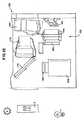
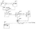
図1は、体組織のような物体32に高拡散赤外線を照らして反射された赤外線を基盤にして物体のビデオ画像を作るための撮影装置2の概略図である。前述したように、物体32が体組織であれば、体組織内皮下脂肪下にある血管がビデオ画像で鮮明に見られる。 FIG. 1 is a schematic view of a photographing
撮影装置2の照明器10は多くの方向で赤外線を物体32に照らす。照明器10は複数個の照明源10a〜fを含むが、照明源毎にそれぞれ他の方向に赤外線を物体32に照らす。図1に示したように、赤外線の方向は物体32表面に対して垂直から大体平行した方向まで多様だ。ここで、このように広範囲な多くの方向で物体32に赤外線を照らすので、赤外線が大きく拡散する。 The
後ほど詳細に説明するが、照明源10a〜fはそれぞれ物体32に向かって一筋ずつ光を照らすための反射面が好ましい。一方、これら照明源はそれぞれ光源であるか、光源と反射面の組合であることができる。 As will be described in detail later, each of the
撮影装置2は物体32を見るための撮影機でビデオカメラ38を利用するが、本明細書で撮影機はカメラを含む概念である。カメラ38は図1の矢印方向に物体32を見ながら、物体で反射された拡散赤外線を受けて反射赤外線を基盤にして物体の電子式ビデオ画像を作る。 The photographing
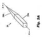
図2は、照明器10の斜視図であって、図3は図2のA−A線断面図で、照明器10に照明源12がある。図3のように、照明源12のランプ26とケース16の誘導孔18間にコールドミラー(34:cold mirror)がある。コールドミラー34は700〜1,100nm程度の赤外線波長帯を外れた全ての光を反射する。誘導孔18に向かってコールドミラー34についていることは赤外線透過フィルター36で、上の赤外線波長帯を外れた光は減衰させて上の赤外線波長帯の光は透過させる。したがって、上の赤外線波長帯の光だけコールドミラー34とフィルター36を過ぎてケース16に到達する。 2 is a perspective view of the
照明源12で赤外線を作ることができる他の方法もある。例えば、LEDで照明源12をすれば良いが、本発明はこれに限定されない。 There are other ways in which the
図4のように、物体32で反射された拡散光を基盤にして物体のビデオ画像を作るのにビデオカメラ38とレンズ40を共に利用する。このビデオカメラ38ではCohuでモデル番号631520010000で製作したCCDビデオカメラが好ましい。レンズ40ではAngenieuxで製作した25mmf−0.95ムービーカメラレンズが好ましい。 As shown in FIG. 4, both the
カメラ38とレンズ40は内部反射部24の管型区間24a内に配置される。図3のように、管型区間24aの開放端部に形成された穴に向かってカメラ38とレンズ40を狙う。このようにすれば、中が空いた導光部22の中心がカメラ38の視野範囲内に位置する。したがって、カメラ38は物体32で反射されて導光部22を過ぎて区間24aの開放端部に入った光を受ける。 The
図4に示したように、管型区間24aの開放端部に赤外線フィルター42を配置する。このフィルター42は物体32で反射された光と、ケース16に入った全ての他の光を受けて700〜1100nm波長帯外の全ての光は濾過する。したがって、フィルター42を介してレンズ40に入る光は選択された波長帯の赤外線であって、これによりカメラ38は照明器10から出て物体32で反射された赤外線を主に受ける。 As shown in FIG. 4, an
物体32の反射光に基づいてカメラ38はビデオ信号形態の物体のビデオ画像を作る。図5のように、ビデオ信号は画質改善ボード44に送られるが、DigiVisionで製作するモデルナンバーICE3000が画質改善ボードで好ましい。画質改善ボード44はカメラ38のビデオ信号を根拠にして改善したビデオ画像信号を生成して、この信号はビデオキャプチャー/ディスプレイボード46に送られるが、例えばMiroで製作したモデル番号20−TDがある。このボード46はデジタル保存器にデジタルフォーマットで保存される画像信号で停止画像をキャプチャーして、またビデオモニター48に実施間ディスプレイするようにビデオ画像信号をフォーマットしたりする。 Based on the reflected light of the
照明器10は赤外線を拡散させる他の手段を利用することもできる。例えば、図1の照明源10a〜fをリング状の閃光源で形成したり、物体32の表面付近にあるプラスチック拡散器を円形のLEDで照らすこともできるので、後者の場合LEDそれぞれが照明源になる。 The
図6で撮影装置2のビデオプロジェクター50は物体32の陰影コントラスト改善のために物体の画像を再び物体32に照らす。米国特許5,969,754号で開示されたように、物体に投射された可視光画像の特徴部が物体自らの特徴部と重なれば物体の特徴が視覚的に改善される。このように重なった可視光画像のため物体の明るい部分はさらに明るく、暗い部分はさらに暗くなる。 In FIG. 6, the
図6の実施形態においても前述したように物体32に拡散赤外線光52を照らすが、導光部22の出口が図1〜3の出口に比べて90度折れて光経路が曲がっている。 Also in the embodiment of FIG. 6, as described above, the diffused
図6Bを見れば、ホットミラー(54:hot mirror)のような光分離器が拡散構造物14の内部から出た赤外線52を受けて導光部22を介して物体32に向かって反射する。ホットミラー54は物体32の赤外線画像56はカメラ38に向かって反射して、プロジェクター50の可視光画像58は導光部22を介して物体32に送る。 Referring to FIG. 6B, a light separator such as a hot mirror 54 receives the
米国特許5,969,754号で説明されているように、ビデオカメラ38のビデオ出力信号はプロジェクター50に対するビデオ入力信号になる。プロジェクター50はこのようなビデオ入力信号を根拠にして物体52の可視光画像58をホットミラー54に投射する。ホットミラー54は導光部22を介して可視光画像58を物体32に送る。プロジェクター50で投射された可視光画像58とカメラ38で感知された物体の赤外線画像56をまともに整列すると、投射可視光画像58の特徴部が物体32の対応特徴部と重なるようになる。投射可視光画像58がカメラ38から受けた赤外線画像56と同軸である時特にそうだ。 As described in US Pat. No. 5,969,754, the video output signal of the
物体32が体組織であって本発明を利用して皮下血管を探そうとする時、投射可視光画像58で血管は暗い線に見える。したがって、可視光画像58を体組織に投射すると、皮下血管が可視光画像58の暗い線の真下に置かれるようになって、患者への不快感を最小限にしながら医療陣が皮下血管を発見する可能性を大きく高めることである。 When the
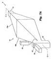
図7は、コントラスト改善照明器で用いるための本発明の変形例を示しているが、図6の実施形態と構成が同様であるが、カメラ38を拡散構造物14外部に配置する。カメラ38の位置が違って図7のホットミラー54は図6に比べて時計方向に90度回っているが図6と同様に機能する。また、赤外線フィルター42を導光部22壁面に設置して、照明源12の光が導光部22出口23に向かうように反射板60を設置する。好適には、反射板60は平面形でありながら物体32とカメラ38とプロジェクター50間に光が過ぎ去ることができるように穴があけられた。 FIG. 7 shows a modification of the present invention for use in a contrast-enhanced illuminator, but is similar in configuration to the embodiment of FIG. 6, but the
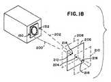
比較的小型であって信頼性が高い撮影装置70が図8〜図11に示された。この撮影装置70は体組織のような物体71で反射された赤外線を根拠にして物体のビデオ画像を作ることであって、ハウジング72の中に装置の撮影要素が入っている。 A relatively small and highly reliable photographing apparatus 70 is shown in FIGS. The photographing device 70 is to create a video image of an object based on infrared rays reflected by an object 71 such as a body tissue, and a photographing element of the device is contained in a housing 72.
図8で、ハウジング72は直六面体で、長さは3〜5インチであって幅は3.5インチ程度である。当業者ならば分かるだろうが、この撮影装置70はここで説明した例に限定されなくて、直六面体でない円形や、多角形等の他の形状を有することができる。 In FIG. 8, the housing 72 is a rectangular parallelepiped, has a length of 3 to 5 inches and a width of about 3.5 inches. As will be appreciated by those skilled in the art, the imaging device 70 is not limited to the example described here, and may have other shapes such as a circle that is not a hexahedron or a polygon.
レンズ75が付いているビデオカメラのように、ビデオカメラ74はハウジング72の中に配置されて、物体71から出る赤外線を感知及び処理する機能をする。カメラ74は物体71で反射された赤外線を根拠にして画像を作る。図8、図9に示したように、カメラ74は設置壁面78の穴76内に設置されるが、この時レンズ75はハウジングの内部77に入るが、これに対しては後述する。具体的にカメラ74は好適には、ハウジング72の中の中央に対称で設置されることが良い。この場合、カメラが感知した光量が最大化されて画像の品質が改善されるので、結局体組織内皮下脂肪下の皮下血管の画質が改善される。 Like a video camera with a lens 75, the
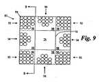
装置70の拡散光を物体71に送る各種要素をハウジング72の中に入れることが良い。矢印80は装置70から出た拡散光であって、矢印82は物体71の反射光である。図9は、図8のA−A線断面図であって、ウェル(78:well)の中に複数個の赤外線LED84をLEDアレイ85状に配列して赤外線を出す。LEDアレイ85はLED平面を形成する。それぞれのLED84は作動した時740nm程度の波長の光を放出する。LED84ではオーストリアRoithner Laser technikで製造したモデル番号ELD−740−524が良い。 Various elements that send the diffused light of the device 70 to the object 71 may be placed in the housing 72. An
図10と好適な実施形態によれば、LED84をウェル78の横にある回路基板86に設置する。図9によればLED84を8個グループ92、94にしてカメラ74周りに同心で配列する。このように同心でLEDを配列すると装置70の拡散光を最大に分散させることができる。LEDグループ92、94ごとのLED84個数は10個以上だが、場合によってはそれ以上であるか以下にすることもできる。また、LEDアレイ85のLEDグループ数も多かったり少なくすることができる。 In accordance with FIG. 10 and the preferred embodiment, the LEDs 84 are placed on a circuit board 86 next to the
4個のLEDグループ92はLEDアレイ85の角96に位置して、各グループのLED数は15個以上が良い。LEDアレイ85の横面98には4個のLEDグループ94が配置されて、各グループのLED数は10個以上が良い。 The four
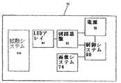
LEDアレイ85を回路基板86に配置することが最も良い。制御システム90のように、回路基板86の制御回路はLEDグループ92、94のLED84の動作を制御する。図11のように、マイクロプロセッサーのような制御システム90と電源88を回路基板86に連結する。制御システム90なくてもLEDを制御することができるが、例えば電源88をオン/オフにすることでLEDアレイ85を点けるか消すことができる。好適なデューティーサイクル(duty cycle)に合うようにLEDアレイ85のLED84を作動させるのに電源88と共にパルス変調技術も利用することができる。 It is best to arrange the LED array 85 on the circuit board 86. Like the
図11は、撮影装置70のブロック図で、LEDアレイ85が回路基板86を介して電源88と制御システム90に連結される。制御システム90はLEDアレイ85を制御して物体71に赤外線を断続的でも連続的に照らす。すなわち、LED84を一つや複数個選択して制御して物体71に赤外線を断続的でも連続的に照らす。したがって、撮影装置70はLEDグループ92、94やLED84自らの多様な配置や組み合わせに合うようにLEDアレイから赤外線を放出する。 FIG. 11 is a block diagram of the photographing apparatus 70, and an LED array 85 is connected to a
図10を見ると、LEDアレイ85のLED放出面102に接するように第1拡散層100を配置するが、接着剤で接着して、LEDの光を拡散させるのに、Physical Optics Corporationで製作したLSD20PC10−F10x10/PSAという商品のようなホログラフィック20度ディフューザーが最も良い。第1拡散層100は長さ3.5インチ、幅3.5インチ、厚さ0.1インチが良い。LED84が作動すると、LEDアレイ85から放出された赤外線が第1拡散層100で拡散して赤外線に第1拡散量を提供する。 Referring to FIG. 10, the
ハウジング104の内面104を白色ペイントなどでコーティングして、第1拡散層100で既に拡散した光を反射させると共にさらに拡散させる。第2拡散層106は間隔LDDぐらい第1拡散層100から離れる。第1、第2拡散層の間隔LDDは3インチ程度が適当だ。第2拡散層もホログラフィック20度ディフューザーが良い。第2拡散層は長さ3.5インチ、幅3.5インチ、厚さ0.1インチだ。 The
第2拡散層106は第1拡散層100から出て内面104で反射された既存拡散光をもう一度拡散する。図8に示したように、第1、第2拡散層は平面である。 The second diffusion layer 106 once again diffuses the existing diffused light that has exited the
図10を見れば、美合衆国デラウェア州ウィルミントン市のDuPontで製作したLUCITEのような支持層108を第2拡散層106横に配置する。支持層108横には偏光板110を配置するが、美合衆国イリノイ州のVisual Pursuitsで製作したVP−GS−12Uが最も良くて、その厚さは0.075インチである。 Referring to FIG. 10, a
この装置70は第1拡散層100を介して出た光を拡散して、第1隔室72aの内面104で反射した次に第2拡散層106と支持層108と偏光板110を介して続けて進行させて光を多くの段階に拡散する。したがって、第1拡散層100と内面104と第2拡散層106を経ながら拡散度はそれぞれ異なる。 The device 70 diffuses the light emitted through the
図8のように、偏光板110の中央部112は直径1インチの円形であることが好ましい。中央部112は形状と大きさがカメラレンズ75に一致して、その偏光方向が周り114の偏光方向と90度を有することが良い。カメラレンズ75は支持層108に接する。図8で、レンズ75はハウジング70内部にありながら偏光板110の中央部112と中心軸が一致する。レンズ75の正面に偏光板の中央部112を一致させて表面に生じる全ての正反射(specular reflection)を減らすことができる。 As shown in FIG. 8, the central portion 112 of the
図10に示したように、支持層108と偏光板110の平面の方向は第1、第2拡散層100、106の平面方向と同様なものが良いが、最も良いことは第1拡散層100、内面104、第2拡散層106、支持層108及び偏光板110が物体71に拡散光を提供する拡散システム116を構成することである(図10参照)。本発明の拡散構造はこれに限定されなくていくつの要素をさらに追加したり引くことができる。例えば、偏光板110やどの一側拡散層をなくしたり、偏光板のみなくすことができる。 As shown in FIG. 10, the plane direction of the
作動した撮影装置70はカメラ74で物体71に拡散光80を照らしてビデオ画像を作る。具体的に、電源88が作動すればLEDアレイ85のLED84で赤外線を放出する。第1拡散層100は放出された赤外線の第1拡散量を決定する。内面104は第1拡散層100から出た拡散光をさらに拡散させて、第2拡散層106はこの拡散光をさらに拡散させて支持層108と偏光板に送る。前述したように、物体71は放出された拡散光80を反射して拡散反射光82を出して、この光をカメラ74がキャプチャーして物体71のビデオ画像を作る。したがって、撮影装置70は血管と組職間にあるさまざまな物体の物質特性を区分するのに助けを与える。 The activated photographing device 70 illuminates the object 71 with the diffused
当業者ならば分かるだろうが、以上説明した本発明の実施形態は本発明の範囲内で変形や変更が可能である。例えば、拡散層100、106平面を互いに平行でないように調整して撮影装置70の拡散光をさまざまなレベルに提供することができる。また、LEDアレイ85平面を拡散層100と平行するようにすることが良いが、多様な角度で配置することもできる。したがって、以上の説明はあくまでも例を挙げたことであるだけであって、本発明の範囲を限定するのではないことを知らなければならない。 As will be understood by those skilled in the art, the embodiments of the present invention described above can be modified and changed within the scope of the present invention. For example, the diffusion layers 100 and 106 can be adjusted so that the planes are not parallel to each other, and the diffused light of the imaging device 70 can be provided at various levels. The plane of the LED array 85 is preferably parallel to the
図20は、皮膚に光を投射して撮影した皮下血管の画像を示す写真である。 FIG. 20 is a photograph showing an image of a subcutaneous blood vessel taken by projecting light onto the skin.
照明源、物体の表面下の内部構造の画像を示すカメラ、処理された画像を物体表面に投射し返すプロジェクターの構成も多様にすることができる。本発明の全ての実施形態が多くの構造的特徴を共有しているので、構造的に差が生じる部分に対してだけ説明して、同一だったり同様な構造に対する説明は今後省略する。 The configuration of the illumination source, the camera that shows the image of the internal structure under the surface of the object, and the projector that projects the processed image back onto the object surface can be varied. Since all the embodiments of the present invention share many structural features, only portions where structural differences occur will be described, and descriptions of the same or similar structures will be omitted in the future.
物体の内部構造の画像を遠く離れたモニターやスクリーンではない物体表面に再び投射するという点で本発明が既存の技術と異なるため、本発明のユーザーは光軸のずれによる従来の装置の視差を経験しない。カメラで撮影した内部構造の画像の一番目スペクトラムが物体表面に投射し返された画像の二番目スペクトラム範囲外において、カメラが物体表面に投射し返される画像に遮られるようにすることが本発明の重要な特徴である。内部構造画像のスペクトラムと投射された画像のスペクトラムが重ならなければ、内部構造の画像処理時投射された画像により干渉されないように效果的に分離することができる。投射された画像は可視光スペクトラムにあってカメラの照明は赤外線スペクトラムにあるので、このような非重畳関係を維持することができる。一方、物体を赤外線ではない広帯域周辺光で照明するが、赤外線フィルターをカメラ前に設置して赤外線外の成分は濾過するようにすると、カメラが物体で反射された広帯域拡散光の赤外線成分だけを見ることができる。 Since the present invention is different from the existing technology in that the image of the internal structure of the object is projected again on the object surface that is not a monitor or screen at a distance, the user of the present invention can view the parallax of the conventional device due to the optical axis shift I don't experience it. The present invention is such that the first spectrum of the image of the internal structure photographed by the camera is blocked by the image projected and returned to the object surface outside the second spectrum range of the image projected and returned to the object surface. Is an important feature. If the spectrum of the internal structure image and the spectrum of the projected image do not overlap, it can be effectively separated so as not to be interfered by the projected image during the internal structure image processing. Since the projected image is in the visible light spectrum and the camera illumination is in the infrared spectrum, such a non-overlapping relationship can be maintained. On the other hand, if an object is illuminated with broadband ambient light that is not infrared, but an infrared filter is installed in front of the camera to filter out components outside the infrared, only the infrared component of the broadband diffused light reflected by the object is reflected by the camera. Can see.
本発明の三番目撮影装置130が図12に示された。カメラでは既存のレンズが付いているCCDカメラ132を用いる。物体の反射光とCCDカメラ間に第2偏光フィルター134を配置して、物体表面における正反射を減らす。照明源、第1偏光フィルター、ホログラフィック拡散リング、ガラスカバーは全て136で表示した部分に配置されて、図13、図14に示された四番目撮影システムで詳細に説明する。 A
同様に、プロジェクター138で物体Oに画像を投射する。投射された画像を普通の室内照明でどれほどよく見られるかを決定する因子がプロジェクターの出力光強度であるのでプロジェクター138は出力光強度が高くなければならない。プロジェクター138の高強度緑色LED照明源140がプリズム142に光を照らすと、プリズム142の内部反射により光が折れてDMD(Digital Mirror Device)のようなDLP(Digital Light Processing)装置144に向かう。DLP装置には小型ミラーがびっしり配置されていて入射光を投射レンズ146を介して標的物体に照らしたり照らせないことがあって、当業者によく知られた画素基盤にして光を送ることができる。プリズム142を用いると装置を小型化できて、このようなプリズムは当業者によく知られている。 Similarly, an image is projected onto the object O by the
前述したように、いわゆるホットミラー148を45度角度で設置して物体で反射された赤外線をカメラ132に向かって反射する。ホットミラー148は赤外線のような長波長の光は反射するが、プロジェクター138の緑色光のような高周波光は通過させる。 As described above, the so-called
標的をカメラ132の焦点位置にまともに配置するために二個のレーザ150、152をさらに設置するが、これに対しては後に詳細に説明する。 Two
図13、図14では本発明の四番目撮影装置154に対して説明する。この装置154は移動式カート158で上に立てられてあるポール156に設置されるので、運搬が容易である。精密焦点ステージ160に撮影装置154を置いて昇降させながら標的物体O上に撮影装置をまともに置くことができる。プロジェクター162にはDMD/DLPチップ166を照らすための525nm緑色LED照明源164を設置する。本実施形態に適当な照明源164は強度85ルーメンのTeledyne Lighting model PE09−G照明器が良い。DMDチップ166はTexas Instrumentsの0.7SVGA SDR DMDチップがよいが、このチップは解像度が848X600画素であってミラー傾斜は10度でありフレーム率は30Hzである。プリズム168内部で照明源164の光が反射されてDMDチップ166に向かったが、ここで物体Oに向かって反射される。DMDチップ166はOptical Sciences Corporation製作の公知の電子基板167により調節する。 13 and 14, the
照明源164とプリズム168間に集光レンズ170を配置するが、主にOptoSigmaで販売するモデルナンバー013−2790−AZ55を用いるが、このレンズの表面には425−675nm光に対備してBBAR/ARをコーティングする。プロジェクターの光がプリズム168から出て公知の投射レンズ(172:例、Beslerモデル番号8680)を通過した次にホットミラー174に行くが、ホットミラーは物体Oから受けた赤外線画像を第2偏光フィルター178を介してカメラ176側に反射する。適当なカメラ176はPoint Grey Researchで販売するFirefly Cameraでモデル番号FIRE−BW−XXであって、IEEE−1394インターフェースを介してCPU180に画像を送る。CPU180の多くのインターフェース信号181は当業者によく知られた方式で撮影装置に送られる。同様に、四番目実施形態においても物体Oをカメラ176の焦点にまともに置くために二個のレーザ150、152を利用する。 A
四番目の撮影装置154も赤外線照明源182、第1偏光フィルター(184:プロジェクターの映像や物体の画像に影響を与えないように真ん中が空いた環形である)、LED190の光を拡散するホログラフィック拡散リング(186:同様に真ん中が空いている)及びガラスカバー188を有する。赤外線照明源182は円形のような形状で複数個のLEDが配列されたものであって、中央の空いた空間を投射画像と物体の画像が通過する。LEDでは物体Oに光を照らす740nm近赤外線LED190が良いし、研究によるとこのような構造では赤外線を拡散して物体を十分に照らすことができる。 The
これから、図15を参照して本発明の五番目撮影装置192に対して説明する。本実施形態では他の実施形態のようにLED190が付いている照明源182を用いて物体を照らすことでなく、さらに広いスペクトラムの周辺光Lや太陽光Sを利用するという点で差がある。周辺光は若干の赤外線成分を有して相当な拡散をするが、このような赤外線成分はその強度が照明源の赤外線よりはるかに低い。したがって、本実施形態では性能がさらに良いカメラが必要である。 The
本実施形態の装置192も同様にプロジェクター162、緑色照明源164、プリズム168、投射レンズ172及びDMDチップ166を有する。小型化のために他の実施形態のようにフォールドミラー(194:fold mirror)を利用して照明源164とプリズム168間のプロジェクター内部で光を直角で折る。本実施形態でもホットミラー174を利用する。ここでは、カメラ198と物体O間の光経路に赤外線フィルター196を配置してカメラが撮影した画像の赤外線成分を濾過する。カメラ198ではドイツBasler Vision Technologies社のモデルナンバーA600−HDRを用いることが良い。本実施形態の装置はさらに明るい室内で用いることができるという長所を有する。 Similarly, the
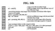
実験によるとある人は腕と脚に毛が多くて皮膚表面に投射される皮下構造を鮮明に見ることが難しい。全ての毛、白毛さえも近赤外線では黒く見える。したがって、血管のように大きく暗い部分はそのまま維持しながら毛のように小さくて暗い細かいほこり部分は除去するように画像を処理する。図16A、図16Bは順番どおり見えるプログラムであって、受信された画像で細かいほこりを処理するためのプログラムである。同じ細かいほこりの除去過程を2回実施した次に、適応的エッジ強調(adaptive edge enhancement)過程を介してアンシャープマスキング(unsharp masking)をした次に平滑法(smoothing)を介して画像の細かいほこりをなくす。このプログラムは画像処理分野の当業者にはよく知られたものである。 According to experiments, it is difficult for a person to clearly see the subcutaneous structure projected on the skin surface with a lot of hair on the arms and legs. All hair, even white hair, looks black in the near infrared. Therefore, the image is processed so as to remove small and dark dust portions such as hair while maintaining large dark portions such as blood vessels. FIG. 16A and FIG. 16B are programs that can be viewed in order, and for processing fine dust in the received image. The same fine dust removal process was performed twice, followed by unsharp masking through an adaptive edge enhancement process, followed by smoothing (smoothing). Is lost. This program is well known to those skilled in the image processing field.
画素値が整数範囲(0....255)にある受信画像が0.0と1.0間の不動小数点値に変換される。変換された画像はシグマ値が8画素であるガウス回旋(Gaussian convolution)を利用して平滑化される。このように平滑化された画像はシグマ値が相当に小さくて非常に小さい毛のような小さな細かいほこりが残る。本来の画像からガウス平滑画像を引いた“差分画像(difference image)”を作って0を中心にして−1.0から1.0までの値を作る。白毛を含んだ全ての毛は近赤外線で暗く現われるので、陰の画素値はこのような毛を現わして、これに伴いこのような負数値画素はガウス平滑画像で該画素に置き換える。この段階が一番目画像処理段階である。次に、この画像のための一連の値を生成して、本来の“差分画像”で負数値を有していた全ての画素の位置(すなわち、“毛”の位置)を1.0で設定してその外他のすべての画素の位置は0で設定して、0.0と1.0の値が分布したアレイを作るのに、ここで毛を現わす画素は1.0の値を有して他の画素は0の値を有する。次に、0.0から1.0間の画素値を有する本来画像(“iml”)を全ての“毛画素”位置で0.015倍“ブースト(boost)”する。これが高度の非線形作業であるので、“ブースト”量はやっと1.5%である。 A received image with pixel values in the integer range (0 ... 255) is converted to a fixed point value between 0.0 and 1.0. The converted image is smoothed using a Gaussian convolution having a sigma value of 8 pixels. In such a smoothed image, sigma values are considerably small and small fine dust such as very small hair remains. A “difference image” is obtained by subtracting a Gaussian smooth image from the original image, and a value from −1.0 to 1.0 is created around 0. Since all hairs including white hair appear dark in the near-infrared, shadow pixel values appear such hairs, and as such, such negative value pixels are replaced with Gaussian smoothed images. This stage is the first image processing stage. Next, a series of values for this image is generated, and the positions of all the pixels having negative values in the original “difference image” (ie, “hair” positions) are set to 1.0. Then, the position of all other pixels is set to 0, and an array in which values of 0.0 and 1.0 are distributed is created. Other pixels have a value of 0. Next, the original image (“iml”) having a pixel value between 0.0 and 1.0 is “boosted” by 0.015 times at all “hair pixel” positions. Since this is a highly non-linear task, the “boost” amount is only 1.5%.
同じ作業過程(ガウス平滑、差分画像生成、負数値画素位置確認、負数値画素(細かいほこり)が発見された画像の“ブースト”)を繰り返して、その画像を再びシグマ64画素のガウス回旋で平滑化する。平滑画像で“ブースト”画像を再び引いた3番目差分画像を作って、この差分画像の全ての画素の絶対値で形成された画像を作る。このような絶対値画像を再びシグマ64画素のガウス回旋で平滑化して、3番目差分画像を平滑化された絶対値画像で割って生じた分割画像を再びシグマ4画素のガウス回旋で平滑化する。 Repeat the same work process (Gaussian smoothing, differential image generation, negative value pixel position confirmation, “boost” of the image where negative value pixels (fine dust) are found), and smooth the image again with Gaussian rotation of 64 sigma pixels Turn into. A third difference image obtained by redrawing the “boost” image with the smooth image is created, and an image formed by the absolute values of all the pixels of the difference image is created. Such an absolute value image is again smoothed by Gaussian rotation of sigma 64 pixels, and the divided image obtained by dividing the third difference image by the smoothed absolute value image is again smoothed by Gaussian rotation of
以上の細かいほこりの除去アルゴリズムを介して細かいほこり(毛)がない皮下血管(標的皮下構造)のコントラストを設定して、適応的アンシャープマスキングエッジ強調(adaptive unsharp masking edge enhancement)のための画像を準備して最終画像のコントラストを設定することができる。シグマ値や臨界値のような変数は対象の年齢、着色度などによって変わることができる。 Set the contrast of subcutaneous blood vessels (target subcutaneous structure) without fine dust (hair) through the fine dust removal algorithm above, and image for adaptive unsharp masking edge enhancement You can prepare and set the contrast of the final image. Variables such as sigma values and critical values can vary depending on the age of the subject, the degree of coloring, and the like.
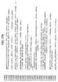
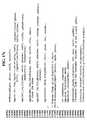
図17a〜図17fは順序通り表示したことであって図16のプログラムを基盤にして受信された画像の細かいほこりの除去のためにC++言語で表示したプログラムであるが、さらに迅速な数学計算のためにインテル画像処理ライブラリー(IPL:image processing library)を利用する。 FIGS. 17a to 17f are displayed in order, and are programs displayed in the C ++ language for removing fine dust of images received based on the program of FIG. For this purpose, an Intel image processing library (IPL) is used.
本発明の全ての実施形態は皮下構造の画像をカメラ、特にレンズと物体間の距離が適切なカメラに見えるまま維持するメカニズムを有する。図18に示したように、このようなメカニズムでは一対のレーザ150、152を利用するが、レーザそれぞれのレーザービーム200、202は相異なる角度で物体に向かって集るが、標的がカメラから適当な距離である図面の平面206位置にある時二個のレーザービームが会って一点204に現われる。標的が適正距離以上カメラに近くあったり(図面で208平面)遠くあれば(図面で210平面)、二個のレーザービームが第1双点212、214や第2双点216、218形態で各々208平面や210平面で物体表面に現われて、物体表面に一点204に集まった形態に見えないのに、これは皮下構造物がカメラの焦点になくて皮下構造物の画像焦点を合せようとするならカメラと物体の距離に変化を与えなければならないことを意味する。このようなレーザ150、152は図12〜図14でも見ることができる。本発明に用いるのに適当なレーザはオーストリアウィーン所在Roithner Lasertechnik社のモデル番号LM−03がある。 All embodiments of the present invention have a mechanism that maintains an image of the subcutaneous structure while the distance between the lens and the object remains visible to the appropriate camera. As shown in FIG. 18, such a mechanism uses a pair of
標的位置追跡メカニズムの2番目実施形態は観察される内部構造と関係なしでテキストボーダー(text border)のような認識パターンを投射画像に追加する。投射された認識パターンは標的物体がプロジェクターから適当な距離にある時標的物体の表面に焦点を結んで肉眼によってのみ認識されるので、標的物体表面下の内蔵構造物をカメラから適当な距離に置くことができる。必要によって子供が好む漫画人物や病院のロゴを適切に認識パターンで用いることができる。埋立構造物の投射画像が細かいほこりの除去過程で薄暗くなる間、認識パターンの焦点がぼけるならば肉眼でこれをすぐ気付くことができる。このような2番目実施形態の長所は、レーザでない認識パターンを用いるということであって、レーザを用いる場合適切な安全措置を行なわないと視覚喪失のような深刻な損傷を受けることができる。 A second embodiment of the target location tracking mechanism adds a recognition pattern, such as a text border, to the projected image regardless of the observed internal structure. Since the projected recognition pattern focuses on the surface of the target object and is recognized only by the naked eye when the target object is at an appropriate distance from the projector, the built-in structure below the target object surface is placed at an appropriate distance from the camera. be able to. If necessary, cartoon characters preferred by children and logos of hospitals can be appropriately used as recognition patterns. While the projected image of the landfill structure becomes dim during the fine dust removal process, this can be immediately noticed by the naked eye if the recognition pattern is out of focus. The advantage of such a second embodiment is that it uses a recognition pattern that is not a laser, and can suffer severe damage such as vision loss if proper safety measures are not taken when using a laser.
図21は、テキストボーダーで囲んだ投射画像の写真である。 FIG. 21 is a photograph of a projected image surrounded by a text border.
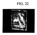
図22は、図21と同様にテキストボーダーで囲んだ投射画像の写真であるが、この写真では撮影画像が自分の位置を外れてテキストボーダーの焦点が合わないし、これは物体がカメラに対してまともに位置していないことを意味する。 FIG. 22 is a photograph of a projected image surrounded by a text border as in FIG. 21. In this photograph, the photographed image is out of its position and the text border is not focused. It means that it is not properly located.
図23は、投射画像に結合されて共に物体に投射されるテキストボーダーを示している。プリズム内部で画像が反射される場合起きる画像反転のため、ここではテキストボーダーが反転されたことに見えるが、投射された時はまともに見える。投射画像をテキストボーダーと結合する前に適切に裁断して鮮明に区分するようにする。 FIG. 23 shows a text border that is combined with the projected image and projected onto the object together. Because of the image reversal that occurs when the image is reflected inside the prism, it appears here that the text border has been reversed, but it looks decent when projected. Before combining the projected image with the text border, it is appropriately cut so that it is clearly divided.
図24は、本発明により手に光を照らした時の皮下血管処理画像の写真であって、(テキストボーダーが抜けた)図20及び図21と同様であるが、テキストボーダーは焦点が合わなくて手がまともに位置しない状態である。 FIG. 24 is a photograph of a subcutaneous blood vessel processing image when light is illuminated on the hand according to the present invention, which is similar to FIGS. 20 and 21 (with the text border missing), but the text border is not in focus. The hand is not properly positioned.
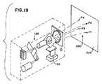
図19は、ビデオプロジェクター138、162が蛍光スクリーン222に緑色標的パターン220を投射する補正方法を示すが、ここでは投射された4−ドット緑色標的パターン220を赤外線カメラ132で見ることができる赤紫色光に変える。コンピュータプログラムにより4箇所投射ドットP1〜P4のパターン位置が直角座標である(x1、y1)、(x2、y2)、(x3、y3)、(x4、y4)で記録されて、整列状態が正しいドットの希望する位置は(X1、Y1)、(X2、Y2)、(X3、Y3)、(X4、Y4)で記録されて、(図25azと図25bの関数を解くための)双線形変換方程式に用いられる歩程計数(a、b、c、d、g、h、k、f)を計算してカメラとプロジェクター間の倍率、回転及び誤整列を修正する。図25a〜bでは補正中に測定した値の関数で双線形変換係数を解決するのにMAPLE9コンピュータ方程式を利用することを示す。このような補正係数は画像の座標(x、y)を補正された画像を作るのに必要な修正された座標(X、Y)に変換するのに用いられる。図26は、一回補正されたこれら座標値をインテル社のプロセッサで提供する既存の画像処理ライブラリー数学ルーチンに用いて双線形変換方程式による高性能画像整列修正をする方法を示す。高速画像処理のために浮動小数点ではない整数算術法を利用したランタイム計算をする。 FIG. 19 shows a correction method in which the
こういう補正過程を介してそれぞれ(カメラで見て)320x240画素の大きさを有する直四角形の角半径が(カメラで見て)25画素である4個のドットP1〜P4で構成されたテストパターン220を蛍光スクリーンに投射する。例えば、カメラ132の解像度は640x480画素であるが、、プロジェクター138の解像度は1024x780画素である。半径が4〜50画素であるドットに対する実験によると、100個サンプルの標準偏差は半径5画素のドットで25画素の画素まで急激に減少したし、半径50画素を越えればはるかに徐々に減少した。 Through such a correction process, a
本発明の補正法を実施するために、互いに離れた4個のドット(P1〜4)でなったテストパターンを第1スペクトラム(緑色光が良い)で蛍光スクリーン222に投射すると、赤外線やそれに近い第2スペクトラムの光、例えばカメラ132で見る赤色光が生じるのに、はなはだしくはカメラが赤外線透過フィルターを介して標的物体を見ることができる。続いて、補正ソフトウェアを利用して4個ドットの観察位置を測定して双線形変換方程式の修正係数(a、b、c、d、g、f、h、k)を計算して、これら係数を双線形変換の変数で利用してカメラとプロジェクター間の誤整列エラー(回転、移動、拡大)を修正するのに、この時投射画像の誤整列修正のために投射以前にあらかじめ画像をよじておく。このような過程は水平垂直方向に相異なった拡大エラーや移動エラーを修正できる。 In order to implement the correction method of the present invention, when a test pattern composed of four dots (P1 to P4) that are separated from each other is projected onto the
テストによれば、このような補正過程を経てカメラの画素サイズの半分範囲内で±25.4mmまで誤整列を修正できる。テストパターンの4個ドット付近の画像が整列されて全体的によさそうに見えることが最善である。 According to the test, the misalignment can be corrected up to ± 25.4 mm within the half range of the pixel size of the camera through such a correction process. It is best that the images near the four dots of the test pattern are aligned and look good overall.
全ての実施形態の特徴がいままでの説明で理解したこととは異なるように用いられることもできる。例えば、別途の拡散赤外線を用いなくて周辺光の赤外線成分を物体に照らしたり、カメラから物体まで希望する距離を維持するのに皮下構造物の投射画像に認識パターンを結合したり別途の標的検索器を用いることもする。 The features of all the embodiments may be used differently from what has been understood in the foregoing description. For example, illuminate the object with the infrared component of ambient light without using separate diffused infrared, or combine the recognition pattern with the projected image of the subcutaneous structure to maintain the desired distance from the camera to the object, or search for a separate target A vessel is also used.
以上説明したように、本発明の装置と方法では、受信画像を標的に投射し返す前に多様な画像処理技術を利用して受信画像を視覚的に改善することができる。例えば、アンシャープマスクを採択した細かいほこりの除去処理を利用して本来の画像(焦点が生じた画像)からぼかした部分を除去してエッジが強調された画像を作ることができる。もちろん、他の技術も利用することができる。 As described above, with the apparatus and method of the present invention, the received image can be visually improved using various image processing techniques before the received image is projected back to the target. For example, it is possible to create an image in which edges are emphasized by removing a blurred portion from an original image (an image having a focus) using a fine dust removal process employing an unsharp mask. Of course, other techniques can be used.
図27Aは、本発明によって物体の映像でコントラストを改善する方法の順序図である。27−1段階で、画像処理器であるカメラで映像データが受信される。映像データは既存のデジタルフォーマット、例えば0−255グレースケールの画素データで処理される。27−2段階で、ぼかしフィルターを利用してぼけた画像を作る。このようなぼけ(blurring:ぼかすように処理すること)は速度改善のためにコンボリューション(convolution)を介して空間ドメインや周波数ドメインで起きる。27−3段階で本来の画像でぼけた画像を抽出して、アンシャープマスクを作る(27−4段階)。アンシャープマスクの絶対値(ABS)を取って(27−5段階)、他のぼかしフィルターを用いる(27−6段階)。アンシャープマスクのぼけた絶対値でアンシャープマスクを分割して(27−7段階)、演算結果を調整して最終的に改善された画像を作る(27−8段階)。 FIG. 27A is a flowchart illustrating a method for improving contrast in an image of an object according to the present invention. In step 27-1, video data is received by a camera which is an image processor. Video data is processed in an existing digital format, for example, pixel data of 0-255 gray scale. In step 27-2, a blurred image is created using a blur filter. Such blurring occurs in the spatial and frequency domains via convolution to improve speed. In step 27-3, an image blurred by the original image is extracted to create an unsharp mask (step 27-4). The absolute value (ABS) of the unsharp mask is taken (step 27-5), and another blur filter is used (step 27-6). The unsharp mask is divided by the blurred absolute value of the unsharp mask (step 27-7), and the calculation result is adjusted to finally produce an improved image (step 27-8).
本発明によれば、画像の各画素に“平均窓(averaging window)”を適用してぼけた画像を作る。平均窓とは処理中の画像よりカーネルサイズ(kernel size)が小さな窓をいう。画像のそれぞれの画素を平均窓中心に置いて、関心画素の値を平均窓内部の画素全体の平均値にする。例えば、解像度が640x480画素である画像で、大きさが192x192である平均窓は1番目ぼかしフィルターのように良い結果を出すという。平均窓を画像境界線を越えて画像外部の画素に適用する時は平均窓の画素を複写して平均窓を満たす。 In accordance with the present invention, a blurred image is created by applying an “averaging window” to each pixel of the image. An average window is a window with a smaller kernel size than the image being processed. Each pixel of the image is placed at the center of the average window, and the value of the pixel of interest is the average value of all the pixels inside the average window. For example, an average window with a resolution of 640 × 480 pixels and a size of 192 × 192 gives good results like the first blur filter. When the average window is applied to pixels outside the image beyond the image boundary, the average window pixels are copied to fill the average window.
画像内各画素に平均窓を適用すると、ぼけた画像が作られる。図27Aの方法で、それぞれ他の2種類の時間にぼかしフィルターを適用したところ、サイズが小さい2番目ぼかしフィルターが1番目ぼかしフィルターよりもっと良い結果を得た。1番目平均窓のカーネルサイズは192x192画素であって、2番目サイズのカーネルサイズは96x96画素で画像のシャープネス(sharpness)効果がさらに良かった。当業者ならば分かるだろうが、空間ドメインで処理する場合カーネルサイズが小さいとさらに迅速な処理が可能であって、本発明は特定カーネルサイズに限定されない。 When an average window is applied to each pixel in the image, a blurred image is created. When the blur filter was applied to each of the other two types of times using the method of FIG. 27A, the second blur filter having a smaller size obtained better results than the first blur filter. The kernel size of the first average window is 192 × 192 pixels, the kernel size of the second size is 96 × 96 pixels, and the sharpness effect of the image is even better. As will be appreciated by those skilled in the art, when processing in the spatial domain, if the kernel size is small, faster processing is possible, and the present invention is not limited to a specific kernel size.
本発明によれば、線形縮尺法で最終コントラスト調整をする(27−8段階)。例えば、この段階以前に実行されたディビジョン機能の結果16ビット整数が生じて、この値は最小最大値を利用して8ビット整数で縮尺されることができる。縮尺過程間、最小(Min)及び最大(Max)変数がスプレッド(spread)を決定するので、コントラストの程度が増加する。ソース画素pと目的画素p’を描くのに利用される縮尺公式は: According to the present invention, the final contrast is adjusted by the linear scale method (step 27-8). For example, a division function performed before this stage results in a 16-bit integer, which can be scaled with an 8-bit integer using the minimum and maximum values. During the scale process, the Min and Max variables determine the spread, thus increasing the degree of contrast. The scale formula used to draw the source pixel p and the target pixel p 'is:
p’=dst_Min+k*(p−src_Min)であるが、 p '= dst_Min + k * (p-src_Min)
ここでk=(dst_Max−dst_Min)/(src_Max−src_Min)である。 Here, k = (dst_Max−dst_Min) / (src_Max−src_Min).
画像処理結果が図27B〜Cである。図27Bは、テスト標的の画像(勾配線)と、勾配線の選択区間の画素値グラフである。図27Cは、図27Aの過程で改善した後のテスト勾配線の画像と、勾配線の選択区間の後処理画素値グラフである。図面で見るように、勾配線の真ん中に暗い中心線があることのような詳細な画像が生じる。 The image processing results are shown in FIGS. FIG. 27B is an image (gradient line) of a test target and a pixel value graph of a selected section of the gradient line. FIG. 27C is a test gradient line image after improvement in the process of FIG. 27A and a post-processed pixel value graph of a gradient line selection section. As can be seen in the drawing, a detailed image is produced such that there is a dark centerline in the middle of the gradient line.
ぼけ段階のためにさらに小さい平均窓を図27Aの方法に適用するとさらに詳細な画像を得ることができる。サイズ96x96画素の1番目平均窓と48x48画素の2番目平均窓を27−6段階に適用するとさらに詳細な画像を得ることができる。 If a smaller average window is applied to the method of FIG. 27A for the blur step, a more detailed image can be obtained. A more detailed image can be obtained by applying the first average window of
画像処理をもっとして視覚的にさらに有用な皮下血管画像を作ることができる。例えば、縁や中心がさらに鮮明な血管の画像はコントラスト改善技術で作ることができる。図28Aは、画像のコントラストを改善するための他の方法の順序図である。28−1段階で処理する画像を受けると、28−2段階でぼかしフィルターを利用してぼけた画像を作る。28−3段階でぼけた画像を本来画像で抽出して、28−4段階でアンシャープマスクを作る。28−5段階でアンシャープマスクの絶対値を取って、28−6段階でぼかしフィルターを適用する。アンシャープマスクの絶対値は28−7段階でアンシャープマスクのぼけた絶対値に分割されて、その結果を調整して最終改善した画像を作る(28−8段階)。 More image processing can be used to create visually more useful subcutaneous blood vessel images. For example, an image of a blood vessel with a sharper edge or center can be created by a contrast improvement technique. FIG. 28A is a flow diagram of another method for improving image contrast. When an image to be processed in step 28-1 is received, a blurred image is created using a blur filter in step 28-2. An image blurred in step 28-3 is extracted as an original image, and an unsharp mask is created in step 28-4. The absolute value of the unsharp mask is taken in step 28-5, and the blurring filter is applied in step 28-6. The absolute value of the unsharp mask is divided into blurred absolute values of the unsharp mask in step 28-7, and the result is adjusted to produce a final improved image (step 28-8).
図28Aの方法で、それぞれサイズ76x76、40x40の1番目と2番目平均窓を利用すると結果がさらに良かったことが明らかになった。 It became clear that the results were even better when using the first and second average windows of size 76x76 and 40x40, respectively, with the method of FIG. 28A.
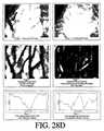
画像処理結果が図28B〜Dである。図28Bは、図28Aの過程で改善した後のテスト勾配線の画像と、勾配線の選択区間の後処理画素のグラフである。図面で見るように、勾配線の縁がさらに暗く見える詳細な画像が生じた。図28Cは、人間の腕に投射し返された皮下血管の改善した画像を示すのに、左側は図27Aの方法で、右側は図28Aの方法でそれぞれ生じたのである。当業者ならば分かるだろうが、2種類方法には明らかな差がある。 The image processing results are shown in FIGS. FIG. 28B is a graph of an image of a test gradient line after improvement in the process of FIG. 28A and a post-processing pixel of a selected section of the gradient line. As can be seen in the drawing, a detailed image was produced in which the edges of the gradient lines appeared darker. FIG. 28C shows an improved image of the subcutaneous blood vessel projected back onto the human arm, with the left side resulting from the method of FIG. 27A and the right side resulting from the method of FIG. 28A. As one skilled in the art will appreciate, there are clear differences between the two methods.
図28Dは、図28Aの各段階における人間の身体の画像である。上段左側画像は身体の本来画像、上段右側画像は身体のぼけた画像、中間左側画像は本来画像からぼけた画像を抽出した結果、中間右側は図28Aの処理結果詳細に改善した画像、下段の2グラフは真上の二個画像それぞれの画素データのグラフである。 FIG. 28D is an image of the human body at each stage of FIG. 28A. The upper left image is the original image of the body, the upper right image is the blurred image of the body, the middle left image is the result of extracting the blurred image from the original image, the middle right is the image improved in detail in the processing result of FIG. Two graphs are graphs of pixel data of the two images directly above.
図29Aは、本発明によって画像コントラストを改善する方法の順序図である。29−1段階でカメラから画像を受けて、29−2段階でぼかしフィルターを利用してぼけた画像を作って、29−3段階ではぼけた画像を本来の画像から抽出した次に、29−4段階でアンシャープマスクを作る。29−5段階でアンシャープマスクの絶対値を取ってぼかしフィルターを適用する(29−6段階)。アンシャープマスクのぼけた絶対値でアンシャープマスクを分割して(29−7)、その作業結果を調整して改善映像を作る(29−8)。次に、それぞれの画素を臨界輝度と比較する(29−9)。画素が臨界値より小さければ、この画素を最大レベルに設定する(例:0〜255のコントラストスケールで255)。 FIG. 29A is a flow diagram of a method for improving image contrast according to the present invention. In step 29-1, an image is received from the camera. In step 29-2, a blurred image is created using a blur filter. In step 29-3, the blurred image is extracted from the original image. Make an unsharp mask in 4 stages. In step 29-5, the absolute value of the unsharp mask is taken and a blur filter is applied (step 29-6). The unsharp mask is divided by the absolute value blurred by the unsharp mask (29-7), and the work result is adjusted to produce an improved image (29-8). Next, each pixel is compared with the critical luminance (29-9). If the pixel is smaller than the critical value, this pixel is set to the maximum level (example: 255 on a contrast scale of 0-255).
29Aの方法で、それぞれ96x96及び40x40大きさの1番目及び2番目平均窓を利用したところさらに良い結果を得た。 Even better results were obtained when the first and second average windows of size 96x96 and 40x40, respectively, were used with the 29A method.
画像処理結果が図29Bである。図29Bは、図29Aの過程で改善した以後のテスト勾配線の画像と、勾配線の選択区間の後処理画素値のグラフである。図面から分かるように、勾配線の縁が暗くて中央がさらに明るいコントラストによりさらに詳細な画像が生じる。 The image processing result is shown in FIG. 29B. FIG. 29B is a graph of the image of the test gradient line after the improvement in the process of FIG. 29A and the post-processing pixel value of the gradient line selection section. As can be seen from the drawing, a more detailed image is produced by the contrast of the dark edges of the gradient lines and the brighter center.
図30Aは、本発明によって画像のコントラストを改善する他の方法の順序図である。30−1段階でカメラで処理する画像を受ける。30−2段階ではぼけた画像がぼかしフィルターにより生成される。ぼけた画像が30−3段階で本来の画像から抽出されて、アンシャープマスクが作られる(30−4)。アンシャープマスクの絶対値が取られて(30−5)、ここにぼかしフィルターが適用される(30−6)。アンシャープマスクの絶対値でアンシャープマスクを分割して(30−7)、その結果を調整して改善した画像を作る(30−8)。次に、画像の各画素を調整して差値ぐらい減らしたり伸ばす。一例で、この値が定数ぐらい減少されて、その結果値であるマイナス値を再び適用する。例えば、グレースケールが0−255であって定数が30ならば、25の画像値が許容限度である−5に減少されて、この値を適用して250になる。差値を利用して画素値を伸ばすと、画素値が255ないし0になる。 FIG. 30A is a flow diagram of another method for improving image contrast in accordance with the present invention. In step 30-1, an image to be processed by the camera is received. In step 30-2, a blurred image is generated by the blur filter. The blurred image is extracted from the original image in step 30-3 to create an unsharp mask (30-4). The absolute value of the unsharp mask is taken (30-5), and a blurring filter is applied here (30-6). The unsharp mask is divided by the absolute value of the unsharp mask (30-7), and the result is adjusted to produce an improved image (30-8). Next, each pixel of the image is adjusted to reduce or increase the difference value. In one example, this value is reduced by a constant and the resulting negative value is applied again. For example, if the grayscale is 0-255 and the constant is 30, then 25 image values are reduced to the allowable limit of -5 and this value is applied to 250. When the pixel value is extended using the difference value, the pixel value becomes 255 to 0.
図30Aの方法で、それぞれ96x96及び40x40大きさの1番目及び2番目平均窓を利用したところさらに良い結果を得た。 In the method of FIG. 30A, better results were obtained when using the first and second average windows of 96 × 96 and 40 × 40, respectively.
画像処理結果が図30Bで、図30Aの過程で改善した以後のテスト勾配線の画像と、勾配線の選択区間の後処理画素値のグラフである。図面から分かるように、勾配線の縁が暗くて中央がさらに明るいコントラストによりさらに詳細な画像が生じる。図30Cは、人の腕に投射し返した皮下血管の画像であって、左側は図27Aの方法で処理された画像であって、右側は図30Aの方法で処理された画像である。当業者ならば分かるだろうが、両者間には明らかな差がある。 FIG. 30B is an image of the test gradient line after the image processing result is improved in the process of FIG. 30A and a graph of post-processing pixel values in the selected section of the gradient line. As can be seen from the drawing, a more detailed image is produced by the contrast of the dark edges of the gradient lines and the brighter center. FIG. 30C is an image of a subcutaneous blood vessel projected back onto a human arm, the left side being an image processed by the method of FIG. 27A and the right side being an image processed by the method of FIG. 30A. As those skilled in the art will appreciate, there is a clear difference between the two.
本発明の他の実施形態によれば、画像に“最大フィルター”を先に適用すると身体の毛のため生じる画像の細かいほこりや干渉を減らすことができる。最大フィルターはぼかしフィルターと同様であるが、各画素に平均窓ではない最大フィルター窓を適用するものだ。最大フィルター窓は関心画素をカバーする窓の全ての画素の最大値を確認して関心画素を最大値に設定する。サイズ12x12画素の最大フィルター窓中心に関心画素をおいたら良い結果が得られた。 According to another embodiment of the present invention, applying the “maximum filter” to the image first can reduce the fine dust and interference in the image caused by body hair. The maximum filter is the same as the blur filter, but it applies a maximum filter window that is not an average window to each pixel. The maximum filter window checks the maximum value of all pixels in the window covering the pixel of interest and sets the pixel of interest to the maximum value. Good results were obtained if the pixel of interest was placed at the center of the maximum filter window of size 12x12 pixels.
一例で、図27Aの方法に最大フィルター窓を適用すると画像に対する毛の影響を減らすことができる。それぞれ192x192、96x96サイズの1番目及び2番目平均窓を採択するとその結果が良かった。 In one example, applying the maximum filter window to the method of FIG. 27A can reduce the effect of hair on the image. The results were good when the first and second average windows of 192 × 192 and 96 × 96 sizes, respectively, were adopted.
ログビデオ信号やデジタルビデオ信号を利用してハードウェア、ソフトウェア、ファームウェアを組み合わせる等の既存の方法でデジタル画像処理ができる。既存のC言語のようなコンピュータ言語でなったプログラムで過程を処理することを例に挙げて本発明を説明したが、これはあくまでも例を挙げたことであるだけであって、本発明は特定コンピュータ言語に限定されない。 Digital image processing can be performed by existing methods such as combining hardware, software, and firmware using log video signals and digital video signals. Although the present invention has been described by taking an example of processing a process using a computer language program such as the existing C language, this is merely an example, and the present invention is It is not limited to computer language.
Claims (24)
Translated fromJapanese前記改善した画像を受けて前記体組織部分に投射するプロジェクターと、を含むことを特徴とする撮影システム。Infrared light reflected from the body tissue part is received in the form of an input image to generate an improved image of the body tissue part. The image is improved by enhancing the contrast, including applying an unsharp mask to the input image. And a projector that receives the improved image and projects it onto the body tissue part.
(b)前記入力画像のコントラストを強調して皮下構造物を示す改善映像を作る段階と、及び
(c)前記改善映像を体組織に投射して皮下構造物を重ねて見えるようにする段階と、を含むことを特徴とする皮下構造物の鮮明度改善方法。(A) receiving an infrared ray reflected by the body tissue to create an input image;
(B) enhancing the contrast of the input image to create an improved image showing a subcutaneous structure; and (c) projecting the improved image onto a body tissue so that the subcutaneous structure can be seen superimposed. And a method for improving the definition of a subcutaneous structure.
Applications Claiming Priority (2)
| Application Number | Priority Date | Filing Date | Title |
|---|---|---|---|
| US90106907P | 2007-02-14 | 2007-02-14 | |
| PCT/US2008/054029WO2008101129A1 (en) | 2007-02-14 | 2008-02-14 | System and method for projection of subsurface structure onto an object's surface |
Publications (1)
| Publication Number | Publication Date |
|---|---|
| JP2010517733Atrue JP2010517733A (en) | 2010-05-27 |
Family
ID=39690531
Family Applications (1)
| Application Number | Title | Priority Date | Filing Date |
|---|---|---|---|
| JP2009550140APendingJP2010517733A (en) | 2007-02-14 | 2008-02-14 | Apparatus and method for projecting subcutaneous structure onto object surface |
Country Status (7)
| Country | Link |
|---|---|
| US (1) | US20100177184A1 (en) |
| EP (1) | EP2114253A1 (en) |
| JP (1) | JP2010517733A (en) |
| KR (1) | KR20090113324A (en) |
| CN (1) | CN101686820A (en) |
| MX (1) | MX2009008653A (en) |
| WO (1) | WO2008101129A1 (en) |
Cited By (2)
| Publication number | Priority date | Publication date | Assignee | Title |
|---|---|---|---|---|
| KR101348063B1 (en)* | 2012-03-07 | 2014-01-03 | 진우현 | Vein-viewer System using the Difference of Infrared Ray Absorption Rate Based on Oxygen Saturation |
| US9235108B2 (en) | 2013-07-05 | 2016-01-12 | Panasonic Intellectual Property Management Co., Ltd. | Projection system |
Families Citing this family (49)
| Publication number | Priority date | Publication date | Assignee | Title |
|---|---|---|---|---|
| US8478386B2 (en) | 2006-01-10 | 2013-07-02 | Accuvein Inc. | Practitioner-mounted micro vein enhancer |
| US9492117B2 (en) | 2006-01-10 | 2016-11-15 | Accuvein, Inc. | Practitioner-mounted micro vein enhancer |
| US12295744B2 (en) | 2006-01-10 | 2025-05-13 | Accuvein, Inc. | Micro vein enhancer with two lasers and two optical detectors configured for removing surface topology |
| US11253198B2 (en) | 2006-01-10 | 2022-02-22 | Accuvein, Inc. | Stand-mounted scanned laser vein contrast enhancer |
| US8489178B2 (en) | 2006-06-29 | 2013-07-16 | Accuvein Inc. | Enhanced laser vein contrast enhancer with projection of analyzed vein data |
| US8255040B2 (en)* | 2006-06-29 | 2012-08-28 | Accuvein, Llc | Micro vein enhancer |
| US10813588B2 (en) | 2006-01-10 | 2020-10-27 | Accuvein, Inc. | Micro vein enhancer |
| US11278240B2 (en) | 2006-01-10 | 2022-03-22 | Accuvein, Inc. | Trigger-actuated laser vein contrast enhancer |
| US9854977B2 (en) | 2006-01-10 | 2018-01-02 | Accuvein, Inc. | Scanned laser vein contrast enhancer using a single laser, and modulation circuitry |
| US12408865B2 (en) | 2006-01-10 | 2025-09-09 | Accuvein Inc. | Vein imaging device with differential image resolution at the center and the extremities of the vein image |
| US8838210B2 (en) | 2006-06-29 | 2014-09-16 | AccuView, Inc. | Scanned laser vein contrast enhancer using a single laser |
| US10238294B2 (en) | 2006-06-29 | 2019-03-26 | Accuvein, Inc. | Scanned laser vein contrast enhancer using one laser |
| US12089951B2 (en) | 2006-01-10 | 2024-09-17 | AccuVeiw, Inc. | Scanned laser vein contrast enhancer with scanning correlated to target distance |
| US8463364B2 (en)* | 2009-07-22 | 2013-06-11 | Accuvein Inc. | Vein scanner |
| US8594770B2 (en) | 2006-06-29 | 2013-11-26 | Accuvein, Inc. | Multispectral detection and presentation of an object's characteristics |
| US8665507B2 (en)* | 2006-06-29 | 2014-03-04 | Accuvein, Inc. | Module mounting mirror endoscopy |
| US8730321B2 (en)* | 2007-06-28 | 2014-05-20 | Accuvein, Inc. | Automatic alignment of a contrast enhancement system |
| EP2261852B1 (en)* | 2008-03-06 | 2013-10-16 | Fujitsu Limited | Image photographic device, image photographic method, and image photographic program |
| US9061109B2 (en) | 2009-07-22 | 2015-06-23 | Accuvein, Inc. | Vein scanner with user interface |
| NZ626274A (en)* | 2010-05-04 | 2015-03-27 | Ethicon Llc | Laser cutting system and methods for creating self-retaining sutures |
| JP5507376B2 (en)* | 2010-07-28 | 2014-05-28 | 三洋電機株式会社 | Imaging device |
| US8996086B2 (en) | 2010-09-17 | 2015-03-31 | OptimumTechnologies, Inc. | Digital mapping system and method |
| US8780161B2 (en)* | 2011-03-01 | 2014-07-15 | Hewlett-Packard Development Company, L.P. | System and method for modifying images |
| US8947527B1 (en)* | 2011-04-01 | 2015-02-03 | Valdis Postovalov | Zoom illumination system |
| CN102871645A (en)* | 2011-07-11 | 2013-01-16 | 浙江大学 | Near-infrared imaging ultrasonic vascular therapeutic apparatus |
| CN102429640A (en)* | 2011-08-16 | 2012-05-02 | 谢幼宸 | Portable blood vessel display lamp |
| US8897522B2 (en)* | 2012-05-30 | 2014-11-25 | Xerox Corporation | Processing a video for vascular pattern detection and cardiac function analysis |
| US9072426B2 (en) | 2012-08-02 | 2015-07-07 | AccuVein, Inc | Device for detecting and illuminating vasculature using an FPGA |
| JP2015007739A (en)* | 2012-10-01 | 2015-01-15 | キヤノン株式会社 | Display divice and control method thereof |
| KR101617068B1 (en) | 2012-10-11 | 2016-05-02 | 이문기 | Image processing system using polarization difference camera |
| JP6071444B2 (en)* | 2012-11-07 | 2017-02-01 | キヤノン株式会社 | Image processing apparatus, operation method thereof, and program |
| US10517483B2 (en) | 2012-12-05 | 2019-12-31 | Accuvein, Inc. | System for detecting fluorescence and projecting a representative image |
| WO2014112393A1 (en)* | 2013-01-21 | 2014-07-24 | パナソニック株式会社 | Measuring device and measuring method |
| CN103126654A (en)* | 2013-02-05 | 2013-06-05 | 杭州柏拉图科技有限公司 | Detecting system for near-infared body surface blood vessel detector |
| BR112014028811B1 (en)* | 2013-03-19 | 2020-11-17 | Koninklijke Philips N.V. | imaging system, method for registering an image of an object in a spectral band of terahertz radiation through radiography and visualization of the image in visible light, and storage medium |
| JP6127207B2 (en)* | 2013-05-13 | 2017-05-10 | 執鼎医療科技(杭州)有限公司 | Blood vessel image positioning system |
| CN104414620B (en)* | 2013-08-23 | 2017-07-07 | 东莞市中健医疗设备科技有限公司 | Vein positioning method and device based on binocular camera shooting |
| CN104665852A (en)* | 2013-11-29 | 2015-06-03 | 上海西门子医疗器械有限公司 | Projection method, device and system of medical image |
| US9298076B2 (en) | 2014-01-05 | 2016-03-29 | Hong Kong Applied Science and Technology Research Institute Company Limited | Image projector |
| WO2015131026A1 (en) | 2014-02-27 | 2015-09-03 | Intuitive Surgical Operations, Inc. | System and method for specular reflection detection and reduction |
| US9968285B2 (en)* | 2014-07-25 | 2018-05-15 | Christie Digital Systems Usa, Inc. | Multispectral medical imaging devices and methods thereof |
| US9730649B1 (en)* | 2016-09-13 | 2017-08-15 | Open Water Internet Inc. | Optical imaging of diffuse medium |
| CN110383136B (en)* | 2016-12-30 | 2021-08-10 | 巴科股份有限公司 | System and method for 3D reconstruction |
| CN107411705A (en)* | 2017-04-05 | 2017-12-01 | 展谱光电科技(上海)有限公司 | Multispectral shooting and projection arrangement and method |
| KR20200008749A (en)* | 2018-07-17 | 2020-01-29 | 주식회사 아이원바이오 | Oral scanner and 3d overlay image display method using the same |
| CN108937992B (en)* | 2018-08-06 | 2020-10-23 | 清华大学 | An in-situ visualization system for X-ray fluoroscopic imaging and its calibration method |
| EP3968628B1 (en)* | 2019-06-25 | 2023-11-22 | Panasonic Intellectual Property Management Co., Ltd. | Projection system |
| CN110908232B (en)* | 2019-11-22 | 2025-08-08 | 合肥利弗莫尔仪器科技有限公司 | A position and angle adjustment device for infrared digital imaging mechanism |
| CN112529800B (en)* | 2020-12-07 | 2022-08-23 | 同济大学 | Near-infrared vein image processing method for filtering hair noise |
Citations (9)
| Publication number | Priority date | Publication date | Assignee | Title |
|---|---|---|---|---|
| JPH05237083A (en)* | 1991-11-22 | 1993-09-17 | Arch Dev Corp | Digital image system and digital imaging method |
| JPH0924053A (en)* | 1995-07-12 | 1997-01-28 | Fuji Photo Film Co Ltd | Surgical operation support system |
| JPH1127533A (en)* | 1997-07-07 | 1999-01-29 | Dainippon Screen Mfg Co Ltd | Contour emphasis method and its device |
| JP2000050081A (en)* | 1998-07-06 | 2000-02-18 | Eastman Kodak Co | Automatic tone control method by contrast gain control of edge |
| JP2003534030A (en)* | 2000-01-19 | 2003-11-18 | ハーバート・ゼーマン | Diffuse infrared imaging device |
| JP2005006318A (en)* | 2003-06-11 | 2005-01-06 | Agfa Gevaert Nv | Method and user interface for modifying at least one of pixel contrast and density of a processed image |
| JP2006102360A (en)* | 2004-10-08 | 2006-04-20 | Matsushita Electric Ind Co Ltd | Biological information presentation device |
| JP2006102110A (en)* | 2004-10-05 | 2006-04-20 | Matsushita Electric Ind Co Ltd | Blood vessel position presentation device |
| JP2007325656A (en)* | 2006-06-06 | 2007-12-20 | Matsushita Electric Ind Co Ltd | Image processing method and image processing apparatus |
Family Cites Families (11)
| Publication number | Priority date | Publication date | Assignee | Title |
|---|---|---|---|---|
| US8078263B2 (en)* | 2000-01-19 | 2011-12-13 | Christie Medical Holdings, Inc. | Projection of subsurface structure onto an object's surface |
| US20070156038A1 (en)* | 2000-01-19 | 2007-07-05 | Zeman Herbert D | Method to image the heart |
| US6980691B2 (en)* | 2001-07-05 | 2005-12-27 | Corel Corporation | Correction of “red-eye” effects in images |
| US20050157939A1 (en)* | 2004-01-16 | 2005-07-21 | Mark Arsenault | Processes, products and systems for enhancing images of blood vessels |
| US7035077B2 (en)* | 2004-05-10 | 2006-04-25 | Greatbatch-Sierra, Inc. | Device to protect an active implantable medical device feedthrough capacitor from stray laser weld strikes, and related manufacturing process |
| US8462384B2 (en)* | 2004-09-29 | 2013-06-11 | Apple Inc. | Methods and apparatuses for aesthetically enhanced image conversion |
| EP1650980A3 (en)* | 2004-10-20 | 2010-09-29 | FUJIFILM Corporation | Electronic endoscope apparatus |
| KR100621097B1 (en)* | 2005-04-20 | 2006-09-07 | 삼성전자주식회사 | Image processing method and image processing apparatus |
| US20070038118A1 (en)* | 2005-08-10 | 2007-02-15 | Depue Marshall Thomas | Subcutaneous tissue imager |
| US8838210B2 (en)* | 2006-06-29 | 2014-09-16 | AccuView, Inc. | Scanned laser vein contrast enhancer using a single laser |
| US20080298642A1 (en)* | 2006-11-03 | 2008-12-04 | Snowflake Technologies Corporation | Method and apparatus for extraction and matching of biometric detail |
- 2008
- 2008-02-14WOPCT/US2008/054029patent/WO2008101129A1/enactiveApplication Filing
- 2008-02-14EPEP08729923Apatent/EP2114253A1/ennot_activeWithdrawn
- 2008-02-14JPJP2009550140Apatent/JP2010517733A/enactivePending
- 2008-02-14USUS12/526,820patent/US20100177184A1/ennot_activeAbandoned
- 2008-02-14MXMX2009008653Apatent/MX2009008653A/ennot_activeApplication Discontinuation
- 2008-02-14KRKR1020097018766Apatent/KR20090113324A/ennot_activeWithdrawn
- 2008-02-14CNCN200880012041Apatent/CN101686820A/enactivePending
Patent Citations (9)
| Publication number | Priority date | Publication date | Assignee | Title |
|---|---|---|---|---|
| JPH05237083A (en)* | 1991-11-22 | 1993-09-17 | Arch Dev Corp | Digital image system and digital imaging method |
| JPH0924053A (en)* | 1995-07-12 | 1997-01-28 | Fuji Photo Film Co Ltd | Surgical operation support system |
| JPH1127533A (en)* | 1997-07-07 | 1999-01-29 | Dainippon Screen Mfg Co Ltd | Contour emphasis method and its device |
| JP2000050081A (en)* | 1998-07-06 | 2000-02-18 | Eastman Kodak Co | Automatic tone control method by contrast gain control of edge |
| JP2003534030A (en)* | 2000-01-19 | 2003-11-18 | ハーバート・ゼーマン | Diffuse infrared imaging device |
| JP2005006318A (en)* | 2003-06-11 | 2005-01-06 | Agfa Gevaert Nv | Method and user interface for modifying at least one of pixel contrast and density of a processed image |
| JP2006102110A (en)* | 2004-10-05 | 2006-04-20 | Matsushita Electric Ind Co Ltd | Blood vessel position presentation device |
| JP2006102360A (en)* | 2004-10-08 | 2006-04-20 | Matsushita Electric Ind Co Ltd | Biological information presentation device |
| JP2007325656A (en)* | 2006-06-06 | 2007-12-20 | Matsushita Electric Ind Co Ltd | Image processing method and image processing apparatus |
Cited By (3)
| Publication number | Priority date | Publication date | Assignee | Title |
|---|---|---|---|---|
| KR101348063B1 (en)* | 2012-03-07 | 2014-01-03 | 진우현 | Vein-viewer System using the Difference of Infrared Ray Absorption Rate Based on Oxygen Saturation |
| US9235108B2 (en) | 2013-07-05 | 2016-01-12 | Panasonic Intellectual Property Management Co., Ltd. | Projection system |
| US9354493B2 (en) | 2013-07-05 | 2016-05-31 | Panasonic Intellectual Property Management Co., Ltd. | Projection system |
Also Published As
| Publication number | Publication date |
|---|---|
| CN101686820A (en) | 2010-03-31 |
| WO2008101129A1 (en) | 2008-08-21 |
| US20100177184A1 (en) | 2010-07-15 |
| KR20090113324A (en) | 2009-10-29 |
| MX2009008653A (en) | 2009-12-08 |
| EP2114253A1 (en) | 2009-11-11 |
Similar Documents
| Publication | Publication Date | Title |
|---|---|---|
| JP2010517733A (en) | Apparatus and method for projecting subcutaneous structure onto object surface | |
| US8078263B2 (en) | Projection of subsurface structure onto an object's surface | |
| JP6743137B2 (en) | System and method for target illumination and imaging | |
| EP1906833B1 (en) | Projection of subsurface structure onto an object's surface | |
| US8494616B2 (en) | Method and apparatus for projection of subsurface structure onto an object's surface | |
| CN107613839B (en) | The working method of endoscope apparatus and endoscope apparatus | |
| US20040047491A1 (en) | Image capturing device with reflex reduction | |
| JP6770587B2 (en) | Endoscope system and image display device | |
| JP2008249717A (en) | camera | |
| EP3284396A1 (en) | Observation apparatus and method for visual enhancement of an observed object | |
| JP6152938B2 (en) | Electronic mirror device | |
| JP5319999B2 (en) | Lighting device | |
| CN105654074B (en) | Iris image acquisition device | |
| Liu et al. | Improving the performance of speckle correlation imaging by using a speckle refinement method with self-calibrated homomorphic filtering | |
| US20090103048A1 (en) | Method and system for pupil detection | |
| HK1142795A (en) | System and method for projection of subsurface structure onto an object's surface | |
| JP4646788B2 (en) | Facial imaging device | |
| KR20080043767A (en) | Apparatus and method for projecting an object substructure onto an object surface | |
| JPWO2016136859A1 (en) | Fundus photography system | |
| JP3793741B2 (en) | Range finder device | |
| HK1115791B (en) | Apparatus and method for projection of subsurface structure onto an object’s surface, and calibration method of the apparatus | |
| HK1143300A (en) | Projection of subsurface structure onto an object's surface | |
| Bobrow et al. | An adaptive-coherence light source for hyperspectral, topographic, and flow-contrast imaging | |
| WO2025012901A1 (en) | Gaze tracking by coaxial light imaging of a retina | |
| JP2022054694A (en) | Imaging device |
Legal Events
| Date | Code | Title | Description |
|---|---|---|---|
| A621 | Written request for application examination | Free format text:JAPANESE INTERMEDIATE CODE: A621 Effective date:20101118 | |
| A711 | Notification of change in applicant | Free format text:JAPANESE INTERMEDIATE CODE: A711 Effective date:20110428 | |
| A521 | Request for written amendment filed | Free format text:JAPANESE INTERMEDIATE CODE: A821 Effective date:20110428 | |
| A521 | Request for written amendment filed | Free format text:JAPANESE INTERMEDIATE CODE: A523 Effective date:20110614 | |
| RD02 | Notification of acceptance of power of attorney | Free format text:JAPANESE INTERMEDIATE CODE: A7422 Effective date:20110720 | |
| A131 | Notification of reasons for refusal | Free format text:JAPANESE INTERMEDIATE CODE: A131 Effective date:20120710 | |
| A02 | Decision of refusal | Free format text:JAPANESE INTERMEDIATE CODE: A02 Effective date:20121211 |