JP2010517673A - Rotational asymmetric bone screw - Google Patents
Rotational asymmetric bone screwDownload PDFInfo
- Publication number
- JP2010517673A JP2010517673AJP2009549071AJP2009549071AJP2010517673AJP 2010517673 AJP2010517673 AJP 2010517673AJP 2009549071 AJP2009549071 AJP 2009549071AJP 2009549071 AJP2009549071 AJP 2009549071AJP 2010517673 AJP2010517673 AJP 2010517673A
- Authority
- JP
- Japan
- Prior art keywords
- bone
- bone screw
- screw
- section
- plate
- Prior art date
- Legal status (The legal status is an assumption and is not a legal conclusion. Google has not performed a legal analysis and makes no representation as to the accuracy of the status listed.)
- Granted
Links
- 210000000988bone and boneAnatomy0.000titleclaimsabstractdescription141
- 238000005452bendingMethods0.000claimsabstractdescription36
- 230000001054cortical effectEffects0.000claimsdescription6
- 230000001419dependent effectEffects0.000claimsdescription5
- 230000035876healingEffects0.000abstractdescription6
- 230000007246mechanismEffects0.000abstractdescription5
- 230000001737promoting effectEffects0.000abstract1
- 208000010392Bone FracturesDiseases0.000description21
- 206010017076FractureDiseases0.000description21
- 238000005520cutting processMethods0.000description4
- 238000003780insertionMethods0.000description3
- 230000037431insertionEffects0.000description3
- 238000000034methodMethods0.000description3
- 206010020649HyperkeratosisDiseases0.000description2
- 230000006378damageEffects0.000description2
- 238000005553drillingMethods0.000description2
- 230000000149penetrating effectEffects0.000description2
- 238000010079rubber tappingMethods0.000description2
- 230000007704transitionEffects0.000description2
- 208000006386Bone ResorptionDiseases0.000description1
- RTAQQCXQSZGOHL-UHFFFAOYSA-NTitaniumChemical compound[Ti]RTAQQCXQSZGOHL-UHFFFAOYSA-N0.000description1
- 230000006978adaptationEffects0.000description1
- 238000004873anchoringMethods0.000description1
- 230000009286beneficial effectEffects0.000description1
- 239000000560biocompatible materialSubstances0.000description1
- 230000015572biosynthetic processEffects0.000description1
- 210000004204blood vesselAnatomy0.000description1
- 230000024279bone resorptionEffects0.000description1
- 230000006835compressionEffects0.000description1
- 238000007906compressionMethods0.000description1
- 238000005094computer simulationMethods0.000description1
- 238000006073displacement reactionMethods0.000description1
- 238000009826distributionMethods0.000description1
- 230000001939inductive effectEffects0.000description1
- 238000003754machiningMethods0.000description1
- 238000004519manufacturing processMethods0.000description1
- 239000000463materialSubstances0.000description1
- 239000007787solidSubstances0.000description1
- 229910001220stainless steelInorganic materials0.000description1
- 239000010935stainless steelSubstances0.000description1
- 229910052719titaniumInorganic materials0.000description1
- 239000010936titaniumSubstances0.000description1
Images


Classifications
- A—HUMAN NECESSITIES
- A61—MEDICAL OR VETERINARY SCIENCE; HYGIENE
- A61B—DIAGNOSIS; SURGERY; IDENTIFICATION
- A61B17/00—Surgical instruments, devices or methods
- A61B17/56—Surgical instruments or methods for treatment of bones or joints; Devices specially adapted therefor
- A61B17/58—Surgical instruments or methods for treatment of bones or joints; Devices specially adapted therefor for osteosynthesis, e.g. bone plates, screws or setting implements
- A61B17/68—Internal fixation devices, including fasteners and spinal fixators, even if a part thereof projects from the skin
- A61B17/80—Cortical plates, i.e. bone plates; Instruments for holding or positioning cortical plates, or for compressing bones attached to cortical plates
- A61B17/8052—Cortical plates, i.e. bone plates; Instruments for holding or positioning cortical plates, or for compressing bones attached to cortical plates immobilised relative to screws by interlocking form of the heads and plate holes, e.g. conical or threaded
- A61B17/8057—Cortical plates, i.e. bone plates; Instruments for holding or positioning cortical plates, or for compressing bones attached to cortical plates immobilised relative to screws by interlocking form of the heads and plate holes, e.g. conical or threaded the interlocking form comprising a thread
- A—HUMAN NECESSITIES
- A61—MEDICAL OR VETERINARY SCIENCE; HYGIENE
- A61B—DIAGNOSIS; SURGERY; IDENTIFICATION
- A61B17/00—Surgical instruments, devices or methods
- A61B17/56—Surgical instruments or methods for treatment of bones or joints; Devices specially adapted therefor
- A61B17/58—Surgical instruments or methods for treatment of bones or joints; Devices specially adapted therefor for osteosynthesis, e.g. bone plates, screws or setting implements
- A61B17/68—Internal fixation devices, including fasteners and spinal fixators, even if a part thereof projects from the skin
- A61B17/84—Fasteners therefor or fasteners being internal fixation devices
- A61B17/86—Pins or screws or threaded wires; nuts therefor
- A61B17/8625—Shanks, i.e. parts contacting bone tissue
- A61B17/863—Shanks, i.e. parts contacting bone tissue with thread interrupted or changing its form along shank, other than constant taper
Landscapes
- Health & Medical Sciences (AREA)
- Orthopedic Medicine & Surgery (AREA)
- Surgery (AREA)
- Life Sciences & Earth Sciences (AREA)
- Heart & Thoracic Surgery (AREA)
- Nuclear Medicine, Radiotherapy & Molecular Imaging (AREA)
- Engineering & Computer Science (AREA)
- Biomedical Technology (AREA)
- Neurology (AREA)
- Medical Informatics (AREA)
- Molecular Biology (AREA)
- Animal Behavior & Ethology (AREA)
- General Health & Medical Sciences (AREA)
- Public Health (AREA)
- Veterinary Medicine (AREA)
- Surgical Instruments (AREA)
Abstract
Translated fromJapaneseDescription
Translated fromJapanese (関連出願の引用)
本出願は、「ROTATIONALLY ASYMMETRIC BONE SCREW」と題する2007年2月7日に出願された米国特許出願第11/672,300号への優先権を請求し、該米国特許出願の全容は、本明細書に参考として援用されている。(Citation of related application)
This application claims priority to US patent application Ser. No. 11 / 672,300, filed Feb. 7, 2007, entitled “ROTATIONALLY ASYMMETRIC BONE SCREW,” which is hereby incorporated by reference herein in its entirety. It is incorporated by reference in the book.
(技術分野)
本発明の実施形態は、医療デバイスの分野に関し、より詳細には、骨とのポジティブロッキング(positive−locking)ではあるが、可撓性の係合を提供する特徴および/または属性を有する骨ねじに関する。(Technical field)
Embodiments of the present invention relate to the field of medical devices, and more particularly bone screws having features and / or attributes that provide positive engagement with bone but positively-locking. About.
骨ねじは通常、骨折を整列させ、かつ安定させるために、骨接合プレートを骨に直接的に押し付けるために使用されている。この利用において、骨ねじは、骨プレートに固く固定されてはおらず、結果として生じるプレートと骨との間の摩擦力だけが、骨接合構造の安定性に対して役割を担う。したがって、骨の中でのねじの緩みまたは骨の吸収は、容易に安定性の喪失につながる。 Bone screws are usually used to press the osteosynthesis plate directly against the bone to align and stabilize the fracture. In this application, the bone screw is not firmly fixed to the bone plate, and only the resulting frictional force between the plate and the bone plays a role in the stability of the osteosynthesis structure. Therefore, loose screws or bone resorption within the bone can easily lead to a loss of stability.
かかる緩みを回避するために、および骨表面への損傷を最小にする方法で血管分布を向上させる目的で、骨プレートにおける骨ねじの固いロッキングのための、および骨表面の上に骨プレートを高めた固定のための手段が導入された。例えば、1つの従来の実装において、ねじとプレートとの間のポジティブロッキングシステムが、円錐形のプレート穴を有する骨プレートによってもたらされている。円錐形のプレート穴は、ねじ−骨インターフェースが緩んだ後でさえも、プレートと固定ねじとの間の固い接続を提供する。別の従来の実装において、ポジティブロッキングシステムは、プレートのねじ穴に内ねじ山を付けることによってもたらされる。これらねじの切られた穴は骨ねじを受け入れ、該骨ねじには、第2のねじの切られた部分があり、該第2のねじの切られた部分は、従来のねじの切られたねじシャンク部分と比較して広くされ、プレート穴の内ねじ山との係合を容易にする。これらのポジティブロッキングねじは、プレートの下にある第1の骨表面の中に、またはプレートの下にある準円筒形骨断面の第1の骨表面と第2の骨表面の両方の中にねじ込まれるように設計されている。 In order to avoid such loosening and to improve blood vessel distribution in a way that minimizes damage to the bone surface, for the firm locking of bone screws in the bone plate and heightening the bone plate above the bone surface Means for fixing were introduced. For example, in one conventional implementation, a positive locking system between the screw and the plate is provided by a bone plate having a conical plate hole. The conical plate hole provides a solid connection between the plate and the fixation screw even after the screw-bone interface has loosened. In another conventional implementation, a positive locking system is provided by internally threading the screw holes in the plate. These threaded holes receive bone screws that have a second threaded portion that is threaded on a conventional thread. Widened compared to the thread shank portion to facilitate engagement with the inner thread of the plate hole. These positive locking screws are screwed into the first bone surface under the plate or into both the first and second bone surfaces of the quasi-cylindrical bone cross section under the plate. Designed to be
これらのポジティブロッキング骨接合構造は、優れた安定性を提供するが、それらの剛性は、ねじ−骨インターフェースに増大した応力を与え得る。これは、破損モードを導入することとなり、該破損モードにおいて、骨は、吸収するか、またはプレートの最も外側のねじに隣接して破壊する。なぜならば、このねじは、荷重が骨からプレートへ移るとき、応力の大半を吸収するからである。 Although these positive locking osteosynthesis structures provide excellent stability, their stiffness can put increased stress on the screw-bone interface. This introduces a failure mode in which the bone absorbs or breaks adjacent to the outermost screw of the plate. This is because the screw absorbs most of the stress as the load is transferred from the bone to the plate.
さらに、固定構造の剛性は、骨折部位において小さな動きを抑制し、該小さな動きは、もし抑制されなければ、骨折カルスを誘起することによって、骨折の治癒のために有益であり得る。それほど堅くない外部固定装置は同様に、骨ピンと外部固定バーとの間にポジティブロッキングを付与する。かなり長い固定ピンの屈曲は、骨折部位において制御された動きを可能にし、該制御された動きは、カルス形成による骨折の治癒を誘起するために十分な大きさであり得る。ポジティブロッキングプレート−ねじ構造は、外部固定装置と同様な固定原理を使用するが、プレートの骨表面への密着は、プレートと骨との間のねじセグメントの弾性的な屈曲を阻害する。 Furthermore, the rigidity of the anchoring structure inhibits small movements at the fracture site, which can be beneficial for fracture healing by inducing fracture callus if not suppressed. Less rigid external fixation devices also provide positive locking between the bone pin and the external fixation bar. A fairly long fixation pin bend allows a controlled movement at the fracture site, which can be large enough to induce healing of the fracture due to callus formation. A positive locking plate-screw structure uses a fixation principle similar to that of an external fixation device, but the close contact of the plate to the bone surface inhibits the elastic bending of the screw segment between the plate and the bone.
本発明の実施形態は、添付の図面と共に、以下の詳細な説明によって容易に理解される。本発明の実施形態は、添付の図面の図形において例として示され、限定としては示されていない。
以下の詳細な説明において、その一部分を形成する添付の図面が参照され、該添付の図面においては、本発明が実践され得る実施形態が、例として示される。他の実施形態が利用され得、かつ本発明の範囲から逸脱することなく構造的または論理的変更がなされ得ることが理解されるべきである。したがって、以下の詳細な説明は、限定的意味で取られるべきではなく、本発明による実施形態の範囲は、添付された請求項およびそれらの均等物によって画定される。 In the following detailed description, reference is made to the accompanying drawings that form a part hereof, and in which is shown by way of illustration embodiments in which the invention may be practiced. It is to be understood that other embodiments may be utilized and structural or logical changes may be made without departing from the scope of the present invention. The following detailed description is, therefore, not to be taken in a limiting sense, and the scope of the embodiments according to the present invention is defined by the appended claims and their equivalents.
様々な動作が、本発明の実施形態を理解する助けとなり得る方法で、複数の個別の動作として順次記述されるが、記述の順序は、これらの動作が順番に依存することを意味するとして解釈されるべきではない。 The various operations are described sequentially as a plurality of individual operations in a manner that may help to understand the embodiments of the present invention, but the order of description is interpreted to mean that these operations are order dependent. Should not be done.
記述は、例えば上/下、背面/正面、および上部/底部のような斜視ベースの記述を使用し得る。かかる記述は、単に、論議を容易にするために使用され、本発明の実施形態の適用を制限するようには意図されていない。 The description may use perspective-based descriptions such as top / bottom, back / front, and top / bottom. Such descriptions are merely used to facilitate the discussion and are not intended to limit the application of embodiments of the present invention.
用語「結合された」および「接続された」、ならびにそれらの派生語が使用され得る。これらの用語は、互いに対して同義語として意図されていないことが理解されるべきである。むしろ、特定の実施形態において、「接続された」は、2つ以上の要素が、互いに直接的に物理的にまたは電気的に接触していることを示すために使用され得る。「結合された」は、2つ以上の要素が直接的に物理的にまたは電気的に接触していることを意味し得る。しかしながら、「結合された」は、2つ以上の要素が、互いに直接的に接触してはいないが、互いに協働、または相互作用することも意味し得る。 The terms “coupled” and “connected” and their derivatives may be used. It should be understood that these terms are not intended as synonyms for each other. Rather, in certain embodiments, “connected” may be used to indicate that two or more elements are in direct physical or electrical contact with each other. “Coupled” may mean that two or more elements are in direct physical or electrical contact. However, “coupled” may also mean that two or more elements are not in direct contact with each other but cooperate or interact with each other.
記述の目的として、「A/B」形の句は、AまたはBを意味する。記述の目的として、「Aおよび/またはB」形の句は、「(A)、(B)、または(AおよびB)」を意味する。記述の目的として、「A、B、およびCのうちの少なくとも1つ」形の句は、「(A)、(B)、(C)、(AおよびB)、(AおよびC)、(BおよびC)、または(A、BおよびC)」を意味する。記述の目的として、「(A)B」形の句は、「(B)または(AB)」を意味する。つまり、Aは随意的要素である。 For descriptive purposes, phrases in the form “A / B” mean A or B. For descriptive purposes, phrases in the form “A and / or B” mean “(A), (B), or (A and B)”. For the purposes of description, a phrase of the form “at least one of A, B, and C” is referred to as “(A), (B), (C), (A and B), (A and C), ( B and C) or (A, B and C) ". For purposes of description, a phrase of the form “(A) B” means “(B) or (AB)”. That is, A is an optional element.
記述は、句「実施形態において」または「実施形態(複数)において」を使用し得、これらの句の各々は、1つ以上の同じかまたは異なる実施形態を指し得る。さらに、本発明の実施形態に関して使用されているように、用語「備える」、「含む」、「有する」などは同義である。 The description may use the phrases “in the embodiment” or “in the embodiment (s)”, each of which may refer to one or more of the same or different embodiments. Further, as used in connection with embodiments of the present invention, the terms “comprising”, “including”, “having” and the like are synonymous.
本発明の様々な実施形態において、骨とのポジティブロッキングではあるが、可撓性の係合のための方法、装置、およびシステムが提供される。本発明の実施形態は、骨ねじ、骨接合構造、ならびに骨ねじおよび/または骨接合構造を使用するための関連する方法を提供する。 In various embodiments of the present invention, methods, devices, and systems are provided for flexible engagement, albeit with positive locking with bone. Embodiments of the present invention provide bone screws, osteosynthesis structures, and related methods for using bone screws and / or osteosynthesis structures.
骨とのポジティブロッキングではあるが、可撓性の係合のための回転対称のアプローチが、例えば、2005年2月15日に出願された米国特許出願公開第2006/0195099号に提供されており、該米国特許出願公開の全容は、本明細書により参考として援用される。本発明の実施形態は、代わりに、回転非対称の骨ねじを提供する。 A rotationally symmetric approach for flexible engagement with positive locking with bone is provided, for example, in US Patent Application Publication No. 2006/0195099 filed Feb. 15, 2005. The entire contents of the published US patent application are hereby incorporated by reference. Embodiments of the present invention instead provide a rotationally asymmetric bone screw.
本発明の実施形態は、それほど固くない固定構造を生み出すために、従来のシャフト骨ねじの曲げ剛性を低減するメカニズムを提供する。かかるそれほど固くない構造は、骨折部位において、ある制御された量の動き可能にし、これによって骨の治癒が促進される。実施形態において、ポジティブロッキング骨ねじの曲げ剛性を低減する手段として、ねじの長さの部分にわたって非円形断面を有する骨ねじが利用され得る。かかる骨ねじをその最も小さい断面軸の方向に曲げることにより、ねじをその最も大きな断面軸の方向に曲げることと比較して、より低い曲げ剛性が生じる。このように、用語「回転非対称の」は、曲げ剛性が、骨ねじに与えられる力/荷重の方向に依存して異なり得るようなねじを記述するために使用され得る。実施形態において、最も小さい断面軸の周りの低い曲げ剛性が、異なる荷重方向の下でそれほど堅くない固定構造支持を達成するために望ましいことがあり得る。実施形態において、大きな断面軸は、骨ねじの十分な剪断強度を提供する。このように、実施形態における組み合わせにより、様々な断面軸を有する骨ねじは、1つ以上の方向において低い剛性およびより高い可撓性、ならびに1つ以上の他の方向においてより高い剛性および強度を利用し得る。 Embodiments of the present invention provide a mechanism that reduces the bending stiffness of conventional shaft bone screws to produce a less rigid fixation structure. Such less rigid structures allow for a controlled amount of movement at the fracture site, which promotes bone healing. In embodiments, a bone screw having a non-circular cross section over the length of the screw may be utilized as a means of reducing the bending stiffness of a positive locking bone screw. Bending such a bone screw in the direction of its smallest cross-sectional axis results in a lower bending stiffness compared to bending the screw in the direction of its largest cross-sectional axis. Thus, the term “rotationally asymmetric” can be used to describe a screw whose bending stiffness can vary depending on the direction of the force / load applied to the bone screw. In embodiments, a low bending stiffness about the smallest cross-sectional axis may be desirable to achieve a fixed structural support that is less stiff under different loading directions. In embodiments, the large cross-sectional axis provides sufficient shear strength of the bone screw. Thus, due to the combination in the embodiments, bone screws having various cross-sectional axes have low stiffness and higher flexibility in one or more directions, and higher stiffness and strength in one or more other directions. Can be used.
実施形態において、ポジティブロッキング骨ねじの曲げ剛性を低減する代替のメカニズムとして、1つ以上のスロットが、実質的に長手方向にねじシャフトに導入され得る。実施形態において、スロットは、スロット配列に応じ、骨ねじの方向に応じた曲げ剛性を制御するために使用され得る。 In embodiments, one or more slots can be introduced into the screw shaft substantially longitudinally as an alternative mechanism to reduce the bending stiffness of a positive locking bone screw. In embodiments, the slots can be used to control the bending stiffness depending on the direction of the bone screw, depending on the slot arrangement.
実施形態において、軸方向の荷重の下で低い/低減された剛性を有するプレートおよびねじ固定構造を取得するために、骨ねじは、軸方向の荷重の下でのねじの曲りが、それらの最も低い曲げ剛性の方向で生じる方法で、骨折プレートにロックされ得る。かかる特徴は、回転的に「調整された(timed)」方法で、ねじヘッドのねじ山および対応するプレート穴のねじ山を機械加工することによって達成され得る。ねじのねじ山をプレートのねじ山と調整することは、ねじが完全にプレートに挿入されると、各ねじは、所望の回転位置合せを有し、従って所望の優先的曲げ方向を有することを保証する。 In an embodiment, in order to obtain a plate and screw fixation structure that has low / reduced stiffness under axial load, bone screws are those whose bending under axial load is their most It can be locked to the fracture plate in a way that occurs in the direction of low bending stiffness. Such a feature may be achieved by machining the screw head threads and the corresponding plate hole threads in a rotationally “timed” manner. Adjusting the thread of the screw with the thread of the plate means that once the screw is fully inserted into the plate, each screw has the desired rotational alignment and thus has the desired preferential bending direction. Guarantee.
実施形態において、調整されたねじのねじ山を使用するかどうかにかかわらず、ねじヘッドおよび/または骨折プレートには、さらなる位置合せメカニズムが提供され得る。例えば、実施形態において、骨折プレートにおけるねじの正しい配向は、ねじヘッドのラインを骨折プレートのラインと位置合せし得る。 In embodiments, the screw head and / or the fracture plate may be provided with additional alignment mechanisms, whether or not adjusted screw threads are used. For example, in an embodiment, the correct orientation of the screw in the fracture plate may align the screw head line with the fracture plate line.
様々な実施形態において、骨ねじは、様々な適切な材料、例えばステンレス鋼またはチタンのような生体適合性材料から作られ得る。 In various embodiments, the bone screw can be made from a variety of suitable materials, eg, biocompatible materials such as stainless steel or titanium.
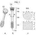
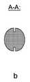
図1a、図1b、および図1cは、本発明の実施形態による骨ねじを示す。実施形態において、骨ねじは、ヘッド102を有するねじの切られたヘッド部分104ならびに、ネック区間106を有する隣接シャフト部分、中央区間108、およびねじの切られた前端110を含む(図1b)。実施形態において、ヘッド102は、様々なねじ駆動タイプ、例えばスロット付、フィリップス、六角形、ロバートソン、トルクス、その他を備え得る。実施形態において、骨ねじは、中心軸112を有する単一部品であり、その幾何学的形状は、回転対称であり得るか、または回転対称ではないことがあり得る。回転非対称である骨ねじの実施形態に対して、中央区間108および/またはネック区間106は、非円形断面、例えば短軸および長軸を有する楕円形または長方形の断面を有し得る(図1c)。したがって、骨ねじの曲げ剛性は、曲げる力が与えられる方向に依存し得る。実施形態において、最も低い曲げ剛性は、ねじシャフトをその短軸の周りで曲げることにより取得される。 1a, 1b and 1c show a bone screw according to an embodiment of the present invention. In an embodiment, the bone screw includes a threaded
図1および本明細書の他の図面は、比較的均一の断面を有するように見えるが、実施形態において、かかる骨ねじのシャフトの断面は、シャフトの長さに沿って比較的均一の断面を有し得るか、またはシャフトの長さに沿って変化する断面を有し得る。実施形態において、骨ねじのシャフトの一部分は、非円形断面を有し得、そして、そのシャフトの別の部分は、異なる非円形断面を有し得るか、または円形断面を有し得る。かかる骨ねじにおいては、適切な移行区間が、変化する断面2つの間でのまたは3つ以上の間での移行を提供する。 Although FIG. 1 and other drawings herein appear to have a relatively uniform cross section, in embodiments, the cross section of such a bone screw shaft has a relatively uniform cross section along the length of the shaft. It can have a cross section that varies along the length of the shaft. In embodiments, a portion of the shaft of the bone screw can have a non-circular cross-section and another portion of the shaft can have a different non-circular cross-section or can have a circular cross-section. In such bone screws, a suitable transition section provides a transition between two or three or more changing cross sections.
実施形態において、骨ねじのねじの切られた前端のねじ山は、中央区間が円形または非円形の断面にかかわらず、少なくとも部分的にねじの中央区間に沿って延び得る。中央区間が非円形断面を有する実施形態において、ねじ山は、ねじ山が円形の断面を維持するように、中央区間の全部または一部分に製造され得る。かかる実施形態において、中央区間のコア形状は、非円形断面を備え得、このようにして、方向依存の曲げ剛性を与え、一方、円形のねじ山は、遠くの皮質とのさらなる係合を可能にし得る。 In an embodiment, the threaded front thread of the bone screw may extend at least partially along the central section of the screw, regardless of whether the central section is circular or non-circular in cross section. In embodiments where the central section has a non-circular cross section, the threads may be manufactured on all or a portion of the central section such that the threads maintain a circular cross section. In such embodiments, the core shape of the central section may comprise a non-circular cross section, thus providing direction dependent bending stiffness, while the circular thread allows further engagement with distant cortex Can be.
図2a、図2b、および図2cは、骨ねじの実施形態を示す。実施形態において、骨ねじの曲げ剛性を低減する手段として、ねじの切られたヘッド部分204、ネック区間206、中央区間208、および/またはねじの切られた前端210は、1つ以上の長手方向のスロット214を有し得る(図2a)。本発明の目的により、用語「長手方向のスロット」は、配向が実質的に長手方向ではあるが、ねじの長手方向軸に対して平行であり得るか、または平行ではないことがあり得る、ねじシャフトのスロットを指す。実施形態において、スロット214は、ねじシャフト側面を部分的に(図2b)、または完全に(図2c)貫通し得る。実施形態において、所望の量の曲げ剛性は、適切なスロット深さ、スロット長さ、およびスロット構成を選択することによって達成され得る。 Figures 2a, 2b, and 2c show an embodiment of a bone screw. In an embodiment, the threaded
図3a、図3b、および図3cは、スロット314a、314b、および314cの様々な構成を示し、1つ以上の部分的にまたは完全に貫通するスロットは、骨ねじのねじを切られた前端310の中にもしくはこれを通って延び得るか(図3a)、または骨ねじのヘッド302の中にまたはこれを通って延び得る(図3b)。実施形態において、これらのねじ構成は、ねじの切られた前端310またはヘッド302のねじスロットが、ねじが遠い皮質、近い皮質、またはプレートの中に挿入される際に圧縮されるとしても、スロットの存在の結果として低減された曲げ剛性を有する。あるいは、実施形態において、1つ以上の部分的にまたは完全に貫通する長手方向のスロット314cは、少なくとも部分的にねじシャフトの周りで湾曲した方法で形成されて、曲げ剛性の複数方向での低減を達成し得る(図3c)。 FIGS. 3a, 3b, and 3c show various configurations of
実施形態において、図4は、非円形シャフト断面を有する骨ねじ400を示し、骨ねじ400は、ねじヘッド402がプレート416とポジティブロッキングするように骨折プレート416と関連している。実施形態において、完全に挿入された位置において、ねじシャフトの短直径は、長手方向のプレート軸418と位置合せされ得る。実施形態において、この回転位置合せは、ねじのねじ山420とプレート穴のねじ山422の両方を回転的に画定された、または調整された方法で製造することによって達成され得る。 In an embodiment, FIG. 4 shows a
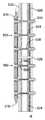
図5aおよび図5bは、6つのスロット付骨ねじ500を示し、6つのスロット付骨ねじ500は、骨折プレート516と関連し、模擬的な骨折空隙526を有する管状骨524に取り付けられている。図5aおよび図5bに6つのねじが示されているが、特定の用途次第で、例えば2つ、3つ、4つ、5つ、6つまたはこれを上回る任意の適切な数のねじが利用され得る。実施形態において、各骨ねじ500が、完全に挿入されたときに、各スロット514が、長手方向のプレート軸518に対して垂直に回転的に位置合せされることを保証するために、骨ねじ500は、調整された方法で、プレート516に固定され得る。実施形態において、各ねじのねじを切られた前端510は、遠い皮質528に固定され得、一方、軸方向かつ並進性の自由度は、近い皮質532におけるねじネック506と対応する穴530との間に残る。管状の骨524が軸方向に荷重を受けると、骨ねじ500は、最も低い曲げ剛性の方向に優先的に変形し得、それによって、骨折空隙526における圧縮変位が可能となる(図5b)。最も低い曲げ剛性を軸方向の荷重方向と合せることによって、骨プレートおよび骨ねじの適切な動きが生じることができ、これが治癒を助け、かつ骨に対する受容できないひずみを回避する。 FIGS. 5 a and 5 b show six slotted
様々な実施形態において、骨ねじの可撓性は、骨接合構造(ねじおよびプレート)の過度の荷重に対処するのに十分であり得る。かかる場合において、低い曲げ剛性は、制御された破損メカニズムを提供して、例えばプレートの曲げ破壊または骨破壊のようなより決定的な破損モードを遅らせるか、または防止する。さらに、実施形態において、この弾性は、ねじヘッド部分504の骨プレート516と係合する能力も向上させ得、特に、係合が、ねじヘッド部分504のねじ山を骨プレート516のねじが切られた通し穴522と係合させること含む実施形態に対して、および骨の穴と骨プレート516のねじが切られた通し穴522とが正確には同心的ではないとき、特にそうである。 In various embodiments, the flexibility of the bone screw may be sufficient to handle excessive loading of the osteosynthesis structure (screws and plates). In such cases, the low bending stiffness provides a controlled failure mechanism to delay or prevent more critical failure modes such as, for example, plate bending or bone failure. Further, in embodiments, this resilience may also improve the ability of the
実施形態において、ねじの切られた前端510は、セルフタッピング特徴を組み込み得、該セルフタッピング特徴は、ねじ山をタッピングする必要なく骨ねじ500の挿入を可能にする。さらに、実施形態において、ねじの切られた前端510は、セルフドリリング特徴も組み込み得、該セルフドリリング特徴は、皮質に穴を予めドリリングする必要なく、ねじ挿入を可能にする。さらに、実施形態において、ねじの切られた前端510は、中央区間508に向かって位置するセルフドリリング特徴も組み込み得、該セルフドリリング特徴は、近い皮質532のねじ穴(空洞)530の周辺において新たに形成された骨を貫通する、ねじの取り外し(引き抜き)を可能にする。かかる特徴は、2005年2月15に出願された米国特許出願公開第2006/0195099号に示され、該米国特許出願公開の全容は、本明細書に参考として援用されている。 In embodiments, the threaded
実施形態において、中央区間508には、短い高くなった切削フルートが提供され得、該短い高くなった切削フルートは、ねじの切られた前端510の外径と少なくとも同じ大きさであり、かつねじの切られた前端510の外径の2倍までであり得る直径を有する。このようにして、ねじの挿入の間、切削フルートは、近い皮質532のねじ穴530(最初に、ねじの切られた前端510が通り抜けることを可能にするために、より小さな直径で確立された)の直径をさらに拡大して、骨ねじ500のネック506が、近い皮質532に固く固定されないことを保証する。ねじの取り外し/引き抜きの間、切削フルートは、近い皮質532のねじ穴530を再び拡張して、新たに形成された骨を除去し得る。かかる特徴は、2005年2月15に出願された米国特許出願公開第2006/0195099号に示され、該米国特許出願公開の全容は、本明細書に参考として援用されている。 In an embodiment, the
図5aおよび図5bに示されるような実施形態において、複数のねじが適切な骨接合構造において利用され得るが、複数のねじは、同一である必要はない。実施形態において、骨折部位の近くに位置するねじは、骨折部位からさらに離れたねじとは異なる曲げ剛性を有し得る。さらに、実施形態において、骨接合構造の一組のねじのうちの1つ以上のねじは、回転非対称であり得、他は、回転対称であり得る。さらに、骨接合構造の一組のねじのうちの1つ以上のねじは、従来の単一皮質ねじまたは近い皮質と遠い皮質の両方において係合するポジティブロッキングねじ(両皮質ねじ)であり得る。 In embodiments as shown in FIGS. 5a and 5b, multiple screws may be utilized in a suitable osteosynthesis structure, but the multiple screws need not be the same. In embodiments, a screw located near the fracture site may have a different bending stiffness than a screw further away from the fracture site. Furthermore, in embodiments, one or more of the set of screws in the osteosynthesis structure can be rotationally asymmetric and the others can be rotationally symmetric. Further, one or more of the set of screws in the osteosynthesis structure can be a conventional single cortical screw or a positive locking screw (bicortical screw) that engages in both the near and far cortex.
実施形態において、遠い皮質ロッキングねじ(far−cortical loking screw)が、骨プレートの一端または両端において使用され得、一方、残りのねじは、従来の両皮質ロッキングねじおよび/または単一皮質ロッキングねじであり得る。実施形態において、荷重が骨プレートの端で最も高いことがあり得るので、プレートの一端または両端におけるFCLねじの使用は、最も外側のねじ穴による骨の破壊を防止し得る。 In embodiments, a far-cortical locking screw can be used at one or both ends of the bone plate, while the remaining screws are conventional bi-cortical locking screws and / or single cortical locking screws. possible. In embodiments, the load can be highest at the end of the bone plate, so the use of FCL screws at one or both ends of the plate can prevent bone destruction by the outermost screw holes.
前述は、管状の骨に対して使用されるとして示された骨ねじについて提示されたが、当業者は、本発明はそのように限定されず、非管状の骨に対しても実践され得ることを理解する。 Although the foregoing has been presented with respect to bone screws shown as being used for tubular bones, those skilled in the art will recognize that the invention is not so limited and may be practiced for non-tubular bones. To understand the.
図6は、ねじおよびプレート構造の軸方向の剛性を示し、スロット付ねじまたは非円形断面ねじの使用は、従来の(通常の)ねじに対して、構造剛性を24%および20%にそれぞれ低減した。これらの結果は、力学的構成の荷重変形挙動を数量化する有限要素解析(Finite Element Analysis)を使用して、ねじおよびプレート構造の演算モデル化から取得された。 FIG. 6 shows the axial stiffness of the screw and plate structure, and the use of slotted or non-circular cross-section screws reduces the structural stiffness to 24% and 20%, respectively, over conventional (normal) screws. did. These results were obtained from computational modeling of screw and plate structures using finite element analysis to quantify the load deformation behavior of the mechanical configuration.
このように、実施形態において、ポジティブロッキング回転非対称骨ねじの調整された(timed)適用、およびそれらを使用する方法は、1つ以上の利点を提供し得ることが、前述から分かり得る。実施形態において、回転非対称骨ねじは、固定構造の軸方向の剛性を低減して、骨折空隙における圧縮を可能にすることによって、骨折の治癒を促進する。実施形態において、回転非対称骨ねじは、ねじシャフト直径の回転対称低減を組み込む遠い皮質ロッキングねじと比較して、より高い剪断強度を保持する。実施形態において、回転非対称骨ねじは、固定構造を生み出し、該固定構造は、ねじシャフト直径の回転対称低減を有する遠い皮質ロッキングねじと比較してより高いねじり剛性の構造を提供する。実施形態において、回転非対称骨ねじは、ねじシャフトが、遠い皮質ロッキング適用の際に曲ると、ねじシャフトと管状の骨の近い皮質との間により大きな接触インターフェースを生み出す。 Thus, it can be seen from the foregoing that in embodiments, the timed application of positive locking rotationally asymmetric bone screws and methods of using them may provide one or more advantages. In embodiments, the rotationally asymmetric bone screw promotes fracture healing by reducing the axial stiffness of the fixation structure and allowing compression in the fracture gap. In embodiments, rotationally asymmetric bone screws retain higher shear strength compared to distant cortical locking screws that incorporate rotationally symmetric reduction of the screw shaft diameter. In an embodiment, a rotationally asymmetric bone screw creates a fixation structure that provides a higher torsional rigidity structure compared to a distant cortical locking screw having a rotationally symmetric reduction of the screw shaft diameter. In an embodiment, a rotationally asymmetric bone screw creates a larger contact interface between the screw shaft and the close cortex of the tubular bone when the screw shaft bends during distant cortical locking applications.
特定の実施形態が、好ましい実施形態の説明の目的のために、本明細書において例示、記述されたが、同じ目的を達成するように計算された広く様々な代替のおよび/または均等の実施形態もしくは実装が、本発明の範囲から逸脱することなく、図示され、かつ記述された実施形態に置換し得ることが当業者によって理解される。当業者は、本発明による実施形態は、非常に広く様々な方法で実装され得ることを容易に理解する。この適用は、本明細書に論議された実施形態の任意の適合または変形にまで及ぶことが意図されている。したがって、本発明による実施形態は、特許請求の範囲およびその均等物によってのみ限定されることが明白に意図されている。 While specific embodiments have been illustrated and described herein for the purpose of describing preferred embodiments, a wide variety of alternative and / or equivalent embodiments calculated to achieve the same purpose Alternatively, it will be appreciated by those skilled in the art that implementations may be substituted for the illustrated and described embodiments without departing from the scope of the invention. Those skilled in the art will readily appreciate that embodiments according to the present invention can be implemented in a very wide variety of ways. This application is intended to cover any adaptations or variations of the embodiments discussed herein. Therefore, it is manifestly intended that embodiments according to the present invention be limited only by the claims and the equivalents thereof.
Claims (25)
Translated fromJapaneseネック区間、中央区間、およびねじの切られた前端を有するシャフトであって、該ネック区間および該中央区間のうちの少なくとも1つは、回転非対称である、シャフトと、
該シャフトに隣接するねじの切られたヘッド部分であって、該ねじの切られたヘッド部分は、該骨プレートとの該骨ねじのポジティブロッキング係合を提供するねじ山を有する、ねじの切られたヘッド部分と
を備えている、骨ねじ。A bone screw for attaching the bone plate to the bone, the bone screw comprising:
A shaft having a neck section, a central section, and a threaded front end, wherein at least one of the neck section and the central section is rotationally asymmetric;
A threaded head portion adjacent to the shaft, the threaded head portion having a thread that provides positive locking engagement of the bone screw with the bone plate. A bone screw comprising:
骨プレートであって、骨ねじを該プレートに固定するためのロッキングねじ山を備えた2つ以上の穴を有する、骨プレートと、
該プレートとのポジティブロッキング係合のための2つ以上の骨ねじであって、該2つ以上の骨ねじのうちの少なくとも1つは、
ネック区間、中央区間、およびねじの切られた前端を有するシャフトであって、該ネック区間および該中央区間のうちの少なくとも1つは、回転非対称である、シャフトと、
該シャフトに隣接するねじの切られたヘッド部分であって、該ねじの切られたヘッド部分は、該骨プレートとの該骨ねじのポジティブロッキング係合を提供するねじ山を有する、ねじの切られたヘッド部分とを備えている、2つ以上の骨ねじと
を備えている、骨接合構造。An osteosynthesis structure,
A bone plate having two or more holes with locking threads for securing the bone screw to the plate;
Two or more bone screws for positive locking engagement with the plate, wherein at least one of the two or more bone screws is
A shaft having a neck section, a central section, and a threaded front end, wherein at least one of the neck section and the central section is rotationally asymmetric;
A threaded head portion adjacent to the shaft, the threaded head portion having a thread that provides positive locking engagement of the bone screw with the bone plate. An osteosynthesis structure comprising: two or more bone screws comprising:
Applications Claiming Priority (3)
| Application Number | Priority Date | Filing Date | Title |
|---|---|---|---|
| US11/672,300 | 2007-02-07 | ||
| US11/672,300US8398690B2 (en) | 2007-02-07 | 2007-02-07 | Rotationally asymmetric bone screw |
| PCT/US2007/085753WO2008097403A1 (en) | 2007-02-07 | 2007-11-28 | Rotationally asymmetric bone screw |
Publications (2)
| Publication Number | Publication Date |
|---|---|
| JP2010517673Atrue JP2010517673A (en) | 2010-05-27 |
| JP5465539B2 JP5465539B2 (en) | 2014-04-09 |
Family
ID=39539526
Family Applications (1)
| Application Number | Title | Priority Date | Filing Date |
|---|---|---|---|
| JP2009549071AExpired - Fee RelatedJP5465539B2 (en) | 2007-02-07 | 2007-11-28 | Rotational asymmetric bone screw |
Country Status (6)
| Country | Link |
|---|---|
| US (1) | US8398690B2 (en) |
| EP (1) | EP2114275B1 (en) |
| JP (1) | JP5465539B2 (en) |
| AU (1) | AU2007346619B2 (en) |
| CA (1) | CA2675375C (en) |
| WO (1) | WO2008097403A1 (en) |
Cited By (7)
| Publication number | Priority date | Publication date | Assignee | Title |
|---|---|---|---|---|
| JP2015526204A (en)* | 2012-08-23 | 2015-09-10 | シンセス・ゲーエムベーハーSynthes GmbH | Bone fixation system |
| JP2017094197A (en)* | 2011-03-03 | 2017-06-01 | ジンマー,インコーポレイティド | Bone screw with multiple thread profiles for far cortical locking and flexible engagement with bone |
| US9861406B2 (en) | 2012-08-23 | 2018-01-09 | DePuy Synthes Products, Inc. | Bone fixation system |
| US10004603B2 (en) | 2012-08-23 | 2018-06-26 | DePuy Synthes Products, Inc. | Bone implant |
| JP2021514686A (en)* | 2019-02-01 | 2021-06-17 | 北京愛康宜誠医療器材有限公司 | Meniscal replacement and knee prosthesis with it |
| JP2021514811A (en)* | 2018-02-27 | 2021-06-17 | アキュームド・エルエルシー | Bone fasteners with partially overlapping threads and changing leads |
| US11389216B2 (en) | 2009-03-24 | 2022-07-19 | Stabiliz Orthopaedics, LLC | Orthopedic fixation screw with bioresorbable layer |
Families Citing this family (36)
| Publication number | Priority date | Publication date | Assignee | Title |
|---|---|---|---|---|
| SE533303C2 (en) | 2007-07-24 | 2010-08-17 | Henrik Hansson | Device for fixing bone fragments in case of bone fracture |
| CA2702952C (en) | 2007-10-27 | 2017-01-03 | Parcus Medical, Llc | Suture anchor |
| US8114141B2 (en) | 2007-12-17 | 2012-02-14 | Synthes Usa, Llc | Dynamic bone fixation element and method of using the same |
| ES2533802T3 (en)* | 2008-09-02 | 2015-04-14 | Stryker Trauma Sa | Locator device for a bone plate |
| FR2941859B1 (en) | 2009-02-09 | 2012-04-06 | Memometal Technologies | OSTEOSYNTHESIS SCREW. |
| DE502009000626D1 (en)* | 2009-02-16 | 2011-06-16 | Stryker Trauma Ag | Bone screw and manufacturing method for this |
| US20100211113A1 (en) | 2009-02-17 | 2010-08-19 | Jon Olson | Bone Screw With Channels |
| US20130015613A1 (en)* | 2009-12-24 | 2013-01-17 | Mobius Protection Systems Ltd | Energy absorbing elements |
| EP2611376B1 (en)* | 2010-09-02 | 2016-08-31 | Neosteo | Osteosynthesis device |
| US8771324B2 (en) | 2011-05-27 | 2014-07-08 | Globus Medical, Inc. | Securing fasteners |
| JP6174111B2 (en) | 2012-03-13 | 2017-08-02 | シンセス・ゲーエムベーハーSynthes GmbH | Dynamic bone fixation element |
| EP2887896B1 (en) | 2012-08-23 | 2017-04-19 | Synthes GmbH | Bone implant |
| US9101426B2 (en)* | 2012-10-11 | 2015-08-11 | Stryker Trauma Sa | Cable plug |
| US20140214034A1 (en) | 2013-01-25 | 2014-07-31 | Fady Rayes | Cannulated telescopic femoral neck screw device and related fixation method |
| US9687284B2 (en) | 2013-02-13 | 2017-06-27 | Stryker European Holdings I, Llc | Locking peg with extended thread |
| US9949837B2 (en) | 2013-03-07 | 2018-04-24 | Howmedica Osteonics Corp. | Partially porous bone implant keel |
| ES2959525T3 (en)* | 2013-03-15 | 2024-02-26 | Paragon 28 Inc | intramedullary nail |
| EP2967535A4 (en) | 2013-03-15 | 2016-11-16 | Mark Brunsvold | Suture anchor |
| WO2014149015A2 (en)* | 2013-03-20 | 2014-09-25 | Parmaksizoğlu Ahmet Fatih | Locking plate-screw structure comprising a screw provided without threads on the screw head and locking directly into the screw hole disposed on the plate |
| US10499968B2 (en) | 2014-08-08 | 2019-12-10 | Stryker European Holdings I, Llc | Cable plugs for bone plates |
| US10478238B2 (en) | 2014-12-02 | 2019-11-19 | Activortho, Inc. | Active compression devices, methods of assembly and methods of use |
| CH710695B1 (en)* | 2015-02-03 | 2022-11-30 | Brianza Stefano | Device for variable fixation of bone fragments. |
| US10154863B2 (en) | 2015-07-13 | 2018-12-18 | IntraFuse, LLC | Flexible bone screw |
| US10485595B2 (en) | 2015-07-13 | 2019-11-26 | IntraFuse, LLC | Flexible bone screw |
| US10499960B2 (en) | 2015-07-13 | 2019-12-10 | IntraFuse, LLC | Method of bone fixation |
| US10492838B2 (en) | 2015-07-13 | 2019-12-03 | IntraFuse, LLC | Flexible bone implant |
| CN105342686B (en)* | 2015-12-15 | 2018-07-03 | 徐强 | Screw thread spicule |
| CA3015902A1 (en) | 2016-02-26 | 2017-08-31 | Activortho, Inc. | Active compression apparatus, methods of assembly and methods of use |
| US11224467B2 (en) | 2016-02-26 | 2022-01-18 | Activortho, Inc. | Active compression apparatus, methods of assembly and methods of use |
| JP6275798B1 (en)* | 2016-10-18 | 2018-02-07 | 株式会社シェルター | Bonded hardware |
| CN106725785B (en)* | 2016-12-24 | 2019-12-06 | 上海施必康医疗器械有限公司 | Internal fixation system for orthopedics department |
| US11147681B2 (en)* | 2017-09-05 | 2021-10-19 | ExsoMed Corporation | Small bone angled compression screw |
| US11191645B2 (en)* | 2017-09-05 | 2021-12-07 | ExsoMed Corporation | Small bone tapered compression screw |
| AT522112B1 (en)* | 2019-01-16 | 2021-01-15 | Surgebright Gmbh | Bone graft |
| AU2020291005A1 (en) | 2019-06-12 | 2022-01-20 | Government Of The United States Of America As Represented By The Department Of Veterans Affairs | Femoral head arthroplasty system |
| FR3120902B1 (en)* | 2021-03-18 | 2023-03-10 | Safran Aircraft Engines | CENTERING AND GUIDE DEVICE FOR AN AIRCRAFT TURBOMACHINE SHAFT |
Citations (6)
| Publication number | Priority date | Publication date | Assignee | Title |
|---|---|---|---|---|
| JPH06189991A (en)* | 1992-10-29 | 1994-07-12 | Medevelop Ab | Fixing tool to support prosthesis or joint mechanism for restored arthrosis |
| JP2002520114A (en)* | 1998-07-13 | 2002-07-09 | セピテク・ファウンデーション | Bone fastening screw |
| WO2004112587A2 (en)* | 2003-06-20 | 2004-12-29 | Acumed Llc | Bone plates with intraoperatively tapped apertures |
| US20060195099A1 (en)* | 2005-02-15 | 2006-08-31 | Apex Abc, Llc | Bone screw for positive locking but flexible engagement to a bone |
| WO2006105935A1 (en)* | 2005-04-04 | 2006-10-12 | Zimmer Gmbh | Pedicle screw |
| JP2006528895A (en)* | 2003-05-14 | 2006-12-28 | イニオン リミテッド | Soft tissue screw |
Family Cites Families (49)
| Publication number | Priority date | Publication date | Assignee | Title |
|---|---|---|---|---|
| FR742618A (en) | 1933-03-10 | |||
| US2654284A (en)* | 1951-05-23 | 1953-10-06 | Illinois Tool Works | Screw with self-drilling end |
| US3670724A (en)* | 1970-03-12 | 1972-06-20 | David N Bosacco | Prosthetic or fracture device and method |
| CH671150A5 (en)* | 1986-10-13 | 1989-08-15 | Jaquet Orthopedie | |
| MX170527B (en) | 1987-11-03 | 1993-08-30 | Synthes Ag | IMPLEMENTATION FOR OSTEOSYNTHESIS |
| EP0355035B1 (en) | 1987-11-03 | 1994-05-18 | SYNTHES AG, Chur | Bone plate with conical holes |
| US4959064A (en)* | 1988-10-07 | 1990-09-25 | Boehringer Mannheim Corporation | Dynamic tension bone screw |
| US5046905A (en)* | 1989-07-06 | 1991-09-10 | Emhart Inc. | Winged drill screw |
| JPH0716090Y2 (en)* | 1989-09-12 | 1995-04-12 | 山喜産業株式会社 | Tapping screw |
| US5382195A (en)* | 1992-12-22 | 1995-01-17 | Atlas Bolt & Screw Company | Method for making a self-drilling and self-tapping screw |
| CA2132832C (en)* | 1993-01-25 | 2001-08-14 | Synthes Ag | Lock washer for bone plate osteosynthesis |
| CA2189744C (en)* | 1995-03-27 | 2003-09-16 | Gilbert Talos | Bone plate |
| JP2000516493A (en)* | 1996-08-12 | 2000-12-12 | ジンテーズ アクチエンゲゼルシャフト クール | Bone fixation plate |
| US5954722A (en)* | 1997-07-29 | 1999-09-21 | Depuy Acromed, Inc. | Polyaxial locking plate |
| DE59710521D1 (en)* | 1997-10-20 | 2003-09-04 | Synthes Ag | BONE FIXATION DEVICE |
| US6019762A (en)* | 1998-04-30 | 2000-02-01 | Orthodyne, Inc. | Adjustable length orthopedic fixation device |
| US6129730A (en)* | 1999-02-10 | 2000-10-10 | Depuy Acromed, Inc. | Bi-fed offset pitch bone screw |
| US6712820B2 (en)* | 2000-02-01 | 2004-03-30 | Hand Innovations, Inc. | Fixation plate system for dorsal wrist fracture fixation |
| JP2002000611A (en)* | 2000-05-12 | 2002-01-08 | Sulzer Orthopedics Ltd | Bone screw to be joined with the bone plate |
| US6685473B2 (en)* | 2000-10-04 | 2004-02-03 | Bernard Weissman | Implants and modular components for assembly of dentures and bridges |
| US6306140B1 (en)* | 2001-01-17 | 2001-10-23 | Synthes (Usa) | Bone screw |
| US6558387B2 (en)* | 2001-01-30 | 2003-05-06 | Fastemetix, Llc | Porous interbody fusion device having integrated polyaxial locking interference screws |
| US20020156474A1 (en)* | 2001-04-20 | 2002-10-24 | Michael Wack | Polyaxial locking plate |
| US20040243128A1 (en)* | 2001-05-17 | 2004-12-02 | Howland Robert S. | Selective axis posterior lumbar spinal plating fixation apparatus and methods for use |
| DE10129490A1 (en)* | 2001-06-21 | 2003-01-02 | Helmut Mueckter | Implantable screw for stabilization of joint or bone fracture, has flexible shaft which interconnects proximal head portion and distal insertion portion of elongated screw body |
| US6736819B2 (en)* | 2001-10-18 | 2004-05-18 | Kishore Tipirneni | System and method for fixation of bone fractures |
| US6932606B2 (en)* | 2002-06-04 | 2005-08-23 | Zimmer Dental Inc. | Abutment screw with gold spring-washer |
| DE20209505U1 (en)* | 2002-06-19 | 2002-09-05 | Altenloh, Brinck & Co. GmbH & Co. KG, 58256 Ennepetal | Bolt-washer arrangement and its elements |
| JP2004044644A (en)* | 2002-07-10 | 2004-02-12 | Nippon Pop Rivets & Fasteners Ltd | Screw grommet |
| US20050101961A1 (en)* | 2003-11-12 | 2005-05-12 | Huebner Randall J. | Bone screws |
| US20050171544A1 (en)* | 2004-02-02 | 2005-08-04 | Acumed Llc | Bone plate with toothed aperture |
| FR2845588B1 (en)* | 2002-10-09 | 2006-12-15 | Biotech Internat | SELF-LOCKING OSTEOSYNTHESIS DEVICE |
| BRPI0408769A (en)* | 2003-03-26 | 2006-03-28 | Swiss Orthopedic Solutions Sa | lock bone plate |
| US7294130B2 (en)* | 2003-03-27 | 2007-11-13 | Depuy Products, Inc. | Distal radius fracture fixation plate having K-wire hole structured to fix a K-wire in one dimension relative to the plate |
| US20070016200A1 (en)* | 2003-04-09 | 2007-01-18 | Jackson Roger P | Dynamic stabilization medical implant assemblies and methods |
| US7951176B2 (en)* | 2003-05-30 | 2011-05-31 | Synthes Usa, Llc | Bone plate |
| US7135023B2 (en)* | 2003-07-07 | 2006-11-14 | Watkins William T | Compression bone screw device |
| US20050085818A1 (en)* | 2003-10-17 | 2005-04-21 | Huebner Randall J. | Systems for distal radius fixation |
| US8632570B2 (en)* | 2003-11-07 | 2014-01-21 | Biedermann Technologies Gmbh & Co. Kg | Stabilization device for bones comprising a spring element and manufacturing method for said spring element |
| US7637928B2 (en)* | 2004-01-26 | 2009-12-29 | Synthes Usa, Llc | Variable angle locked bone fixation system |
| US7833256B2 (en)* | 2004-04-16 | 2010-11-16 | Biedermann Motech Gmbh | Elastic element for the use in a stabilization device for bones and vertebrae and method for the manufacture of such elastic element |
| US7985222B2 (en)* | 2004-04-21 | 2011-07-26 | Medshape Solutions, Inc. | Osteosynthetic implants and methods of use and manufacture |
| US7175626B2 (en)* | 2004-06-15 | 2007-02-13 | Board Of Regents Of The University Of Nebraska | Dynamic compression device and driving tool |
| US7229445B2 (en)* | 2004-06-21 | 2007-06-12 | Synthes (Usa) | Bone plate with bladed portion |
| WO2006039412A2 (en)* | 2004-09-29 | 2006-04-13 | Trufast Corporation | Fastener having a removable drill tip and method |
| US20060173462A1 (en)* | 2005-01-28 | 2006-08-03 | Kay David B | Orthopedic screw for use in repairing small bones |
| US20080140076A1 (en)* | 2005-09-30 | 2008-06-12 | Jackson Roger P | Dynamic stabilization connecting member with slitted segment and surrounding external elastomer |
| DE202006000479U1 (en)* | 2006-01-12 | 2006-03-16 | Abc Verbindungstechnik Gmbh & Co. Kg | Self-piercing and thread-forming screw |
| US7850717B2 (en)* | 2006-03-01 | 2010-12-14 | Warsaw Orthopedic, Inc. | Bone anchors having two or more portions exhibiting different performance characteristics and method of forming the same |
- 2007
- 2007-02-07USUS11/672,300patent/US8398690B2/ennot_activeExpired - Fee Related
- 2007-11-28JPJP2009549071Apatent/JP5465539B2/ennot_activeExpired - Fee Related
- 2007-11-28EPEP07871613.1Apatent/EP2114275B1/ennot_activeNot-in-force
- 2007-11-28AUAU2007346619Apatent/AU2007346619B2/ennot_activeCeased
- 2007-11-28WOPCT/US2007/085753patent/WO2008097403A1/enactiveApplication Filing
- 2007-11-28CACA2675375Apatent/CA2675375C/ennot_activeExpired - Fee Related
Patent Citations (7)
| Publication number | Priority date | Publication date | Assignee | Title |
|---|---|---|---|---|
| JPH06189991A (en)* | 1992-10-29 | 1994-07-12 | Medevelop Ab | Fixing tool to support prosthesis or joint mechanism for restored arthrosis |
| JP2002520114A (en)* | 1998-07-13 | 2002-07-09 | セピテク・ファウンデーション | Bone fastening screw |
| JP2006528895A (en)* | 2003-05-14 | 2006-12-28 | イニオン リミテッド | Soft tissue screw |
| WO2004112587A2 (en)* | 2003-06-20 | 2004-12-29 | Acumed Llc | Bone plates with intraoperatively tapped apertures |
| US20060195099A1 (en)* | 2005-02-15 | 2006-08-31 | Apex Abc, Llc | Bone screw for positive locking but flexible engagement to a bone |
| WO2006105935A1 (en)* | 2005-04-04 | 2006-10-12 | Zimmer Gmbh | Pedicle screw |
| JP2008534096A (en)* | 2005-04-04 | 2008-08-28 | ツィンマー・ゲーエムベーハー | Pedicle screw |
Cited By (15)
| Publication number | Priority date | Publication date | Assignee | Title |
|---|---|---|---|---|
| US10918430B2 (en) | 2005-02-15 | 2021-02-16 | Zimmer, Inc. | Bone screw with multiple thread profiles for far cortical locking and flexible engagement to a bone |
| US11389216B2 (en) | 2009-03-24 | 2022-07-19 | Stabiliz Orthopaedics, LLC | Orthopedic fixation screw with bioresorbable layer |
| JP2017094197A (en)* | 2011-03-03 | 2017-06-01 | ジンマー,インコーポレイティド | Bone screw with multiple thread profiles for far cortical locking and flexible engagement with bone |
| US10772729B2 (en) | 2012-08-23 | 2020-09-15 | DePuy Synthes Products, Inc. | Bone implant |
| JP2018158174A (en)* | 2012-08-23 | 2018-10-11 | シンセス・ゲーエムベーハーSynthes GmbH | Bone fixation system |
| US10716606B2 (en) | 2012-08-23 | 2020-07-21 | DePuy Synthes Products, Inc. | Bone fixation system |
| JP2015526204A (en)* | 2012-08-23 | 2015-09-10 | シンセス・ゲーエムベーハーSynthes GmbH | Bone fixation system |
| US10004603B2 (en) | 2012-08-23 | 2018-06-26 | DePuy Synthes Products, Inc. | Bone implant |
| JP6991937B2 (en) | 2012-08-23 | 2022-01-13 | シンセス・ゲーエムベーハー | Bone fixation system |
| US9861406B2 (en) | 2012-08-23 | 2018-01-09 | DePuy Synthes Products, Inc. | Bone fixation system |
| JP2021514811A (en)* | 2018-02-27 | 2021-06-17 | アキュームド・エルエルシー | Bone fasteners with partially overlapping threads and changing leads |
| JP7358402B2 (en) | 2018-02-27 | 2023-10-10 | アキュームド・エルエルシー | Bone fasteners with partially overlapping threads and varying leads |
| JP2021514686A (en)* | 2019-02-01 | 2021-06-17 | 北京愛康宜誠医療器材有限公司 | Meniscal replacement and knee prosthesis with it |
| JP7015310B2 (en) | 2019-02-01 | 2022-02-02 | 北京愛康宜誠医療器材有限公司 | Meniscus alternative and knee prosthesis with it |
| US11364126B2 (en) | 2019-02-01 | 2022-06-21 | Beijing AK Medical Co., Ltd. | Meniscus substitute and knee joint prosthesis with meniscus substitute |
Also Published As
| Publication number | Publication date |
|---|---|
| CA2675375C (en) | 2015-02-10 |
| CA2675375A1 (en) | 2008-08-14 |
| US20080188899A1 (en) | 2008-08-07 |
| WO2008097403A1 (en) | 2008-08-14 |
| AU2007346619B2 (en) | 2011-04-14 |
| JP5465539B2 (en) | 2014-04-09 |
| AU2007346619A1 (en) | 2008-08-14 |
| US8398690B2 (en) | 2013-03-19 |
| EP2114275B1 (en) | 2017-05-31 |
| EP2114275A1 (en) | 2009-11-11 |
Similar Documents
| Publication | Publication Date | Title |
|---|---|---|
| JP5465539B2 (en) | Rotational asymmetric bone screw | |
| US8197523B2 (en) | Bone screw for positive locking but flexible engagement to a bone | |
| JP6392915B2 (en) | Bone screw with multi-thread profile fixed far-cortically and flexibly engaged to bone | |
| CA2647067C (en) | Bone stabilization system including multi-directional threaded fixation element | |
| JP6522866B1 (en) | Pedicle screw with large diameter bone screw | |
| EP2967582B1 (en) | Pedicle screw with reverse spiral cut | |
| JP5756118B2 (en) | Fixed support pin with variable angle | |
| JP2004329883A (en) | Bone fixation piece | |
| US20120253407A1 (en) | Bone fixture assembly | |
| US9814502B2 (en) | Bone plate and method of use | |
| CN104487010A (en) | Elongated pin for an external modular fixation system for temporary and/or permanent fixation applications and external modular fixation system | |
| CN114515187A (en) | Patella fracture hollow nail cable locking system | |
| EP2945555A1 (en) | Orthopedic plate | |
| CN215821129U (en) | A combined compression cannulated bone screw | |
| JP6553058B2 (en) | Elongated pin for external fixator application | |
| CN213156366U (en) | Dynamic locking screw and dynamic locking bone fracture plate system | |
| KR20190063078A (en) | Bending tool for medical bone joint plate and medical bone joint plate-bending kits |
Legal Events
| Date | Code | Title | Description |
|---|---|---|---|
| A621 | Written request for application examination | Free format text:JAPANESE INTERMEDIATE CODE: A621 Effective date:20101101 | |
| A521 | Request for written amendment filed | Free format text:JAPANESE INTERMEDIATE CODE: A523 Effective date:20111021 | |
| A131 | Notification of reasons for refusal | Free format text:JAPANESE INTERMEDIATE CODE: A131 Effective date:20120828 | |
| A977 | Report on retrieval | Free format text:JAPANESE INTERMEDIATE CODE: A971007 Effective date:20120830 | |
| A601 | Written request for extension of time | Free format text:JAPANESE INTERMEDIATE CODE: A601 Effective date:20121127 | |
| A602 | Written permission of extension of time | Free format text:JAPANESE INTERMEDIATE CODE: A602 Effective date:20121204 | |
| A521 | Request for written amendment filed | Free format text:JAPANESE INTERMEDIATE CODE: A523 Effective date:20121225 | |
| A131 | Notification of reasons for refusal | Free format text:JAPANESE INTERMEDIATE CODE: A131 Effective date:20130603 | |
| A521 | Request for written amendment filed | Free format text:JAPANESE INTERMEDIATE CODE: A523 Effective date:20130823 | |
| TRDD | Decision of grant or rejection written | ||
| A01 | Written decision to grant a patent or to grant a registration (utility model) | Free format text:JAPANESE INTERMEDIATE CODE: A01 Effective date:20140120 | |
| A61 | First payment of annual fees (during grant procedure) | Free format text:JAPANESE INTERMEDIATE CODE: A61 Effective date:20140122 | |
| R150 | Certificate of patent or registration of utility model | Ref document number:5465539 Country of ref document:JP Free format text:JAPANESE INTERMEDIATE CODE: R150 Free format text:JAPANESE INTERMEDIATE CODE: R150 | |
| R250 | Receipt of annual fees | Free format text:JAPANESE INTERMEDIATE CODE: R250 | |
| R250 | Receipt of annual fees | Free format text:JAPANESE INTERMEDIATE CODE: R250 | |
| R250 | Receipt of annual fees | Free format text:JAPANESE INTERMEDIATE CODE: R250 | |
| R250 | Receipt of annual fees | Free format text:JAPANESE INTERMEDIATE CODE: R250 | |
| LAPS | Cancellation because of no payment of annual fees |