JP2010515528A - Spinous process implants and related methods - Google Patents
Spinous process implants and related methodsDownload PDFInfo
- Publication number
- JP2010515528A JP2010515528AJP2009545544AJP2009545544AJP2010515528AJP 2010515528 AJP2010515528 AJP 2010515528AJP 2009545544 AJP2009545544 AJP 2009545544AJP 2009545544 AJP2009545544 AJP 2009545544AJP 2010515528 AJP2010515528 AJP 2010515528A
- Authority
- JP
- Japan
- Prior art keywords
- spacer
- extension
- implant
- spinous processes
- longitudinal axis
- Prior art date
- Legal status (The legal status is an assumption and is not a legal conclusion. Google has not performed a legal analysis and makes no representation as to the accuracy of the status listed.)
- Granted
Links
- 238000000034methodMethods0.000titleclaimsabstractdescription166
- 239000007943implantSubstances0.000titleclaimsabstractdescription148
- 230000008569processEffects0.000titleclaimsabstractdescription133
- 125000006850spacer groupChemical group0.000claimsabstractdescription191
- 239000000463materialSubstances0.000claimsdescription17
- 239000011148porous materialSubstances0.000claimsdescription14
- 230000001737promoting effectEffects0.000claimsdescription8
- 208000020307Spinal diseaseDiseases0.000claimsdescription7
- 230000008467tissue growthEffects0.000claimsdescription7
- 238000001356surgical procedureMethods0.000claimsdescription6
- 230000008859changeEffects0.000claimsdescription3
- 238000006073displacement reactionMethods0.000claimsdescription3
- 238000003780insertionMethods0.000claimsdescription3
- 230000037431insertionEffects0.000claimsdescription3
- 239000007779soft materialSubstances0.000claimsdescription3
- 238000013519translationMethods0.000claimsdescription3
- 239000000853adhesiveSubstances0.000claimsdescription2
- 230000001070adhesive effectEffects0.000claimsdescription2
- 230000007423decreaseEffects0.000claims2
- 238000004891communicationMethods0.000claims1
- 201000010099diseaseDiseases0.000abstractdescription4
- 208000037265diseases, disorders, signs and symptomsDiseases0.000abstractdescription4
- 210000000988bone and boneAnatomy0.000description23
- 230000008468bone growthEffects0.000description14
- 210000001519tissueAnatomy0.000description13
- 230000007246mechanismEffects0.000description9
- 238000013459approachMethods0.000description8
- 230000004927fusionEffects0.000description6
- 239000007787solidSubstances0.000description5
- 239000000126substanceSubstances0.000description5
- 210000002517zygapophyseal jointAnatomy0.000description5
- 230000008901benefitEffects0.000description4
- 230000000694effectsEffects0.000description4
- 229910052751metalInorganic materials0.000description4
- 239000002184metalSubstances0.000description4
- 210000000944nerve tissueAnatomy0.000description4
- 238000011065in-situ storageMethods0.000description3
- 210000003041ligamentAnatomy0.000description3
- 229920000642polymerPolymers0.000description3
- 241001325354LamiinaeSpecies0.000description2
- MCMNRKCIXSYSNV-UHFFFAOYSA-NZirconium dioxideChemical compoundO=[Zr]=OMCMNRKCIXSYSNV-UHFFFAOYSA-N0.000description2
- 229910045601alloyInorganic materials0.000description2
- 239000000956alloySubstances0.000description2
- 229910000389calcium phosphateInorganic materials0.000description2
- 239000001506calcium phosphateSubstances0.000description2
- 235000011010calcium phosphatesNutrition0.000description2
- 239000000919ceramicSubstances0.000description2
- 230000007850degenerationEffects0.000description2
- CGMRCMMOCQYHAD-UHFFFAOYSA-Jdicalcium hydroxide phosphateChemical compound[OH-].[Ca++].[Ca++].[O-]P([O-])([O-])=OCGMRCMMOCQYHAD-UHFFFAOYSA-J0.000description2
- 239000012530fluidSubstances0.000description2
- 238000012986modificationMethods0.000description2
- 230000004048modificationEffects0.000description2
- 108090000765processed proteins & peptidesProteins0.000description2
- 238000007788rougheningMethods0.000description2
- 210000004872soft tissueAnatomy0.000description2
- QORWJWZARLRLPR-UHFFFAOYSA-Htricalcium bis(phosphate)Chemical compound[Ca+2].[Ca+2].[Ca+2].[O-]P([O-])([O-])=O.[O-]P([O-])([O-])=OQORWJWZARLRLPR-UHFFFAOYSA-H0.000description2
- 238000009966trimmingMethods0.000description2
- WZBCCGZFIYLKIC-UHFFFAOYSA-NCC(CC1)CC1C1C=CC1Chemical compoundCC(CC1)CC1C1C=CC1WZBCCGZFIYLKIC-UHFFFAOYSA-N0.000description1
- OKTJSMMVPCPJKN-UHFFFAOYSA-NCarbonChemical compound[C]OKTJSMMVPCPJKN-UHFFFAOYSA-N0.000description1
- 102000014914Carrier ProteinsHuman genes0.000description1
- 206010016654FibrosisDiseases0.000description1
- 241000761557LaminaSpecies0.000description1
- 206010033799ParalysisDiseases0.000description1
- 102000010780Platelet-Derived Growth FactorHuman genes0.000description1
- 108010038512Platelet-Derived Growth FactorProteins0.000description1
- 239000004952PolyamideSubstances0.000description1
- 229920000954PolyglycolidePolymers0.000description1
- 239000004642PolyimideSubstances0.000description1
- RTAQQCXQSZGOHL-UHFFFAOYSA-NTitaniumChemical compound[Ti]RTAQQCXQSZGOHL-UHFFFAOYSA-N0.000description1
- HZEWFHLRYVTOIW-UHFFFAOYSA-N[Ti].[Ni]Chemical compound[Ti].[Ni]HZEWFHLRYVTOIW-UHFFFAOYSA-N0.000description1
- 230000009471actionEffects0.000description1
- PNEYBMLMFCGWSK-UHFFFAOYSA-Naluminium oxideInorganic materials[O-2].[O-2].[O-2].[Al+3].[Al+3]PNEYBMLMFCGWSK-UHFFFAOYSA-N0.000description1
- 210000003484anatomyAnatomy0.000description1
- 239000011324beadSubstances0.000description1
- 108091008324binding proteinsProteins0.000description1
- 239000000560biocompatible materialSubstances0.000description1
- 239000005312bioglassSubstances0.000description1
- -1boneChemical compound0.000description1
- 239000002639bone cementSubstances0.000description1
- 210000001185bone marrowAnatomy0.000description1
- 229910052799carbonInorganic materials0.000description1
- 238000005266castingMethods0.000description1
- 239000011248coating agentSubstances0.000description1
- 238000000576coating methodMethods0.000description1
- 230000006835compressionEffects0.000description1
- 238000007906compressionMethods0.000description1
- 238000012937correctionMethods0.000description1
- 230000006378damageEffects0.000description1
- 230000005786degenerative changesEffects0.000description1
- 238000009826distributionMethods0.000description1
- 239000000835fiberSubstances0.000description1
- 230000004761fibrosisEffects0.000description1
- 229920002313fluoropolymerPolymers0.000description1
- 239000004811fluoropolymerSubstances0.000description1
- 239000012634fragmentSubstances0.000description1
- 238000007499fusion processingMethods0.000description1
- 239000007952growth promoterSubstances0.000description1
- 238000002513implantationMethods0.000description1
- 238000001727in vivoMethods0.000description1
- 238000007373indentationMethods0.000description1
- 230000000266injurious effectEffects0.000description1
- 208000014674injuryDiseases0.000description1
- 238000002386leachingMethods0.000description1
- 210000004705lumbosacral regionAnatomy0.000description1
- 238000003754machiningMethods0.000description1
- 238000012423maintenanceMethods0.000description1
- 150000002739metalsChemical class0.000description1
- 239000000203mixtureSubstances0.000description1
- 229910001000nickel titaniumInorganic materials0.000description1
- 231100000862numbnessToxicity0.000description1
- 238000012856packingMethods0.000description1
- 239000002245particleSubstances0.000description1
- 239000004033plasticSubstances0.000description1
- 229920003023plasticPolymers0.000description1
- 229920000747poly(lactic acid)Polymers0.000description1
- 229920000058polyacrylatePolymers0.000description1
- 229920002647polyamidePolymers0.000description1
- 229920000728polyesterPolymers0.000description1
- 239000004633polyglycolic acidSubstances0.000description1
- 229920001721polyimidePolymers0.000description1
- 229920001470polyketonePolymers0.000description1
- 239000004626polylactic acidSubstances0.000description1
- 229920000098polyolefinPolymers0.000description1
- 238000003825pressingMethods0.000description1
- 102000004196processed proteins & peptidesHuman genes0.000description1
- 230000002035prolonged effectEffects0.000description1
- 102000004169proteins and genesHuman genes0.000description1
- 108090000623proteins and genesProteins0.000description1
- 238000011084recoveryMethods0.000description1
- 238000000926separation methodMethods0.000description1
- 238000005245sinteringMethods0.000description1
- 210000000278spinal cordAnatomy0.000description1
- 210000000273spinal nerve rootAnatomy0.000description1
- 208000005198spinal stenosisDiseases0.000description1
- 239000010935stainless steelSubstances0.000description1
- 229910001220stainless steelInorganic materials0.000description1
- 210000000130stem cellAnatomy0.000description1
- 229910052715tantalumInorganic materials0.000description1
- GUVRBAGPIYLISA-UHFFFAOYSA-Ntantalum atomChemical compound[Ta]GUVRBAGPIYLISA-UHFFFAOYSA-N0.000description1
- 230000008719thickeningEffects0.000description1
- 210000000115thoracic cavityAnatomy0.000description1
- 239000010936titaniumSubstances0.000description1
- 229910052719titaniumInorganic materials0.000description1
- 230000008733traumaEffects0.000description1
- 238000009941weavingMethods0.000description1
- 239000002759woven fabricSubstances0.000description1
Images


Classifications
- A—HUMAN NECESSITIES
- A61—MEDICAL OR VETERINARY SCIENCE; HYGIENE
- A61B—DIAGNOSIS; SURGERY; IDENTIFICATION
- A61B17/00—Surgical instruments, devices or methods
- A61B17/56—Surgical instruments or methods for treatment of bones or joints; Devices specially adapted therefor
- A61B17/58—Surgical instruments or methods for treatment of bones or joints; Devices specially adapted therefor for osteosynthesis, e.g. bone plates, screws or setting implements
- A61B17/68—Internal fixation devices, including fasteners and spinal fixators, even if a part thereof projects from the skin
- A61B17/70—Spinal positioners or stabilisers, e.g. stabilisers comprising fluid filler in an implant
- A61B17/7062—Devices acting on, attached to, or simulating the effect of, vertebral processes, vertebral facets or ribs ; Tools for such devices
- A61B17/7068—Devices comprising separate rigid parts, assembled in situ, to bear on each side of spinous processes; Tools therefor
- A—HUMAN NECESSITIES
- A61—MEDICAL OR VETERINARY SCIENCE; HYGIENE
- A61B—DIAGNOSIS; SURGERY; IDENTIFICATION
- A61B17/00—Surgical instruments, devices or methods
- A61B17/56—Surgical instruments or methods for treatment of bones or joints; Devices specially adapted therefor
- A61B17/58—Surgical instruments or methods for treatment of bones or joints; Devices specially adapted therefor for osteosynthesis, e.g. bone plates, screws or setting implements
- A61B17/68—Internal fixation devices, including fasteners and spinal fixators, even if a part thereof projects from the skin
- A61B17/70—Spinal positioners or stabilisers, e.g. stabilisers comprising fluid filler in an implant
- A61B17/7061—Spinal positioners or stabilisers, e.g. stabilisers comprising fluid filler in an implant for stabilising vertebrae or discs by improving the condition of their tissues, e.g. using implanted medication or fluid exchange
- A—HUMAN NECESSITIES
- A61—MEDICAL OR VETERINARY SCIENCE; HYGIENE
- A61B—DIAGNOSIS; SURGERY; IDENTIFICATION
- A61B17/00—Surgical instruments, devices or methods
- A61B17/56—Surgical instruments or methods for treatment of bones or joints; Devices specially adapted therefor
- A61B17/58—Surgical instruments or methods for treatment of bones or joints; Devices specially adapted therefor for osteosynthesis, e.g. bone plates, screws or setting implements
- A61B17/68—Internal fixation devices, including fasteners and spinal fixators, even if a part thereof projects from the skin
- A61B17/84—Fasteners therefor or fasteners being internal fixation devices
- A61B17/842—Flexible wires, bands or straps
- A—HUMAN NECESSITIES
- A61—MEDICAL OR VETERINARY SCIENCE; HYGIENE
- A61B—DIAGNOSIS; SURGERY; IDENTIFICATION
- A61B17/00—Surgical instruments, devices or methods
- A61B2017/00477—Coupling
Landscapes
- Health & Medical Sciences (AREA)
- Orthopedic Medicine & Surgery (AREA)
- Life Sciences & Earth Sciences (AREA)
- Surgery (AREA)
- Neurology (AREA)
- Heart & Thoracic Surgery (AREA)
- Engineering & Computer Science (AREA)
- Biomedical Technology (AREA)
- Nuclear Medicine, Radiotherapy & Molecular Imaging (AREA)
- Medical Informatics (AREA)
- Molecular Biology (AREA)
- Animal Behavior & Ethology (AREA)
- General Health & Medical Sciences (AREA)
- Public Health (AREA)
- Veterinary Medicine (AREA)
- Prostheses (AREA)
- Surgical Instruments (AREA)
Abstract
Translated fromJapaneseDescription
Translated fromJapanese本出願は、2007年4月17日に出願された米国特許仮出願第60/912,273号および2007年1月11日に出願された米国特許仮出願第60/884,581号の利益を主張する。 This application claims the benefit of US Provisional Application No. 60 / 912,273, filed April 17, 2007, and US Provisional Application No. 60 / 884,581, filed January 11, 2007. Insist.
[0001]本発明は棘突起インプラントおよび関連方法に関する。 [0001] The present invention relates to spinous process implants and related methods.
[0002]人間の脊柱の椎骨は、上下に次々と重ねて柱状に配列される。隣接椎骨間には、隣接椎骨間で力を伝達しかつそれらの間にクッションを提供する椎間板が存在する。椎間板は脊柱の屈曲および捩りを可能にする。年齢と共に椎間板の破壊または変性が始まり、結果的に椎間板の流体の損失が生じ、したがって結果的に椎間板の柔軟性が低下する。同様に、椎間板が薄くなり、椎骨を共に接近させる。変性の結果、椎間板の外層すなわち線維輪に断裂または亀裂が生じることもある。椎間板は外向きに膨隆し始めることがある。より重篤な事例では、椎間板の内部物質すなわち髄核が事実上、椎間板から外に押し出されるかもしれない。椎間板の変性変化に加えて、脊柱は自動車事故、転落、力仕事、および他の活動による外傷のため変化をきたすことがある。さらに、脊椎狭窄として知られるプロセスで、過度の骨成長、脊柱管内の(靭帯のような)組織の肥厚、または両方のため、脊柱管は狭窄する。これらの状態の全てにおいて、脊髄および脊髄神経根が通過する空間が狭められて、神経組織の圧迫を導くことがあり、それは身体の種々の部分の疼痛、しびれ感、脱力感、または麻痺さえも引き起こすことがあり得る。最後に、隣接椎骨間の椎間関節が変性し、限局痛および/または放散痛を引きこすことがある。上記状態の全てを集合的にここでは脊柱疾患と呼ぶ。 [0002] The vertebrae of the human spinal column are arranged in a columnar shape one above the other. Between adjacent vertebrae is an intervertebral disc that transmits force between adjacent vertebrae and provides a cushion between them. The intervertebral disc allows the spine to flex and twist. With age, disc destruction or degeneration begins, resulting in loss of disc fluid and, consequently, disc flexibility. Similarly, the intervertebral disc becomes thinner, bringing the vertebrae together. Degeneration can result in tears or cracks in the outer layer of the disc, or the annulus fibrosis. The intervertebral disc may begin to bulge outward. In more severe cases, the internal material of the disc, the nucleus pulposus, may be effectively pushed out of the disc. In addition to degenerative changes in the intervertebral disc, the spine can change due to trauma from car accidents, falls, hard work, and other activities. In addition, in a process known as spinal stenosis, the spinal canal becomes constricted due to excessive bone growth, thickening of tissue (such as ligaments) in the spinal canal, or both. In all of these conditions, the space through which the spinal cord and spinal nerve roots pass can be narrowed, leading to compression of nerve tissue, which can cause pain, numbness, weakness, or even paralysis in various parts of the body It can be caused. Finally, the facet joints between adjacent vertebrae can degenerate and cause localized and / or diffuse pain. All of the above conditions are collectively referred to herein as spinal disease.
[0003]従来、外科医は、隣接椎骨間の正常な間隔を回復しようと試みることによって脊柱疾患を治療している。これは、冒された神経組織から圧力を解放するのには充分であり得る。しかし、神経組織を侵害している椎間板物質、骨、または他の組織を外科的に除去し、かつ/または椎間関節を創傷清拭することもしばしば必要である。ほとんどの場合、椎骨間隔の回復は、骨、金属、またはプラスチックから作られた剛性スペーサを隣接椎骨間の椎間板空間内に挿入し、かつ椎骨を合体または融合させて単一の骨片にすることによって達成される。椎骨は一般的に、この融合プロセス中、隣接椎骨に固定された骨プレートおよび/またはペディクルスクリュを使用して安定化される。 [0003] Traditionally, surgeons treat spinal diseases by attempting to restore the normal spacing between adjacent vertebrae. This may be sufficient to relieve pressure from the affected nerve tissue. However, it is also often necessary to surgically remove disc material, bone, or other tissue that is injurious to nerve tissue and / or debride the facet joint. In most cases, vertebra spacing is restored by inserting a rigid spacer made of bone, metal, or plastic into the intervertebral disc space between adjacent vertebrae and coalescing or fusing the vertebrae into a single piece of bone. Achieved by: The vertebrae are typically stabilized during this fusion process using bone plates and / or pedicle screws that are secured to adjacent vertebrae.
[0004]椎間スペーサ、プレート、およびペディクルスクリュ固定システムを配置するための技術は近年、低侵襲性になってきたが、それらは依然として、脊柱に隣接する手術部位の深部にハードウェアを配置することが必要である。そのような外科手術からの回復は、数日の入院および正常な活動レベルまで長期の緩慢なリハビリテーションを必要とすることがあり得る。 [0004] Although techniques for placing intervertebral spacers, plates, and pedicle screw fixation systems have become less invasive in recent years, they still place hardware deep in the surgical site adjacent to the spinal column It is necessary to. Recovery from such a surgical procedure may require several days of hospitalization and prolonged slow rehabilitation to normal activity levels.
[0005]最近になって研究者らは、隣接椎骨が相互に対して動くことを可能にする可動性維持インプラントおよび技術の使用を促進してきた。わずかしか成功していない1つのそのようなインプラントとして、人工椎間板インプラントがある。これらは一般的に、椎間板空間に挿入される可撓性物質または2部品構成接合関節のいずれかを含む。別のそのようなインプラントとして、隣接椎骨の後方に延びる棘突起間に挿入され、脊柱が伸張するときに伸張停止体として働きかつ棘突起間の最小間隔を維持する、棘突起スペーサがある。棘突起スペーサは、脊柱が屈曲したときに隣接棘突起を離間させる。 [0005] More recently, researchers have promoted the use of mobile maintenance implants and techniques that allow adjacent vertebrae to move relative to each other. One such implant that has been marginally successful is an artificial disc implant. These generally include either a flexible material or a two-part joint joint that is inserted into the disc space. Another such implant is a spinous process spacer that is inserted between the spinous processes extending behind the adjacent vertebrae and serves as an extension stop and maintains a minimum spacing between the spinous processes as the spine extends. The spinous process spacer separates adjacent spinous processes when the spinal column is bent.
[0006]本発明は棘突起インプラントおよび関連方法を提供するものである。 [0006] The present invention provides spinous process implants and related methods.
[0007]本発明の一態様では、隣接椎骨の棘突起間に配置するためのインプラントは、スペーサおよび延長部を含む。スペーサは、その長手軸線と略平行な側壁であって棘突起と当接するように動作可能な上面および下面を有する側壁を有し、棘突起を離間関係に維持する。延長部はスペーサから長手軸線を横切るように突出し、隣接椎骨の棘突起と略平行に存在し、棘突起と係合して棘突起間の最大間隔を制限する。 [0007] In one aspect of the invention, an implant for placement between spinous processes of adjacent vertebrae includes a spacer and an extension. The spacer has a sidewall that is substantially parallel to its longitudinal axis and has upper and lower surfaces operable to abut the spinous process and maintains the spinous process in a spaced relationship. The extension projects from the spacer across the longitudinal axis and is substantially parallel to the spinous processes of adjacent vertebrae and engages the spinous processes to limit the maximum spacing between the spinous processes.
[0008]本発明の別の態様では、延長部は調節可能な固定具を含む。 [0008] In another aspect of the invention, the extension includes an adjustable fixture.
[0009]本発明の別の態様では、延長部は取り外し可能な固定具を含む。 [0009] In another aspect of the invention, the extension includes a removable fixture.
[0010]本発明の別の態様では、隣接椎骨の棘突起間に配置するためのインプラントは、組織の内方成長を促進するために、上外面および下外面の少なくとも1つから内向きに連通する少なくとも1つの横方向開口を有するスペーサを含む。 [0010] In another aspect of the invention, an implant for placement between spinous processes of adjacent vertebrae communicates inwardly from at least one of an upper outer surface and a lower outer surface to promote tissue ingrowth. A spacer having at least one lateral opening.
[0011]本発明の別の態様では、スペーサは、中空内部と、組織の成長を促進するために上面および下面から中空内部に連通する複数の横方向開口とを含む。 [0011] In another aspect of the invention, the spacer includes a hollow interior and a plurality of lateral openings that communicate from the top and bottom surfaces to the hollow interior to promote tissue growth.
[0012]本発明の別の態様では、スペーサは多孔質構造体を含み、横方向開口は複数の細孔を含む。 [0012] In another aspect of the invention, the spacer includes a porous structure and the lateral opening includes a plurality of pores.
[0013]本発明の別の態様では、脊柱の隣接椎骨の棘突起間に配置するためのインプラントは、スペーサおよびその両端でスペーサと係合可能な別々の延長部を含む。スペーサは種々の長さおよび上下面間の間隔で提供される。 [0013] In another aspect of the invention, an implant for placement between spinous processes of adjacent vertebrae of a spinal column includes a spacer and separate extensions that are engageable with the spacer at both ends thereof. Spacers are provided in various lengths and spacing between the top and bottom surfaces.
[0014]本発明の別の態様では、脊柱の隣接椎骨の棘突起間に配置するためのインプラントは、スペーサおよびセルクラージュ要素(cerclage element)を含む。セルクラージュ要素は使用中にスペーサが支点を画成するように正正中線より後方に偏位し、セルクラージュ要素は椎骨の一部分の周りに伸張可能であり、スペーサを中心とするモーメントを椎骨に与えるように作用する。 [0014] In another aspect of the invention, an implant for placement between spinous processes of adjacent vertebrae of a spinal column includes a spacer and a cerclage element. The cerclage element is displaced rearward from the midline so that the spacer defines a fulcrum in use, and the cerclage element is extendable around a portion of the vertebrae and exerts a moment about the spacer on the vertebrae. Acts to give.
[0015]本発明の別の態様では、インスツルメンテーションは、各々がハンドルに近ければ近いほど大きい断面寸法から自由端に近ければ近いほど小さくなる断面寸法までテーパを付けられた作業部を有する2つの器具を含む。器具の1つの自由端は、第1器具の自由端と係合する大きさおよびインプラントの中空先端と係合する大きさに作られた中空先端を画成する。 [0015] In another aspect of the invention, the instrumentation has a working portion that tapers from a larger cross-sectional dimension each closer to the handle to a smaller cross-sectional dimension closer to the free end. Includes two instruments. One free end of the instrument defines a hollow tip sized to engage the free end of the first instrument and to engage the hollow tip of the implant.
[0016]本発明の別の態様では、方法は、伸張停止体および屈曲停止体の両方をもたらすようにスペーサを隣接椎骨の棘突起の間に挿入するステップを含む。 [0016] In another aspect of the invention, the method includes inserting a spacer between the spinous processes of adjacent vertebrae to provide both an extension stop and a flexure stop.
[0017]本発明の別の態様では、方法は、スペーサを隣接椎骨の棘突起の間に挿入するステップ、およびスペーサを中心とするモーメントを椎骨に与えるようにセルクラージュ要素を隣接椎骨に接続するステップを含む。 [0017] In another aspect of the invention, the method includes inserting a spacer between the spinous processes of adjacent vertebrae, and connecting a cerclage element to the adjacent vertebrae to impart a moment about the spacer to the vertebrae. Including steps.
[0018]本発明の別の態様では、方法は、テーパ付き器具を隣接棘突起間に挿入するステップと、棘突起スペーサの先端をテーパ付き器具の先端に係合するステップと、係合された対を隣接棘突起間に戻してスペーサを棘突起間に挿入させるステップとを含む。 [0018] In another aspect of the invention, the method is engaged with inserting a tapered instrument between adjacent spinous processes and engaging the tip of the spinous process spacer with the tip of the tapered instrument. Returning the pair between adjacent spinous processes and inserting a spacer between the spinous processes.
[0019]本発明の種々の実施例について、添付の図面を参照しながら説明する。これらの図面は本発明の例証としての実施例を示すだけであり、本発明の範囲を限定するものと見なすべきではない。 [0019] Various embodiments of the invention will now be described with reference to the accompanying drawings. These drawings depict only exemplary embodiments of the invention and should not be considered as limiting the scope of the invention.
[0034]本発明に係る棘突起インプラントの実施形態は、スペーサと、スペーサから外向きに延びる延長部とを含む。棘突起インプラントは、頚椎、胸椎、および/または腰椎の隣接棘突起間に挿入するように構成することができる。スペーサは、患者間の解剖学的バリエーションおよび様々な程度の空間補正に適合するように種々のサイズを設けることができる。スペーサは、スペーサを椎体に固定させるために、棘突起からの組織の内方成長のような組織の内方成長を促進する開口を含むことができる。スペーサは、上下棘突起から組織が内方成長して隣接棘突起の融合が生じるように構成することができる。開口は比較的大きく、かつ/またはスペーサの中空内部と連通することができる。中空内部は、例えば物質を中空内部に詰め込むことによって、骨成長促進物質を受容するように構成することができる。開口は比較的小さく、かつ/またはスペーサ表面の少なくとも一部分に細孔または相互接続細孔を含むことができる。開口に骨成長促進物質を充填することができる。 [0034] An embodiment of a spinous process implant according to the present invention includes a spacer and an extension extending outwardly from the spacer. The spinous process implant can be configured to be inserted between adjacent spinous processes of the cervical, thoracic, and / or lumbar vertebrae. The spacer can be sized differently to accommodate anatomical variations between patients and varying degrees of spatial correction. The spacer can include an opening that promotes tissue ingrowth, such as tissue ingrowth from the spinous process, to secure the spacer to the vertebral body. The spacer can be configured such that tissue grows inwardly from the upper and lower spinous processes to cause fusion of adjacent spinous processes. The opening may be relatively large and / or communicate with the hollow interior of the spacer. The hollow interior can be configured to receive a bone growth promoting material, for example, by packing the material into the hollow interior. The openings are relatively small and / or can include pores or interconnecting pores in at least a portion of the spacer surface. The opening can be filled with a bone growth promoting substance.
[0035]スペーサは任意の適切な断面形状を有することができる。例えばそれは筒状、D字状、C字状、分離した片有しビームを含むH字状、および/または任意の他の適切な形状とすることができる。形状は面取り、隅肉、平坦部、リリーフカット、および/または例えばラミナおよび/または小面のような解剖学的特徴に適合する他の特徴を含むことができる。 [0035] The spacer can have any suitable cross-sectional shape. For example, it can be cylindrical, D-shaped, C-shaped, H-shaped with a separate stripped beam, and / or any other suitable shape. The shape can include chamfers, fillets, flats, relief cuts, and / or other features that conform to anatomical features such as lamina and / or facets.
[0036]延長部は、スペーサを隣接棘突起間に維持するようにスペーサからスペーサ長手軸線に対して横方向に延びることができる。単一延長部が1つ以上の方向に延びることができ、あるいは複数の方向に延びる複数の延長部を設けることができる。1つ以上の延長部は、延長部を棘突起に対して相対的に配置することができるように、相互にかつ/またはスペーサに対して長手方向に調整可能とすることができる。スペーサおよび別の延長部に対して相対的に軸線方向に移動可能な可動延長部を設けることができる。代替的に複数の可動延長部を設けることができる。例えば延長部は、棘突起を相互に対して不動化し、かつ隣接椎骨間の融合を促進するために、棘突起の側面に対してクランプすることができる。延長部は棘突起と係合可能な固定具を含むことができる。固定具は縫合糸、ワイヤ、ピン、ストラップ、クランプ、スパイク、ねじ、歯、接着剤、および/または他の適切な固定具を含むことができる。固定具は延長部に組み込むことができ、あるいはそれらはモジュール式とすることができる。モジュール式固定具は、強固な固定から無固定まで固定の種類および品質の個別調整が可能となるように、調整可能、交換可能、かつ/または取り外し可能とすることができる。スペーサ、延長部、および/または固定具は、異なる材料から作ることが有利であり得る。例えばスペーサおよび延長部は比較的軟質の材料から作られてもよく、固定具は比較的硬質の材料から作られてもよい。例えばスペーサおよび/または延長部はポリマおよび/または他の比較的軟質の材料から作られてもよく、固定具は金属および/または他の比較的硬質の材料から作られてもよい。 [0036] The extension can extend transversely to the spacer longitudinal axis from the spacer to maintain the spacer between adjacent spinous processes. A single extension can extend in one or more directions, or there can be multiple extensions extending in multiple directions. The one or more extensions can be adjustable relative to each other and / or relative to the spacer so that the extensions can be positioned relative to the spinous processes. A movable extension can be provided that is axially movable relative to the spacer and the other extension. Alternatively, a plurality of movable extensions can be provided. For example, the extension can be clamped against the sides of the spinous process to immobilize the spinous processes relative to each other and promote fusion between adjacent vertebrae. The extension can include a fastener that is engageable with the spinous process. Fixtures can include sutures, wires, pins, straps, clamps, spikes, screws, teeth, adhesives, and / or other suitable fasteners. The fasteners can be incorporated into the extension or they can be modular. Modular fixtures can be adjustable, replaceable, and / or removable to allow individual adjustments in the type and quality of fixation, from rigid fixation to no fixation. The spacers, extensions, and / or fixtures can be advantageously made from different materials. For example, the spacer and extension may be made from a relatively soft material and the fixture may be made from a relatively hard material. For example, the spacers and / or extensions may be made from polymers and / or other relatively soft materials, and the fixture may be made from metal and / or other relatively hard materials.
[0037]セルクラージュは棘突起インプラントを安定させるため、かつ/または他の利点をもたらすために使用することができる。例えばワイヤ、ストラップ、バンド、ケーブル、コード、および/または他の細長い部材が、椎弓根、ラミナ、棘突起、横突起、および/または他の脊柱構造を取り囲む。セルクラージュは脊柱の屈曲に堅固な抑制をもたらすように比較的非伸張性とすることができ、あるいはセルクラージュは屈曲に対する抵抗を高めるように比較的伸張性とすることができる。セルクラージュは織布のように比較的柔軟性およびドレープ性を有することができ、あるいはそれは金属帯のように比較的剛性とすることができる。セルクラージュは、移植後に事前設定形状を回復させる形状記憶特性を有することができる。セルクラージュは棘突起インプラントから独立することができ、あるいはそれと係合することができる。例えばセルクラージュは棘突起インプラントの中空内部を貫通し、かつ/または延長部と係合することができる。セルクラージュはスペーサから偏位させ、スペーサを支点として使用する緊張力を提供して、椎間板の荷重を除去しかつ/または椎間板空間を開くことができる。 [0037] Cerclage can be used to stabilize spinous process implants and / or provide other benefits. For example, wires, straps, bands, cables, cords, and / or other elongated members surround the pedicle, lamina, spinous process, transverse process, and / or other spinal structures. The cerclage can be relatively inextensible to provide a firm restraint in spinal flexion, or the cerclage can be relatively extensible to increase resistance to flexion. Cerclage can be relatively flexible and draped like a woven fabric, or it can be relatively rigid like a metal strip. The cerclage can have shape memory properties that restore the preset shape after implantation. The cerclage can be independent of, or engaged with, the spinous process implant. For example, the cerclage can penetrate the hollow interior of the spinous process implant and / or engage the extension. The cerclage can be displaced from the spacer and provide tension to use the spacer as a fulcrum to remove the disc load and / or open the disc space.
[0038]インプラントは、隣接椎骨の棘突起、ラミナ、横突起、小面、および/または他の脊柱構造の間の融合を促進する骨成長促進物質を補足することができる。骨成長促進物質はインプラントから離隔配置され、インプラントに隣接して配置され、インプラントと下にある骨との間に挟まれ、インプラント内部に配置され、インプラント上にコーティングされ、かつ/または他の仕方でインプラントに対して相対的に配置される。インプラント上にコーティングされる場合、インプラント全体をコーティングするか、またはインプラントの選択された部分だけを、例えば延長部、固定具、スペーサの棘突起接触部分、および/または他の部分をコーティングすることができる。 [0038] The implant can be supplemented with a bone growth promoting substance that promotes fusion between spinous processes, laminaes, transverse processes, facets, and / or other spinal structures of adjacent vertebrae. The bone growth promoting substance is spaced apart from the implant, placed adjacent to the implant, sandwiched between the implant and the underlying bone, placed inside the implant, coated on the implant, and / or otherwise In relation to the implant. When coated on the implant, the entire implant may be coated, or only selected portions of the implant may be coated, for example, extensions, fixtures, spinous process contact portions of spacers, and / or other portions. it can.
[0039]本明細書で使用する場合、骨成長促進物質は骨ペースト、骨小片、骨条片、構造骨移植片、血小板由来成長因子、骨髄液、幹細胞、骨成長タンパク質、骨成長ペプチド、骨結合タンパク質、骨結合ペプチド、ヒドロキシルアパタイト、リン酸カルシウム、および/または他の適切な骨成長促進物質を含むことができる。 [0039] As used herein, a bone growth promoting substance is bone paste, bone fragment, bone strip, structural bone graft, platelet-derived growth factor, bone marrow fluid, stem cell, bone growth protein, bone growth peptide, bone Binding proteins, bone binding peptides, hydroxylapatite, calcium phosphate, and / or other suitable bone growth promoting substances can be included.
[0040]インプラントおよびいずれかの関連セルクラージュまたは他の構成要素は、とりわけ金属、吸収性セラミック、非吸収性セラミック、吸収性ポリマ、および非吸収性ポリマをはじめとするいずれかの適切な生体適合性材料から作ることができる。幾つかの特定の例として、ステンレス鋼、チタンおよびニッケルチタン合金をはじめとするその合金、タンタル、ヒドロキシルアパタイト、リン酸カルシウム、骨、ジルコニア、アルミナ、炭素、バイオガラス、ポリエステル、ポリ乳酸、ポリグリコール酸、ポリオレフィン、ポリアミド、ポリイミド、ポリアクリレート、ポリケトン、フルオロポリマ、および/または他の適切な生体適合性材料、ならびにそれらの組合せが挙げられる。 [0040] The implant and any associated cerclage or other component may be any suitable biocompatible, including metals, resorbable ceramics, non-resorbable ceramics, resorbable polymers, and non-resorbable polymers, among others. Can be made from sex material. Some specific examples include stainless steel, titanium and nickel titanium alloys, including alloys thereof, tantalum, hydroxylapatite, calcium phosphate, bone, zirconia, alumina, carbon, bioglass, polyester, polylactic acid, polyglycolic acid, Polyolefins, polyamides, polyimides, polyacrylates, polyketones, fluoropolymers, and / or other suitable biocompatible materials, and combinations thereof.
[0041]棘突起インプラントは、棘上靭帯犠牲後方進入術、棘上靭帯温存後方進入術、側方進入術、および/または他の適切な手法をはじめ種々の外科的技法で脊柱疾患を治療するために使用することができる。棘突起インプラントは、隣接椎骨を融合することによって、または隣接椎骨間の運動を温存することによって、脊柱疾患を治療するために使用することができる。それはスペーサのような伸張停止体のみ、可撓性セルクラージュ要素のような屈曲停止体、または屈曲および伸張停止体の両方を含むことができる。棘突起インプラントは椎間関節に対する荷重を低減し、棘突起間隔を増加し、椎間板に対する荷重を低減し、前椎間板間隔を増加し、かつ/またはその他の方法で脊柱疾患を治療するために使用することができる。前方効果は、スペーサの後方の脊柱要素に張力を加えて棘状構造物に機械的利点を適用することによって達成することができる。棘突起インプラントのための技法は、手術部位の組織を改変せずにおくか、あるいはインプラント部位の組織をトリミング、やすり掛け、粗面化、および/または他の仕方で改変するなど、組織を改変することを含むことができる。 [0041] Spinous process implants treat spinal column disease with a variety of surgical techniques, including supraspinatric ligament sacrificial posterior approach, supraspinatric ligament-preserving posterior approach, lateral approach, and / or other suitable techniques Can be used for. Spinous process implants can be used to treat spinal column disease by fusing adjacent vertebrae or by preserving movement between adjacent vertebrae. It can include only stretch stops such as spacers, bend stops such as flexible cerclage elements, or both bend and stretch stops. Spinous process implants are used to reduce load on facet joints, increase spinous process spacing, reduce load on intervertebral discs, increase anterior disc spacing, and / or otherwise treat spinal disease be able to. The anterior effect can be achieved by applying a mechanical advantage to the spinous structure by applying tension to the spinal element behind the spacer. Techniques for spinous process implants modify the tissue, such as leaving the tissue at the surgical site unaltered, or trimming, sanding, roughening, and / or otherwise modifying the tissue at the implant site Can include.
[0042]図1および2は、腰椎10の1対の隣接椎骨の後方図および側面図を示す。上椎骨12は椎間板16によって下椎骨14から分離される。各椎骨は1対の横突起18、19、後方に突出する棘突起20、21、および横突起18、19を棘突起20、21に接続する1対のラミナ22、23を含む。椎間板16を介して接続されることに加えて、椎骨12、14は1対の椎間関節24で接合される。 [0042] FIGS. 1 and 2 show posterior and side views of a pair of adjacent vertebrae of the
[0043]図1〜9は例示的棘突起インプラント100を示す。インプラント100は、棘突起20、21間に配置されるスペーサ102を含む。スペーサ102の高さ104は、棘突起20、21をいかに緊密に連携して動かすことができるかを制限する。したがって、スペーサ102は棘突起20、21間の最小距離を維持する。隣接椎骨の後方沈下を伴う脊柱疾患の場合、棘突起20、21間のスペーサ102の挿入は、神経組織および椎間関節24から椎骨を離隔させ、それらに掛かる圧力を緩和する。 [0043] FIGS. 1-9 illustrate an exemplary
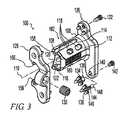
[0044]図3に示す通り、スペーサ102は、第1端106、第2端108、および第1端から第2端まで伸びる長手軸線110を含む。スペーサ102は、長手軸線110と略平行であり上および下外面114、116を含む側壁112を有する。横方向開口118(図6も参照)は、組織の内方成長を促進するために、上および下外面114、116から内方に連通する。例示的スペーサ102は、開口118が外面から中空内部120に連通するように、内面122で界接される中空内部120を含む。図1および2に、棘突起20間の骨成長による椎骨12、14の融合を促進するために中空内部120に詰め込まれた骨成長促進物質124が示される。 [0044] As shown in FIG. 3, the
[0045]棘突起インプラント100はさらに、上棘突起と略平行に位置するように長手軸線110に対して直角にスペーサ102から外向きに突出する、第1延長部126を含む。棘突起20に対する第1延長部126の当接は、スペーサ102を棘突起20間に維持するのに役立つ。例示的棘突起インプラント100では、第1延長部126はスペーサ102に対して固定され、インプラントは、第1延長部126に対して軸線方向に移動できるようにスペーサに取付け可能な第2延長部128を含む。第2延長部128は、棘突起20の幅に近づけるように、かつインプラント100をさらに安定させるように、第1延長部126に向かって移動することができる。それは、スペーサ102に対し止めねじ130を締め付けることによって適位置に固定される。延長部126、128は、棘突起20と係合してスペーサ102を棘突起20に固定させるために、棘突起に沿って延長部126、128から突出する固定具132、134、136を含む。図1は、棘突起20の側面に沿って骨成長を促進させて椎骨12、14の融合をさらに増強させるように、延長部126、128の間に挟まれた1片の骨125の形の追加的骨成長促進物質を示す。延長部126、128は(図示するように)下方に延びるだけでなく、場合により下棘突起に取り付けるように上方にも延びて、棘突起20を相互に不動化することが好ましい。 [0045] The
[0046]固定具132、134、および136は、任意の適切な形を取ることができる。それらは、例えば延長部と共に機械加工または鋳造することによって延長部126、128と一体化することができ、あるいは別々に形成して、延長部126、128に永久的に取り付けることができる。固定具132は延長部126と螺合する尖鋭スパイクである。螺合は固定具132を異なる固定具132と置換することを可能にする。例えば固定具132は、異なる形状、異なるサイズ、異なる材料、または異なる表面コーティングを有するものと置換することができる。螺合はまた、固定具132が延長部126から様々な量だけ延びるように調整し、それが骨とどの程度係合するかを変更することを可能にする。こうして固定具132は、様々な形状の骨に適合するように、または骨内に様々な量だけ侵入するように、調整することができる。湾曲または傾斜した骨に適合させるために、例えば複数のねじ付き固定具132を様々な量だけ延びるように調整することができる。最後に、非融合処置で屈曲を制限することなくインプラント100を伸張停止体として使用することを希望する場合のように、固定を希望しない場合に、螺合は使用者が固定具132を取り外すことを可能にする。 [0046]
[0047]固定具134および136は、複数のスパイクを迅速に調整、変更、または省略することを可能にするマルチスパイクポッドとして提供される。固定具134は、延長部126の非円形開口140と係合可能な非円形タブ138を含む。非円形係合は、固定具134の回転を防止する。タブ138は開口140とのプレス嵌め、スナップ嵌め、または他の適切な係合を形成することができる。タブ138は補足ねじ142によってさらに固定することができる。固定具136は、固定具136の長さを調整することができるようにベース部材146と螺合するねじ付き軸144を含む。固定具136を回転および角度調整して骨表面と係合することができるように、軸144は回動自在に延長部126と係合する。例示的実施形態では、軸144は、3自由度のボールソケット構成で開口140と係合する球形ボール148で終端する。しかし、任意の自由度数を可能にする任意の機構を使用することができる。延長部126が骨に向かって押圧されたときに固定具136が骨表面の角度に順応するように、固定具136は使用中に動くことができる。固定具136はまた、接合部の張力を調整し、かつ/または固定具136を所定の向きにロックするように、例えばねじ142によって固定することもできる。 [0047]
[0048]図4は、対向する延長部126、128における固定具の軸線関係を示す。例示的インプラント100では、インプラント100の頂部の固定具132は共通軸線150に沿って整列した状態で示される。インプラント100の底部の固定具134は、それらが骨内に押圧されるときに必要ならばインタリーブすることができるように、偏位した状態で示される。固定具の種類、個数、および位置合わせの任意の組合せをインプラント100に提供することができる。 [0048] FIG. 4 shows the axial relationship of the fixtures at the opposing extensions 126,128. In the
[0049]図5および6に示すように、スペーサ102の端部106、108は前側面取り152を含む。これらの面取り152は、端部106、108が椎間関節24のような椎骨12、14の後方に面する構造をうまく通過することを可能にする。また、図5および6に示す通り、スペーサ102の長手軸線110が延長部126、128の正中線154より前方に来るように、スペーサ102は延長部126、128に対して前側に偏位する。スペーサ102の前方偏位は、延長部126、128を棘突起20、21に沿わせながら、スペーサが棘突起20、21の間に深く嵌合することを可能にする。 [0049] As shown in FIGS. 5 and 6, the
[0050]図3および8に最も良く示す通り、第2延長部128は、スペーサ102の断面形状とほぼ合致するアパーチャ155を画成する。図1〜9の例示的実施形態では、アパーチャ155は前側に開口し、「C」字形を成す。タブ156はアパーチャの上部および下部から内方に延びて、スペーサ102の上面および下面の細長いスロット158と摺動自在に係合する。第2延長部128は、第1延長部126に近づけたり、そこから遠ざけるように長手方向に平行移動させることができる。スペーサ102の後面160に止めねじ130を締め付けることにより、タブ156はスロット158の側面に対して後方に押し付けられ、第2延長部128は適位置で長手方向にロックされる。スペーサ102の後面160は、図示する通り、止めねじ130をよりしっかりと握持するように粗面化することができる。止めねじ130は、スペーサ102を確実に握持するために、締付け時にスペーサ102の表面に食い込むこともできる。アパーチャ155をスペーサ102にぴったり一致させて、第2延長部128を第1延長部126に対して略平行な移動に制約することができる。代替的に、延長部128を下にある骨表面に順応させるために、図7に示すように第1延長部126に対する第2延長部128の所定の量の角度調整が可能となるように、アパーチャ155をスペーサ102より所定の量だけ大きくすることができる。 [0050] As best shown in FIGS. 3 and 8, the
[0051]図8に最も良く示す通り、第2延長部128は、第1ローブ中心線162を有する第1ローブ161と、第2ローブ中心線166を有する第2ローブ164とを含む。例示的実施形態では、第1ローブ中心線162および第2ローブ中心線166は平行であり、第2延長部128が略「Z」字状の平面形状を持つように離間する。この形状は、図9に示すように、マルチレベル外科手術において必要ならば1つのインプラント100の延長部が別のインプラント100とインタリーブさせて、インプラントを近接配置し、かつ/またはより広範囲の骨係合のために延長部ローブをより長くすることを可能にする。図1〜9の例示的実施形態では、中心線162および166は、第2延長部128の正中線154から等距離偏位する。中心線162および166は平行でなくてもよく、かつそれらは非対称に偏位して、様々な椎骨の解剖学的形態に適応するように様々な形状を成すことができる。例えば形状は脊柱10の様々な部分に合せて個別調整することができる。図1〜9の例示的実施形態では、第1延長部126は第2延長部128と同一形状を有する。しかし、形状は第1および第2延長部126、128の間で異なることができる。 As best shown in FIG. 8, the
[0052]図10は、スペーサ202と第1および第2延長部204、206とを有するインプラント200を示す。スペーサ202は組織をその中に成長させるための細孔208を含む。細孔208は相互に離間した個別開口、相互接続開口、または個別開口と相互接続開口の組合せとすることができる。スペーサ202は、全体にわたって均等な空隙率を有する一体ブロックとすることができる。代替的に、スペーサ202は異なる組成の外側多孔質層210および内側層212を含んでもよい。例えば、内側層212は中実、多孔質、中空、または他の構成とすることができる。多孔質の内側層は、外層210とは異なるサイズおよび/または分布の細孔を有してもよい。同様に、任意の多孔質部分は均一な空隙率、または細孔サイズまたは密度が変化する空隙率を有してもよい。種々の細孔構成が適切である。細孔サイズは1μmから2mmの範囲であることが好ましい。細孔サイズは1μmから500μmの範囲であることがより好ましい。細孔サイズは75μmから300μmの範囲であることがさらに好ましい。細孔は粒子の焼結;物質からの可溶性成分の浸出;繊維のマッティング、編織、または他の方法による結合;および/または他の公知のプロセスのような種々のプロセスによって生成することができる。細孔サイズは、硬組織成長、軟組織成長、または硬組織成長および軟組織成長の組合せを優先的に促進するように個別調整することができる。延長部204、206は中実であるかもしれず、あるいは延長部204、206内およびその付近での骨成長を助長するように、それらは大きい開口および/または小さい開口を有してもよい。スペーサ202および/または延長部204、206は、前述のようにコーティングすることもできる。 [0052] FIG. 10 shows an
[0053]延長部204、206は固定され、かつ/または調整可能とすることができる。図10の例示的インプラント200では、第1延長部204はスペーサ202の1端に固定され、第2延長部206は、延長部を棘突起に隣接して配置することができるように、スペーサ202に沿って平行移動可能である。図示された延長部204、206は、棘突起20、21と係合して棘突起20、21を相互に対して固定させることのできるスパイク214を場合により備えることが示されている。 [0053]
[0054]図10はまた、インプラント200に関連するセルクラージュの使用をも示す。例えば1つ以上の可撓性バンド216が、屈曲停止体をもたらすようにラミナ22、23の周りに配置される。バンド216は脊柱屈曲中にスパイク214に掛かる荷重を担持するのに役立つ。バンド216とは代替的に、またはそれに加えて、1つ以上のバンド218、220を横突起18、19の周りに配置することができる。 [0054] FIG. 10 also illustrates the use of cerclage in connection with the
[0055]図11〜13は、本発明に係る棘突起インプラント300に関連するセルクラージュの使用の追加実施例を示す。インプラントは、隣接棘突起20、21間に配置するためのスペーサ302と延長部304とを含む。図11の実施例では、可撓性材料のバンド310は棘突起20、21の周りにループされる。棘突起がスペーサ302と接触する領域312、314の後ろにバンド310を配置することによって、オフセット318が形成される。バンド310を締め付けることにより、各椎骨12、14にモーメント320、322が発生し、隣接椎骨12、14間の椎間板16に対する圧力の一部が除去される。バンド310の締付けを増大することにより、椎骨12、14の前方の間隔324が事実上増大することがある。こうして、棘突起インプラント300をバンド310と組み合わせて使用することにより、インプラント300を支点として使用して、椎骨12、14をてこ作用で離間させることができる。既述の利点に加えて、この組合せは、典型的な椎間板離間処置より侵襲性の低い後部棘突起処置により、前方椎間板空間効果を生じる。 [0055] FIGS. 11-13 illustrate additional examples of the use of cerclage in connection with the
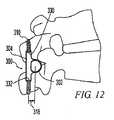
[0056]図12および13の実施例では、インプラント300は、セルクラージュバンド310をインプラント300に取り付けるための機構を含む。図12の実施例では、機構は延長部304の上端および下端に開口330、332を含む。バンド310を延長部304に取り付けることによって、バンド310および延長部304は、前後方向に変位しないように相互に安定化するのに役立つ。この取付けは、バンド310をスペーサ302から所定の偏位318で配置するのにも役立つ。図13の実施例では、バンド310はスペーサ302自体の中空内部にループされる。この実施例では、バンドは偏位せず、椎骨に対して生じるモーメントは最小限または零である。 [0056] In the example of FIGS. 12 and 13, the
[0057]図14〜24は、可動延長部を図1のインプラントに取り付けるための代替的機構を示す。図14を参照すると、インプラント400はスペーサ402、第1延長部404、および第2可動延長部406を含む。可動延長部406は、リングがスペーサ402上に摺動自在に受容可能であるように、スペーサ402の外面とほぼ合致する内面410を持つリング408の形の本体を含む。可動延長部406をスペーサ402上の所望の位置に固定するために、スペーサ402に対して止めねじ412が締め付けられる。止めねじ412を締め付けることにより、可動延長部406はスペーサ402に対して後方に偏倚する。リングの前部414はこの後方偏倚に対抗してスペーサ402の前部416を押圧し、止めねじ412が延長部406をロックすることを可能にする。スペーサ402は、所定の軸線方向位置で止めねじ412と確実に係合するように、複数の圧痕418を含むことができる。リング408は、スペーサ402に対する延長部406の所定の量の傾斜が可能になる大きさにすることができる。 [0057] FIGS. 14-24 show an alternative mechanism for attaching the movable extension to the implant of FIG. Referring to FIG. 14, the
[0058]図15を参照すると、インプラント500はスペーサ502、第1延長部504、および第2可動延長部506を含む。スペーサ502は、長手軸線512と平行に第1延長部504から離れるように突出する複数の片有しビーム508、510を含む。図15の実施例では、スペーサ502は、凹面が内側に向けられた1対の対向する「C」字状ビーム508、510を含む。スペーサ502はビーム508、510を貫通する開口514を含み、かつ前方および後方にビーム間の細長い開口516、518を画成する。可動延長部506は不連続リング520の形の本体を含む。リング520は前方に開口し、開口の辺縁は後ろ向きのフック522、524を画成する。リングをスペーサ502上に摺動自在に受容できるように、リングの内面526はビーム508、510の外面とほぼ合致する。リング520の開放前側構成は、リングをインビボで容易に摺動できるようにクリアランスを提供する。可動延長部506をスペーサ上の所望の長手方向位置に固定するために、止めねじ528がスペーサ502に対して締め付けられる。フック522、524は、止めねじ528が締め付けられるときに、スペーサ502に対するリングの後方の平行移動に抵抗するために、ビーム508、510の前縁の一部分に沿って湾曲する。 [0058] Referring to FIG. 15, the
[0059]図16を参照すると、スペーサ602、第1延長部604、および可動延長部606を有する、図15のインプラント500と同様のインプラント600が示されている。しかし、リング608は、図15のリング520よりずっと大きい前側クリアランスを設けるように前側が切り取られている。リング608は、スペーサ602に対するリングの後方の平行移動に抵抗するためにビーム614、616の内面612と係合するように、リング608の後面から前方に突出しかつ上方および下方に延びるキー610を含む。キー610はまた、場合により内部618に詰め込まれた物質を保持するのを助けるように、スペーサ602の中空内部618を部分的に塞ぐ。 [0059] Referring to FIG. 16, an
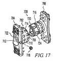
[0060]図17を参照すると、インプラント700はスペーサ702、第1延長部704、および第2可動延長部706を含む。スペーサ702は外面710および内面712を画成する側壁708を含む。図17の実施例では、スペーサ702は、断面が略「D」字状の中空扁平筒形である。しかし、スペーサ702は任意の所望の形状とすることができる。スペーサ702は外面710から内面712に連通する複数の開口714を含む。可動延長部706は、スペーサ702とほぼ同様の形状であるが、スペーサ702内で伸縮自在な関係に摺動する大きさに作られた突出部716を含む。突出部(またはスペーサ)は場合により、延長部704、706を所望の長手方向の間隔にロックする1つ以上の固定機構を含むことができる。固定機構は止めねじ718、溝722または他の特徴とのスナップ嵌めを形成する隆条720、開口714と係合可能な戻り止め724、および/または他の適切な固定機構を含むことができる。これらの機構のいずれか1つまたは組合せを使用することができ、それらは図示する向きと逆転させることができる。 [0060] Referring to FIG. 17, the
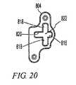
[0061]図18〜20を参照すると、インプラント800はスペーサ802、第1延長部804、および第2可動延長部806を含む。スペーサ802は、この実施例では3つのビーム808、810、812が存在することを除き、図15および16と同様の複数の片有しビームを含む。ビームは長手軸線814と平行に、第1延長部804から遠ざかるように突出する。図18の実施例では、前ビーム812は後方に開口した溝816を含む。後ビーム808、810および前ビーム812はそれらの間に、上方および下方に開口した細長いスロット818を画成する。後ビーム808、810はさらにそれらの間に、後方に開口した細長いスロット820を画成する。図20は、第1延長部804を貫通して突出する溝816およびスロット818、820の突出によって画成される十字形開口822を示す。可動延長部806は、スロット818と摺動自在に係合する大きさに作られた本体824を含む。第1延長部804に対する可動延長部806の傾斜を抑止するために、場合により突耳826が前方に溝816内に突出することができる。突耳826は、可動延長部806の傾斜を防止するために溝816内に密嵌する大きさにすることができ、あるいは所定の量の傾斜が可能であるように、溝816より小さい大きさにすることができる。可動延長部806をスペーサ802にロックするために、止めねじ828が設けられる。 [0061] Referring to FIGS. 18-20, the
[0062]図21を参照すると、図16のインプラントとほぼ同様に構成されたインプラント900が図示されている。しかし、第1延長部904に隣接する端壁902は貫通穴906を含み、可動延長部908は貫通穴912を持つキー910を含む。穴906、912は、延長部904、908が離れるのを防止するためにそれらを最大間隔に固定する固定具を受容する。固定具はねじ、ボルト、ナット、ケーブル、ワイヤ、ひも、ロッド、および/または任意の他の適切な固定具を含むことができる。図21の実施例では、固定具は、ケーブルのような細長いクリンプ受容部材914、およびフェルールまたは圧縮性ビードのようなクリンプ部材916、918を含む。 [0062] Referring to FIG. 21, illustrated is an
[0063]図22を参照すると、インプラント1000はスペーサ1002、第1延長部1004、および第2延長部1006を含む。スペーサ1002は、外面1008に沿ってかつ第1延長部1004を貫通して延びる1つ以上の長手方向の溝1010を画成する外面1008を含む。第1延長部1004は、第1延長部1004を貫通して半径方向に外向きに延びかつ溝1010と連通する部分1014を有する、1つ以上の対応するスロット1012を含む。スロット1012は、半径方向に内向きに延びて溝1010の端にショルダ1018を画成する部分1016を有する。第2延長部1006は、第1延長部1004に向かって長手方向に突出して半径方向内向きのタブ1022で終端する、1つ以上の対応する突出部1020を含む。第2延長部1006はさらに、スペーサ1002の円錐形自由端1026と係合可能な円錐形開口を有する調心穴1024を含む。第2延長部1006は、タブ1022が溝1010に係合するまで突出部を外向きに広げるようにタブ1022をスペーサ1002の円錐形端部1026に押し付けることによって、スペーサ1002に取り付けられる。タブ1022はスロット1012から抜け出るまで溝1010に沿って摺動し、タブ1022はショルダ1018を越えて部分1016内に内向きにスナップ嵌合する。タブ1022がショルダ1018に当接することにより、第1および第2延長部1004、1006が離れるように移動する防止される。スペーサ1002の円錐形端部1026と穴1024との係合は、組立体に半径方向の安定性をもたらす。 [0063] Referring to FIG. 22,
[0064]図23を参照すると、インプラント1100はスペーサ1102、第1延長部1104、および第2延長部1106を含む。スペーサ1102は横溝1108と、拡大ヘッド1112を有する中央ボス1110とを含む。第2延長部1106は、溝1108内に嵌合する大きさに作られた部分1114と、1つ以上の傾斜タブ1118が境界を定める開口1116とを含む。第2延長部1112は、中央ボス1110を開口1116内に方向付けて、部分1114を溝1108内に押し込むことによってスペーサに組み付けられる。ボス1110は開口1116に押し込まれ、それを通過させるためにタブ1118は外向きに屈曲する。ひとたびボス1110がタブ1118を通過すると、タブ1118は元の位置に戻り、拡大ヘッド1112の後部にスナップ嵌合する。この構成では、ボス1110が第2延長部1106を長手方向に保持し、溝1108は第2延長部1106がインプラント1100の長手軸線を中心に回転することを防止する。 [0064] Referring to FIG. 23,
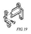
[0065]図24を参照すると、インプラント1200はスペーサ1202、第1延長部1204、および第2延長部1206を含む。スペーサ1202は、中空内部1210を画成する中実筒状側壁1208を含む。延長部1204、1206は同様に構成され、各々が、スペーサ1202の内側に嵌合する大きさに作られた突出部1212、1214を含む。延長部1204、1206は、プレス嵌め、スナップ嵌め、ねじ込み、および/またはそれ以外の方法で部分1212、1214をスペーサ1202と係合することによって、スペーサに取り付けることができる。代替的に、または追加的に、延長部1204、1206は、図3に示した止めねじまたは図21に示した細長い固定具のような前掲の取り付け機構のいずれかにより、スペーサ1202に取り付けることができる。図24の実施例では、延長部1204、1206は、スペーサ1202内に押し込む可撓性花弁状片1216を形成するように、長手方向に切込みが付けられる。延長部1204、1206は、組織成長を可能にし、セルクラージュ部材の取付けを許容し、かつ/または棘突起に取り付けられる追加固定具を受容する開口1218を含む。 [0065] Referring to FIG. 24, the
[0066]図24のスペーサ1202は、他の実施例の幾つかで図示するように開口を有することができる。同様に、他の実施例は、図24に示すように中実表面を有することができる。同様に、任意の実施例の延長部は中実とするか、開口を有するか、またはその他の好都合な形に構成することができる。 [0066] The
[0067]本発明に係るインプラントは、種々の外科的手法および技法を用いて移植することができる。外科的手法は、棘上靭帯犠牲後方進入術、棘上靭帯温存後方進入術、側方進入術、および/または他の適切な手法を含むことができる。技法は、手術部位の組織を改変せずにおくか、あるいはそれらをトリミング、やすり掛け、粗面化、もしくは他の仕方で改変するなど、組織を改変することを含むことができる。例えば図1では、側方進入術が使用され、下棘突起は、インプラント100を受容するために棘間空間を拡大するように、その上面26が切断される。棘間空間が用意された後、スペーサ102が棘間空間内に挿入される。第1延長部126が存在する場合、それは1つ以上の棘突起付近に位置するかまたは当接するように、内方に押し込むことができる。第2延長部128が使用される場合、それはスペーサ102と係合し、場合により同じく内方に押し込まれる。図1では、内向きの骨固定具を有する対向延長部126、128が使用され、固定具132が棘突起20、21と係合するように内向きに押圧される。延長部は図3、8、および9に示すように上方および下方に偏位するので、固定具132と下棘突起21の係合は図1には示されない。 [0067] Implants according to the present invention can be implanted using a variety of surgical techniques and techniques. Surgical procedures may include supraspinatric ligament sacrificial posterior approach, supraspinous ligament-preserving posterior approach, lateral approach, and / or other suitable procedures. The technique can include modifying the tissue, such as leaving the tissue at the surgical site unaltered or trimming, sanding, roughening, or otherwise modifying them. For example, in FIG. 1, a lateral approach is used and the lower spinous process has its upper surface 26 cut to enlarge the interspinous space to receive the
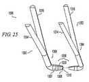
[0068]図25および26を参照すると、棘間空間へのインプラントの側方挿入を容易化するために1組の器具1300が提供される。器具の組は複数の挿入器1302、1303を含み、各挿入器1302、1303は第1部分すなわちハンドル部1304および第2部分すなわち作業部1306を有する。作業部1306は棘間空間に挿入可能である。好ましくは、ハンドル部1304は、作業部1306が棘間空間にあるときに挿入器1302、1303の保持および操作を容易化するように、作業部1306に対して直角に延びる。ハンドル部1304および作業部1306は、湾曲、角度、変位、および/または任意の他の適切な直交配向を画成することができる。図25の実施例では、挿入器1302、1303は略「L」字状である。作業部1306は、その自由端1308から離間した第1部分1307における比較的大きい断面寸法からその自由端1308における比較的小さい断面寸法までテーパを付けられる。例示的実施形態では、作業部は円錐形であり、より大きい径からより小さい径までテーパを付けられる。端部1308は開口1310を有する中空先端を画成する。器具1300の組には、1つの挿入器1302の端部1308が別の挿入器1303の先端の開口1310の内部に嵌合するように、様々な大きさの作業部1306を有する複数の同様に構成された挿入器が設けられる。場合により作業部1306は、対向ハンドル1314、1316に取り付けられた対向半体に分離することができる。対向ハンドル1314、1316が相互に対して移動すると、作業部1306の対向半体は相互に対して移動する。例示的実施形態では、ハンドル1314、1316を相互に向かって圧搾すると、作業部1306の対向半体は外向きに開いて相互に離れるので、作業部1306は展開する。 [0068] Referring to FIGS. 25 and 26, a set of
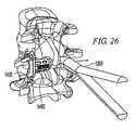
[0069]使用中に、第1挿入器1302は棘間空間内に挿入される。第1挿入器1302は容易に挿入されるように比較的小さい。端部1308がさらに挿入されると、テーパ付き作業部1306は棘間空間を拡張させる。場合により、作業部が棘間空間内部にあるときに、例えばハンドル1314、1316を圧搾するなど、作業部を展開させることによって、棘間空間をさらに拡張させることができる。第1挿入器1303を取り外し、第2挿入器1302を挿入するために、第2のより大きい挿入器1302の中空先端を第1挿入器1303の先端上に配置し、次いで重なり合った器具を棘間空間内に戻すことによって、第2挿入器1302が第1挿入器1303と係合される。第2挿入器1303の端部がさらに挿入されると、テーパ付き作業部は棘間空間を拡張させる。場合により、作業部が棘間空間内部にあるときに、作業部を展開させることによって、棘間空間をさらに拡張させることができる。このようにして、棘間空間が所望のサイズに拡張されるまで、徐々に大きい挿入器を挿入することができる。ひとたび所望のサイズに達すると、最後の挿入器のサイズを手掛かりにすることによって、適切なインプラントサイズを決定することができる。インプラントの大きさの決定をさらに容易化するために、挿入器は場合により、様々なスペーササイズに対応する印1320をテーパ付き作業端に付けることができる。インプラントは、図26に示すように、スペーサ1402を挿入器の作業端に係合することによって挿入される。インプラントを挿入器の中空先端の内部に係合させることができ、あるいは図示するように挿入器の先端をインプラントの中空先端に係合させることができる。挿入器が引き出されるときに、スペーサ1402は棘間空間内に押し込まれる。 [0069] In use, the
[0070]棘突起インプラントならびに関連する器具および技術の実施例を詳細に説明しかつ図示したが、それは単なる例証および実施例として意図されたものであって、限定と受け止めるべきではないことを理解されたい。したがって棘突起インプラント、器具、および技術の変形および修正は当業者に明白になる。以下の特許請求の範囲は全てのそのような修正および均等物を網羅することが意図される。 [0070] While examples of spinous process implants and related instruments and techniques have been described and illustrated in detail, it is understood that they are intended as examples and examples only and should not be taken as limiting. I want. Accordingly, variations and modifications of the spinous process implants, instruments, and techniques will be apparent to those skilled in the art. The following claims are intended to cover all such modifications and equivalents.
Claims (43)
Translated fromJapanese第1端、第2端、および、前記第1端から前記第2端まで延びる長手軸線を有するスペーサであり、前記長手軸線と略平行な側壁を有し、かつ前記棘突起と当接して前記棘突起を離間関係に維持するように動作可能な上面および下面を有し、前記上面および前記下面が前記棘突起間の所定の最小間隔に対応する距離だけ離間されたスペーサと、
隣接椎骨の前記棘突起と略平行に位置するように前記スペーサから前記長手軸線に対して直角に突出し、前記棘突起間の最大間隔を制限するように前記棘突起と係合可能である第1延長部と、
を備えたインプラント。An implant for placement between spinous processes of adjacent vertebrae of the spine,
A spacer having a first end, a second end, and a longitudinal axis extending from the first end to the second end, having a side wall substantially parallel to the longitudinal axis, and in contact with the spinous process, A spacer having an upper surface and a lower surface operable to maintain the spinous processes in a spaced relationship, wherein the upper and lower surfaces are spaced apart by a distance corresponding to a predetermined minimum spacing between the spinous processes;
A first protrusion projecting from the spacer at a right angle to the longitudinal axis so as to be substantially parallel to the spinous processes of adjacent vertebrae and engageable with the spinous processes to limit a maximum distance between the spinous processes. An extension,
Implant with
第1端、第2端、および前記第1から前記第2端まで延びる長手軸線を有し、前記長手軸線と略平行な側壁を有し、かつ棘突起と当接して棘突起を離間関係に維持するように適応された上外面および下外面を有し、前記上面および前記下面が前記棘突起間の所定の最小間隔に対応する距離だけ離間されたスペーサと、前記棘突起と略平行に位置するように、前記スペーサから前記長手軸線に対して直角に上方および下方に外向きに延びる第1延長部と、前記第1延長部と対向して前記棘突起と略平行に位置するように、前記スペーサから前記長手軸線に対して直角に上方および下方に外向きに延び、かつ前記第1延長部に向かってかつそこから離れるように軸線方向に平行移動可能である第2延長部とを用意するステップと、
前記スペーサを隣接椎骨の棘突起の間に挿入して、伸張停止体および屈曲停止体の両方をもたらすステップと、
を含む方法。A method of treating spinal disease,
A first end; a second end; and a longitudinal axis extending from the first to the second end, having a side wall substantially parallel to the longitudinal axis, and abutting the spinous process to separate the spinous process A spacer having an upper outer surface and a lower outer surface adapted to maintain, the upper surface and the lower surface being spaced apart by a distance corresponding to a predetermined minimum spacing between the spinous processes, and positioned substantially parallel to the spinous processes A first extension extending outward and upward from the spacer at right angles to the longitudinal axis, and facing the first extension and substantially parallel to the spinous process, A second extension extending outwardly and vertically from the spacer at right angles to the longitudinal axis and capable of translation in the axial direction toward and away from the first extension; And steps to
Inserting the spacer between the spinous processes of adjacent vertebrae to provide both an extension stop and a flexure stop;
Including methods.
前記隣接椎骨を相互に融合させるステップと、
をさらに含む、請求項19に記載の方法。Firmly fixing the extension to the spinous process;
Fusing the adjacent vertebrae together;
20. The method of claim 19, further comprising:
第1端、第2端、および前記第1端から前記第2端まで延びる長手軸線を有し、前記長手軸線と略平行な側壁を有し、前記棘突起と当接するように適応された上外面および下外面を有し、組織の内方成長を促進するために前記側壁が前記上外面および下外面の少なくとも一方から内向きに連通する少なくとも1つの横方向開口を含んで構成されるスペーサと、
前記スペーサを隣接棘突起間に維持するために少なくとも1つの棘突起と略平行に位置するように、前記スペーサから前記長手軸線に対して直角に外向きに延びる少なくとも1つの延長部と、
を備えたインプラント。An implant for placement between spinous processes of adjacent vertebrae of the spine,
A first end, a second end, and a longitudinal axis extending from the first end to the second end, having a side wall substantially parallel to the longitudinal axis, and adapted to abut against the spinous process A spacer having an outer surface and a lower outer surface, wherein the side wall includes at least one lateral opening that communicates inwardly from at least one of the upper outer surface and the lower outer surface to promote tissue ingrowth; ,
At least one extension extending outwardly from the spacer at a right angle to the longitudinal axis so as to be positioned substantially parallel to the at least one spinous process to maintain the spacer between adjacent spinous processes;
Implant with
第1端、第2端、および前記第1から前記第2端まで延びる長手軸線を有し、前記長手軸線と略平行な側壁を有し、かつ棘突起と当接するように適応された上外面および下外面を有し、前記側壁が組織の内方成長を促進するように前記上外面および下外面の少なくとも一方から内向きに連通する少なくとも1つの横方向開口を含んで構成されるスペーサと、前記スペーサを隣接棘突起間に維持するために少なくとも1つの棘突起と略平行に位置するように、前記スペーサから前記長手軸線に対して直角に外向きに延びる少なくとも1つの延長部と、
前記スペーサを隣接椎骨の棘突起の間に挿入するステップと、
前記隣接椎骨を相互に融合させるステップと、
を含む方法。A method of treating spinal disease,
An upper outer surface having a first end, a second end, and a longitudinal axis extending from the first to the second end, having a side wall substantially parallel to the longitudinal axis, and adapted to abut the spinous process And a spacer comprising a lower outer surface, the sidewall comprising at least one lateral opening communicating inwardly from at least one of the upper outer surface and the lower outer surface so as to promote tissue ingrowth; At least one extension extending outwardly from the spacer at a right angle to the longitudinal axis so as to be positioned substantially parallel to the at least one spinous process to maintain the spacer between adjacent spinous processes;
Inserting the spacer between the spinous processes of adjacent vertebrae;
Fusing the adjacent vertebrae together;
Including methods.
第1端、第2端、および前記第1端から前記第2端まで延びる長手軸線を有し、前記長手軸線と略平行な側壁を有し、かつ棘突起と当接して棘突起を離間関係に維持するように適応された外面を有し、前記上面および前記下面が前記棘突起間の所望の最小間隔に対応する距離だけ離間され、前記側壁が各端に開口を画成して構成されるスペーサと、
前記スペーサから分離し、前記長手軸線に対し直角に延びるように前記スペーサと第1端で係合可能である第1延長部と、
前記スペーサから分離し、前記長手軸線に対し直角に延びるように前記スペーサと第1端で係合可能である第2延長部と、
を備え、前記スペーサが種々の長さおよび上面から下面までの間隔で設けられ、前記スペーサおよび前記延長部を手術中に組み立てることができる、
インプラント。An implant for placement between spinous processes of adjacent vertebrae of the spine,
A first end, a second end, and a longitudinal axis extending from the first end to the second end, having a side wall substantially parallel to the longitudinal axis, and abutting the spinous process to separate the spinous process The upper surface and the lower surface are spaced apart by a distance corresponding to a desired minimum spacing between the spinous processes, and the side walls are configured to define an opening at each end. Spacer,
A first extension separated from the spacer and engageable with the spacer at a first end so as to extend perpendicular to the longitudinal axis;
A second extension separated from the spacer and engageable with the spacer at a first end so as to extend perpendicular to the longitudinal axis;
The spacers are provided in various lengths and intervals from the upper surface to the lower surface, and the spacer and the extension can be assembled during surgery.
Implant.
第1端、第2端、および前記第1端から前記第2端まで延びる長手軸線を有し、前記長手軸線と略平行な側壁を有し、かつ前記棘突起と当接して前記棘突起を離間関係に維持するように動作可能な上面および下面を有し、前記上面および前記下面が前記棘突起間の所定の最小間隔に対応する距離だけ離間されたスペーサと、
セルクラージュ要素と、
を備え、前記スペーサの前記上面および前記下面が正中線を有し、使用中に前記セルクラージュ要素が前記正中線から後方に偏位し、前記スペーサが支点を画成し、前記セルクラージュ要素が椎骨の一部分の周りに伸張可能であり、かつ前記スペーサを中心とするモーメントを前記椎骨に与えるように作用する、
インプラント。An implant for placement between spinous processes of adjacent vertebrae of the spine,
A first end, a second end, and a longitudinal axis extending from the first end to the second end; a side wall substantially parallel to the longitudinal axis; A spacer having upper and lower surfaces operable to maintain a spaced relationship, wherein the upper and lower surfaces are spaced apart by a distance corresponding to a predetermined minimum spacing between the spinous processes;
Cerclage elements,
The upper surface and the lower surface of the spacer have a median line, the cerclage element is displaced rearward from the median line during use, the spacer defines a fulcrum, and the cerclage element is Stretchable around a portion of a vertebra and acts to impart a moment about the vertebra about the spacer;
Implant.
隣接椎骨の棘突起の間にスペーサを挿入するステップと、
前記隣接椎骨にセルクラージュ要素を接続して、前記スペーサを中心とするモーメントを前記隣接椎骨に与えるステップと、
を含む方法。A method of treating spinal disease,
Inserting a spacer between the spinous processes of adjacent vertebrae;
Connecting a cerclage element to the adjacent vertebra to impart a moment about the spacer to the adjacent vertebra;
Including methods.
ハンドルおよび前記ハンドルに接続され自由端まで延びる作業部を有し、前記作業部が前記ハンドルに近ければ近いほど大きくなる断面寸法から前記自由端に近ければ近いほど小さくなる断面寸法までテーパを付けられて構成される第1器具と、
ハンドルおよび前記ハンドルに接続され自由端まで延びる作業部を有し、前記作業部が前記ハンドルに近ければ近いほど大きくなる断面寸法から前記自由端に近ければ近いほど小さくなる断面寸法までテーパを付けられ、前記自由端が、前記第1器具の前記自由端と係合する大きさおよび前記インプラントの中空先端と係合する大きさに作られた中空先端を画成して構成される第2器具と、
を備えた、インスツルメンテーション。Instrumentation for placing an implant having an insertion end defining a hollow tip between spinous processes of adjacent vertebrae of the spinal column,
A handle and a working portion connected to the handle and extending to a free end, wherein the working portion is tapered from a cross-sectional dimension that increases as the closer to the handle to a cross-sectional dimension that decreases as the closer to the free end. A first instrument configured as:
A handle and a working portion connected to the handle and extending to a free end, wherein the working portion is tapered from a cross-sectional dimension that increases as the closer to the handle to a cross-sectional dimension that decreases as the closer to the free end. A second instrument configured such that the free end defines a hollow tip sized to engage the free end of the first instrument and to engage the hollow tip of the implant; ,
Instrumentation with
テーパ付き器具を隣接棘突起の間に挿入するステップと、
棘突起スペーサの先端を前記テーパ付き器具の先端と係合するステップと、
前記スペーサおよび前記器具の一方が他方の先端を受容するための中空先端を含み、前記係合された対を前記隣接棘突起の間に戻して前記スペーサを前記棘突起間に挿入させるステップと、
を含む方法。A method of treating spinal disease,
Inserting a tapered instrument between adjacent spinous processes;
Engaging the tip of the spinous process spacer with the tip of the tapered instrument;
One of the spacer and the instrument includes a hollow tip for receiving the other tip, returning the engaged pair between the adjacent spinous processes and inserting the spacer between the spinous processes;
Including methods.
第2テーパ付き器具の先端を前記第1テーパ付き器具の先端と係合するステップと、
前記第1および第2器具の一方が前記第1および第2器具の他方の先端を受容するための中空先端を含み、前記係合された対を前記隣接棘突起の間に戻すステップと、
前記スペーサの先端を前記第2テーパ付き器具の先端と係合するステップと、
前記係合された対を前記隣接棘突起の間に戻して前記スペーサを前記棘突起間に挿入させるステップと、
をさらに含む、請求項41に記載の方法。Inserting a first tapered instrument between said adjacent spinous processes;
Engaging a tip of a second tapered instrument with a tip of the first tapered instrument;
Returning one of said first and second instruments between said adjacent spinous processes including a hollow tip for receiving the other tip of said first and second instruments;
Engaging the tip of the spacer with the tip of the second tapered instrument;
Returning the engaged pair between the adjacent spinous processes and inserting the spacer between the spinous processes;
42. The method of claim 41, further comprising:
Applications Claiming Priority (7)
| Application Number | Priority Date | Filing Date | Title |
|---|---|---|---|
| US88458107P | 2007-01-11 | 2007-01-11 | |
| US60/884,581 | 2007-01-11 | ||
| US91227307P | 2007-04-17 | 2007-04-17 | |
| US60/912,273 | 2007-04-17 | ||
| US11/934,604 | 2007-11-02 | ||
| US11/934,604US8241330B2 (en) | 2007-01-11 | 2007-11-02 | Spinous process implants and associated methods |
| PCT/US2007/084856WO2008088613A2 (en) | 2007-01-11 | 2007-11-15 | Spinous process implants and associated methods |
Publications (3)
| Publication Number | Publication Date |
|---|---|
| JP2010515528Atrue JP2010515528A (en) | 2010-05-13 |
| JP2010515528A5 JP2010515528A5 (en) | 2011-01-06 |
| JP5450094B2 JP5450094B2 (en) | 2014-03-26 |
Family
ID=39636540
Family Applications (1)
| Application Number | Title | Priority Date | Filing Date |
|---|---|---|---|
| JP2009545544AExpired - Fee RelatedJP5450094B2 (en) | 2007-01-11 | 2007-11-15 | Spinous process implants and related methods |
Country Status (7)
| Country | Link |
|---|---|
| US (3) | US8241330B2 (en) |
| EP (2) | EP2666442B1 (en) |
| JP (1) | JP5450094B2 (en) |
| CN (1) | CN101677828B (en) |
| CA (1) | CA2675182A1 (en) |
| DE (1) | DE202007019568U1 (en) |
| WO (1) | WO2008088613A2 (en) |
Cited By (8)
| Publication number | Priority date | Publication date | Assignee | Title |
|---|---|---|---|---|
| JP2011092712A (en)* | 2009-10-28 | 2011-05-12 | Kyphon Sarl | Interspinous process implant and method of implantation |
| JP2012520120A (en)* | 2009-03-13 | 2012-09-06 | スパイナル シンプリシティ エルエルシー | Interspinous implant and fusion cage spacer |
| JP2012217826A (en)* | 2011-04-06 | 2012-11-12 | Chang-Hwa You | Spinous process spacer |
| JP2014502866A (en)* | 2010-12-05 | 2014-02-06 | ジェームズ シー. ロビンソン, | Spinous process fixation device and method |
| JP2014513581A (en)* | 2011-02-23 | 2014-06-05 | マスウーディ、ファルザド | Spinal implant device with fusion cage and fixation plate and transplantation method |
| JP2014523306A (en)* | 2011-06-30 | 2014-09-11 | エル・デ・エール・メデイカル | Interspinous implant and instrument for implanting interspinous implant |
| JP2015516235A (en)* | 2012-05-11 | 2015-06-11 | アエスキュラップ アーゲー | Implants for stabilizing spinous processes |
| JP2018183571A (en)* | 2017-03-14 | 2018-11-22 | アルファテック スパイン, インコーポレイテッド | Intervertebral cage with porous gradient |
Families Citing this family (225)
| Publication number | Priority date | Publication date | Assignee | Title |
|---|---|---|---|---|
| US6068630A (en) | 1997-01-02 | 2000-05-30 | St. Francis Medical Technologies, Inc. | Spine distraction implant |
| US7306628B2 (en) | 2002-10-29 | 2007-12-11 | St. Francis Medical Technologies | Interspinous process apparatus and method with a selectably expandable spacer |
| US7201751B2 (en) | 1997-01-02 | 2007-04-10 | St. Francis Medical Technologies, Inc. | Supplemental spine fixation device |
| US7959652B2 (en) | 2005-04-18 | 2011-06-14 | Kyphon Sarl | Interspinous process implant having deployable wings and method of implantation |
| US20080039859A1 (en) | 1997-01-02 | 2008-02-14 | Zucherman James F | Spine distraction implant and method |
| US20080086212A1 (en) | 1997-01-02 | 2008-04-10 | St. Francis Medical Technologies, Inc. | Spine distraction implant |
| US8070778B2 (en) | 2003-05-22 | 2011-12-06 | Kyphon Sarl | Interspinous process implant with slide-in distraction piece and method of implantation |
| US7909853B2 (en) | 2004-09-23 | 2011-03-22 | Kyphon Sarl | Interspinous process implant including a binder and method of implantation |
| US8048117B2 (en) | 2003-05-22 | 2011-11-01 | Kyphon Sarl | Interspinous process implant and method of implantation |
| US8147548B2 (en) | 2005-03-21 | 2012-04-03 | Kyphon Sarl | Interspinous process implant having a thread-shaped wing and method of implantation |
| US7549999B2 (en) | 2003-05-22 | 2009-06-23 | Kyphon Sarl | Interspinous process distraction implant and method of implantation |
| US20080021468A1 (en) | 2002-10-29 | 2008-01-24 | Zucherman James F | Interspinous process implants and methods of use |
| US7931674B2 (en) | 2005-03-21 | 2011-04-26 | Kyphon Sarl | Interspinous process implant having deployable wing and method of implantation |
| US7846183B2 (en) | 2004-02-06 | 2010-12-07 | Spinal Elements, Inc. | Vertebral facet joint prosthesis and method of fixation |
| US9504583B2 (en) | 2004-06-10 | 2016-11-29 | Spinal Elements, Inc. | Implant and method for facet immobilization |
| US8012209B2 (en) | 2004-09-23 | 2011-09-06 | Kyphon Sarl | Interspinous process implant including a binder, binder aligner and method of implantation |
| US9055981B2 (en) | 2004-10-25 | 2015-06-16 | Lanx, Inc. | Spinal implants and methods |
| US8241330B2 (en) | 2007-01-11 | 2012-08-14 | Lanx, Inc. | Spinous process implants and associated methods |
| WO2006058221A2 (en) | 2004-11-24 | 2006-06-01 | Abdou Samy M | Devices and methods for inter-vertebral orthopedic device placement |
| US8057513B2 (en) | 2005-02-17 | 2011-11-15 | Kyphon Sarl | Percutaneous spinal implants and methods |
| US8038698B2 (en) | 2005-02-17 | 2011-10-18 | Kphon Sarl | Percutaneous spinal implants and methods |
| US8157841B2 (en) | 2005-02-17 | 2012-04-17 | Kyphon Sarl | Percutaneous spinal implants and methods |
| US8096994B2 (en) | 2005-02-17 | 2012-01-17 | Kyphon Sarl | Percutaneous spinal implants and methods |
| US8029567B2 (en) | 2005-02-17 | 2011-10-04 | Kyphon Sarl | Percutaneous spinal implants and methods |
| US8007521B2 (en) | 2005-02-17 | 2011-08-30 | Kyphon Sarl | Percutaneous spinal implants and methods |
| US8034080B2 (en) | 2005-02-17 | 2011-10-11 | Kyphon Sarl | Percutaneous spinal implants and methods |
| US8097018B2 (en) | 2005-02-17 | 2012-01-17 | Kyphon Sarl | Percutaneous spinal implants and methods |
| US8100943B2 (en)* | 2005-02-17 | 2012-01-24 | Kyphon Sarl | Percutaneous spinal implants and methods |
| US20070276493A1 (en) | 2005-02-17 | 2007-11-29 | Malandain Hugues F | Percutaneous spinal implants and methods |
| US7998174B2 (en)* | 2005-02-17 | 2011-08-16 | Kyphon Sarl | Percutaneous spinal implants and methods |
| US7988709B2 (en) | 2005-02-17 | 2011-08-02 | Kyphon Sarl | Percutaneous spinal implants and methods |
| US8940048B2 (en) | 2005-03-31 | 2015-01-27 | Life Spine, Inc. | Expandable spinal interbody and intravertebral body devices |
| US9801733B2 (en) | 2005-03-31 | 2017-10-31 | Life Spine, Inc. | Expandable spinal interbody and intravertebral body devices |
| US9034041B2 (en) | 2005-03-31 | 2015-05-19 | Life Spine, Inc. | Expandable spinal interbody and intravertebral body devices |
| US8034079B2 (en) | 2005-04-12 | 2011-10-11 | Warsaw Orthopedic, Inc. | Implants and methods for posterior dynamic stabilization of a spinal motion segment |
| US7727233B2 (en) | 2005-04-29 | 2010-06-01 | Warsaw Orthopedic, Inc. | Spinous process stabilization devices and methods |
| FR2887434B1 (en) | 2005-06-28 | 2008-03-28 | Jean Taylor | SURGICAL TREATMENT EQUIPMENT OF TWO VERTEBRATES |
| US8083795B2 (en) | 2006-01-18 | 2011-12-27 | Warsaw Orthopedic, Inc. | Intervertebral prosthetic device for spinal stabilization and method of manufacturing same |
| US8262698B2 (en) | 2006-03-16 | 2012-09-11 | Warsaw Orthopedic, Inc. | Expandable device for insertion between anatomical structures and a procedure utilizing same |
| US8435267B2 (en)* | 2006-04-24 | 2013-05-07 | Spinefrontier Inc | Spine fixation method and apparatus |
| US8118844B2 (en) | 2006-04-24 | 2012-02-21 | Warsaw Orthopedic, Inc. | Expandable device for insertion between anatomical structures and a procedure utilizing same |
| US8105357B2 (en) | 2006-04-28 | 2012-01-31 | Warsaw Orthopedic, Inc. | Interspinous process brace |
| US8048118B2 (en) | 2006-04-28 | 2011-11-01 | Warsaw Orthopedic, Inc. | Adjustable interspinous process brace |
| US8048119B2 (en) | 2006-07-20 | 2011-11-01 | Warsaw Orthopedic, Inc. | Apparatus for insertion between anatomical structures and a procedure utilizing same |
| US8303630B2 (en) | 2006-07-27 | 2012-11-06 | Samy Abdou | Devices and methods for the minimally invasive treatment of spinal stenosis |
| US20080086115A1 (en) | 2006-09-07 | 2008-04-10 | Warsaw Orthopedic, Inc. | Intercostal spacer device and method for use in correcting a spinal deformity |
| DE102006046330A1 (en)* | 2006-09-28 | 2008-04-03 | Bayer Materialscience Ag | Polycarbonates and copolycarbonates with improved metal adhesion |
| US8097019B2 (en) | 2006-10-24 | 2012-01-17 | Kyphon Sarl | Systems and methods for in situ assembly of an interspinous process distraction implant |
| FR2908035B1 (en) | 2006-11-08 | 2009-05-01 | Jean Taylor | INTEREPINE IMPLANT |
| US20080114357A1 (en)* | 2006-11-15 | 2008-05-15 | Warsaw Orthopedic, Inc. | Inter-transverse process spacer device and method for use in correcting a spinal deformity |
| US7879104B2 (en) | 2006-11-15 | 2011-02-01 | Warsaw Orthopedic, Inc. | Spinal implant system |
| US7955392B2 (en) | 2006-12-14 | 2011-06-07 | Warsaw Orthopedic, Inc. | Interspinous process devices and methods |
| US9247968B2 (en)* | 2007-01-11 | 2016-02-02 | Lanx, Inc. | Spinous process implants and associated methods |
| US8382801B2 (en)* | 2007-01-11 | 2013-02-26 | Lanx, Inc. | Spinous process implants, instruments, and methods |
| US9265532B2 (en) | 2007-01-11 | 2016-02-23 | Lanx, Inc. | Interspinous implants and methods |
| US8568453B2 (en)* | 2007-01-29 | 2013-10-29 | Samy Abdou | Spinal stabilization systems and methods of use |
| US8992533B2 (en) | 2007-02-22 | 2015-03-31 | Spinal Elements, Inc. | Vertebral facet joint drill and method of use |
| EP2813190B1 (en) | 2007-02-22 | 2017-04-26 | Spinal Elements, Inc. | Vertebral facet joint drill |
| US7842074B2 (en) | 2007-02-26 | 2010-11-30 | Abdou M Samy | Spinal stabilization systems and methods of use |
| WO2008124831A2 (en)* | 2007-04-10 | 2008-10-16 | Lee David M D | Adjustable spine distraction implant |
| EP2142146A4 (en) | 2007-05-01 | 2010-12-01 | Spinal Simplicity Llc | Interspinous implants and methods for implanting same |
| US8142479B2 (en) | 2007-05-01 | 2012-03-27 | Spinal Simplicity Llc | Interspinous process implants having deployable engagement arms |
| US9750544B2 (en) | 2007-11-02 | 2017-09-05 | Zimmer Biomet Spine, Inc. | Interspinous implants with deployable wing |
| US9561060B2 (en) | 2007-11-02 | 2017-02-07 | Zimmer Biomet Spine, Inc. | Interspinous implants with adjustable height spacer |
| WO2014106244A1 (en) | 2012-12-31 | 2014-07-03 | Lanx, Inc. | Interspinous implants |
| WO2014106243A1 (en)* | 2012-12-31 | 2014-07-03 | Lanx, Inc. | Interspinous implants with adjustable height spacer |
| US8940019B2 (en)* | 2007-12-28 | 2015-01-27 | Osteomed Spine, Inc. | Bone tissue fixation device and method |
| CA2781407A1 (en) | 2008-01-14 | 2009-07-23 | Michael P. Brenzel | Apparatus and methods for fracture repair |
| US20090198338A1 (en)* | 2008-02-04 | 2009-08-06 | Phan Christopher U | Medical implants and methods |
| US8114136B2 (en) | 2008-03-18 | 2012-02-14 | Warsaw Orthopedic, Inc. | Implants and methods for inter-spinous process dynamic stabilization of a spinal motion segment |
| US9301788B2 (en) | 2008-04-10 | 2016-04-05 | Life Spine, Inc. | Adjustable spine distraction implant |
| US9017384B2 (en)* | 2008-05-13 | 2015-04-28 | Stryker Spine | Composite spinal rod |
| WO2010016949A1 (en)* | 2008-08-08 | 2010-02-11 | Alphatec Spine, Inc. | Spinous process device and method of use |
| EP2323574B1 (en) | 2008-08-13 | 2012-02-15 | Synthes GmbH | Interspinous spacer assembly |
| KR20110058781A (en)* | 2008-08-28 | 2011-06-01 | 신세스 게엠바하 | Osteoinduced spinal cord spacing |
| US8236030B2 (en)* | 2008-10-04 | 2012-08-07 | Saied Jamshidi | Advanced intra-spinal decompression implant |
| WO2010048396A2 (en)* | 2008-10-23 | 2010-04-29 | Linares Maedical Devices, Llc | Support insert associated with spinal vertebrae |
| US8114131B2 (en) | 2008-11-05 | 2012-02-14 | Kyphon Sarl | Extension limiting devices and methods of use for the spine |
| WO2010068829A2 (en)* | 2008-12-12 | 2010-06-17 | Spinefrontier, Inc. | Improved spinous process fixation implant |
| US8246655B2 (en)* | 2009-01-09 | 2012-08-21 | Pioneer Surgical Technology, Inc. | Intervertebral implant devices and methods for insertion thereof |
| US8114135B2 (en) | 2009-01-16 | 2012-02-14 | Kyphon Sarl | Adjustable surgical cables and methods for treating spinal stenosis |
| US10052139B2 (en) | 2009-01-26 | 2018-08-21 | Life Spine, Inc. | Flexible and static interspinous/inter-laminar spinal spacers |
| WO2010085809A1 (en)* | 2009-01-26 | 2010-07-29 | Life Spine, Inc. | Flexible and static interspinous/inter-laminar spinal spacers |
| EP2405840B1 (en) | 2009-03-10 | 2024-02-21 | Empirical Spine, Inc. | Surgical tether apparatus |
| US9757164B2 (en) | 2013-01-07 | 2017-09-12 | Spinal Simplicity Llc | Interspinous process implant having deployable anchor blades |
| US9861399B2 (en) | 2009-03-13 | 2018-01-09 | Spinal Simplicity, Llc | Interspinous process implant having a body with a removable end portion |
| US8303629B1 (en) | 2009-03-19 | 2012-11-06 | Abdou M Samy | Spinous process fusion and orthopedic implants and methods |
| US20100249842A1 (en)* | 2009-03-31 | 2010-09-30 | Dr. Hamid R. Mir | Spinous process cross-link |
| US9095380B2 (en) | 2009-03-31 | 2015-08-04 | Hamid R. Mir | Spinous process cross-link |
| CA2751288A1 (en) | 2009-04-13 | 2010-10-21 | Rlt Healthcare, Llc | Interspinous spacer and facet joint fixation device |
| AR073636A1 (en)* | 2009-05-04 | 2010-11-24 | Pixis S A | INTERESPINOUS DISTRACTOR IMPLANT |
| US8372117B2 (en) | 2009-06-05 | 2013-02-12 | Kyphon Sarl | Multi-level interspinous implants and methods of use |
| US8157842B2 (en) | 2009-06-12 | 2012-04-17 | Kyphon Sarl | Interspinous implant and methods of use |
| US8721686B2 (en) | 2009-06-23 | 2014-05-13 | Osteomed Llc | Spinous process fusion implants and insertion, compression, and locking instrumentation |
| EP2445428A2 (en)* | 2009-06-23 | 2012-05-02 | Osteomed Spine, Inc. | Bone tissue clamp |
| US8636772B2 (en) | 2009-06-23 | 2014-01-28 | Osteomed Llc | Bone plates, screws, and instruments |
| MX2012001849A (en)* | 2009-08-10 | 2012-05-08 | Lanx Inc | Interspinous implants and methods. |
| BR112012003050A2 (en)* | 2009-08-10 | 2019-09-24 | Osteomed Llc | bone plate assembly, bone surface attachment plate, cushion and bone plate |
| US9402656B2 (en)* | 2009-09-11 | 2016-08-02 | Globus Medical, Inc. | Spinous process fusion devices |
| US9179944B2 (en)* | 2009-09-11 | 2015-11-10 | Globus Medical, Inc. | Spinous process fusion devices |
| US9149305B2 (en)* | 2009-10-14 | 2015-10-06 | Latitude Holdings, Llc | Spinous process fixation plate and minimally invasive method for placement |
| JP2013509959A (en) | 2009-11-06 | 2013-03-21 | ジンテス ゲゼルシャフト ミット ベシュレンクテル ハフツング | Minimally invasive interspinous spacer implant and method |
| US8795335B1 (en)* | 2009-11-06 | 2014-08-05 | Samy Abdou | Spinal fixation devices and methods of use |
| JP2013512040A (en)* | 2009-11-25 | 2013-04-11 | スパイン21エル・ティー・ディー | Spinal rod with adjustable dimensions after surgery |
| US8764806B2 (en) | 2009-12-07 | 2014-07-01 | Samy Abdou | Devices and methods for minimally invasive spinal stabilization and instrumentation |
| US20110172720A1 (en)* | 2010-01-13 | 2011-07-14 | Kyphon Sarl | Articulating interspinous process clamp |
| US8114132B2 (en) | 2010-01-13 | 2012-02-14 | Kyphon Sarl | Dynamic interspinous process device |
| US8317831B2 (en) | 2010-01-13 | 2012-11-27 | Kyphon Sarl | Interspinous process spacer diagnostic balloon catheter and methods of use |
| US8262697B2 (en)* | 2010-01-14 | 2012-09-11 | X-Spine Systems, Inc. | Modular interspinous fixation system and method |
| DE102010000231A1 (en) | 2010-01-27 | 2011-07-28 | Aesculap AG, 78532 | Implant for the mutual support of spinous processes of adjacent vertebral bodies and surgical system |
| DE102010000230A1 (en) | 2010-01-27 | 2011-07-28 | Aesculap AG, 78532 | Surgical instruments |
| US8147526B2 (en) | 2010-02-26 | 2012-04-03 | Kyphon Sarl | Interspinous process spacer diagnostic parallel balloon catheter and methods of use |
| US8623024B2 (en) | 2010-03-12 | 2014-01-07 | Southern Spine, Llc | Implantation tools for interspinous process spacing device |
| US9913668B2 (en)* | 2010-07-15 | 2018-03-13 | Spinefrontier, Inc | Interspinous fixation implant |
| US20120101528A1 (en)* | 2010-07-26 | 2012-04-26 | Souza John J | Spinous process implant and method of fixation |
| US8814908B2 (en) | 2010-07-26 | 2014-08-26 | Warsaw Orthopedic, Inc. | Injectable flexible interspinous process device system |
| EP2608713A4 (en)* | 2010-08-27 | 2014-01-08 | Milwaukee Electric Tool Corp | THERMAL DETECTION SYSTEMS, METHODS AND DEVICES |
| US20120059422A1 (en)* | 2010-09-02 | 2012-03-08 | Lanx, Inc. | Methods for compression fracture treatment with spinous process fixation systems |
| US9474625B2 (en)* | 2010-09-03 | 2016-10-25 | Globus Medical, Inc | Expandable fusion device and method of installation thereof |
| FR2964850B1 (en)* | 2010-09-17 | 2013-08-09 | Spineart Sa | SPINNING PINCH SYSTEM AND ITS APPLICATIONS |
| US8702756B2 (en) | 2010-09-23 | 2014-04-22 | Alphatec Spine, Inc. | Clamping interspinous spacer apparatus and methods of use |
| KR101877806B1 (en)* | 2010-10-05 | 2018-07-12 | 모건 피. 로리오 | Minimally invasive intervertebral systems and methods |
| TWI434666B (en)* | 2010-10-08 | 2014-04-21 | Paonan Biotech Co Ltd | A spine pedicle fastening device |
| US8821547B2 (en) | 2010-11-01 | 2014-09-02 | Warsaw Orthopedic, Inc. | Spinous process implant with a post and an enlarged boss |
| US8636771B2 (en)* | 2010-11-29 | 2014-01-28 | Life Spine, Inc. | Spinal implants for lumbar vertebra to sacrum fixation |
| US8721687B2 (en) | 2010-11-29 | 2014-05-13 | Life Spine, Inc. | Spinal implant for lumbar vertebra to sacrum fixation |
| US8603143B2 (en) | 2010-12-05 | 2013-12-10 | James C. Robinson | Spinous process fixation apparatus |
| US8876866B2 (en)* | 2010-12-13 | 2014-11-04 | Globus Medical, Inc. | Spinous process fusion devices and methods thereof |
| US20120215262A1 (en)* | 2011-02-16 | 2012-08-23 | Interventional Spine, Inc. | Spinous process spacer and implantation procedure |
| US10080591B2 (en)* | 2011-02-17 | 2018-09-25 | Globus Medical Inc | Lateral spine stabilization devices and methods |
| EP2677949A1 (en)* | 2011-02-22 | 2014-01-01 | Simpirica Spine, Inc. | Spinous process cerclage for bone graft containment |
| US9271765B2 (en) | 2011-02-24 | 2016-03-01 | Spinal Elements, Inc. | Vertebral facet joint fusion implant and method for fusion |
| USD724733S1 (en) | 2011-02-24 | 2015-03-17 | Spinal Elements, Inc. | Interbody bone implant |
| US8740949B2 (en) | 2011-02-24 | 2014-06-03 | Spinal Elements, Inc. | Methods and apparatus for stabilizing bone |
| US8425560B2 (en)* | 2011-03-09 | 2013-04-23 | Farzad Massoudi | Spinal implant device with fixation plates and lag screws and method of implanting |
| US8591548B2 (en) | 2011-03-31 | 2013-11-26 | Warsaw Orthopedic, Inc. | Spinous process fusion plate assembly |
| US8591549B2 (en) | 2011-04-08 | 2013-11-26 | Warsaw Orthopedic, Inc. | Variable durometer lumbar-sacral implant |
| US20120323276A1 (en)* | 2011-06-17 | 2012-12-20 | Bryan Okamoto | Expandable interspinous device |
| US9149306B2 (en)* | 2011-06-21 | 2015-10-06 | Seaspine, Inc. | Spinous process device |
| USD757943S1 (en) | 2011-07-14 | 2016-05-31 | Nuvasive, Inc. | Spinous process plate |
| US8882805B1 (en) | 2011-08-02 | 2014-11-11 | Lawrence Maccree | Spinal fixation system |
| EP2755605A4 (en)* | 2011-09-16 | 2015-10-28 | Lanx Inc | SEGMENTED THORN RESIDUE ANCHORING SYSTEM AND USE METHOD THEREFOR |
| US10555821B2 (en) | 2011-09-21 | 2020-02-11 | Tov Inge Vestgaarden | Method and apparatus for spinal interbody fusion including fixation or locking plate |
| US20160106549A1 (en)* | 2011-09-21 | 2016-04-21 | Vg Innovations, Llc | Interconnected Locking Plates for Adjacent Spinal Vertebral Bodies |
| US8845728B1 (en) | 2011-09-23 | 2014-09-30 | Samy Abdou | Spinal fixation devices and methods of use |
| US11812923B2 (en) | 2011-10-07 | 2023-11-14 | Alan Villavicencio | Spinal fixation device |
| US8657855B2 (en) | 2011-10-17 | 2014-02-25 | Warsaw Orthopedic, Inc. | Spinal fixation implant for mounting to spinous processes and related method |
| US20130103086A1 (en)* | 2011-10-19 | 2013-04-25 | Warsaw Orthopedic, Inc. | Spinous process mounted spinal implant |
| USD739935S1 (en) | 2011-10-26 | 2015-09-29 | Spinal Elements, Inc. | Interbody bone implant |
| WO2013075053A1 (en)* | 2011-11-17 | 2013-05-23 | Vertiflex Inc. | Interspinous spacers and associated methods of use and manufacture |
| FR2983696B1 (en) | 2011-12-09 | 2015-11-13 | Spineart Sa | BONE PINCH SYSTEM |
| EP2800532B1 (en) | 2012-01-05 | 2019-12-11 | Lanx, Inc. | Telescoping interspinous fixation device |
| US20130226240A1 (en) | 2012-02-22 | 2013-08-29 | Samy Abdou | Spinous process fixation devices and methods of use |
| EP2819621A4 (en)* | 2012-02-28 | 2015-12-16 | Globus Medical Inc | SPINOUS APOPHYSIS FUSION DEVICES |
| US9693876B1 (en) | 2012-03-30 | 2017-07-04 | Ali H. MESIWALA | Spinal fusion implant and related methods |
| US10448977B1 (en) | 2012-03-31 | 2019-10-22 | Ali H. MESIWALA | Interspinous device and related methods |
| AU2013249305B2 (en)* | 2012-04-17 | 2017-05-11 | Aurora Spine, Llc | A dynamic and non-dynamic interspinous fusion implant and bone growth stimulation system |
| WO2013163101A1 (en)* | 2012-04-23 | 2013-10-31 | Alphatec Spine, Inc. | Interspinous process device and method |
| US8771277B2 (en) | 2012-05-08 | 2014-07-08 | Globus Medical, Inc | Device and a method for implanting a spinous process fixation device |
| US9198767B2 (en) | 2012-08-28 | 2015-12-01 | Samy Abdou | Devices and methods for spinal stabilization and instrumentation |
| US8882818B1 (en) | 2012-09-24 | 2014-11-11 | Vg Innovations, Llc | Method for deploying a fusion device for sacroiliac joint fusion |
| US8906065B2 (en)* | 2012-10-22 | 2014-12-09 | Spectrum Spine Ip Holdings, Llc | Inter-spinous process device and method |
| US9320617B2 (en) | 2012-10-22 | 2016-04-26 | Cogent Spine, LLC | Devices and methods for spinal stabilization and instrumentation |
| US9668786B2 (en) | 2012-11-16 | 2017-06-06 | Southern Spine, Llc | Linkage systems for interspinous process spacing device |
| US9011493B2 (en) | 2012-12-31 | 2015-04-21 | Globus Medical, Inc. | Spinous process fixation system and methods thereof |
| US9198697B2 (en) | 2013-03-13 | 2015-12-01 | Globus Medical, Inc. | Spinous process fixation system and methods thereof |
| US9486251B2 (en) | 2012-12-31 | 2016-11-08 | Globus Medical, Inc. | Spinous process fixation system and methods thereof |
| US9883874B1 (en) | 2013-03-08 | 2018-02-06 | Vg Innovations, Llc | Tool and method for implanting fusion device into sacroiliac joint |
| US10383741B2 (en) | 2013-03-13 | 2019-08-20 | Life Spine, Inc. | Expandable spinal interbody assembly |
| US10154911B2 (en) | 2013-03-13 | 2018-12-18 | Life Spine, Inc. | Expandable implant assembly |
| US11304818B2 (en) | 2013-03-13 | 2022-04-19 | Life Spine, Inc. | Expandable spinal interbody assembly |
| US10426632B2 (en) | 2013-03-13 | 2019-10-01 | Life Spine, Inc. | Expandable spinal interbody assembly |
| US12193948B2 (en) | 2013-03-13 | 2025-01-14 | Life Spine, Inc. | Expandable implant assembly |
| USD765853S1 (en) | 2013-03-14 | 2016-09-06 | Spinal Elements, Inc. | Flexible elongate member with a portion configured to receive a bone anchor |
| US9820784B2 (en) | 2013-03-14 | 2017-11-21 | Spinal Elements, Inc. | Apparatus for spinal fixation and methods of use |
| US9421044B2 (en) | 2013-03-14 | 2016-08-23 | Spinal Elements, Inc. | Apparatus for bone stabilization and distraction and methods of use |
| US9072550B2 (en) | 2013-03-15 | 2015-07-07 | Warsaw Orthopedic, Inc. | Spinal fixation system and method |
| US9168073B2 (en) | 2013-03-15 | 2015-10-27 | DePuy Synthes Products, Inc. | Spinous process fixator |
| US9480502B2 (en) | 2013-05-16 | 2016-11-01 | Smokey Mountain Spine, Llc | Expansion interspinous fixation device and method |
| US9308123B2 (en)* | 2013-09-16 | 2016-04-12 | Neuraxis, Llc | Methods and devices for applying localized thermal therapy |
| US9456855B2 (en) | 2013-09-27 | 2016-10-04 | Spinal Elements, Inc. | Method of placing an implant between bone portions |
| US9839450B2 (en) | 2013-09-27 | 2017-12-12 | Spinal Elements, Inc. | Device and method for reinforcement of a facet |
| US9259249B2 (en)* | 2013-11-26 | 2016-02-16 | Globus Medical, Inc. | Spinous process fixation system and methods thereof |
| US9603637B2 (en)* | 2014-06-06 | 2017-03-28 | Aurora Spine, Inc. | Polyaxial interspinous fusion implant and bone growth stimulation system |
| US10130487B2 (en) | 2014-08-22 | 2018-11-20 | Globus Medical, Inc. | Vertebral implants and related methods of use |
| US11478275B2 (en) | 2014-09-17 | 2022-10-25 | Spinal Elements, Inc. | Flexible fastening band connector |
| US9763705B2 (en)* | 2014-10-03 | 2017-09-19 | Globus Medical, Inc. | Orthopedic stabilization devices and methods for installation thereof |
| CA2966659A1 (en) | 2014-11-06 | 2016-05-12 | Spinal Elements, Inc. | Apparatus and method of treating spinous processes |
| AU2016212009C1 (en) | 2015-01-27 | 2021-02-25 | Spinal Elements, Inc. | Facet joint implant |
| WO2016137983A1 (en) | 2015-02-24 | 2016-09-01 | X-Spine Systems, Inc. | Modular interspinous fixation system with threaded component |
| CN104921793B (en)* | 2015-07-08 | 2017-06-16 | 李照文 | Universal stabilizer between assembly type spine |
| US9763707B2 (en)* | 2015-07-21 | 2017-09-19 | Asfora Ip, Llc | Interspinous process device and method |
| US10857003B1 (en) | 2015-10-14 | 2020-12-08 | Samy Abdou | Devices and methods for vertebral stabilization |
| JP6771554B2 (en)* | 2015-10-21 | 2020-10-21 | 佰奥達生物科技(武漢)股▲ふん▼有限公司 | Interspinal Universal Dynamic Holder |
| US10335207B2 (en) | 2015-12-29 | 2019-07-02 | Nuvasive, Inc. | Spinous process plate fixation assembly |
| USD849946S1 (en)* | 2015-12-30 | 2019-05-28 | Nuvasive, Inc. | Interspinous process spacer |
| US9974575B2 (en)* | 2016-02-02 | 2018-05-22 | Globus Medical, Inc. | Expandable spinal fixation system |
| US11510710B2 (en) | 2016-04-14 | 2022-11-29 | Spinal Simplicity, Llc | Locking system for interspinous implant insertion instrument |
| US20170367839A1 (en) | 2016-06-23 | 2017-12-28 | VGI Medical, LLC | Method and apparatus for spinal facet fusion |
| US10744000B1 (en) | 2016-10-25 | 2020-08-18 | Samy Abdou | Devices and methods for vertebral bone realignment |
| US10973648B1 (en) | 2016-10-25 | 2021-04-13 | Samy Abdou | Devices and methods for vertebral bone realignment |
| WO2019010252A2 (en) | 2017-07-04 | 2019-01-10 | Conventus Orthopaedics, Inc. | APPARATUS AND METHODS FOR TREATING BONES |
| US11033403B2 (en) | 2017-07-10 | 2021-06-15 | Life Spine, Inc. | Expandable implant assembly |
| US11896494B2 (en) | 2017-07-10 | 2024-02-13 | Life Spine, Inc. | Expandable implant assembly |
| US10456174B2 (en)* | 2017-07-31 | 2019-10-29 | Medos International Sarl | Connectors for use in systems and methods for reducing the risk of proximal junctional kyphosis |
| US10463403B2 (en) | 2017-07-31 | 2019-11-05 | Medos International Sarl | Systems and methods for reducing the risk of proximal junctional kyphosis using a bone anchor or other attachment point |
| WO2019051260A1 (en) | 2017-09-08 | 2019-03-14 | Pioneer Surgical Technology, Inc. | Intervertebral implants, instruments, and methods |
| USD907771S1 (en) | 2017-10-09 | 2021-01-12 | Pioneer Surgical Technology, Inc. | Intervertebral implant |
| US11179248B2 (en) | 2018-10-02 | 2021-11-23 | Samy Abdou | Devices and methods for spinal implantation |
| US11457959B2 (en) | 2019-05-22 | 2022-10-04 | Spinal Elements, Inc. | Bone tie and bone tie inserter |
| BR112021022695A2 (en) | 2019-05-22 | 2021-12-28 | Spinal Elements Inc | Bone tethering and bone tethering inserter |
| US11382764B2 (en) | 2019-06-10 | 2022-07-12 | Life Spine, Inc. | Expandable implant assembly with compression features |
| US12042395B2 (en) | 2019-06-11 | 2024-07-23 | Life Spine, Inc. | Expandable implant assembly |
| WO2021163313A1 (en) | 2020-02-14 | 2021-08-19 | Spinal Elements, Inc. | Bone tie methods |
| US11857432B2 (en) | 2020-04-13 | 2024-01-02 | Life Spine, Inc. | Expandable implant assembly |
| US11602439B2 (en) | 2020-04-16 | 2023-03-14 | Life Spine, Inc. | Expandable implant assembly |
| US12336917B2 (en) | 2020-05-15 | 2025-06-24 | Life Spine, Inc. | Steerable implant assembly |
| US12144742B2 (en)* | 2020-06-15 | 2024-11-19 | Foundation Surgical Group, Inc. | Implant system and methods of use |
| US11602440B2 (en) | 2020-06-25 | 2023-03-14 | Life Spine, Inc. | Expandable implant assembly |
| US11534310B2 (en) | 2020-08-20 | 2022-12-27 | Spinal Simplicity, Llc | Interspinous process implant |
| US11311388B2 (en) | 2020-08-20 | 2022-04-26 | Spinal Simplicity, Llc | Interspinous process implant |
| US11554020B2 (en) | 2020-09-08 | 2023-01-17 | Life Spine, Inc. | Expandable implant with pivoting control assembly |
| US12369952B2 (en) | 2021-12-10 | 2025-07-29 | Spinal Elements, Inc. | Bone tie and portal |
| US11672572B1 (en) | 2022-04-08 | 2023-06-13 | Spinal Simplicity, Llc | Disposable interspinous implant insertion instrument |
| US12133664B2 (en) | 2022-12-13 | 2024-11-05 | Spinal Simplicity, Llc | Medical implant |
Citations (4)
| Publication number | Priority date | Publication date | Assignee | Title |
|---|---|---|---|---|
| JP2001507599A (en)* | 1997-01-02 | 2001-06-12 | セント フランシス メディカル テクノロジーズ インコーポレイテッド | Spinal distraction implant and method |
| JP2005525907A (en)* | 2002-05-17 | 2005-09-02 | エスディージーアイ・ホールディングス・インコーポレーテッド | Device for fixing spinal processes |
| US20060085070A1 (en)* | 2004-10-20 | 2006-04-20 | Vertiflex, Inc. | Systems and methods for posterior dynamic stabilization of the spine |
| WO2006119235A1 (en)* | 2005-04-29 | 2006-11-09 | Warsaw Orthopedic, Inc. | Spinous process stabilization devices and methods |
Family Cites Families (463)
| Publication number | Priority date | Publication date | Assignee | Title |
|---|---|---|---|---|
| US64815A (en) | 1867-05-14 | jy wellman | ||
| US84815A (en) | 1868-12-08 | Improved instrument for treating fistula | ||
| US465161A (en) | 1891-12-15 | Surgical instrument | ||
| US242443A (en) | 1881-06-07 | Edward b | ||
| US765879A (en) | 1904-05-13 | 1904-07-26 | Wilber A K Campbell | Dilator. |
| US832201A (en) | 1904-12-12 | 1906-10-02 | Samuel L Kistler | Dilator. |
| US1137585A (en) | 1915-02-05 | 1915-04-27 | Thornton Craig Jr | Dental appliance. |
| US1331737A (en) | 1918-03-30 | 1920-02-24 | Ylisto Emil | Dilator |
| US1400648A (en) | 1920-06-04 | 1921-12-20 | Robert H Whitney | Dilator |
| US1725670A (en) | 1925-09-07 | 1929-08-20 | Novack William | Douche-nozzle detail |
| US1737488A (en) | 1928-12-06 | 1929-11-26 | John P Zohlen | Dilator |
| US2137121A (en) | 1936-04-18 | 1938-11-15 | Greenwald Company Inc I | Surgical instrument |
| US2677369A (en)* | 1952-03-26 | 1954-05-04 | Fred L Knowles | Apparatus for treatment of the spinal column |
| US2689568A (en) | 1952-08-14 | 1954-09-21 | Charlie E Wakefield | Dilator |
| US2774350A (en) | 1952-09-08 | 1956-12-18 | Jr Carl S Cleveland | Spinal clamp or splint |
| US2789860A (en) | 1956-02-14 | 1957-04-23 | Fred L Knowles | Manually operated surgical instrument |
| US3025853A (en) | 1958-07-07 | 1962-03-20 | Christopher A Mason | Fixation device for fractured femur |
| US3039468A (en) | 1959-01-07 | 1962-06-19 | Joseph L Price | Trocar and method of treating bloat |
| US3242922A (en) | 1963-06-25 | 1966-03-29 | Charles B Thomas | Internal spinal fixation means |
| GB1127325A (en) | 1965-08-23 | 1968-09-18 | Henry Berry | Improved instrument for inserting artificial heart valves |
| US3628535A (en) | 1969-11-12 | 1971-12-21 | Nibot Corp | Surgical instrument for implanting a prosthetic heart valve or the like |
| US3626535A (en) | 1969-12-08 | 1971-12-14 | World Ind Inc | Sphere-supported pool suction head |
| US3648691A (en) | 1970-02-24 | 1972-03-14 | Univ Colorado State Res Found | Method of applying vertebral appliance |
| US3648961A (en) | 1970-04-30 | 1972-03-14 | William H Farrow | Wall tie for concrete forms |
| CH521758A (en) | 1971-04-07 | 1972-04-30 | Mora Maria | Pocket nasal inhaler |
| US3789852A (en) | 1972-06-12 | 1974-02-05 | S Kim | Expandable trochar, especially for medical purposes |
| US3788318A (en)* | 1972-06-12 | 1974-01-29 | S Kim | Expandable cannular, especially for medical purposes |
| US4092788A (en) | 1977-06-23 | 1978-06-06 | St. Francis Hospital, Inc. | Cardiopulmonary resuscitation teaching aid |
| US4274401A (en) | 1978-12-08 | 1981-06-23 | Miskew Don B W | Apparatus for correcting spinal deformities and method for using |
| US4269178A (en) | 1979-06-04 | 1981-05-26 | Keene James S | Hook assembly for engaging a spinal column |
| US4409968A (en) | 1980-02-04 | 1983-10-18 | Drummond Denis S | Method and apparatus for engaging a hook assembly to a spinal column |
| US4369769A (en) | 1980-06-13 | 1983-01-25 | Edwards Charles C | Spinal fixation device and method |
| PL127121B1 (en) | 1980-07-30 | 1983-09-30 | Wyzsza Szkola Inzynierska | Surgical strut for treating spinal affections |
| US4448191A (en) | 1981-07-07 | 1984-05-15 | Rodnyansky Lazar I | Implantable correctant of a spinal curvature and a method for treatment of a spinal curvature |
| US4554914A (en) | 1983-10-04 | 1985-11-26 | Kapp John P | Prosthetic vertebral body |
| FR2553993B1 (en) | 1983-10-28 | 1986-02-07 | Peze William | METHOD AND APPARATUS FOR DYNAMIC CORRECTION OF SPINAL DEFORMATIONS |
| US4570618A (en) | 1983-11-23 | 1986-02-18 | Henry Ford Hospital | Intervertebral body wire stabilization |
| US4573454A (en) | 1984-05-17 | 1986-03-04 | Hoffman Gregory A | Spinal fixation apparatus |
| US4636217A (en) | 1985-04-23 | 1987-01-13 | Regents Of The University Of Minnesota | Anterior spinal implant |
| US4599086A (en) | 1985-06-07 | 1986-07-08 | Doty James R | Spine stabilization device and method |
| US4773402A (en) | 1985-09-13 | 1988-09-27 | Isola Implants, Inc. | Dorsal transacral surgical implant |
| US5007909A (en) | 1986-11-05 | 1991-04-16 | Chaim Rogozinski | Apparatus for internally fixing the spine |
| FR2623085B1 (en) | 1987-11-16 | 1992-08-14 | Breard Francis | SURGICAL IMPLANT TO LIMIT THE RELATIVE MOVEMENT OF VERTEBRES |
| CA1333209C (en) | 1988-06-28 | 1994-11-29 | Gary Karlin Michelson | Artificial spinal fusion implants |
| US4892545A (en) | 1988-07-14 | 1990-01-09 | Ohio Medical Instrument Company, Inc. | Vertebral lock |
| JPH0620466B2 (en) | 1989-03-31 | 1994-03-23 | 有限会社田中医科器械製作所 | Spinal column correction device |
| US5062850A (en) | 1990-01-16 | 1991-11-05 | University Of Florida | Axially-fixed vertebral body prosthesis and method of fixation |
| US5030220A (en) | 1990-03-29 | 1991-07-09 | Advanced Spine Fixation Systems Incorporated | Spine fixation system |
| US5390683A (en) | 1991-02-22 | 1995-02-21 | Pisharodi; Madhavan | Spinal implantation methods utilizing a middle expandable implant |
| US5269797A (en) | 1991-09-12 | 1993-12-14 | Meditron Devices, Inc. | Cervical discectomy instruments |
| FR2692471B1 (en) | 1992-06-19 | 1998-07-17 | Pierre Roussouly | RACHIS TREATMENT APPARATUS. |
| FR2693364B1 (en) | 1992-07-07 | 1995-06-30 | Erpios Snc | INTERVERTEBRAL PROSTHESIS FOR STABILIZING ROTATORY AND FLEXIBLE-EXTENSION CONSTRAINTS. |
| GB9217578D0 (en) | 1992-08-19 | 1992-09-30 | Surgicarft Ltd | Surgical implants,etc |
| US5306275A (en) | 1992-12-31 | 1994-04-26 | Bryan Donald W | Lumbar spine fixation apparatus and method |
| US5540703A (en) | 1993-01-06 | 1996-07-30 | Smith & Nephew Richards Inc. | Knotted cable attachment apparatus formed of braided polymeric fibers |
| US5496318A (en) | 1993-01-08 | 1996-03-05 | Advanced Spine Fixation Systems, Inc. | Interspinous segmental spine fixation device |
| US5413576A (en) | 1993-02-10 | 1995-05-09 | Rivard; Charles-Hilaire | Apparatus for treating spinal disorder |
| JP2606035Y2 (en) | 1993-12-24 | 2000-09-11 | 京セラ株式会社 | Spine correction plate device |
| JP3509103B2 (en)* | 1994-05-23 | 2004-03-22 | スルザー スパイン−テック インコーポレイテッド | Intervertebral fusion implant |
| FR2721501B1 (en) | 1994-06-24 | 1996-08-23 | Fairant Paulette | Prostheses of the vertebral articular facets. |
| US5503617A (en) | 1994-07-19 | 1996-04-02 | Jako; Geza J. | Retractor and method for direct access endoscopic surgery |
| FR2722980B1 (en) | 1994-07-26 | 1996-09-27 | Samani Jacques | INTERTEPINOUS VERTEBRAL IMPLANT |
| US5527312A (en) | 1994-08-19 | 1996-06-18 | Salut, Ltd. | Facet screw anchor |
| ATE214897T1 (en) | 1994-11-16 | 2002-04-15 | Advanced Spine Fixation Syst | GRIP HOOK FOR FIXING THE SPINAL SEGMENTS |
| US5716358A (en) | 1994-12-02 | 1998-02-10 | Johnson & Johnson Professional, Inc. | Directional bone fixation device |
| ES2259169T3 (en)* | 1994-12-09 | 2006-09-16 | Sdgi Holdings, Inc. | REPLACEMENT OF ADJUSTABLE VERTEBRAL BODY. |
| FR2729556B1 (en) | 1995-01-23 | 1998-10-16 | Sofamor | SPINAL OSTEOSYNTHESIS DEVICE WITH MEDIAN HOOK AND VERTEBRAL ANCHOR SUPPORT |
| US5658335A (en) | 1995-03-09 | 1997-08-19 | Cohort Medical Products Group, Inc. | Spinal fixator |
| US6780186B2 (en) | 1995-04-13 | 2004-08-24 | Third Millennium Engineering Llc | Anterior cervical plate having polyaxial locking screws and sliding coupling elements |
| US5800550A (en) | 1996-03-13 | 1998-09-01 | Sertich; Mario M. | Interbody fusion cage |
| US5792044A (en) | 1996-03-22 | 1998-08-11 | Danek Medical, Inc. | Devices and methods for percutaneous surgery |
| US6679833B2 (en) | 1996-03-22 | 2004-01-20 | Sdgi Holdings, Inc. | Devices and methods for percutaneous surgery |
| US5653763A (en) | 1996-03-29 | 1997-08-05 | Fastenetix, L.L.C. | Intervertebral space shape conforming cage device |
| FR2747034B1 (en) | 1996-04-03 | 1998-06-19 | Scient X | INTERSOMATIC CONTAINMENT AND MERGER SYSTEM |
| US6068630A (en) | 1997-01-02 | 2000-05-30 | St. Francis Medical Technologies, Inc. | Spine distraction implant |
| US6902566B2 (en) | 1997-01-02 | 2005-06-07 | St. Francis Medical Technologies, Inc. | Spinal implants, insertion instruments, and methods of use |
| US20080071378A1 (en) | 1997-01-02 | 2008-03-20 | Zucherman James F | Spine distraction implant and method |
| US6451019B1 (en) | 1998-10-20 | 2002-09-17 | St. Francis Medical Technologies, Inc. | Supplemental spine fixation device and method |
| US7959652B2 (en) | 2005-04-18 | 2011-06-14 | Kyphon Sarl | Interspinous process implant having deployable wings and method of implantation |
| US8128661B2 (en) | 1997-01-02 | 2012-03-06 | Kyphon Sarl | Interspinous process distraction system and method with positionable wing and method |
| US6796983B1 (en) | 1997-01-02 | 2004-09-28 | St. Francis Medical Technologies, Inc. | Spine distraction implant and method |
| US6514256B2 (en) | 1997-01-02 | 2003-02-04 | St. Francis Medical Technologies, Inc. | Spine distraction implant and method |
| US5836948A (en) | 1997-01-02 | 1998-11-17 | Saint Francis Medical Technologies, Llc | Spine distraction implant and method |
| US20080039859A1 (en) | 1997-01-02 | 2008-02-14 | Zucherman James F | Spine distraction implant and method |
| US7101375B2 (en) | 1997-01-02 | 2006-09-05 | St. Francis Medical Technologies, Inc. | Spine distraction implant |
| US20050245937A1 (en) | 2004-04-28 | 2005-11-03 | St. Francis Medical Technologies, Inc. | System and method for insertion of an interspinous process implant that is rotatable in order to retain the implant relative to the spinous processes |
| US7201751B2 (en) | 1997-01-02 | 2007-04-10 | St. Francis Medical Technologies, Inc. | Supplemental spine fixation device |
| US7306628B2 (en) | 2002-10-29 | 2007-12-11 | St. Francis Medical Technologies | Interspinous process apparatus and method with a selectably expandable spacer |
| US6695842B2 (en)* | 1997-10-27 | 2004-02-24 | St. Francis Medical Technologies, Inc. | Interspinous process distraction system and method with positionable wing and method |
| US20080027552A1 (en) | 1997-01-02 | 2008-01-31 | Zucherman James F | Spine distraction implant and method |
| US6156038A (en) | 1997-01-02 | 2000-12-05 | St. Francis Medical Technologies, Inc. | Spine distraction implant and method |
| US20020143331A1 (en) | 1998-10-20 | 2002-10-03 | Zucherman James F. | Inter-spinous process implant and method with deformable spacer |
| US20080086212A1 (en) | 1997-01-02 | 2008-04-10 | St. Francis Medical Technologies, Inc. | Spine distraction implant |
| US6712819B2 (en) | 1998-10-20 | 2004-03-30 | St. Francis Medical Technologies, Inc. | Mating insertion instruments for spinal implants and methods of use |
| US20070282443A1 (en) | 1997-03-07 | 2007-12-06 | Disc-O-Tech Medical Technologies Ltd. | Expandable element |
| IL128261A0 (en) | 1999-01-27 | 1999-11-30 | Disc O Tech Medical Tech Ltd | Expandable element |
| US5976146A (en) | 1997-07-11 | 1999-11-02 | Olympus Optical Co., Ltd. | Surgical operation system and method of securing working space for surgical operation in body |
| EP1867293A2 (en) | 1997-10-27 | 2007-12-19 | St. Francis Medical Technologies, Inc. | Spine distraction implant |
| DE19802229C2 (en) | 1998-01-22 | 2000-05-04 | Impag Gmbh Medizintechnik | Plate-shaped latch to immobilize a pelvic fracture |
| FR2774581B1 (en) | 1998-02-10 | 2000-08-11 | Dimso Sa | INTEREPINOUS STABILIZER TO BE ATTACHED TO SPINOUS APOPHYSIS OF TWO VERTEBRES |
| FR2775183B1 (en) | 1998-02-20 | 2000-08-04 | Jean Taylor | INTER-SPINOUS PROSTHESIS |
| DE19807236C2 (en) | 1998-02-20 | 2000-06-21 | Biedermann Motech Gmbh | Intervertebral implant |
| US6045552A (en) | 1998-03-18 | 2000-04-04 | St. Francis Medical Technologies, Inc. | Spine fixation plate system |
| US6099527A (en) | 1998-04-30 | 2000-08-08 | Spinal Concepts, Inc. | Bone protector and method |
| US6067390A (en) | 1998-06-01 | 2000-05-23 | Prc Inc. | Ambient load waveguide switch |
| DE19832513A1 (en) | 1998-07-20 | 2000-02-17 | Impag Gmbh Medizintechnik | Fastening arrangement |
| JP4156197B2 (en) | 1998-08-06 | 2008-09-24 | ウォーソー・オーソペディック・インコーポレーテッド | Composite intervertebral spacer |
| US6187000B1 (en) | 1998-08-20 | 2001-02-13 | Endius Incorporated | Cannula for receiving surgical instruments |
| FR2783411B1 (en) | 1998-09-18 | 2000-12-01 | Eurosurgical | POSTERIOR SPINAL OSTEOSYNTHESIS DEVICE |
| US7029473B2 (en) | 1998-10-20 | 2006-04-18 | St. Francis Medical Technologies, Inc. | Deflectable spacer for use as an interspinous process implant and method |
| US7189234B2 (en) | 1998-10-20 | 2007-03-13 | St. Francis Medical Technologies, Inc. | Interspinous process implant sizer and distractor with a split head and size indicator and method |
| US6652534B2 (en) | 1998-10-20 | 2003-11-25 | St. Francis Medical Technologies, Inc. | Apparatus and method for determining implant size |
| US6652527B2 (en)* | 1998-10-20 | 2003-11-25 | St. Francis Medical Technologies, Inc. | Supplemental spine fixation device and method |
| US6045442A (en) | 1998-11-18 | 2000-04-04 | Bounds; Richard W | Non-rotating, heavy duty game hoist |
| US6102950A (en) | 1999-01-19 | 2000-08-15 | Vaccaro; Alex | Intervertebral body fusion device |
| US5989256A (en) | 1999-01-19 | 1999-11-23 | Spineology, Inc. | Bone fixation cable ferrule |
| US6547823B2 (en) | 1999-01-22 | 2003-04-15 | Osteotech, Inc. | Intervertebral implant |
| DE19903762C1 (en) | 1999-01-30 | 2000-11-16 | Aesculap Ag & Co Kg | Surgical instrument for inserting intervertebral implants |
| US6746485B1 (en) | 1999-02-18 | 2004-06-08 | St. Francis Medical Technologies, Inc. | Hair used as a biologic disk, replacement, and/or structure and method |
| US6416776B1 (en) | 1999-02-18 | 2002-07-09 | St. Francis Medical Technologies, Inc. | Biological disk replacement, bone morphogenic protein (BMP) carriers, and anti-adhesion materials |
| US20010007070A1 (en) | 1999-04-05 | 2001-07-05 | Medtronic, Inc. | Ablation catheter assembly and method for isolating a pulmonary vein |
| US6277094B1 (en) | 1999-04-28 | 2001-08-21 | Medtronic, Inc. | Apparatus and method for dilating ligaments and tissue by the alternating insertion of expandable tubes |
| US6200322B1 (en) | 1999-08-13 | 2001-03-13 | Sdgi Holdings, Inc. | Minimal exposure posterior spinal interbody instrumentation and technique |
| US6231610B1 (en) | 1999-08-25 | 2001-05-15 | Allegiance Corporation | Anterior cervical column support device |
| FR2799640B1 (en) | 1999-10-15 | 2002-01-25 | Spine Next Sa | IMPLANT INTERVETEBRAL |
| US6740090B1 (en) | 2000-02-16 | 2004-05-25 | Trans1 Inc. | Methods and apparatus for forming shaped axial bores through spinal vertebrae |
| US6514255B1 (en) | 2000-02-25 | 2003-02-04 | Bret Ferree | Sublaminar spinal fixation apparatus |
| US6402750B1 (en) | 2000-04-04 | 2002-06-11 | Spinlabs, Llc | Devices and methods for the treatment of spinal disorders |
| US6312431B1 (en) | 2000-04-24 | 2001-11-06 | Wilson T. Asfora | Vertebrae linking system |
| AU2001270720B2 (en) | 2000-06-30 | 2007-02-08 | Henry Graf | Intervertebral linking device |
| FR2811540B1 (en) | 2000-07-12 | 2003-04-25 | Spine Next Sa | IMPORTING INTERVERTEBRAL IMPLANT |
| US20030120274A1 (en) | 2000-10-20 | 2003-06-26 | Morris John W. | Implant retaining device |
| AU2002239723B2 (en) | 2000-10-24 | 2004-08-26 | The Spineology Group, Llc | Tension band clip |
| US6419703B1 (en) | 2001-03-01 | 2002-07-16 | T. Wade Fallin | Prosthesis for the replacement of a posterior element of a vertebra |
| US6746404B2 (en) | 2000-12-18 | 2004-06-08 | Biosense, Inc. | Method for anchoring a medical device between tissue |
| FR2818530B1 (en) | 2000-12-22 | 2003-10-31 | Spine Next Sa | INTERVERTEBRAL IMPLANT WITH DEFORMABLE SHIM |
| US6451021B1 (en) | 2001-02-15 | 2002-09-17 | Third Millennium Engineering, Llc | Polyaxial pedicle screw having a rotating locking element |
| US6364883B1 (en) | 2001-02-23 | 2002-04-02 | Albert N. Santilli | Spinous process clamp for spinal fusion and method of operation |
| US20020120335A1 (en) | 2001-02-28 | 2002-08-29 | Angelucci Christopher M. | Laminoplasty implants and methods of use |
| FR2822051B1 (en) | 2001-03-13 | 2004-02-27 | Spine Next Sa | INTERVERTEBRAL IMPLANT WITH SELF-LOCKING ATTACHMENT |
| US6582433B2 (en) | 2001-04-09 | 2003-06-24 | St. Francis Medical Technologies, Inc. | Spine fixation device and method |
| NL1017932C2 (en) | 2001-04-24 | 2002-10-29 | Paul De Windt | Fixing device for fixing swirl parts. |
| US6926728B2 (en) | 2001-07-18 | 2005-08-09 | St. Francis Medical Technologies, Inc. | Curved dilator and method |
| WO2003007829A1 (en) | 2001-07-20 | 2003-01-30 | Spinal Concepts, Inc. | Spinal stabilization system and method |
| EP1418850B1 (en) | 2001-08-01 | 2010-10-06 | Tyco Healthcare Group LP | Apparatus for providing percutaneous access and medicament to a target surgical site |
| US6375682B1 (en)* | 2001-08-06 | 2002-04-23 | Lewis W. Fleischmann | Collapsible, rotatable and expandable spinal hydraulic prosthetic device |
| FR2828398B1 (en) | 2001-08-08 | 2003-09-19 | Jean Taylor | VERTEBRA STABILIZATION ASSEMBLY |
| SK1002004A3 (en) | 2001-08-20 | 2004-08-03 | Synthes Ag | Interspinal prosthesis |
| FR2829919B1 (en) | 2001-09-26 | 2003-12-19 | Spine Next Sa | VERTEBRAL FIXATION DEVICE |
| US7008431B2 (en) | 2001-10-30 | 2006-03-07 | Depuy Spine, Inc. | Configured and sized cannula |
| US8025684B2 (en)* | 2001-11-09 | 2011-09-27 | Zimmer Spine, Inc. | Instruments and methods for inserting a spinal implant |
| FR2832917B1 (en) | 2001-11-30 | 2004-09-24 | Spine Next Sa | ELASTICALLY DEFORMABLE INTERVERTEBRAL IMPLANT |
| US6733534B2 (en) | 2002-01-29 | 2004-05-11 | Sdgi Holdings, Inc. | System and method for spine spacing |
| JP2003220071A (en) | 2002-01-31 | 2003-08-05 | Kanai Hiroaki | Fixation device for osteosynthesis |
| JP3708883B2 (en) | 2002-02-08 | 2005-10-19 | 昭和医科工業株式会社 | Vertebral space retainer |
| US6682563B2 (en) | 2002-03-04 | 2004-01-27 | Michael S. Scharf | Spinal fixation device |
| US6669729B2 (en) | 2002-03-08 | 2003-12-30 | Kingsley Richard Chin | Apparatus and method for the replacement of posterior vertebral elements |
| US20030220643A1 (en) | 2002-05-24 | 2003-11-27 | Ferree Bret A. | Devices to prevent spinal extension |
| AU2002321153A1 (en) | 2002-07-01 | 2004-01-19 | Faceworks Solutions & Technologies Ltd. | Radial osteogenic distractor device |
| FR2844179B1 (en) | 2002-09-10 | 2004-12-03 | Jean Taylor | POSTERIOR VERTEBRAL SUPPORT KIT |
| US7074226B2 (en) | 2002-09-19 | 2006-07-11 | Sdgi Holdings, Inc. | Oval dilator and retractor set and method |
| JP3743513B2 (en) | 2002-09-26 | 2006-02-08 | セイコーエプソン株式会社 | Manufacturing method of semiconductor device |
| US6849064B2 (en) | 2002-10-25 | 2005-02-01 | James S. Hamada | Minimal access lumbar diskectomy instrumentation and method |
| US20060064165A1 (en) | 2004-09-23 | 2006-03-23 | St. Francis Medical Technologies, Inc. | Interspinous process implant including a binder and method of implantation |
| US7931674B2 (en) | 2005-03-21 | 2011-04-26 | Kyphon Sarl | Interspinous process implant having deployable wing and method of implantation |
| US20060271194A1 (en) | 2005-03-22 | 2006-11-30 | St. Francis Medical Technologies, Inc. | Interspinous process implant having deployable wing as an adjunct to spinal fusion and method of implantation |
| US7833246B2 (en) | 2002-10-29 | 2010-11-16 | Kyphon SÀRL | Interspinous process and sacrum implant and method |
| US8070778B2 (en) | 2003-05-22 | 2011-12-06 | Kyphon Sarl | Interspinous process implant with slide-in distraction piece and method of implantation |
| US7083649B2 (en) | 2002-10-29 | 2006-08-01 | St. Francis Medical Technologies, Inc. | Artificial vertebral disk replacement implant with translating pivot point |
| US7497859B2 (en) | 2002-10-29 | 2009-03-03 | Kyphon Sarl | Tools for implanting an artificial vertebral disk |
| US7273496B2 (en) | 2002-10-29 | 2007-09-25 | St. Francis Medical Technologies, Inc. | Artificial vertebral disk replacement implant with crossbar spacer and method |
| US8048117B2 (en) | 2003-05-22 | 2011-11-01 | Kyphon Sarl | Interspinous process implant and method of implantation |
| US20060264939A1 (en) | 2003-05-22 | 2006-11-23 | St. Francis Medical Technologies, Inc. | Interspinous process implant with slide-in distraction piece and method of implantation |
| US6966929B2 (en) | 2002-10-29 | 2005-11-22 | St. Francis Medical Technologies, Inc. | Artificial vertebral disk replacement implant with a spacer |
| US20080021468A1 (en) | 2002-10-29 | 2008-01-24 | Zucherman James F | Interspinous process implants and methods of use |
| US8147548B2 (en) | 2005-03-21 | 2012-04-03 | Kyphon Sarl | Interspinous process implant having a thread-shaped wing and method of implantation |
| US20080221692A1 (en) | 2002-10-29 | 2008-09-11 | Zucherman James F | Interspinous process implants and methods of use |
| US20050075634A1 (en)* | 2002-10-29 | 2005-04-07 | Zucherman James F. | Interspinous process implant with radiolucent spacer and lead-in tissue expander |
| US7549999B2 (en) | 2003-05-22 | 2009-06-23 | Kyphon Sarl | Interspinous process distraction implant and method of implantation |
| US7909853B2 (en) | 2004-09-23 | 2011-03-22 | Kyphon Sarl | Interspinous process implant including a binder and method of implantation |
| AU2003287273C1 (en) | 2002-10-30 | 2010-01-07 | Zimmer Spine, Inc. | Spinal stabilization system insertion and methods |
| US20040086698A1 (en) | 2002-10-31 | 2004-05-06 | Collins Robert H. | Method and apparatus for the application and control of a continuous or intermittent tail seal |
| US7887539B2 (en) | 2003-01-24 | 2011-02-15 | Depuy Spine, Inc. | Spinal rod approximators |
| US7335203B2 (en) | 2003-02-12 | 2008-02-26 | Kyphon Inc. | System and method for immobilizing adjacent spinous processes |
| FR2851154B1 (en) | 2003-02-19 | 2006-07-07 | Sdgi Holding Inc | INTER-SPINOUS DEVICE FOR BRAKING THE MOVEMENTS OF TWO SUCCESSIVE VERTEBRATES, AND METHOD FOR MANUFACTURING THE SAME THEREOF |
| US7326216B2 (en) | 2003-04-02 | 2008-02-05 | Warsaw Orthopedic, Inc. | Methods and instrumentation for positioning implants in spinal disc space in an anterior lateral approach |
| KR101146572B1 (en) | 2003-05-16 | 2012-05-16 | 호야 가부시키가이샤 | Interspinal spacer |
| US6986771B2 (en) | 2003-05-23 | 2006-01-17 | Globus Medical, Inc. | Spine stabilization system |
| WO2004105656A1 (en) | 2003-05-27 | 2004-12-09 | Pentax Corporation | Surgical instrument |
| KR100582768B1 (en) | 2003-07-24 | 2006-05-23 | 최병관 | Prostheses for spinal spine insertion |
| FR2858929B1 (en) | 2003-08-21 | 2005-09-30 | Spine Next Sa | "INTERVERTEBRAL IMPLANT FOR LOMBO-SACRED JOINT" |
| DE20321551U1 (en) | 2003-08-26 | 2007-12-27 | Synthes Gmbh | bone plate |
| US8007514B2 (en) | 2003-10-17 | 2011-08-30 | St. Jude Medical Puerto Rico Llc | Automatic suture locking device |
| BR0318590A (en) | 2003-10-30 | 2006-10-17 | Synthes Gmbh | interspinous implant |
| US7520899B2 (en) | 2003-11-05 | 2009-04-21 | Kyphon Sarl | Laterally insertable artificial vertebral disk replacement implant with crossbar spacer |
| DE602004006709T2 (en) | 2003-11-07 | 2008-02-07 | Impliant Ltd. | SPINE GRAFT |
| US7837732B2 (en) | 2003-11-20 | 2010-11-23 | Warsaw Orthopedic, Inc. | Intervertebral body fusion cage with keels and implantation methods |
| US20050149192A1 (en) | 2003-11-20 | 2005-07-07 | St. Francis Medical Technologies, Inc. | Intervertebral body fusion cage with keels and implantation method |
| US7670377B2 (en) | 2003-11-21 | 2010-03-02 | Kyphon Sarl | Laterally insertable artifical vertebral disk replacement implant with curved spacer |
| US20050283237A1 (en) | 2003-11-24 | 2005-12-22 | St. Francis Medical Technologies, Inc. | Artificial spinal disk replacement device with staggered vertebral body attachments |
| US7481839B2 (en) | 2003-12-02 | 2009-01-27 | Kyphon Sarl | Bioresorbable interspinous process implant for use with intervertebral disk remediation or replacement implants and procedures |
| US20050154462A1 (en) | 2003-12-02 | 2005-07-14 | St. Francis Medical Technologies, Inc. | Laterally insertable artificial vertebral disk replacement implant with translating pivot point |
| US20050143826A1 (en) | 2003-12-11 | 2005-06-30 | St. Francis Medical Technologies, Inc. | Disk repair structures with anchors |
| US7527638B2 (en) | 2003-12-16 | 2009-05-05 | Depuy Spine, Inc. | Methods and devices for minimally invasive spinal fixation element placement |
| US20050216087A1 (en) | 2004-01-05 | 2005-09-29 | St. Francis Medical Technologies, Inc. | Disk repair structures for positioning disk repair material |
| US20050149196A1 (en) | 2004-01-07 | 2005-07-07 | St. Francis Medical Technologies, Inc. | Artificial spinal disk replacement device with rotation limiter and lateral approach implantation method |
| US20050165398A1 (en) | 2004-01-26 | 2005-07-28 | Reiley Mark A. | Percutaneous spine distraction implant systems and methods |
| WO2005077113A2 (en) | 2004-02-10 | 2005-08-25 | Quantum Orthopedics | System and method for protecting neurovascular structures |
| US7850733B2 (en) | 2004-02-10 | 2010-12-14 | Atlas Spine, Inc. | PLIF opposing wedge ramp |
| US8636802B2 (en) | 2004-03-06 | 2014-01-28 | DePuy Synthes Products, LLC | Dynamized interspinal implant |
| US7763073B2 (en) | 2004-03-09 | 2010-07-27 | Depuy Spine, Inc. | Posterior process dynamic spacer |
| US7458981B2 (en) | 2004-03-09 | 2008-12-02 | The Board Of Trustees Of The Leland Stanford Junior University | Spinal implant and method for restricting spinal flexion |
| US7524323B2 (en) | 2004-04-16 | 2009-04-28 | Kyphon Sarl | Subcutaneous support |
| US7410480B2 (en) | 2004-04-21 | 2008-08-12 | Acclarent, Inc. | Devices and methods for delivering therapeutic substances for the treatment of sinusitis and other disorders |
| US7524324B2 (en) | 2004-04-28 | 2009-04-28 | Kyphon Sarl | System and method for an interspinous process implant as a supplement to a spine stabilization implant |
| FR2870107B1 (en) | 2004-05-11 | 2007-07-27 | Spine Next Sa | SELF-LOCKING DEVICE FOR FIXING AN INTERVERTEBRAL IMPLANT |
| US20080033552A1 (en) | 2004-05-17 | 2008-02-07 | Canon Kasushiki Kaisha | Sensor Device |
| US7585316B2 (en) | 2004-05-21 | 2009-09-08 | Warsaw Orthopedic, Inc. | Interspinous spacer |
| FR2870719B1 (en) | 2004-05-27 | 2007-09-21 | Spine Next Sa | SPINAL ARTHROPLASTY SYSTEM |
| US20060036258A1 (en) | 2004-06-08 | 2006-02-16 | St. Francis Medical Technologies, Inc. | Sizing distractor and method for implanting an interspinous implant between adjacent spinous processes |
| US7776091B2 (en) | 2004-06-30 | 2010-08-17 | Depuy Spine, Inc. | Adjustable posterior spinal column positioner |
| US7485133B2 (en) | 2004-07-14 | 2009-02-03 | Warsaw Orthopedic, Inc. | Force diffusion spinal hook |
| US20060015181A1 (en) | 2004-07-19 | 2006-01-19 | Biomet Merck France (50% Interest) | Interspinous vertebral implant |
| WO2006017641A2 (en) | 2004-08-03 | 2006-02-16 | Vertech Innovations, L.L.C. | Spinous process reinforcement device and method |
| US7658753B2 (en) | 2004-08-03 | 2010-02-09 | K Spine, Inc. | Device and method for correcting a spinal deformity |
| US20060036259A1 (en) | 2004-08-03 | 2006-02-16 | Carl Allen L | Spine treatment devices and methods |
| US8012209B2 (en) | 2004-09-23 | 2011-09-06 | Kyphon Sarl | Interspinous process implant including a binder, binder aligner and method of implantation |
| US7763074B2 (en) | 2004-10-20 | 2010-07-27 | The Board Of Trustees Of The Leland Stanford Junior University | Systems and methods for posterior dynamic stabilization of the spine |
| US8277488B2 (en) | 2004-10-20 | 2012-10-02 | Vertiflex, Inc. | Interspinous spacer |
| US8273108B2 (en) | 2004-10-20 | 2012-09-25 | Vertiflex, Inc. | Interspinous spacer |
| US8123782B2 (en) | 2004-10-20 | 2012-02-28 | Vertiflex, Inc. | Interspinous spacer |
| US8012207B2 (en) | 2004-10-20 | 2011-09-06 | Vertiflex, Inc. | Systems and methods for posterior dynamic stabilization of the spine |
| US8425559B2 (en) | 2004-10-20 | 2013-04-23 | Vertiflex, Inc. | Systems and methods for posterior dynamic stabilization of the spine |
| US8167944B2 (en) | 2004-10-20 | 2012-05-01 | The Board Of Trustees Of The Leland Stanford Junior University | Systems and methods for posterior dynamic stabilization of the spine |
| US9023084B2 (en) | 2004-10-20 | 2015-05-05 | The Board Of Trustees Of The Leland Stanford Junior University | Systems and methods for stabilizing the motion or adjusting the position of the spine |
| US8945183B2 (en) | 2004-10-20 | 2015-02-03 | Vertiflex, Inc. | Interspinous process spacer instrument system with deployment indicator |
| US8317864B2 (en) | 2004-10-20 | 2012-11-27 | The Board Of Trustees Of The Leland Stanford Junior University | Systems and methods for posterior dynamic stabilization of the spine |
| US8123807B2 (en) | 2004-10-20 | 2012-02-28 | Vertiflex, Inc. | Systems and methods for posterior dynamic stabilization of the spine |
| US8128662B2 (en) | 2004-10-20 | 2012-03-06 | Vertiflex, Inc. | Minimally invasive tooling for delivery of interspinous spacer |
| US9055981B2 (en) | 2004-10-25 | 2015-06-16 | Lanx, Inc. | Spinal implants and methods |
| EP1807012B1 (en) | 2004-10-25 | 2016-07-06 | Lanx, LLC | Nterspinous distraction devices |
| US7918875B2 (en) | 2004-10-25 | 2011-04-05 | Lanx, Inc. | Interspinous distraction devices and associated methods of insertion |
| US8241330B2 (en) | 2007-01-11 | 2012-08-14 | Lanx, Inc. | Spinous process implants and associated methods |
| US20060106381A1 (en) | 2004-11-18 | 2006-05-18 | Ferree Bret A | Methods and apparatus for treating spinal stenosis |
| US8597331B2 (en) | 2004-12-10 | 2013-12-03 | Life Spine, Inc. | Prosthetic spinous process and method |
| US8403959B2 (en) | 2004-12-16 | 2013-03-26 | Med-Titan Spine Gmbh | Implant for the treatment of lumbar spinal canal stenosis |
| US20060195102A1 (en) | 2005-02-17 | 2006-08-31 | Malandain Hugues F | Apparatus and method for treatment of spinal conditions |
| US20070055237A1 (en) | 2005-02-17 | 2007-03-08 | Edidin Avram A | Percutaneous spinal implants and methods |
| US8096995B2 (en) | 2005-02-17 | 2012-01-17 | Kyphon Sarl | Percutaneous spinal implants and methods |
| US8568461B2 (en) | 2005-02-17 | 2013-10-29 | Warsaw Orothpedic, Inc. | Percutaneous spinal implants and methods |
| US8096994B2 (en) | 2005-02-17 | 2012-01-17 | Kyphon Sarl | Percutaneous spinal implants and methods |
| US8097018B2 (en) | 2005-02-17 | 2012-01-17 | Kyphon Sarl | Percutaneous spinal implants and methods |
| US20080039944A1 (en) | 2005-02-17 | 2008-02-14 | Malandain Hugues F | Percutaneous Spinal Implants and Methods |
| US20070276372A1 (en) | 2005-02-17 | 2007-11-29 | Malandain Hugues F | Percutaneous Spinal Implants and Methods |
| US20060184248A1 (en) | 2005-02-17 | 2006-08-17 | Edidin Avram A | Percutaneous spinal implants and methods |
| US8029549B2 (en) | 2005-02-17 | 2011-10-04 | Kyphon Sarl | Percutaneous spinal implants and methods |
| US8157841B2 (en) | 2005-02-17 | 2012-04-17 | Kyphon Sarl | Percutaneous spinal implants and methods |
| US20070276493A1 (en) | 2005-02-17 | 2007-11-29 | Malandain Hugues F | Percutaneous spinal implants and methods |
| US7998208B2 (en) | 2005-02-17 | 2011-08-16 | Kyphon Sarl | Percutaneous spinal implants and methods |
| US8057513B2 (en) | 2005-02-17 | 2011-11-15 | Kyphon Sarl | Percutaneous spinal implants and methods |
| US8034080B2 (en) | 2005-02-17 | 2011-10-11 | Kyphon Sarl | Percutaneous spinal implants and methods |
| US7998174B2 (en) | 2005-02-17 | 2011-08-16 | Kyphon Sarl | Percutaneous spinal implants and methods |
| US7988709B2 (en) | 2005-02-17 | 2011-08-02 | Kyphon Sarl | Percutaneous spinal implants and methods |
| US8038698B2 (en) | 2005-02-17 | 2011-10-18 | Kphon Sarl | Percutaneous spinal implants and methods |
| US20070276373A1 (en) | 2005-02-17 | 2007-11-29 | Malandain Hugues F | Percutaneous Spinal Implants and Methods |
| US7927354B2 (en) | 2005-02-17 | 2011-04-19 | Kyphon Sarl | Percutaneous spinal implants and methods |
| US8029567B2 (en) | 2005-02-17 | 2011-10-04 | Kyphon Sarl | Percutaneous spinal implants and methods |
| US8092459B2 (en) | 2005-02-17 | 2012-01-10 | Kyphon Sarl | Percutaneous spinal implants and methods |
| US8007521B2 (en) | 2005-02-17 | 2011-08-30 | Kyphon Sarl | Percutaneous spinal implants and methods |
| US7993342B2 (en) | 2005-02-17 | 2011-08-09 | Kyphon Sarl | Percutaneous spinal implants and methods |
| US20080288078A1 (en) | 2005-02-17 | 2008-11-20 | Kohm Andrew C | Percutaneous spinal implants and methods |
| US8100943B2 (en) | 2005-02-17 | 2012-01-24 | Kyphon Sarl | Percutaneous spinal implants and methods |
| US20060235403A1 (en) | 2005-03-17 | 2006-10-19 | Jason Blain | Flanged interbody fusion device with locking plate |
| US20060241757A1 (en) | 2005-03-31 | 2006-10-26 | Sdgi Holdings, Inc. | Intervertebral prosthetic device for spinal stabilization and method of manufacturing same |
| US8066742B2 (en) | 2005-03-31 | 2011-11-29 | Warsaw Orthopedic, Inc. | Intervertebral prosthetic device for spinal stabilization and method of implanting same |
| US7862590B2 (en) | 2005-04-08 | 2011-01-04 | Warsaw Orthopedic, Inc. | Interspinous process spacer |
| ES2556111T3 (en) | 2005-04-08 | 2016-01-13 | Paradigm Spine, Llc | Interspinous vertebral and lumbosacral stabilization devices |
| US7846188B2 (en) | 2005-04-12 | 2010-12-07 | Moskowitz Nathan C | Bi-directional fixating transvertebral body screws, zero-profile horizontal intervertebral miniplates, total intervertebral body fusion devices, and posterior motion-calibrating interarticulating joint stapling device for spinal fusion |
| US7789898B2 (en) | 2005-04-15 | 2010-09-07 | Warsaw Orthopedic, Inc. | Transverse process/laminar spacer |
| DE202005021834U1 (en) | 2005-04-16 | 2010-06-10 | Aesculap Ag | Disc Relief Implant for straightening and relieving an intervertebral disc space |
| US20060247623A1 (en) | 2005-04-29 | 2006-11-02 | Sdgi Holdings, Inc. | Local delivery of an active agent from an orthopedic implant |
| US20060247634A1 (en) | 2005-05-02 | 2006-11-02 | Warner Kenneth D | Spinous Process Spacer Implant and Technique |
| US20060271055A1 (en) | 2005-05-12 | 2006-11-30 | Jeffery Thramann | Spinal stabilization |
| KR20060124851A (en) | 2005-05-26 | 2006-12-06 | 메딕스얼라인 주식회사 | Rod-type anchor for the treatment of spinal stenosis |
| JP2008541996A (en) | 2005-06-06 | 2008-11-27 | ジンテス ゲゼルシャフト ミット ベシュレンクテル ハフツング | Implants for spinal stabilization and methods of use thereof |
| US7951169B2 (en)* | 2005-06-10 | 2011-05-31 | Depuy Spine, Inc. | Posterior dynamic stabilization cross connectors |
| US7837688B2 (en) | 2005-06-13 | 2010-11-23 | Globus Medical | Spinous process spacer |
| US20070005064A1 (en) | 2005-06-27 | 2007-01-04 | Sdgi Holdings | Intervertebral prosthetic device for spinal stabilization and method of implanting same |
| WO2007008984A1 (en) | 2005-07-11 | 2007-01-18 | Kyphon, Inc. | Systems and methods for inserting biocompatible filler materials in interior body regions |
| FR2888744B1 (en) | 2005-07-21 | 2007-08-24 | Charles Khalife | ROTARY INTERINEABLE DEVICE |
| ITPD20050231A1 (en) | 2005-07-28 | 2007-01-29 | 2B1 Srl | APPARATUS FOR THE NEUROCURGURGICAL-ORTHOPEDIC TREATMENT OF PATHOLOGIES OF THE HUMAN VERTEBRAL COLUMN |
| FR2889438B1 (en) | 2005-08-04 | 2008-06-06 | Scient X Sa | DOUBLE-SHAPED INTERVERTEBRAL IMPLANT |
| US7753938B2 (en) | 2005-08-05 | 2010-07-13 | Synthes Usa, Llc | Apparatus for treating spinal stenosis |
| US8870890B2 (en) | 2005-08-05 | 2014-10-28 | DePuy Synthes Products, LLC | Pronged holder for treating spinal stenosis |
| JP4797174B2 (en) | 2005-08-11 | 2011-10-19 | 国立大学法人神戸大学 | A minimally invasive implant for the purpose of enlargement between spinous processes and a method for percutaneously expanding between spinous processes using the same |
| FR2889937B1 (en) | 2005-08-26 | 2007-11-09 | Abbott Spine Sa | INTERVERTEBRAL IMPLANT FOR LOMBO-SACRED JOINT |
| PL377136A1 (en) | 2005-09-19 | 2007-04-02 | Lfc Spółka Z Ograniczoną Odpowiedzialnością | Intervertebral space implant |
| BRPI0520561A2 (en) | 2005-09-21 | 2010-03-23 | Sintea Biotech S P A | intervertebral stabilization device, medical kit for intervertebral stabilization, intervertebral stabilization method |
| EP1942817B1 (en) | 2005-09-27 | 2014-05-07 | Paradigm Spine, LLC | Interspinous vertebral stabilization devices |
| US8167915B2 (en) | 2005-09-28 | 2012-05-01 | Nuvasive, Inc. | Methods and apparatus for treating spinal stenosis |
| US20070093823A1 (en) | 2005-09-29 | 2007-04-26 | Nuvasive, Inc. | Spinal distraction device and methods of manufacture and use |
| US8870920B2 (en) | 2005-10-07 | 2014-10-28 | M. Samy Abdou | Devices and methods for inter-vertebral orthopedic device placement |
| US8357181B2 (en) | 2005-10-27 | 2013-01-22 | Warsaw Orthopedic, Inc. | Intervertebral prosthetic device for spinal stabilization and method of implanting same |
| US7862591B2 (en) | 2005-11-10 | 2011-01-04 | Warsaw Orthopedic, Inc. | Intervertebral prosthetic device for spinal stabilization and method of implanting same |
| US7998173B2 (en) | 2005-11-22 | 2011-08-16 | Richard Perkins | Adjustable spinous process spacer device and method of treating spinal stenosis |
| US7699873B2 (en) | 2005-11-23 | 2010-04-20 | Warsaw Orthopedic, Inc. | Spinous process anchoring systems and methods |
| JP2007167621A (en) | 2005-11-24 | 2007-07-05 | Olympus Biomaterial Corp | Spinous process spacer |
| US7862592B2 (en) | 2005-12-06 | 2011-01-04 | Nuvasive, Inc. | Methods and apparatus for treating spinal stenosis |
| US8430911B2 (en) | 2005-12-14 | 2013-04-30 | Spinefrontier Inc | Spinous process fixation implant |
| EP1968466A2 (en) | 2005-12-19 | 2008-09-17 | M. S. Abdou | Devices for inter-vertebral orthopedic device placement |
| US7585313B2 (en) | 2005-12-22 | 2009-09-08 | Depuy Spine, Inc. | Rotatable interspinous spacer |
| EP1965713A2 (en) | 2005-12-28 | 2008-09-10 | Stout Medical Group, L.P. | Expandable support device and method of use |
| KR100756472B1 (en) | 2006-01-03 | 2007-09-07 | 주식회사 엘지화학 | Crossbar fixing |
| US7922745B2 (en) | 2006-01-09 | 2011-04-12 | Zimmer Spine, Inc. | Posterior dynamic stabilization of the spine |
| US20070173821A1 (en) | 2006-01-13 | 2007-07-26 | Sdgi Holdings, Inc. | Materials, devices, and methods for treating multiple spinal regions including the posterior and spinous process regions |
| US20070173823A1 (en) | 2006-01-18 | 2007-07-26 | Sdgi Holdings, Inc. | Intervertebral prosthetic device for spinal stabilization and method of implanting same |
| US8083795B2 (en) | 2006-01-18 | 2011-12-27 | Warsaw Orthopedic, Inc. | Intervertebral prosthetic device for spinal stabilization and method of manufacturing same |
| US20070233088A1 (en) | 2006-01-27 | 2007-10-04 | Edmond Elizabeth W | Pedicle and non-pedicle based interspinous and lateral spacers |
| US20070191838A1 (en) | 2006-01-27 | 2007-08-16 | Sdgi Holdings, Inc. | Interspinous devices and methods of use |
| US7682376B2 (en) | 2006-01-27 | 2010-03-23 | Warsaw Orthopedic, Inc. | Interspinous devices and methods of use |
| US7837711B2 (en) | 2006-01-27 | 2010-11-23 | Warsaw Orthopedic, Inc. | Artificial spinous process for the sacrum and methods of use |
| US7691130B2 (en) | 2006-01-27 | 2010-04-06 | Warsaw Orthopedic, Inc. | Spinal implants including a sensor and methods of use |
| US20070185490A1 (en) | 2006-01-31 | 2007-08-09 | Dante Implicito | Percutaneous interspinous distraction device and method |
| US8500778B2 (en) | 2006-02-01 | 2013-08-06 | DePuy Synthes Products, LLC | Interspinous process spacer |
| US20070233096A1 (en) | 2006-02-13 | 2007-10-04 | Javier Garcia-Bengochea | Dynamic inter-spinous device |
| US9011441B2 (en) | 2006-02-17 | 2015-04-21 | Paradigm Spine, L.L.C. | Method and system for performing interspinous space preparation for receiving an implant |
| US20070233068A1 (en) | 2006-02-22 | 2007-10-04 | Sdgi Holdings, Inc. | Intervertebral prosthetic assembly for spinal stabilization and method of implanting same |
| US8262698B2 (en) | 2006-03-16 | 2012-09-11 | Warsaw Orthopedic, Inc. | Expandable device for insertion between anatomical structures and a procedure utilizing same |
| US7871426B2 (en)* | 2006-03-21 | 2011-01-18 | Spinefrontier, LLS | Spinous process fixation device |
| GB0605960D0 (en) | 2006-03-24 | 2006-05-03 | Galley Geoffrey H | Expandable spinal prosthesis |
| GB2436292B (en) | 2006-03-24 | 2011-03-16 | Galley Geoffrey H | Expandable spacing means for insertion between spinous processes of adjacent vertebrae |
| US8361116B2 (en) | 2006-03-24 | 2013-01-29 | U.S. Spine, Inc. | Non-pedicle based interspinous spacer |
| US20090043342A1 (en) | 2006-03-28 | 2009-02-12 | Yosef Freedland | Flat Shaft Fasteners |
| US20070233077A1 (en) | 2006-03-31 | 2007-10-04 | Khalili Farid B | Dynamic intervertebral spacer assembly |
| US7985246B2 (en) | 2006-03-31 | 2011-07-26 | Warsaw Orthopedic, Inc. | Methods and instruments for delivering interspinous process spacers |
| TW200738209A (en) | 2006-04-07 | 2007-10-16 | Chung-Chun Yeh | Apparatus for holding open the vertebral spinous process |
| FR2899788B1 (en) | 2006-04-13 | 2008-07-04 | Jean Taylor | TREATMENT EQUIPMENT FOR VERTEBRATES, COMPRISING AN INTEREPINOUS IMPLANT |
| US7806911B2 (en) | 2006-04-14 | 2010-10-05 | Warsaw Orthopedic, Inc. | Fixation plate and method of use |
| US8118844B2 (en) | 2006-04-24 | 2012-02-21 | Warsaw Orthopedic, Inc. | Expandable device for insertion between anatomical structures and a procedure utilizing same |
| US7846185B2 (en) | 2006-04-28 | 2010-12-07 | Warsaw Orthopedic, Inc. | Expandable interspinous process implant and method of installing same |
| US20070270823A1 (en) | 2006-04-28 | 2007-11-22 | Sdgi Holdings, Inc. | Multi-chamber expandable interspinous process brace |
| US20070270824A1 (en) | 2006-04-28 | 2007-11-22 | Warsaw Orthopedic, Inc. | Interspinous process brace |
| US8048118B2 (en) | 2006-04-28 | 2011-11-01 | Warsaw Orthopedic, Inc. | Adjustable interspinous process brace |
| US8348978B2 (en) | 2006-04-28 | 2013-01-08 | Warsaw Orthopedic, Inc. | Interosteotic implant |
| US8105357B2 (en) | 2006-04-28 | 2012-01-31 | Warsaw Orthopedic, Inc. | Interspinous process brace |
| US8252031B2 (en) | 2006-04-28 | 2012-08-28 | Warsaw Orthopedic, Inc. | Molding device for an expandable interspinous process implant |
| DE202006006898U1 (en) | 2006-04-29 | 2006-07-27 | Metz-Stavenhagen, Peter, Dr. Med. | spinal implant |
| US8062337B2 (en) | 2006-05-04 | 2011-11-22 | Warsaw Orthopedic, Inc. | Expandable device for insertion between anatomical structures and a procedure utilizing same |
| WO2007133608A2 (en) | 2006-05-09 | 2007-11-22 | Life Spine, Inc. | Stenotic device |
| US20070276497A1 (en) | 2006-05-23 | 2007-11-29 | Sdgi Holdings. Inc. | Surgical spacer |
| US8147517B2 (en) | 2006-05-23 | 2012-04-03 | Warsaw Orthopedic, Inc. | Systems and methods for adjusting properties of a spinal implant |
| US20070272259A1 (en) | 2006-05-23 | 2007-11-29 | Sdgi Holdings, Inc. | Surgical procedure for inserting a device between anatomical structures |
| US20070276496A1 (en) | 2006-05-23 | 2007-11-29 | Sdgi Holdings, Inc. | Surgical spacer with shape control |
| US8048120B1 (en) | 2006-05-31 | 2011-11-01 | Medicine Lodge, Inc. | System and method for segmentally modular spinal plating |
| US20080058808A1 (en) | 2006-06-14 | 2008-03-06 | Spartek Medical, Inc. | Implant system and method to treat degenerative disorders of the spine |
| US7862569B2 (en) | 2006-06-22 | 2011-01-04 | Kyphon Sarl | System and method for strengthening a spinous process |
| US7857815B2 (en) | 2006-06-22 | 2010-12-28 | Kyphon Sarl | System and method for strengthening a spinous process |
| AU2006345898A1 (en) | 2006-07-03 | 2008-01-10 | Sami Khalife | Interspinous stabilization system |
| CN101505670B (en) | 2006-07-07 | 2015-05-20 | 瑞博奥公司 | Bone plate with complex, adjacent holes joined by a relief-space |
| US7860655B2 (en) | 2006-07-14 | 2010-12-28 | Westerngeco L.L.C. | Electromagnetically detecting thin resistive bodies in shallow water and terrestrial environments |
| US8048119B2 (en) | 2006-07-20 | 2011-11-01 | Warsaw Orthopedic, Inc. | Apparatus for insertion between anatomical structures and a procedure utilizing same |
| DE102006034756A1 (en) | 2006-07-24 | 2008-01-31 | Karl Storz Gmbh & Co. Kg | Medical instrument for cutting tissue |
| US8303630B2 (en) | 2006-07-27 | 2012-11-06 | Samy Abdou | Devices and methods for the minimally invasive treatment of spinal stenosis |
| US8834526B2 (en) | 2006-08-09 | 2014-09-16 | Rolando Garcia | Methods and apparatus for treating spinal stenosis |
| CN100539959C (en) | 2006-08-21 | 2009-09-16 | 叶中权 | Lateral plate spine spinous process opening device |
| US20080051896A1 (en) | 2006-08-25 | 2008-02-28 | Loubert Suddaby | Expandable Spinous Process Distractor |
| US20080294204A1 (en) | 2007-03-07 | 2008-11-27 | Spineworks Medical, Inc. | Systems, methods, and devices for soft tissue attachment to bone |
| FR2905848B1 (en) | 2006-09-18 | 2008-12-05 | Spineart Sa | LUMBAR INTER-SPINOUS PROSTHESIS AND ITS APPLICATIONS |
| US20080071380A1 (en) | 2006-09-19 | 2008-03-20 | Thomas Sweeney | Systems and Methods for Percutaneous Placement of Interspinous Process Spacers |
| US20080082172A1 (en) | 2006-09-29 | 2008-04-03 | Jackson Roger P | Interspinous process spacer |
| US20080161856A1 (en) | 2006-10-06 | 2008-07-03 | Mingyan Liu | Spinal stabilization system |
| US8097019B2 (en) | 2006-10-24 | 2012-01-17 | Kyphon Sarl | Systems and methods for in situ assembly of an interspinous process distraction implant |
| US20080177298A1 (en) | 2006-10-24 | 2008-07-24 | St. Francis Medical Technologies, Inc. | Tensioner Tool and Method for Implanting an Interspinous Process Implant Including a Binder |
| US20080108990A1 (en) | 2006-11-02 | 2008-05-08 | St. Francis Medical Technologies, Inc. | Interspinous process implant having a fixed wing and a deployable wing and method of implantation |
| US20080114358A1 (en) | 2006-11-13 | 2008-05-15 | Warsaw Orthopedic, Inc. | Intervertebral Prosthetic Assembly for Spinal Stabilization and Method of Implanting Same |
| US7879104B2 (en) | 2006-11-15 | 2011-02-01 | Warsaw Orthopedic, Inc. | Spinal implant system |
| US20080114455A1 (en) | 2006-11-15 | 2008-05-15 | Warsaw Orthopedic, Inc. | Rotating Interspinous Process Devices and Methods of Use |
| AR064013A1 (en) | 2006-11-30 | 2009-03-04 | Paradigm Spine Llc | VERTEBRAL, INTERLAMINAR, INTERESPINOUS STABILIZATION SYSTEM |
| WO2008070863A2 (en) | 2006-12-07 | 2008-06-12 | Interventional Spine, Inc. | Intervertebral implant |
| DE102006059395A1 (en) | 2006-12-08 | 2008-06-19 | Aesculap Ag & Co. Kg | Implant and implant system |
| US7955392B2 (en)* | 2006-12-14 | 2011-06-07 | Warsaw Orthopedic, Inc. | Interspinous process devices and methods |
| US20080177312A1 (en) | 2006-12-28 | 2008-07-24 | Mi4Spine, Llc | Interspinous Process Spacer Device |
| US7879039B2 (en) | 2006-12-28 | 2011-02-01 | Mi4Spine, Llc | Minimally invasive interspinous process spacer insertion device |
| US20080167657A1 (en) | 2006-12-31 | 2008-07-10 | Stout Medical Group, L.P. | Expandable support device and method of use |
| US8974496B2 (en) | 2007-08-30 | 2015-03-10 | Jeffrey Chun Wang | Interspinous implant, tools and methods of implanting |
| US20080167655A1 (en) | 2007-01-05 | 2008-07-10 | Jeffrey Chun Wang | Interspinous implant, tools and methods of implanting |
| AU2008204769A1 (en) | 2007-01-11 | 2008-07-17 | Lanx, Inc. | Spinal implants and methods |
| US9247968B2 (en) | 2007-01-11 | 2016-02-02 | Lanx, Inc. | Spinous process implants and associated methods |
| US8382801B2 (en) | 2007-01-11 | 2013-02-26 | Lanx, Inc. | Spinous process implants, instruments, and methods |
| US9265532B2 (en) | 2007-01-11 | 2016-02-23 | Lanx, Inc. | Interspinous implants and methods |
| KR100991204B1 (en) | 2007-01-23 | 2010-11-01 | 주식회사 바이오스마트 | Spinos process for spine spacer |
| US8568453B2 (en) | 2007-01-29 | 2013-10-29 | Samy Abdou | Spinal stabilization systems and methods of use |
| US20080183218A1 (en) | 2007-01-31 | 2008-07-31 | Nuvasive, Inc. | System and Methods for Spinous Process Fusion |
| WO2008098054A2 (en) | 2007-02-06 | 2008-08-14 | Pioneer Surgical Technology, Inc. | Intervertebral implant devices and methods for insertion thereof |
| US8034081B2 (en) | 2007-02-06 | 2011-10-11 | CollabComl, LLC | Interspinous dynamic stabilization implant and method of implanting |
| US8252026B2 (en) | 2007-02-21 | 2012-08-28 | Zimmer Spine, Inc. | Spinal implant for facet joint |
| US7842074B2 (en) | 2007-02-26 | 2010-11-30 | Abdou M Samy | Spinal stabilization systems and methods of use |
| US8828061B2 (en) | 2007-03-19 | 2014-09-09 | Us Spine, Inc. | Vertebral stabilization devices and associated surgical methods |
| US9545267B2 (en) | 2007-03-26 | 2017-01-17 | Globus Medical, Inc. | Lateral spinous process spacer |
| US20080249569A1 (en) | 2007-04-03 | 2008-10-09 | Warsaw Orthopedic, Inc. | Implant Face Plates |
| US8163026B2 (en) | 2007-04-05 | 2012-04-24 | Zimmer Spine, Inc. | Interbody implant |
| WO2008124802A2 (en) | 2007-04-10 | 2008-10-16 | Medicinelodge, Inc. | Interspinous process spacers |
| WO2008124831A2 (en) | 2007-04-10 | 2008-10-16 | Lee David M D | Adjustable spine distraction implant |
| AU2008241447B2 (en) | 2007-04-16 | 2014-03-27 | Vertiflex, Inc. | Interspinous spacer |
| US20080262619A1 (en) | 2007-04-18 | 2008-10-23 | Ray Charles D | Interspinous process cushioned spacer |
| US7799058B2 (en) | 2007-04-19 | 2010-09-21 | Zimmer Gmbh | Interspinous spacer |
| US8241362B2 (en) | 2007-04-26 | 2012-08-14 | Voorhies Rand M | Lumbar disc replacement implant for posterior implantation with dynamic spinal stabilization device and method |
| EP2142146A4 (en) | 2007-05-01 | 2010-12-01 | Spinal Simplicity Llc | Interspinous implants and methods for implanting same |
| US8142479B2 (en) | 2007-05-01 | 2012-03-27 | Spinal Simplicity Llc | Interspinous process implants having deployable engagement arms |
| US20090012614A1 (en) | 2007-05-08 | 2009-01-08 | Dixon Robert A | Device and method for tethering a spinal implant |
| US9173686B2 (en) | 2007-05-09 | 2015-11-03 | Ebi, Llc | Interspinous implant |
| US20080281361A1 (en) | 2007-05-10 | 2008-11-13 | Shannon Marlece Vittur | Posterior stabilization and spinous process systems and methods |
| US8840646B2 (en) | 2007-05-10 | 2014-09-23 | Warsaw Orthopedic, Inc. | Spinous process implants and methods |
| EP1994900A1 (en) | 2007-05-22 | 2008-11-26 | Flexismed SA | Interspinous vertebral implant |
| US20080294200A1 (en) | 2007-05-25 | 2008-11-27 | Andrew Kohm | Spinous process implants and methods of using the same |
| TWM325094U (en) | 2007-05-30 | 2008-01-11 | Kwan-Ku Lin | Implanting device for spine medical treatment |
| US8070779B2 (en) | 2007-06-04 | 2011-12-06 | K2M, Inc. | Percutaneous interspinous process device and method |
| US20090005873A1 (en) | 2007-06-29 | 2009-01-01 | Michael Andrew Slivka | Spinous Process Spacer Hammock |
| US8348976B2 (en) | 2007-08-27 | 2013-01-08 | Kyphon Sarl | Spinous-process implants and methods of using the same |
| WO2009039464A1 (en) | 2007-09-20 | 2009-03-26 | Life Spine, Inc. | Expandable spinal spacer |
| US8172852B2 (en) | 2007-10-05 | 2012-05-08 | Spartek Medical, Inc. | Systems and methods for injecting bone filler into the spine |
| US20090093883A1 (en) | 2007-10-05 | 2009-04-09 | Mauricio Rodolfo Carrasco | Interspinous implant |
| US20090093843A1 (en) | 2007-10-05 | 2009-04-09 | Lemoine Jeremy J | Dynamic spine stabilization system |
| EP2923664B1 (en) | 2007-10-17 | 2019-01-02 | ARO Medical ApS | Systems and apparatuses for torsional stabilisation |
| US20090105773A1 (en) | 2007-10-23 | 2009-04-23 | Warsaw Orthopedic, Inc. | Method and apparatus for insertion of an interspinous process device |
| US20090112266A1 (en) | 2007-10-25 | 2009-04-30 | Industrial Technology Research Institute | Spinal dynamic stabilization device |
| DE102007052799A1 (en) | 2007-11-02 | 2009-05-07 | Taurus Gmbh & Co.Kg. | implant |
| US20090118833A1 (en) | 2007-11-05 | 2009-05-07 | Zimmer Spine, Inc. | In-situ curable interspinous process spacer |
| US8480680B2 (en) | 2007-12-07 | 2013-07-09 | Adam Lewis | Spinal decompression system and method |
| US8202300B2 (en) | 2007-12-10 | 2012-06-19 | Custom Spine, Inc. | Spinal flexion and extension motion damper |
| US8940019B2 (en) | 2007-12-28 | 2015-01-27 | Osteomed Spine, Inc. | Bone tissue fixation device and method |
| AU2009206098B2 (en) | 2008-01-15 | 2014-10-30 | Vertiflex, Inc. | Interspinous spacer |
| US20090198338A1 (en) | 2008-02-04 | 2009-08-06 | Phan Christopher U | Medical implants and methods |
| US20090198241A1 (en) | 2008-02-04 | 2009-08-06 | Phan Christopher U | Spine distraction tools and methods of use |
| US8252029B2 (en) | 2008-02-21 | 2012-08-28 | Zimmer Gmbh | Expandable interspinous process spacer with lateral support and method for implantation |
| TW200938157A (en) | 2008-03-11 | 2009-09-16 | Fong-Ying Chuang | Interspinous spine fixing device |
| US8114136B2 (en) | 2008-03-18 | 2012-02-14 | Warsaw Orthopedic, Inc. | Implants and methods for inter-spinous process dynamic stabilization of a spinal motion segment |
| US8202299B2 (en) | 2008-03-19 | 2012-06-19 | Collabcom II, LLC | Interspinous implant, tools and methods of implanting |
| US8313512B2 (en) | 2008-03-26 | 2012-11-20 | Depuy Spine, Inc. | S-shaped interspinous process spacer having tight access offset hooks |
| US8025678B2 (en) | 2008-03-26 | 2011-09-27 | Depuy Spine, Inc. | Interspinous process spacer having tight access offset hooks |
| US20090248081A1 (en) | 2008-03-31 | 2009-10-01 | Warsaw Orthopedic, Inc. | Spinal Stabilization Devices and Methods |
| US20090259316A1 (en) | 2008-04-15 | 2009-10-15 | Ginn Richard S | Spacer Devices and Systems for the Treatment of Spinal Stenosis and Methods for Using the Same |
| US8523910B2 (en) | 2008-04-22 | 2013-09-03 | Globus Medical, Inc. | Lateral spinous process spacer |
| BRPI0801855A2 (en) | 2008-04-25 | 2009-12-29 | Gm Dos Reis Jr | interspinous device |
| US8308769B2 (en) | 2008-05-07 | 2012-11-13 | Innovative Spine LLC. | Implant device and method for interspinous distraction |
| EP2303163B1 (en) | 2008-05-20 | 2011-11-23 | Zimmer Spine | System for stabilizing at least three vertebrae |
| US20090297603A1 (en) | 2008-05-29 | 2009-12-03 | Abhijeet Joshi | Interspinous dynamic stabilization system with anisotropic hydrogels |
| DE102008032685B4 (en) | 2008-07-04 | 2016-06-23 | Aesculap Ag | Implant for mutual support of spinous processes of vertebral bodies |
| US20100010546A1 (en) | 2008-07-11 | 2010-01-14 | Elias Humberto Hermida Ochoa | Minimally Invasive Instruments and Methods for the Micro Endoscopic Application of Spine Stabilizers in the Interspinous Space |
| US20100010548A1 (en) | 2008-07-11 | 2010-01-14 | Elias Humberto Hermida Ochoa | Instruments and Method of Use for Minimally Invasive Spine Surgery in Interspine Space Through Only One Side |
| WO2010016949A1 (en) | 2008-08-08 | 2010-02-11 | Alphatec Spine, Inc. | Spinous process device and method of use |
| EP2323574B1 (en) | 2008-08-13 | 2012-02-15 | Synthes GmbH | Interspinous spacer assembly |
| WO2010085809A1 (en)* | 2009-01-26 | 2010-07-29 | Life Spine, Inc. | Flexible and static interspinous/inter-laminar spinal spacers |
| EP2445428A2 (en) | 2009-06-23 | 2012-05-02 | Osteomed Spine, Inc. | Bone tissue clamp |
| US8721686B2 (en)* | 2009-06-23 | 2014-05-13 | Osteomed Llc | Spinous process fusion implants and insertion, compression, and locking instrumentation |
| MX2012001849A (en) | 2009-08-10 | 2012-05-08 | Lanx Inc | Interspinous implants and methods. |
| US9179944B2 (en)* | 2009-09-11 | 2015-11-10 | Globus Medical, Inc. | Spinous process fusion devices |
| US8262697B2 (en) | 2010-01-14 | 2012-09-11 | X-Spine Systems, Inc. | Modular interspinous fixation system and method |
| US8388656B2 (en) | 2010-02-04 | 2013-03-05 | Ebi, Llc | Interspinous spacer with deployable members and related method |
| US20110264221A1 (en)* | 2010-04-24 | 2011-10-27 | Custom Spine, Inc. | Interspinous Fusion Device and Method |
| US9072549B2 (en) | 2010-06-16 | 2015-07-07 | Life Spine, Inc. | Spinal clips for interspinous decompression |
| US9913668B2 (en)* | 2010-07-15 | 2018-03-13 | Spinefrontier, Inc | Interspinous fixation implant |
| US9149306B2 (en) | 2011-06-21 | 2015-10-06 | Seaspine, Inc. | Spinous process device |
- 2007
- 2007-11-02USUS11/934,604patent/US8241330B2/enactiveActive
- 2007-11-15EPEP13180855.2Apatent/EP2666442B1/ennot_activeNot-in-force
- 2007-11-15DEDE202007019568.0Upatent/DE202007019568U1/ennot_activeExpired - Lifetime
- 2007-11-15JPJP2009545544Apatent/JP5450094B2/ennot_activeExpired - Fee Related
- 2007-11-15CACA002675182Apatent/CA2675182A1/ennot_activeAbandoned
- 2007-11-15CNCN2007800521204Apatent/CN101677828B/ennot_activeExpired - Fee Related
- 2007-11-15WOPCT/US2007/084856patent/WO2008088613A2/enactiveApplication Filing
- 2007-11-15EPEP07854667.8Apatent/EP2124780B1/ennot_activeNot-in-force
- 2016
- 2016-08-22USUS15/242,960patent/US9861400B2/enactiveActive
- 2018
- 2018-01-08USUS15/864,126patent/US20180193065A1/ennot_activeAbandoned
Patent Citations (5)
| Publication number | Priority date | Publication date | Assignee | Title |
|---|---|---|---|---|
| JP2001507599A (en)* | 1997-01-02 | 2001-06-12 | セント フランシス メディカル テクノロジーズ インコーポレイテッド | Spinal distraction implant and method |
| JP2005525907A (en)* | 2002-05-17 | 2005-09-02 | エスディージーアイ・ホールディングス・インコーポレーテッド | Device for fixing spinal processes |
| US20060085070A1 (en)* | 2004-10-20 | 2006-04-20 | Vertiflex, Inc. | Systems and methods for posterior dynamic stabilization of the spine |
| WO2006119235A1 (en)* | 2005-04-29 | 2006-11-09 | Warsaw Orthopedic, Inc. | Spinous process stabilization devices and methods |
| JP2008539819A (en)* | 2005-04-29 | 2008-11-20 | ウォーソー・オーソペディック・インコーポレーテッド | Spinous process stabilization device and method |
Cited By (13)
| Publication number | Priority date | Publication date | Assignee | Title |
|---|---|---|---|---|
| JP2012520120A (en)* | 2009-03-13 | 2012-09-06 | スパイナル シンプリシティ エルエルシー | Interspinous implant and fusion cage spacer |
| JP2011092712A (en)* | 2009-10-28 | 2011-05-12 | Kyphon Sarl | Interspinous process implant and method of implantation |
| JP2014502866A (en)* | 2010-12-05 | 2014-02-06 | ジェームズ シー. ロビンソン, | Spinous process fixation device and method |
| JP2014513581A (en)* | 2011-02-23 | 2014-06-05 | マスウーディ、ファルザド | Spinal implant device with fusion cage and fixation plate and transplantation method |
| JP2012217826A (en)* | 2011-04-06 | 2012-11-12 | Chang-Hwa You | Spinous process spacer |
| US10478234B2 (en) | 2011-06-30 | 2019-11-19 | Ldr Medical | Interspinous implant and implantation instrument |
| US9402658B2 (en) | 2011-06-30 | 2016-08-02 | Ldr Medical | Interspinous implant and instrument for implanting an interspinous implant |
| JP2014523306A (en)* | 2011-06-30 | 2014-09-11 | エル・デ・エール・メデイカル | Interspinous implant and instrument for implanting interspinous implant |
| US10517652B2 (en) | 2011-06-30 | 2019-12-31 | Ldr Medical | Interspinous implant and instrument for implanting an interspinous implant |
| JP2015516235A (en)* | 2012-05-11 | 2015-06-11 | アエスキュラップ アーゲー | Implants for stabilizing spinous processes |
| JP2018183571A (en)* | 2017-03-14 | 2018-11-22 | アルファテック スパイン, インコーポレイテッド | Intervertebral cage with porous gradient |
| JP2022180449A (en)* | 2017-03-14 | 2022-12-06 | アルファテック スパイン, インコーポレイテッド | Intervertebral cage with porosity gradient |
| JP7506962B2 (en) | 2017-03-14 | 2024-06-27 | アルファテック スパイン, インコーポレイテッド | Intervertebral cage with gradient porosity |
Also Published As
| Publication number | Publication date |
|---|---|
| US9861400B2 (en) | 2018-01-09 |
| EP2666442B1 (en) | 2016-01-13 |
| EP2124780B1 (en) | 2018-02-07 |
| CN101677828A (en) | 2010-03-24 |
| JP5450094B2 (en) | 2014-03-26 |
| EP2124780A4 (en) | 2012-04-11 |
| US20080183211A1 (en) | 2008-07-31 |
| DE202007019568U1 (en) | 2014-02-12 |
| US20180193065A1 (en) | 2018-07-12 |
| CN101677828B (en) | 2013-05-01 |
| CA2675182A1 (en) | 2008-07-24 |
| US20160354123A1 (en) | 2016-12-08 |
| EP2124780A2 (en) | 2009-12-02 |
| US8241330B2 (en) | 2012-08-14 |
| WO2008088613A2 (en) | 2008-07-24 |
| WO2008088613A3 (en) | 2009-02-26 |
| AU2007343630A1 (en) | 2008-07-24 |
| EP2666442A1 (en) | 2013-11-27 |
Similar Documents
| Publication | Publication Date | Title |
|---|---|---|
| JP5450094B2 (en) | Spinous process implants and related methods | |
| US9724136B2 (en) | Spinous process implants and associated methods | |
| US9743960B2 (en) | Interspinous implants and methods | |
| US8382801B2 (en) | Spinous process implants, instruments, and methods | |
| AU2005206822B2 (en) | Pedicle screw constructs for spine fixation systems | |
| CN102573706B (en) | Interspinous process implant and method | |
| US20130103088A1 (en) | Segmental Spinous Process Anchor System and Methods of Use | |
| WO2008086533A2 (en) | Spinal implants and methods | |
| AU2007343630B2 (en) | Spinous process implants and associated methods | |
| BRPI0720922A2 (en) | Implants of spinous processes and associated methods. |
Legal Events
| Date | Code | Title | Description |
|---|---|---|---|
| A521 | Request for written amendment filed | Free format text:JAPANESE INTERMEDIATE CODE: A523 Effective date:20101112 | |
| A621 | Written request for application examination | Free format text:JAPANESE INTERMEDIATE CODE: A621 Effective date:20101112 | |
| A131 | Notification of reasons for refusal | Free format text:JAPANESE INTERMEDIATE CODE: A131 Effective date:20120619 | |
| A601 | Written request for extension of time | Free format text:JAPANESE INTERMEDIATE CODE: A601 Effective date:20120919 | |
| A602 | Written permission of extension of time | Free format text:JAPANESE INTERMEDIATE CODE: A602 Effective date:20120926 | |
| A601 | Written request for extension of time | Free format text:JAPANESE INTERMEDIATE CODE: A601 Effective date:20121018 | |
| A602 | Written permission of extension of time | Free format text:JAPANESE INTERMEDIATE CODE: A602 Effective date:20121025 | |
| A521 | Request for written amendment filed | Free format text:JAPANESE INTERMEDIATE CODE: A523 Effective date:20121107 | |
| A131 | Notification of reasons for refusal | Free format text:JAPANESE INTERMEDIATE CODE: A131 Effective date:20130305 | |
| A601 | Written request for extension of time | Free format text:JAPANESE INTERMEDIATE CODE: A601 Effective date:20130605 | |
| A602 | Written permission of extension of time | Free format text:JAPANESE INTERMEDIATE CODE: A602 Effective date:20130612 | |
| A521 | Request for written amendment filed | Free format text:JAPANESE INTERMEDIATE CODE: A523 Effective date:20130618 | |
| TRDD | Decision of grant or rejection written | ||
| A01 | Written decision to grant a patent or to grant a registration (utility model) | Free format text:JAPANESE INTERMEDIATE CODE: A01 Effective date:20131126 | |
| A61 | First payment of annual fees (during grant procedure) | Free format text:JAPANESE INTERMEDIATE CODE: A61 Effective date:20131225 | |
| R150 | Certificate of patent or registration of utility model | Ref document number:5450094 Country of ref document:JP Free format text:JAPANESE INTERMEDIATE CODE: R150 Free format text:JAPANESE INTERMEDIATE CODE: R150 | |
| R250 | Receipt of annual fees | Free format text:JAPANESE INTERMEDIATE CODE: R250 | |
| R250 | Receipt of annual fees | Free format text:JAPANESE INTERMEDIATE CODE: R250 | |
| R250 | Receipt of annual fees | Free format text:JAPANESE INTERMEDIATE CODE: R250 | |
| R250 | Receipt of annual fees | Free format text:JAPANESE INTERMEDIATE CODE: R250 | |
| R250 | Receipt of annual fees | Free format text:JAPANESE INTERMEDIATE CODE: R250 | |
| R250 | Receipt of annual fees | Free format text:JAPANESE INTERMEDIATE CODE: R250 | |
| LAPS | Cancellation because of no payment of annual fees |